measurement of naval ship responses to underwater...
TRANSCRIPT
Shock and Vibration 10 (2003) 365–377 365IOS Press
Measurement of naval ship responses tounderwater explosion shock loadings
Il-Kwon Parka,∗, Jong-Chul Kima, Chin-Woo Ana and Dae-Seung Chob
aNaval Weapon Systems Test Range, Agency for Defense Development (ADD), P.O. Box 18, Chinhae, Kyungnam,645-600, KoreabDepartment of Naval Architecture and Ocean Engineering, Pusan National University, 30 Jangjeon-Dong,Kumjung-Ku, Pusan, 609-735, Korea
Received 20 March 2003
Abstract. The shock-resistance capability of battle ships against a non-contact underwater explosion (UNDEX) is a very criticalfactor of survivability. In July 1987 and April 2000, we successfully conducted UNDEX shock tests for a coastal mine hunter(MHC) and a mine sweeper/hunter (MSH) of Republic of Korea Navy (ROKN), at the Chinhae bay, Korea. Test planning forconducting these shock tests included responsibilities, methods, and procedures. Test instruments were developed and tested ona drop shock machine to confirm availability in the actual shock tests with emphasis on shock resistance, remote control andreliability. All vital systems of the ships were confirmed to be capable of normal operational condition without significant damagesduring the explosion shot. By analyzing the test results, the tactical operational safety zone of the ships in underwater explosionenvironments was estimated. In this paper, we described the results of measurement of naval ship responses to underwaterexplosion shock loadings including test planning, sensor locations, data reduction, explosive devices, instrumentation and damageassessments of MSH.
Keywords: Underwater shock test, test instrumentation, shock loading, underwater shock analysis
1. Introduction
An underwater shock test is the controlled demon-stration of the resistance of hull, machinery, and pay-load equipment to the hostile environments where acombatant or support ship may be exposed during itslife. Underwater shock is a more potentially seriousthreat. A large number of weapons (e.g., mines, bombs,and torpedoes) capable of producing a shock attack canbe effective at a considerable long distance because thewater is a very efficient shock transmitting medium [1].
Minelaying is one of the most cost effective waysof exerting maritime power. In World War II, morethan half a million mines were laid defensively andoffensively in waters and made more damages than by
∗Corresponding author: Tel.: +82 55 540 6817; Fax: +82 55 5423737; E-mail: [email protected].
any other weapon. Between 1939 and 1945 the U.K.lost 650 ships to mines; Germany and Italy lost over1,100 with 600 to 800 damaged; Japan lost more than500 with 1,000 damaged [2].
MHC and MSH may be easily exposed to an under-water shock because of the role of these ships. Es-pecially, ROKN has taken an interest in the shock-resistance of these ships during design and constructionperiods.
ADD successfully conducted underwater explosionshock tests of ROKN’s two ships, MHC and MSH. InJuly 1987, MHC was tested with five kinds of 50 sen-sors. At that time, shock tests with a scaled modelof the ship were conducted before actual tests. Tran-sient signals of shock response were stored in analogtape recorders and the firing system was manually con-trolled. In April 2000, MSH was directly tested withsix kinds of 200 sensors without a pre-test with a scaledmodel ship. The instrumentation was set up consid-
ISSN 1070-9622/03/$8.00 2003 – IOS Press. All rights reserved
366 I.-K. Park et al. / Measurement of naval ship responses to underwater explosion shock loadings
ering the numerically estimated shock response of thewhole ship, and the operation of instrumentation wascontrolled and monitored from the main controller.
This paper describes the measurement of naval shipresponses to underwater explosion shock loadings inROKN MSH. In Section 2, general guidelines for theunderwater shock test of ships are reviewed. In Sec-tion 3, we introduce the specially-designed test instru-mentation developed by us, which has a capability ofacquiring 200 channel data. In Section 4, we describethe shock tests for ROKN MSH, data reduction andanalysis, and assessments of tactical operational safetyzones. Section 5 presents the conclusions.
2. General guidelines for the underwater shocktest of ships
Concerning the test objectives, shock test is catego-rized into the full-scale ship test for the ship’s shockproofing, the model test for the research, the floatingshock platform (FSP) and the submerged shock test ve-hicle (SSTV) for the large equipment development [1].The guidelines for the underwater shock test of theROKN MSH are summarized as follows.
2.1. Objectives
Primary objectives of a shock test are well definedin Pusey [3] and NAVSEA [4] as follows;
(a) to demonstrate the capability to operate, or fightthe ship in a combat shock environment,
(b) to evaluate the shock hardening modificationsthat have been made and define any additionalmodification required for the class and for otherapplicable ships,
(c) to validate the shock criteria and standards spec-ified for the class,
(d) to provide a basis for refinement of shock hard-ening criteria for future ships,
(e) to diagnose the causes of equipment damage ormalfunction aboard the ship.
2.2. Test planning
Shock test planning begins approximately threeyears prior to the conduct of the test. The pretest plan-ning such as development of a management plan, con-duct of readiness reviews and training of ship’s forceare included. Early participation of ship’s forces isvery important in conductinga successful shock test be-cause they should be familiar with guidelines concern-ing shock test security and be able to safely performtheir responsibilities.
2.3. Shock factors
A shock factor is the relative measure of the shockintensity delivered to a ship by an underwater explo-sion. The shock factor is a function of the type and sizeof the explosive charge, the distance from the ship andthe orientation relative to the ship. Ship shock test gen-erally consists of several shots (typically three or four)with succeedingly more intense shocks. Intermediatelevel shots may include two shots of equal intensity butfrom the port and starboard sides. When it is possible,consider alternating shot sides for all shots. Generally,Keel Shock Factor (KSF) or Hull Shock Factor (HSF)are used as the shock factor, KSF is used as the shockintensity of MSH. After determination of KSF, vari-ous shock wave parameters such as maximum pressure,decay constant, impulse, energy, bubble period, andbubble radius, etc. are calculated using the empiricalformula [5].
2.4. Explosive charges
According to the NAVSEA [4], three sizes of spe-cially designed HBX-1 explosive charges are recom-mended to be used during shock tests. The weightof charges and the general application related to theoverall length of the ship are individually 1,200 lbs forless than 425 ft (130 m), 10,000 lbs for 425 to 625 ft(130 to 191 m), and 40,000 lbs for greater than 625ft (191 m). A smaller charge than indicated in theabove may be used when less intense shock levels arerequired. For MSH’s shock tests, four MK25 mines(1,200 lbs) of HBX-1 explosive charges which weremanaged in ROKN were successfully exploded by theremote firing control device.
2.5. Methods of support
In order to obtain the desired shock factor in the test,the depth of the charge and the distance from the shipmust be closely controlled. Ship should not be mooredduring the tests to allow all systems and equipments tobe normally operated. The bridle method and the par-allel method are generally used. For MSH, the bridlemethod was applied to obtain the proper distance be-tween the ship under test and the explosive charge, anda pontoon was used to suspend the explosive charge atthe desired depth.
I.-K. Park et al. / Measurement of naval ship responses to underwater explosion shock loadings 367
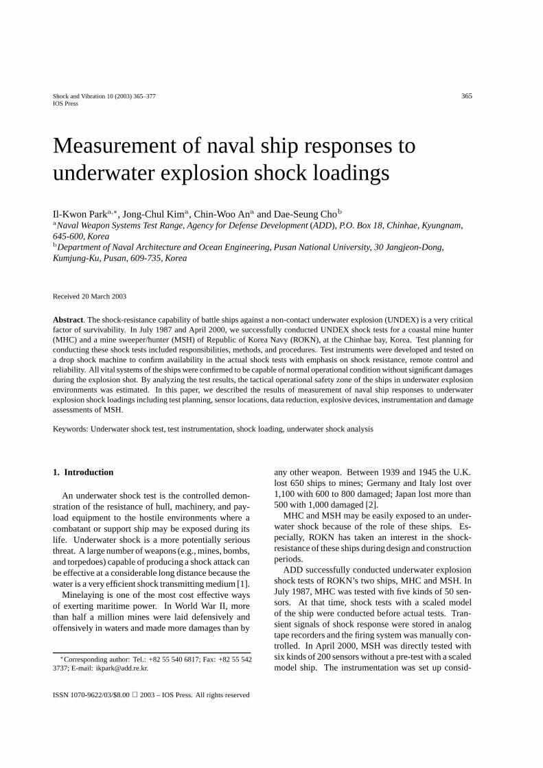
Fig. 1. Schematic diagram of test instrumentation.
Table 1Characteristics of sensors
Type Model Range
Accelerometer PCB305A05 2500 gDisplacement gage GE-4.01 6 inchPressure gage PCB138A10 10,000 psiStrain gage M/M CO. 50,000µεVelocity meter GE-2.75 20 ft/sHigh speed camera KODAK HG2000 1,000 fr/s
2.6. Target ships for the test
Generally, the crew and basic hull possess an inher-ently high degree of shock resistance compared to thepayload equipments aboard the ship. The use of highlysophisticated and complex systems aboard the ship hastended to increase the susceptibility of equipment tohigh shock loadings.
For combatant ship construction programs, a ship ofthe class will be recommended to undergo a shock test.The lead ship of a class is usually designated to undergoa shock test so that shock-hardening modifications canbe incorporated into the following ships during con-struction. For non-combatant ships, a representativeship of each class is selected in the same manner asabove. Service craft and small landing craft normallydon’t need shock tests.
Shock tests are highly recommended to be performedjust prior to the Post-Shakedown Availability (PSA), sothat any damage can be repaired and shock-hardeningmodifications can be installed during PSA.
2.7. Test ranges
No special range facilities are required for shocktests. A requirement is sufficient water depth to re-duce the effect of the reflected shock wave. In gen-eral, water depth of 100 fathoms (180 m) is required inNAVSEA [4].
Tests must be conducted in an area where swimmersand divers can be cleared from the waters to a distanceof 20 miles from the point of test explosions. It isnecessary to avoid conducting trials in shipping lanesor in commercial fishing areas. The waters must bechecked in advance to be satisfactory with respect tosea and weather conditions, environmental factors.
2.8. Sensors
Six kinds of sensors are attached throughout the shipaccording to their purposes. Specially designed, sizeof 60× 60× 10 mm, aluminum accelerometer mountsare positioned and tightly glued with GRP resin on thehull bottoms to adequately obtain transient signals.
The primary purposes of the sensors are as follows;
– pressure gages for recording underwater shock en-vironments,
– strain gages for structural and material responseevaluations,
– displacement gages for relative motions of equip-ment foundations,
368 I.-K. Park et al. / Measurement of naval ship responses to underwater explosion shock loadings
Table 2Characteristics of controller
Type Specification & Capability
Hardware ◦ Rugged PC (Pentium Pro)◦ 64 MB RAM Memory/Super VGA card◦ Equipment control/data communication interface card◦ Recorder, high-speed camera and firing system interface card
Software ◦ Control of recorder, high-speed camera and firing system◦ Countdown, timer and display◦ Checking the synchronous operation of recording system and display◦ Monitoring measurement system◦ Data back-up, play back and analysis
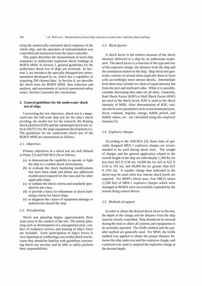
Fig. 2. View of drop shock test.
– accelerometers for structural and equipment shockresponse motions,
– velocity-meter for structural shock response mo-tions at keel position.
– In addition,high-speed motion cameras with lightsfor structural motion behaviors are installed at se-lected positions.
2.9. Underwater shock analysis
Pre-shot analyses for the whole ship are performedto obtain measuring ranges and to assess the integrityof target ship. Comparisons between test and analysis
Table 3Characteristics of recorder system
Type Capability
Recording type Digital recording (SRAM)Storage memory 200CH*2MByte/Ch.A/D converter 12 bit resolutionSampling frequency 200 kHz (variable/channel)Anti-aliasing filter 10 k, 20 k, 80 kHz (variable
in steps)Input range 10V (variable in steps)Model (40ch/set) PSO5570C+PSO9000*2ea
are performed as post-shot evaluation. The details ofsoftware utilized by ADD for shock analyses are asfollows;
– ASRA for the approximate ship shock responseanalysis due to shock wave (ADD code),
– SSRA3D based on the DAA(Doubly AsymptoticApproximation) for the 3D ship shock responseanalysis due to shock wave (ADD code),
– Filtering, FFT and shock response spectrum soft-ware for the analysis of test results [6].
3. Instrumentation
3.1. Test instrumentation
Specially-designed test instrumentation capable ofacquiring 200 channel data, composed of various sen-sors, signal and control cables, signal conditioningunit,digital tape recording unit and controller were installedprior to the tests.
A central control instrumentation for recording andfiring control device was located on the 02-deck ofMSH with an awning stanchion to prevent sea watersplashing on near explosions.
The schematic diagram of test instrumentation isshown in Fig. 1 and principal characteristics of testinstrumentation are summarized in Tables 1–4.
I.-K. Park et al. / Measurement of naval ship responses to underwater explosion shock loadings 369
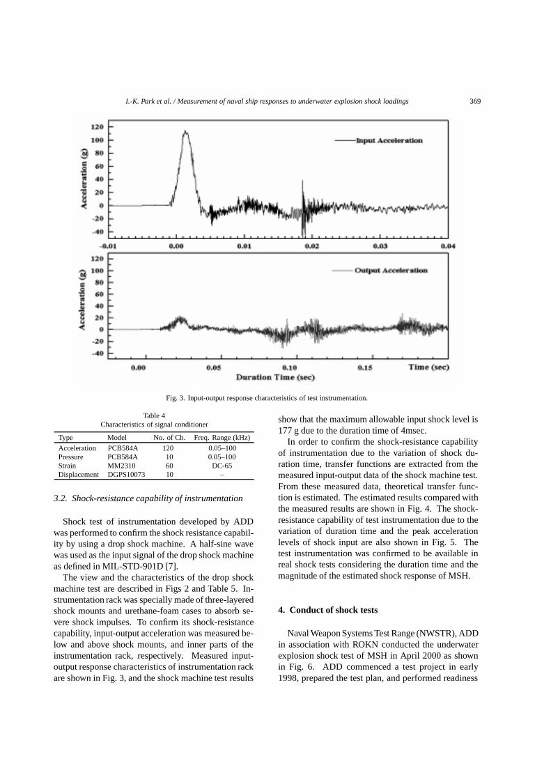
Fig. 3. Input-output response characteristics of test instrumentation.
Table 4Characteristics of signal conditioner
Type Model No. of Ch. Freq. Range (kHz)
Acceleration PCB584A 120 0.05–100Pressure PCB584A 10 0.05–100Strain MM2310 60 DC-65Displacement DGPS10073 10 –
3.2. Shock-resistance capability of instrumentation
Shock test of instrumentation developed by ADDwas performed to confirm the shock resistance capabil-ity by using a drop shock machine. A half-sine wavewas used as the input signal of the drop shock machineas defined in MIL-STD-901D [7].
The view and the characteristics of the drop shockmachine test are described in Figs 2 and Table 5. In-strumentation rack was specially made of three-layeredshock mounts and urethane-foam cases to absorb se-vere shock impulses. To confirm its shock-resistancecapability, input-output acceleration was measured be-low and above shock mounts, and inner parts of theinstrumentation rack, respectively. Measured input-output response characteristics of instrumentation rackare shown in Fig. 3, and the shock machine test results
show that the maximum allowable input shock level is177 g due to the duration time of 4msec.
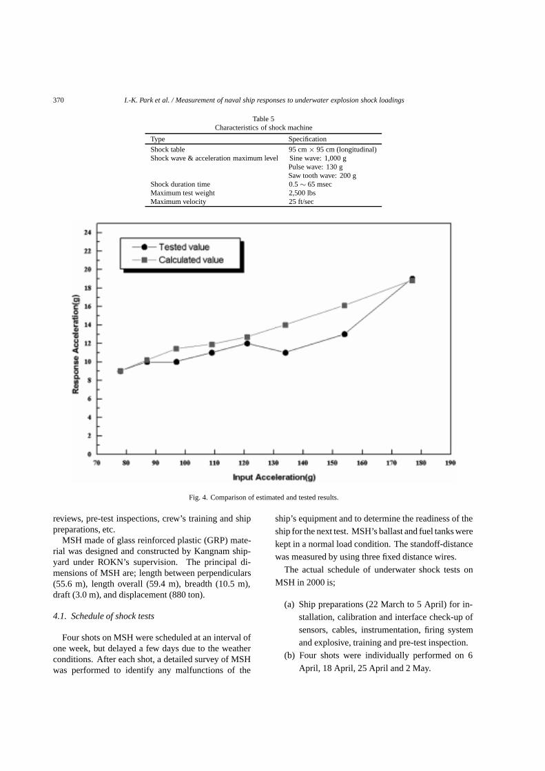
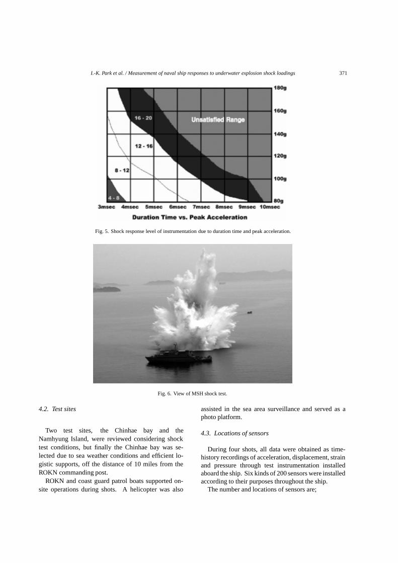
In order to confirm the shock-resistance capabilityof instrumentation due to the variation of shock du-ration time, transfer functions are extracted from themeasured input-output data of the shock machine test.From these measured data, theoretical transfer func-tion is estimated. The estimated results compared withthe measured results are shown in Fig. 4. The shock-resistance capability of test instrumentation due to thevariation of duration time and the peak accelerationlevels of shock input are also shown in Fig. 5. Thetest instrumentation was confirmed to be available inreal shock tests considering the duration time and themagnitude of the estimated shock response of MSH.
4. Conduct of shock tests
Naval Weapon Systems Test Range (NWSTR), ADDin association with ROKN conducted the underwaterexplosion shock test of MSH in April 2000 as shownin Fig. 6. ADD commenced a test project in early1998, prepared the test plan, and performed readiness
370 I.-K. Park et al. / Measurement of naval ship responses to underwater explosion shock loadings
Table 5Characteristics of shock machine
Type Specification
Shock table 95 cm× 95 cm (longitudinal)Shockwave & acceleration maximum level Sinewave: 1,000 g
Pulsewave: 130 gSaw toothwave: 200 g
Shock duration time 0.5∼ 65 msecMaximum test weight 2,500 lbsMaximum velocity 25 ft/sec
Fig. 4. Comparison of estimated and tested results.
reviews, pre-test inspections, crew’s training and shippreparations, etc.
MSH made of glass reinforced plastic (GRP) mate-rial was designed and constructed by Kangnam ship-yard under ROKN’s supervision. The principal di-mensions of MSH are; length between perpendiculars(55.6 m), length overall (59.4 m), breadth (10.5 m),draft (3.0 m), and displacement (880 ton).
4.1. Schedule of shock tests
Four shots on MSH were scheduled at an interval ofone week, but delayed a few days due to the weatherconditions. After each shot, a detailed survey of MSHwas performed to identify any malfunctions of the
ship’s equipment and to determine the readiness of the
ship for the next test. MSH’s ballast and fuel tanks were
kept in a normal load condition. The standoff-distance
was measured by using three fixed distance wires.
The actual schedule of underwater shock tests on
MSH in 2000 is;
(a) Ship preparations (22 March to 5 April) for in-
stallation, calibration and interface check-up of
sensors, cables, instrumentation, firing system
and explosive, training and pre-test inspection.
(b) Four shots were individually performed on 6
April, 18 April, 25 April and 2 May.
I.-K. Park et al. / Measurement of naval ship responses to underwater explosion shock loadings 371
Fig. 5. Shock response level of instrumentation due to duration time and peak acceleration.
Fig. 6. View of MSH shock test.
4.2. Test sites
Two test sites, the Chinhae bay and theNamhyung Island, were reviewed considering shocktest conditions, but finally the Chinhae bay was se-lected due to sea weather conditions and efficient lo-gistic supports, off the distance of 10 miles from theROKN commanding post.
ROKN and coast guard patrol boats supported on-site operations during shots. A helicopter was also
assisted in the sea area surveillance and served as aphoto platform.
4.3. Locations of sensors
During four shots, all data were obtained as time-history recordings of acceleration, displacement, strainand pressure through test instrumentation installedaboard the ship. Six kinds of 200 sensors were installedaccording to their purposes throughout the ship.
The number and locations of sensors are;
372 I.-K. Park et al. / Measurement of naval ship responses to underwater explosion shock loadings
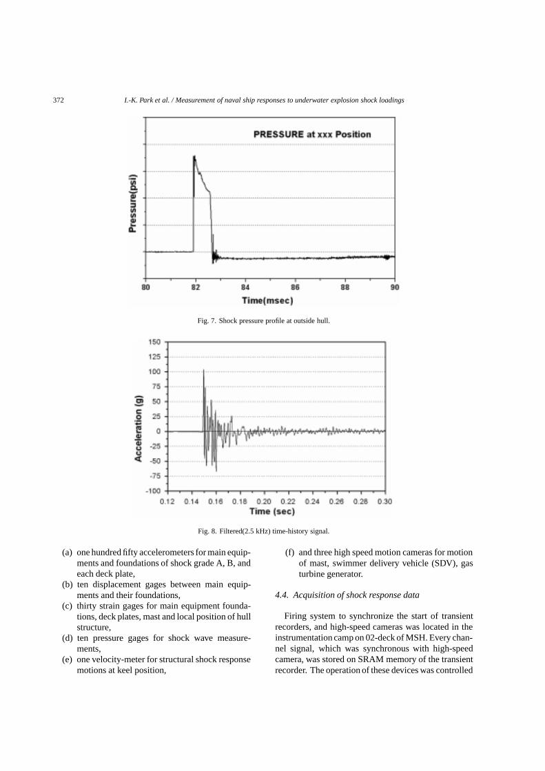
Fig. 7. Shock pressure profile at outside hull.
Fig. 8. Filtered(2.5 kHz) time-history signal.
(a) one hundred fifty accelerometers for main equip-ments and foundations of shock grade A, B, andeach deck plate,
(b) ten displacement gages between main equip-ments and their foundations,
(c) thirty strain gages for main equipment founda-tions, deck plates, mast and local position of hullstructure,
(d) ten pressure gages for shock wave measure-ments,
(e) one velocity-meter for structural shock responsemotions at keel position,
(f) and three high speed motion cameras for motionof mast, swimmer delivery vehicle (SDV), gasturbine generator.
4.4. Acquisition of shock response data
Firing system to synchronize the start of transientrecorders, and high-speed cameras was located in theinstrumentation camp on 02-deck of MSH. Every chan-nel signal, which was synchronous with high-speedcamera, was stored on SRAM memory of the transientrecorder. The operation of these devices was controlled

I.-K. Park et al. / Measurement of naval ship responses to underwater explosion shock loadings 373
Fig. 9. Shock Response Spectrum at the foundation of main equipment.
Fig. 10. Estimation of maximum acceptable acceleration.
and monitored from the main controller in the instru-mentation camp. In the bridge, the operation statusand the countdown clock on a computer monitor weredisplayed.
For reliable data acquisition, the input-ranges of sig-nals in transient recorders should be adjusted to propervalues. The instrumentation was set up considering thenumerically estimated peak values of the whole shipanalysis. Accordingly, reliable data were measured onevery shots.
4.5. Data reduction and analysis
Shock factors of the real tests are reviewed by us-ing the shock pressure wave profile of the underwaterexplosion as shown in Fig. 7. For data reduction ofacceleration, strain, velocity, and displacement signals,primary time-history signals are filtered by 2.5 kHzlow-pass filter as shown in Fig. 8. From the analysisfor shock response spectra of the main equipments andthe hull structure, the peak responses during the pulseare estimated as shown in Fig. 9. The principal normal
374 I.-K. Park et al. / Measurement of naval ship responses to underwater explosion shock loadings
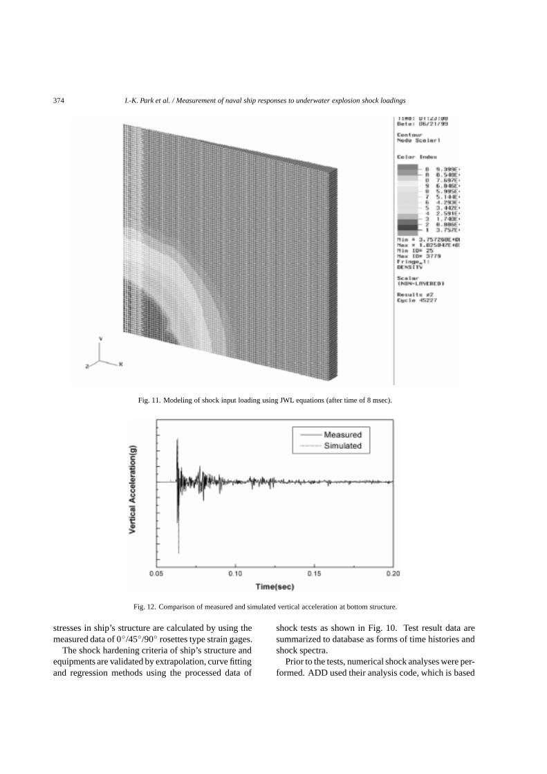
Fig. 11. Modeling of shock input loading using JWL equations (after time of 8 msec).
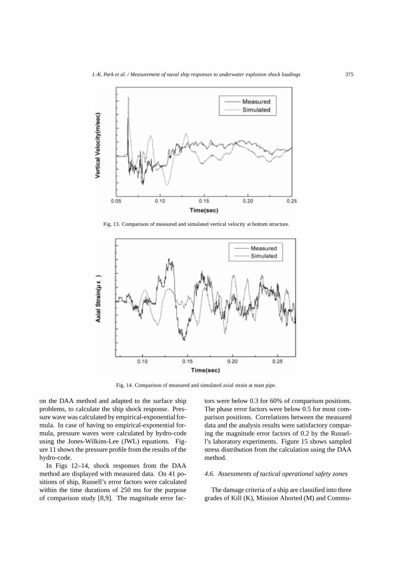
Fig. 12. Comparison of measured and simulated vertical acceleration at bottom structure.
stresses in ship’s structure are calculated by using themeasured data of 0◦/45◦/90◦ rosettes type strain gages.
The shock hardening criteria of ship’s structure andequipments are validated by extrapolation, curve fittingand regression methods using the processed data of
shock tests as shown in Fig. 10. Test result data aresummarized to database as forms of time histories andshock spectra.
Prior to the tests, numerical shock analyses were per-formed. ADD used their analysis code, which is based
I.-K. Park et al. / Measurement of naval ship responses to underwater explosion shock loadings 375
Fig. 13. Comparison of measured and simulated vertical velocity at bottom structure.
Fig. 14. Comparison of measured and simulated axial strain at mast pipe.
on the DAA method and adapted to the surface shipproblems, to calculate the ship shock response. Pres-sure wave was calculated by empirical-exponential for-mula. In case of having no empirical-exponential for-mula, pressure waves were calculated by hydro-codeusing the Jones-Wilkins-Lee (JWL) equations. Fig-ure 11 shows the pressure profile from the results of thehydro-code.
In Figs 12–14, shock responses from the DAAmethod are displayed with measured data. On 41 po-sitions of ship, Russell’s error factors were calculatedwithin the time durations of 250 ms for the purposeof comparison study [8,9]. The magnitude error fac-
tors were below 0.3 for 60% of comparison positions.The phase error factors were below 0.5 for most com-parison positions. Correlations between the measureddata and the analysis results were satisfactory compar-ing the magnitude error factors of 0.2 by the Russel-l’s laboratory experiments. Figure 15 shows sampledstress distribution from the calculation using the DAAmethod.
4.6. Assessments of tactical operational safety zones
The damage criteria of a ship are classified into threegrades of Kill (K), Mission Aborted (M) and Commu-
376 I.-K. Park et al. / Measurement of naval ship responses to underwater explosion shock loadings
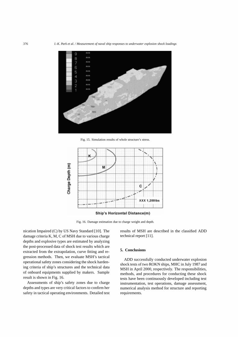
Fig. 15. Simulation results of whole structure’s stress.
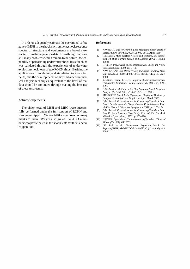
Fig. 16. Damage estimation due to charge weight and depth.
nication Impaired (C) by US Navy Standard [10]. Thedamage criteria K, M, C of MSH due to various chargedepths and explosive types are estimated by analyzingthe post-processed data of shock test results which areextracted from the extrapolation, curve fitting and re-gression methods. Then, we evaluate MSH’s tacticaloperational safety zones considering the shock harden-ing criteria of ship’s structures and the technical dataof onboard equipments supplied by makers. Sampleresult is shown in Fig. 16.
Assessments of ship’s safety zones due to chargedepths and types are very critical factors to confirm hersafety in tactical operating environments. Detailed test
results of MSH are described in the classified ADDtechnical report [11].
5. Conclusions
ADD successfully conducted underwater explosionshock tests of two ROKN ships, MHC in July 1987 andMSH in April 2000, respectively. The responsibilities,methods, and procedures for conducting these shocktests have been continuously developed including testinstrumentation, test operations, damage assessment,numerical analysis method for structure and reportingrequirements.
I.-K. Park et al. / Measurement of naval ship responses to underwater explosion shock loadings 377
In order to adequately estimate the operational safetyzone of MSH in the shock environment, shock responsespectra of structure and equipments are broadly ex-tracted from the acquisition data. Even though there arestill many problems which remain to be solved, the ca-pability of performing underwater shock tests for shipswas validated through the experiences of underwaterexplosion shock tests of two ROKN ships. Besides, theapplications of modeling and simulation to shock testfields, and the developments of more advanced numer-ical analysis techniques equivalent to the level of realdata should be continued through making the best useof these test results.
Acknowledgements
The shock tests of MSH and MHC were success-fully performed under the full support of ROKN andKangnam shipyard. We would like to express our manythanks to them. We are also grateful to ADD mem-bers who participated in the shock tests for their sincerecooperation.
References
[1] NAVSEA, Guide for Planning and Managing Shock Trials ofSurface Ships, NAVSEA 0908-LP-000-0010, April 1989.
[2] R.J. Daniel, Mine Warfare Vessels and Systems,Int. Sympo-sium on Mine Warfare Vessels and Systems, RINA I(1) (Jun.1984).
[3] H. Pusey,Underwater Shock Measurement, Shock and Vibra-tion Digest, Dec. 1989, pp. 9–11.
[4] NAVSEA, Ship Post-Delivery Tests and Trials Guidance Man-ual, NAVSEA 0900-LP-095-3010, Rev.1, Chap.13, Aug,1989.
[5] Y.S. Shin, Thomas L. Geers,Response of Marine Structures toUnderwater Explosion, Lecture Notes, Feb. 1993, pp. 3.24–3.25.
[6] C.W. An et al.,A Study on the Ship Structure Shock ResponseAnalysis (I), ADD NSDC-513-991203, Dec. 1999.
[7] MIL-S-901D,Shock Tests, High Impact Shipboard Machinery,Equipment, and Systems, Requirement for, March 1989.
[8] D.M. Russell,Error Measures for Comparing Transient Data:Part I: Development of a Comprehensive Error Measure, Proc.of 68th Shock & Vibration Symposium, 1997, pp. 175–184.
[9] D.M. Russell,Error Measures for Comparing Transient Data:Part II: Error Measure Case Study, Proc. of 68th Shock &Vibration Symposium, 1997, pp. 185–198.
[10] NAVSEA, Operational Characteristics of Standard US NavalMines, (Vol. I,II), OP2637.
[11] I.K. Park et al., Underwater Explosion Shock TestReport of MSH, ADD NSDC-313- 000928C (Classified), Oct.2000.

International Journal of
AerospaceEngineeringHindawi Publishing Corporationhttp://www.hindawi.com Volume 2010
RoboticsJournal of
Hindawi Publishing Corporationhttp://www.hindawi.com Volume 2014
Hindawi Publishing Corporationhttp://www.hindawi.com Volume 2014
Active and Passive Electronic Components
Control Scienceand Engineering
Journal of
Hindawi Publishing Corporationhttp://www.hindawi.com Volume 2014
International Journal of
RotatingMachinery
Hindawi Publishing Corporationhttp://www.hindawi.com Volume 2014
Hindawi Publishing Corporation http://www.hindawi.com
Journal ofEngineeringVolume 2014
Submit your manuscripts athttp://www.hindawi.com
VLSI Design
Hindawi Publishing Corporationhttp://www.hindawi.com Volume 2014
Hindawi Publishing Corporationhttp://www.hindawi.com Volume 2014
Shock and Vibration
Hindawi Publishing Corporationhttp://www.hindawi.com Volume 2014
Civil EngineeringAdvances in
Acoustics and VibrationAdvances in
Hindawi Publishing Corporationhttp://www.hindawi.com Volume 2014
Hindawi Publishing Corporationhttp://www.hindawi.com Volume 2014
Electrical and Computer Engineering
Journal of
Advances inOptoElectronics
Hindawi Publishing Corporation http://www.hindawi.com
Volume 2014
The Scientific World JournalHindawi Publishing Corporation http://www.hindawi.com Volume 2014
SensorsJournal of
Hindawi Publishing Corporationhttp://www.hindawi.com Volume 2014
Modelling & Simulation in EngineeringHindawi Publishing Corporation http://www.hindawi.com Volume 2014
Hindawi Publishing Corporationhttp://www.hindawi.com Volume 2014
Chemical EngineeringInternational Journal of Antennas and
Propagation
International Journal of
Hindawi Publishing Corporationhttp://www.hindawi.com Volume 2014
Hindawi Publishing Corporationhttp://www.hindawi.com Volume 2014
Navigation and Observation
International Journal of
Hindawi Publishing Corporationhttp://www.hindawi.com Volume 2014
DistributedSensor Networks
International Journal of