measurement of em clamp coupling characteristics 14 observations for cat 6a utp measurements • cat...
TRANSCRIPT

Larry Cohen
Measurement ofEM ClampCouplingCharacteristics
July 1, 2015
7/1/2015 2
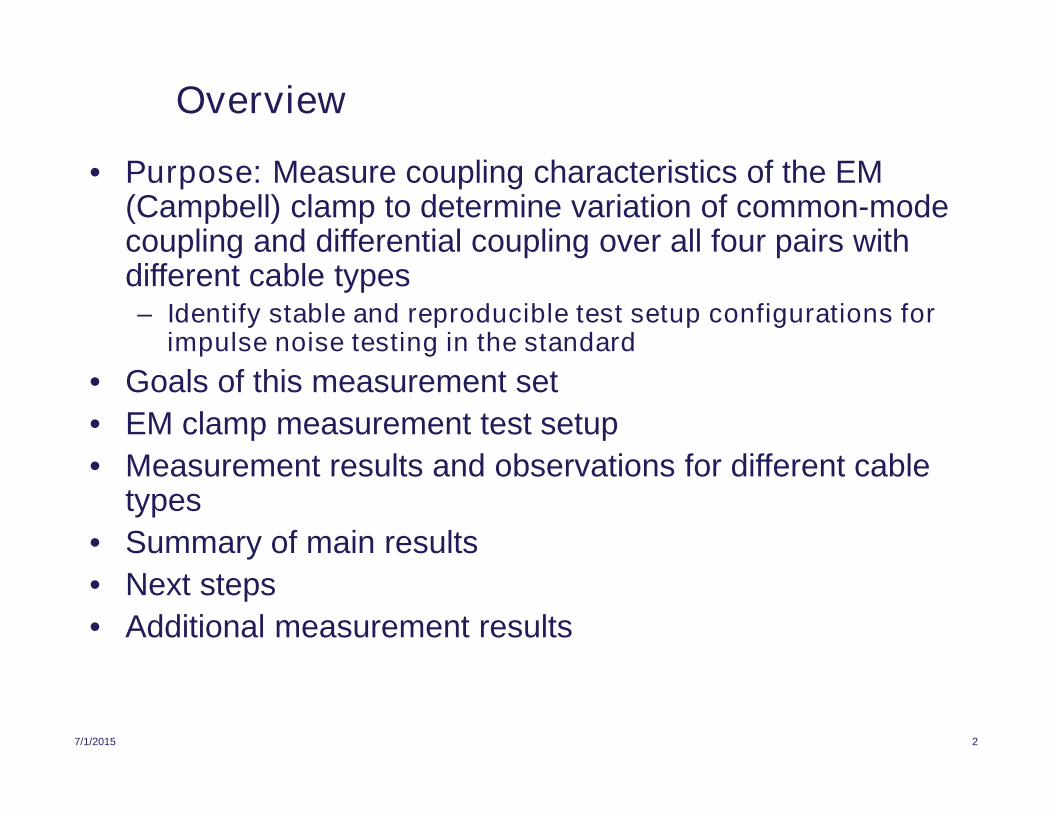
Overview
• Purpose: Measure coupling characteristics of the EM(Campbell) clamp to determine variation of common-modecoupling and differential coupling over all four pairs withdifferent cable types– Identify stable and reproducible test setup configurations for
impulse noise testing in the standard
• Goals of this measurement set
• EM clamp measurement test setup
• Measurement results and observations for different cabletypes
• Summary of main results
• Next steps
• Additional measurement results

7/1/2015 3
Goals of this Measurement Set
• Determine usage limitations of the EM clamp for impulse noise andradiated immunity pre-compliance testing– Impulse noise test bandwidth depends upon data rate (below 400 MHz for 1G,
2.5G and 5G), radiated immunity testing requires useful bandwidth up to 1 GHz
• Determine variation of injected common-mode and differential signalsacross all four pairs– Common-mode coupling variation should be minimal across all four pairs
– Differential coupling variations across all four pairs should not be too extreme
– Ratio of differential to common-mode coupling should not change much withdifferent test setup configurations
– Above criteria will determine the useful frequency range of the EM couplingclamp
• Is the ratio of common-mode to differential coupling consistent withexternal field coupling results ?– Evaluation will require examination of EMC lab test data
• Main goal: Identify stable and reproducible test setup configurations forimpulse noise testing in the standard

7/1/2015 4
EM Clamp Measurement Test Setup
100 Ohm DM+ 50 Ohm CMTermination
EM Coupling Clamp(ETS CC-101)
L3
RJ45-to-SMABreakout andTermination
Box 61
Logical differential port allows network analyzer tocompute both differential-mode and common-modecoupling in a single (per pair) measurement.
50 50
L3 >= 2 meters
Agilent E5071A 4-Port Network Analyzer
Logical Port #3(Differential 100 )
Port 1 Port 2 Port 3 Port 4
50
Metal groundplate
Network analyzer measures common-mode anddifferential-mode coupling from the coupling clampinto one of four pairs.
50
All unused pairs on the RJ45 Breakout andTermination Box are terminated with 50 Ohms.
The RJ45 connector and enclosure are fullyshielded, and the enclosure is bonded to themetal ground plate.
Cat 5e/6/6A UTP patch cordused in test channel (>2m)Cable above ground plane forms a
common-mode transmission line. Z0
determined by height above plane.
RJ45
Logical Port #2(Single-ended 50 )
Logical Port #1(Single-ended 50 )
RJ4531 75
Ferrite clamps(baseline)
L2 = 2 cm
L2
L1
L1 = 15 cm
75 / 31
Optional EUT port(low-frequency)
ferrite clamp

7/1/2015 5
Summary of Measurement Results
• Test cables
– 7ft Cat 6A UTP patch cord
– 7ft Cat 5e UTP patch cord (stabilized in clamp with tape)
• Measured parameters (frequency response plots for each parameter)
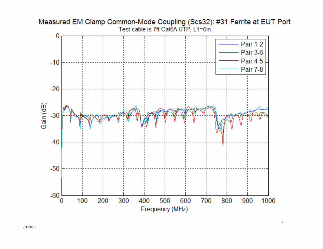
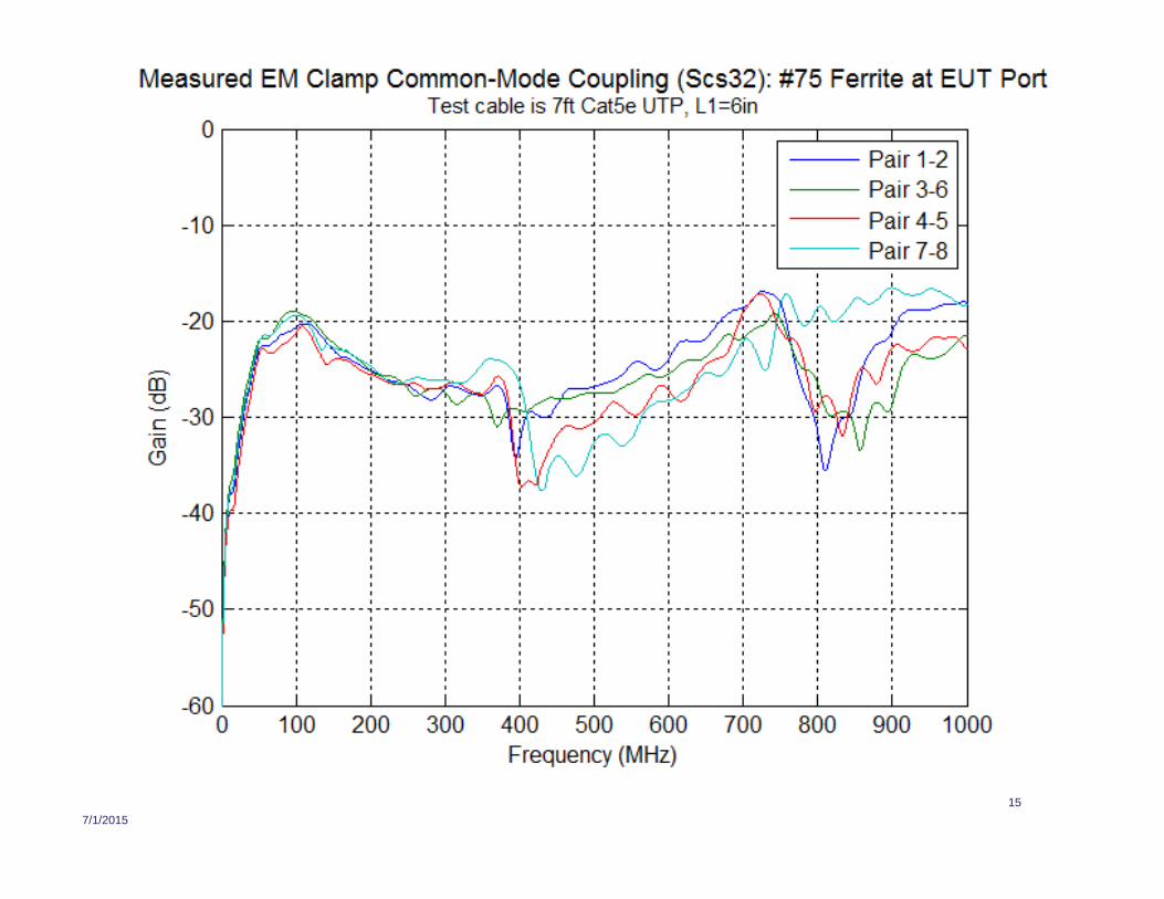
– Measured common-mode coupling all four cable pairs (Scs32)
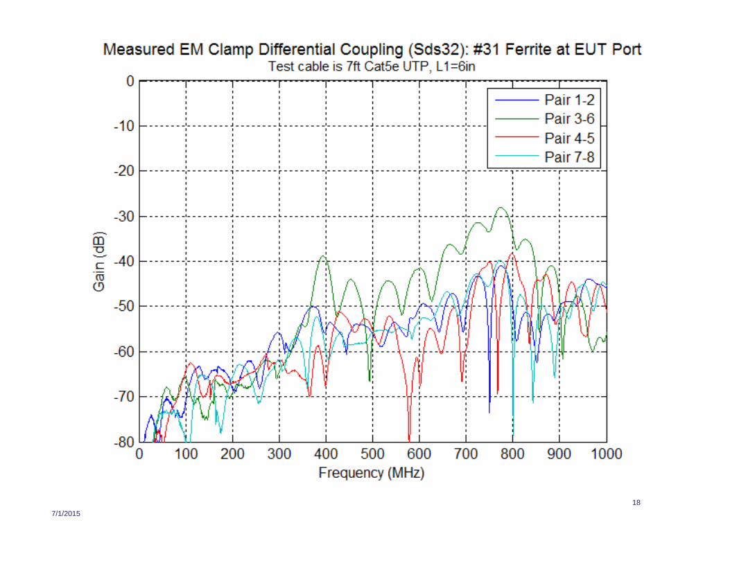
– Measured differential coupling into all four cable pairs (Sds32)
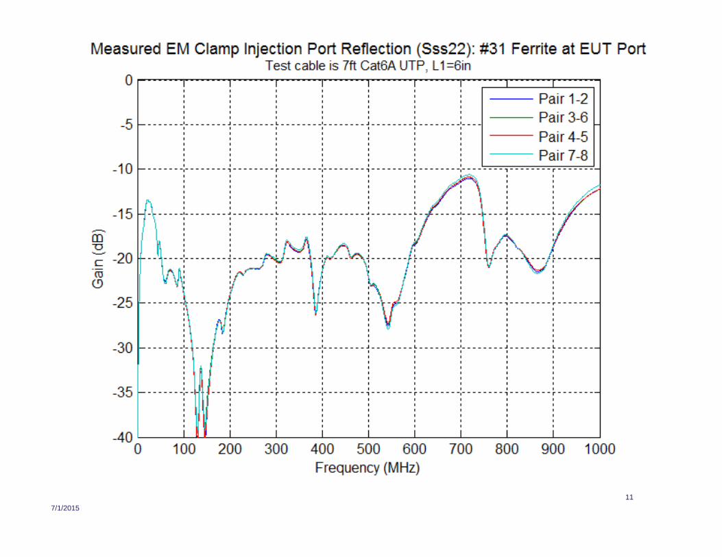
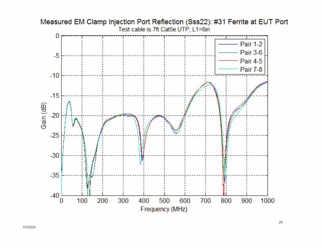
– Measured clamp injection port reflection over all four cable pairs (Sss22)
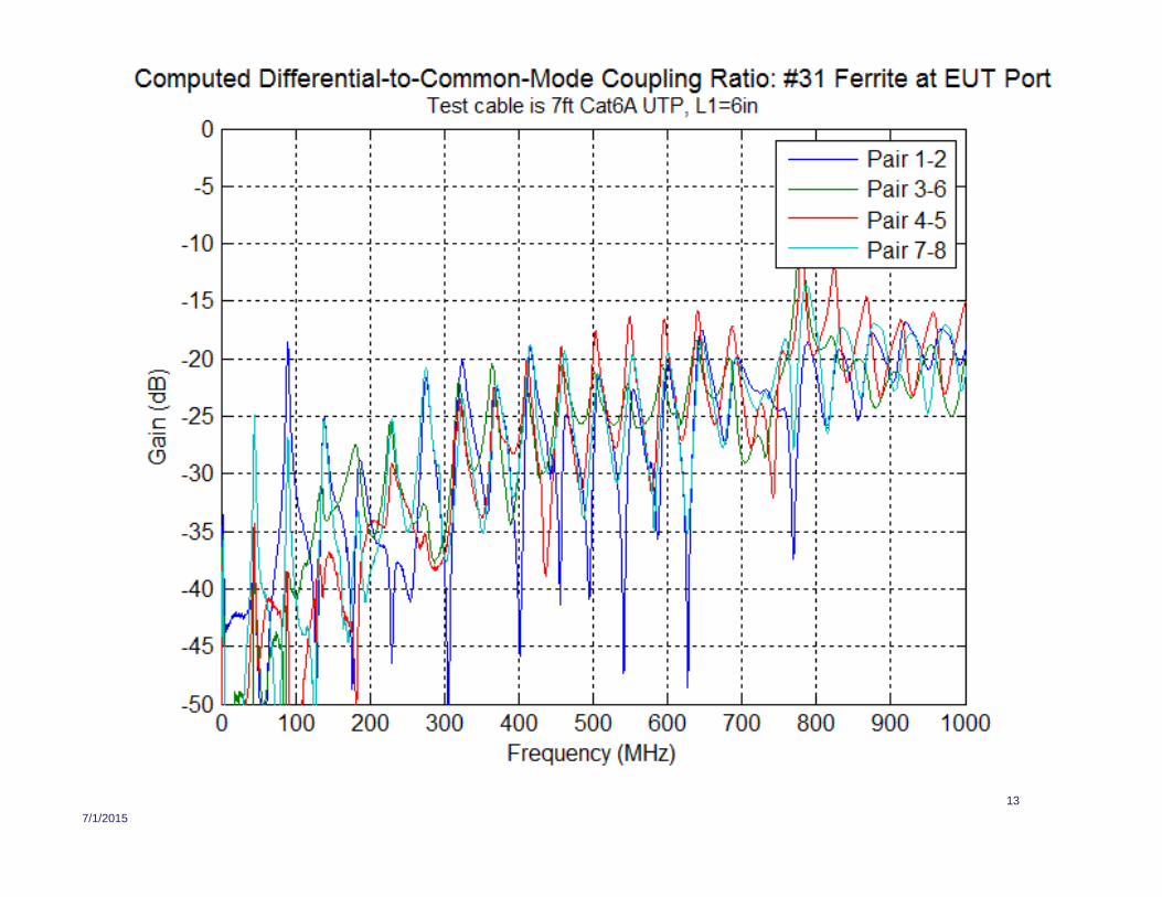
– Computed differential to common-mode coupling ratio
• Test setup configurations
– Added #75 ferrite clamp at EUT port of clamp
– Added #31 ferrite clamp at EUT port of clamp
• A full measurement data set for Cat 6 UTP was not completed, but thepartial results were similar to Cat 5e UTP

7/1/2015
6
7/1/2015
7

7/1/2015
8

7/1/2015
9

7/1/2015
10
7/1/2015
11

7/1/2015
12
7/1/2015
13

7/1/2015 14
Observations for Cat 6A UTP Measurements
• Cat 6A UTP provides consistent common-mode coupling across all fourpairs to at least 800 MHz
– Cat 6A UTP common-mode coupling has nulls from far-end reflection of the testcable
– Depth of far-end reflection nulls reduced with when a #31 ferrite clamp isplaced at the EUT port of the clamp; also flattens frequency response
– Common-mode coupling null near 400 MHz is not as excessively deep
– Cat 6A UTP setup stable over L1 distance variation (see AdditionalMeasurement Data)
• Injection port reflection improves with the addition of EUT ferrite clamps,especially with the #31 ferrite clamp
• Because of the larger cable diameter, Cat 6A UTP is “frozen” inside clamp(barely fits inside the CC-101 clamp) which actually improvesreproducibility
• Differential to common-mode coupling ratio remains does not changemuch with different test setup configurations
7/1/2015
15

7/1/2015
16

7/1/2015
17
7/1/2015
18

7/1/2015
19
7/1/2015
20

7/1/2015
21

7/1/2015
22

7/1/2015 23
Observations for Cat 5e UTP Measurements
• Cat 5e UTP provides consistent common-mode couplingacross all four pairs to at least 350 MHz– Cat 5e UTP common-mode coupling does not have nulls from far-end
reflection of the test cable– Difficult to eliminate deep null near 400 MHz without “tuning” the setup
using a network analyzer (“tuning” is adjusting cable position, baselineferrite position, and L1 distance)
– Restrictions on L1 distance not sufficient to eliminate deep nulls• Injection port reflection improves with the addition of EUT ferrite clamps,
especially with the #31 ferrite clamp• Cat 5e UTP and Cat 6 UTP can slide inside of clamp and cause possible
reproducibility issues– Problem may be mitigated by wrapping tape around cable to increase its
diameter inside the clamp and freeze its position (don’t use a tape with a highdielectric constant
• Differential to common-mode coupling ratio remains does not changemuch with different test setup configurations

7/1/2015 24
Main Observations and Results
• There is a significant variation in the EM coupling characteristics betweenCat 5e / Cat 6 UTP and Cat 6A UTP
• The useful frequency limit of the EM coupling clamp is limited to about 350MHz for Cat 5e/ Cat 6 UTP, but may extend to 1 GHz for Cat 6A UTP.– CM coupling variation increases above coupling null near 400 MHz– Can’t eliminate deep CM coupling null near 400 MHz without “tuning” the test
setup; problem is slightly worse for Cat 6 UTP than Cat 5e UTP– The EM clamp is useful for impulse noise testing for 1G/2.5G/5G data rates with
Cat 5e UTP and Cat 6 UTP, but not for the 10G data rate unless Cat 6A UTP isused
– Use of the EM clamp for pre-compliance radiated immunity testing to 1 GHzwith Cat 5e / Cat 6 UTP is limited; may need a significant power amplifier toovercome coupling nulls near 400 MHz and 800 MHz
• Use of Cat 6A UTP in the EM clamp provides more stable injectioncharacteristics, but it is unknown if the differential-to-common-modecoupling ratio is similar to to results observed in an EMC test lab
• Adding a #75 ferrite clamp at the EUT port is may be best for radiatedimmunity test applications; adding a #31 ferrite at the EUT port may bebest for (wideband) impulse injection applications
7/1/2015 25
Next Steps
• Need to verify Cat 6A UTP coupling stability over variousCat 6A cable samples (in progress)
• Measure impedance of ferrite clamp network(s) to provide aproper standard specification (in progress)
• Determine if the ratio of common-mode to differentialcoupling for the shown cable configuration is consistent withexternal field coupling results– Evaluation will require examination of EMC lab test data
• Test clamp coupling with screened and shielded cable
• Define an impulse waveform generation method for impulsenoise testing with the EM clamp (in progress)

7/1/2015 26
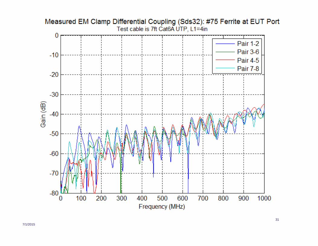
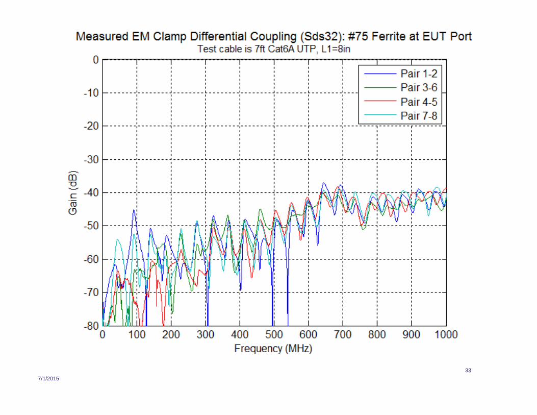
Additional Measurement Data
• Determine stability of Cat 6A UTP setup over variation of L1distance
• Test cable is 7ft Cat 6A UTP patch cord
• Measured parameters (frequency response plots for eachparameter)– Measured common-mode coupling all four cable pairs (Scs32)
– Measured differential coupling into all four cable pairs (Sds32)
• Test setup configurations– Added #75 ferrite clamp at EUT port of clamp, L1 = 4 inches
– Added #31 ferrite clamp at EUT port of clamp, L1 = 4 inches
– Added #75 ferrite clamp at EUT port of clamp, L1 = 8 inches
– Added #31 ferrite clamp at EUT port of clamp, L1 = 8 inches

7/1/2015
27

7/1/2015
28

7/1/2015
29

7/1/2015
30
7/1/2015
31

7/1/2015
32
7/1/2015
33

7/1/2015
34