measurement and inspection and testing · international system (si), the english system of feet and...
TRANSCRIPT

Veljko SamardzicME-215 Engineering Materials and Processes
Measurement and Inspection and
Testing
Chapter 35
Chapter 43

Veljko SamardzicME-215 Engineering Materials and Processes
35.1 Introduction
• Measurement
– Act of measuring or being measured
– Fundamental activity of testing and inspection
• Inspection
– Ensures what is being manufactured will meet
specifications
• Testing
– Evaluates product quality or performance

Veljko SamardzicME-215 Engineering Materials and Processes
Manufacturing Principles
• Products are manufactured to standard sizes
and shapes
• Interchangeable parts became common in
the early 1900’s
• Design engineer may have to design or alter
specifications to ease manufacturing,
assembly, and inspection or lower costs
– These changes should not sacrifice
functionality, product reliability, or
performance

Veljko SamardzicME-215 Engineering Materials and Processes
Attributes vs. Variables
• Inspection of a product can be done in two
main ways
– Attributes (Gaging)
• Uses gages
• Reported as YES/NO, GO/NO GO
– Variables (Measurements)
• Uses calibrated instruments
• Reported in actual dimensions

Veljko SamardzicME-215 Engineering Materials and Processes
35.2 Standards of Measurement
• Fundamental measures
– Length, time, mass, temperature
– Candela, ampere
• All other measurements can be made using a combination of the fundamental measures
• Linear standards
– International meter is the standard
• Inch is based off of the meter standard as .0254m– 41,929.399 wavelengths of orange-red light from krypton-86
– The US is officially committed to convert to the International System (SI), the English system of feet and inches is still used by many manufacturing plants

Veljko SamardzicME-215 Engineering Materials and Processes

Veljko SamardzicME-215 Engineering Materials and Processes
Metric to English Conversions
• Table 10-2 lists common metric to English
conversions
• Care should be taken when converting
measurements to ensure that standard
conversions have been used
• Standard sizes in the English system may
not have a perfectly matching
corresponding size in the metric system

Veljko SamardzicME-215 Engineering Materials and Processes
Length Standards in Industry
• Gage blocks
– Provide industry with linear
standards of high accuracy
– Small, rectangular, square,
or round in cross section
– Made with steel or carbide
– Two flat and parallel
surfaces
– Calibrated with light-beam
interferometry
– By combining blocks, any
desired dimension can be
obtained
Figure 10-5 Wrung-together gage blocks in
a special holder, used with a dial gage to
form an accurate comparator. (Courtesy of
DoALL Company.)

Veljko SamardzicME-215 Engineering Materials and Processes
Gage Blocks
Figure 10-3 Standard set of rectangular gage blocks with 0.000050-in. accuracy; three
individual blocks are shown.

Veljko SamardzicME-215 Engineering Materials and Processes
Standard Measuring Temperature
• Many metal instruments are used for measuring
• Metals are affected dimensionally by temperature
• Standard measuring temperature of 68°F
(20°C) for precision measuring
• Gage blocks, gages, and other precision-measuring instruments are calibrated at this temperature

Veljko SamardzicME-215 Engineering Materials and Processes
Accuracy Versus Precision in
Processes• Accuracy- ability to
hit what is aimed at
• Precision-repeatability of the process
• Measuring devices must be both precise and accurate
• Skill of the operator may also have to be taken into account for measurements
Figure 10-6 Accuracy versus precision. Dots in targets
represent location of shots. Cross (X) represents the
location of the average positions of all shots.

Veljko SamardzicME-215 Engineering Materials and Processes
35.3 Allowance and Tolerance
• Allowance- intentional, desired difference between two mating parts
– Determines the condition of tightest fit
– May be specified for clearance or interference
• Tolerance- undesirable but permissible deviation from a desired dimensions
– No part can be made exactly to a specified dimension
– Necessary to permit the actual dimension to deviate from the theoretical (nominal) dimension

Veljko SamardzicME-215 Engineering Materials and Processes
Allowance and Tolerance
Figure 10-7 When mating parts are designed, each shaft must be smaller
than each hole for a clearance fit.
Veljko SamardzicME-215 Engineering Materials and Processes
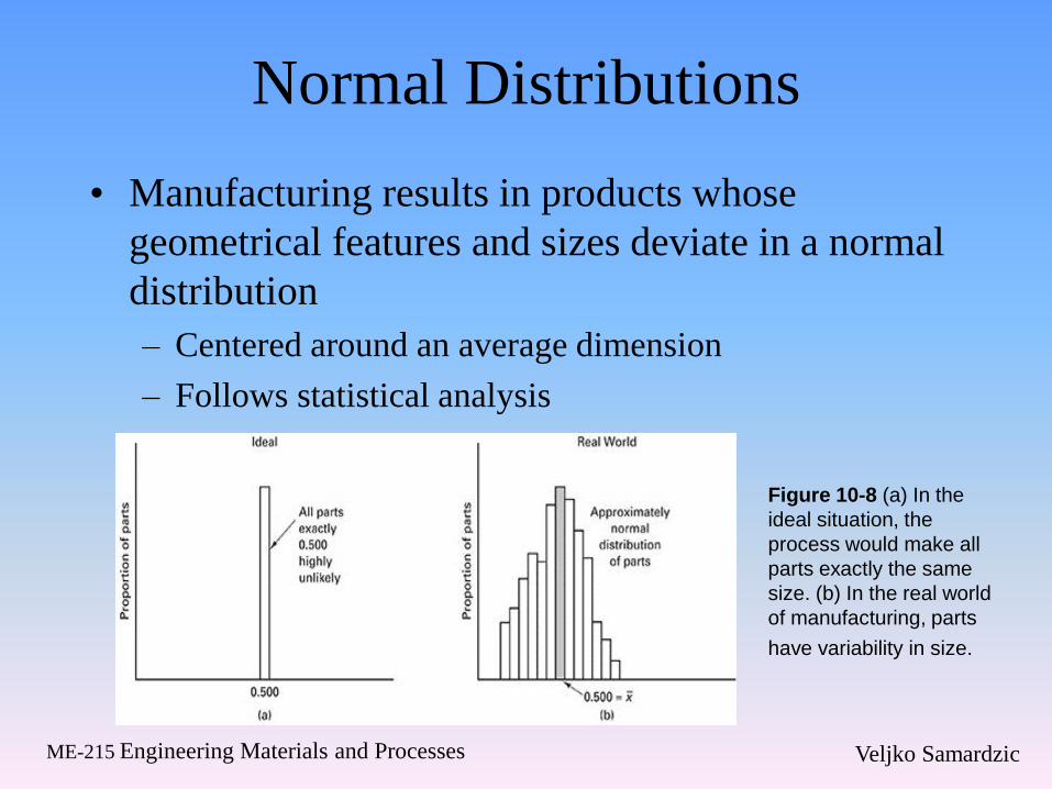
Normal Distributions
• Manufacturing results in products whose
geometrical features and sizes deviate in a normal
distribution
– Centered around an average dimension
– Follows statistical analysis
Figure 10-8 (a) In the
ideal situation, the
process would make all
parts exactly the same
size. (b) In the real world
of manufacturing, parts
have variability in size.

Veljko SamardzicME-215 Engineering Materials and Processes
Normal Distribution
Figure 10-8 (c) The distribution of sizes can often be modeled with a normal distribution.

Veljko SamardzicME-215 Engineering Materials and Processes
Specifying Tolerance and
Allowances• Tolerance can be specified in four ways
– Bilateral, unilateral, limits and geometric
• Bilateral
– Plus or minus deviation from the nominal size
• Unilateral
– Deviation is in one direction from the nominal
size
• Limits
– Maximum and minimum dimensions

Veljko SamardzicME-215 Engineering Materials and Processes
ANSI Classes of Fits
• Class 1: Loose fit
• Class 2: Free fit
• Class 3: Medium fit
• Class 4: Snug fit
• Class 5: Wringing fit
• Class 6: Tight fit
• Class 7: Medium force
• Class 8: Heavy force and shrink fits

Veljko SamardzicME-215 Engineering Materials and Processes
ISO System of Limits and Fits
• Used in metric countries
• Each part has a basic size and each limit is defined
by its limit from that size
– Difference is called the tolerance
• Three classes of fits
– Clearance
– Transition
– Interference
• Tolerances may be specified with respect to zero
deviation

Veljko SamardzicME-215 Engineering Materials and Processes
Geometric Tolerances
• Maximum allowable deviation of a form or
position from the perfect geometry
• Maximum material condition indicates that a part
is made with the maximum allowable material
• Least material condition indicates that a part is
made with the minimum allowable material
• Geometric tolerances are specified with respect to
a datum or reference surface
• Four tolerances
– Flatness, straightness, roundness, and cylindricity

Veljko SamardzicME-215 Engineering Materials and Processes
Geometric Tolerances
Figure 10-11 (a) Geometric tolerancing
symbols; (b) feature control symbols for part
drawings; (c) how a geometric tolerance for
flatness is specified; (d) what the specification
means.

Veljko SamardzicME-215 Engineering Materials and Processes
35.4 Inspection Methods for
Measurement
• Factors in selecting
inspection equipment
– Gage capability
– Linearity
– Repeat accuracy
– Stability
– Magnification
– Resolution
Figure 10-12 The rule of 10 states that for reliable
measurements each successive step in the
inspection sequence should have 10 times the
precision of the preceding step.

Veljko SamardzicME-215 Engineering Materials and Processes
35.5 Measuring Instruments
• Manually operated instruments
– Ease of use, precision, accuracy are affected by:
• Least count of subdivisions
• Line matching
• Parallax
– Linear measuring instruments
• Direct
– Line graduated so that the measurement can be read right off of the scale
• Indirect
– Transfers the size of the dimension to a direct reading scale

Veljko SamardzicME-215 Engineering Materials and Processes
Linear Measuring Devices
Figure 10-13 (above) Machinist’s rules: (a)
metric and (b) inch graduations; 10ths and
100ths on one side; 32nds and 64ths on the
opposite side. (Courtesy of L.S. Starrett
Company.)
Figure 10-14 (below) Combination set.
(Courtesy of MTI Corporation.)

Veljko SamardzicME-215 Engineering Materials and Processes
Vernier Calipers
Figure 10-15 (above) The Vernier caliper can make
measurements using both inside (for holes) and outside
(shafts) anvils.
Figure 10-17 (right) Variations in the Vernier caliper
design result in other basic gages.

Veljko SamardzicME-215 Engineering Materials and Processes
Other Forms of Calipers
Figure 10-18 Three styles of calipers in common
use today: (a) Vernier caliper with inch or metric
scales and 0.001-in. accuracy; (b) dial caliper
with 0.001-in accuracy; (c) digital electronic
caliper with 0.001-in. (0.03-mm) accuracy and
0.0001-in resolution with inch/metric conversion.

Veljko SamardzicME-215 Engineering Materials and Processes
Graduated and Digital
Micrometers
Figure 10-20 Digital micrometer for
measurements from 0 to 1 in., in 0.0001-in.
graduations.
Figure 10-19 Micrometer caliper graduated in
ten-thousandths of an inch with insets A, B, and
C showing two example readings. (Courtesy
Starrett Bulletin No. 1203.)

Veljko SamardzicME-215 Engineering Materials and Processes
Optical Instrumentation
Figure 10-22 Toolmaker’s microscope with digital
readouts for X and Y table movements.
Figure 10-23 Optical comparator,
measuring the contour on a workpiece.
Digital indicators with conversions add to
the utility of optical comparators.

Veljko SamardzicME-215 Engineering Materials and Processes
Measuring with Lasers
• Interferometry
• Uses light interference
bands to determine
distance and thickness of
objects
• Constructive interference-
beams returning are in
phase
• Destructive interference-
beams returning are out of
phase
Figure 10-24 Interference bands can be used to
measure the size of objects to great accuracy.
(Based on the Michelson interferometer, invented in
1882.)

Veljko SamardzicME-215 Engineering Materials and Processes
Digitizing Measurements
Figure 10-26 (b) Schematic of
optical setup; (c) Schematic of
components of a two-frequency
laser interferometer. (Courtesy of
Hewlett-Packard.)

Veljko SamardzicME-215 Engineering Materials and Processes
Digitizing Measurements
Figure 10-27 Scanning laser measuring system.
(Courtesy of ZYGO Corporation.)

Veljko SamardzicME-215 Engineering Materials and Processes
35.6 Vision Systems for
Measurement• Used for visual inspection, guidance, and control
• Dissected into picture elements, pixels, which are
digitized

Veljko SamardzicME-215 Engineering Materials and Processes
35.7 Coordinate Measuring
Machines• Precise, three-
dimensional
measurements
• Measurements are
made in the x, y, and z
directions
• Computer routines can
give the best fit to the
featureFigure 10-30 Coordinate measuring machine with
inset showing probe and a part being measured.

Veljko SamardzicME-215 Engineering Materials and Processes
35.8 Angle Measurements
• Angle measurements are more difficult than linear
measurements
• Variety of instrumentation can be used
Figure 10-32 Measuring an
angle on a part with a bevel
protractor. (Courtesy of Brown
& Sharpe Mfg. Co.)

Veljko SamardzicME-215 Engineering Materials and Processes
Angle Measurements
• Toolmaker’s microscope can be used to make
angle measurements
• Sine bar
• Angle gage blocks
Figure 10-33 Setup to measure an
angle on a part using a sine bar. The
dial indicator is used to determine when
the part surface X is parallel to the
surface plate.

Veljko SamardzicME-215 Engineering Materials and Processes
35.9 Gages for Attributes
Measuring• It is not always necessary to know exact
dimensions
• Attribute-type instruments are called gages
• Fixed-type gages
– Gage only one dimension and indicate whether
it is larger or smaller than some standard
– Plug gage, go/no go gage, step-type gage, snap
gage, ring gage

Veljko SamardzicME-215 Engineering Materials and Processes
Fixed-Type Gages
Figure 10-36 Go and no-go (on right) ring
gages for checking a shaft. (Courtesy of
Automation and Measurement Division,
Bendix Corporation.)
Figure 10-35 Step-type plug gage
with go-no go elements on the same
end. (Courtesy of Sheffield.)
Figure 10-34 Plain plug gage
having the go member on the left
end (1.1250-in. diameter) and no-
go member on the right end.
(Courtesy of Sheffield.)

Veljko SamardzicME-215 Engineering Materials and Processes
Deviation-Type Gages
• Determines the
amount by which a
measured part differs
from standard
dimension
• Dial indicators
• Linear variable-
differential
transformers (LVDT)
• Air gages
Figure 10-40 Thread pitch gages.
(Courtesy of L.S. Starrett Company.)
Figure 10-41 Digital dial indicators with 1-in.
range and 0.0001-in. accuracy. (Courtesy of
CDI.)

Veljko SamardzicME-215 Engineering Materials and Processes
Chapter 43:
Nondestructive Inspection
and Testing

Veljko SamardzicME-215 Engineering Materials and Processes
Testing
• Destructive testing
– Components are subjected to conditions to induce
failure
• Proof testing
– Product is subjected to a load or pressure of some
known and determined magnitude to simulate product
life
• Hardness tests
• Nondestructive testing
– Products are examined in a way that it can still be used

Veljko SamardzicME-215 Engineering Materials and Processes

Veljko SamardzicME-215 Engineering Materials and Processes
Visual and Liquid Penetration
Inspection

Veljko SamardzicME-215 Engineering Materials and Processes
Magnetic Particle Inspection
Figure 10-43 (a) Magnetic field showing disruption by a surface crack; (b) magnetic particles are
applied and are preferentially attracted to field leakage; (c) subsurface defects can also produce
surface-detectable disruptions if they are sufficiently close to the surface.
Figure 10-44 (a) A bar placed within a magnetizing coil will have an axial magnetic field. Defects
parallel to this field may go unnoticed, while those that disrupt the field and are sufficiently close to a
surface are likely to be detected. (b) When magnetized by a current passing through it, the bar has a
circumferential magnetic field and the geometries of detectable flaws are reversed.

Veljko SamardzicME-215 Engineering Materials and Processes
Magnetic Particle Inspection

Veljko SamardzicME-215 Engineering Materials and Processes
Ultrasonic Inspection• Several different inspection methods
– Pulse-echo
– Through-transmission
– Resonance testing
Figure 10-46 (above) (a) Ultrasonic
inspection of a flat plate with a single
transducer; (b) plot of sound intensity or
transducer voltage versus time showing the
initial pulse and echoes from the bottom
surface and intervening defect.
Figure 10-47 (left) (a) Dual-transducer
ultrasonic inspection in the pulse-echo mode;
(b) dual transducers in through-transmission
configuration.

Veljko SamardzicME-215 Engineering Materials and Processes
Ultrasonic Inspection

Veljko SamardzicME-215 Engineering Materials and Processes
Radiography
Figure 10-48 Radiograph of the Liberty Bell.
The photo reveals the famous crack, as well as
the iron spider installed in 1915 to support the
clapper and the steel beam and supports,
which were set into the yoke in 1929.
(Courtesy of Eastman Kodak Company.)

Veljko SamardzicME-215 Engineering Materials and Processes
Eddy-Current Testing

Veljko SamardzicME-215 Engineering Materials and Processes
Eddy-Current TestingFigure 10-50 (below) Eddy currents are
constrained to travel within the conductive
material, but the magnitude and path of the
currents will be affected by defects and
changes in material properties. By focusing on
the magnitude of the eddy currents, features
such as differences in heat treatment can be
detected.
Figure 10-49 (above) Relation of the
magnetizing coil, magnetizing current, and
induced eddy currents. The magnetizing current
is actually an alternating current, producing a
magnetic field that forms, collapses, and re-
forms in the opposite direction. This dynamic
magnetic field induces the eddy currents, and
the changes in the eddy currents produce a
secondary magnetic field that interacts with the
sensor coil or probe.

Veljko SamardzicME-215 Engineering Materials and Processes
Acoustic Emission Monitoring

Veljko SamardzicME-215 Engineering Materials and Processes
Other Methods of Nondestructive
Testing and Inspection• Leak testing
– Determine the existence or absence of leak sites and the rate of material loss
• Thermal methods
– Temperature-sensing devices evaluate abnormal temperature distributions
• Strain sensing
• Advanced optical methods
• Resistivity methods
• Computed tomography
• Chemical analysis and surface topography
Veljko SamardzicME-215 Engineering Materials and Processes
Dormant versus Critical Flaws
• Most materials have flaws of some magnitude
• The extent and possible severity of flaws is important in determining if the flaws in the product can be tolerated
• Larger defects may grow or propagate under cyclic loading
• Identify the conditions below which the flaw remains dormant and above which it becomes critical

Veljko SamardzicME-215 Engineering Materials and Processes
Summary
• Measurement and inspection is an important
aspect of quality control
• There is a wide variety of techniques that
can be employed to make measurements
• The correct technique depends on the
application, available equipment, and
necessary accuracy
• Cost may play a role in determining which
technique is appropriate