may 31, 2012 green stud welding technologies - · pdf file4 lab testing ... (cd) welding, it...
TRANSCRIPT
NSRP Panel Project Final Report Nelson Test Report 2012-1
May 31, 2012
Green Stud Welding Technologies
Chris Hsu, Jeff Krupp, Clark Champney, Dave Savageau and Mike Stephan Nelson Stud Welding, Inc.
Lee Kvidahl, Kevin Roossinck and Albert Williams
Huntington Ingalls Industries Ingalls Shipbuilding
Nick Evans and Dean Brown General Dynamics Bath Iron Works
Paul Hebert, Jim Thomas and Moody Harp
Huntington Ingalls Industries Newport News Shipbuilding
ATI/SCRA subcontract 2011-420
Government Purpose Rights DISTRIBUTION STATEMENT A. Approved for public release; distribution is unlimited.
Rev. 1.1
Nelson Stud Welding, Inc. ATI 2011-420 Final Report
2 Green Stud Welding Technologies
Contents
Executive Summary .................................................................................................................... 3
1 Introduction .............................................................................................................................. 3
2 Welding Equipment and Energy and Production Monitor ...................................................... 4
2.1 Daughter Printed Circuit Board For Weld Data Storage ...................................................... 4
2.2 Weld Counter ........................................................................................................................ 5
2.3 Weld Energy Meters ............................................................................................................. 5
2.4 Motorized Gun ...................................................................................................................... 6
3 Shipyard Testing ...................................................................................................................... 7
3.1 Ingalls Shipyard .................................................................................................................... 8
3.1.1 Energy Consumption Comparison at Ingalls ..................................................................... 8
3.1.2 Motorized Gun Test at Ingalls ........................................................................................... 9
3.2 BIW Shipyard ..................................................................................................................... 11
3.2.1 Energy Consumption Comparison at BIW ...................................................................... 11
3.2.2 Safety Feature of New Equipment ................................................................................... 13
3.3 NNS Shipyard ..................................................................................................................... 13
4 Lab Testing ............................................................................................................................ 14
4.1 Drawn Arc Welding and Idle Tests .................................................................................... 14
4.2 Power Factor and Efficiency of Drawn Arc Welders ......................................................... 14
4.3 Power Factor and Efficiency of CD welders ...................................................................... 16
5 Energy Savings Estimates ...................................................................................................... 17
6 Designed Experiment in Welding Insulation Pins on Primer Painted Plate .......................... 17
7 Conclusions ............................................................................................................................ 20
8 Future Work ........................................................................................................................... 21
9 References .............................................................................................................................. 21
10 Appendix – Experimental data of welding pins on primer coated plate .............................. 21
Disclaimer: .................................................................................................................................... 24
Nelson Stud Welding, Inc. ATI 2011-420 Final Report
3 Green Stud Welding Technologies
Executive Summary This Panel Project primarily aims at quantifying electricity savings potential of modern stud welding power source technology in ship construction. The new inverter drawn arc power sources and the new switch-mode capacitor discharge (CD) power sources were compared with timer boxes and transformer-rectifier technology, both in controlled lab environment and in various shipyard productions. It was found that due to the low duty cycle typical of stud welding most of the energy is consumed during idle. Modern technology consumes 20X – 24X less power in idle. It is estimated that $842 - $1013 per power source per year or $0.128 - $0.154 per stud can be saved if old technology is replaced. Collectively $589,000 - $708,000 annual savings is projected if 700 old technology stud welders are upgraded in the NSRP member yards. Productivity and weld quality improvement and labor hour reduction from modern technology will realize additional savings which may be quantified by a future NSRP project.
It is also discovered that NSRP yards can benefit from the enhanced safety standard of modern stud welding equipment. It is recommended that trigger interlock on stud making contact with workpiece, ISO/EN14121-1 (or its predecessor EN1050) and RoHS compliance become part of the stud welder specification when procuring new welding equipment. Additionally, a motorized gun was tested in welding 3/8” stainless studs with good weld quality; the switch-mode capacitor discharge power source was found to be light weight and portable in climbing decks and scaffolding; pecker mode was tested to overcome marginally conductive primer paint spots; and welding parameters were optimized to weld insulation pins on primer coated plate. Every weld counts towards ship quality; every minute counts towards ship schedule; every watt counts towards utility bills; and every dollar counts towards total cost of ownership. This Panel Project demonstrates that modern stud welding technology cuts electricity, creates safer workplace, boosts productivity, and to top it all, leaves a greener planet to future generation shipbuilders. 1 Introduction In the construction of U.S. naval ships, millions of studs are shot with stud welders that are not as energy-efficient as modern technology has enabled us to achieve. The utility bill of a shipyard due to the stud welder fleet amounts to hundreds of thousands to over millions of dollars per year. The cost of poor weld quality, predominantly from weld gun set-up and lack of dedicated and skilled operators due to the seasonal nature of the ship construction cycle, as well as worn gun, cable and connectors can be significant impediments to overall ship building production quality and construction schedules. Unlike the wide adoption of prefabrication weldable primers in European and Asian marine fabrication, most U.S. shipyards are less competitive from the extra labor and time of removing primer paint prior to stud welding and lack standard qualification procedures of welding on primer coated plates. Backside paint damage and repair can be a significant hidden cost to shipbuilders from the high heat input process of stud welding. Weld process monitoring along with statistical process control has been adopted in automotive industry for almost two decades, but was rarely seen in U.S. shipbuilding. Philip Crosby made the bold statement “Quality is free” over 30 years ago. The Lean Six Sigma wave has since spread to many industries, and with this green technologies proposal as a catalyst, it has the ability to spread to U.S. shipbuilding to reduce total ownership cost.

Nelson Stud Welding, Inc. ATI 2011-420 Final Report
4 Green Stud Welding Technologies
This project is built upon 6 years of research and development at Nelson Stud Welding to reduce operating cost of stud welding in shipyards, cutting utility usage, re-work, operations before and after welding, and down-time. The shipyard-specific technologies such as portable inverters, pulsed current waveform, plunge current control, constant energy, motorized gun and weld process monitor, weld gun, cable and connector monitor have shown great promise under lab conditions. For example, Austal is beginning to benefit from pulse technology in aluminum ship construction and Electric Boat with inverter with motorized gun technology. The inverter welder and motorized gun technology need to be extended to cover the larger range of studs shot in shipyards. The portability and flexibility of compact inverter power sources have already benefited shipyards. The primary goal with this project and report is to evaluate the energy-efficiency of switch-mode power supply technology in electric energy consumption reduction in both drawn arc stud welding and in capacitor discharge stud welding in shipyard weld procedure qualifications. A second goal is to reduce labor costs associated with primer paint removal and backside paint repair by establishing welding procedures for plates coated with selected primers. A third objective is to evaluate the motorized gun technology available together with the energy-efficient inverters to eliminate operator error in gun setup. A stretch goal is to evaluate benefits of weld process monitor and equipment monitor in ship construction. 2 Welding Equipment and Energy and Production Monitor There is a variety of equipment for stud welding currently in use in ship construction. For drawn arc welding they include timer boxes powered off a DC grid, transformer-rectifier machines and inverters. For capacitor discharge (CD) welding, it is transformer-rectifier type for charging capacitors. Nelson offers two inverters, N800i for ½” stud welding and N1500i for ¾” welding. The machines do not have internal data storage for recording production data. Additional hardware must be developed to monitor electricity consumption externally and to record production statistics internally. 2.1 Daughter Printed Circuit Board For Weld Data Storage This custom designed hardware enabled storage of weld data to an SD card in the N800i. Software had to be written to interface the main control to this board’s components.
Nelson Stud Welding, Inc. ATI 2011-420 Final Report
5 Green Stud Welding Technologies
Figure 1. Daughter board for weld data storage in Nelson inverters
2.2 Weld Counter
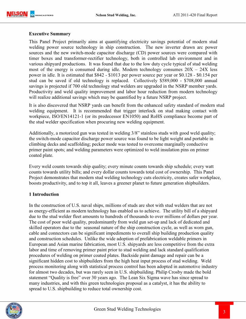
Figure 2. Weld counter mounted on weld cable
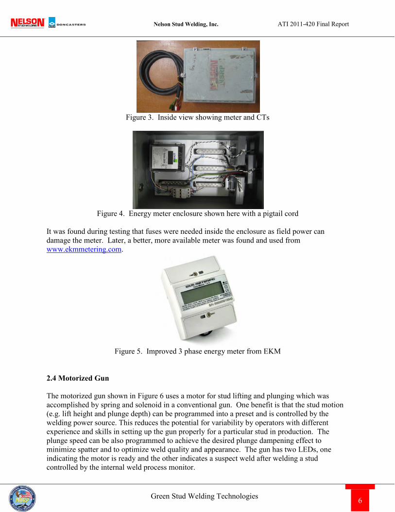
A commercially available counter was used in conjunction with a magnetic reed switch to count the number of welds performed on any welder. The counter and reed switch were mounted in an enclosure and strapped to the weld cable for sensing current. 2.3 Weld Energy Meters Three phase 480VAC energy usage was measured using a commercially available energy meter system. This consisted of a control box and CTs for measuring current. These devices were mounted in a larger enclosure to be installed in-line with each welder.
Nelson Stud Welding, Inc. ATI 2011-420 Final Report
6 Green Stud Welding Technologies
Figure 3. Inside view showing meter and CTs
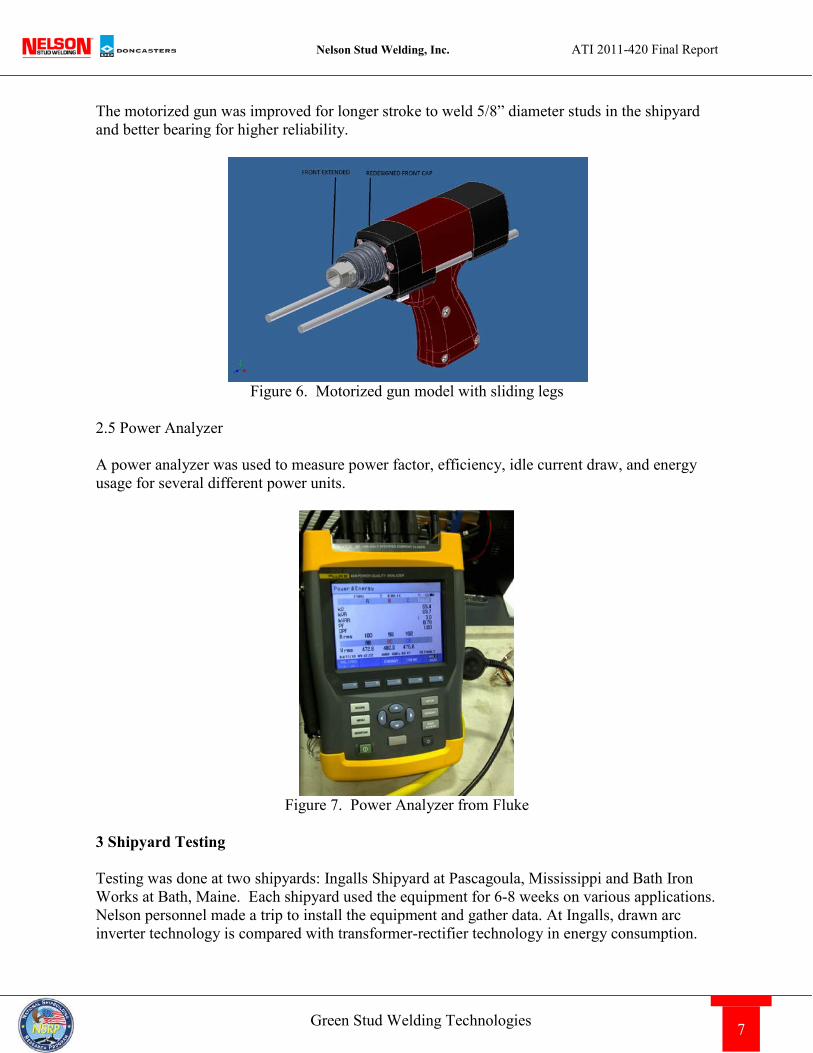
Figure 4. Energy meter enclosure shown here with a pigtail cord
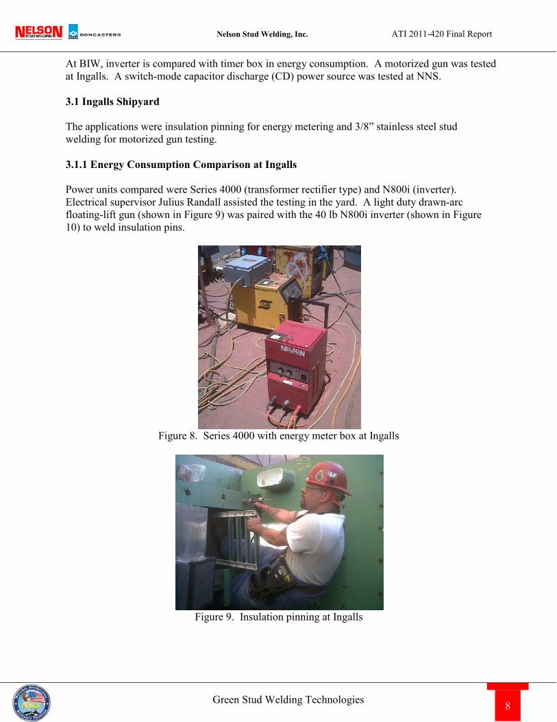
It was found during testing that fuses were needed inside the enclosure as field power can damage the meter. Later, a better, more available meter was found and used from www.ekmmetering.com.
Figure 5. Improved 3 phase energy meter from EKM
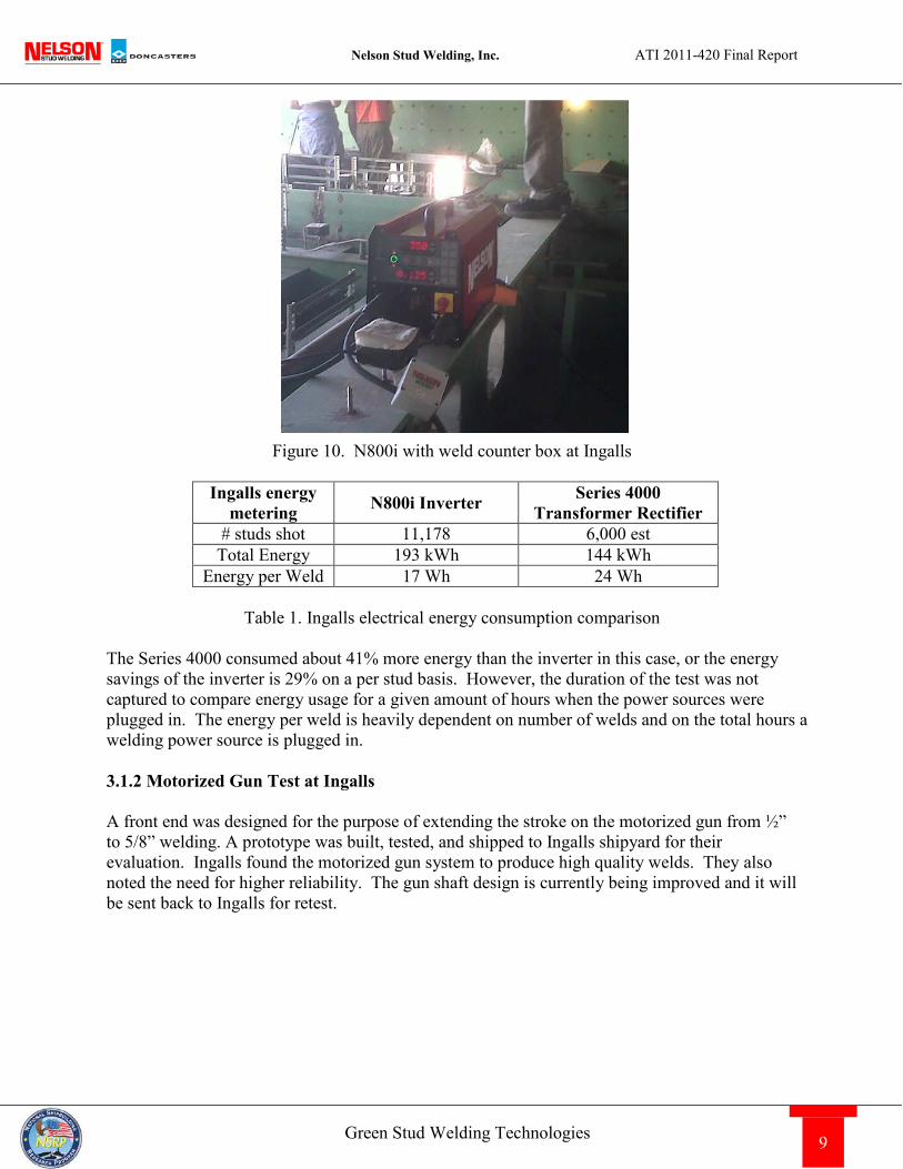
2.4 Motorized Gun The motorized gun shown in Figure 6 uses a motor for stud lifting and plunging which was accomplished by spring and solenoid in a conventional gun. One benefit is that the stud motion (e.g. lift height and plunge depth) can be programmed into a preset and is controlled by the welding power source. This reduces the potential for variability by operators with different experience and skills in setting up the gun properly for a particular stud in production. The plunge speed can be also programmed to achieve the desired plunge dampening effect to minimize spatter and to optimize weld quality and appearance. The gun has two LEDs, one indicating the motor is ready and the other indicates a suspect weld after welding a stud controlled by the internal weld process monitor.
Nelson Stud Welding, Inc. ATI 2011-420 Final Report
7 Green Stud Welding Technologies
The motorized gun was improved for longer stroke to weld 5/8” diameter studs in the shipyard and better bearing for higher reliability.
Figure 6. Motorized gun model with sliding legs
2.5 Power Analyzer A power analyzer was used to measure power factor, efficiency, idle current draw, and energy usage for several different power units.
Figure 7. Power Analyzer from Fluke
3 Shipyard Testing Testing was done at two shipyards: Ingalls Shipyard at Pascagoula, Mississippi and Bath Iron Works at Bath, Maine. Each shipyard used the equipment for 6-8 weeks on various applications. Nelson personnel made a trip to install the equipment and gather data. At Ingalls, drawn arc inverter technology is compared with transformer-rectifier technology in energy consumption.
Nelson Stud Welding, Inc. ATI 2011-420 Final Report
8 Green Stud Welding Technologies
At BIW, inverter is compared with timer box in energy consumption. A motorized gun was tested at Ingalls. A switch-mode capacitor discharge (CD) power source was tested at NNS. 3.1 Ingalls Shipyard The applications were insulation pinning for energy metering and 3/8” stainless steel stud welding for motorized gun testing. 3.1.1 Energy Consumption Comparison at Ingalls Power units compared were Series 4000 (transformer rectifier type) and N800i (inverter). Electrical supervisor Julius Randall assisted the testing in the yard. A light duty drawn-arc floating-lift gun (shown in Figure 9) was paired with the 40 lb N800i inverter (shown in Figure 10) to weld insulation pins.
Figure 8. Series 4000 with energy meter box at Ingalls
Figure 9. Insulation pinning at Ingalls
Nelson Stud Welding, Inc. ATI 2011-420 Final Report
9 Green Stud Welding Technologies
Figure 10. N800i with weld counter box at Ingalls
Ingalls energy
metering N800i Inverter Series 4000 Transformer Rectifier
# studs shot 11,178 6,000 est Total Energy 193 kWh 144 kWh
Energy per Weld 17 Wh 24 Wh
Table 1. Ingalls electrical energy consumption comparison The Series 4000 consumed about 41% more energy than the inverter in this case, or the energy savings of the inverter is 29% on a per stud basis. However, the duration of the test was not captured to compare energy usage for a given amount of hours when the power sources were plugged in. The energy per weld is heavily dependent on number of welds and on the total hours a welding power source is plugged in. 3.1.2 Motorized Gun Test at Ingalls A front end was designed for the purpose of extending the stroke on the motorized gun from ½” to 5/8” welding. A prototype was built, tested, and shipped to Ingalls shipyard for their evaluation. Ingalls found the motorized gun system to produce high quality welds. They also noted the need for higher reliability. The gun shaft design is currently being improved and it will be sent back to Ingalls for retest.
Nelson Stud Welding, Inc. ATI 2011-420 Final Report
10 Green Stud Welding Technologies
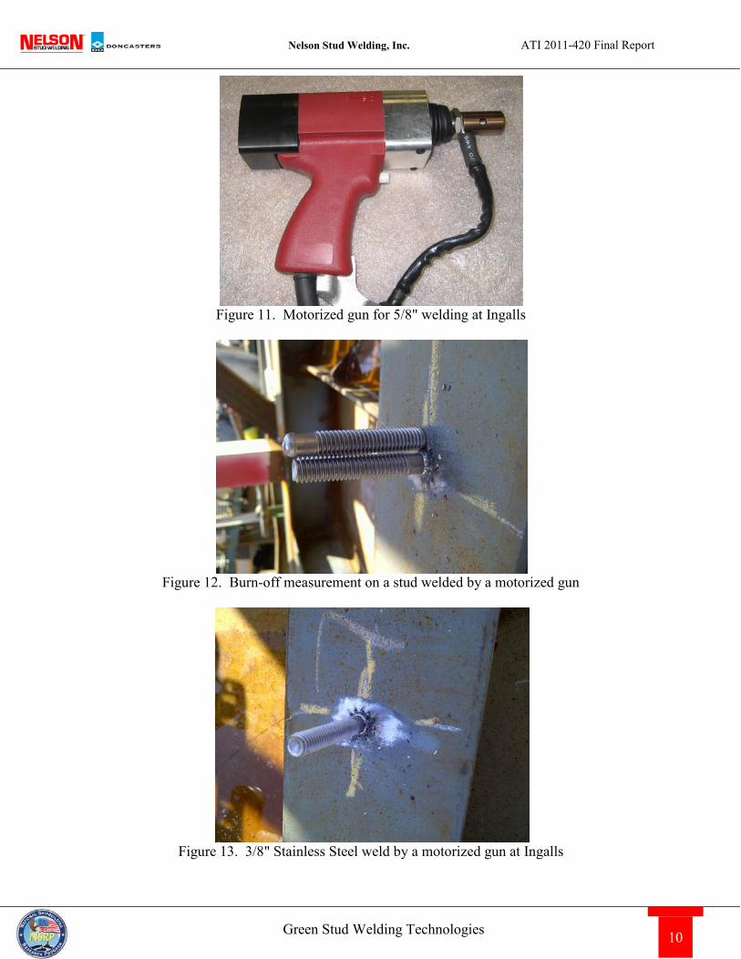
Figure 11. Motorized gun for 5/8" welding at Ingalls
Figure 12. Burn-off measurement on a stud welded by a motorized gun
Figure 13. 3/8" Stainless Steel weld by a motorized gun at Ingalls
Nelson Stud Welding, Inc. ATI 2011-420 Final Report
11 Green Stud Welding Technologies
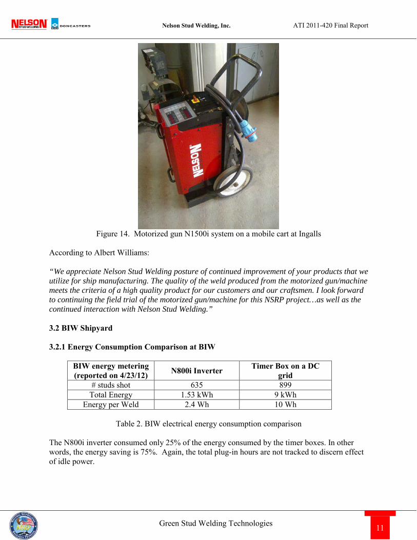
Figure 14. Motorized gun N1500i system on a mobile cart at Ingalls
According to Albert Williams: “We appreciate Nelson Stud Welding posture of continued improvement of your products that we utilize for ship manufacturing. The quality of the weld produced from the motorized gun/machine meets the criteria of a high quality product for our customers and our craftsmen. I look forward to continuing the field trial of the motorized gun/machine for this NSRP project…as well as the continued interaction with Nelson Stud Welding.” 3.2 BIW Shipyard 3.2.1 Energy Consumption Comparison at BIW
BIW energy metering (reported on 4/23/12) N800i Inverter Timer Box on a DC
grid # studs shot 635 899
Total Energy 1.53 kWh 9 kWh Energy per Weld 2.4 Wh 10 Wh
Table 2. BIW electrical energy consumption comparison
The N800i inverter consumed only 25% of the energy consumed by the timer boxes. In other words, the energy saving is 75%. Again, the total plug-in hours are not tracked to discern effect of idle power.
Nelson Stud Welding, Inc. ATI 2011-420 Final Report
12 Green Stud Welding Technologies
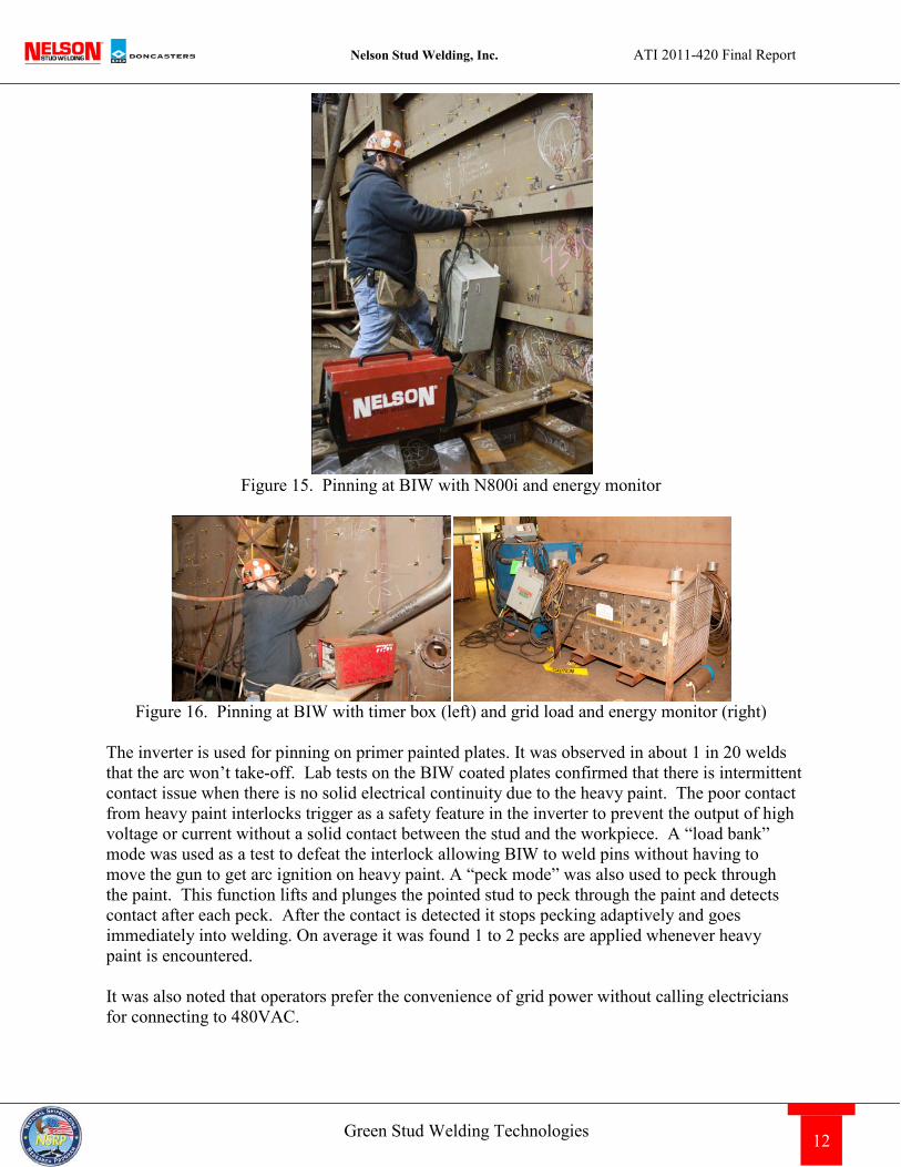
Figure 15. Pinning at BIW with N800i and energy monitor
Figure 16. Pinning at BIW with timer box (left) and grid load and energy monitor (right)
The inverter is used for pinning on primer painted plates. It was observed in about 1 in 20 welds that the arc won’t take-off. Lab tests on the BIW coated plates confirmed that there is intermittent contact issue when there is no solid electrical continuity due to the heavy paint. The poor contact from heavy paint interlocks trigger as a safety feature in the inverter to prevent the output of high voltage or current without a solid contact between the stud and the workpiece. A “load bank” mode was used as a test to defeat the interlock allowing BIW to weld pins without having to move the gun to get arc ignition on heavy paint. A “peck mode” was also used to peck through the paint. This function lifts and plunges the pointed stud to peck through the paint and detects contact after each peck. After the contact is detected it stops pecking adaptively and goes immediately into welding. On average it was found 1 to 2 pecks are applied whenever heavy paint is encountered. It was also noted that operators prefer the convenience of grid power without calling electricians for connecting to 480VAC.
Nelson Stud Welding, Inc. ATI 2011-420 Final Report
13 Green Stud Welding Technologies
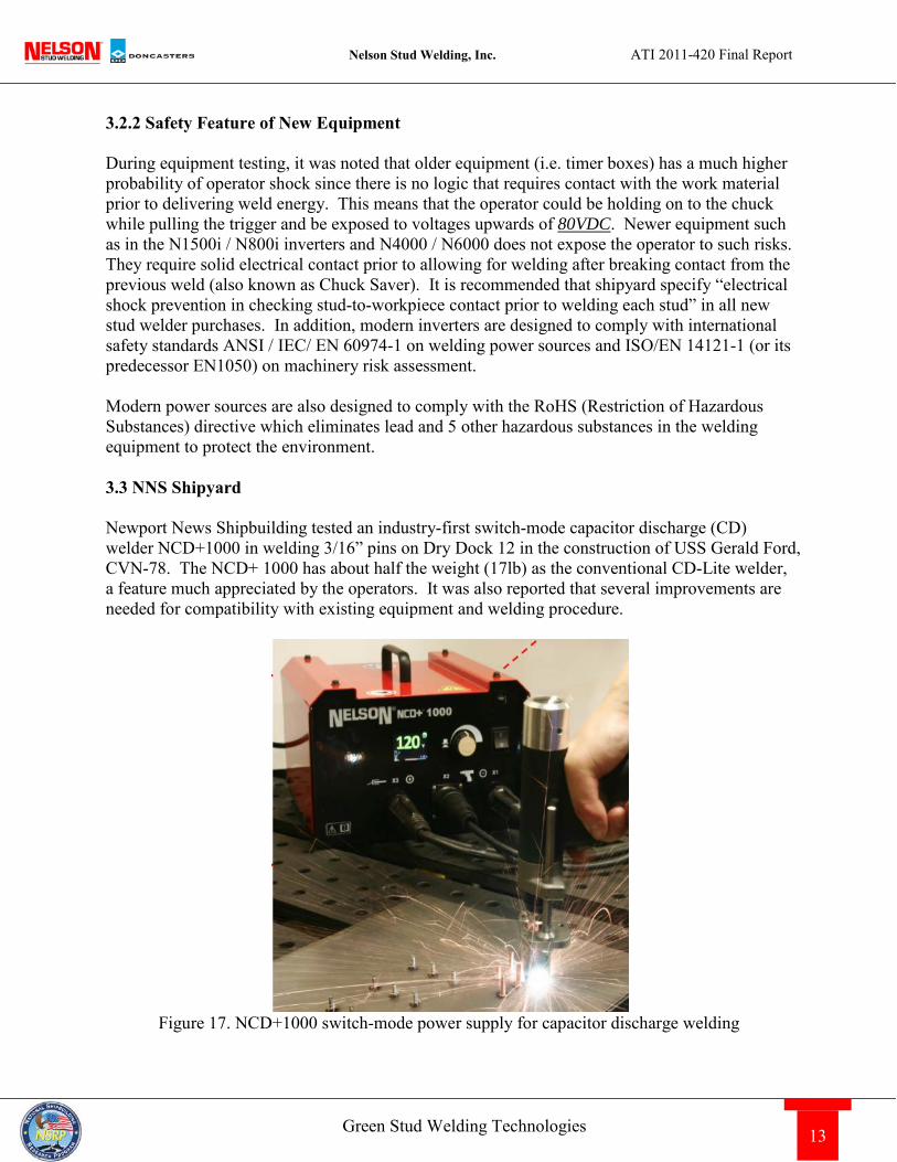
3.2.2 Safety Feature of New Equipment During equipment testing, it was noted that older equipment (i.e. timer boxes) has a much higher probability of operator shock since there is no logic that requires contact with the work material prior to delivering weld energy. This means that the operator could be holding on to the chuck while pulling the trigger and be exposed to voltages upwards of 80VDC. Newer equipment such as in the N1500i / N800i inverters and N4000 / N6000 does not expose the operator to such risks. They require solid electrical contact prior to allowing for welding after breaking contact from the previous weld (also known as Chuck Saver). It is recommended that shipyard specify “electrical shock prevention in checking stud-to-workpiece contact prior to welding each stud” in all new stud welder purchases. In addition, modern inverters are designed to comply with international safety standards ANSI / IEC/ EN 60974-1 on welding power sources and ISO/EN 14121-1 (or its predecessor EN1050) on machinery risk assessment. Modern power sources are also designed to comply with the RoHS (Restriction of Hazardous Substances) directive which eliminates lead and 5 other hazardous substances in the welding equipment to protect the environment. 3.3 NNS Shipyard Newport News Shipbuilding tested an industry-first switch-mode capacitor discharge (CD) welder NCD+1000 in welding 3/16” pins on Dry Dock 12 in the construction of USS Gerald Ford, CVN-78. The NCD+ 1000 has about half the weight (17lb) as the conventional CD-Lite welder, a feature much appreciated by the operators. It was also reported that several improvements are needed for compatibility with existing equipment and welding procedure.
Figure 17. NCD+1000 switch-mode power supply for capacitor discharge welding
Nelson Stud Welding, Inc. ATI 2011-420 Final Report
14 Green Stud Welding Technologies
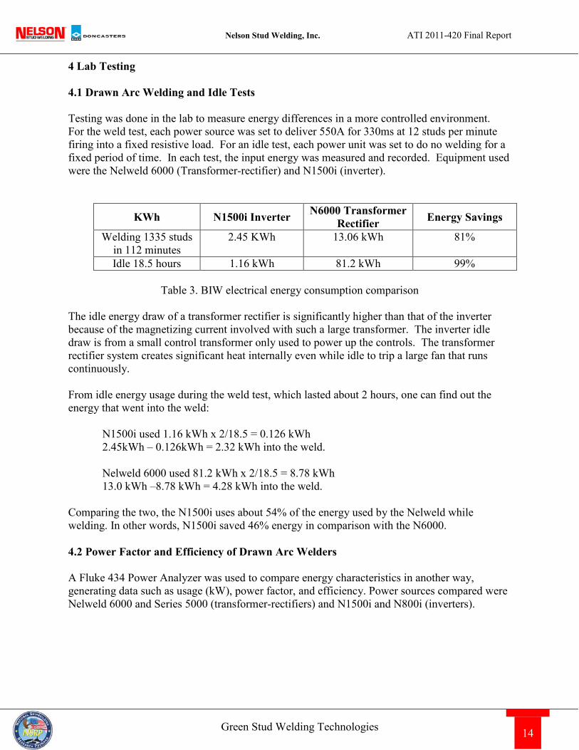
4 Lab Testing 4.1 Drawn Arc Welding and Idle Tests Testing was done in the lab to measure energy differences in a more controlled environment. For the weld test, each power source was set to deliver 550A for 330ms at 12 studs per minute firing into a fixed resistive load. For an idle test, each power unit was set to do no welding for a fixed period of time. In each test, the input energy was measured and recorded. Equipment used were the Nelweld 6000 (Transformer-rectifier) and N1500i (inverter).
KWh N1500i Inverter N6000 Transformer Rectifier Energy Savings
Welding 1335 studs in 112 minutes
2.45 KWh 13.06 kWh 81%
Idle 18.5 hours 1.16 kWh 81.2 kWh 99%
Table 3. BIW electrical energy consumption comparison The idle energy draw of a transformer rectifier is significantly higher than that of the inverter because of the magnetizing current involved with such a large transformer. The inverter idle draw is from a small control transformer only used to power up the controls. The transformer rectifier system creates significant heat internally even while idle to trip a large fan that runs continuously. From idle energy usage during the weld test, which lasted about 2 hours, one can find out the energy that went into the weld:
N1500i used 1.16 kWh x 2/18.5 = 0.126 kWh 2.45kWh – 0.126kWh = 2.32 kWh into the weld.
Nelweld 6000 used 81.2 kWh x 2/18.5 = 8.78 kWh 13.0 kWh –8.78 kWh = 4.28 kWh into the weld.
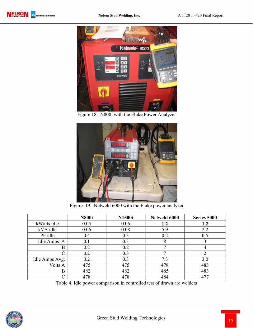
Comparing the two, the N1500i uses about 54% of the energy used by the Nelweld while welding. In other words, N1500i saved 46% energy in comparison with the N6000. 4.2 Power Factor and Efficiency of Drawn Arc Welders A Fluke 434 Power Analyzer was used to compare energy characteristics in another way, generating data such as usage (kW), power factor, and efficiency. Power sources compared were Nelweld 6000 and Series 5000 (transformer-rectifiers) and N1500i and N800i (inverters).
Nelson Stud Welding, Inc. ATI 2011-420 Final Report
15 Green Stud Welding Technologies
Figure 18. N800i with the Fluke Power Analyzer
Figure 19. Nelweld 6000 with the Fluke power analyzer
N800i N1500i Nelweld 6000 Series 5000
kWatts idle 0.05 0.06 1.2 1.2 kVA idle 0.06 0.08 5.9 2.2 PF idle 0.4 0.3 0.2 0.5
Idle Amps A 0.1 0.3 8 3 B 0.2 0.2 7 4 C 0.2 0.3 7 2
Idle Amps Avg. 0.2 0.3 7.3 3.0 Volts A 475 475 478 483
B 482 482 485 483 C 478 478 484 477
Table 4. Idle power comparison in controlled test of drawn arc welders
Nelson Stud Welding, Inc. ATI 2011-420 Final Report
16 Green Stud Welding Technologies
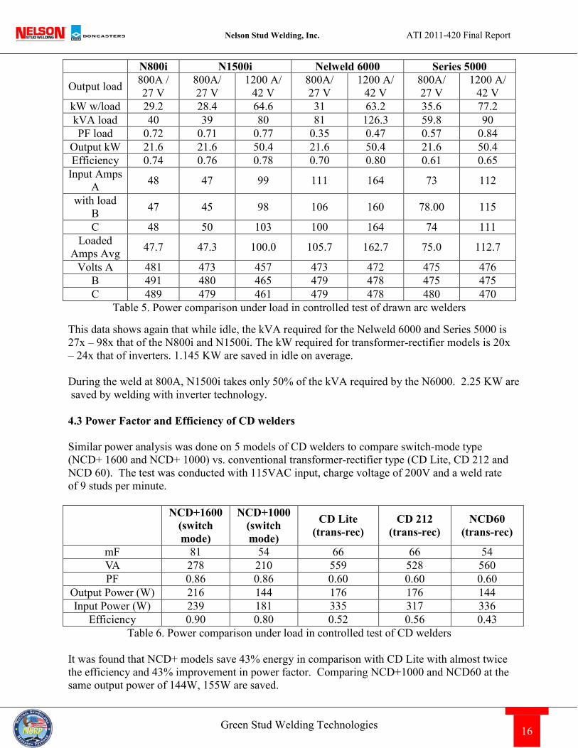
N800i N1500i Nelweld 6000 Series 5000
Output load 800A / 27 V
800A/ 27 V
1200 A/ 42 V
800A/ 27 V
1200 A/ 42 V
800A/ 27 V
1200 A/ 42 V
kW w/load 29.2 28.4 64.6 31 63.2 35.6 77.2 kVA load 40 39 80 81 126.3 59.8 90 PF load 0.72 0.71 0.77 0.35 0.47 0.57 0.84
Output kW 21.6 21.6 50.4 21.6 50.4 21.6 50.4 Efficiency 0.74 0.76 0.78 0.70 0.80 0.61 0.65
Input Amps A 48 47 99 111 164 73 112
with load B 47 45 98 106 160 78.00 115
C 48 50 103 100 164 74 111 Loaded
Amps Avg 47.7 47.3 100.0 105.7 162.7 75.0 112.7
Volts A 481 473 457 473 472 475 476 B 491 480 465 479 478 475 475 C 489 479 461 479 478 480 470
Table 5. Power comparison under load in controlled test of drawn arc welders
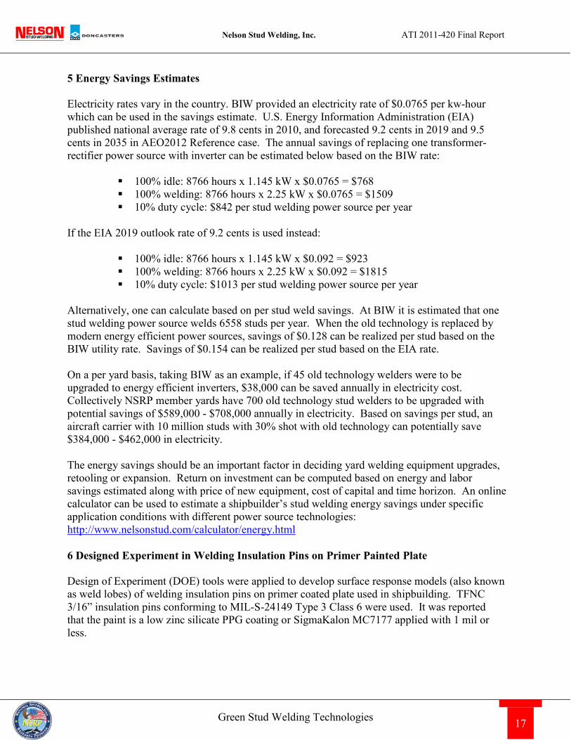
This data shows again that while idle, the kVA required for the Nelweld 6000 and Series 5000 is 27x – 98x that of the N800i and N1500i. The kW required for transformer-rectifier models is 20x – 24x that of inverters. 1.145 KW are saved in idle on average. During the weld at 800A, N1500i takes only 50% of the kVA required by the N6000. 2.25 KW are saved by welding with inverter technology. 4.3 Power Factor and Efficiency of CD welders Similar power analysis was done on 5 models of CD welders to compare switch-mode type (NCD+ 1600 and NCD+ 1000) vs. conventional transformer-rectifier type (CD Lite, CD 212 and NCD 60). The test was conducted with 115VAC input, charge voltage of 200V and a weld rate of 9 studs per minute.
NCD+1600
(switch mode)
NCD+1000 (switch mode)
CD Lite (trans-rec)
CD 212 (trans-rec)
NCD60 (trans-rec)
mF 81 54 66 66 54 VA 278 210 559 528 560 PF 0.86 0.86 0.60 0.60 0.60
Output Power (W) 216 144 176 176 144 Input Power (W) 239 181 335 317 336
Efficiency 0.90 0.80 0.52 0.56 0.43 Table 6. Power comparison under load in controlled test of CD welders
It was found that NCD+ models save 43% energy in comparison with CD Lite with almost twice the efficiency and 43% improvement in power factor. Comparing NCD+1000 and NCD60 at the same output power of 144W, 155W are saved.
Nelson Stud Welding, Inc. ATI 2011-420 Final Report
17 Green Stud Welding Technologies
5 Energy Savings Estimates Electricity rates vary in the country. BIW provided an electricity rate of $0.0765 per kw-hour which can be used in the savings estimate. U.S. Energy Information Administration (EIA) published national average rate of 9.8 cents in 2010, and forecasted 9.2 cents in 2019 and 9.5 cents in 2035 in AEO2012 Reference case. The annual savings of replacing one transformer-rectifier power source with inverter can be estimated below based on the BIW rate:
100% idle: 8766 hours x 1.145 kW x $0.0765 = $768 100% welding: 8766 hours x 2.25 kW x $0.0765 = $1509 10% duty cycle: $842 per stud welding power source per year
If the EIA 2019 outlook rate of 9.2 cents is used instead:
100% idle: 8766 hours x 1.145 kW x $0.092 = $923 100% welding: 8766 hours x 2.25 kW x $0.092 = $1815 10% duty cycle: $1013 per stud welding power source per year
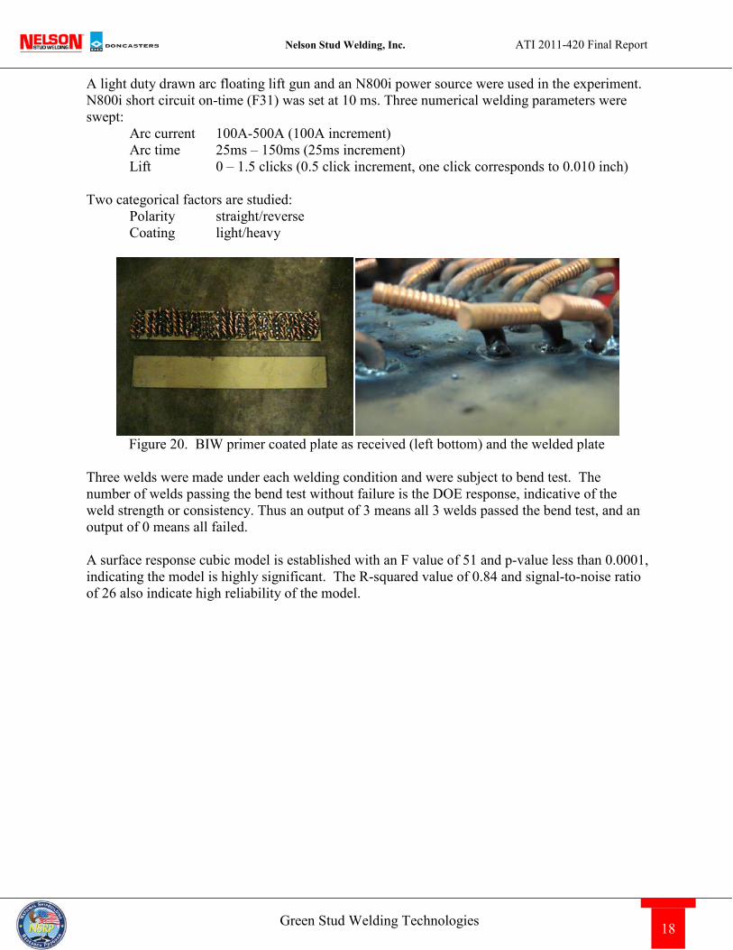
Alternatively, one can calculate based on per stud weld savings. At BIW it is estimated that one stud welding power source welds 6558 studs per year. When the old technology is replaced by modern energy efficient power sources, savings of $0.128 can be realized per stud based on the BIW utility rate. Savings of $0.154 can be realized per stud based on the EIA rate. On a per yard basis, taking BIW as an example, if 45 old technology welders were to be upgraded to energy efficient inverters, $38,000 can be saved annually in electricity cost. Collectively NSRP member yards have 700 old technology stud welders to be upgraded with potential savings of $589,000 - $708,000 annually in electricity. Based on savings per stud, an aircraft carrier with 10 million studs with 30% shot with old technology can potentially save $384,000 - $462,000 in electricity. The energy savings should be an important factor in deciding yard welding equipment upgrades, retooling or expansion. Return on investment can be computed based on energy and labor savings estimated along with price of new equipment, cost of capital and time horizon. An online calculator can be used to estimate a shipbuilder’s stud welding energy savings under specific application conditions with different power source technologies: http://www.nelsonstud.com/calculator/energy.html 6 Designed Experiment in Welding Insulation Pins on Primer Painted Plate Design of Experiment (DOE) tools were applied to develop surface response models (also known as weld lobes) of welding insulation pins on primer coated plate used in shipbuilding. TFNC 3/16” insulation pins conforming to MIL-S-24149 Type 3 Class 6 were used. It was reported that the paint is a low zinc silicate PPG coating or SigmaKalon MC7177 applied with 1 mil or less.
Nelson Stud Welding, Inc. ATI 2011-420 Final Report
18 Green Stud Welding Technologies
A light duty drawn arc floating lift gun and an N800i power source were used in the experiment. N800i short circuit on-time (F31) was set at 10 ms. Three numerical welding parameters were swept: Arc current 100A-500A (100A increment) Arc time 25ms – 150ms (25ms increment) Lift 0 – 1.5 clicks (0.5 click increment, one click corresponds to 0.010 inch) Two categorical factors are studied: Polarity straight/reverse Coating light/heavy
Figure 20. BIW primer coated plate as received (left bottom) and the welded plate
Three welds were made under each welding condition and were subject to bend test. The number of welds passing the bend test without failure is the DOE response, indicative of the weld strength or consistency. Thus an output of 3 means all 3 welds passed the bend test, and an output of 0 means all failed. A surface response cubic model is established with an F value of 51 and p-value less than 0.0001, indicating the model is highly significant. The R-squared value of 0.84 and signal-to-noise ratio of 26 also indicate high reliability of the model.
Nelson Stud Welding, Inc. ATI 2011-420 Final Report
19 Green Stud Welding Technologies
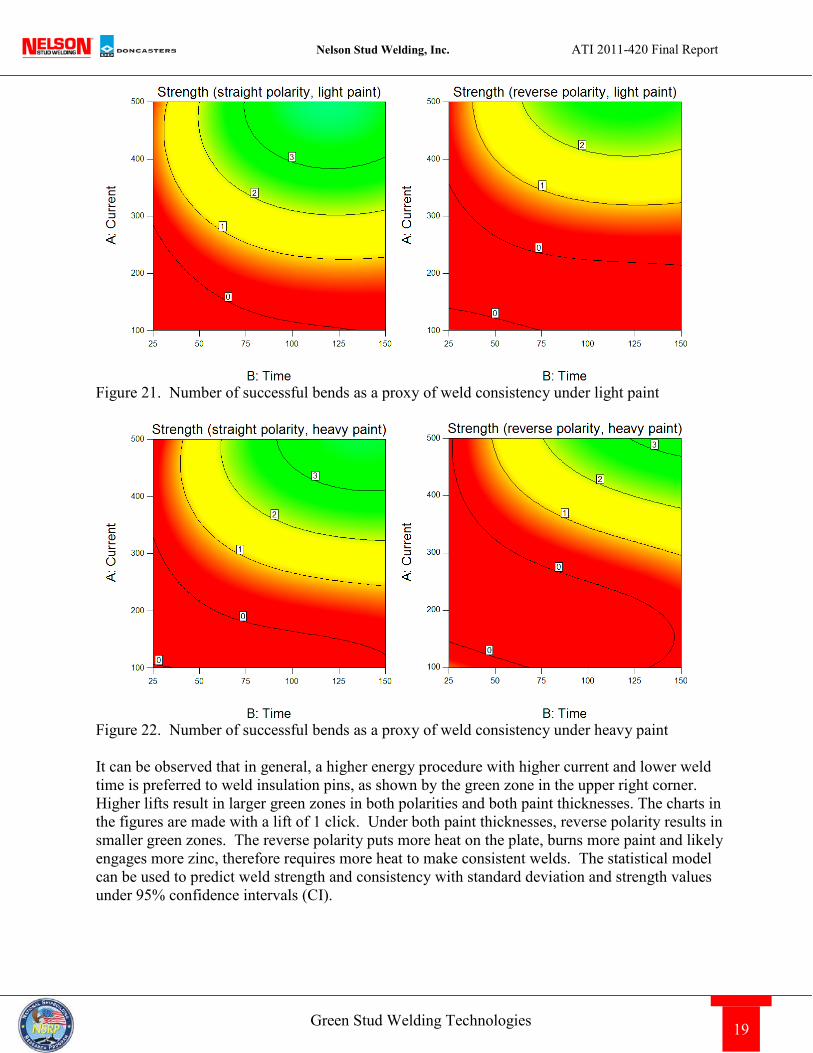
Figure 21. Number of successful bends as a proxy of weld consistency under light paint
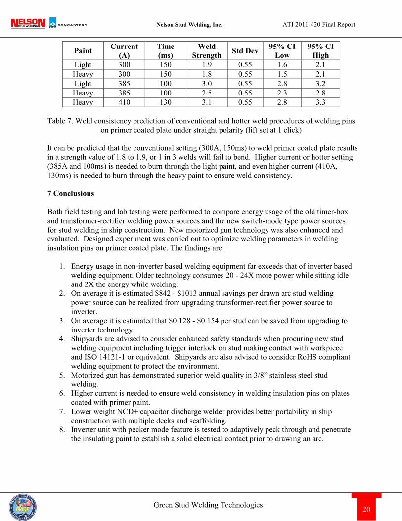
Figure 22. Number of successful bends as a proxy of weld consistency under heavy paint It can be observed that in general, a higher energy procedure with higher current and lower weld time is preferred to weld insulation pins, as shown by the green zone in the upper right corner. Higher lifts result in larger green zones in both polarities and both paint thicknesses. The charts in the figures are made with a lift of 1 click. Under both paint thicknesses, reverse polarity results in smaller green zones. The reverse polarity puts more heat on the plate, burns more paint and likely engages more zinc, therefore requires more heat to make consistent welds. The statistical model can be used to predict weld strength and consistency with standard deviation and strength values under 95% confidence intervals (CI).
Nelson Stud Welding, Inc. ATI 2011-420 Final Report
20 Green Stud Welding Technologies
Paint Current (A)
Time (ms)
Weld Strength Std Dev 95% CI
Low 95% CI
High Light 300 150 1.9 0.55 1.6 2.1 Heavy 300 150 1.8 0.55 1.5 2.1 Light 385 100 3.0 0.55 2.8 3.2 Heavy 385 100 2.5 0.55 2.3 2.8 Heavy 410 130 3.1 0.55 2.8 3.3
Table 7. Weld consistency prediction of conventional and hotter weld procedures of welding pins
on primer coated plate under straight polarity (lift set at 1 click) It can be predicted that the conventional setting (300A, 150ms) to weld primer coated plate results in a strength value of 1.8 to 1.9, or 1 in 3 welds will fail to bend. Higher current or hotter setting (385A and 100ms) is needed to burn through the light paint, and even higher current (410A, 130ms) is needed to burn through the heavy paint to ensure weld consistency. 7 Conclusions Both field testing and lab testing were performed to compare energy usage of the old timer-box and transformer-rectifier welding power sources and the new switch-mode type power sources for stud welding in ship construction. New motorized gun technology was also enhanced and evaluated. Designed experiment was carried out to optimize welding parameters in welding insulation pins on primer coated plate. The findings are:
1. Energy usage in non-inverter based welding equipment far exceeds that of inverter based welding equipment. Older technology consumes 20 - 24X more power while sitting idle and 2X the energy while welding.
2. On average it is estimated $842 - $1013 annual savings per drawn arc stud welding power source can be realized from upgrading transformer-rectifier power source to inverter.
3. On average it is estimated that $0.128 - $0.154 per stud can be saved from upgrading to inverter technology.
4. Shipyards are advised to consider enhanced safety standards when procuring new stud welding equipment including trigger interlock on stud making contact with workpiece and ISO 14121-1 or equivalent. Shipyards are also advised to consider RoHS compliant welding equipment to protect the environment.
5. Motorized gun has demonstrated superior weld quality in 3/8” stainless steel stud welding.
6. Higher current is needed to ensure weld consistency in welding insulation pins on plates coated with primer paint.
7. Lower weight NCD+ capacitor discharge welder provides better portability in ship construction with multiple decks and scaffolding.
8. Inverter unit with pecker mode feature is tested to adaptively peck through and penetrate the insulating paint to establish a solid electrical contact prior to drawing an arc.
Nelson Stud Welding, Inc. ATI 2011-420 Final Report
21 Green Stud Welding Technologies
8 Future Work During the one year time frame the project focus was placed on measureable “hard savings” in electricity costs. Labor cost reduction, downtime reduction, maintenance cost reduction and efficiency and productivity improvements are not measured. The full potential of modern stud welding equipment to reduce total cost of ownership of ship construction would require the evaluation of:
1. Motorized gun in improving weld repeatability and reducing inconsistent weld quality resulting from gun setup error or novice operators;
2. Weld process monitor in applying lean sigma and statistical process control principles in ship construction;
3. Weld equipment monitor (weld gun motion, chuck and weld cable and connector wear) in assisting preventative maintenance and ensure production uptime;
4. Pulse waveform in reducing heat input and distortion; 5. Pulse waveform and constant energy process control in welding primer coated steels;
9 References
1. Hsu, C. et al, Stud Welding Technologies for a Greener Future, AWS Welding Journal, October 2010 pp. 39-42.
2. Cooper R.B. et al, NSRP 0408 Fundamentals of Arc Stud Welding: An Interactive Multimedia lesson for Shipyard Training, U.S. Department of the Navy Carderock Division, Naval Surface Warfare Center, November 1993.
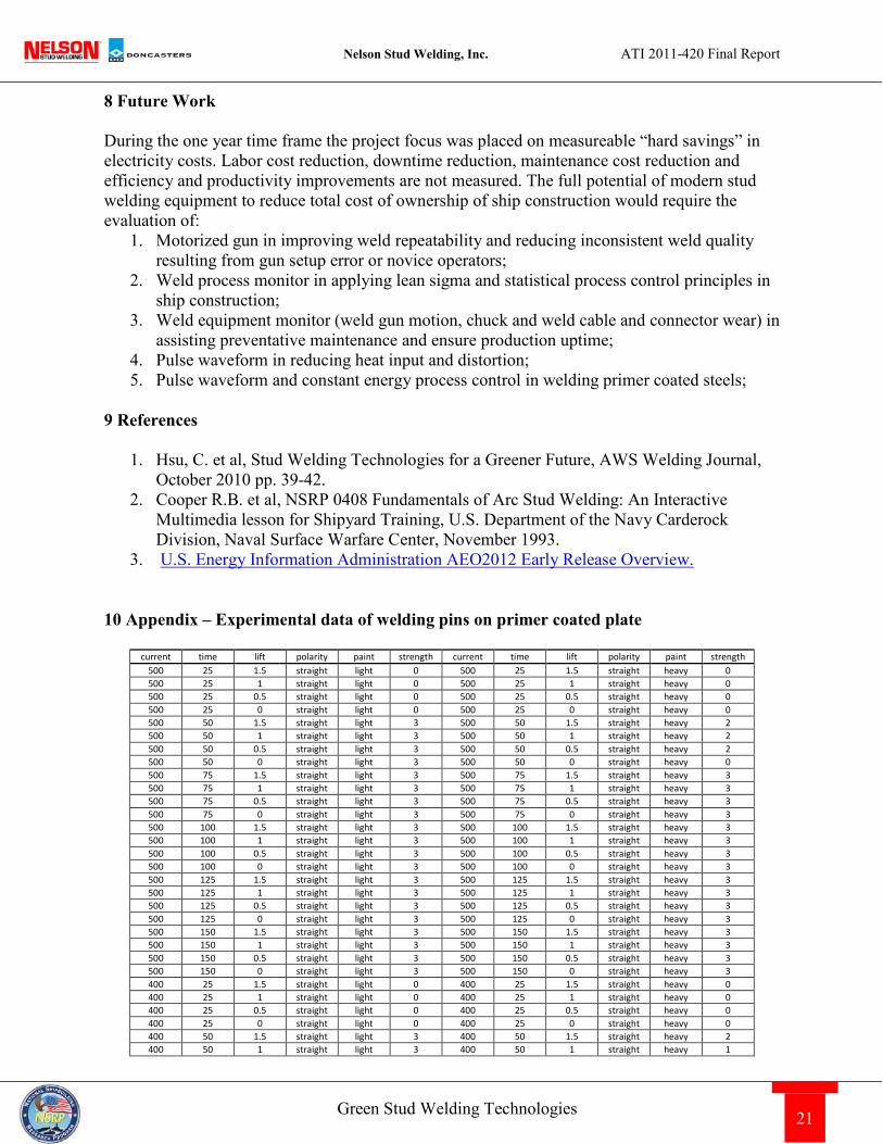
3. U.S. Energy Information Administration AEO2012 Early Release Overview. 10 Appendix – Experimental data of welding pins on primer coated plate
current time lift polarity paint strength current time lift polarity paint strength 500 25 1.5 straight light 0 500 25 1.5 straight heavy 0 500 25 1 straight light 0 500 25 1 straight heavy 0 500 25 0.5 straight light 0 500 25 0.5 straight heavy 0 500 25 0 straight light 0 500 25 0 straight heavy 0 500 50 1.5 straight light 3 500 50 1.5 straight heavy 2 500 50 1 straight light 3 500 50 1 straight heavy 2 500 50 0.5 straight light 3 500 50 0.5 straight heavy 2 500 50 0 straight light 3 500 50 0 straight heavy 0 500 75 1.5 straight light 3 500 75 1.5 straight heavy 3 500 75 1 straight light 3 500 75 1 straight heavy 3 500 75 0.5 straight light 3 500 75 0.5 straight heavy 3 500 75 0 straight light 3 500 75 0 straight heavy 3 500 100 1.5 straight light 3 500 100 1.5 straight heavy 3 500 100 1 straight light 3 500 100 1 straight heavy 3 500 100 0.5 straight light 3 500 100 0.5 straight heavy 3 500 100 0 straight light 3 500 100 0 straight heavy 3 500 125 1.5 straight light 3 500 125 1.5 straight heavy 3 500 125 1 straight light 3 500 125 1 straight heavy 3 500 125 0.5 straight light 3 500 125 0.5 straight heavy 3 500 125 0 straight light 3 500 125 0 straight heavy 3 500 150 1.5 straight light 3 500 150 1.5 straight heavy 3 500 150 1 straight light 3 500 150 1 straight heavy 3 500 150 0.5 straight light 3 500 150 0.5 straight heavy 3 500 150 0 straight light 3 500 150 0 straight heavy 3 400 25 1.5 straight light 0 400 25 1.5 straight heavy 0 400 25 1 straight light 0 400 25 1 straight heavy 0 400 25 0.5 straight light 0 400 25 0.5 straight heavy 0 400 25 0 straight light 0 400 25 0 straight heavy 0 400 50 1.5 straight light 3 400 50 1.5 straight heavy 2 400 50 1 straight light 3 400 50 1 straight heavy 1
Nelson Stud Welding, Inc. ATI 2011-420 Final Report
22 Green Stud Welding Technologies
400 50 0.5 straight light 1 400 50 0.5 straight heavy 0 400 50 0 straight light 2 400 50 0 straight heavy 0 400 75 1.5 straight light 3 400 75 1.5 straight heavy 3 400 75 1 straight light 3 400 75 1 straight heavy 3 400 75 0.5 straight light 3 400 75 0.5 straight heavy 2 400 75 0 straight light 2 400 75 0 straight heavy 3 400 100 1.5 straight light 3 400 100 1.5 straight heavy 3 400 100 1 straight light 3 400 100 1 straight heavy 3 400 100 0.5 straight light 3 400 100 0.5 straight heavy 3 400 100 0 straight light 3 400 100 0 straight heavy 2.5 400 125 1.5 straight light 3 400 125 1.5 straight heavy 3 400 125 1 straight light 3 400 125 1 straight heavy 3 400 125 0.5 straight light 3 400 125 0.5 straight heavy 3 400 125 0 straight light 3 400 125 0 straight heavy 2 400 150 1.5 straight light 3 400 150 1.5 straight heavy 3 400 150 1 straight light 3 400 150 1 straight heavy 3 400 150 0.5 straight light 3 400 150 0.5 straight heavy 3 400 150 0 straight light 3 400 150 0 straight heavy 3 300 25 1.5 straight light 0 300 25 1.5 straight heavy 0 300 25 1 straight light 0 300 25 1 straight heavy 0 300 25 0.5 straight light 0 300 25 0.5 straight heavy 0 300 25 0 straight light 0 300 25 0 straight heavy 0 300 50 1.5 straight light 0 300 50 1.5 straight heavy 0 300 50 1 straight light 0 300 50 1 straight heavy 0 300 50 0.5 straight light 0 300 50 0.5 straight heavy 0 300 50 0 straight light 0 300 50 0 straight heavy 0 300 75 1.5 straight light 3 300 75 1.5 straight heavy 1 300 75 1 straight light 2 300 75 1 straight heavy 1 300 75 0.5 straight light 1 300 75 0.5 straight heavy 1 300 75 0 straight light 0 300 75 0 straight heavy 0 300 100 1.5 straight light 3 300 100 1.5 straight heavy 2 300 100 1 straight light 2.5 300 100 1 straight heavy 0.5 300 100 0.5 straight light 2.5 300 100 0.5 straight heavy 0.5 300 100 0 straight light 1.5 300 100 0 straight heavy 0 300 125 1.5 straight light 3 300 125 1.5 straight heavy 3 300 125 1 straight light 3 300 125 1 straight heavy 3 300 125 0.5 straight light 3 300 125 0.5 straight heavy 2 300 125 0 straight light 3 300 125 0 straight heavy 0 300 150 1.5 straight light 3 300 150 1.5 straight heavy 3 300 150 1 straight light 3 300 150 1 straight heavy 3 300 150 0.5 straight light 3 300 150 0.5 straight heavy 3 300 150 0 straight light 2 300 150 0 straight heavy 0 200 25 1.5 straight light 0 200 25 1.5 straight heavy 0 200 25 1 straight light 0 200 25 1 straight heavy 0 200 25 0.5 straight light 0 200 25 0.5 straight heavy 0 200 25 0 straight light 0 200 25 0 straight heavy 0 200 50 1.5 straight light 0 200 50 1.5 straight heavy 0 200 50 1 straight light 0 200 50 1 straight heavy 0 200 50 0.5 straight light 0 200 50 0.5 straight heavy 0 200 50 0 straight light 0 200 50 0 straight heavy 0 200 75 1.5 straight light 0 200 75 1.5 straight heavy 0 200 75 1 straight light 0 200 75 1 straight heavy 0 200 75 0.5 straight light 0 200 75 0.5 straight heavy 0 200 75 0 straight light 0 200 75 0 straight heavy 0 200 100 1.5 straight light 0 200 100 1.5 straight heavy 0 200 100 1 straight light 0 200 100 1 straight heavy 0 200 100 0.5 straight light 0 200 100 0.5 straight heavy 0 200 100 0 straight light 0 200 100 0 straight heavy 0 200 125 1.5 straight light 0 200 125 1.5 straight heavy 0 200 125 1 straight light 0 200 125 1 straight heavy 0 200 125 0.5 straight light 0 200 125 0.5 straight heavy 0 200 125 0 straight light 0 200 125 0 straight heavy 0 200 150 1.5 straight light 0 200 150 1.5 straight heavy 0 200 150 1 straight light 0 200 150 1 straight heavy 0 200 150 0.5 straight light 0 200 150 0.5 straight heavy 0 200 150 0 straight light 0 200 150 0 straight heavy 0 100 25 1.5 straight light 0 100 25 1.5 straight heavy 0 100 25 1 straight light 0 100 25 1 straight heavy 0 100 25 0.5 straight light 0 100 25 0.5 straight heavy 0 100 25 0 straight light 0 100 25 0 straight heavy 0 100 50 1.5 straight light 0 100 50 1.5 straight heavy 0 100 50 1 straight light 0 100 50 1 straight heavy 0 100 50 0.5 straight light 0 100 50 0.5 straight heavy 0 100 50 0 straight light 0 100 50 0 straight heavy 0
Nelson Stud Welding, Inc. ATI 2011-420 Final Report
23 Green Stud Welding Technologies
100 75 1.5 straight light 0 100 75 1.5 straight heavy 0 100 75 1 straight light 0 100 75 1 straight heavy 0 100 75 0.5 straight light 0 100 75 0.5 straight heavy 0 100 75 0 straight light 0 100 75 0 straight heavy 0 100 100 1.5 straight light 0 100 100 1.5 straight heavy 0 100 100 1 straight light 0 100 100 1 straight heavy 0 100 100 0.5 straight light 0 100 100 0.5 straight heavy 0 100 100 0 straight light 0 100 100 0 straight heavy 0 100 125 1.5 straight light 0 100 125 1.5 straight heavy 0 100 125 1 straight light 0 100 125 1 straight heavy 0 100 125 0.5 straight light 0 100 125 0.5 straight heavy 0 100 125 0 straight light 0 100 125 0 straight heavy 0 100 150 1.5 straight light 0 100 150 1.5 straight heavy 0 100 150 1 straight light 0 100 150 1 straight heavy 0 100 150 0.5 straight light 0 100 150 0.5 straight heavy 0 100 150 0 straight light 0 100 150 0 straight heavy 0 500 25 1.5 reverse light 0 500 25 1.5 reverse heavy 0 500 25 1 reverse light 0 500 25 1 reverse heavy 0 500 25 0.5 reverse light 0 500 25 0.5 reverse heavy 0 500 25 0 reverse light 0 500 25 0 reverse heavy 0 500 50 1.5 reverse light 3 500 50 1.5 reverse heavy 0 500 50 1 reverse light 2 500 50 1 reverse heavy 0 500 50 0.5 reverse light 2 500 50 0.5 reverse heavy 0 500 50 0 reverse light 1 500 50 0 reverse heavy 0 500 75 1.5 reverse light 3 500 75 1.5 reverse heavy 3 500 75 1 reverse light 3 500 75 1 reverse heavy 3 500 75 0.5 reverse light 2 500 75 0.5 reverse heavy 3 500 75 0 reverse light 0 500 75 0 reverse heavy 2 500 100 1.5 reverse light 3 500 100 1.5 reverse heavy 3 500 100 1 reverse light 2.5 500 100 1 reverse heavy 3 500 100 0.5 reverse light 2.5 500 100 0.5 reverse heavy 3 500 100 0 reverse light 1.5 500 100 0 reverse heavy 2.5 500 125 1.5 reverse light 3 500 125 1.5 reverse heavy 3 500 125 1 reverse light 3 500 125 1 reverse heavy 3 500 125 0.5 reverse light 3 500 125 0.5 reverse heavy 3 500 125 0 reverse light 1 500 125 0 reverse heavy 3 500 150 1.5 reverse light 3 500 150 1.5 reverse heavy 3 500 150 1 reverse light 3 500 150 1 reverse heavy 3 500 150 0.5 reverse light 3 500 150 0.5 reverse heavy 3 500 150 0 reverse light 3 500 150 0 reverse heavy 3 400 25 1.5 reverse light 0 400 25 1.5 reverse heavy 0 400 25 1 reverse light 0 400 25 1 reverse heavy 0 400 25 0.5 reverse light 0 400 25 0.5 reverse heavy 0 400 25 0 reverse light 0 400 25 0 reverse heavy 0 400 50 1.5 reverse light 1 400 50 1.5 reverse heavy 0 400 50 1 reverse light 2 400 50 1 reverse heavy 0 400 50 0.5 reverse light 1 400 50 0.5 reverse heavy 0 400 50 0 reverse light 0 400 50 0 reverse heavy 0 400 75 1.5 reverse light 3 400 75 1.5 reverse heavy 0 400 75 1 reverse light 2 400 75 1 reverse heavy 0 400 75 0.5 reverse light 1 400 75 0.5 reverse heavy 0 400 75 0 reverse light 0 400 75 0 reverse heavy 0 400 100 1.5 reverse light 3 400 100 1.5 reverse heavy 1.5 400 100 1 reverse light 2.5 400 100 1 reverse heavy 1.5 400 100 0.5 reverse light 1 400 100 0.5 reverse heavy 1.5 400 100 0 reverse light 0.5 400 100 0 reverse heavy 1 400 125 1.5 reverse light 3 400 125 1.5 reverse heavy 3 400 125 1 reverse light 3 400 125 1 reverse heavy 3 400 125 0.5 reverse light 1 400 125 0.5 reverse heavy 2 400 125 0 reverse light 0 400 125 0 reverse heavy 3 400 150 1.5 reverse light 3 300 25 1.5 reverse heavy 0 400 150 1 reverse light 3 300 25 1 reverse heavy 0 400 150 0.5 reverse light 1 300 25 0.5 reverse heavy 0 400 150 0 reverse light 0 300 25 0 reverse heavy 0 300 25 1.5 reverse light 0 300 50 1.5 reverse heavy 0 300 25 1 reverse light 0 300 50 1 reverse heavy 0 300 25 0.5 reverse light 0 300 50 0.5 reverse heavy 0 300 25 0 reverse light 0 300 50 0 reverse heavy 0 300 50 1.5 reverse light 0 300 75 1.5 reverse heavy 0 300 50 1 reverse light 0 300 75 1 reverse heavy 0 300 50 0.5 reverse light 0 300 75 0.5 reverse heavy 0 300 50 0 reverse light 0 300 75 0 reverse heavy 0 300 75 1.5 reverse light 1 300 100 1.5 reverse heavy 0 300 75 1 reverse light 0 300 100 1 reverse heavy 0
Nelson Stud Welding, Inc. ATI 2011-420 Final Report
24 Green Stud Welding Technologies
300 75 0.5 reverse light 0 300 100 0.5 reverse heavy 0 300 75 0 reverse light 0 300 100 0 reverse heavy 0 300 100 1.5 reverse light 1 300 125 1.5 reverse heavy 1 300 100 1 reverse light 1.5 300 125 1 reverse heavy 0 300 100 0.5 reverse light 0.5 300 125 0.5 reverse heavy 0 300 100 0 reverse light 0 300 125 0 reverse heavy 0 300 125 1.5 reverse light 0 200 25 1.5 reverse heavy 0 300 125 1 reverse light 0 200 25 1 reverse heavy 0 300 125 0.5 reverse light 0 200 25 0.5 reverse heavy 0 300 125 0 reverse light 0 200 25 0 reverse heavy 0 300 150 1.5 reverse light 0 200 50 1.5 reverse heavy 0 300 150 1 reverse light 0 200 50 1 reverse heavy 0 300 150 0.5 reverse light 0 200 50 0.5 reverse heavy 0 300 150 0 reverse light 0 200 50 0 reverse heavy 0 200 25 1.5 reverse light 0 200 75 1.5 reverse heavy 0 200 25 1 reverse light 0 200 75 1 reverse heavy 0 200 25 0.5 reverse light 0 200 75 0.5 reverse heavy 0 200 25 0 reverse light 0 200 75 0 reverse heavy 0 200 50 1.5 reverse light 0 200 100 1.5 reverse heavy 0 200 50 1 reverse light 0 200 100 1 reverse heavy 0 200 50 0.5 reverse light 0 200 100 0.5 reverse heavy 0 200 50 0 reverse light 0 200 100 0 reverse heavy 0 200 75 1.5 reverse light 0 200 125 1.5 reverse heavy 0 200 75 1 reverse light 0 200 125 1 reverse heavy 0 200 75 0.5 reverse light 0 200 125 0.5 reverse heavy 0 200 75 0 reverse light 0 200 125 0 reverse heavy 0 200 100 1.5 reverse light 0 200 150 1.5 reverse heavy 0 200 100 1 reverse light 0 200 150 1 reverse heavy 0 200 100 0.5 reverse light 0 200 150 0.5 reverse heavy 0 200 100 0 reverse light 0 200 150 0 reverse heavy 0 200 125 1.5 reverse light 0 100 25 1.5 reverse heavy 0 200 125 1 reverse light 0 100 25 1 reverse heavy 0 200 125 0.5 reverse light 0 100 25 0.5 reverse heavy 0 200 125 0 reverse light 0 100 25 0 reverse heavy 0 200 150 1.5 reverse light 0 100 50 1.5 reverse heavy 0 200 150 1 reverse light 0 100 50 1 reverse heavy 0 200 150 0.5 reverse light 0 100 50 0.5 reverse heavy 0 200 150 0 reverse light 0 100 50 0 reverse heavy 0 100 25 1.5 reverse light 0 100 75 1.5 reverse heavy 0 100 25 1 reverse light 0 100 75 1 reverse heavy 0 100 25 0.5 reverse light 0 100 75 0.5 reverse heavy 0 100 25 0 reverse light 0 100 75 0 reverse heavy 0 100 50 1.5 reverse light 0 100 100 1.5 reverse heavy 0 100 50 1 reverse light 0 100 100 1 reverse heavy 0 100 50 0.5 reverse light 0 100 100 0.5 reverse heavy 0 100 50 0 reverse light 0 100 100 0 reverse heavy 0 100 75 1.5 reverse light 0 100 125 1.5 reverse heavy 0 100 75 1 reverse light 0 100 125 1 reverse heavy 0 100 75 0.5 reverse light 0 100 125 0.5 reverse heavy 0 100 75 0 reverse light 0 100 125 0 reverse heavy 0 100 100 1.5 reverse light 0 100 150 1.5 reverse heavy 0 100 100 1 reverse light 0 100 150 1 reverse heavy 0 100 100 0.5 reverse light 0 100 150 0.5 reverse heavy 0 100 100 0 reverse light 0 100 150 0 reverse heavy 0 100 125 1.5 reverse light 0
100 125 1 reverse light 0 100 125 0.5 reverse light 0 100 125 0 reverse light 0 100 150 1.5 reverse light 0 100 150 1 reverse light 0 100 150 0.5 reverse light 0 100 150 0 reverse light 0
Disclaimer: The welding procedure and technical data in this report are provided as is, without warranty of any kind, expressed or implied, including, but not limited to, the implied warranties of merchantability and fitness for a particular application. Performance suitability for any specific application should be determined by the user. The user assumes all liability of the use or the results of the use of this report.