mastertextformat bearbeiten the – zweite ebene power · 2019-11-15 · • grounded through a...
TRANSCRIPT

Mastertitelformat bearbeiten
• Mastertextformat bearbeiten
– Zweite Ebene
• Dritte Ebene
– Vierte Ebene
Mastertitelformat bearbeiten
The Power inThe Power in
Electrical SafetyElectrical Safety
Bender Group
Robbie Mewton 11-9-2019
2BENDER Image Presentation
Agenda and Contents
Contacts:
Robbie Mewton Applications Engineer – Mining/Oil & Gas [email protected]
3BENDER Image Presentation
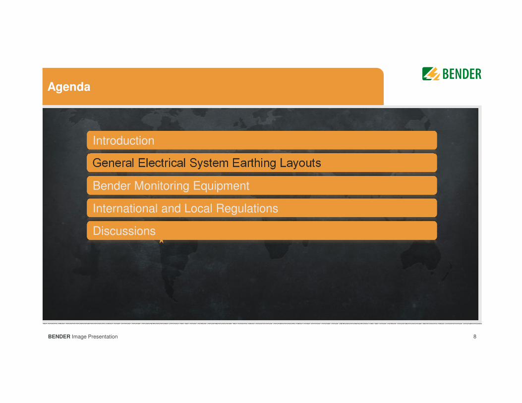
Agenda
General Electrical System Earthing LayoutsGeneral Electrical System Earthing Layouts
Bender Monitoring EquipmentBender Monitoring Equipment
International and Local RegulationsInternational and Local Regulations
DiscussionsDiscussions
IntroductionIntroduction
4BENDER Image Presentation
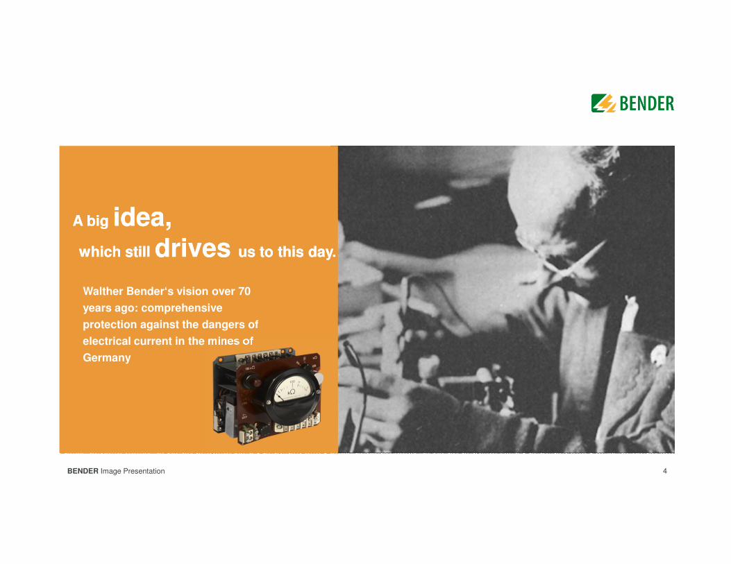
A big idea, which still drives us to this day.
A big idea, which still drives us to this day.
Walther Bender‘s vision over 70
years ago: comprehensive
protection against the dangers of
electrical current in the mines of
Germany
5BENDER Image Presentation
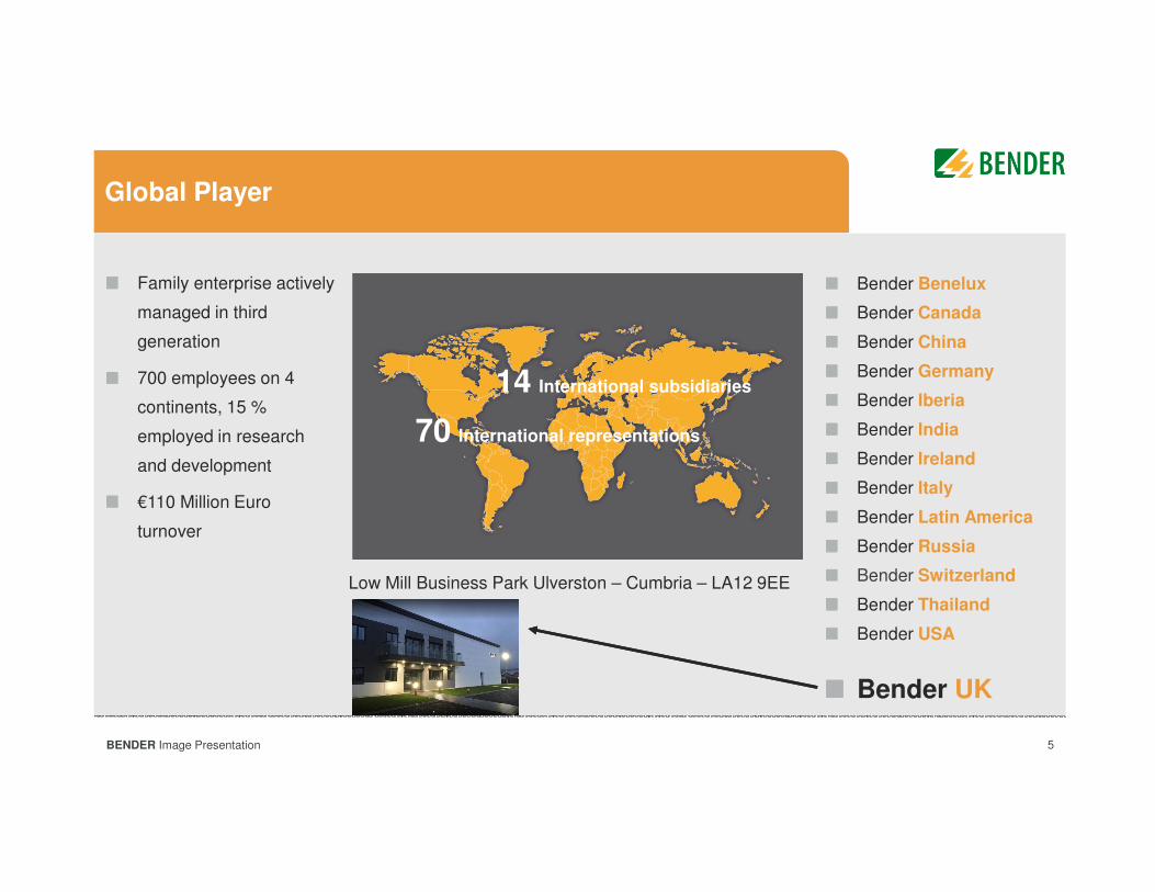
Global Player
Family enterprise actively
managed in third
generation
700 employees on 4
continents, 15 %
employed in research
and development
€110 Million Euro
turnover
14 International subsidiaries
70 International representations
Bender Benelux
Bender Canada
Bender China
Bender Germany
Bender Iberia
Bender India
Bender Ireland
Bender Italy
Bender Latin America
Bender Russia
Bender Switzerland
Bender Thailand
Bender USA
Bender UK
Low Mill Business Park Ulverston – Cumbria – LA12 9EE
6BENDER > Image Presentation
Innovative Solutions
that identify risksbefore they occur.
Innovative Solutions
that identify risksbefore they occur.
We develop solutions for the electrical safety in a great variety of complex
applications.
Our trendsetting products protect men and machines and avoid downtimes.
Bender PhilosophyBender Philosophy
7BENDER Image Presentation
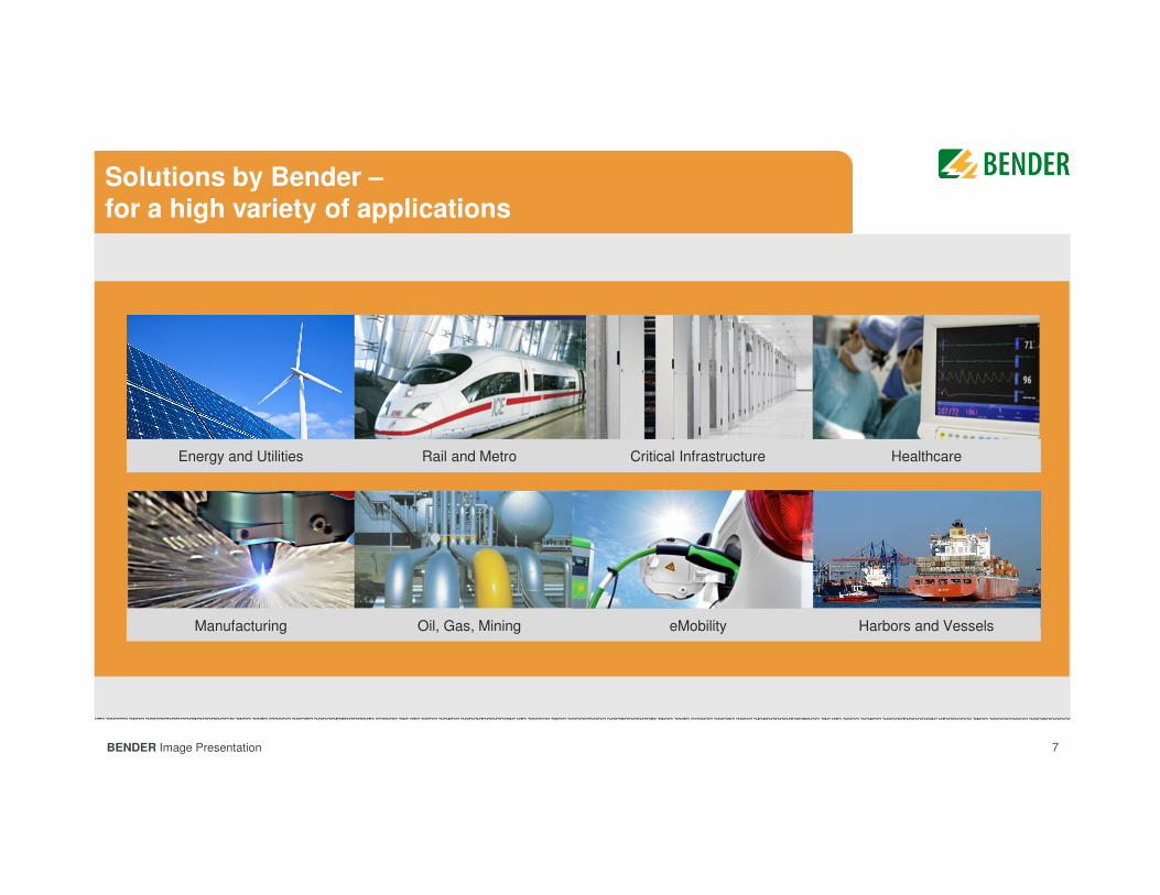
Solutions by Bender –for a high variety of applications
Energy and Utilities Rail and Metro Critical Infrastructure Healthcare
Manufacturing Oil, Gas, Mining eMobility Harbors and Vessels
8BENDER Image Presentation
Agenda
General Electrical System Earthing LayoutsGeneral Electrical System Earthing Layouts
Bender Monitoring EquipmentBender Monitoring Equipment
International and Local RegulationsInternational and Local Regulations
DiscussionsDiscussions
IntroductionIntroduction
9BENDER Image Presentation
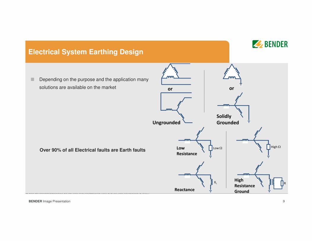
Depending on the purpose and the application many
solutions are available on the market
Electrical System Earthing Design
Over 90% of all Electrical faults are Earth faults
10BENDER Image Presentation
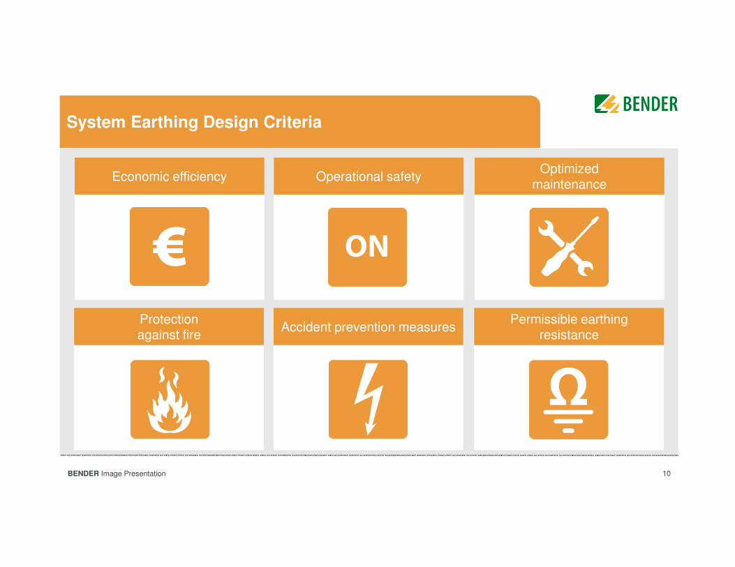
System Earthing Design Criteria
Höherer ErdungswiderstandHöhere UnfallsicherheitHöhere Brandsicherheit
Optimierte InstandhaltungHöhere BetriebssicherheitHöhere Wirtschaftlichkeit
Permissible earthing resistance
Accident prevention measuresProtection against fire
Optimized maintenance
Operational safetyEconomic efficiency
11BENDER Image Presentation 11
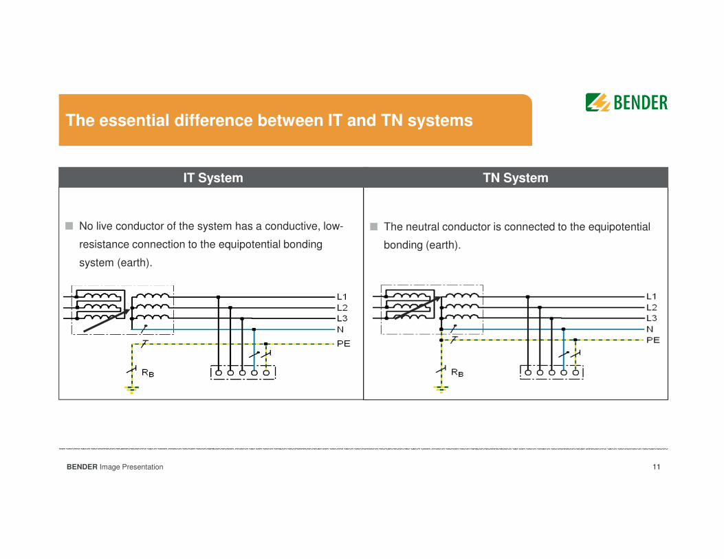
The neutral conductor is connected to the equipotential
bonding (earth).
No live conductor of the system has a conductive, low-
resistance connection to the equipotential bonding
system (earth).
The essential difference between IT and TN systems
IT System TN System
12BENDER Image Presentation 12
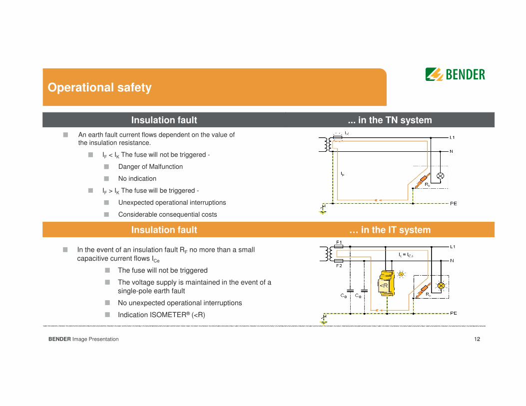
Operational safety
In the event of an insulation fault RF no more than a small
capacitive current flows ICe
The fuse will not be triggered
The voltage supply is maintained in the event of a
single-pole earth fault
No unexpected operational interruptions
Indication ISOMETER® (<R)
Insulation fault
An earth fault current flows dependent on the value of
the insulation resistance.
IF < IK The fuse will not be triggered -
Danger of Malfunction
No indication
IF > IK The fuse will be triggered -
Unexpected operational interruptions
Considerable consequential costs
... in the TN system
Insulation fault … in the IT system
13BENDER Image Presentation 13
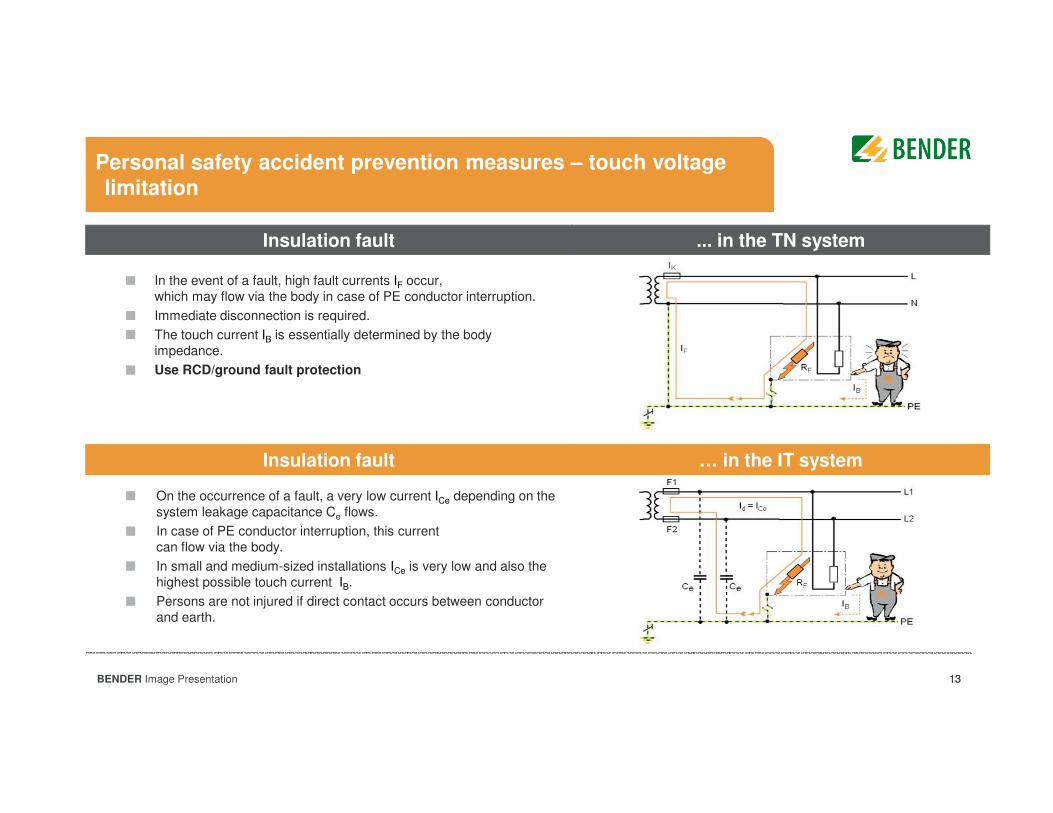
Personal safety accident prevention measures – touch voltage limitation
On the occurrence of a fault, a very low current ICe depending on the
system leakage capacitance Ce flows.
In case of PE conductor interruption, this current
can flow via the body.
In small and medium-sized installations ICe is very low and also the
highest possible touch current IB.
Persons are not injured if direct contact occurs between conductor
and earth.
In the event of a fault, high fault currents IF occur,
which may flow via the body in case of PE conductor interruption.
Immediate disconnection is required.
The touch current IB is essentially determined by the body
impedance.
Use RCD/ground fault protection
Insulation fault ... in the TN system
Insulation fault … in the IT system
14BENDER Image Presentation 14
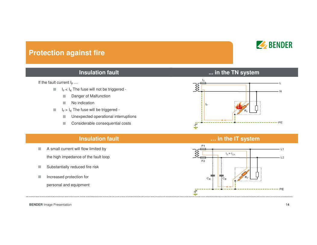
Protection against fire
A small current will flow limited by
the high impedance of the fault loop
Substantially reduced fire risk
Increased protection for
personal and equipment
If the fault current IF …
IF < IK The fuse will not be triggered -
Danger of Malfunction
No indication
IF > IK The fuse will be triggered -
Unexpected operational interruptions
Considerable consequential costs
Insulation fault ... in the TN system
Insulation fault … in the IT system
15BENDER Image Presentation 15
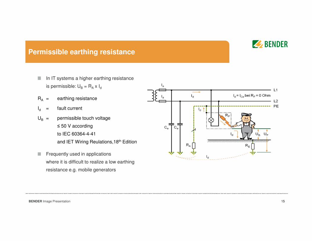
Permissible earthing resistance
In IT systems a higher earthing resistance
is permissible: UB = RA x Id
RA = earthing resistance
Id = fault current
UB = permissible touch voltage
≤ 50 V according
to IEC 60364-4-41
and IET Wiring Reulations,18th Edition
Frequently used in applications
where it is difficult to realize a low earthing
resistance e.g. mobile generators
16BENDER Image Presentation
Resistance grounded system
NG
R
XC0
3IC0
GroundFault
IG
3IC0IR
IR
� ����
3��
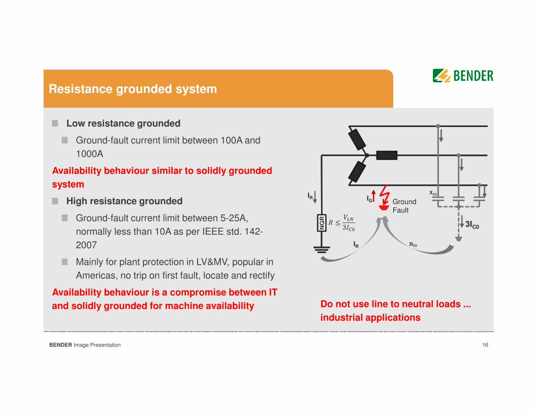
Low resistance grounded
Ground-fault current limit between 100A and
1000A
Availability behaviour similar to solidly grounded
system
High resistance grounded
Ground-fault current limit between 5-25A,
normally less than 10A as per IEEE std. 142-
2007
Mainly for plant protection in LV&MV, popular in
Americas, no trip on first fault, locate and rectify
Availability behaviour is a compromise between IT
and solidly grounded for machine availability Do not use line to neutral loads ...
industrial applications
17BENDER Image Presentation
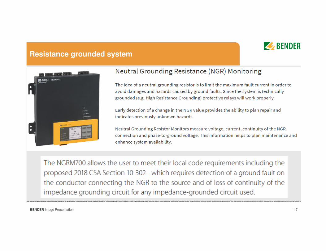
Resistance grounded system
18BENDER Image Presentation 18
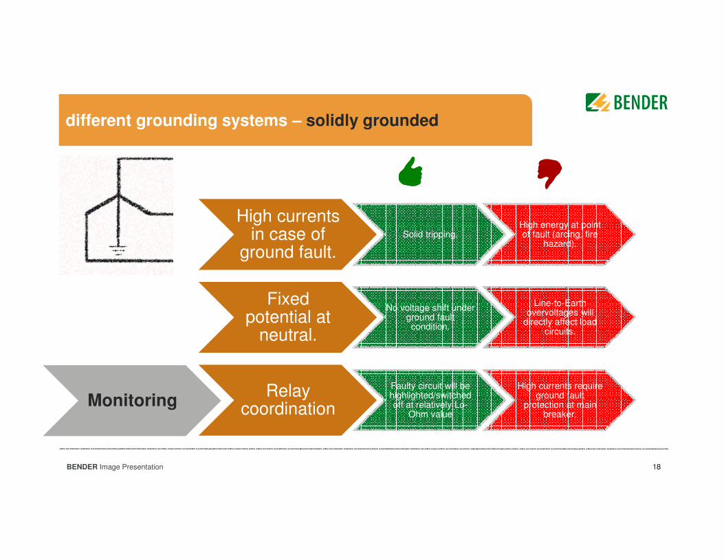
different grounding systems – solidly grounded
High currents in case of
ground fault.Solid tripping.
High energy at point of fault (arcing, fire
hazard).
Fixed potential at
neutral.
No voltage shift under ground fault condition.
Line-to-Earth overvoltages will
directly affect load circuits.
Relay coordination
Faulty circuit will be highlighted/switched off at relatively Lo-
Ohm value
High currents require ground fault
protection at main breaker.
Monitoring
19BENDER Image Presentation 19
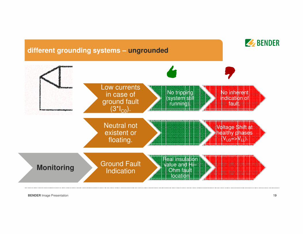
different grounding systems – ungrounded
Low currents in case of
ground fault (3*IC0).
No tripping (system still
running).
No inherent indication of
fault.
Neutral not existent or
floating.
Voltage Shift at healthy phases
(VLG=>VLL).
Ground Fault Indication
Real insulation value and Hi–
Ohm fault location
Monitoring
20BENDER Image Presentation 20
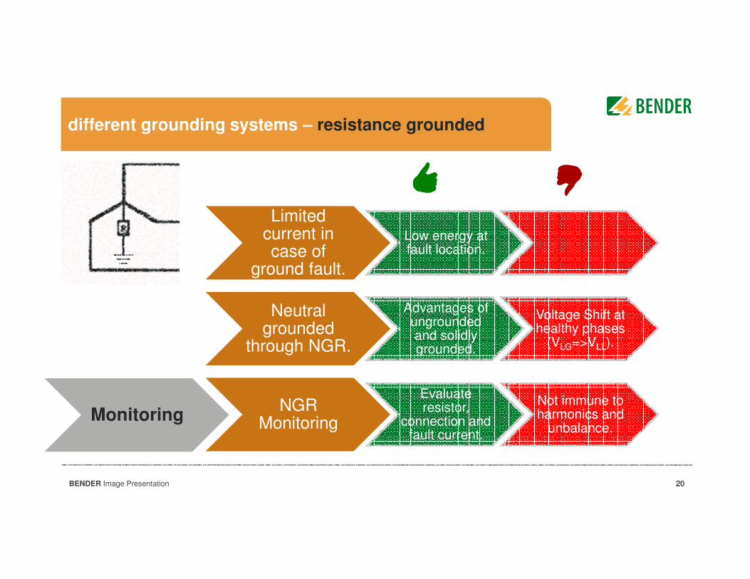
different grounding systems – resistance grounded
Limited current in case of
ground fault.
Low energy at fault location.
Neutral grounded
through NGR.
Advantages of ungrounded and solidly grounded.
Voltage Shift at healthy phases
(VLG=>VLL).
NGR Monitoring
Evaluate resistor,
connection and fault current.
Not immune to harmonics and
unbalance.Monitoring
21BENDER Image Presentation
Agenda
General Electrical System Earthing LayoutsGeneral Electrical System Earthing Layouts
Bender Monitoring EquipmentBender Monitoring Equipment
International and Local RegulationsInternational and Local Regulations
DiscussionsDiscussions
IntroductionIntroduction
22BENDER Image Presentation
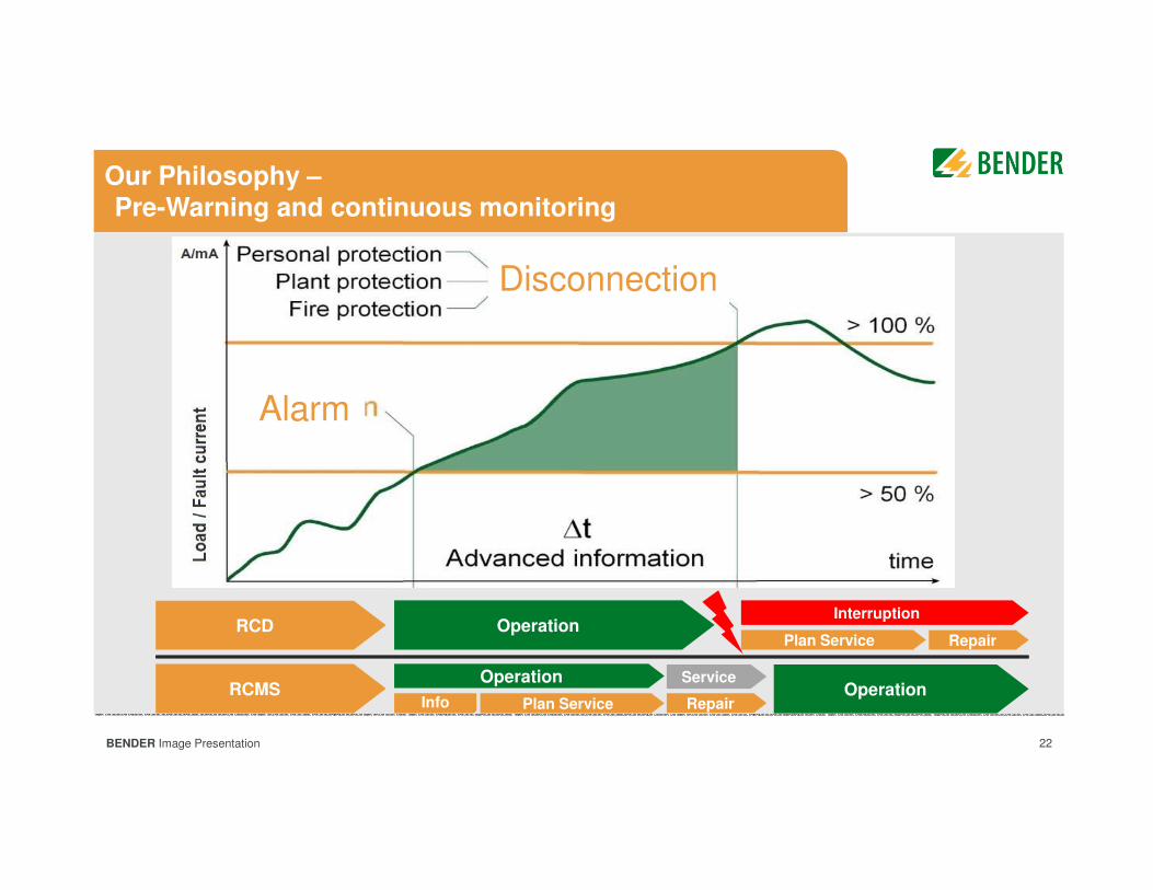
Our Philosophy –Pre-Warning and continuous monitoring
RCD
RCMS
Operation
Operation
Interruption
RepairPlan ServiceInfoOperation
Plan Service
Service
Repair
Disconnection
Alarm
23BENDER Image Presentation
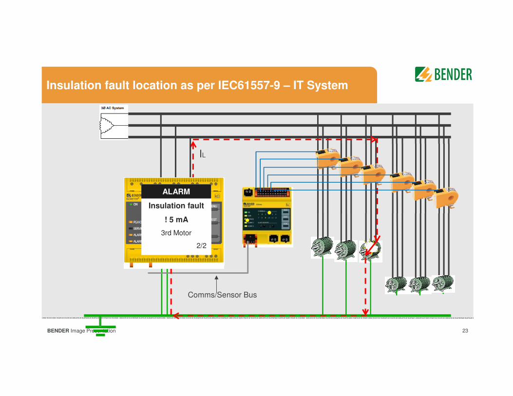
Insulation fault location as per IEC61557-9 – IT System
IL
Comms/Sensor Bus
ALARM
Insulation fault
! 5 mA
BS Bus 2 Chan 3
2/2
ALARMALARM
Insulation fault
! 5 mA
3rd Motor
2/2
ALARM

24BENDER Image Presentation 24
Residual current monitoring for TN system – BS EN 62020/ BS EN 50628:2016
Sensitive monitoring e.g. from 1mA for
developing insulation faults
Pre-warn against electric shock and
potential fire hazard
AC + DC sensitive
Continuous monitoring of cables and
connected loads
No requirement to disconnect for
periodic Insulation resistance testing
Comms
25BENDER Image Presentation
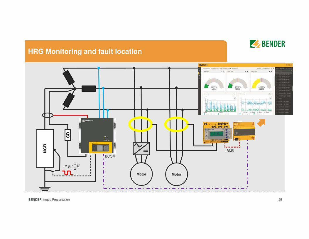
HRG Monitoring and fault location
Motor Motor
CD
NG
R
BCOM
BMS
e.g.:
��
26BENDER Image Presentation 26
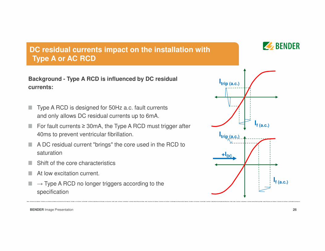
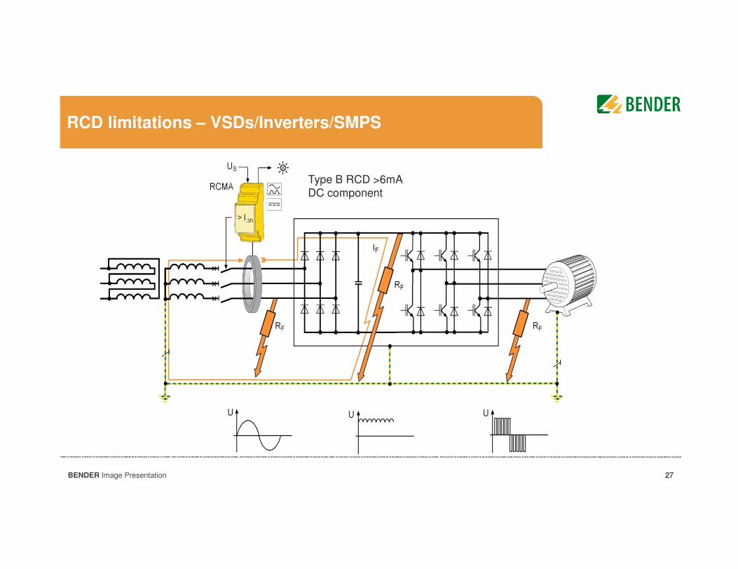
DC residual currents impact on the installation with Type A or AC RCD
Background - Type A RCD is influenced by DC residual
currents:
Type A RCD is designed for 50Hz a.c. fault currents
and only allows DC residual currents up to 6mA.
For fault currents ≥ 30mA, the Type A RCD must trigger after
40ms to prevent ventricular fibrillation.
A DC residual current "brings" the core used in the RCD to
saturation
Shift of the core characteristics
At low excitation current.
→ Type A RCD no longer triggers according to the
specification
+IDC
If (a.c.)
Itrip (a.c.)
If (a.c.)
Itrip (a.c.)
27BENDER Image Presentation 27
RCD limitations – VSDs/Inverters/SMPS
Type B RCD >6mA DC component
28BENDER Image Presentation
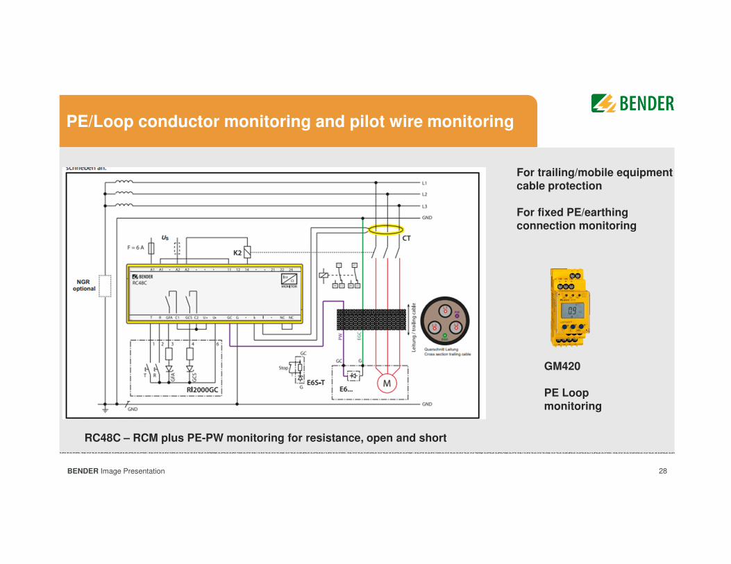
PE/Loop conductor monitoring and pilot wire monitoring
GM420
PE Loop monitoring
RC48C – RCM plus PE-PW monitoring for resistance, open and short
For trailing/mobile equipment cable protection
For fixed PE/earthing connection monitoring
29BENDER Image Presentation
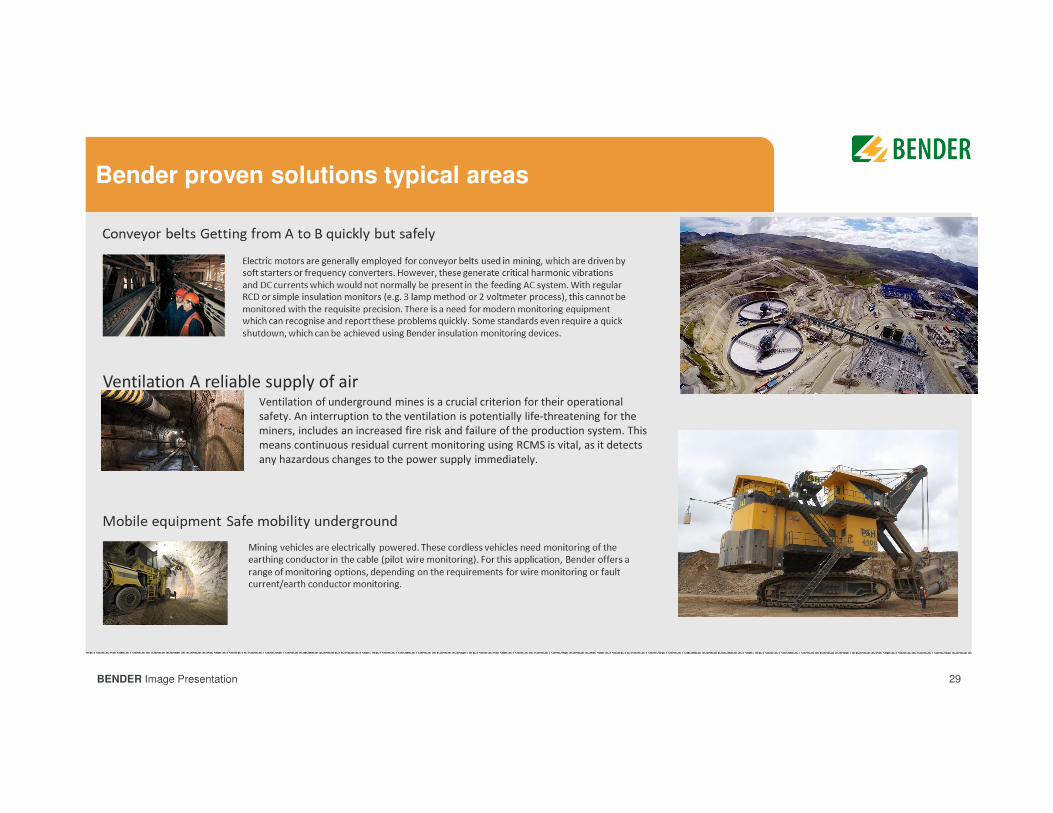
Bender proven solutions typical areas
Ventilation of underground mines is a crucial criterion for their operational
safety. An interruption to the ventilation is potentially life-threatening for the
miners, includes an increased fire risk and failure of the production system. This
means continuous residual current monitoring using RCMS is vital, as it detects
any hazardous changes to the power supply immediately.
Ventilation A reliable supply of air
30BENDER Image Presentation
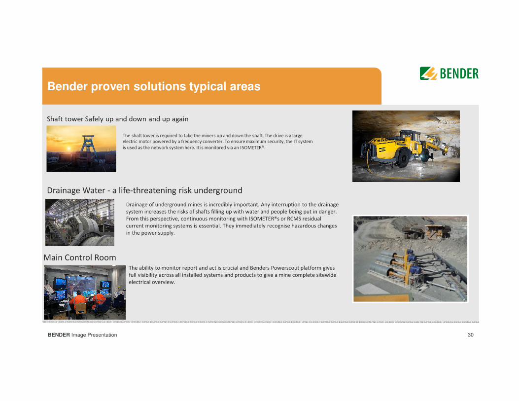
Bender proven solutions typical areas
Drainage of underground mines is incredibly important. Any interruption to the drainage
system increases the risks of shafts filling up with water and people being put in danger.
From this perspective, continuous monitoring with ISOMETER®s or RCMS residual
current monitoring systems is essential. They immediately recognise hazardous changes
in the power supply.
Drainage Water - a life-threatening risk underground
Main Control RoomThe ability to monitor report and act is crucial and Benders Powerscout platform gives
full visibility across all installed systems and products to give a mine complete sitewide
electrical overview.

31BENDER Image Presentation
Agenda
General Electrical System Earthing LayoutsGeneral Electrical System Earthing Layouts
Bender Monitoring EquipmentBender Monitoring Equipment
International and Local RegulationsInternational and Local Regulations
DiscussionsDiscussions
IntroductionIntroduction
32BENDER Image Presentation
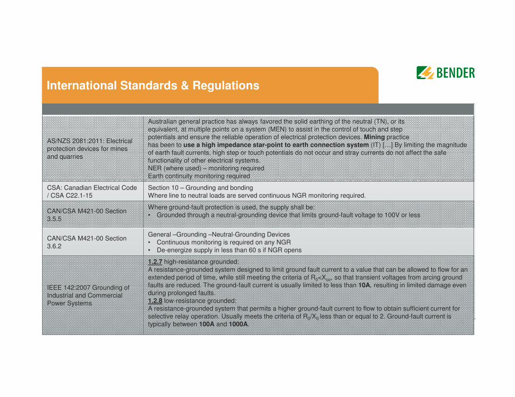
International Standards & Regulations
AS/NZS 2081:2011: Electrical
protection devices for mines
and quarries
Australian general practice has always favored the solid earthing of the neutral (TN), or its
equivalent, at multiple points on a system (MEN) to assist in the control of touch and step
potentials and ensure the reliable operation of electrical protection devices. Mining practice
has been to use a high impedance star-point to earth connection system (IT) […] By limiting the magnitude
of earth fault currents, high step or touch potentials do not occur and stray currents do not affect the safe
functionality of other electrical systems.
NER (where used) – monitoring required
Earth continuity monitoring required
CSA: Canadian Electrical Code
/ CSA C22.1-15
Section 10 – Grounding and bonding
Where line to neutral loads are served continuous NGR monitoring required.
CAN/CSA M421-00 Section
3.5.5
Where ground-fault protection is used, the supply shall be:
• Grounded through a neutral-grounding device that limits ground-fault voltage to 100V or less
CAN/CSA M421-00 Section
3.6.2
General –Grounding –Neutral-Grounding Devices
• Continuous monitoring is required on any NGR
• De-energize supply in less than 60 s if NGR opens
IEEE 142:2007 Grounding of
Industrial and Commercial
Power Systems
1.2.7 high-resistance grounded:
A resistance-grounded system designed to limit ground fault current to a value that can be allowed to flow for an
extended period of time, while still meeting the criteria of R0<Xco, so that transient voltages from arcing ground
faults are reduced. The ground-fault current is usually limited to less than 10A, resulting in limited damage even
during prolonged faults.
1.2.8 low-resistance grounded:
A resistance-grounded system that permits a higher ground-fault current to flow to obtain sufficient current for
selective relay operation. Usually meets the criteria of R0/X0 less than or equal to 2. Ground-fault current is
typically between 100A and 1000A.
33BENDER Image Presentation
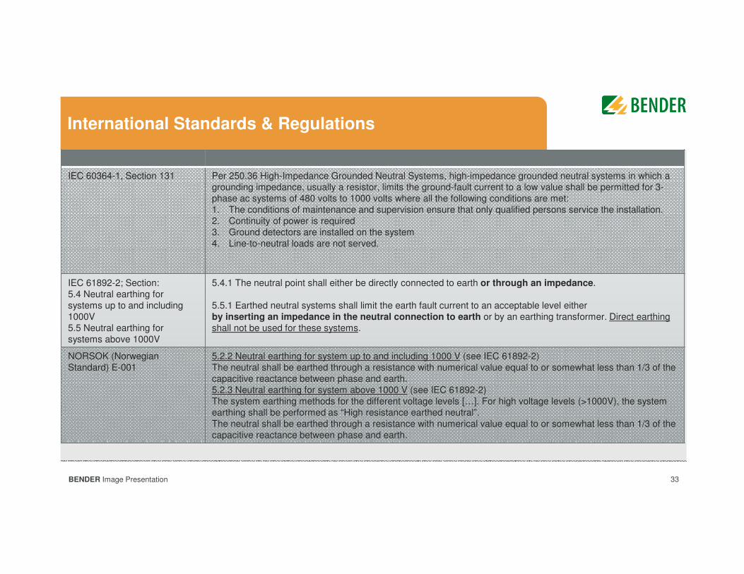
International Standards & Regulations
IEC 60364-1, Section 131 Per 250.36 High-Impedance Grounded Neutral Systems, high-impedance grounded neutral systems in which a
grounding impedance, usually a resistor, limits the ground-fault current to a low value shall be permitted for 3-
phase ac systems of 480 volts to 1000 volts where all the following conditions are met:
1. The conditions of maintenance and supervision ensure that only qualified persons service the installation.
2. Continuity of power is required
3. Ground detectors are installed on the system
4. Line-to-neutral loads are not served.
IEC 61892-2; Section:
5.4 Neutral earthing for
systems up to and including
1000V
5.5 Neutral earthing for
systems above 1000V
5.4.1 The neutral point shall either be directly connected to earth or through an impedance.
5.5.1 Earthed neutral systems shall limit the earth fault current to an acceptable level either
by inserting an impedance in the neutral connection to earth or by an earthing transformer. Direct earthing
shall not be used for these systems.
NORSOK (Norwegian
Standard) E-001
5.2.2 Neutral earthing for system up to and including 1000 V (see IEC 61892-2)
The neutral shall be earthed through a resistance with numerical value equal to or somewhat less than 1/3 of the
capacitive reactance between phase and earth.
5.2.3 Neutral earthing for system above 1000 V (see IEC 61892-2)
The system earthing methods for the different voltage levels […]. For high voltage levels (>1000V), the system
earthing shall be performed as “High resistance earthed neutral”.
The neutral shall be earthed through a resistance with numerical value equal to or somewhat less than 1/3 of the
capacitive reactance between phase and earth.
34BENDER Image Presentation
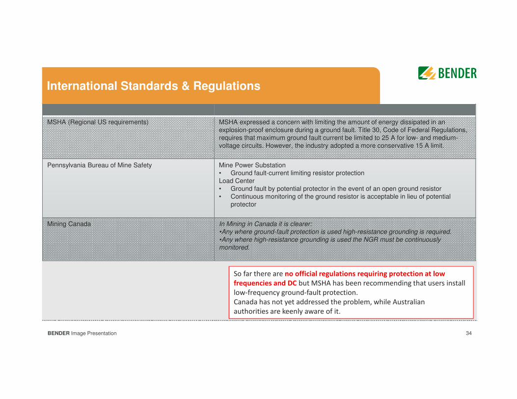
International Standards & Regulations
MSHA (Regional US requirements) MSHA expressed a concern with limiting the amount of energy dissipated in an
explosion-proof enclosure during a ground fault. Title 30, Code of Federal Regulations,
requires that maximum ground fault current be limited to 25 A for low- and medium-
voltage circuits. However, the industry adopted a more conservative 15 A limit.
Pennsylvania Bureau of Mine Safety Mine Power Substation
• Ground fault-current limiting resistor protection
Load Center
• Ground fault by potential protector in the event of an open ground resistor
• Continuous monitoring of the ground resistor is acceptable in lieu of potential
protector
Mining Canada In Mining in Canada it is clearer:
•Any where ground-fault protection is used high-resistance grounding is required.
•Any where high-resistance grounding is used the NGR must be continuously
monitored.
So far there are no official regulations requiring protection at low
frequencies and DC but MSHA has been recommending that users install
low-frequency ground-fault protection.
Canada has not yet addressed the problem, while Australian
authorities are keenly aware of it.
35BENDER Image Presentation 35
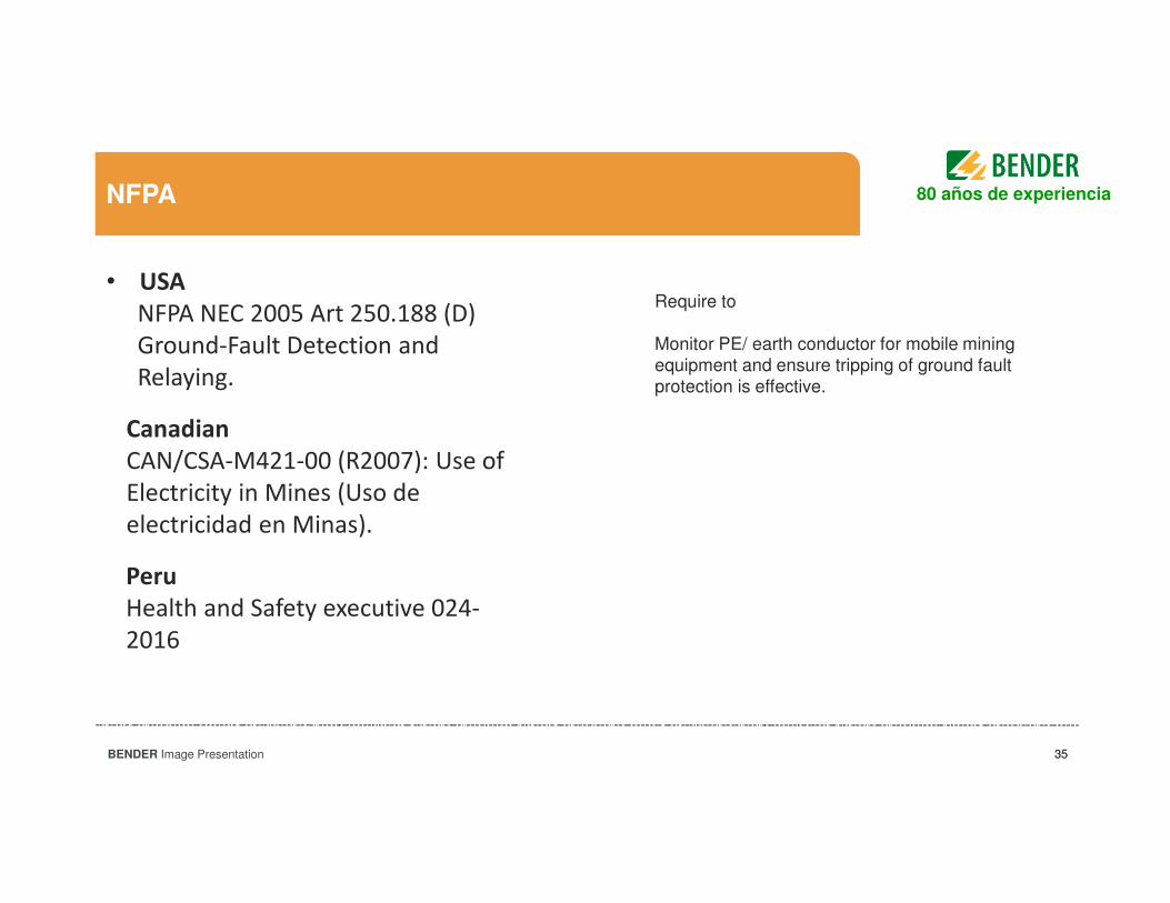
NFPA
• USA
NFPA NEC 2005 Art 250.188 (D)
Ground-Fault Detection and
Relaying.
Require to
Monitor PE/ earth conductor for mobile miningequipment and ensure tripping of ground faultprotection is effective.
80 años de experiencia
Canadian
CAN/CSA-M421-00 (R2007): Use of
Electricity in Mines (Uso de
electricidad en Minas).
Peru
Health and Safety executive 024-
2016
36BENDER Image Presentation
Agenda
General Electrical System Earthing LayoutsGeneral Electrical System Earthing Layouts
Bender Monitoring EquipmentBender Monitoring Equipment
International and Local RegulationsInternational and Local Regulations
DiscussionsDiscussions
IntroductionIntroduction
37BENDER Image Presentation 37
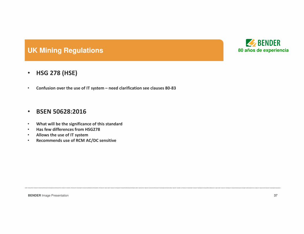
UK Mining Regulations
• HSG 278 (HSE)
• Confusion over the use of IT system – need clarification see clauses 80-83
• BSEN 50628:2016
• What will be the significance of this standard
• Has few differences from HSG278
• Allows the use of IT system
• Recommends use of RCM AC/DC sensitive
80 años de experiencia
38BENDER Image Presentation 38
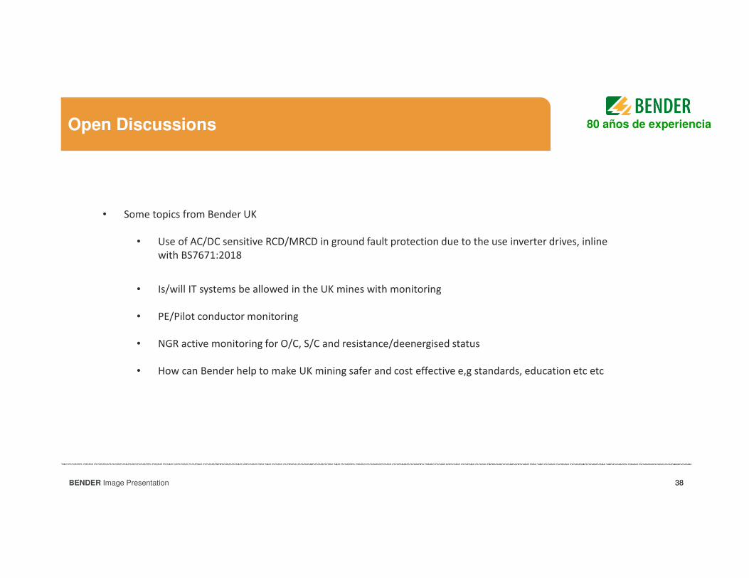
Open Discussions
• Some topics from Bender UK
• Use of AC/DC sensitive RCD/MRCD in ground fault protection due to the use inverter drives, inline
with BS7671:2018
• Is/will IT systems be allowed in the UK mines with monitoring
• PE/Pilot conductor monitoring
• NGR active monitoring for O/C, S/C and resistance/deenergised status
• How can Bender help to make UK mining safer and cost effective e,g standards, education etc etc
80 años de experiencia
39BENDER Image Presentation
Bender GmbH & Co. KG
www.bender.de
Pictures: Bender archive, www.pixelio.de, www.fotolia.de, www.istockphoto.com, Fraport AG
Subject to modification - © Bender GmbH & Co. KG, Germany
The presentation, its content, pictures and drawings are protected by copyright law. Duplication, translation, microfilming and transfer into any electronic systems, especially for commercial purposes is not allowed and subject to approval by the issuer. We do not assume any responsibility and liability for faulty or missing content. All data is based on manufacturers‘ information. All logos and product descriptions are registered trademarks of the respective manufacturer.