march, 2008 part #46687-00 - toshibadanger warning symbol is used to indicate situations, locations,...
TRANSCRIPT

March, 2008Part #46687-004


TOSHIBA
i
IMPORTANT NOTICE
The instructions contained in this manual are not intended to cover all of the detailsor variations in equipment, nor to provide for every possible contingencyto be met in connection with installation, operation, or maintenance. Shouldadditional information be desired or should particular problems arise which are notcovered sufficiently for the purchaser's purposes, the matter should be referred tothe local Toshiba sales office.
The contents of this instruction manual shall not become a part of or modify anyprior or existing agreement, commitment, or relationship. The sales contractcontains the entire obligation of Toshiba International Corporation's AdjustableSpeed Drive Division. The warranty contained in the contract between the partiesis the sole warranty of Toshiba International Corporation's Adjustable Speed DriveDivision and any statements contained herein do not create new warranties ormodify the existing warranty.
Toshiba International Corporation reserves the right, without prior notice, to updateinformation, make product changes, or to discontinue any product or serviceidentified in this publication.
Any electrical or mechanical modification to this equipment,without prior written consent of Toshiba InternationalCorporation, will void all warranties and may void UL listing.
AC ADJUSTABLE SPEED DRIVE
Please complete the Extended Warranty Card supplied with this inverter and returnit by prepaid mail to Toshiba. This activates the extended warranty. If additionalinformation or technical assistance is required, call Toshiba's marketing departmenttoll free at (800) 231-1412 or write to: Toshiba International Corporation, 13131 W.Little York Road, Houston, TX 77041-9990.
For your records, complete the following information about the drive with which thismanual was shipped.
H3 Model Number:
H3 Serial Number:
Date of Installation:
Inspected By:
Name of Application:
TOSHIBA
ii
INTRODUCTION
Thank you for purchasing the H3 adjustable speed drive. This adjustable frequency solid-state AC drivefeatures "True Torque Control" - Toshiba's 'vector algorithm' that enables motors to develop high startingtorque and compensates for motor slip. The H3 also features a multi-lingual forty-character LCD display,RS232 port, dynamic braking transistor and ground fault, overload, and overcurent protection. These fea-tures, combined with built-in special control features such as PID, drooping, trim, and dancer control, makethe H3 suitable for a wide variety of applications that require unparalleled motor control andreliability.
It is the intent of this operation manual to provide a guide for safely installing, operating, and maintaining thedrive. This operation manual contains a section of general safety instructions and is markedthroughout with warning symbols. Read this operation manual thoroughly before installing and operatingthis electrical equipment.
All safety warnings must be followed to ensure personal safety.
Follow all precautions to attain proper equipment performance and longevity.
We hope that you find this operation manual informative and easy to use. For assistance with your H3, forinformation on our free drive application school, or for information on Toshiba's complete line of motors,adjustable speed drives, switchgear, instrumentation, uninterruptable power supplies, PLCs, andmotor control products, please call toll free (800) 231-1412 or write to our plant at: Toshiba InternationalCorporation, 13131 W. Little York Road, Houston, TX 77041-9990.
Again, thank you for your purchase of this product.
COPYRIGHT © [MARCH, 2008] TOSHIBA INTERNATIONAL CORPORATION

TOSHIBA
iii
GENERAL SAFETY INSTRUCTIONS
Warnings in this manual appear in either of two ways:
1) Danger warnings - The danger warning symbol is an exclamation mark enclosed in atriangle which precedes the 3/16" high letters spelling the word "DANGER". TheDanger warning symbol is used to indicate situations, locations, and conditions thatcan cause serious injury or death:
2) Caution warnings - The caution warning symbol is an exclamation mark enclosed in atriangle which precedes the 3/16" high letters spelling the word "CAUTION". TheCaution warning symbol is used to indicate situations and conditions that can causeoperator injury and/or equipment damage:
Other warning symbols may appear along with the Danger and Caution symbol and are used to specifyspecial hazards. These warnings describe particular areas where special care and/or procedures arerequired in order to prevent serious injury and possible death:
1) Electrical warnings - The electrical warning symbol is a lighting bolt mark enclosed ina triangle. The Electrical warning symbol is used to indicate high voltage locations andconditions that may cause serious injury or death if the proper precautions are notobserved:
DANGER
CAUTION
2) Explosion warnings - The explosion warning symbol is an explosion mark enclosed ina triangle. The Explosion warning symbol is used to indicate locations and conditionswhere molten, exploding parts may cause serious injury or death if the properprecautions are not observed:
For the purpose of this manual and product labels, a Qualified Person is one who is familiar with theinstallation, construction, operation and maintenance of the equipment and the hazards involved.This person must:
1) Carefully read the entire operation manual.
2) Be trained and authorized to safely energize, de-energize, clear faults, ground, lockoutand tag circuits and equipment in accordance with established safety practices.
3) Be trained in the proper care and use of protective equipment such as safety shoes,rubber gloves, hard hats, safety glasses, face shields, flash clothing, etc. inaccordance with established safety practices.
4) Be trained in rendering first aid.

TOSHIBA
iv
CONTENTS
PAGE
Disclaimer ............................................................................................... i
Introduction .............................................................................................. ii
General Safety Instructions ..................................................................... iii
Contents ............................................................................................ iv-vi
Section 1 Inspection/Storage/DisposalInspection of the New Unit .........................................................................1-1Storage .............................................................................................1-1Disposal .............................................................................................1-1
Section 2 Installation and OperationInstallation Safety Precautions ..................................................................2-1Operating Safety Precautions....................................................................2-2Confirmation of Wiring ...............................................................................2-3Start-up and Test .......................................................................................2-4Maintenance .............................................................................................2-4
Section 3 Specifications230 Volt NEMA Type 1 Chassis Ratings ...................................................3-1460 Volt NEMA Type 1 Chassis Ratings ...................................................3-1Standard Specifications .............................................................................3-2
Section 4 WiringStandard Connection Diagrams ................................................................4-1Selection of Main Circuit Wiring Equipment andStandard Cable Sizes ................................................................................4-3Grounding .............................................................................................4-5Application Notes: Motor Selection............................................................4-5Connection Examples
Potentiometer Operation.................................................................4-64-20 mA Reference Operation ........................................................4-7Keypad Reference and Remote Stop/Start ....................................4-8RS232 Port .....................................................................................4-90-10 Volt Reference Operation .......................................................4-9

TOSHIBA
v
CONTENTS (cont'd)
PAGE
Section 5 Jumper and Terminal ConnectionsTerminal Strip Board..................................................................................5-1Control Board ............................................................................................5-2Terminal Connections and Functions ........................................................5-3
Section 6 Operating PanelPanel Layout .............................................................................................6-1Keys and Functions ...................................................................................6-2
Section 7 Keypad FunctionsLocal Mode .............................................................................................7-1
Forward/Rerverse Change .............................................................7-1Jog .............................................................................................7-1Coast Stop ......................................................................................7-2
Programming Mode ...................................................................................7-2Remote Mode ............................................................................................7-2
ESTOP............................................................................................7-2Other: Language Selection ........................................................................7-2Monitor Mode.............................................................................................7-3
Monitoring "RR" Input Special Function ..........................................7-4Monitoring Pattern Run ...................................................................7-4
Section 8 Programming ChartsFundamental Parameters #1 .....................................................................8-1Fundamental Parameters #2 .....................................................................8-2Panel Control Parameters .........................................................................8-3Special Control Parameters.......................................................................8-4Terminal Selection Parameters .................................................................8-5Frequency Setting Parameters ..................................................................8-8Protection Parameters ..............................................................................8-13Pattern Run Control Parameters ..............................................................8-16Feedback Parameters ..............................................................................8-22Communication Setting Parameters .........................................................8-24Industrial Application Parameters (Pump) ................................................8-26Industrial Application Parameters (Fan) ...................................................8-26Industrial Application Parameters (Conveyor) ..........................................8-26Industrial Application Parameters (Hoist) .................................................8-26Industrial Application Parameters (Textiles) .............................................8-26

TOSHIBA
vi
CONTENTS (cont'd)PAGE
Section 8 Programming Charts (cont'd)Industrial Application Parameters (Machine Tools) ..................................8-26AM/FM Terminal Adjustment Parameters.................................................8-27Utility Parameters .....................................................................................8-28Motor Parameters .....................................................................................8-32Parameter Tree ........................................................................................8-33
Section 9 ProgrammingGroups .............................................................................................9-1Blinding .............................................................................................9-2Search Function ........................................................................................9-2Parameter Explanations ............................................................................9-3Programming Examples ...........................................................................9-30
Section 10 ServiceRequesting After Sales Service ................................................................10-1Parts Service Life .....................................................................................10-2Troubleshooting ........................................................................................10-3
How to Clear a Fault ......................................................................10-3Drive Fault Displays and Explanations ..........................................10-3Drive Warning Displays and Explanations .....................................10-7
Section 11 Dimensions/WeightsBasic Dimensions .....................................................................................11-1Shipping Weights......................................................................................11-3Drive Options ............................................................................................11-4Keypad Cutout ..........................................................................................11-5
Section 12 Index ............................................................................................12-1
TOSHIBA
1 - 1
SECTION 1: Inspection/Storage/Disposal
Inspection of the New UnitUpon receipt of the H3, a careful inspection for shipping damage should be made. After uncrating:1) Check the unit for loose, broken, bent or otherwise damaged parts due to
shipping.
2) Check to see that the rated capacity and the model number specified on thenameplate conform to the order specifications.
Storage1) Store in a well ventilated location and preferably in the original carton if the
inverter will not be used immediately after purchase.
2) Avoid storage in locations with extreme temperatures, high humidity, dust, ormetal particles.
DisposalPlease contact your state environmental agency for details on disposal of electrical componentsand packaging in your particular area. Never dispose of electrical components viaincineration.
Spec
ifica
tions
Insp
ectio
nPr
ecau
tions
Wiri
ngJu
mpe
rsPa
nel
Keyp
adPa
ram
eter
sPr
ogra
mm
ing
Serv
ice
Dim
ensi
ons
Inde
x

TOSHIBA
2 - 1
SECTION 2: Installation and Operation
Installation Safety Precautions
1) Install in a secure and upright position in a well ventilated location that is out ofdirect sunlight. The ambient temperature should be between -10° C and 40° C.
2) Allow a clearance space of 8 inches (20 cm) for the top and bottom and 2 inches(5 cm) on both sides. For models 2010-2270 and models 4015-4500, the top and bottomclearance can be reduced to 4 inches (10 cm). This space will insure adequate ventilation.Do not obstruct any of the ventilation openings.
3) Avoid installation in areas where vibration, heat, humidity, dust, steel particles,or sources of electrical noise are present.
4) Adequate working space should be provided for adjustment, inspection andmaintenance.
5) Adequate lighting should be available for troubleshooting and maintenance.
6) A noncombustible insulating floor or mat should be provided in the areaimmediately surrounding the electrical system where maintenance is required.
7) Always ground the unit to prevent electrical shock and to helpreduce electrical noise. A separate ground cable should be runinside the conduit with the input, output, and control powercables (See Grounding page 4-5).
THE METAL OF CONDUIT IS NOT AN ACCEPTABLE GROUND.
8) Use lockout/tagout procedures before connecting three phase power of thecorrect voltage to input terminals L1, L2, L3 (R, S, T) and connect three phasepower from output terminals T1, T2, T3 (U, V, W) to a motor of the correct voltageand type for the application. Size the conductors in accordance with Selection ofMain Circuit Wiring Equipment and Standard Cable Sizes Page 4-3.
9) If conductors of a smaller than recommended size are used in parallel to sharecurrent then the conductors should be kept together in sets i.e. U1, V1, W1 inone conduit and U2, V2, W2 in another. National and local electrical codesshould be checked for possible cable derating factors if more than three powerconductors are run in the same conduit.
10) Install a molded case circuit breaker (MCCB) between the power source and theinverter. Size the MCCB to clear the available fault current of the power source.
11) Use separate metal conduits for routing the input power, output power, andcontrol circuits.
12) Installation of drive systems should conform to the National Electrical Code,regulations of the Occupational Safety and Health Administration, all national,regional or industry codes and standards.
13) If the factory provided enclosure is removed from the drive, then it must beprovided with an alternate enclosure before operating. The alternate enclosureshould be a minimum of NEMA 1.
CAUTION

TOSHIBA
2 - 2
Installation Safety Precautions (cont'd)
14) Do not connect control circuit terminal block return connections marked CC toinverter earth ground terminals marked GND(E). See Standard ConnectionDiagrams page 4-1 and Terminal Connections and Functions page 5-3.
15) If a secondary Magnetic Contactor (MC) is used between the inverter outputand the load, it should be interlocked so the ST-CC terminals are disconnectedbefore the output contactor is opened. If the output contactor is used for bypassoperation, it must also be interlocked so that commercial power is never appliedto the inverter output terminals (U,V,W).
16) Power factor improvement capacitors or surge absorbers must not be installedon the inverter's output.
17) Only qualified personnel should install this equipment.
Operating Safety Precautions
1) Do not power up the inverter until this entire operation manual is reviewed.
2) The input voltage must be within +/-10% of the specified input voltage. Voltagesoutside of this permissible tolerance range may cause internal protectiondevices to turn on or can cause damage to the unit. Also, the input frequencyshould be within +/-2 Hz of the specified input frequency.
3) Do not use this inverter with a motor whose rated input is greater than the ratedinverter output.
4) This inverter is designed to operate NEMA B motors. Consult the factory beforeusing the inverter for special applications such as an explosion proof motor orone with a repetitive type piston load.
5)
Do not touch any internal part with power applied to the inverter; first removethe power supply from the drive and wait until charge LED (see page 5-1 for location)is no longer illuminated. Charged capacitors can present a hazard even if sourcepower is removed. not touc h any internal part with
power applied to the inverter. First removethe sou 6) DO NOT OPERATE THIS UNIT WITH ITS CABINET DOOR OPEN.
7) Do not apply commercial power to the output terminals T1 (U), T2 (V), or T3(W) even if the inverter source power is off. Disconnect the inverter from themotor before megging or applying bypass voltage to the motor.
DANGER
CAUTION
CAUTION
Spec
ifica
tions
Prec
autio
nsW
iring
Jum
pers
Pane
lKe
ypad
Para
met
ers
Prog
ram
min
gSe
rvic
eD
imen
sion
sIn
dex
Insp
ectio
n
TOSHIBA
2 - 3
Operating Safety Precautions (cont'd)
8) Interface problems can occur when this drive is used in conjunction withsome types of process controllers. Signal isolation may be required toprevent controller and/or drive malfunction (contact Toshiba or the processcontroller manufacturer for additional information about compatibility andsignal isolation).
9) Do not open and then re-close a secondary magnetic contactor (MC) betweenthe drive and the load unless the drive is OFF (output frequency hasdropped to zero) and the motor is not rotating. Abrupt re-application of theload while drive is on or while motor is rotating can cause drive damage.
10) Use caution when setting output frequency. Overspeeding a motor can decrease itstorque-developing ability and can result in damage to the motor and/or drivenequipment.
11) Use caution when setting the acceleration and deceleration time. Unnecessarilyshort times can cause tripping of the drive and mechanical stress to loads.
12) Only qualified personnel should have access to the adjustments andoperation of this equipment. They should be familiar with the drive operatinginstructions and with the machinery being driven.
13) Only properly trained and qualified personnel should be allowed to servicethis equipment. See page iii.
14) Follow all warnings and precautions. Do not exceed equipment ratings.
Confirmation of Wiring
Make the following final checks before applying power to the unit:
1) Confirm that source power is connected to terminals L1, L2, L3 (R, S, T).Connection of incoming source power to any other terminals will damagethe drive.
2) The 3-phase source power should be within the correct voltage and frequencytolerances.
3) The motor leads must be connected to terminals T1, T2, T3 (U, V, W).
4) Make sure there are no short circuits or inadvertent grounds and tighten anyloose connector terminal screws.
CAUTION
CAUTION

TOSHIBA
2 - 4
Start-Up and Test
Prior to releasing an electrical drive system for regular operation after installation,the system should be given a start-up test by qualified personnel. This assurescorrect operation of the equipment for reasons of reliable and safe performance. It isimportant to make arrangements for such a check and that time is allowed for it.
When power is applied for the first time, the drive's parameters are set to the valueslisted as "FACTORY SETTING" in the charts starting on page 8-1. If these settings are notoptimal for the application, program the desired settings before initiating a run. Thedrive can be operated with no motor connected. Operation with no motorconnected or use with a small trial motor is recommended for initial adjustment or forlearning to adjust and operate the drive.
Maintenance
1) Use lockout/tagout procedures in accordance with local electrical codesbefore performing any drive maintenance.
2) Periodically check the operating drive for cleanliness.
3) Do not use liquid cleaning agents.
4) Keep the heatsink free of dust and debris.
5) Periodically check electrical connections for tightness (with power off,locked out, and with charge LED out (see page 5-1 for location) ).
CAUTION
CAUTION
Spec
ifica
tions
Prec
autio
nsW
iring
Jum
pers
Pane
lKe
ypad
Para
met
ers
Prog
ram
min
gSe
rvic
eD
imen
sion
sIn
dex
Insp
ectio
n
TOSHIBA
3 - 1
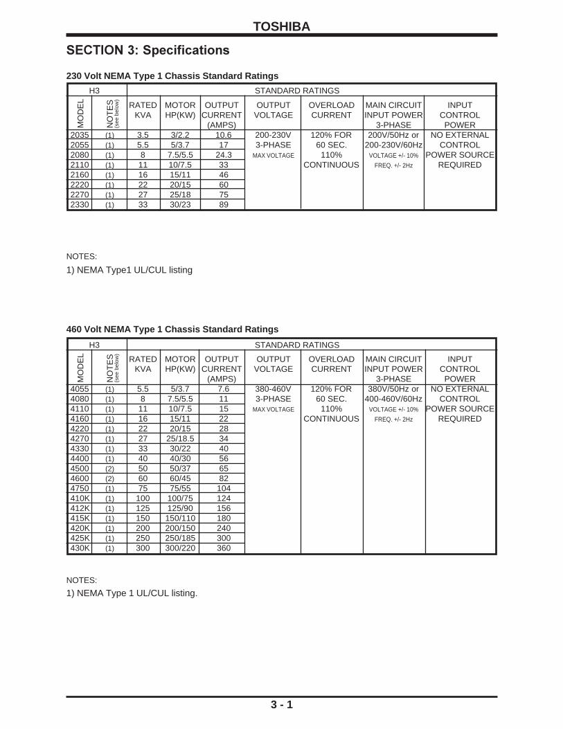
NOTES:
1) NEMA Type1 UL/CUL listing
H3 STANDARD RATINGS
RATED MOTOR OUTPUT OUTPUT OVERLOAD MAIN CIRCUIT INPUTKVA HP(KW) CURRENT VOLTAGE CURRENT INPUT POWER CONTROL
(AMPS) 3-PHASE POWER2035 (1) 3.5 3/2.2 10.6 200-230V 120% FOR 200V/50Hz or NO EXTERNAL2055 (1) 5.5 5/3.7 17 3-PHASE 60 SEC. 200-230V/60Hz CONTROL2080 (1) 8 7.5/5.5 24.3 MAX VOLTAGE 110% VOLTAGE +/- 10% POWER SOURCE2110 (1) 11 10/7.5 33 CONTINUOUS FREQ. +/- 2Hz REQUIRED2160 (1) 16 15/11 462220 (1) 22 20/15 602270 (1) 27 25/18 752330 (1) 33 30/23 89
SECTION 3: Specifications
MO
DE
L
NO
TE
S(s
ee b
elow
)
MO
DE
L
NO
TE
S
H3
(see
bel
ow)
STANDARD RATINGS
460 Volt NEMA Type 1 Chassis Standard Ratings
230 Volt NEMA Type 1 Chassis Standard Ratings
RATED MOTOR OUTPUT OUTPUT OVERLOAD MAIN CIRCUIT INPUTKVA HP(KW) CURRENT VOLTAGE CURRENT INPUT POWER CONTROL
(AMPS) 3-PHASE POWER4055 (1) 5.5 5/3.7 7.6 380-460V 120% FOR 380V/50Hz or NO EXTERNAL4080 (1) 8 7.5/5.5 11 3-PHASE 60 SEC. 400-460V/60Hz CONTROL4110 (1) 11 10/7.5 15 MAX VOLTAGE 110% VOLTAGE +/- 10% POWER SOURCE4160 (1) 16 15/11 22 CONTINUOUS FREQ. +/- 2Hz REQUIRED4220 (1) 22 20/15 284270 (1) 27 25/18.5 344330 (1) 33 30/22 404400 (1) 40 40/30 564500 (2) 50 50/37 654600 (2) 60 60/45 824750 (1) 75 75/55 104410K (1) 100 100/75 124412K (1) 125 125/90 156415K (1) 150 150/110 180420K (1) 200 200/150 240425K (1) 250 250/185 300430K (1) 300 300/220 360
NOTES:
1) NEMA Type 1 UL/CUL listing.

TOSHIBA
Principal Control System Sinusoidal PWM controlControl Output voltage regulation Same as power line.
Specifications Output frequency 0.01 to 400 Hz (0.1 to 80Hz default setting)*. 800 Hz operationpossible.
Frequency setting 0.1Hz from operating panel input (60Hz base), 0.01Hz from analoginput (60Hz base, 12-bit/0 to 10Vdc), 0.01Hz from computer interface(60Hz base)
Frequency accuracy Analog input: ±0.2% of the maximum output frequency (25°C±10°C),Digital input: ±0.01% (25°C±10°C)
Voltage/frequency Constant V/f, variable torque, automatic torque boost, True Torquecharacteristics Control and automatic energy-saving control/maximum voltage
frequency adjustment (25 to 400Hz), torque boost adjustment(0 to 30%), start-up frequency adjustment (0 to 10Hz).
PWM carrier frequency Adjustable between 0.5 and 10kHzTransistor type Insulated gate bipolar (IGBT)Output voltage regulation Drive can be programmed to fix max. output volts, let max. float with
input voltage, or set max. to input voltage sensed at power-up.Dynamic braking Feature not available in H3 drives above 30 HP.
Frequency Input signals 3k ohms potentiometer (1k ohm to 10k ohm-rated potentiometercan be connected). 0 to 10Vdc (Zin=33k ohm), ±10 Vdc (Zin=67kohm), +/-5 Vdc (Zin=34k ohm), 4 to 20mAdc (Zin=500 ohm)
Set point control (PID) Proportional gain, integral gain, anti-hunting gain, lag time constant,and PID error limit adjustments.
Operating Accel/decel time 0.1 to 6000 secs, accel/decel time 1 or 2 selection, accel/decelfunctions pattern selection
Forward or reverse run Forward run when F-CC closed (default); reverse run when R-CCclosed (default); reverse run when both closed (default); coast-stopwhen ST-CC opened (default); emergency coast stop by acommand from operating panel or terminal block; 3-wire control andmotorized speed pot programmable functions.
Jogging run Jog run from panel with JOG mode selection. Terminalblock operation possible with parameter settings.
Multispeed run Set frequency plus 15 preset speeds possible with combinations ofCC, SS1, SS2, SS3, and SS4 (default functions).
Retry When a protective function is activated, the system checks maincircuit devices, and attempts to restart. Settable to a maximumof 10 times; wait time adjustment (0 to 10 secs)
Soft stall Automatic load reduction during overload (Default setting: OFF).Automatic restart A coasting motor can be smoothly restarted (Default setting: OFF).Pattern Run 4 groups of 8 patterns each can be set to the 15 preset speed values.
A maximum of 32 different patterns can be run; terminal blockcontrol/repetitive run possible.
DC injection braking Braking starting frequency adjustment (0 to 120Hz), braking currentadjustment (0 to 100%), braking time adjustment (0 to 10secs),emergency stop braking function, motor shaft stationary control.
Upper/Lower limit Limits the frequency between the set values (0 to max. frequency).Can be indicated via output contact closure.
Frequency jump 3 jump frequency settings (each with unique band settings)Edit function Easy access user group containing all changed parametersBlind function Select to display needed parameter groups and parametersUser-defined defaults User's parameter values can be saved into a default library. User
can then default drive to Toshiba's values or to the user's own.
3 - 2
* Consult the factory for applications above 80 Hz.
ITEM STANDARD SPECIFICATIONS
Standard Specifications
Spec
ifica
tions
Prec
autio
nsW
iring
Jum
pers
Pane
lKe
ypad
Para
met
ers
Prog
ram
min
gSe
rvic
eD
imen
sion
sIn
dex
Insp
ectio
n

TOSHIBA
3 - 3
ITEM STANDARD SPECIFICATIONS
Standard Specifications (cont'd)
2
Display Interface 2-line backlit display LCD 20 characters per lineFault display Overcurrent, overvoltage, heatsink overheat, load-side short-circuit,
load-side ground fault, inverter overload, stator overcurrent duringstart-up, load-side overcurrent during start-up, EEPROM error, RAMerror, ROM error, communication error, (dynamic braking unitovercurrent/overload), (emergency stop), (undervoltage), (lowcurrent), (overtorque), (open output phase), (motor overload). Itemsin parenthesis can be selected or deselected.
Monitor functions Terminal input/output status, forward/reverse, frequency settingvalue, output frequency, output current, output voltage, input power,output power, torque current, cumulative run time, past faults,excitation current, DBR overload ratio, inverter overload ratio, motoroverload ratio, PID feedback value, DC voltage.
Selectable units display Can scale frequency display.Selection of display of current in amps or %, voltage in V or %.
LED charge indicator Indicates that the main circuit capacitors are chargedLED local/remote Mounted in LOCAL/REMOTE key. Indicates local (keypad) orindicator remote (terminal) control
Inverter/Motor Protective functions Soft-stall, current limit, overcurrent, overvoltage, short-circuit at load,load-side ground fault, undervoltage, momentary power failure,regeneration power ride-through, electronic thermal overloadprotection, main circuit overcurrent at start-up, load-side overcurrentduring start-up, DBR resistor overcurrent/overload, heatsink overheat, emergency stop, open output phase.
Electronic thermal Drive's motor overload protection for motor can be adjusted for motorcharacteristics rated amperage. Motor overload has adjustable speed sensitivity.
Soft stall on/off. Motor 150% time programmable.Reset Fault reset via keypad, remote contact closure, or programming drive
retry. Cycling power also resets fault (fault display can be maintained)Regeneration power Some H3 ratings can use regen energy from motor to maintainride-through control operation during brown-outs.
Output signals Fault detection signal NC/NO form C contact (250VDC, 2A)Low speed/reach signals Dry contacts (250VDC, 2A)Upper limit/lower limit Dry contacts (250VDC, 2A)Programmable meter Pre-compensation reference frequency, post-compensation outputoutput signals frequency, frequency setting value, output current, DC voltage,
output voltage, torque current, excitation current, PID feedback value,motor/inverter/DBR overload ratio, input/output power.
Pulse-train frequency Open collector output (max. 24 Vdc, 50mA)Communication functions RS232C equipped as standard ( connector: modular 6P), RS485,
TOSLINE-F10, TOSLINE-F20, RIO, DN, and MB+ are options.Enclosure Type NEMA Type 1
Cooling method Forced air cooling . Fan can be automatically stopped when notnecessary for extended fan life.
Color Sherwin Williams Precision Tan #F63H12Service environment Indoor. Consult factory for elevations above 1000m (requires derate).
For example, at 2000m, derate drive FLA by 11%.Must not be exposed to direct sunlight, corrosive and/or explosivegases or mists, fibers and dusts.
Ambient temperature From -10°C to 40°C (14°F to 104°F).Relative humidity 20 to 95% maximum (non-condensating)Vibration 5.9 m/s (0.5G) maximum (10 to 55Hz)Climatic class 3K3Polution degree 2IP rating 2X

TOSHIBA
SECTION 4: WiringStandard Connection Diagrams
4 - 1
TOSVERT-130H3STANDARD CONNECTION
MODEL 2035 TO 2330MODEL 4055 TO 4330
DBR
PROGRAMMABLEOUTPUT CONTACTS250V, 2A MAX
PROGRAMMABLEOUTPUT CONTACTS250V, 2A MAX
PROGRAMMABLESIGNAL INPUT
PROGRAMMABLEANALOG INPUT
DIGITALOPERATION PANEL
L3(T)
FRES
R
ST
S1
S2
L2(S)
(see note 3 below) S4
FLACC
FLB
R/CH-CLOW-A
P24
FP
FM
AM
CC
AM FM
M
L1(R)MCCB
PA PB
+
+
AUTOREF.
AUTOREF.
-
-IV
RX
CC
RR
PP
S3
T3(W)
T2(V)T1(U)
R/CH-A
LOW-C
50mA MAXPULSE OUTPUT
+ +PROGRAMMABLESIGNAL OUTPUT0-1mA or 4-20mA
M
FLC
GND(E)
INPUT POWER SUPPLY(see notes 1 and 2 below)
Potentiometer
NOTES:
1.) For drive models 2035 through 2330 use input power supply of 200VAC, 50Hz or200-230VAC, 60Hz.
2.) For drive models 4055 through 4330 use input power supply of 380VAC, 50Hz or400-460VAC, 60Hz.
3.) As an example, the "S4" terminal is shown above as an EMERGENCY OFF input. SeeSection 8 for information on how to program the drive for this and other functions.
Spec
ifica
tions
Prec
autio
nsW
iring
Jum
pers
Pane
lKe
ypad
Para
met
ers
Prog
ram
min
gSe
rvic
eD
imen
sion
sIn
dex
Insp
ectio
n

TOSHIBA
Standard Connection Diagrams (cont'd)
4 - 2
L1(R)L2 (S)
L3 (T)
PROGRAMMABLESIGNAL INPUT
PROGRAMMABLEANALOG INPUT
R/CH-C
FLC
FLA
+
+
S1
PP
RR
AUTOREF.
AUTOREF.
-
-
T3 (W)
T1(U)
T2 (V)
PROGRAMMABLEOUTPUT CONTACTS250V, 2A MAX
PROGRAMMABLEOUTPUT CONTACTS250V, 2A MAX
AM FM
PROGRAMMABLESIGNAL OUTPUT0-1mA or 4-20mA
M
MR41/46
R40/44
R38
RJ
RESF
R
ST
MCCB
CC
R/CH-A
LOW-A
LOW-C
P24
FP
FM
AM
CC
PULSE OUTPUT
50mA MAX
GND(E)
DIGITALOPERATION PANEL
CC
IV
RX
(see note 1 below) S4
++
FLB
S3
S2
NOTE:
1.) As an example, the "S4" terminal is shown above as an EMERGENCY OFF input. SeeSection 8 for information on how to program the drive for this and other functions.
INPUT POWER SELECTION415/460V-50/60Hz400/440V-50/60Hz380V-50Hz
INPUT POWER SUPPLY(set by input power selection)
Potentiometer
TOSVERT-130H3STANDARD CONNECTION
MODEL 4400 TO 430K

TOSHIBA
4 - 3
Selection of Main Circuit Wiring Equipment and Standard Cable Sizes
3-core shield cable #18 (speed reference)2-core shield cable
#20
Spec
ifica
tions
Prec
autio
nsW
iring
Jum
pers
Pane
lKe
ypad
Para
met
ers
Prog
ram
min
gSe
rvic
eD
imen
sion
sIn
dex
Insp
ectio
n
* Molded case AmpacityDrive circuit breaker (FLA x 1.25) ** Typical cable size (AWG)
(MCCB)
Amp Main power Input and Output Frequency command input, OtherModel Number rating (A) and Lug frequency meter, ammeter signal
(A) motor load Wire Capacity circuits
H3-2035 20 13.3 #14 24-12 / 24-12
H3-2055 30 21.3 #14 24-12 / 24-12
H3-2080 50 30.4 #10 24-8 / 24-8
H3-2110 70 41.3 #8 18-2 / 18-2
H3-2160 90 57.5 #6 18-2 / 18-2
H3-2220 100 75.0 #4 18-2 / 18-2
H3-2270 125 93.8 #3 18-2 / 14-2/0
H3-2330 150 111.3 #2 6-250 / 6-250
H3-4055 15 9.5 #14 24-12 / 24-12
H3-4080 30 13.8 #14 24-8 / 24-8
H3-4110 30 18.8 #14 24-8 / 24-8
H3-4160 40 27.5 #10 18-2 / 14-2
H3-4220 50 35 #8 18-2 / 14-2
H3-4270 70 42.5 #8 18-2 / 14-2
H3-4330 90 50 #6 18-2 / 14-2
H3-4400 100 70 #4 18-2 / 14-2
H3-4500 100 81.3 #3 18-2 / 14-2
H3-4600 125 102.5 #2 6-250 / 6-250
H3-4750 175 130.0 #1 6-250 / 6-250
H3-410K 200 155 #2/0 6-250 / 6-250
H3-412K 225 195 #4/0 6-250 / 6-250
H3-415K 300 225 *** 2 (#2/0) 6-250 / 6-250
H3-420K 350 300 *** 2 (#2/0) 6-250 / 6-250
H3-425K 400 375 *** 2 (#4/0) 6-250 / 6-250
H3-430K 600 450 *** 2 (#250) 6-250 / 6-250
See page 4-4 for notes.

TOSHIBA
4 - 4
Selection of Main Circuit Wiring Equipment and Standard Cable Sizes (cont'd)
* The customer supplied Molded Case Circuit Breaker (MCCB) or Magnetic CircuitProtector (MCP) should be coordinated with the available short circuit current. Thedrives are rated for output short circuit fault currents of 200,000A (in all horsepowers).The selection of breakers for this table is in accordance with 1987 NEC Article 430.
** Wire sizing is based upon NEC table 310-16 or CEC Table 2 using 75 deg C cable, anambient of 30 deg C, cable runs for less than 300 FT., and copper wiring for not morethan three conductors in raceway or cable or earth (directly buried). The customershould consult the NEC or CEC wire Tables for his own particular application and wiresizing.
*** Use two parallel conductors instead of a single conductor (this will allow for the properwire bending radius within the cabinet). Use separate conduits for routing parallelconductors. This prevents the need for conductor derating (see note 3 this page).
Notes:
1.) Contacts used to connect drive terminals should be capable of switching lowcurrent signals (i.e. 5 mA).
2.) The drive has internal overload protection which has been calibrated andcertified by Underwriters Laboratories Inc. and does not require external motoroverload protection.
3.) When wiring with parallel conductors, the conductors should be kept together inphase sets with U1, V1, W1 in one conduit and parallel conductors U2, V2, W2in another conduit. The ground conductor should be in one of these conduits.
4) Twisted pair wiring should be used for external meters connected to AM and FMterminals.
5) For multiple motor applications, a magnetic only MCP should be replacedby a thermal magnetic MCCB. The MCCB should be sized according to (1.25 Xlargest motor full load amps) + sum of all other motor full load amps to meetNational Electric Code (NEC) or Canadian Electrical Code (CEC) requirements.Applications featuring multiple motors on one drive require overload protection foreach motor.
Turn off power to the drive before making any wiringchanges to the analog output circuits.
CAUTION
Use separate conduits for routing incoming power, powerto motor, and control conductors. Use no more than threepower conductors and a ground conductor per conduit.
CAUTION

TOSHIBA
4 - 5
Spec
ifica
tions
Prec
autio
nsW
iring
Jum
pers
Pane
lKe
ypad
Para
met
ers
Prog
ram
min
gSe
rvic
eD
imen
sion
sIn
dex
Insp
ectio
n
CAUTION Conduit is not a suitable ground for the inverter.
1
230 V
460 V
575 V
460 V
575 V
AC MotorVoltage
PWM CarrierFrequency 2
NEMA MG-1-1998 Section IVPart 31 Compliant Motors
1000 ft.
600 ft.
300 ft.
200 ft.
100 ft.
< = 5 kHz
> 5 kHz
< = 5 kHz
> 5 kHz
All
GroundingThe inverter must be grounded in accordance with Article 250 of the National ElectricalCode or Section 10 of the Canadian Electrical Code, Part I and the grounding conductorshould be sized in accordance with 1996 NEC Table 250-95 or CEC, Part I Table 16. SeeInstallation Safety Precautions notes 7 and 14.
Motor Selection1) Exceeding the peak voltage rating or the rise time allowable of the motor insulation
system will reduce the life expectancy. To insure good motor insulation life, consultwith the motor supplier as to determine motor insulation ratings and allowable maximumoutput lead distance. Long lead lenghts between the motor and the drive may requirefilters to be added to the drive output.
Suggested Maximum Output Lead Distance
2) Bearing Considerations:A. Motors operating from adjustable speed drive power sources tend to operate at
higher temperatures which may increase the need for more frequent lubricationcycles.
For lead lengths that exceed suggested maximum contact Toshiba for applicationassistance.
Toshiba EQP III, III-XS & EQP III-841 motors incorporate an insullation system thatis in compliance with NEMA MG-1-1998 Section IV Part 31.
1
2

TOSHIBA
4 - 6
Terminal Block
ST FM AM CC CC RX PP IV FP FLC FLB FLA
P24 RES RR F R S1 S2 S3 S4 RCHA
RCHC
LOWA
LOWC
To run from a pot, the H3 must have:1) Drive enable ("ST"-"CC" made)2) Direction command ("F" or "R" to "CC" made)3) Frequency reference ( wiper from pot is read via "RR" terminal )4) LOCAL/REMOTE LED off (puts drive in remote mode). Toggle the LOCAL/REMOTE button on keypad to turn LED off (with drive stopped).
Notes:1) Use a 3K ohm pot (1 to 10 K ohms will work).2) The drive will accel to commanded frequency when "F" or "R" to "CC" is made.3) The drive will decel to 0.0 Hz when "F" or "R" to "CC" is broken.4) Motor will coast to a stop if "ST" to "CC" is broken.5) The above information applies to a H3 with factory default programming.
stop/start
Wiper(usually middle terminal)
Connection Examples: Potentiometer Operation

TOSHIBA
4 - 7
Terminal Block
ST FM AM CC CC RX PP IV FP FLC FLB FLA
P24 RES RR F R S1 S2 S3 S4 RCHA
RCHC
LOWA
LOWC
To follow a 4-20 mA signal, the H3 must have:1) "IV" dipswitch to the right of phone jack on control board (immediately under keypad) set to "I" position. "5/10" dipswitch has no effect in this scenario.1) Drive enable ("ST"-"CC" made)2) Direction command ("F" or "R" to "CC" made)3) Frequency reference ( 4-20mA signal at "IV" terminal )4) LOCAL/REMOTE LED off ( puts drive in remote mode) Toggle the LOCAL/REMOTE button on keypad to turn LOCAL/REMOTE LED off.
Notes:1) The drive will accel to the commanded frequency when "F" or "R" to "CC" is made.2) The drive will decel to 0.0 Hz when "F" or "R" to "CC" is broken.3) Motor will coast to a stop if "ST" to "CC" is broken.4) The above information applies to a H3 with factory default programming.5) Do not connect "CC" to ground.
stop/start
I 5
V 10
Dipswitch
4-20 mA Reference
Phone Jack on Control Board
> (+)( - )
Connection Examples: 4 - 20mA Reference Operation
Spec
ifica
tions
Prec
autio
nsW
iring
Jum
pers
Pane
lKe
ypad
Para
met
ers
Prog
ram
min
gSe
rvic
eD
imen
sion
sIn
dex
Insp
ectio
n

TOSHIBA
4 - 8
ST FM AM CC CC RX PP IV FP FLC FLB FLA
P24 RES RR F R S1 S2 S3 S4 RCHA
RCHC
LOWA
LOWC
dry contact (stop/start)
Terminal Block
< >
(5) (4) (3) (2) (1)(9) (8) (7) (6)
6 5 4 3 2 1( facing front of G3 )
Pinout for DB-9 on computer
Pinout for G3 RJ11 RS232 port
( looking head-on at male connectorthat plugs into computer )
Connection Examples: Keypad Frequency Reference and Remote Stop/Start
To follow a local (keypad) reference with a remote stop/start, the H3 must have:1) Drive enable ("ST"-"CC" made)2) Direction command ("F" or "R" to "CC" made)3) Frequency reference: Adjust on keypad with arrows. Press READ/WRITE to enter.4) LOCAL/REMOTE LED off ( puts drive in remote mode) Toggle the LOCAL/REMOTE button on keypad to turn LED off.5) Programming: Set Item 282, FREQUENCY MODE SELECTION to "2". See page 8-28.
Notes:1) The drive will accel to the commanded frequency when "F" or "R" to "CC" is made.2) The drive will decel to 0.0 Hz when "F" or "R" to "CC" is broken.3) Motor will coast to a stop if "ST" to "CC" is broken.
Connection Examples: RS232 Port
Connect DB9 pin 5 to RJ11 pin 3Connect DB9 pin 3 to RJ11 pin 4Connect DB9 pin 2 to RJ11 pin 2Connect DB9 pin 7 to RJ11 pin 6Connect DB9 pin 8 to RJ11 pin 1Short DB9 pin 6 to DB9 pin 4DB9 pin 1 and 9 and RJ11 pin 5 not used
Notes:1) Free RS232 programming/monitoring software is available from Toshiba. Contact your distributor for acopy and manual.2) Do not insert/remove the phone plug into/from the H3 port when drive is powered.3) Common 6 conductor phone cord can be used with an adaptor (6 conductor RJ11 female to DB9 female).The adapter is available from your Toshiba distributor or local electrical supply house.4) "ST"-"CC" must be made.

TOSHIBA
4 - 9
Terminal Block
ST FM AM CC CC RX PP IV FP FLC FLB FLA
P24 RES RR F R S1 S2 S3 S4 RCHA
RCHC
LOWA
LOWC
To run from a 0-10 V reference, the H3 must have:1) Drive enable ("ST"-"CC" made)2) Direction command ("F" or "R" to "CC" made)3) Frequency reference ( 0-10 V signal applied to "RR" terminal )4) LOCAL/REMOTE LED off (puts drive in remote mode).Toggle the LOCAL/REMOTE button on keypad to turn LED off.
Notes:1) The drive will accel to commanded frequency when "F" or "R" to "CC" is made.2) The drive will decel to 0.0 Hz when "F" or "R" to "CC" is broken.3) Motor will coast to a stop if "ST" to "CC" is broken.4) The above information applies to a H3 with factory default programming.5) Do not connect "CC" to ground.
< >Reference0-10 V
stop/start
(+) ( - )
Connection Examples: 0-10 volt Reference Operation
Spec
ifica
tions
Prec
autio
nsW
iring
Jum
pers
Pane
lKe
ypad
Para
met
ers
Prog
ram
min
gSe
rvic
eD
imen
sion
sIn
dex
Insp
ectio
n
TOSHIBA
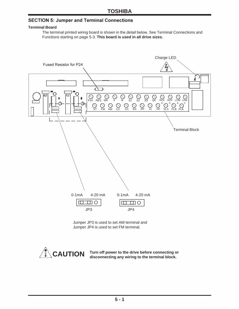
Terminal BoardThe terminal printed wiring board is shown in the detail below. See Terminal Connections andFunctions starting on page 5-3. This board is used in all drive sizes.
5 - 1
Charge LED
Terminal Block
ST FM AM CC CC RX PP IV FP FLC FLB FLA
P24 RES RR F R S1 S2 S3 S4 RCHA
RCHC
LOWA
LOWC
JP3
0-1mA 4-20 mA 0-1mA
Jumper JP3 is used to set AM terminal andJumper JP4 is used to set FM terminal.
4-20 mA
JP4
CAUTION Turn off power to the drive before connecting ordisconnecting any wiring to the terminal block.
SECTION 5: Jumper and Terminal Connections
Fused Resistor for P24

TOSHIBA
Control BoardThe control printed wiring board is shown in the detail below. This control board is used inall drive sizes.
5 - 2
RS-232Communication
connector
Dip SwitchSW1
(see detail 1this page)
I 5
10V
OptionROMsocket
Operationpanel
connector
Option boardconnector(40-pin)
Ribbon cableconnector
Ribbon cableconnector(back side) Dip Switch SW1
(Detail)
When a 4(0)-20mA reference signal is inputto terminal "IV", set switch SW1 to I
When a 0-10 volt reference signal is input toterminal "IV", set SW1 to V
When a +/- 0-5 volt reference signal is inputto terminal "RX", set SW1 to 5
When a +/- 0-10 volt reference signal isinput to terminal "RX", set SW1 to 10
Make connections to this board only with power off.
Spec
ifica
tions
Prec
autio
nsW
iring
Jum
pers
Pane
lKe
ypad
Para
met
ers
Prog
ram
min
gSe
rvic
eD
imen
sion
sIn
dex
Insp
ectio
n

TOSHIBA
5 - 3
Terminalblock
orbus bar
Terminal Connections and FunctionsTerminal Terminal functions Terminal
name location
L1, L2, L3 Line input supply terminals for models H3-2035 to H3-2330:(R, S, T) Connect to either 3ø, 50Hz, 200VAC or 3ø, 60Hz, 200 to 230VAC.
Line input supply terminals for models H3-4055 to H3-420K: Connect to either 3ø, 50HZ, 400VAC or 3ø, 60Hz, 400 to 460VAC.Drives can be operated on single phase power with whenappropriately derated; contact Toshiba distributor for information.
T1, T2, T3 Motor output terminals. Connect these terminals to a 3-phase(U, V, W) induction motor of the proper voltage, current, and horsepower.
PA, PB Braking resistor output terminals. Connect to an external dynamicbraking resistor (available only on 30 HP and smaller drives).
FLA, FLB, FLC Programmable relay contact output. The contact rating is250VAC - 2A. Default setting closes FLA-FLC and opens FLB-FLCwhen protective function has been activated.
P24 Unregulated 24Vdc power supply (24Vdc, 50mA maximum). P24 isprotected by fused resistor found on the terminal board (see p. 5-1).
RCH(A & C) Programmable relay contact output. Standard setting closescontact when an acc/dec is complete, or when the outputfrequency is within a specified range. Contact rating is 250Vac - 2A.
LOW(A & C) Programmable relay contact output. Standard setting closescontact when a preset low speed or a preset lower limit isreached. Contact rating is 250Vac - 2A.
PP 10 VDC supply typically used to drive potentiometers. Wipers frompots typically connected to "RR" or "RX" terminals.
FM* Programmable analog output. Outputs 0 - 1mA or 4 - 20mA (set byJP4 on terminal board (see section 5.1)). This terminal canbe connected to an external analog meter. Use either an ammeterrated 1mA DC/20 mA DC at full scale or a voltmeter rated 7.5Vdc atfull scale (true analog output). See page 9-23 for programming.
AM* Programmable analog output. Outputs 0 - 1mA or 4 - 20mA (set byJP3 on terminal board (see section 5.1)). This terminal canbe connected to an external analog meter. Use either an ammeterrated 1mA DC/20 mA DC at full scale or a voltmeter rated 7.5Vdc atfull scale (true analog output). See page 9-23 for programming.
FP Dedicated open-collector output. Pulses that are 48, 96, or360-times the output frequency are available according to theparameter settings (must connect external supply through pull-upresistor to measure output).
* Do not make/break connections to these terminals with the drive powered.
Terminalblock
(See page5-1)

TOSHIBA
5 - 4
Terminal Connections and Functions (cont'd)Terminal Terminal functions Terminal
name location
CC This is the common return for all of the input and output terminals.(2-terminals) Do not connect this terminal to ground. Do not connect to GND(E).
RR Programmable analog input. Default setting allows user toinput a 0 - 10VDC signal as a frequency command. Input hasbias/gain adjustments.
IV Programmable analog input. User can input a 0 - 10VDC signal or a4 - 20 mA DC signal as a frequency command (selection of currentor voltage done via dipswitch on control board (see page 5-2).Input has bias gain adjustments.
RX Programmable analog input. User can input a +/- 10VDC or a+/- 5VDC signal as a frequency command (see page 5-2). Inputhas bias/gain adjustments for forward and reverse operation.
ST Programmable digital input. With default setting, shorting terminalto "CC" enables drive. Opening "ST" to "CC" coasts motor.
F Programmable digital input. With default setting, shorting terminalto "CC" gives drive forward run command. Opening "F" to "CC"decels motor to a stop.
R Programmable digital input. With default setting, shorting terminalto "CC" gives drive reverse run command. Opening "R" to "CC"decels motor to a stop.
S1 Programmable digital input. With default setting, shorting "S1" to"CC" gives drive preset speed frequency reference.
S2 Programmable digital input. With default setting, shorting "S3" to"CC" gives drive preset speed frequency reference.
S3 Programmable digital input. With default setting, shorting "S2" to"CC" gives drive preset speed frequency reference.
S4 Programmable digital input. With default setting, shorting "S4" to"CC" gives drive preset speed frequency reference.
RES Programmable digital input. With default setting, shorting "RES" to"CC" resets a tripped drive.
Terminalblock
(See page5-1)
Spec
ifica
tions
Prec
autio
nsW
iring
Jum
pers
Pane
lKe
ypad
Para
met
ers
Prog
ram
min
gSe
rvic
eD
imen
sion
sIn
dex
Insp
ectio
n
TOSHIBA
SECTION 6: Operating PanelOperating Panel Layout
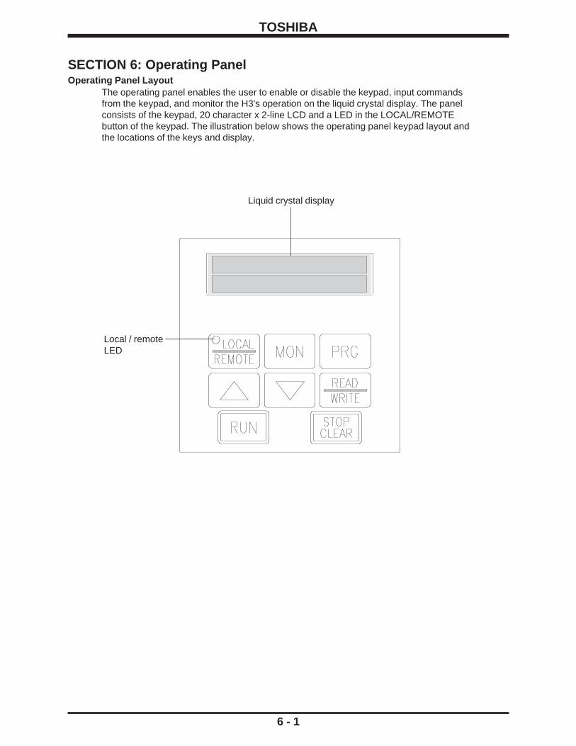
The operating panel enables the user to enable or disable the keypad, input commandsfrom the keypad, and monitor the H3's operation on the liquid crystal display. The panelconsists of the keypad, 20 character x 2-line LCD and a LED in the LOCAL/REMOTEbutton of the keypad. The illustration below shows the operating panel keypad layout andthe locations of the keys and display.
6 - 1
Liquid crystal display
Local / remoteLED

TOSHIBA
LOCAL
REMOTE
Up scroll key used for incrementing numerical values. Also, when a parameter orgroup name is displayed, the name of the previous parameter/group can bedisplayed by pressing this key.
Down scroll key used for decrementing numerical values. Also, when aparameter or group name is displayed, the name of the next parameter/groupcan be displayed by pressing this key.
Used to start a run from the keypad (local control).
Key changes between the local control mode and the terminal block inputcontrol mode operation. When the local control LED in the keypad is "on",operation of the drive is from the keypad.
This key functions as the STOP key when running from keypad (local control). Inall other modes, emergency off is engaged when this key is pressed twice.During a drive trip, the tripped state can be reset by pressing this key twice.
This key is used to enter the monitor mode..
This key is used to select or enter a parameter name, a parameter value, afrequency command, or a group name.
This key is used to enter the programming mode.
6 - 2
Key Function
RUN
PRG
STOPCLEAR
MON
READ
WRITE
Operating Panel Keys and FunctionsThe following chart explains each of the key functions on the keypad
Keys and Functions
Spec
ifica
tions
Prec
autio
nsW
iring
Jum
pers
Pane
lKe
ypad
Para
met
ers
Prog
ram
min
gSe
rvic
eD
imen
sion
sIn
dex
Insp
ectio
n

TOSHIBA
7 - 1
SECTION 7: Keypad Operating Functions
This chapter discusses basic keypad operating functions. The keypad allows the user to enter one of fourmodes: LOCAL, REMOTE, PROGRAMMING, or MONITORING.
LOCAL MODE
Turn on the power source (MCCB). The drive will display OUTPUT FREQUENCY 0.0Hz.
Press the LOCAL/REMOTE button so that the local/remote LED is on. The illuminated LEDindicates that the drive is receiving run/stop commands from the keypad (LOCAL mode).
Set the operating frequency pressing the 'up arrow' or 'down arrow' keys. Notice that displaychanges to FREQUENCY COMMAND.
Press READ/WRITE to save frequency. Display changes back to OUTPUT FREQUENCY.
When the RUN key is pressed, the drive will output a frequency that will increase according tothe set acceleration time. The panel control LED will blink to indicate motor is running.
When the STOP/CLEAR key is pressed, the drive outputs a frequency that will decreaseaccording to the set deceleration time. The motor will decelerate and stop.
If the power switch is turned off while the drive is running a motor, the motor will coast to a stop.This method should be used for emergency stopping only.
The output frequency can be changed while running by pressing up arrow or down arrow key.When one of these keys is pressed the LCD display will blink, indicating that the value is beingchanged. When the desired frequency is shown on the display, press the READ/WRITE key. Theoutput frequency will change even if the READ/WRITE key is not pressed. However, if power isremoved and the READ/WRITE key has not been pressed then the 'new' frequency will be lostbecause it was not written into the EEPROM.
LOCAL MODE: FORWARD/REVERSE CHANGEIn LOCAL mode, motor direction can be changed on the fly from the keypad if Item 25,DIRECTION SELECTION (FORWARD/REV)is set to "1" (its default):
Press READ/WRITE and up arrow at the same time to forward direction command ( drive willbriefly display MOTOR RUN DIRECTION: FORWARD).
Pressing READ/WRITE and down arrow at the same time results in a reverse direction command(drive will briefly display MOTOR RUN DIRECTION: REVERSE).
Reverse runs can be disabled via Item 5, REVERSE OPERATION DISABLE (see page 8-1).
LOCAL MODE: JOGTo jog from the keypad, program Item 108, JOG RUN FREQUENCY and Item 109, JOG STOPMETHOD as desired (see page 8-9).
In LOCAL mode and with display of OUTPUT FREQUENCY, press PRG twice. Drive displaysFORWARD JOG MODE (PRESS RUN). Direction can be changed with up/down arrows.Pressing RUN starts jog. Releasing RUN stops jog according to Item 109, JOG STOP METHOD.
CAUTIONAvoid frequent starting and stopping of the H3 byturning the (MCCB) power on and off. This will shortenthe life of the drive.

TOSHIBA
7 - 2
PROGRAMMING MODE Pressing the PRG button allows users to enter the programming mode. See parameter tree on page 8-33 and parameter charts starting on page 8-1. Parameter explanations and examples can be found in section 9.
LOCAL MODE: COAST STOP
In LOCAL mode, the drive's stop method can be changed to let the motor coast with the following keystrokes.
Keystroke Display Comment OUTPUT FREQUENCY Standard output frequency display
60.0 HZ LOCAL/REMOTE COAST STOP COMMAND Drive prompts user for coast stop command
(PRESS STOP) STOP/CLEAR OUTPUT FREQUENCY Drive immediately stops firing transistors and motor
0.0 HZ coasts to a stop
REMOTE MODEThe drive operates in REMOTE mode when the LOCAL/REMOTE LED is not illuminated. TheLOCAL/REMOTE LED can be turned on and off with the LOCAL/REMOTE key only when thedrive is stopped and at 0.0 Hz. With default programming, the drive powers up in remote mode. Inthe remote mode, the drive is stopped/started remotely (e.g. from the terminal strip). To initiate arun, the drive must have:
1. Drive enable ( e.g. "ST"-"CC" made)2. Frequency command ( e.g. analog input to "IV", "RR", or other termials)3. Direction command ( e.g. "R"-"CC" closure or "F"-"CC" closure )
See pages 5-2 and 4-1 for information on physical connections to the drive. See Items 44-55on page 8-5 for information on the functions available using the input terminals. See Item 281,COMMAND MODE SELECTION and Item 282, FREQUENCY MODE SELECTION for information onhow to set where the drive receives start/stop and frequency commands.
REMOTE MODE: EMERGENCY OFFEMERGENCY OFF can be executed from the keypad when running and operating in remotemode. EMERGENCY OFF is stored as a past fault in the monitor, but does not change the stateof any "fault" contacts. When running in remote mode, press STOP/CLEAR twice to initiate anEMERGENCY OFF command. Drive will stop motor according to method selected in Item 151,EMERGENCY OFF MODE SELECTION.
OTHER KEYPAD FUNCTIONS: LANGUAGE SELECTIONTo change languages, press LOCAL/REMOTE + MON + PRG together with the displayshowing OUTPUT FREQUENCY. Use the arrows to select the desired language and press WRTto enter. As of 8/97, English and German are supported. German is available on the version 121keypad ROM. To check keypad ROM number, press and hold the PRG button after pressing thethree buttons together as mentioned above. If drive displays "79", the keypad ROM is version 121;if the drive displays "6E", the keypad ROM version is 110. If the drive does nothing, keypad ROMis version 100.
Spec
ifica
tions
Prec
autio
nsW
iring
Jum
pers
Pane
lKe
ypad
Para
met
ers
Prog
ram
min
gSe
rvic
eD
imen
sion
sIn
dex
Insp
ectio
n

TOSHIBA
MONITOR MODEPressing the MON key switches the drive to monitor mode. The following table is an example ofthe drive operation variables visible in the monitor:
The monitor has no effect on what is happening to the motor and contains information useful forstart-ups and troubleshooting. If the down/up arrow key is pressed continuously, every 0.5seconds the next/previous item will be displayed.
As illustrated above, the monitor displays MONITOR #1, LOAD CURRENT, INPUT VOLTAGE,and OUTPUT VOLTAGE as default. The four variables displayed in these monitor windows areprogrammable via Items 289-292 (see page 8-30).
Terminals "S6", "S7", and "S8" exist on option boards INV3-COM-B and INV3-COM-D. Terminal"OUT" is an output contact available on option boards INV3-COM-B and INV3-COM-D. "MC" isthe soft start resistor bypass contactor (should always show "ON").
Monitor currents can be shown in amps by adjusting Item 296, CURRENT UNITS SELECTION to"1". Monitor voltages can be shown in percent by adjusting Item 297, VOLTAGE UNITSSELECTION to "0".
The monitor's past four faults can be cleared by setting Item 280, STANDARD SETTING MODESELECTION to "4".
7 - 3
Keystroke Display ExplanationOUTPUT FREQUENCY Standard output frequency display
0.0HzMON MOTOR RUN DIRECTION: Pressing the MON key places drive in monitor
FORWARD mode. The first monitor window indicates direction. down arrow MONITOR #1 Programmable monitor #1
0.0 Hz (the default shows frequency command)down arrow LOAD CURRENT Programmable monitor #2
0% (default setting shows total current in percent) down arrow INPUT VOLTAGE Programmable monitor #3
228V (default setting shows input voltage) down arrow OUTPUT VOLTAGE Programmable monitor #4
0V (default setting shows output voltage)down arrow STATUS: R:-- S1:ON Input terminal monitor. Drive displays "ON"
S2:-- S3:ON S4:-- when terminal is shorted to "CC".down arrow ST:ON F:-- RES:ON Input terminal monitor. Drive displays "ON"
S5:-- S6:ON S7:-- when terminal is shorted to "CC".down arrow RCH:ON LOW:ON FL:ON Output contact monitor. Drive displays "ON" when
OUT:ON FAN:-- MC:ON output is energized.down arrow CUMULATIVE RUN TIME Non-resettable run time monitor. ".01" = 1 hour.
0.00down arrow PAST TRIP #1 Past trip #1 monitor
OVERCURRENT (ACCEL)down arrow PAST TRIP #2 Past trip #2 monitor
OVERCURRENT (DECEL)down arrow PAST TRIP #3 Past trip #3 monitor
OVERVOLTAGE (DECEL)down arrow PAST TRIP #4 Past trip #4 monitor
NO ERRORdown arrow MOTOR RUN DIRECTION: Return to the first monitor window
FORWARD

TOSHIBA
7 - 4
MONITORING "RR" INPUT SPECIAL FUNCTIONThe "RR" terminal can be used to adjust the following drive parameters on the fly: MaximumOutput Frequency, accel/decel times, voltage boost, and stall level. When Item 289, 290, 291, or292 are programmed to "14", one of the drive's monitor windows will display the following:
Setting of Item 79, RR INPUT SPECIAL FUNCTION SELECT Monitor display
1 With 10 volts on the "RR" terminal, this monitor shows MAXIMUM OUTPUT FREQUENCY . Zero volts on "RR" makes the effective
Maximum Output Frequency 30 Hz. See Item 1, MAXIMUM OUTPUT FREQUENCY.
2 This monitor displays the acc/dec multiplier. Zero volts on "RR" results in a display of "1.0". Ten volts on "RR" results in a display of "10.0".3 This monitor displays the effective voltage boost. Zero volts on the "RR" terminal results in a "0.0" display. At ten volts, VOLTAGE
BOOST is displayed.4 This monitor shows effective Stall Protection Current Level. If Item 296,
CURRENT UNITS SELECTION is set to "1", no units will be displayed with the current value.
MONITORING DURING PATTERN RUN During a pattern run, the following four windows are added to the monitor sequence:
Key Operation LCD Message ExplanationOUTPUT FREQUENCY Standard output frequency display
30.0HZMON PATTERN GROUP #1 Indicates the active pattern group number
SPEED #3 and current speed used.down arrow NUMBER OF CYCLES Indicates how many pattern group repetitions
REMAINING 145 are remainingdown arrow PRESET SPEED # 12 Indicates the preset speed currently used.down arrow REMAINING PATTERN Indicates the remaining pattern time
TIME 2365 MIN down arrow MOTOR RUN DIRECTION: Beginning of regular monitor windows.
FORWARD
Spec
ifica
tions
Prec
autio
nsW
iring
Jum
pers
Pane
lKe
ypad
Para
met
ers
Prog
ram
min
gSe
rvic
eD
imen
sion
sIn
dex
Insp
ectio
n

TOSHIBA
8 - 1
*Item 9 is available only when Item 8 Adjustment Range option 1 or 2 is selected.
GROUP:FUNDAMENTAL PARAMETERS #1PARAMETER
DESCRIPTIONLIQUID CRYSTAL DISPLAY ADJUSTMENT
RANGEITEMNO.
PAGENO.
DISPLAYRESOLUTION
FACTORYSETTING
MAXIMUM OUTPUT 1 Maximum frequency 30 - 400 Hz 0.01/0.1 Hz 80 Hz 9-3FREQUENCY
BASE FREQUENCY #1 2 Base frequency #1 25 - 400 Hz 0.01/0.1 Hz 60 Hz 9-3
BASE FREQUENCY 3 Base frequency voltage selection 0: Input voltage level - 1 9-3VOLTAGE SELECT 1: Automatic setting
2: Stationary setting
MAXIMUM OUTPUT 4 Maximum voltage #1 for 230V 0 - 255V 1V 230V 9-3VOLTAGE #1 Maximum voltage #1 for 460V 0 - 510V 1V 460V 9-3
REVERSE OPERATION 5 Reverse operation disable selection 0: Reverse allowed - 0 9-3DISABLE SELECT 1: Reverse not
allowed
UPPER LIMIT 6 Upper limit frequency 0.0 Hz - Maximum 0.01/0.1 Hz 80.0 9-3FREQUENCY Output Frequency
LOWER LIMIT 7 Lower limit frequency 0.0 Hz - Upper 0.01/0.1 Hz 0.0 9-3FREQUENCY Limit Frequency
VOLTS PER HERTZ 8 V/F pattern 1: Constant torque * - 1 9-3PATTERN 2: Variable torque *
3: Automatic torqueboost
4: Automatic torqueboost withautomatic energysavings feature
5: Vector control6: Vector control with
automatic energysavings feature
VOLTAGE BOOST #1 9 * 30 HP and less 0 - 30% 0.1% 3% 9-440 HP and greater 1%
ACCELERATION TIME #1 10 60 HP and less 0.1-6000/0.01-600.0 0.1s/0.01s 10 sec 9-475 HP and greater 60 sec
DECELERATION TIME #1 11 60 HP and less 0.1-6000/0.01-600.0 0.1s/0.01s 10 sec 9-475 HP and greater 60 sec
ACC/DEC PATTERN #1 12 Acc/Dec pattern #1 0: Linear - 0 9-4SELECTION 1: Self-adjusting
2: S-Pattern3: Overspeed Pattern
ACCEL/DECEL PATTERN 13 Acc/Dec pattern adjustment 0 - 50 1% 25 9-5ADJUST LOW amounts (low)
ACCEL/DECEL PATTERN 14 Acc/Dec pattern adjustment 0 - 50 1% 25 9-5ADJUST HIGH amounts (high)
SECTION 8: Programming Charts

TOSHIBA
BASE FREQUENCY #2 15 Base frequency #2 25 - 400 Hz 0.01/0.1 Hz 60.0 9-5
MAXIMUM OUTPUT 16 Maximum voltage #2 for 230V 0 - 255V 1V 230V 9-5VOLTAGE #2 Maximum voltage #2 for 460V 0 - 510V 1V 460V 9-5
VOLTAGE BOOST #2 17 * 30 HP and less 0 - 30% 0.1% 3% 9-540 HP and greater 1%
ELECTRONIC THERMAL 18 Electronic thermal protection 10-100% or amps 1%/A 100 9-5PROTECT LVL #2 level #2
STALL PROTECTION 19 turn stall #2 on/off 0: On ** - 0 9-5SELECTION #2 1: Off
STALL PROTECTION 20** adjust stall current level #2 10-215% or amps 1%/A 120% 9-5LEVEL #2
ACCELERATION TIME #2 21 60 HP and less 0.1-6000/0.01-600.0 0.1s/0.01s 10 sec 9-575 HP and greater 60 sec
DECELERATION TIME #2 22 60 HP and less 0.1-6000/0.01-600.0 0.1s/0.01s 10 sec 9-575 HP and greater 60 sec
ACC/DEC PATTERN #2 23 Acc/Dec pattern #2 0: Linear - 0 9-5SELECTION 1: Self-adjusting
2: S-Pattern3: Overspeed Pattern
ACC/DEC #1/#2 SWITCH 24 Hz at which to switch from 0 - Max. Output Freq. 0.1/0.01 Hz 0.0 9-5FREQUENCY ACC1/DEC1 to ACC2/DEC2 (Item 1)
8 - 2
GROUP:FUNDAMENTAL PARAMETERS #2PARAMETER
DESCRIPTIONLIQUID CRYSTAL DISPLAY ADJUSTMENT
RANGEITEMNO.
PAGENO.
DISPLAYRESOLUTION
FACTORYSETTING
*Item 17 is available only when Item 8, VOLTS PER HERTZ PATTERN Adjustment Range option 1 or 2 is selected.**Item 20 is available only when Item 19 Adjustment Range option 0 is selected.
Spec
ifica
tions
Prec
autio
nsW
iring
Jum
pers
Pane
lKe
ypad
Para
met
ers
Prog
ram
min
gSe
rvic
eD
imen
sion
sIn
dex
Insp
ectio
n

TOSHIBA
DIRECTION SELECTION 25 Forward/reverse 0: Reverse - 1 9-5(FORWARD/REV) 1: Forward
STOP PATTERN 26 Stop pattern selection 0: Decelerated stop - 0 9-5SELECTION 1: Coast stop
FUNDAMENTAL PARAM 27 Fundamental parameter #1 or #2 1: Fundamental - 1 9-5SWITCHING selection parameter #1
2: Fundamentalparameter #2
ACCEL/DECEL #1/#2 28 Acc/dec #1 or #2 1: Acc/dec #1 - 1 9-6SELECTION selection 2: Acc/dec #2
PANEL RESET 29 Panel reset selection 0: All possible - 0 9-6SELECTION 1: Only OL can be
reset2: Only OL, OC1,
OC2, OC3 can bereset
PANEL FEEDBACK 30 Panel feedback control 0: On (valid when - 0 9-6CONTROL (PID, speed feedback, drooping) panel operation is
selected)1: Off (invalid when
panel operation isselected)
8 - 3
GROUP:PANEL CONTROL PARAMETERSPARAMETER
DESCRIPTIONLIQUID CRYSTAL DISPLAY ADJUSTMENT
RANGEITEMNO.
PAGENO.
DISPLAYRESOLUTION
FACTORYSETTING

TOSHIBA
8 - 4
GROUP:SPECIAL CONTROL PARAMETERSPARAMETER
DESCRIPTIONLIQUID CRYSTAL DISPLAY ADJUSTMENT
RANGEITEMNO.
PAGENO.
DISPLAYRESOLUTION
FACTORYSETTING
START-UP FREQUENCY 31 Start-up frequency 0.0 - 10 0.1/0.01 Hz 0.1 9-6
END FREQUENCY 32 End frequency 0.0 - 30 0.1/0.01 Hz 0.1 9-6
RUN FREQUENCY 33 Run frequency 0.0 - max output freq 0.1/0.01 Hz 0.0 9-6
RUN FREQUENCY 34 Run frequency hysteresis 0.0 - 30 0.1/0.01 Hz 0.0 9-6HYSTERESIS
ENABLE JUMP 35 Jump frequency enable 0: Function OFF - 0 9-6FREQUENCIES 1: Function ON *
JUMP FREQUENCY #1 36* Jump frequency #1 0.0-Max Output Freq 0.1/0.01 Hz 0.0 9-6
JUMP FREQUENCY #1 37* +/- band # 1 0 - 30 0.1/0.01 Hz 0.0 9-7BANDWIDTH
JUMP FREQUENCY #2 38* Jump frequency #2 0.0-Max Output Freq 0.1/0.01 Hz 0.0 9-7
JUMP FREQUENCY #2 39* +/- band # 2 0 - 30 0.1/0.01 Hz 0.0 9-7BANDWIDTH
JUMP FREQUENCY #3 40* Jump frequency #3 0.0-Max Output Freq 0.1/0.01 Hz 0.0 9-7
JUMP FREQUENCY #3 41* +/- band # 3 0 - 30 0.1/0.01 Hz 0.0 9-7BANDWIDTH
PWM CARRIER 42 PWM carrier frequency for 230V 500 Hz - 10 kHz 0.1kHz 2.2 kHz 9-7FREQUENCY (.75-30 HP)
PWM carrier frequency for 460V 500 Hz - 10 kHz (1-125 HP)
PWM carrier frequency for 460V 500 Hz - 5 kHz(125-300 HP)
*Items 36 - 41 are available only when Item 35 Adjustment Range option 1 is selected.
Spec
ifica
tions
Prec
autio
nsW
iring
Jum
pers
Pane
lKe
ypad
Para
met
ers
Prog
ram
min
gSe
rvic
eD
imen
sion
sIn
dex
Insp
ectio
n

TOSHIBA
INPUT TERMINAL 43 Input terminal selection 0: Standard terminal - 0 9-7SELECTION functions
1: custom terminalfunctions *
"R" INPUT TERMINAL 44* assign function to "R" terminal 0 - 54 - 0 9-7 FUNCTION (default function is reverse run) 5-1
"S1" INPUT TERMINAL 45* assign function to"S1" terminal 0 - 54 - 1 9-7FUNCTION (default function is preset speed) 5-1
"S2" INPUT TERMINAL 46* assign function to "S2" terminal 0 - 54 - 2 9-7FUNCTION (default function is preset speed) 5-1
"S3" INPUT TERMINAL 47* assign function to "S3" terminal 0 - 54 - 3 9-7FUNCTION (default function is preset speed) 5-1
"S4" INPUT TERMINAL 48* assign function to "S4" terminal 0 - 54 - 4 9-7FUNCTION (default function is preset speed) 5-1
"F" INPUT TERMINAL 49* assign function to "F" terminal 0 - 54 - 5 9-7FUNCTION (default function is forward run) 5-1
"RES" INPUT TERMINAL 50* assign function to "RES" terminal 0 - 54 - 6 9-8FUNCTION (default function is fault reset) 5-1
"ST" INPUT TERMINAL 51* assign function to "ST" terminal 0 - 54 - 7 9-8FUNCTION (default function is drive enable) 5-1
"S5" INPUT TERMINAL 52* assign function to "S5" terminal 0 - 54 - 8 9-8FUNCTION (available on option board)
"S6" INPUT TERMINAL 53* assign function to "S6" terminal 0 - 54 - 9 9-8FUNCTION (available on option board)
"S7" INPUT TERMINAL 54* assign function to "S7" terminal 0 - 54 - 10 9-8FUNCTION (available on option board)
POTENTIAL TERMINAL 55* pick function that is always active 0 - 42 - 33 9-8FUNCTION (no physical connection)
R, S1-S7 TERMINAL 56 "R" and "S1"-"S7" terminals' 1 - 100 1 6 9-10RESPONSE TIME response time 5-1
"F" INPUT TERMINAL 57 "F" terminal response 1 - 100 1 6 9-10RESPONSE TIME time selection 5-1
"RES" INPUT TERMINAL 58 "RES" terminal response 1 - 100 1 6 9-10RESPONSE TIME time selection 5-1
"ST" INPUT TERMINAL 59 "ST" terminal response 1 - 100 1 6 9-10RESPONSE TIME time selection 5-1
"RCH" CONTACTS 60 assign function to "RCH" 0 - 63 1 6 9-10FUNCTION output contact 5-1
"RCH" CONTACTS 61 "RCH" output contact delay time 1 - 100 1 1 9-10DELAY TIME 5-1
"RCH" CONTACTS 62 "RCH" output contact hold time 1 - 100 1 1 9-10HOLD TIME 5-1
8 - 5
GROUP:TERMINAL SELECTION PARAMETERSPARAMETER
DESCRIPTIONLIQUID CRYSTAL DISPLAY ADJUSTMENT
RANGEITEMNO.
PAGENO.
DISPLAYRESOLUTION
FACTORYSETTING
Table continued on next page
*Items 44 - 55 are available only when Item 43 Adjustment Range option 1 is selected.
TOSHIBA
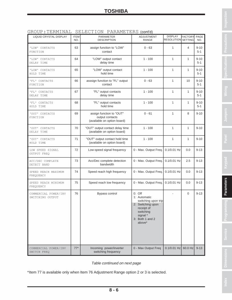
"LOW" CONTACTS 63 assign function to "LOW" 0 - 63 1 4 9-10FUNCTION contact 5-1
"LOW" CONTACTS 64 "LOW" output contact 1 - 100 1 1 9-10DELAY TIME delay time 5-1
"LOW" CONTACTS 65 "LOW" output contact 1 - 100 1 1 9-10HOLD TIME hold time 5-1
"FL" CONTACTS 66 asssign function to "FL" output 0 - 63 1 10 9-10FUNCTION contact 5-1
"FL" CONTACTS 67 "FL" output contacts 1 - 100 1 1 9-10DELAY TIME delay time 5-1
"FL" CONTACTS 68 "FL" output contacts 1 - 100 1 1 9-10HOLD TIME hold time 5-1
"OUT" CONTACTS 69 assign function to "OUT" 0 - 61 1 8 9-10FUNCTION output contacts
(available on option board)
"OUT" CONTACTS 70 "OUT" output contact delay time 1 - 100 1 1 9-10DELAY TIME (available on option board)
"OUT" CONTACTS 71 "OUT" output contact hold time 1 - 100 1 1 9-10HOLD TIME (available on option board)
LOW SPEED SIGNAL 72 Low-speed signal frequency 0 - Max. Output Freq. 0.1/0.01 Hz 0.0 9-13OUTPUT FREQ
ACC/DEC COMPLETE 73 Acc/Dec complete detection 0 - Max. Output Freq. 0.1/0.01 Hz 2.5 9-13DETECT BAND bandwidth
SPEED REACH MAXIMUM 74 Speed reach high frequency 0 - Max. Output Freq. 0.1/0.01 Hz 0.0 9-13FREQUENCY
SPEED REACH MINIMUM 75 Speed reach low frequency 0 - Max. Output Freq. 0.1/0.01 Hz 0.0 9-13FREQUENCY
COMMERCIAL POWER/INV 76 Bypass control 0: Off - 0 9-13SWITCHING OUTPUT 1: Automatic
switching upon trip2: Switching upon
receipt ofswitchingsignal *
3: Both 1 and 2above*
COMMERCIAL POWER/INV 77* Incoming power/inverter 0 - Max Output Freq 0.1/0.01 Hz 60.0 Hz 9-13SWITCH FREQ switching frequency
8 - 6
GROUP:TERMINAL SELECTION PARAMETERS (cont'd)PARAMETER
DESCRIPTIONLIQUID CRYSTAL DISPLAY ADJUSTMENT
RANGEITEMNO.
PAGENO.
DISPLAYRESOLUTION
FACTORYSETTING
Table continued on next page
*Item 77 is available only when Item 76 Adjustment Range option 2 or 3 is selected.
Spec
ifica
tions
Prec
autio
nsW
iring
Jum
pers
Pane
lKe
ypad
Para
met
ers
Prog
ram
min
gSe
rvic
eD
imen
sion
sIn
dex
Insp
ectio
n

TOSHIBA
8 - 7
GROUP:TERMINAL SELECTION PARAMETERS (cont'd)PARAMETER
DESCRIPTIONLIQUID CRYSTAL DISPLAY ADJUSTMENT
RANGEITEMNO.
PAGENO.
FACTORYSETTING
"FP" OUTPUT TERMINAL 78 Output terminal pulse 0: 48 times output frequency 0 9-13PULSE FREQUENCY frequency selection 1: 96 times output frequency 5-1
2: 360 times output frequency
RR INPUT SPECIAL 79 RR input special function selection 0: Standard 0 9-13FUNCTION SELECT 1: Set effective Maximum 5-1
Output Frequency2: Scale ACC/DEC times3: Set effective Voltage Boost4: Set effective Stall Level

TOSHIBA
8 - 8
GROUP:FREQUENCY SETTING PARAMETERSPARAMETER
DESCRIPTIONLIQUID CRYSTAL DISPLAY ADJUSTMENT
RANGEITEMNO.
PAGENO.
DISPLAYRESOLUTION
FACTORYSETTING
Table continued on next page
*Items 84 - 87 are available only when Item 83 Adjustment Range option 1 is selected.**Items 89 - 92 are available only when Item 88 Adjustment Range option 1 is selected.***Items 94 - 97 are available only when Item 93 Adjustment Range option 1 is selected.
FREQUENCY PRIORITY 80 Assign priority to frequency 1:RR terminal - 1 9-13SELECTION #1 reference sources 2:IV terminal
3:RX terminal4:PG input5:Binary input or MOP
FREQUENCY PRIORITY 81 Assign second priority 1:RR terminal 2 9-13SELECTION #2 frequency reference source 2:IV terminal
3:RX terminal4:PG input5:Binary input or MOP
ANALOG INPUT FILTER 82 Analog input filter 0 - 3 - 0 9-14
RR TERMINAL STANDARD 83 RR input selection 0: Standard - 0 9-14OR ADJUSTABLE 1: Adjustable * 5-1
RR REFERENCE SETTING 84* RR reference point #1 0 - 100% 1% 0 9-14POINT #1 of terminal max (10V)
RR REF POINT #1 85* Output frequency desired 0 - Max. Out. Freq. 0.1/0.01 Hz 0.0 9-14FREQUENCY with input entered in Item 84
RR REFERENCE SETTING 86* RR reference point #2 0 - 100% 1% 100 9-14POINT #2 of terminal max (10V)
RR REF POINT #2 87* Output frequency desired 0 - Max.Out. Freq. 0.1/0.01 Hz 80.0 9-14FREQUENCY with input entered in Item 86
IV TERMINAL STANDARD 88 IV input selection 0: Standard - 0 9-14OR ADJUSTABLE 1: Adjustable ** 5-1
IV REFERENCE SETTING 89** IV reference point #1 0 - 100% 1% 20 9-14POINT #1 of terminal maximum
IV REF POINT #1 90** Output frequency desired 0 - Max. Out. Freq. 0.1/0.01 Hz 0.0 9-14FREQUENCY with input entered inItem 89
IV REFERENCE SETTING 91** IV reference point #2 0 - 100% 1% 100 9-14POINT #2 of terminal maximum
IV REF POINT #2 92** Output frequency desired 0 - Max. Out. Freq. 0.1/0.01 Hz 80.0 9-14FREQUENCY with input entered in Item 91
RX TERMINAL STANDARD 93 RX input selection 0: Standard - 0 9-14OR ADJUSTABLE 1: Adjustable *** 5-1
RX REFERENCE SETTING 94*** RX reference point #1 -100 - 100% 1% 0 9-14POINT #1 of terminal maximum
RX REF POINT #1 95*** Output Hz desired with input -Max. Out. Freq. to 0.1/0.01 Hz 0.0 9-14FREQUENCY entered in Item 94 Max. Out. Freq.
RX REFERENCE SETTING 96*** RX reference point #2 -100 - 100% 1% 100 9-14POINT #2 of terminal maximum
RX REF POINT #2 97*** Output Hz desired with input -Max. Out. Freq. to 0.1/0.01 Hz 80.0 9-14FREQUENCY entered in Item 96 Max. Out. Freq.
Spec
ifica
tions
Prec
autio
nsW
iring
Jum
pers
Pane
lKe
ypad
Para
met
ers
Prog
ram
min
gSe
rvic
eD
imen
sion
sIn
dex
Insp
ectio
n

TOSHIBA
8 - 9
GROUP:FREQUENCY SETTING PARAMETERS (cont'd)PARAMETER
DESCRIPTIONLIQUID CRYSTAL DISPLAY ADJUSTMENT
RANGEITEMNO.
PAGENO.
DISPLAYRESOLUTION
FACTORYSETTING
Table continued on next page
*Items 99 - 102 are available only when Item 98 Adjustment Range option 1 is selected.**Items 104 - 107 are available only when Item 103 Adjustment Range option 1 is selected.***Item 109 is available only when Item 108 Adjustment Range is set to other than "0".
PG TERMINAL STANDARD 98 Bias/gain for PG input selection 0: Standard - 0 9-14OR ADJUSTABLE (option board) 1: Adjustable*
PG REFERENCE SETTING 99* PG reference point #1 -100 - 100% of Max. 1% 0 9-14POINT #1 Out. Freq. X PPR
PG REF POINT #1 100* Output Hz desired when reference -Max. Out. Freq. to 0.1/0.01 Hz 0.0 9-14FREQUENCY equals value entered in Item 99 Max. Out. Freq.
PG REFERENCE SETTING 101* PG reference point #2 -100 - 100% of Max. 1% 100 9-14POINT #2 Out. Freq. X PPR
PG REF POINT #2 102* Output Hz desired when reference -Max. Out. Freq. to 0.1/0.01 Hz 80.0 9-14FREQUENCY equals value entered in Item 101 Max. Out. Freq.
BINARY INPUT STD 103 Bias/gain for binary input 0: Standard - 0 9-14OR ADJUSTABLE (via input terminals). 1: Adjustible**
BINARY REF SETTING 104** Binary reference point #1 0 - 100 % 1% 0 9-14POINT #1
BINARY REF POINT #1 105** Output Hz desired when reference -Max. Out. Freq. to 0.1/0.01 Hz 0.0 9-14FREQUENCY equals value entered in Item 104 Max. Out. Freq.
BINARY REF SETTING 106** Binary reference point #2 0 - 100 % 1% 100 9-14POINT #2
BINARY REF POINT #2 107** Output Hz desired when reference -Max. Out. Freq. to 0.1/0.01 Hz 80.0 9-14FREQUENCY equals value entered in Item 106 Max. Out. Freq.
JOG RUN FREQUENCY 108 Jog run frequency 0.0 - 20*** 0.1/0.01 Hz 0.0 9-15
JOG STOP METHOD 109*** Jog stop control 0: Decelerated stop - 0 9-151: Coast to stop2: DC injection
braking

TOSHIBA
PRESET SPEED 110 Selects number of preset speeds 0: Disabled - 0 9-15SELECTION to be unblinded 1: 1st speed only *
2: speeds 1 thru 2 *3: speeds 1 thru 3*4: speeds 1 thru 4*5: speeds 1 thru 5*6: speeds 1 thru 6*7: speeds 1 thru 7*8: speeds 1 thru 8*9: speeds 1 thru 9*10:speeds 1 thru 10*11:speeds 1 thru 11*12:speeds 1 thru 12*13:speeds 1 thru 13*14:speeds 1 thru 14*15:speeds 1 thru 15*
PRESET SPEED MODE 111* Mode selection 0: Deactivated - 0 9-15ACTIVATION 1: Activated
PRESET SPEED #1 112* 1st speed Lower limit frequency 0.1/0.01 Hz 0.0 9-15FREQUENCY to
upper limit frequency
PRESET SPEED #1 113* 1st speed run mode 0: Acc/dec #1, 0 9-15OPERATING MODE forward run
1: Acc/dec #1,reverse run
2: Acc/dec #2,forward run
3: Acc/dec #2,reverse run
4: Acc/dec #1,forward run
5: Acc/dec #1,reverse run
6: Acc/dec #2,forward run
7: Acc/dec #2,reverse run
PRESET SPEED #2 114* 2nd speed Lower limit frequency 0.1/0.01 Hz 0.0 9-15FREQUENCY to
upper limit frequency
PRESET SPEED #2 115* 2nd speed run mode Same options as - 0 9-15OPERATING MODE Item 113
PRESET SPEED #3 116* 3rd speed Lower limit frequency 0.1/0.01 Hz 0.0 9-15FREQUENCY to
upper limit frequency
PRESET SPEED #3 117* 3rd speed run mode Same options as - 0 9-15OPERATING MODE Item 113
8 - 10
GROUP:FREQUENCY SETTING PARAMETERS (cont'd)PARAMETER
DESCRIPTIONLIQUID CRYSTAL DISPLAY ADJUSTMENT
RANGEITEMNO.
PAGENO.
DISPLAYRESOLUTION
FACTORYSETTING
Table continued on next page
*Items 111 - 117 are available only when Item 110 Adjustment Range options 1 - 15 are selected.
Spec
ifica
tions
Prec
autio
nsW
iring
Jum
pers
Pane
lKe
ypad
Para
met
ers
Prog
ram
min
gSe
rvic
eD
imen
sion
sIn
dex
Insp
ectio
n

TOSHIBA
PRESET SPEED #4 118* 4th speed Lower limit frequency 0.1/0.01 Hz 0.0 9-15FREQUENCY to
upper limit frequency
PRESET SPEED #4 119* 4th speed run mode Same options as - 0 9-15OPERATING MODE Item 113
PRESET SPEED #5 120* 5th speed Lower limit frequency 0.1/0.01 Hz 0.0 9-15FREQUENCY to
upper limit frequency
PRESET SPEED #5 121* 5th speed run mode Same options as - 0 9-15OPERATING MODE Item 113
PRESET SPEED #6 122* 6th speed Lower limit frequency 0.1/0.01 Hz 0.0 9-15FREQUENCY to
upper limit frequency
PRESET SPEED #6 123* 6th speed run mode Same options as - 0 9-15OPERATING MODE Item 113
PRESET SPEED #7 124* 7th speed Lower limit frequency 0.1/0.01 Hz 0.0 9-15FREQUENCY to
upper limit frequency
PRESET SPEED #7 125* 7th speed run mode Same options as - 0 9-15OPERATING MODE Item 113
PRESET SPEED #8 126* 8th speed Lower limit frequency 0.1/0.01 Hz 0.0 9-15FREQUENCY to
upper limit frequency
PRESET SPEED #8 127* 8th speed run mode Same options as - 0 9-15OPERATING MODE Item 113
PRESET SPEED #9 128* 9th speed Lower limit frequency 0.1/0.01 Hz 0.0 9-15FREQUENCY to
upper limit frequency
PRESET SPEED #9 129* 9th speed run mode Same options as - 0 9-15OPERATING MODE Item 113
PRESET SPEED #10 130* 10th speed Lower limit frequency 0.1/0.01 Hz 0.0 9-15FREQUENCY to
upper limit frequency
PRESET SPEED #10 131* 10th speed run mode Same options as - 0 9-15OPERATING MODE Item 113
PRESET SPEED #11 132* 11th speed Lower limit frequency 0.1/0.01 Hz 0.0 9-15FREQUENCY to
upper limit frequency
PRESET SPEED #11 133* 11th speed run mode Same options as - 0 9-15OPERATING MODE Item 113
8 - 11
GROUP:FREQUENCY SETTING PARAMETERS (cont'd)PARAMETER
DESCRIPTIONLIQUID CRYSTAL DISPLAY ADJUSTMENT
RANGEITEMNO.
PAGENO.
DISPLAYRESOLUTION
FACTORYSETTING
Table continued on next page
*Items 118 - 133 are available only when Item 110 Adjustment Range options 1 - 15 are selected.

TOSHIBA
PRESET SPEED #12 134* 12th speed Lower limit frequency 0.1/0.01 Hz 0.0 9-15FREQUENCY to
upper limit frequency
PRESET SPEED #12 135* 12th speed run mode Same options as - 0 9-15OPERATING MODE Item 113
PRESET SPEED #13 136* 13th speed Lower limit frequency 0.1/0.01 Hz 0.0 9-15FREQUENCY to
upper limit frequency
PRESET SPEED #13 137* 13th speed run mode Same options as - 0 9-15OPERATING MODE Item 113
PRESET SPEED #14 138* 14th speed Lower limit frequency 0.1/0.01 Hz 0.0 9-15FREQUENCY to
upper limit frequency
PRESET SPEED #14 139* 14th speed run mode Same options as - 0 9-15OPERATING MODE Item 113
PRESET SPEED #15 140* 15th speed Lower limit frequency 0.1/0.01 Hz 0.0 9-15FREQUENCY to
upper limit frequency
PRESET SPEED #15 141* 15th speed run mode Same options as - 0 9-15OPERATING MODE Item 113
8 - 12
GROUP:FREQUENCY SETTING PARAMETERS (cont'd)PARAMETER
DESCRIPTIONLIQUID CRYSTAL DISPLAY ADJUSTMENT
RANGEITEMNO.
PAGENO.
DISPLAYRESOLUTION
FACTORYSETTING
*Items 134 - 141 are available only when Item 110 Adjustment Range options 1 - 15 are selected.
Spec
ifica
tions
Prec
autio
nsW
iring
Jum
pers
Pane
lKe
ypad
Para
met
ers
Prog
ram
min
gSe
rvic
eD
imen
sion
sIn
dex
Insp
ectio
n

TOSHIBA
DYNAMIC BRAKING 142 Dynamic braking selection 0: No DBR used - 0 9-15SELECTION 1: DBR used. Drive's
DBR OL protect off.2: DBR used. Drive'sDBR OL protect on.
BRAKING RESISTOR 143* DBR resistor value 1.0 - 1000 0.1 ohm ***** 9-15VALUE
BRAKING RESISTOR 144* DBR capacity 0.01 - 600 0.01 kW ***** 9-15POWER RATING
OVERVOLTAGE STALL 145 Overvoltage stall protection 0: On - 0 9-16PROTECTION 1: Off
DC INJECTION START 146 DC injection starting frequency 0 - 120 ** 0.1/0.01 Hz 0.0 9-17FREQUENCY
DC INJECTION CURRENT 147** DC injection current 0 - 100% or amps 1 %/A 0 9-17MAGNITUDE
DC INJECTION TIME 148** DC injection time 0 - 10 0.1 sec 0.0 9-17
FWD/REV DC INJECTION 149 DC injection during 0: Off - 0 9-17PRIORITY CTRL direction change 1: On
MOTOR SHAFT 150 continuous DC trickle 0: Off - 0 9-17STATIONARY CTRL 1: On
EMERGENCY OFF MODE 151 Emergency stop selection 0: Coast to stop - 0 9-17SELECTION 1: Decelerated stop
2: DC injectionstop ***
EMERGENCY OFF DC 152*** Emergency stop DC injection time 0 - 10 0.1 sec 0.1 9-17INJECTION TIME
NUMBER OF RETRY 153 Retry selection 0: No retry - 0 9-17ATTEMPTS 1: Retry 1 time ****
2: Retry 2 times ****3: Retry 3 times ****4: Retry 4 times ****5: Retry 5 times ****6: Retry 6 times ****7: Retry 7 times ****8: Retry 8 times ****9: Retry 9 times ****10:Retry 10 times ****
TIME BETWEEN RETRY 154 Retry time setting 0.0 - 10 0.1 sec 1.0 9-17ATTEMPTS ****
8 - 13
GROUP:PROTECTION PARAMETERSPARAMETER
DESCRIPTIONLIQUID CRYSTAL DISPLAY ADJUSTMENT
RANGEITEMNO.
PAGENO.
DISPLAYRESOLUTION
FACTORYSETTING
Table continued on next page
*Items 143 - 144 are available only when Item 142 Adjustment Range option 2 is selected.** Items 147 - 148 are available only when Item 146 Adjustment Range is set to other than "0".*** Item 152 is available only when Item 151 Adjustment Range option 2 is selected.**** Item 154 is available only when Item 153 Adjustment Range options 1 - 10 are selected.***** Default wattage and ohm values depend on the inverter size.

TOSHIBA
REGENERATION POWER 155 allows drive to use regen 0: Off - 0 9-17RIDE-THROUGH for control power 1: On *
REGENERATION RIDE- 156* maximum allowable 0.0 - 25 0.1 sec 2.0 9-17THROUGH TIME ride-through time
AUTO-RESTART (MOTOR 157 "catch" a spinning motor 0: Off - 0 9-17SPEED SEARCH) (forward or reverse) 1: After momentary
power failure (ride-through)2: After "ST" is
shorted to "CC"3: Both 1 and 2
ELECTRONIC THERMAL 158 sets drive's overload to 10-100% or amps 1%/A 100 9-18PROTECT LVL 1 protect motor
OVERLOAD REDUCTION 159 frequency at which drive's motor 0 - 30 0.1/0.01 Hz 30.0 9-18START FREQ overload becomes speed sensitive
MOTOR 150% OVERLOAD 160 sets motor overload time 10 - 2400 10 sec 600 9-18TIME LIMIT
OVERLOAD SELECTION 161 OL selection 0: Standard - 0 9-181: Soft stall on2: Motor OL trip off3: Soft stall on,
Motor OL trip off
STALL PROTECTION 162 Stall protection #1 0: On ** - 0 9-18ENABLE 1: Off
STALL PROTECTION 163** sets current limit 10 - 215%/A 1 %/A 120 9-18CURRENT LEVEL
UNDERVOLTAGE TRIP 164 Undervoltage detection can 0: Trip disabled - 0 9-18SELECTION cause a warning or a trip 1: Trip enabled
UNDERVOLTAGE DETECT 165 Undervoltage detection time 0 - 10 0.01 sec 0.03 9-18TIME
LOW CURRENT DETECT 166 Low current detection can 0: Trip disabled - 0 9-18SELECTION cause a warning or a trip 1: Trip enabled
LOW CURRENT DETECT 167 Low current detection level 0 - 100% or amps 1%/A 0 9-19LEVEL
LOW CURRENT 168 Low current detection time 0 - 255 1 sec 0 9-19DETECTION TIME
OUTPUT SHORT-CIRCUIT 169 Output short-circuit detection 0: Standard - 0 9-19DETECTION SELECT selection (OCL) 1: Less sensitive
short-circuit checki2: Short-circuit check
at power up only3: Combination of
1 and 2 above
8 - 14
GROUP:PROTECTION PARAMETERS (cont'd)PARAMETER
DESCRIPTIONLIQUID CRYSTAL DISPLAY ADJUSTMENT
RANGEITEMNO.
PAGENO.
DISPLAYRESOLUTION
FACTORYSETTING
Table continued on next page
*Item 156 is available only when Item 155 Adjustment Range option 1 is selected.**Item 163 is available only when Item 162 Adjustment Range option 0 is selected.
Spec
ifica
tions
Prec
autio
nsW
iring
Jum
pers
Pane
lKe
ypad
Para
met
ers
Prog
ram
min
gSe
rvic
eD
imen
sion
sIn
dex
Insp
ectio
n

TOSHIBA
OVERTORQUE TRIP 170 Overtorque detection can cause 0: Trip disabled - 0 9-19SELECTION a warning or a trip 1: Trip enabled
OVERTORQUE TRIP 171 Overtorque trip level 10-200% or amps 1%/A 150 9-19LEVEL
FAULT TRIP EEPROM 172 Fault trip saving 0: Fault - 0 9-19SAVE ENABLE cleared when
power cycled1: Fault display
retained whenpower cycled*
COOLING FAN CONTROL 173 Cooling fan control selection 0: Automatic fan - 0 9-19SELECTION 1: Fan always on
CUMULATIVE RUN TIMER 174 Cumulative run timer alarm setting 0.00 - 999.9 0.02 175.0 9-19ALARM SETTING (.01 = 1 hour)
8 - 15
GROUP:PROTECTION PARAMETERS (cont'd)PARAMETER
DESCRIPTIONLIQUID CRYSTAL DISPLAY ADJUSTMENT
RANGEITEMNO.
PAGENO.
DISPLAYRESOLUTION
FACTORYSETTING
*This parameter disables the retry function (see Items 153 and 154).

TOSHIBA
PATTERN RUN 175 Pattern run on/off 0: Off - 0 9-19SELECTION 1: On *
PATTERN RUN CONTINUE 176* Pattern run mode 0: Pattern is reset - 0 9-19MODE when inverter
is stopped1: Pattern resumes
with speed ofinterruption andwith time left atinterruption
PATTERN GROUP #1 177* 1st Pattern Group 0: Skip - 1 9-20SPEED #0 1st speed selection 1: Preset speed #1
2: Preset speed #23: Preset speed #34: Preset speed #45: Preset speed #56: Preset speed #67: Preset speed #78: Preset speed #89: Preset speed #910:Preset speed #1011:Preset speed #1112:Preset speed #1213:Preset speed #1314:Preset speed #1415:Preset speed #15
PATTERN GROUP #1 178* 1st Pattern Group Same options as - 2 9-20SPEED #1 2nd speed selection Item 177
PATTERN GROUP #1 179* 1st Pattern Group Same options as - 3 9-20SPEED #2 3rd speed selection Item 177
PATTERN GROUP #1 180* 1st Pattern Group Same options as - 4 9-20SPEED #3 4th speed selection Item 177
PATTERN GROUP #1 181* 1st Pattern Group Same options as - 5 9-20SPEED #4 5th speed selection Item 177
PATTERN GROUP #1 182* 1st Pattern Group Same options as - 6 9-20SPEED #5 6th speed selection Item 177
PATTERN GROUP #1 183* 1st Pattern Group Same options as - 7 9-20SPEED #6 7th speed selection Item 177
PATTERN GROUP #1 184* 1st Pattern Group Same options as - 8 9-20SPEED #7 8th speed selection Item 177
8 - 16
GROUP:PATTERN RUN CONTROL PARAMETERSPARAMETER
DESCRIPTIONLIQUID CRYSTAL DISPLAY ADJUSTMENT
RANGEITEMNO.
PAGENO.
DISPLAYRESOLUTION
FACTORYSETTING
Table continued on next page
*Items 176 - 184 are available only when Item 175 Adjustment Range option 1 is selected.
Spec
ifica
tions
Prec
autio
nsW
iring
Jum
pers
Pane
lKe
ypad
Para
met
ers
Prog
ram
min
gSe
rvic
eD
imen
sion
sIn
dex
Insp
ectio
n

TOSHIBA
PATTERN GROUP #1 185* number of repeats for 1 - 254, 255=infinity - 1 9-20NUMBER OF CYCLES entire pattern group
PATTERN GROUP #2 186* 2nd Pattern Group Same options as - 9 9-20SPEED #0 1st speed selection Item 177
PATTERN GROUP #2 187* 2nd Pattern Group Same options as - 10 9-20SPEED #1 2nd speed selection Item 177
PATTERN GROUP #2 188* 2nd Pattern Group Same options as - 11 9-20SPEED #2 3rd speed selection Item 177
PATTERN GROUP #2 189* 2nd Pattern Group Same options as - 12 9-20SPEED #3 4th speed selection Item 177
PATTERN GROUP #2 190* 2nd Pattern Group Same options as - 13 9-20SPEED #4 5th speed selection Item 177
PATTERN GROUP #2 191* 2nd Pattern Group Same options as - 14 9-20SPEED #5 6th speed selection Item 177
PATTERN GROUP #2 192* 2nd Pattern Group Same options as - 15 9-20SPEED #6 7th speed selection Item 177
PATTERN GROUP #2 193* 2nd Pattern Group Same options as - 0 9-20SPEED #7 8th speed selection Item 177
PATTERN GROUP #2 194* number of repeats of 1 - 254, 255=infinity - 1 9-20NUMBER OF CYCLES entire pattern group
PATTERN GROUP #3 195* 3rd Pattern Group Same options as - 1 9-20SPEED #0 1st speed selection Item 177
PATTERN GROUP #3 196* 3rd Pattern Group Same options as - 2 9-20SPEED #1 2nd speed selection Item 177
PATTERN GROUP #3 197* 3rd Pattern Group Same options as - 3 9-20SPEED #2 3rd speed selection Item 177
PATTERN GROUP #3 198* 3rd Pattern Group Same options as - 4 9-20SPEED #3 4th speed selection Item 177
8 - 17
GROUP:PATTERN RUN CONTROL PARAMETERS (cont'd)PARAMETER
DESCRIPTIONLIQUID CRYSTAL DISPLAY ADJUSTMENT
RANGEITEMNO.
PAGENO.
DISPLAYRESOLUTION
FACTORYSETTING
Table continued on next page
*Items 185 - 198 are available only when Item 175 Adjustment Range option 1 is selected.

TOSHIBA
PATTERN GROUP #3 199* 3rd Pattern Group Same options as - 5 9-20SPEED #4 5th speed selection Item 177
PATTERN GROUP #3 200* 3rd Pattern Group Same options as - 6 9-20SPEED #5 6th speed selection Item 177
PATTERN GROUP #3 201* 3rd Pattern Group Same options as - 7 9-20SPEED #6 7th speed selection Item 177
PATTERN GROUP #3 202* 3rd Pattern Group Same options as - 8 9-20SPEED #7 8th speed selection Item 177
PATTERN GROUP #3 203* number of repeats of 1 - 254, 255=infinity - 1 9-20NUMBER OF CYCLES entire pattern group
PATTERN GROUP #4 204* 4th Pattern Group Same options as - 9 9-20SPEED #0 1st speed selection Item 177
PATTERN GROUP #4 205* 4th Pattern Group Same options as - 10 9-20SPEED #1 2nd speed selection Item 177
PATTERN GROUP #4 206* 4th Pattern Group Same options as - 11 9-20SPEED #2 3rd speed selection Item 177
PATTERN GROUP #4 207* 4th Pattern Group Same options as - 12 9-20SPEED #3 4th speed selection Item 177
PATTERN GROUP #4 208* 4th Pattern Group Same options as - 13 9-20SPEED #4 5th speed selection Item 177
PATTERN GROUP #4 209* 4th Pattern Group Same options as - 14 9-20SPEED #5 6th speed selection Item 177
PATTERN GROUP #4 210* 4th Pattern Group Same options as - 15 9-20SPEED #6 7th speed selection Item 177
PATTERN GROUP #4 211* 4th Pattern Group Same options as - 0 9-20SPEED #7 8th speed selection Item 177
PATTERN GROUP #4 212* number of repeats of 1 - 254, 255=infinity - 1 9-20NUMBER OF CYCLES entire pattern group
8 - 18
GROUP:PATTERN RUN CONTROL PARAMETERS (cont'd)PARAMETER
DESCRIPTIONLIQUID CRYSTAL DISPLAY ADJUSTMENT
RANGEITEMNO.
PAGENO.
DISPLAYRESOLUTION
FACTORYSETTING
Table continued on next page
*Items 199 - 212 are available only when Item 175 Adjustment Range option 1 is selected.
Spec
ifica
tions
Prec
autio
nsW
iring
Jum
pers
Pane
lKe
ypad
Para
met
ers
Prog
ram
min
gSe
rvic
eD
imen
sion
sIn
dex
Insp
ectio
n
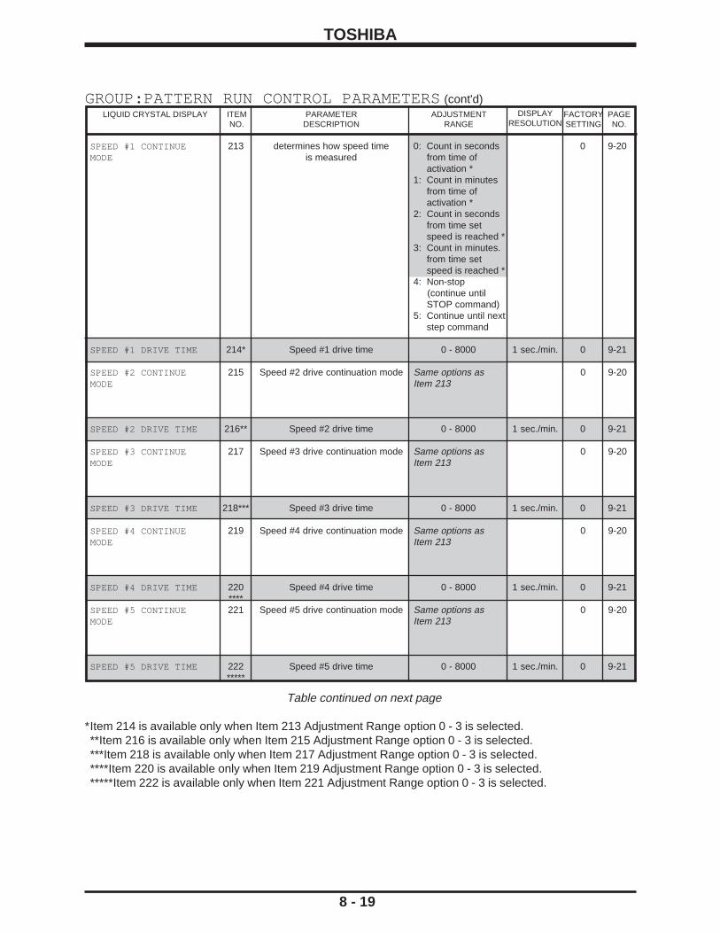
TOSHIBA
SPEED #1 CONTINUE 213 determines how speed time 0: Count in seconds 0 9-20MODE is measured from time of
activation *1: Count in minutes
from time ofactivation *
2: Count in secondsfrom time setspeed is reached *
3: Count in minutes.from time setspeed is reached *
4: Non-stop (continue until
STOP command)5: Continue until next
step command
SPEED #1 DRIVE TIME 214* Speed #1 drive time 0 - 8000 1 sec./min. 0 9-21
SPEED #2 CONTINUE 215 Speed #2 drive continuation mode Same options as 0 9-20MODE Item 213
SPEED #2 DRIVE TIME 216** Speed #2 drive time 0 - 8000 1 sec./min. 0 9-21
SPEED #3 CONTINUE 217 Speed #3 drive continuation mode Same options as 0 9-20MODE Item 213
SPEED #3 DRIVE TIME 218*** Speed #3 drive time 0 - 8000 1 sec./min. 0 9-21
SPEED #4 CONTINUE 219 Speed #4 drive continuation mode Same options as 0 9-20MODE Item 213
SPEED #4 DRIVE TIME 220 Speed #4 drive time 0 - 8000 1 sec./min. 0 9-21****
SPEED #5 CONTINUE 221 Speed #5 drive continuation mode Same options as 0 9-20MODE Item 213
SPEED #5 DRIVE TIME 222 Speed #5 drive time 0 - 8000 1 sec./min. 0 9-21*****
8 - 19
GROUP:PATTERN RUN CONTROL PARAMETERS (cont'd)PARAMETER
DESCRIPTIONLIQUID CRYSTAL DISPLAY ADJUSTMENT
RANGEITEMNO.
PAGENO.
DISPLAYRESOLUTION
FACTORYSETTING
Table continued on next page
*Item 214 is available only when Item 213 Adjustment Range option 0 - 3 is selected.**Item 216 is available only when Item 215 Adjustment Range option 0 - 3 is selected.***Item 218 is available only when Item 217 Adjustment Range option 0 - 3 is selected.****Item 220 is available only when Item 219 Adjustment Range option 0 - 3 is selected.*****Item 222 is available only when Item 221 Adjustment Range option 0 - 3 is selected.

TOSHIBA
SPEED #6 CONTINUE 223 Speed #6 drive continuation mode Same options as - 0 9-20MODE Item 213
SPEED #6 DRIVE TIME 224* Speed #6 drive time 0 - 8000 1 sec./min. 0 9-21
SPEED #7 CONTINUE 225 Speed #7 drive continuation mode Same options as - 0 9-20MODE Item 213
SPEED #7 DRIVE TIME 226** Speed #7 drive time 0 - 8000 1 sec./min. 0 9-21
SPEED #8 CONTINUE 227 Speed #8 drive continuation mode Same options as - 0 9-20MODE Item 213
SPEED #8 DRIVE TIME 228*** Speed #8 drive time 0 - 8000 1 sec./min. 0 9-21
SPEED #9 CONTINUE 229 Speed #9 drive continuation mode Same options as - 0 9-20MODE Item 213
SPEED #9 DRIVE TIME 230 Speed #9 drive time 0 - 8000 1 sec./min. 0 9-21****
SPEED #10 CONTINUE 231 Speed #10 drive continuation mode Same options as - 0 9-20MODE Item 213
SPEED #10 DRIVE TIME 232 Speed #10 drive time 0 - 8000 1 sec./min. 0 9-21*****
8 - 20
GROUP:PATTERN RUN CONTROL PARAMETERS (cont'd)PARAMETER
DESCRIPTIONLIQUID CRYSTAL DISPLAY ADJUSTMENT
RANGEITEMNO.
PAGENO.
DISPLAYRESOLUTION
FACTORYSETTING
Table continued on next page
*Item 224 is available only when Item 223 Adjustment Range option 0 - 3 is selected.**Item 226 is available only when Item 225 Adjustment Range option 0 - 3 is selected.***Item 228 is available only when Item 227 Adjustment Range option 0 - 3 is selected.****Item 230 is available only when Item 229 Adjustment Range option 0 - 3 is selected.*****Item 232 is available only when Item 231 Adjustment Range option 0 - 3 is selected.
Spec
ifica
tions
Prec
autio
nsW
iring
Jum
pers
Pane
lKe
ypad
Para
met
ers
Prog
ram
min
gSe
rvic
eDi
men
sion
sIn
dex
Insp
ectio
n

TOSHIBA
SPEED #11 CONTINUE 233 Speed #11 drive continuation mode Same options as - 0 9-20MODE Item 213
SPEED #11 DRIVE TIME 234* Speed #11 drive time 0 - 8000 1 sec./min. 0 9-21
SPEED #12 CONTINUE 235 Speed #12 drive continuation mode Same options as - 0 9-20MODE Item 213
SPEED #12 DRIVE TIME 236** Speed #12 drive time 0 - 8000 1 sec./min. 0 9-21
SPEED #13 CONTINUE 237 Speed #13 drive continuation mode Same options as - 0 9-20MODE Item 213
SPEED #13 DRIVE TIME 238*** Speed #13 drive time 0 - 8000 1 sec./min. 0 9-21
SPEED #14 CONTINUE 239 Speed #14 drive continuation mode Same options as - 0 9-20MODE Item 213
SPEED #14 DRIVE TIME 240 Speed #14 drive time 0 - 8000 1 sec./min. 0 9-21****
SPEED #15 CONTINUE 241 Speed #15 drive continuation mode Same options as - 0 9-20MODE Item 213
SPEED #15 DRIVE TIME 242 Speed #15 drive time 0 - 8000 1 sec./min. 0 9-21*****
8 - 21
GROUP:PATTERN RUN CONTROL PARAMETERS (cont'd)PARAMETER
DESCRIPTIONLIQUID CRYSTAL DISPLAY ADJUSTMENT
RANGEITEMNO.
PAGENO.
DISPLAYRESOLUTION
FACTORYSETTING
Table continued on next page
*Item 234 is available only when Item 233 Adjustment Range option 0 - 3 is selected.**Item 236 is available only when Item 235 Adjustment Range option 0 - 3 is selected.***Item 238 is available only when Item 237 Adjustment Range option 0 - 3 is selected.****Item 240 is available only when Item 239 Adjustment Range option 0 - 3 is selected.*****Item 242 is available only when Item 241 Adjustment Range option 0 - 3 is selected.

TOSHIBA
8 - 22
LIQUID CRYSTAL DISPLAY PARAMETERDESCRIPTION
ADJUSTMENTRANGE
ITEMNO.
PAGENO.
DISPLAYRESOLUTION
FACTORYSETTING
FEEDBACK CONTROL 243 select type of feedback control 0: No feedback - 0 9-21SELECTION control
1: PID setpointcontrol *
2: Speed feedbackcontrol *
FEEDBACK INPUT 244* Feedback input signal selection 1: "RR" terminal - 2 9-21SIGNAL SELECTION 2: "IV" terminal
3: "RX" terminal4: PG feedback
(option board)5: RS232C input6: RS485 board or
12-bit binary/BCDoption board input
7: Binary input
PROPORTIONAL GAIN 245* Proportional gain 0.01 - 2.55 0.01 0.30 9-21
INTEGRAL GAIN 246* Integral time 0.01 - 360.0 0.01 sec 5.00 9-21
ANTI-HUNTING GAIN 247* Differential time 0.0 - 25.5 0.1 sec 0.0 9-21
LAG TIME CONSTANT 248* Lag time constant 0 - 255 1 80 9-21
PID LOWER LIMIT 249** unique lower limit for PID 0.0 - Max Out Freq 0.1/0.01 Hz 0.0 9-21FREQUENCY
PID DEVIATION LIMIT 250 PID deviation limit selection 0: No PID deviation - 0 9-21SELECTION limit
1: PID deviationlimited***
PID DEVIATION UPPER 251*** PID deviation upper limit 0 - 50% 1% 50 9-21LIMIT
PID DEVIATION LOWER 252*** PID deviation lower limit 0 - 50% 1% 50 9-21LIMIT
PG INPUT: NUMBER OF 253 pulses per rev (for feedback) or 1 - 9999 1 500 9-21PULSES # pulses = 1Hz for pulse reference
PG INPUT: NUMBER OF 254 number of phases 1: Single phase input - 2 9-22PHASES 2: Two-phase input
DROOPING CONTROL 255 load share 0: Off - 0 9-22ENABLE 1: On ****
DROOPING CONTROL 256 Number of Hz droop 0.0 - 10.0% 0.1% 0.0 9-22AMOUNT at full load**** of Max. Out. Freq.
Table continued on next page
*Items 244 - 248 are available only when Item 243 Adjustment Range options 1or 2 are selected.**Item 249 is available only when Item 243 Adjustment Range option 1 is selected.***Items 251 - 252 are available only when Item 250 Adjustment Range option 1 is selected.****Item 256 is available only when Item 255 Adjustment Range option 1 is selected.
GROUP:FEEDBACK PARAMETERS
Spec
ifica
tions
Prec
autio
nsW
iring
Jum
pers
Pane
lKe
ypad
Para
met
ers
Prog
ram
min
gSe
rvic
eD
imen
sion
sIn
dex
Insp
ectio
n

TOSHIBA
8 - 23
GROUP:FEEDBACK PARAMETERS (cont'd)PARAMETER
DESCRIPTIONLIQUID CRYSTAL DISPLAY ADJUSTMENT
RANGEITEMNO.
PAGENO.
DISPLAYRESOLUTION
FACTORYSETTING
OVERRIDE CONTROL 257 trim source 0: Off - 0 9-22SELECTION 1: "RR" terminal
2: "IV" terminal3: "RX" terminal4: PG option board5: Keypad6: All other opt board7: Multiplier
OVERRIDE MULTIPLIER 258* trim source selection 0: Reference - 0 9-22INPUT SELECTION 1: "RR" terminal.
2: "IV" terminal3: "RX" terminal4: Binary input
OVERRIDE CHANGE 259* sets trim range -100.0 - 100.0% 0.1% 0.0 9-22MULTIPLIER of reference
*Items 258 - 259 are available only when Item 257 Adjustment Range option 7 is selected.

TOSHIBA
8 - 24
LIQUID CRYSTAL DISPLAY ADJUSTMENTRANGE
ITEMNO.
PAGENO.
DISPLAYRESOLUTION
FACTORYSETTING
PARAMETERDESCRIPTION
GROUP:COMMUNICATION SETTING PARAMETERS
Cycle power after changing any parameter in GROUP: COMMUNICATION SETTING PARAMETERS.
Table continued on next page
*Items 265 - 266 are available only when Item 264 Adjustment Range option 1 is selected.**Item 267 is available only when Item 264 Adjustment Range option 2 or 3 is selected.
RS232 BAUD RATE 260 set RS232 baud rate 0: 2400 baud - 2 9-221: 4800 baud2: 9600 baud
NUMBER OF DATA BITS 261 Number of data bits 0: 7 bits - 0 9-221: 8 bits
PARITY SETTING 262 Parity 0: Even parity - 0 9-221: Odd parity
INVERTER ID NUMBER 263 Inverter number 0 - 255 - 0 9-22
COMMUNICATION 264 Communication selection 0: Off - 0 9-23SELECTION 1: RS485 board*
2: Tosline-F10, DN board, MB+ board,
RIO board**3: Tosline-S20 **4: 12-bit binary input
(option board)5: BCD board
(0.1 Hz units)6: BCD board
(1 Hz units)
MASTER/SLAVE 265* Master/follower selection 0: Follower - 0 9-23SELECTION 1: Master (follower
follows masterfreq. command)
2: Master (outputfrequency)
RS485 BAUD RATE 266* RS485 baud rate 0: Normal mode - 0 9-231: High speed mode
TOSLINE-F10/S20 267** TOSLINE-F10/TOSLINE-S20 0: Off - 0 9-23COMMAND INPUT command input 1: Frequency
command2: Command input3: Frequency
command,command input
Spec
ifica
tions
Prec
autio
nsW
iring
Jum
pers
Pane
lKe
ypad
Para
met
ers
Prog
ram
min
gSe
rvic
eD
imen
sion
sIn
dex
Insp
ectio
n

TOSHIBA
TOSLINE-F10/S20 268* TOSLINE-F10/TOSLINE-S20 0: Off - 0 9-23MONITOR OUTPUT monitor output 1: Output frequency
2: Status3: Output
frequency, status4: Output current5: Output
frequency,output current
6: Status, outputcurrent
7: Outputfrequency,status,output current
8: Output voltage9: Output
frequency,output voltage
10:Output voltage,status
11:Outputfrequency,output voltage,status
12:Output voltage,output current
13:Output voltage,output current,output frequency
14:Output voltage,output current,status
15:Output voltage,output current,output frequency,status
TOSLINE-F10/S20 COMM 269 TOSLINE-F10 0: Data cleared - 0 9-23ERROR MODE TOSLINE-S20 1: Data retained
communication error mode
RS485/12-BIT BINARY 270 RS485/12-bit binary input: bias 0: Off - 0 0 9-23BIAS, GAIN and gain settings 1: On **
RS485/12-BIT BINARY 271** Point #1 setting signal 0 - 100% of 1% 0 9-23POINT #1 Max. Out. Freq.
RS485/12-BIT BINARY 272** Output Hz desired with input 0 - Max. Out. Freq. 0.1/0.01 Hz 0.0 9-23POINT #1 FREQ entered in Item 271
RS485/12-BIT BINARY 273** Point #2 setting signal 0 - 100% of 100% 100 9-23POINT #2 Max. Out. Freq.
RS485/12-BIT BINARY 274** Output Hz desired with input 0 - Max. Out. Freq. 0.1/0.01 Hz 80.0 9-23POINT #2 FREQ entered in Item 273
8 - 25
GROUP:COMMUNICATION SETTING PARAMETERS (cont'd)PARAMETER
DESCRIPTIONLIQUID CRYSTAL DISPLAY ADJUSTMENT
RANGEITEMNO.
PAGENO.
DISPLAYRESOLUTION
FACTORYSETTING
*Item 268 is available only when Item 264 Adjustment Range option 2 or 3 is selected.**Items 271 - 274 are available only when Item 270 Adjustment Range option 1 is selected.
Cycle power after changing any parameter in GROUP:COMMUNICATION SETTING PARAMETERS.

TOSHIBA
8 - 26
GROUP:INDUSTRIAL APPLICATION PARAMETERS (PUMP)
GROUP:INDUSTRIAL APPLICATION PARAMETERS (FAN)
GROUP:INDUSTRIAL APPLICATION PARAMETERS (CONVEYOR)
GROUP:INDUSTRIAL APPLICATION PARAMETERS (HOIST)
GROUP:INDUSTRIAL APPLICATION PARAMETERS (TEXTILES)
GROUP:INDUSTRIAL APPLICATION PARAMETERS (MACHINE TOOLS)
These groups contain the parameters likely to be used for certain applications. See the H3 IndustrialApplication Manual (available from your Toshiba distributor) for programming charts and macro values.
Spec
ifica
tions
Prec
autio
nsW
iring
Jum
pers
Pane
lKe
ypad
Para
met
ers
Prog
ram
min
gSe
rvic
eD
imen
sion
sIn
dex
Insp
ectio
n

TOSHIBA
8 - 27
GROUP:AM/FM TERMINAL ADJUSTMENT PARAMETERSPARAMETER
DESCRIPTIONLIQUID CRYSTAL DISPLAY ADJUSTMENT
RANGEITEMNO.
PAGENO.
FACTORYSETTING
FM TERMINAL FUNCTION 275 "FM" terminal signal selection 0: Pre-compensation 0 9-23SELECTION ref frequency
1: Post-compensationoutput frequency
2: Frequencyreferencee
3: Output current4: DC voltage5: Output voltage6: Torque current7: Excitation current8: PID feedback
value9: Motor overload
ratio10: Inverter overload
ratio11: DBR overload
ratio12: Input power13:Output power14: Meter calibration (100% fixed output)15: Peak output
current16: Peak input voltage
FREQUENCY METER 276 "FM" terminal calibration - 0.0 Hz 9-24ADJUSTMENT
AM TERMINAL FUNCTION 277 "AM" terminal signal selection 0: Pre-compensation 3 9-25SELECTION reference
frequency1: Post-
compensationoutput frequency
2: Frequency settingvalue
3: Output current4: DC voltage5: Output voltage6: Torque current7: Excitation current8: PID feedback
value9: Motor overload
ratio10: Inverter overload
ratio11: DBR overload
ratio12: Input power13: Output power14: Meter calibration (100% fixed output)15: Peak output
current16: Peak input voltage
CURRENT METER 278 "AM" terminal calibration - 0 % 9-25ADJUSTMENT

TOSHIBA
INDUSTRIAL 279 selects application-specific 0: Does nothing 0 9-25APPLICATIONS programming (macros) 1: Pump application
2: Fan application3: Conveyor application4: Hoist application5: Textiles application6: Machine tool application
STANDARD SETTING 280 defaults drive parameters 0: Does nothing 0 9-25MODE SELECTION 1: 50 Hz setting
2: 60 Hz setting3: Default drive to factory settings4: Clear past trips in monitor5: Store user default settings6: Default to user default settings7: Initialize inverter typeform
COMMAND MODE 281 selects START/STOP command 0: Only RS232C input valid 4 9-25SELECTION source 1: Terminal input valid
2: Panel input valid3: RS485 option board4: Keypad or terminal strip, as set by LOCAL/REMOTE button.
FREQUENCY MODE 282 selects frequency reference 0: Only RS232C input valid 4 9-25SELECTION source 1: Terminal input valid
2: Panel input valid3: RS485 option board4: Keypad or terminal strip, as set by LOCAL/REMOTE button
PANEL OPERATION MODE * 283 limits keypad's functions 0: Prohibit all key operations 63 9-26SELECTION 1: Perform reset
2: Perform monitor operations3: Perform reset, perform monitor
operations4: Perform emergency stop5: Perform emergency stop,
perform reset6: Perform emergency stop,
perform monitor operations7: Perform emergency stop,
perform monitor operations,perform reset
8: Perform run/stop operations9: Perform run/stop operations,
perform reset10:Perform run/stop operations,
perform monitor operations11:Perform run/stop operations,
perform monitor operations,perform reset
12:Perform run/stop operations,perform emergency stop
13:Perform run/stop operations,perform emergency stop,perform reset
14:Perform run/stop operations,perform emergency stop,perform monitor operations
8 - 28
GROUP:UTILITY PARAMETERSPARAMETER
DESCRIPTIONLIQUID CRYSTAL DISPLAY ITEM
NO.PAGENO.
FACTORYSETTING
ADJUSTMENTRANGE
(cont'd)
Table continued on next page* NOTE: Recycle power after changing ITEM 283, PANEL OPERATION MODE SELECTION. ESTOPfrom keypad while in remote mode cannot be disabled.
Spec
ifica
tions
Prec
autio
nsW
iring
Jum
pers
Pane
lKe
ypad
Para
met
ers
Prog
ram
min
gSe
rvic
eD
imen
sion
sIn
dex
Insp
ectio
n

TOSHIBA
8 - 29
GROUP:UTILITY PARAMETERS (cont'd)PARAMETER
DESCRIPTIONLIQUID CRYSTAL DISPLAY ITEM
NO.PAGENO.
FACTORYSETTING
ADJUSTMENTRANGE
(cont'd from p.8-28)
* NOTE: Recycle power after changing ITEM 283, PANEL OPERATION MODE SELECTION.
PANEL OPERATION MODE * 283 Panel operation mode selection 15:Perform run/stop operations, 63 9-26SELECTION perform emergency stop,
perform monitor operations,perform reset
16:Perform parameter readoperations
17:Option 16 + Option 118:Option 16 + Option 219:Option 16 + Option 320:Option 16 + Option 421:Option 16 + Option 522:Option 16 + Option 623:Option 16 + Option 724:Option 16 + Option 825:Option 16 + Option 926:Option 16 + Option 1027:Option 16 + Option 1128:Option 16 + Option 1229:Option 16 + Option 1330:Option 16 + Option 1431:Option 16 + Option 1532:Perform parameter change
operations33:Option 32 + Option 134:Option 32 + Option 235:Option 32 + Option 336:Option 32 + Option 437:Option 32 + Option 538:Option 32 + Option 639:Option 32 + Option 740:Option 32 + Option 841:Option 32 + Option 942:Option 32 + Option 1043:Option 32 + Option 1144:Option 32 + Option 1245:Option 32 + Option 1346:Option 32 + Option 1447:Option 32 + Option 1548:Option 32 + Option 1649:Option 32 + Option 1750:Option 32 + Option 1851:Option 32 + Option 1952:Option 32 + Option 2053:Option 32 + Option 2154:Option 32 + Option 2255:Option 32 + Option 2356:Option 32 + Option 2457:Option 32 + Option 2558:Option 32 + Option 2659:Option 32 + Option 2760:Option 32 + Option 2861:Option 32 + Option 2962:Option 32 + Option 3063:Standard mode (perform all
operations)
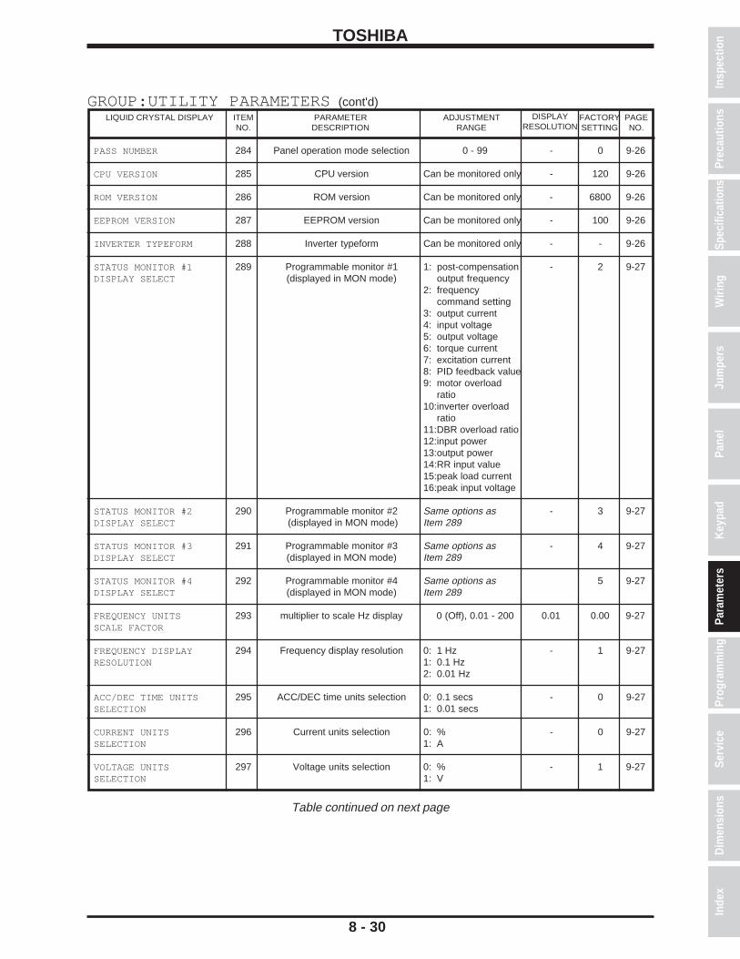
TOSHIBA
PASS NUMBER 284 Panel operation mode selection 0 - 99 - 0 9-26
CPU VERSION 285 CPU version Can be monitored only - 120 9-26
ROM VERSION 286 ROM version Can be monitored only - 6800 9-26
EEPROM VERSION 287 EEPROM version Can be monitored only - 100 9-26
INVERTER TYPEFORM 288 Inverter typeform Can be monitored only - - 9-26
STATUS MONITOR #1 289 Programmable monitor #1 1: post-compensation - 2 9-27DISPLAY SELECT (displayed in MON mode) output frequency
2: frequencycommand setting
3: output current4: input voltage5: output voltage6: torque current7: excitation current8: PID feedback value9: motor overload
ratio10:inverter overload
ratio11:DBR overload ratio12:input power13:output power14:RR input value15:peak load current16:peak input voltage
STATUS MONITOR #2 290 Programmable monitor #2 Same options as - 3 9-27DISPLAY SELECT (displayed in MON mode) Item 289
STATUS MONITOR #3 291 Programmable monitor #3 Same options as - 4 9-27DISPLAY SELECT (displayed in MON mode) Item 289
STATUS MONITOR #4 292 Programmable monitor #4 Same options as 5 9-27DISPLAY SELECT (displayed in MON mode) Item 289
FREQUENCY UNITS 293 multiplier to scale Hz display 0 (Off), 0.01 - 200 0.01 0.00 9-27SCALE FACTOR
FREQUENCY DISPLAY 294 Frequency display resolution 0: 1 Hz - 1 9-27RESOLUTION 1: 0.1 Hz
2: 0.01 Hz
ACC/DEC TIME UNITS 295 ACC/DEC time units selection 0: 0.1 secs - 0 9-27SELECTION 1: 0.01 secs
CURRENT UNITS 296 Current units selection 0: % - 0 9-27SELECTION 1: A
VOLTAGE UNITS 297 Voltage units selection 0: % - 1 9-27SELECTION 1: V
8 - 30
GROUP:UTILITY PARAMETERS (cont'd)PARAMETER
DESCRIPTIONLIQUID CRYSTAL DISPLAY ADJUSTMENT
RANGEITEMNO.
PAGENO.
DISPLAYRESOLUTION
FACTORYSETTING
Table continued on next page
Spec
ifica
tions
Prec
autio
nsW
iring
Jum
pers
Pane
lKe
ypad
Para
met
ers
Prog
ram
min
gSe
rvic
eD
imen
sion
sIn
dex
Insp
ectio
n
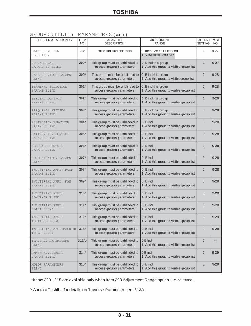
TOSHIBA
8 - 31
GROUP:UTILITY PARAMETERS (cont'd)PARAMETERDESCRIPTION
LIQUID CRYSTAL DISPLAY PAGENO.
FACTORYSETTING
ADJUSTMENTRANGE
ITEMNO.
*Items 299 - 315 are available only when Item 298 Adjustment Range option 1 is selected.
**Contact Toshiba for details on Traverse Parameter Item 313A
BLIND FUNCTION 298 Blind function selection 0: Items 299-315 blinded 0 9-27SELECTION 1: View Items 299-315
FUNDAMENTAL 299* This group must be unblinded to 0: Blind this group 0 9-27PARAMS #2 BLIND access group's parameters 1: Add this group to visible group list
PANEL CONTROL PARAMS 300* This group must be unblinded to 0: Blind this group 0 9-28BLIND access group's parameters 1: Add this group to visiblegroup list
TERMINAL SELECTION 301* This group must be unblinded to 0: Blind this group 0 9-28PARAMS BLIND access group's parameters 1: Add this group to visible group list
SPECIAL CONTROL 302* This group must be unblinded to 0: Blind this group 0 9-28PARAMS BLIND access group's parameters 1: Add this group to visible group list
FREQUENCY SETTING 303* This group must be unblinded to 0: Blind this group 0 9-28PARAMS BLIND access group's parameters 1: Add this group to visible group list
PROTECTION FUNCTION 304* This group must be unblinded to 0: Blind 0 9-28PARAMS BLIND access group's parameters 1: Add this group to visible group list
PATTERN RUN CONTROL 305* This group must be unblinded to 0: Blind 0 9-28PARAMS BLIND access group's parameters 1: Add this group to visible group list
FEEDBACK CONTROL 306* This group must be unblinded to 0: Blind 0 9-28PARAMS BLIND access group's parameters 1: Add this group to visible group list
COMMUNICATION PARAMS 307* This group must be unblinded to 0: Blind 0 9-28BLIND access group's parameters 1: Add this group to visible group list
INDUSTRIAL APPL: PUMP 308* This group must be unblinded to 0: Blind 0 9-28PARAMS BLIND access group's parameters 1: Add this group to visible group list
INDUSTRIAL APPL: FAN 309* This group must be unblinded to 0: Blind 0 9-28PARAMS BLIND access group's parameters 1: Add this group to visible group list
INDUSTRIAL APPL: 310* This group must be unblinded to 0: Blind 0 9-28CONVEYOR BLIND access group's parameters 1: Add this group to visible group list
INDUSTRIAL APPL: 311* Thsi group must be unblinded to 0: Blind 0 9-28HOIST BLIND access group's parameters 1: Add this group to visible group list
INDUSTRIAL APPL: 312* This group must be unblinded to 0: Blind 0 9-29TEXTILES BLIND access group's parameters 1: Add this group to visible group list
INDUSTRIAL APPL:MACHINE 313* This group must be unblinded to 0: Blind 0 9-29TOOLS BLIND access group's parameters 1: Add this group to visible group list
TRAVERSE PARAMETERS 313A* This group must be unblinded to 0:Blind 0 **BLIND access group's parameters 1: Add this group to visible group list
AM/FM ADJUSTMENT 314* This group must be unblinded to 0:Blind 0 9-29PARAMS BLIND access group's parameters 1: Add this group to visible group list
MOTOR PARAMETERS 315* This group must be unblinded to 0: Blind 0 9-29BLIND access group's parameters 1: Add this group to visible group list

TOSHIBA
NUMBER OF MOTOR 316 Number of motor poles 2, 4, 6, 8, 10, 12, 14, 2 4 9-29POLES 16
MOTOR RATED CAPACITY 317 Motor rated capacity 0.1 - 999.9 0.1kW * 9-29
MOTOR TYPE 318 Motor type 0: High efficiency - 0 9-29motor
1: Standard motor2: Other**
MOTOR RATED VOLTAGE 319** Rated voltage for 400V inverter 90 - 600 5V 400 9-29Rated voltage for 200V inverter 90 - 600 5V 200 9-29
MOTOR RATED 320** Rated frequency 0 - 400 2 Hz 60 9-29FREQUENCY
MOTOR RATED RPM 321** Rated RPM 0 - 9999 1 RPM 1710 9-29
AUTO-TUNING ENABLE 322** Auto-tuning *** 0: Auto-tuning - 0 9-29disabled
1: Auto-tuningenabled
LOAD MOMENT OF 323 Load moment of inertia 0: Small - 1 9-29INERTIA 1: Medium
2: Large3: Very large
8 - 32
PARAMETERDESCRIPTION
LIQUID CRYSTAL DISPLAY ADJUSTMENTRANGE
ITEMNO.
PAGENO.
DISPLAYRESOLUTION
FACTORYSETTING
GROUP:MOTOR PARAMETERS
*Item 317 factory setting depends on inverter rating (1 HP = .746kW)**Items 319 - 322 are available only when Item 318 Adjustment Range option 2 is selected.***Inverters sized 150 HP and larger cannot be auto-tuned.
Spec
ifica
tions
Prec
autio
nsW
iring
Jum
pers
Pane
lKe
ypad
Para
met
ers
Prog
ram
min
gSe
rvic
eD
imen
sion
sIn
dex
Insp
ectio
n

TOSHIBA
8 - 33
Parameter Tree
Fundamental Parameters #1
Fundamental Parameters #2
Panel Control Parameters Special Control Parameters
Terminal Selection Parameters
Terminal Selection Parameters (continued)
Frequency Setting Parameters
Frequency Setting Parameters (continued)
1 15 25 31 43 62 80 100
Maximum Output Frequency
Base Frequency #2 Direction Selection Forward/Rev
Start up Frequency Input Terminal Selection
"RCH" Contacts Hold Time
Frequency Priority Selection #1
PG Ref Point #1 Frequency
2 16 26 32 44 63 81 101
Base Frequency #1 Maximum Output Voltage #2
Stop Pattern Selection End Frequency "R" Input Terminal Function
"Low" Contacts Function
Frequency Priority Selection #2
PG Reference Setting Point #2
3 17 27 33 45 64 82 102
Base Frequency Voltage Select
Voltage Boost #2 Fundamental Param Switching
Run Frequency "S1" Input Terminal Function
"Low" Contacts Delay Time
Analog Input Filter PG Ref Point #2 Frequency
4 18 28 34 46 65 83 103
Maximum Output Voltage #1
Electronic Thermal Protect LVL #2
Accel/Decel #1/#2 Selection
Run Frequency Hysteresis
"S2" Input Terminal Function
"Low" Contacts Hold Time
RR Terminal Standard or Adjust.
Binary Input Std. or Adjustable
5 19 29 35 47 66 84 104
Reverse Operation Disable Select
Stall Protection Selection #2
Panel Reset Selection Enable jump Frequencies
"S3" Input Terminal Function
"FL" Contacts Function RR Reference Setting Point #1
Binary Ref Setting Point #1
6 20 30 36 48 67 85 105
Upper Limit Freq. Stall Protection Level #2
Panel Feedback Control
Jump Frequency #1 "S4" Input Terminal Function
"FL" Contacts Delay Time
RR Ref Point #1 Frequency
Binary Ref Point #1 Frequency
7 21 37 49 68 86 106
Lower Limit Freq. Acceleration Time #2 Jump Frequency #1 Bandwidth
"F" Input Terminal Function
"FL" Contacts Hold Time
RR reference Setting Point #2
Binary Ref Setting point #2
8 22 38 50 69 87 107
Volts per hertz Pattern Deceleration Time #2 Jump Frequency #2 "RES" Input Terminal Function
"OUT" Contacts Function
RR Ref Point #2 Frequency
Binary Ref Point #2 Frequency
9 23 39 51 70 88 108
Voltage Boost #1 Acc/Dec Pattern #2 Jump Frequency #2 Bandwidth
"ST" Input Terminal Function
"OUT" Contacts Delay Time
IV Terminal Standard or Adj.
Jog Run Frequency
10 24 40 52 71 89 109
Acceleration Time #1 Acc/Dec #1/#2 Switch Frequency
Jump Frequency #3 "S5" Input Terminal Function
"OUT" Contacts Hold Time
IV Reference Setting Point #1
Jog Stop Method
11 41 53 72 90 110
Deceleration Time #1 Jump Frequency #3 Bandwidth
"S6" Input Terminal Function
Low Speed Signal Output Freq
IV Ref Point #1 Frequency
Preset Speed Selection
12 42 54 73 91 111
Acc/Dec Pattern #1 Selection
PWM Carrier Frequency
"S7" Input Terminal Function
Acc/Dec Complete Detect Band
IV Reference Setting Point #2
Preset Speed Mode Activation
13 55 74 92 112
Accel/Decel Pattern Adjust Low
Potential Terminal Function
Speed Reach Max. Frequency
IV Ref Point #2 Frequency
Preset Speed #1 Frequency
14 56 75 93 113
Accel/Decel Pattern Adjust High
R, S1-S7 Terminal Response Time
Speed Reach Min. Frequency
RX Terminal Standard or Adjust.
Preset Speed #1 Operating Mode
57 76 94 114
"F" Input Terminal Response Time
Commercial Power Inv Switch Output
RX Reference Setting Point #1
Preset Speed #2 Frequency
58 77 95 115
"RES" Terminal Response Time
Commercial Pwr / Inv Switch Freq
RX Ref Point #1 Frequency
Preset Speed #2 Operating Mode
59 78 96 116-139
"ST" Input Terminal Response Time
"FP" Output Terminal Pulse Freq.
RX Reference Setting Point #2
Preset Speeds 3-14 Oper. Modes #3-14
60 79 97 140
"RCH" Contacts Function
RR Input Special Function Select
RX Ref Point #2 Frequency
Preset Speed #15 Frequency
61 98 141
"RCH" Contacts Delay Time
PG Terminal Standard or Adjust.
Preset Speed #15 Operating Mode
99
PG Reference Setting Point #1
LEGEND FOR PARAMETER TREE
Unblinded Group Blinded Group
Item # Item #
Unblinded Parameter Blinded Parameter
600 V G3s HAVE ANOTHER GROUP NOT COVERED IN THIS MANUAL

TOS
HIB
A
8 - 34
Param
eter Tree (cont'd)
Protection Parameters
Protection Parameters
(Continued)Pattern Run Control
Parameters
Feedback Parameters
Comm
unication Setting Param
etersAM
/FM Term
inal Adjustm
ent Parameters
Utility Parameters
Utility Parameters
(Continued)M
otor Parameters
142160
175243
260275
279296
316
Dynamic Braking
SelectionM
otor 150% Overload
Time Lim
itPattern Run Selection
Feedback Control Selection
RS232 Baud RateFM
Terminal Function
SelectionIndustrial Applications
Current Units SelectionNum
ber of Motor Poles
143161
176244
261276
280297
317
Branking Resistor Value
Overload SelectionPattern Run Continue
Mode
Feedback Input Signal Selection
Number of Data Bits
Frequency Meter
Adjustment
Standard Setting Mode
SelectionVoltage Units
SelectionM
otor Rated Capacity
144162
177-184245
262277
281298
318
Braking Resistor Power Rating
Stall Protection EnablePattern Group #1 Speeds #0 - #7
Proportional Gain
Parity SettingAM
Terminal Function
SelectionCom
mand M
ode Selection
Blind Function Selection
Motor Type
145163
185246
263278
282299
319
Overvoltage Stall
ProtectionStall Protection Current Level
Pattern Group #1 Num
ber of CyclesIntegral Gain
Inverter ID Number
Current Meter
Adjustment
Frequency Mode
SelectionFundam
ental Param
eters #2 BlindM
otor Rated Voltage
146164
186-193247
264283
300320
DC Injection Start Frequency
Undervoltage Trip Selection
Pattern Group #2 Speeds #0 - #7
Anti Hunting GainCom
munication
SelectionPanel O
peration Mode
SelectionPanel Control
Parameters Blind
Motor Rated
Frequency
147165
194248
265284
301321
DC Injection Current M
agnituteUndervoltage Detect
Time
Pattern Group #3 Num
ber of CyclesLag Tim
e ConstantM
aster/Slave SelectionPass Num
berTerm
inal Selection Param
eters BlindM
otor Rated RPM
148166
195-202249
266285
302322
DC Injection Time
Low Current Detect Selection
Pattern Group #3 Speeds #0 - #7
PID Lower Frequency Lim
itRS485 Baud Rate
CPU VersionSpecial Control Param
s BlindAuto-Tuning Enable
149167
203250
267286
303323
Fwd/Rev DC Inj. Priority control
Low Current Detect Level
Pattern Group #3 Num
ber of CyclesPID Deviation Lim
it Selection
TOSLINE F10/S20
Comm
and InputROM
VersionFrequency Setting
Params Blind
Load Mom
ent of Inertia
150168
204-211251
268287
304
Motor Shaft stationary
controlLow Current Detection
Time
Pattern Group #4 Speeds #0 - #7
PID Deviation Upper Lim
itTO
SLINE F10/S20 M
onitor OutputEEPROM
VersionProtection Function
Params Blind
151169
212252
269288
305
Emergency Off M
ode Selection
Output Short Circuit Detection Select
Pattern Group #4 Num
ber of CyclesPID Deviation Lower
limit
TOSLINE F10/S20
Comm
Error Mode
Inverter TypeFormPattern Run Control
Params Blind
152170
213253
270289
306
Emergency O
ff DC Injection Tim
eOvertorque Trip
SelectionSpeed #1 Continue
Mode
PG Input Num
ber of Pulses
RS485/12-Bit Binary Bias, G
ainStatus M
onitor #1 Display Select
Feedback Control Param
s Blind
153171
214254
271290
307
Number of Retry
Attempts
Overtorque Trip Level
Speed #1 Drive Time
PG Input Num
ber of Phases
RS485/12-Bit Binary point #1
Status Monitor #2
display SelectCom
munication
Params Blind
154172
215-242255
272291
308
Time Between Retry
Attempts
Fault Trip EEPROM
Save EnableSpeeds 2 - 15 Drive
Time
Drooping Control Enable
RS485/12-Bit Binary pt. #1 Freq
Status Monitor #3
Display SelectIndustrial Appl: Pum
p Param
s Blind
155173
215 - 242256
273292
309
Regeneration Power Ride Through
Cooling Fan Control Selection
Speeds 2-15 Continue m
odeDrooping Control
Amount
RS485/12-Bit Binary point #2
Status Monitor #4
Display SelectIndustrial Appl: Fan
Params Blind
156174
257274
293310
Regeneration Ride Through tim
eCum
ulative Run Timer
Alarm Setting
Override Control Selection
RS485/12-Bit Binary pt. #2 Freq
Frequency Units Scale Factor
Industrial Appl: Conveyor Blind
157258
294311
Auto-restart (motor
speed search)O
verride Multiplier
Input SelectionFrequency Display
ResolutionIndustrial Appl: Hoist
Blind
158259
295312
Electronic Thermal
Protect Level 1Override Change
Multiplier
ACC/DEC Time Units
SelectionIndustrial Appl: Textiles Blind
159313
Overload Reduction
Start Freq.Industrial Appl: Tools
Blind
314
AM/FM
Adjustment
Params Blind
315
Motor Param
eters Blind
Specifications PrecautionsWiringJumpersPanelKeypadParametersProgrammingServiceDimensionsIndex Inspection
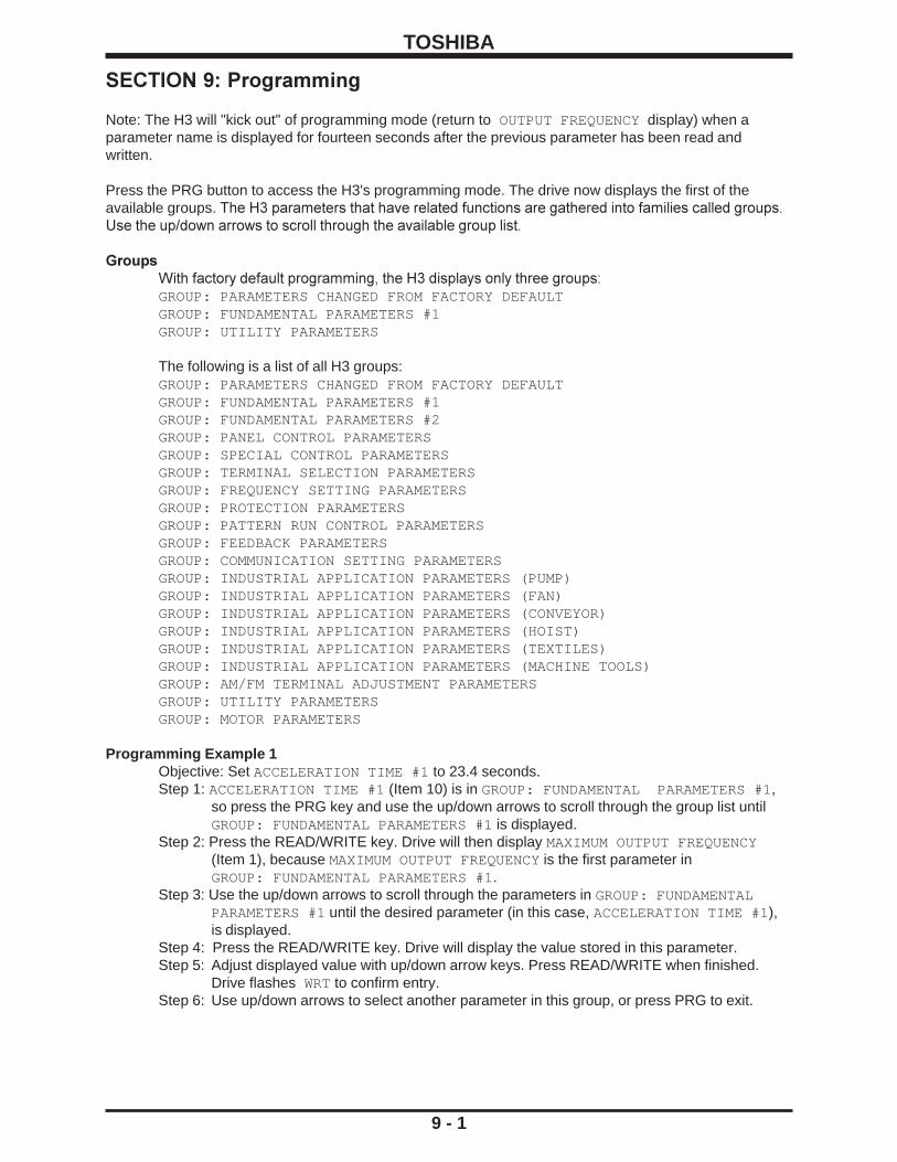
TOSHIBA
9 - 1
SECTION 9: Programming
Note: The H3 will "kick out" of programming mode (return to OUTPUT FREQUENCY display) when aparameter name is displayed for fourteen seconds after the previous parameter has been read andwritten.
Press the PRG button to access the H3's programming mode. The drive now displays the first of theavailable groups. The H3 parameters that have related functions are gathered into families called groups.Use the up/down arrows to scroll through the available group list.
GroupsWith factory default programming, the H3 displays only three groups:GROUP: PARAMETERS CHANGED FROM FACTORY DEFAULTGROUP: FUNDAMENTAL PARAMETERS #1GROUP: UTILITY PARAMETERS
The following is a list of all H3 groups:GROUP: PARAMETERS CHANGED FROM FACTORY DEFAULTGROUP: FUNDAMENTAL PARAMETERS #1GROUP: FUNDAMENTAL PARAMETERS #2GROUP: PANEL CONTROL PARAMETERSGROUP: SPECIAL CONTROL PARAMETERSGROUP: TERMINAL SELECTION PARAMETERSGROUP: FREQUENCY SETTING PARAMETERSGROUP: PROTECTION PARAMETERSGROUP: PATTERN RUN CONTROL PARAMETERSGROUP: FEEDBACK PARAMETERSGROUP: COMMUNICATION SETTING PARAMETERSGROUP: INDUSTRIAL APPLICATION PARAMETERS (PUMP)GROUP: INDUSTRIAL APPLICATION PARAMETERS (FAN)GROUP: INDUSTRIAL APPLICATION PARAMETERS (CONVEYOR)GROUP: INDUSTRIAL APPLICATION PARAMETERS (HOIST)GROUP: INDUSTRIAL APPLICATION PARAMETERS (TEXTILES)GROUP: INDUSTRIAL APPLICATION PARAMETERS (MACHINE TOOLS)GROUP: AM/FM TERMINAL ADJUSTMENT PARAMETERSGROUP: UTILITY PARAMETERSGROUP: MOTOR PARAMETERS
Programming Example 1Objective: Set ACCELERATION TIME #1 to 23.4 seconds.Step 1: ACCELERATION TIME #1 (Item 10) is in GROUP: FUNDAMENTAL PARAMETERS #1,
so press the PRG key and use the up/down arrows to scroll through the group list untilGROUP: FUNDAMENTAL PARAMETERS #1 is displayed.
Step 2: Press the READ/WRITE key. Drive will then display MAXIMUM OUTPUT FREQUENCY(Item 1), because MAXIMUM OUTPUT FREQUENCY is the first parameter inGROUP: FUNDAMENTAL PARAMETERS #1.
Step 3: Use the up/down arrows to scroll through the parameters in GROUP: FUNDAMENTALPARAMETERS #1 until the desired parameter (in this case, ACCELERATION TIME #1 ),is displayed.
Step 4: Press the READ/WRITE key. Drive will display the value stored in this parameter.Step 5: Adjust displayed value with up/down arrow keys. Press READ/WRITE when finished.
Drive flashes WRT to confirm entry.Step 6: Use up/down arrows to select another parameter in this group, or press PRG to exit.

TOSHIBA
9 - 2
BlindingTo make the H3's many parameters more manageable, Toshiba employs "blinded" parametersand "blinded" groups.
BLINDED PARAMETERSItem 9, VOLTAGE BOOST #1, is an example of a "blinded" parameter. A blinded parameter isidentified in the parameter charts (which start on page 8-1) by its gray shading. A "blinded"parameter is preceded by a parameter that has a shaded choice in the Adjustment Range column(like Item 8, VOLTS PER HERTZ PATTERN). Item 9, VOLTAGE BOOST #1, is visible to theprogrammer only if item 8, VOLTS PER HERTZ PATTERN, is set to "1" or "2". Note howAdjustment Range 1 and 2 are shaded to indicate this. There are many other blinded parametersin the H3.
BLINDED GROUPSOf the twenty groups in the H3, only three are accessible when the drive is programmed withfactory defaults. To adjust a parameter that is not in one of the three visible groups, thatparameter's group must first be added to the group list. This is done in GROUP: UTILITYPARAMETERS, which is one of the visible groups.
Programming Example 2Objective: Change ELECTRONIC THERMAL PROTECT LEVEL 1 in GROUP: PROTECTION
PARAMETERS to 89%.Note 1: ELECTRONIC THERMAL PROTECT LEVEL 1 is in a group that is not one of the three
groups visible when the drive is programmed with factory defaults. Therefore, GROUP:PROTECTION PARAMETERS will have to be added to the visible group list.
Note 2: GROUP: PROTECTION PARAMETERS is added to the visible group list by changing item304, PROTECTION FUNCTION PARAMETERS BLIND in GROUP: UTILITYPARAMETERS to "1". To change item 304, however, it must first be unblinded by settingItem 298, BLIND FUNCTION SELECTION in GROUP: UTILITY PARAMETERS to "1".
Step 1: Press PRG and use up arrow to display GROUP: UTILITY PARAMETERS. Press READ/WRITE key. Drive will display INDUSTRIAL APPLICATIONS because it is the firstparameter in the group.
Step 2: Instead of using the down arrow to go through all the parameters in GROUP: UTILITYPARAMETERS, use the up arrow to make the drive display the last visible parameter inGROUP:UTILITY PARAMETERS, which is item 298, BLIND FUNCTION SELECTION.
Step 3: Press READ/WRITE and adjust the "0" to a "1" using the arrow keys. Press READ/WRITE again. Drive flashes WRT to confirm entry.
Step 4: Items 299-315 are now unblinded. Use the down arrow to display PROTECTIONFUNCTION PARAMETERS BLIND. Press READ/WRITE, use the up arrow to change the"0" to a "1", and press READ/WRITE again. Drive flashes WRT to confirm entry.
Step 5: Press PRG twice to return to the group list. Use the arrows to verify that a fourth group,GROUP:PROTECTION PARAMETERS is now a part of the group list.
Step 6: Press READ/WRITE to enter the group. Drive will display Item 142, DYNAMIC BRAKINGSELECTION because that parameter is the first in the group.
Step 7: Use the down arrow to reach Item 158, ELECTRONIC THERMAL PROTECT LEVEL 1.Step 8: Press READ/WRITE. Using the arrows, adjust the value to "89". Press READ/WRT. Drive
flashes WRT to confirm entry.Step 9: Press PRG to leave programming.
Search FunctionWhen GROUP: PARAMETERS CHANGED FROM FACTORY DEFAULT is displayed and READ/WRITE is pressed, the drive will display SEARCHING. Any displayed parameters have beenchanged to a value different from Toshiba's default. Press READ/WRITE to see the value of theparameter. The parameter can be modified with the up/down arrows. Pressing READ/WRITEagain resumes the drive's search.
Spec
ifica
tions
Prec
autio
nsW
iring
Jum
pers
Pane
lKe
ypad
Para
met
ers
Prog
ram
min
gSe
rvic
eD
imen
sion
sIn
dex
Insp
ectio
n

TOSHIBA
9 - 3
Parameter Explanations
GROUP: FUNDAMENTAL PARAMETERS #1 and GROUP: FUNDAMENTAL PARAMETERS #2 allow theuser to store unique V/Hz, accel/decel, etc. parameters for two motors to be operated on one drive atdifferent times.
Item 1, MAXIMUM OUTPUT FREQUENCY - This parameter cannot be changed while the motor is running,and affects accel/decel times, binary frequency references, and many other parameters and functions. Tolimit the drive's ouput frequency range, adjust UPPER LIMIT FREQUENCY and/or LOWER LIMITFREQUENCY (see Items 6 and 7 below).
Item 2, BASE FREQUENCY #1 - This parameter sets the frequency at which the drive's output voltagereaches its maximum.
Item 3, BASE FREQUENCY VOLTAGE SELECTION - The parameter affects the drive's maximum outputvoltage as follows:
0: The output voltage fluctuates with the input voltage.1: The output voltage is set according to the input voltage when the drive is first powered.2: The output voltage is set by Item 4, MAXIMUM OUTPUT VOLTAGE #1.
Item 4, MAXIMUM OUTPUT VOLTAGE #1 - This parameter sets the drive's maximum output voltage. Theoutput voltage cannot exceed the input voltage.
Item 5, REVERSE DISABLE OPERATION SELECTION - The drive will not run in reverse with thisparameter set to '1'.
Item 6, UPPER LIMIT FREQUENCY - This parameter sets the maximum frequency the drive will output,regardless of reference.
Item 7, LOWER LIMIT FREQUENCY - This parameter sets the lowest speed the drive can run, regard-less of reference. If this parameter is set to a non-zero value and the drive is given a run command (i.e.F-CC closure or RUN button), the drive will run at LOWER LIMIT FREQUENCY if the reference is lessthan LOWER LIMIT FREQUENCY.
Item 8, VOLTS PER HERTZ PATTERN - This parameter cannot be changed while the motor is running.The value here sets the way the output voltage changes with output frequency:
1: Constant torque: Drive varies its output voltage linearly with its output hertz change (at 30 Hz, output voltage is approximately half of what it is at 60 Hz).2: Variable torque: Drive varies its output voltage as the square of its output hertz change (at 30 Hz, ouput voltage is approximately 1/4 of what it is was at 60 Hz).3: Automatic torque boost: Drive increases its output voltage at low output Hz to increase motor starting torque.4: Automatic torque boost with energy saving feature: Same as number 3 above, but drive lowers output voltage during lightly-loaded periods (reduces idle amps).5: True torque control: Drive maximizes torque developed by motor and compensates for motor slip. Item 298, BLIND FUNCTION SELECTION and Item 315, MOTOR PARAMETERS BLIND , must also be set to "1" so that GROUP:MOTOR PARAMETERS can be adjusted (see page 8-31).6: True torque control with energy saving feature: Same as number 5 above, but drive lowers output voltage during lightly-loaded periods (reduces idle amps).

TOSHIBA
9 - 4
TIME
commanded frequency
MAXIMUM OUTPUT FREQUENCY
BASE FREQUENCY #1
******** Actual accel time
OU
TP
UT
HZ
MAXIMUM OUTPUT FREQUENCY
commanded frequency
TIME
OU
TP
UT
HZ
* **
***
AT#1
AT#1
* S pattern accel time contributed by Item 13, ACCEL/DECEL PATTERN ADJUST LOW ** S pattern accel time contributed by Item 14, ACCEL/DECEL PATTERN ADJUST HIGH *** Total S pattern accel time Drive follows similar curve during decel.
3: Overspeed pattern - When outputting a frequency greater than the motor's base frequency, drive extends accel/decel time to reduce possibility of overload trip due to reduction in torque.
Parameter Explanations (cont'd)
Item 9, VOLTAGE BOOST #1 - This parameter increases output voltage at low Hz to enable a motoroperated in constant or variable torque modes to develop more starting torque. Too much voltage boostcould result in an overcurrent trip.
Item 10, ACCELERATION TIME #1 (AT#1)AT#1 sets the time for drive output frequency to go from 0 Hz to MAXIMUM OUTPUT FREQUENCY(Item 1). A small acceleration time may result in an overcurrent trip.
Item 11, DECELERATION TIME #1 (DT#1)This parameter sets the time for drive output frequency to go from MAXIMUM OUTPUT FREQUENCY(Item 1) to 0 Hz. A small deceleration time may result in an overvoltage trip.
Item 12, ACC/DEC PATTERN #1This value determines the way the drive's output frequency varies with time during an accel or decel asfollows:
0: Linear pattern - Drive's output frequency change is linear with respect to time. For example, if the output goes from 0 to 30 Hz in 5 seconds, it will take 10 seconds to go from 0 to 60 Hz.
1: Self-adjusting - Drive changes value in AT#1 and DT#1 based on current during accel and bus voltage during decel to prevent overcurrent/overvoltage trips. Every time a run/stop is executed, the drive changes existing data in AT#1 and DT#1 (RAM). Drive may require a few run/stop commands to optimize value. To store modified AT#1 and DT#1 values, read value in AT#1 and DT#1 then press READ/WRITE to write values into memory (EEPROM).
2: S pattern - Drive output frequency's rate of change is slow near beginning and end of accel/ decel.
Spec
ifica
tions
Prec
autio
nsW
iring
Jum
pers
Pane
lKe
ypad
Para
met
ers
Prog
ram
min
gSe
rvic
eD
imen
sion
sIn
dex
Insp
ectio
n

TOSHIBA
9 - 5
Parameter Explanations (cont'd)
Item 13, ACCEL/DECEL PATTERN ADJUST LOW - expressed as a percentage of Item 10, this time isrepresented as "*" in the graph of S Pattern for Item 12.
Item 14, ACCEL/DECEL PATTERN ADJUST HIGH - expressed as a percentage of Item 10, this time isrepresented as "**" in the graph of S Pattern for Item 12.
Note for GROUP:FUNDAMENTAL PARAMETERS #2The parameters in this group are similar to those found in GROUP: FUNDAMENTAL PARAMETERS #1.These two groups allow the user to program the drive for operation with two different motors (only onemotor connected to drive at a time). The user can determine if GROUP: FUNDAMENTAL PARAMETERS #1or if GROUP: FUNDAMENTAL PARAMETERS #2 is active by setting Item 27, FUNDAMENTAL PARAMSWITCHING as desired or by setting one of the drive's input terminal's function to "12" and opening/closingthat terminal to the CC terminal. The user can also determine if ACCELERATION TIME #1/DECELERA-TION TIME #1 or ACCELERATION TIME #2/DECELERATION TIME #2 is active by setting Item 28,ACCEL/DECEL #1/#2 SELECTION or by setting one of the drive's input terminal's functions to "9" andopening/closing that terminal to the CC terminal. See page 9-7 for more information on programming theinput terminals.
Item 15, BASE FREQUENCY #2 - see item 2, BASE FREQUENCY #1
Item 16, MAXIMUM OUTPUT VOLTAGE #2 - see item 4, MAXIMUM OUTPUT VOLTAGE #1
Item 17, VOLTAGE BOOST #2 - see item 9, VOLTAGE BOOST #1
Item 18, ELECTRONIC THERMAL PROTECT LEVEL #2 - This parameter lowers the drive's overload toprotect the motor. Divide motor full-load amps by drive full-load amps and multiply by one hundred. Enterthe result in this parameter. Input in amps with item 296, CURRENT UNITS SELECTION, is set to "1".
Item 19, STALL PROTECTION SELECTION #2 - Stall is a drive function wherein the drive limits themotor current by reducing output voltage and frequency in an effort to reduce load. Stall is most effectiveon variable torque loads. This parameter turns stall off/on.
Item 20, STALL PROTECTION LEVEL #2 - Enter the current limit in amps or in percent of drive rating.See Item 296, CURRENT UNITS SELECTION, to change units from % to amps.
Item 21, ACCELERATION TIME #2 - see item 10, ACCELERATION TIME #1
Item 22, DECELERATION TIME #2 - see item 11, DECELERATION TIME #1
Item 23, ACC/DEC PATTERN #2 SELECTION - see item 12, ACC/DEC PATTERN #1 SELECTION
Item 24, ACC/DEC #1/#2 SWITCHING FREQUENCY - The drive can be programmed to switch fromaccel/decel time #1 to accel/decel time #2 based on output frequency. Enter the Hz at which the driveshould switch from accel/decel time #1 to accel/decel time #2.
Item 25, DIRECTION SELECTION (FORWARD/REVERSE) - This parameter determines direction whencommanding start/stop from keypad. Direction can also be changed from the keypad by pressing READ/WRITE and the up or down arrow simultaneously (with Item 25 set to "1").
Item 26, STOP PATTERN SELECTION - This parameter determines whether the drive follows the decelcurve when the STOP button is pressed or if it performs a coast-stop. Coast stop is also performed whenST-CC is broken.
Item 27, FUNDAMENTAL PARAM SWITCHING - This parameter determines whether GROUP:FUNDAMENTAL PARAMETERS #1 or GROUP:FUNDAMENTAL PARAMETERS #2 is used.

TOSHIBA
9 - 6
Parameter Explanations (cont'd)
Item 28, ACC/DEC #1 OR #2 SELECTION - If the keypad is being used for the RUN/STOP command,then change this parameter to choose which times and pattern are currently utilized. If the drive is gettinga run/stop command via the terminal strip (i.e. "F"-"CC" made or "R"-"CC" made), the user can remotelychoose which accel/decel is used by the drive by programming one of the input terminal's functions (seeitems 44-54) to a value of "9" and then closing this terminal to "CC" when acc/dec #2 is to be used. Seeitem 24, ACC/DEC #1/#2 SWITCH FREQUENCY to change which acc/dec time is used based on drive'soutput Hz.
Item 29, PANEL RESET SELECTION - Use this parameter to limit the type of fault that can be manuallyreset from the panel:
0: Overcurrents, overloads, overvoltages, and overheat1: Only overload faults2: Only overload and overcurrent faults
Item 30, PANEL FEEDBACK CONTROL - Turns feedback on/off when stop/starting from keypad."0" allowskeypad to set setpoint. "1" turns feedback off, letting keypad act as a regular frequency referrence.
Item 31, START-UP FREQUENCY - Drive's output frequency remains at 0 Hz until reference commands anoutput frequency greater than START-UP FREQUENCY. When the reference is great enough, driveimmediately outputs commanded frequency (no accel ramp).
Item 32, END FREQUENCY - Drive's output frequency immediately goes to 0 Hz (no decel ramp) whenreference commands an output frequency less than or equal to END FREQUENCY.
Item 33, RUN FREQUENCY (Frun) - Use in conjunction with item 34, below. This parameter is the center ofthe hysteresis band.
Item 34, RUN FREQUENCY HYSTERESIS (Fhys) - Use this parameter as a +/- bandwidth around RUNFREQUENCY. When the reference signal reaches a value that commands a frequency of Frun+Fhys, thedrive's output frequency will ramp up to the corresponding frequency. The output will continue to followthe reference until the frequency it is commanding falls below Frun-Fhys, at which time the drive will decelto 0 Hz.
Items 33 and 34 are not effective when PID control is operating.
Item 35 JUMP FREQUENCY ENABLE - This parameters allows the programming of "Jump Frequencies",which are bands of output frequencies the drive will not continuously output. The drive allows the user toprogram up to three separate frequencies along with a bandwidth for each.
Item 36 JUMP FREQUENCY #1 - Enter the jump frequency.
HYSTERESIS CHARACTERISTIC
OU
TP
UT
FR
EQ
UE
NC
Y
0 100%FREQUENCY REFERENCE
Start
StopFrun - Fhys
Frun
Frun + Fhys
Spec
ifica
tions
Prec
autio
nsW
iring
Jum
pers
Pane
lKe
ypad
Para
met
ers
Prog
ram
min
gSe
rvic
eD
imen
sion
sIn
dex
Insp
ectio
n

TOSHIBA
9 - 7
Parameter Explanations (cont'd)
Item 37 JUMP FREQUENCY BAND #1 - Enter the bandwidth for JUMP FREQUENCY #1. The valueentered here will be added to and subtracted from JUMP FREQUENCY #1 to determine the upper andlower frequencies of the deadband.
Item 38 JUMP FREQUENCY #2 - see item 36.
Item 39 JUMP FREQUENCY BAND #2 - see item 37.
Item 40 JUMP FREQUENCY #3 - see item 36.
Item 41 JUMP FREQUENCY BAND #3 - see item 37.
Example of Jump Frequency:Suppose JUMP FREQUENCY #1 is set to 30 Hz and JUMP FREQUENCY BAND #1 is set to 5 Hz.Suppose a frequency reference starts commanding 0 Hz and slowly increases. The drive's outputfrequency slowly increases. When the reference hits a level that is commanding 25 Hz (30 - 5 Hz),the drive's output frequency stays at 25 Hz even though the reference continues to increase.When the reference hits a level that commands 35 Hz (30+5 Hz), the drive accelerates (using theselected acceleration time) from 25 Hz to 35 Hz and continues to increase as the referenceincreases. During a decel, the drive will "stick" at 35 Hz until the reference hits a level thatcommands 25 Hz, at which time the drive decelerates (using the selected decel time) from 35 Hzto 25Hz, and resumes following the reference.
Item 42 PWM CARRIER FREQUENCY - Use this function to change the frequency of the motor's acousticnoise. Derate its current capability (110%<= 8Khz, 90%>=10Khz).
Item 43 INPUT TERMINAL SELECTION - With this parameter set to "0", the drive's input terminals, whenshorted to "CC", have the following default functions:"R" terminal gives reverse run command, "F" terminalgives forward run command, "RES" terminal resets a fault, "ST" terminal enables drive, "S1", "S2", "S3",and "S4" terminals give preset speed references. The user has the option of changing the function as-signed to any of the G3's input terminals by programming a "1" into item 43 and programming the followingparameters as necessary.
Item 44, "R" INPUT TERMINAL FUNCTION - sets the function realized when the "R" terminal is shortedto "CC". Default setting gives a reverse run command. See page 9-9 for codes for other availablefunctions.
Item 45, "S1" INPUT TERMINAL FUNCTION - sets the function realized when the "S1" terminal isshorted to "CC". Default setting gives a preset speed reference. See page 9-9 for codes for other availablefunctions.
Item 46, "S2" INPUT TERMINAL FUNCTION - sets the function realized when the "S2" terminal isshorted to "CC". Default setting gives a preset speed reference. See page 9-9 for codes for other availablefunctions.
Item 47, "S3" INPUT TERMINAL FUNCTION - sets the function realized when the "S3" terminal isshorted to "CC". Default setting gives a preset speed reference. See page 9-9 for codes for other availablefunctions.
Item 48, "S4" INPUT TERMINAL FUNCTION - sets the function realized when the "S4" terminal isshorted to "CC". Default setting gives a preset speed reference. See page 9-9 for codes for other availablefunctions.
Item 49, "F" INPUT TERMINAL FUNCTION - sets the function realized when the "F" terminal is shortedto "CC". Default setting gives a forward run command. See page 9-9 for codes for other available

TOSHIBA
9 - 8
Parameter Explanations (cont'd)
Item 50, "RES" INPUT TERMINAL FUNCTION - sets the function realized when the "RES" terminal isshorted to "CC". Default setting resets a fault. See page 9-9 for codes for other available functions.
Item 51, "ST" INPUT TERMINAL FUNCTION - sets the function realized when the "ST" terminal isshorted to "CC". Default setting enables the drive. See page 9-9 for codes for other available functions.
Item 52, "S5" INPUT TERMINAL FUNCTION - sets the function realized when the "S5" terminal isshorted to "CC". Default setting gives a binary speed reference bit. The "S5" terminal is available on theoption boards INV3-COM-B and INV3-COM-D. See page 9-9 for codes for other available functions.
Item 53, "S6" INPUT TERMINAL FUNCTION - sets the function realized when the "S6" terminal isshorted to "CC". Default setting gives a binary speed reference bit. The "S6" terminal is available on theoption boards INV3-COM-B and INV3-COM-D. See page 9-9 for codes for other available functions.
Item 54, "S7" INPUT TERMINAL FUNCTION - sets the function realized when the "S7" terminal isshorted to "CC". Default setting gives a binary speed reference bit. The "S7" terminal is available on theoption boards INV3-COM-B and INV3-COM-D. See page 9-9 for codes for other available functions.
Item 55, POTENTIAL TERMINAL FUNCTION - The potential terminal is an imaginary terminal that thedrive considers always shorted to "CC". Any function code from page 9-9 entered here will always beactive. For example, if a value of "10" is programmed here, the drive will always ESTOP
Notes on input terminals' functions:
1. If the same function is assigned to more than one input terminal, 'OR' logic is in effect.2. If none of the input terminals' function is set to "7" (enable), the drive will assume the drive enabled (just like ST-CC is made).
.
Spec
ifica
tions
Prec
autio
nsW
iring
Jum
pers
Pane
lKe
ypad
Para
met
ers
Prog
ram
min
gSe
rvic
eD
imen
sion
sIn
dex
Insp
ectio
n

TOSHIBA
9 - 9
Parameter Explanations (cont'd)
The following are the functions that are realized when the appropriate drive terminal is shorted to "CC".Program the desired code from the list below into items 44-55 (see). Contact the factory on how tomake a function active when the terminal is disconnected from "CC" (fail-safe).
Code Function 0 Reverse direction command (default for "R" terminal function) 1 Binary coding for number of preset speed desired. Value: +1 (default for "S1" terminal function) 2 Binary coding for number of preset speed desired. Value: +2 (default for "S2" terminal function) 3 Binary coding for number of preset speed desired. Value: +4 (default for "S3" terminal function) 4 Binary coding for number of preset speed desired. Value: +8 (default for "S4" terminal function) 5 Forward direction command (default for "F" terminal function) 6 Reset faults (momentary falling-edge trigger) (default for "RES" terminal function) 7 Drive enable (default for "ST" terminal function) 8 Jog (also need direction command). See items 108 and 109. 9 Select ACC1/DEC1 (open) or ACC2/DEC2 (closed to "CC") 10 Emergency stop. Also see item 151, EMERGENCY OFF MODE SELECTION. 11 DC injection. When outputting a frequency under DC INJECTION START FREQUENCY, short
terminal to "CC" to inject. Also see items 146, 147, and 148. Works in remote mode only. 12 Activate GROUP:FUNDAMENTAL PARAMETERS #1 (open) or GROUP:FUNDAMENTAL
PARAMETERS #2 (closed to "CC") 13 PID off (closed to "CC") or on (open) 14 Select Pattern Run #1 15 Select Pattern Run #2 16 Select Pattern Run #3 17 Select Pattern Run #4 18 Pattern Run continue signal 19 Pattern Run step signal 20 Jog forward (includes forward command). See items 108 and 109. 21 Jog reverse (includes reverse command). See items 108 and 109. 22 Bit #0 for binary speed reference (value of MAXIMUM OUTPUT FREQUENCY/2048) 23 Bit #1 for binary speed reference (value of MAXIMUM OUTPUT FREQUENCY/1024) 24 Bit #2 for binary speed reference (value of MAXIMUM OUTPUT FREQUENCY/512) 25 Bit #3 for binary speed reference (value of MAXIMUM OUTPUT FREQUENCY/256) 26 Bit #4 for binary speed reference (value of MAXIMUM OUTPUT FREQUENCY/128) 27 Bit #5 for binary speed reference (value of MAXIMUM OUTPUT FREQUENCY/64) 28 Bit #6 for binary speed reference (value of MAXIMUM OUTPUT FREQUENCY/32) 29 Bit #7 for binary speed reference (value of MAXIMUM OUTPUT FREQUENCY/16) 30 Bit #8 for binary speed reference (value of MAXIMUM OUTPUT FREQUENCY/8) 31 Bit #9 for binary speed reference (value of MAXIMUM OUTPUT FREQUENCY/4) 32 Bit #10 for binary speed reference (value of MAXIMUM OUTPUT FREQUENCY/2) 33 no function (use terminal to connect wires) 34 Motor operated pot: increase frequency reference 35 Motor operated pot: decrease frequency reference 36 Motor operated pot: clear frequency reference 37 Three wire control: NO momentary start push button 38 Three wire control: NO momentary stop push button. Contact factory for information on how to
realize stop with a NC contact. 40 Forward (open) or reverse (closed to "CC") command 41 Run (use in conjunction with 40 above) 42 Binary data write (use with 22-32 above). If no input terminal's function is set to "42", the drive
responds immediately to binary references commanded by changing data bits. If one of the inputterminal's function is set to "42", the drive responds to binary reference only when terminal isclosed to "CC". Binary reference is lost when power is cycled.
43 emulate LOCAL/REMOTE key 51 Drive/bypass switching signal 53 give "RR" priority over "IV" and "RX" 54 give "IV" priority over "RR" and "RX"

TOSHIBA
9 - 10
Parameter Explanations (cont'd)
Item 56, R,S1-S7 RESPONSE TIME - Use this function to adjust the time between an input terminal'sconnection to "CC" and its function's realization. A setting of "100" results in a delay of about 200milliseconds.
Item 57, "F" INPUT TERMINAL RESPONSE TIME - Use this function to adjust the time between aninput terminal's connection to "CC" and its function's realization. A setting of "100" results in a delay ofabout 200 milliseconds.
Item 58, "RES" INPUT TERMINAL RESPONSE TIME - Use this function to adjust the time between aninput terminal's connection to "CC" and its function's realization. A setting of "100" results in a delay ofabout 200 milliseconds.
Item 59, "ST" INPUT TERMINAL RESPONSE TIME - Use this function to adjust the time between aninput terminal's connection to "CC" and its function's realization. A setting of "100" results in a delay ofabout 200 milliseconds.
Item 60, "RCH" CONTACTS FUNCTION - Enter the code from the table on pages 9-11 and 9-12 todetermine when drive will change the state of this dry output contact. Terminals "RCHA" and "RCHB" areeither side of the contact.
Item 61, "RCH" CONTACTS DELAY TIME - sets the delay between the time the drive senses a desiredcondition and the time at which a change in "RCH" contact indicating this condition occurs. Maximumadjustment of "100" is approximately 200 milliseconds.
Item 62, "RCH" CONTACTS HOLD TIME - Example: Suppose drive is programmed to close "RCH"contact when it is outputting more than 30 Hz. When the drive's output frequency dips below 30 Hz, thecontact will immediately open. Adjusting this parameter to "100" would keep the "RCH" contact closed (i.e."RCHA" to "RCHB" shorted) for an additional 200 milliseconds after the drive outputted less than 30 Hz.
Item 63, "LOW" CONTACTS FUNCTION - See item 60 above.
Item 64, "LOW" CONTACTS DELAY TIME - See item 61 above.
Item 65, "LOW" CONTACTS HOLD TIME - See item 62 above.
Item 66, "FL" CONTACTS FUNCTION - See item 60 above. On terminal strip, normally open contact isbetween "FLA" and "FLC". Normally closed contact is between "FLB" and "FLC".
Item 67, "FL" CONTACTS DELAY TIME - See item 61 above.
Item 68, "FL" CONTACTS HOLD TIME - See item 62 above.
Item 69, "OUT" CONTACTS FUNCTION - See item 60 above. Available on INV3-COM-B andINV3-COM-D option boards (see page 11-4 for more information).
Item 70, "OUT" CONTACTS DELAY TIME - See item 61 above.
Item 71, "OUT" CONTACTS HOLD TIME - See item 62 above.
Spec
ifica
tions
Prec
autio
nsW
iring
Jum
pers
Pane
lKe
ypad
Para
met
ers
Prog
ram
min
gSe
rvic
eD
imen
sion
sIn
dex
Insp
ectio
n

TOSHIBA
9 - 11
Parameter Explanations (cont'd)
Output Contacts' Functions
Value Comments0 Contact will close when drive is at or above Item 7, LOWER LIMIT FREQUENCY1 Contact will close when drive is not at or above LOWER LIMIT FREQUENCY2 Contacts will close when drive is at Item 6, UPPER LIMIT FREQUENCY3 Contacts will close when drive is not at UPPER LIMIT FREQUENCY4 Default for LOWA/LOWC terminals. Contact will close when drive is at or above speed in
Item 72, LOW SPEED SIGNAL OUTPUT FREQUENCY5 Contact will close when drive is not at or above LOW SPEED SIGNAL OUTPUT FREQUENCY6 Default for RCHA/RCHC terminals. Contact closes when any accel or decel is complete.7 Contact closes when any acceleration or deceleration is not complete.8 Contact closes when drive is at or above Item 74, SPEED REACH MAXIMUM FREQUENCY
during an accel or when drive is at or above Item 75, SPEED REACH MINIMUM FREQUENCYduring a decel
9 Contact closes when drive is not at or above SPEED REACH MAXIMUM FREQUENCY during anaccel or when drive is not at or above SPEED REACH MINIMUM FREQUENCY during a decel.
10 Default for FLA/FLB/FLC terminals. Contact closes when drive is faulted (ESTOP is not a fault)11 Contact closes when drive is not faulted (ESTOP is not a fault)12 Contact closes when drive is faulted on anything except EARTH FAULT or LOAD END
OVERCURRENT (ESTOP is not a fault)13 Contact closes when drive is faulted on EARTH FAULT or LOAD END OVERCURRENT14 Contact closes when overcurrent stall is active (use as overcurrent pre-alarm). The stall current
level is adjustable via Item 163 or Item 20 (see).15 Contact closes when overcurrent stall is not active. The stall current level is adjustable via Item
163 or Item 20 (see).16 Contact closes to signify drive overload pre-alarm. Example of drive overload: H3 is rated
for 150% of rated current for 2 minutes. If drive is operated at 150% of rated current for oneminute, the drive overload is at 50%, or half of its overload current-time capability. The drivetrips on overload at 100%. Drive overload pre-alarm starts at 50%.
17 Contact closes to signify drive is not in an overload pre-alarm. See explanation for value 16above.
18 Contact closes to signify motor overload pre-alarm. Example of overload: H3 is rated for 150%of rated current for 2 minutes. If drive is operated at 150% of rated current for one minute, thedrive overload is at 50%, or half of its overload current-time capability. The drive trips onoverload at 100%. Overload pre-alarm starts at 50%.
19 Contact closes to signify motor is not in an overload pre-alarm. See explanation for value 18above.
20 Contact closes when heatsink reaches 84O C. Contact opens at 80O C after it has closed21 Contact closes when heatsink is under 84O C. Contact closes at 80O C after it has opened22 Contact closes when drive is displaying OVERVOLTAGE. See page 10-7.23 Contact closes when drive is not displaying OVERVOLTAGE. See page 10-7.24 Contact closes when drive is displaying DC BUS UNDERVOLTAGE. See page 10-7.25 Contact closes when is not displaying DC BUS UNDERVOLTAGE. See page 10-7.26 Contact closes when output current is at or greater than the current programmed into Item 167,
LOW CURRENT DETECTION LEVEL for longer than the time programmed in Item 168, LOWCURRENT DETECTION TIME
27 Contact closes when output current is not at or greater than the current programmed into LOWCURRENT DETECTION LEVEL for longer than the time programmed in LOW CURRENTDETECTION TIME
28 Contact closes when torque current equals or exceeds the setting programmed into Item 171,OVERTORQUE TRIP LEVEL
29 Contact closes when torque current does not equal or exceed the setting programmed intoOVERTORQUE TRIP LEVEL
Output contact functions continued on next page

TOSHIBA
Parameter Explanations (cont'd)
OUTPUT CONTACTS' FUNCTIONS (con't)
Value Comments30 Contact closes when dynamic braking resistor is half way or more into its overload as
calculated by the drive based upon the setting in Item 143, BRAKING RESISTOR VALUE andItem 144, BRAKING RESISTOR POWER RATING (GROUP:PROTECTION PARAMETERS). Seeexplanation of overload for Value 16 on previous page.
31 Contact closes when dynamic braking resistor is less than half way into its overload ascalculated by the drive based upon the settings in BRAKING RESISTOR VALUE and BRAKINGRESISTOR POWER RATING. See explanation of overload for Value 17 on previous page.
32 Contact closes when drive is executing an ESTOP33 Contact closes when drive is not executing an ESTOP34 Contact closes when drive is executing a retry35 Contact closes when drive is not executing a retry36 Contact closes when drive is running a Pattern Run37 Contact closes when drive is not running a Pattern Run38 Contact closes when the error signal calculated by the drive�s PID equals or exceeds the value
programmed into Item 251, PID DEVIATION UPPER LIMIT or Item 252, PID DEVIATIONLOWER LIMIT (GROUP:FEEDBACK PARAMETERS)
39 Contact closes when the error signal calculated by the drive�s PID does not equal or exceed thevalue programmed into PID DEVIATION UPPER LIMIT or PID DEVIATION LOWER LIMIT
40 Contact closes when drive is running at or above 0.01 Hz.41 Contact closes when drive is not running at or above 0.01 Hz.42 Contact closes when drive is faulted on a �severe� fault (not retryable) *43 Contact closes when drive is not faulted on a �severe� fault *44 Contact closes when drive is tripped on a retryable fault *45 Contact closes when drive is not tripped on a retryable fault *46 Auto-bypass control. Contact closes to energize coil of output contactor.47 Opposite logic state of above48 Auto-bypass control. Contact closes to energize coil of bypass contactor.49 Opposite logic state of above50 Contact closes when drive�s cooling fan(s) is on.51 Contact closes when drive�s cooling fan(s) is not on.52 Contact closes when drive is jogging53 Contact closes when drive is not jogging54 Contact closes when drive is getting RUN/STOP command from the keypad55 Contact closes when drive is not getting RUN/STOP command from the keypad56 Contact closes when drive run time is greater than or equal to time programmed into Item 174,
CUMULATIVE RUN TIMER ALARM SETTING (GROUP:PROTECTION PARAMETERS)57 Contact closes when drive run time is not greater than or equal to time programmed into
CUMULATIVE RUN TIMER ALARM SETTING58 Contact closes when drive trips on a COMMUNICATION ERROR59 Contact closes when drive does not have a COMMUNICATION ERROR60 Contact changes state when drive goes through 0.0 Hz to change direction. Contact is closed/
open during forward/reverse run. Contact maintains current condition at 0.0 Hz when decel iscomplete after a stop command.
61 Contact changes state when drive goes through 0.0 Hz to change direction. Contact is open/closed during forward/reverse run. Contact maintains current condition at 0.0 Hz when decel iscomplete after a stop command.
62 Contact closes when drive has a run command and ST-CC is made63 Contact closes when drive does not have a run command
* Retryable faults include:OVERCURRENT(ACCEL), OVERCURRENT(DECEL), OVERCURRENT(RUN), DC OVERCURENT(ACC), DCOVERCURRENT (DEC), DC OVERCURRENT(RUN), OVERVOLTAGE(ACCEL), OVERVOLTAGE(DECEL),OVERVOLTAGE(RUN), OVERHEAT, MOTOR OVERLOAD, INVERTER OVERLOAD, DBR OVERLOAD TRIP
9 - 12
Spec
ifica
tions
Prec
autio
nsW
iring
Jum
pers
Pane
lKe
ypad
Para
met
ers
Prog
ram
min
gSe
rvic
eD
imen
sion
sIn
dex
Insp
ectio
n

TOSHIBA
9 - 13
Parameter Explanations (cont'd)
Item 72, LOW SPEED SIGNAL OUTPUT FREQUENCY - Use this parameter to set the frequency abovewhich one of the drive's output contacts (RCHA-RCHC, etc) changes state. See Item 60, 63, and 66.
Item 73, ACC/DEC COMPLETE DETECT BAND - If one of the output contacts' function is set to "6"(accel/decel complete), use this parameter to operate the contact when the output frequency is within thisbandwidth (minus during accel, plus during decel) of the frequency command.
Item 74, SPEED REACH MAXIMUM FREQUENCY - Use this parameter to set the output frequency at whichone of the drive's output contacts (RCHA-RCHC, etc.) changes state during an acceleration. See Items60, 63, and 66.
Item 75, SPEED REACH MINIMUM FREQUENCY - Use this parameter to set the output frequency at whichone of the drive's output contacts (RCHA-RCHC, etc.) changes state during a deceleration. See Items 60,63, and 66.
Item 76, COMMERCIAL POWER/INVERTER SWITCHING OUTPUT - On appropriately equipped drives, usethis parameter to determine when the H3's bypass circuitry is activated:
1: Motor runs on bypass when drive trips2: Motor runs on bypass when a signal is given3: Both of the aboveContact your Toshiba distributor for information on how to program and wire a H3 for this function.
Item 77, COMMERCIAL POWER/INVERTER SWITCHING FREQUENCY - On appropriately equippeddrives, use this parameter to determine the drive output frequency reached before the H3's bypasscircuitry is activated. Contact your Toshiba distributor for information on how to program and wire adrive for this function.
Item 78, "FP" OUTPUT TERMINAL PULSE FREQUENCY - Use this parameter to set the number ofpulses per output Hz.
Item 79, RR INPUT SPECIAL FUNCTION SELECT - Use this parameter to change the functionof the 0-10 volt signal applied to the "RR" terminal:
0: Standard (speed reference)1: Scale MAXIMUM OUTPUT FREQUENCY. Minimum 30 Hz2: Adjust multiplier on accel/decel times. Zero volts sets the multiplier to 1, 10 volts sets the multplier to 10.3: Adjust voltage boost. Zero volts sets voltage boost to 0%. 10 volts set the voltage boost to its programmed value.4: Current limit. Ten volts sets current limit to 150%. Contact your Toshiba distributor for information on how to Torque Current limit.
Suggestion: set one of the monitors (Items 289-292) to a value of "14" (RR input value) to seeeffective MAXIMUM OUTPUT FREQUENCY, accel/decel multiplier, effective voltage boost, oreffective STALL PROTECTION CURRENT LEVEL.
Item 80, FREQUENCY PRIORITY SELECTION #1 - use this parameter to give one of the drive'sfrequency setting signals priority over another. Only when the signal set here goes to zero will the drivefollow the signal set in Item 81. If the signal selected here becomes non-zero, the drive will follow it andignore the signal selected in Item 81. Set this parameter to "5" when using MOP control or inputting abinary reference via the drive's terminal strip. Preset speeds have priority over "RR" and "RX".
Item 81, FREQUENCY PRIORITY SELECTION #2 - use this parameter to give one of the drive'sfrequency setting signals priority over another. Only when the signal set in Item 80 goes to zero will thedrive follow the signal set here. If the signal selected in Item 80 becomes non-zero, the drive will follow itand ignore the signal selected here.

TOSHIBA
9 - 14
Parameter Explanations (cont'd)
Item 82, ANALOG INPUT FILTER - Use this parameter to set the amount of filtering applied tothe drive's current/voltage frequency reference to dampen noise or resonance problems. "0" is nofiltering and "3" is maximum filtering.
Item 83, RR INPUT SELECTION - Use this parameter to allow adjustment of the RR reference'sbias and gain. Items 84 and 85 define one point on a % input reference vs. output Hz graph; Items86 and 87 define another. The drive varies its output frequency as its input changes according to aline connecting these points. See graph below. With default programming, drive outputs 40 Hzwith 5 volts on the "RR" terminal.
Item 84, RR REFERENCE POINT #1 - Use this parameter to set a percentage of reference.
Item 85, RR REF POINT #1 FREQUENCY - Use this parameter to set the desired drive outputHz when its reference has the value set in Item 84 above.
Item 86, RR REFERENCE POINT #2 - Use this parameter to set a percentage of reference. The"RR" terminal's range is 0-10 volts, so the factory default of 100% corresponds to 10 volts.
Item 87, RR REF POINT #2 FREQUENCY - Use this parameter to set the desired drive outputHz when its reference has the value set in Item 86 above.
Items 88-92, IV TERMINAL STANDARD OR ADJUSTABLE - Use these parameters to allowadjustment of the "IV" reference's bias and gain. See explanation for Items 83-87 above. Withdipswitch in "I" position, drive considers 100% reference = 20 mA (20% would be 4 mA). Withdipswitch in "V" position, 100% reference = 10 volts. See page 5-3 for dipswitch location.
Items 93-97, RX TERMINAL STANDARD OR ADJUSTABLE - Use these parameters to allowadjustment of the "RX" reference's bias and gain. See explanation for Items 83-87 above. Withdipswitch in "5" position, drive considers 100% reference = 5 volts. With dipswitch in "10" position,100% reference = 10 volts. See page 5-3 for dipswitch location. Notice that the "RX" referencecan be positive or negative, and can represent a positive or negative frequency (direction change).
Items 98-102, PG TERMINAL STANDARD OR ADJUSTABLE - Use these parameters to allowadjustment of the "PG" reference's bias and gain. See explanation for Items 83-87 above. PGinput is available on option cards INV3-COM-B and INV3-COM-D. Notice that the PG referencecan be positive or negative, and can represent a positive or negative frequency (direction change).
Items 103-107, BINARY INPUT STANDARD OR ADJUSTABLE - Use these parameters to allowadjustment of a binary reference's bias and gain. See explanation for Items 83-87 above. Noticethat the binary reference can represent a positive or negative frequency (direction change). Thesebias/gain adjustments apply to terminals programmed with values 22-32 on page 9-9.
REF POINT #2 FREQREF POINT #1 FREQ
Bias/Gain of Frequency Input
REFERENCE POINT #2: 100%
REFERENCE POINT #1: 0% Output Hz80 Hz0 Hz
Input ReferenceSignal
Spec
ifica
tions
Prec
autio
nsW
iring
Jum
pers
Pane
lKe
ypad
Para
met
ers
Prog
ram
min
gSe
rvic
eD
imen
sion
sIn
dex
Insp
ectio
n

TOSHIBA
9 - 15
Parameter Explanations (cont'd)
Item 108, JOG RUN FREQUENCY - Use this parameter to set the run frequency during a jog. An acceltime of zero is used, so low jog frequencies of 5 Hz or less and light loads are recommended. Forinformation on jogging from the keypad, see page 7-1. For information on how to jog from the terminalstrip, see pages 8-9 and 9-9. During a jog, low speed, speed reach, and PID, functions do not operate.
Item 109, JOG STOP METHOD - This parameter determines the way a jog is stopped. If DC Injection isselected, also adjust Item 146, DC INJECTION STARTING FREQUENCY, Item 147, DC INJECTIONCURRENT, and Item 148, DC INJECTION TIME . Jog is stopped by releasing the "RUN" key (when inpanel control), and by opening "F"-"CC" or "R"-"CC" (when in remote control).
Item 110, PRESET SPEED SELECTION - Enter the total number of preset speeds to be accessed.
Item 111, PRESET SPEED MODE ACTIVATION - If this parameter is set to "1", the corresponding presetspeeds' acc/dec time selection, volts per hertz pattern selection, and direction is determined by the settingof PRESET SPEED #<1,2,3,4,5,6,7,8,9,10 ,11 ,12 ,13 ,14 ,or 15> OPERATING MODE (Items 113, 115,117, etc.). Directions commanded by closing "F"-"CC" or "R"-"CC" are effectively ignored. If Item 111 is setto "0", the direction is determined by the terminal strip.
Items 112, 114, 116, 118, 120, 122, 124, 126, 128, 130, 132, 134, 136, 138, 140, PRESET SPEED#<1,2,3,4,5,6,7,8,9,10 ,11 ,12 ,13 ,14 ,or 15> FREQUENCY - Use this parameter to set preset speedfrequencies.
Items 113, 115, 117, 119, 121, 123, 125, 127, 129, 131, 133, 135, 137, 139, 141, PRESET SPEED#<1,2,3,4,5,6,7,8,9,10 ,11 ,12 ,13 ,14 ,or 15> OPERATING MODE - Use this parameter to associate adirection and ACCELERATION TIME #1 / DECELERATION TIME #1 or ACCELERATION TIME #2 /DECELERATION TIME #2 with a preset speed. See Item 111.
With default programming, the "S1", "S2", "S3", and "S4" terminals (see Items 45-48) are presetspeed selections via a binary implementation. Some examples:
"S4" to "CC" "S3" to "CC" "S2" to "CC" "S1" to "CC" Commanded Preset Speed #open open open close 1open open closed closed 3closed closed open open 12open closed open closed 5closed closed closed closed 15closed open open closed 9closed open closed open 10
A "F"-"CC" or "R"-"CC" closure is necessary to initiate a preset speed run.
Item 142, DYNAMIC BRAKING SELECTION - Adjust this parameter when attaching a dynamic brakingresistor to the drive for increased stopping ability. A setting of "1" affords no protection for the resistor (usefor over-sized wattages, or for externally-protected resistors). A setting of "2" invokes the drive's brakingresistor protection (drive will trip on DB RESISTOR OVERLOAD if resistor is overloaded). See Items 143and 144. For optimum use of the dynamic braking resistor, set Item 145, OVERVOLTAGE STALLPROTECTION to "1", "off".
Item 143, BRAKING RESISTOR VALUE - Enter ohm value of resistor. See page 9-16 forrecommended DBR sizing.
Item 144, BRAKING RESISTOR POWER RATING - Enter kilowatt value of resistor. See page 9-16 forrecommended DBR sizing.
Note:Items 142, 143, 144 are not applicable to H3 drives above 30 horsepower.

TOSHIBA
9 - 16
Parameter Explanations (cont'd)
DYNAMIC BRAKING (Feature not available in H3 drives above 30 horsepower)
When a motor is mechanically forced to spin faster than the output frequency of the drive, themotor acts as a generator. This regenerated energy forces current to flow into the drive's DCbus. The bus capacitors will absorb some of the regenerative energy by charging and raising theDC bus voltage. At high bus voltages, the drive can be programmed to fire the IGBT7 dynamicbraking transistor. This prevents a common drive fault, DC BUS OVERVOLTAGE. The dynamicbraking resistor, attached by the user to the "PA" and "PB" terminals, dissipates the bus energyas heat when the IGBT7 fires. Two resistor values are of concern: resistance (ohms) and power(watts). Insufficient resistance may lead to IGBT7 damage; too low of a wattage may result inbraking resistor damage from overheating.
HEAVY DUTY RESISTORS LIGHT DUTY RESISTORS WATTS: 300 watts per drive HP WATTS: 60 watts per drive HP
H3 H.D. H3 H.D. H3 L.D. H3 L.D.Model Ohms Model Ohms Model Ohms Model Ohms2035 35 4055 108 2035 150 4055 3602055 28 4080 65 2055 90 4080 2402080 20 4110 60 2080 61 4110 1802110 12 4160 38 2110 45 4160 1202160 7.0 4220 30 2160 30 4220 902220 6.0 4270 22 2220 23 4270 702270 5.0 4330 20 2270 18 4330 612330 4.0 2330 15
Contact your Toshiba distributor for dynamic braking resistor part numbers and information.
Item 145, OVERVOLTAGE STALL PROTECTION - This function is turned on as a default setting.Overvoltage stall protection causes the drive to automatically extend the decel time when the DC busvoltage increases due to regeneration. The value stored in DECELERATION TIME #1 / DECELERATIONTIME #2 is not changed. The drive may still trip on overvoltage if the decel time is very small.
Spec
ifica
tions
Prec
autio
nsW
iring
Jum
pers
Pane
lKe
ypad
Para
met
ers
Prog
ram
min
gSe
rvic
eD
imen
sion
sIn
dex
Insp
ectio
n

TOSHIBA
9 - 17
Parameter Explanations (cont'd)
Item 146, DC INJECTION STARTING FREQUENCY - Use this parameter to set the frequency at whichDC injection begins. DC injection can be initiated remotely by programming one of the input terminalsappropriately (see Items 44-54 and page 9-9).
Item 147, DC INJECTION CURRENT - sets the current level to be employed during DC injection. Amountcan be in % of drive rating or in amps (set by Item 296).
Item 148, DC INJECTION TIME - sets the number of seconds DC is applied to the motor.
Drive will DC inject approximately 60% FLA continuously, 80% for 100 seconds, and 100% for 2seconds without an INVERTER OVERLOAD trip.
DC injection is active when the drive's output frequency is below DC INJECTION STARTFREQUENCY and the drive has a STOP command or a zero reference. DC injection is also activewhen the drive's output frequency is below Item 32, END FREQUENCY.
Item 149, FWD/REV DC INJECTION PRIORITY CONTROL - When drive is running in forwarddirection and is given a reverse reference, this parameter determines whether or not DC injection is activebetween DC INJECTION STARTING FREQUENCY and 0 Hz. Also, a setting of "1" gives DC injectionpriority over a new run command. With a setting of "0", a new run command has priority over DC injection.
Item 150, MOTOR SHAFT STATIONARY CONTROL - This parameter enables a continuous DC injectioninto a stopped motor. Amps are set by DC INJECTION CURRENT / 2. Motor shaft stationary control startsafter DC injection and continues until "ST"-"CC" is opened, power is turned off, drive emergency stops, orparameter is changed.
Item 151, EMERGENCY STOP SELECTION - This parameter determines ESTOP method.
Item 152, EMERGENCY OFF DC INJECTION TIME - This is an unique DC injection time for ESTOPs.
Item 153, NUMBER OF RETRY ATTEMPTS - The H3 can be programmed to restart after a fault occurs.This parameter sets the number of retry attempts. Speed search is automatically on during retry. Retry willnot function if Item 172, FAULT TRIP EEPROM SAVE ENABLE is on.
Item 154, TIME BETWEEN RETRY ATTEMPTS - Adjust this parameter to set the number of secondsbetween retry attempts.
Item 155, REGENERATION POWER RIDE THROUGH CONTROL - H3 models 2080-2110 and 4080-4270take control power from the DC bus; enabling this function allows use of regeneration energy from themotor to maintain control during a brown-out. Accel/decel times may need to be adjusted to avoidovervolltage trips. Always confirm operation.
Item 156, REGENERATION POWER RIDE THROUGH TIME - Use this parameter to limit the ride-through time (effective only if there is sufficient regen energy).
Item 157, AUTO-RESTART (MOTOR SPEED SEARCH) - This parameter enables the drive's ability tocatch a spinning motor:
0: Speed search off1: Drive performs speed search after a power glitch2: Drive performs speed search after "ST"-"CC" is made3: Both 1 and 2 above
A drive with a forward direction command will catch a reversing motor.
CAUTIONMake sure that workers are not exposed to danger fromequipment suddenly re-starting when a fault occurs anda retry selection option other than "0" has been selected.

TOSHIBA
9 - 18
Parameter Explanations (cont'd)
DRIVE AND MOTOR OVERLOADS
The H3 features separate overload curves for itself and the motor. All H3s can output 110% of their ratedcurrent continuously; current levels above 110% are considered overload. The drive overload is fixed: 100HP and smaller H3's overload is 150% of their rated current for 120 seconds; 125 HP and larger H3'soverload is 130% for 120 seconds. The motor's overload curve is defined by Items 158, 159, 160, andoutput frequency:
Item 158, ELECTRONIC THERMAL PROTECT LEVEL 1 - use this parameter to scale the motor overloadprotection to a specific motor's amp rating. Can be entered in percent or in amps, depending on the settingof Item 296, CURRENT UNITS SELECTION. For percent setting, divide motor full load amps by drive fullload amps and multiply by 100.
Item 159, OVERLOAD REDUCTION START FREQUENCY - The motor overload protection provided by thedrive is speed-sensitive by default. With default setting, a H3 at 115% of the current set by ELECTRONICTHERMAL PROTECT LEVEL 1 will trip on MOTOR OVERLOAD sooner at 15 Hz than at 60 Hz. Users whohave allowed for reduced motor cooling at low speeds can reduce this parameter to get more overloadcapability. The drive's overload protection is speed sensitive at frequencies below the value entered here.
Item 160, MOTOR 150% OVERLOAD TIME LIMIT - This parameter sets the time the drive will output150% of the current set by Item 158, ELECTRONIC THERMAL PROTECTION LEVEL #1 before trippingon MOTOR OVERLOAD.
Item 161, OVERLOAD SELECTION - This parameter adjusts the overload protection scheme.0: Standard1: Soft stall on. Soft stall reduces output frequency only when the drive is in its overload region. Soft stall helps prevent drive from tripping on INVERTER OVERLOAD. 2: Motor overload trip off.3: Soft stall on and motor overload trip off.
Motor overload sensing is "on" unless "2" or "3" is selected.
INVERTER OVERLOAD cooling time is approximately one minute after tripMOTOR OVERLOAD cooling time is approximately five minutes after tripDBR OVERLOAD cooling time is approximately thirty seconds after trip
Item 162, STALL PROTECTION ENABLE - Drive current limits when stall is turned "on".
Item 163, STALL PROTECTION LEVEL - Drive will reduce its output frequency and voltage automaticallyto limit output current to the value programmed here.
Item 164, UNDERVOLTAGE TRIP SELECTION - The drive can be programmed to UNDERVOLTAGE TRIPwhen the DC bus voltage is under a factory-set value by programming a "1" here. See Item 165 also. Anundervoltage alarm is available in the form of a drive output contact change; see Items 60, 63, or 66 andsetting values 24/25 on page 9-11.
Item 165, UNDERVOLTAGE DETECT TIME - The DC bus must be low for at least the time entered herebefore the drive faults on UNDERVOLTAGE TRIP.
Item 166, LOW CURRENT DETECT SELECTION - The drive can be programmed to LOW CURRENT TRIPwhen its output current is below the value programmed in Item 167 for at least the time programmed inItem 168. Enter a "1" here to enable the low current detection. A low current alarm is available in the formof a drive output contact change; see Items 60,63, or 66 and setting values 26/27 on page 9-11.
Spec
ifica
tions
Prec
autio
nsW
iring
Jum
pers
Pane
lKe
ypad
Para
met
ers
Prog
ram
min
gSe
rvic
eD
imen
sion
sIn
dex
Insp
ectio
n

TOSHIBA
9 - 19
Parameter Explanations (cont'd)
Item 167, LOW CURRENT DETECT LEVEL - Enter the current amount (in % or amps depending on settingof Item 296) below which the drive will trip and/or close an appropriately-programmed output contact.
Item 168, LOW CURRENT DETECTION TIME - Enter the time the output current must be below theamount set in Item 167 before the drive trips and/or closes an appropriately-programmed output contact.
Item 169, OUTPUT SHORT-CIRCUIT DETECTION SELECT - To protect itself, the drive does an outputshort-circuit check every time a run is initiated. This parameter changes the short-circuit check:
0: Standard setting1: When a low impedance motor is used, this setting desensitizes the short-circuit check, reducing nusiance trips.2: This setting programs the drive to perform the check at power up only.3: Combination of 1 and 2 above. Do not operate the drive on a motor with power factor correction capacitors.
Item 170, OVERTORQUE TRIP SELECTION - Enter a "1" here to program the drive to fault OVERTORQUETRIP based on on the torque current amount. See Item 171.
Item 171, OVERTORQUE TRIP LEVEL - Enter the torque current (in % or amps depending on the settingof Item 296, CURRENT UNITS SELECTION) at which the drive trips and/or closes an appropriately-programmed output contact (see Items 60,63, or 66 and setting values 28/29 on page 9-11).
Item 172, FAULT TRIP SAVING - This parameter determines the effect of cycling power on a faulteddrive:
0: Fault and fault data cleared when drive powers up.1: Drive powers up in tripped state (drive display remains in faulted state, but fault data and fault contact are not maintained).
The setting of Item 153, NUMBER OF RETRY ATTEMPTS, is ignored by the drive when Item 172 isset to "1".
Item 173, COOLING FAN CONTROL SELECTION - This parameter determines if the drive's fan isthermostatically-controlled or if it runs continuously.
Item 174, CUMULATIVE RUN TIMER ALARM SETTING - One of the drive's output contacts can beprogrammed to change state based upon the time entered here. See Items 60,63, or 66 and setting values56/57 on page 9-12. ".01" is one hour.
PATTERN RUN
The H3 has a feature called pattern run that emulates a low-level PLC. During a pattern run, the drivefollows a pattern group by running at the user's preset speeds for desired amounts of time in desireddirections with desired accel/decel times for a defined number of cycles. The H3 has 15 preset speeds,any of which can be assigned to be speeds zero through seven in a pattern group. The drive can hold upto four separate pattern groups, any of which can be remotely selected to run.
Item 175, PATTERN RUN SELECTION - This parameter enables pattern run. When stopping/startingdrive from panel, pattern run takes priority over the keypad's frequency reference.
Item 176, PATTERN RUN CONTINUE MODE - This parameter determines if a pattern group is continuedafter a pattern run is stopped and restarted:
0: Pattern group starts over with its first speed1: Pattern resumes at the time of and with the speed at interruption

TOSHIBA
9 - 20
Parameter Explanations (cont'd)
Items 177, 186, 195, and 204, PATTERN GROUP #<1,2,3, or 4 > SPEED #0 - This parameterdetermines which preset speed (preset speeds 1 through 15 programmed in Items 110-141) is the firstspeed in the pattern group. Unlike the other speeds #1 - #7, speed #0 is not repeated when PATTERNGROUP #<1,2,3, or 4 > NUMBER OF CYCLES is greater than one. Set this parameter to "0" to skip thisspeed.
Items 178, 187, 196, 205, PATTERN GROUP #<1,2,3, or 4 > SPEED #1 - This parameter determineswhich preset speed (preset speeds 1 through 15 programmed in Items 110-141) is the next speed in thepattern group. Speed #1 can be but does not have to be Preset Speed #1.
Items 179, 188, 197, 206, PATTERN GROUP #<1,2,3, or 4 > SPEED #2 - This parameter determineswhich preset speed (preset speeds 1 through 15 programmed in Items 110-141) is the next speed in thepattern group. Speed #2 can be but does not have to be Preset Speed #2.
Items 180, 189, 198, 207, PATTERN GROUP #<1,2,3, or 4 > SPEED #3 - This parameter determineswhich preset speed (preset speeds 1 through 15 programmed in Items 110-141) is the next speed in thepattern group. Speed #3 can be but does not have to be Preset Speed #3.
Items 181, 190, 199, 208, PATTERN GROUP #<1,2,3, or 4 > SPEED #4 - This parameter determineswhich preset speed (preset speeds 1 through 15 programmed in Items 110-141) is the next speed in thepattern group. Speed #4 can be but does not have to be Preset Speed #4.
Items 182, 191, 200, 209, PATTERN GROUP #<1,2,3, or 4 > SPEED #5 - This parameter determineswhich preset speed (preset speeds 1 through 15 programmed in Items 110-141) is the next speed in thepattern group. Speed #5 can be but does not have to be Preset Speed #5.
Items 183, 192, 201, 210, PATTERN GROUP #<1,2,3, or 4 > SPEED #6 - This parameter determineswhich preset speed (preset speeds 1 through 15 programmed in Items 110-141) is the next speed in thepattern group. Speed #6 can be but does not have to be Preset Speed #6.
Items 184, 193, 202, 211, PATTERN GROUP #<1,2,3, or 4 > SPEED #7 - This parameter determineswhich preset speed (preset speeds 1 through 15 programmed in Items 110-141) is the next speed in thepattern group. Speed #7 can be but does not have to be Preset Speed #7.
Items 185, 194, 203, 212, PATTERN GROUP #<1,2,3, or 4 > NUMBER OF CYCLES - This parameterdetermines how many times the pattern group made up of speeds #1 through #7 entered in the aboveparameters will be repeated.
Items 213, 215, 217, 219, 221, 223, 225, 227, 229, 231, 233, 235, 237, 239, and 241,SPEED #<1,2,3,4,5,6,7,8,9,10 ,11 ,12 ,13 ,14 ,or 15> CONTINUE MODE. This parameter affects the timingof the speeds in a pattern group:
0: Preset speed's time is counted in seconds from the beginning of the run (accel/decel time is included in the time entered in the following parameter, SPEED # <1,2,3,4,5,6,7,8,9,10 ,11 ,12 ,13 ,14 ,or 15> DRIVE TIME1: Preset speed's time is counted in minutes from the beginning of the run (accel/decel time is included in the time entered in the following parameter, SPEED # <1,2,3,4,5,6,7,8,9,10 ,11 ,12 ,13 ,14 ,or 15> DRIVE TIME2: Preset speed's time is counted in seconds after preset speed is reached (accel/decel time is not included in the time entered in the following parameter, SPEED # <1,2,3,4,5,6,7,8,9,10 ,11 ,12 ,13 ,14 ,or 15> DRIVE TIME3: Preset speed's time is counted in minutes after preset speed is reached (accel/decel time is not included in the time entered in the following parameter, SPEED # <1,2,3,4,5,6,7,8,9,10 ,11 ,12 ,13 ,14 ,or 15> DRIVE TIME4: Non-stop (stop by breaking ST-CC or F-CC or R-CC).5: Drive waits for step command to change speeds. See Items 45-54 and setting value 19 on page 9-9.
Spec
ifica
tions
Prec
autio
nsW
iring
Jum
pers
Pane
lKe
ypad
Para
met
ers
Prog
ram
min
gSe
rvic
eD
imen
sion
sIn
dex
Insp
ectio
n

TOSHIBA
9 - 21
Parameter Explanations (cont'd)
Items 214, 216, 218, 220, 222, 224, 226, 228, 230, 232, 234, 236, 238, 240, and 242, SPEED NUMBER<1,2,3,4,5,6,7,8,9,10,11,12,13,14, or 15> DRIVE TIME - This parameter determines theamount of time associated with each preset speed. The time unit (minutes/seconds is determined by thepreceding parameter.
Item 243, FEEDBACK CONTROL SELECTION - This parameter programs the drive to operate in PIDmode (maintain a process variable such as pressure), speed feedback, or in normal mode.
Item 244, FEEDBACK INPUT SIGNAL SELECTION - This parameter programs the drive to acceptfeedback at one of many possible inputs:
1: "RR" terminal2: "IV" terminal3: "RX" terminal4: Pulse generator input (on option board INV3-COM-B or INV3-COM-D)5: RS232 port6: RS485 port or 12 bit input (on option board INV3-COM-A, INV3-COM-C or G3-VF5X-4526A7: Binary input ( via input terminals programmed appropriately - see Items 45-54 and setting values 22-32 on page 9-9).
Item 245, PROPORTIONAL GAIN - The larger the value here, the quicker the drive responds to changesin feedback. Contact Houston for the PID application guideline. READ/WRITE does not have to bepressed to make the value entered here effective.
Item 246, INTEGRAL GAIN - Also known as reset, this parameter is actually a time. The smaller thevalue here, the more pronounced the effect of the integral function. Contact Houston for the PIDapplication guideline. READ/WRITE does not have to be pressed to make the value entered hereeffective.
Item 247, ANTI-HUNTING GAIN - Also known as differential gain or rate, this parameter is actually atime. The larger the value here, the more pronounced the effect of the differential function. ContactHouston for the PID application guideline. READ/WRITE does not have to be pressed to make the valueentered here effective.
Item 248, LAG TIME CONSTANT - This parameter effects drive reaction time to change in feedbackvalue. Decrease this setting to improve drive response.
Item 249, PID LOWER LIMIT FREQUENCY - When PID is active, Item 7, LOWER LIMIT FREQUENCYis not effective. This parameter is the lower limit when PID is active. Some drives have a version of keypadROM that does not contain this parameter (version 100). If drive cannot display this parameter, seesection 7.4 about identifying keypad ROM version. Keypad ROM versions 110 and 121 contain Item 249.
Item 250, PID DEVIATION LIMIT SELECTION - The amount of correction calculated by the drive canbe limited to control possible system oscillations. Place a "1" here to PID deviation limit.
Item 251, PID DEVIATION UPPER LIMIT - The amount of correction calculated by the drive is limitedto the value entered here, expressed in terms of percent of Item 1, MAXIMUM OUTPUT FREQUENCY.
Item 252, PID DEVIATION LOWER LIMIT - The amount of correction calculated by the drive is limitedto the value entered here, expressed in terms of percent of Item 1, MAXIMUM OUTPUT FREQUENCY.
Item 253, PG INPUT: NUMBER OF PULSES - When an encoder and PG option board (INV3-COM-B orINV3-COM-D) is being used for closed loop speed control, enter pulses per revolution. When using optionboard to follow a pulse reference, enter number of pulses that correspond to a frequency command of onehertz. See the Extended Terminal Block Option Manual for more information.

TOSHIBA
9 - 22
Parameter Explanations (cont'd)
Item 254, PG INPUT: NUMBER OF PHASES - Use this parameter to select either one or two phaseencoder feedback. See the Extended Terminal Block Option Manual for more information.
Item 255, DROOPING CONTROL ENABLE - Use this parameter to enable the H3's load share function,which continuously stalls based on load. This parameter can be changed while the drive is at a non-zerooutput frequency, but the change does not go into effect until drive is stopped.
Item 256, DROOPING CONTROL AMOUNT - Use this parameter to set the maximum amount of droop (inpercent of Item 1, MAXIMUM OUTPUT FREQUENCY).
When drooping, Output Frequency = Reference Frequency - DroopDroop = MAXIMUM OUTPUT FREQUENCY x DROOPING CONTROL AMOUNT x Torque RatioTorque Ratio (maximum value of 2.0)= operating torque / rated torque
Item 257, OVERRIDE CONTROL SELECTION - Use this parameter to create a "trim pot". The "trim pot"function allows a user to uniquely adjust the speed of a drive that is receiving a master reference. Thebias/gain of these inputs determines their effect on the master reference (see Items 84-107). Select whichone of the H3's frequency references will serve as the trim source:
0: none1: "RR" terminal2: "IV" terminal3: "RX" terminal (+/- trim possible)4: Pulse generator input on option card INV3-COM-B or INV3-COM-D (+/- trim possible)5: H3 keypad6: RS485 input or 12-bit input on option cards INV3-COM-A , INV3-COM-C, or G3-VF5X-4526A7: Trim source with multiplier. See Items 258 and 259 below.
Item 258, OVERRIDE MULTIPLIER INPUT SELECTION - When used with a multiplier, thefollowing inputs' bias and gain do not determine their effect on the master reference. Select whichof the following trim sources will be used with the muliplier:
0: Frequency reference1: "RR" terminal2: "IV" terminal3: "RX" terminal4: RS485 input or 12-bit input on option cards INV3-COM-A, INV3-COM-C, or G3-VF5X-4526A
Item 259, OVERRIDE CHANGE MULTIPLIER - When Item 258 is set to "0", this parameter sets thepercent of reference to be added/subtacted to/from the reference. When Item 258 is set to "1", "2", "3", or"4", the value entered here determines the maximum range of trim in terms of percentage of reference.This maximum range of trim includes both positive and negative trim bandwidths. Any amount of trim up tothis maximum is available by changing the trim terminal's input. Maximum negative trim is achieved withminimum input on trim terminal. Maximum positive trim is achieved with maximum input on trim terminal.
Example: Suppose Item 258 is set to "1" (RR trim), Item 259 is set to "25%", and a 4-20 mAreference into the "IV" terminal is commanding 40 Hz. When the "RR" input is 0 volts, the driveoutputs 35 Hz (40 - ((40 X 0.25)/2)). When the "RR" input is adjusted to 10 volts, the drive outputs45 Hz (40 + ((40 X 0.25)/2)).
Item 260, RS232 BAUD RATE - sets baud rate. Cycle power after changing this parameter.
Item 261, NUMBER OF DATA BITS - sets the word length. Cycle power after changing.
Item 262, PARITY SETTING - sets the parity. Cycle power after changing this parameter.
Item 263, INVERTER ID NUMBER - assigns unique ID to drive for use on RS485 net. Cycle power afterchanging this parameter.
Spec
ifica
tions
Prec
autio
nsW
iring
Jum
pers
Pane
lKe
ypad
Para
met
ers
Prog
ram
min
gSe
rvic
eD
imen
sion
sIn
dex
Insp
ectio
n

TOSHIBA
9 - 23
Parameter Explanations (cont'd)
Item 264, COMMUNICATION SELECTION - Use this parameter to select type of communication:0: None1: RS485 port on option boards INV3-COM-A, INV3-COM-C, or INV3-COM-B2: Toshiba TOSLINE F10 (twisted pair). Contact your Toshiba distributor for more information3: Toshiba TOSLINE S20 (fiber optic). Contact your Toshiba distributor for more information.4: 12 bit binary reference using option card G3-VF5X-4526A5: Three digit BCD input on card G3-VF5X-4526A ( 0.1 Hz resolution )6: Three digit BCD input on card G3-VF5X-4526A ( 1.0 Hz resolution )
Cycle power after changing this parameter.
Item 265, MASTER/SLAVE SELECTION - This parameter defines the drive's role in the master/follower scenario. A value of "1" entered here will make followers follow the frequency commandthe master is receiving (master may be stopped while the followers run). A value of "2" enteredhere will make the followers run according to the master's output frequency. Cycle power afterchanging this parameter.
Item 266, RS485 BAUD RATE - In conjunction with jumpers J1 ands J2 on the RS485 optionboard used, this parameter sets the RS485 baud rate as follows:
Position of Setting of Item 266 J1 J2 0 1 off off 9600 38400 on off 4800 19200 off on 2400 9600 on on 1200 4800
INV3-COM-A and INV3-COM-B cards' max baud is 19200.INV3-COM-C card's max baud is 38400.Cycle power after changing this parameter.
Item 267, TOSLINE F10/S20 COMMAND INPUT - determines if drive accepts run/stop and/orfrequency commands from TOSLINE. Contact PLC marketing for more information. Cycle powerafter changing this parameter.
Item 268, TOSLINE F10/S20 MONITOR OUTPUT - determines the drive operating data to becommunicated. Contact PLC marketing for more information. Cycle power after changing thisparameter.
Item 269, TOSLINE F10/S20 COMM ERROR MODE - When set to a value of "0", a zero speedcommand is commenced in the event of an error. A value of "1" the data prior to the error is held.Cycle power after changing this parameter.
Items 270-274 , RS485/12-BIT BINARY BIAS, GAIN - use these parameters to allowadjustment of the RS485 or 12 bit reference's bias and gain. See explanation for Items 83-87above. Follower's 100% reference is master's Item 1, MAXIMUM OUTPUT FREQUENCY. RS485 input isavailable on option cards INV3-COM-A, INV3-COM-B, and INV3-COM-C. 12 bit binary input is availableon option card G3-VF5X-4526A. Cycle power after changing this parameter.
Item 275, FM TERMINAL FUNCTION SELECTION - This parameter determines the driveoperating variable associated with the 0-1 mA/4-20 mA signal from the "FM" and "CC" terminals.The "FM" output is user-selected as 0-1 mA or 4-20 mA by setting JP3 (to the left of the terminalstrip) in the appropriate position (see page 5-2). Do not make connections to this terminal with thedrive powered.
(continued next page)

TOSHIBA
9 - 24
Parameter Explanations (cont'd)
Item 275, FM TERMINAL FUNCTION SELECTION (con't) - Choices for "FM" terminal's signal'sfunction:
0: (default for "FM"). Pre-compensation reference frequency. This is the drive's internal frequency command and is affected by acc/dec and PID and droop (same as the actual output frequency displayed on the drive's keypad).1: Post-compensation output frequency may be higher than frequency command (drive overspeeds to compensate for slip in vector control).2: Frequency command. Use for master/follower. Not affected by stopping or accel/decel.3: (default for "AM"). Output current. (output amps)2 =(torque amps)2+(excitation amps)2
4: DC bus voltage5: Output voltage6: Torque current. (output current)2 = (torque current)2 + (excitation current)2
7: Excitation current. (output current)2 = (torque current)2 + (excitation current)2
8: PID feedback value. This is the frequency represented by the feedback signal9: Motor overload ratio. Example: H3 is rated for 150% FLA for 2 minutes. If H3 runs at 150% for 1 minute, this output will be 50%. Drive trips when ration hits 100%.10: Inverter overload ratio. See example for selection 9 above.11: Dynamic braking resistor overload ratio. See example for selection 9 above.12: Input power (watts)13: Output power (watts)14: Meter calibration setting15: Peak output current. Peak is reset by cycling power, initiating a run, or resetting drive.16: Peak input voltage. Peak is reset by cycling power, initiating run, or resetting drive. Calculated from DC bus.
Item 276, FREQUENCY METER ADJUSTMENT - This setting adjusts the gain of the "FM" terminal. WithItem 275 set to "14" (or Item 277 for the "AM" terminal), press the up/down arrows (ignoring parametervalue shown) until external meter/system reads the following value for the chosen operating variable:
For post compensation frequency, adjust until meter/system reads 75% of Item 1, MAXIMUMOUTPUT FREQUENCY
For post-compensation output frequency, adjust until meter/system reads 75% of Item 1,MAXIMUM OUTPUT FREQUENCY
For frequency command, adjust until meter/system reads 75% of Item 1, MAXIMUM OUTPUTFREQUENCY
For output current, adjust until meter/system reads drive rated amps (or 100%)For DC bus voltage, adjust until meter/system 283 VDC for a 230 V drive or 566 VDC for a 460 V
drive.For output voltage, adjust arrows until meter/system reads 200 VAC (or 100%) for a 230 V drive
or 400 VAC (or100%) for a 460 V drive.For torque current, adjust arrows until meter/system reads drive rated amps (or 100%).For excitation current, adjust arrows until meter/system reads drive rated amps (or 100%).For PID feedback value, adjust arrows until meter/system reads 75% of Item 1, MAXIMUM
OUTPUT FREQUENCY.For motor overload ratio, adjust arrows until meter/system reads 100%.For inverter overload ratio, adjust arrows until meter/system reads 100%.For dynamic braking resistor overload ratio, adjust arrows until meter/system reads 100%.For input power, adjust arrows until meter/system reads 346 X drive FLA for a 230 V drive or 692
X drive FLA for a 460 V drive.For output power, adjust arrows until meter/system reads 346 X drive FLA for a 230 V drive or
692 X drive FLA for a 460 V drive.For peak output current, adjust arrows until meter/system reads drive rated amps (or 100%).For peak input voltage, adjust arrows until meter/system reads 200 VAC for a 230 V drive or 400
VAC for a 460 V drive.
Spec
ifica
tions
Prec
autio
nsW
iring
Jum
pers
Pane
lKe
ypad
Para
met
ers
Prog
ram
min
gSe
rvic
eD
imen
sion
sIn
dex
Insp
ectio
n

TOSHIBA
9 - 25
Item 281, COMMAND MODE SELECTION - Changes to this parameter go into effect only when the drive isat 0.0 Hz. This parameter determines where the drive looks for a stop/start command:
0: RS232 port1: H3 terminal strip only (remote mode)2: H3 keypad stop/start buttons only (local mode)3: RS485 input on option boards INV3-COM-A, INV3-COM-B, or INV3-COM-C4: Local or remote as determined by setting of LOCAL/REMOTE button on keypad
Terminal strip enable, reset, and ESTOP commands are always valid, regardless of Item 281'ssetting. With this parameter set to "2", preset speeds from terminal strip will not function.
Item 282, FREQUENCY MODE SELECTION - Changes to this parameter go into effect only when the driveis at 0.0 Hz. This parameter determines where the drive looks for its output frequency reference:
0: RS232 port1: H3 terminal strip only (remote mode)2: H3 keypad stop/start buttons only (local mode)3: RS485 or 12 bit binary input on option boards INV3-COM-A, INV3-COM-B, INV3-COM-C, or VF5X-4526A4: Local or remote as determined by setting of LOCAL/REMOTE button on keypad
Terminal strip enable, reset, and ESTOP commands are always valid, regardless of Item 282'ssetting.
Parameter Explanations (cont'd)
Item 277, AM TERMINAL FUNCTION SELECTION - This parameter is programmed like Item 275, but itaffects the "AM" terminal.
Item 278, AMMETER ADJUSTMENT - This parameter is programmed like Item 276, but it affects the "AM"terminal.
Item 279, INDUSTRIAL APPLICATION SELECTION - This parameter can be changed only when thedrive's output is 0.0 Hz.When programmed with a non zero value, the drive will initialize itself (prior pro-gramming is erased) to parameter values that lend themselves to specific applications. Contact yourToshiba distributor for a copy of the Industrial Application Manual which lists the specific parameter settingby application macro. When read, this parameter displays two values; the one on the left is the previousvalue, while the one on the right is the current value.
Item 280, STANDARD SETTING MODE SELECTION - This parameter can be changed only when thedrive's output is 0.0 Hz. When read, this parameter displays two values; the one on the left is the previousvalue, while the one on the right is the current value. This parameter resets the parameter values of thedrive as follows:
1: Default drive to typical 50 Hz application settings.2: Default drive to typical 60 Hz application settings.3: Default drive to Toshiba factory settings listed in "Factory Setting" column on pages 8-1 through 8-32. Past four faults in the monitor erased.4: Erase past four faults in the monitor.5: Save present parameter settings in separate "user" default memory.6: Default drive to "user" default memory.7: Clear INVERTER TYPEFORM ERROR (also defaults drive to factory values).
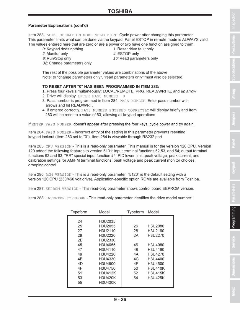
TOSHIBA
9 - 26
Parameter Explanations (cont'd)
Item 283, PANEL OPERATION MODE SELECTION - Cycle power after changing this parameter.This parameter limits what can be done via the keypad. Panel ESTOP in remote mode is ALWAYS valid.The values entered here that are zero or are a power of two have one function assigned to them:
0: Keypad does nothing 1: Reset drive fault only2: Monitor only 4: ESTOP only8: Run/Stop only 16: Read parameters only32: Change parameters only
The rest of the possible parameter values are combinations of the above.Note: to "change parameters only", "read parameters only" must also be selected.
TO RESET AFTER "0" HAS BEEN PROGRAMMED IN ITEM 283:1. Press four keys simultaneously: LOCAL/REMOTE, PRG, READ/WRITE, and up arrow2. Drive will display ENTER PASS NUMBER 03. Pass number is programmed in Item 284, PASS NUMBER. Enter pass number with arrows and hit READ/WRT.4. If entered correctly, PASS NUMBER ENTERED CORRECTLY will display briefly and Item 283 will be reset to a value of 63, allowing all keypad operations.
If ENTER PASS NUMBER doesn't appear after pressing the four keys, cycle power and try again.
Spec
ifica
tions
Prec
autio
nsW
iring
Jum
pers
Pane
lKe
ypad
Para
met
ers
Prog
ram
min
gSe
rvic
eD
imen
sion
sIn
dex
Insp
ectio
n
Item 284, PASS NUMBER - Incorrect entry of the setting in this parameter prevents resettingkeypad lockout (Item 283 set to "0"). Item 284 is viewable through RS232 port.
Item 285, CPU VERSION - This is a read-only parameter. This manual is for the version 120 CPU. Version120 added the following features to version 5101: input terminal functions 52,53, and 54; output terminalfunctions 62 and 63; "RR" special input function #4; PID lower limit, peak voltage, peak current, andcalibration settings for AM/FM terminal functions; peak voltage and peak current monitor choices;drooping control.
Item 286, ROM VERSION - This is a read-only parameter. "5120" is the default setting with aversion 120 CPU (230/460 volt drive). Application-specific option ROMs are available from Toshiba.
Item 287, EEPROM VERSION - This read-only parameter shows control board EEPROM version.
Item 288, INVERTER TYPEFORM - This read-only parameter identifies the drive model number:
Typeform Model Typeform Model
24 H3U203525 H3U2055 26 H3U208027 H3U2110 28 H3U216029 H3U2220 2A H3U22702B H3U233045 H3U4055 46 H3U408047 H3U4110 48 H3U416049 H3U4220 4A H3U42704B H3U4330 4C H3U44004D H3U4500 4E H3U46004F H3U4750 50 H3U410K51 H3U412K 52 H3U415K53 H3U420K 54 H3U425K55 H3U430K

TOSHIBA
9 - 27
Parameter Explanations (cont'd)
Items 289-292, STATUS MONITOR #<1,2,3,and 4> SELECT - Pressing MON button displays the drive'smonitor mode. See Item 296 to display currents in amps or percent. See Item 297 to display voltages involts or percent. The drive operation variable displayed in four of the monitor mode's screens areselectable:
1: Post-compensation output frequency may be higher than frequency command (drive overspeeds to compensate for slip in vector control).2: Frequency command. Not affected by stopping or accel/decel. Default for STATUS MONITOR #1 DISPLAY SELECT3: Output current. (output amps)2 =(torque amps)2+(excitation amps)2
Default for STATUS MONITOR #2 DISPLAY SELECT4: Input voltage (calculated from DC bus voltage). If displayed in percent, note that 230 V drives consider 200 V to be 100% input and 460 V drives consider 400 V to be 100% input. Default for STATUS MONITOR #3 DISPLAY SELECT5: Output voltage. If displayed in percent, note that 230 V drives consider 200 V to be 100% output and 460 V drives consider 400 V to be 100% output. Default for STATUS MONITOR #4 DISPLAY SELECT6: Torque current. (output current)2 = (torque current)2 + (excitation current)2
7: Excitation current. (output current)2 = (torque current)2 + (excitation current)2
8: PID feedback value. This is the frequency represented by the feedback signal9: Motor overload ratio. Example: H3 is rated for 150% FLA for 2 minutes. If drive runs at 150% for one minute, this output will be 50%. Drive trips when ration hits 100%.10: Inverter overload ratio. See example for selection 9 above.11: Dynamic braking resistor overload ratio. See example for selection 9 above.12: Input power13: Output power14: "RR" terminal input value (the variable displayed here varies with the setting of Item 79, RR INPUT SPECIAL FUNCTION SELECT ).15: Peak output current. Peak is reset by cycling power, initiating a run, or resetting drive.16: Peak input voltage. Peak is reset by cycling power, initiating run, or resetting drive. Calculated from DC bus. If displayed in percent, note that 230 V drives consider 200 V input to be 100% and that 460 drives consider 400 V input to be 100%.
Item 293, FREQUENCY UNITS SCALE FACTOR - Drive's frequency output display can be scaled byputting a non-zero value here. Drive's display will still read OUTPUT FREQUENCY, but HZ will no longer bevisible.
Item 294, FREQUENCY DISPLAY RESOLUTION - Use this parameter to select the number of decimalpoints for keypad's output frequency display.
Item 295, ACC/DEC TIME UNITS SELECTION - Affects Items 10,11,21, and 22 (sets resolution ofaccel/decel times).
Item 296, CURRENT UNITS SELECTION - With this parameter set to "1", drive displays currents in amps.
Item 297, VOLTAGE UNITS SELECTION - With this parameter set to "0", the voltages displayed in themonitor are in percent.
Item 298, BLIND FUNCTION SELECTION - Page 8-31 contains the parameters that unblind the H3'sprogramming groups. Item 298 must be set to "1" before Items 299-315 can be read or changed.
Item 299, FUNDAMENTAL PARAMS #2 BLIND - This parameter must be set to "1" before any of theparameters on page 8-2 can be read or changed. Putting a "1" here adds GROUP: FUNDAMENTALPARAMETERS #1 to the group list (accessed via the PRG button).

TOSHIBA
Parameter Explanations (cont'd)
Item 300, PANEL CONTROL PARAMS BLIND - This parameter must be set to "1" before any of theparameters on page 8-3 can be read or changed. Putting a "1" here adds GROUP:PANEL CONTROLPARAMETERS to the visible group list (accessed via the PRG button).
Item 301, TERMINAL SELECTION PARAMS BLIND - This parameter must be set to "1" before any of theparameters on pages 8-5 through 8-7 can be read or changed. Putting a "1" here adds GROUP:TERMINALSELECTION PARAMETERS to the visible group list (accessed via the PRG button).
Item 302, SPECIAL CONTROL PARAMS BLIND - This parameter must be set to "1" before any of theparameters on page 8-3 can be read or changed. Putting a "1" here adds GROUP:SPECIAL CONTROLPARAMETERS to the visible group list (accessed via the PRG button).
Item 303, FREQUENCY SETTING PARAMS BLIND - This parameter must be set to "1" before any of theparameters on pages 8-8 through 8-12 can be read or changed. Putting a "1" here addsGROUP:FREQUEMCY SETTING PARAMETERS to the visible group list (accessed via the PRG button).
Item 304, PROTECTION FUNCTION PARAMS BLIND - This parameter must be set to "1" before any ofthe parameters on pages 8-13 through 8-15 can be read or changed. Putting a "1" here addsGROUP:PROTECTION FUNCTION PARAMETERS to the visible group list (accessed via the PRG button).
Item 305, PATTERN RUN CONTROL PARAMS BLIND - This parameter must be set to "1" before any ofthe parameters on pages 8-16 through 8-21 can be read or changed. Putting a "1" here addsGROUP:PATTERN RUN CONTROL PARAMETERS to the visible group list (accessed via the PRG button).
Item 306, FEEDBACK CONTROL PARAMS BLIND - This parameter must be set to "1" before any of theparameters on pages 8-22 through 8-23 can be read or changed. Putting a "1" here addsGROUP:FEEDBACK CONTROL PARAMETERS to the visible group list (accessed via the PRG button).
Item 307, COMMUNICATION PARAMETERS BLIND - This parameter must be set to "1" before any of theparameters on pages 8-24 through 8-25 can be read or changed. Putting a "1" here addsGROUP:COMMUNICATION PARAMENTERS to the visible group list (accessed via the PRG button).
Item 308, INDUSTRIAL APPL: PUMP PARAMS BLIND - Putting a "1" here adds GROUP:INDUSTRIALAPPLICATION - PUMP to the visible group list (accessed via the PRG button). This group containsparameters from other groups which may be useful when programming the drive for a pump application.The settings of these parameters are still set at factory default. Contact your Toshiba distributor for theIndustrial Application Manual for more information on the pump group.
Item 309, INDUSTRIAL APPL: FAN PARAMS BLIND - Putting a "1" here addsGROUP:INDUSTRIAL APPLICATION - FAN to the visible group list (accessed via the PRG button). Thisgroup contains parameters from other groups which may be useful when programming the drive for a fanapplication. The settings of these parameters are still set at factory default. Contact your Toshibadistributor for the Industrial Application Manual for more information on the fan application group.
Item 310, INDUSTRIAL APPL: CONVEYOR BLIND - Putting a "1" here addsGROUP:INDUSTRIAL APPL - CONVEYOR to the visible group list (accessed via the PRG button). Thisgroup contains parameters from other groups which may be useful when programming the drive for aconveyor application. The settings of these parameters are still set at factory default. Contact your Toshibadistributor for the Industrial Application Manual for more information on the conveyor application group.
Item 311, INDUSTRIAL APPL: HOIST BLIND - Putting a "1" here addsGROUP:INDUSTRIAL APPLICATION - HOIST to the visible group list (accessed via the PRG button).This group contains parameters from other groups which may be useful when programming the drive for ahoist application. The settings of these parameters are still set at factory default. Contact your Toshibadistributor for the Industrial Application Manual for more information on the hoist application group.
9 - 28
Spec
ifica
tions
Prec
autio
nsW
iring
Jum
pers
Pane
lKe
ypad
Para
met
ers
Prog
ram
min
gSe
rvic
eD
imen
sion
sIn
dex
Insp
ectio
n

TOSHIBA
9 - 29
Parameter Explanations (cont'd)
Item 312, INDUSTRIAL APPL: TEXTILES BLIND - Putting a "1" here addsGROUP:INDUSTRIAL APPL - TEXTILES to the visible group list (accessed via the PRG button). Thisgroup contains parameters from other groups which may be useful when programming the drive for atextile application. The settings of these parameters are still set at factory default. Contact your Toshibadistributor for the Industrial Application Manual for more information on the textile application group.
Item 313, INDUSTRIAL APPL: TOOLS BLIND - Putting a "1" here addsGROUP:INDUSTRIAL APPL - MACHINE TOOLS to the visible group list (accessed via the PRG button).This group contains parameters from other groups which may be useful when programming the drive for amachine tool application. The settings of these parameters are still set at factory default. Contact yourToshiba distributor for the Industrial Application Manual for more information on the machine tool applica-tion group.
Item 314, AM/FM ADJUSTMENT PARAMS BLIND - This parameter must be set to "1" before any of theparameters on page 8-27 can be read or changed. Putting a "1" here adds GROUP:AM/FM ADJUSTMENTPARAMS to the visible group list (accessed via the PRG button).
Item 315, MOTOR PARAMETERS BLIND - This parameter must be set to "1" before any of the parameterson page 8-31 can be read or changed. Putting a "1" here adds GROUP:MOTOR PARAMETERS to the visiblegroup list (accessed via the PRG button).
Item 316, NUMBER OF MOTOR POLES - Enter number of motor poles.
Item 317, MOTOR RATED CAPACITY - Enter motor KW. 1 HP = 0.746 KW.
Item 318, MOTOR TYPE - This parameter describes the motor as follows:0: Toshiba/Houston EQP3 (premium efficiency)1: Toshiba/Houston High Efficient (standard efficiency)2: Non-Toshiba/Houston motor
Item 319, MOTOR RATED VOLTAGE - Enter motor nameplate voltage.
Item 320, MOTOR RATED FREQUENCY - Enter motor nameplate frequency.
Item 321, MOTOR RATED RPM - Enter motor nameplate full-load RPM.
Item 322, AUTO-TUNING ENABLE - To auto-tune a motor, enter a "1" here. When the next run isinitiated, the drive performs an autotuning which lasts a fraction of a second. Item 322 is thenreset to "0".
Item 323, LOAD MOMENT OF INERTIA - Estimate the load's inertia as folows:0: Small1: Medium2: Large3: Very largeIn the event of an AUTO-TUNING ERROR, try a different inertia level.

TOSHIBA
9 - 30
Programming Examples
Preset Speed ExampleThe following example uses "S1" and "S2" terminals to access three preset speeds of 11.0 Hz(close "S1"-"CC"), 55.0 Hz (close "S2"-"CC"), and 33.7 Hz (close "S1" and "S2" to "CC"). "F"-"CC"and "ST"-"CC" must be made on the drive's terminal strip. This example assumes drive isdefaulted to factory settings prior to when the following programming is done.
Group Parameter Value UTILITY PARAMETERS BLIND FUNCTION SELECTION 1 UTILITY PARAMETERS FREQUENCY SETTING PARAMETERS BLIND 1 FREQUENCY SETTING PARAMETERS PRESET SPEED SELECTION 3 FREQUENCY SETTING PARAMETERS PRESET SPEED MODE ACTIVATION 0 FREQUENCY SETTING PARAMETERS PRESET SPEED #1 FREQUENCY 11 FREQUENCY SETTING PARAMETERS PRESET SPEED #1 OPERATING MODE 0 FREQUENCY SETTING PARAMETERS PRESET SPEED #2 FREQUENCY 55 FREQUENCY SETTING PARAMETERS PRESET SPEED #2 OPERATING MODE 0 FREQUENCY SETTING PARAMETERS PRESET SPEED #3 FREQUENCY 33.7 FREQUENCY SETTING PARAMETERS PRESET SPEED #3 OPERATING MODE 0
LOCAL LED must be off to run from terminal strip. See page 9-15 for parameter explanations.
Trim Pot ExampleThis example uses the "RX" terminal to trim a reference (i.e. a 4-20 mA input) +7/-5 Hz.
Group Parameter Value UTILITY PARAMETERS BLIND FUNCTION SELECTION 1 UTILITY PARAMETERS FEEDBACK CONTROL PARAMETERS BLIND 1 UTILITY PARAMETERS FREQUENCY SETTING PARAMETERS BLIND 1 FEEDBACK PARAMETERS OVERRIDE CONTROL SELECTION 3 FREQUENCY SETTING PARAMETERS RX TERMINAL STANDARD OR ADJUSTABLE 1 FREQUENCY SETTING PARAMETERS RX REFERENCE SETTING POINT #1 0 % FREQUENCY SETTING PARAMETERS RX REFERENCE POINT #1 FREQUENCY 7 HZ FREQUENCY SETTING PARAMETERS RX REFERENCE SETTING POINT #2 100 % FREQUENCY SETTING PARAMETERS RX REFERENCE POINT #2 FREQUENCY -5 HZ
Motor Operated PotThe following programming allows a drive to emulate motor operated pot control. Momentarilyshorting "S1"-"CC" increases frequency reference. Momentarily shorting "S2"-"CC" decreasesfrequency reference. Momentarily shorting "S3"-"CC" erases frequency reference. "F"-"CC" and"ST"-"CC" must be made on the drive's terminal strip. This example assumes drive is defaulted tofactory settings prior to the following programming is done.
Group Parameter Value UTILITY PARAMETERS BLIND FUNCTION SELECTION 1 UTILITY PARAMETERS TERMINAL SELECTION PARAMETERS BLIND 1 UTILITY PARAMETERS FREQUENCY SETTING PARAMETERS BLIND 1 TERMINAL SELECTION PARAMETERS INPUT TERMINAL SELECTION 1 TERMINAL SELECTION PARAMETERS "S1" INPUT TERMINAL FUNCTION 34 TERMINAL SELECTION PARAMETERS "S2" INPUT TERMINAL FUNCTION 35 TERMINAL SELECTION PARAMETERS "S3" INPUT TERMINAL FUNCTION 36 FREQUENCY SETTING PARAMETERS FREQUENCY PRIORITY SELECTION #1 5
The LOCAL LED must be off to run from terminal strip. See pages 9-7 and 9-13 for parameterexplanations.
Spec
ifica
tions
Prec
autio
nsW
iring
Jum
pers
Pane
lKe
ypad
Para
met
ers
Prog
ram
min
gSe
rvic
eD
imen
sion
sIn
dex
Insp
ectio
n

TOSHIBA
9 - 31
Programming Examples (cont'd)
True Torque Control Programming
The drive can be programmed to utilize True Torque Control (TTC), the benefits of which are slipcompensation and high torque at low speed. In volts per hertz control (or across the line ), a typical ACinduction motor will lose 3-5% of its RPM as it goes from no load to full load; when operated in TTC mode,a motor will slow a maximum of 0.5% of base RPM as it is loaded. Motors operated on volts per hertzdrives cannot develop their rated torque when operated at low frequencies; the same motor operated inTTC mode can typically develop 200% of its rated torque at one Hz.
The drive divides the motor current it is providing into two components that are ninety degrees out ofphase: the excitation current and the torque current. Excitation current is the part of the total current thatdevelops the magnetic field in the motor's core. The torque current is the current that does the usefulwork. According to the Pythagorean theorem, (total current)2 = (torque current)2 + (excitation current)2.The drive calculates and controls these currents based on motor models to optimize motor performance.
If a Toshiba/Houston motor is used, the drive will use an on-board motor model. If a generic motor isused, the drive can be programmed to auto-tune. During auto tuning, the drive derives a motor model byapplying a voltage to the motor and analyzing the resulting decay.
These parameters must be adjusted to use TTC with a TOSHIBA/HOUSTON motor.
Group Parameter Value UTILITY PARAMETERS BLIND FUNCTION SELECTION 1 UTILITY PARAMETERS MOTOR PARAMETERS BLIND 1 FUNDAMENTAL PARAMETERS #1 VOLTS PER HERTZ PATTERN 5 MOTOR PARAMETERS NUMBER OF MOTOR POLES * MOTOR PARAMETERS MOTOR RATED CAPACITY * MOTOR PARAMETERS MOTOR TYPE ** MOTOR PARAMETERS LOAD MOMENT OF INERTIA ***
The following parameters must be adjusted to use TTC for a GENERIC motor.
Group Parameter Value UTILITY PARAMETERS BLIND FUNCTION SELECTION 1 UTILITY PARAMETERS MOTOR PARAMETERS BLIND 1 FUNDAMENTAL PARAMETERS #1 VOLTS PER HERTZ PATTERN 5 MOTOR PARAMETERS NUMBER OF MOTOR POLES * MOTOR PARAMETERS MOTOR RATED CAPACITY * MOTOR PARAMETERS MOTOR TYPE 2 MOTOR PARAMETERS MOTOR RATED VOLTAGE * MOTOR PARAMETERS MOTOR RATED FREQUENCY * MOTOR PARAMETERS MOTOR RATED RPM * MOTOR PARAMETERS AUTO-TUNING ENABLE 1**** MOTOR PARAMETERS LOAD MOMENT OF INERTIA ***
* Enter appropriate value from motor's nameplate. KW = 0.746 X HP.** Enter "0" for an EQPIII or "1" for a high efficiency motor.*** If the drive displays AUTO TUNE ERROR, try a different inertia setting.**** The drive will auto tune the next time a run is initiated. This parameter is then reset to "0" by the drive`.

TOSHIBA
10 - 1
SECTION 10: ServiceRequesting Service
When requesting service, report the contents of the following problem information sheet.
Problem Information Sheet
ItemCustomer's name
Refer to Person in chargeAddressTelephone No.
Drive Model No.spec. Serial No.
Test No.Delivery dateTime in serviceDate when problem arose
UseMotor rating Poles, Hp, V, Hz.
Made by Toshiba? Made by another company?New? Number of units?Alternate? Continuous?
Status of Indoor? Outdoor? Temperature range?Use Ambient Humidity:
condition Dust composition and size:Presence of salt and extent of corrosion from it:Vibrations, in micrometers:Presence of corrosive gas:Availability of air conditioning:Number of phases:Voltage between L1 phase and L2 phase:
Power Voltage between L2 phase and L3 phase:source Voltage between L3 phase and L1 phase:
Number of Hz:Problem occurred hours after motor had been started. Motor hasbeen stopped for hours.
Phenome- State of Problem occurred during periodic inspection?non motor when Problem occurred when motor was started?
problem was Problem occurred during acceleration?found Problem occurred during deceleration?
Problem occurred while motor was not running?Frequency First time? Problem occurred times in the past.of problem Problem occurs sometimes?
Problem occurs every time motor is operated?When did problem first occur?
Troubleindicator
Detailed description of problem:
Temporary diagnosis and corrective action:
Date defective product shipped: To:Deadline for repairs:
Indicate LCD Screen Message:
Only qualified personnel should be allowed to service this equipment.
Spec
ifica
tions
Prec
autio
nsW
iring
Jum
pers
Pane
lKe
ypad
Para
met
ers
Prog
ram
min
gSe
rvic
eD
imen
sion
sIn
dex
Insp
ectio
n

TOSHIBA
10 - 2
Parts Service LifeIn order to obtain the best performance and to get the maximum service life from the drive itis necessary to perform timely maintenance repairs on some parts of the system even thoughthe equipment may still be functioning with no apparent problems.
Use the following service life chart as a guide for major part periodic replacement when theequipment is used in a standard installation service environment.
Service Life Replacement Chart
Part Name Service Life Remarks
Large capacity 5 Years To be electrified semiannually inelectrolytic capacitor case of long term disuse.
Cooling Fan 26000 Hours Internal fans
Contact relays 500,000 operations
Connectors 100 operations Replace pin in case of failure.

TOSHIBA
10 - 3
Troubleshooting
If the drive faults, the following questions may help to pinpoint the reason for the trip:1. Does the drive trip when accelerating, running, decelerating, or when not running ?2. Can the drive make it to commanded frequency ?3. Does the drive trip without the motor attached ?4. Does drive trip with an unloaded motor ?
Drive data at the time of trip is saved in the monitor and can be read until the trip is cleared. Beforeclearing the trip, make a note of this information. A history of past faults can be viewed by pressing theMON button and then the down arrow until PAST FAULTs are displayed. Some trips are the result ofimproper programming; resetting the drive to factory settings may be a solution (see Item 280, STANDARDSETTING MODE SELECTION).
How to clear a fault1. Cycling power2. Pressing the STOP/CLEAR button twice3. Closing "RES"-"CC" on the terminal strip (with default drive programming).
If Item 172, FAULT TRIP EEPROM SAVE ENABLE is set to "1", the drive will power up with the faultdisplay, but the fault monitor and any fault contacts will be reset. On OVERLOAD trips, reset can occur onlyafter a cooling time; see explanation for Item 161, OVERLOAD SELECTION. No cooling time for reset isrequired when power is cycled.
RETRYSee Items 153, NUMBER OF RETRY ATTEMPTS and Item 154, TIME BETWEEN RETRY ATTEMPTS toprogram drive to automatically attempt to reset faults. Drive will display ATTEMPTING TO RESTARTduring retries. See page 9-12 for a list of faults to retry. Retry will not function if Item 172, FAULT TRIPEEPROM SAVE ENABLE is set to "1" (on).
The keypad, control board (with phone jack), and terminal strip board are common to all driveratings. If a board or keypad is suspect, exchange with a known good board/keypad to verify.
Drive Fault Displays and Explanations
OVERCURRENT (ACCEL) or DC OVERCURRENT (ACC)Cause: Drive current exceeded 215% of its rated FLA (190% above 100 HP).Comments: Check for phase-phase short. ACCELERATION TIME may be too small. VOLTAGEBOOST may be too high. Is motor/machine jammed? Is mechanical brake engaged while drive isrunning? If drive is starting into a rotating motor, see Item 157, AUTO-RESTART (MOTOR SPEEDSEARCH). If there is a contactor between motor and drive, wire so that contactor changes stateonly when drive is outputting 0.0 Hz. Drive will automatically adjust accel time with Item 12,ACC/DEC PATTERN #1 SELECTION set to "1".
OVERCURRENT (DECEL) or DC OVERCURRENT (DEC)Cause: Drive current exceeded 215% of its rated FLA (190% above 100 HP).Comments: Check for phase-phase short. DECELERATION TIME may be too small. Is motor/machine jammed? Is mechanical brake engaged while drive is running? Adding appropriatebraking resistor across "PA" and "PB" terminals may solve problem (see page 9-16). Drive willautomatically adjust decel time with Item 12, ACC/DEC PATTERN #1 SELECTION set to "1".
OVERCURRENT (RUN) or DC OVERCURRENT (RUN)Cause: Drive current exceeded 215% of its rated FLA.Comments: Check for phase-phase short. Is motor/machine jammed? Is mechanical brakeengaged while drive is running? Adding appropriate dynamic braking resistor across "PA" and"PB" terminals may solve problem (see page 9-16). If there are severe load fluctuations, addingmechanical dampening or an output line reactor may help to electrically dampen.
Spec
ifica
tions
Prec
autio
nsW
iring
Jum
pers
Pane
lKe
ypad
Para
met
ers
Prog
ram
min
gSe
rvic
eD
imen
sion
sIn
dex
Insp
ectio
n

TOSHIBA
10 - 4
Drive Fault Displays and Explanations (cont'd)
U-PHASE SHORT-CIRCUIT or V PHASE SHORT-CIRCUIT or W PHASE SHORT-CIRCUITCause: Drive detected short-circuit in transistor.Comments: Replace transistor. Contact your Toshiba distributor for authorized repair.
LOAD-END OVERCURRENTCause: Drive detected short-circuit on output.Comments: Check for phase-phase short. Meg motor/leads with leads disconnected fromdrive . Remove any power factor correction caps on motor. See Item 169, OUTPUT SHORT-CIRCUIT DETECTION SELECT .
OVERVOLTAGE (ACCEL) or OVERVOLTAGE (RUN)Cause: Bus exceeded 393 VDC (230 volt drive),or 787 VDC (460 volt drive).Comments: Incoming AC may have gone high or spiked (verify with Item 289,290, 291, or 292set to "16"); a line reactor or a lower tap on transformer may help. Motor may be mechanicallyforced to run faster than drive is commanding; install appropriate dynamic braking resistor (seepage 9-16). On eccentric cyclic loads like presses or pump jacks, contact your Toshiba distributorfor special programming instructions that may make a DBR unnecessary.
OVERVOLTAGE (DEC)Cause: Bus exceeded 393 VDC (230 volt drive),or 787 VDC (460 volt drive).Comments: Incoming AC may have gone high or spiked (verify with Item 289 set to "16"); a linereactor or a lower tap on transformer may help. Item 11, DECELERATION TIME #1 may be tooshort. Drive will automatically change decel time with Item 12, ACC/DEC PATTERN ADJUSTLOW set to "1". Make sure Item 145, OVERVOLTAGE STALL PROTECTION is set to "0". Motormay be mechanically forced to run faster than drive is commanding (due to large load inertiasmechanical couplings); install appropriate dynamic braking resistor (see page 9-16). On eccentriccyclic loads like presses or pump jacks, contact your Toshiba distributor for special programminginstructions that may make a DBR unnecessary.
INVERTER OVERLOADCause: Drive exceeded 110% of its rated current for too long of a time.Comments: This trip indicates that the drive output exceeded its rated current for specificamounts of time. For example, 100 HP and smaller drives can output 150% of their rated currentfor 120 seconds, 130% for 240 seconds, 170% for 3.5 seconds, and 185% for 0.5 seconds.If using DC Injection, Item 147, DC INJECTION CURRENT MAGNITUDE or Item 148 DCINJECTION TIME they may be too large. If Item 42, PWM CARRIER FREQUENCY is greater than8 KHz, try carrier frequencies less than 8 KHz. Programming Item 161, OVERLOAD SELECTIONto "1" or "3" (soft stall on) makes the drive reduce output frequency/voltage to shed load (worksbest on variable torque applications). Motor or load bearings may have seized. Enabling TrueTorque Control (see page 9-31) may reduce drive's current output and solve the problem. Makesure that drive is seeing voltage on all three of its input phases. Drive may be undersized.
MOTOR OVERLOADCause: Motor is in danger of overheating because it drew too much current for too long of a time,as determined by the drive.Comments: See page 9-17. Check Items 158, 159, 160, and 161. If trip occurred at a lowfrequency, the setting of Item 159, OVERLOAD REDUCTION START FREQUENCY is probablycritical. Motor overload protection can be turned off by placing a "2" or "3" in Item 161. Checkvalue in Item 160, MOTOR 150% OVERLOAD TIME LIMIT .

TOSHIBA
10 - 5
Drive Fault Displays and Explanations (cont'd)
DBR OVERCURRENTCause: IGBT7 (dynamic braking transistor) is damagedComments: Check ohm value connected to "PA" and "PB" terminals (see page 9-16 for minimumohm values). If using multiple resistors, make sure parallel-series combination is wired correctly.Check IGBT7. Check DC bus fuse for continuity; if open, check output transistors. Consult yourToshiba distributor for authorized service.
DBR OVERLOADCause: Dy namic braking resistor is in danger of overheating (as determined by drive).Comments: Check that the values entered into Item 143, BRAKING RESISTOR VALUE and Item144, BRAKING RESISTOR POWER RATING are correct.
OVERHEATCause: Drive's heatsink exceeded 90o C.Comments: Check drive's muffin fans (if any). Clear heatsinks of anything blocking airflow.The enclosure that the drive is installed in may be too small or there may be to many heat sourcesin the same enclosure. Drive may not have been properly sized for operating altitude. Thermistoron heatsink may be bad.
EMERGENCY OFFCause: Drive received one of the following ESTOP commands:1. Drive was receiving STOP/START command via terminal strip when STOP button on keypad was pressed.2. One of the drive's input terminal's function is set to "10" (see Items 44-55 and page 9-9), and terminal is being opened/closed to command ESTOP.
EEPROM WRITE FAILURE or EEPROM READ FAILURECause: EEPROM was unable to read/write to peripherals.Comments: Check for miswiring that may be causing noise (such as "CC" connected to ground,an external 10 volt source connected to "PP" etc.) Control board may need to be replaced (partnumber 45996). See picture of board on page 5-2.
RAM ERROR or ROM ERRORComments: Check for miswiring that may be causing noise (such as "CC" connected to ground,an external 10 volt source connected to "PP" etc.). Replace control board (part number 45996).See picture of board on page 5-2.
OPTION ROM ERRORComments: Check for miswiring that may be causing noise (such as "CC" connected to ground,an external 10 volt source connected to "PP" etc.). If drive is energized with option ROM installedand is later energized without option ROM installed, this fault will appear. Reset in normal fashion.
CPU ERRORComments: If option ROM or option board is installed or removed when drive is powered, thisfault will appear. Reset like any fault. Check for miswiring that may be causing noise (such as"CC" connected to ground, an external 10 volt source connected to "PP" etc.). If the CPU is trulydamaged, the fault will not reset and replacement of the control board (part number 45996) isnecessary. See picture of control board on page 5-2.
COMMUNICATION ERRORCause: RS232 or RS485 timer did not respondComments: Check wiring to RS232 or RS485 ports. Check setting of Item 264,COMMUNICATION SELECTION (should be "1" for RS485). Check jumpers J1, J2, and J3 onRS485 option board (see RS485 Communications Option Manual). Cable may be broken.
Spec
ifica
tions
Prec
autio
nsW
iring
Jum
pers
Pane
lKe
ypad
Para
met
ers
Prog
ram
min
gSe
rvic
eDi
men
sion
sIn
dex
Insp
ectio
n

TOSHIBA
10 - 6
Drive Fault Displays and Explanations (cont'd)
OPTION PCB ERRORComments: If drive is energized with an option board installed and is later energized without theboard installed, this fault will appear. Check connectors between control board and option board.Check settings of Item 80, FREQUENCY PRIORITY SELECTION #1, Item 81, FREQUENCYPRIORITY SELECTION #2 , and Item 264, COMMUNICATION SELECTION. Use stand-offs tosecure board.
LOW CURRENT TRIPCause: The drive's output current went below the current value entered in Item 167, LOWCURRENT DETECT LEVEL for at least the amount of time entered in Item 168, LOWCURRENT DETECTION TIME.
UNDERVOLTAGE TRIPCause: The drive's DC bus voltage went below 217 VDC (230 V G3), 413 VDC (460 V G3), or594 VDC (600 V G3) for at least the time entered in Item 165, UNDERVOLTAGE DETECT TIME.Comments: Item 164, UNDERVOLTAGE TRIP SELECTION turns the ability to undervoltage tripon/off. On G3 models 2080-2110 and 4080-4270, turning on Item 155, REGENERATION POWERRIDE-THROUGH and adjusting Item 156, REGENERATION RIDE-THROUGH TIME may keep busup during brown out if there is sufficient regen energy from the load.
OVERTORQUE TRIPCause: The drive's torque current went above the current value programmed in Item 171,OVERTORQUE TRIP LEVEL. The G3 can be programmed to torque current limit; contact yourToshiba distributor and request the torque limit application guideline.
EARTH FAULT (SOFT) or EARTH FAULT (HARD)Cause: Drive detected some current to ground. Depending on rating, drive senses ground fault viaZCT (hard fault) or HCT (soft fault).Comments: With leads disconnected from drive, meg motor and leads. Look for any moisture thatmay provide current path to ground. Make sure that control wiring is separated from power wiring.Adding noise supressors on coils of starters on same line as drive may snub noise picked up byZCT. RF/EMI filter may help remove noise generated by SCR rectifiers in the vicinity. Make suredrive chassis and motor are grounded.
AUTO-TUNING ERRORCause: Motor's physical characteristics are not within the window of allowable values for modeling.Comments: Try a different inertia setting in Item 323, LOAD MOMENT OF INERTIA. Motor mustbe at rest to perform auto-tuning. Motor must be one HP size within the drive's HP size.Auto-tuning is best done with motor at full-load temperature (if temperature is very cold, auto-tuneerror may appear).
GATE ARRAY FAULTComments: Replace control board.
CURRENT DETECT ERRORComments: Occurs when drive is stopped but CPU detects current flowing. This fault could becaused by plugging in RS232 cable with drive powered (resulting in damage to control board).Adding a RF/EMI filter may remove noise spikes from nearby SCR rectifiers. If the control boardis damaged, the drive must be serviced.
INV TYPEFORM ERRORCause: Control board is not configured to drive's rating.Comments: Enter "7" into Item 280, STANDARD SETTING MODE SELECTION.

TOSHIBA
10 - 7
Drive Warning Displays and Explanations
DC BUS UNDERVOLTAGECause: The drive's DC bus voltage went below approximately 200 VDC (230 volt drive), or395 VDC (460 volt drive), for at least the time entered in Item 165, UNDERVOLTAGE DETECTTIME.Comments: Item 164, UNDERVOLTAGE TRIP SELECTION turns the ability to undervoltage tripon/off.
CONTROL POWER LOWControl Power low warning voltage levels are sensed on DC bus and are set slightly less than DCBUS UNDERVOLTAGE levels.
OVERLOADA flashing overcurrent display means that the drive is outputting more than 110% of its ratedcurrent. If Item 161, OVERLOAD SELECTION is set to "1" or "3" (soft stall on), the drive's outputfrequency will automatically decrease in an effort to reduce current. See suggestions forremedying an inverter overload trip on page 10-4. Setting one of the monitor's functions (Items289-292) to "10" will give an indication of how close a drive is to tripping.
OVERCURRENTA flashing overcurrent display means that the drive is stalling. (Stall level is set by Item 160,STALL PROTECTION CURRENT LEVEL). The drive's output frequency will automaticallydecrease.
OVERVOLTAGEA flashing overvoltage display means that the drive's DC bus has exceeded 360 VDC (230 voltdrive), or 720 VDC (460 volt drive).
OVERHEATA flashing overheat display means that the drive's heat sink temperature has exceeded 84oC.Display dissappears when heatsink temperature reaches 80oC.
COMMA flashing comm display means that the drive has momentarily lost communications. Display willclear when follower receives valid reference. Cycling power or reinitializing drive will clear warning.
Wiri
ngJu
mpe
rsPa
ram
eter
sPa
nel
Serv
ice
Dim
ensi
ons
Inde
xIn
spec
tion
Prec
autio
nsSp
ecifi
catio
nsKe
ypad
Prog
ram
min
g
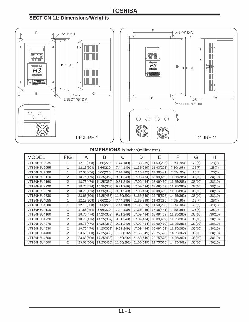
MODEL FIG A B C D E F G HVT130H3U2035 1 12.13(308) 8.66(220) 7.44(189) 11.38(289) 11.63(295) 7.69(195) .28(7) .28(7)VT130H3U2055 1 12.13(308) 8.66(220) 7.44(189) 11.38(289) 11.63(295) 7.69(195) .28(7) .28(7)VT130H3U2080 1 17.88(454) 8.66(220) 7.44(189) 17.13(435) 17.38(441) 7.69(195) .28(7) .28(7)VT130H3U2110 2 18.75(476) 14.25(362) 9.81(249) 17.09(434) 18.09(459) 11.25(286) .38(10) .38(10)VT130H3U2160 2 18.75(476) 14.25(362) 9.81(249) 17.09(434) 18.09(459) 11.25(286) .38(10) .38(10)VT130H3U2220 2 18.75(476) 14.25(362) 9.81(249) 17.09(434) 18.09(459) 11.25(286) .38(10) .38(10)VT130H3U2270 2 18.75(476) 14.25(362) 9.81(249) 17.09(434) 18.09(459) 11.25(286) .38(10) .38(10)VT130H3U2330 2 23.63(600) 17.25(438) 11.50(292) 21.63(549) 22.75(578) 14.25(362) .38(10) .38(10)VT130H3U4055 1 12.13(308) 8.66(220) 7.44(189) 11.38(289) 11.63(295) 7.69(195) .28(7) .28(7)VT130H3U4080 1 12.13(308) 8.66(220) 7.44(189) 11.38(289) 11.63(295) 7.69(195) .28(7) .28(7)VT130H3U4110 1 17.88(454) 8.66(220) 7.44(189) 17.13(435) 17.38(441) 7.69(195) .28(7) .28(7)VT130H3U4160 2 18.75(476) 14.25(362) 9.81(249) 17.09(434) 18.09(459) 11.25(286) .38(10) .38(10)VT130H3U4220 2 18.75(476) 14.25(362) 9.81(249) 17.09(434) 18.09(459) 11.25(286) .38(10) .38(10)VT130H3U4270 2 18.75(476) 14.25(362) 9.81(249) 17.09(434) 18.09(459) 11.25(286) .38(10) .38(10)VT130H3U4330 2 18.75(476) 14.25(362) 9.81(249) 17.09(434) 18.09(459) 11.25(286) .38(10) .38(10)VT130H3U4400 2 23.63(600) 17.25(438) 11.50(292) 21.63(549) 22.75(578) 14.25(362) .38(10) .38(10)VT130H3U4500 2 23.63(600) 17.25(438) 11.50(292) 21.63(549) 22.75(578) 14.25(362) .38(10) .38(10)VT130H3U4600 2 23.63(600) 17.25(438) 11.50(292) 21.63(549) 22.75(578) 14.25(362) .38(10) .38(10)
11 - 1
SECTION 11: Dimensions/WeightsTOSHIBA
FIGURE 1
F 2-"H" DIA.
CB .27
AED
FIGURE 2
AED
F
B C.252-SLOT "G" DIA.
2-"H" DIA.
DIMENSIONS in inches(millimeters)
2-SLOT "G" DIA.
H3H3
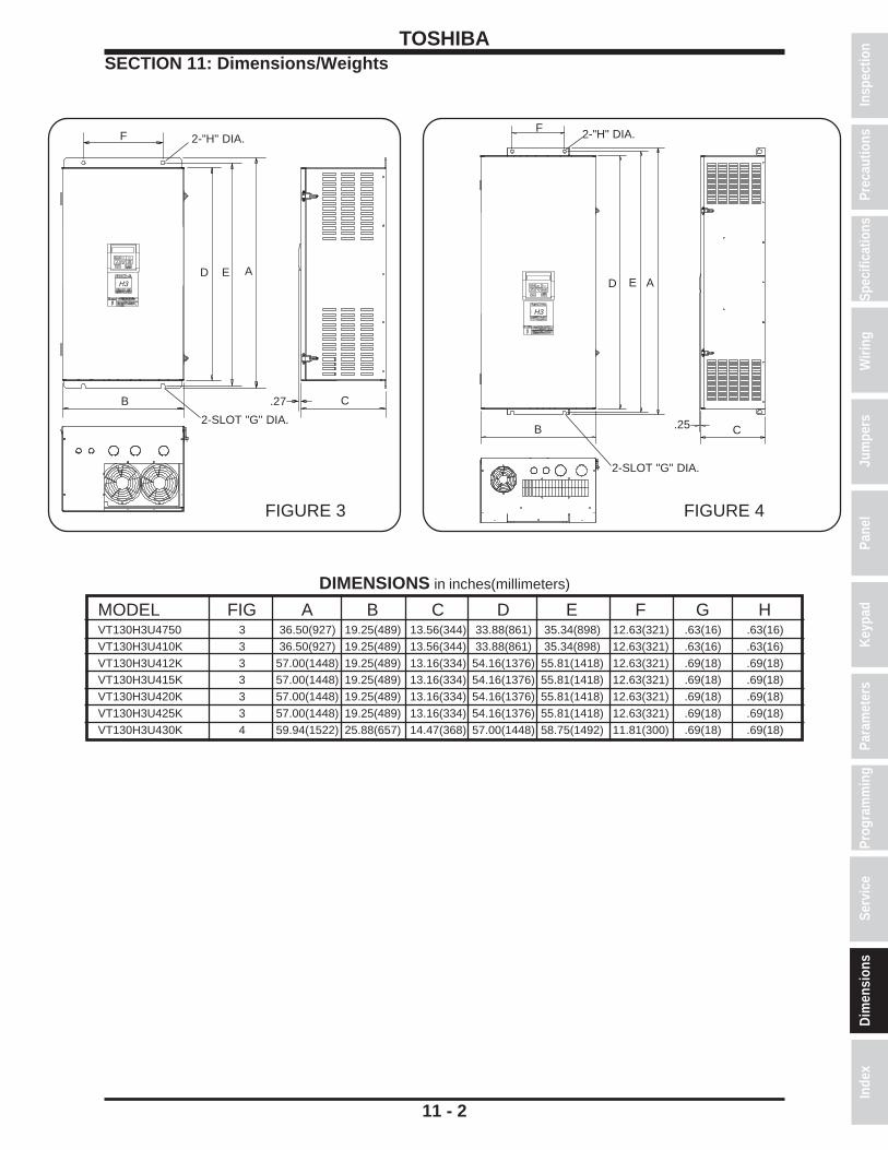
MODEL FIG A B C D E F G HVT130H3U4750 3 36.50(927) 19.25(489) 13.56(344) 33.88(861) 35.34(898) 12.63(321) .63(16) .63(16)VT130H3U410K 3 36.50(927) 19.25(489) 13.56(344) 33.88(861) 35.34(898) 12.63(321) .63(16) .63(16)VT130H3U412K 3 57.00(1448) 19.25(489) 13.16(334) 54.16(1376) 55.81(1418) 12.63(321) .69(18) .69(18)VT130H3U415K 3 57.00(1448) 19.25(489) 13.16(334) 54.16(1376) 55.81(1418) 12.63(321) .69(18) .69(18)VT130H3U420K 3 57.00(1448) 19.25(489) 13.16(334) 54.16(1376) 55.81(1418) 12.63(321) .69(18) .69(18)VT130H3U425K 3 57.00(1448) 19.25(489) 13.16(334) 54.16(1376) 55.81(1418) 12.63(321) .69(18) .69(18)VT130H3U430K 4 59.94(1522) 25.88(657) 14.47(368) 57.00(1448) 58.75(1492) 11.81(300) .69(18) .69(18)
11 - 2
TOSHIBASECTION 11: Dimensions/Weights
Prog
ram
min
gPa
ram
eter
sKe
ypad
Pane
lJu
mpe
rsW
iring
Spec
ifica
tions
Insp
ectio
nSe
rvic
eIn
dex
Dim
ensi
ons
Prec
autio
ns
DIMENSIONS in inches(millimeters)
FIGURE 3
F
FIGURE 4
F
E A
B
2-SLOT "G" DIA.
2-"H" DIA.
.27
D
C
AE
B
2-"H" DIA.
C.25
2-SLOT "G" DIA.
H3
H3
D

TOSHIBA
11 - 3
Shipping Weights
H3 Shipping Weight H3 Shipping WeighModel Pounds Kg Model Pounds Kg2035 17 7.7 4055 23 10.52055 19 8.6 4080 24 10.92080 31 14.1 4110 32 14.52110 51 23.2 4160 55 252160 53 24.1 4220 55 252220 54 24.5 4270 56 25.52270 54 24.5 4330 58 26.42330 98 44.5 4400 103 46.8
4500 106 48.24600 110 504750 210 95.5410K 215 975412K 305 138.3415K 315 142.9420K 336 152.4425K 415 188.2430K 440 199.6

TOSHIBA
11 - 4
H3 OptionsA number of option accessories are available for the H3 series of inverters and can be purchased fromyour authorized Toshiba distributor or representative. If you need assistance finding a source for Toshibaproducts in your area, consult Toshiba at 1-800-231-1412.
Product TOSHIBA P/N
RS232 programming software (free) consult distributor
120 VAC digital input option G3-INP
120 VAC digital input option (extended capability) G3-ACI
RS485 Communication Board (38.4 Kbaud) INV3-COM-C (19.2 Kbaud) INV3-COM-A
Extended Terminal Option Board INV3-COM-D(Offers speed feedback control, 3 additional programmable inputs,1 additional programmable Form C relay, pulse input capability)
RS485 Extended Terminal Option Board INV3-COM-B(Offers same capabilities as INV3-COM-D plus 19.2 K baud RS485communication)
Modbus+* network communication board INV3-MODPLUS
Remote I/O* network communication board INV3-RIO
DeviceNet* network communication board INV3-DEVICENET
BCD/12-bit binary input option board G3-VFSX-4526A
Toshiba F-10 network communication board G3-VF5X-1254A
Toshiba S-20 network communication board G3-VF5X-1255A
Input fuse adapter kit(required to internally mount input fuses in G3U2110-2220 and INV3-FUSE-KITG3U4160-4270 drives). Fuses not included.
Isolated 4-20 mA input/output board consult distributor
Long Lead Filters GCIMLL _ _ _ _ _
RF/EMI Filters 3H _ _ _ DF
* Modbus+ is a trademark of Modicon Inc. Remote I/O is a trademark of Allen Bradley Co. Inc. Device Net is a trademark of Open DeviceNet Vendor Association Inc.
Prog
ram
min
gPa
ram
eter
sKe
ypad
Pane
lJu
mpe
rsW
iring
Spec
ifica
tions
Insp
ectio
nSe
rvic
eD
imen
sion
sPr
ecau
tions
Inde
x

TOSHIBA
11 - 5
4.80"
4.25"
5.19"
5.50">
<
<
>
>
>
><
>
>
>
>
4.20"5.38"
H3 Options (con't)
Product TOSHIBA P/N
Holes are 1/4" diameter.
Option ROM: Traverse Control (for 230/460 volt drives) INV3-ROM-6200
Keypad extender cables 3 foot length SX-CABLE-1M9 foot length SX-CABLE-3M15 foot length SX-CABLE-5M
Kit to secure extender cable to keypad INV3-MKITKit to secure extender cable to G3 INV3-BKPANEL
Dynamic Braking Resitors PBR- _ _ _ _ - _ _
Input Fuses Contact Toshiba distributor
DC Link Reactor INV3-DCL- _ _ _ _
Remote Stations (custom stop/start, metering, etc.) VT-REMOTE- _ _ _
Additional H3 documentation available
RS232 Inverter/PC Communications Software Manual (for the free software)
RS232C Communications Manual (protocol information)
Application Guidelines(programming examples such as dancer control, three-wire start, pattern run, and PID)
Devicenet Communications Option Manual
RS485 Communications Manual (protocol information)
Extended Teminal Block Option Manual
Traverse Option ROM Instruction Manual
Modbus+ Communications Option Manual
Cutout Dimensions for Keypad and Cable Securing Kit (INV3-MKIT)

TOSHIBA
12 - 1
INDEXAAcc/dec #1/#2 switch frequency ................................................................................................ 8-2, 9-5Acc/Dec complete detection bandwidth .................................................................................... 8-6, 9-13Acc/dec pattern #1 selection ...................................................................................................... 8-1, 9-4Acc/dec pattern #2 selection ...................................................................................................... 8-2, 9-5Acc/dec pattern adjust high ....................................................................................................... 8-1, 9-5Acc/dec pattern adjust low ......................................................................................................... 8-1, 9-5Acc/dec selection ............................................................................................................ 8-2, 9-6Acc/dec time units selection .................................................................................................... 8-30, 9-27Acceleration time ................................................................................................................ 9-4Acceleration time #1 ............................................................................................................ 8-1, 9-3Acceleration time #2 ............................................................................................................ 8-2, 9-5Adjustment range (parameters) ............................................................................................. 8-1 thru 8-32After sales service ............................................................................................................... 10-1Alarm setting for cumulative run timer ..................................................................................... 8-15, 9-19AM terminal function selection ................................................................................................. 8-27, 9-25AM/FM terminal adjustment parameters ....................................................................................... 8-27Ammeter adjustment .......................................................................................................... 8-27, 9-25Ampacity ........................................................................................................... 3-1 to 3-3Analog input filter ........................................................................................................... 8-8, 9-14Analog meter adjustment .............................................................................................................. 9-25Auto-restart .......................................................................................................... 8-14, 9-17Auto-tuning enable .......................................................................................................... 8-32, 9-29
BBandwidth Acc/Dec detection ........................................................................................................ 8-6Bandwidth of jump frequency #1 thru #3........................................................................................ 8-4Base frequency #1 ................................................................................................................ 8-1Base frequency #2 ................................................................................................................ 8-2Base frequency voltage select ....................................................................................................... 8-1Basic operation ......................................................................................................... 7-1 thru 7-4Baud rates ............................................................................................................... 8-24Bearing considerations ................................................................................................................ 4-7Bias/Gain adjustments ............................................................................................................... 9-14Binary input selection ................................................................................................................ 8-9Binary reference point frequency ............................................................................................... .... 8-9Binary reference pt. setting ............................................................................................................ 8-9Blind function selection ........................................................................................................... 8-31, 9-2Blind/unblind function parameters ............................................................................................. 8-31, 9-2Braking resistor selection ........................................................................................................ 8-13, 9-16Braking selection (dynamic) ..................................................................................................... 8-13, 9-15
CCapacitors (PF) precautions .......................................................................................................... 2-2Capacity of motor rating ............................................................................................................... 8-32Carrier frequency ................................................................................................................ 8-4Catch spinning motor ............................................................................................................... 9-17CEC requirements ................................................................................................................ 4-6Circuit board (control) ................................................................................................................ 5-3Circuit board (main) ................................................................................................................ 5-1Circuit board (terminal) ................................................................................................................ 5-2Circuit breaker size (MCCB) .......................................................................................................... 4-3
Insp
ectio
nPr
ecau
tions
Spec
ifica
tions
Wiri
ngJu
mpe
rsPa
nel
Keyp
adPa
ram
eter
sPr
ogra
mm
ing
Serv
ice
Dim
ensi
ons
Inde
x

TOSHIBA
12 - 2
INDEX (cont'd)C (con't)Clearances ................................................................................................................ 2-1Coast stop ................................................................................................................ 7-2Codes (regulatory) ................................................................................................................ 2-1Color (cabinet) ................................................................................................................ 3-5Command mode selection ....................................................................................................... 8-28, 9-25Commercial power switching output .............................................................................................. 8-6Communication selection ........................................................................................................ ...... 8-24Communication setting parameters ...................................................................................... 8-24 thru 8-25Confirmation (wiring) ................................................................................................................ 2-3Connection diagrams ........................................................................................................... 4-1 to 4-3Continue mode for speeds #1 thru #15 ................................................................................. 8-19 thru 8-21Control system ................................................................................................................ 3-4Conveyor application parameters ................................................................................................. 8-26Cooling fan control ............................................................................................................... 8-15Cooling method ................................................................................................................ 3-4CPU version ............................................................................................................... 8-30Cumulative run timer alarm setting ............................................................................................... 8-15Current level of stall protection .............................................................................................. ....... 8-14Current units selection ............................................................................................................... 8-30Cutout, keypad ............................................................................................................... 11-7DDancer ............................................................................................................... 11-7Data bits (number) ............................................................................................................... 8-24DC injection braking start frequency ............................................................................................. 8-13DC injection current ............................................................................................................... 8-13DC injection time ............................................................................................................... 8-13Deceleration time #1 ................................................................................................................ 8-1Deceleration time #2 ................................................................................................................ 8-2Delay time FL output ................................................................................................................ 8-6Delay time LOW output ................................................................................................................ 8-6Delay time OUT output ................................................................................................................ 8-6Delay time RCH output ................................................................................................................ 8-5Detection bandwidth Acc/Dec ........................................................................................................ 8-6Detection level for low current ...................................................................................................... 8-14Detection time for low current ....................................................................................................... 8-14Detection time for undervoltage .................................................................................................... 8-14Differential gain ............................................................................................................... 8-22Dimensions ............................................................................................................... 11-1Dimensions, keypad cutout ........................................................................................................... 11-7DIP switch SW1 ................................................................................................................ 5-3Direction selection ................................................................................................................ 8-3Display ................................................................................................................ 6-1Disposal ................................................................................................................ 1-1Drive time for speeds #1 thru #15 ........................................................................................... 8-19 to 8-21Drooping control and amount........................................................................................................ 8-22Dynamic braking ............................................................................................................... 8-13EEEPROM version ............................................................................................................... 8-30Electronic thermal protection level #2 ............................................................................................ 8-2EMC (European electro-magnetic compatibility) ............................................................................ 2-5Emergency off ........................................................................................................... 8-13, 7-2

TOSHIBA
12 - 3
INDEX (cont'd)E (cont'd)Emergency stop selection ............................................................................................................ 8-13Enclosure ............................................................................................................... 11-1End frequency ................................................................................................................ 8-4Error messages ............................................................................................................... 10-3Examples, connection ................................................................................................................ 4-8Examples,programming ............................................................................................................... 9-30Exceeding motor peak voltage ...................................................................................................... 4-7Excitation current ............................................................................................................... 9-31FF terminal function ............................................................................................................ 8-5, 5-2Factory settings (parameters) .................................................................................................. 8-1 to 8-32Failsafe inputs ................................................................................................................ 9-9Fan application parameters .......................................................................................................... 8-26Fan control selection ............................................................................................................... 8-15Fault clearing ............................................................................................................... 10-3Fault explanations ............................................................................................................... 10-3Fault trip saving enable ....................................................................................................... ........ 8-15Feedback control selection ........................................................................................................... 8-22Feedback input signal selection .................................................................................................... 8-22Feedback parameters ....................................................................................................... 8-22 thru 8-23Filter chart (EMC) ................................................................................................................ 2-5FM terminal function selection ...................................................................................................... 8-27Forward/reverse switching ...................................................................................................... 7-1, 7-2, 8-3FP output terminal ............................................................................................................ 8-7, 5-2Frequency accuracy ................................................................................................................ 3-4Frequency command value setting ................................................................................................ 7-1Frequency display resolution ........................................................................................................ 8-30Frequency meter adjustment ........................................................................................................ 8-27Frequency mode selection............................................................................................................ 8-28Frequency priority selection ........................................................................................................... 8-8Frequency rating of motor ............................................................................................................. 8-32Frequency setting mode selection ................................................................................................ 8-28Frequency setting parameters ................................................................................................. 8-8 to 8-12Frequency setting resolution .......................................................................................................... 3-4Frequency units scale factor ......................................................................................................... 8-30Function selection FL output .......................................................................................................... 8-6Function selection LOW output ...................................................................................................... 8-6Function selection OUT output ...................................................................................................... 8-6Function selection RCH output ...................................................................................................... 8-5Functions (key) ................................................................................................................ 6-2Fundamental parameter selection ................................................................................................. 8-3Fundamental parameters #1 .......................................................................................................... 8-1Fundamental parameters #2 .......................................................................................................... 8-2Fwd/Rev DC injection priority control ............................................................................................ 8-13GGroups ................................................................................................................ 9-1Grounding ................................................................................................................ 4-7HHoist application parameters ........................................................................................................ 8-26Hold time FL output ............................................................................................................ 8-6, 5-2Hold time LOW output ............................................................................................................ 8-6, 5-2Hold time OUT output ................................................................................................................ 8-6
Insp
ectio
nPr
ecau
tions
Spec
ifica
tions
Wiri
ngJu
mpe
rsPa
nel
Keyp
adPa
ram
eter
sPr
ogra
mm
ing
Serv
ice
Dim
ensi
ons
Inde
x

TOSHIBA
12 - 4
INDEX (cont'd)H (cont'd)Hold time RCH output ............................................................................................................ 8-5, 5-2Humidity (relative) ................................................................................................................ 3-5Hysteresis of run frequency ........................................................................................................... 8-4IIncoming power switching frequency ............................................................................................. 8-6Industrial application parameters .................................................................................................. 8-26Industrial parameters selection ..................................................................................................... 8-28Injection braking ............................................................................................................... 8-13Input filter ................................................................................................................ 8-8Input selection for binary input ............................................................................................... ........ 8-9Input selection for terminal IV .................................................................................................... 8-9, 5-2Input selection for PG input ........................................................................................................... 8-9Input selection for terminal RR................................................................................................... 8-8, 5-2Input selection for terminal RX ................................................................................................... 8-8, 5-2Input impedance ................................................................................................................ 3-4Input signals ................................................................................................................ 3-4Input terminal selection ................................................................................................................ 8-5Inspection of new unit ................................................................................................................ 1-1Installation precautions ........................................................................................................... 2-1 to 2-2Integral gain ............................................................................................................... 8-22Inverter number ............................................................................................................... 8-24Inverter trip codes ............................................................................................................... 10-3Inverter typeform ............................................................................................................... 8-30Isolation ................................................................................................................ 2-3IV input selection ............................................................................................................ 8-8, 5-2IV reference point frequency .......................................................................................................... 8-8IV reference point setting ............................................................................................................... 8-8JJog run frequency ............................................................................................................ 8-9,9-15Jog run mode ................................................................................................................ 7-1Jog stop control ............................................................................................................ 8-9,9-15Jump frequency enable ................................................................................................................ 8-4Jumpers JP3, JP4 ................................................................................................................ 5-2KKey functions ................................................................................................................ 6-2Keys ............................................................................................................. 6-1,6-2LLag time constant ............................................................................................................... 8-22Language selection ................................................................................................................ 7-2LED charge indicator ................................................................................................................ 5-2LED local/remote indicator ............................................................................................................ 6-1Level for overtorque trip ............................................................................................................... 8-15Load moment of inertia ............................................................................................................... 8-32Lockout cancellation ............................................................................................................... 9-26Low current detection level ........................................................................................................... 8-14Low current detection selection .................................................................................................... 8-14Low current detection time............................................................................................................ 8-14Low speed signal output frequency ............................................................................................... 8-6Lower limit frequency ................................................................................................................ 8-1Lower limit frequency (PID) .......................................................................................................... 8-22Lug capacity ................................................................................................................ 4-4

TOSHIBA
12 - 5
INDEX (cont'd)MMachine tools application parameters .......................................................................................... 8-26Magnetic contactors (output) ......................................................................................................... 2-2Maintenance ................................................................................................................ 2-4Master/slave selection ............................................................................................................... 8-24Maximum output frequency ........................................................................................................... 8-1Maximum output voltage #1 ........................................................................................................... 8-1Maximum output voltage #2 ........................................................................................................... 8-2MCCB precautions ................................................................................................................ 4-6Meter adjustment ............................................................................................................... 9-23Mode activation of preset speeds ................................................................................................. 8-10Mode of operating speeds 1 to 15 .......................................................................................... 8-10 to 8-12Monitor messages ................................................................................................................ 7-3MOP ............................................................................................................ 9-9,9-30Motor OL time limit ............................................................................................................... 8-14Motor parameters ............................................................................................................... 8-32Motor poles ............................................................................................................... 8-32Motor rated capacity ............................................................................................................... 8-32Motor rated frequency ............................................................................................................... 8-32Motor rated RPM ............................................................................................................... 8-32Motor rated voltage ............................................................................................................... 8-32Motor selection application .................................................................................................... ....... .4-7Motor shaft stationary control ....................................................................................................... 8-13Motor speed search ............................................................................................................... 8-14Motor type ............................................................................................................... 8-32NNEC requirements ................................................................................................................ 4-6NEMA enclosures ........................................................................................... 3-1 to 3-3, 11-1 to 11-3Number of data bits ............................................................................................................... 8-24Number of inverter (identifier) ....................................................................................................... 8-24Number of motor poles ............................................................................................................... 8-32Number of preset speeds ............................................................................................................. 8-10OOL reduction start frequency ........................................................................................................ 8-14OL time limit ............................................................................................................... 8-14Operating mode preset speeds 1 thru 15.............................................................................. 8-10 thru 8-12Operating panel ............................................................................................................ 6-1, 6-2Options ............................................................................................................... 11-4Output fault detection ............................................................................................................... 8-14Output frequency ................................................................................................................ 3-4Output short-circuit detection ........................................................................................................ 8-14Output signals ................................................................................................................ 3-5Output contact functions ............................................................................................................... 9-11Output voltage regulation ............................................................................................................... 3-4Overload protection ................................................................................................................ 4-6Overload selection ............................................................................................................... 8-14Override change multiplier ............................................................................................................ 8-23Override control selection ............................................................................................................. 8-23Override multiplier selection ......................................................................................................... 8-23Overtorque trip selection............................................................................................................... 8-15Overvoltage stall protection .......................................................................................................... 8-13
Insp
ectio
nPr
ecau
tions
Spec
ifica
tions
Wiri
ngJu
mpe
rsPa
nel
Keyp
adPa
ram
eter
sPr
ogra
mm
ing
Serv
ice
Dim
ensi
ons
Inde
x

TOSHIBA
12 - 6
INDEX (cont'd)PPanel control parameters............................................................................................................... 8-3Panel feedback control ................................................................................................................ 8-3Panel keys ................................................................................................................ 6-2Panel layout ................................................................................................................ 6-1Panel lockout cancellation ............................................................................................................ 9-26Panel operation mode selection .................................................................................................... 8-28Panel reset selection ................................................................................................................ 8-3Parallel conductors ................................................................................................................ 4-6Parameter explanations .......................................................................................................... 9-1 to 9-29Parameters adjustment range ................................................................................................. 8-1 to 8-32Parameters changed from factory default ...................................................................................... 9-2Parameters factory settings ..................................................................................................... 8-1 to 8-32Parity ............................................................................................................... 8-24Pass number ............................................................................................................... 8-30Pattern groups number of cycles .......................................................................................... 8-16 thru 8-18Pattern groups preset speed selections ................................................................................ 8-16 thru 8-18Pattern run continue mode ........................................................................................................... 8-16Pattern run control parameters ............................................................................................... 8-16 to 8-21Pattern run selection ............................................................................................................... 8-16PG input (number of pulses and phases) ..................................................................................... 8-22PG input selection ................................................................................................................ 8-9PG reference point frequency ........................................................................................................ 8-9PG reference point setting ............................................................................................................. 8-9PID deviation of upper and lower limit ........................................................................................... 8-22PID deviations limit activation ....................................................................................................... 8-22Potential terminal function ............................................................................................................. 8-5Power factor improvement precautions ......................................................................................... 2-2Power/inverter switching frequency ............................................................................................... 8-6Power/inverter switching output ..................................................................................................... 8-6Precautions ............................................................................................................ 2-1, 2-2Preset frequency for speeds 1 thru 15 .................................................................................... 8-10 to 8-12Preset speed mode activation ...................................................................................................... 8-10Preset speed selection ............................................................................................................... 8-10Preset speeds operating mode 1 thru 15 ................................................................................ 8-10 to 8-12Program mode ................................................................................................................ 8-1Proportional gain ............................................................................................................... 8-22Protection parameters ......................................................................................................... 8-13 to 8-15Protective functions ................................................................................................................ 3-2Pulse frequency selection .............................................................................................................. 8-7Pump application parameters ....................................................................................................... 8-26PWM carrier frequency ................................................................................................................ 8-4QQualified person ................................................................................................................. iiiRR terminal finction ............................................................................................................ 8-5, 5-2Rated frequency of motor ............................................................................................................. 8-32Rated RPM of motor ............................................................................................................... 8-32Rated voltage of motor ............................................................................................................... 8-32

TOSHIBA
12 - 7
INDEX (cont'd)R (cont'd)Regeneration power ride-through ................................................................................................. 8-14Regulatory codes ............................................................................................................ 2-1, 4-6Requesting service ............................................................................................................... 10-1RES terminal function ................................................................................................................ 8-5Resetting factory parameters........................................................................................................ 8-28Resistor value for dynamic braking ............................................................................................... 9-16Response time selection input ....................................................................................................... 8-5Retry ............................................................................................................... 10-3Retry selection (number of attempts) ........................................................................................... . 8-13Retry time selection ............................................................................................................... 8-13Retryable faults ............................................................................................................... 9-12Reverse operation disable select ................................................................................................... 8-1Reverse run ....................................................................................................... 7-1,7-2,5-2,8-3Ride-through control ............................................................................................................... 8-14ROM version ............................................................................................................... 8-30RPM rating of motor ............................................................................................................... 8-32RR input selection ................................................................................................................ 8-8RR input terminal ............................................................................................................. 8-7,5-2RR reference point frequency ........................................................................................................ 8-8RR reference point setting ............................................................................................................. 8-8RS232 baud rate ............................................................................................................... 8-24RS485 baud rate ............................................................................................................... 8-24RS485/12-bit binary bias, gain activation ...................................................................................... 8-25RS485/12-bit binary frequency setting .......................................................................................... 8-25RS485/12-bit binary point setting .................................................................................................. 8-25Run frequency ................................................................................................................ 8-4Run frequency for jog ................................................................................................................ 8-9Run/stop commands ............................................................................................................... 9-25RX input selection ................................................................................................................ 8-8RX reference point frequency ........................................................................................................ 8-8RX reference point setting ............................................................................................................. 8-8SS1 terminal ................................................................................................................ 8-5S2 terminal ................................................................................................................ 8-5S3 terminal ................................................................................................................ 8-5S4 terminal ................................................................................................................ 8-5S5 terminal ................................................................................................................ 8-5S6 terminal ................................................................................................................ 8-5S7 terminal ................................................................................................................ 8-5Scale factor ............................................................................................................... 8-30Searching ................................................................................................................ 9-2Secondary magnetic contactors (MC) ........................................................................................... 2-2Service after sales ............................................................................................................... 10-1Service environment ................................................................................................................ 3-5Service life ............................................................................................................... 10-2Shipping weights ............................................................................................................... 11-5Short-circuit detection on output ................................................................................................... 8-14Signal isolation ................................................................................................................ 2-2Special control parameters ............................................................................................................ 8-4Special RR input function selection ........................................................................................... 8-7, 5-2Speed #1 thru #15 drive continue mode ................................................................................. 8-19 to 8-21Speed #1 thru #15 drive time .................................................................................................. 8-19 to 8-21
Insp
ectio
nPr
ecau
tions
Spec
ifica
tions
Wiri
ngJu
mpe
rsPa
nel
Keyp
adPa
ram
eter
sPr
ogra
mm
ing
Serv
ice
Dim
ensi
ons
Inde
x

TOSHIBA
12 - 8
INDEX (cont'd)S (con't)Speed reach frequency ................................................................................................................ 8-6Speeds 1 thru 15 preset frequency ......................................................................................... 8-10 to 8-12ST terminal function ................................................................................................................ 8-5Stall protection ............................................................................................................... 8-13Stall protection current level ......................................................................................................... 8-14Stall protection enable ........................................................................................................ ....... 8-14Stall protection level #2 ................................................................................................................ 8-2Stall protection selection #2 ........................................................................................................... 8-2Standard setting mode selection................................................................................................... 8-28Standard specifications ........................................................................................................... 3-4 to 3-5Start-up ................................................................................................................ 2-4Start-up frequency ................................................................................................................ 8-4Start-up frequency OL reduction ................................................................................................... 8-14Stationary control ............................................................................................................... 8-13Stop control for jog ................................................................................................................ 8-9Stop pattern selection ................................................................................................................ 8-3Storage ................................................................................................................ 1-1Switch SW1 (DIP) ................................................................................................................ 5-3Switching forward/reverse during run ............................................................................................ 7-1TTemperature (ambient) ................................................................................................................ 3-5Terminal strip (control) ................................................................................................................ 5-2Terminal functions ........................................................................................................... 5-3 to 5-5Terminal identification ........................................................................................................... 5-3 to 5-5Terminal location ........................................................................................................... 5-3 to 5-5Terminal selection parameters ................................................................................................. 8-5 to 8-7Textiles application parameters .................................................................................................... 8-26Thermal protection ............................................................................................................... 8-14Three wire control ................................................................................................................ 9-9Time of ride-through ............................................................................................................... 8-14Time units selection for Acc/dec ............................................................................................... .... 8-30Torque current ........................................................................................................... 9-27,9-31Tosline F10/S20 command input .................................................................................................. 8-24Tosline F10/S20 communication error mode ................................................................................ 8-25Tosline F10/S20 monitor output .................................................................................................... 8-25Transistor type ................................................................................................................ 3-4Trim ............................................................................................................... 9-22Trip clear command ............................................................................................................... 10-3Trip codes ............................................................................................................... 10-3Trip saving on fault enable ............................................................................................................ 8-15Trip selection for undervoltage...................................................................................................... 8-14Troubleshooting ............................................................................................................... 10-3True Torque Control ............................................................................................................... 9-31Type of motor ............................................................................................................... 8-32Typeform ............................................................................................................... 8-30UUnblind/blind function parameters ................................................................................................ 8-31Unblinding ................................................................................................................ 9-2Undercurrent ............................................................................................................... 8-14Undervoltage detection time ......................................................................................................... 8-14Undervoltage trip selection ........................................................................................................... 8-14Unlock combination ............................................................................................................... 8-30

TOSHIBA
12 - 9
INDEX (cont'd)UUnusual service conditions ..................................................................................................... ....... 4-5Upper limit frequency ................................................................................................................ 8-1Utility parameters ......................................................................................................... 8-28 to 8-31VVibration ................................................................................................................ 3-3Voltage boost #1 ................................................................................................................ 8-1Voltage boost #2 ................................................................................................................ 8-2Voltage rating of motor ............................................................................................................... 8-32Voltage units selection ............................................................................................................... 8-30Volts/Hertz pattern ................................................................................................................ 8-1WWeights (shipping) ............................................................................................................... 11-3Wire size for control and signal circuit ........................................................................................... 4-4Wire size for grounding ................................................................................................................ 4-7Wire size for main and motor power .............................................................................................. 4-4Wiring confirmation ................................................................................................................ 2-3
Insp
ectio
nPr
ecau
tions
Spec
ifica
tions
Wiri
ngJu
mpe
rsPa
nel
Keyp
adPa
ram
eter
sPr
ogra
mm
ing
Serv
ice
Dim
ensi
ons
Inde
x

TOSHIBA INTERNATIONAL CORPORATION
INDUSTRIAL DIVISION13131 West Little York Rd., Houston Texas 77041Tel: [800] 231-1412 Fax: [713] 937-9349 Telex: 762078
www.toshiba.com/ind
Printed in U.S.A.