manuals/winchester 22… · · 2011-10-15olin mathieson chemical corporation winchester-western...
TRANSCRIPT
c
.224
I
TRADEMARK
TRADEMARK
..
o T SO CH CAL CO PORAllO
C S SY DIVISION NEW HAVEN, CONNECTICUT
OLIN MATHIESON CHEMICAL CORPORATION Winchester-Western Division
New Haven, Connecticut
/
WINCHESTER
LIGHTWEIGHT MILITARY RIFLE
CALIBER .224
May 1, 1958 '.
TABLE OF CONTENTS
INTRODUCTION I
DESIGN PHILOSOPHY
DESCRIPTION OF DESIGN FEATURES
TECHNICAL DATA
GUN
AMMUNITION
NOMENCLATURE LIST
OPERATING INSTRUCTIONS
FIELD STRIPPING INSTRUCTIONS
TAKEDOWN AND ASSEMBLY INSTRUCTIONS
CALIBER .224 WINCHESTER E2 AMMUNITION
COMPARISON OF MILITARY CARTRIDGES
CALIBER .224 WINCHESTER E2 CARTRIDGE
CALIBER .224 WINCHESTER 53 GR. FoM.C. BULLET E2
VELOCITY, ENERGY AND MID-RANGE TRAJECTORY FOR CALIBER .224 WINCHESTER E2 CARTRIDGE
TRAJECTORY OVER 500 YARDS FOR CALIBER .224 WINCHESTER 53 GRAIN F.M.C. BULLET
Page
1
2
4
9
9
9
10
14
18
2,4
39
40
41
42
43
44
INTRODUCTION
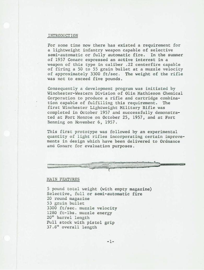
For some time now there has existed a requirement for a lightweight infantry weapon capable of selective semi-automatic or fully automatic fire. In the summer of 1957 Conarc expressed an active interest in a weapon of this type in caliber .22 centerfire capable of firing a 50 to 55 grain bullet at a muzzle velocity of approximately 3300 ft/sec . The weight of the rifle was not to exceed five pounds.
Consequently a development program was initiated by Winchester-Western Division of Olin Mathieson Chemical Corporation to produce a rifle and cartridge combination capable of fulfilling this requirement. The first Winchester Lightweight Military Rifle was completed in October 1957 and successfully demonstrated at Fort Monroe on October 25, 1957, and at Fort Benning on November 6, 1957.
This first prototype was followed by an experimental quantity of light rifles incorporating certain improvements in design which have been delivered to Ordnance and Conarc for evaluation purposes.
MAIN FEATURES
5 pound total weight (with empty magazine) Selective, full or semi-automatic fire 20 round magazine 53 grain bullet 3300 ft/sec. muzzle velocity 1280 ft-lbs. muzzle energy 20" barrel length Full stock with pistol grip 37.6" overall length
-1-
DESIGN PHILOSOPHY
From the very beginning of the development work on the Winchester Light Rifle it was considered of utmost importance that reliability must not be sacrificed to obtain low weight. As a consequence a policy decision was taken that the new Lightweight Rifle was to be designed on the basis of well proven earlier guns whose field reliability had been established in extensive tests. As a result the best elements were taken from the Winchester .30 Caliber Experimental Light Rifle, the G30R Semi-automatic Rifle, the WAR Automatic Rifle and the .50 Caliber Semi-automatic Anti Tank Rifle, to serve as a basis for development of the Winchester Lightweight Rifle.
By basing t he development of the new rifle on proven elements, the extensive testing experience gained with the earlier rifles, was utilized for the new Lightweight Rifle, yielding a weapon design of good inherent reliability and short development time to production status .
During the extensive development of the weapon a great number of significant changes were incorporated, resulting in improved function and facilitated production. A key feature of the rifle is that all sub-assemblies are functionally self-contained. Since none of the sub-assemblies rely on adjacent components for primary function, difficulties due to tolerance accumulations are eliminated.
To assure reliability under field conditions it was decided from the start that only steel was to be used for primary action parts. Consequently, barrel, receiver and all parts subject to dynamic loading are manufactured from steel to obtain high strength and wear resistance . Aluminum 7075-T6 is used only in components where no dynamic forces or
-2-
impact occur . A typical example of such a part is the trigger guard which has to withstand only static forces . The stock of the Lightweight Rifle is American walnut .
Low weight is thus achieved by sound design using conventional materials without compromise of gun life .
/
-3-
DESCRIPTION OF DESIGN FEATURES
(1) Magazine
Aluminum magazine of 20 round capacity.
(2) Ga s System I
Short stroke piston requires no cleaning or disassembly during life of gun.
(3) Barrel
Externally fluted for weight reduction and increased cooling surface without sacrifice to rigidity. Separated by an annular air space from the stock to improve cooling and avoid stock burning.
(4) Fire Control
Full automatic firing is controlled by a timing bar, which is carried forward by the slide until the bolt is l ocked, and then released by a cam lug on the barrel. Flying rearward it strikes a rocker arm which trips the hammer catch thus firing the rifle. The type of fire is controlled by a change lever on the left side front end of the receiver. When this lever is turned forward, action is full automatic; when turned to the rear for semi-automatic fire the timing bar is sprung out preventing contact with the slide.
(5) Sights
The rifle is equipped with a blade type front sight and a two-position flip over sight, mounted
-4-
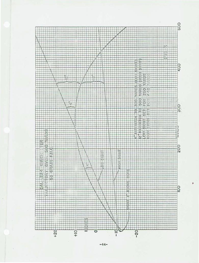
on the rear of the receiver. The low setting of the rear sight is adjusted for 250 yards and the high setting for 440 yards.
With the low sight setting a maximum mismatch 'between line of sight and point of bullet impact of 4 inches is obtained from the muzzle to 300 yards with the mismatch increasing to 1? inches at 360 yards . With the high setting a maximum mismatch of 12 inches is obtained from 360 yards to 500 yards.
This two-position flip-over rear sight is extremely simple and is capable of quick adjustment. A trajectory curve and the line of sights superimposed is shown on page 44.
(6) Safety
The safety sleeve retracts the hammer from the sear and also closes the opening in the receiver to prevent entry of sand or other foreign matter. Removal of the safety requires a combined rearward and lateral motion which prevents the safety from being easily knocked out of the safe position.
(7) Firing Pin
Retracted mechanically during the first part of the unlocking of the bolt and held in retracted position during the entire longitudinal movement of the gun mechanism. It is released only after bolt is closed and locked . This prevents the firing pin from contacting the primer during feeding or ejecting, and therefore the rifle can only be fired when the bolt is fully locked.
(8) Extractor
A mechanical feature of the extractor is that it is mechanically closed into the extractor cut in
-5-
the shell by the cam cut in the receiver when the bolt rotates and is locked in this position when the shell is fired.
(9) Bolt
The bolt incorporates the following design features: The lugs are exceptionally ~arge relative to the size of the bolt. Locking surface rotates into a helix locking cam. The cam's surface that operate on the closing and opening cams on the operating slide equal a long helix. This long sloping cam allows the operating slide to exert greater force on locking and unlocking of the bolt. The surface that the slide contacts when carrying the bolt forward also has a helix cam. It is impossible to fire the gun when the bolt is open.
(10) Stock
One-piece American Walnut with pistol grip. In assembling the action into the stock there is an interference horizontally between the takedown pin and the guard shoulders, which have a narr ow projection to prevent the stock from spreading due to climatic variations. The dimension from the upper to the lower takedown plates is greater than the spread between the bottom of the receiver and the tang on the guard. These features maintain the action under constant spring tension both horizontally and vertically, when assembled. The barrel is supported by the front band. When the gun is assembled there is a space between the barrel and the wood, the action being supported by the upper takedown plate and the front band. This
-6-
design feature prevents the stock from burning under intensive firing. The holes in the side of the hand guard are to allow the escape of trapped heat.
, (11) Bolt Hold Open Device
The principle features of the bolt hold, open device are that the bolt stop automatically locks the bolt open when the last shot is fired from the magazine. The bolt will remain open after the empty Tllagazine is removed and a loaded one inserted. Following insertion of the loaded magazine the bolt stop is released by pulling the slide handle rearward.
(12) Field Stripping
This gun can be field stripped in a few second . without tools. Details of field stripping are given on Page 18.
(13) Takedown and Assembly
The complete take down and assembly is simple and can be accomplished with a few standard tools. An armorer's kit is available to facilitate takedown. (See page 24).
(14) Uni t Design
Guard, bolt,and receiver units are self-contained and do not rely on adjacent parts for their primary operation. This permits interchangeability of units and facilitates function checks.
-7-
(15) Mate rial
The material of all primary action parts is high grade alloy steel. Functional parts have a case hardened surface to assure and maintain reliability. The guard and magazine are made of 75ST6 aluminum; hardcoated; the butt plate and front barrel support band are of 24ST aluminum.
/
-8-
TECHNICAL DATA
GENERAL
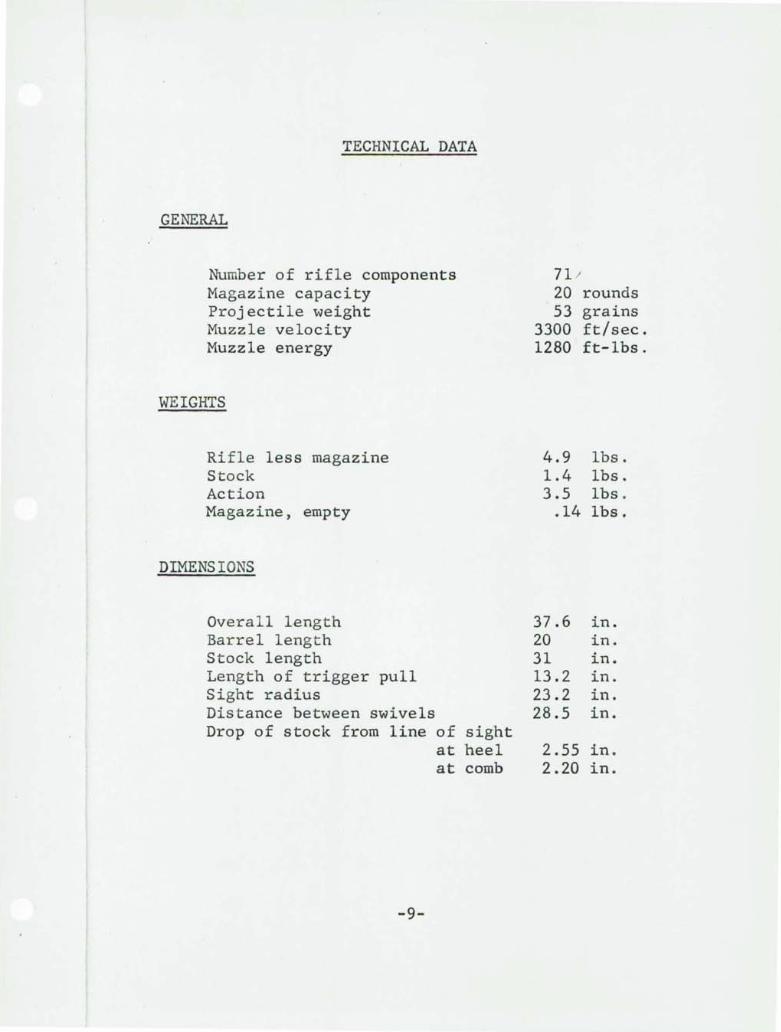
Number of rifle components Magazine capacity Projectile weight Muzzle velocity Muzzle energy
WEIGHTS
Rifle less magazine Stock Action Magazine, empty
DIMENSIONS
Overall length Barrel length Stock length Length of trigger pull Sight radius Distance between swivels Drop of stock from line of
at at
-9-
sight heel comb
71 1 20 rounds 53 grains
3300 ft/sec. 1280 ft-lbs.
4.9 1.4 3.5
.14
37.6 20 31 13.2 23.2 28.5
2.55 2.20
lbs. lbs. lbs. lbs.
in. in. in. in. in. in.
in. in.
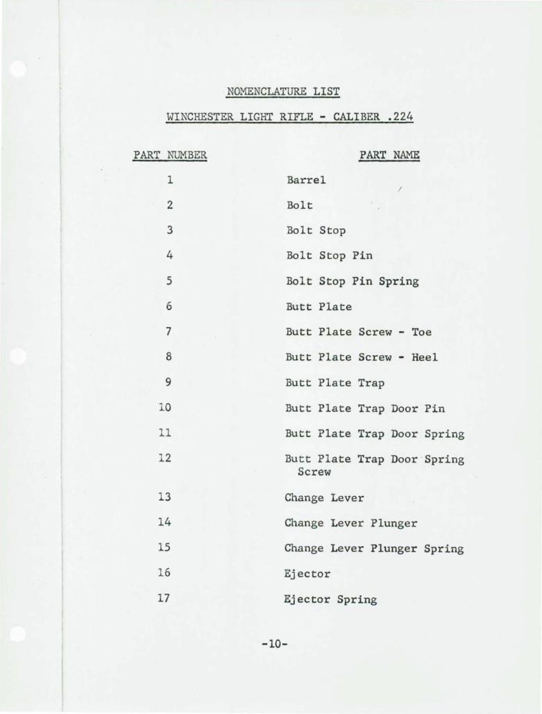
NOMENCLATURE LIST
WINCHESTER LIGHT RIFLE - CALIBER .224
PART NUMBER
1
2
3
4
5
6
7
8
9
10
11
12
13
14
15
16
17
PART NAME
Barrel I
Bolt
Bolt Stop
Bolt Stop Pin
Bolt Stop Pin Spring
Butt Plate
Butt Plate Screw - Toe
Butt Plate Screw - Heel
Butt Plate Trap
Butt Plate Trap Door Pin
Butt Plate Trap Door Spring
Butt Plate Trap Door 'Spring Screw
Change Lever
Change Lever Plunger
Change Lever Plunger Spring
Ej ector
Ejector Spring
-10-
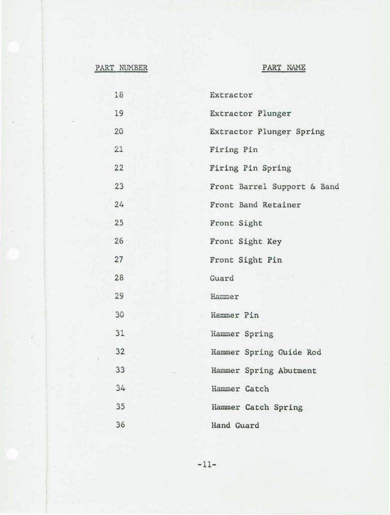
PART NUMBER PART NAME
18 Extractor
19 Extractor Plunger
20 Extractor Plunger Spring /
21 Firing Pin
22 Firing Pin Spring
23 Front Barrel Support & Band
24 Front Band Retainer
25 Front Sight
26 Front Sight Key
27 Front Sight Pin
28 Guard
29 Hammer
30 Hammer Pin
31 Hammer Spring
32 Hanuner Spring Guide Rod
33 Hammer Spring Abutment
34 Hammer Catch
35 Hammer Catch Spring
36 Hand Guard
-11-
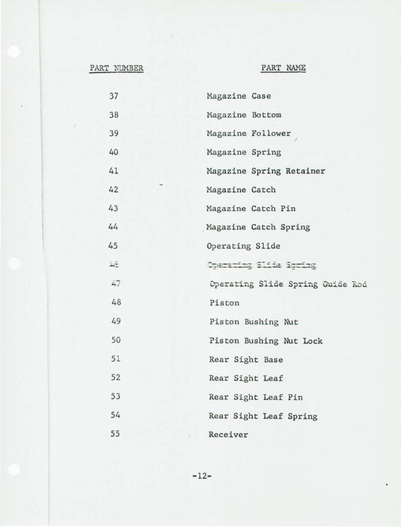
PART 1\ruMBER PART NAME
37 Magazine Case
38 Magazine Bottom
39 Magazine Follower /
40 Magazine Spring
41 Magazine Spring Retainer
42 Magazine Catch
43 Magazine Catch Pin
44 . Magazine Catch Spring
45 Operating Slide
.J... _
47 O?erating Slide Spring ~uide ~od
48 Piston
49 Piston Bushing Nut
50 Piston Bushing Nut Lock
51 Rear Sight Base
52 Rear Sight Leaf
53 Rear Sight Leaf Pin
54 Rear Sight Leaf Spring
55 Receiver
-12-
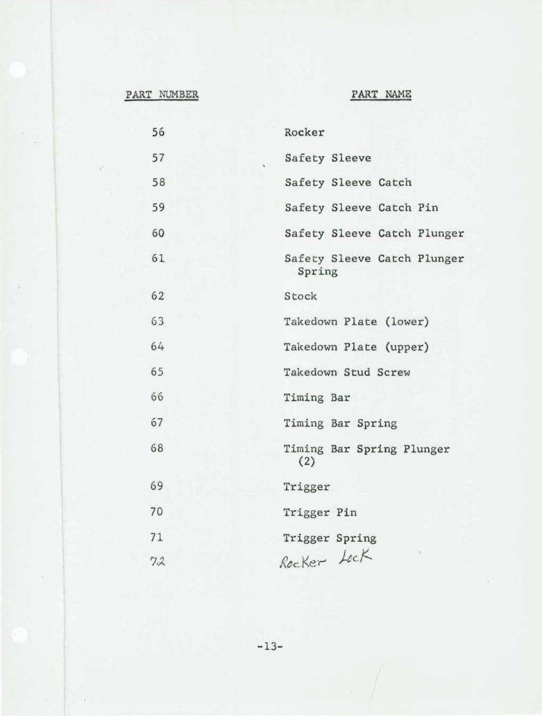
PART NUMBER
56
57
58
59
60
61
62
63
64
65
66
67
68
69
70
71
PART NAME
Rocker
Safety Sleeve
Safety Sleeve Catch
Safety Sleeve Catch Pin
Safety Sleeve Catch Plunger
Safety Sleeve Catch Plunger Spring
Stock
Takedown Plate (lower)
Takedown Plate (upper)
Takedown Stud Screw
Timing Bar
Timing Bar Spring
Timing Bar Spring Plunger (2)
Trigger
Trigger Pin
Trigger Spring
~tc."Ke·r' Her...
-13-
OPERATING INSTRUCTIONS
WINCHESTER LIGHT AUTOMATIC RIFLE CALIBER .224
Loading the Magazine
Load magazine by normal method of pressing cartridges into place under the lips of the magazine with thumb. Capacity - 20 cartridges in staggered row.
Inserting the Magazine
Insert the open end of magazine into rectangular opening in underside of stock. Force it upward in place until it is held by magazine catch. When the magazine is locked in place the magazine catch will be flush with the outside of the trigger bow. Make certain that the magazine is securely locked.
To Remove Magazine
The magazine may be released by grasping the magazine with the ~eft hand with the thumb in the trigger bow compressing the catch forward then exerting a downward pull on the magazine removing it from the guard. An alternate method is to push the magazine catch forward with the right hand thumb and pull the magazine downward with the left hand out of the trigger guard.
Feeding the Cartridge into the Chamber and Cock the Hammer
With the safety catch in the "off" position, grasp the handle of the operating slide with the right hand and pull it fully back cocking the hammer. Release the handle of the operating slide and allow the slide to go forward. This carries the cartridge into the chamber and the gun is now .ready to fire when the trigger is pulled.
-14-
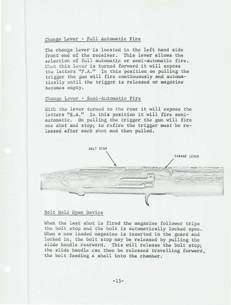
Change Lever - Full Automatic Fire
The change lever is located in the left hand side front end of the receiver. This lever allows the se lection of full automatic or semi-automatic fire. \~ Cn this l8ve~ is turned forward it will expose
. th~ le tters "F.A." In this position on pulling the trigger the gun will fire continuously and automatically until the trigger is released or magazine becomes empty.
Change Lever - Semi-Automatic Fire
With the lever turned to t he rear it will expose the letters "S.A." In this position it will fire semiautomatic. On pulling the trigger the gun will fire one shot and stop; to refire the trigger must be released after each shot and then pulled.
CHAIIGE LEVER
.4'_"==-"--"' '' r ,. ., ... .
Bolt Hold Open Device
When the l ast shot is fired the magazine follower trips the bolt stop and t he bolt is automatically locked open. When a new loaded magazine is inserted in the guard and locked in, the bolt stop may be released by pulling the slide handle rearward. This will release the bolt stop;· the slide handle can then be released travelling forward, the bolt feeding a shell into the chamber.
-15-
To Pull Operating Slide Back and Lock i t in Open Position
Pull the operating slide to the rear with the right hand. With t he left hand press the bolt stop, located on the left hand side center of the receiver, outward, letting slide forward easily until bolt contacts bolt stop. In this position the action will be locked open until released . By puliing the slide handle to the rear the bolt stop will release the bolt and allow it to return to firing position.
-16-
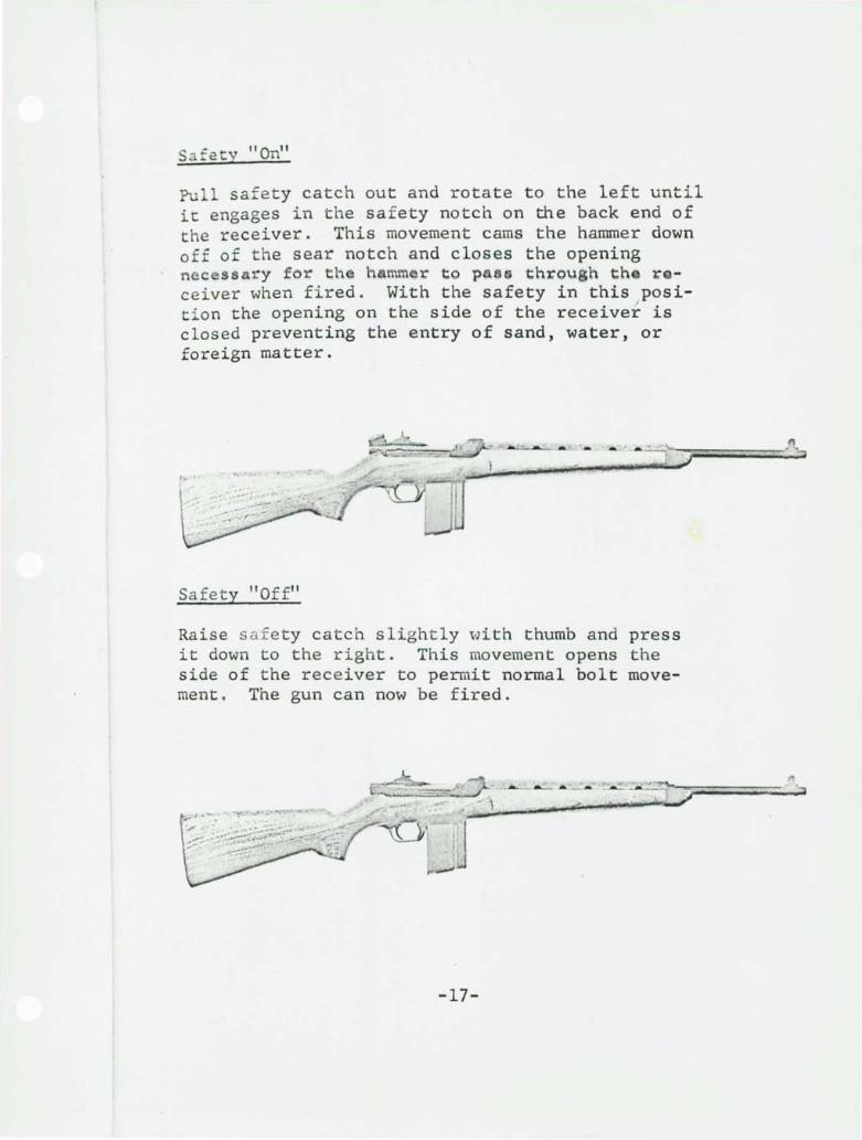
S f ety 11 On"
Pull safe ty catch out and rotate to the left until it engages in the sa f ety notch on the back end of the receiver. This movement cams the hammer down off of the sear notch and closes the opening ne e ssary for h ~ mmer to pass through th rceiver when fired. With the safety in this position the opening on the side of the receiver is closed preventing the entry of sand, water, or foreign matter.
I .
~.
Safety "Off"
Raise s a'f ety catch slightly ... ·Jith thumb and press it down to the right. This movement opens the side of the receiver to perrait normal bolt movement. The gun can now be fired.
>
-17-
FIELD STRIPPING INSTRUCTIONS
WINCHESTER LIGHT AUTOMATIC RIFLE - CAL .. 224
l. Pull the slide handle to the rear and return to its forward position. This movement will cock the hammer.
/
2. Put safety on.
3. Compress front band retainer with the thumb, at the same time pushing the front band upward with the fingers approximately 1/2" . Then remove hand guard.
4. Pu~l front band clear off stock.
To Remove Complete Action From Stock
Grasp the front end of the barrel with the left hand holding the grip of the stock firmly with the right. Li f t barrel up in an arc, it pivoting on the upper takedown plate at the rear end of the receiver until it comes clear of the stock. Then lift out and forward.
At this time the metal components are one completely assembled unit and cannot accidentally become disengaged one from the other.
To Remove Trigger Guard Assembly from Receiver
Put safety in "off" position. Pull trigger releasing hammer. Slide guard assembly to rear of receiver and lift out. Remove rocker arm by pivoting it rearward to relief cut then raising it out of the receiver.
To Remove Operating Slide Spring and Guide Rod
Grasp action in left hand by the gas port holding the slide in a forward position. With the right hand grasp
-18-
the front end o f the operating slide spring and guide rod and pull rea rward sufficient to release the plunger from the operating slide; then pull downward and out from hole.
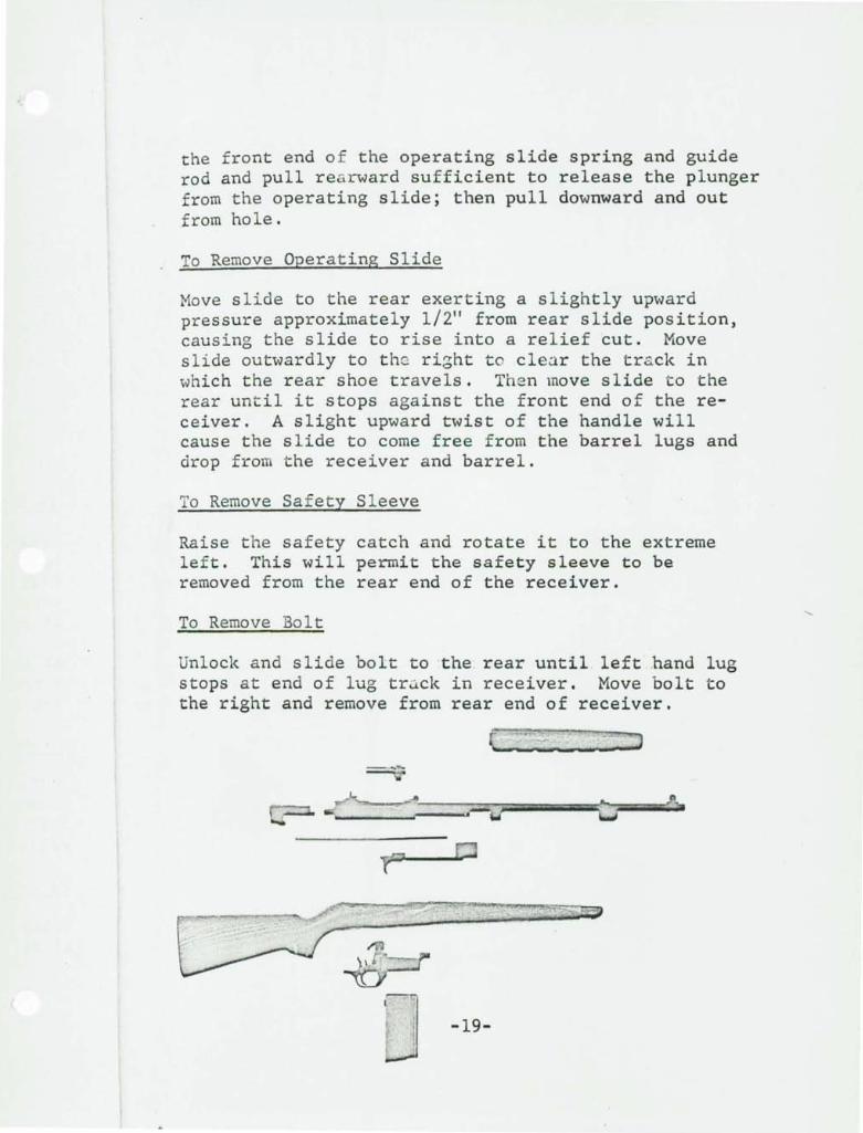
To Remove Operating Slide
Move slide to the rear exerting a slightly upward pressure approximately 1/2" from rear slide position, causing the slide to rise into a relief cut. Move slide outwardly to the right to cle~r the tr&ck in which the rear shoe travels. Then move slide to the rear until it stops against the front end of the receiver. A slight upward twist of the handle will cause the slide to come free from the barrel lugs and drop from the receiver and barrel.
To Remove Safety Sleeve
Raise the safety catch and rotate it to the extreme left. This will permit the safety sleeve to be removed from the rear end of the receiver.
To Remove Bolt
Unlock and slide bolt to the' rear until left hand lug stops at end of lug tr~ck in receiver. Move bolt to the right and remove from rear end of receiver.
It!] U -19-
TO REASSEMBLE GUN AFTER FIELD STRIPPING
To Reassemble Bolt
Check firing pi n lug to makG certain that it is in line with the bolt lug by rotating it to the right edge of the firing pin cut in the bolt. Rot~te receiver assembly to bring right side of receiver up. Place bolt in safety sleeve hole with it bearing on the up side. Push forward until bolt is stopped by the front end of the safety sleeve hole. Grasp the exposed lug and shake it slightly allowing left hand lug to drop into lug slot in receiver. Push bolt forward and into place .
Caution: If the lower lug does not readily drop into place this is due to the fact that the lug on the firing pin has moved relative to the bolt lug. To correct this, turn receiver upside down, take the guide rod and push the firing pin lug downward into its proper location. Then turn receiver to the right (right side up) and the bolt will drop into its proper location. Push bolt forward to locked position.
To Reass emble Safety Sleeve
Place safety sleeve in the rear end of the receiver with safety catch pulled out as far as possible and rotated to the extreme left on top of the receiver ledge. Push safety sleeve in until it stops against the forward shoulder of the safety sleeve hole. Pull safety catch up and rotate safety sleeve to the extreme right, release safety catch locked in the "on" position.
Place timing bar in semi-automatic position.
-20-
To Reassemble the Operating Slide
Move bolt lug to rearmost position. Engage operating slide onto exposed bolt lug and right track on barrel. Turn slide handle down until it picks up the left hand track on the barrel. Push slide forward for approximately 1/2" by exerting pressure on it. The shoe on the slide will then drop into the relief cut in the side of t he receiver and downward into the lower track. Push the slide forward.
To Reassemble Operating Slide Spring and Guide Rod
Insert operating slide guide rod into operating slide spring. Place spring and spring hole in receiver. fingers in the right hand the spring onto the guide ting slide guide rod into slide.
rod into operating slide Hold the spring with dw and feed approximately 2" of rod, then place end of operaretaining hole for same in
Caution: If, on assembly it is attempted to push the spring into the hole in the receiver, it can become bent or mutilated.
Turn receiver bottom side up and place trunnion on rocker arm in rocker arm hole in receiver with end of clearance cut on right hand side of receiver. Drop in place and rotate forward against timing bar.
To Reas s emble Trigger Guard Assembly
With receiver bottom side up, place guard assembly into bottom side of receiver with end of hammer in line with rear cut in receiver. Place guard in receiver until stop shoulders on guard contact bottom of receiver. Push guard assembly forward until it comes in contact with stop in receiver and magazine cuts in receiver and guard are in alignment. Check and make sure that rocker arm is located properly between the end of timing bar and hammer catch .
-21-
Hold action in the left hand holding the guard forward with the fingers against the thumb on the front end of the receiver. This is necessary to hold the two components together.
Place the rear end of the guard against any stationary obj ect. Place the left hand on the barrel fOrYJard of the gas piston pushing the action against t~e stationary object. With the right hand pull the slide to the extreme rear cocking the hammer. Return the operating slide with the hand to its forward position. With the hammer cocked the guard is locked into its position and the complete gun assembly will not come apart, only when the hammer is released.
T ke t he stock in right hand. Grasp the action near the piston and insert rear end of guard into stock until end of receiver contacts upper takedown plate. Using care hook hole in receiver over takedown pin, then slightly press fore-end of barrel downward in an arc into the stock, sliding the hand to the front end of the barrel. Push downward until action is straight in the stock. In performing this operation you will feel a normal spring tension between the takedown pin and the stop shoulders on the guard.
Caution: If excessive force is required for rotating the action into proper position, check to ensure that units are properly assembled and that there is not foreign matter lodged in stock or action.
Slide the front band onto the front end of stock. With the finger on the right hand compress the retainer and with the left hand push the front band to within approximately 1/4" to 1/2" of its final location. Holding the gun in the left hand and the
-22-
hand guard in the rigl t,place hand guard on top of the stock with the rear tenons locked onto the receiver. In this position push the front band into its final location.
Note: The front band retainer has locked the ............. band into place.
/
The gun is now ready to fire after inserting a magazine and feeding a shell into the chamber.
-23-
TAKEL O:';4' , " 71 ASSEMBLY INSTRUCTIONS
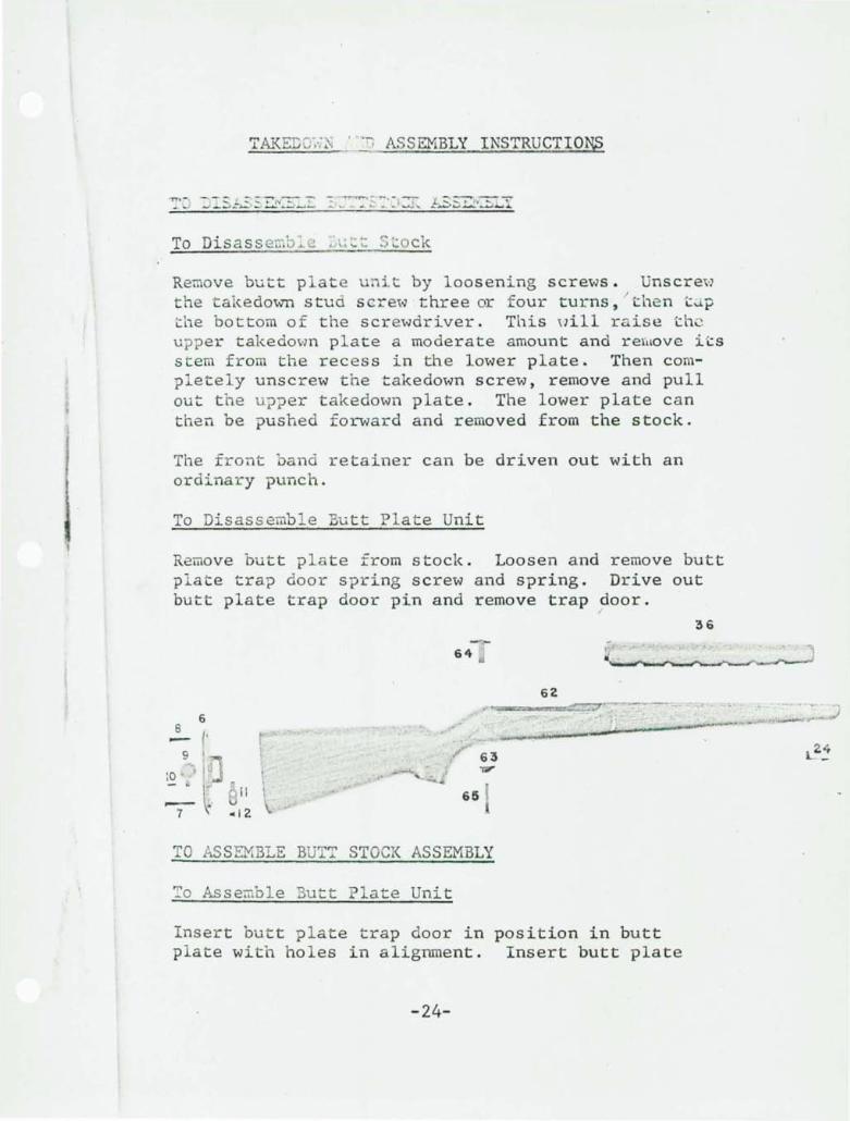
To Disass emv.. . c:k
Remove butt plate unit by loosening screws. Unscrew the takedown stud scre~,,) three or four turns, / then "j,: P the bottom of the scretoJdriver. This oill raise "the upper takedown plate a moderate amount and rerllove i "ts stem from the recess in the lower plate. Then completely unscrew the takedown screw, remove and pull out the u??er takedown plate. The lower plate can then be pushed fOl~ard and removed from the stock.
The front band retainer can be driven out with an ordinary punch.
To Disassemble Butt Plate Unit
Remove butt plate from stock. Loosen and remove butt plate trap door spring screw and spring. Drive out butt plate trap door pin and remove trap door .
. '
6
!- I'
10 ' '
- .' 7
t'
11
64
65
63 ..,.
TO AS SEMBLE BUT~ STOCK ASSEMBLY
~o Assemble But t Plate Unit
62
Insert butt plate trap door in position in butt plate with holes in alignment. Insert butt plate
-24-
36
- - . -\7::'~ E, =rev; :l~..L.:' ~ =r..:-:'~
? aLe, insert b tt plate trap door screw and tighten with a suitable screwdriver.
To Assemble Butt Sto~
Place butt plate unit onto stock and tighten butt plate screws. Drive the front band retainer into place. Insert the lower takedown plate in the stock and push to the rear. Place upper takedown plate into the hole in the stock and push it into place. This will lock the lower plate into its position. Insert takedown stud screw and tighten securely.
-25-
TO DISASSEMBLE BARREL-RECEIVER ASSEMBLY
To Di sassemble Gas Piston Bushing Lock
Place the end of the guiclc rod under the tail of the lock at the underside of the hole in the barrel and pry upw rd nd out al''l lock will spring into hole and can then readily be lifted out of the top.
/
To Disassemble Gas Piston and Bushing Lock Nut
Using the wrench furnished with the annorer's kit, loosen and remove the piston bushing lock nut. The gas piston may then be lifted out of the cylinder.
Note: Nonnally it should never be necessary to disassemble and assemble the gas piston, bushing nut, etc. during the life of the barrel.
To Disassemble Timing Bar
Tip the gun with the left side of the receiver upward. Put the change lever onto "F.A.". Hold receiver with left hand and with the right hand spring bar upward slightly and slide it ba~k until the lug on the bar comes out through the groove for it in receiver. The timing bar spring and plunger will now be free to be removed from the "T" slot in receiver.
To Disassemble Change Lever
To remove the change lever, place tapered end of guide rod under the change lever finger piece and pry upward releasing it from the plunger. Change lever can then be lifted out. With the guide rod the change lever plunger and spring can also be removed from the receiver.
-26~
- -
To Disassemble Safety Sleeve
Hold safety sleeve in ~he left hand and with the thumb remove spring tei, e; i on from safety catch pin. It can then be pushed O \.1 t with the guide rod. The safety catch can now be l iZted from the lug on the 'safety sleeve. The safety sleeve catch plunger and spring can then be removed.
I
To Disassemble Front Sigh~
Drive out the sight pin off front end of barrel. The front sight can then be readily removed. The front barrel support and band can now be slid off the front end of the barrel.
To Disassemble Rear Sight
Press it downward removing the spring tension from the sight pin and push outward. This pin is held in place by a relief cut in the assembly.
Caution: To remove rear sight base or adjust for windage - the sight cut is tapered so that with the barrel pointing forward the sight is driven from the right to left. When assembling it drives from the left to right.
To Disassemble Bolt Stop
Drive out roll pin and remove bolt stop by pulling out and working it dm'lTIward so as to relieve bolt stop spring.
Caution: When bolt stop comes loose spring is apt to fly and get lost as it is free in retaining hole.
-27-
57
58 59
601 "6(
68 67 68
r . ~. ~ ~
66
52 3
&.. 0 13
53 - 4 51 & -
54 5 I
~~ ....... , " .....
48 iii 0 49
46 c..:..u.:~I""··!!! III'I!t!'!C"'!f"!!!II!I'''W .. t!'''''!tt .. " .. """" ....... " ... """"'JNJIIU:~/N::
r-' . 50 47
45
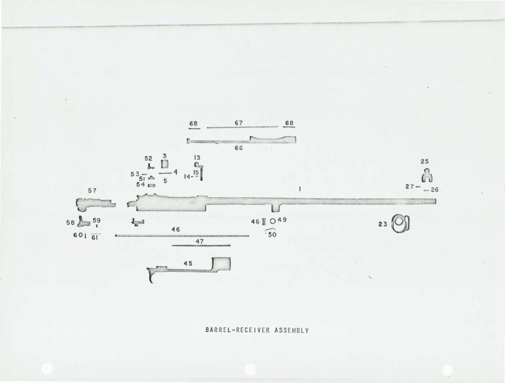
BARR EL -RECEIVER AS SEMB LY
25
~ 27- 26
23
"
TO ASS EMBLE BARREL-RECEIVER ASSEMBLY
To Assemble Gas Pi ston Bushing Lock
In sert straight end of bushing l ock, from the front, i nt o the s lot in the cylinder and t he slot in the pis ton nut. Press thumb on the end of the lock inserted, to retain it in place. Lift bushing lock up and rotate forward until it snaps into the lock hole in the cylinder. Tap spring until tail locks i t into place on the underside of hole.
To Assemble Gas Piston and Bushing Lock Nut
Insert gas piston i n t o cylinder on barrel and screw i n gas piston bushi ng lock nut until it contacts stop shoul der and one of the cuts for the wrench is in line with the notch in the gas cylinder.
To Ass emb l e Rear Sight
To assemb l e t h e base with the barrel pointing forward, drive from right to left. Lay spring on top of s i ght , press sight downward until sight pin holes line up, drive pin in place. The pin should remain locked in position due to the recess in pin.
To As semble Front Sight
First place t h e front band on the barrel. Drive sight over key until sight pin hole lines up, then drive sigh t pin into place.
To Assembl e Timing Bar
Tip the receiver with its left side up. Take the timing bar s pring assembly (spring and two plungers) and insert in t he top side of the "T" slot in receiver. Lay the timing bar lug over the relief cut in the receiver "T" slot. With the right hand press the timing bar down through the relief cut by
-29-
springing i t and with the left hand slide the timing bar ahead approximately 1/8". With it locked in th i s position take the end of the operating slide guide rod and pull the operating slide spring back i nto its position until the plunger stops against t he end of the change lever. Slide the timing bar f orward letting it nap into its operating position . During the assembly of this component the ch~nge lever should be on "F.A." position.
To Assemble Change Lever
Insert the change lever plunger and spring int o t h e change lever plunger hole. Locate in position with the end of the guide rod. Insert the change lever into the change lever hole in the receiver with the finger piece pointing to the right. Push downward until the increased diameter on the lever reaches the receiver then rotate to the front and compress into its normal postion.
To Assemble Saf ety Sl eeve
Insert the safety sleeve spring and plunger assembly into the plunger hole. Place the safety sleeve catch on top and compress until holes line up. Push in safety catch pin; the recess in center of pin wil l prevent it from falling out.
To Ass embl e Bo l t Stop
Place bo l t stop spring in hole in bolt stop. Enter bolt stop in receiver until spring contacts side of receiver. With armorer's assembly punch compress spring and push bolt stop into receiver until tool con tacts wall of receiver. Pull ass embly punch out of spring while holding the bo lt stop in place. This will leave the spring half in the receiver. The bolt stop can then be pushed fully into its location and the spring will snap into the bolt stop spring hole in the receiver.
-30-
The bolt sto ....... an be held in place w" th a 3/32" piece of rod and then a standard 3/32 x 1" ~:- 11 pin driven into the bo lt stop pin hole in the r l ceiver.
Note: Each time this component i s disassembl ed and a s sembled, a new roll pin should be used to obtain the best results in preventing it from jarring loose due to the loss of spring tension.
Alternate Method of Assembling Bolt Stop
Place act i on in a suitable vise clamped by the barrel with the left side of receiver facing upward. Insert the bolt stop spring in spring hole in the receiver. Holdi ng bolt stop in position being certain that the angular surface is towards the muzzle, take a small screwdrive r and guide the opposite end of spring into the spring hole in the bolt stop. The bolt stop is then tipped inward slightly and eased into position in the receiver so that the pin may be driven in, be certain that spring has not been kinked when the bolt stop is eased into position. Insert bolt stop pin and drive into place.
-31-
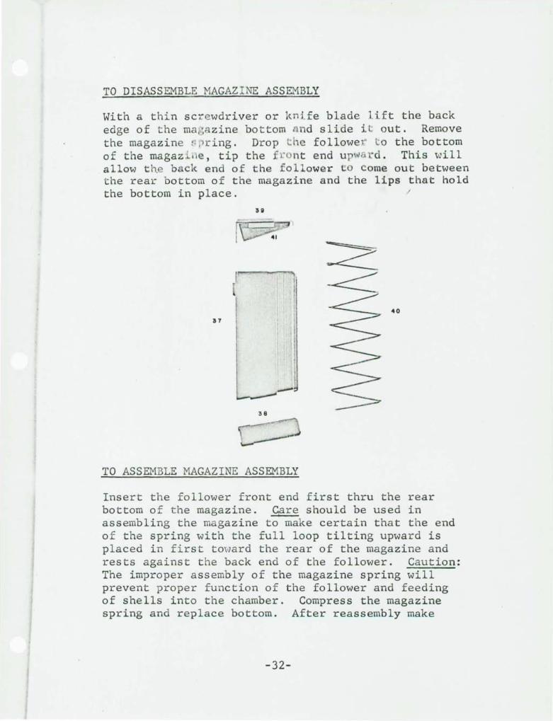
TO DISASSEMBLE MAGAZI NE ASSEMBLY
With a thin sc rewdriver or kni fe blade l ift the back edge of t he ma i-;azine bottom nnd slide i t: out. Remove the magazine " ,lr ing. Drop t he followel' t o the bottom of the magaz l .e , tip the f ~o nt end up~a ~d. This will al l ow t h~ b k end of the f ol l ower co Come out between the rear bottom of the magazine and the lips that hold the bottom in place. I
~--'-l
40
37
----38
TO ASSEMBLE MAGAZINE ASSEMBLY
Insert t h e follower front end first thru the rear bottom of t he magazine. ~ should be used in assembling the magazine to make certain that the end o f the spring with the full loop tilting upwar d is placed in first toward the rear of the magazine and rests against the back end of the follower. Caution: The improper assembly of the magazine spring will prevent proper function of the follower and feeding of shells into the chamber. Compress the magazine spring and replace bottom. After reassembly make
-32-
certain that shells lay properly between the follower and the lips on the magazine. If the shells are not resting in this position the bolt wi ll not pick them up and fe ~ d them satisfactory. This condition can be corrected by making certain that the spring has been assembled properly or by increasing the angle slightly on the first coil of the spring that rests against the follower.
-33-
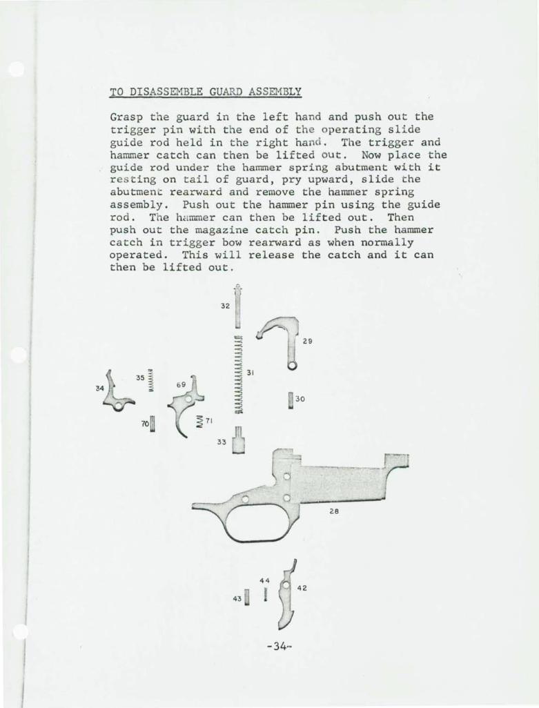
TO DISASSEMBLE GUARD ASSEMBLY
Grasp the guard in the left hand and push out the trigger pin with the end of the operating slide guide rod held in the right hand. The trigger and hammer catch can then be lifted Out . Now place the guide rod under the hammer spring abutment with it res ting on tail of guard, pry upward, slide the abutment rearward and remove the hammer spring assembly. Push out the hammer pin using the guide rod. The hammer can then be lifted out. Then push out the magazine catch pin. Push the hammer catch in trigger bow rearward as when normally operated. This will release the catch and it can then be lifted out .
32
70
33
t -< ----: -""" -. --~ 31 -. ----= -. -~ --~
43
29
30
r .----------28
44
! 42
-34-
TO ASSEMBLE GUARD ASSEMBLY
Place magazine catch spring into spring hole. Put magazine catch through top of guard, push downward and forward until it snaps into position. With the
. finger inside of the guard against the magazine catch and the thumb outside, press forward until the hole lines up with hole in guard. Insert magazine catch pin. Put hammer through top of guard lining it up with hammer pin hole .. Insert hammer pin. Grasping the guard in the left hand take hammer spring assembly and locate the hammer spring guide rod in recess on underside of hammer. Feed abutment up angle on top side of guard until it snaps into place. Function hammer up and down to make sure that abutment and guide rod are properly located.
Assemble the trigger spring to the trigger and insert the hammer catch spring into the rear hole in the trigger. Assemble the hammer catch to the trigger f irst compressing the rear spring with the end of the guide rod to allow assembly. Take this assembly and insert it into the guard as near the rear as possible to make certain that the trigger spring is properly located in the cut in the guard. Holding the guard in the left hand with the thumb against the top of the hammer catch press downward until the hammer catch and trigger hole line up with the trigger pin hole in the guard. The use of the tapered slave pin would help to facilitate the assembly of these components . Push trigger pin into trigger pin hole in guard.
Caution: Do not pull trigger and release hammer allowing it to strike guard. Prevent this from happening with thumb when checking function.
-35-
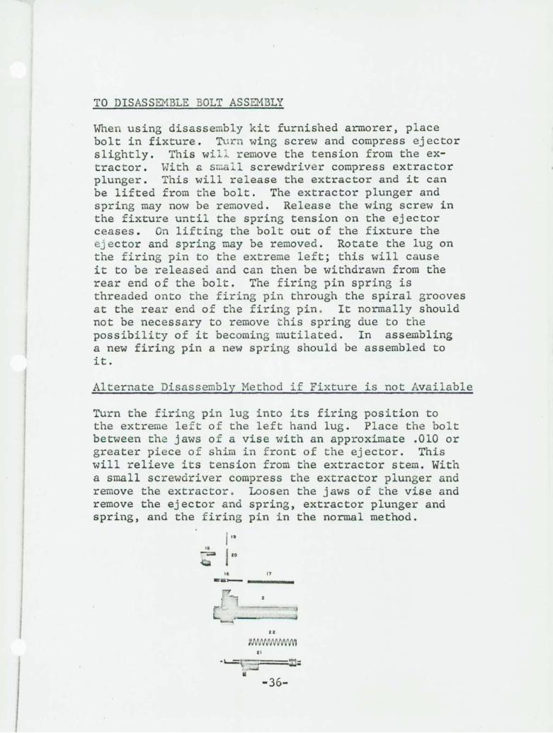
TO DISASSEMBLE BOLT ASSEMBLY
When using disassembly kit furnished armorer, place bolt in fixture. Turn wing screw and compress ejector slightly. This wi l l remove the tension from the extractor. With a sllial l screwdrive r compress extractor plunger. This will release the extractor and it can be lifted from the bolt. The extractor plunger and spring may now be removed. Release the wing screw in the fixture until the spring tension on the ejector ceases. On lifting the bolt out of the fixture the ej ector and spring may be removed. Rotate the lug on the firing pin to the extreme left; this will cause it to be released and can then be withdrawn from the rear end of the bolt. The firing pin spring is threaded onto the firing pin through the spir.al grooves at the rear end of the firing pin . It normally should not be necessary to remove this spring due to the possibility of it becoming mutilated. In assembling a new firing pin a new spring should be assembled to it.
Alternate Disassembly Method i f Fi xture is not Available
Turn the f i r i ng pin lug i nto its firing position to the extreme le f t of the left hand lug. Place the bolt between t he jaws of a vise with an approximate .010 or greater piece of shim in front of the ejector. This will relieve its tension from the extractor stem. With a small screwdriver compress the extractor plunger and remove the extractor. Loosen the jaws of the vise and remove the ejector and spring, extractor plunger and spring, and the firing pin in the normal method.
i " 18
120 -;;::a
16 n .. _---
22
21
I
-36-
TO ASSEMBLE BOLT ASSEMBLY
Insert the firing pin from the rear into the firing pin hole compressing the firing pin spring and rotate the firing pin lug to the right in line with the bolt lug. Insert the ejector and ejector spring assembly into the ejector hole with the extractor cut in a vertical position from the bolt lugs. Take the extractor spring and plunger assembly and insert in the extractor plunger hole. Place bolt with components as assembled into fixture and compress ejector by turning wing screw the amount necessary to locate the ejector below the outer rim of the bolt. Take the .160 slave pin and pass it through the extractor trunnion hole. In doing this the ejector will be rotated to proper alignment. Place extractor in bolt holding the fixture with the left hand with the thumb on top of the extractor. With a small screwdriver in the right hand, compress the extractor plunger with the thumb pressing the extractor in place.
Release the wing screw in the fixture and remove the bolt.
Alternate Assembly Method if Fixture is not Available
Assemble the firing pin, ejector and spring, and extractor plunger and spring in the normal manner. Turn the firing pin to the left of the left lug on the bolt in the approximate firing position. Place the bolt between the jaws of a vise with a piece of shim in front of the end of the ~jector, compress ejector to its location. (Note: Cut in ejector lines up with extractor hole). With the thumb on top of the extractor, with a small thin screwdriver or knife blade in the right hand, compress the extractor plunger with the thumb pressing the extractor into place.
-37-
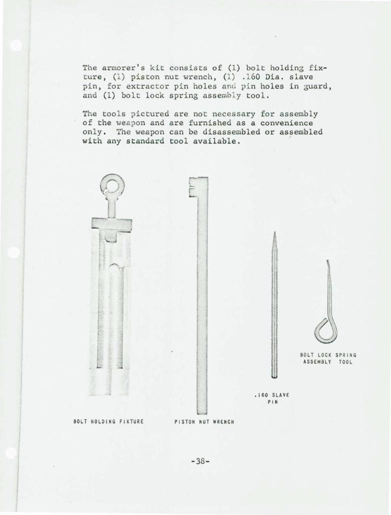
The armorer's ki t consists of (1) bolt holding fixture, (1) piston nut wrench, (1) . 160 Dia. slave pin, for extrac to r pin holes anG pin holes in guard, and (1) bolt lock spring assemb l y tool.
The tools pictured are not necessary for assembly of the weapon and are furnished as a convenience only. The weapon can be disassembled or assembled
I
with any standard tool available.
(0) ... }
i I s :
lJ
BOLT HOLDING FIXTURE
r r ~-
PISTON NUT WRENCH
-38-
.160 SLAVE PIN
BOLT LOCK SPRING ASSEMBLY TOOL
Caliber .224 Winchester E2 Ammunition
This newly developed cartridge has the following characteristics:
Bullet: 53 grain Full Metal Case I
Muzzle Velocity: 3300 ft/sec.
Max. Ave. Chamber Pressure: 52,000 psi
Barrel Length: 20"
Max. Cartridge Overall Length: 2.170"
The following figures show in detail the characteristics of this ammunition:
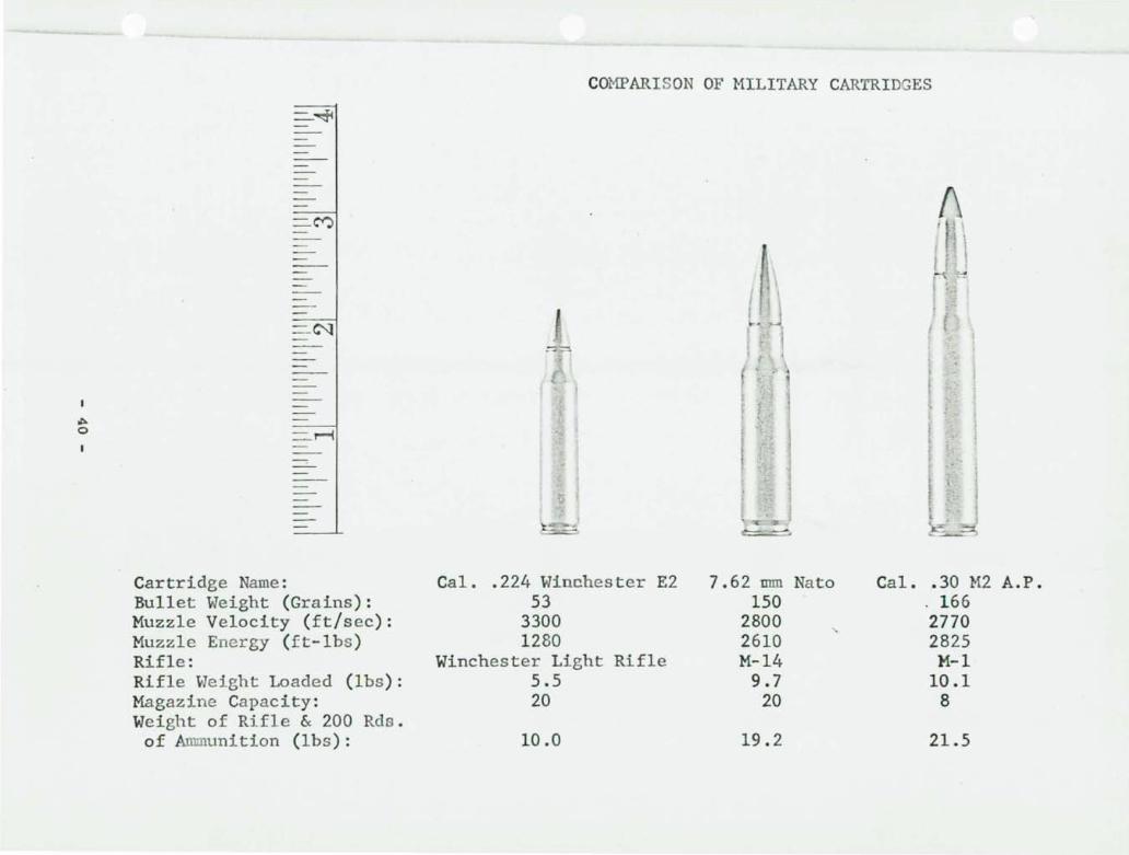
Photograph showing comparison of the Caliber .224 Winchester E2 Cartridge to other military cartridges.
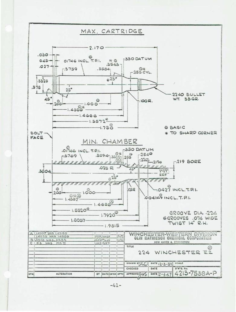
Drawing of maximum cartridge and minimum chamber dimensions.
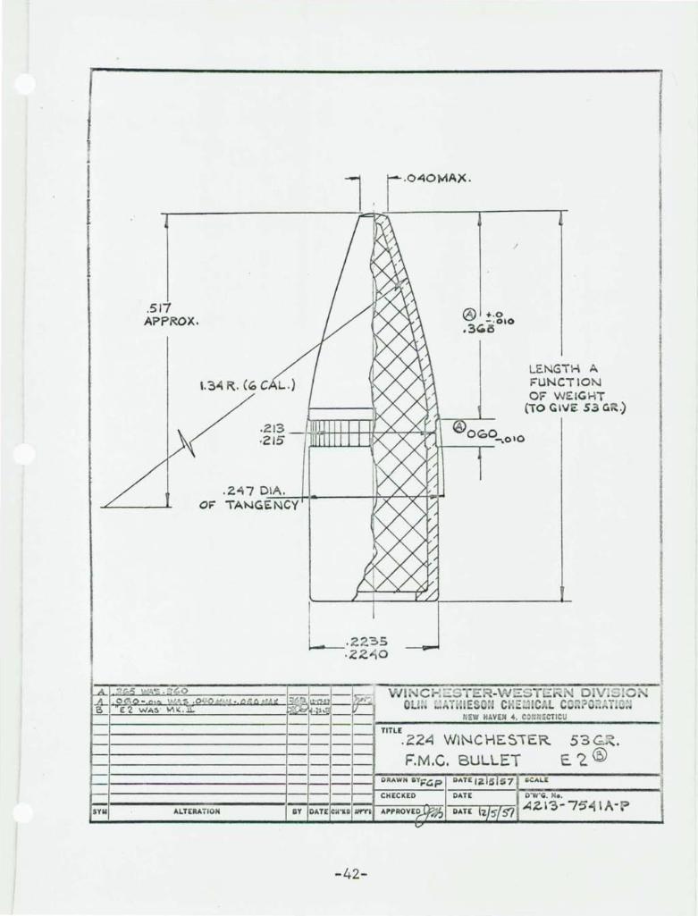
Drawing of 53 grain Full Metal Case bullet.
Tabulation of velocity, energy and mid-range trajectory at range to 500 yards.
Trajectory curve showing bullet height above or below line of sight for both low and high Light Rifle sight settings at ranges to 500 yards.
-39-
~ o
-~
=-M
=--C"l
=-~
Cartridge Name: Bullet Weight (Grains): Muzzle Velocity (ft/sec): Muzzle Energy (ft-lbs ) Rifle: Rifle Weight Loaded (lbs): Magazine Capacity: Weight of Rifle & 200 Rds. of Ammunition (lbs ):
COMPARISON OF MILITARY CARTRIDGES
A T-!'
Cal. .224 Winchester E2 7.62 mm Nato Cal • . 30 M2 A.P. 53 150 . 166
3300 2800 "-
2770 1280 2610 2825
Winchester Light Rifle M-14 M-l 5.5 9.7 10.1 20 20 8
10.0 19.2 21.5
MAX. CAI'2TRIDGE
1--------- '2,17 0 ---------~
~$ ,~S~
.35 4
.330 DATUM
$~ .'25~ CYl...
r ~O~'"i
FAC
....... ---1.000--...; 0 ...
........ --1. 4~ G ------~
1------ \. 4~<o ~ ----~
....... ------ \. &51 '20 ~---~ o
~--------1. '7 0
tv) I . CHAM BEl< .~30 DA"" UM
@ 1-------- \ . 46 ~~F_-~
~-- \, S'lO"'---------,~~
1--------- \.'7920 ----< ... 1
1---- \.
~-------- 1.9 8 15
1-----------1--- TITLE
J--·I------------I--I-- --I--·f-----------I----I--~-----------I----
:254 .1'2~
" .'2'240 U ~~ti.T Wi'. 5!1G12,
G BASIC .. TO SHARP CORt-Je.~.
o .0427 \NCL.".P.\.
GROQ'JE. DI .. '2 6G\(OO'JE.S.0 WI\)
TW\ T 14" ~.~.
W\~CH
1---1------------1---- -- ---}~~~~~~--___r~~-------1 DRAWN DAn 1'2,.3-51 CCAU:
-----------~-_I-- __ L ._ .. ---:c:-=.,....::--=-I OAT[ 0 ·CO .....
Y I ALTERATION IV OAT[ . ' ltD AlPT i DATI/2 - ~ -s 7 4 '21 ~ -75 3
-41-
I •
I I
.517 APPROX.
.2.13 ·c15
.2.4. 7 D.~IA.....:..:..".' -+~------i~~~-f9ol-I OF' TANGENCY
/
® ... . 0 - · 010
.3~l5
LENGTH A F"UNCTION OF WEIGHT
(TO GiVe: S3 Cot .)
I
t---I-----------I----~ ..... ---....;;.::.;;:..;:.;.;;.:.:;.;.;..;:.:...:;;.;;.:;;~:.-----~ TITLE
.22~ WINCHES'TER.
F.M.C. BULLET
1------------1---53~ .
E'2.@ 1--1-----------1---1--1-----------1---1--1-----------1---t---I-----------I---- -- --+~::::_:~~~~:'T:"T~r_::::~-------~
gllAWN B'I'FGP gATE IZ 5 $7 ilGALE
.--I-----------~-- - CHECKED DATE D·W·CO. No.
5'1'11 ALTERATION Y DA ni-c;c-'.-gll-IIf"(-"II. f---___ - ----.-T"-r-=-I A Z. \ '3 - 75' ~ , A· P
-42-
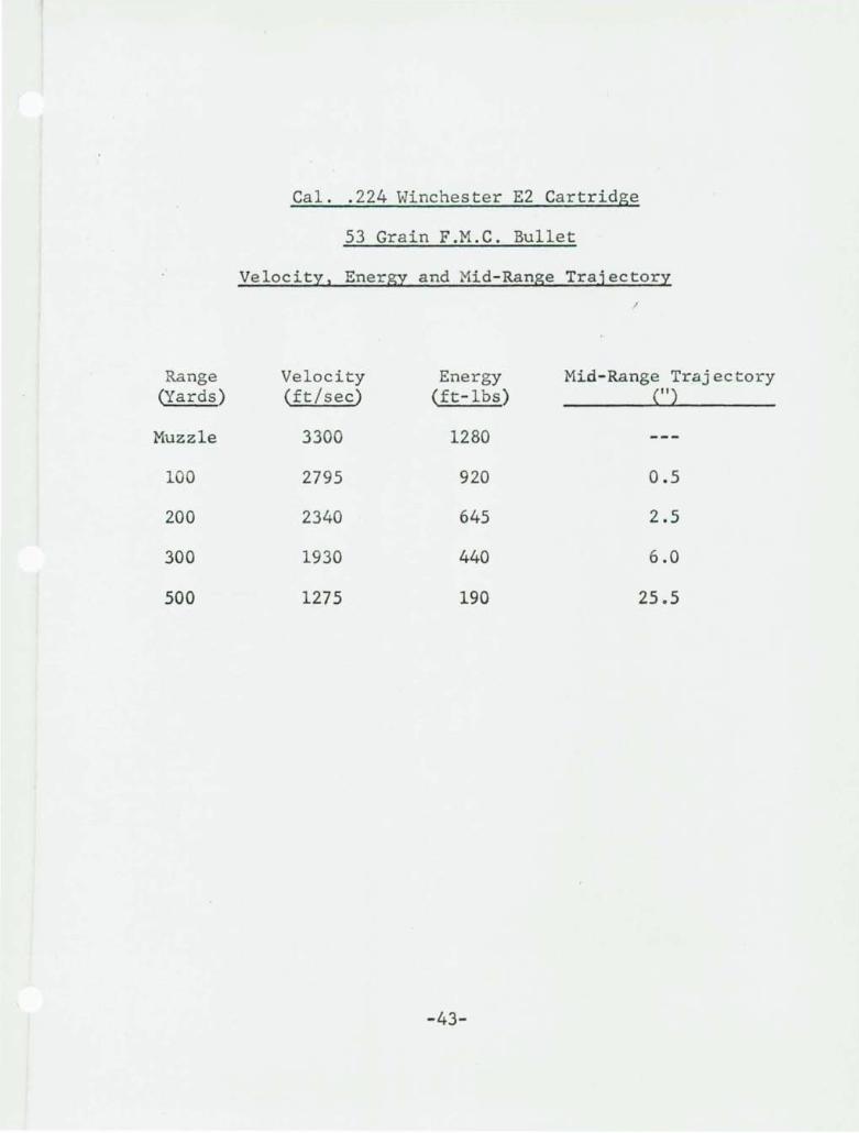
Cal .. 224 Winchester E2 Cartridge
53 Grain F.M.C. Bullet
Velocity, Energy and Mid-Range Trajectory I
Range Velocity Energy Mid-Range Trajectory (Yards) (ft/sec) (ft-lbs) (")
Muzzle 3300 1280
100 2795 920 0.5
200 2340 645 2.5
300 1930 440 6.0
500 1275 190 25.5
-43-
"i
I
. " - -
, .,.. ...
~ .
..
I
1 '-
9 N +
-
.,... '-
~ , "
~~ -I;
""
I
0 0 \,. ~
+
-44-
o N I
, ,
r ~
r:
"J . 1'0. '
::r-
f Lll
.... ~
"ii , ~
I I' ..
I
:
t .. o o .,
Is? ~
""
!A I~ ·
'~. :') .
)
r.a ;~
h
~
h ~ ~
(
. I. · 1
July 22, 1963
HISTORY OF DEVELOPMENT OF CAL. 22 CENTER FIRE MILITARY CARTRIDGE
1. Remington, under contract with Springfield Armory, during 1957, developed a new Cal. 22 Center Fire cartridge, based on the 222 Remington but with overall length increased 0.2" This ammunition was used by Springfield Armory for an "in house" Light Rifle developmene program. This cartridge waS designated by Remington as the "Cal. 22 Experimental", and is shown in the attached cartridge-chamber drawing #42l3-7534A-P.
2. Winchester-Western, also during 1957, developed the Cal. 224 Winchester E2, which is shoWn in the attached drawing, #4213-7538A-P. This cartridge, also based on a modified 222 Remington case, was developed with company funds for the Winchester Cal. 224 Light Rifle. -
3. Armalite developed the Cal. 22 AR-15 Rifle and chambered it for the Cal. 224 Winchester cartridge.
4. The Government purchased ammunition for their evaluation of the Cal. 224 AR-15 Rifle and the Cal. 224 Winchester Light Rifle from both Winchester and Remington.
a) Winchester's load was designated the Cal. 224 Winchester E2.
b) Remington's load was designated the "Cal. 222 Special".
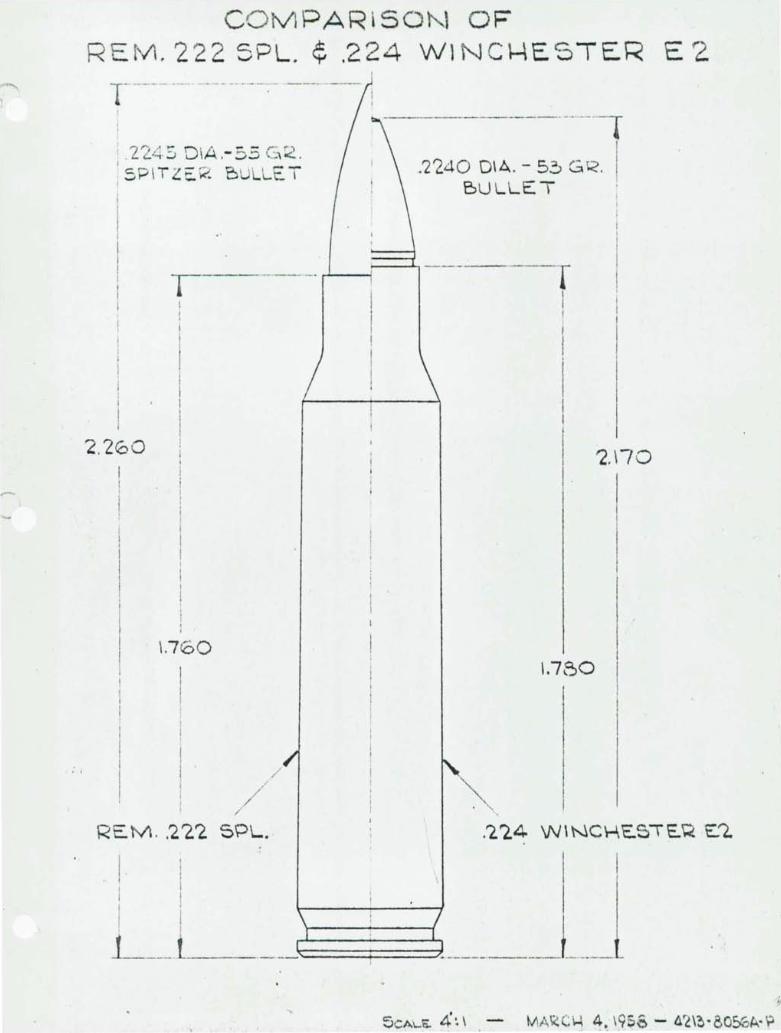
5. Remington's Cal. 222 Special was identical to the Cal. 224 Winchester except in two minor respects.
a) Case length was .020" shorter
b) A different bullet was used, resulting in an increase in overall length from 2.17~' for the Winchester cartridge to 2.26~' for the Remington cartridge.
Both of these cartridges were fired from the Cal. 224 Winchester E2 chamber. The attached sketch, dated March 4, 1958, compares the two cartridges.
CO MPAR150l'-.1 OF REtll. 222 5PL. ¢ .224 W1NCl-4E5TER E 2
1------- --- --- -- ---, ---- -- !
2"" " r- D IA - - ,.. ") " L:-t':; ,- :;):J ,_ or:::.. I
5P ITZE K B UllE. T
-r-l--- -- - -_. r-L-----l
2.200
I 1
\.760
I I
I I . /
! I
REM . . 2'2.1 SPL.
-_._---_., .'2'240 OIA. - 5~ GR. I
BULLET
T I I
1.760
I I
'2. \70
~---"-,. ______ L