manual spp bomba horizontal ingles
DESCRIPTION
PumpTRANSCRIPT
TECHNICAL INSTRUCTIONS
W12-008EISSUE 0
Our policy is one of continuous improvement and we reserve the right to alter specifications of our products at any time Page 1 of 24
THRUSTREAM RANGE
OF
SPLIT CASE PUMPS
INSTALLATION & OPERATION FOR FM / UL FIRE PUMPS
TB08D (FM/UL) TB10D (FM/UL) TF20E (FM/UL)
TB08E (FM/UL) TB10E (FM/UL) TF20F (FM/UL)
TC12F (FM/UL) TB12E (FM/UL) TE10A (FM)
TC12G (FM/UL) TB12F (FM/UL) TE10D (FM/UL)
TD10E (FM/UL) TB12D (FM/UL) TE12E (FM/UL)
TD12F (FM/UL) TB15E (FM/UL) TF15E (FM/UL)
TD15F (FM/UL) TE15D (FM/UL) TY12D (FM/UL)
TD20D (FM/UL) TE15E (FM/UL) TY15E (FM/UL)
TD20E (FM/UL) TF20D (FM/UL)
SPP Pumps Inc.,6710 Best Friends Road,
Norcross, GA, 30071, USA. Telephone: (770) 447-4443. Fax (770) 447-4443.
TECHNICAL INSTRUCTIONS
W12-008EISSUE 0
Page 2 of 23
Our policy is one of continuous improvement and we reserve the right to alter specifications of our products at any time Page 2 of 24
CONTENTS1 INTRODUCTION .................................................................................................................................................... 3
1.1 GENERAL ...................................................................................................................................................... 3
1.2 WARRANTY .................................................................................................................................................. 3
1.3 PUMP IDENTIFICATION ............................................................................................................................. 3
1.4 HEALTH & SAFETY ..................................................................................................................................... 3
1.4.1 GENERAL............................................................................................................................................. 3
1.4.2 SPECIFIC RECOMMENDATIONS ................................................................................................... 4
1.5 AFTER SALES SERVICE............................................................................................................................ 6
2 INSTALLATION ....................................................................................................................................................... 7
2.1 RECEIVING PUMP....................................................................................................................................... 7
2.2 TEMPORARY STORAGE ........................................................................................................................... 7
2.3 PREPARATION............................................................................................................................................. 7
2.4 LOCATION..................................................................................................................................................... 8
2.5 FOUNDATION ............................................................................................................................................... 8
2.6 INSTALLATION OF BASEFRAMES .......................................................................................................... 8
2.7 ALIGNMENT PROCEDURE...................................................................................................................... 12
2.7.1 ANGULAR .......................................................................................................................................... 13
2.7.2 PARALLEL ......................................................................................................................................... 13
2.7.3 AXIAL .................................................................................................................................................. 13
2.8 SUCTION & DISCHARGE PIPING .......................................................................................................... 13
3 OPERATION........................................................................................................................................................... 14
3.1 BEFORE STARTING (After Installation or Maintenance) ..................................................................... 14
3.2 STARTING ................................................................................................................................................... 15
3.3 RUNNING..................................................................................................................................................... 15
3.4 STOPPING................................................................................................................................................... 15
TABLE 1 FAULT FINDING CHART ........................................................................................................... 16
TABLE 2 FAULT RECTIFICATION CHART ............................................................................................. 17
4 MAINTENANCE ..................................................................................................................................................... 18
4.1 ROUTINE MAINTENANCE ....................................................................................................................... 18
4.2 LUBRICATION ............................................................................................................................................ 18
TABLE 3 BEARING RE-GREASING INTERVALS ................................................................................... 18
4.3 BEARINGS - GENERAL ............................................................................................................................ 19
4.4 SOFT PACKED SEALING......................................................................................................................... 20
4.5 MECHANICAL SEALS ............................................................................................................................... 21
TABLE 4 ROUTINE MAINTENANCE CHART ............................................................................................... 21
TABLE 5 FIRE PUMP SOFT PACKED SEALING DETAILS ....................................................................... 22
TABLE 6 MAINTENANCE RECORD .............................................................................................................. 23
TECHNICAL INSTRUCTIONS
W12-008EISSUE 0
Page 3 of 23
Our policy is one of continuous improvement and we reserve the right to alter specifications of our products at any time Page 3 of 24
1. INTRODUCTION
1.1 GENERAL The pumps covered by this manual, when correctly installed and maintained, will give long and reliable service. It is essential that the instructions given here are followed at all times.
1.2 WARRANTY Refer to your Sales Contract for coverage.
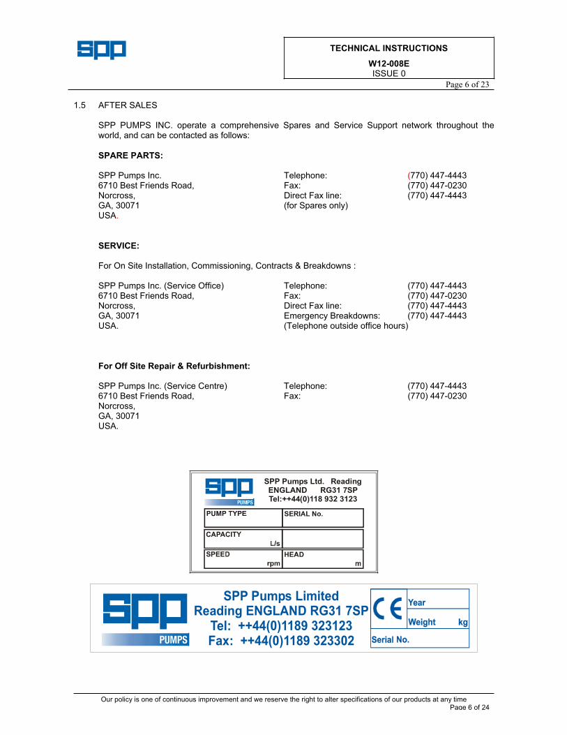
1.3 PUMP IDENTIFICATION An identification plate is attached to the body of all pumps and contains the following minimum information: PUMP TYPE, SERIAL No., CAPACITY, SPEED, HEAD.
Additional information may also be given covering impeller details, materials used, sales order line number etc. Reference should be made to this data when reading the manual.
1.4 HEALTH & SAFETY
1.4.1 GENERAL
I. QUALIFICATION AND TRAINING OF PERSONNEL Personnel responsible for the installation, commissioning, operation and maintenance of this pumpset must be adequately qualified for their respective tasks. Scope of responsibility must be defined by the operator and appropriate supervision provided. The operator should also ensure that the contents of this manual are fully understood by the personnel.
Il NON-COMPLIANCE WITH SAFETY INSTRUCTIONS Non-compliance with safety instructions may produce a risk to personnel as well as to the environment and the pumpset, and result in loss of any right to claim damages.
Risks may include: Failure of the pumpset. Exposure of people to electrical, mechanical and chemical hazards. Endangering the environment by releasing hazardous substances.
Ill COMPLIANCE WITH SAFETY AT WORK REGULATIONS When operating the pumpset, the instructions contained in this manual, the relevant national accident prevention regulations and any other service and safety instructions issued by the operator are to be observed.
IV UNAUTHORIZED ALTERATIONS AND FITTING OF SPARE PARTS Modifications should not be carried out without consultation and approval of SPP PUMPS INC. In the interests of safety and reliability only OEM spare parts supplied by SPP PUMPS INC. shall be used. Failure to comply in these respects could affect warranty.
V. UNAUTHORISED USE Pumpset performance and reliability can only be guaranteed providing if the system is used in the manner and for the purpose for which it was intended.

TECHNICAL INSTRUCTIONS
W12-008EISSUE 0
Page 4 of 23
Our policy is one of continuous improvement and we reserve the right to alter specifications of our products at any time Page 4 of 24
1.4.2 SPECIFIC RECOMMENDATIONS 1.4.2.1 Your safety and that of others must always be the first consideration when working on
machines. Safety is a matter of understanding the operations being undertaken and the potential dangers. Be on your guard at all times.
WARNING! The following health and safety recommendations must be strictly observed.
(1) While this pump set has been designed to be safe under normal operating conditions, there are potential hazards that the operator should be aware of. These can include: rotating components; electrical potentials; high temperature exhaust surfaces and gases (where diesel driven); and hazardous fluids.
(2) When lifting the unit ensure that all lifting equipment has a safe working load rating, suitable for the operation. Only perform lifting operations using suitably trained personnel, and in line with instructions contained in this manual.
(3) Persons working on the unit should always wear suitable protective clothing and footwear. Loose, frayed or baggy clothing and light footwear can be extremely dangerous. Clothing impregnated with oil or similar can constitute a health hazard through prolonged contact with the skin and may also create a fire risk. Wear protective goggles and gloves when handling battery acid.
(4) Liquids used with some pumpsets are harmful if taken internally or come into contact with unprotected skin or eyes. In the event of an accident, obtain qualified medical assistance immediately.
(5) Always use suitable masks or respirators during maintenance or other operations where there is a risk of inhalation of fibrous dust or harmful fumes.
(6) Always ensure that all safety guards supplied are correctly installed following any maintenance operation.
(7) Ensure that the pumpset is not run outside its operational limits. This can put the unit under excessive loads and cause breakdown.
(8) When working on electric motor driven pump sets, take care to see that the controller is in the "OFF" position, and a conspicuous notice is displayed warning that the unit is under repair. If a major overhaul is being carried out it is advisable to have a qualified electrician temporarily disconnect the unit.
1.4.2.2 PUMP HAZARDS
(1) Ensure that the pump has no air in the suction line or casing. The pump rotating components rely on the liquid being pumped for cooling and lubrication. A failure to prime the unit could result in pump failure.
(2) Pump operation with insufficient lubrication to the bearings could result in overheating and seizure, with potentially catastrophic results.
(3) Where soft packed sealing is used it is essential that a small leakage is present. Over tightening of the gland will result in damage to the packing, scoring of the shaft or sleeves and bearing seizure.
(4) Ensure that all pressure has been released before working on the unit.
(5) Always check that the drive shafts and couplings are correctly aligned following installation. Failure to do so could result in reduced life or a possible failure of the coupling, or bearings. (see Section 2.7).
TECHNICAL INSTRUCTIONS
W12-008EISSUE 0
Page 5 of 23
Our policy is one of continuous improvement and we reserve the right to alter specifications of our products at any time Page 5 of 24
1.4.2.3 HAZARDS RELATED TO ENGINE DRIVEN PUMPSETS
(1) When working with gaseous fuels, ensure that the area is well ventilated and avoid naked flames, smoking, sparks etc. A Carbon Dioxide fire extinguisher should be kept close at hand.
(2) Parts of the package, in particular, the exhaust system and engine surfaces can become very hot during and after operation and can cause severe burns.
(3) Beware of the danger of scalding when removing cooling system pressure caps and hoses, or draining engine oil. Allow the system to cool first, then remove caps slowly.
(4) Rectify all water, oil or fuel leaks immediately and clean up any spillage.
(5) Before carrying out any work on the pumpset confirm that the fuel and electrical supplies to the engine are isolated correctly, and that there is no danger that it can be started. A conspicuous notice should be placed on the unit warning others that the unit is under repair.
1.4.2.4 PUMPSETS FITTED WITH ELECTRONIC COMPONENTS
CAUTION Damage can occur to the internal components when electric welding or high voltage "Megger" tests are carried out. Electronic components should always be disconnected before carrying out any work of this kind.
TECHNICAL INSTRUCTIONS
W12-008EISSUE 0
Page 6 of 23
Our policy is one of continuous improvement and we reserve the right to alter specifications of our products at any time Page 6 of 24
1.5 AFTER SALES
SPP PUMPS INC. operate a comprehensive Spares and Service Support network throughout the world, and can be contacted as follows:
SPARE PARTS:
SPP Pumps Inc. Telephone: (770) 447-4443 6710 Best Friends Road, Fax: (770) 447-0230 Norcross, Direct Fax line: (770) 447-4443 GA, 30071 (for Spares only) USA.
SERVICE:
For On Site Installation, Commissioning, Contracts & Breakdowns :
SPP Pumps Inc. (Service Office) Telephone: (770) 447-4443 6710 Best Friends Road, Fax: (770) 447-0230 Norcross, Direct Fax line: (770) 447-4443 GA, 30071 Emergency Breakdowns: (770) 447-4443 USA. (Telephone outside office hours)
For Off Site Repair & Refurbishment:
SPP Pumps Inc. (Service Centre) Telephone: (770) 447-4443 6710 Best Friends Road, Fax: (770) 447-0230Norcross, GA, 30071 USA.
SPP Pumps Ltd. Reading ENGLAND RG31 7SPTel:++44(0)118 932 3123
SPP Pumps Limited Reading ENGLAND RG31 7SP
Tel: ++44(0)1189 323123Fax: ++44(0)1189 323302
TECHNICAL INSTRUCTIONS
W12-008EISSUE 0
Page 7 of 23
Our policy is one of continuous improvement and we reserve the right to alter specifications of our products at any time Page 7 of 24
INSTALLATION
2.1 RECEIVING PUMP
On receipt of pump, a visual check should be made to determine if any damage has occurred in transit. Typical points to look for are:
a Broken or cracked equipment e.g. baseframe, motor, pump feet and flanges.
b Bent shafts.
c Damaged motor end bells, bent eyebolts or damaged boxes.
d Missing items.
Loose parts are often wrapped individually and/or fastened to the equipment. If any damage or losses have occurred notify SPP PUMPS INC and the transit company immediately.
When unloading pump units, only lift the unit using the lifting eyes on the baseframe or support frame. DO NOT USE THE LIFTING POINTS ON THE PUMP OR MOTOR
Pump and motor shafts are in alignment when shipped, however the alignment must be re-checked before use.
2.2 TEMPORARY STORAGE
If the pump is not to be installed immediately it should be stored in a clean, dry area, with protection from moisture, dust, dirt and foreign bodies. In particular, the following action should be taken:
a Ensure the bearings are packed with the recommended grease, to prevent moisture from entering around the shaft.
b Remove the glands, packing and lantern rings from the stuffing box, where soft packed sealing is used.
c Check that the pump suction and discharge ports are covered to prevent foreign objects entering.
d If, for a short period only, the pump has to be stored outside it should be covered to protect it from the effects of the weather.
e Every 6 weeks, rotate the pump shaft to prevent bearing pitting.
2.3 PREPARATION
Before installing the pump, clean the suction and discharge flanges thoroughly and remove the protective coating from pump shafts, where applicable.
If the pump has been in storage and prepared in the manner as above, the bearing grease should be removed, the bearings cleaned (using an approved cleaning fluid) and then re-lubricated following the procedure detailed in Section 4. It is strongly recommended that this work is carried out by SPP PUMPS INC (see Section 1.5). This is a chargeable service; however pump warranty will be protected.
TECHNICAL INSTRUCTIONS
W12-008EISSUE 0
Page 8 of 23
Our policy is one of continuous improvement and we reserve the right to alter specifications of our products at any time Page 8 of 24
2.4 LOCATION
The pump should be installed as near to the liquid source as possible, with the shortest and most direct suction pipe practical.
Allow sufficient accessibility for inspection and maintenance, and ample headroom should be allowed for the use of an overhead crane or hoist sufficiently strong to lift the unit.
Where pumps are electric motor driven, power source electrical characteristics should be appropriate for those shown on motor data plate.
2.5 FOUNDATION
The foundation should be sufficiently substantial to absorb vibrations and rigid enough to avoid any twisting or misalignment. As a rough guide it should be 12.00 inches wider on all sides with the weight at least 1-1.5 times as heavy as the pumpset. Depth should be sufficient to achieve the necessary weight and deep enough to accommodate drilling pockets for fixing bolts.
Min. Foundation depth (feet) = W 150 x B x L
W (pounds) = total weight of pumpset; 150 (pounds/foot3)= concrete density; B (feet) = foundation width; L (feet) = foundation length
A suitable concrete mixture by volume is 1:2:3 (Cement : Sand : Aggregate) with a maximum 4.00 inches slump, and a 28 day compressive strength of 1,750 tonf/in2. The foundation should be reinforced with layers of 6.00 inches square No.8 gauge steel wire fabric, or equivalent, horizontally placed 6.00 inches apart.
Loose bolt type anchors should be checked for tightness periodically, as there is a tendency to loosen off with vibration. Chemical type anchors are a suitable alternative.
2.6 INSTALLATION OF BASEFRAMES Foundation concrete should be poured without interruption to within 0.50 inches to 1.50 inches of the finished height. The top surface should be well scored and grooved, before the concrete sets, to provide a bonding surface for the grout. The foundation should be allowed to cure for several days before the baseframe is shimmed and grouted.
Chemical Anchor type foundation bolts are recommended as these are less inclined to loosen off in service, and generally simplify installation. Manufacturer's instructions for installation and final torque figures should be rigorously followed. Allow enough bolt length for grout, shims, lower baseframe flange, nuts and washers. Fixing bolt diameter should be the largest capable of being inserted through the baseframe fixing holes.
For installation purposes, baseframes can generally be divided into 4 different categories:
Channel Section Folded Sheet Metal with side flange Folded Sheet-metal without side flange Box Section, and Cast Iron baseframes. Follow the appropriate installation procedure.
TECHNICAL INSTRUCTIONS
W12-008EISSUE 0
Page 9 of 23
Our policy is one of continuous improvement and we reserve the right to alter specifications of our products at any time Page 9 of 24
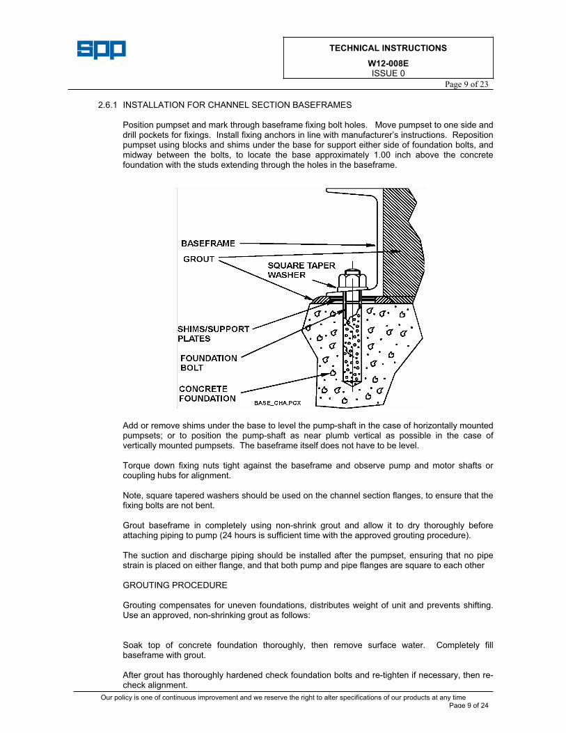
2.6.1 INSTALLATION FOR CHANNEL SECTION BASEFRAMES
Position pumpset and mark through baseframe fixing bolt holes. Move pumpset to one side and drill pockets for fixings. Install fixing anchors in line with manufacturer’s instructions. Reposition pumpset using blocks and shims under the base for support either side of foundation bolts, and midway between the bolts, to locate the base approximately 1.00 inch above the concrete foundation with the studs extending through the holes in the baseframe.
Add or remove shims under the base to level the pump-shaft in the case of horizontally mounted pumpsets; or to position the pump-shaft as near plumb vertical as possible in the case of vertically mounted pumpsets. The baseframe itself does not have to be level.
Torque down fixing nuts tight against the baseframe and observe pump and motor shafts or coupling hubs for alignment.
Note, square tapered washers should be used on the channel section flanges, to ensure that the fixing bolts are not bent.
Grout baseframe in completely using non-shrink grout and allow it to dry thoroughly before attaching piping to pump (24 hours is sufficient time with the approved grouting procedure).
The suction and discharge piping should be installed after the pumpset, ensuring that no pipe strain is placed on either flange, and that both pump and pipe flanges are square to each other
GROUTING PROCEDURE
Grouting compensates for uneven foundations, distributes weight of unit and prevents shifting. Use an approved, non-shrinking grout as follows:
Soak top of concrete foundation thoroughly, then remove surface water. Completely fill baseframe with grout.
After grout has thoroughly hardened check foundation bolts and re-tighten if necessary, then re-check alignment.
TECHNICAL INSTRUCTIONS
W12-008EISSUE 0
Page 10 of 23
Our policy is one of continuous improvement and we reserve the right to alter specifications of our products at any time Page 10 of 24
Approximately 14 days after the grout has been poured or when the grout has thoroughly dried, apply an oil based paint to the exposed faces of the grout to prevent air and moisture from coming into contact.
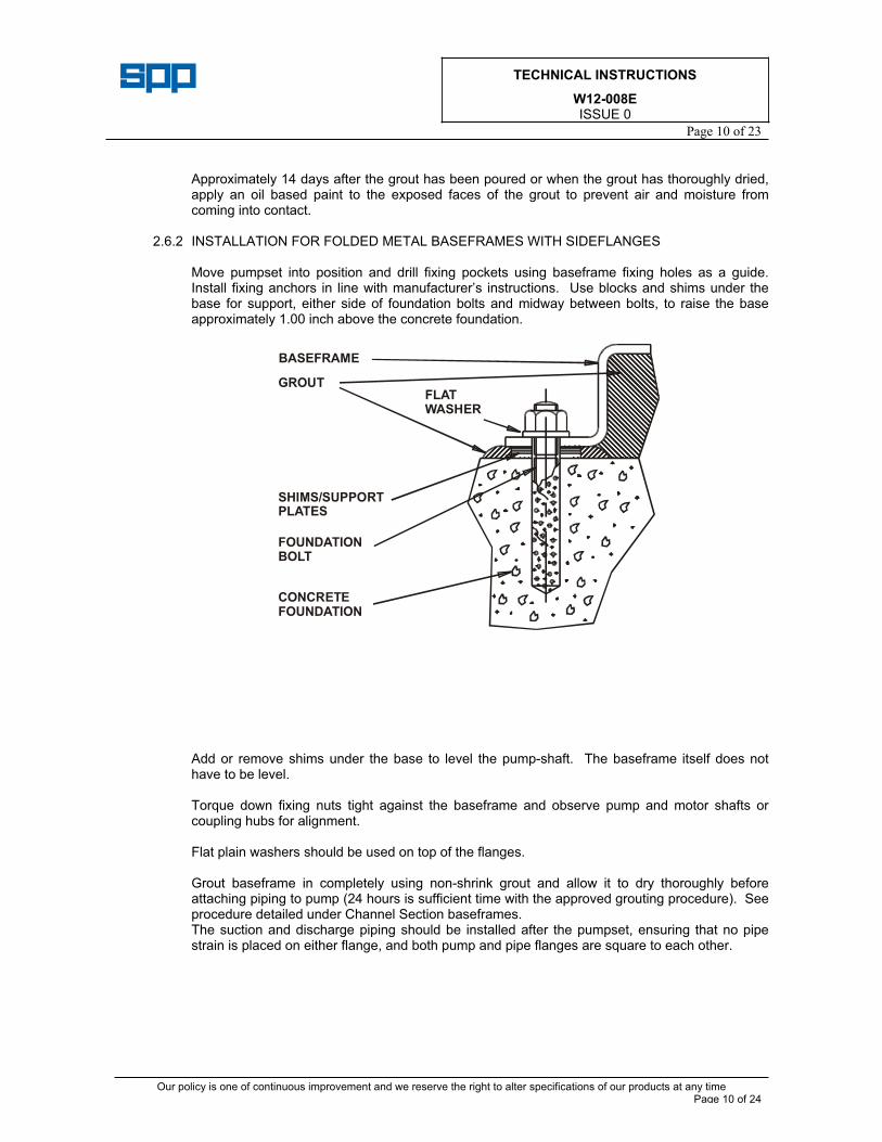
2.6.2 INSTALLATION FOR FOLDED METAL BASEFRAMES WITH SIDEFLANGES
Move pumpset into position and drill fixing pockets using baseframe fixing holes as a guide. Install fixing anchors in line with manufacturer’s instructions. Use blocks and shims under the base for support, either side of foundation bolts and midway between bolts, to raise the base approximately 1.00 inch above the concrete foundation.
Add or remove shims under the base to level the pump-shaft. The baseframe itself does not have to be level.
Torque down fixing nuts tight against the baseframe and observe pump and motor shafts or coupling hubs for alignment.
Flat plain washers should be used on top of the flanges.
Grout baseframe in completely using non-shrink grout and allow it to dry thoroughly before attaching piping to pump (24 hours is sufficient time with the approved grouting procedure). See procedure detailed under Channel Section baseframes. The suction and discharge piping should be installed after the pumpset, ensuring that no pipe strain is placed on either flange, and both pump and pipe flanges are square to each other.
BASEFRAME
GROUTFLATWASHER
SHIMS/SUPPORTPLATES
FOUNDATIONBOLT
CONCRETEFOUNDATION
TECHNICAL INSTRUCTIONS
W12-008EISSUE 0
Page 11 of 23
Our policy is one of continuous improvement and we reserve the right to alter specifications of our products at any time Page 11 of 24
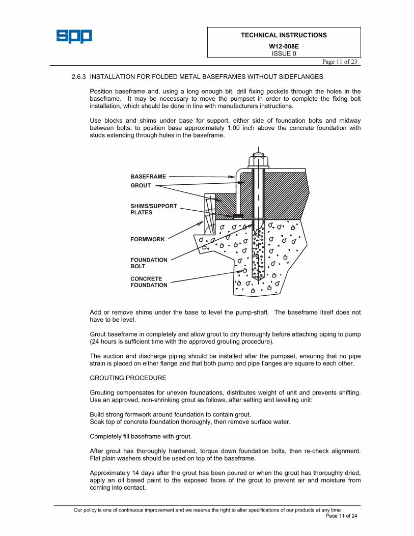
2.6.3 INSTALLATION FOR FOLDED METAL BASEFRAMES WITHOUT SIDEFLANGES
Position baseframe and, using a long enough bit, drill fixing pockets through the holes in the baseframe. It may be necessary to move the pumpset in order to complete the fixing bolt installation, which should be done in line with manufacturers instructions.
Use blocks and shims under base for support, either side of foundation bolts and midway between bolts, to position base approximately 1.00 inch above the concrete foundation with studs extending through holes in the baseframe.
Add or remove shims under the base to level the pump-shaft. The baseframe itself does not have to be level.
Grout baseframe in completely and allow grout to dry thoroughly before attaching piping to pump (24 hours is sufficient time with the approved grouting procedure).
The suction and discharge piping should be installed after the pumpset, ensuring that no pipe strain is placed on either flange and that both pump and pipe flanges are square to each other.
GROUTING PROCEDURE
Grouting compensates for uneven foundations, distributes weight of unit and prevents shifting. Use an approved, non-shrinking grout as follows, after setting and levelling unit:
Build strong formwork around foundation to contain grout. Soak top of concrete foundation thoroughly, then remove surface water.
Completely fill baseframe with grout.
After grout has thoroughly hardened, torque down foundation bolts, then re-check alignment. Flat plain washers should be used on top of the baseframe.
Approximately 14 days after the grout has been poured or when the grout has thoroughly dried, apply an oil based paint to the exposed faces of the grout to prevent air and moisture from coming into contact.
BASEFRAME
GROUT
SHIMS/SUPPORTPLATES
FORMWORK
FOUNDATIONBOLT
CONCRETEFOUNDATION
TECHNICAL INSTRUCTIONS
W12-008EISSUE 0
Page 12 of 23
Our policy is one of continuous improvement and we reserve the right to alter specifications of our products at any time Page 12 of 24
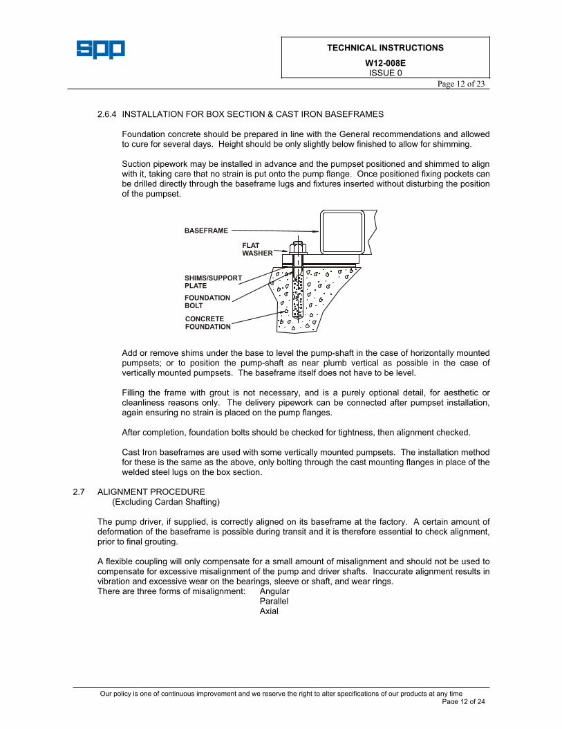
2.6.4 INSTALLATION FOR BOX SECTION & CAST IRON BASEFRAMES
Foundation concrete should be prepared in line with the General recommendations and allowed to cure for several days. Height should be only slightly below finished to allow for shimming.
Suction pipework may be installed in advance and the pumpset positioned and shimmed to align with it, taking care that no strain is put onto the pump flange. Once positioned fixing pockets can be drilled directly through the baseframe lugs and fixtures inserted without disturbing the position of the pumpset.
Add or remove shims under the base to level the pump-shaft in the case of horizontally mounted pumpsets; or to position the pump-shaft as near plumb vertical as possible in the case of vertically mounted pumpsets. The baseframe itself does not have to be level.
Filling the frame with grout is not necessary, and is a purely optional detail, for aesthetic or cleanliness reasons only. The delivery pipework can be connected after pumpset installation, again ensuring no strain is placed on the pump flanges.
After completion, foundation bolts should be checked for tightness, then alignment checked.
Cast Iron baseframes are used with some vertically mounted pumpsets. The installation method for these is the same as the above, only bolting through the cast mounting flanges in place of the welded steel lugs on the box section.
2.7 ALIGNMENT PROCEDURE (Excluding Cardan Shafting)
The pump driver, if supplied, is correctly aligned on its baseframe at the factory. A certain amount of deformation of the baseframe is possible during transit and it is therefore essential to check alignment, prior to final grouting.
A flexible coupling will only compensate for a small amount of misalignment and should not be used to compensate for excessive misalignment of the pump and driver shafts. Inaccurate alignment results in vibration and excessive wear on the bearings, sleeve or shaft, and wear rings. There are three forms of misalignment: Angular
Parallel Axial
BASEFRAME
FLATWASHER
SHIMS/SUPPORTPLATE
FOUNDATIONBOLT
CONCRETEFOUNDATION
TECHNICAL INSTRUCTIONS
W12-008EISSUE 0
Page 13 of 23
Our policy is one of continuous improvement and we reserve the right to alter specifications of our products at any time Page 13 of 24
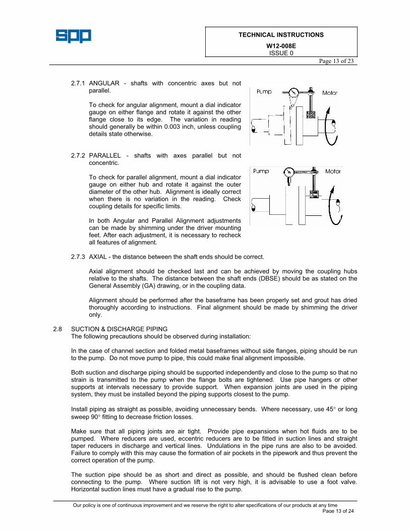
2.7.1 ANGULAR - shafts with concentric axes but not parallel.
To check for angular alignment, mount a dial indicator gauge on either flange and rotate it against the other flange close to its edge. The variation in reading should generally be within 0.003 inch, unless coupling details state otherwise.
2.7.2 PARALLEL - shafts with axes parallel but not concentric.
To check for parallel alignment, mount a dial indicator gauge on either hub and rotate it against the outer diameter of the other hub. Alignment is ideally correct when there is no variation in the reading. Check coupling details for specific limits.
In both Angular and Parallel Alignment adjustments can be made by shimming under the driver mounting feet. After each adjustment, it is necessary to recheck all features of alignment.
2.7.3 AXIAL - the distance between the shaft ends should be correct.
Axial alignment should be checked last and can be achieved by moving the coupling hubs relative to the shafts. The distance between the shaft ends (DBSE) should be as stated on the General Assembly (GA) drawing, or in the coupling data.
Alignment should be performed after the baseframe has been properly set and grout has dried thoroughly according to instructions. Final alignment should be made by shimming the driver only.
2.8 SUCTION & DISCHARGE PIPING The following precautions should be observed during installation:
In the case of channel section and folded metal baseframes without side flanges, piping should be run to the pump. Do not move pump to pipe, this could make final alignment impossible.
Both suction and discharge piping should be supported independently and close to the pump so that no strain is transmitted to the pump when the flange bolts are tightened. Use pipe hangers or other supports at intervals necessary to provide support. When expansion joints are used in the piping system, they must be installed beyond the piping supports closest to the pump.
Install piping as straight as possible, avoiding unnecessary bends. Where necessary, use 45 or long
sweep 90 fitting to decrease friction losses.
Make sure that all piping joints are air tight. Provide pipe expansions when hot fluids are to be pumped. Where reducers are used, eccentric reducers are to be fitted in suction lines and straight taper reducers in discharge and vertical lines. Undulations in the pipe runs are also to be avoided. Failure to comply with this may cause the formation of air pockets in the pipework and thus prevent the correct operation of the pump.
The suction pipe should be as short and direct as possible, and should be flushed clean before connecting to the pump. Where suction lift is not very high, it is advisable to use a foot valve. Horizontal suction lines must have a gradual rise to the pump.
TECHNICAL INSTRUCTIONS
W12-008EISSUE 0
Page 14 of 23
Our policy is one of continuous improvement and we reserve the right to alter specifications of our products at any time Page 14 of 24
The discharge pipe is usually preceded by a non-return valve or check valve and a discharge gate valve. The check valve is to protect the pump from excessive back pressure and reverse rotation of the unit and to prevent back flow into the pump in case of stoppage or failure of the driver. The discharge valve is used in priming, starting and when shutting down the pump.
The use of butterfly valves in suction lines is not recommended, however if unavoidable there should be a distance of at least 5 pipe diameters between the valve and the pump inlet flange.
FM FIREPUMP INSTALLATIONS (Loss Prevention Data 3-7N/13-4N)
Table 2-20 The diameter of the suction pipe, discharge pipe and gate valve should not be less than that shown in the Table.
Para.3-1.2 The horizontal centrifugal fire pump in horizontal or vertical position should not be used where a static suction lift is involved.
3. OPERATION
3.1 BEFORE STARTING (After Installation or Maintenance) Before initially starting the pump, make the following inspection:
The unit baseframe must be grouted (where applicable), and bolted to the foundation.
Make sure all rotating parts are found to be free when turned by hand.
Ensure motor is correctly wired to its starting device. Check that the voltage, phase and frequency on the motor nameplate are correct for the line circuit.
Confirm correct direction of motor rotation prior to coupling to pump. Check by starting motor and switching off immediately, observing rotation is the same as the arrow direction on the pump casing.
Check the alignment between pump and motor.
Check bearing lubrication is provided (see lubrication section). Also check driver lubrication.
If the pump has soft packed sealing, check that the stuffing box has been packed.
Close drain valves. Ensure that the pump is primed. Never run the unit dry. The liquid in the pump serves as a lubricant for close running fits within the pump and the pump may be damaged if operated dry. Pumps may be primed by using an ejector, exhauster or vacuum pump. If a foot valve is used in the suction line, the pump may be primed by venting and filling the casing with liquid. Vent and drain plugs are provided either in the casing, or in external pipework.
Suction pipework should have been flushed clean during installation. Failure to do this is a common reason for commissioning failures.
TECHNICAL INSTRUCTIONS
W12-008EISSUE 0
Page 15 of 23
Our policy is one of continuous improvement and we reserve the right to alter specifications of our products at any time Page 15 of 24
3.2 STARTING Close valve in discharge line. Open fully all valves in the suction line.
Turn on seal water to the stuffing box where external pipe supplied.
Prime the pump and start the pump driver. When the pump is operating at full speed, open the discharge valve slowly.
Do not operate the pump for prolonged periods with a closed discharge valve, so as to avoid overheating.
The pump should be shut down at once and the trouble corrected if the pump is running at its rated speed and found to have any of the following defects:
a No liquid delivered. b Not enough liquid delivered. c Not enough pressure. d Loss of liquid after starting. e Excess vibration. f Motor runs hot. g Pump bearing overheating.
3.3 RUNNING
While the pump is running, a periodic inspection should be made of:
Bearings Check the bearings for temperature, which should not normally exceed 158 F, after running in period.
a Stuffing Box (if Soft Packed)- Ensure there is sufficient leakage to lubricate the packing.
b Suction and discharge gauge readings (if fitted).
3.4 STOPPING
a Slowly close delivery valve then shut down driving unit in accordance with manufacturer's instructions.
b Shut off external sealing liquid supply to relieve stuffing box pressure, where fitted
c Successful operation of the pump depends on accurate coupling alignment. It is recommended that the alignment is re-checked after the preliminary run.
TECHNICAL INSTRUCTIONS
W12-008EISSUE 0
Page 16 of 23
Our policy is one of continuous improvement and we reserve the right to alter specifications of our products at any time Page 16 of 24
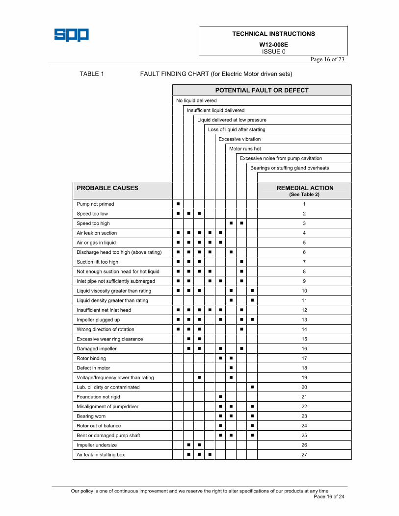
TABLE 1 FAULT FINDING CHART (for Electric Motor driven sets)
POTENTIAL FAULT OR DEFECT
No liquid delivered
Insufficient liquid delivered
Liquid delivered at low pressure
Loss of liquid after starting
Excessive vibration
Motor runs hot
Excessive noise from pump cavitation
Bearings or stuffing gland overheats
PROBABLE CAUSES REMEDIAL ACTION(See Table 2)
Pump not primed 1
Speed too low 2
Speed too high 3
Air leak on suction 4
Air or gas in liquid 5
Discharge head too high (above rating) 6
Suction lift too high 7
Not enough suction head for hot liquid 8
Inlet pipe not sufficiently submerged 9
Liquid viscosity greater than rating 10
Liquid density greater than rating 11
Insufficient net inlet head 12
Impeller plugged up 13
Wrong direction of rotation 14
Excessive wear ring clearance 15
Damaged impeller 16
Rotor binding 17
Defect in motor 18
Voltage/frequency lower than rating 19
Lub. oil dirty or contaminated 20
Foundation not rigid 21
Misalignment of pump/driver 22
Bearing worn 23
Rotor out of balance 24
Bent or damaged pump shaft 25
Impeller undersize 26
Air leak in stuffing box 27
TECHNICAL INSTRUCTIONS
W12-008EISSUE 0
Page 17 of 23
Our policy is one of continuous improvement and we reserve the right to alter specifications of our products at any time Page 17 of 24
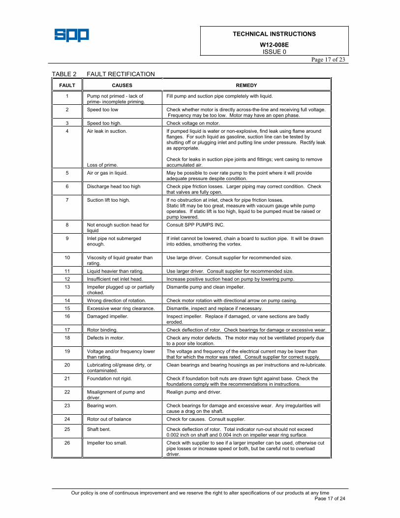
TABLE 2 FAULT RECTIFICATION
FAULT CAUSES REMEDY
1 Pump not primed - lack of prime- incomplete priming.
Fill pump and suction pipe completely with liquid.
2 Speed too low Check whether motor is directly across-the-line and receiving full voltage. Frequency may be too low. Motor may have an open phase.
3 Speed too high. Check voltage on motor.
4 Air leak in suction.
Loss of prime.
If pumped liquid is water or non-explosive, find leak using flame around flanges. For such liquid as gasoline, suction line can be tested by shutting off or plugging inlet and putting line under pressure. Rectify leak as appropriate.
Check for leaks in suction pipe joints and fittings; vent casing to remove accumulated air.
5 Air or gas in liquid. May be possible to over rate pump to the point where it will provide adequate pressure despite condition.
6 Discharge head too high Check pipe friction losses. Larger piping may correct condition. Check that valves are fully open.
7 Suction lift too high. If no obstruction at inlet, check for pipe friction losses. Static lift may be too great, measure with vacuum gauge while pump operates. If static lift is too high, liquid to be pumped must be raised or pump lowered.
8 Not enough suction head for liquid
Consult SPP PUMPS INC.
9 Inlet pipe not submerged enough.
If inlet cannot be lowered, chain a board to suction pipe. It will be drawn into eddies, smothering the vortex.
10 Viscosity of liquid greater than rating.
Use large driver. Consult supplier for recommended size.
11 Liquid heavier than rating. Use larger driver. Consult supplier for recommended size.
12 Insufficient net inlet head. Increase positive suction head on pump by lowering pump.
13 Impeller plugged up or partially choked.
Dismantle pump and clean impeller.
14 Wrong direction of rotation. Check motor rotation with directional arrow on pump casing.
15 Excessive wear ring clearance. Dismantle, inspect and replace if necessary.
16 Damaged impeller. Inspect impeller. Replace if damaged, or vane sections are badly eroded.
17 Rotor binding. Check deflection of rotor. Check bearings for damage or excessive wear.
18 Defects in motor. Check any motor defects. The motor may not be ventilated properly due to a poor site location.
19 Voltage and/or frequency lower than rating.
The voltage and frequency of the electrical current may be lower than that for which the motor was rated. Consult supplier for correct supply.
20 Lubricating oil/grease dirty, or contaminated.
Clean bearings and bearing housings as per instructions and re-lubricate.
21 Foundation not rigid. Check if foundation bolt nuts are drawn tight against base. Check the foundations comply with the recommendations in instructions.
22 Misalignment of pump and driver.
Realign pump and driver.
23 Bearing worn. Check bearings for damage and excessive wear. Any irregularities will cause a drag on the shaft.
24 Rotor out of balance Check for causes. Consult supplier.
25 Shaft bent. Check deflection of rotor. Total indicator run-out should not exceed 0.002 inch on shaft and 0.004 inch on impeller wear ring surface.
26 Impeller too small. Check with supplier to see if a larger impeller can be used, otherwise cut pipe losses or increase speed or both, but be careful not to overload driver.
TECHNICAL INSTRUCTIONS
W12-008EISSUE 0
Page 18 of 23
Our policy is one of continuous improvement and we reserve the right to alter specifications of our products at any time Page 18 of 24
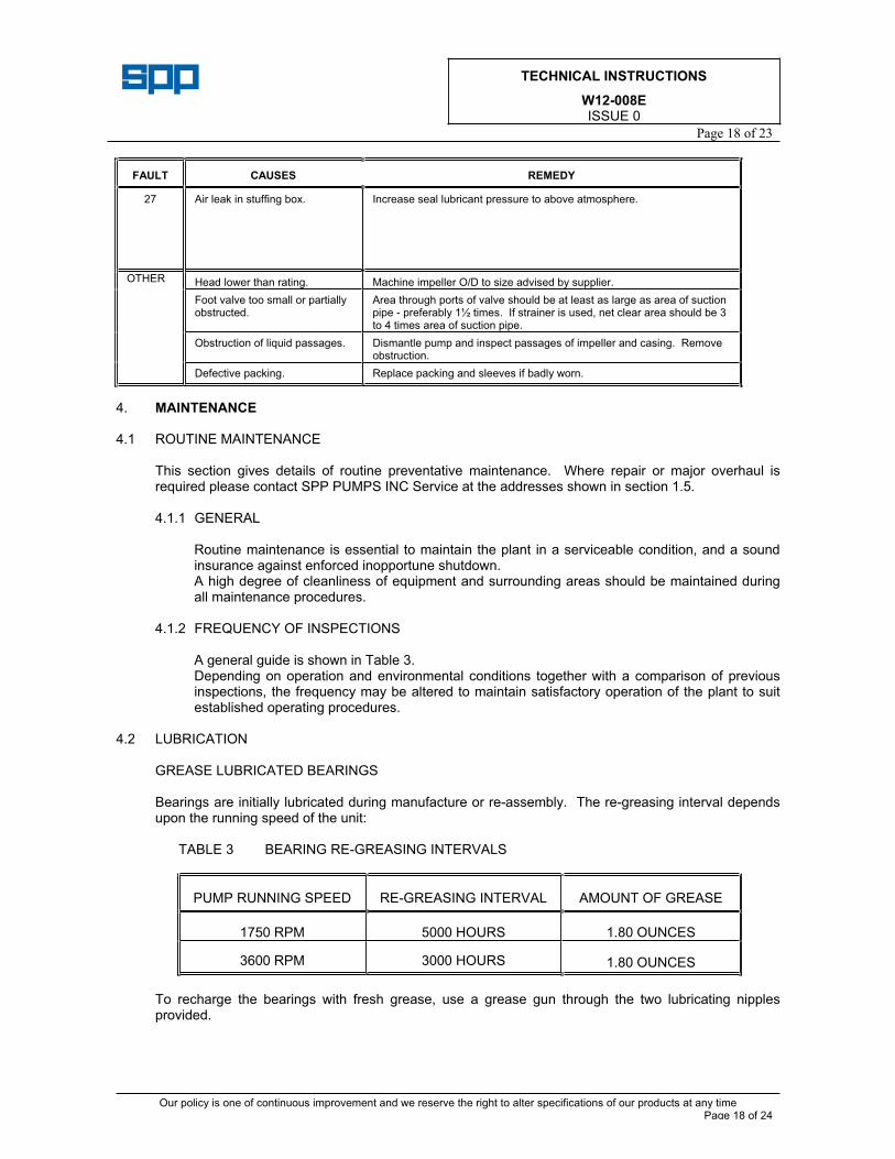
FAULT CAUSES REMEDY
27 Air leak in stuffing box. Increase seal lubricant pressure to above atmosphere.
OTHER Head lower than rating. Machine impeller O/D to size advised by supplier.
Foot valve too small or partially obstructed.
Area through ports of valve should be at least as large as area of suction pipe - preferably 1½ times. If strainer is used, net clear area should be 3 to 4 times area of suction pipe.
Obstruction of liquid passages. Dismantle pump and inspect passages of impeller and casing. Remove obstruction.
Defective packing. Replace packing and sleeves if badly worn.
4. MAINTENANCE
4.1 ROUTINE MAINTENANCE
This section gives details of routine preventative maintenance. Where repair or major overhaul is required please contact SPP PUMPS INC Service at the addresses shown in section 1.5.
4.1.1 GENERAL
Routine maintenance is essential to maintain the plant in a serviceable condition, and a sound insurance against enforced inopportune shutdown. A high degree of cleanliness of equipment and surrounding areas should be maintained during all maintenance procedures.
4.1.2 FREQUENCY OF INSPECTIONS
A general guide is shown in Table 3. Depending on operation and environmental conditions together with a comparison of previous inspections, the frequency may be altered to maintain satisfactory operation of the plant to suit established operating procedures.
4.2 LUBRICATION
GREASE LUBRICATED BEARINGS
Bearings are initially lubricated during manufacture or re-assembly. The re-greasing interval depends upon the running speed of the unit:
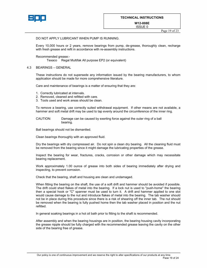
TABLE 3 BEARING RE-GREASING INTERVALS
PUMP RUNNING SPEED RE-GREASING INTERVAL AMOUNT OF GREASE
1750 RPM 5000 HOURS 1.80 OUNCES
3600 RPM 3000 HOURS 1.80 OUNCES
To recharge the bearings with fresh grease, use a grease gun through the two lubricating nipples provided.
TECHNICAL INSTRUCTIONS
W12-008EISSUE 0
Page 19 of 23
Our policy is one of continuous improvement and we reserve the right to alter specifications of our products at any time Page 19 of 24
DO NOT APPLY LUBRICANT WHEN PUMP IS RUNNING.
Every 10,000 hours or 2 years, remove bearings from pump, de-grease, thoroughly clean, recharge with fresh grease and refit in accordance with re-assembly instructions.
Recommended grease:- Texaco Regal Multifak All purpose EP2 (or equivalent)
4.3 BEARINGS – GENERAL
These instructions do not supersede any information issued by the bearing manufacturers, to whom application should be made for more comprehensive literature.
Care and maintenance of bearings is a matter of ensuring that they are:
1. Correctly lubricated at intervals. 2. Removed, cleaned and refitted with care. 3. Tools used and work areas should be clean.
To remove a bearing, use correctly suited withdrawal equipment. If other means are not available, a hammer and soft metal drift may be used to tap evenly around the circumference of the inner ring.
CAUTION: Damage can be caused by exerting force against the outer ring of a ball bearing.
Ball bearings should not be dismantled.
Clean bearings thoroughly with an approved fluid.
Dry the bearings with dry compressed air. Do not spin a clean dry bearing. All the cleaning fluid must be removed from the bearing since it might damage the lubricating properties of the grease.
Inspect the bearing for wear, fractures, cracks, corrosion or other damage which may necessitate bearing replacement.
Work approximately 1.00 ounce of grease into both sides of bearing immediately after drying and inspecting, to prevent corrosion.
Check that the bearing, shaft and housing are clean and undamaged.
When fitting the bearing on the shaft, the use of a soft drift and hammer should be avoided if possible. The drift could shed flakes of metal into the bearing. If a lock nut is used to "push-home" the bearing then a special hook or "C" spanner must be used to turn it. A drift and hammer applied to one slot would cause damage to the nut and introduce flakes of metal into the bearing. The tab washer should not be in place during this procedure since there is a risk of shearing off the inner tab. The nut should be removed when the bearing is fully pushed home then the tab washer placed in position and the nut refitted.
In general soaking bearings in a hot oil bath prior to fitting to the shaft is recommended.
After assembly and when the bearing housings are in position, the bearing housing cavity incorporating the grease nipple should be fully charged with the recommended grease leaving the cavity on the other side of the bearing free of grease.
TECHNICAL INSTRUCTIONS
W12-008EISSUE 0
Page 20 of 23
Our policy is one of continuous improvement and we reserve the right to alter specifications of our products at any time Page 20 of 24
4.4 SOFT PACKED SEALING
Fire pumps are supplied with soft packed stuffing boxes with seal lubrication via external nylon or copper pipework. Refer to Table 5 and the following when carrying out maintenance:
GLAND PACKING REPLACEMENT
Isolate pump driver, close all valves and relieve any liquid pressure. Remove gland follower, gland packing, lantern ring and split bush or neck ring (where fitted). A screw type packing ring extractor will aid removal but take care not to damage the stuffing box. During removal take careful note of the order and position of the parts so that the reverse procedure can be carried out for re assembly. Various different arrangements of sealing are employed on the Thrustream range of pumps with the following combinations of parts being three variations (refer to specific sectional drawing for actual arrangement):
1) Soft packing + lantern ring 2) Split bush + lantern ring + soft packing 3) Neck ring + 2 off lantern rings + soft packing
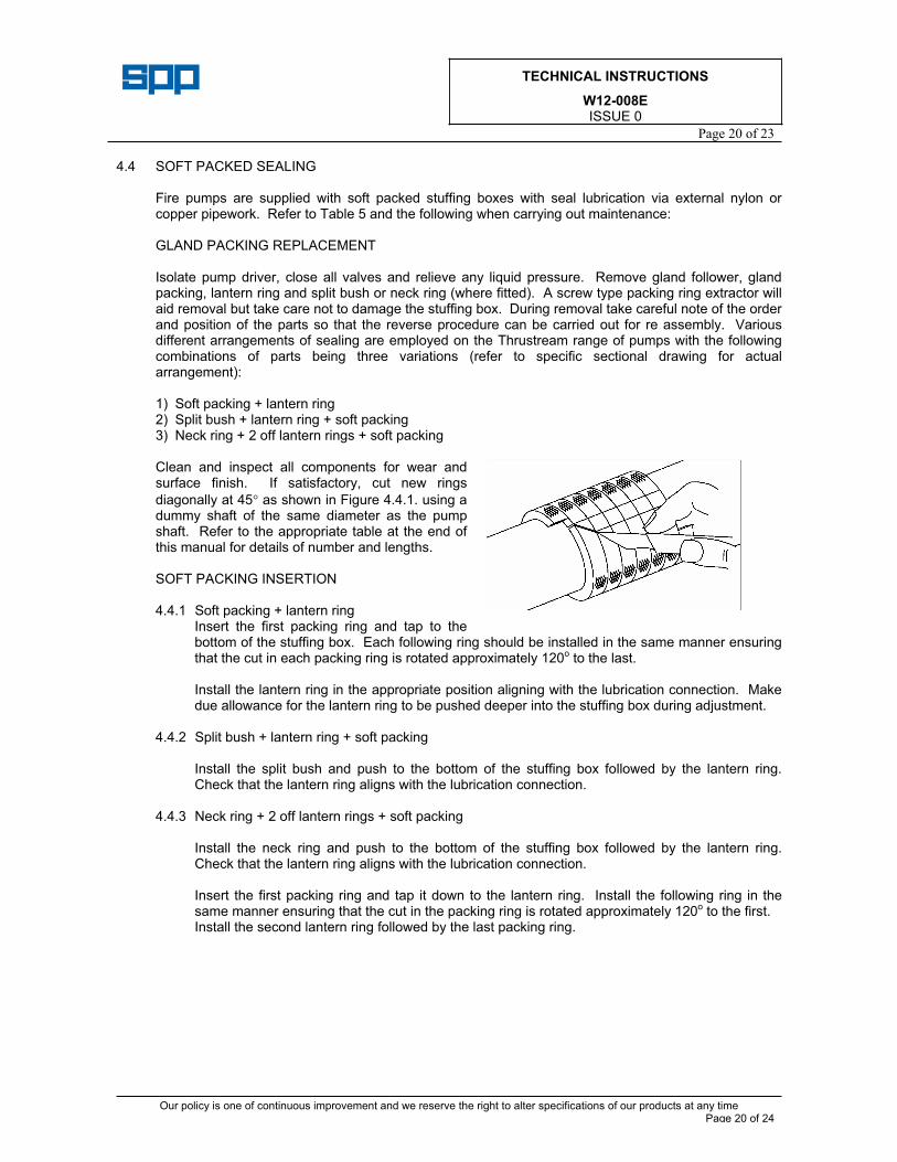
Clean and inspect all components for wear and surface finish. If satisfactory, cut new rings
diagonally at 45 as shown in Figure 4.4.1. using a dummy shaft of the same diameter as the pump shaft. Refer to the appropriate table at the end of this manual for details of number and lengths.
SOFT PACKING INSERTION
4.4.1 Soft packing + lantern ring Insert the first packing ring and tap to the bottom of the stuffing box. Each following ring should be installed in the same manner ensuring that the cut in each packing ring is rotated approximately 120o to the last.
Install the lantern ring in the appropriate position aligning with the lubrication connection. Make due allowance for the lantern ring to be pushed deeper into the stuffing box during adjustment.
4.4.2 Split bush + lantern ring + soft packing
Install the split bush and push to the bottom of the stuffing box followed by the lantern ring. Check that the lantern ring aligns with the lubrication connection.
4.4.3 Neck ring + 2 off lantern rings + soft packing
Install the neck ring and push to the bottom of the stuffing box followed by the lantern ring. Check that the lantern ring aligns with the lubrication connection.
Insert the first packing ring and tap it down to the lantern ring. Install the following ring in the same manner ensuring that the cut in the packing ring is rotated approximately 120o to the first. Install the second lantern ring followed by the last packing ring.
TECHNICAL INSTRUCTIONS
W12-008EISSUE 0
Page 21 of 23
Our policy is one of continuous improvement and we reserve the right to alter specifications of our products at any time Page 21 of 24
FINAL RE ASSEMBLY
The last packing ring should never protrude beyond the stuffing box face thus allowing the gland follower to 'start' in the stuffing box. If this is not the case, then dismantle and check that the correct numbers of rings have been used and that they have seated correctly.
Bring the gland follower up squarely against the last packing ring and finger-tighten the securing nuts evenly.
Turn the shaft to ensure that no binding is taking place.
Pressurise the stuffing box, ensuring there is no trapped air. The gland should start to leak heavily almost immediately. If it does not, stop the pump immediately and investigate.
GLAND FOLLOWER ADJUSTMENT
After the pump has been running for 10 minutes at full pressure, adjust the follower nuts by one sixth of a turn every 10 minutes until there is a small leakage only. This leakage is essential to ensure packing is lubricated.
4.5 MECHANICAL SEALS 4.5
In the case of pumps fitted with mechanical seals no specific routine maintenance is required. Where major overhaul is required contact SPP PUMPS INC SERVICE at the address shown in Section1.5
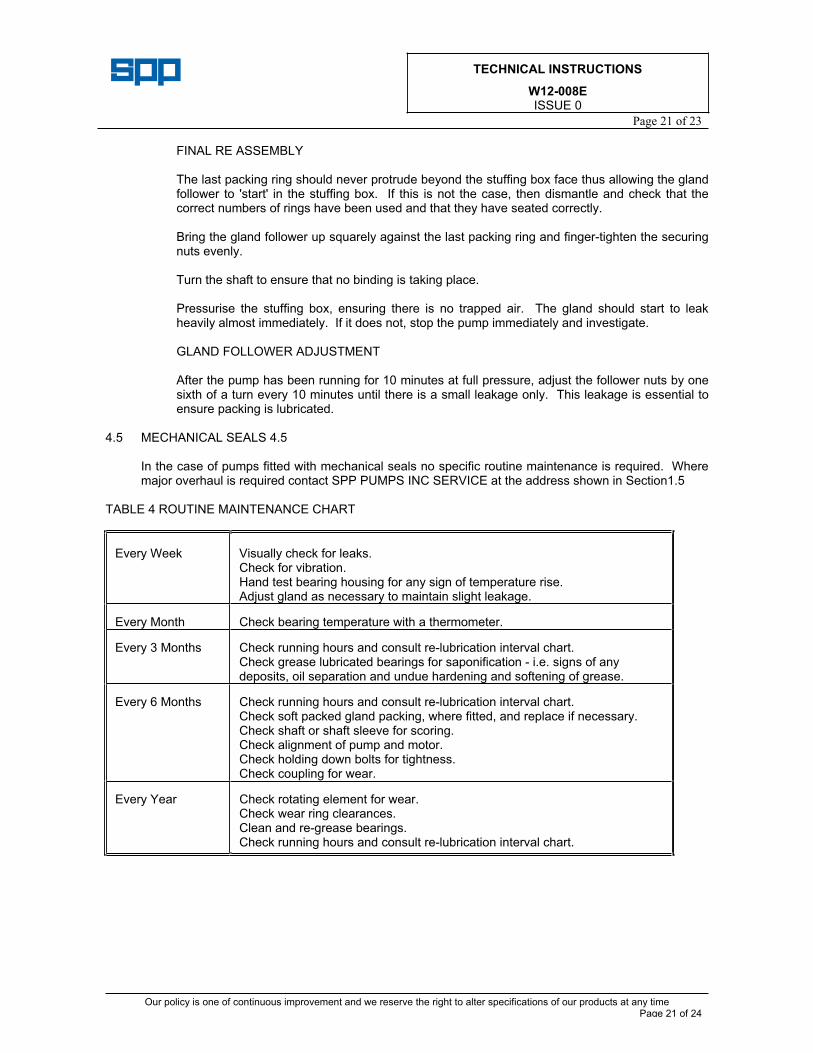
TABLE 4 ROUTINE MAINTENANCE CHART
Every Week Visually check for leaks. Check for vibration. Hand test bearing housing for any sign of temperature rise. Adjust gland as necessary to maintain slight leakage.
Every Month Check bearing temperature with a thermometer.
Every 3 Months Check running hours and consult re-lubrication interval chart. Check grease lubricated bearings for saponification - i.e. signs of any deposits, oil separation and undue hardening and softening of grease.
Every 6 Months Check running hours and consult re-lubrication interval chart. Check soft packed gland packing, where fitted, and replace if necessary. Check shaft or shaft sleeve for scoring. Check alignment of pump and motor. Check holding down bolts for tightness. Check coupling for wear.
Every Year Check rotating element for wear. Check wear ring clearances. Clean and re-grease bearings. Check running hours and consult re-lubrication interval chart.
TECHNICAL INSTRUCTIONS
W12-008EISSUE 0
Page 22 of 23
Our policy is one of continuous improvement and we reserve the right to alter specifications of our products at any time Page 22 of 24
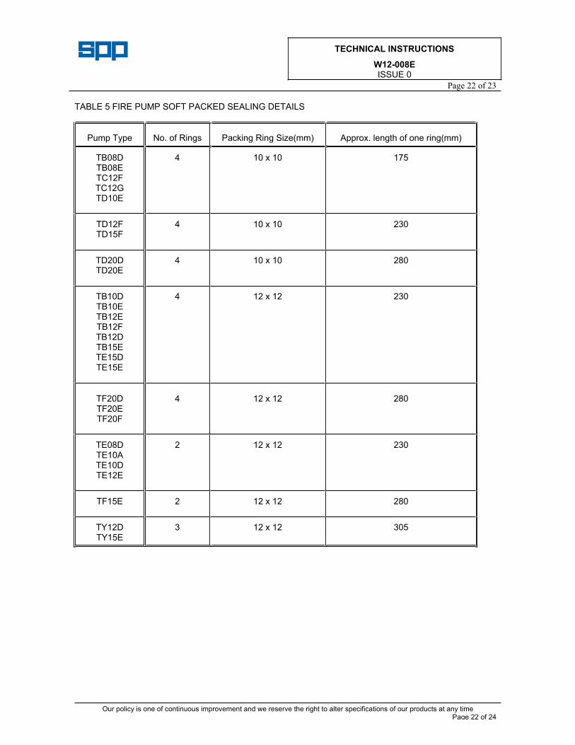
TABLE 5 FIRE PUMP SOFT PACKED SEALING DETAILS
Pump Type No. of Rings Packing Ring Size(mm) Approx. length of one ring(mm)
TB08D TB08ETC12FTC12GTD10E
4 10 x 10 175
TD12FTD15F
4 10 x 10 230
TD20D TD20E
4 10 x 10 280
TB10D TB10ETB12ETB12FTB12D TB15ETE15D TE15E
4 12 x 12 230
TF20DTF20ETF20F
4 12 x 12 280
TE08D TE10ATE10D TE12E
2 12 x 12 230
TF15E 2 12 x 12 280
TY12D TY15E
3 12 x 12 305
TECHNICAL INSTRUCTIONS
W12-008EISSUE 0
Page 23 of 23
Our policy is one of continuous improvement and we reserve the right to alter specifications of our products at any time. Page 23 of 23
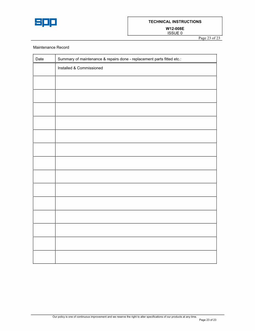
Maintenance Record
Date Summary of maintenance & repairs done - replacement parts fitted etc.:
Installed & Commissioned