manual de instalación, operación y mantenimiento ufb en_esp... · debe llenar un informe de...
TRANSCRIPT
1
Manual de Instalación, Operación y MantenimientoLea y guarde estas instrucciones para referencia futura. Lea detenidamente antes de ensamblar, instalar, operar o dar mantenimiento al producto que se describe. Por su propia seguridad y la de aquellos que lo rodean, preste atención a toda la información de seguridad. Si no respeta las instrucciones, puede provocar lesiones corporales o daños a la propiedad.
Ventilador Centrifugo de Utilidad
Documento 479718Modelo UFB
Ventilador Centrifugo de UtilidadUnidades de Ventilación Industrial
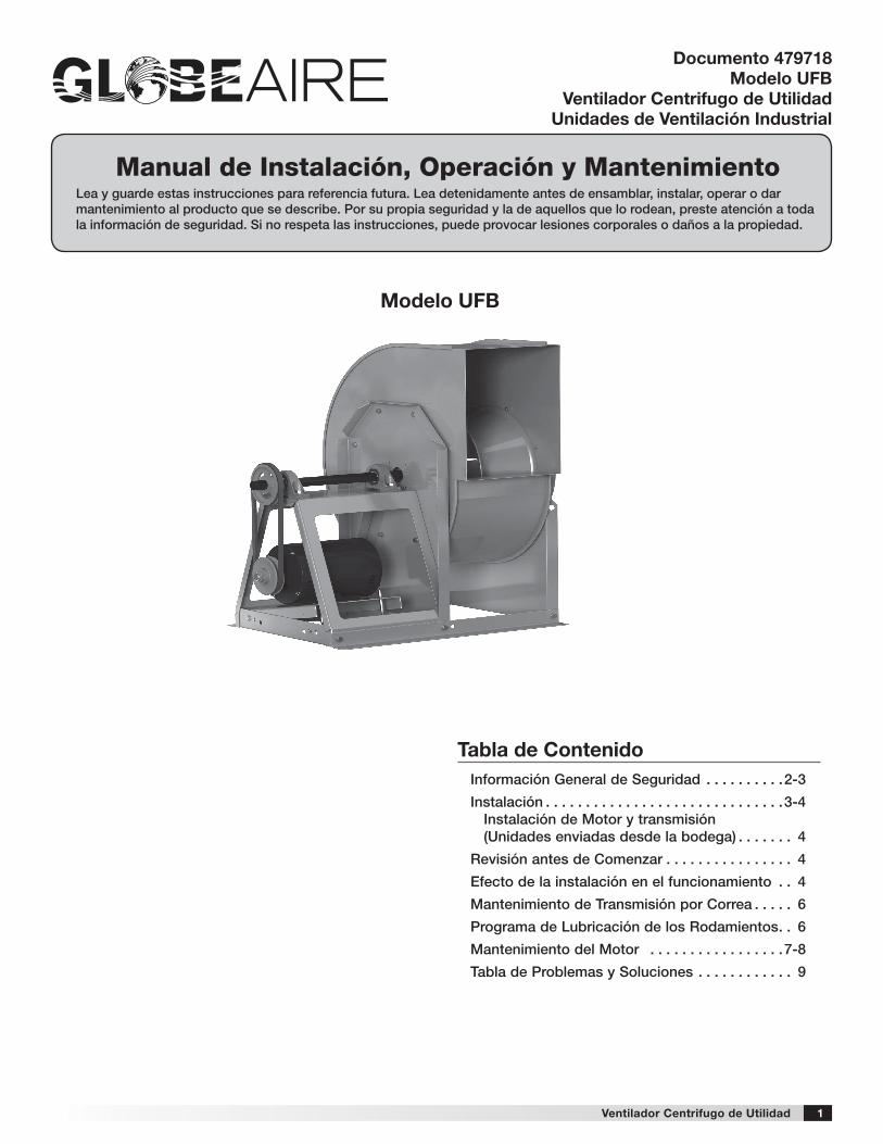
Modelo UFB
Tabla de ContenidoInformación General de Seguridad . . . . . . . . . .2-3
Instalación . . . . . . . . . . . . . . . . . . . . . . . . . . . . . .3-4 Instalación de Motor y transmisión (Unidades enviadas desde la bodega) . . . . . . . 4
Revisión antes de Comenzar . . . . . . . . . . . . . . . . 4
Efecto de la instalación en el funcionamiento . . 4
Mantenimiento de Transmisión por Correa . . . . . 6
Programa de Lubricación de los Rodamientos . . 6
Mantenimiento del Motor . . . . . . . . . . . . . . . . .7-8
Tabla de Problemas y Soluciones . . . . . . . . . . . . 9
2 Ventilador Centrifugo de Utilidad
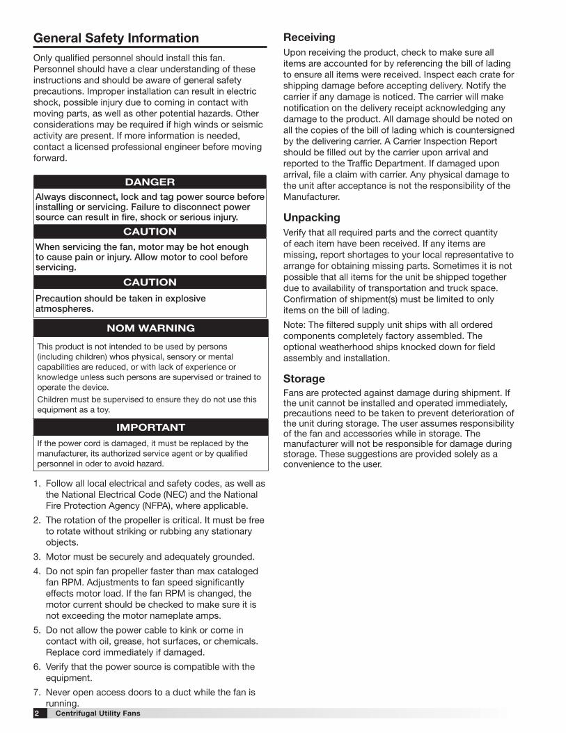
Información General De SeguridadSólo personal calificado debe instalar este ventilador. El personal debe tener una clara comprensión de estas instrucciones y debe ser consciente de las precauciones generales de seguridad. Una instalación inadecuada puede resultar en una descarga eléctrica, lesiones debido al entrar en contacto con las partes, así como otros peligros potenciales en movimiento. Otras consideraciones pueden ser necesarias si hay actividad sísmica. Si necesita más información, póngase en contacto con un ingeniero profesional con licencia antes de seguir adelante.
1. Siga todos los códigos eléctricos locales y deseguridad, así como el código eléctrico nacional(NEC) y la Agencia Nacional de protección deincendios (NFPA), en donde sea aplicable.
2. La rotación de la rueda es esencial. Debe estar libreal girar sin golpear o frotar objetos estacionarios.
3. El motor debe estar firmemente y adecuadamenteconectado a tierra.
4. No exceda las RPM de velocidad catalogada.Los ajustes de velocidad del motor tienen efectossignificativos a la carga del motor. Si se cambianlas RPM la corriente del motor debe medirse para
RecepciónAl recibir el producto, revíselo para asegurarse de que estén todos los artículos usando el conocimiento de embarque, para garantizar que se recibieron todos los artículos. Revise todas las cajas para ver si han sufrido daños en el transporte antes de aceptar la entrega. Infórmele al transportista si encuentra daños. El transportista pondrá una notificación en el recibo de entrega, reconociendo cualquier daño al producto. Todos los daños se deben anotar en todas las copias del conocimiento de embarque, el que es refrendado por el transportista que hizo la entrega. El transportista debe llenar un Informe de inspección del transportista en la entrega y se le debe informar al Departamento de Tránsito. Si el producto sufre daños al llegar, presente una queja al transportista. Cualquier daño físico que sufra la unidad después de la aceptación no es responsabilidad del fabricante.
DesembalajeCompruebe si recibió todas las partes necesarias y que estén en sus cantidades correctas. Si falta algún artículo, infórmelo a su representante local para organizar la obtención de las partes faltantes. Algunas veces no es posible enviar todos los artículos juntos a causa de la disponibilidad de transporte y el espacio en el transporte. Las confirmaciones de envío se deben limitar sólo a los artículos que se encuentran en el conocimiento de embarque.
Nota: La unidad con filtros es enviada con todos los componentes ensamblados en fábrica. Las otras cubiertas opcionales son enviadas para ser ensambladas e instaladas en el campo.
AlmacenamientoLos ventiladores están protegidos contra daños durante el envío. Si no se puede instalar y utilizar de forma inmediata, se deben tomar precauciones para prevenir el deterioro de la unidad durante su almacenamiento. El usuario es responsable del ventilador y sus accesorios durante su almacenamiento. El fabricante no se hace responsable por los daños que ocurran durante el almacenamiento. Estas sugerencias se entregan únicamente para comodidad del usuario.
PELIGROSiempre desconecte, bloque y etiquete la fuente de alimentación eléctrica antes de instalar o dar servicio . Si no desconecta la fuente de alimentación eléctrica puede ocasionar incendios, descargas o lesiones graves .
ADVERTENCIACuando se repare el ventilador, el motor puede estar lo suficientemente caliente como para causar una lesión . Permita que el motor se enfríe antes de darle servicio .
ADVERTENCIADebe tenerse precaución en atmósferas explosivas .
ADVERTENCIA DE NOM
Este aparato no se destina para utilizarse por personas (incluyendo niños) cuyas capacidades físicas, sensoriales o mentales, sean diferentes o estén reducidas, o carezcande experiencia o conocimiento, a menos que dichaspersonas reciban una supervisión o capacitación para elfuncionamiento del aparato por una persona responsable desu seguridad.
Los niños deben supervisarse para asegurar que ellos no
empleen los apratos como juguete.
IMPORTANTE
Si el cordón de alimentación es dañado, este debe sustituirse por el fabricante, por su agente de servicio autorizado o por personal calificado con el fin de evitar un peligro.
asegurarse de que no exceda los amperios de la placa del motor.
5. No permita que el cable de alimentación seenrosque o entre en contacto con aceite, grasa,superficies calientes o sustancias químicas.Reemplace el cable inmediatamente si está dañado.
6. Verifique que la fuente de alimentación escompatible con el equipo.
7. Nunca abra las puertas de acceso a un ductomientras está funcionando el ventilador.
3Ventilador Centrifugo de Utilidad
INTERIOR
El ambiente ideal para el almacenamiento de los ventiladores es en interiores, suspendidos, con una atmósfera de baja humedad que esté sellada para prevenir la entrada de polvo, lluvia o nieve. Las temperaturas se deben mantener de manera uniforme entre -1º C y 43º C (30° F y 110° F), las grandes oscilaciones de temperatura pueden producir condensación y “sudor” en las partes metálicas. Todos los accesorios deben estar almacenados al interior, en una atmósfera limpia y seca.
Elimine cualquier acumulación de suciedad, agua, hielo o nieve y seque las piezas antes de trasladarse al interior. Para evitar “sudor” de piezas metálicas, deje que las piezas alcancen la temperatura ambiente. Para secar las piezas y paquetes, utilice un calentador eléctrico portátil para deshacerse de cualquier acumulación de humedad. Afloje la cubierta del embalaje o revestimientos para permitir la circulación de aire y para permitir una inspección periódica.
La unidad debe estar almacenada suspendida al menos 8,9 cm (3,5 pulg.) con bloques de madera envueltos con papel antihumedad o cubiertas de polietileno. Deben quedar corredores entre las partes y por los muros para permitir la circulación del aire y dar espacio para las inspecciones.
EXTERIOR
Si fuese absolutamente necesario, los ventiladores diseñados para aplicaciones al aire libre se pueden almacenar en el exterior. Se necesitan calzas y corredores para los brazos de soporte y los equipos de arrastre.
El ventilador se debe colocar sobre una superficie nivelada para evitar que el agua se filtre al ventilador. Se debe elevar el ventilador a una altura adecuada con bloques de madera, para que quede sobre los niveles de agua y nieve. Ubique las partes lo suficientemente separadas para permitir la circulación del aire, luz y espacio para inspecciones periódicas. Para minimizar la acumulación de agua, coloque todas las partes del ventilador sobre los soportes para que el agua escurra.
No cubra las partes con plástico ni lonas, dado que éstas generan condensación de humedad del aire que pasa por los ciclos de calentamiento y de enfriamiento. Se deben fijar las hélices del ventilador para evitar que giren debido a los vientos fuertes.
Inspección y Mantenimiento durante el AlmacenamientoInspeccione los ventiladores una vez al mes durante su almacenamiento. Mantenga un registro de las inspecciones y mantenimientos que se lleven a cabo.
Si se encuentra humedad o acumulaciones de suciedad en las partes, se debe ubicar la fuente y eliminarla. En cada inspección, gire la hélice manualmente unas diez a quince revoluciones para distribuir el lubricante en el motor. Cada tres meses el motor deber ser encendido. Si la pintura se empieza a deteriorar, considera un retoque o reparación.
Las partes revestidas con antioxidante se deben restaurar a su condición adecuada si aparecen señales de oxidación. Elimine inmediatamente el revestimiento antioxidante original con solvente de petróleo y limpie con paños que no suelten pelusas. Pula todo el óxido restante de la superficie. No arruine la continuidad de las superficies. Limpie completamente con Tectyl® 506 (Ashland Inc.) o el equivalente. Para las superficies internas que son difíciles de alcanzar o para el uso ocasional, considere usar antioxidante Tectyl® 511M antioxidante, WD-40® o el equivalente.
Retiro del AlmacenamientoCuando los ventiladores son retirados de los almacenes para ser instalados en su ubicación final, deben ser protegidos y mantenidos en una manera similar hasta que el ventilador entre en operación.
4 Ventilador Centrifugo de Utilidad
CORRECTO
CORRECTO
INCORRECTO
INCORRECTO
INCORRECTO
INCORRECTO
JUSTO
JUSTO
JUSTO
CORRECTOINCORRECTO
INCORRECTO INCORRECTO
JUSTO
JUSTO
7o MAX.
1 Diámetro
de Hélice
Debe ser al menos1/2 diámetro de hélice
No mayor a unÁngulo de 60º
DirecciónVariada
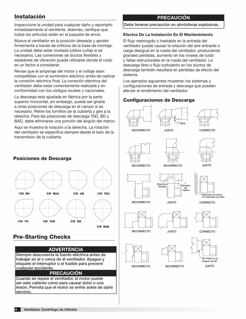
Configuraciones de Descarga
Efectos De La Instalación En El Mantenimiento
El flujo restringido o inestable en la entrada del ventilador puede causar la rotación del aire entrante o carga desigual en la rueda del ventilador, produciendo grandes pérdidas, aumento en los niveles de ruido y fallas estructurales en la rueda del ventilador. La descarga libre o flujo turbulento en los ductos de descarga también resultará en pérdidas de efecto del sistema.
Los ejemplos siguientes muestran los sistemas y configuraciones de entrada y descarga que pueden afectar el rendimiento del ventilador.
InstalaciónInspeccione la unidad para cualquier daño y reportarlo inmediatamente al remitente. Además, verifique que todos los artículos estén en el paquete de envío.
Mueva el ventilador en la posición deseada y apriete firmemente a través de orificios de la base de montaje. La unidad debe estar nivelada (utilice cuñas si es necesario). Las conexiones de ductos flexibles y aisladores de vibración puede utilizarse donde el ruido es un factor a considerar.
Revise que el amperaje del motor y el voltaje sean compatibles con el suministro eléctrico antes de realizar la conexión eléctrica final. La conexión eléctrica del ventilador debe estar correctamente realizada y en conformidad con los códigos locales y nacionales.
La descarga esta ajustada en fábrica por la parte superior horizontal, sin embargo, puede ser girada a otras posiciones de descarga en el campo si es necesario. Retire los tornillos de la cubierta y gire a la derecha. Para las posiciones de descarga TAD, BD y BAD, debe eliminarse una porción del ángulo del marco.
Aquí se muestra la rotación a la derecha. La rotación del ventilador se especifica siempre desde el lado de la transmisión de la cubierta.
CW BH CW BAU CW TAUCW UB
CW TH CW TAD
CW BAD
CW DB
Posiciones de Descarga
Pre-Starting Checks
ADVERTENCIASiempre desconecta la fuente eléctrica antes de trabajar en el o cerca de el ventilador . Apague y etiquete el interruptor o el fusible para prevenir cualquier accidente .
PRECAUCIÓNCuando se repare el ventilador, el motor puede ser este caliente como para causar dolor o una lesión . Permita que el motor se enfríe antes de darle servicio .
PRECAUCIÓNDebe tenerse precaución en atmósferas explosivas .
5Ventilador Centrifugo de Utilidad
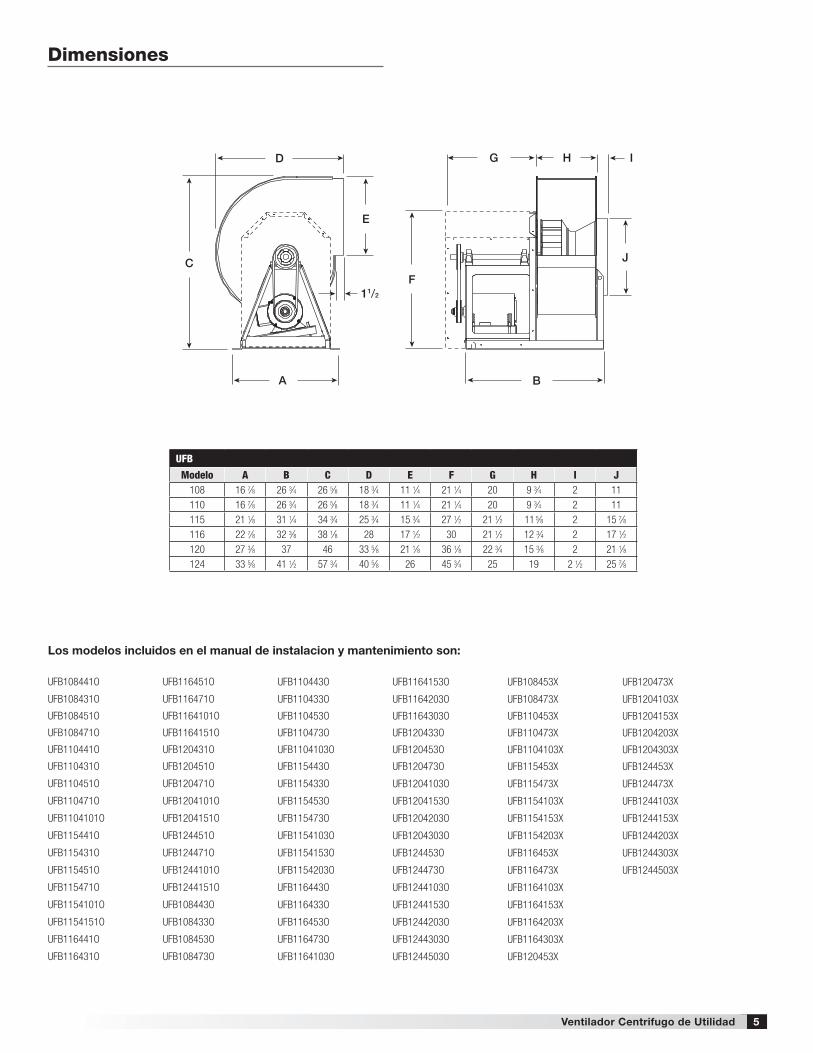
Dimensiones
D
C
A B
F
G H I
J
E
11/2
UFB
Modelo A B C D E F G H I J108 16 7⁄8 26 3⁄4 26 5⁄8 18 3⁄4 11 1⁄4 21 1⁄4 20 9 3⁄4 2 11110 16 7⁄8 26 3⁄4 26 5⁄8 18 3⁄4 11 1⁄4 21 1⁄4 20 9 3⁄4 2 11115 21 1⁄8 31 1⁄4 34 3⁄4 25 3⁄4 15 3⁄4 27 1⁄2 21 1⁄2 11 5⁄8 2 15 7⁄8116 22 7⁄8 32 3⁄8 38 1⁄8 28 17 1⁄2 30 21 1⁄2 12 3⁄4 2 17 1⁄2120 27 3⁄8 37 46 33 5⁄8 21 1⁄8 36 1⁄8 22 3⁄4 15 3⁄8 2 21 1⁄8124 33 5⁄8 41 1⁄2 57 3⁄4 40 5⁄8 26 45 3⁄4 25 19 2 1⁄2 25 7⁄8
Los modelos incluidos en el manual de instalacion y mantenimiento son:
UFB108441O
UFB108431O
UFB108451O
UFB108471O
UFB110441O
UFB110431O
UFB110451O
UFB110471O
UFB1104101O
UFB115441O
UFB115431O
UFB115451O
UFB115471O
UFB1154101O
UFB1154151O
UFB116441O
UFB116431O
UFB116451O
UFB116471O
UFB1164101O
UFB1164151O
UFB120431O
UFB120451O
UFB120471O
UFB1204101O
UFB1204151O
UFB124451O
UFB124471O
UFB1244101O
UFB1244151O
UFB108443O
UFB108433O
UFB108453O
UFB108473O
UFB110443O
UFB110433O
UFB110453O
UFB110473O
UFB1104103O
UFB115443O
UFB115433O
UFB115453O
UFB115473O
UFB1154103O
UFB1154153O
UFB1154203O
UFB116443O
UFB116433O
UFB116453O
UFB116473O
UFB1164103O
UFB1164153O
UFB1164203O
UFB1164303O
UFB120433O
UFB120453O
UFB120473O
UFB1204103O
UFB1204153O
UFB1204203O
UFB1204303O
UFB124453O
UFB124473O
UFB1244103O
UFB1244153O
UFB1244203O
UFB1244303O
UFB1244503O
UFB108453X
UFB108473X
UFB110453X
UFB110473X
UFB1104103X
UFB115453X
UFB115473X
UFB1154103X
UFB1154153X
UFB1154203X
UFB116453X
UFB116473X
UFB1164103X
UFB1164153X
UFB1164203X
UFB1164303X
UFB120453X
UFB120473X
UFB1204103X
UFB1204153X
UFB1204203X
UFB1204303X
UFB124453X
UFB124473X
UFB1244103X
UFB1244153X
UFB1244203X
UFB1244303X
UFB1244503X
6 Ventilador Centrifugo de Utilidad
Inclinada Hacia Atrás
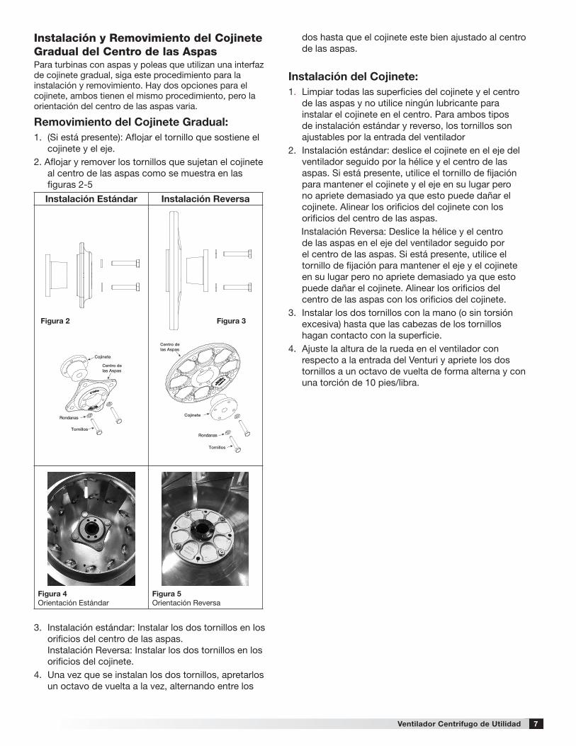
RuedasLas ruedas deben girar libremente y asegúrese que no rocen con el venturi de la entrada. La rueda del modelo UFB se traslapa en el venturi de entrada como se muestra en la figura 1.
Modelo UFBFig . 1
Gap
Wheel
EspacioRadial
Traslape
Rueda
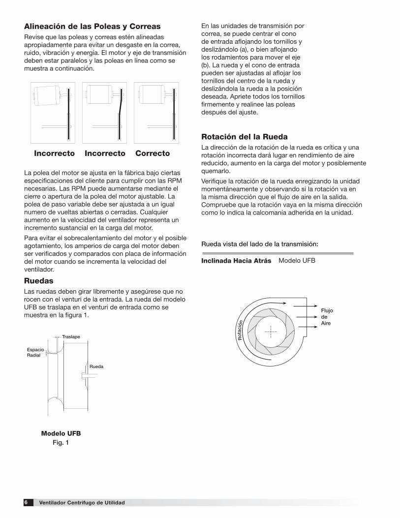
Alineación de las Poleas y CorreasRevise que las poleas y correas estén alineadas apropiadamente para evitar un desgaste en la correa, ruido, vibración y energía. El motor y eje de transmisión deben estar paralelos y las poleas en línea como se muestra a continuación.
La polea del motor se ajusta en la fábrica bajo ciertas especificaciones del cliente para cumplir con las RPM necesarias. Las RPM puede aumentarse mediante el cierre o apertura de la polea del motor ajustable. La polea de paso variable debe ser ajustada a un igual numero de vueltas abiertas o cerradas. Cualquier aumento en la velocidad del ventilador representa un incremento sustancial en la carga del motor.
Para evitar el sobrecalentamiento del motor y el posible agotamiento, los amperios de carga del motor deben ser verificados y comparados con placa de información del motor cuando se incrementa la velocidad del ventilador.
Incorrecto Incorrecto Correcto
Rotación del la RuedaLa dirección de la rotación de la rueda es crítica y una rotación incorrecta dará lugar en rendimiento de aire reducido, aumento en la carga del motor y posiblemente quemarlo.
Verifique la rotación de la rueda enregizando la unidad momentáneamente y observando si la rotación va en la misma dirección que el flujo de aire en la salida. Compruebe que la rotación vaya en la misma dirección como lo indica la calcomanía adherida en la unidad.
En las unidades de transmisión por correa, se puede centrar el cono de entrada aflojando los tornillos y deslizándolo (a), o bien aflojando los rodamientos para mover el eje (b). La rueda y el cono de entrada pueden ser ajustadas al aflojar los tornillos del centro de la rueda y deslizándola la rueda a la posición deseada. Apriete todos los tornillos firmemente y realinee las poleas después del ajuste.
Ro
tation
Ro
tatio
n
Rotation
Rotation
Backward Inclined
Forward Curved
Airflow
Airflow
Backward Inclined Forward Curved
FlujodeAire
Airflow
Airfoil
These are the original drawings on the Illustrator filewhen I opened it. The IOM had the wheel layered on top of the scroll.I will incorporate the wheel on the scrollwithout creatingan additional layer in the InDesign file.
April 19, 2011
I positioned the wheels onto the scroll outline. The forward curved wheel was mirrored and positioned on the scroll above. This is how was done in the InDesign Utility Fans IOM file.The wheel was laid on top of the scroll within the InDesign file. Better to do this within Illustrator.
barb w
Ro
tatio
n
Ro
tation
Rot
ació
n Airflow
Airfoil
Rueda vista del lado de la transmisión:
Modelo UFB
7Ventilador Centrifugo de Utilidad
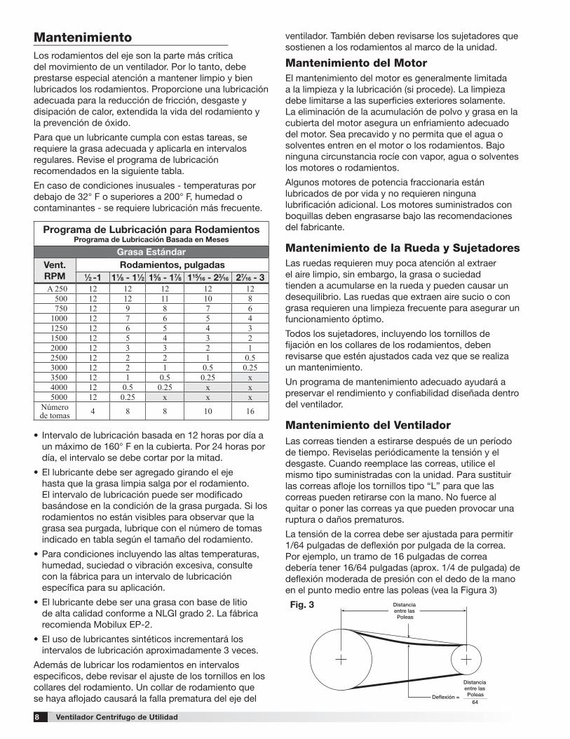
Instalación y Removimiento del Cojinete Gradual del Centro de las AspasPara turbinas con aspas y poleas que utilizan una interfaz de cojinete gradual, siga este procedimiento para la instalación y removimiento. Hay dos opciones para el cojinete, ambos tienen el mismo procedimiento, pero la orientación del centro de las aspas varia.
Removimiento del Cojinete Gradual:1. (Si está presente): Aflojar el tornillo que sostiene el
cojinete y el eje.2. Aflojar y remover los tornillos que sujetan el cojinete
al centro de las aspas como se muestra en lasfiguras 2-5
3. Instalación estándar: Instalar los dos tornillos en losorificios del centro de las aspas.Instalación Reversa: Instalar los dos tornillos en losorificios del cojinete.
4. Una vez que se instalan los dos tornillos, apretarlosun octavo de vuelta a la vez, alternando entre los
Instalación Estándar Instalación Reversa
Figura 4 Orientación Estándar
Figura 5Orientación Reversa
Figura 2 Figura 3
Cojinete
Cojinete
Rondanas
Rondanas
Tornillos
Tornillos
Centro de las Aspas
Centro de las Aspas
Cojinete
Cojinete
Rondanas
Rondanas
Tornillos
Tornillos
Centro de las Aspas
Centro de las Aspas
dos hasta que el cojinete este bien ajustado al centro de las aspas.
Instalación del Cojinete:1. Limpiar todas las superficies del cojinete y el centro
de las aspas y no utilice ningún lubricante parainstalar el cojinete en el centro. Para ambos tiposde instalación estándar y reverso, los tornillos sonajustables por la entrada del ventilador
2. Instalación estándar: deslice el cojinete en el eje delventilador seguido por la hélice y el centro de lasaspas. Si está presente, utilice el tornillo de fijaciónpara mantener el cojinete y el eje en su lugar perono apriete demasiado ya que esto puede dañar elcojinete. Alinear los orificios del cojinete con losorificios del centro de las aspas.Instalación Reversa: Deslice la hélice y el centrode las aspas en el eje del ventilador seguido porel centro de las aspas. Si está presente, utilice eltornillo de fijación para mantener el eje y el cojineteen su lugar pero no apriete demasiado ya que estopuede dañar el cojinete. Alinear los orificios delcentro de las aspas con los orificios del cojinete.
3. Instalar los dos tornillos con la mano (o sin torsiónexcesiva) hasta que las cabezas de los tornilloshagan contacto con la superficie.
4. Ajuste la altura de la rueda en el ventilador conrespecto a la entrada del Venturi y apriete los dostornillos a un octavo de vuelta de forma alterna y conuna torción de 10 pies/libra.
8
Deflexión = 64
Distancia entre las Poleas
Distancia entre las Poleas
Fig. 3
ventilador. También deben revisarse los sujetadores que sostienen a los rodamientos al marco de la unidad.
Mantenimiento del Motor El mantenimiento del motor es generalmente limitada a la limpieza y la lubricación (si procede). La limpieza debe limitarse a las superficies exteriores solamente. La eliminación de la acumulación de polvo y grasa en la cubierta del motor asegura un enfriamiento adecuado del motor. Sea precavido y no permita que el agua o solventes entren en el motor o los rodamientos. Bajo ninguna circunstancia rocíe con vapor, agua o solventes los motores o rodamientos.
Algunos motores de potencia fraccionaria están lubricados de por vida y no requieren ninguna lubrificación adicional. Los motores suministrados con boquillas deben engrasarse bajo las recomendaciones del fabricante.
Mantenimiento de la Rueda y SujetadoresLas ruedas requieren muy poca atención al extraer el aire limpio, sin embargo, la grasa o suciedad tienden a acumularse en la rueda y pueden causar un desequilibrio. Las ruedas que extraen aire sucio o con grasa requieren una limpieza frecuente para asegurar un funcionamiento óptimo.
Todos los sujetadores, incluyendo los tornillos de fijación en los collares de los rodamientos, deben revisarse que estén ajustados cada vez que se realiza un mantenimiento.
Un programa de mantenimiento adecuado ayudará a preservar el rendimiento y confiabilidad diseñada dentro del ventilador.
Mantenimiento del VentiladorLas correas tienden a estirarse después de un período de tiempo. Reviselas periódicamente la tensión y el desgaste. Cuando reemplace las correas, utilice el mismo tipo suministradas con la unidad. Para sustituir las correas afloje los tornillos tipo “L” para que las correas pueden retirarse con la mano. No fuerce al quitar o poner las correas ya que pueden provocar una ruptura o daños prematuros.
La tensión de la correa debe ser ajustada para permitir 1/64 pulgadas de deflexión por pulgada de la correa. Por ejemplo, un tramo de 16 pulgadas de correa debería tener 16/64 pulgadas (aprox. 1/4 de pulgada) de deflexión moderada de presión con el dedo de la mano en el punto medio entre las poleas (vea la Figura 3)
Los rodamientos del eje son la parte más crítica del movimiento de un ventilador. Por lo tanto, debe prestarse especial atención a mantener limpio y bien lubricados los rodamientos. Proporcione una lubricación adecuada para la reducción de fricción, desgaste y disipación de calor, extendida la vida del rodamiento y la prevención de óxido.
Para que un lubricante cumpla con estas tareas, se requiere la grasa adecuada y aplicarla en intervalos regulares. Revise el programa de lubricación recomendados en la siguiente tabla.
En caso de condiciones inusuales - temperaturas por debajo de 32° F o superiores a 200° F, humedad o contaminantes - se requiere lubricación más frecuente.
• Intervalo de lubricación basada en 12 horas por día aun máximo de 160° F en la cubierta. Por 24 horas pordía, el intervalo se debe cortar por la mitad.
• El lubricante debe ser agregado girando el ejehasta que la grasa limpia salga por el rodamiento.El intervalo de lubricación puede ser modificadobasándose en la condición de la grasa purgada. Si losrodamientos no están visibles para observar que lagrasa sea purgada, lubrique con el número de tomasindicado en tabla según el tamaño del rodamiento.
• Para condiciones incluyendo las altas temperaturas,humedad, suciedad o vibración excesiva, consultecon la fábrica para un intervalo de lubricaciónespecífica para su aplicación.
• El lubricante debe ser una grasa con base de litiode alta calidad conforme a NLGI grado 2. La fábricarecomienda Mobilux EP-2.
• El uso de lubricantes sintéticos incrementará losintervalos de lubricación aproximadamente 3 veces.
Además de lubricar los rodamientos en intervalos especificos, debe revisar el ajuste de los tornillos en los collares del rodamiento. Un collar de rodamiento que se haya aflojado causará la falla prematura del eje del
Programa de Lubricación para RodamientosPrograma de Lubricación Basada en Meses
Grasa EstándarVent. RPM
Rodamientos, pulgadas 1⁄2 -1 11⁄8 - 11⁄2 15⁄8 - 17⁄8 115⁄16 - 23⁄16 27⁄16 - 3
A 250 12 12 12 12 12500 12 12 11 10 8750 12 9 8 7 6
1000 12 7 6 5 41250 12 6 5 4 31500 12 5 4 3 22000 12 3 3 2 12500 12 2 2 1 0.53000 12 2 1 0.5 0.253500 12 1 0.5 0.25 x4000 12 0.5 0.25 x x5000 12 0.25 x x x
Númerode tomas 4 8 8 10 16
Mantenimiento
Ventilador Centrifugo de Utilidad
9
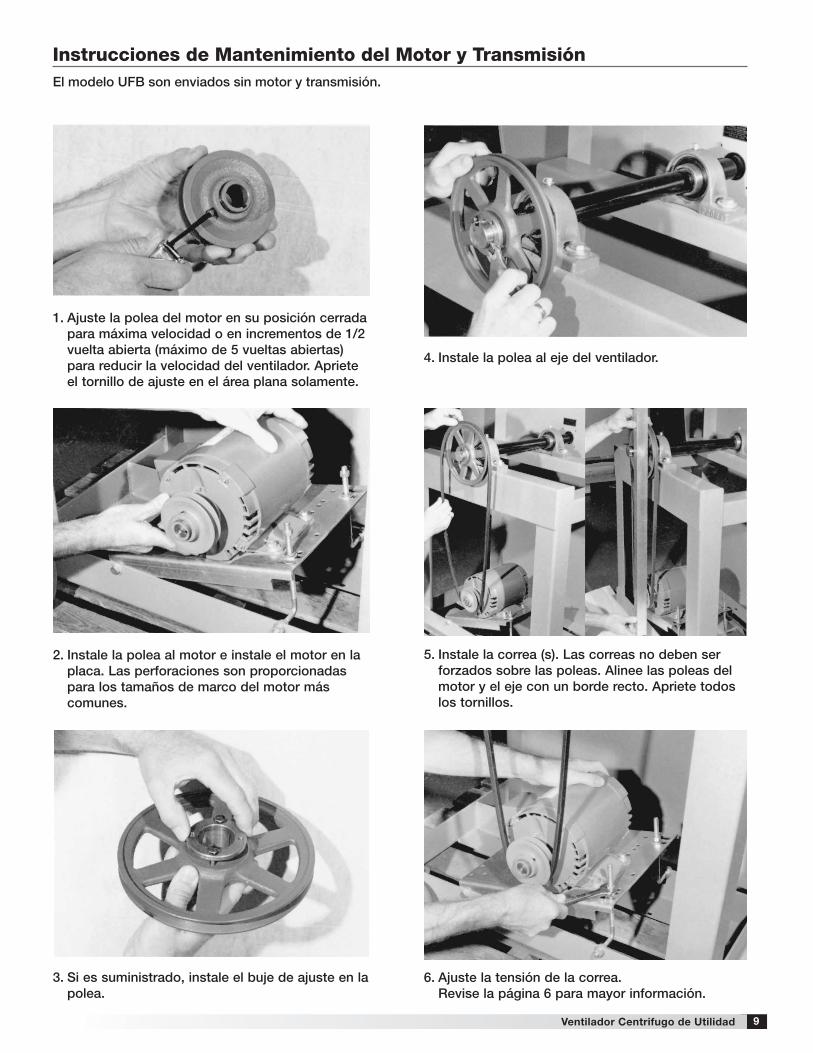
Instrucciones de Mantenimiento del Motor y TransmisiónEl modelo UFB son enviados sin motor y transmisión .
1 . Ajuste la polea del motor en su posición cerrada para máxima velocidad o en incrementos de 1/2 vuelta abierta (máximo de 5 vueltas abiertas) para reducir la velocidad del ventilador . Apriete el tornillo de ajuste en el área plana solamente .
4 . Instale la polea al eje del ventilador .
5 . Instale la correa (s) . Las correas no deben ser forzados sobre las poleas . Alinee las poleas del motor y el eje con un borde recto . Apriete todos los tornillos .
6 . Ajuste la tensión de la correa . Revise la página 6 para mayor información .
2 . Instale la polea al motor e instale el motor en la placa . Las perforaciones son proporcionadas para los tamaños de marco del motor más comunes .
3 . Si es suministrado, instale el buje de ajuste en la polea .
Ventilador Centrifugo de Utilidad
La publicación AMCA 410-96, Prácticas de seguridad para usuarios y personal de instalación de ventiladores industriales y comerciales, proporciona información de seguridad adicional. Esta publicación se puede obtener en AMCA International, Inc, en: www.amca.org.
Los catálogos de Extractores Centrífugos para Plafón y Extractores de Gabinete de Globeaire proporciona información adicional que describe el equipo, el funcionamiento del extractor, los accesorios disponibles y datos de la especificación.
10
[email protected] • globeaire.com
479718 • UFB, Rev. 1, julio 2016 Copyright 2016 © Globeaire
Como resultado de nuestra comisión de mejora continua, Globeaire reserva el derecho de cambiar especificaciones sin aviso.
Nuestro Compromiso
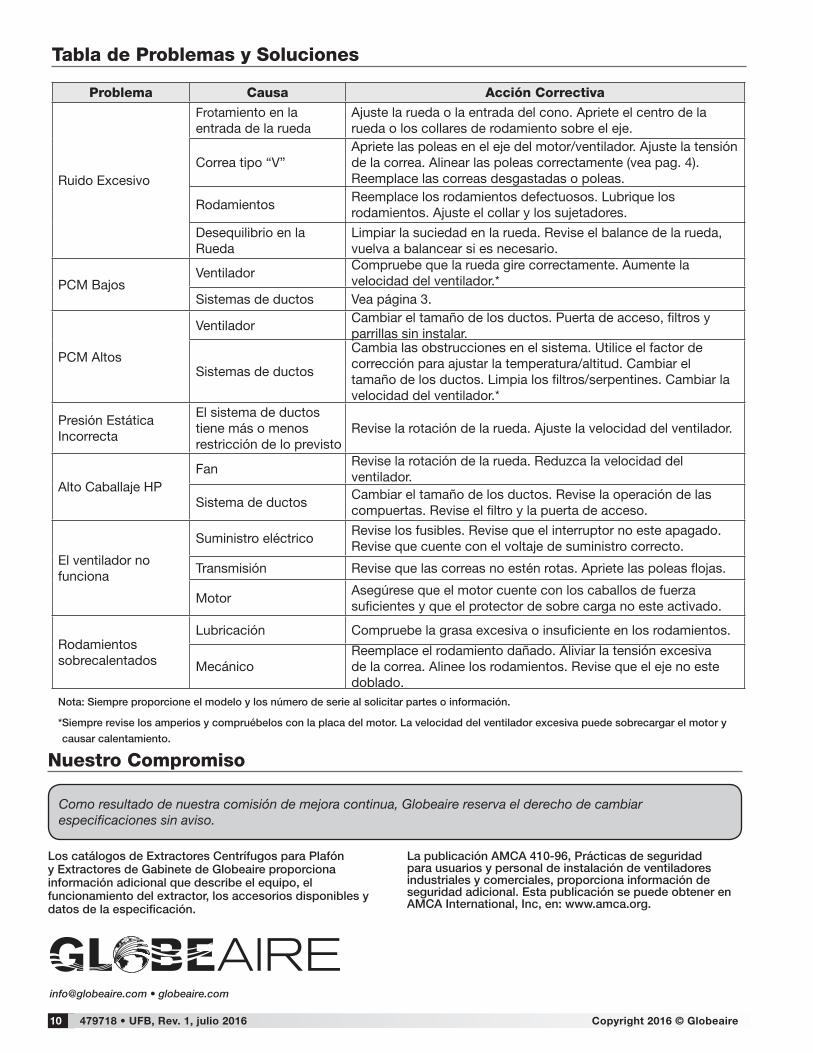
Tabla de Problemas y Soluciones
Problema Causa Acción Correctiva
Ruido Excesivo
Frotamiento en la entrada de la rueda
Ajuste la rueda o la entrada del cono. Apriete el centro de la rueda o los collares de rodamiento sobre el eje.
Correa tipo “V”Apriete las poleas en el eje del motor/ventilador. Ajuste la tensión de la correa. Alinear las poleas correctamente (vea pag. 4). Reemplace las correas desgastadas o poleas.
RodamientosReemplace los rodamientos defectuosos. Lubrique los rodamientos. Ajuste el collar y los sujetadores.
Desequilibrio en la Rueda
Limpiar la suciedad en la rueda. Revise el balance de la rueda, vuelva a balancear si es necesario.
PCM BajosVentilador
Compruebe que la rueda gire correctamente. Aumente la velocidad del ventilador.*
Sistemas de ductos Vea página 3.
PCM Altos
VentiladorCambiar el tamaño de los ductos. Puerta de acceso, filtros y parrillas sin instalar.
Sistemas de ductos
Cambia las obstrucciones en el sistema. Utilice el factor de corrección para ajustar la temperatura/altitud. Cambiar el tamaño de los ductos. Limpia los filtros/serpentines. Cambiar la velocidad del ventilador.*
Presión Estática Incorrecta
El sistema de ductos tiene más o menos restricción de lo previsto
Revise la rotación de la rueda. Ajuste la velocidad del ventilador.
Alto Caballaje HPFan
Revise la rotación de la rueda. Reduzca la velocidad del ventilador.
Sistema de ductosCambiar el tamaño de los ductos. Revise la operación de las compuertas. Revise el filtro y la puerta de acceso.
El ventilador no funciona
Suministro eléctricoRevise los fusibles. Revise que el interruptor no este apagado. Revise que cuente con el voltaje de suministro correcto.
Transmisión Revise que las correas no estén rotas. Apriete las poleas flojas.
MotorAsegúrese que el motor cuente con los caballos de fuerza suficientes y que el protector de sobre carga no este activado.
Rodamientos sobrecalentados
Lubricación Compruebe la grasa excesiva o insuficiente en los rodamientos.
MecánicoReemplace el rodamiento dañado. Aliviar la tensión excesiva de la correa. Alinee los rodamientos. Revise que el eje no este doblado.
Nota: Siempre proporcione el modelo y los número de serie al solicitar partes o información .
* Siempre revise los amperios y compruébelos con la placa del motor . La velocidad del ventilador excesiva puede sobrecargar el motor y
causar calentamiento .
1
Installation, Operation and Maintenance ManualPlease read and save these instructions for future reference. Read carefully before attempting to assemble, install, operate or maintain the product described. Protect yourself and others by observing all safety information. Failure to comply with instructions could result in personal injury and/or property damage!
Centrifugal Utility Fans
Document 479718Model UFB
Centrifugal Utility FansIndustrial Ventilation Units
Model UFB
Table of ContentsGeneral Safety Information . . . . . . . . . . . . . . . . .2-3
Installation . . . . . . . . . . . . . . . . . . . . . . . . . . . . . .3-4 Motor and Drive Installation (Units Shipped from Stock) . . . . . . . . . . . . . . . . 4
Pre-Starting Checks . . . . . . . . . . . . . . . . . . . . . . . 4
Affect of Installation on Performance . . . . . . . . . 4
Belt Drive Fan Maintenance . . . . . . . . . . . . . . . . . 6
Bearing Lubrication Schedule . . . . . . . . . . . . . . . 6
Motor Maintenance . . . . . . . . . . . . . . . . . . . . . .7-8
Troubleshooting Chart . . . . . . . . . . . . . . . . . . . . . 9
2 Centrifugal Utility Fans
Only qualified personnel should install this fan. Personnel should have a clear understanding of these instructions and should be aware of general safety precautions. Improper installation can result in electric shock, possible injury due to coming in contact with moving parts, as well as other potential hazards. Other considerations may be required if high winds or seismic activity are present. If more information is needed, contact a licensed professional engineer before moving forward.
1. Follow all local electrical and safety codes, as well as the National Electrical Code (NEC) and the National Fire Protection Agency (NFPA), where applicable.
2. The rotation of the propeller is critical. It must be free to rotate without striking or rubbing any stationary objects.
3. Motor must be securely and adequately grounded.
4. Do not spin fan propeller faster than max cataloged fan RPM. Adjustments to fan speed significantly effects motor load. If the fan RPM is changed, the motor current should be checked to make sure it is not exceeding the motor nameplate amps.
5. Do not allow the power cable to kink or come in contact with oil, grease, hot surfaces, or chemicals. Replace cord immediately if damaged.
6. Verify that the power source is compatible with the equipment.
7. Never open access doors to a duct while the fan is running.
General Safety Information
DANGERAlways disconnect, lock and tag power source before installing or servicing . Failure to disconnect power source can result in fire, shock or serious injury .
CAUTION
When servicing the fan, motor may be hot enough to cause pain or injury . Allow motor to cool before servicing .
CAUTION
Precaution should be taken in explosive atmospheres .
ReceivingUpon receiving the product, check to make sure all items are accounted for by referencing the bill of lading to ensure all items were received. Inspect each crate for shipping damage before accepting delivery. Notify the carrier if any damage is noticed. The carrier will make notification on the delivery receipt acknowledging any damage to the product. All damage should be noted on all the copies of the bill of lading which is countersigned by the delivering carrier. A Carrier Inspection Report should be filled out by the carrier upon arrival and reported to the Traffic Department. If damaged upon arrival, file a claim with carrier. Any physical damage to the unit after acceptance is not the responsibility of the Manufacturer.
UnpackingVerify that all required parts and the correct quantity of each item have been received. If any items are missing, report shortages to your local representative to arrange for obtaining missing parts. Sometimes it is not possible that all items for the unit be shipped together due to availability of transportation and truck space. Confirmation of shipment(s) must be limited to only items on the bill of lading.
Note: The filtered supply unit ships with all ordered components completely factory assembled. The optional weatherhood ships knocked down for field assembly and installation.
StorageFans are protected against damage during shipment. If the unit cannot be installed and operated immediately, precautions need to be taken to prevent deterioration of the unit during storage. The user assumes responsibility of the fan and accessories while in storage. The manufacturer will not be responsible for damage during storage. These suggestions are provided solely as a convenience to the user.
NOM WARNING
This product is not intended to be used by persons (including children) whos physical, sensory or mental capabilities are reduced, or with lack of experience or knowledge unless such persons are supervised or trained to operate the device.
Children must be supervised to ensure they do not use this equipment as a toy.
IMPORTANT
If the power cord is damaged, it must be replaced by the manufacturer, its authorized service agent or by qualified personnel in oder to avoid hazard.
3Centrifugal Utility Fans
INDOOR
The ideal environment for the storage of fans and accessories is indoors, above grade, in a low humidity atmosphere which is sealed to prevent the entry of blowing dust, rain or snow. Temperatures should be evenly maintained between 30° to 110°F (-1° to 43°C), wide temperature swings may cause condensation and “sweating” of metal parts. All accessories must be stored indoors in a clean, dry atmosphere.
Remove any accumulations of dirt, water, ice, or snow and wipe dry before moving to indoor storage. To avoid “sweating” of metal parts allow cold parts to reach room temperature. To dry parts and packages use a portable electric heater to remove any moisture build up. Leave coverings loose to permit air circulation and to allow for periodic inspection.
The unit should be stored at least 3½ inches (89 mm) off the floor on wooden blocks covered with moisture proof paper or polyethylene sheathing. Aisles between parts and along all walls should be provided to permit air circulation and space for inspection.
OUTDOOR
Fans designed for outdoor applications may be stored outdoors, if absolutely necessary. Roads or aisles for portable cranes and hauling equipment are needed.
The fan should be placed on a level surface to prevent water from leaking into the fan. The fan should be elevated on an adequate number of wooden blocks so it is above water and snow levels and has enough blocking to prevent it from settling into soft ground. Locate parts far enough apart to permit air circulation, sunlight and space for periodic inspection. To minimize water accumulation, place all fan parts on blocking supports so rain water will run off.
Do not cover parts with plastic film or tarps as these cause condensation of moisture from the air passing through heating and cooling cycles. Fan wheels should be blocked to prevent spinning caused by strong winds.
Inspection and Maintenance During StorageWhile in storage, inspect fans once per month. Keep a record of inspection and maintenance performed.
If moisture or dirt accumulations are found on parts, the source should be located and eliminated. At each inspection, rotate the wheel by hand ten to fifteen revolutions to distribute lubricant on motor. If paint deterioration begins, consideration should be given to touch-up or repainting. Fans with special coatings may require special techniques for touch-up or repair.
Machined parts coated with rust preventive should be restored to good condition promptly if signs of rust occur. Immediately remove the original rust preventive coating with petroleum solvent and clean with lint-free cloths. Polish any remaining rust from surface with crocus cloth or fine emery paper and oil. Do not destroy the continuity of the surfaces. Thoroughly wipe clean with Tectyl® 506 (Ashland Inc.) or the equivalent. For hard to reach internal surfaces or for occasional use, consider using Tectyl® 511M Rust Preventive, WD-40® or the equivalent.
Removing From StorageAs fans are removed from storage to be installed in their final location, they should be protected and maintained in a similar fashion until the fan equipment goes into operation.
4 Centrifugal Utility Fans
GOODPOOR
POOR
FAIR
7o MAX.
POOR FAIR
POOR FAIR
One Impeller
Dia.
GOOD
Should be at least1/2 Impeller Dia.
FAIR
Not Greater than60o Including Angle
POOR
POOR FAIR GOOD
POOR
TurningVaries
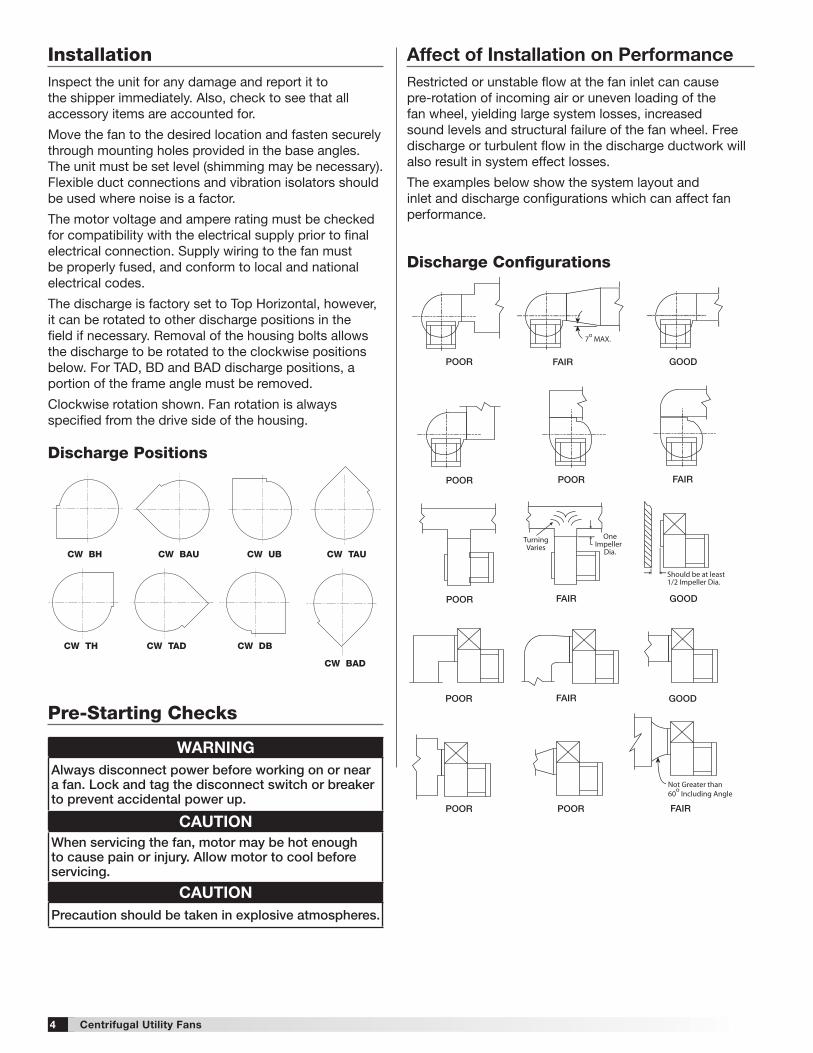
Discharge Configurations
Affect of Installation on PerformanceRestricted or unstable flow at the fan inlet can cause pre-rotation of incoming air or uneven loading of the fan wheel, yielding large system losses, increased sound levels and structural failure of the fan wheel. Free discharge or turbulent flow in the discharge ductwork will also result in system effect losses.
The examples below show the system layout and inlet and discharge configurations which can affect fan performance.
InstallationInspect the unit for any damage and report it to the shipper immediately. Also, check to see that all accessory items are accounted for.
Move the fan to the desired location and fasten securely through mounting holes provided in the base angles. The unit must be set level (shimming may be necessary). Flexible duct connections and vibration isolators should be used where noise is a factor.
The motor voltage and ampere rating must be checked for compatibility with the electrical supply prior to final electrical connection. Supply wiring to the fan must be properly fused, and conform to local and national electrical codes.
The discharge is factory set to Top Horizontal, however, it can be rotated to other discharge positions in the field if necessary. Removal of the housing bolts allows the discharge to be rotated to the clockwise positions below. For TAD, BD and BAD discharge positions, a portion of the frame angle must be removed.
Clockwise rotation shown. Fan rotation is always specified from the drive side of the housing.
CW BH CW BAU CW TAUCW UB
CW TH CW TAD
CW BAD
CW DB
Discharge Positions
Pre-Starting Checks
WARNINGAlways disconnect power before working on or near a fan . Lock and tag the disconnect switch or breaker to prevent accidental power up .
CAUTIONWhen servicing the fan, motor may be hot enough to cause pain or injury . Allow motor to cool before servicing .
CAUTIONPrecaution should be taken in explosive atmospheres .
5Centrifugal Utility Fans
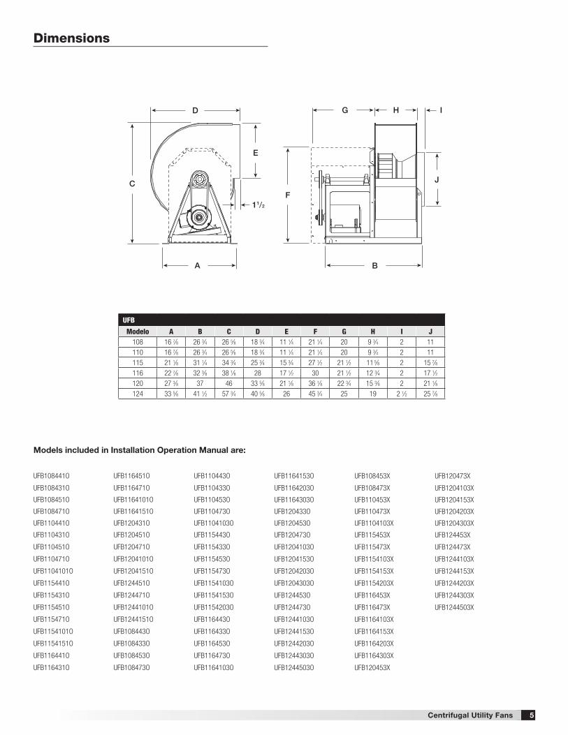
Dimensions
D
C
A B
F
G H I
J
E
11/2
UFB
Modelo A B C D E F G H I J108 16 7⁄8 26 3⁄4 26 5⁄8 18 3⁄4 11 1⁄4 21 1⁄4 20 9 3⁄4 2 11110 16 7⁄8 26 3⁄4 26 5⁄8 18 3⁄4 11 1⁄4 21 1⁄4 20 9 3⁄4 2 11115 21 1⁄8 31 1⁄4 34 3⁄4 25 3⁄4 15 3⁄4 27 1⁄2 21 1⁄2 11 5⁄8 2 15 7⁄8116 22 7⁄8 32 3⁄8 38 1⁄8 28 17 1⁄2 30 21 1⁄2 12 3⁄4 2 17 1⁄2120 27 3⁄8 37 46 33 5⁄8 21 1⁄8 36 1⁄8 22 3⁄4 15 3⁄8 2 21 1⁄8124 33 5⁄8 41 1⁄2 57 3⁄4 40 5⁄8 26 45 3⁄4 25 19 2 1⁄2 25 7⁄8
UFB108441O
UFB108431O
UFB108451O
UFB108471O
UFB110441O
UFB110431O
UFB110451O
UFB110471O
UFB1104101O
UFB115441O
UFB115431O
UFB115451O
UFB115471O
UFB1154101O
UFB1154151O
UFB116441O
UFB116431O
Models included in Installation Operation Manual are:
UFB116451O
UFB116471O
UFB1164101O
UFB1164151O
UFB120431O
UFB120451O
UFB120471O
UFB1204101O
UFB1204151O
UFB124451O
UFB124471O
UFB1244101O
UFB1244151O
UFB108443O
UFB108433O
UFB108453O
UFB108473O
UFB110443O
UFB110433O
UFB110453O
UFB110473O
UFB1104103O
UFB115443O
UFB115433O
UFB115453O
UFB115473O
UFB1154103O
UFB1154153O
UFB1154203O
UFB116443O
UFB116433O
UFB116453O
UFB116473O
UFB1164103O
UFB1164153O
UFB1164203O
UFB1164303O
UFB120433O
UFB120453O
UFB120473O
UFB1204103O
UFB1204153O
UFB1204203O
UFB1204303O
UFB124453O
UFB124473O
UFB1244103O
UFB1244153O
UFB1244203O
UFB1244303O
UFB1244503O
UFB108453X
UFB108473X
UFB110453X
UFB110473X
UFB1104103X
UFB115453X
UFB115473X
UFB1154103X
UFB1154153X
UFB1154203X
UFB116453X
UFB116473X
UFB1164103X
UFB1164153X
UFB1164203X
UFB1164303X
UFB120453X
UFB120473X
UFB1204103X
UFB1204153X
UFB1204203X
UFB1204303X
UFB124453X
UFB124473X
UFB1244103X
UFB1244153X
UFB1244203X
UFB1244303X
UFB1244503X
6 Centrifugal Utility Fans
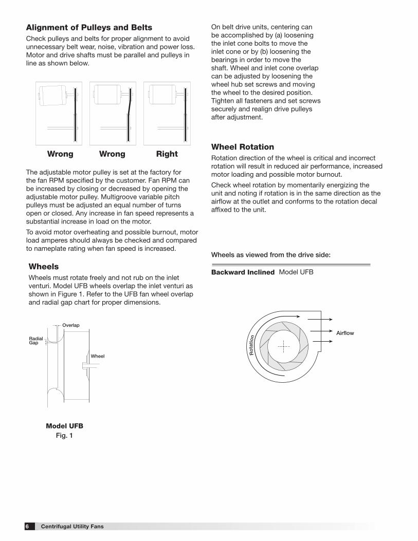
WheelsWheels must rotate freely and not rub on the inlet venturi. Model UFB wheels overlap the inlet venturi as shown in Figure 1. Refer to the UFB fan wheel overlap and radial gap chart for proper dimensions.
Model UFBFig . 1
Gap
Wheel
RadialGap
Overlap
Wheel
Alignment of Pulleys and BeltsCheck pulleys and belts for proper alignment to avoid unnecessary belt wear, noise, vibration and power loss. Motor and drive shafts must be parallel and pulleys in line as shown below.
The adjustable motor pulley is set at the factory for the fan RPM specified by the customer. Fan RPM can be increased by closing or decreased by opening the adjustable motor pulley. Multigroove variable pitch pulleys must be adjusted an equal number of turns open or closed. Any increase in fan speed represents a substantial increase in load on the motor.
To avoid motor overheating and possible burnout, motor load amperes should always be checked and compared to nameplate rating when fan speed is increased.
Wrong Wrong RightWheel RotationRotation direction of the wheel is critical and incorrect rotation will result in reduced air performance, increased motor loading and possible motor burnout.
Check wheel rotation by momentarily energizing the unit and noting if rotation is in the same direction as the airflow at the outlet and conforms to the rotation decal affixed to the unit.
On belt drive units, centering can be accomplished by (a) loosening the inlet cone bolts to move the inlet cone or by (b) loosening the bearings in order to move the shaft. Wheel and inlet cone overlap can be adjusted by loosening the wheel hub set screws and moving the wheel to the desired position. Tighten all fasteners and set screws securely and realign drive pulleys after adjustment.
Ro
tation
Ro
tatio
n
Rotation
Rotation
Backward Inclined
Forward Curved
Airflow
Airflow
Backward Inclined Forward Curved
Airflow
Airflow
These are the original drawings on the Illustrator filewhen I opened it. The IOM had the wheel layered on top of the scroll.I will incorporate the wheel on the scrollwithout creatingan additional layer in the InDesign file.
April 19, 2011
I positioned the wheels onto the scroll outline. The forward curved wheel was mirrored and positioned on the scroll above. This is how was done in the InDesign Utility Fans IOM file.The wheel was laid on top of the scroll within the InDesign file. Better to do this within Illustrator.
barb w
Ro
tatio
n
Ro
tation
Ro
tatio
n Airflow
Airfoil
Wheels as viewed from the drive side:
Backward Inclined Model UFB
7Centrifugal Utility Fans
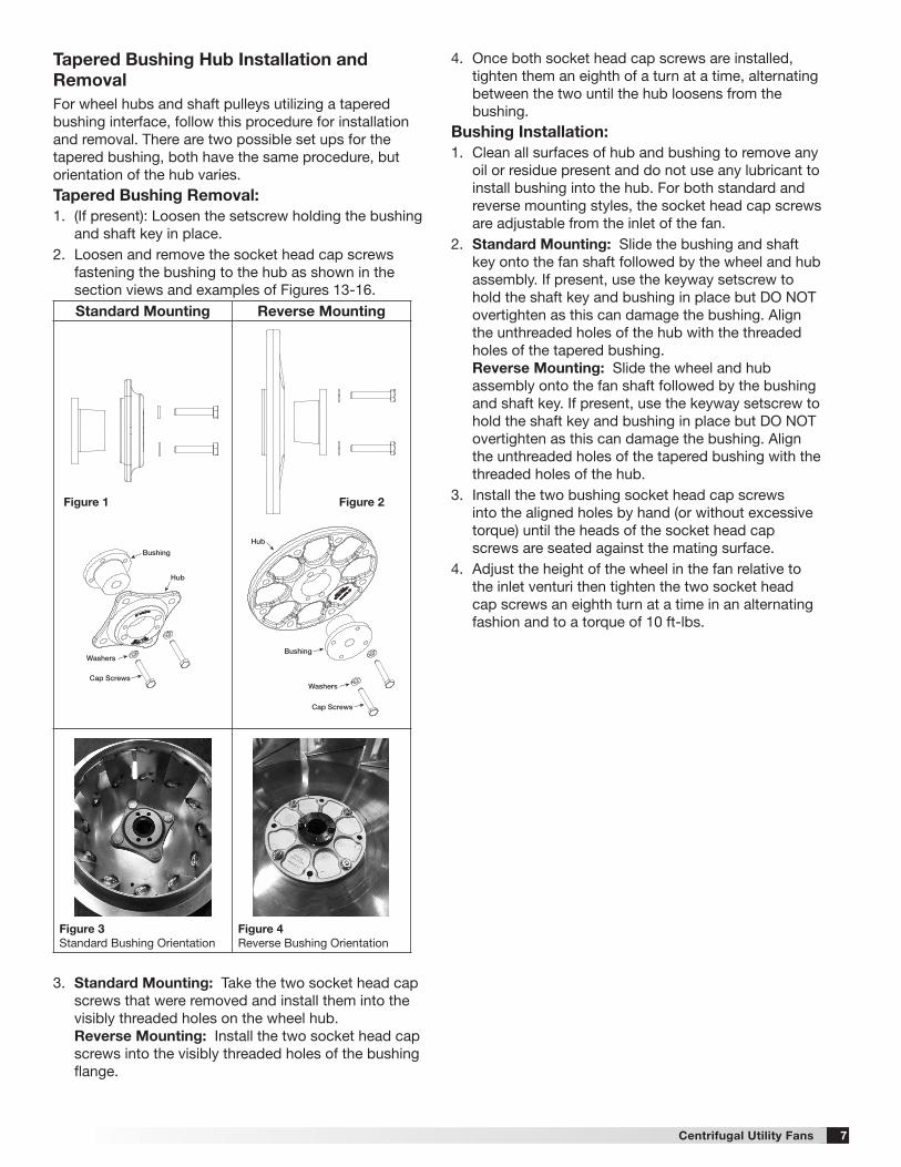
Tapered Bushing Hub Installation and RemovalFor wheel hubs and shaft pulleys utilizing a tapered bushing interface, follow this procedure for installation and removal. There are two possible set ups for the tapered bushing, both have the same procedure, but orientation of the hub varies.Tapered Bushing Removal:1. (If present): Loosen the setscrew holding the bushing
and shaft key in place.2. Loosen and remove the socket head cap screws
fastening the bushing to the hub as shown in the section views and examples of Figures 13-16.
3. Standard Mounting: Take the two socket head cap screws that were removed and install them into the visibly threaded holes on the wheel hub. Reverse Mounting: Install the two socket head cap screws into the visibly threaded holes of the bushing flange.
Standard Mounting Reverse Mounting
Figure 3 Standard Bushing Orientation
Figure 4Reverse Bushing Orientation
Figure 1 Figure 2
Bushing
Washers
Cap Screws
Hub
Bushing
Washers
Cap Screws
Hub
Bushing
Washers
Cap Screws
Hub
Bushing
Washers
Cap Screws
Hub
4. Once both socket head cap screws are installed, tighten them an eighth of a turn at a time, alternating between the two until the hub loosens from the bushing.
Bushing Installation:1. Clean all surfaces of hub and bushing to remove any
oil or residue present and do not use any lubricant to install bushing into the hub. For both standard and reverse mounting styles, the socket head cap screws are adjustable from the inlet of the fan.
2. Standard Mounting: Slide the bushing and shaft key onto the fan shaft followed by the wheel and hub assembly. If present, use the keyway setscrew to hold the shaft key and bushing in place but DO NOT overtighten as this can damage the bushing. Align the unthreaded holes of the hub with the threaded holes of the tapered bushing. Reverse Mounting: Slide the wheel and hub assembly onto the fan shaft followed by the bushing and shaft key. If present, use the keyway setscrew to hold the shaft key and bushing in place but DO NOT overtighten as this can damage the bushing. Align the unthreaded holes of the tapered bushing with the threaded holes of the hub.
3. Install the two bushing socket head cap screws into the aligned holes by hand (or without excessive torque) until the heads of the socket head cap screws are seated against the mating surface.
4. Adjust the height of the wheel in the fan relative to the inlet venturi then tighten the two socket head cap screws an eighth turn at a time in an alternating fashion and to a torque of 10 ft-lbs.
8
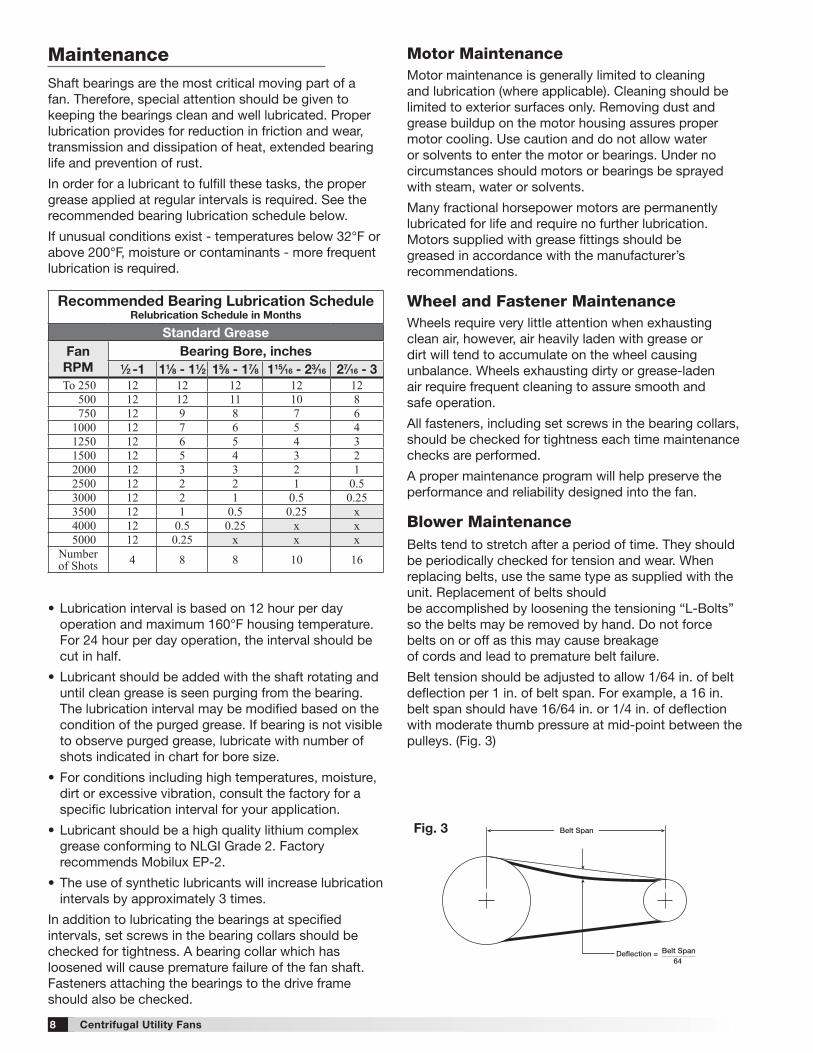
Shaft bearings are the most critical moving part of a fan. Therefore, special attention should be given to keeping the bearings clean and well lubricated. Proper lubrication provides for reduction in friction and wear, transmission and dissipation of heat, extended bearing life and prevention of rust.
In order for a lubricant to fulfill these tasks, the proper grease applied at regular intervals is required. See the recommended bearing lubrication schedule below.
If unusual conditions exist - temperatures below 32°F or above 200°F, moisture or contaminants - more frequent lubrication is required.
• Lubrication interval is based on 12 hour per day operation and maximum 160°F housing temperature. For 24 hour per day operation, the interval should be cut in half.
• Lubricant should be added with the shaft rotating and until clean grease is seen purging from the bearing. The lubrication interval may be modified based on the condition of the purged grease. If bearing is not visible to observe purged grease, lubricate with number of shots indicated in chart for bore size.
• For conditions including high temperatures, moisture, dirt or excessive vibration, consult the factory for a specific lubrication interval for your application.
• Lubricant should be a high quality lithium complex grease conforming to NLGI Grade 2. Factory recommends Mobilux EP-2.
• The use of synthetic lubricants will increase lubrication intervals by approximately 3 times.
In addition to lubricating the bearings at specified intervals, set screws in the bearing collars should be checked for tightness. A bearing collar which has loosened will cause premature failure of the fan shaft. Fasteners attaching the bearings to the drive frame should also be checked.
Deflection = Belt Span64
Belt SpanFig. 3
Motor Maintenance Motor maintenance is generally limited to cleaning and lubrication (where applicable). Cleaning should be limited to exterior surfaces only. Removing dust and grease buildup on the motor housing assures proper motor cooling. Use caution and do not allow water or solvents to enter the motor or bearings. Under no circumstances should motors or bearings be sprayed with steam, water or solvents.
Many fractional horsepower motors are permanently lubricated for life and require no further lubrication. Motors supplied with grease fittings should be greased in accordance with the manufacturer’s recommendations.
Wheel and Fastener MaintenanceWheels require very little attention when exhausting clean air, however, air heavily laden with grease or dirt will tend to accumulate on the wheel causing unbalance. Wheels exhausting dirty or grease-laden air require frequent cleaning to assure smooth and safe operation.
All fasteners, including set screws in the bearing collars, should be checked for tightness each time maintenance checks are performed.
A proper maintenance program will help preserve the performance and reliability designed into the fan.
Blower MaintenanceBelts tend to stretch after a period of time. They should be periodically checked for tension and wear. When replacing belts, use the same type as supplied with the unit. Replacement of belts should be accomplished by loosening the tensioning “L-Bolts” so the belts may be removed by hand. Do not force belts on or off as this may cause breakage of cords and lead to premature belt failure.
Belt tension should be adjusted to allow 1/64 in. of belt deflection per 1 in. of belt span. For example, a 16 in. belt span should have 16/64 in. or 1/4 in. of deflection with moderate thumb pressure at mid-point between the pulleys. (Fig. 3)
Recommended Bearing Lubrication ScheduleRelubrication Schedule in Months
Standard GreaseFan RPM
Bearing Bore, inches 1⁄2 -1 11⁄8 - 11⁄2 15⁄8 - 17⁄8 115⁄16 - 23⁄16 27⁄16 - 3
To 250 12 12 12 12 12500 12 12 11 10 8750 12 9 8 7 6
1000 12 7 6 5 41250 12 6 5 4 31500 12 5 4 3 22000 12 3 3 2 12500 12 2 2 1 0.53000 12 2 1 0.5 0.253500 12 1 0.5 0.25 x4000 12 0.5 0.25 x x5000 12 0.25 x x x
Numberof Shots 4 8 8 10 16
Maintenance
Centrifugal Utility Fans
9
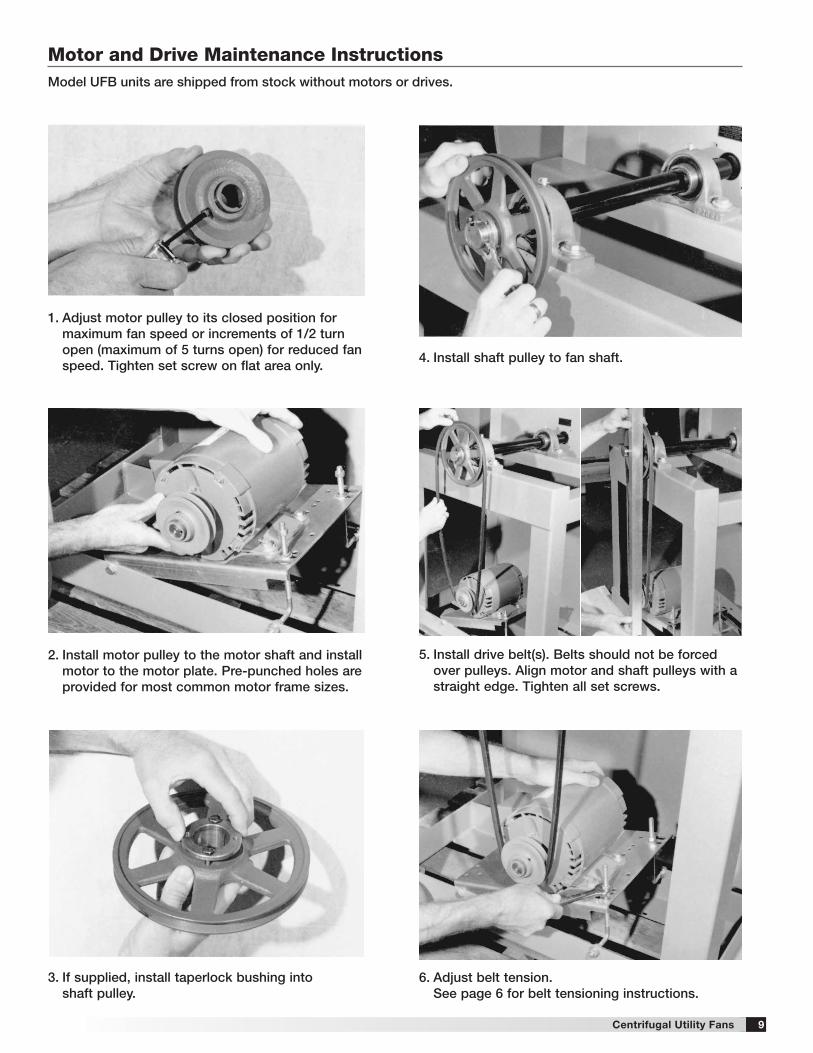
Motor and Drive Maintenance InstructionsModel UFB units are shipped from stock without motors or drives .
1 . Adjust motor pulley to its closed position for maximum fan speed or increments of 1/2 turn open (maximum of 5 turns open) for reduced fan speed . Tighten set screw on flat area only .
4 . Install shaft pulley to fan shaft .
5 . Install drive belt(s) . Belts should not be forced over pulleys . Align motor and shaft pulleys with a straight edge . Tighten all set screws .
6 . Adjust belt tension . See page 6 for belt tensioning instructions .
2 . Install motor pulley to the motor shaft and install motor to the motor plate . Pre-punched holes are provided for most common motor frame sizes .
3 . If supplied, install taperlock bushing into shaft pulley .
Centrifugal Utility Fans
[email protected] • globeaire.com
AMCA Publication 410-96, Safety Practices for Users and Installers of Industrial and Commercial Fans, provides additional safety information. This publication can be obtained from AMCA International, Inc. at: www.amca.org.
As a result of our commitment to continuous improvement, Globeaire reserves the right to change specifications without notice.
10
Our Commitment
479718 • UFB, Rev. 1, July 2016 Copyright 2016 © Globeaire
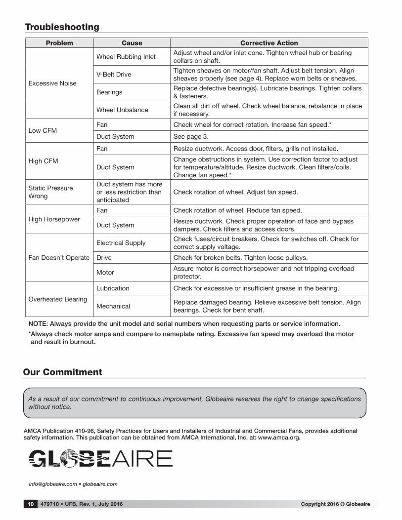
Problem Cause Corrective Action
Excessive Noise
Wheel Rubbing InletAdjust wheel and/or inlet cone. Tighten wheel hub or bearing collars on shaft.
V-Belt DriveTighten sheaves on motor/fan shaft. Adjust belt tension. Align sheaves properly (see page 4). Replace worn belts or sheaves.
BearingsReplace defective bearing(s). Lubricate bearings. Tighten collars & fasteners.
Wheel UnbalanceClean all dirt off wheel. Check wheel balance, rebalance in place if necessary.
Low CFMFan Check wheel for correct rotation. Increase fan speed.*
Duct System See page 3.
High CFM
Fan Resize ductwork. Access door, filters, grills not installed.
Duct SystemChange obstructions in system. Use correction factor to adjust for temperature/altitude. Resize ductwork. Clean filters/coils. Change fan speed.*
Static Pressure Wrong
Duct system has more or less restriction than anticipated
Check rotation of wheel. Adjust fan speed.
High HorsepowerFan Check rotation of wheel. Reduce fan speed.
Duct SystemResize ductwork. Check proper operation of face and bypass dampers. Check filters and access doors.
Fan Doesn’t Operate
Electrical SupplyCheck fuses/circuit breakers. Check for switches off. Check for correct supply voltage.
Drive Check for broken belts. Tighten loose pulleys.
MotorAssure motor is correct horsepower and not tripping overload protector.
Overheated Bearing
Lubrication Check for excessive or insufficient grease in the bearing.
MechanicalReplace damaged bearing. Relieve excessive belt tension. Align bearings. Check for bent shaft.
NOTE: Always provide the unit model and serial numbers when requesting parts or service information .
* Always check motor amps and compare to nameplate rating . Excessive fan speed may overload the motor and result in burnout .
Troubleshooting