manual bomba a diafragma wilden modelo p400
DESCRIPTION
Manual completo de instalación, mantenimiento y despiece de bombas a difragma marca Wilden modelo P400TRANSCRIPT
P400/PV400
TT4871 5/05 5M EOM P400P/PV400P 6/05Replaces P400P 7/03
EOM
A d v a n c e y o u r p r o c e s s
E n g i n e e r i n gO p e r a t i o n &M a i n t e n a n c eAdvanced™ Series PLASTIC Pumps
T A B L E O F C O N T E N T S
SECTION 1 CAUTIONS—READ FIRST! . . . . . . . . . . . . . . . . . . . . . . . . . . . . . . . . . . . . . . . . . . . . . .1
SECTION 2 WILDEN PUMP DESIGNATION SYSTEM . . . . . . . . . . . . . . . . . . . . . . . . . . . . . . . . .2
SECTION 3 HOW IT WORKS—PUMP & AIR DISTRIBUTION SYSTEM . . . . . . . . . . . . . . . .3
SECTION 4 DIMENSIONAL DRAWINGS . . . . . . . . . . . . . . . . . . . . . . . . . . . . . . . . . . . . . . . . . . . . .4
SECTION 5 PERFORMANCEA. P400 Performance Curves
Rubber-Fitted . . . . . . . . . . . . . . . . . . . . . . . . . . . . . . . . . . . . . . . . . . . . . . . . . . . . . . . .5
TPE-Fitted . . . . . . . . . . . . . . . . . . . . . . . . . . . . . . . . . . . . . . . . . . . . . . . . . . . . . . . . . . .5
PTFE-Fitted . . . . . . . . . . . . . . . . . . . . . . . . . . . . . . . . . . . . . . . . . . . . . . . . . . . . . . . . . .6
PV400 Performance Curves
Rubber-Fitted . . . . . . . . . . . . . . . . . . . . . . . . . . . . . . . . . . . . . . . . . . . . . . . . . . . . . . . .7
TPE-Fitted . . . . . . . . . . . . . . . . . . . . . . . . . . . . . . . . . . . . . . . . . . . . . . . . . . . . . . . . . . .7
PTFE-Fitted . . . . . . . . . . . . . . . . . . . . . . . . . . . . . . . . . . . . . . . . . . . . . . . . . . . . . . . . . .8
B. Suction Lift Curves . . . . . . . . . . . . . . . . . . . . . . . . . . . . . . . . . . . . . . . . . . . . . . . . . . . . .9
SECTION 6 SUGGESTED INSTALLATION, OPERATION & TROUBLESHOOTING . . . . . . . 10
SECTION 7 ASSEMBLY / DISASSEMBLY . . . . . . . . . . . . . . . . . . . . . . . . . . . . . . . . . . . . . . . . . . .13
SECTION 8 EXPLODED VIEW & PARTS LISTINGP400 Plastic
Rubber/TPE-Fitted . . . . . . . . . . . . . . . . . . . . . . . . . . . . . . . . . . . . . . . . . . . . . . . . . . .20
PTFE-Fitted . . . . . . . . . . . . . . . . . . . . . . . . . . . . . . . . . . . . . . . . . . . . . . . . . . . . . . . . .22
PV400 Plastic
Rubber/TPE-Fitted . . . . . . . . . . . . . . . . . . . . . . . . . . . . . . . . . . . . . . . . . . . . . . . . . . .24
PTFE-Fitted . . . . . . . . . . . . . . . . . . . . . . . . . . . . . . . . . . . . . . . . . . . . . . . . . . . . . . . . .26
SECTION 9 ELASTOMER OPTIONS . . . . . . . . . . . . . . . . . . . . . . . . . . . . . . . . . . . . . . . . . . . . . . . . .28
TT4871 EOM-P400/PV400P 6/05 1 WILDEN PUMP & ENGINEERING, LLC
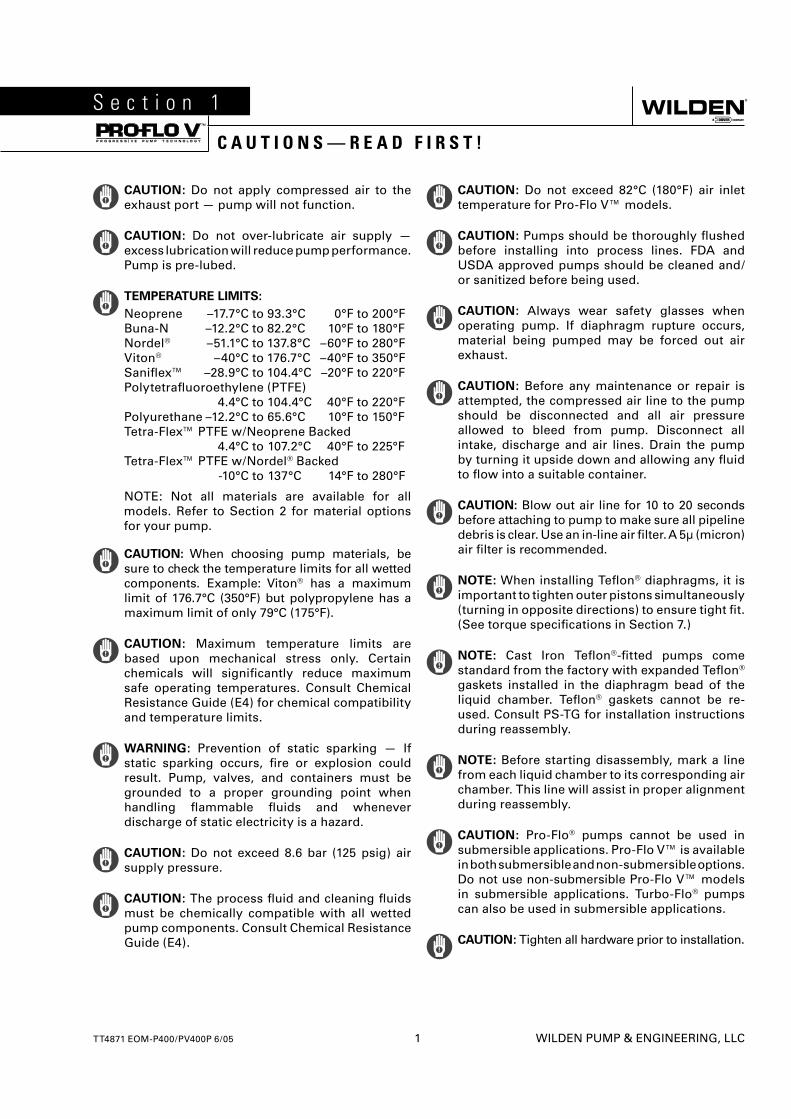
CAUTION: Do not apply compressed air to the exhaust port — pump will not function.
CAUTION: Do not over-lubricate air supply — excess lubrication will reduce pump performance. Pump is pre-lubed.
TEMPERATURE LIMITS:
Neoprene –17.7°C to 93.3°C 0°F to 200°F Buna-N –12.2°C to 82.2°C 10°F to 180°F Nordel® –51.1°C to 137.8°C –60°F to 280°F Viton® –40°C to 176.7°C –40°F to 350°F Sanifl ex™ –28.9°C to 104.4°C –20°F to 220°F Polytetrafl uoroethylene (PTFE) 4.4°C to 104.4°C 40°F to 220°F Polyurethane –12.2°C to 65.6°C 10°F to 150°F Tetra-Flex™ PTFE w/Neoprene Backed 4.4°C to 107.2°C 40°F to 225°F Tetra-Flex™ PTFE w/Nordel® Backed -10°C to 137°C 14°F to 280°F
NOTE: Not all materials are available for all models. Refer to Section 2 for material options for your pump.
CAUTION: When choosing pump materials, be sure to check the temperature limits for all wetted components. Example: Viton® has a maximum limit of 176.7°C (350°F) but polypropylene has a maximum limit of only 79°C (175°F).
CAUTION: Maximum temperature limits are based upon mechanical stress only. Certain chemicals will signifi cantly reduce maximum safe operating temperatures. Consult Chemical Resistance Guide (E4) for chemical compatibility and temperature limits.
WARNING: Prevention of static sparking — If static sparking occurs, fi re or explosion could result. Pump, valves, and containers must be grounded to a proper grounding point when handling fl ammable fl uids and whenever discharge of static electricity is a hazard.
CAUTION: Do not exceed 8.6 bar (125 psig) air supply pressure.
CAUTION: The process fl uid and cleaning fl uids must be chemically compatible with all wetted pump components. Consult Chemical Resistance Guide (E4).
CAUTION: Do not exceed 82°C (180°F) air inlet temperature for Pro-Flo V™ models.
CAUTION: Pumps should be thoroughly fl ushed before installing into process lines. FDA and USDA approved pumps should be cleaned and/or sanitized before being used.
CAUTION: Always wear safety glasses when operating pump. If diaphragm rupture occurs, material being pumped may be forced out air exhaust.
CAUTION: Before any maintenance or repair is attempted, the compressed air line to the pump should be disconnected and all air pressure allowed to bleed from pump. Disconnect all intake, discharge and air lines. Drain the pump by turning it upside down and allowing any fl uid to fl ow into a suitable container.
CAUTION: Blow out air line for 10 to 20 seconds before attaching to pump to make sure all pipeline debris is clear. Use an in-line air fi lter. A 5µ (micron) air fi lter is recommended.
NOTE: When installing Tefl on® diaphragms, it is important to tighten outer pistons simultaneously (turning in opposite directions) to ensure tight fi t. (See torque specifi cations in Section 7.)
NOTE: Cast Iron Tefl on®-fi tted pumps come standard from the factory with expanded Tefl on®
gaskets installed in the diaphragm bead of the liquid chamber. Tefl on® gaskets cannot be re-used. Consult PS-TG for installation instructions during reassembly.
NOTE: Before starting disassembly, mark a line from each liquid chamber to its corresponding air chamber. This line will assist in proper alignment during reassembly.
CAUTION: Pro-Flo® pumps cannot be used in submersible applications. Pro-Flo V™ is available in both submersible and non-submersible options. Do not use non-submersible Pro-Flo V™ models in submersible applications. Turbo-Flo® pumps can also be used in submersible applications.
CAUTION: Tighten all hardware prior to installation.
S e c t i o n 1
C A U T I O N S — R E A D F I R S T !
S e c t i o n 2
W I L D E N P U M P D E S I G N A T I O N S Y S T E M
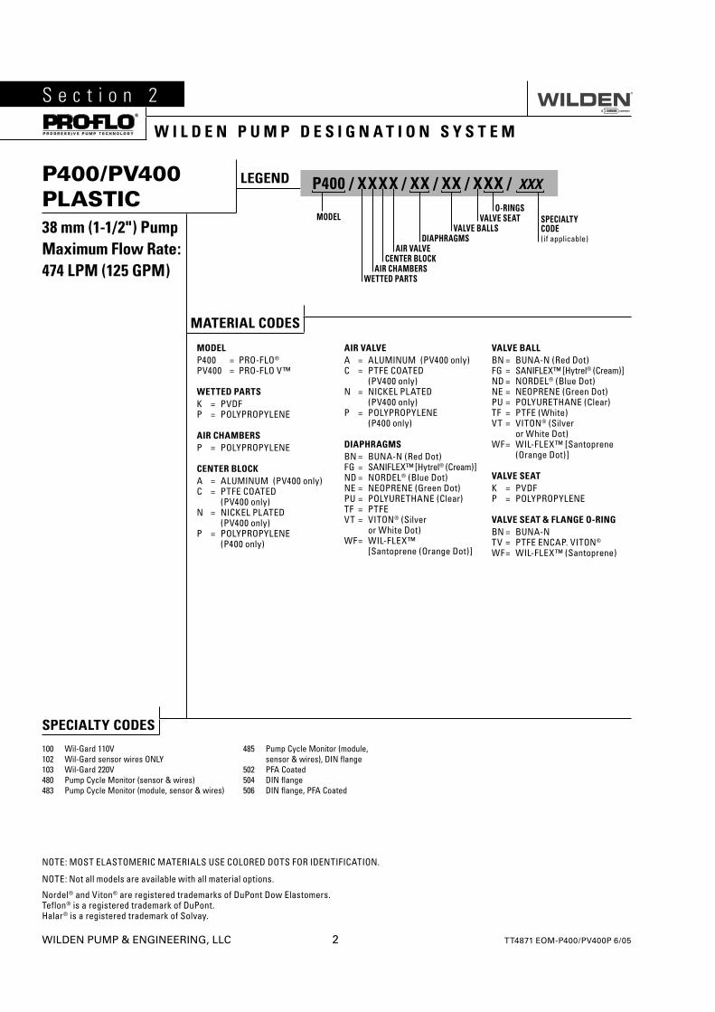
P400/PV400 PLASTIC38 mm (1-1/2") PumpMaximum Flow Rate:474 LPM (125 GPM)
LEGEND P400 / XXXX / XX / XX / XXX / XXX
O-RINGSMODEL VALVE SEAT
VALVE BALLSDIAPHRAGMS
AIR VALVECENTER BLOCK
AIR CHAMBERSWETTED PARTS
SPECIALTYCODE(if applicable)
MATERIAL CODES
MODELP400 = PRO-FLO®
PV400 = PRO-FLO V™
WETTED PARTSK = PVDFP = POLYPROPYLENE
AIR CHAMBERSP = POLYPROPYLENE
CENTER BLOCKA = ALUMINUM (PV400 only)C = PTFE COATED
(PV400 only)N = NICKEL PLATED
(PV400 only)P = POLYPROPYLENE
(P400 only)
AIR VALVEA = ALUMINUM (PV400 only)C = PTFE COATED
(PV400 only)N = NICKEL PLATED
(PV400 only)P = POLYPROPYLENE
(P400 only)
DIAPHRAGMSBN = BUNA-N (Red Dot)FG = SANIFLEX™ [Hytrel® (Cream)]ND = NORDEL® (Blue Dot)NE = NEOPRENE (Green Dot)PU = POLYURETHANE (Clear)TF = PTFEVT = VITON® (Silver
or White Dot)WF = WIL-FLEX™
[Santoprene (Orange Dot)]
VALVE BALLBN = BUNA-N (Red Dot)FG = SANIFLEX™ [Hytrel® (Cream)]ND = NORDEL® (Blue Dot)NE = NEOPRENE (Green Dot)PU = POLYURETHANE (Clear)TF = PTFE (White)VT = VITON® (Silver
or White Dot)WF = WIL-FLEX™ [Santoprene
(Orange Dot)]
VALVE SEATK = PVDFP = POLYPROPYLENE
VALVE SEAT & FLANGE O-RINGBN = BUNA-NTV = PTFE ENCAP. VITON®
WF = WIL-FLEX™ (Santoprene)
NOTE: MOST ELASTOMERIC MATERIALS USE COLORED DOTS FOR IDENTIFICATION.
NOTE: Not all models are available with all material options.
Nordel® and Viton® are registered trademarks of DuPont Dow Elastomers.Teflon® is a registered trademark of DuPont.Halar® is a registered trademark of Solvay.
SPECIALTY CODES
100 Wil-Gard 110V102 Wil-Gard sensor wires ONLY103 Wil-Gard 220V480 Pump Cycle Monitor (sensor & wires)483 Pump Cycle Monitor (module, sensor & wires)
485 Pump Cycle Monitor (module, sensor & wires), DIN flange
502 PFA Coated504 DIN flange506 DIN flange, PFA Coated
WILDEN PUMP & ENGINEERING, LLC 2 TT4871 EOM-P400/PV400P 6/05
TT4871 EOM-P400/PV400P 6/05 3 WILDEN PUMP & ENGINEERING, LLC
S e c t i o n 3
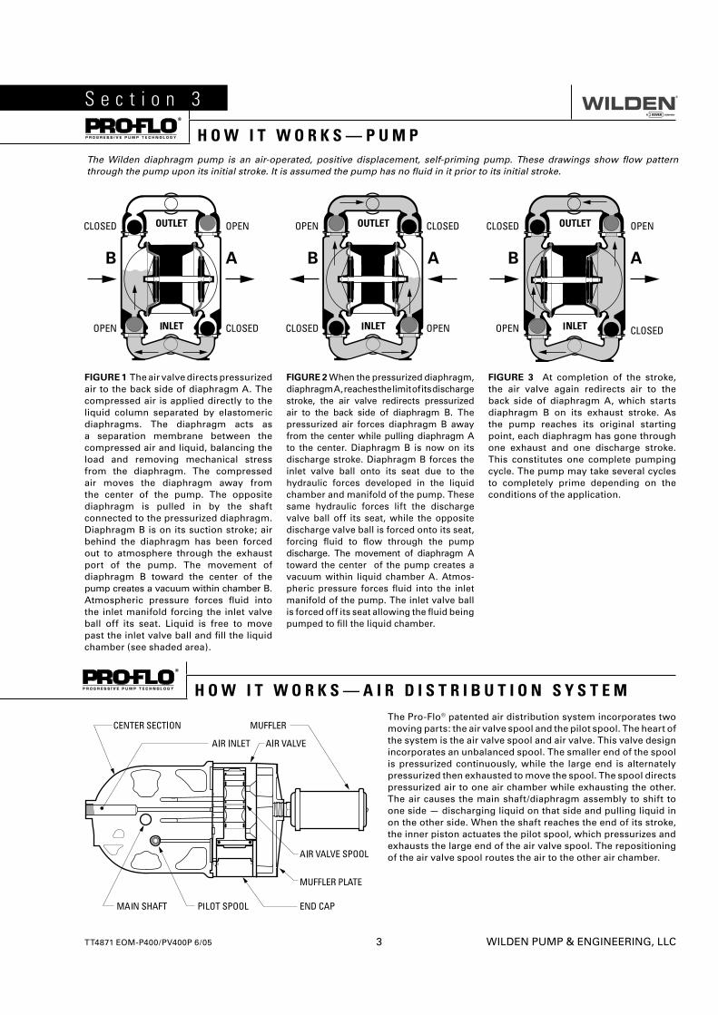
H O W I T W O R K S — P U M PThe Wilden diaphragm pump is an air-operated, positive displacement, self-priming pump. These drawings show fl ow pattern through the pump upon its initial stroke. It is assumed the pump has no fl uid in it prior to its initial stroke.
FIGURE 1 The air valve directs pressurized air to the back side of diaphragm A. The compressed air is applied directly to the liquid column separated by elastomeric diaphragms. The diaphragm acts as a separation membrane between the compressed air and liquid, balancing the load and removing mechanical stress from the diaphragm. The compressed air moves the diaphragm away from the center of the pump. The opposite diaphragm is pulled in by the shaft connected to the pressurized diaphragm. Diaphragm B is on its suction stroke; air behind the diaphragm has been forced out to atmosphere through the exhaust port of the pump. The movement of diaphragm B toward the center of the pump creates a vacuum within chamber B. Atmospheric pressure forces fl uid into the inlet manifold forcing the inlet valve ball off its seat. Liquid is free to move past the inlet valve ball and fi ll the liquid chamber (see shaded area).
FIGURE 2 When the pressurized diaphragm, diaphragm A, reaches the limit of its discharge stroke, the air valve redirects pressurized air to the back side of diaphragm B. The pressurized air forces diaphragm B away from the center while pulling diaphragm A to the center. Diaphragm B is now on its discharge stroke. Diaphragm B forces the inlet valve ball onto its seat due to the hydraulic forces developed in the liquid chamber and manifold of the pump. These same hydraulic forces lift the discharge valve ball off its seat, while the opposite discharge valve ball is forced onto its seat, forcing fl uid to fl ow through the pump discharge. The movement of diaphragm A toward the center of the pump creates a vacuum within liquid chamber A. Atmos-pheric pressure forces fl uid into the inlet manifold of the pump. The inlet valve ball is forced off its seat allowing the fl uid being pumped to fi ll the liquid chamber.
FIGURE 3 At completion of the stroke, the air valve again redirects air to the back side of diaphragm A, which starts diaphragm B on its exhaust stroke. As the pump reaches its original starting point, each diaphragm has gone through one exhaust and one discharge stroke. This constitutes one complete pumping cycle. The pump may take several cycles to completely prime depending on the conditions of the application.
The Pro-Flo® patented air distribution system incorporates two moving parts: the air valve spool and the pilot spool. The heart of the system is the air valve spool and air valve. This valve design incorporates an unbalanced spool. The smaller end of the spool is pressurized continuously, while the large end is alternately pressurized then exhausted to move the spool. The spool directs pressurized air to one air chamber while exhausting the other. The air causes the main shaft/diaphragm assembly to shift to one side — discharging liquid on that side and pulling liquid in on the other side. When the shaft reaches the end of its stroke, the inner piston actuates the pilot spool, which pressurizes and exhausts the large end of the air valve spool. The repositioning of the air valve spool routes the air to the other air chamber.
H O W I T W O R K S — A I R D I S T R I B U T I O N S Y S T E M
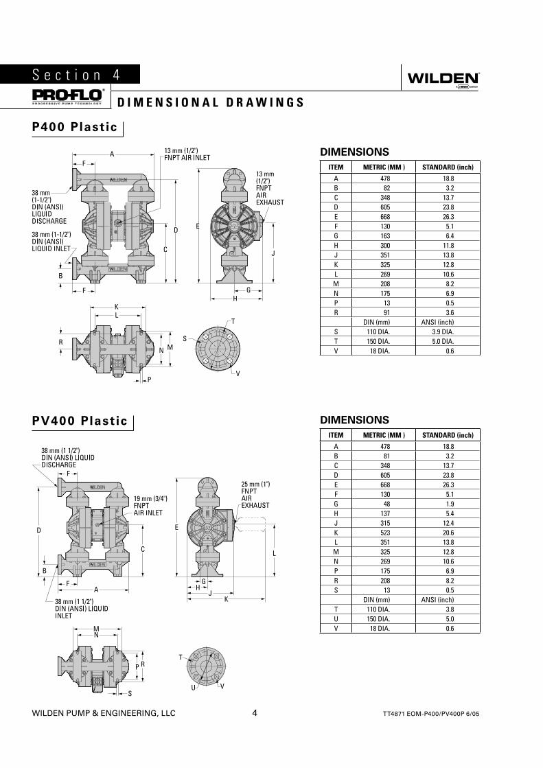
P400 Plastic
PV400 Plastic
DIMENSIONS
ITEM METRIC (MM ) STANDARD (inch)
A 478 18.8B 82 3.2C 348 13.7D 605 23.8E 668 26.3F 130 5.1G 163 6.4H 300 11.8J 351 13.8K 325 12.8L 269 10.6M 208 8.2N 175 6.9P 13 0.5R 91 3.6
DIN (mm) ANSI (inch)S 110 DIA. 3.9 DIA.T 150 DIA. 5.0 DIA.V 18 DIA. 0.6
DIMENSIONS
ITEM METRIC (MM ) STANDARD (inch)
A 478 18.8B 81 3.2C 348 13.7D 605 23.8E 668 26.3F 130 5.1G 48 1.9H 137 5.4J 315 12.4K 523 20.6L 351 13.8M 325 12.8N 269 10.6P 175 6.9R 208 8.2S 13 0.5
DIN (mm) ANSI (inch)T 110 DIA. 3.8U 150 DIA. 5.0V 18 DIA. 0.6
WILDEN PUMP & ENGINEERING, LLC 4 TT4871 EOM-P400/PV400P 6/05
S e c t i o n 4
D I M E N S I O N A L D R A W I N G S
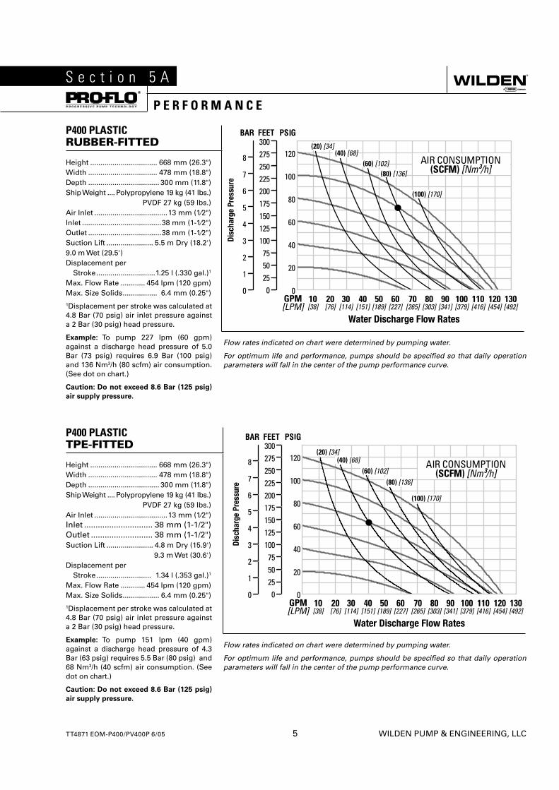
P400 PLASTICRUBBER-FITTED
Flow rates indicated on chart were determined by pumping water.
For optimum life and performance, pumps should be specifi ed so that daily operation parameters will fall in the center of the pump performance curve.
Height ................................. 668 mm (26.3")Width .................................. 478 mm (18.8") Depth ................................... 300 mm (11.8") Ship Weight .... Polypropylene 19 kg (41 lbs.) PVDF 27 kg (59 lbs.)Air Inlet ....................................13 mm (1⁄2")Inlet .......................................38 mm (1-1⁄2")Outlet ....................................38 mm (1-1⁄2")Suction Lift ....................... 5.5 m Dry (18.2')9.0 m Wet (29.5')Displacement per Stroke .............................1.25 l (.330 gal.)1
Max. Flow Rate ............ 454 lpm (120 gpm)Max. Size Solids ................. 6.4 mm (0.25")1Displacement per stroke was calculated at 4.8 Bar (70 psig) air inlet pressure against a 2 Bar (30 psig) head pressure.
Example: To pump 227 lpm (60 gpm) against a discharge head pressure of 5.0 Bar (73 psig) requires 6.9 Bar (100 psig) and 136 Nm3/h (80 scfm) air consumption. (See dot on chart.)
Caution: Do not exceed 8.6 Bar (125 psig)
air supply pressure.
P400 PLASTIC TPE-FITTED
Flow rates indicated on chart were determined by pumping water.
For optimum life and performance, pumps should be specifi ed so that daily operation parameters will fall in the center of the pump performance curve.
Height ................................. 668 mm (26.3")Width .................................. 478 mm (18.8") Depth ................................... 300 mm (11.8") Ship Weight .... Polypropylene 19 kg (41 lbs.) PVDF 27 kg (59 lbs.)Air Inlet ....................................13 mm (1⁄2")Inlet .............................. 38 mm (1-1/2")Outlet ........................... 38 mm (1-1/2")Suction Lift ....................... 4.8 m Dry (15.9') 9.3 m Wet (30.6') Displacement per Stroke ........................... 1.34 l (.353 gal.)1
Max. Flow Rate ............ 454 lpm (120 gpm)Max. Size Solids .................. 6.4 mm (0.25")1Displacement per stroke was calculated at 4.8 Bar (70 psig) air inlet pressure against a 2 Bar (30 psig) head pressure.
Example: To pump 151 lpm (40 gpm) against a discharge head pressure of 4.3 Bar (63 psig) requires 5.5 Bar (80 psig) and 68 Nm3/h (40 scfm) air consumption. (See dot on chart.)
Caution: Do not exceed 8.6 Bar (125 psig)
air supply pressure.
TT4871 EOM-P400/PV400P 6/05 5 WILDEN PUMP & ENGINEERING, LLC
S e c t i o n 5 A
P E R F O R M A N C E
WILDEN PUMP & ENGINEERING, LLC 6 TT4871 EOM-P400/PV400P 6/05
P E R F O R M A N C E
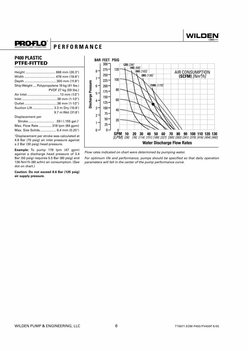
P400 PLASTICPTFE-FITTED
Flow rates indicated on chart were determined by pumping water.
For optimum life and performance, pumps should be specifi ed so that daily operation parameters will fall in the center of the pump performance curve.
Height ................................. 668 mm (26.3")Width .................................. 478 mm (18.8") Depth ................................... 300 mm (11.8") Ship Weight .... Polypropylene 19 kg (41 lbs.) PVDF 27 kg (59 lbs.)Air Inlet ....................................13 mm (1⁄2")Inlet .......................................38 mm (1-1⁄2")Outlet ....................................38 mm (1-1⁄2")Suction Lift ....................... 3.3 m Dry (10.8') 9.7 m Wet (31.8') Displacement per Stroke ............................. .59 l (.155 gal.)1
Max. Flow Rate .............. 318 lpm (84 gpm)Max. Size Solids .................. 6.4 mm (0.25")1Displacement per stroke was calculated at 4.8 Bar (70 psig) air inlet pressure against a 2 Bar (30 psig) head pressure.
Example: To pump 178 lpm (47 gpm) against a discharge head pressure of 3.4 Bar (50 psig) requires 5.5 Bar (80 psig) and 136 Nm3/h (80 scfm) air consumption. (See dot on chart.)
Caution: Do not exceed 8.6 Bar (125 psig)
air supply pressure.
TT4871 EOM-P400/PV400P 6/05 7 WILDEN PUMP & ENGINEERING, LLC
P E R F O R M A N C E
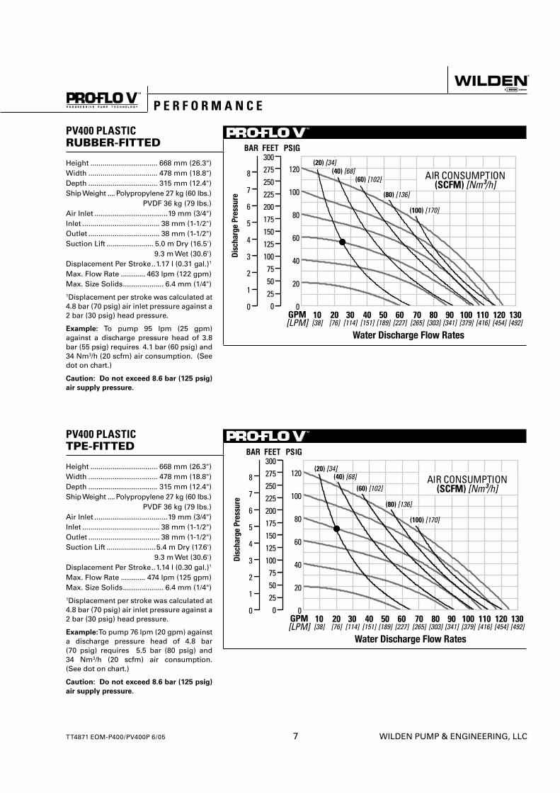
PV400 PLASTICRUBBER-FITTED
Height ................................. 668 mm (26.3")Width .................................. 478 mm (18.8")Depth .................................. 315 mm (12.4")Ship Weight ....Polypropylene 27 kg (60 lbs.) PVDF 36 kg (79 lbs.)Air Inlet ....................................19 mm (3/4")Inlet ...................................... 38 mm (1-1/2") Outlet ................................... 38 mm (1-1/2")Suction Lift ....................... 5.0 m Dry (16.5') 9.3 m Wet (30.6')Displacement Per Stroke ..1.17 l (0.31 gal.)1
Max. Flow Rate ............ 463 lpm (122 gpm)Max. Size Solids .................... 6.4 mm (1/4")1Displacement per stroke was calculated at 4.8 bar (70 psig) air inlet pressure against a 2 bar (30 psig) head pressure.
Example: To pump 95 lpm (25 gpm) against a discharge pressure head of 3.8 bar (55 psig) requires 4.1 bar (60 psig) and 34 Nm3/h (20 scfm) air consumption. (See dot on chart.)
Caution: Do not exceed 8.6 bar (125 psig)
air supply pressure.
PV400 PLASTICTPE-FITTED
Height ................................. 668 mm (26.3")Width .................................. 478 mm (18.8")Depth .................................. 315 mm (12.4")Ship Weight ....Polypropylene 27 kg (60 lbs.) PVDF 36 kg (79 lbs.)Air Inlet ....................................19 mm (3/4")Inlet ...................................... 38 mm (1-1/2") Outlet ................................... 38 mm (1-1/2")Suction Lift ........................5.4 m Dry (17.6') 9.3 m Wet (30.6')Displacement Per Stroke ..1.14 l (0.30 gal.)1
Max. Flow Rate ............ 474 lpm (125 gpm)Max. Size Solids .................... 6.4 mm (1/4")1Displacement per stroke was calculated at 4.8 bar (70 psig) air inlet pressure against a 2 bar (30 psig) head pressure.
Example: To pump 76 lpm (20 gpm) against a discharge pressure head of 4.8 bar (70 psig) requires 5.5 bar (80 psig) and 34 Nm3/h (20 scfm) air consumption. (See dot on chart.)
Caution: Do not exceed 8.6 bar (125 psig)
air supply pressure.
WILDEN PUMP & ENGINEERING, LLC 8 TT4871 EOM-P400/PV400P 6/05
P E R F O R M A N C E
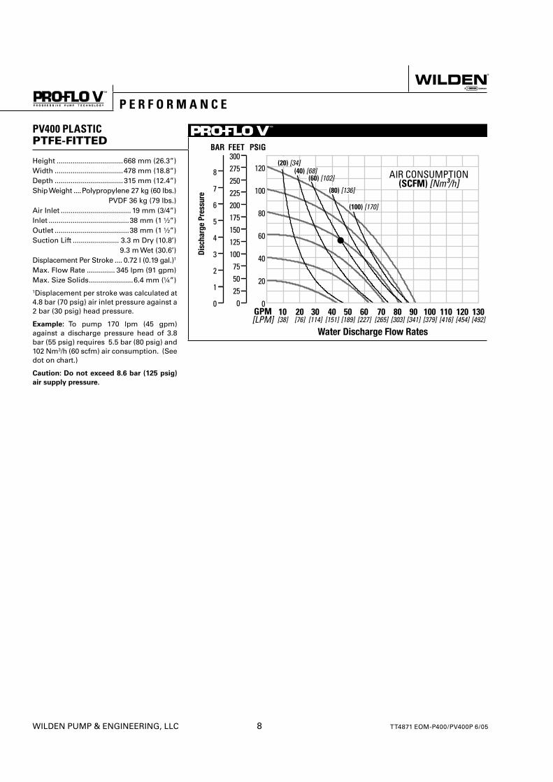
PV400 PLASTICPTFE-FITTED
Height .................................668 mm (26.3”)Width ..................................478 mm (18.8”)Depth ..................................315 mm (12.4”)Ship Weight ....Polypropylene 27 kg (60 lbs.) PVDF 36 kg (79 lbs.)Air Inlet ................................... 19 mm (3/4”)Inlet ........................................38 mm (1 ½”) Outlet .....................................38 mm (1 ½”)Suction Lift ....................... 3.3 m Dry (10.8’) 9.3 m Wet (30.6’)Displacement Per Stroke .... 0.72 l (0.19 gal.)1
Max. Flow Rate .............. 345 lpm (91 gpm)Max. Size Solids ......................6.4 mm (¼”)1Displacement per stroke was calculated at 4.8 bar (70 psig) air inlet pressure against a 2 bar (30 psig) head pressure.
Example: To pump 170 lpm (45 gpm) against a discharge pressure head of 3.8 bar (55 psig) requires 5.5 bar (80 psig) and 102 Nm3/h (60 scfm) air consumption. (See dot on chart.)
Caution: Do not exceed 8.6 bar (125 psig)
air supply pressure.
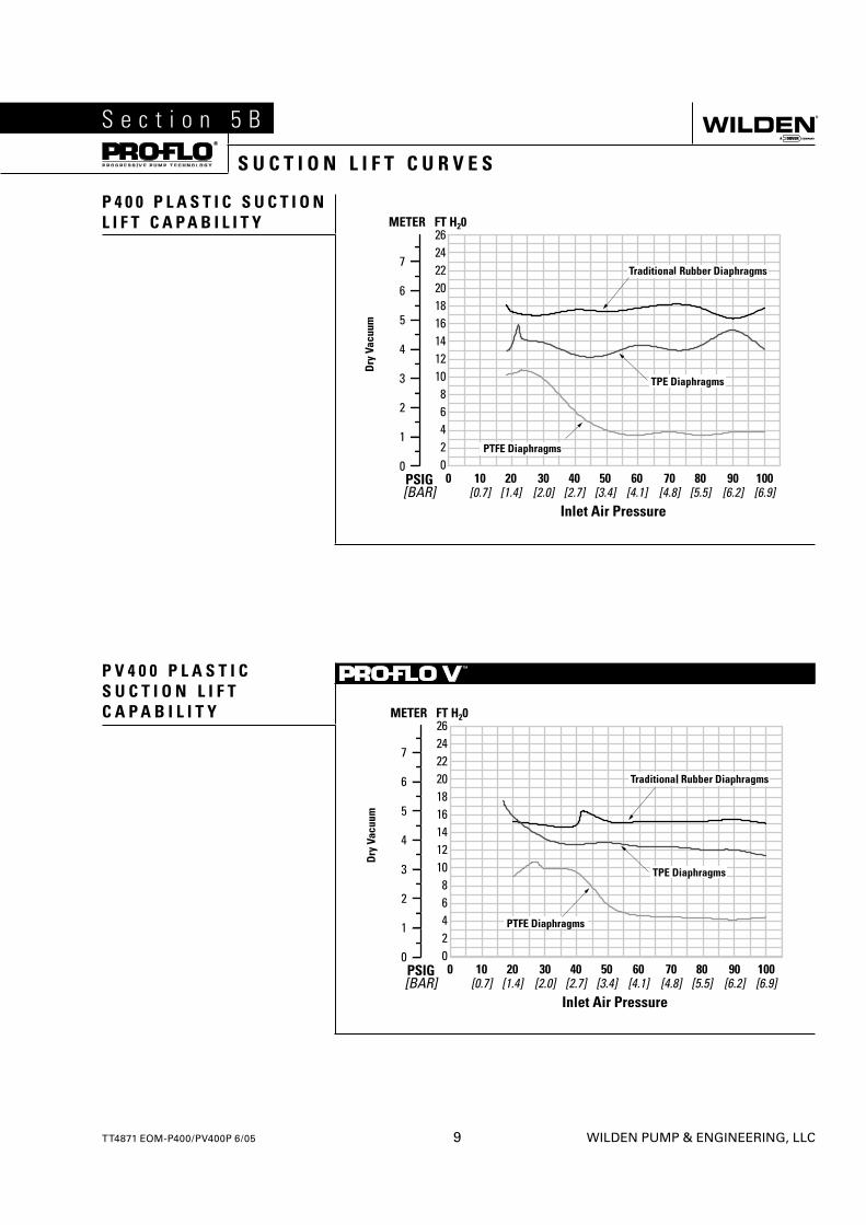
P 4 0 0 P L A S T I C S U C T I O N L I F T C A P A B I L I T Y
P V 4 0 0 P L A S T I C S U C T I O N L I F T C A P A B I L I T Y
TT4871 EOM-P400/PV400P 6/05 9 WILDEN PUMP & ENGINEERING, LLC
S e c t i o n 5 B
S U C T I O N L I F T C U R V E S
WILDEN PUMP & ENGINEERING, LLC 10 TT4871 EOM-P400/PV400P 6/05
S e c t i o n 6
S U G G E S T E D I N S T A L L A T I O NWilden pumps are designed to meet the performance requirements of even the most demanding pumping applications. They have been designed and manufactured to the highest standards and are available in a variety of liquid path materials to meet your chemical resistance needs. Refer to the performance section of this manual for an in-depth analysis of the performance characteristics of your pump. Wilden offers the widest variety of elastomer options in the industry to satisfy temperature, chemical compatibility, abrasion resistance and fl ex concerns.
The suction pipe size should be at least the equivalent or larger than the diameter size of the suction inlet on your Wilden pump. The suction hose must be non-collapsible, reinforced type as these pumps are capable of pulling a high vacuum. Discharge piping should also be the equivalent or larger than the diameter of the pump discharge which will help reduce friction losses. It is critical that all fi ttings and connections are airtight or a reduction or loss of pump suction capability will result.
INSTALLATION: Months of careful planning, study, and selection efforts can result in unsatisfactory pump performance if installation details are left to chance.
Premature failure and long term dissatisfaction can be avoided if reasonable care is exercised throughout the installation process.
LOCATION: Noise, safety, and other logistical factors usually dictate where equipment will be situated on the production fl oor. Multiple installations with confl icting requirements can result in congestion of utility areas, leaving few choices for additional pumps.
Within the framework of these and other existing conditions, every pump should be located in such a way that six key factors are balanced against each other to maximum advantage.
ACCESS: First of all, the location should be accessible. If it’s easy to reach the pump, maintenance personnel will have an easier time carrying out routine inspections and adjustments. Should major repairs become necessary, ease of access can play a key role in speeding the repair process and reducing total downtime.
AIR SUPPLY: Every pump location should have an air line large enough to supply the volume of air necessary to achieve the desired pumping rate. Use air pressure up to a maximum of 8.6 bar (125 psig) depending on pumping requirements.
For best results, the pumps should use a 5µ (micron) air fi lter, needle valve and regulator. The use of an air fi lter before the pump will ensure that the majority of any pipeline contaminants will be eliminated.
SOLENOID OPERATION: When operation is controlled by a solenoid valve in the air line, three-way valves should be used. This valve allows trapped air between the valve and the pump to bleed off which improves pump performance. Pumping volume can be estimated by counting the number of strokes per minute and then multiplying the fi gure by the displacement per stroke.
MUFFLER: Sound levels are reduced below OSHA specifi cations using the standard Wilden muffl er. Other
muffl ers can be used to further reduce sound levels, but they usually reduce pump performance.
ELEVATION: Selecting a site that is well within the pump’s dynamic lift capability will assure that loss-of-prime issues will be eliminated. In addition, pump effi ciency can be adversely affected if proper attention is not given to site location.
PIPING: Final determination of the pump site should not be made until the piping challenges of each possible location have been evaluated. The impact of current and future installations should be considered ahead of time to make sure that inadvertent restrictions are not created for any remaining sites.
The best choice possible will be a site involving the shortest and straightest hook-up of suction and discharge piping. Unnecessary elbows, bends, and fi ttings should be avoided. Pipe sizes should be selected to keep friction losses within practical limits. All piping should be supported independently of the pump. In addition, the piping should be aligned to avoid placing stress on the pump fi ttings.
Flexible hose can be installed to aid in absorbing the forces created by the natural reciprocating action of the pump. If the pump is to be bolted down to a solid location, a mounting pad placed between the pump and the foundation will assist in minimizing pump vibration. Flexible connections between the pump and rigid piping will also assist in minimizing pump vibration. If quick-closing valves are installed at any point in the discharge system, or if pulsation within a system becomes a problem, a surge suppressor (SD Equalizer®)should be installed to protect the pump, piping and gauges from surges and water hammer.
If the pump is to be used in a self-priming application, make sure that all connections are airtight and that the suction lift is within the model’s ability. Note: Materials of construction and elastomer material have an effect on suction lift parameters. Please refer to the performance section for specifi cs.
When pumps are installed in applications involving fl ooded suction or suction head pressures, a gate valve should be installed in the suction line to permit closing of the line for pump service.
Pumps in service with a positive suction head are most effi cient when inlet pressure is limited to 0.5–0.7 bar (7–10 psig). Premature diaphragm failure may occur if positive suction is 0.7 bar (10 psig) and higher.
SUBMERSIBLE APPLICATIONS: Pro-Flo V™ pumps can be used for submersible applications, when using the Pro-Flo V™ submersible option. Turbo-Flo™ pumps can also be used for submersible applications.
NOTE: Pro-Flo® and Accu-Flo™ pumps are not submersible.
ALL WILDEN PUMPS ARE CAPABLE OF PASSING SOLIDS. A STRAINER SHOULD BE USED ON THE PUMP INTAKE TO ENSURE THAT THE PUMP'S RATED SOLIDS CAPACITY IS NOT EXCEEDED.
CAUTION: DO NOT EXCEED 8.6 BAR (125 PSIG) AIR SUPPLY PRESSURE.
TT4871 EOM-P400/PV400P 6/05 11 WILDEN PUMP & ENGINEERING, LLC
S U G G E S T E D I N S T A L L A T I O N
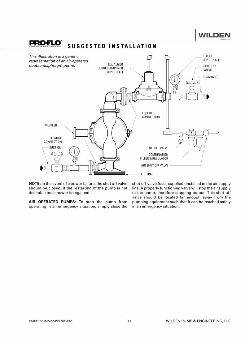
NOTE: In the event of a power failure, the shut off valve should be closed, if the restarting of the pump is not desirable once power is regained.
AIR OPERATED PUMPS: To stop the pump from operating in an emergency situation, simply close the
shut off valve (user supplied) installed in the air supply line. A properly functioning valve will stop the air supply to the pump, therefore stopping output. This shut off valve should be located far enough away from the pumping equipment such that it can be reached safely in an emergency situation.
This illustration is a generic representation of an air-operated double-diaphragm pump.
WILDEN PUMP & ENGINEERING, LLC 12 TT4871 EOM-P400/PV400P 6/05
S U G G E S T E D O P E R A T I O N & M A I N T E N A N C E
OPERATION: The P400 and PV400 are pre-lubricated, and do not require in-line lubrication. Additional lubrication will not damage the pump, however if the pump is heavily lubricated by an external source, the pump’s internal lubrication may be washed away. If the pump is then moved to a non-lubricated location, it may need to be disassembled and re-lubricated as described in the ASSEMBLY/DISASSEMBLY INSTRUCTIONS.
Pump discharge rate can be controlled by limiting the volume and/or pressure of the air supply to the pump. An air regulator is used to regulate air pressure. A needle valve is used to regulate volume. Pump discharge rate can also be controlled by throttling the pump discharge by partially closing a valve in the discharge line of the pump. This action increases friction loss which reduces fl ow rate. (See Section 5.) This is useful when the need exists to control the pump from a remote location. When the pump discharge pressure equals or exceeds the air supply pressure, the pump will stop; no bypass or pressure relief valve is needed, and pump damage will not occur. The pump has reached a “deadhead” situation and can
be restarted by reducing the fl uid discharge pressure or increasing the air inlet pressure. The Wilden P400 and PV400 pumps run solely on compressed air and do not generate heat, therefore your process fl uid temperature will not be affected.
MAINTENANCE AND INSPECTIONS: Since each application is unique, maintenance schedules may be different for every pump. Frequency of use, line pressure, viscosity and abrasiveness of process fl uid all affect the parts life of a Wilden pump. Periodic inspections have been found to offer the best means for preventing unscheduled pump downtime. Personnel familiar with the pump’s construction and service should be informed of any abnormalities that are detected during operation.
RECORDS: When service is required, a record should be made of all necessary repairs and replacements. Over a period of time, such records can become a valuable tool for predicting and preventing future maintenance problems and unscheduled downtime. In addition, accurate records make it possible to identify pumps that are poorly suited to their applications.
T R O U B L E S H O O T I N G
Pump will not run or runs slowly.
1. Ensure that the air inlet pressure is at least 0.4 bar (5 psig) above startup pressure and that the differential pressure (the difference between air inlet and liquid discharge pressures) is not less than 0.7 bar (10 psig).
2. Check air inlet fi lter for debris (see recommended installation).
3. Check for extreme air leakage (blow by) which would indicate worn seals/bores in the air valve, pilot spool, main shaft.
4. Disassemble pump and check for obstructions in the air passageways or objects which would obstruct the movement of internal parts.
5. Check for sticking ball check valves. If material being pumped is not compatible with pump elastomers, swelling may occur. Replace ball check valves and seals with proper elastomers. Also, as the check valve balls wear out, they become smaller and can become stuck in the seats. In this case, replace balls and seats.
6. Check for broken inner piston which will cause the air valve spool to be unable to shift.
7. Remove plug from pilot spool exhaust.
Pump runs but little or no product fl ows.
1. Check for pump cavitation; slow pump speed down to allow thick material to fl ow into liquid chambers.
2. Verify that vacuum required to lift liquid is not greater than the vapor pressure of the material being pumped (cavitation).
3. Check for sticking ball check valves. If material being pumped is not compatible with pump elastomers, swelling may occur. Replace ball check valves and seats with proper elastomers. Also, as the check valve balls wear out, they become smaller and can become stuck in the seats. In this case, replace balls and seats.
Pump air valve freezes.
1. Check for excessive moisture in compressed air. Either install a dryer or hot air generator for compressed air. Alternatively, a coalescing fi lter may be used to remove the water from the compressed air in some applications.
Air bubbles in pump discharge.
1. Check for ruptured diaphragm.2. Check tightness of outer pistons (refer to Section 7).3. Check tightness of fasteners and integrity of
o-rings and seals, especially at intake manifold.4. Ensure pipe connections are airtight.
Product comes out air exhaust.
1. Check for diaphragm rupture.2. Check tightness of outer pistons to shaft.
Step 1
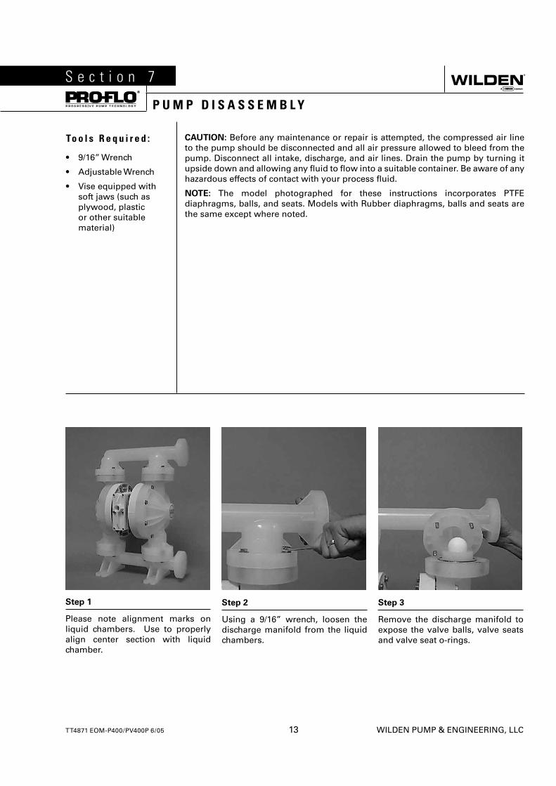
Please note alignment marks on liquid chambers. Use to properly align center section with liquid chamber.
Step 2
Using a 9/16” wrench, loosen the discharge manifold from the liquid chambers.
Step 3
Remove the discharge manifold to expose the valve balls, valve seats and valve seat o-rings.
S e c t i o n 7
P U M P D I S A S S E M B L Y
To o l s R e q u i r e d :
• 9/16” Wrench
• Adjustable Wrench
• Vise equipped with soft jaws (such as plywood, plastic or other suitable material)
CAUTION: Before any maintenance or repair is attempted, the compressed air line to the pump should be disconnected and all air pressure allowed to bleed from the pump. Disconnect all intake, discharge, and air lines. Drain the pump by turning it upside down and allowing any fl uid to fl ow into a suitable container. Be aware of any hazardous effects of contact with your process fl uid.
NOTE: The model photographed for these instructions incorporates PTFE diaphragms, balls, and seats. Models with Rubber diaphragms, balls and seats are the same except where noted.
TT4871 EOM-P400/PV400P 6/05 13 WILDEN PUMP & ENGINEERING, LLC
Step 4
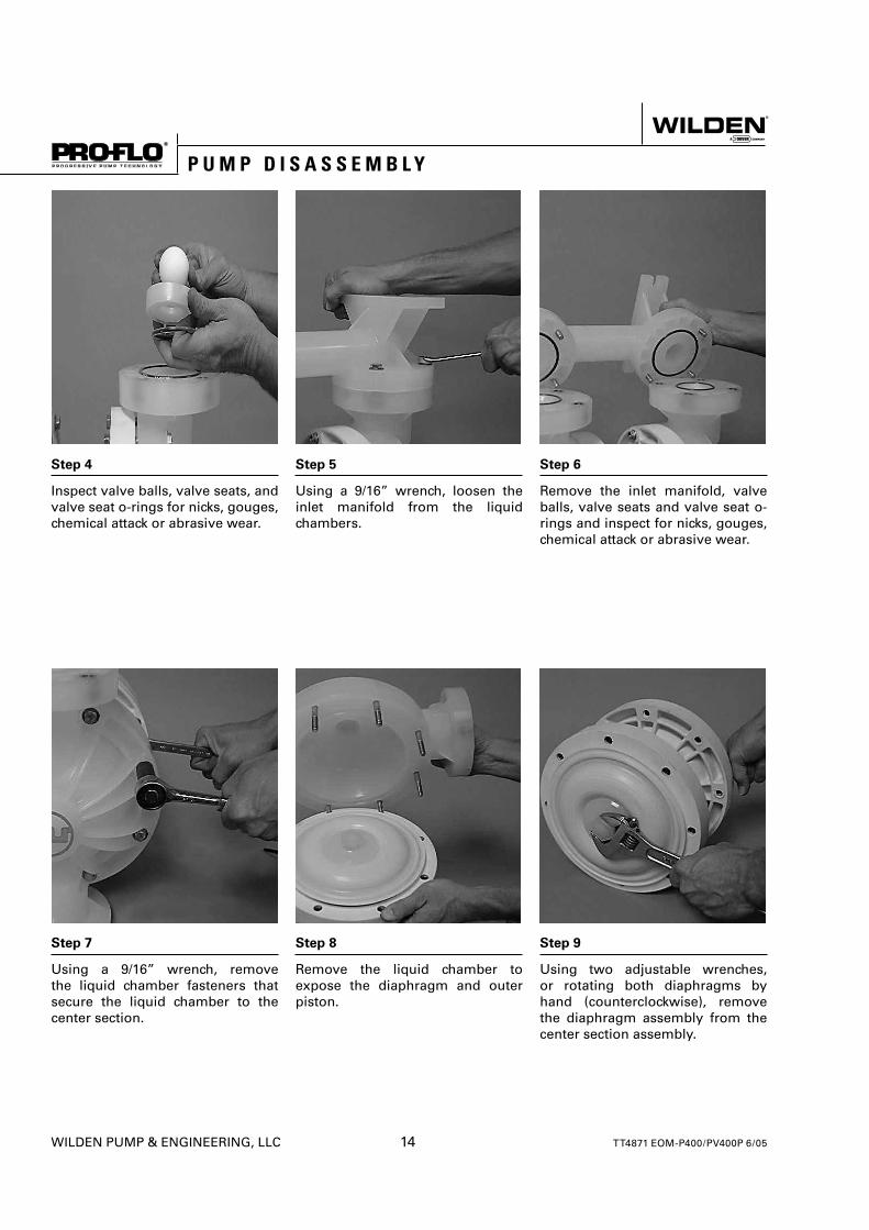
Inspect valve balls, valve seats, and valve seat o-rings for nicks, gouges, chemical attack or abrasive wear.
Step 5
Using a 9/16” wrench, loosen the inlet manifold from the liquid chambers.
Step 6
Remove the inlet manifold, valve balls, valve seats and valve seat o-rings and inspect for nicks, gouges, chemical attack or abrasive wear.
Step 7
Using a 9/16” wrench, remove the liquid chamber fasteners that secure the liquid chamber to the center section.
Step 8
Remove the liquid chamber to expose the diaphragm and outer piston.
Step 9
Using two adjustable wrenches, or rotating both diaphragms by hand (counterclockwise), remove the diaphragm assembly from the center section assembly.
P U M P D I S A S S E M B L Y
WILDEN PUMP & ENGINEERING, LLC 14 TT4871 EOM-P400/PV400P 6/05
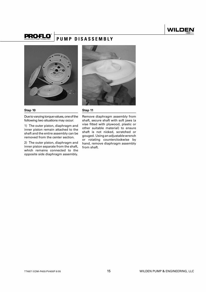
Step 10
Due to varying torque values, one of the following two situations may occur:
1) The outer piston, diaphragm and inner piston remain attached to the shaft and the entire assembly can be removed from the center section.
2) The outer piston, diaphragm and inner piston separate from the shaft, which remains connected to the opposite side diaphragm assembly.
Step 11
Remove diaphragm assembly from shaft, secure shaft with soft jaws (a vise fi tted with plywood, plastic or other suitable material) to ensure shaft is not nicked, scratched or gouged. Using an adjustable wrench or rotating counterclockwise by hand, remove diaphragm assembly from shaft.
P U M P D I S A S S E M B L Y
TT4871 EOM-P400/PV400P 6/05 15 WILDEN PUMP & ENGINEERING, LLC
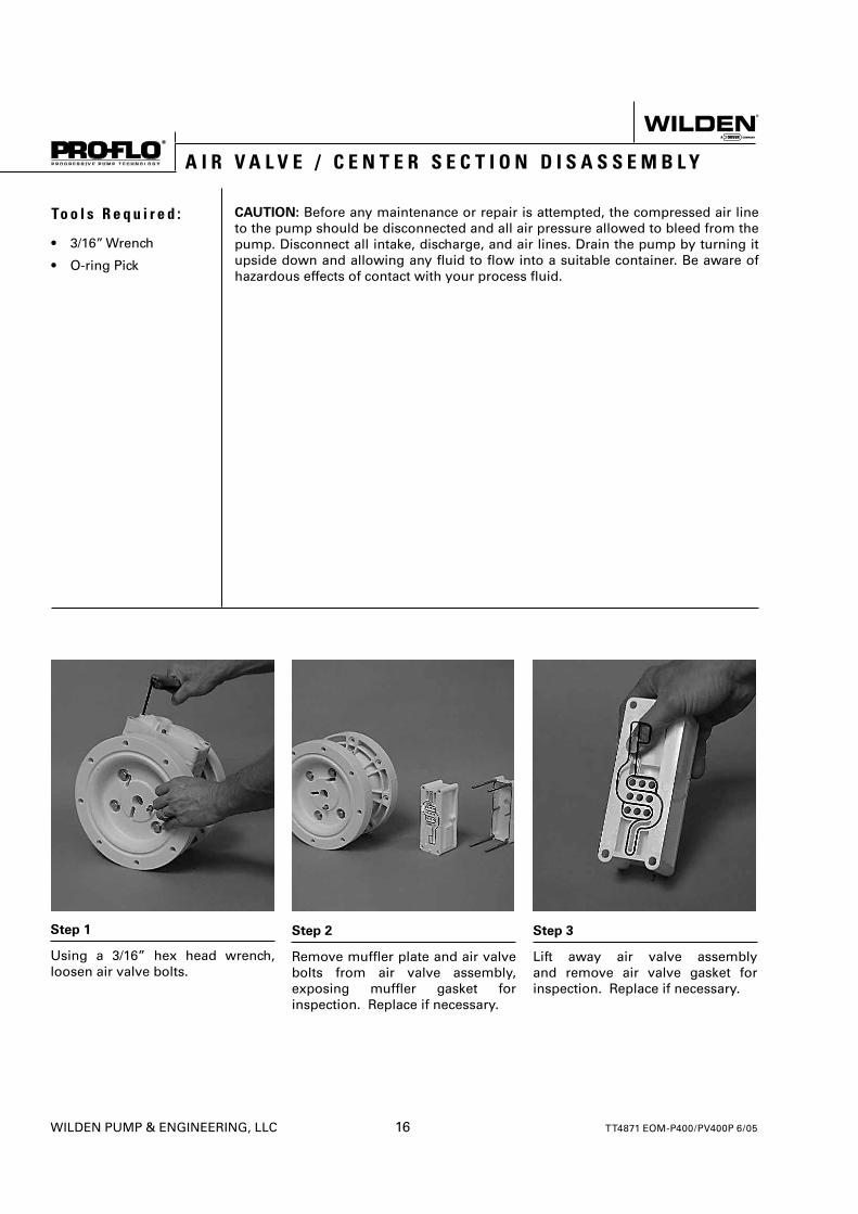
Step 1
Using a 3/16” hex head wrench, loosen air valve bolts.
Step 2
Remove muffl er plate and air valve bolts from air valve assembly, exposing muffl er gasket for inspection. Replace if necessary.
Step 3
Lift away air valve assembly and remove air valve gasket for inspection. Replace if necessary.
To o l s R e q u i r e d :
• 3/16” Wrench
• O-ring Pick
CAUTION: Before any maintenance or repair is attempted, the compressed air line to the pump should be disconnected and all air pressure allowed to bleed from the pump. Disconnect all intake, discharge, and air lines. Drain the pump by turning it upside down and allowing any fl uid to fl ow into a suitable container. Be aware of hazardous effects of contact with your process fl uid.
A I R V A L V E / C E N T E R S E C T I O N D I S A S S E M B L Y
WILDEN PUMP & ENGINEERING, LLC 16 TT4871 EOM-P400/PV400P 6/05
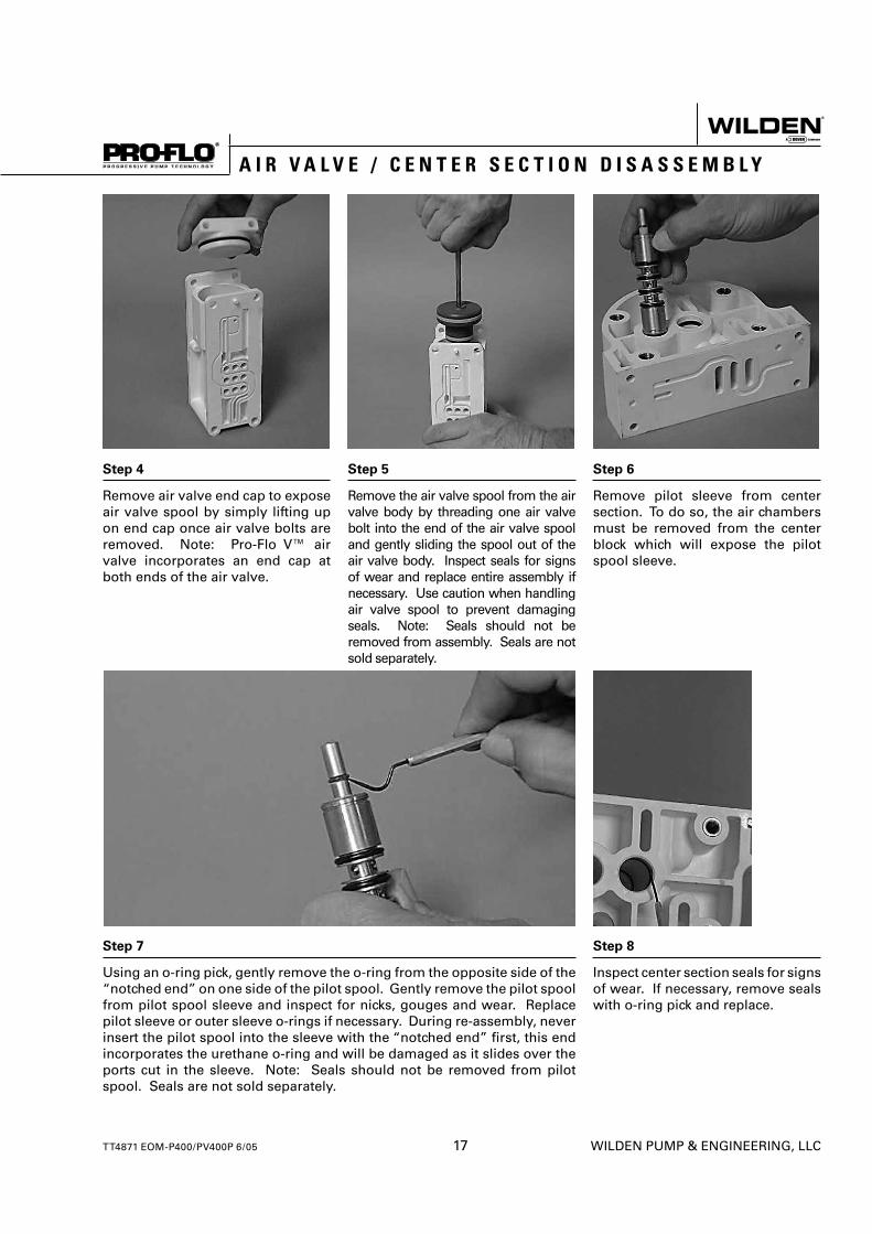
Step 4
Remove air valve end cap to expose air valve spool by simply lifting up on end cap once air valve bolts are removed. Note: Pro-Flo V™ air valve incorporates an end cap at both ends of the air valve.
Step 5
Remove the air valve spool from the air valve body by threading one air valve bolt into the end of the air valve spool and gently sliding the spool out of the air valve body. Inspect seals for signs of wear and replace entire assembly if necessary. Use caution when handling air valve spool to prevent damaging seals. Note: Seals should not be removed from assembly. Seals are not sold separately.
Step 6
Remove pilot sleeve from center section. To do so, the air chambers must be removed from the center block which will expose the pilot spool sleeve.
Step 7
Using an o-ring pick, gently remove the o-ring from the opposite side of the “notched end” on one side of the pilot spool. Gently remove the pilot spool from pilot spool sleeve and inspect for nicks, gouges and wear. Replace pilot sleeve or outer sleeve o-rings if necessary. During re-assembly, never insert the pilot spool into the sleeve with the “notched end” fi rst, this end incorporates the urethane o-ring and will be damaged as it slides over the ports cut in the sleeve. Note: Seals should not be removed from pilot spool. Seals are not sold separately.
Step 8
Inspect center section seals for signs of wear. If necessary, remove seals with o-ring pick and replace.
A I R V A L V E / C E N T E R S E C T I O N D I S A S S E M B L Y
TT4871 EOM-P400/PV400P 6/05 17 WILDEN PUMP & ENGINEERING, LLC
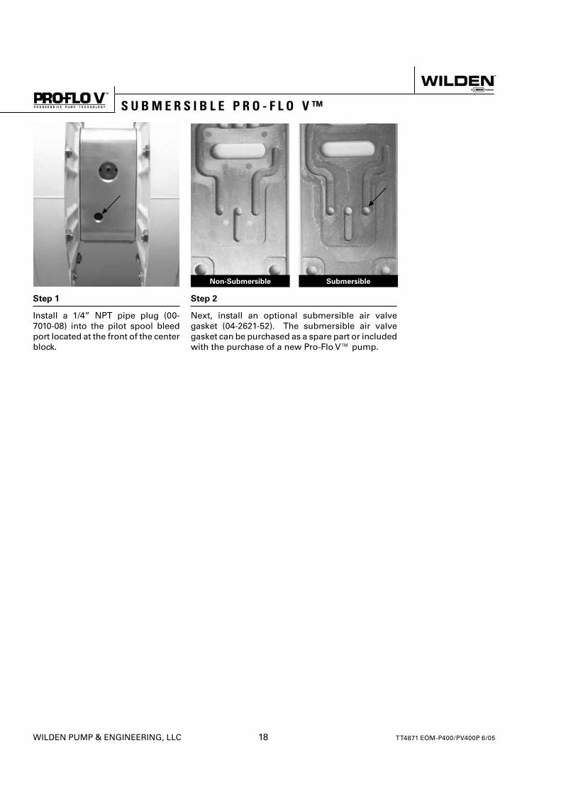
Step 1
Install a 1/4” NPT pipe plug (00-7010-08) into the pilot spool bleed port located at the front of the center block.
Step 2
Next, install an optional submersible air valve gasket (04-2621-52). The submersible air valve gasket can be purchased as a spare part or included with the purchase of a new Pro-Flo V™ pump.
Non-Submersible Submersible
S U B M E R S I B L E P R O - F L O V ™
WILDEN PUMP & ENGINEERING, LLC 18 TT4871 EOM-P400/PV400P 6/05
ASSEMBLY:
Upon performing applicable maintenance to the air distribution system, the pump can now be reassembled. Please refer to the disassembly instructions for photos and parts placement. To reassemble the pump, follow the disassembly instructions in reverse order. The air distribution system needs to be assembled fi rst, then the diaphragms and fi nally the wetted path. Please fi nd the applicable torque specifi cations on this page. The following tips will assist in the assembly process.
• Lubricate air valve bore, center section shaft and pilot spool bore with NLGI grade 2 white EP bearing grease or equivalent.
• Clean the inside of the center section shaft bore to ensure no damage is done to new seals.
• A small amount NLGI grade 2 white EP bearing grease can be applied to the muffl er and air valve gaskets to locate gaskets during assembly.
• Make sure that the exhaust port on the muffl er plate is centered between the two exhaust ports on the center section.
• Stainless bolts should be lubed to reduce the possibility of seizing during tightening.
PRO-FLO® MAXIMUM TORQUE SPECIFICATIONS
Description of Part Torque
Pro-Flo® Air Valve Bolts 5.1 N•m (45 in-lbs)
Air Chamber to Center Block 47.5 N•m (35 ft-lbs)
Outer Piston 51.5 N•m (38 ft-lbs)
Manifolds to Liquid Chamber 9.6 N•m (85 in-lbs)
Liquid Chamber to Air Chamber 9.6 N•m (85 in-lbs)
PRO-FLO V™ MAXIMUM TORQUE SPECIFICATIONS
Description of Part Torque
Pro-Flo® Air Valve Bolts 13.6 N•m (120 in-lbs)
Air Chamber to Center Block 27.1 N•m (20 ft-lbs)
Outer Piston 51.5 N•m (38 ft-lbs)
Manifolds to Liquid Chamber 9.6 N•m (85 in-lbs)
Liquid Chamber to Air Chamber 9.6 N•m (85 in-lbs)
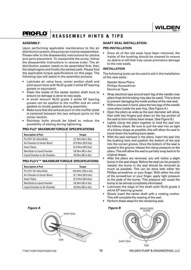
SHAFT SEAL INSTALLATION:
PRE-INSTALLATION
• Once all of the old seals have been removed, the inside of the bushing should be cleaned to ensure no debris is left that may cause premature damage to the new seals.
INSTALLATION
The following tools can be used to aid in the installation of the new seals:
Needle Nose Pliers Phillips Screwdriver Electrical Tape
• Wrap electrical tape around each leg of the needle nose pliers (heat shrink tubing may also be used). This is done to prevent damaging the inside surface of the new seal.
• With a new seal in hand, place the two legs of the needle nose pliers inside the seal ring. (See Figure A.)
• Open the pliers as wide as the seal diameter will allow, then with two fi ngers pull down on the top portion of the seal to form kidney bean shape. (See Figure B.)
• Lightly clamp the pliers together to hold the seal into the kidney shape. Be sure to pull the seal into as tight of a kidney shape as possible, this will allow the seal to travel down the bushing bore easier.
• With the seal clamped in the pliers, insert the seal into the bushing bore and position the bottom of the seal into the correct groove. Once the bottom of the seal is seated in the groove, release the clamp pressure on the pliers. This will allow the seal to partially snap back to its original shape.
• After the pliers are removed, you will notice a slight bump in the seal shape. Before the seal can be properly resized, the bump in the seal should be removed as much as possible. This can be done with either the Phillips screwdriver or your fi nger. With either the side of the screwdriver or your fi nger, apply light pressure to the peak of the bump. This pressure will cause the bump to be almost completely eliminated.
• Lubricate the edge of the shaft with NLGI grade 2 white EP bearing grease.
• Slowly insert the center shaft with a rotating motion. This will complete the resizing of the seal.
• Perform these steps for the remaining seal.
Figure A
SHAFT SEAL
TAPE
Figure B
SHAFT SEAL
TAPE
NEEDLE NOSE PLIERS
R E A S S E M B L Y H I N T S & T I P S
TT4871 EOM-P400/PV400P 6/05 19 WILDEN PUMP & ENGINEERING, LLC
WILDEN PUMP & ENGINEERING, LLC 20 TT4871 EOM-P400/PV400P 6/05
S e c t i o n 8
E X P L O D E D V I E W A N D P A R T S L I S T I N G
32
33
35 18
22
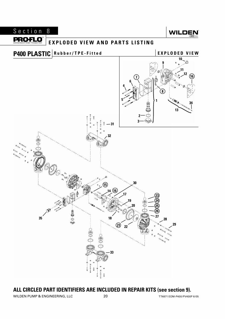
P400 PLASTIC R u b b e r / T P E - F i t t e d E X P L O D E D V I E W
2829
24252627
20
30
17
19
14
31
8
46
1
13
2
34
3
5
11
910
ALL CIRCLED PART IDENTIFIERS ARE INCLUDED IN REPAIR KITS (see section 9).
127 16
15
1623
21
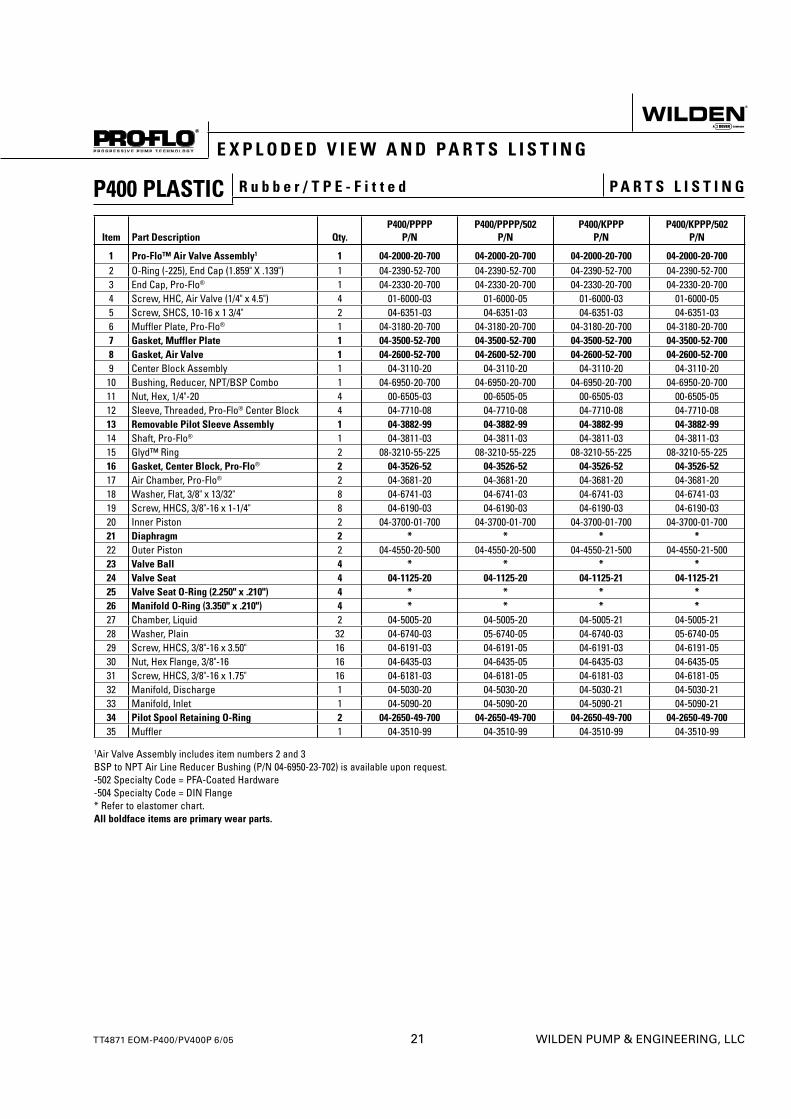
P400 PLASTIC R u b b e r / T P E - F i t t e d P A R T S L I S T I N G
E X P L O D E D V I E W A N D P A R T S L I S T I N G
TT4871 EOM-P400/PV400P 6/05 21 WILDEN PUMP & ENGINEERING, LLC
Item Part Description Qty.P400/PPPP
P/NP400/PPPP/502
P/NP400/KPPP
P/NP400/KPPP/502
P/N
1 Pro-Flo™ Air Valve Assembly1 1 04-2000-20-700 04-2000-20-700 04-2000-20-700 04-2000-20-7002 O-Ring (-225), End Cap (1.859" X .139") 1 04-2390-52-700 04-2390-52-700 04-2390-52-700 04-2390-52-7003 End Cap, Pro-Flo® 1 04-2330-20-700 04-2330-20-700 04-2330-20-700 04-2330-20-7004 Screw, HHC, Air Valve (1/4" x 4.5") 4 01-6000-03 01-6000-05 01-6000-03 01-6000-055 Screw, SHCS, 10-16 x 1 3/4" 2 04-6351-03 04-6351-03 04-6351-03 04-6351-036 Muffler Plate, Pro-Flo® 1 04-3180-20-700 04-3180-20-700 04-3180-20-700 04-3180-20-7007 Gasket, Muffler Plate 1 04-3500-52-700 04-3500-52-700 04-3500-52-700 04-3500-52-7008 Gasket, Air Valve 1 04-2600-52-700 04-2600-52-700 04-2600-52-700 04-2600-52-7009 Center Block Assembly 1 04-3110-20 04-3110-20 04-3110-20 04-3110-2010 Bushing, Reducer, NPT/BSP Combo 1 04-6950-20-700 04-6950-20-700 04-6950-20-700 04-6950-20-70011 Nut, Hex, 1/4"-20 4 00-6505-03 00-6505-05 00-6505-03 00-6505-0512 Sleeve, Threaded, Pro-Flo® Center Block 4 04-7710-08 04-7710-08 04-7710-08 04-7710-0813 Removable Pilot Sleeve Assembly 1 04-3882-99 04-3882-99 04-3882-99 04-3882-9914 Shaft, Pro-Flo® 1 04-3811-03 04-3811-03 04-3811-03 04-3811-0315 Glyd™ Ring 2 08-3210-55-225 08-3210-55-225 08-3210-55-225 08-3210-55-22516 Gasket, Center Block, Pro-Flo® 2 04-3526-52 04-3526-52 04-3526-52 04-3526-5217 Air Chamber, Pro-Flo® 2 04-3681-20 04-3681-20 04-3681-20 04-3681-2018 Washer, Flat, 3/8" x 13/32" 8 04-6741-03 04-6741-03 04-6741-03 04-6741-0319 Screw, HHCS, 3/8"-16 x 1-1/4" 8 04-6190-03 04-6190-03 04-6190-03 04-6190-0320 Inner Piston 2 04-3700-01-700 04-3700-01-700 04-3700-01-700 04-3700-01-70021 Diaphragm 2 * * * *22 Outer Piston 2 04-4550-20-500 04-4550-20-500 04-4550-21-500 04-4550-21-50023 Valve Ball 4 * * * *24 Valve Seat 4 04-1125-20 04-1125-20 04-1125-21 04-1125-2125 Valve Seat O-Ring (2.250" x .210") 4 * * * *26 Manifold O-Ring (3.350" x .210") 4 * * * *27 Chamber, Liquid 2 04-5005-20 04-5005-20 04-5005-21 04-5005-2128 Washer, Plain 32 04-6740-03 05-6740-05 04-6740-03 05-6740-0529 Screw, HHCS, 3/8"-16 x 3.50" 16 04-6191-03 04-6191-05 04-6191-03 04-6191-0530 Nut, Hex Flange, 3/8"-16 16 04-6435-03 04-6435-05 04-6435-03 04-6435-0531 Screw, HHCS, 3/8"-16 x 1.75" 16 04-6181-03 04-6181-05 04-6181-03 04-6181-0532 Manifold, Discharge 1 04-5030-20 04-5030-20 04-5030-21 04-5030-2133 Manifold, Inlet 1 04-5090-20 04-5090-20 04-5090-21 04-5090-2134 Pilot Spool Retaining O-Ring 2 04-2650-49-700 04-2650-49-700 04-2650-49-700 04-2650-49-70035 Muffler 1 04-3510-99 04-3510-99 04-3510-99 04-3510-99
1Air Valve Assembly includes item numbers 2 and 3BSP to NPT Air Line Reducer Bushing (P/N 04-6950-23-702) is available upon request.-502 Specialty Code = PFA-Coated Hardware-504 Specialty Code = DIN Flange* Refer to elastomer chart.All boldface items are primary wear parts.
WILDEN PUMP & ENGINEERING, LLC 22 TT4871 EOM-P400/PV400P 6/05
E X P L O D E D V I E W A N D P A R T S L I S T I N G
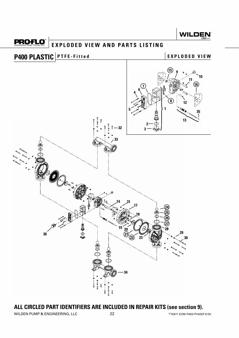
P400 PLASTIC P T F E - F i t t e d E X P L O D E D V I E W
11
8
46
7
1
132
35
3
5
12
16
15 910
ALL CIRCLED PART IDENTIFIERS ARE INCLUDED IN REPAIR KITS (see section 9).
33
2930
2425262728
34
32
3622 23
212019
3117
18
14
TT4871 EOM-P400/PV400P 6/05 23 WILDEN PUMP & ENGINEERING, LLC
E X P L O D E D V I E W A N D P A R T S L I S T I N G
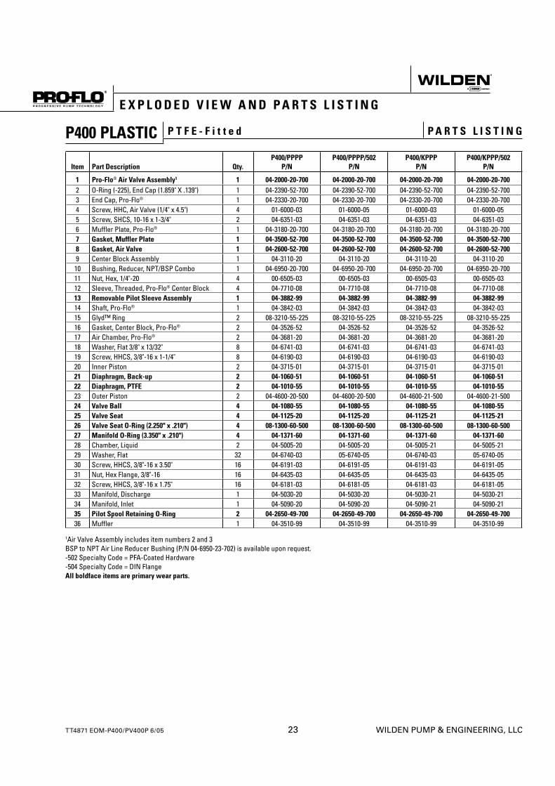
P400 PLASTIC P T F E - F i t t e d P A R T S L I S T I N G
Item Part Description Qty.P400/PPPP
P/NP400/PPPP/502
P/NP400/KPPP
P/NP400/KPPP/502
P/N
1 Pro-Flo® Air Valve Assembly1 1 04-2000-20-700 04-2000-20-700 04-2000-20-700 04-2000-20-7002 O-Ring (-225), End Cap (1.859" X .139") 1 04-2390-52-700 04-2390-52-700 04-2390-52-700 04-2390-52-7003 End Cap, Pro-Flo® 1 04-2330-20-700 04-2330-20-700 04-2330-20-700 04-2330-20-7004 Screw, HHC, Air Valve (1/4" x 4.5") 4 01-6000-03 01-6000-05 01-6000-03 01-6000-055 Screw, SHCS, 10-16 x 1-3/4" 2 04-6351-03 04-6351-03 04-6351-03 04-6351-036 Muffler Plate, Pro-Flo® 1 04-3180-20-700 04-3180-20-700 04-3180-20-700 04-3180-20-7007 Gasket, Muffler Plate 1 04-3500-52-700 04-3500-52-700 04-3500-52-700 04-3500-52-7008 Gasket, Air Valve 1 04-2600-52-700 04-2600-52-700 04-2600-52-700 04-2600-52-7009 Center Block Assembly 1 04-3110-20 04-3110-20 04-3110-20 04-3110-2010 Bushing, Reducer, NPT/BSP Combo 1 04-6950-20-700 04-6950-20-700 04-6950-20-700 04-6950-20-70011 Nut, Hex, 1/4"-20 4 00-6505-03 00-6505-03 00-6505-03 00-6505-0312 Sleeve, Threaded, Pro-Flo® Center Block 4 04-7710-08 04-7710-08 04-7710-08 04-7710-0813 Removable Pilot Sleeve Assembly 1 04-3882-99 04-3882-99 04-3882-99 04-3882-9914 Shaft, Pro-Flo® 1 04-3842-03 04-3842-03 04-3842-03 04-3842-0315 Glyd™ Ring 2 08-3210-55-225 08-3210-55-225 08-3210-55-225 08-3210-55-22516 Gasket, Center Block, Pro-Flo® 2 04-3526-52 04-3526-52 04-3526-52 04-3526-5217 Air Chamber, Pro-Flo® 2 04-3681-20 04-3681-20 04-3681-20 04-3681-2018 Washer, Flat 3/8" x 13/32" 8 04-6741-03 04-6741-03 04-6741-03 04-6741-0319 Screw, HHCS, 3/8"-16 x 1-1/4" 8 04-6190-03 04-6190-03 04-6190-03 04-6190-0320 Inner Piston 2 04-3715-01 04-3715-01 04-3715-01 04-3715-0121 Diaphragm, Back-up 2 04-1060-51 04-1060-51 04-1060-51 04-1060-5122 Diaphragm, PTFE 2 04-1010-55 04-1010-55 04-1010-55 04-1010-5523 Outer Piston 2 04-4600-20-500 04-4600-20-500 04-4600-21-500 04-4600-21-50024 Valve Ball 4 04-1080-55 04-1080-55 04-1080-55 04-1080-5525 Valve Seat 4 04-1125-20 04-1125-20 04-1125-21 04-1125-2126 Valve Seat O-Ring (2.250" x .210") 4 08-1300-60-500 08-1300-60-500 08-1300-60-500 08-1300-60-50027 Manifold O-Ring (3.350" x .210") 4 04-1371-60 04-1371-60 04-1371-60 04-1371-6028 Chamber, Liquid 2 04-5005-20 04-5005-20 04-5005-21 04-5005-2129 Washer, Flat 32 04-6740-03 05-6740-05 04-6740-03 05-6740-0530 Screw, HHCS, 3/8"-16 x 3.50" 16 04-6191-03 04-6191-05 04-6191-03 04-6191-0531 Nut, Hex Flange, 3/8"-16 16 04-6435-03 04-6435-05 04-6435-03 04-6435-0532 Screw, HHCS, 3/8"-16 x 1.75" 16 04-6181-03 04-6181-05 04-6181-03 04-6181-0533 Manifold, Discharge 1 04-5030-20 04-5030-20 04-5030-21 04-5030-2134 Manifold, Inlet 1 04-5090-20 04-5090-20 04-5090-21 04-5090-2135 Pilot Spool Retaining O-Ring 2 04-2650-49-700 04-2650-49-700 04-2650-49-700 04-2650-49-70036 Muffler 1 04-3510-99 04-3510-99 04-3510-99 04-3510-99
1Air Valve Assembly includes item numbers 2 and 3BSP to NPT Air Line Reducer Bushing (P/N 04-6950-23-702) is available upon request.-502 Specialty Code = PFA-Coated Hardware-504 Specialty Code = DIN FlangeAll boldface items are primary wear parts.
WILDEN PUMP & ENGINEERING, LLC 24 TT4871 EOM-P400/PV400P 6/05
E X P L O D E D V I E W A N D P A R T S L I S T I N G
ALL CIRCLED PART IDENTIFIERS ARE INCLUDED IN REPAIR KITS (see section 9).
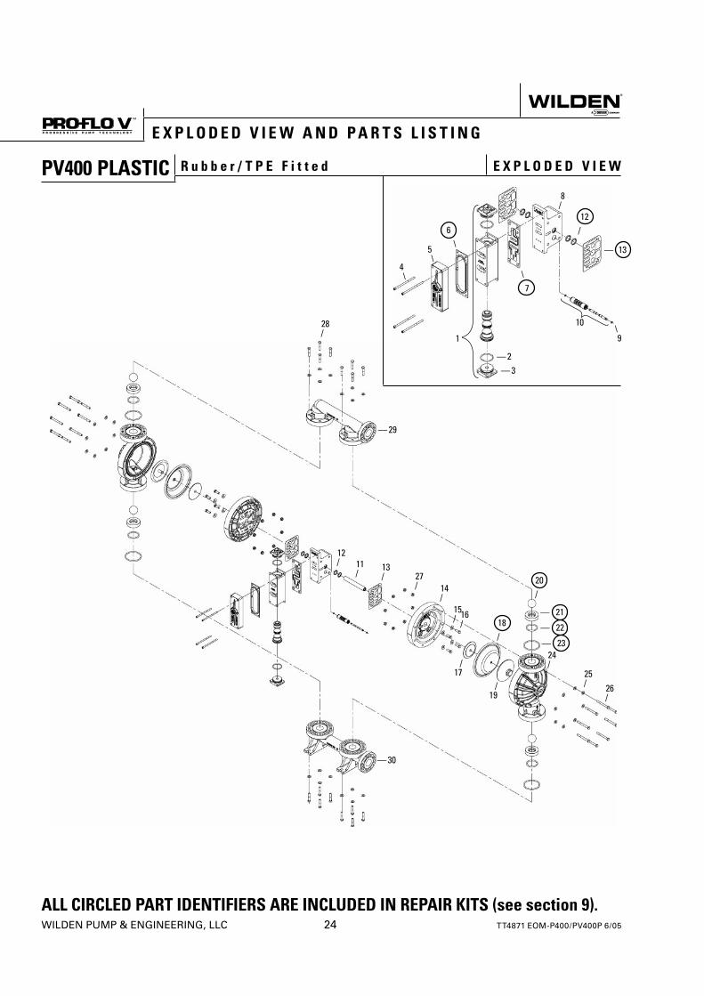
PV400 PLASTIC R u b b e r / T P E F i t t e d E X P L O D E D V I E W
28/
— 29
12/ 11
/13/ 27
/ 14/
15/ 16
/ 18/
20/
25/ 26
/
24/
/19
/17
— 30
4\
5\
6\
— 2— 3
\7
8/
12/
— 13
\91
10
— 21
— 22
— 23
TT4871 EOM-P400/PV400P 6/05 25 WILDEN PUMP & ENGINEERING, LLC
E X P L O D E D V I E W A N D P A R T S L I S T I N G
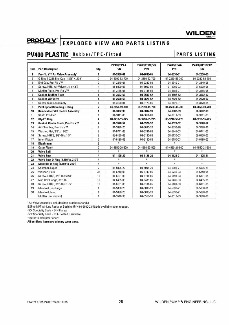
PV400 PLASTIC R u b b e r / T P E - F i t t e d P A R T S L I S T I N G
Item Part Description Qty.PV400/PPAA
P/NPV400/PPCC/502
P/NPV400/KPAA
P/NPV400/KPCC/502
P/N
1 Pro-Flo V™ Air Valve Assembly1 1 04-2030-01 04-2030-05 04-2030-01 04-2030-052 O-Ring (-225), End Cap (1.859" X .139") 2 04-2390-52-700 04-2390-52-700 04-2390-52-700 04-2390-52-7003 End Cap, Pro-Flo V™ 2 04-2340-01 04-2340-05 04-2340-01 04-2340-054 Screw, HHC, Air Valve (1/4" x 4.5") 4 01-6000-03 01-6000-05 01-6000-03 01-6000-055 Muffler Plate, Pro-Flo V™ 1 04-3185-01 04-3185-05 04-3185-01 04-3185-056 Gasket, Muffler Plate 1 04-3502-52 04-3502-52 04-3502-52 04-3502-527 Gasket, Air Valve 1 04-2620-52 04-2620-52 04-2620-52 04-2620-528 Center Block Assembly 1 04-3120-01 04-3120-05 04-3120-01 04-3120-059 Pilot Spool Retaining O-Ring 2 04-2650-49-700 04-2650-49-700 04-2650-49-700 04-2650-49-70010 Removable Pilot Sleeve Assembly 1 04-3882-99 04-3882-99 04-3882-99 04-3882-9911 Shaft, Pro-Flo® 1 04-3811-03 04-3811-03 04-3811-03 04-3811-0312 Glyd™ Ring 4 08-3210-55-225 08-3210-55-225 08-3210-55-225 08-3210-55-22513 Gasket, Center Block, Pro-Flo V™ 2 04-3528-52 04-3528-52 04-3528-52 04-3528-5214 Air Chamber, Pro-Flo V™ 2 04-3690-20 04-3690-20 04-3690-20 04-3690-2015 Washer, Flat, 3/8" x 13/32" 8 04-6741-03 04-6741-03 04-6741-03 04-6741-0316 Screw, HHCS, 3/8"-16 x 1 ¼" 8 08-6130-03 08-6130-03 08-6130-03 08-6130-0317 Inner Piston 2 04-6190-03 04-6190-03 04-6190-03 04-6190-0318 Diaphragm 2 * * * *19 Outer Piston 2 04-4550-20-500 04-4550-20-500 04-4550-21-500 04-4550-21-50020 Valve Ball 4 * * * *21 Valve Seat 4 04-1125-20 04-1125-20 04-1125-21 04-1125-2122 Valve Seat O-Ring (2.250" x .210") 4 * * * *23 Manifold O-Ring (3.350" x .210") 4 * * * *24 Chamber, Liquid 2 04-5005-20 04-5005-20 04-5005-21 04-5005-2125 Washer, Plain 32 04-6740-03 05-6740-05 04-6740-03 05-6740-0526 Screw, HHCS, 3/8"-16 x 3.50" 16 04-6191-03 04-6191-05 04-6191-03 04-6191-0527 Nut, Hex Flange, 3/8"-16 16 04-6435-03 04-6435-05 04-6435-03 04-6435-0528 Screw, HHCS, 3/8"-16 x 1.75" 16 04-6181-03 04-6181-05 04-6181-03 04-6181-0529 Manifold,Discharge 1 04-5030-20 04-5030-20 04-5030-21 04-5030-2130 Manifold, Inlet 1 04-5090-20 04-5090-20 04-5090-21 04-5090-21
Muffler (not shown) 1 04-3510-99 04-3510-99 04-3510-99 04-3510-99
1 Air Valve Assembly includes item numbers 2 and 3BSP to NPT Air Line Reducer Bushing (P/N 04-6950-23-702) is available upon request.-504 Specialty Code = DIN Flange -502 Specialty Code = PFA-Coated Hardware * Refer to elastomer chart.All boldface items are primary wear parts.
WILDEN PUMP & ENGINEERING, LLC 26 TT4871 EOM-P400/PV400P 6/05
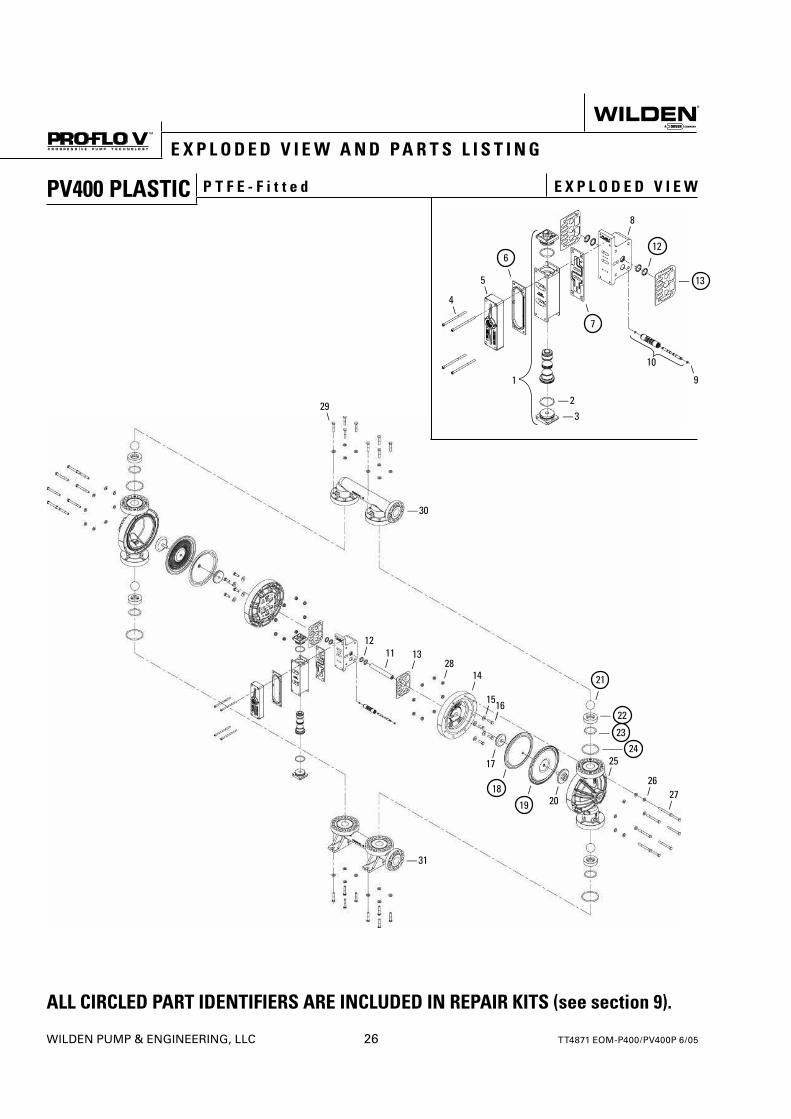
PV400 PLASTIC P T F E - F i t t e d E X P L O D E D V I E W
ALL CIRCLED PART IDENTIFIERS ARE INCLUDED IN REPAIR KITS (see section 9).
E X P L O D E D V I E W A N D P A R T S L I S T I N G
4\
5\
6\
— 2— 3
\7
8/
— 13
\91
10
29\
— 30
12/ 11
/13/ 28
/ 14/
15/ 16
/
21/
— 22
— 23
25/
26//
19
/17
— 31
/18 /
20
—— 24
27/
12/
TT4871 EOM-P400/PV400P 6/05 27 WILDEN PUMP & ENGINEERING, LLC
E X P L O D E D V I E W A N D P A R T S L I S T I N G
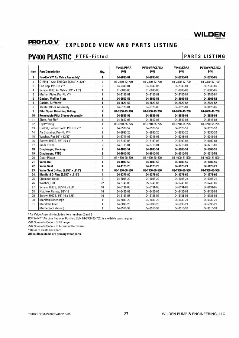
PV400 PLASTIC P T F E - F i t t e d P A R T S L I S T I N G
Item Part Description Qty.PV400/PPAA
P/NPV400/PPCC/502
P/NPV400/KPAA
P/NPV400/KPCC/502
P/N
1 Pro-Flo V™ Air Valve Assembly1 1 04-2030-01 04-2030-05 04-2030-01 04-2030-052 O-Ring (-225), End Cap (1.859" X .139") 2 04-2390-52-700 04-2390-52-700 04-2390-52-700 04-2390-52-7003 End Cap, Pro-Flo V™ 2 04-2340-01 04-2340-05 04-2340-01 04-2340-054 Screw, HHC, Air Valve (1/4" x 4.5") 4 01-6000-03 01-6000-05 01-6000-03 01-6000-055 Muffler Plate, Pro-Flo V™ 1 04-3185-01 04-3185-01 04-3185-01 04-3185-016 Gasket, Muffler Plate 1 04-3502-52 04-3502-52 04-3502-52 04-3502-527 Gasket, Air Valve 1 04-2620-52 04-2620-52 04-2620-52 04-2620-528 Center Block Assembly 1 04-3120-01 04-3120-05 04-3120-01 04-3120-059 Pilot Spool Retaining O-Ring 2 04-2650-49-700 04-2650-49-700 04-2650-49-700 04-2650-49-70010 Removable Pilot Sleeve Assembly 1 04-3882-99 04-3882-99 04-3882-99 04-3882-9911 Shaft, Pro-Flo® 1 04-3842-03 04-3842-03 04-3842-03 04-3842-0312 Glyd™ Ring 4 08-3210-55-225 08-3210-55-225 08-3210-55-225 08-3210-55-22513 Gasket, Center Block, Pro-Flo V™ 2 04-3528-52 04-3528-52 04-3528-52 04-3528-5214 Air Chamber, Pro-Flo V™ 2 04-3690-20 04-3690-20 04-3690-20 04-3690-2015 Washer, Flat 3/8" x 13/32" 8 04-6741-03 04-6741-03 04-6741-03 04-6741-0316 Screw, HHCS, 3/8"-16 x 1" 8 04-6190-03 04-6190-03 04-6190-03 04-6190-0317 Inner Piston 2 04-3715-01 04-3715-01 04-3715-01 04-3715-0118 Diaphragm, Back-up 2 04-1060-51 04-1060-51 04-1060-51 04-1060-5119 Diaphragm, PTFE 2 04-1010-55 04-1010-55 04-1010-55 04-1010-5520 Outer Piston 2 04-4600-20-500 04-4600-20-500 04-4600-21-500 04-4600-21-50021 Valve Ball 4 04-1080-55 04-1080-55 04-1080-55 04-1080-5522 Valve Seat 4 04-1125-20 04-1125-20 04-1125-21 04-1125-2123 Valve Seat O-Ring (2.250" x .210") 4 08-1300-60-500 08-1300-60-500 08-1300-60-500 08-1300-60-50024 Manifold O-Ring (3.350" x .210") 4 04-1371-60 04-1371-60 04-1371-60 04-1371-6025 Chamber, Liquid 2 04-5005-20 04-5005-20 04-5005-21 04-5005-2126 Washer, Flat 32 04-6740-03 05-6740-05 04-6740-03 05-6740-0527 Screw, HHCS, 3/8"-16 x 3.50" 16 04-6191-03 04-6191-05 04-6191-03 04-6191-0528 Nut, Hex Flange, 3/8"-16 16 04-6435-03 04-6435-05 04-6435-03 04-6435-0529 Screw, HHCS, 3/8"-16 x 1.75" 16 04-6181-03 04-6181-05 04-6181-03 04-6181-0530 Manifold,Discharge 1 04-5030-20 04-5030-20 04-5030-21 04-5030-2131 Manifold, Inlet 1 04-5090-20 04-5090-20 04-5090-21 04-5090-21
Muffler (not shown) 1 04-3510-99 04-3510-99 04-3510-99 04-3510-99
1 Air Valve Assembly includes item numbers 2 and 3BSP to NPT Air Line Reducer Bushing (P/N 04-6950-23-702) is available upon request.-504 Specialty Code = DIN Flange-502 Specialty Code = PFA-Coated Hardware* Refer to elastomer chart.All boldface items are primary wear parts.
S e c t i o n 9
E L A S T O M E R O P T I O N S
WILDEN PUMP & ENGINEERING, LLC 28 TT4871 EOM-P400/PV400P 6/05
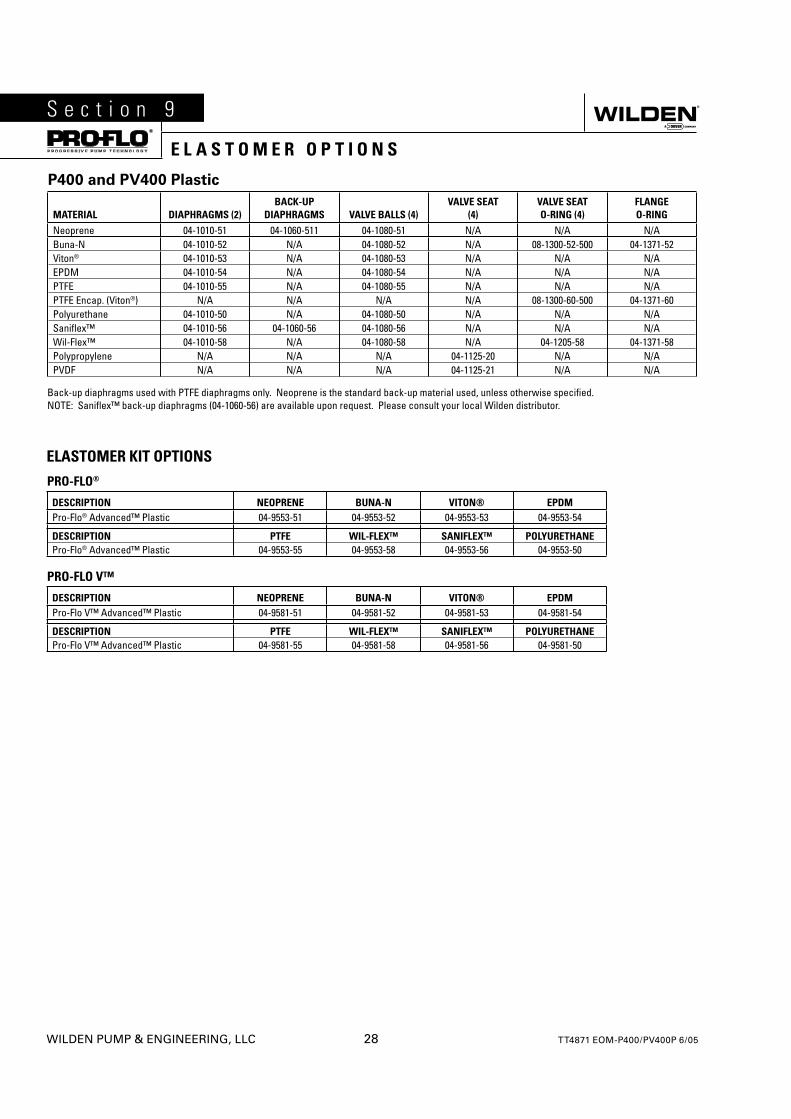
P400 and PV400 Plastic
MATERIAL DIAPHRAGMS (2)BACK-UP
DIAPHRAGMS VALVE BALLS (4)VALVE SEAT
(4)VALVE SEAT O-RING (4)
FLANGEO-RING
Neoprene 04-1010-51 04-1060-511 04-1080-51 N/A N/A N/ABuna-N 04-1010-52 N/A 04-1080-52 N/A 08-1300-52-500 04-1371-52Viton® 04-1010-53 N/A 04-1080-53 N/A N/A N/AEPDM 04-1010-54 N/A 04-1080-54 N/A N/A N/APTFE 04-1010-55 N/A 04-1080-55 N/A N/A N/APTFE Encap. (Viton®) N/A N/A N/A N/A 08-1300-60-500 04-1371-60Polyurethane 04-1010-50 N/A 04-1080-50 N/A N/A N/ASanifl ex™ 04-1010-56 04-1060-56 04-1080-56 N/A N/A N/AWil-Flex™ 04-1010-58 N/A 04-1080-58 N/A 04-1205-58 04-1371-58Polypropylene N/A N/A N/A 04-1125-20 N/A N/APVDF N/A N/A N/A 04-1125-21 N/A N/A
Back-up diaphragms used with PTFE diaphragms only. Neoprene is the standard back-up material used, unless otherwise specifi ed.NOTE: Sanifl ex™ back-up diaphragms (04-1060-56) are available upon request. Please consult your local Wilden distributor.
ELASTOMER KIT OPTIONS
PRO-FLO®
DESCRIPTION NEOPRENE BUNA-N VITON® EPDM Pro-Flo® Advanced™ Plastic 04-9553-51 04-9553-52 04-9553-53 04-9553-54
DESCRIPTION PTFE WIL-FLEX™ SANIFLEX™ POLYURETHANE Pro-Flo® Advanced™ Plastic 04-9553-55 04-9553-58 04-9553-56 04-9553-50
PRO-FLO V™
DESCRIPTION NEOPRENE BUNA-N VITON® EPDM Pro-Flo V™ Advanced™ Plastic 04-9581-51 04-9581-52 04-9581-53 04-9581-54
DESCRIPTION PTFE WIL-FLEX™ SANIFLEX™ POLYURETHANE Pro-Flo V™ Advanced™ Plastic 04-9581-55 04-9581-58 04-9581-56 04-9581-50
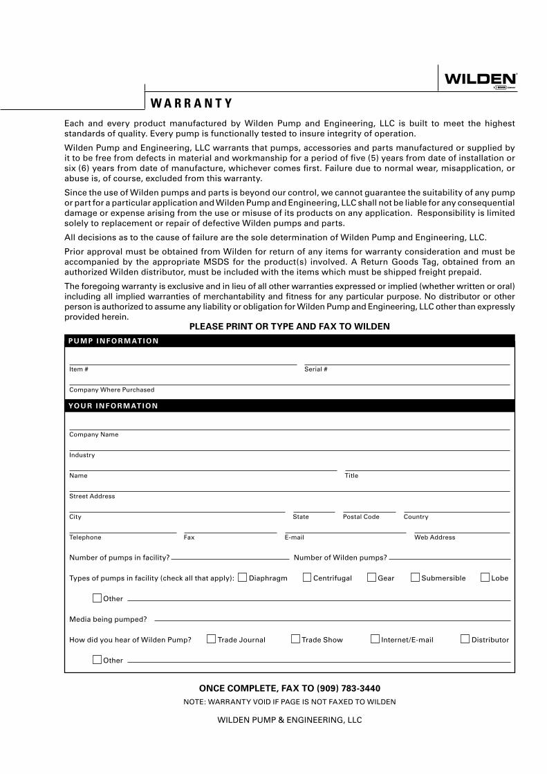
Item # Serial #
Company Where Purchased
Company Name
Industry
Name Title
Street Address
City State Postal Code Country
Telephone Fax E-mail Web Address
Number of pumps in facility? Number of Wilden pumps?
Types of pumps in facility (check all that apply): Diaphragm Centrifugal Gear Submersible Lobe
Other
Media being pumped?
How did you hear of Wilden Pump? Trade Journal Trade Show Internet/E-mail Distributor
Other
P U M P I N F O R M AT I O N
PLEASE PRINT OR TYPE AND FAX TO WILDEN
YO U R I N F O R M AT I O N
ONCE COMPLETE, FAX TO (909) 783-3440
NOTE: WARRANTY VOID IF PAGE IS NOT FAXED TO WILDEN
WILDEN PUMP & ENGINEERING, LLC
W A R R A N T YEach and every product manufactured by Wilden Pump and Engineering, LLC is built to meet the highest standards of quality. Every pump is functionally tested to insure integrity of operation.
Wilden Pump and Engineering, LLC warrants that pumps, accessories and parts manufactured or supplied by it to be free from defects in material and workmanship for a period of fi ve (5) years from date of installation or six (6) years from date of manufacture, whichever comes fi rst. Failure due to normal wear, misapplication, or abuse is, of course, excluded from this warranty.
Since the use of Wilden pumps and parts is beyond our control, we cannot guarantee the suitability of any pump or part for a particular application and Wilden Pump and Engineering, LLC shall not be liable for any consequential damage or expense arising from the use or misuse of its products on any application. Responsibility is limited solely to replacement or repair of defective Wilden pumps and parts.
All decisions as to the cause of failure are the sole determination of Wilden Pump and Engineering, LLC.
Prior approval must be obtained from Wilden for return of any items for warranty consideration and must be accompanied by the appropriate MSDS for the product(s) involved. A Return Goods Tag, obtained from an authorized Wilden distributor, must be included with the items which must be shipped freight prepaid.
The foregoing warranty is exclusive and in lieu of all other warranties expressed or implied (whether written or oral) including all implied warranties of merchantability and fi tness for any particular purpose. No distributor or other person is authorized to assume any liability or obligation for Wilden Pump and Engineering, LLC other than expressly provided herein.