manual: 6888a o2 combustion flue gas transmitter · because these instruments are sophisticated...
TRANSCRIPT
Instruction ManualCMB-MAN-6888A
June 2017
RosemountTM 6888A O2 CombustionFlue Gas Transmitter

This manual contains instructio
B

NOTES
Emerson designs, manufactures and tests its products to meet many national and internationalstandards. Because these instruments are sophisticated technical products, you MUST properlyinstall, use, and maintain them to ensure they continue to operate within their normal specifica-tions. The following instructions MUST be adhered to and integrated into your safety programwhen installing, using, and maintaining Rosemount products. Failure to follow the proper instruc-tions may cause any one of the following situations to occur: Loss of life; personal injury; propertydamage; damage to this instrument; and warranty invalidation.• Read all instructions prior to installing, operating, and servicing the product.• If you do not understand any of the instructions, contact your Emerson representative for clari-
fication.• Follow all warnings, cautions, and instructions marked on and supplied with the product.• Inform and educate your personnel in the proper installation, operation, and maintenance of the
product.• Install your equipment as specified in the Installation Instructions of the appropriate Instruction
Manual and per applicable local and national codes. Connect all products to the proper electricaland pressure sources.
• To ensure proper performance, use qualified personnel to install, operate, update, program, andmaintain the product.
• When replacement parts are required, ensure that qualified people use replacement parts spec-ified by Emerson. Unauthorized parts and procedures can affect the product's performance,place the safe operation of your process at risk, and VOID YOUR WARRANTY. Look-alike substi-tutions may result in fire, electrical hazards, or improper operation.
• Ensure that all equipment doors are closed and protective covers are in place, except whenmaintenance is being performed by qualified persons, to prevent electrical shock and personalinjury.
The information contained in this document is subject to change without notice.
The 375 Field Communicator must be upgraded to System Software 2.0 with Graphic License for opera-tion with the 6888A O2 Transmitter. The AMS software must be upgraded to AMS 8.0 or above.Contact Emerson’s Global Service Center (GSC) at 1-800-833-8314 to upgrade the 375 FieldCommunicator software to System Software 2.0 with Graphic License.
Essential InstructionsRead this page before proceeding
Essential Instructions I
This manual contains instructions for installation and operation of the 6888A O2 CombustionFlue Gas Transmitter. The following list provides notes concerning all revisions of this document.
Rev. Level Date NotesA 8/2013 This is the initial release of the product manual. The manual
has been reformatted to reflect the Emerson documentation style and updated to reflect any changes in the product offering.
B 4/2017 Updated Rosemount and Emerson logos, URLs, and address on back page.
C 6/2017 Added Appendix C - Product Certifications.
About this document
II

6888A O2 Combustion Flue Gas Transmitter Manual Table of ContentsCMB_MAN_6888A June 2017
ContentsEssential Instructions......................................................................................................I
Section i: IntroductionPreface..........................................................................................................................1
Definitions ....................................................................................................................1
Symbols........................................................................................................................2
Overview ......................................................................................................................2
Technical Support Hotline ............................................................................................2
Section 1: Description and Specifications1.1 Component Checklist...................................................................................................3
1.2 Technical Support Hotline ............................................................................................4
1.3 System Overview..........................................................................................................4
1.4 System Configurations .................................................................................................4
1.5 Probe Options ..............................................................................................................8
1.6 6888A Product Matrix ................................................................................................10
1.7 6888Xi Product Matrix ...............................................................................................12
1.8 Transmitter/DR Probe Specifications..........................................................................13
1.9 Transmitter Specifications..........................................................................................17
Section 2: Installation2.1 System Considerations...............................................................................................19
2.2 Mechanical Installation...............................................................................................20
2.3 Electrical Installation ..................................................................................................26
2.4 Pneumatic Installation................................................................................................42
Section 3: Configuration, Startup and Operation3.1 Powering Up 6888 Transmitter without 6888Xi ........................................................47
3.2 Powering Up 6888 Transmitter With Single/Dual Channel or Single Channel & Flame ..Safety Interlock 6888Xi ..............................................................................................47
3.3 6888 Direct Replacement Probe (no electronics inside) with Traditional Architecture ..6888Xi........................................................................................................................48
3.4 6888Xi Quick Start Wizard .........................................................................................48
3.5 Re-initiating 6888Xi Wizard........................................................................................49
3.6 Calibration..................................................................................................................49
3.7 System Parameter Descriptions .................................................................................76
3.8 Parameter Setup ........................................................................................................78
3.9 Calibration..................................................................................................................80
3.10 D/A Trim .....................................................................................................................82
Section 4: Troubleshooting4.1 Overview ....................................................................................................................854.2 General.......................................................................................................................86
4.3 Alarm Indications .......................................................................................................86Table of Contents III

Table of Contents 6888A O2 Combustion Flue Gas Transmitter ManualJune 2017 CMB_MAN_6888A
4.4 Identifying and Correcting Fault Indications...............................................................87
4.5 Calibration Passes, But Still Reads Incorrectly.............................................................87
Section 5: Maintenance and Service5.1 Overview ....................................................................................................................93
5.2 Maintenance Intervals ................................................................................................93
5.3 Calibration..................................................................................................................94
5.4 6888A Repair..............................................................................................................94
5.5 Removal and Replacement of Probe...........................................................................94
5.6 Transmitter Board Replacement.................................................................................95
5.7 DR Terminal Board Replacement ................................................................................97
5.8 Heater Strut Replacement ..........................................................................................98
5.9 Cell Replacement......................................................................................................100
5.10 Diffusion Element Replacement ...............................................................................102
5.11 Blind Cover Replacement..........................................................................................103
Section 6: Replacement Parts6.1 6888A Transmitter ...................................................................................................105
Section 7: Optional Accessories7.1 Asset Management Solutions (AMS) ........................................................................107
7.2 By-Pass Packages......................................................................................................107
7.3 SPS 4001B Single Probe Autocalibration Sequencer ................................................108
7.4 IMPS 4000 Intelligent Multiprobe Test Gas Sequencer. ............................................109
7.5 O2 Calibration Gas. ...................................................................................................110
7.6 OxyBalance Display and Averaging System..............................................................110
Appendix A: Safety DataA.1 Safety Instructions ...................................................................................................111
Appendix B: Return of MaterialB .1 Returning Material....................................................................................................133
Appendix C: Product CertificationsC .1 European Directive Information ...............................................................................135
C .2 Ordinary Location Certification ................................................................................135
C .3 Installing Equipment in North America ....................................................................135
C .4 Rosemount 6888A In-Situ Oxygen Transmitter for General Purpose Locations .......135
IV Table of Contents

6888A O2 Combustion Flue Gas Transmitter Manual Table of ContentsCMB_MAN_6888A June 2017
Table of Contents V

VI Table of Contents
Table of Contents 6888A O2 Combustion Flue Gas Transmitter ManualJune 2017 CMB_MAN_6888A

6888A O2 Combustion Flue Gas Transmitter Manual Section i: IntroductionCMB_MAN_6888A June 2017
Introduction 1
PrefaceThe purpose of this manual is to provide information concerning components, functions, instal-lation and maintenance of the 6888A O2 Transmitter.
Some sections may describe equipment not used in your configuration. The user should becomethoroughly familiar with the operation of this module before operating it. Read this instructionmanual completely.
DefinitionsThe following definitions apply to WARNINGS, CAUTIONS, and NOTES found throughout thispublication.
Section i: Introduction
WARNING
Highlights an operation or maintenance procedure, practice, condition, statement, etc. If not strictlyobserved, could result in injury, death, or long-term health hazards of personnel.
CAUTION
Highlights an operation or maintenance procedure, practice, condition, statement, etc. If not strictlyobserved, could result in damage to or destruction of equipment, or loss of effectiveness.
NOTE
Highlights an essential operating procedure, condition, or statement.

Symbols
OverviewThe 6888A is Rosemount's latest in-situ probe offering intended for combustion flue gas service.Similar to our previous World Class and Oxymitter probes, there is no sampling system. The sens-ing cell is mounted to the end of a probe (18", 3', 6’, 9’, or 12’ long) that is directly inserted intothe flue gas stream.
The sensing cell is of similar design to the World Class and Oxymitter cells, utilizing the zirconiumoxide sensing principle. The cell is heated and maintained at a 736°C (1357°F) setpoint, and gen-erates a logarithmic MV signal proportional to the partial pressure difference of oxygen betweenthe reference side of the cell (usually instrument air at 20.95% O2), and the process side of thecell (usually combustion flue gasses). For more information on sensing cell operation, see theOverview of Operating Principles in Section 4: Troubleshooting.
Technical Support HotlineFor assistance with technical problems, please call the Customer Support Center (CSC).
Phone: 1-800-433-6076 1-440-914-1261
In addition to the CSC, you may also contact Field Watch. Field Watch coordinates Emerson’sfield service throughout the U.S. and abroad.
Phone: 1-800-654-RSMT (1-800-654-7768)
e-mail: [email protected]
web: www.Emerson.com/RosemountGasAnalysis
2 Introduction
Section i: Introduction 6888A O2 Combustion Flue Gas Transmitter ManualJune 2017 CMB_MAN_6888A
RISK OF ELECTRICAL SHOCK
WARNING: REFER TO INSTRUCTION MANUAL
PROTECTIVE CONDUCT OR TERMINAL
EARTH (GROUND) TERMINAL:
:
:
:
NOTE
The number in the lower right corner of each illustration in this publication is a manual illustrationnumber. It is not a part number, and is not related to the illustration in any technical manner.

1.1 Component ChecklistA typical Rosemount 6888A O2 Combustion Flue Gas Transmitter should contain the items shownin Figure 1-1. A complete Oxygen Analyzer system will include some or all of the equipmentshown. However, this manual describes the 6888A Transmitter only. Record the part number, seri-al number, and order number for the 6888A Transmitter in the table located on the back cover ofthis manual.
Also, use the product matrix (Table 1-1) at the end of this section to compare your order numberagainst your unit. The first part of the matrix defines the model. The last part defines the variousoptions and features of the 6888A. Ensure the features and options specified by your order num-ber are on or included with the unit.
Section 1: Description and Specifications
Description and Specifications 3
6888A O2 Combustion Flue Gas Transmitter Manual Section 1: Description and SpecificationsCMB_MAN_6888A June 2017
Figure 1-1. Typical System Package
Optional 6888Xi Advanced Electronics
Full InstructionManual DVD
6888A Probe with StandardTerminations/ElectronicsHousing
6888A Integral Autocal Housing
Optional TraditionalArchitecture Cable
Optional Mounting orAdapter Plate
Optional Reference& Calibration GasAccessories
Quick StartManual

4 Description and Specifications
Section 1: Description and Specifications 6888A O2 Combustion Flue Gas Transmitter ManualJune 2017 CMB_MAN_6888A
1.2 Technical Support HotlineFor assistance with technical problems, please call the Customer Support Center (CSC).
• 1-RAI-AND-U (1-855-724-2638)
• 1-440-914-1261
In addition to the CSC, you may also contact Field Watch. Field Watch coordinates Emerson’sfield service throughout the U.S. and abroad.
•1-800-654-RSMT (1-800-654-7768)
Emerson may also be reached via the Internet through e-mail and the World Wide Web
• e-mail: [email protected]
•World Wide Web: www.Emerson.com/RosemountGasAnalysis
1.3 System OverviewThe 6888 is Rosemount’s latest combustion flue gas oxygen analyzer. This product is intendedfor measuring the flue gases resulting from any combustion process. It utilizes the same heatedsensing technology as the O2 sensors found in most automobiles. Contact RosemountAnalytical’s technical support group at 800-433-6076 for any applications other than measuringcombustion flue (exhaust) gases.
This product utilizes an “in situ” sensor, i.e. the sensor is placed at the end of a probe, and theprobe extends directly into the flue gas duct or stack at a given length. The sensor is like a ther-mocouple, generating it’s own millivolt signal based on the difference between a reference gas(ambient or instrument air – always 20.95% O2), and the flue gases being measured. There areseveral different arrangements of probes, electronics, and features that are explained below, andin the wiring diagrams.
An optional 6888 Xi with HART communications provides convenient operator interface for set-up, calibration, and diagnostics. HART communications is still present when using the 6888Xi.
1.4 System Configurations
1.4.1 Transmitter Probe, OnlyThe 6888 probe has the electronics in the blue housing that controls the heater temperature,and also amplifies the raw O2 millivolt signal to a linear 4-20 mA. The 4-20 mA signal lines can berun directly to the control room, and also powers the transmitter electronics. As with most otherRosemount transmitters measuring pressure, temperature, and flow, set-up is conductedthrough HART communications via a 475 handheld communicator, or via Asset ManagementSolutions (AMS).
1.4.2 Standard Housing Transmitter Probe plus 6888Xi ElectronicsThe 6888Xi electronics serve as a local operator interface unit, with a back-lit display and keypad. It iscapable of two channels, serving two 6888 probes. The 6888Xi also carries these optional advancedfeatures:
• Fully automatic calibration. Requires Xi 02 Cal Auto calibration system.

Description and Specifications 5
6888A O2 Combustion Flue Gas Transmitter Manual Section 1: Description and SpecificationsCMB_MAN_6888A June 2017
• Loss-of flame contact for powering down the heater in the event of a flame-out condi-tion in a furnace.
• Heaterless operation at process temperatures above 550°C. This feature will also permitoperation above the heater set point of 736°C. Sensing cell life will be shortened byoperation above 800°C, however.
• Plugged diffuser diagnostic operates by measuring the return-to-process rate aftercalibration gas has been stopped. This feature also includes auto gas switching whenthe reading settles out versus waiting for configured gas flow time to expire.
• Stoichiometer – If a furnace goes into a reducing condition (zero % O2), this feature willdetermine how far.
• Programmable reference – Permits more accurate readings at near-ambient O2 levels(20.95% O2).
• A “cal check” capability. New calibration values are not automatically stored after a calibra-tion. An accept/reject calibration feature can be enabled or disabled so that the technician oroperator can decide to accept or reject a potentially large change in calibration values.
• Tolerance Check that will alarm if the wrong test gases are being used, or if a bottle runs outin the middle of a calibration. Care must be taken to ensure gas 1 and gas 2 calibration gasesare properly configured if the tolerance check feature is enabled.
1.4.3 Transmitter Probe and 6888Xi with Flame safety interlockA flame safety interlock by Emerson is available for heater power disconnect whenever there is a loss ofthe process flame or a heater runaway condition (heater over-temperature) in the O2 Probe. This inputis internally powered by the 6888Xi and is actuated via a dry contact output from the user’s flamescanner. A closed contact indicates a flame is present. An open contact indicates a loss of flame. Thisfeature is also available with the Integral autocal housing.
1.4.4 Transmitter Probe with Integral Autocal, 6888Xi, and HART communications
This probe contains gas-switching solenoids so that the 6888Xi electronics can control the introduc-tion of calibration gases. Calibrations can be initiated via a calibration recommended diagnostic, timesince last calibration, manually via external dry contact, HART communications, or from the 6888Xilocal operator interface keypad. The integral autocal feature can only be implemented when the probeis used with a 6888Xi.
1.4.5 Transmitter Probe with Integral Autocal and FOUNDATION Fieldbus (FF) communications
This probe contains gas-switching solenoids that can control the introduction of calibration gases forcalibration. Calibrations can be initiated automatically via a calibration recommended diagnostic, timesince last calibration, or manually via optional Xi keypad, FF communications via the 475communicator, or AMS console. Unlike the HART transmitter electronics, the FF version can executeautomatic calibrations either with or without the optional 6888 Xi electronics. Likewise, advancedfeatures can be implemented either with or without the optional Xi.
1.4.6 Direct Replacement (DR) Probe, with Traditional Architecture 6888Xi electronics
Here there are no electronics inside the probe head, so the raw sensor signals for the heater

6 Description and Specifications
Section 1: Description and Specifications 6888A O2 Combustion Flue Gas Transmitter ManualJune 2017 CMB_MAN_6888A
thermocouple and zirconium oxide O2 sensor are sent to a remote 6888Xi Electronics. The 6888Traditional Architecture electronics will also directly apply power to the probe heater in order tomaintain the correct sensor temperature. This arrangement calls for a 7- conductor cable to carry thispower and the sensor signals. Maximum length for this cable is 200 feet. This probe will also operate onprevious Westinghouse/Rosemount electronics (World Class and Oxymitter), as well as manycompetitive electronics.
1.4.7 Wireless CapabilityIt should be noted that both the transmitter electronics in the head of the probe and the 6888Xielectronics communicate over HART communications, and can implement wireless communicationsvia our Smart Wireless THUM adapter.
1.4.8 Automatic Calibration
Calibrations consist of introducing bottled gases of known value into the probe so theelectronics can make automatic adjustments to the O2 readings to match the bottled gas value.0.4% O2 and 8% O2 (balance nitrogen) gases are recommended. Never use nitrogen orinstrument air as calibration gases. Flowmeters (for calibration gases) and regulators andflowmeters (for reference air) are available as loose components, mounted into an optionalmanual calibration switching panel, or as a fully automatic calibration system (Figure 1-5) wherecalibration solenoids are switched from the 6888Xi Advanced Electronics. See IM-106-340AC,SPS 4000B Single Probe Autocalibration Sequencer or IM-106-400IMPS, IMPS 4000 IntelligentMultiprobe Test Gas Sequencer, for additional details.
1.4.9 Communication Options
6888A communications are accomplished by a customer-supplied 375/475 Field Communicatorand/or the optional 6888Xi Advanced Electronics. Graphic displays are available via the optionalOxyBalance Display and Averaging System.
Data CommunicationsAn operator can configure and diagnostically troubleshoot the 6888A in one of two ways:
1. Using the optional 6888Xi Advanced Electronics allows local communication with the elec-tronics. The 6888Xi also carries the following optional advanced features:
• Fully automatic calibration
• Optional flame safety interface (single probe version only)
• High temperature operation [above 700°C (1292°F) standard temperature].
• Stoichiometer feature provides the ability to indicate O2 efficiency when the combustionprocess goes into reducing conditions (0% O2).
• Programmable reference provides enhanced accuracy when measuring at or near O2
level (20.95% O2).
• Plugged diffuser diagnostic to detect fouled diffuser.
2. Using the HART Interface, the 6888A's 4-20 mA output line transmits an analog signal pro-portional to the oxygen level. The HART output is superimposed on the 4-20 mA output line.This information can be accessed through the following:

• Rosemount 375/475 Field Communicator - The handheld communicator requires DeviceDescription (DD) software specific to the 6888A. The DD software will be supplied withmany 375/475 units but can also be programmed into existing units at most Emersonservice offices. See Section 3, Startup and Operation, for additional information.
• Personal Computer (PC) - The use of a personal computer requires AMS software avail-able from Emerson.
• Delta V and Ovation Distributed Control System (DCS) with AMS-inside capability.
3. The 6888A can also transmit HART information wirelessly via a wireless THUM Adapter, TheTHUM Adapter threads into the 6888A conduit port and converts the 4-20 mA O2 signal to awireless protocol. All other HART information is also transmitted.
In addition to the wireless THUM Adapter, a hard-wire connection of the 4-20 mA signal tothe DCS may be used at the same time. More detailed information regarding the applicationof the THUM Adapter is available in Product Data Sheet 00813-0100-4075.
Description and Specifications 7
6888A O2 Combustion Flue Gas Transmitter Manual Section 1: Description and SpecificationsCMB_MAN_6888A June 2017
Figure 1-5. 6888A with 6888Xi Advanced Electronics and Autocalibration Sequencer
NOTE
The 375 Field Communicator must be upgraded to System Software 2.0 with Graphic License foroperation with the 6888A O2 Transmitter. The AMS software must be upgraded to AMS 8.0 or above.
Contact Emerson Global Service Center (GSC) at 1-800-833-8314 to upgrade the 375 FieldCommunicator software to System Software 2.0 with Graphic License.

38890063
Analytical
AAnAnaAnalAnalyAnalyt
Analyti
Analytic
Analytica
Analytical
8 Description and Specifications
Section 1: Description and Specifications 6888A O2 Combustion Flue Gas Transmitter ManualJune 2017 CMB_MAN_6888A
Optional OxyBalance Display and Averaging SystemReceives up to eight 4-20 mA signals from individual probes. Trends individual outputs and calcu-lates four programmable averages as additional 4-20 mA outputs. OxyBalance graphic displaysare shown in Figure 1-6. See IM-106-4050, OxyBalance Oxygen Display and Averaging System,for additional details.
1.5 Probe Options
1.5.1 Diffusion ElementsThe 6888A is available with one of three diffusion elements fitted to the process end. The basicdiffusers provide for a constant outer probe tube diameter the full length of the probe. When the6888A is used with an abrasive shield, the diffuser body has a larger diameter with grooves toaccept packing material to seal out fly ash. The snubber and ceramic diffusers may also be fittedwith a flash arrestor to reduce the possibility of the probe from igniting flammable gases withinthe process.
Snubber Diffusion AssemblyThe standard snubber diffusion assembly (Figure 1-7) is satisfactory for most applications, howev-er the snubber diffuser should not be used in flue gas temperatures above 400°C (752°F).
Figure 1-6. OxyBalance displays
WARNING
The diffusers fitted with flash arrestors have been tested to provide a measure or protection in preventing ignition of flammable gases. They are not intended to provide flame proof or explosion proof protection for the 6888A.
Description and Specifications 9
6888A O2 Combustion Flue Gas Transmitter Manual Section 1: Description and SpecificationsCMB_MAN_6888A June 2017
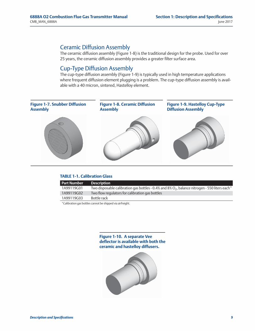
Ceramic Diffusion AssemblyThe ceramic diffusion assembly (Figure 1-8) is the traditional design for the probe. Used for over25 years, the ceramic diffusion assembly provides a greater filter surface area.
Cup-Type Diffusion AssemblyThe cup-type diffusion assembly (Figure 1-9) is typically used in high temperature applicationswhere frequent diffusion element plugging is a problem. The cup-type diffusion assembly is avail-able with a 40 micron, sintered, Hastelloy element.
Figure 1-7. Snubber DiffusionAssembly
Figure 1-8. Ceramic DiffusionAssembly
Figure 1-9. Hastelloy Cup-TypeDiffusion Assembly
Part Number Description1A99119G01 Two disposable calibration gas bottles - 0.4% and 8% O2, balance nitrogen - 550 liters each*1A99119G02 Two flow regulators for calibration gas bottles1A99119G03 Bottle rack*Calibration gas bottles cannot be shipped via airfreight.
TABLE 1-1. Calibration Glass
Figure 1-10. A separate Veedeflector is available with both theceramic and hastelloy diffusers.

10 Description and Specifications
Section 1: Description and Specifications 6888A O2 Combustion Flue Gas Transmitter ManualJune 2017 CMB_MAN_6888A
1.6 6888A Product MatrixCompare the configuration matrix below to the model number on the probe tag to confirm thefeatures present in this specific probe.
* Probes supplied with flanges with dual ANSI/DIN hole pattern. See Figure 3 for details.
Model Description
6888A O2 Transmitter
Measurement
1OXY Oxygen, Standard Sensing Cell
2OXY Oxygen, Acid Resistant Stoichiometric Sensing Cell
Probe Length*
1 18" Probe, Standard Probe Tube
2 18" Probe, Standard Probe Tube with Abrasive Shield
3 18" Probe, Abrasion Resistant Probe Tube
4 3' Probe, Standard Probe Tube
5 3' Probe, Standard Probe Tube with Abrasive Shield
6 3' Probe, Abrasion Resistant Probe Tube
7 6' Probe, Standard Probe Tube
8 6' Probe, Standard Probe Tube with Abrasive Shield
9 6' Probe, Abrasion Resistant Probe Tube
A 9' Probe, Abrasion Resistant Probe Tube
AA 9' Probe, Abrasion Resistant Probe Tube with Abrasive Shield
B 12' Probe, Abrasion Resistant Probe Tube
BA 12' Probe, Abrasion Resistant Probe Tube with Abrasive Shield
Diffuser
1 Snubber 400°C (752°F)
1A Snubber with dust shield 400°C (752°F) (Used with Abrasive Shield)
1F Snubber with Flashback Arrestor 400°C (752°F)
2 Ceramic 825°C (1517°F)
2A Ceramic with dust shield 825°C (1517°F) (Used with Abrasive Shield)
2F Ceramic (825°C) with Flashback Arrestor 825°C (1517°F)
3 Hastelloy 40 um 705°C (1292°F)
3A Hastelloy with dust seal 40 um 705°C (1292°F) (Used with Abrasive Shields)
Housing & Electronics
1HT Standard Housing, Transmitter Electronics, HART Communications
2HT Integral Autocal, Transmitter Electronics, HART Communications
4FF Integral Autocal, Transmitter Electronics, Fieldbus Communications
5DR Standard Housing, Direct Replacement, No Electronics
6DRY Standard Housing, Direct Replacement, YEW Electronics

Description and Specifications 11
6888A O2 Combustion Flue Gas Transmitter Manual Section 1: Description and SpecificationsCMB_MAN_6888A June 2017
Mounting Plate
00 None
04 New Installation - Square Weld Plate with ANSI 2" - 150# Studs & Flange (2.5" process hole required)
05 New Installation - Square Weld Plate with DIN Studs & Flange (2.5" process hole required)
06 New Installation - Variable Insertion Mount; Abrasion Resistant Probe Only
07 New Installation - Variable Insertion Mount; Mounted to Existing OXT/WC Abrasive Shield Mounts; Abrasion Resistant Probe Only
08 Adapter to Existing ANSI 3", 150# Flange
09 Adapter to Existing ANSI 4", 150# Flange
10 Adapter to Existing ANSI 6", 150# Flange
11 Adapter to Existing ANSI 3", 300# Flange
12 Adapter to Existing ANSI 4", 300# Flange
99 Special Adapter - provide existing flange dimensions, including thru-hole diameter
Manual Calibration Accessories
00 None
01 Calibration & Reference Gas Flowmeters & Reference Regulator/Filter Diffuser
02 Calibration/Reference Panel
Stoichiometer Function - FOUNDATION Fieldbus only (For HART versions, order this feature with 6888 Xi electronics)
0 No
1 Yes
Programmable Reference Function - FOUNDATION Fieldbus only (For HART versions, order this feature with6888 Xi electronics)
0 No
1 Yes
Extended Temperature Reference Function - FOUNDATION Fieldbus only (For HART versions, order thisfeature with 6888 Xi electronics)
0 No
1 Yes
Diffuser Warning Function - FOUNDATION Fieldbus only (For HART versions, order this feature with6888 Xi electronics)
0 No
1 Yes

12 Description and Specifications
Section 1: Description and Specifications 6888A O2 Combustion Flue Gas Transmitter ManualJune 2017 CMB_MAN_6888A
1.7 6888Xi Product MatrixCompare the configuration matrix below to the model number on the probe tag to confirm thefeatures present in this specific probe.
Model Product Description
6888Xi Advanced Electronics
Remote Type
1OXY Single Channel O2
2OXY Single Channel O2 with Flame Safety Interlock for Heater
30XY Dual Channel O2
40XY Single Channel O2, Traditional Architecture for 120V Probes*
Mounting
00 No Hardware
01 Panel Mount Kit with Gasket
02 2" Pipe / Wall Mount Kit
Cable
00 No Cable
10 20' (6m) Cable, use with Traditional Architecture Probe only
11 40' (12m) Cable use with Traditional Architecture Probe only
12 60' (18m) Cable use with Traditional Architecture Probe only
13 80' (24m) Cable use with Traditional Architecture Probe only
14 100' (30m) Cable use with Traditional Architecture Probe only
15 150' (45m) Cable use with Traditional Architecture Probe only
16 200' (60m) Cable use with Traditional Architecture Probe only
Stoichiometer Function for O200 No
01 Single Channel
02 Dual Channel
Programmable Reference Function for O2
00 None
01 Single Channel
02 Dual Channel
Extended Temperature Function for O2
00 None
01 Single Channel
02 Dual Channel
Plugged Diffuser Diagnostics
00 None
01 Single Channel
02 Dual Channel
*Note: The 6888 Xi does not support World Class 44v probes. The X-STREAM Xi will support World Class 44v probes.

Description and Specifications 13
6888A O2 Combustion Flue Gas Transmitter Manual Section 1: Description and SpecificationsCMB_MAN_6888A June 2017
1.8 Transmitter/DR Probe Specifications
1.8.1 Measurement SpecificationsNet O2 RangeVariable 0-10% to 0-50%(Xi electronics off 0-50% O2 range)
Accuracy in Oxidizing Conditions±0.75% of reading or 0.05%2 whichever is greater
Lowest Detectable Limit0.02% O2
Process Temperature EffectLess than 0.05% O2 from 100° to 700°C (212° to 1292°F)
System Speed of Response to Calibration GasInitial response in less than 3 seconds T∞ in less than 8 seconds. Response to process gaschanges will vary depending on process gas velocity and particulate loading of the diffuser
Calibration ValidityPresentation of calibration gases matches the bottle value to within ±0.02% O2
Accuracy in Reducing Conditions (requires stoichiometer feature)±10% of reading or 0.1% O2, whichever is greater
System Response in Reducing Conditions (requires stoichiometer feature)Going from oxidizing to reducing -T90 in 120 secondsGoing from reducing to oxidizing -T90 in 30 seconds
1.8.2 Environmental Specifications
Transmitter ProbeTransmitter ProbeProcess-wetted materials are 316L or 304 Stainless
Process Temperature Limits0° to 705°C (32° to 1300°F)550° to 825°C (1022° to 1517°F)* with Xi “heaterless operation” feature**Reduced cell life can be expected if operated continuously at temperaturesabove 705°C (1300°F)optional bypass and jacket accessories permit operation to 1050°C (1922°F)
Probe electronicsProbe electronics ambient temperature limits-40° to 70°C (-40° to 158°F)
Temperature limit as measured inside probe electronics-40° to 85°C (-40° to 185°F)
DR probe, no electronics inside, ambient temperature limits-40° to 90°C (-40° to 194°F)

14 Description and Specifications
Section 1: Description and Specifications 6888A O2 Combustion Flue Gas Transmitter ManualJune 2017 CMB_MAN_6888A
Optional Xi electronicsNEMA 4X, Polycarbonate Material
General Purpose Certifications
Xi Ambient temperature limits-20°C to 50°C (-4°F to 122°F)
Xi Temperature Limits as Measured Inside the Electronics Housing-20°C to 70°C (-4°F to 158°F)
1.8.3 Installation Specifications - ProbeProbe Mounting FlangeVertical or horizontal–2" 150# (4.75" (121mm) bolt circle)
Note: Flanges are flat-faced and for mounting only. Flanges are not pressure-rated. A 2.5" diame-ter hole in the process is required.
Spool piece P/N 3D39761G02 is available to offset probe electronics housing from hot ductwork.
Many adapter flanges are available to mate to existing flanges.
Probe Lengths and Approximate Shipping Weights
18 in (457 mm) package 16 pounds (7.3 Kg)3 foot (0.91 m) package 21 pounds (9.5 Kg)6 foot (1.83 m) package 27 pounds (12.2 Kg)9 foot (2.74 m) package 33 pounds (15.0 kg)12 foot (3.66 m) package 39 pounds (17.7 kg)
Reference Air (optional)2 scfh (1 l/min), clean, dry, instrument-quality air (20.95% O2) regulated to 5 psi (34 kPa)
CalibrationSemi-automatic or automatic
Cal Gases0.4% O2 and 8% O2, balance N2 recommended. Instrument air may be used as a high cal gas butis not recommended.
100% nitrogen cannot be used as the low cal gas.
Calibration Gas Flow5 scfh (2.5l/min)
Heater Electrical Power120/240V ±10%, 50/60 Hz, 1/2 in.–14NPT conduit ports
Traditional Architecture Cable200 foot (61m) maximum length
Power Consumption of Probe Heater776 VA maximum during warm-up

6888A O2 Combustion Flue Gas Transmitter Manual Section 1: Description and SpecificationsCMB_MAN_6888A June 2017
1.8.4 Installation Specifications Xi with Transmitter ProbeElectrical Power of Optional Xi Electronics120/240V ±10%, 50/60 Hz,
Power Consumption of Xi10 watts maximum
Xi Alarms Relays2 provided - 2 amps, 30 VDC
Xi Optional Loss of Flame ContactRemoves heater power
Electrical NoiseMeets EN 61326, Class A
Traditional Architecture Cable200 ft (61m) maximum length
Transmitter Electrical 4-20 mA Power12 - 42VDC, (looped-powered from the control room or from the Xi box)
Description and Specifications 15

16 Description and Specifications
Section 1: Description and Specifications 6888A O2 Combustion Flue Gas Transmitter ManualJune 2017 CMB_MAN_6888A
1.8.5 Installation Specifications for Traditional Architecture Xi for use with DR or other Probe
Electrical Power for Xi120/240V ±10%, 50/60 Hz
Power Consumption of Xi12 VA maximum or 1020 VA maximum with Traditional Architecture, 120V Probes.450 VA maximum with Traditional Architecture 44V Probes
Alarm Relay OutputsTwo provided - 2 Amperes, 30 VDC, Form-C
Optional Loss of Flame InputInternally powered input to remove heater power actuated via dry contact output from prove offlame device.
Emerson has satisfied all obligations coming fromthe European legislation to harmonize the product requirements in Europe.

Description and Specifications 17
6888A O2 Combustion Flue Gas Transmitter Manual Section 1: Description and SpecificationsCMB_MAN_6888A June 2017
1.9 Transmitter Specifications
1.9.1 Measurement SpecificationsNet O2 Range: 0 to 50% O2 user scalable, -2 to 50% O2 user scalable with stoichiometer
Accuracy in Oxidizing Conditions: ±0.75% of reading or 0.05% O2 whichever is greater
Lowest Detectable Limit: 0.01% O2
Signal Stability: ±0.03% O2
Process Temperature Effect: less than 0.05% O2 from 100° to 700°C (212° to 1292°F)
System Speed of Response to Calibration Gas: Initial response in less than 3 seconds T∞ in lessthan 8 seconds Response to process gas changes will vary depending on velocity and particulateloading of the diffuser
Calibration Validity: Presentation of calibration gases matches the normal process to within±0.02% O2
Accuracy in Reducing Conditions: ±10% of reading or 0.1% O2
System Response in Reducing Conditions: going from oxidizing to reducing -T90 in 120 seconds
going from reducing to oxidizing -T90 in 30 seconds
Ambient Temperature Effect on Transmitter 4-20 mA Signal: less than 0.005% O2 per degreeCelsius
1.9.2 Environmental SpecificationsTransmitter Probe: Process-wetted materials are 316L or 304 Stainless
Process Temperature Limits: 0° to 800°C (32° to 1472°F), 0° to 705°C (32° to 1300°F) 550° to825°C (1022° to 1517°F)* with 6888Xi “heaterless operation” feature*Reduced cell life can be expected if operated continuously at temperatures above 705°C(1300°F) [optional bypass and jacket accessories permit operation to 1050°C (1922°F)]
Transmitter Electronics Housing: Low copper aluminum Type 4X/IP66, with reference air exhaustport piped to clean, dry area
Ambient Temperature Limits: -40° to 70°C (-40° to 158°F), Transmitter-40° to 85°C (-40° to 185°F) as measured by electronics -40° to 90°C (-40° to 194°F), DR Probe
Process Mounting Temperature: 200°C (392°F) Maximum
General Purpose Certifications:

18 Description and Specifications
Section 1: Description and Specifications 6888A O2 Combustion Flue Gas Transmitter ManualJune 2017 CMB_MAN_6888A
1.9.3 Installation SpecificationsProbe Mounting: Flanged, ANSI/DIN, Non-Pressure Rated Vertical or Horizontal
Probe Lengths and Approximate Shipping Weights:
18 in (457 mm) 25 lbs. (11,3 Kg)3 ft (0,91 m) 27 lbs. (12,2 Kg)6 ft (1,83 m) 38 lbs. (17,2 Kg)9 ft (2,74 m) 70 lbs. (31,8 kg)12 ft (3,66 m) 91 lbs. (41,3 kg)
Reference Air: 2 scfh (1 l/min), clean, dry, instrument-quality air (20.95% O2), regulated to 5 psi(34 kPa) optional but recommended 9ft and longer
Calibration: Semi-automatic or automatic
Cal Gases: 0.4% O2 and 8% O2, balance N2
Calibration Gas Line: 300ft. (91 m) maximum length
Calibration Gas Flow: 5 scfh (2.5l/min) @ 25 psi (172.4 kPa).
Heater Electrical Power: 120/240 VAC ±10%, 50/60 Hz, 260/1020 VA max, 1/2 in. - 14NPT con-duit ports
4-20mA/HART Loop Power: 12-30 VDC (Loop power from control room or 6888Xi)

Installation 19
6888A O2 Combustion Flue Gas Transmitter Manual Section 2: InstallationCMB_MAN_6888A June 2017
Section 2: Installation
WARNING
Before installing this equipment read the "Safety instructions for the wiring andinstallation ofthis apparatus" at the front of this Instruction Manual. Failure tofollow safety instructions could result in serious injury or death.
CAUTION
If external loop power is used, the power supply must be a safety extra low volt-age (SELV) type.
WARNING
Install all protective equipment covers and safety ground leads after installation.Failure to install covers and ground leads could result in serious injury or death.
WARNING
The 6888A O2 Transmitter can be installed in general purpose areas only. Donot install the 6888A Transmitter in hazardous areas or in the vicinity offlammable liquids.
2.1 System Considerations
A typical system installation for a 6888A with integral electronics is shown in Figure 2-1.
A source of instrument air is required at the 6888A for reference air flow [2.0 scfh (1.0 l/min)].Since the unit is equipped with an in place calibration feature, provisions can be made to perma-nently connect calibration gas bottles to the transmitter.
If the calibration gas bottles will be permanently connected a check valve is required next to thecalibration fittings on the probe. This check valve is to prevent breathing of the calibration gasline and subsequent flue gas condensation and corrosion. The check valve is in addition to thestop valve on the calibration gas bottles or the solenoid valves in the SPS 4001B or IMPS 4000.
If the 6888Xi Advanced Electronics option is not used, the 4 to 20 mA signal from the probe willbe loop-powered from the DCS. A 375/475 Field Communicator or AMS is required to set up andoperate the probe.
NOTE
All unused ports on the 6888A probe housing should be plugged with suitable fittings.

20 Installation
Section 2: Installation 6888A O2 Combustion Flue Gas Transmitter ManualJune 2017 CMB_MAN_6888A
The optional 6888Xi Enhanced Interface communicates with the probe transmitter electronicsvia HART communications riding on the 4 to 20 mA signal coming from the transmitter. If usingthe 375/475 Field Communicator, it must be connected to the 4 to 20 mA signal loop betweenthe 6888Xi and the control room or data acquisition system. Connecting the 375/475 FieldCommunicator between the transmitter and 6888Xi will cause communication errors and affectsystem operation.
2.2 Mechanical InstallationNote that most combustion processes run only slightly negative or positive in pressure, so theprobe flange is for mechanical mounting, only. The probe is not rated for high pressures. If this isa new installation, a “weld plate” for welding to the flue gas duct can be supplied.
FIGURE 2-1. Typical System installation
NOTE
The transmitter electronics is rated Type 4X and IP66 and is capable of operation at temperatures from -40 to 85°C (-40 to 185°F). Retain the packaging in which the 6888A arrived from the factory in case anycomponents are to be shipped to another site. This packaging has been designed to protect the product.

Installation 21
6888A O2 Combustion Flue Gas Transmitter Manual Section 2: InstallationCMB_MAN_6888A June 2017
2.2.1 6888A Probe Installation1. Ensure all components are available to install the 6888A O2 probe. Refer to Figure 2-1.
2. If using the optional ceramic diffusion element, the vee deflector must be correctly oriented.Before inserting the 6888A probe, check the direction of gas flow in the duct. Orient the veedeflector so the apex points upstream toward the flow. See Figure 2-2.
3. If using the standard square weld plate or an optional flange mounting plate (Figure 2-3) weldor bolt the plate onto the duct. The through hole diameter in the stack or duct wall andrefractory material must be at least 2-1/2 in. (63.5 mm).
4. Insert probe through the opening in the mounting flange and bolt the unit to the flange.
FIGURE 2-2. Orienting the Optional Vee Deflector
Install all protective equipment covers and safety ground leads after installation. Failure toinstall covers and ground leads could result in serious injury or death. The 6888A O2
Transmitter can be installed in general purpose areas only. Do not install the transmitter or6888Xi in hazardous areas or in the vicinity of flammable liquids.
WARNING

22 Installation
Section 2: Installation 6888A O2 Combustion Flue Gas Transmitter ManualJune 2017 CMB_MAN_6888A
FIGURE 2-3. Probe installation
NOTE: ALL DIMENSIONS ARE IN INCHES WITH MILLIMETERS IN PARENTHESES
6888A Probe with Standard Terminations/ Electronics Housing
6888A Integral Autocal Housing

Installation 23
6888A O2 Combustion Flue Gas Transmitter Manual Section 2: InstallationCMB_MAN_6888A June 2017
* Add 3.80 (96) to DIM “A” and DIM “B” for probe with ceramic or Hastelloy™ diffuser.
Table 2-1. Removal/ Installation*
Probe Length DIM “A”Insertion Depth
DIM “B”Removal EnvelopeStandard Housing
DIM “B”Removal EnvelopeAccessory Housing
18 IN. (457 mm)Probe
16.10 (409) 15.77 (401) 19.26 (490)
3 FT. (0.91 m)Probe
32.52 (826) 46.6 (1182) 50.1 (1271)
6 FT. (1.83 m)Probe
68.52 (1740) 82.6 (2097) 86.1 (2186)
9 FT. (2.74 m)Probe
104.52 (2655) 118.6 (3011) 122.1 (3100)
12 FT. (3.66 m)Probe
140.52 (3569) 154.6 (3926) 158.1 (4015)
FIGURE 2-4. Probe installation
NOTE: ALL DIMENSIONS ARE IN INCHES WITH MILLIMETERS IN PARENTHESES
Table 2-3. Installation Weld Plate Outline
ANSI DIN
“A” 6.00(153) 7.5(191)
“B”Thread
.625(11) (M-16x2)
“C”Dia
4.75(121) 5.708(145)
Table 2-2. Mounting Flange
ANSI DIN
Flange Dia7.28(185)
Hold Dia.75(20)
(4) Holes EqSp on BC
4.75(121)
5.71(145)

24 Installation
Section 2: Installation 6888A O2 Combustion Flue Gas Transmitter ManualJune 2017 CMB_MAN_6888A
FIGURE 2-5. Drip loop and insulation removal
2.2.2 Variable InsertionThe ideal placement of O2 probes is often difficult to determine, and the Variable Insertionoption is intended to assist in optimizing the ideal probe location.
Variable Insertion OptionThe Variable Insertion option (Figure 2-8) permits a probe to be slid into and out of a flue gasduct at infinitely variable depths. This has several advantages over traditional mountings that fixthe probe length with a flange at the time of installation:
• One length of probe can be stocked for any length requirement.
• The flue gas duct where the probe is mounted can be profiled with a single long probewhile the flue gas levels are trended within the control system. This information can beused to determine the installation "sweet spot" that is most representative of a particularburner column (in the case of wall-fired furnaces), furnace corner (in the case of tangen-tial-fired furnaces), or firing zone (in the case of a fired process heater).
• Process upsets can be diagnosed by again profiling the duct stratification on-line by slid-ing probe in and out, and recording the O2 levels at differing insertion depths. This pro-vides a good diagnostic for balancing burners, and tracking down upset conditionscaused by sticking burner sleeve dampers, roping in coal pipes, classifier problems, etc.
• A probe can be slid to the most convenient location for a technician to access for thepurposes of conducting a calibration, or diagnosing a probe problem.
Note: Standard housing probe shown. Accessory housing is similar. Probe installation may bevertical or horizontal.

Installation 25
6888A O2 Combustion Flue Gas Transmitter Manual Section 2: InstallationCMB_MAN_6888A June 2017
The variable insertion mount consists of a slip-tube that is mounted to the furnace via a flange orpipe thread. The O2 probe is slid through this mounting, and the probe outside diameter issealed to the slip-tube ID via valve packing material. A stop-collar is provided for safety to ensurethat a probe in a vertical installation does not creep through the packing material due to gravityafter installation. This stop-collar has separate holes where screws can be inserted to jack theprobe out of the slip mount if debris builds up on the probe over time. The packing material canbe withdrawn with the probe in situations where the buildup on the probe is heavy, and cannotpass through the packing material.
InstallationAn installation permitting Variable Insertion requires some special considerations:
• Removal envelope: There must be enough room for the probe to slide in and out.
• Utilities: Since the probe will be operating continuously as it's position is adjusted, theelectrical wires and pneumatic tubing must be able to travel with the probe.
• Duct Pressure: Balanced draft and natural draft furnaces typically run at a slightly nega-tive pressure, so any small leaks in the packing material will draw air into the furnace.When the probe is removed for service, a flow of fresh air into the furnace also results. Apositive pressure duct, however, will release hot flue gases when the probe is removed.
• Be mindful that the slip-support holding the end of the probe inside the furnace will likelybe attached to the internal structure that may grow thermally more than the furnacewall where the probe flange is mounted. A probe that is perfectly aligned with the slip-support(s) during initial installation (with the furnace off) may be out of alignment oncethe furnace heats up.
he variable insertion arrangement is set up for 6888A probes with heavy-wall abrasion-resistantprobe bodies only. Figure 2-8 shows how the probe inserts through the variable insertion sliptube. For probe lengths of 9 feet and longer, an outboard slip support must be mounted inside theflue gas duct. The support structure may include angle iron or tube bundles that will be at elevatedtemperatures during use. Plan for thermal expansion when installing the outboard slip support.
CAUTION
Some flue gas ducts operate under positive pressure. While the packing material will prevent mostflue gases from escaping into the ambient environment, some leakage can be expected. Once theprobe is fully extracted from the slip-tube, hot flue gases will freely exit the hole in the slip tube untila replacement probe or core plug is inserted. Observe safety precautions when removing or insertinga probe into a furnace operating at a positive pressure.
CAUTION
This variable insertion mount is intended for use in negative pressure ducts, and positive pressureducts where the flue gas pressure is no more than 1 PSI. Emerson offers other systems with isolationvalve and pressure balancing for applications where the pressure is up to 50 PSI.
26 Installation
Section 2: Installation 6888A O2 Combustion Flue Gas Transmitter ManualJune 2017 CMB_MAN_6888A
WARNINGDisconnect and lock out power before connecting the power supply.
Install all protective covers and safety ground leads after installation. Failure to install covers andground leads could result in serious injury or death.
To meet the Safety Requirements of IEC 1010 (EC requirement), and ensure safe operation of thisequipment, connection to the main electrical power supply must be made through a circuit breaker(min 10A) which will disconnect all current-carrying conductors during a fault situation. This circuitbreaker should also include a mechanically operated isolating switch. If not, then another externalmeans of disconnecting the supply from the equipment should be located close by.Circuit breakers or switches must comply with a recognized standard such as IEC 947.
NOTE
To maintain proper earth grounding ensure a positive connection exists between the transmitterhousing and earth. The connecting ground wire must be 14 AWG minimum.
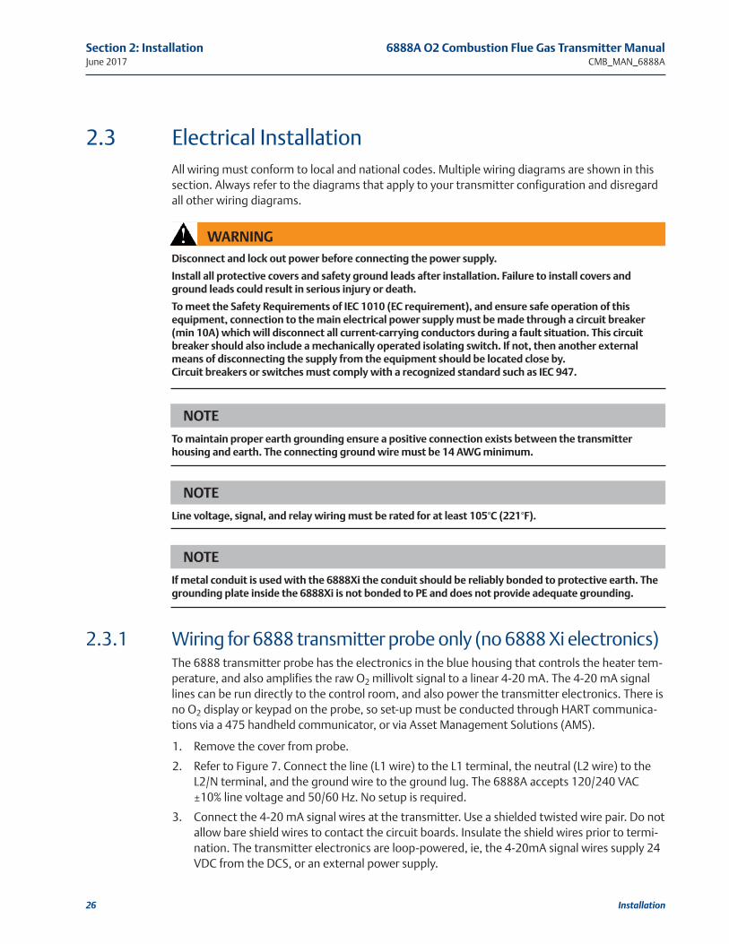
2.3 Electrical InstallationAll wiring must conform to local and national codes. Multiple wiring diagrams are shown in thissection. Always refer to the diagrams that apply to your transmitter configuration and disregardall other wiring diagrams.
NOTE
Line voltage, signal, and relay wiring must be rated for at least 105°C (221°F).
NOTE
If metal conduit is used with the 6888Xi the conduit should be reliably bonded to protective earth. Thegrounding plate inside the 6888Xi is not bonded to PE and does not provide adequate grounding.
2.3.1 Wiring for 6888 transmitter probe only (no 6888 Xi electronics)The 6888 transmitter probe has the electronics in the blue housing that controls the heater tem-perature, and also amplifies the raw O2 millivolt signal to a linear 4-20 mA. The 4-20 mA signallines can be run directly to the control room, and also power the transmitter electronics. There isno O2 display or keypad on the probe, so set-up must be conducted through HART communica-tions via a 475 handheld communicator, or via Asset Management Solutions (AMS).
1. Remove the cover from probe.
2. Refer to Figure 7. Connect the line (L1 wire) to the L1 terminal, the neutral (L2 wire) to theL2/N terminal, and the ground wire to the ground lug. The 6888A accepts 120/240 VAC±10% line voltage and 50/60 Hz. No setup is required.
3. Connect the 4-20 mA signal wires at the transmitter. Use a shielded twisted wire pair. Do notallow bare shield wires to contact the circuit boards. Insulate the shield wires prior to termi-nation. The transmitter electronics are loop-powered, ie, the 4-20mA signal wires supply 24VDC from the DCS, or an external power supply.

Installation 27
6888A O2 Combustion Flue Gas Transmitter Manual Section 2: InstallationCMB_MAN_6888A June 2017
FIGURE 2-12
6888A Standard Probe Housing
4. Terminate the shield only at the transmitter electronics housing unless using a 6888Xi.When using the 6888Xi Advanced Electronics, terminate the shield at both ends.
5. Reinstall cover on transmitter.
6. Follow the remaining electrical installation instructions only if the 6888Xi is
included with your system configuration.
2.3.2 Standard Housing Transmitter Probe plus 6888Xi ElectronicsThe 6888Xi electronics serve as an operator interface unit, with a back-lit display and keypad. It iscapable of two channels, serving two 6888 probes.
1. Remove cover screws from the front cover of the 6888Xi. Swing down the front cover of theinterface box.
2. Pull out the I/O board on the right-hand side of the card rack inside the 6888Xi. If your sys-tem is configured to operate two transmitter probes there are two I/O interface boards.
3. See Figure 8. Connect the 4-20 mA signal wires at J4 of the I/O board. Attach the supplied fer-rite clamp over the 4-20 mA OUT wires that extend past the shield.
NOTE
The 4-20 mA signal represents the O2 value and also powers the probe-mounted electronics.Superimposed on the 4-20 mA signal is HART information accessible through a 475 Field Communicatoror AMS software.

28 Installation
Section 2: Installation 6888A O2 Combustion Flue Gas Transmitter ManualJune 2017 CMB_MAN_6888A
4. Terminate the shield of the 4-20 mA signal wires at the designated ground terminal of the6888Xi. Do not allow bare shield wires to contact the circuit boards. Insulate the shield wiresprior to termination.
5. Connect the signal wires from the SPS or IMPS (if used) to the applicable terminals of J3.Refer to the SPS or IMPS instruction manual for wiring details.
6. Reinstall the I/O board in the card rack of the 6888Xi.
7. If your system is configured for two channel operation, repeat steps 2 through 7 to connectthe other probe’s signal wires.
8. Remove the probe’s connector from the power supply board located on the left-hand side ofthe card rack inside the 6888Xi.
9. Connect the line, or L1 wire to the L1 terminal and the neutral, or L2 wire, to the N terminal.
10. Reinstall the power supply connector in the power supply board.
2.3.3 Standard Housing Transmitter Probe plus 6888Xi ElectronicsThe 6888Xi electronics serve as an operator interface unit, with a back-lit display and keypad. It iscapable of two channels, serving two 6888 probes.
1. Remove cover screws from the front cover of the 6888Xi. Swing down the front cover of theinterface box.
2. Pull out the I/O board on the right-hand side of the card rack inside the 6888Xi. If your sys-tem is configured to operate two transmitter probes there are two I/O interface boards.
3. See Figure 8. Connect the 4-20 mA signal wires at J4 of the I/O board. Attach the suppliedferrite clamp over the 4-20 mA OUT wires that extend past the shield.
4. Terminate the shield of the 4-20 mA signal wires at the designated ground terminal of the6888Xi. Do not allow bare shield wires to contact the circuit boards. Insulate the shield wiresprior to termination.
5. Connect the signal wires from the SPS or IMPS (if used) to the applicable terminals of J3.Refer to the SPS or IMPS instruction manual for wiring details.
6. Reinstall the I/O board in the card rack of the 6888Xi.
7. If your system is configured for two channel operation, repeat steps 2 through 7 to connectthe other probe’s signal wires.
8. Remove the probe’s connector from the power supply board located on the left-hand side ofthe card rack inside the 6888Xi.
9. Connect the line, or L1 wire to the L1 terminal and the neutral, or L2 wire, to the N terminal.
10. Reinstall the power supply connector in the power supply board.
NOTE
Installation of the ferrite clamp over the 4-20 mA OUT wires is required for compliance with theEuropean EMC Directive.
NOTE
Installation of the ferrite clamp over the 4-20 mA OUT wires is required for compliance with theEuropean EMC Directive.

Installation 29
6888A O2 Combustion Flue Gas Transmitter Manual Section 2: InstallationCMB_MAN_6888A June 2017
Figure 2-13. Wiring Diagrams – Single/Dual Channel Wiring Diagram

30 Installation
Section 2: Installation 6888A O2 Combustion Flue Gas Transmitter ManualJune 2017 CMB_MAN_6888A
Figure 2-14. Wiring Diagrams – Single/Dual Channel Wiring Diagram

Installation 31
6888A O2 Combustion Flue Gas Transmitter Manual Section 2: InstallationCMB_MAN_6888A June 2017
2.3.4 Transmitter probe with single-channel Xi and Flame Safety Interlock
A flame safety interlock by Emerson is available for heater power disconnect whenever there is aloss of the process flame or a heater runaway condition (heater over-temperature) in the O2Probe. This input is internally powered by the 6888Xi and is actuated via a dry contact outputfrom the user’s flame scanner. A closed contact indicates a flame is present. An open contactindicates a loss of flame.
1. Refer to Figures 13 and 14. Connect the signal wires from the burner management systemflame status output to the flame status input terminals of J2. The flame status sensing deviceis supplied by the customer. Refer to the applicable OEM documents for signal wiring details.
2. Remove the J1 and J2 connectors from the AC relay board.
3. Connect the AC line input to the J1 connector.
4. Connect the AC power to the 6888A probe to the J2 connector.
5. Reinstall connector J1 and J2 to the AC relay board.
2.3.5 Transmitter Probe with Integral Autocal and HART communications
This probe contains gas-switching solenoids so that the 6888Xi electronics can control the intro-duction of calibration gases. Calibrations can be initiated via a calibration recommended diag-nostic, time since last calibration, manually via external dry contact, HART communications, orfrom the 6888Xi local operator interface keypad. The integral autocal feature can only be imple-mented when the probe is used with a 6888Xi.
1. Remove the two covers from the transmitter.
2. Refer to Figures 15 and 16. Connect the line (L1 wire) to the L1 terminal, the neutral (L2wire) to the L2/N terminal, and the ground wire to the ground lug. The 6888A accepts120/240 VAC ± 10% line voltage and 50/60 Hz. No setup is required.
3. Connect the 4-20mA signal wires from the 6888XI to the connections in the side chamber ofthe transmitter. DO NOT connect the signal wires to the terminals in the main chamber werethe AC input wires are connected. Use a shielded twisted wire pair. Do not allow bare shieldwires to contact the circuit boards. Insulate the shield wires prior to termination. The 24VDC loop power is sourced from the 6888XI.
4. Terminate the shield at both the probe and the 6888Xi Advanced Electronics.
5. Reinstall both covers on transmitter.
6. Follow the remaining electrical installation instructions for the 6888Xi included with yoursystem configuration.
NOTE
The 4-20 mA signal represents the O2 value and also powers the probe-mounted electronics. Superimposedon the 4-20 mA signal is HART information accessible through a Field Communicator or AMS software.

32 Installation
Section 2: Installation 6888A O2 Combustion Flue Gas Transmitter ManualJune 2017 CMB_MAN_6888A
Figure 2-15. Wiring Diagrams – Single Channel with Flame Safety, Wiring Diagram

Installation 33
6888A O2 Combustion Flue Gas Transmitter Manual Section 2: InstallationCMB_MAN_6888A June 2017
Figure 2-16. Wiring Diagrams – Single Channel with Flame Safety, Wiring Diagram

34 Installation
Section 2: Installation 6888A O2 Combustion Flue Gas Transmitter ManualJune 2017 CMB_MAN_6888A
2.3.6 Transmitter Probe with Integral Autocal and FOUNDATION Fieldbus communications
This probe contains gas-switching solenoids so that the 6888Xi electronics can control the intro-duction of calibration gases. Calibrations can be initiated via a calibration recommended diag-nostic, time since last calibration, manually via external dry contact, HART communications, orfrom the 6888Xi local operator interface keypad. The integral autocal feature can only be imple-mented when the probe is used with a 6888Xi.
1. Remove the two covers from the transmitter.
2. Connect the line (L1 wire) to the L1 terminal, the neutral (L2 wire) to the L2/N terminal, andthe ground wire to the ground lug. The 6888A accepts 120/240 VAC ± 10% line voltage and50/60 Hz. No setup is required.
3. Connect the FOUNDATION Fieldbus wires from the 6888 side housing to the FF segment.Note that the 6888 probe is not rated as intrinsically safe, and will render any IS or FISCOsegment it is wired to as non-IS. Use a shielded twisted wire pair. Do not allow bare shieldwires to contact the circuit boards.
4. Terminate the shield at both the probe and the 6888Xi Advanced Electronics.
5. Reinstall both covers on transmitter.
6. Follow the remaining electrical installation instructions for the 6888Xi included with yoursystem configuration.
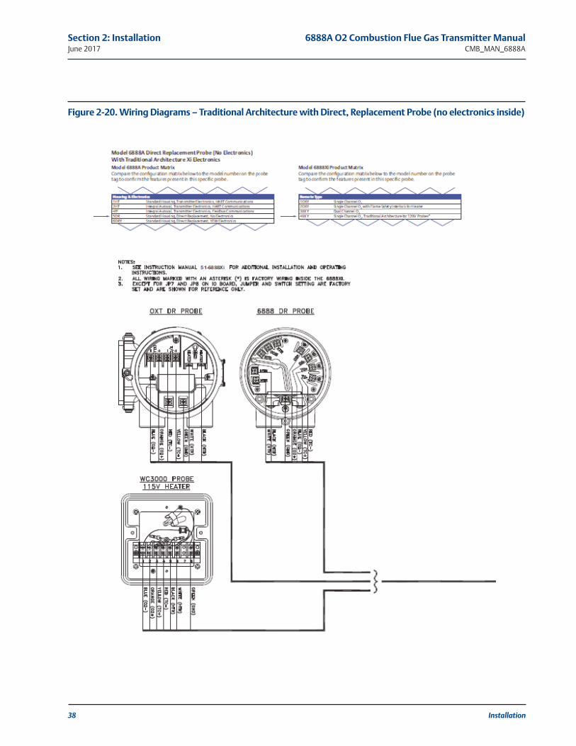
2.3.7 Traditional Architecture System with Direct Replacement Probe (no electronics inside)
Here there are no electronics inside the probe head, so the raw sensor signals for the heater ther-mocouple and zirconium oxide O2 sensor are sent to a remote 6888Xi Electronics. The 6888Xielectronics will also directly apply power to the probe heater in order to maintain the correctsensor temperature. This arrangement calls for a 7- conductor cable to carry this power and thesensor signals. Maximum length for this cable is 200 feet.
1. Remove cover from probe.
2. Feed all DR probe wiring through the conduit port of probe.
3. Refer to Figures 20 and 21. Connect DR probe heater power leads to DR probe connec-tor.
4. Connect O2 signal and thermocouple wires to DR probe connector.
NOTE
The FOUNDATION Fieldbus signal represents the O2 value and also powers the probe-mounted electronics.

Installation 35
6888A O2 Combustion Flue Gas Transmitter Manual Section 2: InstallationCMB_MAN_6888A June 2017
Figure 2-17. Wiring Diagrams – Integral Autocal and FOUNDATION Fieldbus, Communications without
Optional Xi

36 Installation
Section 2: Installation 6888A O2 Combustion Flue Gas Transmitter ManualJune 2017 CMB_MAN_6888A
Figure 2-18. Wiring Diagrams –Integral Autocal and FOUNDATION Fieldbus, Communications and Optional Xi

Installation 37
6888A O2 Combustion Flue Gas Transmitter Manual Section 2: InstallationCMB_MAN_6888A June 2017
Figure 2-19. Wiring Diagrams – Integral Autocal and FOUNDATION Fieldbus, Communications and Optional Xi
38 Installation
Section 2: Installation 6888A O2 Combustion Flue Gas Transmitter ManualJune 2017 CMB_MAN_6888A
Figure 2-20. Wiring Diagrams – Traditional Architecture with Direct, Replacement Probe (no electronics inside)

Installation 39
6888A O2 Combustion Flue Gas Transmitter Manual Section 2: InstallationCMB_MAN_6888A June 2017
Figure 2-21. Wiring Diagrams – Traditional Architecture with Direct, Replacement Probe (no electronics inside)

40 Installation
Section 2: Installation 6888A O2 Combustion Flue Gas Transmitter ManualJune 2017 CMB_MAN_6888A
Figure 2-22. Wiring Diagrams – Existing Yokogawa Electronics (must have YEW 6888 probe with cold junc-tion device in the probe terminations.)

Installation 41
6888A O2 Combustion Flue Gas Transmitter Manual Section 2: InstallationCMB_MAN_6888A June 2017
2.3.8 Traditional Architecture Cable ConnectionsA traditional architecture configuration is used to provide for remote location of the transmitterelectronics. All electronics are housed inside the 6888Xi. A multi-conductor power/signal cableconnects between the probe and the 6888Xi. Use the following procedure to connect the tradi-tional architecture probe to the 6888Xi.
1. Run the 7-conductor cable between the traditional architecture probe and the installationsite for 6888Xi. Use new cable conduit or trough as needed.
2. Install the cable and lead wires to the probe per manufacturer’s instructions.
3. Install the cable at the probe housing and at the 6888Xi enclosure according to the followingprocedure:
a. Unscrew locking nut from gland assembly, Figure 8, and slide locking nut back alongcable.
b. Pull the gland body away from the plastic insert. Use care not to damage the cableshield braid.
c. Insert the cable wires into the proper entry port in either the probe housing or the6888Xi enclosure.
d. At the probe housing, apply Teflon tape or similar sealing compound to the tapered pipethreads. Thread the gland body into the probe housing until properly seated.
e. At the 6888Xi enclosure, insert the gland body into the left front cable port from theinside of the enclosure. Use the rubber O-ring provided to seal the cable port.
f. Ensure the cable shield braid is evenly formed over the gray insert. When properlyformed, the braid should be evenly spaced around the circumference of the insert andnot extend beyond the narrow diameter portion.
g. Carefully press the gray insert into the gland body. The grooves on the insert shouldalign with similar grooves inside the gland body. Press the insert in until it bottoms outin the gland body.
h. Slide the locking nut up and thread it onto the gland body. Tighten the locking nut sothe rubber grommet inside the plastic insert compresses against the cable wall to pro-vide an environmental seal.
4. At the 6888Xi, connect the cable leads to the connectors on the transmitter I/O board asindicated in Figures 20 1nd 21.
NOTEThe Traditional Architecture cable is provided at the specified length and is ready for installation. Thecable glands must be properly terminated to maintain EMC/EMI noise protection.
NOTEFor electrical installation instructions for connecting to a Xi or Oxymitter electronics, see the QuickStart manual.

42 Installation
Section 2: Installation 6888A O2 Combustion Flue Gas Transmitter ManualJune 2017 CMB_MAN_6888A
2.4 Pneumatic Installation2.4.1 Reference Air Package
After the 6888A is installed, connect the reference air set to the 6888A unit. Refer to theschematic diagram in Figure 2-23 and the mounting dimensions in Figure 2-24 for a locallyassembled reference air supply.
Instrument Air (Reference Air): 5 psi (34 kPa) minimum, 8 psi (54 kPa) maximum at 2.0 scfh (1.0 l/min) maximum; less than 40 parts per million total hydrocarbons. Regulator outletpressure should be set at 5 psi (34 kPa). Reference air can be supplied by the reference air setor the optional SPS 4001B or IMPS 4000.
FIGURE 2-23. Plant Air Schematic Diagram
Reference air components are included in the optional Manual Calibration Panel (Figure 2-24),the SPS 4001 Single Probe Autocalibration Sequencer, and the IMPS 4000 Intelligent MultiprobeTest Gas Sequencer.
See the SPS 4001B Single Probe Autocalibration Sequencer Instruction Manual or the IMPS 4000Intelligent Multiprobe Test Gas Sequencer Instruction Manual for wiring and pneumatic connections.
NOTEThe optional SPS 4001B or IMPS 4000 Sequencer can only be used when the 6888Xi AdvancedElectronics option is selected. The 6888Xi must be properly configured for autocalibration. See Section3: Configuration.

Installation 43
6888A O2 Combustion Flue Gas Transmitter Manual Section 2: InstallationCMB_MAN_6888A June 2017
FIGURE 2-24. Manual Calibration Panel

44 Installation
Section 2: Installation 6888A O2 Combustion Flue Gas Transmitter ManualJune 2017 CMB_MAN_6888A
FIGURE 2-25. 6888A Calibration Gas Connections
2.4.2 Calibration Gas Two calibration gas concentrations are used with the 6888A, Low Gas - 0.4% O2, balance N2, andHigh Gas - 8% O2, balance N2. An optional Manual Calibration Panel is shown in Figure 2-13. SeeFigure 2-14 for the 6888A probe calibration gas connection ports.
Calibration Gas: 15 psig (103 kPa gage) maximum, 5 SCFH (2,5 L/min). Establish the calibrationgas flow only with a clean diffuser.
CAUTION
Do not use 100% nitrogen as a low gas (zero gas). It is suggested that gas for the low (zero) be between0.4% and 2.0% O2. Do not use gases with hydrocarbon concentrations of more than 40 parts per million.Failure to use proper gases will result in erroneous readings.
CAUTIONIf the ducts will be washed down during outage, MAKE SURE to power down the 6888A units andremove them from the wash areas.
NOTEUpon completing installation, make sure that the 6888A is turned on and operating prior to firing upthe combustion process. Damage can result from having a cold 6888A unit exposed to the processgases. During outages, if possible, leave all 6888A units running to prevent condensation andpremature aging from thermal cycling.
FIGURE 2-26. Traditional Architecture Cable Gland Assembly

Installation 45
6888A O2 Combustion Flue Gas Transmitter Manual Section 2: InstallationCMB_MAN_6888A June 2017
2.5 Pneumatic Installation
2.5.1 Reference Air PackageAfter the 6888 is installed, connect the reference air set to the 6888 unit. Refer to the schematicdiagram and the mounting dimensions in Figure 16 for a locally assembled reference air supply.
Instrument Air (Reference Air): 5 psi (34 kPa) minimum, 8 psi (54 kPa) maximum at 2.0 scfh (1.0l/min) maximum; less than 40 parts per million total hydrocarbons. Regulator outlet pressureshould be set at 5 psi (34 kPa). Reference air is recommended, or the reference air fittings can beleft open to atomsphere. SPS 4001B or IMPS 4000 autocal boxes contain reference air sets.
Figure 27. Plant Air Schematic Diagram, Standard Housing
Figure 28. Plant Air Schematic Diagram, Accessory Housing

46 Installation
Section 2: Installation 6888A O2 Combustion Flue Gas Transmitter ManualJune 2017 CMB_MAN_6888A
This page left intentionally blank.

3.1 Powering Up 6888 Transmitter without 6888Xi1 Apply AC line power to the Transmitter.
2. Apply 24 VDC loop power to the Transmitter.
3. Using either the DCS control or a Field Communicator, verify communications to the Transmitter.
4. The transmitter probe will take approximately 45 minutes to warm up to the 736°C heatersetpoint. The 4-20 mA signal will remain at a default value of 3.5 mA and the O2 reading willremain at 0% through this warm-up period. After warm up, the probe will begin readingoxygen and the 4-20 mA output will be based on the default range of 0-10% O2.
5. If there is an error condition at startup, an alarm message will be displayed. Refer to fullinstruction manual for troubleshooting alarms.
3.2 Powering Up 6888 Transmitter With Single/Dual Channel or Single Channel & Flame Safety Interlock 6888Xi
1. Apply AC line power to the Transmitter.
2. Apply AC line power to 6888Xi. Run the Quick Start Wizard as described below. At the “AutoCal Device” screen select the calibration method based on the 6888 Transmitter as follows:
a. Standard Probe Housing Configuration – Select None, SPS or IMPS as appropriate. Donot select Integral or calibration will not be possible.
b. Integral Autocal Probe housing – Select Integral only. If Integral is not selected, calibra-tion will not be possible.
3. Verify communications between the Transmitter and the 6888Xi. The 6888Xi display is pre-configured to display O2 & cell temperature for single channel configurations and both O2
readings for dual channel configurations.
4. The transmitter probes will take approximately 45 minutes to warm up to the 736°C heatersetpoint. The 4-20 mA signal will remain at a default value of 3.5 mA and the O2 reading willremain at 0% through this warm-up period. After warm up, the probe will begin readingoxygen and the 4-20 mA output will be based on the default range of 0-10% O2.
Configuration, Startup and Operation 47
6888A O2 Combustion Flue Gas Transmitter Manual Section 3: Configuration, Startup and Operation CMB_MAN_6888A June 2017
Section 3: Configuration, Startupand Operation
WARNING
Install all protective equipment covers and safety ground leads before equipment startup. Failure toinstall covers and ground leads could result in serious injury or death.
CAUTION
If external loop power is used, the power supply must be a safety extra low voltage (SELV) type.

48 Configuration, Startup and Operation
Section 3: Configuration, Startup and Operation 6888A O2 Combustion Flue Gas Transmitter ManualJune 2017 CMB_MAN_6888A
5. If there is an error condition at startup, an alarm message will be displayed on the 6888Xi.Refer to full instruction manual for troubleshooting alarms. 6888 Direct Replacement Probe(no electronics).
3.3 6888 Direct Replacement Probe (no electronics inside) with Traditional Architecture 6888Xi
1. Apply AC line power to 6888XI. Run the Quick Start Wizard as described below. At the “AutoCal Device” screen select None, SPS or IMPS as appropriate. Do not select Integral or calibra-tion will not be possible.
2. The direct replacement probe will take approximately 45 minutes to warm up to the 736°Cheater setpoint. The 4-20 mA signal will remain at a default value of 3.5 mA and the O2reading will remain at 0% through this warm-up period. After warm up, the probe will beginreading oxygen and the 4-20 mA output will be based on the default range of 0-10% O2.
3. If there is an error condition at startup, an alarm message will be displayed on the 6888Xi.Refer to full instruction manual for troubleshooting alarms.
3.4 6888Xi Quick Start WizardWhen the 6888Xi is first powered, a short wizard program will guide the user through the basicsetup. Once configured, the 6888XI will retain the setup and the wizard will not repeat.
1. Apply power to 6888XI. Once boot-up is complete, the “Quick Start” wizard screen willappear. With a dual channel 6888XI, the wizard will run for both channels in succession.Press the <Enter> key to continue.
2. At the “Sensor Type” screen, use the Up/Down keys to select “O2”. Do not select “CO” asthis option is reserved for future use. Press the <Enter> key to continue.
3. At the “Device Type” screen, use the Up/Down keys to select HART or FF (FOUNDATIONFieldbus), whichever applies.
4. At the “Auto Cal Device” screen, use the Up/Down keys to select the calibration method tobe used. The methods are defined as follows:
None – Manual calibration with the standard probe housing configuration
SPS – Automatic calibration with the standard probe housing configuration using the SPS4001B
IMPS– Automatic calibration with the standard probe housing configuration using the IMPS
Integral – Automatic calibration with the integral autocal probe housing configuration
Press the <Enter> key to continue.
5. When prompted if “Setup Correct?”, use the Up/Down keys to select “Yes”. If “No” is select-ed, the wizard will restart. Press the <Enter> key to continue.
6. The 6888Xi will display several screens while saving the configuration, reset itself then returnto the main screen.
NOTEIf SPS, IMPS or Integral is selected, the user must still configure automatic calibration as “On”. Otherparameter such as test gas values and gas times should be verified as well. Refer to 6888Xi fullinstruction manual for calibration setup details.

Configuration, Startup and Operation 49
6888A O2 Combustion Flue Gas Transmitter Manual Section 3: Configuration, Startup and Operation CMB_MAN_6888A June 2017
3.5 Re-initiating 6888Xi WizardTo re-initiate the wizard setup, the IO board must be reset to factory default conditions.
1. Apply power to 6888XI.
2. When the main screen appears, press the <Menu> key several times until the “System” menuappears. Use the Up/Down keys to select “Configure IOB”. Press the <Enter> key to continue.
3. When the configure IOB screen appears, use the Up/Down keys to select “I/O Board 1”.With a dual channel 6888XI, either or both I/O boards may be reset and reconfigured. Pressthe <Enter> key to continue.
4. When the I/O board 1 menu appears, use the Up/Down keys to select “Reset I/O Board”.Press the <Enter> key to continue.
5. When the reset menu appears, use the Up/Down keys to select “Factory Defaults”. Press the<Enter> key to continue.
6. When prompted, use the Up/Down keys to select “Yes”. Press the <Enter> key to continue.
7. The 6888Xi will display several screens while saving the configuration, reset itself then dis-play the wizard screen.
3.6 CalibrationThe 6888 O2 analyzer system can be calibrated in the installed condition without removing theinstrument from the process duct and also while the combustion process is on-line. A stainlesssteel tube runs the length of the probe, and delivers the calibration gasses into the cell area.Factory calibration will usually be satisfactory for initial start-up and operation, but most accu-rate measurement is gained by executing a calibration under normal operating conditions.
Recommended calibration gases are 0.4% O2 and 8% O2, with the balance of nitrogen in the gasbottles, but other values can be used as long as the electronics are configured identically.Instrument air or pure nitrogen are not recommended as calibration gas values. A two-stagepressure regulator should be used to establish a pressure of 20 PSI, from the bottles, and theflowmeter should be set to 5 SCFH flow rate.
3.6.1 Manual/Semi-automatic CalibrationThe 6888 probe with the standard housing can be calibrated in a semi-automatic fashion, with atechnician following prompts via the display of the Xi electronics or via HART communicationsto a 475 handheld communicator or AMS console. The technician will need to manually switchthe gases based upon these prompts. Recommended calibration gases are 0.4% O2 and 8% O2,balance nitrogen. A two-stage pressure regulator should always be used, set to 20 PSI. The cali-bration gas flowmeter should be set for 5 SCFH, with the cal gas fitting removed from the probe.A diffuser/filter that is plugged over time may cause the flowmeter to deliver less flow to thesensing cell, but the flow rate should never be readjusted until a new diffuser is installed.Readjusting the flowmeter back up to the 5 SCFH level could pressurize the cell during calibra-tion, and cause the O2 reading to shift downwards.
The electronics will determine if the calibration was successful, and calculate new calibration val-ues. New calibration values are not automatically loaded into the electronics after a successfulcalibration, however. The technician has the opportunity of accepting the new values or not. (Asignificant calibration change may cause a bump in the O2 readings at the DCS console, causingthe operator concern). Record the calibration data on the log provided (cell slope, constant, and

50 Configuration, Startup and Operation
Section 3: Configuration, Startup and Operation 6888A O2 Combustion Flue Gas Transmitter ManualJune 2017 CMB_MAN_6888A
impedance, as well as the speed of response data). If the electronics ps used, it will store calibra-tion data for the past 10 successful calibrations.
Make sure that the calibration gas port is capped tightly between calibrations. A loose or missingcap can permit fresh air to bias the O2 readings high in processes that run at negative pressure.
3.6.2 Fully Automatic CalibrationFully automatic calibration requires the Xi electronics to manage the actuation of solenoids tointroduce gases into the probe.
6888 Probes with Standard Electronics HousingIn addition to the Xi, this arrangement requires a separate Single Probe Sequencer (SPS), whichis a solenoid box for switching calibration gases, or a larger Intelligent Multiprobe Sequencer(IMPS), which can handle the autocal for up to 4 probes in one box.
The automatic calibrations can be initiated in several ways:
• Via a “calibration recommended” diagnostic that is periodically checking cell impedance
• Via pushbutton on the Xi electronics
• Via HART communications from a 475 handheld communicator, or AMS
• Via an external contact closure
• Via time since the last successful calibration
If the O2 measurement is being used for automatic control, always place the O2 control loop intomanual prior to calibrating. Always inform the operator prior to calibrating. The Xi electronicsprovides an “in cal” contact closure for this purpose. An “intiate cal” contact is also provided.
The Xi electronics will sequence the calibration gases in turn into the sensing cell. A 300 secondflow time is the factory default for both gases, and also for the purge cycle, which lets the probesignal come back to the normal flue gas readings. The 4-20 Ma signal representing O2 can beheld during the calibration cycle, or permitted to vary with the bottled gases, in which case arecord of the calibration can be trended at the DCS.
Calibration setup is found under the detailed setup menu.
6888 Probe with Integral Autocal HousingThis probe contains the autocal solenoids within the blue electronics housing, eliminating theneed and cost for an SPS or IMPS solenoid enclosure. Both calibration gases are permanentlypiped into two ports on the probe. It’s important to confirm that there are no piping leaks, orthe calibration bottles will leak down prematurely.
Note 1: The calibration sequence from the Xi electronics will be identical to that for the manu-al/semiautomatic calibration , but note that with the integral autocal version of this probe it isnot possible to conduct a manual calibration. The factory offers a probe rebuild capability if sole-noid or other failures occur.
Note 2: Calibration gas bottle will be piped and under pressure at all times, so be sure to leak-check all fittings, tubing and connections. Always use dual-stage pressure regulators.
3.6.3 Other Features Associated with Calibration1. “Cal Check” capability. A user can choose to look at new calibration values prior to having
them load in and become active. If this feature is selected, a “calibration changed” alarmwill come up after the calibration is complete. By pushing the “Diagnostics” button on theXi, an “Accept Cal” step can be required so that the technician and operator can decide if

Configuration, Startup and Operation 51
6888A O2 Combustion Flue Gas Transmitter Manual Section 3: Configuration, Startup and Operation CMB_MAN_6888A June 2017
they are ready to accept a potentially large change in calibration values.
2. Plugged Diffuser Diagnostic- this feature measures the return-to-process rate after calibra-tion gases are removed, and will alarm when this time exceeds 75% of the purge time con-figured. A “purge time too short” alarm is an indication that the diagnostic could not workbecause of a short purge time, and is another indication that the diffuser is plugged. Purgetime should be increased in this case.
Another feature that comes with the Plugged Diffuser Diagnostic is Auto Gas Switching.This feature switches cal gases, and also ends the purge sequence when the readings settleout, vs. waiting for a configured flow time. This saves time and gas.
3. Tolerance Check that will alarm if the cell MV signal is significantly different than the expect-ed signal of the bottles noted in the setup. This will indicate if the wrong bottles are beingused, or if a bottle runs out in the middle of a calibration.
Calibration Setup is under the Detailed Setup menu.
Calibration set-up can be found in the Xi menu :
Factory default menu see figure 18.
Figure 3-1. Calibration Defaults

52 Configuration, Startup and Operation
Section 3: Configuration, Startup and Operation 6888A O2 Combustion Flue Gas Transmitter ManualJune 2017 CMB_MAN_6888A
Figure 3-2. HART Menu Trees – 6888 Xi
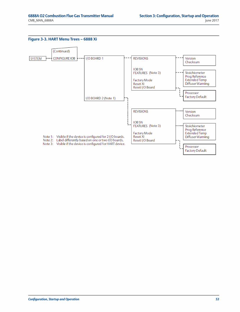
Configuration, Startup and Operation 53
6888A O2 Combustion Flue Gas Transmitter Manual Section 3: Configuration, Startup and Operation CMB_MAN_6888A June 2017
Figure 3-3. HART Menu Trees – 6888 Xi

54 Configuration, Startup and Operation
Section 3: Configuration, Startup and Operation 6888A O2 Combustion Flue Gas Transmitter ManualJune 2017 CMB_MAN_6888A
Figure 3-4. HART Menu Trees – 6888 Xi

Configuration, Startup and Operation 55
6888A O2 Combustion Flue Gas Transmitter Manual Section 3: Configuration, Startup and Operation CMB_MAN_6888A June 2017
Figure 3-5. HART Menu Trees – 6888 Xi

56 Configuration, Startup and Operation
Section 3: Configuration, Startup and Operation 6888A O2 Combustion Flue Gas Transmitter ManualJune 2017 CMB_MAN_6888A
Figure 3-6. HART Menu Trees – 6888 Xi

Configuration, Startup and Operation 57
6888A O2 Combustion Flue Gas Transmitter Manual Section 3: Configuration, Startup and Operation CMB_MAN_6888A June 2017
Figure 3-7. HART Menu Trees – 6888 Xi

58 Configuration, Startup and Operation
Section 3: Configuration, Startup and Operation 6888A O2 Combustion Flue Gas Transmitter ManualJune 2017 CMB_MAN_6888A
Figure 3-8. HART Menu Trees – 375/475 Field Communicator

Configuration, Startup and Operation 59
6888A O2 Combustion Flue Gas Transmitter Manual Section 3: Configuration, Startup and Operation CMB_MAN_6888A June 2017
Figure 3-9. HART Menu Trees – 375/475 Field Communicator

60 Configuration, Startup and Operation
Section 3: Configuration, Startup and Operation 6888A O2 Combustion Flue Gas Transmitter ManualJune 2017 CMB_MAN_6888A
Figure 3-10. HART Menu Trees – 375/475 Field Communicator

Configuration, Startup and Operation 61
6888A O2 Combustion Flue Gas Transmitter Manual Section 3: Configuration, Startup and Operation CMB_MAN_6888A June 2017
Figure 3-11. HART Menu Trees – 375/475 Field Communicator

62 Configuration, Startup and Operation
Section 3: Configuration, Startup and Operation 6888A O2 Combustion Flue Gas Transmitter ManualJune 2017 CMB_MAN_6888A
Figure 3-12. FOUNDATION Fieldbus Menu Trees – 6888 Xi

Configuration, Startup and Operation 63
6888A O2 Combustion Flue Gas Transmitter Manual Section 3: Configuration, Startup and Operation CMB_MAN_6888A June 2017
Figure 3-13. FOUNDATION Fieldbus Menu Trees – 6888 Xi

64 Configuration, Startup and Operation
Section 3: Configuration, Startup and Operation 6888A O2 Combustion Flue Gas Transmitter ManualJune 2017 CMB_MAN_6888A
Figure 3-14. FOUNDATION Fieldbus Menu Trees – 6888 Xi

Configuration, Startup and Operation 65
6888A O2 Combustion Flue Gas Transmitter Manual Section 3: Configuration, Startup and Operation CMB_MAN_6888A June 2017
Figure 3-15. FOUNDATION Fieldbus Menu Trees – 6888 Xi

66 Configuration, Startup and Operation
Section 3: Configuration, Startup and Operation 6888A O2 Combustion Flue Gas Transmitter ManualJune 2017 CMB_MAN_6888A
Figure 3-16. FOUNDATION Fieldbus Menu Trees – 6888 Xi

Configuration, Startup and Operation 67
6888A O2 Combustion Flue Gas Transmitter Manual Section 3: Configuration, Startup and Operation CMB_MAN_6888A June 2017
Figure 3-17. FOUNDATION Fieldbus Menu Trees – 6888 Xi

68 Configuration, Startup and Operation
Section 3: Configuration, Startup and Operation 6888A O2 Combustion Flue Gas Transmitter ManualJune 2017 CMB_MAN_6888A
Figure 3-18. FOUNDATION Fieldbus Menu Trees – 375/475 Field Communicator
Note1: N/ANote 2: Visible if the Programmable Reference software feature is enabled.Note 3: Visible if the Extended Temperature software is enabled.Note 4: Visible if the Diffuser Warning software feature is enabled.
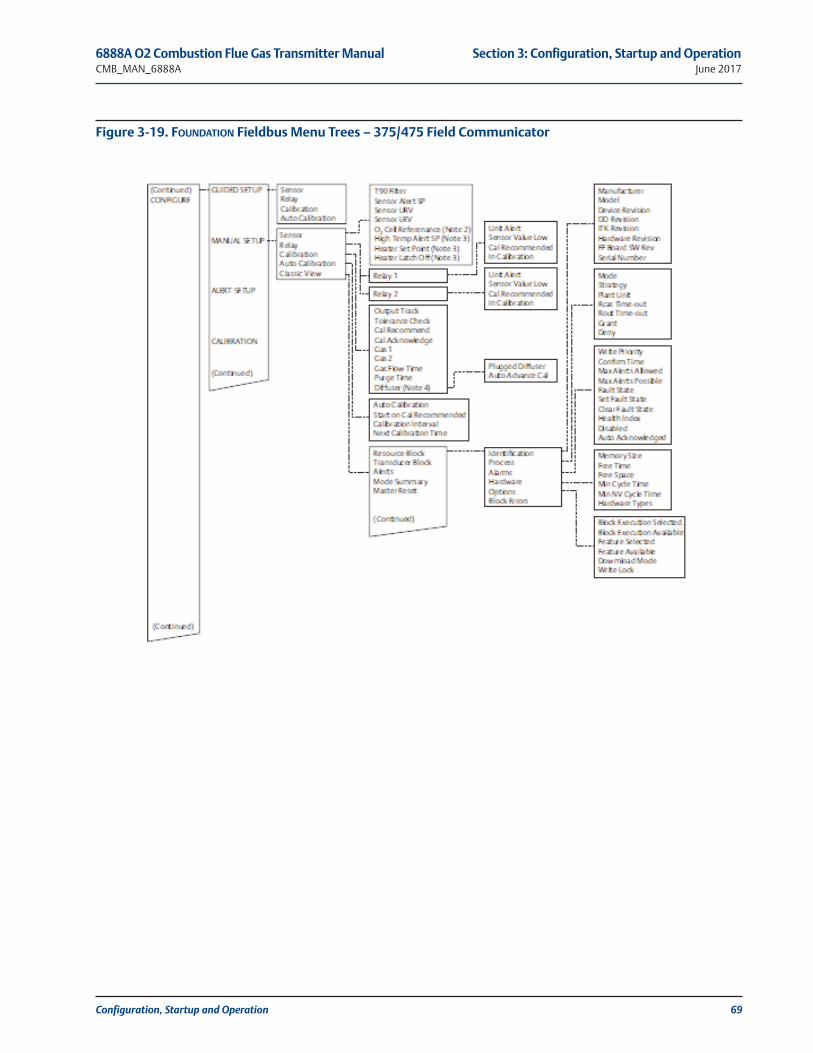
Configuration, Startup and Operation 69
6888A O2 Combustion Flue Gas Transmitter Manual Section 3: Configuration, Startup and Operation CMB_MAN_6888A June 2017
Figure 3-19. FOUNDATION Fieldbus Menu Trees – 375/475 Field Communicator

70 Configuration, Startup and Operation
Section 3: Configuration, Startup and Operation 6888A O2 Combustion Flue Gas Transmitter ManualJune 2017 CMB_MAN_6888A
Figure 3-20. FOUNDATION Fieldbus Menu Trees – 375/475 Field Communicator

Configuration, Startup and Operation 71
6888A O2 Combustion Flue Gas Transmitter Manual Section 3: Configuration, Startup and Operation CMB_MAN_6888A June 2017
Figure 3-21. FOUNDATION Fieldbus Menu Trees – 375/475 Field Communicator

72 Configuration, Startup and Operation
Section 3: Configuration, Startup and Operation 6888A O2 Combustion Flue Gas Transmitter ManualJune 2017 CMB_MAN_6888A
Figure 3-22. FOUNDATION Fieldbus Menu Trees – 375/475 Field Communicator

Configuration, Startup and Operation 73
6888A O2 Combustion Flue Gas Transmitter Manual Section 3: Configuration, Startup and Operation CMB_MAN_6888A June 2017
Figure 3-23. FOUNDATION Fieldbus Menu Trees – 375/475 Field Communicator

74 Configuration, Startup and Operation
Section 3: Configuration, Startup and Operation 6888A O2 Combustion Flue Gas Transmitter ManualJune 2017 CMB_MAN_6888A
Figure 3-24. FOUNDATION Fieldbus Menu Trees – 375/475 Field Communicator

Configuration, Startup and Operation 75
6888A O2 Combustion Flue Gas Transmitter Manual Section 3: Configuration, Startup and Operation CMB_MAN_6888A June 2017
Figure 3-25. FOUNDATION Fieldbus Menu Trees – 375/475 Field Communicator

76 Configuration, Startup and Operation
Section 3: Configuration, Startup and Operation 6888A O2 Combustion Flue Gas Transmitter ManualJune 2017 CMB_MAN_6888A
3.7 System Parameter DescriptionsAmong the parameters available through the 375/475 Communicator menus are a number of“System Parameters”. The system parameters define variables that configure a specific probe inthe transmitter system. System parameters are described in the following table.
Parameter Name Unit Description
O2 % Current oxygen concentration value (O2 %). The value should reflect the last good O2 value if it isin the “Lock” state during calibration.
O2 Temp degC Current O2 sensor temperature.
CJC Temp degC Current cold junction temperature.
O2 Cell mV Raw mV value for O2 sensor.
Cell Imp ohm Cell impedance/sensor resistance measured.
Heater V Heater voltage.
O2 AO mA Analog output value represents the O2 concentration measurement.
O2 Temp Max degC This is the highest O2 sensor temperature reached since last reset.
O2 Temp Max Time Days ago Time stamp of the highest O2 sensor temperature reached since last reset.
Temperature | CJC Max decC This is the highest temperature reached at the cold junction since last reset.
Temperature | CJCMax Time
Daysago
Time stamp of the highest temperature reached at the cold junction since last reset.
Voltage | Heater Max degC This is the highest heater voltage reached since last reset.
Voltage | Heater MaxTime
Daysago
Time stamp of the highest heater voltage reached since last reset.
Voltage | Cell Max degC This is the highest cell voltage reached since last reset.
Voltage | Cell MaxTime
Daysago
Time stamp of the highest cell voltage reached since last reset.
OP Mode -- Device operating mode:PO=Power up; WU=Warm Up (analog output is railed); NM=Normal operation;CA=Calibrating (analog output can be tracking or locked at last good value based on"AO Tracks" configuration); AL=Alarm detected (recoverable); SF=Alarm detected(non-recoverable)
Active Alarms -- Current Alarms (See Section 4, Troubleshooting)
Device -- Alarm state
Failed -- Alarm state: On/OffNV Memory Fail, Board Temp High, Factory Mode, Heater Ramp Rate
Maintenance 1 -- Alarm state: On/OffO2 Sensor Open, O2 T/C Open, O2 Temp Low, O2 Temp High, O2 T/C Shorted,O2 T/C Reversed, Heater Failure, Burner Flameout
Maintenance 2 -- Alarm state: On/OffXmtr Disconnect, Cal Recommended, Cal Failed, Cell Imp High, Probe Mismatch
Advisory -- Alarm state:Cal Changed, Htr Volt Low, Probe Changed, Low O2, Diffuser Warning
Duty Cycle -- O2 heater duty cycle. Value between 0 and 1.
O2 Temp SP degC PID temperature set point
Heater Ramp Rate degC/s Heater ramp rate calculated in degree C per second.
Operating Status Device configuration: On/OffFactory Mode, Flame Status (IO Board DIP Switch setting), Auto Cal Device, Relay 1 Device,Relay 2 Device, AO Device

Configuration, Startup and Operation 77
6888A O2 Combustion Flue Gas Transmitter Manual Section 3: Configuration, Startup and Operation CMB_MAN_6888A June 2017
Parameter Name Unit Description
Xmtr EE Val -- Transmitter board nonvolatile memory diagnostic.
Xmtr Restart -- Software restarts count for the Transmitter.
HART | Device Rev -- HART Device Revision number.
Transmitter | Version -- Software version number for the Transmitter.
Tag -- Device tag: Up to 8 characters long.
Serial Number -- Probe serial number.
Device ID -- Unique Device ID number. (HART)
PV -- Primary variable assignment: O2 (HART)
SV -- Secondary variable assignment: O2 Temp (HART)
TV -- Third variable assignment: Cell Imp (HART)
4V -- Fourth variable assignment: O2 Cell (HART)
Xmtr Address -- Transmitter board polling address
O2 LRV % Primary variable (O2 %) lower range value.
O2 URV % Primary variable (O2 %) upper range value
Alarm Level -- O2 alarm level:0 = 3.5 mA, 1 = 21.1mA
Cal Gas 1 % Test Gas 1 value. This is the actual value of the gas being applied during the Test Gas 1 phase of acalibration.
Cal Gas 2 % Test Gas 2 value. This is the actual value of the gas being applied during the Test Gas 2 phase of acalibration.
Gas Time sec Test Gas application time. This is the length of time test gases are applied to the O2 probe duringlow or high Test Gas phase of a calibration.
Purge Time sec Test Gas purge time. This is the length of time before the output will be returned to the processreading after a calibration.
Slope mV/Dec Current calibration slope. This is the slope value that was calculated as a result of the last success-ful calibration.
Constant mV Current calibration constant. This is the constant value that was calculated as a result of the lastsuccessful calibration.
Impedance ohm Cell Impedance. This is the sensor resistance that was calculated as a result of the last successfulcalibration.
Time Days ago Time stamp of the last successful calibration.
Cal Logs | Slope mV/Dec Previous calibration slope. There are ten calibration results. 1 is the most recent and 10 is the leastrecent calibration slope
Cal Logs | Constant mV Previous calibration constant. There are ten calibration results. 1 is the most recent and 10 is theleast recent calibration constant.
Cal Logs | Impedance ohm Previous Cell Impedance. This is the sensor resistance that was calculated as a result of previoussuccessful calibration. . There are ten calibration results. Index 1 is the most recent and Index 10 isthe least recent sensor resistance measured.
Cal Logs | Time Daysago
Time stamp of the previous successful calibration. There are ten calibration time stamp. Index 1 isthe most recent and Index 10 is the least recent time stamp.
Cal Result -- Calibration result:0 = None, 1 = Success, 2 = Failed Constant, 3 = Failed Slope, 4 = Failed Temperature,5 = Gas 1 Tolerance Error, 6 = Gas 2 Tolerance Error, 7-10 (future), 11 = AutoCal No Resp,12 = AutoCal OutofSync, 13 = AutoCal Abort, 14 = No Solenoid, 15 = WarmUp Abort,16 Alarm Abort

78 Configuration, Startup and Operation
Section 3: Configuration, Startup and Operation 6888A O2 Combustion Flue Gas Transmitter ManualJune 2017 CMB_MAN_6888A
3.8 Parameter Setup
3.7.1 Test Gas ValuesUse a Field Communicator to set test gas values for calibration.
A 6888A shipped from the factory has test gas values for low and high set to 0.4% and 8.0%respectively. This same process must be performed any time a Transmitter Board is replaced.
Setting Test Gas Values Using Field Communicator in Manual Configure Mode1. Use the 375/475 Field Communicator to access the main HART menu.
2. From the main menu, select CONFIGURE.
3. From the CONFIGURE menu, select MANUAL SETUP.
4. From the MANUAL SETUP menu, select CALIBRATION.
5. From the CALIBRATION menu, select GAS 1.
6. Press the RIGHT arrow key to edit the gas value.
7. Use the stylus on the screen to enter the new gas value then press ENTER when finished.
8. Use the stylus on the screen to select SEND to update the 6888A.
9. Repeat steps 5 through 8 for GAS 2.
3.8.2 Test Gas TimesUse a Field Communicator to set test gas flow time and purge time for calibration.
A 6888A shipped from the factory has test gas flow time and purge time set to 300 seconds.This same process must be performed any time a Transmitter Board is replaced.
Setting Test Gas Times Using Field Communicator in Manual Configure Mode1. Use the 375/475 Field Communicator to access the main HART menu.
2. From the main menu, select CONFIGURE.
3. From the CONFIGURE menu, select MANUAL SETUP.
4. From the MANUAL SETUP menu, select CALIBRATION.
5. From the CALIBRATION menu, select GAS TIME.
6. Press the RIGHT arrow key to edit the gas value.
7. Use the stylus on the screen keypad to enter the new gas value then press ENTER when finished.
8. Use the stylus on the screen to select SEND to update the 6888A.
9. From the GAS TIME menu, select PURGE TIME.
10. Press the RIGHT arrow key to edit the gas value.
11. Use the stylus on the screen to enter the new gas value then press ENTER when finished.
12. Use the stylus on the screen to select SEND to update the 6888A.

Configuration, Startup and Operation 79
6888A O2 Combustion Flue Gas Transmitter Manual Section 3: Configuration, Startup and Operation CMB_MAN_6888A June 2017
3.8.3 Output Tracking During CalibrationUse a Field Communicator to set how the analog output value will function during calibration.
A 6888A shipped from the factory has the output tracking set to No, i.e. the analog output willhold the last value during the calibration cycle. This same process must be performed any timea Transmitter Board is replaced.
Setting Output Tracking Using Field Communicator in Manual Configure Mode1. Use the 375/475 Field Communicator to access the main HART menu.
2. From the main menu, select CONFIGURE.
3. From the CONFIGURE menu, select MANUAL SETUP.
4. From the MANUAL SETUP menu, select CALIBRATION.
5. From the CALIBRATION menu, select ANALOG OUTPUT TRACK.
6. Press the RIGHT arrow key to edit, then the UP or DOWN arrow keys to select YES or NO.
No – The analog output will hold the last value during calibration
Yes – The analog output will track the actual measurement during calibration
7. Use the stylus on the screen to press ENTER when finished.
8. Use the stylus on the screen to select SEND to update the 6888A.
3.8.4 Analog Output ConfigurationThe analog output signal from the 6888A can be configured for the 4-20 mA range and faultcondition. A separate configuration is setup when the 6888A is used with the optional 6888XIAdvanced Electronics. When the 6888A is used without the 6888XI, this parameter must be setto NO. If it is set to YES and a 6888Xi is not connected, the 6888A will trigger an alarm and forcethe analog output to the fault level. If the 6888A were later to be used with a 6888XI, thisparameter will automatically be set to YES by the 6888XI.
A 6888A shipped from the factory has the analog outputs set to a 4 to 20 mA range with a 3.5mA alarm level. This same process must be performed any time a Transmitter Board is replaced.
Configuring the Analog Output Using Field Communicator in Manual Configure Mode1. Use the 375/475 Field Communicator to access the main HART menu.
2. From the main menu, select CONFIGURE.
3. From the CONFIGURE menu, select MANUAL SETUP.
4. From the MANUAL SETUP menu, select ANALOG OUTPUT.
5. From the ANALOG OUTPUT menu, select from the following parameters then press ENTER:
O2 LRV – O2 value at lower analog output value (0% @ 4 mA, non-configurable)
O2 URV – O2 value at upper analog output value (50% max @ 20 mA)
Output Range – Range of analog output (4-20 mA, non-configurable)
Alarm Level – O2 alarm level (3.5 mA or 21.1 mA)
Xi Mode – Selects whether or not 6888A is used with a 6888XI (Yes or No, should always beset to NO for stand-alone 6888A)
6. Use the stylus on the screen keypad to enter the value then press ENTER when finished.
7. Use the stylus on the screen to select SEND to update the 6888A.

80 Configuration, Startup and Operation
Section 3: Configuration, Startup and Operation 6888A O2 Combustion Flue Gas Transmitter ManualJune 2017 CMB_MAN_6888A
3.9 CalibrationNew O2 cells may operate for more than a year without requiring calibration, but older cells mayrequire recalibration every few weeks as they near the end of their life.
A CALIBRATION RECOMMENDED alarm provides notice of when a calibration is required. Thisstrategy ensures that the O2 reading is always accurate and eliminates many unnecessary cali-brations based on calendar days or weeks since previous calibration.
The 6888A O2 Transmitter(s) can be calibrated manually through the handheld 375/475 FieldCommunicator or the optional 6888Xi. Fully automatic calibration can be performed automati-cally using the optional 6888Xi Advanced Electronics and the SPS 4001B Single ProbeAutocalibration Sequencer or the IMPS 4000 Intelligent Multiprobe Sequencer.
3.9.1 Calibration ProcedureThis section covers manual calibration as shown in Figure 3-5. For automatic calibration detailssee the Instruction Manual for the SPS 4001B Single Probe Autocalibration Sequencer or theIMPS 4000 Intelligent Multiprobe Test Gas Sequencer.
O2 Calibration using the Field Communicator
1. Use the 375/475 Field Communicator to access the main HART menu.2. From the main menu, select CONFIGURE.3. From the CONFIGURE menu, select CALIBRATION.4. From the CALIBRATION menu, again select CALIBRATION.5. From the CALIBRATION menu, select O2 CALIBRATION.
FIGURE 3-5. Calibration Method - Simplified
WARNING
Failure to remove the 6888A from automatic control loops prior to performing this procedure mayresult in a dangerous operating condition.

Configuration, Startup and Operation 81
6888A O2 Combustion Flue Gas Transmitter Manual Section 3: Configuration, Startup and Operation CMB_MAN_6888A June 2017
6. In the first screen, a “Loop should be removed from automatic control” warning occurs.Remove the 6888A from any automatic controls loops to avoid a potentially dangerousoperating condition. Press OK when ready.
7. At the next screen when step shows APPLY GAS 1, press OK to continue.8. When Flow Gas 1 and Read Gas 1 are complete and the step shows APPLY GAS 2, press OK
to continue.9. When Flow Gas 2 and Read Gas 2 are complete and the step shows STOP GAS, press OK to
continue the calibration with Purge.10. When the screen shows “Loop may be returned to automatic control”, press OK to return to
the CALIBRATION screen.11. At the CALIBRATION menu, select RESULT.12. At the RESULT menu, the results of the calibration will be displayed. In the event the calibra-
tion cycle fails, the reason will be displayed here as well. The calibration results aredescribed as follows:Success – Calibration completed successfully.Failed Constant – The calculated calibration constant is outside the range of ±20.00.Failed Slope – The calculated calibration slope is outside the range of 34.5 to 57.5.WarmUp Abort – Attempted to perform a calibration during warmup.Alarm Abort –Another alarm occurred and caused the calibration cycle to abort.In the eventof a calibration failure, perform the following steps. Otherwise, proceed to the next step.a. From the RESULT menu, press HOME to return to the main menu.b. From the main menu, select SERVICE TOOLS.c. From the OVERVIEW menu, select ALERTS.d. From the ALERTS menu, select ACTIVE ALERTS.e. The ACTIVE ALERTS menu should contain an A: CALIBRATION FAILED alarm. Press the
left arrow key to return to the ALERTS menu.f. From the ALERTS menu, select DEVICE STATUS.g. From the DEVICE STATUS menu, select ACKNOWLEDGE.h. From the ACKNOWLEDGE menu, select ACK CALIBRATION FAILED. When the process is
complete, the screen will return to the ACKNOWLEDGE menu.Aborting O2 Calibration with 6888Xi and Field Communicator
1. From the calibration prompt screen, press the OK button to return to the SELECT ACTIONmenu.
2. From the SELECT ACTION menu, select ABORT CALIBRATION then press ENTER.3. The cycle will halt in approximately 10 seconds. When the step shows STOP GAS, press OK
to return to the SELECT ACTION menu.4. From the CALIBRATION menu, select STEP CALIBRATION then ENTER.5. The abort will continue with a purge delay according to the time programmed in the cali-
bration setup. When the step shows IDLE, press OK to return to the SELECT ACTION menu.6. From the SELECT ACTION menu, select EXIT CALIBRATION then ENTER, the OK to return to
return to the CALIBRATION menu.
3.9.2 Calibration LogThe 6888A stores the current and 10 previous calibrations. The stored data includes the slope,constant, cell impedance and time (in days) since that calibration. The log can be accessed asfollows:
Using the Field Communicator: Configure\Calibration\Calibration Constants\Calibration Logs
When first entering the log, the screen will display calibration 1. This is the most recent previous

82 Configuration, Startup and Operation
Section 3: Configuration, Startup and Operation 6888A O2 Combustion Flue Gas Transmitter ManualJune 2017 CMB_MAN_6888A
calibration, not the current calibration. Calibration 0 displays the current calibration. Use thekeypad or communicator keys to navigate through the logs. The factory default for log entries isa slope of 50.00 mV/Dec and constant of 0.00 mV. Any log entries with these values meansthere have not been at least 10 calibrations performed to fill the entire log.
3.9.4 Reset CalibrationThe 6888A has the ability to reset the current calibration and replace it with the previous. A cali-bration may be reset in cases where calibration was known to contain invalid values. Resetting acalibration will transfer the slope and constant from calibration 1 in the log into the calibration 0position. The cell impedance and days since calibration remain unchanged.
Reset the calibration as follows:
Using the Field Communicator:
Configure\Calibration\Calibration Constants\Reset Calibration Constants
Follow the instructions on the screen to complete the reset function.
3.10 D/A TrimThe D/A trim procedure is used to calibrate the 4-20 mA output signal to a precision mA meas-urement device. Only the signal to the DCS needs to be trimmed.
D/A Trim using the Field Communicator
1. Use the 375/475 Field Communicator to access the main HART menu.2. From the main menu, select SERVICE TOOLS.3. From the SERVICE TOOLS menu, select MAINTENANCE.4. From the MAINTENANCE menu, select ANALOG OUTPUT.5. From the ANALOG OUTPUT menu, select TRIM mA OUTPUT.6. In the first screen, a “Loop should be removed from automatic control” warning occurs.
Remove the 6888A from any automatic controls loops to avoid a potentially dangerousoperating condition. Press OK when ready.
7. Follow the prompts on the 375/475 to perform the trim.
8. Use the stylus on the screen to enter the new measured analog output value then pressENTER to accept.
9. When trim is complete, press OK to return to the ANALOG OUTPUT menu.
WARNING
Failure to remove the 6888A from automatic control loops prior to performing this procedure mayresult in a dangerous operating condition.
WARNING
Failure to remove the 6888A from automatic control loops prior to performing this procedure mayresult in a dangerous operating condition.

Configuration, Startup and Operation 83
6888A O2 Combustion Flue Gas Transmitter Manual Section 3: Configuration, Startup and Operation CMB_MAN_6888A June 2017
FIGURE 3-26. D/A Trim Method - Simplified

84 Configuration, Startup and Operation
Section 3: Configuration, Startup and Operation 6888A O2 Combustion Flue Gas Transmitter ManualJune 2017 CMB_MAN_6888A
This page left intentionally blank.

Troubleshooting 85
6888A O2 Combustion Flue Gas Transmitter Manual Section 4: TroubleshootingCMB_MAN_6888A June 2017
Section 4: Troubleshooting
4.1 OverviewWhen the Zirconium Oxide sensing cell is heated to its setpoint [736°C (1357°F)], the cell willgenerate a voltage that represents the difference between the process O2% and the referenceO2% inside the probe (20.95% O2 instrument or ambient air).
When flowing calibration gases, the raw cell millivolt value should represent the levels on thechart in Figure 4 -1. Note that the raw cell millivolt value increases logrithmically as the O2 con-centration decreases.
FIGURE 4-1. O2 Sensor mV Reading vs %O2 at 736°C (1357°F) (Reference Air, 20.95% O2)

86 Troubleshooting
Section 4: Troubleshooting 6888A O2 Combustion Flue Gas Transmitter ManualJune 2017 CMB_MAN_6888A
4.2 GeneralConsider the following equipment conditions, features, and requirements when troubleshootinga problem.
4.2.1 GroundingIt is essential that adequate grounding precautions are taken when installing the system.Thoroughly check both the probe and electronics to ensure the grounding quality has notdegraded during fault finding. The system provides facilities for 100% effective grounding andthe total elimination of ground loops.
4.2.2 Electrical NoiseThe 6888Xi has been designed to operate in the type of environment normally found in a boilerroom or control room. Noise suppression circuits are employed on all field terminations andmain inputs. When fault finding, evaluate the electrical noise being generated in the immediatecircuitry of a faulty system. Ensure all cable shields are connected to earth.
4.2.3 Electrostatic DischargeElectrostatic discharge can damage the ICs used in the electronics. Before removing or handlingthe circuit boards, ensure you are at ground potential.
4.3 Alarm IndicationsThe first indication of a problem at the O2 measuring system usually comes from the operatorsrunning the process. Critical alarms that render the O2 measurement unusable will force the 4-20mA analog output signal representing O2 to go to a default condition, as follows:
Once an alarm condition is identified, the 6888A offers a number of diagnostics to interpret thespecific alarm.
WARNING
Install all protective equipment covers and safety ground leads after troubleshooting. Failure to installcovers and ground leads could result in serious injury or death.
4-20 mA Signal Alarm Level Transmitter Condition
0 mA Transmitter unpowered, or completely failed
3.5 mA Critical Alarm - transmitter reading unusable (factory default)
3.8 mAReading Under Range(Example - user sets range to 2-10%. Current reading is 1.9%)
4 to 20 mA Normal Operation
20.5 mA Reading Over Range (Example - range is 0-10%. Current reading is 12%)
>21 mACritical Alarm - transmitter reading is unusable (user can choose thisalarm level instead of the factory default level of 3.5 to 3.6 mA)
Table 4-1 - Alarm Indications

Troubleshooting 87
Alarm indications are available via the optional 6888Xi or the 475 Field Communicator andRosemount Analytical's Asset Management software. When the error is corrected and/or poweris cycled, the diagnostic alarms will clear or the next error on the priority list will appear.
4.4 Identifying and Correcting Fault IndicationsThere are two types of alarms; recoverable and non recoverable. If an existing alarm is recoverable,the alarm-active indication will disappear when the alarm condition no longer exists. If an alarm isnot recoverable, the alarm indication will continue to be displayed after the cause of the alarm condi-tion is corrected. AC power to the 6888A must be cycled to clear a non-recoverable alarm.
Alarm messages are displayed on the optional 6888Xi or the 475 Field Communicator. A listingof the alarm/fault messages and the related fault status descriptions are shown in Table 4-2.
Fault conditions that give no fault indication and that allow the probe to pass calibration are list-ed and discussed after Table 4-2.
4.5 Calibration passes, but still reads incorrectly There are a few fault conditions where no alarm indication is present and the probe passes cali-bration, but the O2 reading may still be incorrect:
1. An incorrect flow rate of calibration gases can cause a shifted calibration. If the flow rate ofcalibration gases is too low, process gases can mix in with the calibration gases causing a mix-
Table 4-2 - Diagnostic/Unit Alarm Fault Definitions (1 of 2)
NOTE
For correct operation, ensue the Distributed Control System is configured to interpret these signallevels correctly.
Message Status Alert SelfClearing
RailA out
NV Memory FailA checksum error was detected in the nonvolatile memory configuration datawhen the unit was turned on. Default values have been loaded. Check to see thatyour configurations have not been changed. Cycle the power to clear alarm.
Failed N Y
Board Temp HighThe electronics board temperature reading is above the threshold. The boardmay not function correctly. The predefined temperature threshold is 86°C for IOboard or 126°C for Transmitter board.
Failed N Y
O2 Sensor OpenThe cell impedance voltage is reading less than -1.0 VDC indicating the O2 sensorwires may be disconnected or the O2 sensor junction may be open. Check wiring.
Maint Y Y
O2 T/C OpenThe O2 sensor heater thermocouple voltage is reading more than 0.065 volt indi-cating the thermocouple wires may be disconnected or the thermocouple junc-tion may be open. Check wiring.
Maint Y Y
O2 Temp Low
The sensor heater temperature is below the low temperature threshold. If Extended Temperature feature is not enabled, the predefined low temperaturethreshold is the 726°C.If Extended Temperature feature is enabled, the predefined low temperaturethreshold is the 726°C if the “Heater SP” is set to “Normal” or 540°C for it is set to“Low”.
Maint Y Y
Instruction Manual Section 4: TroubleshootingCMB_MAN_6888A June 2017

88 Troubleshooting
ture at the cell that is different than what is noted on the calibration gas bottles. Always setthe calibration flow rate when a new diffuser is installed, and never readjust this flow rate untilanother new diffuser is installed. For applications with heavy particulate loading, see "ProbePasses Calibration, O2 Still Reads Low". Always use a two stage pressure regulator for calibra-tion gas.
2. No or improper reference air supplied.
4.5.1 Probe passes calibration, O2 still reads highExternal Reference Air Leak - There may be a leak that is permitting ambient air to mix with theprocess gases. Since many combustion processes are slightly negative in pressure, ambient aircan be drawn into the cell area, biasing the O2 reading upward.
1. Make sure that the calibration gas line is capped tightly between calibrations.
2. If autocal is used, make sure the check valve is seating properly.
3. If an abrasive shield is used, a small leak at the probe flange gasket can migrate down the annu-lar space between the probe OD and shield ID to the sensing cell causing a false high O2 reading.
FIGURE 4-2. Probe Leakage Paths
Message Status Alert SelfClearing
RailA out
O2 Temp High
The sensor heater temperature is above the high temperature threshold. If Extended Temperature feature is not enabled, the predefined high temperaturethreshold is 750°C.If Extended Temperature feature is enabled, the high temperature threshold isthe defined by the “High Temp Alm SP” parameter.
Maint Y
Y
N
O2 T/C ShortedThis diagnostic is only intended to detect a copper short of the thermocoupleconnections at the electronics connector. The Cell Heater T/C voltage is readingclose to zero indicating the thermocouple wires may be shorted.
Maint Y Y
O2 T/C ReversedThe O2 sensor heater temperature thermocouple voltage is reading a negativevoltage and is decreasing indicating the thermocouple wire connections may bereversed. Check wiring.
Maint N Y
Cal FailedA calibration error occurred during the last calibration. Check the Cal Result formore details. Acknowledge Calibration Failed or recalibrate to clear alarm.
Maint Y N
Cell Imp HighThe cell impedance reading is above threshold (2000 Ohms) indicating the cellmay be beyond its useful life.
Maint Y N
Xi Disconnect It indicates using Transmitter’s AO when connected to Xi and Xi is disconnected. Maint Y Y
Heater Volt Low The heater voltage for the O2 heater is below 30 volt. Check Heater Power. Adv Y N
Table 4-2 - Diagnostic/Unit Alarm Fault Definitions (2 of 2)
Section 4: Troubleshooting 6888A O2 Combustion Flue Gas Transmitter ManualJune 2017 CMB_MAN_6888A

Troubleshooting 89
Internal Reference Air Leak - See Figure 4-2. There may be a leak inside the O2 Probe itself, per-mitting the reference air (20.95% O2) to mix with the process gases at the cell. To confirm thisleak condition, pressurize the inside (reference side) of the probe by plugging the reference airexhaust port with your finger for 1 minute. (The conduit ports where the signal and power wirespass may also need to be sealed.) The O2 reading should decrease slightly. If the O2 readingincreases during this test there is a leak inside the probe.
1. Acid condensation inside the probe can degrade the hose that carries the cal gas to the cell.Inspect this hose. Dislodging or improper installation of the cal gas or reference air hose cancause a leakage path.
2. The sensing cell is fastened to the end of the probe tube and uses a corrugated washer to sep-arate the process gases from the ambient reference air. The corrugated washer may be dam-aged by corrosion. Discard used washer.
Bad Reference Side Cell Electrode - A bad reference side cell electrode can cause an elevated O2
reading.This fault is usually indicated by a frequent "Calibration Recommended" alarm andincreasing cell impedance readings. A high cell impedance can be calibrated out, but if theimpedance continues to increase rapidly, the sensing cell must be replaced.
4.5.2 Probe passes calibration, O2 still reads lowThe diffusion element at the end of the probe is a passive filter. It plugs very slowly, since there isno active flow being drawn across it. In applications that have a heavy particulate loading (coalor wood fired boilers, cement and lime kilns, catalyst regeneration, recovery boilers, etc.), thisdiffusion element will eventually plug.
4.5.3 How do I detect a plugged diffuser?The O2 cell's speed of response will degrade. The O2 trend in the control room will becomesmoother.
When calibrating, the calibration gas flow rate will be noted to be lower. Never readjust this flowupwards to correct for a plugged diffuser. Adjust this flow only when a new diffuser is installed.
Always note the time it takes for the cell to recover to the normal process value after the cal gasis removed. As the diffuser plugs, this recovery time will get longer and longer. Use theCalibration Record provided to record and track Calibration Response times.
The 6888Xi Advanced Electronics is available with enhanced software feature to automaticallycharacterize the rate of diffuser pluggage during a calibration cycle.
NOTEAways install a new corrugated washer whenever the sensing cell is removed from the probe.
NOTE
It is important not to pressurize the sensing cell during calibrations by flowing excessive cal gasagainst a plugged diffuser. Always use a two-stage regulator for setting calibration gas pressure.Calibration flow rates should be set only when a new diffuser is installed. As the diffuser plugs, donot adjust the flow rates upward.
Instruction Manual Section 4: TroubleshootingCMB_MAN_6888A June 2017

90 Troubleshooting
Section 4: Troubleshooting 6888A O2 Combustion Flue Gas Transmitter ManualJune 2017 CMB_MAN_6888A
4.5.4 Can I calibrate a badly plugged diffuser?It may not be possible to immediately replace a plugged diffuser while the process is on line.
One can calibrate the probe without pressurizing the cell by adjusting the calibration gas flowrate downward before calibration. For instance, say the process is at 3%, and the first calibrationgas is 8%. Adjust the flow of cal gas downward until the reading begins to migrate from 8% tolower values, indicating that process gases are now mixing in with the calibration gases.
Adjust the flow rate back up until this mixing is just eliminated. Calibrate at this flow rate.Replace the diffuser at the first opportunity.
WARNING
Install all protective equipment covers and safety ground leads after troubleshooting. Failure to installcovers and ground leads could result in serious injury or death.

Troubleshooting 91
Instruction Manual Section 4: TroubleshootingCMB_MAN_6888A June 2017
Calibration Record For Rosemount In Situ O2 ProbeProbe Serial Number:
Probe Tag Number:
Probe Location:
Date Placed Into Service:
Notes: Responseinitial When the second calibration gas is turned off, note the number of seconds required for the O2 value to begin migrating back to the process value.
Responsefinal When the second calibration gas is turned off, note the number of seconds required for the O2 value to settle out at the process value.
Date Slope Constant Impedance Reponseinitial Responsefinal

92 Troubleshooting
Section 4: Troubleshooting 6888A O2 Combustion Flue Gas Transmitter ManualJune 2017 CMB_MAN_6888A
This page left intentionally blank.

Maintenance and Service 93
6888A O2 Combustion Flue Gas Transmitter Manual Section 5: Maintenance and ServiceCMB_MAN_6888A June 2017
5.1 OverviewThis section identifies the calibration methods available and provides the procedures to maintainand service the 6888A O2 Transmitter.
5.2 Maintenance IntervalsThe maintenance interval required is quite variable, depending on the type of service the analyz-er is placed into. The zirconium oxide sensing cell is non-depleting, and has no specific shelf lifeor a defined life in flue gas operation. The cell of a probe that is mounted inside a boiler that isburning natural gas may shift very little over several years. Acidic compounds are the mainaggressors to the sensing cell, typically SO2 resulting from sulfur contained in coal and heavy oilfuels, and also HCl from the combustion of plastics in municipal incinerators and in industrialthermal oxidizers. Sensing cells may experience significant degradation and signal shift in thistype of service, particularly if the operating levels of O2 are very low (below 1% O2).
A calibration check is generally recommended on a quarterly basis (every 3 months) by flowingbottled gas to the probe. (Make sure that the operations personnel are notified when doing this,and also make sure that the O2 control loop is placed in manual mode). If the probe readingsvary significantly from the bottle values, then a formal calibration should be conducted as notedin Section 3: Configuration, Startup and Operation.
The optional 6888Xi offers a "calibration recommended" diagnostic that will indicate when theprobe needs to be calibrated.
Combustion processes that have a high level of ash or other particulate content will cause the dif-fusion element on the end of the probe to plug off. A badly plugged diffuser will cause a slowerspeed of response to changing O2 levels in the process. This can usually be seen on the recordedtrends in the control room.
When performing a calibration check or actual calibration, the calibration flow meter may readlower if the diffuser is badly plugged. (Never increase the flow rate back up, however, as this cancause a shifted calibration. Adjust the calibration flow rate only when a new diffuser is installed).Always record the response time back to the process after the calibration gases are removed, asnoted on the calibration record at the end of Section 4. Diffuser pluggage can be trackedthrough this record.
A visual inspection of the probe should be conducted during plant outages, paying particularattention to condensed components. Condensation can be reduced or eliminated by insulatingthe probe installation, including the probe mount, flange, and blue housing.
Section 5: Maintenance and Service
WARNING
Install all protective equipment covers and safety ground leads after equipment repair or service.Failure to install covers and ground leads could result in serious injury or death.
94 Maintenance and Service
5.3 CalibrationThe 6888A O2 Transmitter can be calibrated manually through the handheld 375/475 FieldCommunicator, or automatically through the SPS 4001B Single Probe Autocalibration Sequenceror the IMPS 4000 Intelligent Multiprobe Test Gas Sequencer and the 6888Xi Advanced Electronics.
5.3.1 Manual CalibrationRefer to the "Calibration - General" in Section 3: Configuration, Startup and Operation to performa manual calibration.
5.3.2 Automatic CalibrationContact from the 6888Xi Advanced Electronics to an SPS 4001B (one per probe) or IMPS 4000(up to four probes) provides the ability to manually initiate a calibration at any time from thecontrol room. The 6888Xi Interface must be used with the SPS 4001B or IMPS 4000 in order toperform an auto / semi-auto calibration. Refer to the SPS 4001B or IMPS 4000 Instruction Manualfor further details on how to configure and perform an automatic calibration.
5.4 6888A RepairEach of the following procedures details how to remove and replace a specific component of the6888A.
5.5 Removal and Replacement of Probe1. Remove.
a. Turn off power to the system.b. Shut off the calibration gases at the cylinders and the instrument air.c. Disconnect the calibration gas and instrument air lines from the 6888A.d. Remove housing cover.e. Remove all signal and power wiring to the probe.f. Remove insulation to access the mounting bolts. g. Unbolt the 6888A from the stack and take it to a clean work area.h. Allow the unit to cool to a comfortable working temperature.
2. Replace.a. Bolt the 6888A to the stack and install the insulation.b. Connect all signal and power leads at the probe. Refer to Section 2: Installation, for
detailed wiring instructions.
WARNING
It is recommended that the 6888A be removed from the stack for all service activities. The unit shouldbe allowed to cool and be taken to a clean work area. Failure to comply may cause severe burns.
WARNING
Disconnect and lock out power before working on any electrical components. There is voltage up to240 VAC.
Section 5: Maintenance and Service 6888A O2 Combustion Flue Gas Transmitter ManualJune 2017 CMB_MAN_6888A

Maintenance and Service 95
c. Connect the calibration gas and instrument air lines to probe.d. Install housing cover.e. Turn on instrument air.f. Restore power to the system; refer to "Start Up" in Section 4: Configuration, Startup and
Operation. When the probe is at operating temperature, calibrate the probe per Section 4.
5.6 Transmitter Board ReplacementThe transmitter board is not repairable and must be replaced if any component fails. See Figure5-1 for item number references. The transmitter board is available as a standalone kit or with theplastic cover and mounting plate.
1. Remove cover (1) from the Transmitter housing.2. Disconnect the power and signal wires from the transmitter board (3).3. Remove the three screws (5) securing plastic cover (2) and transmitter board (3) to mount-
ing plate (4).4. The plastic cover snaps onto the transmitter board with three tabs. Pull the cover and board
away from the mounting plate. The thermal pad (6) will most likely remain attached to themounting plate.
5. Disconnect the two wire harness connectors from the back of the transmitter board andremove the plastic cover and transmitter board.
6. Replacement transmitter boards come in two configurations:a. Transmitter board with thermal pad and mounting screws.b. Transmitter board, thermal pad, plastic cover, mounting plate and mounting screws.
7. If only the transmitter board is being replaced, carefully unsnap the plastic cover from the oldtransmitter board then snap it onto the new board. The cover will go on one way only withthe screw terminals for the power and signal wiring fitting into the openings in the cover.
8. If the transmitter board, plastic cover and mounting plate are being replaced, the plasticcover should already be snapped onto the transmitter board.
9. Remove the old thermal pad from the mounting plate. Attach the new thermal pad to themounting plate 1.00” up from the flat edge of the plate. Do not reassembly without thethermal pad in place. If the transmitter board, plastic cover and mounting plate are beingreplaced, the thermal pad should already be in place on the mounting plate.
NOTE
Recalibration is required whenever electronic cards or sensing cell is replaced.
WARNING
Disconnect and lock out power before working on any electrical components.
Failure to synchronize the calibration parameters with a 6888Xi after replacing the transmitter boardor recalibrating the instrument may cause an inaccurate O2Measurement. When the transmitterboard is replaced and the calibration parameters are not synchronized with the 6888Xi, the parametersin the 6888Xi will be used as default to calculate the O2measurement.
WARNING
6888A O2 Combustion Flue Gas Transmitter Manual Section 5: Maintenance and ServiceCMB_MAN_6888A June 2017

96 Maintenance and Service
10. If the mounting plate is being replaced, remove the four screws (7) securing the plate to thehousing. Install the new mounting plate using four screws. Replacement screws are provid-ed if any become lost or damaged.
11. Reconnect the two wire harness connectors to the back of the transmitter board. The con-nectors are different and individually keyed to prevent misconnection.
12. Carefully push the wire harnesses through the hole in the mounting plate and align thetransmitter board with plastic cover over the three standoffs on the mounting plate
13. Install the three screws to secure the board to the mounting plate. Replacement screws areprovided if any become lost or damaged.
14. Reconnect the power and signal wires to the transmitter board.
15. Reinstall the cover to the Transmitter housing.
16. Reapply power to the Transmitter. Prior to using the Transmitter for measurement purposes,perform one of the following:
a. Transmitter without 6888XI: Recalibrate the Transmitter. See Section 3, “Configuration,Startup and Operation”.
FIGURE 5-1. Transmitter Board Mounting
Section 5: Maintenance and Service 6888A O2 Combustion Flue Gas Transmitter ManualJune 2017 CMB_MAN_6888A

Maintenance and Service 97
b. Transmitter with 6888XI: When initialization is complete, the Transmitter will beginheating up, but an alarm condition will be shown on the 6888XI. Synchronize the cali-bration parameters via the 6888XI as follows:
i. Press the <DIAG> button once to view the alarms. A “Probe Changed” alarm will beshown.
ii. Press the <EXIT> button once to enter the “Diagnostic Menu”.
iii. Use the Up/Down keys to select “3-Acknowledge Alarms”. Press <ENTER>.
iv. Use the Up/Down keys to select “3-Ack Probe Changed”. Press <ENTER>.
v. Use the Up/Down keys to select “1-Send To Probe”. Press <ENTER> twice.
vi. When transfer is complete, press <EXIT> twice to return to the main menu.
5.7 DR Terminal Board ReplacementThis paragraph covers replacement of the DR board. The board is not repairable and must bereplaced if any component fails. See Figure 5-2 for item number references. The DR board isavailable as a standalone kit or with the plastic cover and mounting plate.
1. Remove cover (1) from the DR Probe housing.
2. Disconnect the power and signal wires from the DR terminal board (3).
3. Remove the three screws (5) securing plastic cover (2) and DR terminal board (3) to mount-ing plate (4).
4. Disconnect the two wire harness connectors from the back of the DR terminal board.
5. Replacement DR terminal boards come in two configurations:
a. DR terminal board with thermal pad and mounting screws.
b. DR Terminal board, plastic cover, mounting plate and mounting screws.
6. If the mounting plate is being replaced, remove the four screws (7) securing the plate to thehousing. Install the new mounting plate using four screws. Replacement screws are provid-ed if any become lost or damaged.
7. Reconnect the two wire harness connectors to the back of the DR terminal board. The con-nectors are different and individually keyed to prevent misconnection.
8. Carefully push the wire harnesses through the hole in the mounting plate and align the DRterminal board and plastic cover over the three standoffs on the mounting plate
9. Install the three screws to secure the board to the mounting plate. Replacement screws areprovided if any become lost or damaged.
10. Reconnect the power and signal wires to the DR terminal board.
11. Reinstall the cover to the DR Probe housing.
12. Reapply power to the DR Probe.
WARNING
Disconnect and lock out power before working on any electrical components.
6888A O2 Combustion Flue Gas Transmitter Manual Section 5: Maintenance and ServiceCMB_MAN_6888A June 2017

98 Maintenance and Service
5.8 Heater Strut ReplacementThis paragraph covers heater strut replacement. Do not attempt to replace the heater strut until allother possibilities for poor performance have been considered. If heater strut replacement is need-ed, order a replacement heater strut kit (Table 6-1). Refer to Figure 5-3 for item number references.
1. Follow the instructions in "Removal and Replacement of Probe" to remove the 6888A fromthe stack or duct.
2. Follow the instructions in “Removal and Replacement of Transmitter Board” or “Removaland Replacement of DR Board” to remove the electronics from the housing.
3. Remove four screws (8). Remove housing from probe using care not to damage the strutwire harnesses or O-ring (9).
NOTEUse heat resistant gloves and clothing when removing probe. Do not attempt to work on the probeuntil it has cooled to room temperature. The probe can be as hot as 800°F (427°C). This can causesevere burns.
FIGURE 5-2. DR Terminal Board Mounting
Section 5: Maintenance and Service 6888A O2 Combustion Flue Gas Transmitter ManualJune 2017 CMB_MAN_6888A

Maintenance and Service 99
4. Remove the strut clamp (10) from inside the finned housing on the probe.
5. Remove tube clamps (12) and Viton tubes (11) from the CAL and REF gas ports and the CALand REF gas lines. Leave the clamps in place on the hoses for later reassembly.
6. Grasp the wire loop and carefully slide the heater strut assembly out of the probe tube.
7. When replacing the strut, orient the probe so the small calibration gas tube is at the 6o'clock position of the probe tube. Align the slot on the heater plate with the calibration gasline in the probe tube. Slide the strut into the probe tube. It will turn to align the hole on theback plate of the strut with the calibration gas line. When the hole and the calibration gasline are aligned correctly, the strut will slide in the rest of the way.
8. As the strut insertion nears completion, install the guide rod into the calibration gas tube toassist in guiding the calibration gas tube through the hole in the end of the strut.
9. Replace the CAL and REF gas Viton tubes (11).
10. Insert the strut clamp (10) back into the finned housing on the probe. The opening shouldbe down to allow for clearance for the gas tubes.
11. Carefully install the O-ring (9) back into the groove between the two housings. A smallamount of silicone grease may be used to hold the O-ring in place. Do not use petroleumbased grease.
12. Insert the strut wire harnesses into the housing.
13. Turn the conduit ports of the housing to the CAL and REF gas ports side of the probe andposition the housing on the probe.
14. Install and tighten the four screws (8).
FIGURE 5-3. Housing/Strut Exploded View
6888A O2 Combustion Flue Gas Transmitter Manual Section 5: Maintenance and ServiceCMB_MAN_6888A June 2017

100 Maintenance and Service
15. Follow the instructions in “Removal and Replacement of Transmitter Board” to install theelectronics into the housing.
16. Follow the instructions in "Removal and Replacement of Probe" to install the 6888A into thestack or duct.
5.9 Cell ReplacementThis paragraph covers oxygen sensing cell replacement. Do not attempt to replace the cell until allother possibilities for poor performance have been considered. If cell replacement is needed, orderthe cell replacement kit (Table 6-1).
The cell replacement kit (Figure 5-4) contains a cell and flange assembly, corrugated seal,setscrews, socket head cap screws, and anti-seize compound. The items are carefully packaged topreserve precise surface finishes. Do not remove items from the packaging until they are ready tobe used. Spanner wrenches and hex wrenches needed for this procedure are part of an availablespecial tools kit (Table 6-1).
1. Follow the instructions in "Removal and Replacement of Probe" to remove the 6888A fromthe stack or duct.
2. If the probe uses the standard diffusion element, use a spanner wrench to remove the dif-fuser assembly.
3. If equipped with the optional ceramic diffusion assembly, remove and discard the setscrewsand remove the vee deflector. Use spanner wrenches from the probe disassembly kit (Table6-1), to turn the hub free from the retainer. Inspect the diffusion element. If damaged,replace the element.
4. Loosen the four socket head cap screws from the cell and flange assembly and remove theassembly and the corrugated seal. The cell flange has a notch that may be used to gently prythe flange away from the probe. Note that the contact pad inside of the probe will some-times fuse to the oxygen sensing cell. If the cell is fused to the contact pad, push the cellassembly back into the probe (against spring pressure) and quickly twist the cell assembly.The cell and contact pad should separate. If the contact pad stays fused to the cell, a newcontact/thermocouple assembly must be installed. Disconnect the cell and the thermocou-ple wires at the crimp connections and withdraw the cell with the wires still attached.
WARNING
Use heat-resistant gloves and clothing when removing the probe. Do not attempt to work on thesecomponents until they have cooled to room temperature. Probe components can be as hot as 572°F(300°C). This can cause severe burns.
Disconnect and lock out power before working on any electrical components. There is voltage of upto 240 VAC.
CAUTION
Do not remove the cell unless certain it needs to be replaced. Removal may damage the cell andplatinum pad. Follow the complete troubleshooting procedure to make sure the cell needs to bereplaced before removing it.
Section 5: Maintenance and Service 6888A O2 Combustion Flue Gas Transmitter ManualJune 2017 CMB_MAN_6888A
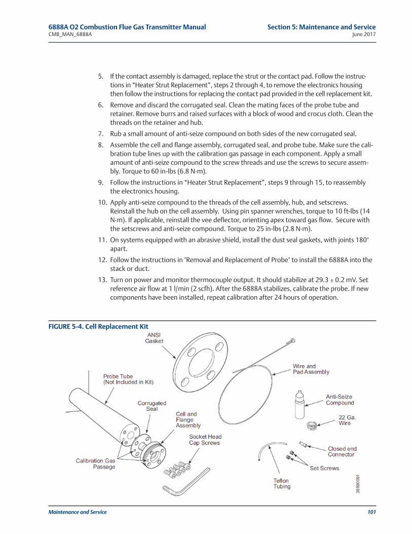
Maintenance and Service 101
5. If the contact assembly is damaged, replace the strut or the contact pad. Follow the instruc-tions in “Heater Strut Replacement”, steps 2 through 4, to remove the electronics housingthen follow the instructions for replacing the contact pad provided in the cell replacement kit.
6. Remove and discard the corrugated seal. Clean the mating faces of the probe tube andretainer. Remove burrs and raised surfaces with a block of wood and crocus cloth. Clean thethreads on the retainer and hub.
7. Rub a small amount of anti-seize compound on both sides of the new corrugated seal.
8. Assemble the cell and flange assembly, corrugated seal, and probe tube. Make sure the cali-bration tube lines up with the calibration gas passage in each component. Apply a smallamount of anti-seize compound to the screw threads and use the screws to secure assem-bly. Torque to 60 in-lbs (6.8 N·m).
9. Follow the instructions in “Heater Strut Replacement”, steps 9 through 15, to reassemblythe electronics housing.
10. Apply anti-seize compound to the threads of the cell assembly, hub, and setscrews.Reinstall the hub on the cell assembly. Using pin spanner wrenches, torque to 10 ft-lbs (14N·m). If applicable, reinstall the vee deflector, orienting apex toward gas flow. Secure withthe setscrews and anti-seize compound. Torque to 25 in-lbs (2.8 N·m).
11. On systems equipped with an abrasive shield, install the dust seal gaskets, with joints 180°apart.
12. Follow the instructions in "Removal and Replacement of Probe" to install the 6888A into thestack or duct.
13. Turn on power and monitor thermocouple output. It should stabilize at 29.3 ± 0.2 mV. Setreference air flow at 1 l/min (2 scfh). After the 6888A stabilizes, calibrate the probe. If newcomponents have been installed, repeat calibration after 24 hours of operation.
FIGURE 5-4. Cell Replacement Kit
6888A O2 Combustion Flue Gas Transmitter Manual Section 5: Maintenance and ServiceCMB_MAN_6888A June 2017

102 Maintenance and Service
5.10 Diffusion Element ReplacementThe diffusion element protects the cell from particles in process gases. Normally, it does not needto be replaced because the vee deflector protects it from particulate erosion.
In severe environments, the diffusion element may be broken or subject to excessive erosion.Examine the element whenever removing the probe for any purpose. Replace if damaged.
Damage to the diffusion element may become apparent during calibration. Compare proberesponse with previous response. A broken diffusion element will cause an inadequate response tocalibration gas. Hex wrenches needed to remove setscrews and socket head screws in the followingprocedure are available as part of a Probe Disassembly Kit, Table 6-1.
1. Follow the instructions in "Removal and Replacement of Probe" to remove the 6888A fromthe stack or duct.
2. Loosen setscrews using hex wrench from Probe Disassembly Kit and remove vee deflector.Inspect setscrews. If damaged, replace with stainless setscrews coated with anti-seize com-pound.
3. Follow the instructions in "Removal and Replacement of Probe" to install the 6888A into thestack or duct.
NOTE
This refers to the ceramic diffusion element only.
FIGURE 5-5. Ceramic Diffuser Element Replacement
Section 5: Maintenance and Service 6888A O2 Combustion Flue Gas Transmitter ManualJune 2017 CMB_MAN_6888A

5.11 Blind Cover ReplacementThis paragraph covers the replacement of the main housing cover and the application of the cor-rect field wiring label.
1. Remove existing cover from the Transmitter housing.
2. Select the new Field Wiring Label that matches the existing label on the inside of the oldcover. A graphic of each label and their application is shown in Figure 5-6.
3. Peel off the backing and attach the new label to the inside of the new cover.
4. Install the new cover onto the housing.
Maintenance and Service 103
6888A O2 Combustion Flue Gas Transmitter Manual Section 5: Maintenance and ServiceCMB_MAN_6888A June 2017
NOTEField wiring labels are supplied for each product configuration. Ensure the correct label is applied tothe inside of the cover that matches your configuration.
FIGURE 5-6. Field Wiring Labels

104 Maintenance and Service
Section 5: Maintenance and Service 6888A O2 Combustion Flue Gas Transmitter ManualJune 2017 CMB_MAN_6888A
This page left intentionally blank.

Replacement Parts 105
6888A O2 Combustion Flue Gas Transmitter Manual Section 6: Replacement PartsCMB_MAN_6888A June 2017
Section 6: Replacement Parts
6.1 6888A Transmitter
Part Number Description
6A00448G01 Kit, Transmitter Board
6A00448G02 Kit, Transmitter Board, w/Mounting Plate & Cover
6A00449G01 Kit, DR Terminal Board
6A00449G02 Kit, DR Terminal Board, w/Mounting Plate & Cover
6A00449G10 Kit, DR Terminal Board, YEW
6A00449G11 Kit, DR Terminal Board, YEW, w/Mounting Plate & Cover
6A00452G01 Kit, Blind Cover, Standard & Autocal Housing
6A00450G01 Kit, Cell Gaskets (Pack of 5)
6A00451G01 Kit, Cover O-Rings, Standard Hsg (Pack of 5)
6A00453G01 Kit, Snubber Diffuser
6A00453G02 Kit, Snubber Diffuser w/Dust Seal
6A00453G03 Kit, Ceramic Diffuser w/V-deflector
6A00453G04 Kit, Ceramic Diffuser w/Dust Seal w/V-deflector
6A00453G05 Kit, Hastelloy Diffuser w/V-deflector
6A00453G06 Kit, Hastelloy Diffuser w/Dust Seal w/V-deflector
6A00454G01 Kit, Strut, 18 Inch
6A00454G02 Kit, Strut, 3 Foot
6A00454G03 Kit, Strut, 6 Foot
6A00454G04 Kit, Strut, 9 Foot
6A00454G05 Kit, Strut, 12 Foot
6A00455G01 Kit, Cell Replacement, 18 Inch, Standard Cell
6A00455G02 Kit, Cell Replacement, 3 Foot, Standard Cell
6A00455G03 Kit, Cell Replacement, 6 Foot, Standard Cell
6A00455G04 Kit, Cell Replacement, 9 Foot, Standard Cell
6A00455G05 Kit, Cell Replacement, 12 Foot, Standard Cell
6A00455G11 Kit, Cell Replacement, 18 Inch, Acid Resistant Cell
6A00455G12 Kit, Cell Replacement, 3 Foot, Acid Resistant Cell
6A00455G13 Kit, Cell Replacement, 6 Foot, Acid Resistant Cell
6A00455G14 Kit, Cell Replacement, 9 Foot, Acid Resistant Cell
6A00455G15 Kit, Cell Replacement, 12 Foot, Acid Resistant Cell
6A00456G01 Flange Gasket Kit, ANSI, General Purpose, (Pack of 5)
6A00456G03 Flange Gasket Kit, DIN, General Purpose, (Pack of 5)
6A00457G01 Spare transmitter board cover
6A00457G02 Spare DR term board cover
6A00475G01 Tool kit - 6888A
TABLE 6-1. Replacement Part Kits for O2 Transmitter

106 Replacement Parts
Section 6: Replacement Parts 6888A O2 Combustion Flue Gas Transmitter ManualJune 2017 CMB_MAN_6888A
Part Number Description
1A99119G01 Calibration Gas Bottles - 0.4% and 8% O2, balance nitrogen - 550 liters each*
1A99119G02 Two Flow Regulators (for calibration gas bottles)
1A99119G03 Bottle rack
TABLE 6-1. Replacement Part Kits for O2 Transmitter
*Calibration gas bottles cannot be shipped via air freight

Optional Accessories 107
Section 7: Optional Accessories
7.1 Asset Management Solutions (AMS)Asset Management Solutions (AMS) software works in conjunction with the HARTCommunication Protocol and offers the capability to communicate with all HART plant devicesfrom a single computer terminal.
For more information, call Rosemount at 1-800-433-6076.
7.2 By-Pass PackagesThe specially designed Rosemount By-Pass Package for oxygen analyzers has proven to withstandthe high temperatures in process heaters while providing the same advantages offered by the insitu sensor. Inconel steel tubes provide effective resistance to corrosion, and the package uses nomoving parts, air pumps, or other components common to other sampling systems.
For more information, call Rosemount at 1-800-433-6076.
6888A O2 Combustion Flue Gas Transmitter Manual Section 7: Optional AccessoriesCMB_MAN_6888A June 2017

108 Optional Accessories
7.3 SPS 4001B Single Probe Autocalibration Sequencer
Rosemount specifically designed the SPS 4001B Single Probe Autocalibration Sequencer to pro-vide the capability to perform automatic or on-demand calibrations. The SPS 4001B is fullyenclosed in a NEMA cabinet suited for wall-mounting. This cabinet provides added protectionagainst dust and minor impacts.
The SPS 4001B works in conjunction with the 6888Xi, eliminating out-of-calibration occurrencesand the need to send a technician to the installation site.
For more information, call Rosemount Analytical at 1-800-433-6076.
FIGURE 7-2. Bypass Packages
FIGURE 7-3. SPS 4001B
Section 7: Optional Accessories 6888A O2 Combustion Flue Gas Transmitter ManualJune 2017 CMB_MAN_6888A

Optional Accessories 109
6888A O2 Combustion Flue Gas Transmitter Manual Section 7: Optional AccessoriesCMB_MAN_6888A June 2017
7.4 IMPS 4000 Intelligent Multiprobe Test Gas Sequencer
The IMPS 4000 Intelligent Multiprobe Test Gas Sequencer is housed within an IP56 (NEMA 4X)enclosure and has the intelligence to provide calibration gas sequencing of up to four 6888Xi’sto accommodate automatic and semi-automatic calibration routines.
This sequencer works in conjunction with the CALIBRATION RECOMMENDED feature, eliminat-ing out-of-calibration occurrences and the need to send a technician to the installation site. Inaddition, the IMPS 4000 provides a remote contact input to initiate a calibration from a remotelocation and relay outputs to alert when a calibration is in progress, an O2 Probe is out of calibra-tion, calibration gases are on, and calibration gas pressure is low.
For more information, call Rosemount at 1-800-433-6076.
FIGURE 7-4. IMPS 4000 Intelligent Multiprobe Sequencer

110 Optional Accessories
Section 7: Optional Accessories 6888A O2 Combustion Flue Gas Transmitter ManualJune 2017 CMB_MAN_6888A
7.5 O2 Calibration GasRosemount's O2 Calibration Gas and Service Kits have been carefully designed to provide a moreconvenient and fully portable means of testing, calibrating, and servicing.
Rosemount’s oxygen analyzers. These lightweight, disposable gas cylinders eliminate the needto rent gas bottles.
For more information, call Rosemount at 1-800-433-6076.
FIGURE 7-5. Calibration Gas Bottles
7.6 Oxybalance Display And Averaging SystemOptional OxyBalance Display and Averaging System. Reviews up to eight 4-20 mA signals fromindividual probes. Trends individual outputs, calculates four programmable averages as addi-tional 4-20 mA outputs.
For more information, call Rosemount at 1-800-433-6076.
FIGURE 7-6. OxyBalance System

Optional Accessories 111
6888A O2 Combustion Flue Gas Transmitter Manual Section 7: Optional AccessoriesCMB_MAN_6888A June 2017
Appendix A: Safety Data
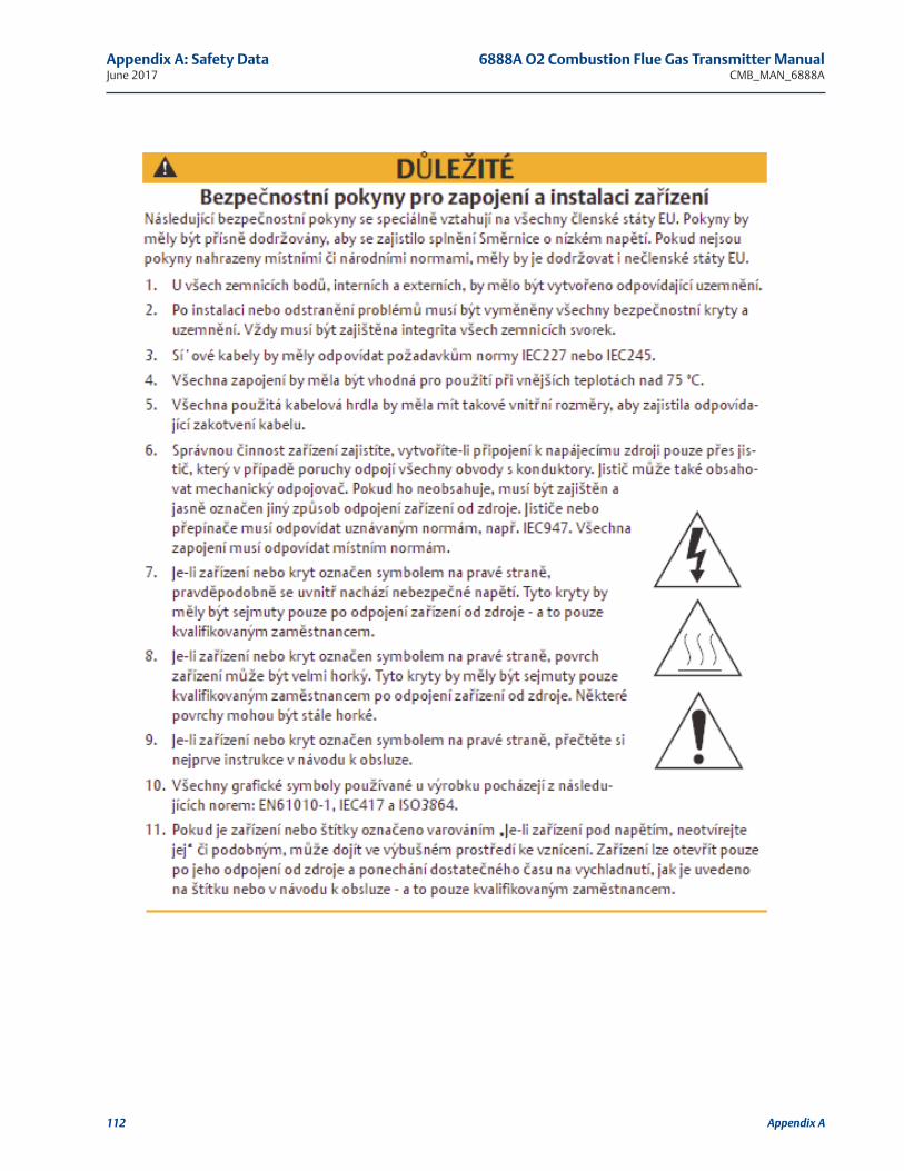
112 Appendix A
Appendix A: Safety Data 6888A O2 Combustion Flue Gas Transmitter ManualJune 2017 CMB_MAN_6888A

Appendix A 113
6888A O2 Combustion Flue Gas Transmitter Manual Appendix A: Safety DataCMB_MAN_6888A June 2017

114 Appendix A
Appendix A: Safety Data 6888A O2 Combustion Flue Gas Transmitter ManualJune 2017 CMB_MAN_6888A

Appendix A 115
6888A O2 Combustion Flue Gas Transmitter Manual Appendix A: Safety DataCMB_MAN_6888A June 2017

116 Appendix A
Appendix A: Safety Data 6888A O2 Combustion Flue Gas Transmitter ManualJune 2017 CMB_MAN_6888A

Appendix A 117
6888A O2 Combustion Flue Gas Transmitter Manual Appendix A: Safety DataCMB_MAN_6888A June 2017

118 Appendix A
Appendix A: Safety Data 6888A O2 Combustion Flue Gas Transmitter ManualJune 2017 CMB_MAN_6888A

Appendix A 119
6888A O2 Combustion Flue Gas Transmitter Manual Appendix A: Safety DataCMB_MAN_6888A June 2017

120 Appendix A
Appendix A: Safety Data 6888A O2 Combustion Flue Gas Transmitter ManualJune 2017 CMB_MAN_6888A

Appendix A 121
6888A O2 Combustion Flue Gas Transmitter Manual Appendix A: Safety DataCMB_MAN_6888A June 2017
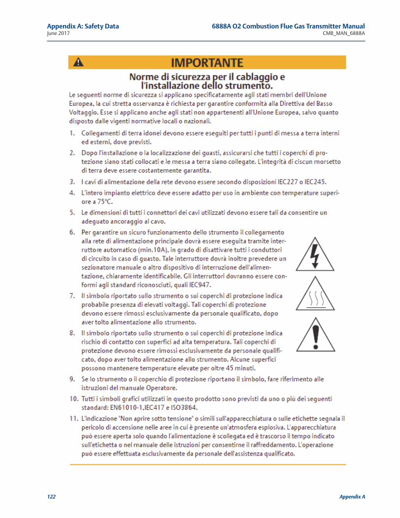
122 Appendix A
Appendix A: Safety Data 6888A O2 Combustion Flue Gas Transmitter ManualJune 2017 CMB_MAN_6888A

Appendix A 123
6888A O2 Combustion Flue Gas Transmitter Manual Appendix A: Safety DataCMB_MAN_6888A June 2017

124 Appendix A
Appendix A: Safety Data 6888A O2 Combustion Flue Gas Transmitter ManualJune 2017 CMB_MAN_6888A

Appendix A 125
6888A O2 Combustion Flue Gas Transmitter Manual Appendix A: Safety DataCMB_MAN_6888A June 2017

126 Appendix A
Appendix A: Safety Data 6888A O2 Combustion Flue Gas Transmitter ManualJune 2017 CMB_MAN_6888A

Appendix A 127
6888A O2 Combustion Flue Gas Transmitter Manual Appendix A: Safety DataCMB_MAN_6888A June 2017

128 Appendix A
Appendix A: Safety Data 6888A O2 Combustion Flue Gas Transmitter ManualJune 2017 CMB_MAN_6888A

Appendix A 129
6888A O2 Combustion Flue Gas Transmitter Manual Appendix A: Safety DataCMB_MAN_6888A June 2017
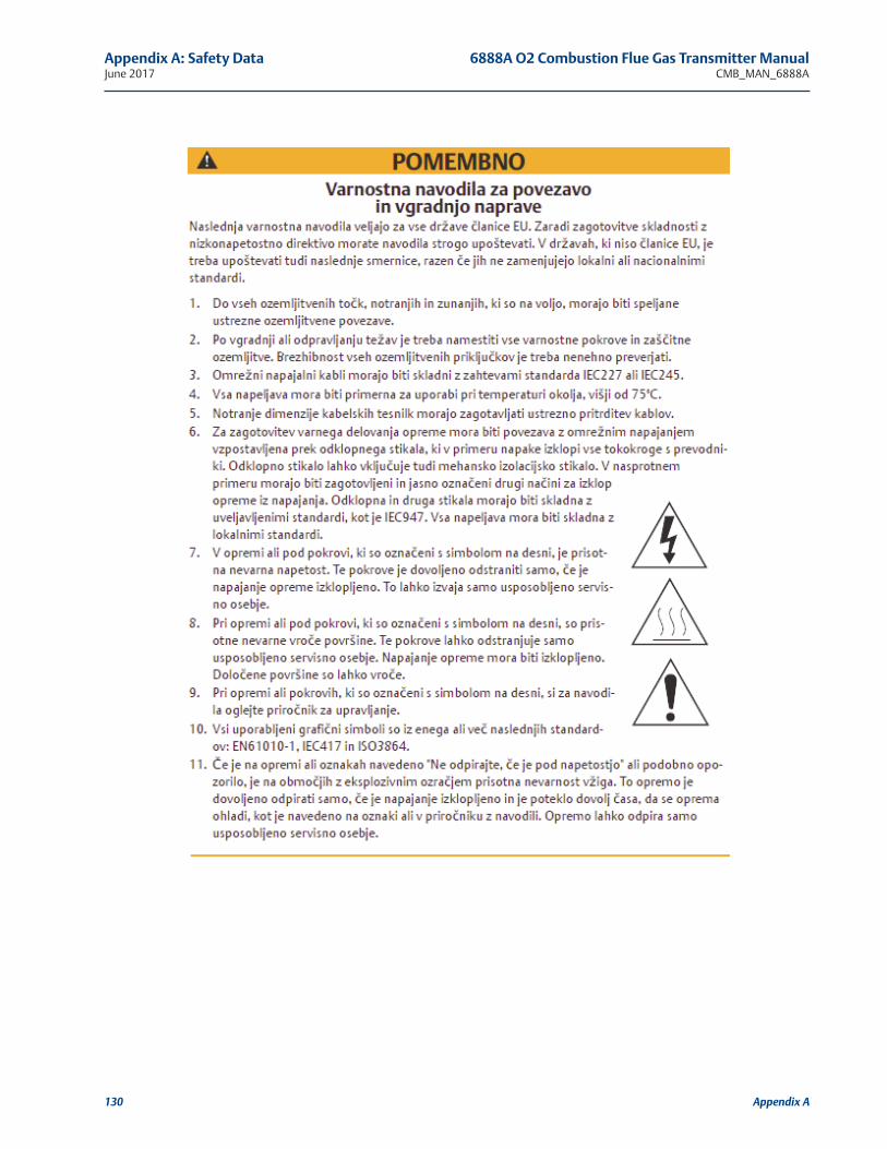
130 Appendix A
Appendix A: Safety Data 6888A O2 Combustion Flue Gas Transmitter ManualJune 2017 CMB_MAN_6888A

Appendix A 131
6888A O2 Combustion Flue Gas Transmitter Manual Appendix A: Safety DataCMB_MAN_6888A June 2017

Appendix A: Safety Data 6888A O2 Combustion Flue Gas Transmitter ManualJune 2017 CMB_MAN_6888A
132 Appendix A

6888A O2 Combustion Flue Gas Transmitter Manual Appendix B: Return of MaterialCMB_MAN_6888A June 2017
Appendix B 133
B.1 Returning Material
SERVICE SUPPORT - To expedite the return process outside of the United States, contact thenearest Emerson representative. Within the United States, call the Emerson Instrument andValves Response Center using the 1-800-654-RSMT (7768) toll-free number. This center, avail-able 24 hours a day, will assist you with any needed information or materials. The center will askfor product model and serial numbers, and will provide a Return Material Authorization (RMA)number. The center will also ask for the process material to which the product was last exposed.Emerson Instrument and Valves Response Center representatives will explain the additional infor-mation and procedures necessary to return goods exposed to hazardous substances.
Appendix B: Return of Material

134 Appendix B: Return of Material
Appendix B: Return of Material 6888A O2 Combustion Flue Gas Transmitter ManualJune 2017 CMB_MAN_6888A

Appendix C: Product Certifications 135
6888A O2 Combustion Flue Gas Transmitter Manual Appendix C: Product CertificationsCMB_MAN_6888A June 2017
C.1 European Directive InformationA copy of the EC Declaration of Conformity can be found at the end of the Quick Start Guide.The most recent revision of the EC Declaration of Conformity can be found atEmerson.com/Rosemount.
C.2 Ordinary Location CertificationAs standard, the transmitter has been examined and tested to determine that the design meetsthe basic electrical, mechanical, and fire protection requirements by a nationally recognized testlaboratory (NRTL) as accredited by the Federal Occupational Safety and Health Administration(OSHA).
C.3 Installing Equipment in North AmericaThe US National Electrical Code (NEC) and the Canadian Electrical Code (CEC) permit the use ofDivision marked equipment in Zones and Zone marked equipment in Divisions. The markingsmust be suitable for the area classification, gas, and temperature class. This information is clearlydefined in the respective codes.
C.4 Rosemount 6888A In-Situ Oxygen Transmitter for General Purpose Locations
C.4.1 USAFM
Certificate: 3042889
Standards: FM 3810: 2005, ANSI/EC 250: 2003, ANSI/EC 60529: 2004
Markings: Type 4X, IP66
Special Conditions for Use: Type 4X and IP66 applies to the transmitter portion that is mountedexternally to the flue duct.
C.4.1 CanadaCSA
Certificate: 1913435
Standards: CAN//CSA C22.2 No. 61010-1-04, UL 61010-1:2004 (2nd Edition), CAN/CSA-E60079-0:07, CAN/CSA-E60079-1:07, CAN/CSA-C22.2 No.94-M91 (R2001), CAN/CSA C22.2 No.60529:05, ANSI/ISA-12.00.01-2005 (IEC 60079-0 Mod), ANSI/ISA-12.22.01-2005 (IEC 60079-1Mod), UL 50 (11th Ed.), IEC 60529 (Edition 2.1-2001-02), NEMA 250-2003
Markings: Type 4X, IP66
Appendix C: Product Certifications

136 Appendix C: Product Certifications
Appendix C: Product Certifications 6888A O2 Combustion Flue Gas Transmitter ManualJune 2017 CMB_MAN_6888A
C.4.1 EuropeTUVRheinland QAL1
Certificate: 0000038506
Standards: EN15267-1:2009, EN15627-2:2009, EN15627-3:2007, EN14181:2004
MCERTS
Certificate: Sira MC140270/00
Standards: EN15267-1:2009, EN15627-2:2009, EN15627-3:2007, EN14181:2004

Appendix C: Product Certifications 137
6888A O2 Combustion Flue Gas Transmitter Manual Appendix C: Product CertificationsCMB_MAN_6888A June 2017

CMB-MAN-6888ARev. C
June 2017
Emerson Automation Solutions
8200 Market BoulevardChanhassen, MN 55317,USA Tel +1 800 999 9307Fax +1 952 949 [email protected]
Youtube.com/user/RosemountMeasurement
Twitter.com/Rosemount_News
Analyticexpert.com
facebook.com/Rosemount
©2017 Emerson Automation Solutions. All rights reserved.
The Emerson logo is a trademark and service mark of Emerson Electric Co. Rosemount is a mark ofone of the Emerson family of companies. All other marks are the property of their respectiveowners.
The contents of this publication are presented for information purposes only, and while effort hasbeen made to ensure their accuracy, they are not to be construed as warranties or guarantees,expressed or implied, regarding the products or services described herein or their use or applica-bility. All sales are governed by our terms and conditions, which are available on request. Wereserve the right to modify or improve the designs or specifications of our products at any timewithout notice.
www.Emerson.com/RosemountGasAnalysis