mann+hummel air cleaners - interempresas...air cleaners for two-way ventilation, silencer air...
TRANSCRIPT
MANN+HUMMEL Air Cleaners
2 | Air cleaners for many fields of application
Air cleaners for many fields of application
Important information for our customers
We are continually developing our range of filters to further improve our high perfor-mance, economic filtration products. For this reason we expressly reserve the
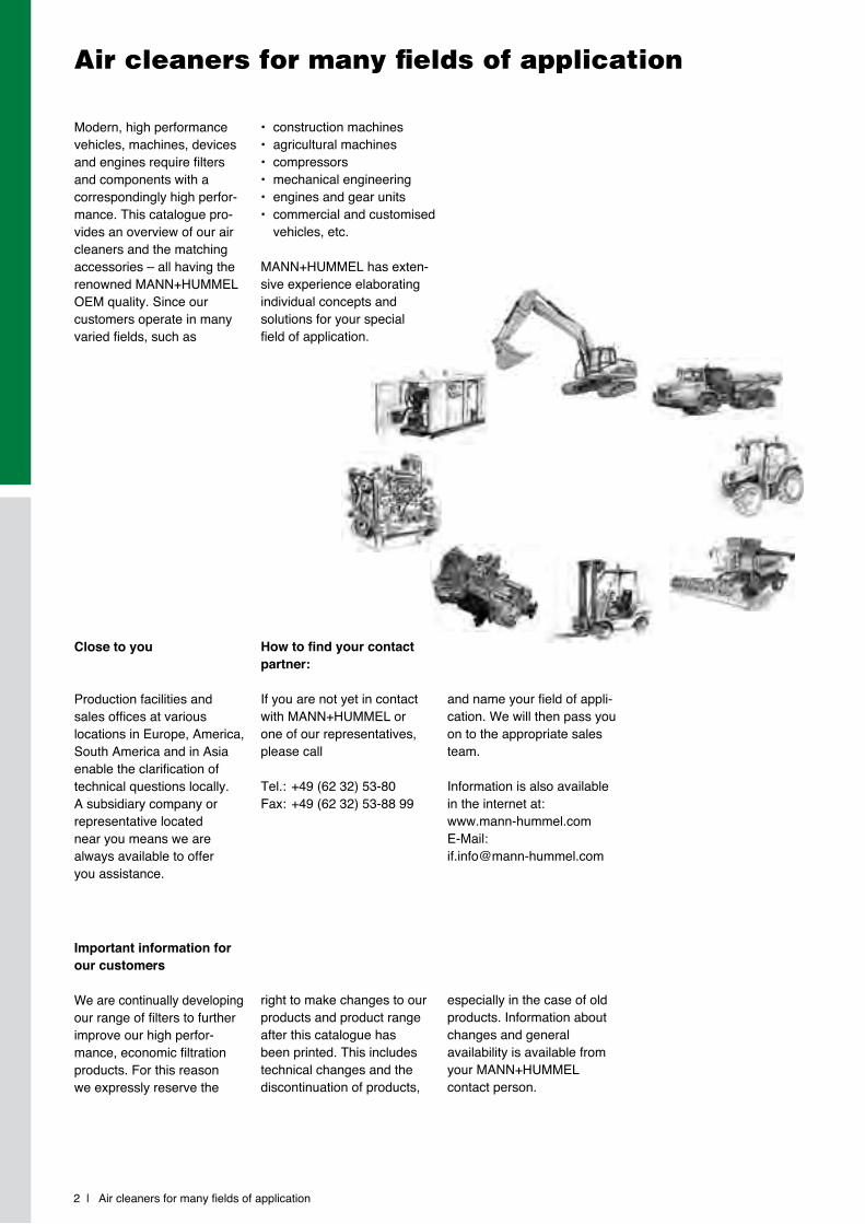
Modern, high performance vehicles, machines, devices and engines require filters and components with a correspondingly high perfor-mance. This catalogue pro-vides an overview of our air cleaners and the matching accessories – all having the renowned MANN+HUMMEL OEM quality. Since our customers operate in many varied fields, such as
Close to you
Production facilities and sales offices at various locations in Europe, America, South America and in Asia enable the clarification of technical questions locally. A subsidiary company or representative located near you means we are always available to offer you assistance.
right to make changes to our products and product range after this catalogue has been printed. This includes technical changes and the discontinuation of products,
• construction machines• agricultural machines• compressors• mechanical engineering• engines and gear units• commercial and customised vehicles, etc.
MANN+HUMMEL has exten-sive experience elaborating individual concepts and solutions for your special field of application.
How to find your contact partner:
If you are not yet in contact with MANN+HUMMEL or one of our representatives, please call
Tel.: +49 (62 32) 53-80Fax: +49 (62 32) 53-88 99
especially in the case of old products. Information about changes and general availability is available from your MANN+HUMMEL contact person.
and name your field of appli-cation. We will then pass you on to the appropriate sales team.
Information is also available in the internet at:www.mann-hummel.comE-Mail: [email protected]
Contents | 3
Contents
Page
Company profile 2
Contents 3
Product overview 4
IQORON 9
IQORON-V / IQORON-S 20
ENTARON XD 27
EuROPIClON 35
NlG 51
NLG Pico 52
NLG Piclon 53
NLG DualSpin Combination air cleaners 53
Piclon 69
Picolino 79
Picolight 87
Vacuum air cleaners 91
Air cleaners for two-way ventilation, silencer air cleaners 95
Accessories for air cleaners 99
Rain caps 100
Precleaners 102
Air connecting parts 104
Ejectors 112
Service switches / service indicators 115
Technical Appendix 119
Glossary 120
Filter configuration 122
Servicing and installation instructions 126
Conversion table 128
Product overview
4 | Product overview
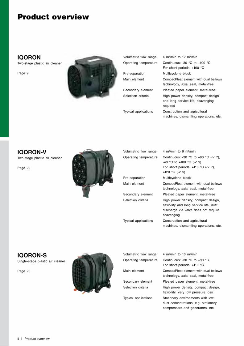
Volumetric flow range 4 m³/min to 12 m³/minOperating temperature Continuous: -30 °C to +100 °C
For short periods: +100 °CPre-separation Multicyclone blockMain element CompacPleat element with dual bellows
technology, axial seal, metal-freeSecondary element Pleated paper element, metal-freeSelection criteria High power density, compact design
and long service life, scavenging required
Typical applications Construction and agricultural machines, dismantling operations, etc.
Volumetric flow range 4 m³/min to 9 m³/minOperating temperature Continuous: -30 °C to +90 °C (-V 7),
-40 °C to +100 °C (-V 9) For short periods: +110 °C (-V 7), +120 °C (-V 9)
Pre-separation Multicyclone blockMain element CompacPleat element with dual bellows
technology, axial seal, metal-freeSecondary element Pleated paper element, metal-freeSelection criteria High power density, compact design,
flexibility and long service life, dust discharge via valve does not require scavenging
Typical applications Construction and agricultural machines, dismantling operations, etc.
Volumetric flow range 4 m³/min to 10 m³/minOperating temperature Continuous: -30 °C to +90 °C
For short periods: +110 °CMain element CompacPleat element with dual bellows
technology, axial seal, metal-freeSecondary element Pleated paper element, metal-freeSelection criteria High power density, compact design,
flexibility, very low pressure lossTypical applications Stationary environments with low
dust concentrations, e.g. stationary compressors and generators, etc.
IQORON Two-stage plastic air cleaner
Page 9
IQORON-V Two-stage plastic air cleaner
Page 20
IQORON-S Single-stage plastic air cleaner
Page 20
Product overview | 5
Product overview
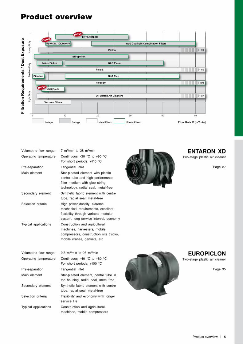
0 10 20 30 40 50
1-stage 2-stage
Lig
ht D
uty
Mediu
m D
uty
Heavy D
uty
Fil
tra
tio
n R
eq
uir
em
en
ts /
Du
st
Ex
po
su
re
Metal Filters Plastic Filters Flow Rate V [m³/min] .
gy
yy
y
Oil-wetted Air Cleaners
IQORON-S
Picolight
NLG PicoPicolino
NLG Piclon
Pico-E
Inline Piclon
Europiclon
Piclon
NLG DualSpin Combination FiltersIQORON / IQORON-V
ENTARON XD
90
60
100
87
Vacuum Filters
IIIQIQO
IIQIQIQIQOORORO
EENEN
Volumetric flow range 7 m³/min to 28 m³/minOperating temperature Continuous: -30 °C to +90 °C
For short periods: +110 °CPre-separation Tangential inletMain element Star-pleated element with plastic
centre tube and high performance filter medium with glue string technology, radial seal, metal-free
Secondary element Synthetic fabric element with centre tube, radial seal, metal-free
Selection criteria High power density, extreme mechanical requirements, excellent flexibility through variable modular system, long service interval, economy
Typical applications Construction and agricultural machines, harvesters, mobile compressors, construction site trucks, mobile cranes, gensets, etc
Volumetric flow range 0.8 m3/min to 28 m3/minOperating temperature Continuous: -40 °C to +80 °C
For short periods: +100 °CPre-separation Tangential inletMain element Star-pleated element, centre tube in
the housing, radial seal, metal-freeSecondary element Synthetic fabric element with centre
tube, radial seal, metal-freeSelection criteria Flexibility and economy with longer
service lifeTypical applications Construction and agricultural
machines, mobile compressors
ENTARON XDTwo-stage plastic air cleaner
Page 27
EuROPIClONTwo-stage plastic air cleaner
Page 35
Product overview
6 | Product overview
Volumetric flow range 10 m3/min to 45 m3/minOperating temperature Continuous: -40 °C to +80 °C
For short periods: +100 °CMain element Star-pleated element with centre tube,
radial seal, metal-freeSecondary element Synthetic fabric element with centre
tube, radial seal, metal-freeSelection criteria Low pressure drop and highly
economical with low dust loadsTypical applications Trucks, mobile cranes, buses,
stationary compressors, generators
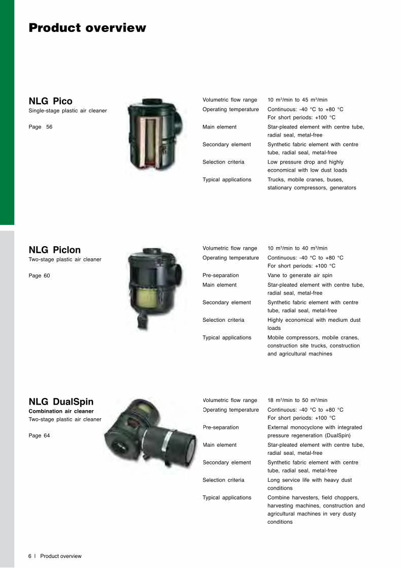
NlG Pico Single-stage plastic air cleaner
Page 56
Volumetric flow range 10 m3/min to 40 m3/minOperating temperature Continuous: -40 °C to +80 °C
For short periods: +100 °CPre-separation Vane to generate air spinMain element Star-pleated element with centre tube,
radial seal, metal-freeSecondary element Synthetic fabric element with centre
tube, radial seal, metal-freeSelection criteria Highly economical with medium dust
loadsTypical applications Mobile compressors, mobile cranes,
construction site trucks, construction and agricultural machines
NlG Piclon Two-stage plastic air cleaner
Page 60
Volumetric flow range 18 m3/min to 50 m3/minOperating temperature Continuous: -40 °C to +80 °C
For short periods: +100 °CPre-separation External monocyclone with integrated
pressure regeneration (DualSpin)Main element Star-pleated element with centre tube,
radial seal, metal-freeSecondary element Synthetic fabric element with centre
tube, radial seal, metal-freeSelection criteria Long service life with heavy dust
conditionsTypical applications Combine harvesters, field choppers,
harvesting machines, construction and agricultural machines in very dusty conditions
NlG DualSpinCombination air cleanerTwo-stage plastic air cleaner
Page 64
Product overview | 7
Product overview
Volumetric flow range 0.25 m3/min to 3.5 m3/minOperating temperature Continuous: -30 °C to +100 °C
For short periods: +120 °CFilter element Star-pleated element, radial seal,
metal-freeTypical applications Filters for two-way ventilation, small
engines, small piston compressors, general mechanical engineering
Volumetric flow range 2 m3/min to 90 m3/minOperating temperature Continuous: -40 °C to +100 °C
For short periods: +120 °CPre-separation Vane to generate air spinMain element Star-pleated element with centre tube,
axial seal, reinforced with metalSecondary element Synthetic fabric element with centre
tube, axial seal, rein-forced with metalSelection criteria Long service life with very high
mechanical stress on the housingTypical applications Construction and agricultural machines,
engine construction
Volumetric flow range 1 m3/min to 100 m3/minOperating temperature Continuous: -30 °C to +80 °C
For short periods: +100 °CFilter element Star-pleated element, radial seal,
metal-freeTypical applications Stationary compressors, generators,
marine applications
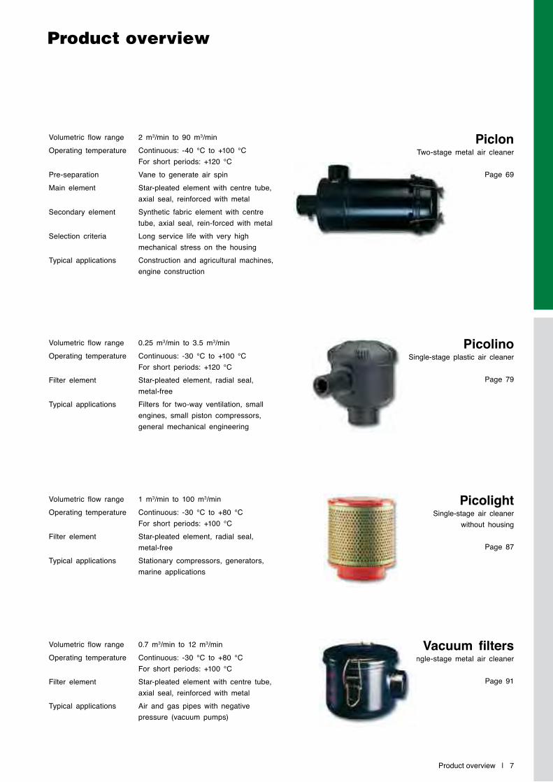
PicolightSingle-stage air cleaner
without housing
Page 87
Volumetric flow range 0.7 m3/min to 12 m3/minOperating temperature Continuous: -30 °C to +80 °C
For short periods: +100 °CFilter element Star-pleated element with centre tube,
axial seal, reinforced with metalTypical applications Air and gas pipes with negative
pressure (vacuum pumps)
Vacuum filtersSingle-stage metal air cleaner
Page 91
PiclonTwo-stage metal air cleaner
Page 69
PicolinoSingle-stage plastic air cleaner
Page 79
Other air cleaners*
8 | Product overview
* These air cleaners remain available. Please contact your MANN+HUMMEL contact person for technical details.
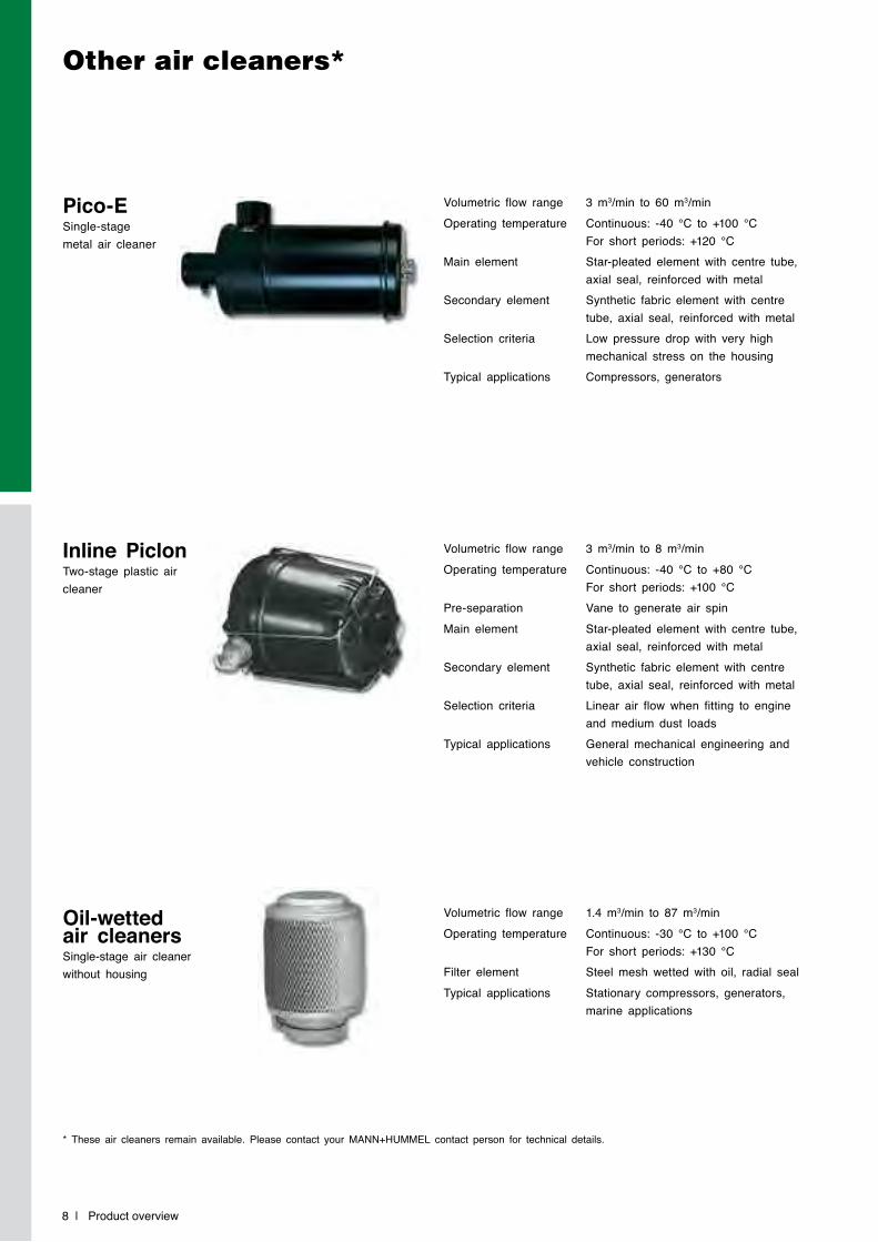
Volumetric flow range 3 m3/min to 60 m3/minOperating temperature Continuous: -40 °C to +100 °C
For short periods: +120 °CMain element Star-pleated element with centre tube,
axial seal, reinforced with metalSecondary element Synthetic fabric element with centre
tube, axial seal, reinforced with metalSelection criteria Low pressure drop with very high
mechanical stress on the housingTypical applications Compressors, generators
Volumetric flow range 3 m3/min to 8 m3/minOperating temperature Continuous: -40 °C to +80 °C
For short periods: +100 °CPre-separation Vane to generate air spinMain element Star-pleated element with centre tube,
axial seal, reinforced with metalSecondary element Synthetic fabric element with centre
tube, axial seal, reinforced with metalSelection criteria Linear air flow when fitting to engine
and medium dust loadsTypical applications General mechanical engineering and
vehicle construction
Volumetric flow range 1.4 m3/min to 87 m3/minOperating temperature Continuous: -30 °C to +100 °C
For short periods: +130 °CFilter element Steel mesh wetted with oil, radial sealTypical applications Stationary compressors, generators,
marine applications
Pico-E Single-stage metal air cleaner
Inline Piclon Two-stage plastic air cleaner
Oil-wetted air cleanersSingle-stage air cleaner without housing
Iqoron | 9
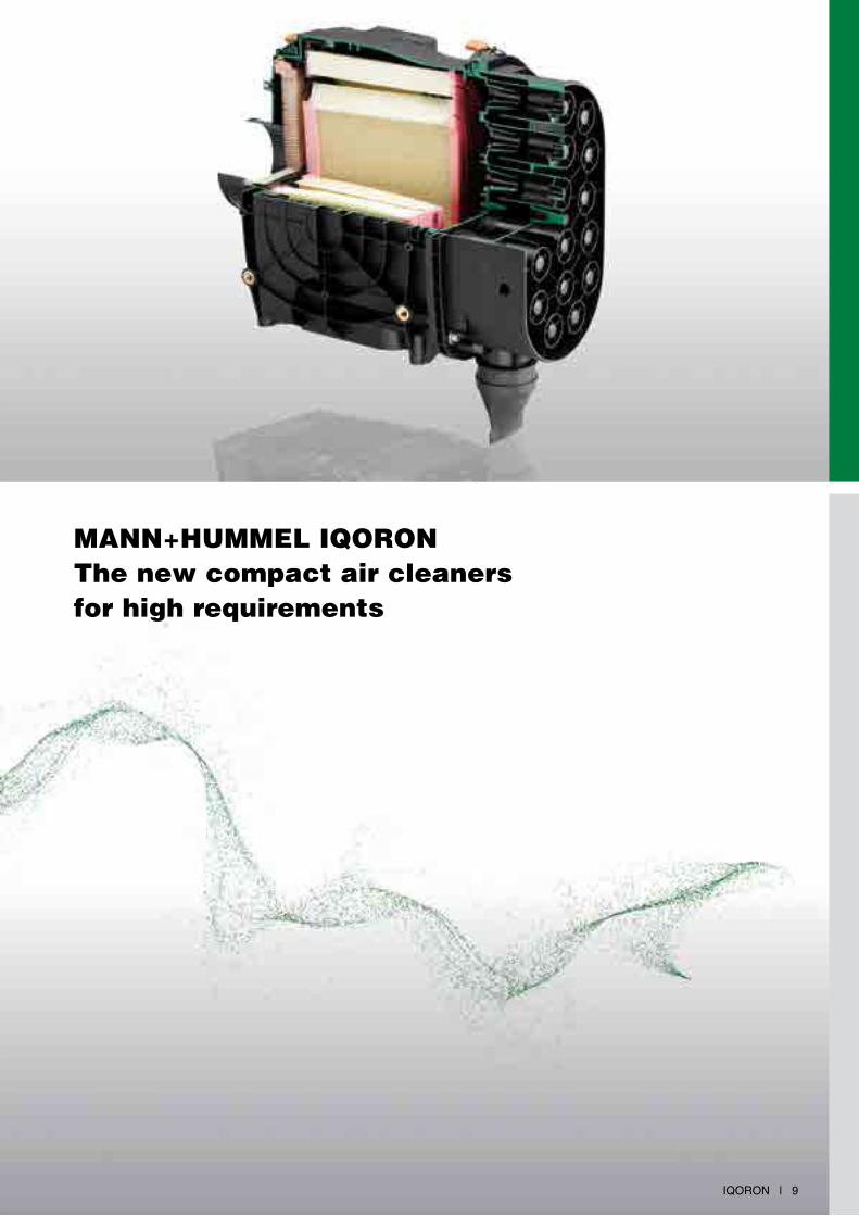
MANN+HUMMEL IqoroN The new compact air cleanersfor high requirements

10 | Iqoron
IqoroN IqoroN-V IqoroN-S
IqoroNAn intelligent solution
The newly developed IQORON air cleaner series from MANN+HUMMEL meets current and future requirements for greater air throughput and reduced installation space and is therefore the ideal solution for demanding applications.
Advantages at a glance:
• low space requirement through compact design
• long filter service life through highly efficient multi-cyclone block pre-cleaner and the CompacPleat double-bellows element
• highest reliability through filter element with axial seal and additional secondary element with radial seal
• inline air flow enables numerous installation possibilities
• easy monitoring of the dirt accumulation level through integrated connection for service switch
• cleaning of multi-cyclone block made easy through central fixing screw
• eco-friendly disposal of metal-free filter element (fully incinerable)
• problem-free fitting to different units through variable installation positions
• quick first-fit through various fixing possibilities
Variations of the IqoroN series
IqoroN
The power pack: with a high power density and long service life – scavenging required
Dimensions and part numbers on page 16.
IqoroN-V
High performance cyclone technology – without scavenging
Dimensions and part numbers on page 22.
IqoroN-S
The single-stage filter for low pressure drop
Dimensions and part numbers on page 21.
Target applications
Iqoron | 11
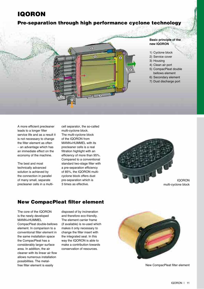
New CompacPleat filter element
The core of the Iqoron is the newly developed MAnn+HUMMEL CompacPleat double-bellows element. In comparison to a conventional filter element in the same installation space the CompacPleat has a considerably larger surface area. In addition, the air cleaner with its linear air flow allows numerous installation possibilities. The metal-free filter element is easily
disposed of by incineration and therefore eco-friendly. The element carrier frame (if available) is re-used which makes it only necessary to change the filter insert with the integrated seal. In this way the Iqoron is able to make a contribution towards conservation of resources.
1) Cyclone block2) Service cover3) Housing4) Clean air port5) CompacPleat double bellows element6) Secondary element7) Dust discharge port
Basic principle of the new IQORON
new CompacPleat filter element
IqoroNPre-separation through high performance cyclone technology
A more efficient precleaner leads to a longer filter service life and as a result it is not necessary to change the filter element as often – an advantage which has an immediate effect on the economy of the machine.
The best and most technically advanced solution is achieved by the connection in parallel of many small, separate precleaner cells in a multi-
cell separator, the so-called multi-cyclone block.The multi-cyclone block of the Iqoron from MAnn+HUMMEL with its precleaner cells is a real filtration highlight with an efficiency of more than 95%. Compared to a conventional standard two-stage filter with a pre-separation efficiency of 85%, the Iqoron multi-cyclone block offers dust pre-separation which is 3 times as effective.
Iqoron multi-cyclone block

12 | Iqoron
IqoroN
The Iqoron is a two-stage air cleaner with a highly efficient cyclone block. The cleaner is scavenged continuously to fully exploit its efficiency of more than 95% (see page 15).
Service cover
Integrated mounting bracket (with Iqoron 10 and 12 side mounting is also possible)
Cyclone precleaner
Dust discharge port (for scavenging)
The inline concept of the IqoroN
A filter for tight installation conditions
A size comparison with a conventional filter and same service life shows: Iqoron saves valuable installation space!
Air flow in the new Iqoron air cleaner Air flow in a conventional air cleaner
clean air to the engine
filter change
filter change
dirty ambient air
dirty ambient air
clean air to the
engine
Housing in fibre-glass reinforced plastic (polyamid)
Clean air port
IqoroNDetails
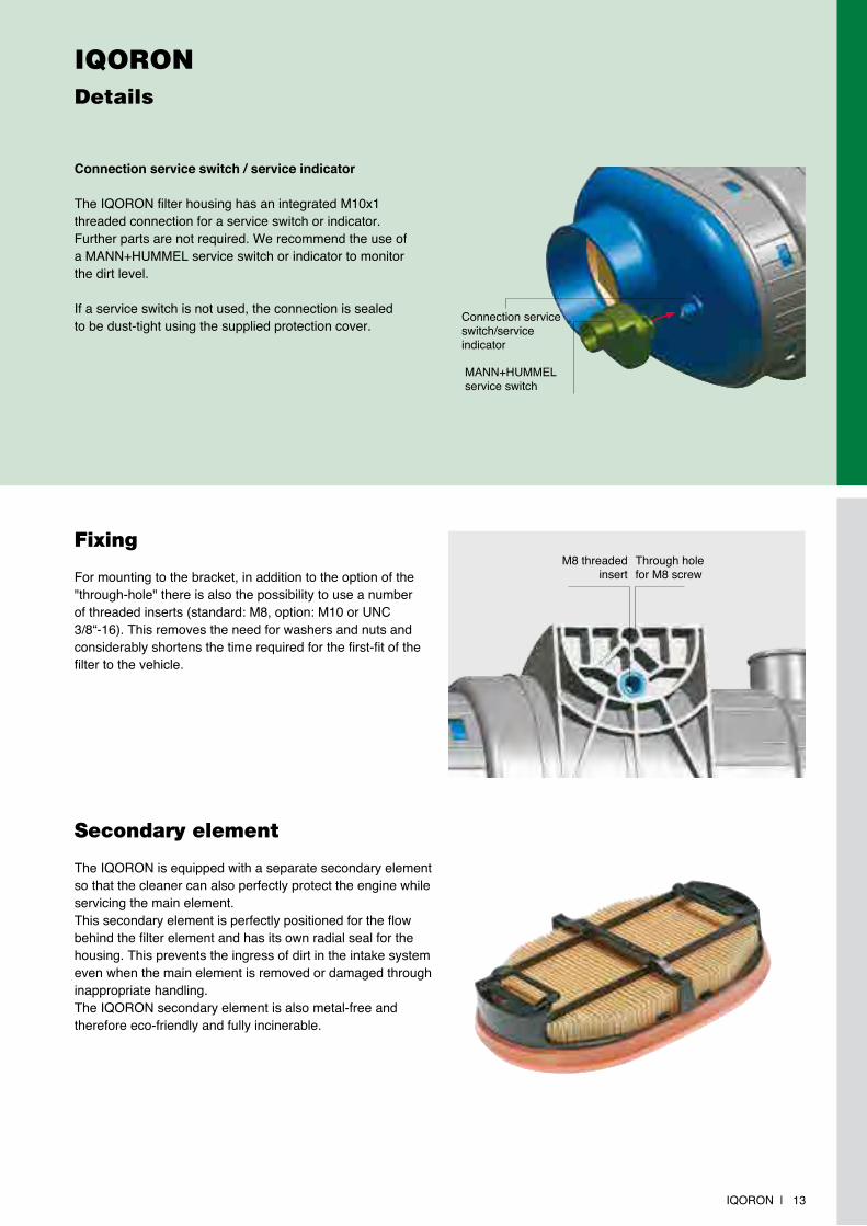
Connection service switch / service indicator
The Iqoron filter housing has an integrated M10x1 threaded connection for a service switch or indicator. Further parts are not required. We recommend the use of a MAnn+HUMMEL service switch or indicator to monitor the dirt level.
If a service switch is not used, the connection is sealed to be dust-tight using the supplied protection cover.
Fixing
For mounting to the bracket, in addition to the option of the "through-hole" there is also the possibility to use a number of threaded inserts (standard: M8, option: M10 or UnC 3/8“-16). This removes the need for washers and nuts and considerably shortens the time required for the first-fit of the filter to the vehicle.
Iqoron | 13
Secondary element
The Iqoron is equipped with a separate secondary element so that the cleaner can also perfectly protect the engine while servicing the main element.This secondary element is perfectly positioned for the flow behind the filter element and has its own radial seal for the housing. This prevents the ingress of dirt in the intake system even when the main element is removed or damaged through inappropriate handling.The Iqoron secondary element is also metal-free and therefore eco-friendly and fully incinerable.
M8 threaded insert
Connection service switch/service indicator
MAnn+HUMMELservice switch
Through hole for M8 screw
14 | Iqoron
IqoroNInstallation and maintenance
IQORON 10 and 12
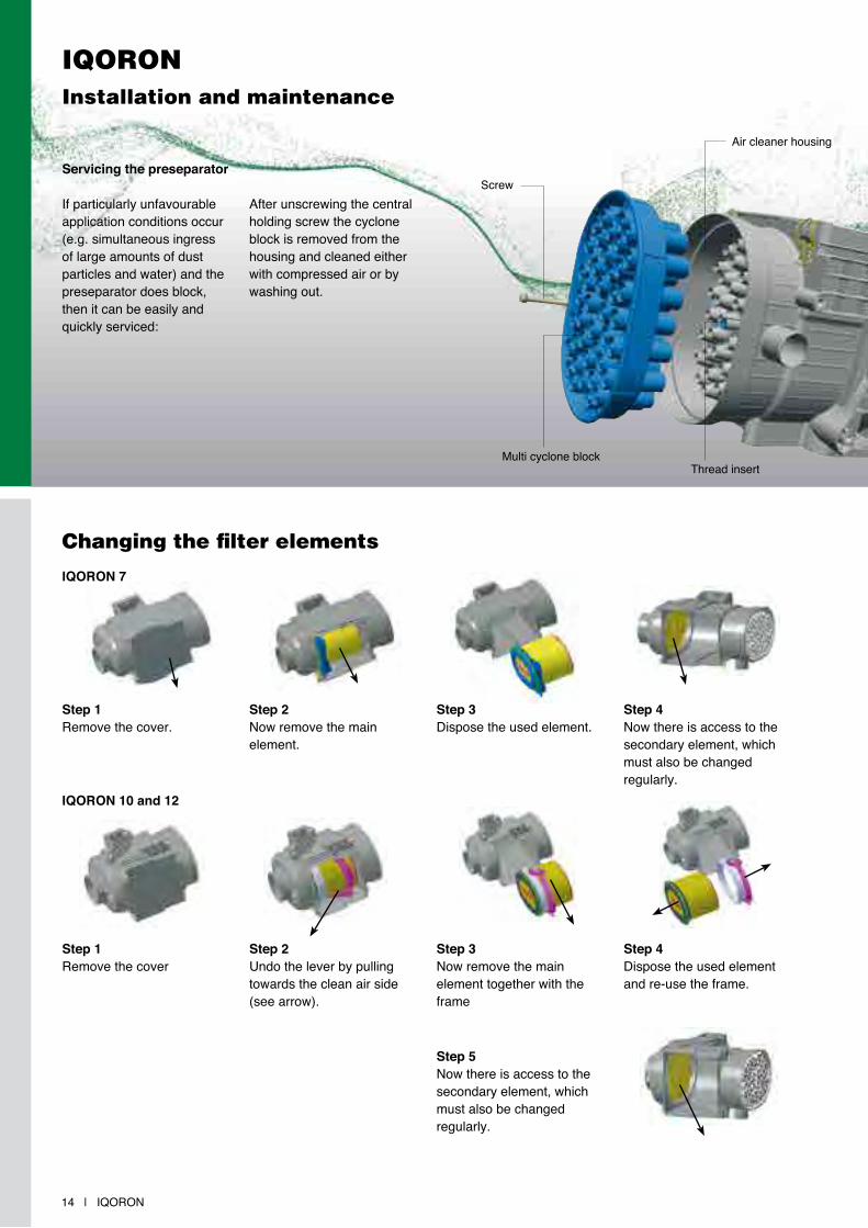
Servicing the preseparator
If particularly unfavourable application conditions occur (e.g. simultaneous ingress of large amounts of dust particles and water) and the preseparator does block, then it can be easily and quickly serviced:
After unscrewing the central holding screw the cyclone block is removed from the housing and cleaned either with compressed air or by washing out.
Changing the filter elements
Air cleaner housing
Screw
Multi cyclone block
Step 1remove the cover
Step 2Undo the lever by pulling towards the clean air side (see arrow).
Step 3now remove the main element together with the frame
Step 4Dispose the used element and re-use the frame.
Step 5now there is access to the secondary element, which must also be changed regularly.
IQORON 7
Step 1remove the cover.
Step 2now remove the main element.
Step 3Dispose the used element.
Step 4now there is access to the secondary element, which must also be changedregularly.
Thread insert
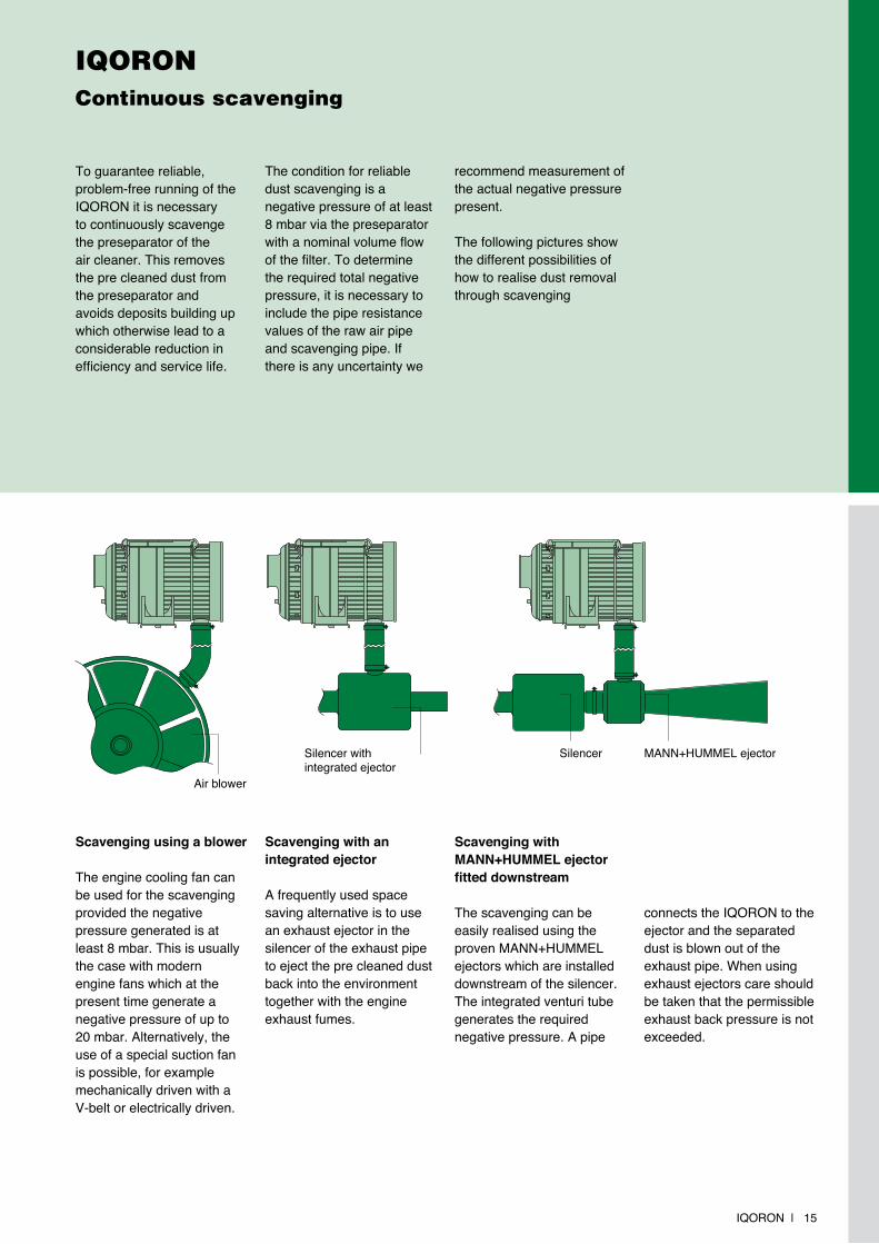
IqoroNContinuous scavenging
To guarantee reliable, problem-free running of the Iqoron it is necessary to continuously scavenge the preseparator of the air cleaner. This removes the pre cleaned dust from the preseparator and avoids deposits building up which otherwise lead to a considerable reduction in efficiency and service life.
Scavenging using a blower
The engine cooling fan can be used for the scavenging provided the negative pressure generated is at least 8 mbar. This is usually the case with modern engine fans which at the present time generate a negative pressure of up to 20 mbar. Alternatively, the use of a special suction fan is possible, for example mechanically driven with a V-belt or electrically driven.
Scavenging with an integrated ejector
A frequently used space saving alternative is to use an exhaust ejector in the silencer of the exhaust pipe to eject the pre cleaned dust back into the environment together with the engine exhaust fumes.
The condition for reliable dust scavenging is a negative pressure of at least 8 mbar via the preseparator with a nominal volume flow of the filter. To determine the required total negative pressure, it is necessary to include the pipe resistance values of the raw air pipe and scavenging pipe. If there is any uncertainty we
recommend measurement of the actual negative pressure present.
The following pictures show the different possibilities of how to realise dust removal through scavenging
Iqoron | 15
SilencerSilencer with integrated ejector
MAnn+HUMMEL ejector
Scavenging with MANN+HUMMEL ejector fitted downstream
The scavenging can be easily realised using the proven MAnn+HUMMEL ejectors which are installed downstream of the silencer. The integrated venturi tube generates the required negative pressure. A pipe
connects the Iqoron to the ejector and the separated dust is blown out of the exhaust pipe. When using exhaust ejectors care should be taken that the permissible exhaust back pressure is not exceeded.
Air blower
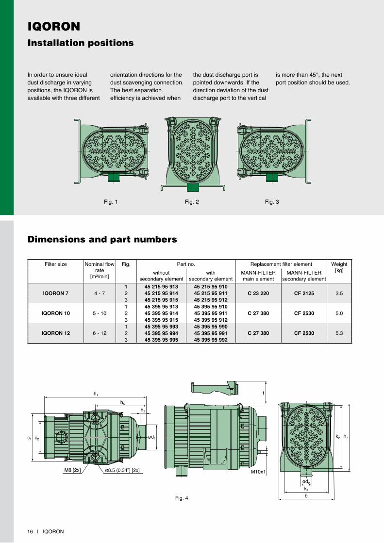
IqoroNInstallation positions
16 | Iqoron
Filter size nominal flow rate
[m³/min]
Fig. Part no. replacement filter element Weight[kg]without
secondary elementwith
secondary elementMAnn-FILTErmain element
MAnn-FILTErsecondary element
IQORON 7 4 - 71 45 215 95 913 45 215 95 910
C 23 220 CF 2125 3.52 45 215 95 914 45 215 95 9113 45 215 95 915 45 215 95 912
IQORON 10 5 - 101 45 395 95 913 45 395 95 910
C 27 380 CF 2530 5.02 45 395 95 914 45 395 95 9113 45 395 95 915 45 395 95 912
IQORON 12 6 - 121 45 395 95 993 45 395 95 990
C 27 380 CF 2530 5.32 45 395 95 994 45 395 95 9913 45 395 95 995 45 395 95 992
In order to ensure ideal dust discharge in varying positions, the Iqoron is available with three different
orientation directions for the dust scavenging connection. The best separation efficiency is achieved when
the dust discharge port is pointed downwards. If the direction deviation of the dust discharge port to the vertical
is more than 45°, the next port position should be used.
Fig. 1 Fig. 2 Fig. 3
Dimensions and part numbers
ød2
k1
h1
M8 [2x] ø8,5 (0,34”) [2x]
h5
h2
b
t
M10x1
k2 h7c2c1 ød1
Ø8.5 (0.34„) [2x]
Fig. 4

Iqoron | 17
IqoroNDimensions and part numbers
Filter size Fig. Dimensions in mm (Dimensions in inches)
b c1 c2 c3 c4 c5 c6 c7 c8 c9
IQORON 7 4 207.5(8.17)
173(6.81)
115.7(4.56) – – – – – – –
IQORON 10 5 236(9.29)
218(8.58)
155(6.10)
105.4(4.15)
233.4(9.19)
128.4(5.06)
98.4(3.87)
37.7(1.48)
123(4.84)
159.9(6.30)
IQORON 12 5 236(9.29)
218(8.58)
155(6.10)
105.4(4.15)
233.4(9.19)
128.4(5.06)
98.4(3.87)
37.7(1.48)
123(4.84)
159.9(6.30)
Filter size Fig. Dimensions in mm (Dimensions in inches)
d1 d2 h1 h2 h5 h6 h7 k1 k2 t
IQORON 7 4 89(3.50)
40(1.57)
368(14.49)
30(1.18)
183.5(7.22) – 240
(9.45)153
(6.02)226
(8.90)225.3(8.87)
IQORON 10 5 110(4.33)
40(1.57)
420(16.54)
30(1.18)
193.5(7.62)
135.2(5.32)
287(11.30)
189(7.44)
266(10.47)
263.9(10.39)
IQORON 12 5 110(4.33)
40(1.57)
425(16.73)
30(1.18)
193.5(7.62)
135.2(5.32)
287(11.30)
216(8.50)
293(11.54)
263.9(10.39)
Fig. 5
h6 h5
h1
h2
c2c3k1 c1
ød1h9
ø9 (3,5”) [2x]M8 [10x]
M10x1
t
k2
c5
c4
c6
c8
c7
c9
ød2
b
Ø9 (3.5„) [2x]
h6 h5
h1
h2
c2c3k1 c1
ød1h9
ø9 (3,5”) [2x]M8 [10x]
M10x1
t
k2
c5
c4
c6
c8
c7
c9
ød2
b
h7
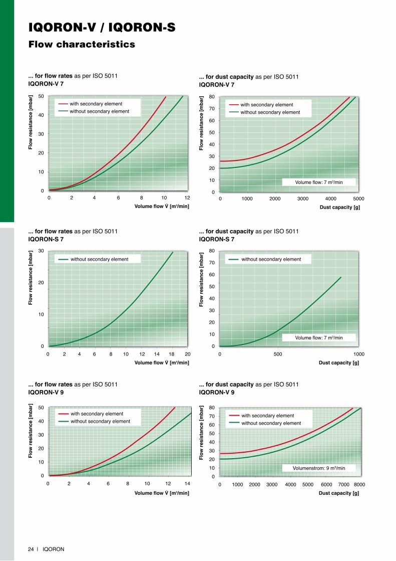
IqoroNFlow characteristics
... for flow rates as per ISo 5011 without secondary element
Flow
resi
stan
ce [m
bar]
Volume flow V̇ [m3/min]0 4 8 12 16 20
Iqoron 7Iqoron 10Iqoron 12
50
40
30
20
10
0
... for flow rates as per ISo 5011 without secondary element
Flow
resi
stan
ce [m
bar]
Volume flow V̇ [m3/min]0 4 8 12 16 20
50
40
30
20
10
0
Iqoron 7Iqoron 10Iqoron 12
... for dust capacity as per ISo 5011IQORON 7
Flow
resi
stan
ce [m
bar]
Dust capacity [g]0 1000 2000 3000 4000 5000 6000 7000
80
70
60
50
40
30
20
10
0
with secondary elementwithout secondary element
Volume flow: 7 m3/min
Flow
resi
stan
ce [m
bar]
80
70
60
50
40
30
20
10
0
... for dust capacity as per ISo 5011IQORON 10
Dust capacity [g]0 2000 4000 6000 8000 10000 12000 14000 16000
with secondary elementwithout secondary element
Volume flow: 10 m3/min
18 | Iqoron
80
70
60
50
40
30
20
10
0
... for dust capacity as per ISo 5011IQORON 12
Flow
resi
stan
ce [m
bar]
Dust capacity [g]0 2000 4000 6000 8000 10000 12000
with secondary elementwithout secondary element
Volume flow: 12 m3/min
Iqoron | 19
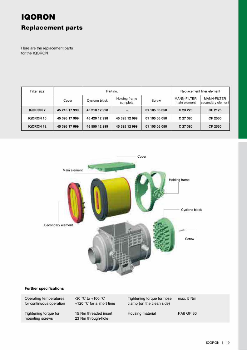
IqoroNreplacement parts
Here are the replacement parts for the Iqoron
Filter size Part no. replacement filter element
Cover Cyclone block Holding framecomplete Screw MAnn-FILTEr
main elementMAnn-FILTEr
secondary element
IQORON 7 45 215 17 999 45 210 12 998 – 01 105 06 050 C 23 220 CF 2125
IQORON 10 45 395 17 999 45 420 12 998 45 395 12 999 01 105 06 050 C 27 380 CF 2530
IQORON 12 45 395 17 999 45 550 12 999 45 395 12 999 01 105 06 050 C 27 380 CF 2530
Main element
Cover
Holding frame
Cyclone block
Screw
Secondary element
Further specifications
operating temperatures -30 °C to +100 °Cfor continuous operation +120 °C for a short time
Tightening torque for 15 nm threaded insertmounting screws 23 nm through-hole
Tightening torque for hose max. 5 nmclamp (on the clean side)
Housing material PA6 GF 30
20 | Iqoron
Filter housing
IqoroN-V / IqoroN-S
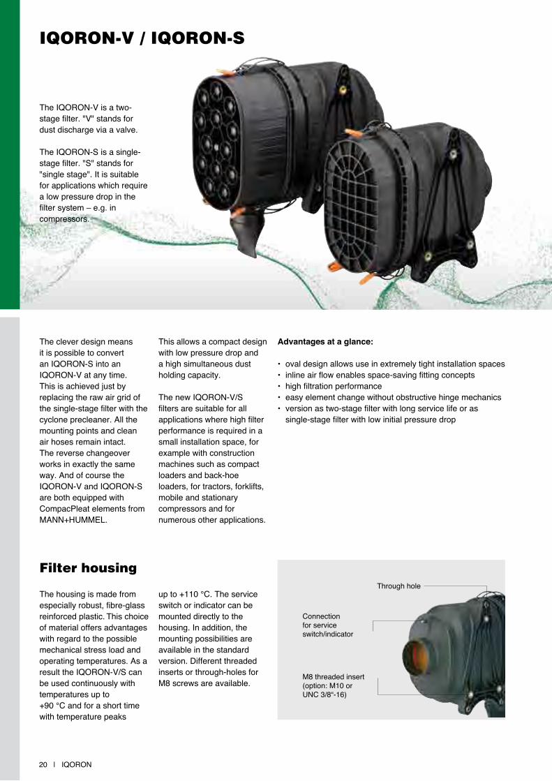
The Iqoron-V is a two-stage filter. "V" stands for dust discharge via a valve.
The Iqoron-S is a single-stage filter. "S" stands for "single stage". It is suitable for applications which require a low pressure drop in the filter system – e.g. in compressors.
The clever design means it is possible to convert an Iqoron-S into an Iqoron-V at any time. This is achieved just by replacing the raw air grid of the single-stage filter with the cyclone precleaner. All the mounting points and clean air hoses remain intact. The reverse changeover works in exactly the same way. And of course the Iqoron-V and Iqoron-S are both equipped with CompacPleat elements from MAnn+HUMMEL.
This allows a compact design with low pressure drop and a high simultaneous dust holding capacity.
The new Iqoron-V/S filters are suitable for all applications where high filter performance is required in a small installation space, for example with construction machines such as compact loaders and back-hoe loaders, for tractors, forklifts, mobile and stationary compressors and for numerous other applications.
Advantages at a glance:
• oval design allows use in extremely tight installation spaces• inline air flow enables space-saving fitting concepts• high filtration performance• easy element change without obstructive hinge mechanics• version as two-stage filter with long service life or as single-stage filter with low initial pressure drop
The housing is made from especially robust, fibre-glass reinforced plastic. This choice of material offers advantages with regard to the possible mechanical stress load and operating temperatures. As a result the Iqoron-V/S can be used continuously with temperatures up to +90 °C and for a short time with temperature peaks
up to +110 °C. The service switch or indicator can be mounted directly to the housing. In addition, the mounting possibilities are available in the standard version. Different threaded inserts or through-holes for M8 screws are available.
Through hole
Connection for service switch/indicator
M8 threaded insert(option: M10 orUnC 3/8“-16)
Iqoron | 21
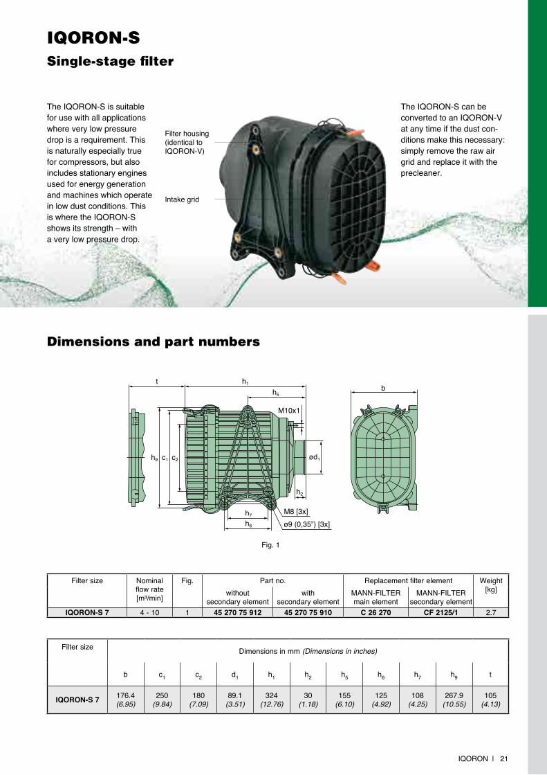
IqoroN-SSingle-stage filter
The Iqoron-S can be converted to an Iqoron-V at any time if the dust con-ditions make this necessary: simply remove the raw air grid and replace it with the precleaner.
The Iqoron-S is suitable for use with all applications where very low pressure drop is a requirement. This is naturally especially true for compressors, but also includes stationary engines used for energy generation and machines which operate in low dust conditions. This is where the Iqoron-S shows its strength – with a very low pressure drop.
Intake grid
Filter housing (identical to Iqoron-V)
Dimensions and part numbers
Filter size Dimensions in mm (Dimensions in inches)
b c1 c2 d1 h1 h2 h5 h6 h7 h9 t
IQORON-S 7 176.4(6.95)
250(9.84)
180(7.09)
89.1(3.51)
324(12.76)
30(1.18)
155(6.10)
125(4.92)
108(4.25)
267.9(10.55)
105(4.13)
h5
h7
h6
h2
h1t
c2c1h9
b
ø9 (0,35”) [3x]M8 [3x]
ød1
M10x1
Filter size nominal flow rate[m³/min]
Fig. Part no. replacement filter element Weight[kg]without
secondary elementwith
secondary elementMAnn-FILTErmain element
MAnn-FILTErsecondary element
IQORON-S 7 4 - 10 1 45 270 75 912 45 270 75 910 C 26 270 CF 2125/1 2.7
Fig. 1
IqoroN-VTwo-stage filter
22 | Iqoron
Filter size nominal flow rate[m³/min]
Fig. Part no. replacement filter element Weight[kg]without
secondary elementwith
secondary elementMAnn-FILTErmain element
MAnn-FILTErsecondary element
IQORON-V 7 4 - 7 1 45 270 95 912 45 270 95 910 C 26 270 CF 2125/1 3.12 45 270 95 913 45 270 95 911
IQORON-V 9 5 - 9
3 45 402 95 914 45 402 95 910*
C 30 400/1 CF 2631 4.84 45 402 95 915 45 402 95 9113 45 402 95 916 45 402 95 9124 45 402 95 917 45 402 95 913**
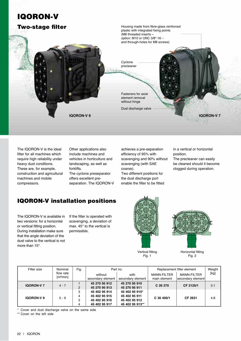
The Iqoron-V is available in two versions: for a horizontal or vertical fitting position. During installation make sure that the angle deviation of the dust valve to the vertical is not more than 15°.
The Iqoron-V is the ideal filter for all machines which require high reliability under heavy dust conditions. These are, for example, construction and agricultural machines and mobile compressors.
If the filter is operated with scavenging, a deviation of max. 45° to the vertical is permissible.
other applications also include machines and vehicles in horticulture and landscaping, as well as forklifts.The cyclone preseparator offers excellent pre-separation. The Iqoron-V
achieves a pre-separation efficiency of 95% with scavenging and 90% without scavenging (with SAE coarse).Two different positions for the dust discharge port enable the filter to be fitted
in a vertical or horizontal position.The precleaner can easily be cleaned should it become clogged during operation.
Vertical fittingFig. 1
Horizontal fitting Fig. 2
IqoroN-V installation positions
Cyclone precleaner
Fasteners for axial element removal without hinge
Housing made from fibre-glass reinforced plastic with integrated fixing points (M8 threaded inserts – option: M10 or UnC 3/8“-16 – and through-holes for M8 screws)
Dust discharge valve
IQORON-V 9 IQORON-V 7
* Cover and dust discharge valve on the same side** Cover on the left side
Iqoron | 23
IqoroN-VDimensions and part numbers
Filter size Dimensions in mm (Dimensions in inches)
b c1 c2 c7 c8 c9 d1 h1 h2
IQORON-V 7* 176.4(6.95)
250(9.84)
180(7.09) – – – 89.1
(3.51)378
(14.88)30
(1.18)
IQORON-V 9 185(7.28)
130(5.12) – 63
(2.84)145
(5.71)100
(3.94)102
(4.02)418.8
(16.49)34
(1.34)
Filter size Dimensions in mm (Dimensions in inches)
h5 h6 h7 h8 h9 k1 k2 t
Fig. 3 Fig. 4
IQORON-V 7* 155(6.10)
125(4.92)
108(4.25)
86.1(3.39)
88.5(3.48)
268.8(10.58)
153(6.02)
245.4(9.66)
50(1.97)
IQORON-V 9 75.3(2.97)
205(8.07) – 91.1
(3.59)91.5
(3.60)314.9
(12.40)157.2(6.19)
289.7(11.41)
210.1(8.27)
h6
h2
h1
h6h5
c1
h8
k1b
M10x1 [2x]
M8 [12x]
t
h9 ød1
h8
k2c8
c7
c9
M6 [4x]
h6
h2
h1
h6h5
c1
h8
k1b
M10x1 [2x]
M8 [12x]
t
h9 ød1
h8
k2c8
c7
c9
M6 [4x]Fig. 3
Fig. 4
* see Fig. 1, page 21
IqoroN-V / IqoroN-SFlow characteristics
24 | Iqoron
... for flow rates as per ISo 5011 IQORON-V 7
Flow
resi
stan
ce [m
bar]
Volume flow V̇ [m3/min]0 2 4 6 8 10 12
50
40
30
20
10
0
with secondary elementwithout secondary element
... for flow rates as per ISo 5011 IQORON-S 7
Flow
resi
stan
ce [m
bar]
Volume flow V̇ [m3/min]0 2 4 6 8 10 12 14 18 20
30
20
10
0
without secondary element
... for dust capacity as per ISo 5011IQORON-V 7
Flow
resi
stan
ce [m
bar]
Dust capacity [g]0 1000 2000 3000 4000 5000
with secondary elementwithout secondary element
80
70
60
50
40
30
20
10
0Fl
ow re
sist
ance
[mba
r]
80
70
60
50
40
30
20
10
0
... for dust capacity as per ISo 5011IQORON-S 7
Dust capacity [g]0 500 1000
without secondary element
Volume flow: 7 m3/min
Volume flow: 7 m3/min
... for flow rates as per ISo 5011 IQORON-V 9
Flow
resi
stan
ce [m
bar]
Volume flow V̇ [m3/min]
0 2 4 6 8 10 12 14
50
40
30
20
10
0
with secondary elementwithout secondary element
Flow
resi
stan
ce [m
bar] 80
70605040302010
0
... for dust capacity as per ISo 5011IQORON-V 9
Dust capacity [g]0 1000 2000 3000 4000 5000 6000 7000 8000
Volumenstrom: 9 m3/min
with secondary elementwithout secondary element
Iqoron | 25
IqoroN-V / IqoroN-SSpare parts
Filter size Part no. replacement filter element
Cover Dust discharge valve MAnn-FILTErmain element
MAnn-FILTErsecondary element
IQORON-V 9 45 402 17 929 39 000 40 731 C 30 400/1 CF 2631
Filter size Part no. replacement filter element
Fig.(see
page 22)
Cyclone block Dust discharge valve
Grid Foam MAnn-FILTErmain element
MAnn-FILTErsecondary element
IQORON-S 7 1 – – 45 280 12 972 45 270 04 100
C 26 270 CF 2125/1IQORON-V 7
1 45 280 47 98239 000 40 731 – –
2 45 280 47 962
Main element
Main element
GridDust discharge valve
Dust discharge valve
Cyclone block
Secondary element
IQORON-V 7
IQORON-S 7
IQORON-V 9
Cover
Further specifications
operating temperatures -V 7 / -S 7: -30 °C to +90 °C for continuous operation -V 9: -40 °C to +100 °C
-V 7 / -S 7: +110 °C for a short time -V 9: +120 °C for a short time
Tightening torque for 15 nm threaded insertmounting screws 23 nm through-hole
Tightening torque for hose max. 5 nmclamp (on the clean side)
Housing material PA6 GF 30 Cr(VI)-free

26 | Iqoron
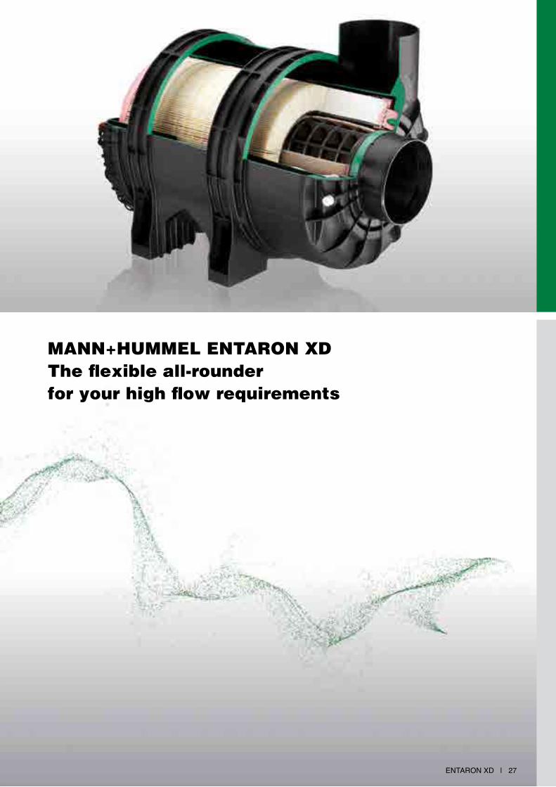
Entaron XD | 27
MANN+HUMMEL ENtAroN XD the flexible all-rounder for your high flow requirements
28 | Entaron XD
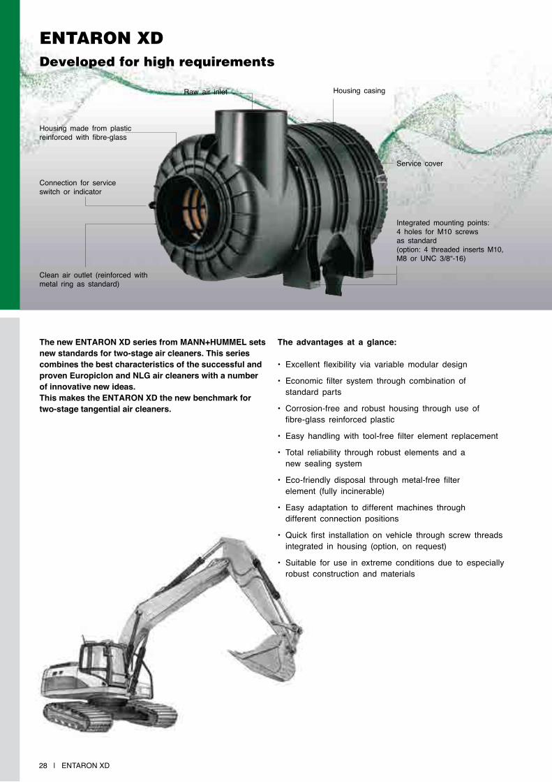
ENtAroN XD Developed for high requirements
The new ENTARON XD series from MANN+HUMMEL sets new standards for two-stage air cleaners. This series combines the best characteristics of the successful and proven Europiclon and NLG air cleaners with a number of innovative new ideas. This makes the ENTARON XD the new benchmark for two-stage tangential air cleaners.
The advantages at a glance:
• Excellent flexibility via variable modular design
• Economic filter system through combination of standard parts
• Corrosion-free and robust housing through use of fibre-glass reinforced plastic
• Easy handling with tool-free filter element replacement
• total reliability through robust elements and a new sealing system
• Eco-friendly disposal through metal-free filter element (fully incinerable)
• Easy adaptation to different machines through different connection positions
• Quick first installation on vehicle through screw threads integrated in housing (option, on request)
• Suitable for use in extreme conditions due to especially robust construction and materials
Connection for service switch or indicator
Housing made from plastic reinforced with fibre-glass
raw air inlet Housing casing
Service cover
Integrated mounting points: 4 holes for M10 screws as standard (option: 4 threaded inserts M10, M8 or UnC 3/8“-16)
Clean air outlet (reinforced with metal ring as standard)
Entaron XD | 29
robust housing
the housing of the new Entaron XD is reinforced with FEM-designed strengthening ribs and made from plastic reinforced with fibre-glass. this means the filter is able to handle extreme physical conditions and at the same time is resistant to corrosion.
the filter construction consists of three elements with the main housing attached to the connections using a special welding process. this welding ensures a ro-bust and reliable joint and at the same time enables unlimited possible orienta-tions of the connection to the integrated bracket. this achieves an extremely high flexibility and enables adaptation of the filter to almost all installation situations.the clean air outlet is also reinforced as standard with a metal ring which allows a tightening torque on the hose clamps of up to 5 nm.
naturally the standard ver-sion also has an integrated connection port for a service switch or indicator.
the high pre-separation efficiency of over 85 % makes the new Entaron XD ideal for applications with heavy dust loads. this value of 85% sets the standard for its size filter class with comparable competitor products only able to achieve a much lower value. this high pre-separation efficiency also eliminates the need for an additional external preseparator.
Clever details
Color-coded fasteners simplify handling and are easy to understand even when visibility conditions are unfavorable.
the fasteners can also be locked using special snap-in noses so they are no longer in the way when removing or attaching the cover. another user-friendly and clever de-tail from Mann+HUMMEL.
Fasteners (positioned according to customer requirements)
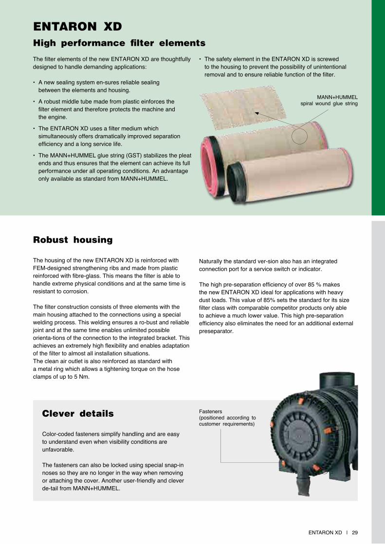
the filter elements of the new Entaron XD are thoughtfully designed to handle demanding applications:
• a new sealing system en-sures reliable sealing between the elements and housing.
• a robust middle tube made from plastic einforces the filter element and therefore protects the machine and the engine.
• the Entaron XD uses a filter medium which simultaneously offers dramatically improved separation efficiency and a long service life.
• the Mann+HUMMEL glue string (GSt) stabilizes the pleat ends and thus ensures that the element can achieve its full performance under all operating conditions. an advantage only available as standard from Mann+HUMMEL.
• the safety element in the Entaron XD is screwed to the housing to prevent the possibility of unintentional removal and to ensure reliable function of the filter.
Mann+HUMMELspiral wound glue string
ENtAroN XD High performance filter elements
ENtAroN XD Dimensions and part numbers
30 | Entaron XD
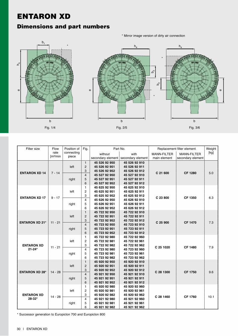
Fig. 1/4
* Mirror image version of dirty air connection
* Successor generation to Europiclon 700 and Europiclon 800
Fig. 2/5 Fig. 3/6
Filter size Flow rate
[m³/min
Position of connecting
piece
Fig. Part no. replacement filter element Weight[kg]without
secondary elementwith
secondary elementMann-FILtErmain element
Mann-FILtErsecondary element
ENTARON XD 14 7 - 14
left1 45 526 92 950 45 526 92 910
C 21 600 CF 1280 5.0
2 45 526 92 951 45 526 92 9113 45 526 92 952 45 526 92 912
right4 45 527 92 950 45 527 92 9105 45 527 92 951 45 527 92 9116 45 527 92 952 45 527 92 912
ENTARON XD 17 9 - 17
left1 45 625 92 950 45 625 92 910
C 23 800 CF 1350 6.3
2 45 625 92 951 45 625 92 9113 45 625 92 952 45 625 92 912
right4 45 626 92 950 45 626 92 9105 45 626 92 951 45 626 92 9116 45 626 92 952 45 626 92 912
ENTARON XD 21* 11 - 21
left1 45 722 92 950 45 722 92 910
C 25 900 CF 1470 7.3
2 45 722 92 951 45 722 92 9113 45 722 92 952 45 722 92 912
right4 45 723 92 950 45 723 92 9105 45 723 92 951 45 723 92 9116 45 723 92 952 45 723 92 912
ENTARON XD21-24* 11 - 21
left1 45 722 92 980 45 722 92 960
C 25 1020 CF 1480 7.9
2 45 722 92 981 45 722 92 9613 45 722 92 982 45 722 92 962
right4 45 723 92 980 45 723 92 9605 45 723 92 981 45 723 92 9616 45 723 92 982 45 723 92 962
ENTARON XD 28* 14 - 28
left1 45 920 92 950 45 920 92 910
C 28 1300 CF 1750 9.6
2 45 920 92 951 45 920 92 9113 45 920 92 952 45 920 92 912
right4 45 921 92 950 45 921 92 9105 45 921 92 951 45 921 92 9116 45 921 92 952 45 921 92 912
ENTARON XD28-32* 14 - 28
left1 45 920 92 980 45 920 92 960
C 28 1460 CF 1760 10.1
2 45 920 92 981 45 920 92 9613 45 920 92 982 45 920 92 962
right4 45 921 92 980 45 921 92 9605 45 921 92 981 45 921 92 9616 45 921 92 982 45 921 92 962
*
*
*
h 4
b b b
h4
b 2
e
b1
e
h4
e
b 2
Entaron XD | 31
ENtAroN XD Dimensions and part numbers
h1 th2
h5 h6
h3 ø d1
ø d 2
ø d 3
c 1c 2
h 7
M10 (4x)M10x1 ø 11 (0.43) (4x)
Filter size Dimensions in mm (Dimensions in inches)
b b1 c1 c2 d1 d2 d3 e h1 h2 h3 h4 h5 h6 h7 t
ENTARONXD 14
300(11.82)
79(3.11)
263.3(10.37)
175.3(6.90)
130(5.20)
110(4.33)
305.7(12.04)
159.7(6.29)
422.9(16.65)
45(1.77)
72.8(2.87)
186.5(7.34)
218.4(8.60)
136.8(5.39)
85.8(3.38)
362(14.25)
ENTARONXD 17
328.2(12.92)
90.1(3.55)
291.8(11.92)
203.8(8.03)
130(5.20)
130(5.20)
335.1(13.19)
173.7(6.84)
474.8(18.70)
45(1.77)
80.3(3.16)
198(7.80)
235.8(9.29)
169.9(6.69)
90.4(3.56)
408(16.06)
ENTARONXD 21
357.8(14.09)
92(3.62)
320(12.60)
232(9.13)
150(5.91)
150(5.91)
368.9(14.52)
193(7.60)
491(19.33)
45(1.77)
90(3.54)
215(8.46)
254(10)
167(6.58)
82.1(3.23)
426(16.77)
ENTARONXD 21-24
357.8(14.09)
92(3.62)
320(12.60)
232(9.13)
150(5.91)
150(5.91)
368.9(14.52)
193(7.60)
546(21.50)
45(1.77)
90(3.54)
215(8.46)
254(10)
221.8(8.73)
82.1(3.23)
480(18.90)
ENTARONXD 28
388(12.28)
96(3.78)
354(13.94)
266(10.47)
180(7.09)
180(7.09)
398(15.63)
208(8.19)
572(22.48)
45(1.77)
105(4.13)
245(9.65)
283(11.14)
220(8.66)
80.7(3.18)
505(19.88)
ENTARONXD 28-32
388(12.28)
96(3.78)
354(13.54)
266(10.47)
180(7.09)
180(7.09)
398(15.63)
208(8.19)
638(25.12)
45(1.77)
105(4.13)
245(9.65)
283(11.14)
285(11.22)
80.7(3.18)
573(22.56)
(option – on request)

ENtAroN XD Flow characteristics
32 | Entaron XD
Further specificationsoperating temperatures -30 °C to +90 °C Continuous operation +110 °C short-term
tightening torque 15 nm threaded insertMounting screws 23 nm through-hole
5 10 2015
... for flow rates according ISo 5011ENTARON XD 14
Flow
res
ista
nce
[mba
r]
Flow rate V̇ [m3/min]0 5 10 15 20 25
50
40
30
20
10
0
with secondary elementwithout secondary element
... for dust capacity according ISo 5011ENTARON XD 14
Flow
res
ista
nce
[mba
r]
Dust capacity [g]0 2000 4000 6000 8000 10000 12000 14000
80
70
60
50
40
30
20
10
0
with secondary elementwithout secondary element
... for flow rates according ISo 5011ENTARON XD 17
Flow
res
ista
nce
[mba
r]
Flow rate V̇ [m3/min]0 5 10 15 20 25 30
50
40
30
20
10
0
with secondary elementwithout secondary element
80
70
60
50
40
30
20
10
0
... for dust capacity according ISo 5011ENTARON XD 17
Flow
res
ista
nce
[mba
r]
Dust capacity [g]0 2000 4000 6000 8000 10000 12000 14000 16000 18000
with secondary elementwithout secondary element
... for flow rates according ISo 5011ENTARON XD 21
Flow
res
ista
nce
[mba
r]
Flow rate V̇ [m3/min]0 5 10 15 20 25 30 35
50
40
30
20
10
0
with secondary elementwithout secondary element
80
70
60
50
40
30
20
10
0
... for dust capacity according ISo 5011ENTARON XD 21
Flow
res
ista
nce
[mba
r]
Dust capacity [g]0 4000 8000 12000 16000 20000
with secondary elementwithout secondary element
Entaron XD | 33
ENtAroN XD Flow characteristics
Further specificationstightening torque for max. 5 nmhose clamp (on clean side)
Housing material PP GF 30 / Cr(VI)-free Connection dimension of Diameter 54 mmdust discharge
... for flow rates according ISo 5011ENTARON XD 21-24
Flow
res
ista
nce
[mba
r]
Flow rate V̇ [m3/min]0 5 10 15 20 25 30 35
50
40
30
20
10
0
with secondary elementwithout secondary element
... for flow rates according ISo 5011ENTARON XD 28
Flow
res
ista
nce
[mba
r]
Flow rate V̇ [m3/min]0 5 10 15 20 25 30 35 40 45
50
40
30
20
10
0
with secondary elementwithout secondary element
Flow
res
ista
nce
[mba
r]
... for dust capacity according ISo 5011ENTARON XD 21-24
Flow
res
ista
nce
[mba
r]Dust capacity [g]
0 4000 8000 12000 16000 20000 24000
80
70
60
50
40
30
20
10
0
with secondary elementwithout secondary element
80
70
60
50
40
30
20
10
0
... for dust capacity according ISo 5011ENTARON XD 28
Dust capacity [g]0 4000 8000 12000 16000 20000 24000
with secondary elementwithout secondary element
... for flow rates according ISo 5011ENTARON XD 28-32
Flow
res
ista
nce
[mba
r]
Flow rate V̇ [m3/min]0 5 10 15 20 25 30 35 40 45
50
40
30
20
10
0
with secondary elementwithout secondary element
Flow
res
ista
nce
[mba
r] 80
70
60
50
40
30
20
10
0
... for dust capacity according ISo 5011ENTARON XD 28-32
Dust capacity [g]0 5000 10000 15000 20000 25000 30000 35000
with secondary elementwithout secondary element

ENtAroN XD Accessories
34 | Entaron XD
the following accessories are suitable for use with the Entaron XD.
Filter size rain cap (page 100/101) Straight connectors (page 104) 90° elbow (page 103)Form a Form B Fig. 1 Fig. 2 Fig. 1 Fig. 2
ENTARON XD 14 39 160 67 910 39 160 67 020 39 600 27 999 39 600 27 979 39 600 25 999 39 600 25 979ENTARON XD 17 39 160 67 910 39 160 67 020 39 700 27 999 39 700 27 979 39 700 25 999 39 700 25 979ENTARON XD 21 39 190 67 910 45 880 67 100 39 800 27 999 39 800 27 979 39 800 25 999 39 800 25 979ENTARON XD 21-24 39 190 67 910 45 880 67 100 39 800 27 999 39 800 27 979 39 800 25 999 39 800 25 979ENTARON XD 28 39 220 67 910 39 220 67 100 39 930 27 999 39 930 27 979 39 930 25 999 39 930 25 979ENTARON XD 28-32 39 220 67 910 39 220 67 100 39 930 27 999 39 930 27 979 39 930 25 999 39 930 25 979
Filter size Part no. replacement filter element
Cover Dust discharge valve Mann-FILtErmain element
Mann-FILtErsecondary element
ENTARON XD 14 45 526 17 909 39 000 40 731 C 21 600 CF 1280ENTARON XD 17 45 625 17 909 39 000 40 731 C 23 800 CF 1350ENTARON XD 21 45 722 17 909 39 000 40 731 C 25 900 CF 1470ENTARON XD 21-24 45 722 17 919 39 000 40 731 C 25 1020 CF 1480ENTARON XD 28 45 920 17 909 39 000 40 731 C 28 1300 CF 1750ENTARON XD 28-32 45 920 17 919 39 000 40 731 C 28 1460 CF 1760
the following is a list of suitable spare parts for the Entaron XD.
Spare parts
Main elementCover
Dust discharge valve
Secondary element
EUROPICLON | 35
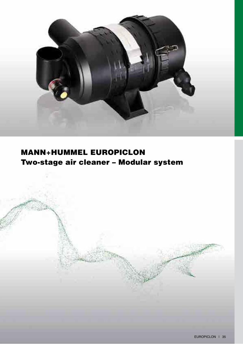
MANN+HUMMEL EUROPICLONTwo-stage air cleaner – Modular system

36 | EUROPICLON
EUROPICLON The flexible allrounder
The Europiclon from MANN+HUMMEL is characterised by its high dust capacity and low pressure drop.
These characteristics have made the Europiclon the tried and tested air cleaner for all machines and equipment used in conditions with medium to heavy dust loads. These include construction and agricultural machines, mobile compressors and harvesting machines.
Advantages at a glance:
• long service life through integrated pre-separation
• highly economical through modular system
• extensive range of accessories
• corrosion free housing in impact resistant plastic
• easy element change without tools
• highest operational reliability through elements with proven radial seal
• metal-free filter elements are easily disposed of by incineration and therefore are environmentally friendly with inexpensive disposal
• easy adaptation to other equipment with a flexible bracket system
• patented filter elements
FrEisTELLEr
EUROPICLON | 37
Housing
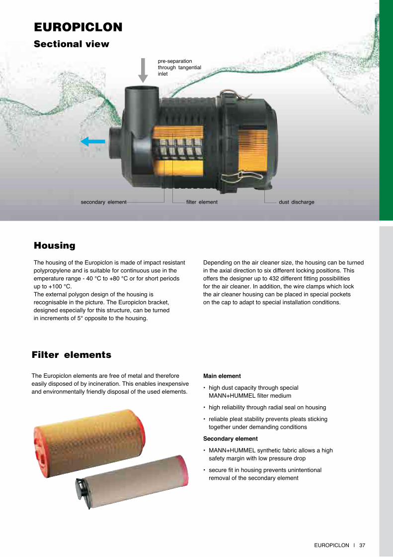
The housing of the Europiclon is made of impact resistant polypropylene and is suitable for continuous use in the emperature range - 40 °C to +80 °C or for short periods up to +100 °C.The external polygon design of the housing is recognisable in the picture. The Europiclon bracket, designed especially for this structure, can be turned in increments of 5° opposite to the housing.
Depending on the air cleaner size, the housing can be turned in the axial direction to six different locking positions. This offers the designer up to 432 different fitting possibilities for the air cleaner. In addition, the wire clamps which lock the air cleaner housing can be placed in special pockets on the cap to adapt to special installation conditions.
EUROPICLONSectional view
Filter elements
The Europiclon elements are free of metal and therefore easily disposed of by incineration. This enables inexpensive and environmentally friendly disposal of the used elements.
Main element
• high dust capacity through special MANN+HUMMEL filter medium
• high reliability through radial seal on housing
• reliable pleat stability prevents pleats sticking together under demanding conditions
secondary element
• MANN+HUMMEL synthetic fabric allows a high safety margin with low pressure drop
• secure fit in housing prevents unintentional removal of the secondary element
pre-separation through tangential inlet
secondary element filter element dust discharge
38 | EUROPICLON
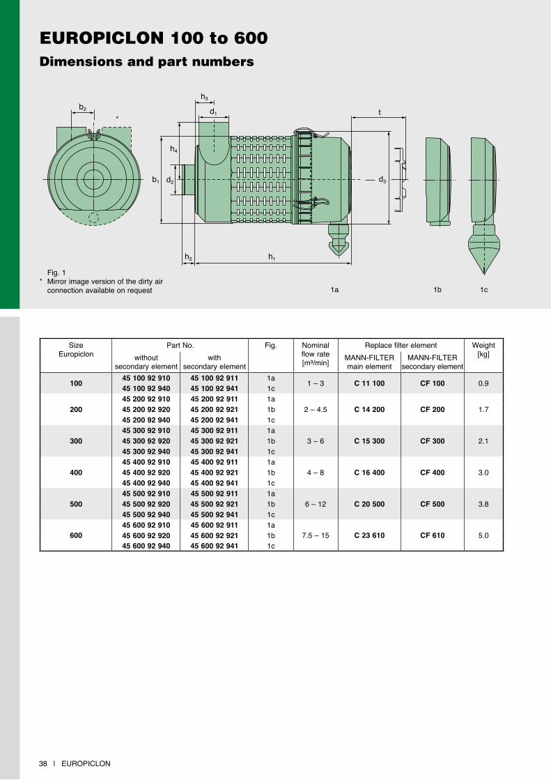
SizeEuropiclon
Part No. Fig. Nominal flow rate[m³/min]
Replace filter element Weight[kg]without
secondary elementwith
secondary elementMANN-FILTERmain element
MANN-FILTERsecondary element
100 45 100 92 910 45 100 92 911 1a 1 – 3 C 11 100 CF 100 0.945 100 92 940 45 100 92 941 1c
20045 200 92 910 45 200 92 911 1a
2 – 4.5 C 14 200 CF 200 1.745 200 92 920 45 200 92 921 1b45 200 92 940 45 200 92 941 1c
30045 300 92 910 45 300 92 911 1a
3 – 6 C 15 300 CF 300 2.145 300 92 920 45 300 92 921 1b45 300 92 940 45 300 92 941 1c
40045 400 92 910 45 400 92 911 1a
4 – 8 C 16 400 CF 400 3.045 400 92 920 45 400 92 921 1b45 400 92 940 45 400 92 941 1c
50045 500 92 910 45 500 92 911 1a
6 – 12 C 20 500 CF 500 3.845 500 92 920 45 500 92 921 1b45 500 92 940 45 500 92 941 1c
60045 600 92 910 45 600 92 911 1a
7.5 – 15 C 23 610 CF 610 5.045 600 92 920 45 600 92 921 1b45 600 92 940 45 600 92 941 1c
EUROPICLON 100 to 600 Dimensions and part numbers
b2
b1 d2
d1
h4
h3
h2 h1
d3
t
1a 1c1b
Fig. 1* Mirror image version of the dirty air connection available on request
*
EUROPICLON | 39
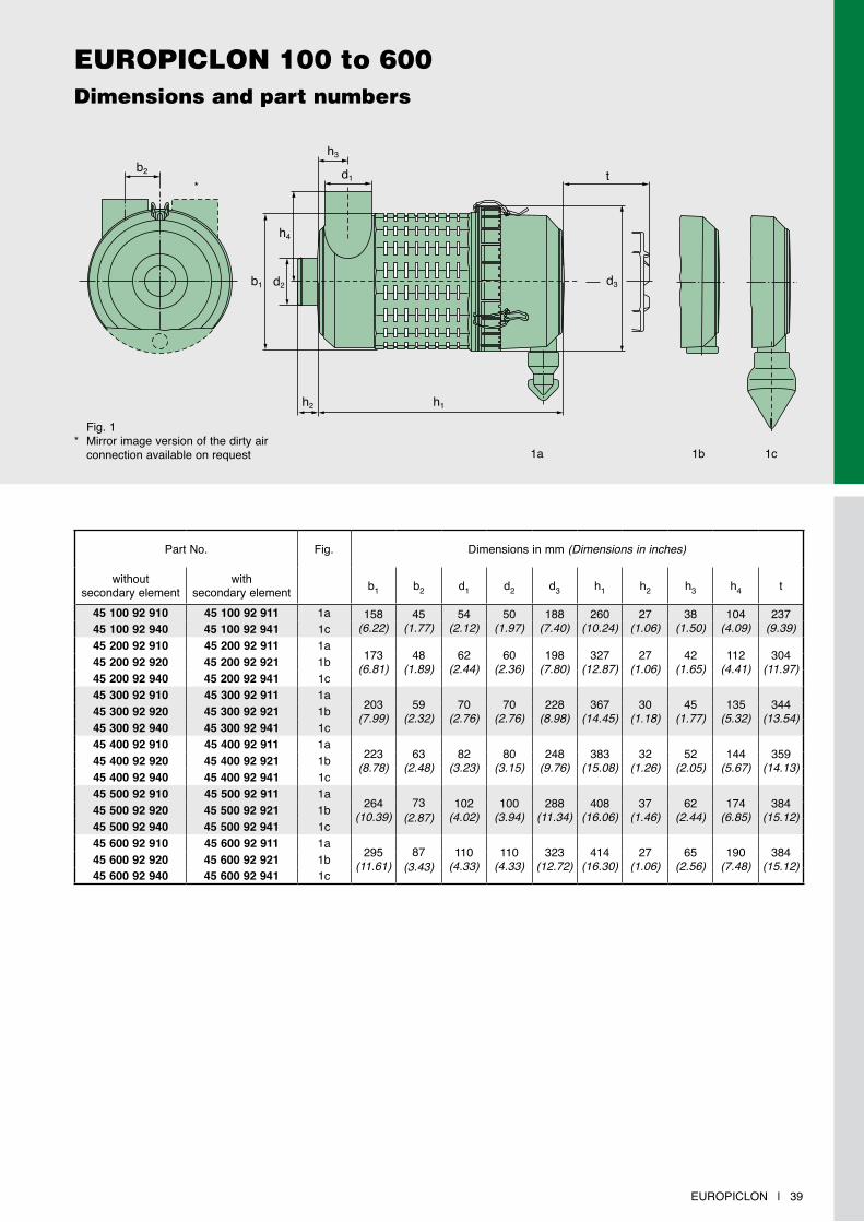
EUROPICLON 100 to 600 Dimensions and part numbers
b2
b1 d2
d1
h4
h3
h2 h1
d3
t
1a 1c1b
Fig. 1* Mirror image version of the dirty air connection available on request
Part No. Fig. Dimensions in mm (Dimensions in inches)
without secondary element
with secondary element b1 b2 d1 d2 d3 h1 h2 h3 h4 t
45 100 92 910 45 100 92 911 1a 158(6.22)
45(1.77)
54(2.12)
50(1.97)
188(7.40)
260(10.24)
27(1.06)
38(1.50)
104(4.09)
237(9.39)45 100 92 940 45 100 92 941 1c
45 200 92 910 45 200 92 911 1a173
(6.81)48
(1.89)62
(2.44)60
(2.36)198
(7.80)327
(12.87)27
(1.06)42
(1.65)112
(4.41)304
(11.97)45 200 92 920 45 200 92 921 1b45 200 92 940 45 200 92 941 1c45 300 92 910 45 300 92 911 1a
203(7.99)
59(2.32)
70(2.76)
70(2.76)
228(8.98)
367(14.45)
30(1.18)
45(1.77)
135(5.32)
344(13.54)45 300 92 920 45 300 92 921 1b
45 300 92 940 45 300 92 941 1c45 400 92 910 45 400 92 911 1a
223(8.78)
63(2.48)
82(3.23)
80(3.15)
248(9.76)
383(15.08)
32(1.26)
52(2.05)
144(5.67)
359(14.13)45 400 92 920 45 400 92 921 1b
45 400 92 940 45 400 92 941 1c45 500 92 910 45 500 92 911 1a
264(10.39)
73(2.87)
102(4.02)
100(3.94)
288(11.34)
408(16.06)
37(1.46)
62(2.44)
174(6.85)
384(15.12)45 500 92 920 45 500 92 921 1b
45 500 92 940 45 500 92 941 1c45 600 92 910 45 600 92 911 1a
295(11.61)
87(3.43)
110(4.33)
110(4.33)
323(12.72)
414(16.30)
27(1.06)
65(2.56)
190(7.48)
384(15.12)45 600 92 920 45 600 92 921 1b
45 600 92 940 45 600 92 941 1c
*
EUROPICLON 100 to 600Flow characteristics without secondary element
40 | EUROPICLON
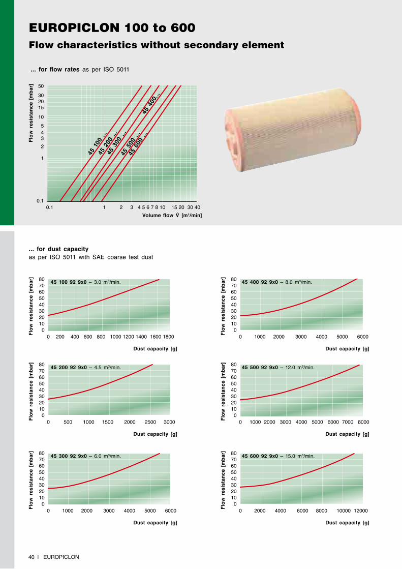
... for flow rates as per ISO 5011
Flow
res
ista
nce
[mba
r]
Volume flow V̇ [m3/min]
45 1
00 ..
.45
200
...
45 3
00 ..
.
45 4
00...
45 5
00 ..
.45
600
...
0.1 1 2 3 4 5 6 7 8 10 15 20 30 40
50
30 2015
105432
1
0.1
... for dust capacity as per ISO 5011 with SAE coarse test dust
Flow
res
ista
nce
[mba
r]
Dust capacity [g]
0 200 400 600 800 1000 1200 1400 1600 1800
80706050403020100
45 100 92 9x0 – 3.0 m3/min.
Flow
res
ista
nce
[mba
r]
Dust capacity [g]
0 500 1000 1500 2000 2500 3000
80706050403020100
45 200 92 9x0 – 4.5 m3/min.
Flow
res
ista
nce
[mba
r]
Dust capacity [g]
0 1000 2000 3000 4000 5000 6000
80706050403020100
45 300 92 9x0 – 6.0 m3/min.
Flow
res
ista
nce
[mba
r]
Dust capacity [g]
0 1000 2000 3000 4000 5000 6000
8070605040302010
0
45 400 92 9x0 – 8.0 m3/min.
Flow
res
ista
nce
[mba
r]
Dust capacity [g]
0 1000 2000 3000 4000 5000 6000 7000 8000
8070605040302010
0
45 500 92 9x0 – 12.0 m3/min.
Flow
res
ista
nce
[mba
r]
Dust capacity [g]
0 2000 4000 6000 8000 10000 12000
8070605040302010
0
45 600 92 9x0 – 15.0 m3/min.
EUROPICLON | 41
EUROPICLON 100 to 600Flow characteristics with secondary element
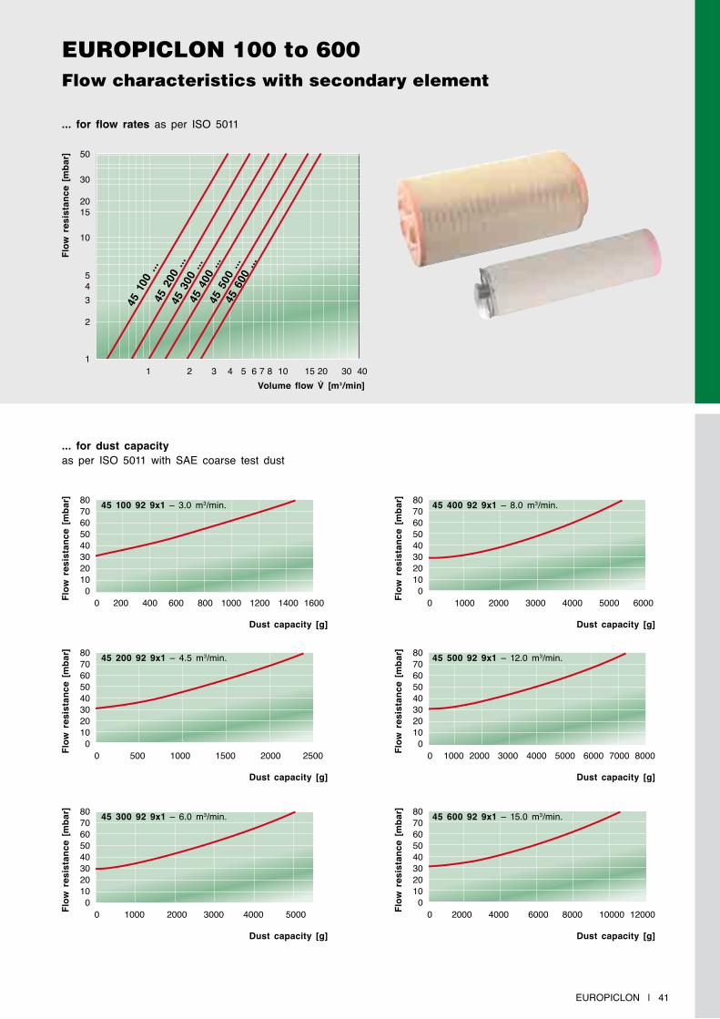
... for flow rates as per ISO 5011
Flow
res
ista
nce
[mba
r]
Volume flow V̇ [m3/min]
45 1
00 ..
.45
200
...
45 3
00 ..
.45
400
...
45 5
00 ..
.45
600
...
1 2 3 4 5 6 7 8 10 15 20 30 40
50
30
2015
10
543
2
1
... for dust capacity as per ISO 5011 with SAE coarse test dust
Flow
res
ista
nce
[mba
r]
Dust capacity [g]
0 200 400 600 800 1000 1200 1400 1600
80706050403020100
45 100 92 9x1 – 3.0 m3/min.
Flow
res
ista
nce
[mba
r]
Dust capacity [g]
0 500 1000 1500 2000 2500
80706050403020100
45 200 92 9x1 – 4.5 m3/min.
Flow
res
ista
nce
[mba
r]
Dust capacity [g]
0 1000 2000 3000 4000 5000
80706050403020100
45 300 92 9x1 – 6.0 m3/min.
Flow
res
ista
nce
[mba
r]
Dust capacity [g]
0 1000 2000 3000 4000 5000 6000
8070605040302010
0
45 400 92 9x1 – 8.0 m3/min.
Flow
res
ista
nce
[mba
r]
Dust capacity [g]
0 1000 2000 3000 4000 5000 6000 7000 8000
8070605040302010
0
45 500 92 9x1 – 12.0 m3/min.
Flow
res
ista
nce
[mba
r]
Dust capacity [g]
0 2000 4000 6000 8000 10000 12000
8070605040302010
0
45 600 92 9x1 – 15.0 m3/min.
42 | EUROPICLON
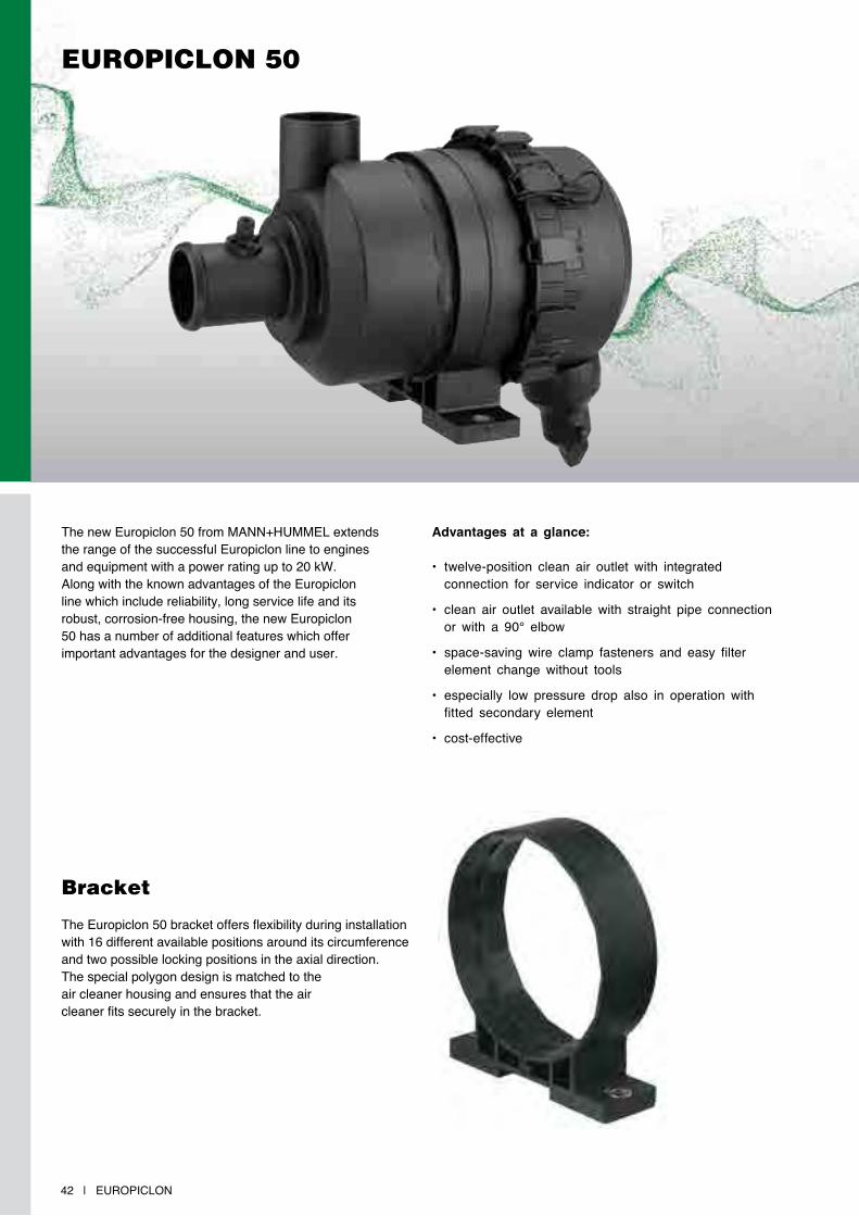
EUROPICLON 50
The new Europiclon 50 from MANN+HUMMEL extends the range of the successful Europiclon line to engines and equipment with a power rating up to 20 kW. Along with the known advantages of the Europiclon line which include reliability, long service life and its robust, corrosion-free housing, the new Europiclon 50 has a number of additional features which offer important advantages for the designer and user.
Advantages at a glance:
• twelve-position clean air outlet with integrated connection for service indicator or switch
• clean air outlet available with straight pipe connection or with a 90° elbow
• space-saving wire clamp fasteners and easy filter element change without tools
• especially low pressure drop also in operation with fitted secondary element
• cost-effective
Bracket
The Europiclon 50 bracket offers flexibility during installation with 16 different available positions around its circumference and two possible locking positions in the axial direction. The special polygon design is matched to the air cleaner housing and ensures that the air cleaner fits securely in the bracket.
EUROPICLON | 43
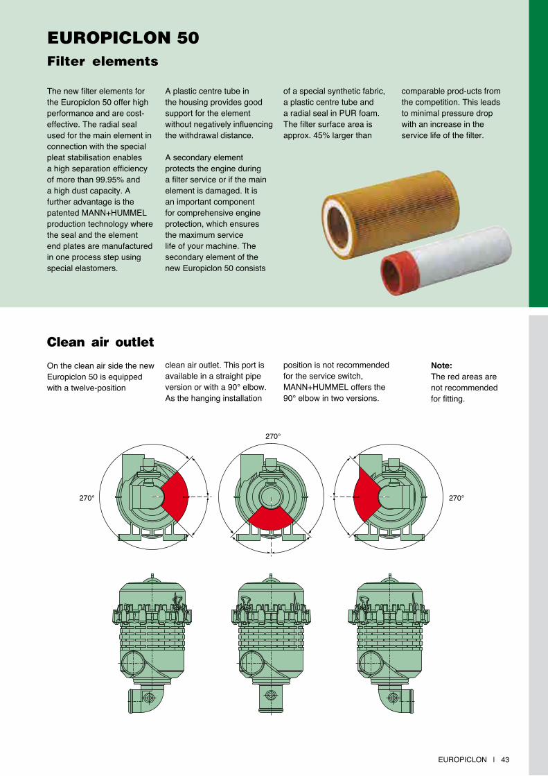
Clean air outlet
On the clean air side the new Europiclon 50 is equipped with a twelve-position
clean air outlet. This port is available in a straight pipe version or with a 90° elbow. As the hanging installation
position is not recommended for the service switch, MANN+HUMMEL offers the 90° elbow in two versions.
EUROPICLON 50Filter elements
The new filter elements for the Europiclon 50 offer high performance and are cost-effective. The radial seal used for the main element in connection with the special pleat stabilisation enables a high separation efficiency of more than 99.95% and a high dust capacity. A further advantage is the patented MANN+HUMMEL production technology where the seal and the element end plates are manufactured in one process step using special elastomers.
A plastic centre tube in the housing provides good support for the element without negatively influencing the withdrawal distance.
A secondary element protects the engine during a filter service or if the main element is damaged. It is an important component for comprehensive engine protection, which ensures the maximum service life of your machine. The secondary element of the new Europiclon 50 consists
of a special synthetic fabric, a plastic centre tube and a radial seal in PUR foam. The filter surface area is approx. 45% larger than
comparable prod-ucts from the competition. This leads to minimal pressure drop with an increase in the service life of the filter.
Note: The red areas are not recommended for fitting.
270°
270°270°
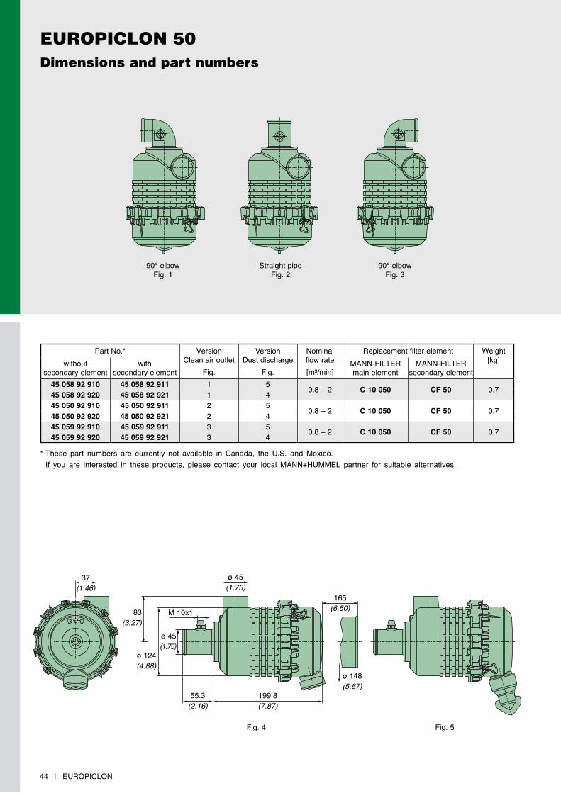
EUROPICLON 50Dimensions and part numbers
44 | EUROPICLON
Part No.* VersionClean air outlet
Fig.
VersionDust discharge
Fig.
Nominal flow rate [m³/min]
Replacement filter element Weight[kg]without
secondary elementwith
secondary elementMANN-FILTERmain element
MANN-FILTERsecondary element
45 058 92 910 45 058 92 911 1 5 0.8 – 2 C 10 050 CF 50 0.745 058 92 920 45 058 92 921 1 445 050 92 910 45 050 92 911 2 5 0.8 – 2 C 10 050 CF 50 0.745 050 92 920 45 050 92 921 2 445 059 92 910 45 059 92 911 3 5 0.8 – 2 C 10 050 CF 50 0.745 059 92 920 45 059 92 921 3 4
90° elbowFig. 1
Straight pipeFig. 2
90° elbowFig. 3
37(1.46)
ø 45(1.75)
165(6.50)
ø 148(5.67)
55.3(2.16)
Fig. 4 Fig. 5
ø 45(1.75)
83(3.27)
ø 124(4.88)
M 10x1
199.8(7.87)
* These part numbers are currently not available in Canada, the U.S. and Mexico. If you are interested in these products, please contact your local MANN+HUMMEL partner for suitable alternatives.
EUROPICLON | 45
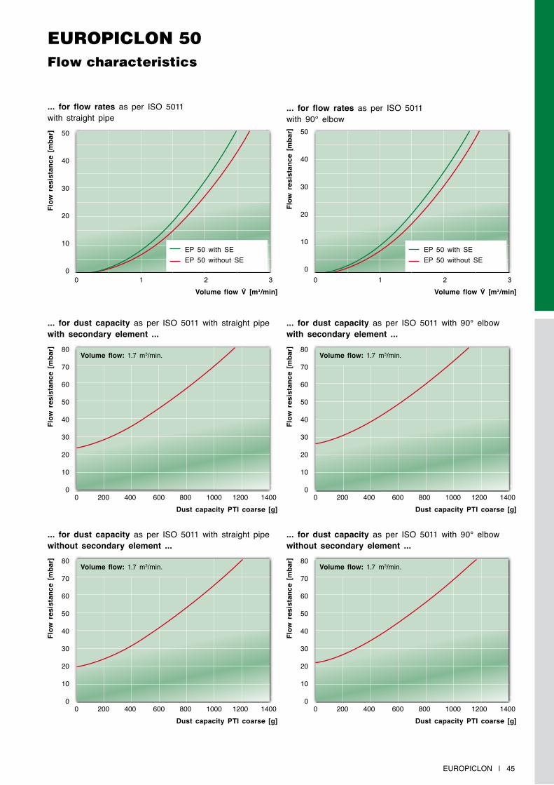
EUROPICLON 50Flow characteristics
... for flow rates as per ISO 5011 with straight pipe
Flow
res
ista
nce
[mba
r]
Volume flow V̇ [m3/min] Volume flow V̇ [m3/min]0 1 2 3 0 1 2 3
50
40
30
20
10
0
50
40
30
20
10
0
EP 50 with SEEP 50 without SE
EP 50 with SEEP 50 without SE
... for dust capacity as per ISO 5011 with straight pipe with secondary element ...
Flow
res
ista
nce
[mba
r]
Dust capacity PTi coarse [g]0 200 400 600 800 1000 1200 1400
80
70
60
50
40
30
20
10
0
Volume flow: 1.7 m3/min.
... for flow rates as per ISO 5011 with 90° elbow
Flow
res
ista
nce
[mba
r]
Flow
res
ista
nce
[mba
r]
Dust capacity PTi coarse [g]0 200 400 600 800 1000 1200 1400
80
70
60
50
40
30
20
10
0
Volume flow: 1.7 m3/min.
... for dust capacity as per ISO 5011 with straight pipe without secondary element ...
Flow
res
ista
nce
[mba
r]
... for dust capacity as per ISO 5011 with 90° elbow with secondary element ...
Dust capacity PTi coarse [g]0 200 400 600 800 1000 1200 1400
80
70
60
50
40
30
20
10
0
Volume flow: 1.7 m3/min.
Flow
res
ista
nce
[mba
r]
Dust capacity PTi coarse [g]
... for dust capacity as per ISO 5011 with 90° elbowwithout secondary element ...
0 200 400 600 800 1000 1200 1400
80
70
60
50
40
30
20
10
0
Volume flow: 1.7 m3/min.
46 | EUROPICLON
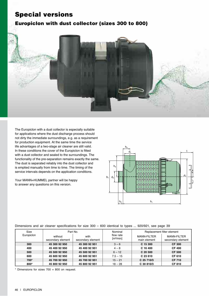
Special versionsEuropiclon with dust collector (sizes 300 to 800)
The Europiclon with a dust collector is especially suitable for applications where the dust discharge process should not dirty the immediate surroundings, e.g. as a requirement for production equipment. At the same time the service life advantages of a two-stage air cleaner are still valid. In these conditions the cover of the Europiclon is fitted with a dust collector and sealed to the surroundings. The functionality of the pre-separation remains exactly the same. The dust is separated reliably into the dust collector and is emptied manually from time to time. The timing of the service intervals depends on the application conditions.
Your MANN+HUMMEL partner will be happy to answer any questions on this version.
Dimensions and air cleaner specifications for size 300 – 600 identical to types ... 920/921, see page 39
SizeEuropiclon
Part No. Nominal flow rate[m³/min]
Replacement filter elementwithout
secondary elementwith
secondary elementMANN-FILTERmain element
MANN-FILTERsecondary element
300 45 300 92 950 45 300 92 951 3 – 6 C 15 300 CF 300400 45 400 92 950 45 400 92 951 4 – 8 C 16 400 CF 400500 45 500 92 950 45 500 92 951 6 – 12 C 20 500 CF 500600 45 600 92 950 45 600 92 951 7.5 – 15 C 23 610 CF 610700* 45 700 92 950 45 700 92 951 15 – 21 C 25 710/3 CF 710800* 45 800 92 950 45 800 92 951 18 – 28 C 30 810/3 CF 810
b1 d2
h4
h2 h1
h3d1 t
d3
* Dimensions for sizes 700 + 800 on request.
EUROPICLON | 47
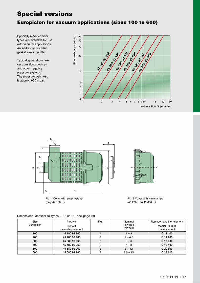
Specially modified filter types are available for use with vacuum applications. An additional moulded gasket seals the filter.
Typical applications are vacuum lifting devices and other negative pressure systems. The pressure tightness is approx. 950 mbar.
Special versionsEuropiclon for vacuum applications (sizes 100 to 600)
Dimensions identical to types ... 920/921, see page 39
SizeEuropiclon
Part No. Fig. Nominal flow rate[m³/min]
Replacement filter elementwithout
secondary elementMANN-FILTERmain element
100 44 180 92 960 1 1 – 3 C 11 100200 45 280 92 960 2 2 – 4.5 C 14 200300 45 380 92 960 2 3 – 6 C 15 300400 45 480 92 960 2 4 – 8 C 16 400500 45 580 92 960 2 6 – 12 C 20 500600 45 680 92 960 2 7.5 – 15 C 23 610
b1 d2
h4
h2 h1
h3
d1
d3
t
Fig. 1 Cover with snap fastener(only 44 180 ...)
Fig. 2 Cover with wire clamps(45 280 ... to 45 680 ...)
Volume flow V̇ [m3/min]
5040
30
20
10
31 2 3 4 5 6 7 8 9 10 15 20 30
4
56
Flow
res
ista
nce
[mba
r]
44 1
80 9
2 96
045
280
92
960
45 3
80 9
2 96
045
480
92
960
45 5
80 9
2 96
045
680
92
960
1 2 3 4 5 6 7 8 9 10 15 20 30
50
40
30
20
10
65
4
3

48 | EUROPICLON
* Alternative design B possible (see page 101) You will find the complete range of accessories for our air cleaners on page 99.
** Accessories only for special designs.
x = 1 bis 8
Dust discharge valves
EUROPICLONAccessories
Filter size Rain cap Straight pipe 90° elbowdesign A *(p. 100)
without connection (p. 104)
with connection (p. 104)
without connection (p. 103)
with connection (p. 103)
Europiclon 50 39 014 67 910 – – – –Europiclon 100 39 020 67 910 39 100 27 999 39 100 27 979 39 100 25 999 39 100 25 979Europiclon 200 39 028 67 910 39 200 27 999 39 200 27 979 39 200 25 999 39 200 25 979Europiclon 300 39 040 67 910 39 300 27 999 39 300 27 979 39 300 25 999 39 300 25 979Europiclon 400 39 056 67 910 39 400 27 999 39 400 27 979 39 400 25 999 39 400 25 979Europiclon 500 39 080 67 910 39 500 27 999 39 500 27 979 39 500 25 999 39 500 25 979Europiclon 600 39 100 67 910 39 600 27 999 39 600 27 979 39 600 25 999 39 600 25 979Europiclon 700** 39 160 67 910 39 700 27 999 39 700 27 979 39 700 25 999 39 700 25 979Europiclon 800** 39 190 67 910 39 800 27 999 39 800 27 979 39 800 25 999 39 800 25 979
Part No. Name Suitable for23 040 30 111 Diaphragm valve 45 x00 92 920/921
39 000 40 391 Small dust discharge valve 45 x00 92 910/911
39 000 40 661 Large dust discharge valve 44 x00 92 940/941
39 000 40 102 Large dust discharge valve 45 x00 92 940/941

EUROPICLON | 49
The brackets are especially designed for the external surface of the Europiclon housing and allow vibration-free mounting of the air cleaner.
From size 700 it is necessary to use two brackets.
EUROPICLONBrackets
e
b
e
d
b
44 400 40 109
‹PAG-GF 30›
a
‹PAG-GF 30›
a
g
c
f f
c
d
g
Fig. 1
50(1.97)
50(1.97)
Fig. 2
Part No. Suitable forEuropiclon
Fig. Dimensions in mm (Dimensions in inches)
a b c d e f g
39 050 40 959 45 05x 92 ... 1 40(1.57)
137(5.39)
116(4.57)
122(4.80)
85.7(3.37)
9(0.35) –
39 100 40 999 45 100 92 ... 1 60(2.36)
205(8.07)
175(6.89)
156(6.14)
105(4.13)
8.5(0.33)
15.5(0.61)
39 200 40 999 45 200 92 ... 1 80(3.15)
220(8.66)
190(7.48)
171(6.73)
110(4.33)
8.5(0.33)
15.5(0.61)
39 300 40 999 45 300 92 ... 1 80(3.15)
250(9.84)
220(8.66)
201(7.91)
125(4.92)
8.5(0.33)
15.5(0.61)
39 400 40 999 45 400 92 ... 1 80(3.15)
270(10.63)
240(9.45)
221(8.70)
135(5.32)
8.5(0.33)
15.5(0.61)
39 500 40 999 45 500 92 ... 1 80(3.15)
310(12.20)
280(11.02)
262(10.32)
155(6.10)
8.5(0.33)
15.5(0.61)
39 600 40 999 45 600 92 ... 1 80(3.15)
345(13.58)
315(12.40)
296(11.65)
173(6.81)
8.5(0.33)
15.5(0.61)
39 700 40 999 45 700 92 ... 1 80(3.15)
385(15.16)
355(13.98)
326(12.83)
206(8.11)
8.5(0.33)
7.0(0.28)
39 800 40 999 45 800 92 ... 1 80(3.15)
452(17.80)
422(16.61)
391(15.39)
220(8.66)
8.5(0.33)
7.0(0.28)
39 100 40 989 45 100 92 ... 2 50(1.97)
110(4.33)
80(3.15)
156(6.14)
100(3.94)
8.5(0.33) –
39 200 40 989 45 200 92 ... 2 50(1.97)
125(4.92)
95(3.74)
171(6.73)
106(4.17)
8.5(0.33) –
39 300 40 989 45 300 92 ... 2 50(1.97)
140(5.51)
110(4.33)
201(7.91)
121(4.76)
8.5(0.33) –
39 400 40 989 45 400 92 ... 2 50(1.97)
157(6.18)
127(5.00)
221(8.70)
132(5.20)
8.5(0.33) –
39 500 40 989 45 500 92 ... 2 50(1.97)
182(7.17)
152(5.98)
262(10.32)
153(6.02)
8.5(0.33) –
39 600 40 989 45 600 92 ... 2 50(1.97)
182(7.17)
152(5.98)
296(11.65)
173(6.81)
8.5(0.33) –
39 700 40 989 45 700 92 ... 2 50(1.97)
233(9.17)
203(7.99)
326(12.83)
206(8.11)
8.5(0.33) –
39 800 40 989 45 800 92 ... 2 50(1.97)
233(9.17)
203(7.99)
391(15.39)
221(8.70)
8.5(0.33) –
50 | EUROPICLON
EUROPICLON Additional spare parts
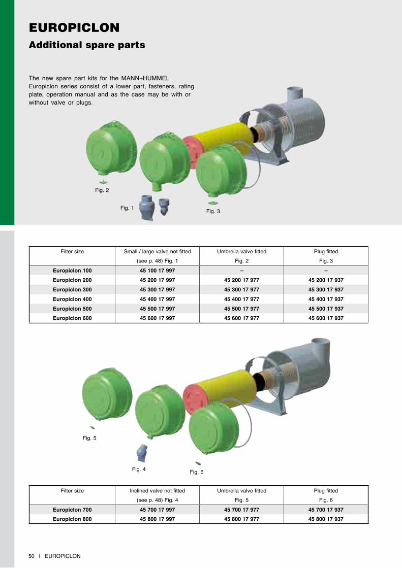
The new spare part kits for the MANN+HUMMEL Europiclon series consist of a lower part, fasteners, rating plate, operation manual and as the case may be with or without valve or plugs.
Filter size Small / large valve not fitted Umbrella valve fitted Plug fitted(see p. 48) Fig. 1 Fig. 2 Fig. 3
Europiclon 100 45 100 17 997 – –Europiclon 200 45 200 17 997 45 200 17 977 45 200 17 937Europiclon 300 45 300 17 997 45 300 17 977 45 300 17 937Europiclon 400 45 400 17 997 45 400 17 977 45 400 17 937Europiclon 500 45 500 17 997 45 500 17 977 45 500 17 937Europiclon 600 45 600 17 997 45 600 17 977 45 600 17 937
Filter size Inclined valve not fitted Umbrella valve fitted Plug fitted(see p. 48) Fig. 4 Fig. 5 Fig. 6
Europiclon 700 45 700 17 997 45 700 17 977 45 700 17 937Europiclon 800 45 800 17 997 45 800 17 977 45 800 17 937
Fig. 1
Fig. 2
Fig. 3
Fig. 4 Fig. 6
Fig. 5

NLG | 51
MANN+HUMMEL NLGModular air cleaner system for a wide range of applications

52 | NLG
NLGFlexible – Robust – Economical
The Pico is the single-stage version of the NLG, i.e. without integrated dust pre-separation. It is particularly suitable for applications with low dust loads where minimal pressure drop in the air cleaner is a special requirement.
These are, for example:
• commercial vehicles (trucks)
• buses
• mobile cranes
• compressors
• stationary engines
• generators
• marine applications
NLG PicoSingle-stage air cleaners
The new NLG line from MANN+HUMMEL offers a flexible and economic solution for many varied applications in the field of intake air filtration.
Advantages at a glance:
• high flexibility through variable modular system
• economic air cleaner system through modular design
• easy element change without tools
• corrosion-free and robust housing through use of plastic reinforced with fibreglass
• the Piclon version with integrated dust pre-separation can also be used with medium to heavy dust loads
• as a combination air cleaner with DualSpin precleaner also suitable for very difficult dust conditions due to its long service life
• metal-free filter elements are easily disposed of by incineration and therefore are environmentally friendly with inexpensive disposal
• problem-free adaptation to other equipment through variable connection positions
• quick first-fit on the vehicle through threaded inserts
• patented filter elements
clean air outlet
dirty air connection
Pico filter element
housing in plastic reinforced with fibre-glass
secondary element (optional)
water discharge valve on the housing; not shown here
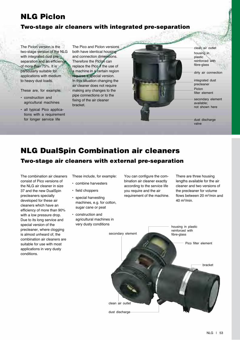
NLG | 53
bracket
Pico filter element
dust discharge
housing in plastic reinforced with fibre-glass
clean air outlet
secondary element
NLG PiclonTwo-stage air cleaners with integrated pre-separation
NLG DualSpin Combination air cleanersTwo-stage air cleaners with external pre-separation
The Piclon version is the two-stage version of the NLG with integrated dust pre-separation and an efficiency of more than 75%. It is particularly suitable for applications with medium to heavy dust loads.
These are, for example:
• construction and agricultural machines
• all typical Pico applica-tions with a requirement for longer service life
The combination air cleaners consist of Pico versions of the NLG air cleaner in size 37 and the new DualSpin precleaners specially developed for these air cleaners which have an efficiency of more than 90% with a low pressure drop. Due to its long service and special version of the precleaner, where clogging is almost unheard of, the combination air cleaners are suitable for use with most applications in very dusty conditions.
The Pico and Piclon versions both have identical housing and connection dimensions. Therefore the Piclon can replace the Pico if the use of a machine in a certain region requires a special version. In this situation changing the air cleaner does not require making any changes to the pipe connections or to the fixing of the air cleaner bracket.
These include, for example:
• combine harvesters
• field choppers
• special harvesting machines, e.g. for cotton, sugar cane or peat
• construction and agricultural machines in very dusty conditions
You can configure the com-bination air cleaner exactly according to the service life you require and the air requirement of the machine.
There are three housing lengths available for the air cleaner and two versions of the precleaner for volume flows between 20 m3/min and 40 m3/min.
clean air outlethousing in plastic reinforced with fibre-glass
dirty air connection
Piclon filter element
dust discharge valve
secondary element available; not shown here
integrated dust precleaner
54 | NLG
NLG Modular system
NLG Modular system
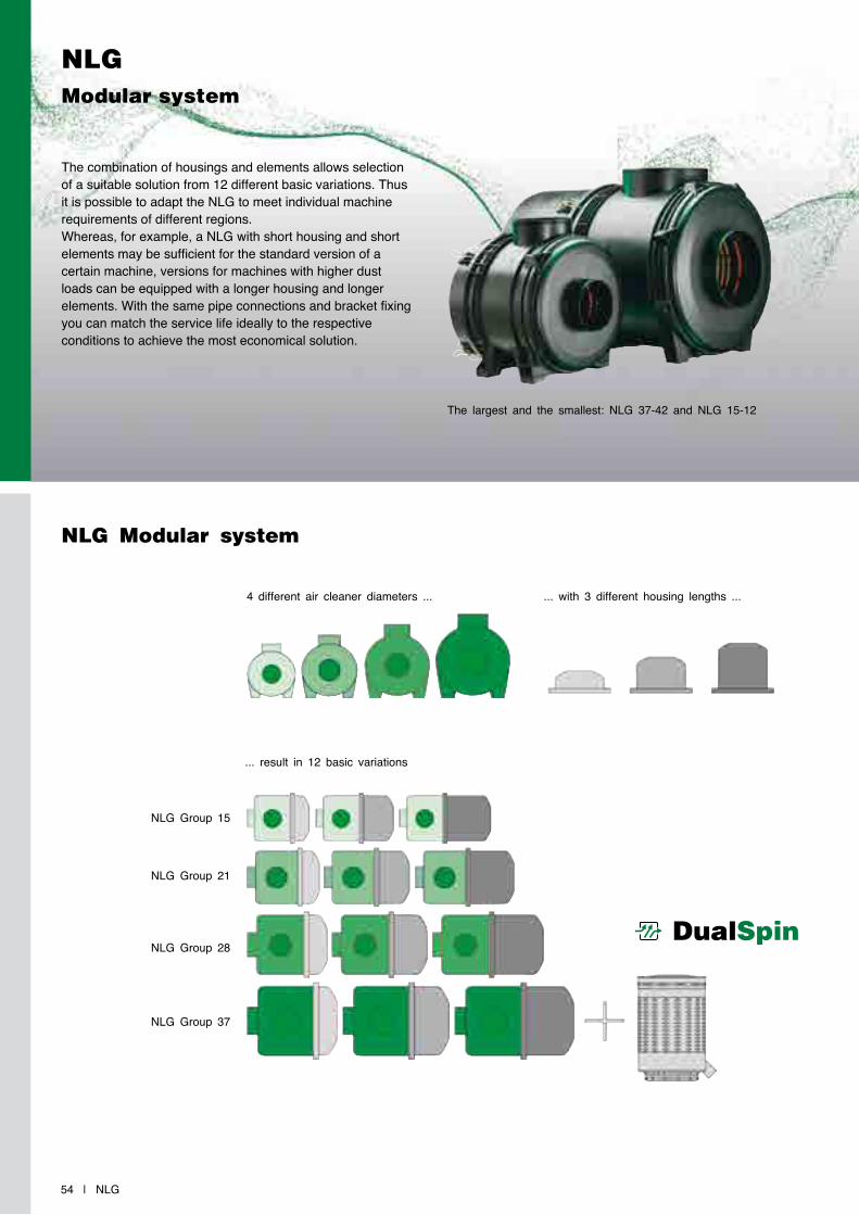
The combination of housings and elements allows selection of a suitable solution from 12 different basic variations. Thus it is possible to adapt the NLG to meet individual machine requirements of different regions. Whereas, for example, a NLG with short housing and short elements may be sufficient for the standard version of a certain machine, versions for machines with higher dust loads can be equipped with a longer housing and longer elements. With the same pipe connections and bracket fixing you can match the service life ideally to the respective conditions to achieve the most economical solution.
4 different air cleaner diameters ... ... with 3 different housing lengths ...
... result in 12 basic variations
NLG Group 37
NLG Group 28
NLG Group 21
NLG Group 15
The largest and the smallest: NLG 37-42 and NLG 15-12
DualSpin
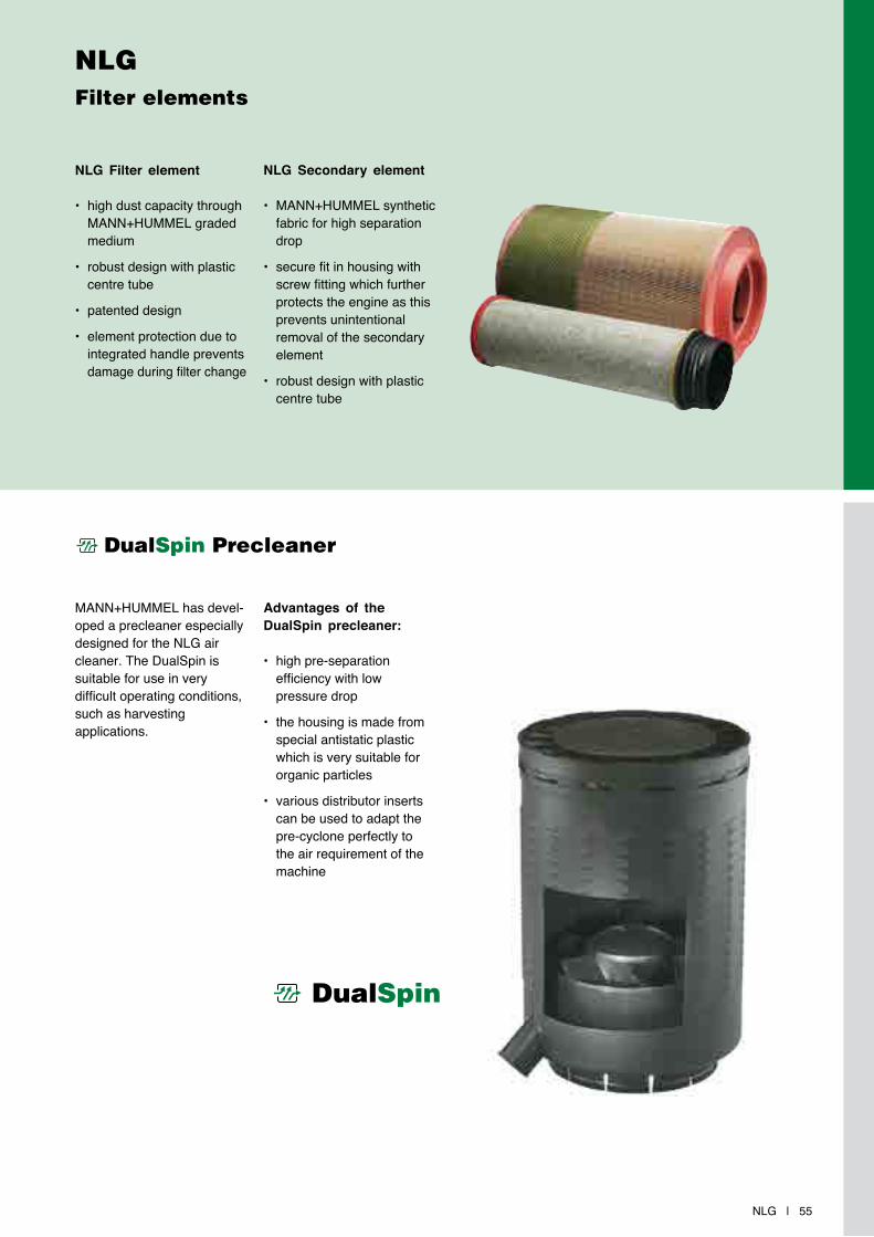
NLG | 55
NLG Filter elements
NLG Filter element
• high dust capacity through MANN+HUMMEL graded medium
• robust design with plastic centre tube
• patented design
• element protection due to integrated handle prevents damage during filter change
MANN+HUMMEL has devel-oped a precleaner especially designed for the NLG air cleaner. The DualSpin is suitable for use in very difficult operating conditions, such as harvesting applications.
Advantages of the DualSpin precleaner:
• high pre-separation efficiency with low pressure drop
• the housing is made from special antistatic plastic which is very suitable for organic particles
• various distributor inserts can be used to adapt the pre-cyclone perfectly to the air requirement of the machine
NLG Secondary element
• MANN+HUMMEL synthetic fabric for high separation drop
• secure fit in housing with screw fitting which further protects the engine as this prevents unintentional removal of the secondary element
• robust design with plastic centre tube
DualSpin
DualSpin Precleaner

NLG Pico (1-stage)Dimensions and part numbers
56 | NLG Pico
NLG Pico version with connection dimension d1 = 250 mm (9.84 inch)
* Pleat height 48 mm (1.89 inch) ** Pleat height 60 mm (2.36 inch)
Filter size Part No. Fig. Nominal flow rate[m3/min]
Replacement filter element Weight[kg]without
secondary elementwith
secondary elementMANN-FILTERmain element
MANN-FILTERsecondary elemen
NLG 15-1244 513 85 901 44 513 85 950 1
10 – 18 C 23 513 CF 1240 3.344 513 85 902 44 513 85 951 244 513 85 900 44 513 85 952 3
NLG 15-1544 632 85 905 44 632 85 951 1
10 – 18 C 23 632/1 CF 1250 3.644 632 85 906 44 632 85 952 244 632 85 900 44 632 85 950 3
NLG 15-1844 750 85 903 44 750 85 951 1
10 – 18 C 23 750 CF 1260 4.344 750 85 904 44 750 85 950 244 750 85 901 44 750 85 952 3
NLG 21-1844 742 85 905 44 742 85 950 1
12 – 24 C 25 740 CF 1420 4.344 742 85 906 44 742 85 952 244 742 85 904 44 742 85 953 3
NLG 21-2144 860 85 908 44 860 85 952 1
12 – 24 C 25 860/5 CF 1430 4.644 860 85 909 44 860 85 953 244 860 85 900 44 860 85 951 3
NLG 21-2444 860 85 911 44 860 85 954 1
12 – 24 C 25 990 CF 1440 5.144 860 85 912 44 860 85 950 244 860 85 904 44 860 85 955 3
NLG 28-2444 920 85 926 44 920 85 950 1
18 – 30 C 27 1020 CF 1631 5.244 920 85 927 44 920 85 955 244 920 85 916 44 920 85 956 3
NLG 28-2844 920 85 915 44 920 85 954 1
18 – 30 C 27 1170 CF 1640 5.644 920 85 914 44 920 85 957 244 920 85 904 44 920 85 952 3
NLG 28-3244 920 85 928 44 920 85 958 1
18 – 30 C 27 1320/2 CF 1650 6.344 920 85 924 44 920 85 951 244 920 85 918 44 920 85 959 3
NLG 37-3244 930 85 912 44 930 85 950 1
25 – 45 C 30 1330 CF 1820 6.444 930 85 913 44 930 85 956 244 930 85 902 44 930 85 957 3
NLG 37-3744 930 85 908 44 930 85 958 1
25 – 45 C 30 1530 CF 1830 7.444 930 85 909 44 930 85 959 244 930 85 900 44 930 85 951 3
NLG 37-4244 930 85 914 44 930 85 955 1
25 – 45 C 30 1730 CF 1840 7.944 930 85 915 44 930 85 952 244 930 85 901 44 930 85 954 3
Filter size Part No. Fig. Nominal flow rate[m3/min]
Replacement filter element Weight[kg]without
secondary elementwith
secondary elementMANN-FILTERmain elementt
MANN-FILTERsecondary element
NLG 37-37 – 44 930 85 953* 1 25 – 45 C 30 1530 CF 1830 8.3NLG 37-42 – 44 930 85 960* 1 25 – 45 C 30 1730 CF 1840 8.7NLG 37-42 – 44 930 85 974** 2 25 – 45 C 33 2200 CF 1840 9.4NLG 37-42 – 44 930 85 975** 1 25 – 45 C 33 2200 CF 1840 9.4
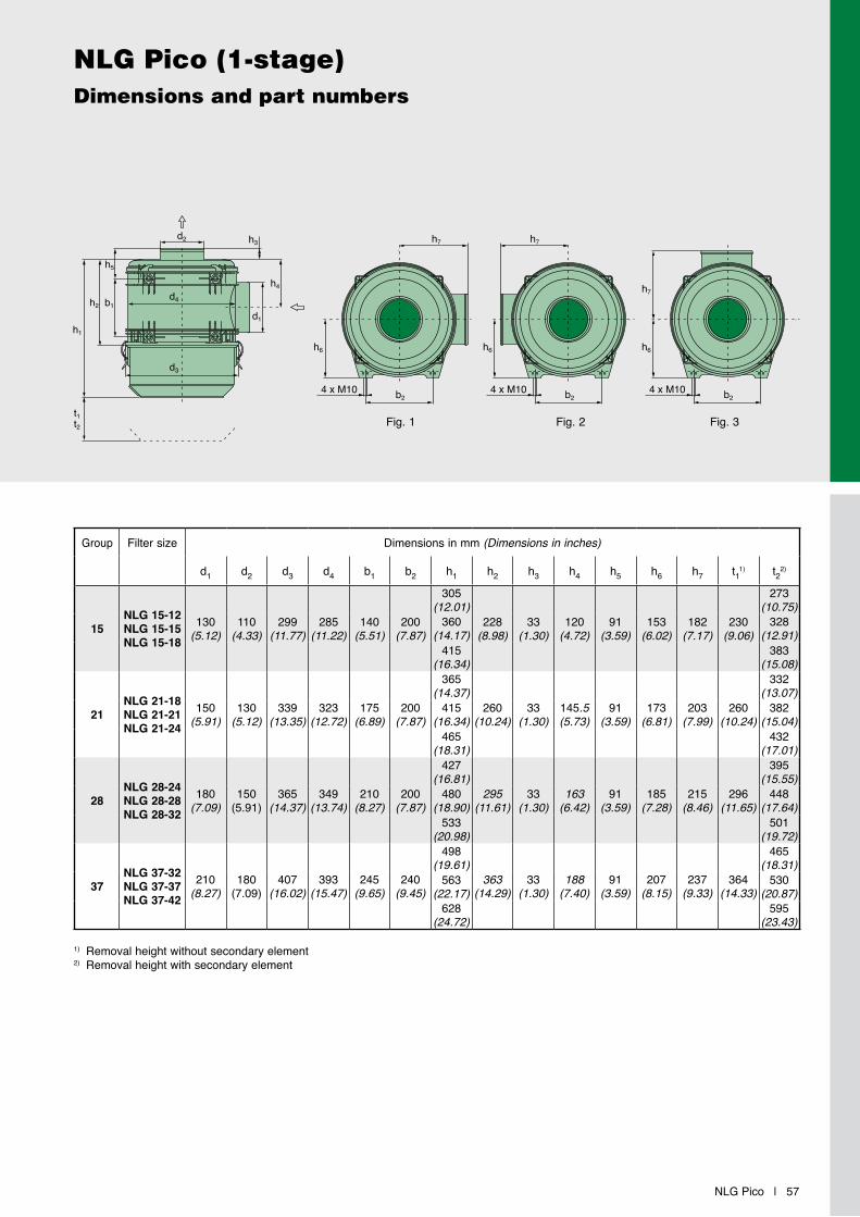
NLG Pico | 57
NLG Pico (1-stage)Dimensions and part numbers
1) Removal height without secondary element2) Removal height with secondary element
Group Filter size Dimensions in mm (Dimensions in inches)
d1 d2 d3 d4 b1 b2 h1 h2 h3 h4 h5 h6 h7 t11) t22)
15NLG 15-12NLG 15-15NLG 15-18
130(5.12)
110(4.33)
299(11.77)
285(11.22)
140(5.51)
200(7.87)
305(12.01)
228(8.98)
33(1.30)
120(4.72)
91(3.59)
153(6.02)
182(7.17)
230(9.06)
273(10.75)
360(14.17)
328(12.91)
415(16.34)
383(15.08)
21NLG 21-18NLG 21-21NLG 21-24
150(5.91)
130(5.12)
339(13.35)
323(12.72)
175(6.89)
200(7.87)
365(14.37)
260(10.24)
33(1.30)
145.5(5.73)
91(3.59)
173(6.81)
203(7.99)
260(10.24)
332(13.07)
415(16.34)
382(15.04)
465(18.31)
432(17.01)
28NLG 28-24NLG 28-28NLG 28-32
180(7.09)
150(5.91)
365(14.37)
349(13.74)
210(8.27)
200(7.87)
427(16.81)
295(11.61)
33(1.30)
163(6.42)
91(3.59)
185(7.28)
215(8.46)
296(11.65)
395(15.55)
480(18.90)
448(17.64)
533(20.98)
501(19.72)
37NLG 37-32NLG 37-37NLG 37-42
210(8.27)
180(7.09)
407(16.02)
393(15.47)
245(9.65)
240(9.45)
498(19.61)
363(14.29)
33(1.30)
188(7.40)
91(3.59)
207(8.15)
237(9.33)
364(14.33)
465(18.31)
563(22.17)
530(20.87)
628(24.72)
595(23.43)
Fig. 1 Fig. 2 Fig. 3
b2
h7
h6
4 x M10 b2
h6
h7
4 x M10b2
h7
h6
4 x M10b2
h7
h6
4 x M10 b2
h6
h7
4 x M10b2
h7
h6
4 x M10b2
h7
h6
4 x M10 b2
h6
h7
4 x M10b2
h7
h6
4 x M10
h1
h2
h5
b1
d2
d3
d4
h3
h4
d1
t1t2
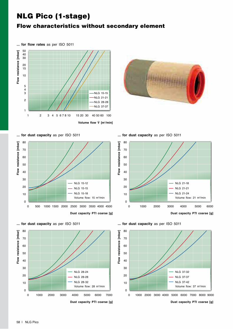
NLG Pico (1-stage)Flow characteristics without secondary element
58 | NLG Pico
... for flow rates as per ISO 5011
Flow
res
ista
nce
[mba
r]
Volume flow V̇ [m3/min]
1 2 3 4 5 6 7 8 10 15 20 30 40 50 60 100
504030
2015
10
543
2
1
... for dust capacity as per ISO 5011
... for dust capacity as per ISO 5011
... for dust capacity as per ISO 5011
... for dust capacity as per ISO 5011
Flow
res
ista
nce
[mba
r]Fl
ow r
esis
tanc
e [m
bar]
Flow
res
ista
nce
[mba
r]Fl
ow r
esis
tanc
e [m
bar]
Dust capacity PTI coarse [g]
Dust capacity PTI coarse [g]
Dust capacity PTI coarse [g]
Dust capacity PTI coarse [g]
0 500 1000 1500 2000 2500 3000 3500 4000 4500
0 1000 2000 3000 4000 5000 6000 7000
0 1000 2000 3000 4000 5000 6000
0 1000 2000 3000 4000 5000 6000 7000 8000 9000
80
70
60
50
40
30
20
10
0
80
70
60
50
40
30
20
10
0
80
70
60
50
40
30
20
10
0
80
70
60
50
40
30
20
10
0
NLG 15-12
NLG 15-15
NLG 15-18Volume flow: 15 m3/min
NLG 28-24
NLG 28-28
NLG 28-32Volume flow: 28 m3/min
NLG 21-18
NLG 21-21
NLG 21-24Volume flow: 21 m3/min
NLG 37-32
NLG 37-37
NLG 37-42Volume flow: 37 m3/min
NLG 15-15NLG 21-21NLG 28-28NLG 37-37
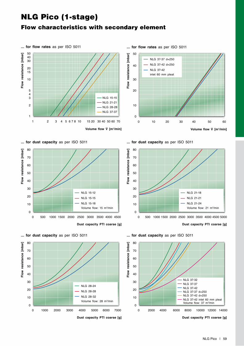
NLG Pico | 59
NLG Pico (1-stage)Flow characteristics with secondary element
... for flow rates as per ISO 5011
Flow
res
ista
nce
[mba
r]
Volume flow V̇ [m3/min]
1 2 3 4 5 6 7 8 10 15 20 30 40 50 60 70
504030
2015
10
543
2
1
... for dust capacity as per ISO 5011
... for dust capacity as per ISO 5011
... for dust capacity as per ISO 5011
... for dust capacity as per ISO 5011
Flow
res
ista
nce
[mba
r]Fl
ow r
esis
tanc
e [m
bar]
Flow
res
ista
nce
[mba
r]Fl
ow r
esis
tanc
e [m
bar]
Dust capacity PTI coarse [g]
Dust capacity PTI coarse [g]
Dust capacity PTI coarse [g]
Dust capacity PTI coarse [g]
0 500 1000 1500 2000 2500 3000 3500 4000 4500
0 1000 2000 3000 4000 5000 6000 7000
0 500 1000 1500 2000 2500 3000 3500 4000 4500 5000
0 2000 4000 6000 8000 10000 12000 14000
80
70
60
50
40
30
20
10
0
80
70
60
50
40
30
20
10
0
80
70
60
50
40
30
20
10
0
80
70
60
50
40
30
20
10
0
NLG 15-12
NLG 15-15
NLG 15-18Volume flow: 15 m3/min
NLG 28-24
NLG 28-28
NLG 28-32Volume flow: 28 m3/min
NLG 21-18
NLG 21-21
NLG 21-24Volume flow: 21 m3/min
NLG 37-32NLG 37-37NLG 37-42NLG 37-37 d=250NLG 37-42 d=250NLG 37-42 inlet 60 mm pleatVolume flow: 37 m3/min
... for flow rates as per ISO 5011
Flow
res
ista
nce
[mba
r]Volume flow V̇ [m3/min]
0 10 20 30 40 50 60
50
40
30
20
10
0
NLG 37-37 d=250
NLG 37-42 d=250
NLG 37-42inlet 60 mm pleat
NLG 15-15NLG 21-21NLG 28-28NLG 37-37
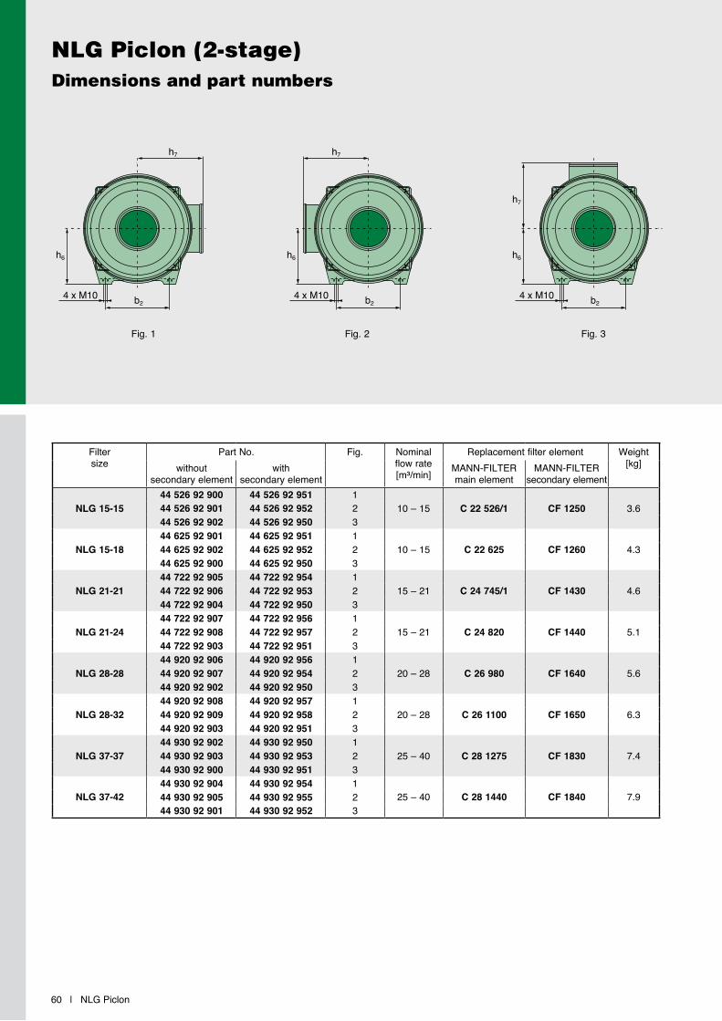
NLG Piclon (2-stage)Dimensions and part numbers
60 | NLG Piclon
Fig. 1 Fig. 2 Fig. 3
Filter size
Part No. Fig. Nominal flow rate[m³/min]
Replacement filter element Weight[kg]without
secondary elementwith
secondary elementMANN-FILTERmain element
MANN-FILTERsecondary element
NLG 15-1544 526 92 900 44 526 92 951 1
10 – 15 C 22 526/1 CF 1250 3.644 526 92 901 44 526 92 952 244 526 92 902 44 526 92 950 3
NLG 15-1844 625 92 901 44 625 92 951 1
10 – 15 C 22 625 CF 1260 4.344 625 92 902 44 625 92 952 244 625 92 900 44 625 92 950 3
NLG 21-2144 722 92 905 44 722 92 954 1
15 – 21 C 24 745/1 CF 1430 4.644 722 92 906 44 722 92 953 244 722 92 904 44 722 92 950 3
NLG 21-2444 722 92 907 44 722 92 956 1
15 – 21 C 24 820 CF 1440 5.144 722 92 908 44 722 92 957 244 722 92 903 44 722 92 951 3
NLG 28-2844 920 92 906 44 920 92 956 1
20 – 28 C 26 980 CF 1640 5.644 920 92 907 44 920 92 954 244 920 92 902 44 920 92 950 3
NLG 28-3244 920 92 908 44 920 92 957 1
20 – 28 C 26 1100 CF 1650 6.344 920 92 909 44 920 92 958 244 920 92 903 44 920 92 951 3
NLG 37-3744 930 92 902 44 930 92 950 1
25 – 40 C 28 1275 CF 1830 7.444 930 92 903 44 930 92 953 244 930 92 900 44 930 92 951 3
NLG 37-4244 930 92 904 44 930 92 954 1
25 – 40 C 28 1440 CF 1840 7.944 930 92 905 44 930 92 955 244 930 92 901 44 930 92 952 3
b2
h7
h6
4 x M10 b2
h6
h7
4 x M10b2
h7
h6
4 x M10

NLG Piclon | 61
NLG Piclon (2-stage)Dimensions and part numbers
1) Removal height without secondary element2) Removal height with secondary element
Group Filter size Dimensions in mm (Dimensions in inches)
d1 d2 d3 d4 b1 b2 h1 h2 h3 h4 h5 h6 h7 t11) t22)
15 NLG 15-15NLG 15-18
130(5.12)
110(4.33)
299(11.77)
285(11.22)
140(5.51)
200(7.87)
360(14.17)
415(16.34)
228(8.98)
33(1.30)
120(4.72)
91(3.59)
153(6.02)
182(7.17)
230(9.06)
328(12.91)
383(15.08)
21 NLG 21-21NLG 21-24
150(5.91)
130(5.12)
339(13.35)
323(12.72)
175(6.89)
200(7.87)
415(16.34)
465(18.31)
260(10.24)
33(1.30)
145.5(5.73)
91(3.59)
173(6.81)
203(7.99)
260(10.24)
382(15.04)
432(17.01)
28 NLG 28-28NLG 28-32
180(7.09)
150(5.91)
365(14.37)
349(13.74)
210(8.27)
200(7.87)
480(18.90)
533(20.98)
295(11.61)
33(1.30)
163(6.42)
91(3.59)
185(7.28)
215(8.46)
296(11.65)
448(17.64)
501(19.72)
37 NLG 37-37NLG 37-42
210(8.27)
180(7.09)
407(16.02)
393(15.47)
245(9.65)
240(9.45)
563(22.17)
628(24.72)
363(14.29)
33(1.30)
188(7.40)
91(3.59)
207(8.15)
237(9.33)
364(14.33)
530(20.87)
595(23.43)
h1
t1t2
h2
h5
b1
d2
d3
d4
d1
h3
h4
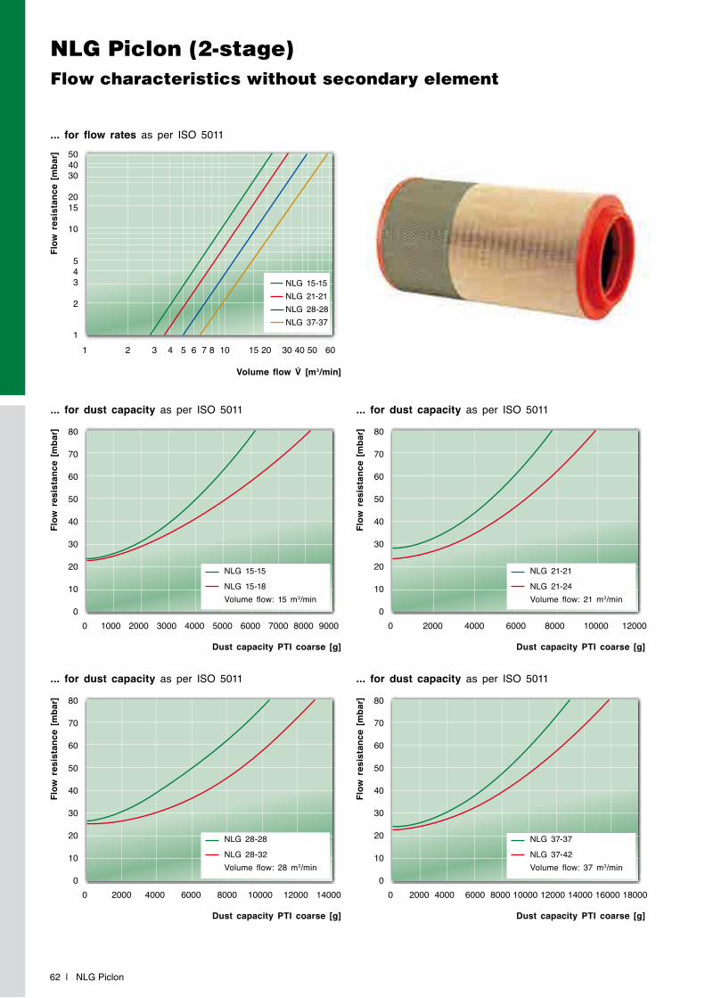
NLG Piclon (2-stage)Flow characteristics without secondary element
62 | NLG Piclon
... for flow rates as per ISO 5011
Flow
res
ista
nce
[mba
r]
Volume flow V̇ [m3/min]
1 2 3 4 5 6 7 8 10 15 20 30 40 50 60
504030
2015
10
543
2
1
... for dust capacity as per ISO 5011
... for dust capacity as per ISO 5011
... for dust capacity as per ISO 5011
... for dust capacity as per ISO 5011
Flow
res
ista
nce
[mba
r]Fl
ow r
esis
tanc
e [m
bar]
Flow
res
ista
nce
[mba
r]Fl
ow r
esis
tanc
e [m
bar]
Dust capacity PTI coarse [g]
Dust capacity PTI coarse [g]
Dust capacity PTI coarse [g]
Dust capacity PTI coarse [g]
0 1000 2000 3000 4000 5000 6000 7000 8000 9000
0 2000 4000 6000 8000 10000 12000 14000
0 2000 4000 6000 8000 10000 12000
0 2000 4000 6000 8000 10000 12000 14000 16000 18000
80
70
60
50
40
30
20
10
0
80
70
60
50
40
30
20
10
0
80
70
60
50
40
30
20
10
0
80
70
60
50
40
30
20
10
0
NLG 15-15
NLG 15-18Volume flow: 15 m3/min
NLG 28-28
NLG 28-32Volume flow: 28 m3/min
NLG 21-21
NLG 21-24Volume flow: 21 m3/min
NLG 37-37
NLG 37-42Volume flow: 37 m3/min
NLG 15-15NLG 21-21NLG 28-28NLG 37-37
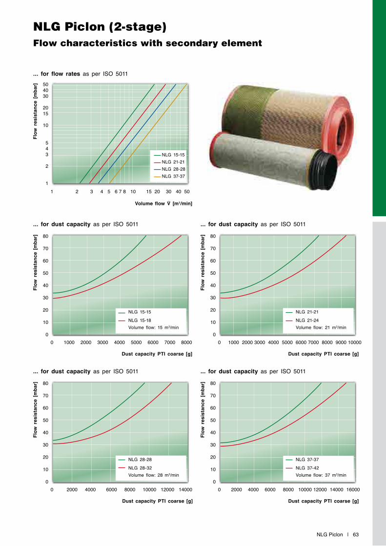
NLG Piclon | 63
NLG Piclon (2-stage)Flow characteristics with secondary element
... for flow rates as per ISO 5011
Flow
res
ista
nce
[mba
r]
Volume flow V̇ [m3/min]
1 2 3 4 5 6 7 8 10 15 20 30 40 50
504030
2015
10
543
2
1
... for dust capacity as per ISO 5011
... for dust capacity as per ISO 5011
... for dust capacity as per ISO 5011
... for dust capacity as per ISO 5011
Flow
res
ista
nce
[mba
r]Fl
ow r
esis
tanc
e [m
bar]
Flow
res
ista
nce
[mba
r]Fl
ow r
esis
tanc
e [m
bar]
Dust capacity PTI coarse [g]
Dust capacity PTI coarse [g]
Dust capacity PTI coarse [g]
Dust capacity PTI coarse [g]
0 1000 2000 3000 4000 5000 6000 7000 8000
0 2000 4000 6000 8000 10000 12000 14000
0 1000 2000 3000 4000 5000 6000 7000 8000 9000 10000
0 2000 4000 6000 8000 10000 12000 14000 16000
80
70
60
50
40
30
20
10
0
80
70
60
50
40
30
20
10
0
80
70
60
50
40
30
20
10
0
80
70
60
50
40
30
20
10
0
NLG 15-15
NLG 15-18Volume flow: 15 m3/min
NLG 28-28
NLG 28-32Volume flow: 28 m3/min
NLG 21-21
NLG 21-24Volume flow: 21 m3/min
NLG 37-37
NLG 37-42Volume flow: 37 m3/min
NLG 15-15NLG 21-21NLG 28-28NLG 37-37
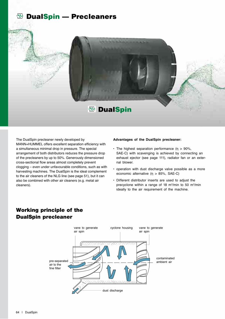
64 | DualSpin
DualSpin — Precleaners
DualSpin
The DualSpin precleaner newly developed by MANN+HUMMEL offers excellent separation efficiency with a simultaneous minimal drop in pressure. The special arrangement of both distributors reduces the pressure drop of the precleaners by up to 50%. Generously dimensioned cross-sectional flow areas almost completely prevent clogging – even under unfavourable conditions, such as with harvesting machines. The DualSpin is the ideal complement to the air cleaners of the NLG line (see page 51), but it can also be combined with other air cleaners (e.g. metal air cleaners).
Advantages of the DualSpin precleaner:
• The highest separation performance (η > 90%,SAE-C) with scavenging is achieved by connecting an exhaust ejector (see page 111), radiator fan or an exter-nal blower.
• operation with dust discharge valve possible as a more economic alternative (η > 85%, SAE-C)
• Different distributor inserts are used to adjust the precyclone within a range of 18 m3/min to 50 m3/min ideally to the air requirement of the machine.
Working principle of the DualSpin precleaner
vane to generate air spin
vane to generate air spin
cyclone housing
dust discharge
contaminated ambient airpre-separated
air to the fine filter
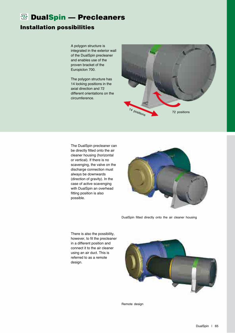
DualSpin | 65
A polygon structure is integrated in the exterior wall of the DualSpin precleaner and enables use of the proven bracket of the Europiclon 700.
The polygon structure has 14 locking positions in the axial direction and 72 different orientations on the circumference.
The DualSpin precleaner can be directly fitted onto the air cleaner housing (horizontal or vertical). If there is no scavenging, the valve on the discharge connection must always be downwards (direction of gravity). In the case of active scavenging with DualSpin an overhead fitting position is also possible.
There is also the possibility, however, to fit the precleaner in a different position and connect it to the air cleaner using an air duct. This is referred to as a remote design.
DualSpin — PrecleanersInstallation possibilities
14 positions72 positions
DualSpin fitted directly onto the air cleaner housing
Remote design

DualSpin Combination air cleaners (2-stage)Dimensions and part numbers
66 | DualSpin
Fig. 2 (with dust discharge valve 39 000 40 671)Fig. 1 (scavenging)
NLG Pico to be used with DualSpin
DualSpin precleaners
Filter size Part No. Connection dimension in mm (inch)
(see page 57)
Replacement filter elementwith
secondary elementMANN-FILTERmain element
MANN-FILTERsecondary element
NLG 37-37 44 930 85 953* 250 (9.84) C 30 1530 CF 1830NLG 37-42 44 930 85 960* 250 (9.84) C 30 1730 CF 1840NLG 37-42 44 930 85 974** 250 (9.84) C 33 2200 CF 1840NLG 37-42 44 930 85 975** 250 (9.84) C 33 2200 CF 1840
Installation size
Bracket suitable for preseparator
(option)
Part No.without dust discharge valve
(Fig. 1)
Part No.with dust discharge valve
(Fig. 2)
Nominal flow rate[m³/min]
Weight[kg]
DualSpin 25 39 700 40 999 48 025 75 900 48 025 75 910 18 – 25 2.4DualSpin 37 39 700 40 999 48 037 75 910 48 037 75 920 25 – 50 2.4
* Pleat height 48 mm (1.89 inch) ** Pleat height 60 mm (2.36 inch)
ø 332(13.07)
508(20.00)
508(20.00)
ø 332(13.07)
38.5(1.52)
38.5(1.52)
ø 250(9.84)
81.5(3.21)
ø 250(9.84)
ø 54
(2.13
)263(10.35)

DualSpin | 67
DualSpin Combination air cleaners (2-stage)Flow characteristics with secondary element
... for dust capacity as per ISO 5011 Precleaner: DualSpin 25 with valve
Flow
res
ista
nce
[mba
r]Fl
ow r
esis
tanc
e [m
bar]
Dust capacity PTI coarse [g]
Dust capacity PTI coarse [g]
0 5000 10000 15000 20000 25000 30000 35000 40000 45000
0 10000 20000 30000 40000
80
70
60
50
40
30
20
10
0
80
70
60
50
40
30
20
10
0
Flow
res
ista
nce
[mba
r]Fl
ow r
esis
tanc
e [m
bar]
... for dust capacity as per ISO 5011 Precleaner: DualSpin 25 with scavenging
Dust capacity PTI coarse [g]
Dust capacity PTI coarse [g]
... for dust capacity as per ISO 5011 Precleaner: DualSpin 37 with valve
... for dust capacity as per ISO 5011 Precleaner: DualSpin 37 with scavenging
0 10000 20000 30000 40000 50000 60000
0 10000 20000 30000 40000 50000 60000
80
70
60
50
40
30
20
10
0
80
70
60
50
40
30
20
10
0
... for flow rates as per ISO 5011
Flow
res
ista
nce
[mba
r]
Volume flow V̇ [m3/min]
0 10 20 30 40 50 60
50
40
30
20
10
0
NLG 37 + DualSpin 25
NLG 37 + DualSpin 37
NLG 37-42 + DualSpin 37inlet 60 mm pleat
NLG 37-37
NLG 37-42Volume flow: 25 m3/minScavenging: none
NLG 37-37
NLG 37-42Volume flow: 37 m3/minScavenging: noneNLG 37-42 60 mminlet 60 mm pleat
NLG 37-37
NLG 37-42Volume flow: 25 m3/minScavenging: 10%
NLG 37-37
NLG 37-42Volume flow: 37 m3/minScavenging: 10%NLG 37-42 60 mminlet 60 mm pleat

68 | NLG
Filter size Rain cap 1) Straight pipe connection 90° elbowdesign A *
(p. 100)without connection
(p. 104)with connection
(p. 104)without connection
(p. 103)with connection
(p. 103)NLG Group 15 39 160 67 910 39 600 27 999 39 600 27 979 39 600 25 999 39 600 25 979NLG Group 21 39 190 67 910 39 700 27 999 39 700 27 979 39 700 25 999 39 700 25 979NLG Group 28 39 220 67 910 39 800 27 999 39 800 27 979 39 800 25 999 39 800 25 979NLG Group 37 39 370 67 910 39 930 27 999 39 930 27 979 39 930 25 999 39 930 25 979
You will find the complete range of accessories for our air cleaners on page 99.
* Alternative design B possible (see page 101)1) Cr(VI)-free
NLG Accessories
Dust discharge valves
Part No. Name Suitable for
39 000 40 661 Large dust dischargevalve NLG Piclon
23 040 30 121 Water discharge valve NLG Pico
39 000 40 671 Large dust dischargevalve DualSpin
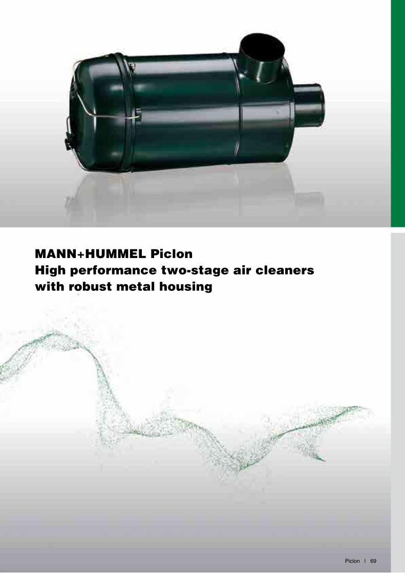
Piclon | 69
MANN+HUMMEL PiclonHigh performance two-stage air cleaners with robust metal housing
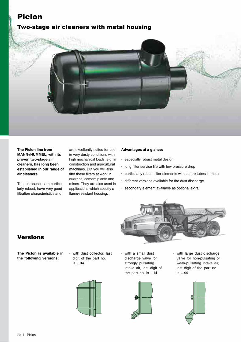
70 | Piclon
PiclonTwo-stage air cleaners with metal housing
Versions
The Piclon line from MANN+HUMMEL, with its proven two-stage air cleaners, has long been established in our range of air cleaners.
The air cleaners are particu-larly robust, have very good filtration characteristics and
The Piclon is available in the following versions:
• with dust collector, last digit of the part no. is ...04
• with a small dust discharge valve for strongly pulsating intake air, last digit of the part no. is ...14
• with large dust discharge valve for non-pulsating or weak-pulsating intake air, last digit of the part no. is ...44
are excellently suited for use in very dusty conditions with high mechanical loads, e.g. in construction and agricultural machines. But you will also find these filters at work in quarries, cement plants and mines. They are also used in applications which specify a flame-resistant housing.
Advantages at a glance:
• especially robust metal design
• long filter service life with low pressure drop
• particularly robust filter elements with centre tubes in metal
• different versions available for the dust discharge
• secondary element available as optional extra
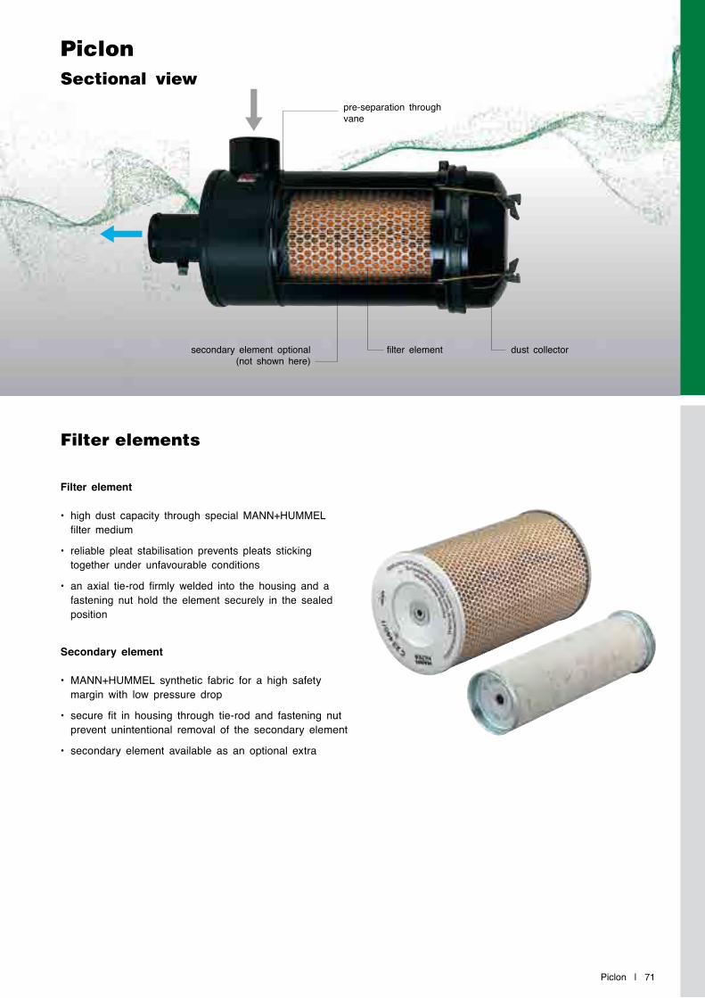
Piclon | 71
Filter element
• high dust capacity through special MANN+HUMMEL filter medium
• reliable pleat stabilisation prevents pleats sticking together under unfavourable conditions
• an axial tie-rod firmly welded into the housing and a fastening nut hold the element securely in the sealed position
Secondary element
• MANN+HUMMEL synthetic fabric for a high safety margin with low pressure drop
• secure fit in housing through tie-rod and fastening nut prevent unintentional removal of the secondary element
• secondary element available as an optional extra
PiclonSectional view
Filter elements
secondary element optional (not shown here)
pre-separation through vane
filter element dust collector
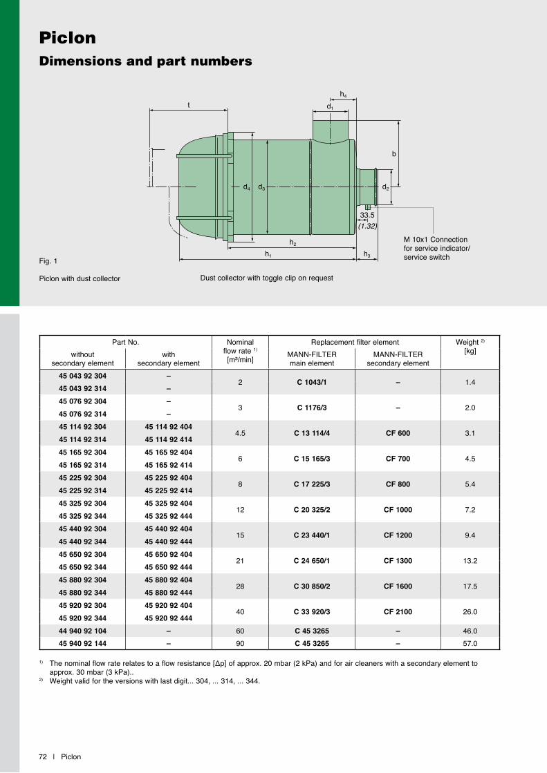
PiclonDimensions and part numbers
72 | Piclon
Fig. 1
Piclon with dust collector
b
t
d4 d3 d2
d1
h4
h2
h1 h3
1) Thenominalflowraterelatestoaflowresistance[Δp]ofapprox.20mbar(2kPa)andforaircleanerswithasecondaryelementtoapprox. 30 mbar (3 kPa)..
2) Weight valid for the versions with last digit... 304, ... 314, ... 344.
M 10x1 Connection for service indicator/service switch
33.5(1.32)
Part No. Nominal flow rate 1)
[m³/min]
Replacement filter element Weight 2)
[kg]without secondary element
withsecondary element
MANN-FILTERmain element
MANN-FILTER secondary element
45 043 92 304 –2 C 1043/1 – 1.4
45 043 92 314 –45 076 92 304 –
3 C 1176/3 – 2.045 076 92 314 –45 114 92 304 45 114 92 404
4.5 C 13 114/4 CF 600 3.145 114 92 314 45 114 92 41445 165 92 304 45 165 92 404
6 C 15 165/3 CF 700 4.545 165 92 314 45 165 92 41445 225 92 304 45 225 92 404
8 C 17 225/3 CF 800 5.445 225 92 314 45 225 92 41445 325 92 304 45 325 92 404
12 C 20 325/2 CF 1000 7.245 325 92 344 45 325 92 44445 440 92 304 45 440 92 404
15 C 23 440/1 CF 1200 9.445 440 92 344 45 440 92 44445 650 92 304 45 650 92 404
21 C 24 650/1 CF 1300 13.245 650 92 344 45 650 92 44445 880 92 304 45 880 92 404
28 C 30 850/2 CF 1600 17.545 880 92 344 45 880 92 44445 920 92 304 45 920 92 404
40 C 33 920/3 CF 2100 26.045 920 92 344 45 920 92 44444 940 92 104 – 60 C 45 3265 – 46.045 940 92 144 – 90 C 45 3265 – 57.0
Dust collector with toggle clip on request
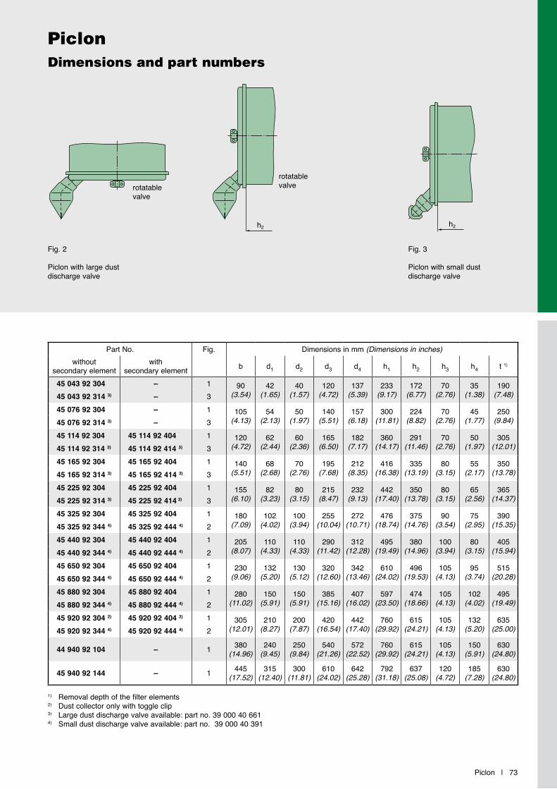
h2
h2
h2
h2
Piclon | 73
PiclonDimensions and part numbers
1) Removal depth of the filter elements2) Dust collector only with toggle clip3) Large dust discharge valve available: part no. 39 000 40 6614) Small dust discharge valve available: part no. 39 000 40 391
Fig. 2
Piclon with large dust discharge valve
Fig. 3
Piclon with small dust discharge valve
rotatable valve
rotatable valve
Part No. Fig. Dimensions in mm (Dimensions in inches)without
secondary elementwith
secondary element b d1 d2 d3 d4 h1 h2 h3 h4 t 1)
45 043 92 304 – 1 90(3.54)
42(1.65)
40(1.57)
120(4.72)
137(5.39)
233(9.17)
172(6.77)
70(2.76)
35(1.38)
190(7.48)45 043 92 314 3) – 3
45 076 92 304 – 1 105(4.13)
54(2.13)
50(1.97)
140(5.51)
157(6.18)
300(11.81)
224(8.82)
70(2.76)
45(1.77)
250(9.84)45 076 92 314 3) – 3
45 114 92 304 45 114 92 404 1 120(4.72)
62(2.44)
60(2.36)
165(6.50)
182(7.17)
360(14.17)
291(11.46)
70(2.76)
50(1.97)
305(12.01)45 114 92 314 3) 45 114 92 414 3) 3
45 165 92 304 45 165 92 404 1 140(5.51)
68(2.68)
70(2.76)
195(7.68)
212(8.35)
416(16.38)
335(13.19)
80(3.15)
55(2.17)
350(13.78)45 165 92 314 3) 45 165 92 414 3) 3
45 225 92 304 45 225 92 404 1 155(6.10)
82(3.23)
80(3.15)
215(8.47)
232(9.13)
442(17.40)
350(13.78)
80(3.15)
65(2.56)
365(14.37)45 225 92 314 3) 45 225 92 414 3) 3
45 325 92 304 45 325 92 404 1 180(7.09)
102(4.02)
100(3.94)
255(10.04)
272(10.71)
476(18.74)
375(14.76)
90(3.54)
75(2.95)
390(15.35)45 325 92 344 4) 45 325 92 444 4) 2
45 440 92 304 45 440 92 404 1 205(8.07)
110(4.33)
110(4.33)
290(11.42)
312(12.28)
495(19.49)
380(14.96)
100(3.94)
80(3.15)
405(15.94)45 440 92 344 4) 45 440 92 444 4) 2
45 650 92 304 45 650 92 404 1 230(9.06)
132(5.20)
130(5.12)
320(12.60)
342(13.46)
610(24.02)
496(19.53)
105(4.13)
95(3.74)
515(20.28)45 650 92 344 4) 45 650 92 444 4) 2
45 880 92 304 45 880 92 404 1 280(11.02)
150(5.91)
150(5.91)
385(15.16)
407(16.02)
597(23.50)
474(18.66)
105(4.13)
102(4.02)
495(19.49)45 880 92 344 4) 45 880 92 444 4) 2
45 920 92 304 2) 45 920 92 404 2) 1 305(12.01)
210(8.27)
200(7.87)
420(16.54)
442(17.40)
760(29.92)
615(24.21)
105(4.13)
132(5.20)
635(25.00)45 920 92 344 4) 45 920 92 444 4) 2
44 940 92 104 – 1 380(14.96)
240(9.45)
250(9.84)
540(21.26)
572(22.52)
760(29.92)
615(24.21)
105(4.13)
150(5.91)
630(24.80)
45 940 92 144 – 1 445(17.52)
315(12.40)
300(11.81)
610(24.02)
642(25.28)
792(31.18)
637(25.08)
120(4.72)
185(7.28)
630(24.80)
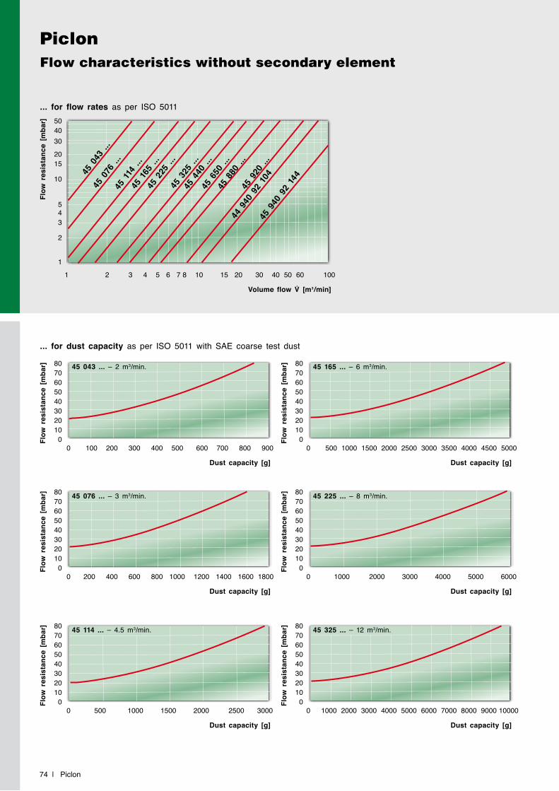
PiclonFlow characteristics without secondary element
74 | Piclon
... for flow rates as per ISO 5011
Flow
res
ista
nce
[mba
r]
Volume flow V̇ [m3/min]
45 0
43 ..
.45
076
...
45 1
14 ..
.45
165
...
45 3
25 ..
.
45 2
25 ..
.
45 6
50 ..
.45
880
...
45 9
20 ..
.
44 9
40 9
2 10
445
940
92
144
45 4
40 ..
.
1 2 3 4 5 6 7 8 10 15 20 30 40 50 60 100
504030
2015
10
543
2
1
... for dust capacity as per ISO 5011 with SAE coarse test dust
Flow
res
ista
nce
[mba
r]Fl
ow r
esis
tanc
e [m
bar]
Flow
res
ista
nce
[mba
r]
Flow
res
ista
nce
[mba
r]Fl
ow r
esis
tanc
e [m
bar]
Flow
res
ista
nce
[mba
r]
Dust capacity [g]
Dust capacity [g]
Dust capacity [g]
Dust capacity [g]
Dust capacity [g]
Dust capacity [g]
0 100 200 300 400 500 600 700 800 900
0 500 1000 1500 2000 2500 3000
0 200 400 600 800 1000 1200 1400 1600 1800
0 500 1000 1500 2000 2500 3000 3500 4000 4500 5000
0 1000 2000 3000 4000 5000 6000 7000 8000 9000 10000
0 1000 2000 3000 4000 5000 6000
80706050403020100
80706050403020100
80706050403020100
8070605040302010
0
8070605040302010
0
8070605040302010
0
45 043 ... – 2 m3/min.
45 114 ... – 4.5 m3/min.
45 076 ... – 3 m3/min.
45 165 ... – 6 m3/min.
45 325 ... – 12 m3/min.
45 225 ... – 8 m3/min.
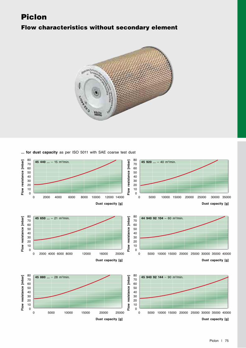
Piclon | 75
PiclonFlow characteristics without secondary element
... for dust capacity as per ISO 5011 with SAE coarse test dust
Flow
res
ista
nce
[mba
r]Fl
ow r
esis
tanc
e [m
bar]
Flow
res
ista
nce
[mba
r]
Flow
res
ista
nce
[mba
r]Fl
ow r
esis
tanc
e [m
bar]
Flow
res
ista
nce
[mba
r]
Dust capacity [g]
Dust capacity [g]
Dust capacity [g]
Dust capacity [g]
Dust capacity [g]
Dust capacity [g]
0 2000 4000 6000 8000 10000 12000 14000
0 5000 10000 15000 20000 25000
0 2000 4000 6000 8000 12000 16000 20000
0 5000 10000 15000 20000 25000 30000 35000
0 5000 10000 15000 20000 25000 30000 35000 40000
0 5000 10000 15000 20000 25000 30000 35000 40000
80706050403020100
80706050403020100
80706050403020100
8070605040302010
0
8070605040302010
0
8070605040302010
0
45 440 ... – 15 m3/min.
45 880 ... – 28 m3/min.
45 650 ... – 21 m3/min.
45 920 ... – 40 m3/min.
45 940 92 144 – 90 m3/min.
44 940 92 104 – 60 m3/min.
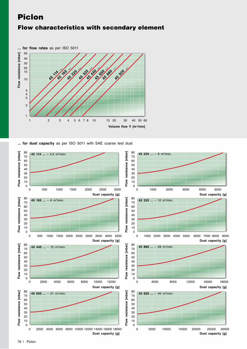
PiclonFlow characteristics with secondary element
76 | Piclon
... for flow rates as per ISO 5011
Flow
res
ista
nce
[mba
r]
Volume flow V̇ [m3/min]
45 11
4 ...
45 16
5 ...
45 2
25 ..
.
45 3
25 ..
.
45 9
20 ..
.
45 4
40 ..
.45
650
...
45 8
80 ..
.
1 2 3 4 5 6 7 8 10 15 20 30 40 50 60
5040302015
10
543
2
1
... for dust capacity as per ISO 5011 with SAE coarse test dust
Flow
res
ista
nce
[mba
r]
Dust capacity [g]0 500 1000 1500 2000 2500 3000
80706050403020100
45 114 ... – 4.5 m3/min.
Flow
res
ista
nce
[mba
r]
Dust capacity [g]0 2000 4000 6000 8000 10000 12000
80706050403020100
45 440 ... – 15 m3/min.
Flow
res
ista
nce
[mba
r]
Dust capacity [g]0 500 1000 1500 2000 2500 3000 3500 4000 4500
80706050403020100
45 165 ... – 6 m3/min.
Flow
res
ista
nce
[mba
r]
Dust capacity [g]0 2000 4000 6000 8000 10000 12000 14000 16000 18000
80706050403020100
45 650 ... – 21 m3/min.
Flow
res
ista
nce
[mba
r]
Dust capacity [g]0 1000 2000 3000 4000 5000
8070605040302010
0
45 225 ... – 8 m3/min.
Flow
res
ista
nce
[mba
r]
Dust capacity [g]0 4000 8000 12000 16000 18000
8070605040302010
0
45 880 ... – 28 m3/min.
Flow
res
ista
nce
[mba
r]
Dust capacity [g]0 5000 10000 15000 20000 25000 30000
8070605040302010
0
45 920 ... – 40 m3/min.
Flow
res
ista
nce
[mba
r]
0 1000 2000 3000 4000 5000 6000 7000 8000 9000
8070605040302010
0
45 325 ... – 12 m3/min.
Dust capacity [g]

Piclon | 77
PiclonBrackets
Fig. 2Fig. 1 Fig. 3
c
a
c
a
ff
e
bs
30° 30°30°
d
e
bs
d
e
bs
d
52(2.05)
Part No. Suitable for Fig. Dimensions in mm (Dimensions in inches) WeightPiclon
a b c d e f s[kg]
39 014 38 990 45 043 92... 1 40(1.57)
170(6.69)
130(5.12)
120(4.72)
70(2.76)
10(0.39)
2.5(0.10) 0.6
39 076 38 970 45 076 92... 1 20(0.79)
190(7.48)
150(5.91)
140(5.51)
80(3.15)
10(0.39)
3(0.12) 0.3
39 114 38 970 45 114 92... 1 20(0.79)
220(8.66)
180(7.09)
165(6.50)
100(3.94)
10(0.39)
3(0.12) 0.3
39 165 38 970 45 165 92... 1 40(1.57)
240(9.45)
200(7.87)
195(7.68)
125(4.92)
10(0.39)
3(0.12) 0.6
39 225 38 970 45 225 92... 1 40(1.57)
240(9.45)
200(7.87)
215(8.46)
130(5.12)
10(0.39)
3(0.12) 0.6
39 325 38 970 45 325 92... 1 40(1.57)
280(11.02)
240(9.45)
255(10.04)
145(5.71)
12(0.47)
3(0.12) 0.8
39 440 38 970 45 440 92... 1 40(1.57)
310(12.20)
270(10.63)
290(11.42)
165(6.50)
12(0.47)
3(0.12) 0.9
39 440 38 941 45 440 92... 3 40(1.57)
322(12.68)
270(10.63)
290(11.42)
165(6.50)
12(0.47)
3(0.12) 1.0
39 120 38 980 45 650 92... 1 40(1.57)
310(12.20)
270(10.63)
320(12.60)
185(7.28)
12(0.47)
3(0.12) 1.0
45 650 38 761 45 650 92... 3 40(1.57)
322(12.68)
270(10.63)
320(12.60)
185(7.28)
12(0.47)
3(0.12) 1.1
39 880 38 990 45 880 92... 3 40(1.57)
340(13.39)
270(10.63)
385(15.16)
220(8.66)
12(0.47)
3(0.12) 1.0
45 920 38 990 45 920 92... 2 80(3.15)
420(16.54)
380(14.96)
420(16.54)
235(9.25)
12(0.47)
3(0.12) 2.3
44 940 38 991 44 940 92... 3 40(1.57)
480(18.90)
420(16.54)
540(21.26)
284(11.18)
14(0.55)
3(0.12) 2.0
45 940 38 841 45 940 92... 3 45(1.77)
580(22.83)
520(20.47)
610(24.02)
325(12.80)
14(0.55)
3(0.12) 3.5
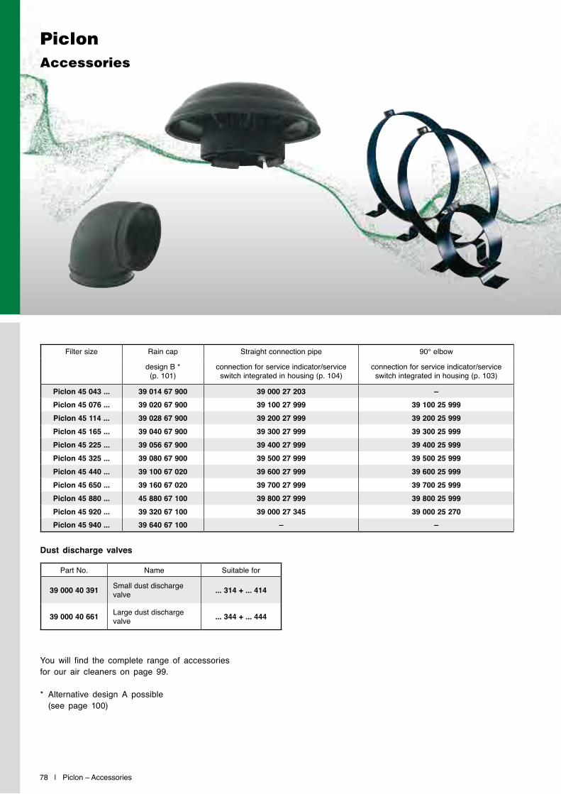
78 | Piclon – Accessories
Filter size Rain cap Straight connection pipe 90° elbow
design B *(p. 101)
connection for service indicator/service switch integrated in housing (p. 104)
connection for service indicator/service switch integrated in housing (p. 103)
Piclon 45 043 ... 39 014 67 900 39 000 27 203 –Piclon 45 076 ... 39 020 67 900 39 100 27 999 39 100 25 999Piclon 45 114 ... 39 028 67 900 39 200 27 999 39 200 25 999Piclon 45 165 ... 39 040 67 900 39 300 27 999 39 300 25 999Piclon 45 225 ... 39 056 67 900 39 400 27 999 39 400 25 999Piclon 45 325 ... 39 080 67 900 39 500 27 999 39 500 25 999Piclon 45 440 ... 39 100 67 020 39 600 27 999 39 600 25 999Piclon 45 650 ... 39 160 67 020 39 700 27 999 39 700 25 999Piclon 45 880 ... 45 880 67 100 39 800 27 999 39 800 25 999Piclon 45 920 ... 39 320 67 100 39 000 27 345 39 000 25 270Piclon 45 940 ... 39 640 67 100 – –
PiclonAccessories
You will find the complete range of accessories for our air cleaners on page 99.
* Alternative design A possible (see page 100)
Dust discharge valves
Part No. Name Suitable for
39 000 40 391 Small dust discharge valve ... 314 + ... 414
39 000 40 661 Large dust discharge valve ... 344 + ... 444
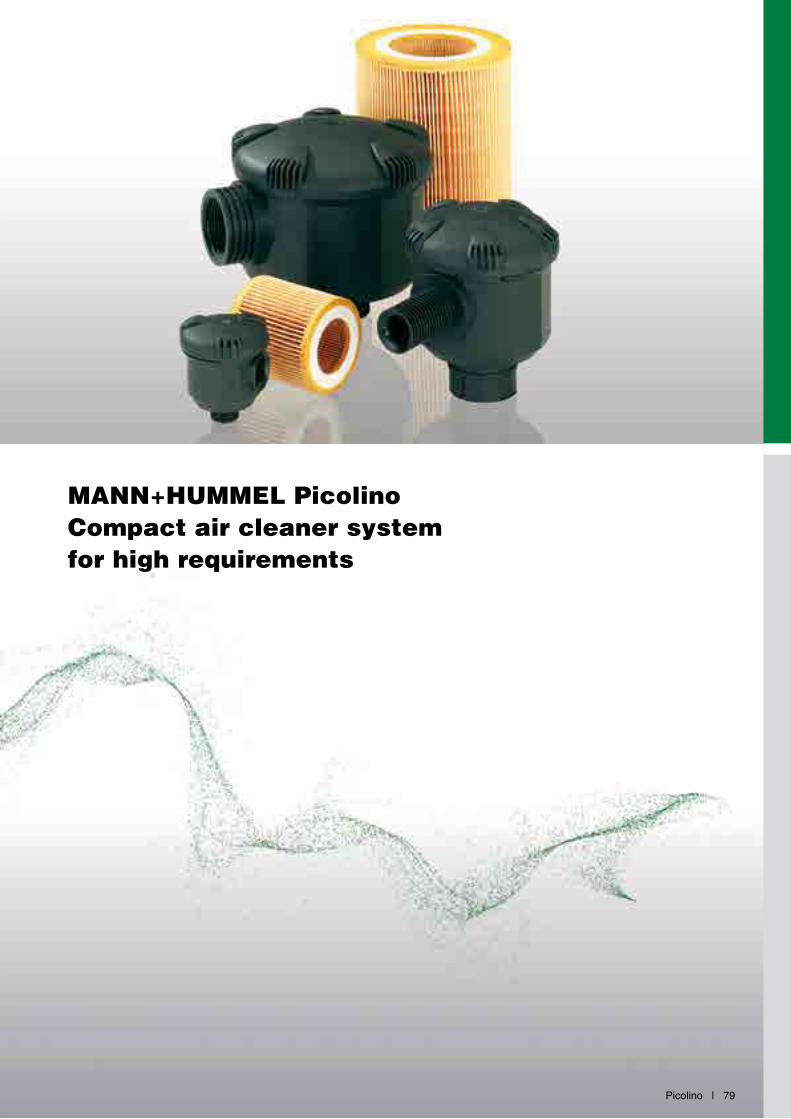
Picolino | 79
MANN+HUMMEL PicolinoCompact air cleaner system for high requirements
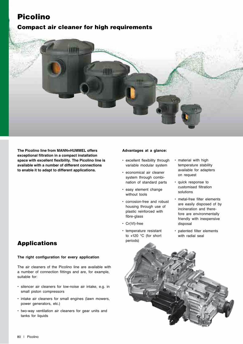
80 | Picolino
PicolinoCompact air cleaner for high requirements
The Picolino line from MANN+HUMMEL offers exceptional filtration in a compact installation space with excellent flexibility. The Picolino line is available with a number of different connections to enable it to adapt to different applications.
Advantages at a glance:
• excellent flexibility through variable modular system
• economical air cleaner system through combi-nation of standard parts
• easy element change without tools
• corrosion-free and robust housing through use of plastic reinforced with fibre-glass
• Cr(VI)-free
• temperature resistant to +120 °C (for short periods)
• material with high temperature stability available for adapters on request
• quick response to customised filtration solutions
• metal-free filter elements are easily disposed of by incineration and there-fore are environmentally friendly with inexpensive disposal
• patented filter elements with radial seal
Applications
The right configuration for every application
The air cleaners of the Picolino line are available with a number of connection fittings and are, for example, suitable for:
• silencer air cleaners for low-noise air intake, e.g. in small piston compressors
• intake air cleaners for small engines (lawn mowers, power generators, etc.)
• two-way ventilation air cleaners for gear units and tanks for liquids
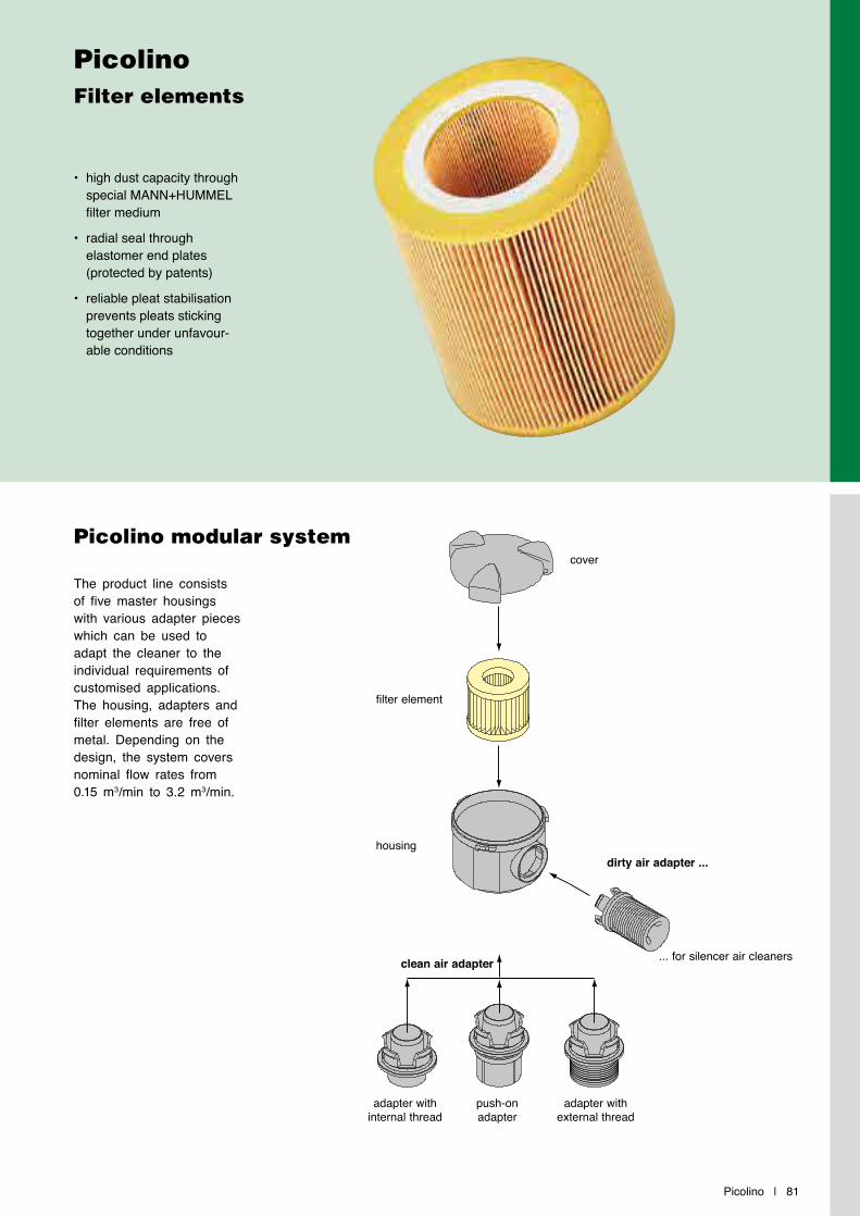
Picolino | 81
PicolinoFilter elements
Picolino modular system
• high dust capacity through special MANN+HUMMEL filter medium
• radial seal through elastomer end plates (protected by patents)
• reliable pleat stabilisation prevents pleats sticking together under unfavour-able conditions
The product line consists of five master housings with various adapter pieces which can be used to adapt the cleaner to the individual requirements of customised applications. The housing, adapters and filter elements are free of metal. Depending on the design, the system covers nominal flow rates from 0.15 m3/min to 3.2 m3/min.
cover
filter element
dirty air adapter ...
clean air adapter ... for silencer air cleaners
adapter with internal thread
push-on adapter
adapter with external thread
housing

82 | Picolino
Picolino Intake air cleaners (two-way ventilation air cleaners)Dimensions and part numbers
t
h1
h2
e1
d1 l
ø d 2
h1
t
h2
e1
d1 l
ø d 2
Part No. Fig Nominal flow rate
[m³/min] 1)
Dimensions in mm (Dimensions in inches) MANN-FILTERmain element
d1 d2 e1 h1 h2 l t
44 010 72 996 2 0.25 G ½ 3) 58(2.28)
14(0.55)
61(2.40)
34(1.34)
27(1.06)
30(1.18) C 410
44 010 72 997 2 0.2 G ⅜ 3) 58(2.28)
11(0.43)
61(2.40)
34(1.34)
27(1.06)
30(1.18) C 410
44 010 72 999 2 0.2 M 18x1.5 2) 58(2.28)
10(0.39)
61(2.40)
34(1.34)
27(1.06)
30(1.18) C 410
44 010 77 999 1 0.25 35(1.38)
58(2.28)
23(0.91)
73(2.87)
64(2.52)
27(1.06)
30(1.18) C 410
44 020 72 996 2 0.25 G ½ 3) 68(2.68)
14(0.55)
62(2.44)
34(1.34)
31(1.22)
30(1.18) C 420
44 020 72 997 2 0.25 G ⅜ 3) 68(2.68)
11(0.43)
62(2.44)
34(1.34)
31(1.22)
30(1.18) C 420
44 020 72 999 2 0.2 M 18x1.5 2) 68(2.68)
11(0.43)
62(2.44)
34(1.34)
31(1.22)
30(1.18) C 420
44 020 77 999 1 0.25 35(1.38)
68(2.68)
23(0.91)
74(2.91)
46(1.81)
31(1.22)
30(1.18) C 420
44 030 72 999 2 0.8 G ¾ 3) 102(4.02)
15(0.59)
94(3.70)
45(1.77)
48(1.89)
68(2.68) C 630
44 030 77 997 1 1.2 40(1.57)
102(4.02)
25(0.98)
116(4.57)
67(2.64)
48(1.89)
68(2.68) C 630
44 030 77 998 1 1.2 30(1.18)
102(4.02)
23(0.91)
116(4.57)
67(2.64)
48(1.89)
68(2.68) C 630
Fig. 1 Fig. 2
1) The nominal flow rate relates to flow resistance of 15 mbar. The flow rate depends on the cross-section of the clean air outlet.2) External thread3) Internal thread
Cover Cover

Picolino | 83
Picolino Intake air cleaners (two-way ventilation air cleaners)Dimensions and part numbers
t
h1
h2
e1
d1 l
ø d 2
h1
t
h2
e1
d1 l
ø d 2
Part No. Fig. Nominal flow rate
[m³/min] 1)
Dimensions in mm (Dimensions in inches) MANN-FILTERmain element
d1 d2 e1 h1 h2 l t
44 030 77 999 1 0.7 20(0.79)
102(4.02)
23(0.91)
116(4.57)
67(2.64)
48(1.89)
68(2.68) C 630
44 040 72 999 2 2.1 G 1¼ 3) 145(5.71)
19(0.75)
131(5.16)
71(2.80)
69(2.72)
79(3.11) C 1140
44 040 77 996 1 3.0 71(2.8)
145(5.71)
25(0.98)
136(5.35)
76(2.99)
69(2.72)
79(3.11) C 1140
44 040 77 997 1 2.8 60(2.36)
145(5.71)
25(0.98)
136(5.35)
76(2.99)
69(2.72)
79(3.11) C 1140
44 040 77 998 1 2.6 52(2.05)
145(5.71)
25(0.98)
136(5.35)
76(2.99)
69(2.72)
79(3.11) C 1140
44 040 77 999 1 2.1 40(1.57)
145(5.71)
25(0.98)
136(5.35)
76(2.99)
69(2.72)
79(3.11) C 1140
44 050 72 999 2 2.3 G 1¼ 3) 181(7.13)
19(0.75)
188(7.40)
112(4.41)
86(3.39)
135(5.32) C 1250
44 050 77 996 1 3.5 71(2.8)
181(7.13)
25(0.98)
193(7.60)
117(4.61)
86(3.39)
135(5.32) C 1250
44 050 77 997 1 3.4 60(2.36)
181(7.13)
25(0.98)
193(7.60)
117(4.61)
86(3.39)
135(5.32) C 1250
44 050 77 998 1 3.1 52(2.05)
181(7.13)
25(0.98)
193(7.60)
117(4.61)
86(3.39)
135(5.32) C 1250
44 050 77 999 1 2.3 40(1.57)
181(7.13)
25(0.98)
193(7.60)
117(4.61)
86(3.39)
135(5.32) C 1250
Fig. 1 Fig. 2
1) The nominal flow rate relates to flow resistance of 15 mbar. The flow rate depends on the cross-section of the clean air outlet.2) External thread3) Internal thread
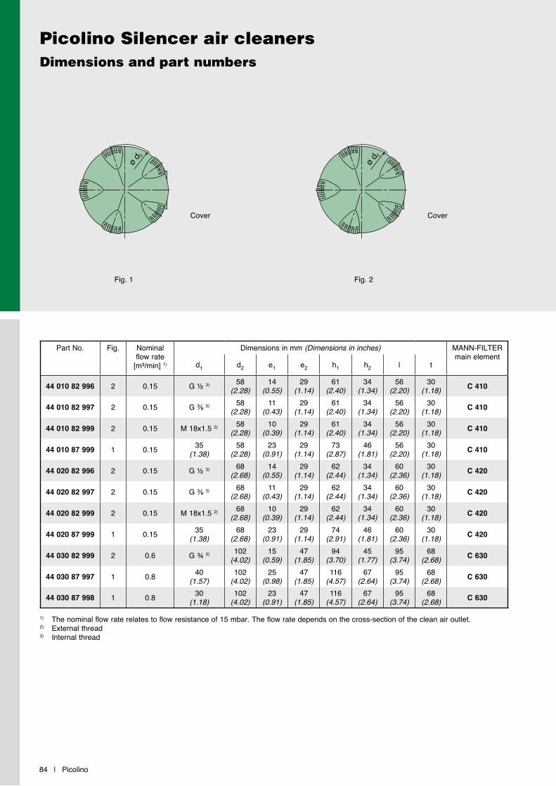
84 | Picolino
Picolino Silencer air cleanersDimensions and part numbers
Part No. Fig. Nominal flow rate
[m³/min] 1)
Dimensions in mm (Dimensions in inches) MANN-FILTERmain element
d1 d2 e1 e2 h1 h2 l t
44 010 82 996 2 0.15 G ½ 3) 58(2.28)
14(0.55)
29(1.14)
61(2.40)
34(1.34)
56(2.20)
30(1.18) C 410
44 010 82 997 2 0.15 G ⅜ 3) 58(2.28)
11(0.43)
29(1.14)
61(2.40)
34(1.34)
56(2.20)
30(1.18) C 410
44 010 82 999 2 0.15 M 18x1.5 2) 58(2.28)
10(0.39)
29(1.14)
61(2.40)
34(1.34)
56(2.20)
30(1.18) C 410
44 010 87 999 1 0.15 35(1.38)
58(2.28)
23(0.91)
29(1.14)
73(2.87)
46(1.81)
56(2.20)
30(1.18) C 410
44 020 82 996 2 0.15 G ½ 3) 68(2.68)
14(0.55)
29(1.14)
62(2.44)
34(1.34)
60(2.36)
30(1.18) C 420
44 020 82 997 2 0.15 G ⅜ 3) 68(2.68)
11(0.43)
29(1.14)
62(2.44)
34(1.34)
60(2.36)
30(1.18) C 420
44 020 82 999 2 0.15 M 18x1.5 2) 68(2.68)
10(0.39)
29(1.14)
62(2.44)
34(1.34)
60(2.36)
30(1.18) C 420
44 020 87 999 1 0.15 35(1.38)
68(2.68)
23(0.91)
29(1.14)
74(2.91)
46(1.81)
60(2.36)
30(1.18) C 420
44 030 82 999 2 0.6 G ¾ 3) 102(4.02)
15(0.59)
47(1.85)
94(3.70)
45(1.77)
95(3.74)
68(2.68) C 630
44 030 87 997 1 0.8 40(1.57)
102(4.02)
25(0.98)
47(1.85)
116(4.57)
67(2.64)
95(3.74)
68(2.68) C 630
44 030 87 998 1 0.8 30(1.18)
102(4.02)
23(0.91)
47(1.85)
116(4.57)
67(2.64)
95(3.74)
68(2.68) C 630
h1
h2
e1
d1 l
t
ø d 2
h1
h2
e1
d1 l
t
ø d 2
Fig. 1 Fig. 2
Cover Cover
1) The nominal flow rate relates to flow resistance of 15 mbar. The flow rate depends on the cross-section of the clean air outlet.2) External thread3) Internal thread
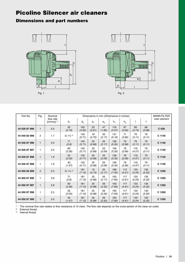
Picolino | 85
Picolino Silencer air cleanersDimensions and part numbers
Part No. Fig. Nominal flow rate
[m³/min] 1)
Dimensions in mm (Dimensions in inches) MANN-FILTERmain element
d1 d2 e1 e2 h1 h2 l t
44 030 87 999 1 0.5 20(0.79)
102(4.02)
23(0.91)
47(1.85)
116(4.57)
67(2.64)
95(3.74)
68(2.68) C 630
44 040 82 999 2 1.7 G 1¼ 3) 145(5.71)
19(0.75)
55(2.17)
131(5.16)
71(2.80)
79(3.11)
79(3.11) C 1140
44 040 87 996 1 2.0 71(2.8)
145(5.71)
25(0.98)
55(2.17)
136(5.35)
76(2.99)
79(3.11)
79(3.11) C 1140
44 040 87 997 1 2.0 60(2.36)
145(5.71)
25(0.98)
53(2.09)
136(5.35)
76(2.99)
116(4.57)
79(3.11) C 1140
44 040 87 998 1 1.9 52(2.05)
145(5.71)
25(0.98)
53(2.09)
136(5.35)
76(2.99)
116(4.57)
79(3.11) C 1140
44 040 87 999 1 1.6 40(1.57)
145(5.71)
25(0.98)
53(2.09)
136(5.35)
76(2.99)
116(4.57)
79(3.11) C 1140
44 050 82 999 2 2.0 G 1¼ 3) 181(7.13)
19(0.75)
55(2.17)
188(7.40)
112(4.41)
133(5.24)
135(5.32) C 1250
44 050 87 996 1 2.8 71(2.8)
181(7.13)
25(0.98)
55(2.17)
193(7.60)
117(4.61)
133(5.24)
135(5.32) C 1250
44 050 87 997 1 2.8 60(2.36)
181(7.13)
25(0.98)
59(2.32)
193(7.60)
117(4.61)
133(5.24)
135(5.32) C 1250
44 050 87 998 1 2.5 52(2.05)
181(7.13)
25(0.98)
59(2.32)
193(7.60)
117(4.61)
133(5.24)
135(5.32) C 1250
44 050 87 999 1 2.0 40(1.57)
181(7.13)
25(0.98)
59(2.32)
193(7.60)
117(4.61)
133(5.24)
135(5.32) C 1250
1) The nominal flow rate relates to flow resistance of 15 mbar. The flow rate depends on the cross-section of the clean air outlet.2) External thread3) Internal thread
h1
h2
e1
d1 l
t ø d 2
h1
h2
e1
d1 l
t
ø d 2
Fig. 1 Fig. 2

86 | Picolino
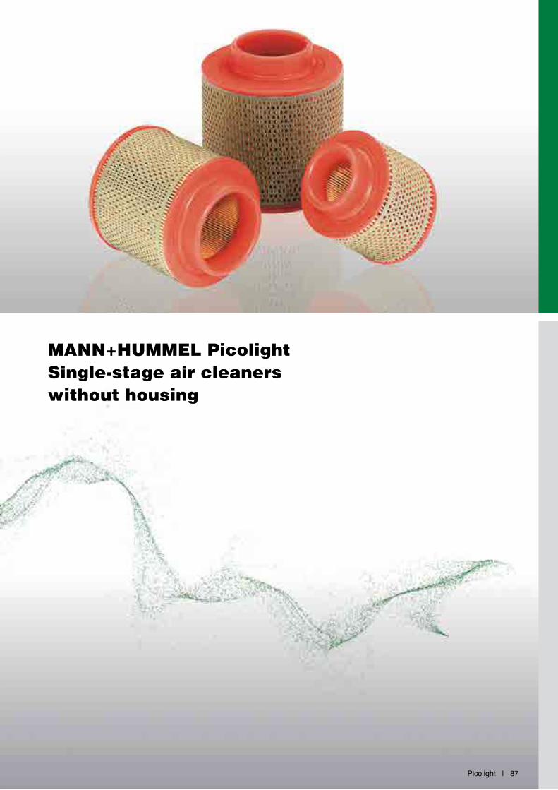
Picolight | 87
MANN+HUMMEL PicolightSingle-stage air cleaners without housing
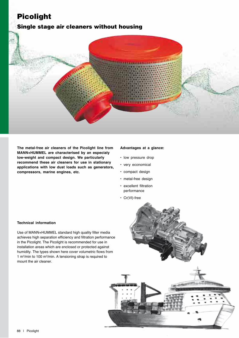
88 | Picolight
PicolightSingle stage air cleaners without housing
The metal-free air cleaners of the Picolight line from MANN+HUMMEL are characterised by an especialy low-weight and compact design. We particularly recommend these air cleaners for use in stationary applications with low dust loads such as generators, compressors, marine engines, etc.
Advantages at a glance:
• low pressure drop
• very economical
• compact design
• metal-free design
• excellent filtration performance
• Cr(VI)-free
Technical information
Use of MANN+HUMMEL standard high quality filter media achieves high separation efficiency and filtration performance in the Picolight. The Picolight is recommended for use in installation areas which are enclosed or protected against humidity. The types shown here cover volumetric flows from 1 m3/min to 100 m3/min. A tensioning strap is required to mount the air cleaner.

Picolight | 89
PicolightDimensions and part numbers
MANN-FILTER Nominal flow rate1)
[m3/min]
Dimensions in mm (Dimensions in inches) Weight[kg]
Tighteningstrap
d1 d2 d3 h1 h2 e
C 1131 3.3 50(1.97)
65(2.56)
110(4.33)
120(4.72)
95(3.74)
20(0.79) 0.16 02 018 01 709
C 1368 6.8 76(2.99)
90(3.54)
130(5.12)
150(5.91)
125(4.92)
20(0.79) 0.24 02 018 01 712
C 17 100 7.7 76(2.99)
90(3.54)
160(6.30)
165(6.50)
140(5.51)
25(0.98) 0.38 02 018 01 712
C 23 174 12.5 100(3.94)
120(4.72)
230(9.06)
156(6.14)
120(4.72)
30(1.18) 0.68 02 018 01 715
C 31 1195 40 198(7.8)
198(7.8)
318(12.52)
444(17.48)
400(15.75)
40(1.57) 3.3 02 018 01 724
C 31 1195/1 40 198(7.8)
198(7.8)
318(12.52)
444(17.48)
400(15.75)
40(1.57) 3.2 02 018 01 724
C 43 1090/1 80 250(9.84)
260(10.24)
425(16.73)
404(15.91)
335(13.19)
80(3.15) 5.6 02 018 01 728
d3
d2d1
h2h1
1) The nominal flow rate relates to flow resistance of 10 mbar.
e
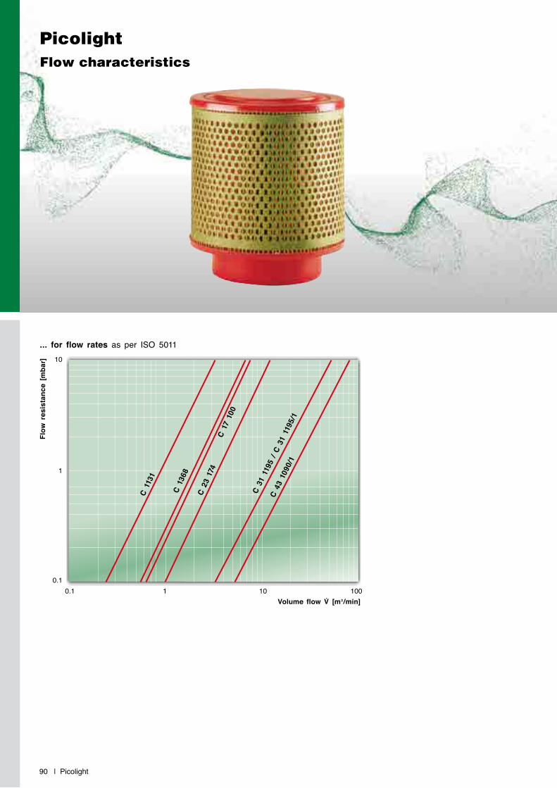
... for flow rates as per ISO 5011
Flow
res
ista
nce
[mba
r]
Volume flow V̇ [m3/min]
C 13
68
C 11
31
C 23
174
C 43
109
0/1
C 17
100
C 31
119
5 / C
31
1195
/1
0.1 1 10 100
10
1
0.1
90 | Picolight
PicolightFlow characteristics
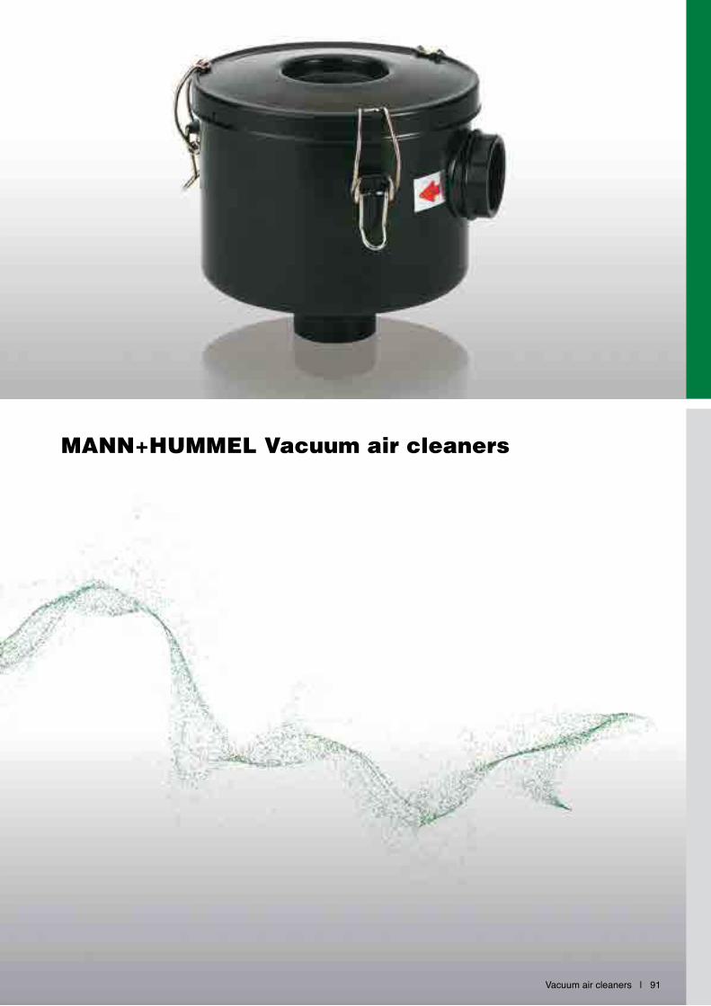
Vacuum air cleaners | 91
MANN+HUMMEL Vacuum air cleaners
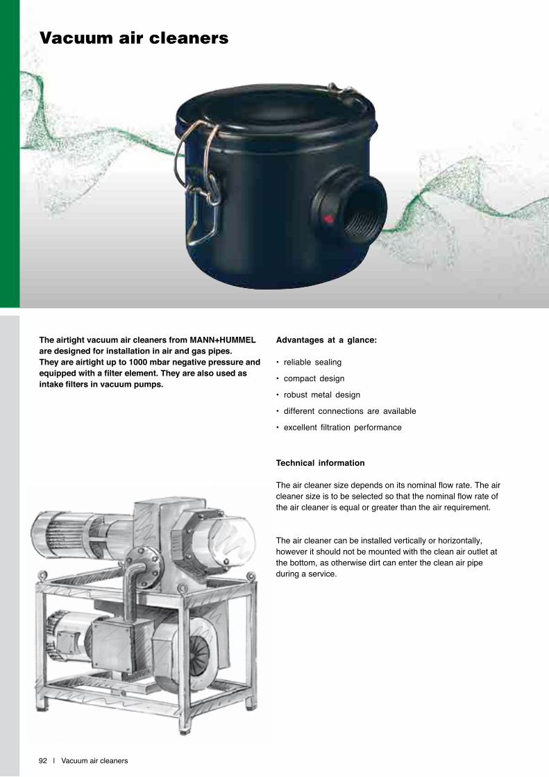
92 | Vacuum air cleaners
Vacuum air cleaners
The airtight vacuum air cleaners from MANN+HUMMEL are designed for installation in air and gas pipes. They are airtight up to 1000 mbar negative pressure and equipped with a filter element. They are also used as intake filters in vacuum pumps.
Advantages at a glance:
• reliable sealing
• compact design
• robust metal design
• different connections are available
• excellent filtration performance
Technical information
The air cleaner size depends on its nominal flow rate. The air cleaner size is to be selected so that the nominal flow rate of the air cleaner is equal or greater than the air requirement.
The air cleaner can be installed vertically or horizontally, however it should not be mounted with the clean air outlet at the bottom, as otherwise dirt can enter the clean air pipe during a service.
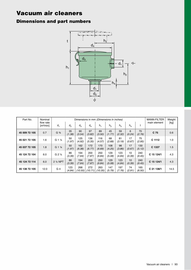
Vacuum air cleaners | 93
Vacuum air cleanersDimensions and part numbers
Part No. Nominal flow rate[m³/min]
Dimensions in mm (Dimensions in inches) MANN-FILTERmain element
Weight[kg]
d1 d2 d3 d4 h1 h2 h3 h4 t
45 009 72 105 0.7 G ¾ 35(1.38)
90(3.54)
97(3.82)
89(3.50)
45(1.77)
59(2.32)
6(0.24)
70(2.76) C 75 0.6
45 021 72 105 1.6 G 1 ¼ 50(1.97)
125(4.92)
136(5.35)
116(4.57)
68(2.68)
81(3.19)
17(0.67)
75(2.95) C 1112 1.0
45 037 72 105 1.8 G 1 ¼ 50(1.97)
162(6.38)
172(6.77)
170(6.69)
108(4.25)
98(3.86)
17(0.67)
130(5.12) C 1337 1.5
45 124 72 104 6.0 G 2 ½ 86(3.39)
194(7.64)
200(7.87)
250(9.84)
129(5.08)
123(4.84)
10(0.39)
240(9.45) C 15 124/1 4.3
45 124 72 114 6.0 2 ½ NPT 86(3.39)
194(7.64)
200(7.87)
250(9.84)
129(5.08)
123(4.84)
10(0.39)
240(9.45) C 15 124/1 4.3
45 138 72 105 12.0 G 4 123(4.84)
268(10.55)
272(10.71)
263(10.35)
147(5.79)
197(7.76)
74(2.91)
165(6.50) C 21 138/1 14.5
d1
h2
h4d1d2
h1
d4h3
d3
t

94 | Vacuum air cleaners
Vacuum air cleanersFlow characteristics
... for flow rates as per ISO 5011
Flow
res
ista
nce
[mba
r]
Volume flow V̇ [m3/min]
0.2 0.3 0.5 1 2 3 4 5 10 20
5040
30
20
10
5
1
45 0
21 7
2 ...
45 0
09 7
2 ...
45 1
24 7
2 ...
45 0
37 7
2 ...
45 1
38 7
2 ...
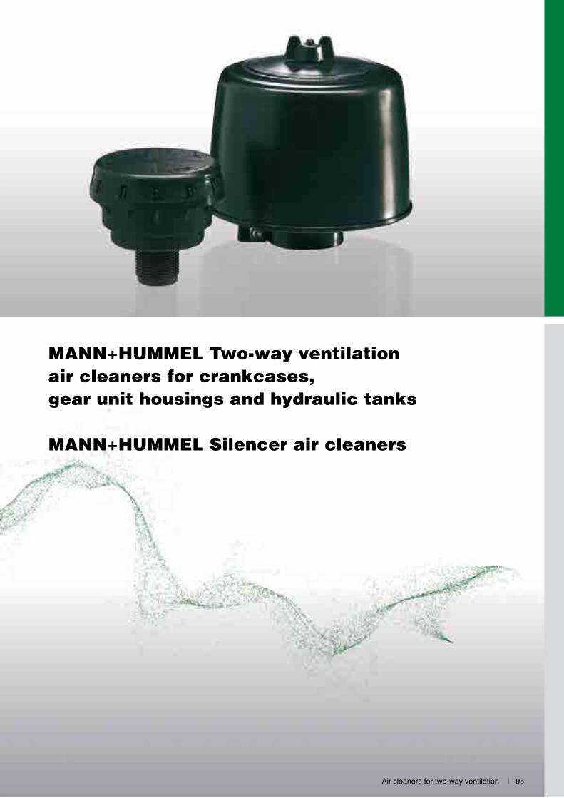
Air cleaners for two-way ventilation | 95
MANN+HUMMEL Two-way ventilation air cleaners for crankcases, gear unit housings and hydraulic tanks
MANN+HUMMEL Silencer air cleaners
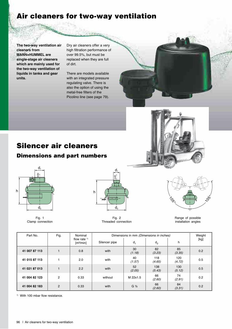
Air cleaners for two-way ventilation
The two-way ventilation air cleaners from MANN+HUMMEL are single-stage air cleaners which are mainly used for the two-way ventilation of liquids in tanks and gear units.
Dry air cleaners offer a very high filtration performance of over 99.5%, but must be replaced when they are full of dirt.
There are models available with an integrated pressure regulating valve. There is also the option of using the metal-free filters of the Picolino line (see page 79).
Fig. 1Clamp connection
Fig. 2Threaded connection
Range of possible installation angles
d1
h
d2
h
d1
d2105°105°
Silencer air cleaners Dimensions and part numbers
Part No. Fig. Nominal flow rate 1)
[m³/min]
Dimensions in mm (Dimensions in inches) Weight [kg]
Silencer pipe d1 d2 h
41 007 87 113 1 0.8 with 30(1.18)
82(3.23)
85(3.35) 0.2
41 015 87 113 1 2.0 with 40(1.57)
118(4.65)
120(4.72) 0.5
41 021 87 013 1 2.2 with 52(2.05)
138(5.43)
130(5.12) 0.5
41 004 82 123 2 0.33 without M 22x1.5 66(2.60)
74(2.91) 0.2
41 004 82 183 2 0.33 with G ½ 66(2.60)
84(3.31) 0.2
1) With 100 mbar flow resistance.
96 | Air cleaners for two-way ventilation

Two-way ventilation air cleaners (dry air cleaners)Dimensions and part numbers
Fig. 1 Fig. 2 Fig. 3
h
d1
d2
h
d1
d2
h
d1
d2
h
d1
d2
h
d1
d2
h
d1
d2
h
d1
d2
h
d1
d2
h
d1
d2
1) The entire air cleaner is exchanged during a service.2) With integrated pressure regulating valve.
Part No. Fig. Nominal flow rate[m³/min]
Opening pressure Dimensions in mm (Dimensions in inches)
MANN-FILTERmain element
Weight [kg]
[bar] [kPa] d1 d2 h
45 001 62 185 1 – – – M 18x1.5 45(1.77)
47(1.85)
–1) 0.08
45 003 65 900 2 – – – 35(1.38)
80(3.15)
65(2.56)
–1) 0.06
45 003 62 902 2 – – – G ¾ 80(3.15)
73.5(2.89)
–1) 0.08
45 003 62 900 2) 2 0.2 0.85 85 G ¾ 80(3.15)
73.5(2.89)
–1) 0.1
45 003 62 901 2) 2 0.2 0.35 35 G ¾ 80(3.15)
73.5(2.89)
–1) 0.1
45 009 77 106 3 0.5 – – 20(0.79)
98(3.86)
110(4.33) C 75/4 0.3
45 021 77 125 3 2.0 – – 40(1.57)
132(5.20)
120(4.72) C 1112 0.5
45 032 77 105 3 3.5 – – 52(2.05)
132(5.20)
152(5.98) C 1132 0.65
45 037 77 015 3 4.5 – – 60(2.36)
170(6.69)
175(6.89) C 1337 1.1
45 074 77 115 3 8.0 – – 80(3.15)
208(8.19)
185(7.28) C 1574 1.3
45 138 77 126 3 15.0 – – 100(3.94)
283(11.14)
200(7.87) C 21 138/1 7.0
45 240 77 104 3 23.0 – – 140(5.51)
318(12.52)
302(11.89) C 26 240 9.0
45 375 77 104 3 32.0 – – 180(7.09)
396(15.59)
285(11.22) C 30 375 11.0
Air cleaners for two-way ventilation | 97
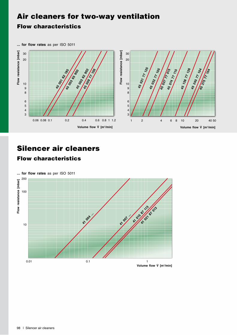
98 | Silencer air cleaners
Silencer air cleanersFlow characteristics
... for flow rates as per ISO 5011
Flow
res
ista
nce
[mba
r]
Volume flow V̇ [m3/min]0.01 0.1 1
200
100
10
... for flow rates as per ISO 5011
Flow
res
ista
nce
[mba
r]
Volume flow V̇ [m3/min]
45 0
01 6
2 18
545
003
65
900
45 0
03 6
2 90
245
009
77
106
45 0
21 7
7 12
545
032
77
105
45 0
37 7
7 01
545
074
77
115
45 1
38 7
7 12
645
240
77
104
45 3
75 7
7 10
4
0.06 0.08 0.1 0.2 0.4 0.6 0.8 1 1.2Fl
ow r
esis
tanc
e [m
bar]
Volume flow V̇ [m3/min]
1 2 4 6 8 10 20 40 50
30
20
1098
6543
30
20
1098
6543
Air cleaners for two-way ventilationFlow characteristics
41 0
07 ..
.
41 0
04 ..
.
41 0
15 8
7 11
341
021
87
013

Accessories | 99
MANN+HUMMEL Accessories for air cleaners
The reliable operation of intake air cleaners for internal combustion engines and compressors must also be ensured under the most difficult operating conditions. This is only possible if the air cleaner and the accessories are perfectly matched to each other.
MANN+HUMMEL offers a comprehensive range of accessories for all air cleaners especially designed for the respective type of air cleaner. These are proven products which offer reliability and long life in numerous applications – also under the hardest oper-ating conditions.
Rain caps Page 100Protect against ingress of water and coarse dirt particles
Precleaners Page 102Extend the service life of single-stage air cleaners
Air connecting parts Page 103For the secure connection of the air cleaner to the engine or compressor
Ejectors Page 111For the maintenance-free scavenging of precleaners and two-stage air cleaners
Service switches / indicator Page 113Provide an electrical indication when a filter service is required
Service indicators Page 117Indicate via a display when a filter service is required

100 | Rain caps
Rain caps – Design A
In order to effectively prevent ingress of rain, snow, spray water etc. MANN+HUMMEL recommends equipping the air cleaner with a rain cap. Since this also protects the air cleaner against coarse contaminant particles, the main element is less exposed to damage and this extends the service interval.
e = insertion depth
ee
hh
d1
d1
d2
d2
Part No. Suitable for Dimensions in mm (Dimensions in inches) Weigh[kg]
Europiclon NLG Piclon ENTARON XD d1 d2 e h
39 014 67 910 1) 45 050 ... – 45 043 ... – 45(1.77)
150(5.91)
22(0.87)
63(2.48) 0.11
39 020 67 910 1) 45 100 ... – 45 076 ... – 54(2.13)
150(5.91)
22(0.87)
63(2.48) 0.11
39 028 67 910 1) 45 200 ... – 45 114 ... – 62(2.44)
150(5.91)
22(0.87)
63(2.48) 0.11
39 040 67 910 1) 45 300 ... – 45 165 ... – 68(2.68)
200(7.87)
30(1.18)
85(3.35) 0.23
39 056 67 910 1) 45 400 ... – 45 225 ... – 82(3.23)
200(7.87)
30(1.18)
85(3.35) 0.23
39 080 67 910 1) 45 500 ... – 45 325 ... – 102(4.02)
270(10.63)
40(1.57)
115(4.53) 0.44
39 100 67 910 1) 45 600 ... – 45 440 ... – 110(4.33)
270(10.63)
40(1.57)
115(4.53) 0.44
39 160 67 910 1) 45 700 ... NLG 15 - ... 45 650 ... XD 14/17 132(5.20)
360(14.17)
50(1.97)
150(5.91) 0.90
39 190 67 910 1) 45 800 ... NLG 21 - ... 45 880 ... XD 21 150(5.91)
360(14.17)
50(1.97)
150(5.91) 0.90
39 220 67 910 1) – NLG 28 - ... – XD 28 180(7.09)
405(15.94)
33(1.30)
128(5.04) 0.95
39 370 67 910 1) – NLG 37 - ... 45 920 ... – 210(8.27)
535(21.06)
42(1.56)
126(4.96) 1.80
1) Plastic model, Cr(VI)-free
Rain caps | 101
Rain caps – Design B
e = insertion depth
ee
hh
d1
d1
d2
d2
Part No. Suitable for Dimensions in mm (Dimensions in inches) Weigh[kg]
Europiclon NLG Piclon ENTARON XD d1 d2 e h
39 014 67 900 1) 45 050 ... – 45 043 ... – 45(1.77)
92(3.62)
22(0.87)
53(2.09) 0.07
39 020 67 900 1) 45 100 ... – 45 076 ... – 54(2.13)
110(4.33)
22(0.87)
53(2.09) 0.08
39 028 67 900 1) 45 200 ... – 45 114 ... – 62(2.44)
124(4.88)
22(0.87)
56(2.20) 0.11
39 040 67 900 1) 45 300 ... – 45 165 ... – 68(2.68)
145(5.71)
22(0.87)
63(2.48) 0.12
39 056 67 900 1) 45 400 ... – 45 225 ... – 82(3.23)
172(6.77)
22(0.87)
64(2.52) 0.15
39 080 67 900 1) 45 500 ... – 45 325 ... – 102(4.02)
203(7.99)
35(1.38)
90(3.54) 0.18
39 100 67 020 2) 45 600 ... – 45 440 ... – 110(4.33)
236(9.29)
40(1.57)
125(4.92) 0.82
39 160 67 020 2) 45 700 ... NLG 15 - ... 45 650 ... XD 14/17 132(5.20)
292(11.50)
40(1.57)
138(5.43) 1.50
45 880 67 100 2) 45 800 ... NLG 21 - ... 45 880 ... XD 21 150(5.91)
342(13.46)
40(1.57)
166(6.54) 2.00
39 220 67 100 2) – NLG 28 - ... – XD 28 180(7.09)
342(13.46)
45(1.77)
163(6.42) 2.20
39 320 67 100 – – 45 920 ... – 210(8.27)
455(17.91)
80(3.15)
223(8.78) 2.50
39 640 67 100 2) – – 45 940 ... – 315(12.40)
645(25.39)
86(3.39)
272(10.71) 5.80
1) Plastic model, Cr(VI)-free2) Metal model
The rain caps are simply pushed on to the dirty air connection of the air cleaner or onto the air intake of the dirty air pipe and then fastened using the tightening strap supplied. In order to cater for different installation requirements and styling, the rain caps are available in two different versions.
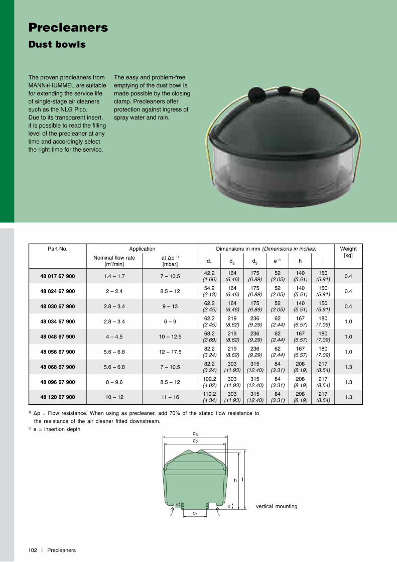
102 | Precleaners
PrecleanersDust bowls
The proven precleaners from MANN+HUMMEL are suitable for extending the service life of single-stage air cleaners such as the NLG Pico. Due to its transparent insert. it is possible to read the filling level of the precleaner at any time and accordingly select the right time for the service.
The easy and problem-free emptying of the dust bowl is made possible by the closing clamp. Precleaners offer protection against ingress of spray water and rain.
Part No. Application Dimensions in mm (Dimensions in inches) Weight[kg]Nominal flow rate
[m3/min]at Δp 1)
[mbar] d1 d2 d3 e 2) h l
48 017 67 900 1.4 – 1.7 7 – 10.5 42.2(1.66)
164(6.46)
175(6.89)
52(2.05)
140(5.51)
150(5.91) 0.4
48 024 67 900 2 – 2.4 8.5 – 12 54.2(2.13)
164(6.46)
175(6.89)
52(2.05)
140(5.51)
150(5.91) 0.4
48 030 67 900 2.8 – 3.4 9 – 13 62.2(2.45)
164(6.46)
175(6.89)
52(2.05)
140(5.51)
150(5.91) 0.4
48 034 67 900 2.8 – 3.4 6 – 9 62.2(2.45)
219(8.62)
236(9.29)
62(2.44)
167(6.57)
180(7.09) 1.0
48 048 67 900 4 – 4.5 10 – 12.5 68.2(2.69)
219(8.62)
236(9.29)
62(2.44)
167(6.57)
180(7.09) 1.0
48 056 67 900 5.6 – 6.8 12 – 17.5 82.2(3.24)
219(8.62)
236(9.29)
62(2.44)
167(6.57)
180(7.09) 1.0
48 068 67 900 5.6 – 6.8 7 – 10.5 82.2(3.24)
303(11.93)
315(12.40)
84(3.31)
208(8.19)
217(8.54) 1.3
48 096 67 900 8 – 9.6 8.5 – 12 102.2(4.02)
303(11.93)
315(12.40)
84(3.31)
208(8.19)
217(8.54) 1.3
48 120 67 900 10 – 12 11 – 16 110.2(4.34)
303(11.93)
315(12.40)
84(3.31)
208(8.19)
217(8.54) 1.3
1) Δp = Flow resistance. When using as precleaner. add 70% of the stated flow resistance to the resistance of the air cleaner fitted downstream.
2) e = insertion depth
vertical mounting
d2
d1
d3
e
h l
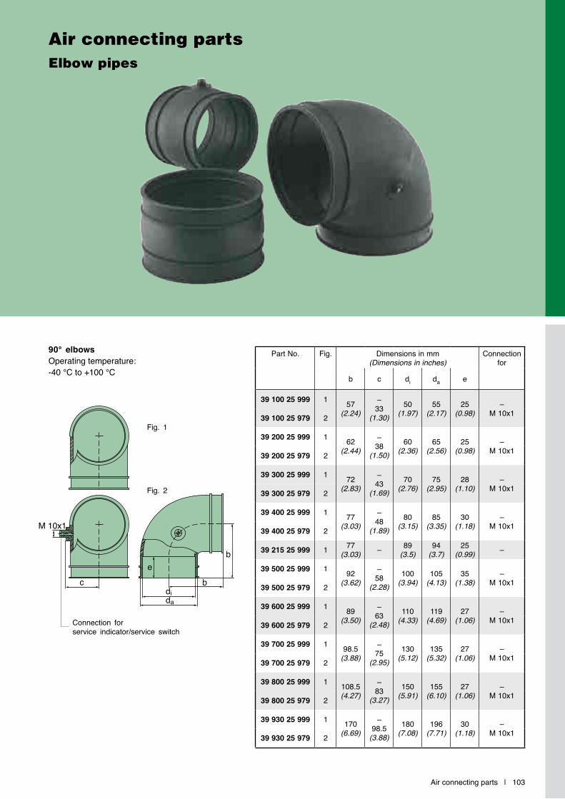
Air connecting parts | 103
M 10x1
c
eb
dida
b
Air connecting partsElbow pipes
90° elbowsOperating temperature:-40 °C to +100 °C
Connection for service indicator/service switch
Fig. 1
Fig. 2
Part No. Fig. Dimensions in mm (Dimensions in inches)
Connection for
b c di da e
39 100 25 999 1 57(2.24)
–33
(1.30)50
(1.97)55
(2.17)25
(0.98)–
M 10x139 100 25 979 2
39 200 25 999 1 62(2.44)
–38
(1.50)60
(2.36)65
(2.56)25
(0.98)–
M 10x139 200 25 979 2
39 300 25 999 1 72(2.83)
–43
(1.69)70
(2.76)75
(2.95)28
(1.10)–
M 10x139 300 25 979 2
39 400 25 999 1 77(3.03)
–48
(1.89)80
(3.15)85
(3.35)30
(1.18)–
M 10x139 400 25 979 2
39 215 25 999 1 77(3.03) – 89
(3.5)94
(3.7)25
(0.99) –
39 500 25 999 1 92(3.62)
–58
(2.28)100
(3.94)105
(4.13)35
(1.38)–
M 10x139 500 25 979 2
39 600 25 999 1 89(3.50)
–63
(2.48)110
(4.33)119
(4.69)27
(1.06)–
M 10x139 600 25 979 2
39 700 25 999 1 98.5(3.88)
–75
(2.95)130
(5.12)135
(5.32)27
(1.06)–
M 10x139 700 25 979 2
39 800 25 999 1 108.5(4.27)
–83
(3.27)150
(5.91)155
(6.10)27
(1.06)–
M 10x139 800 25 979 2
39 930 25 999 1 170(6.69)
–98.5
(3.88)180
(7.08)196
(7.71)30
(1.18)–
M 10x139 930 25 979 2
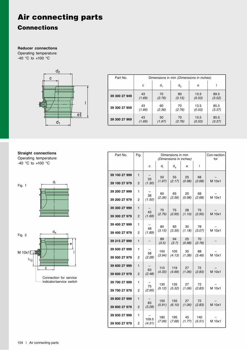
104 | Air connecting parts
Air connecting partsConnections
Connection for service indicator/service switch
Fig. 1
Fig. 2
Straight connectionsOperating temperature: -40 °C to +100 °C
Reducer connectionsOperating temperature: -40 °C to +100 °C
di
l
e
da
c
l1/2
M 10x1
di
l
e
da
c
l1/2
M 10x1
e
l
d1
d2
c Part No. Dimensions in mm (Dimensions in inches)
c d1 d2 e l
39 300 27 949 43(1.69)
70(2.76)
80(3.15)
13.5(0.53)
89.5(3.52)
39 300 27 959 43(1.69)
60(2.36)
70(2.76)
13.5(0.53)
85.5(3.37)
39 300 27 969 43(1.69)
50(1.97)
70(2.76)
13.5(0.53)
85.5(3.37)
Part No. Fig. Dimensions in mm (Dimensions in inches)
Con-nection for
c di da e l
39 100 27 999 1 –33
(1.30)50
(1.97)55
(2.17)25
(0.98)68
(2.68)–
M 10x139 100 27 979 2
39 200 27 999 1 –38
(1.50)60
(2.36)65
(2.56)25
(0.98)68
(2.68)–
M 10x139 200 27 979 2
39 300 27 999 1 –43
(1.69)70
(2.76)75
(2.95)28
(1.10)75
(2.95)–
M 10x139 300 27 979 2
39 400 27 999 1 –48
(1.89)80
(3.15)85
(3.35)30
(1.18)78
(3.07)–
M 10x139 400 27 979 2
39 215 27 999 1 – 89(3.5)
94(3.7)
25(0.98)
70(2.76) –
39 500 27 999 1 –58
(2.28)100
(3.94)105
(4.13)35
(1.38)88
(3.46)–
M 10x139 500 27 979 2
39 600 27 999 1 –63
(2.48)110
(4.33)119
(4.69)27
(1.06)72
(2.83)–
M 10x139 600 27 979 2
39 700 27 999 1 –75
(2.95)130
(5.12)135
(5.32)27
(1.06)72
(2.83)–
M 10x139 700 27 979 2
39 800 27 999 1 –83
(3.28)150
(5.91)155
(6.10)27
(1.06)72
(2.83)–
M 10x139 800 27 979 2
39 930 27 999 1 –109.5(4.31)
180(7.09)
195(7.68)
45(1.77)
140(5.51)
–M 10x139 930 27 979 2
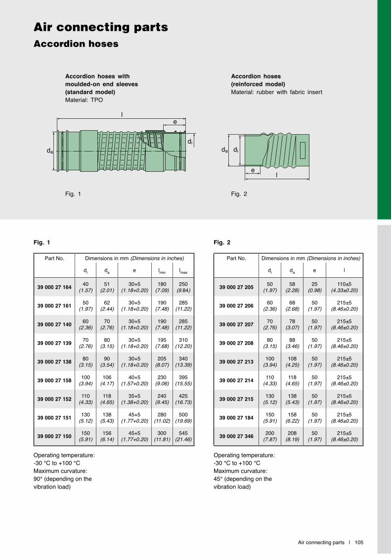
Air connecting parts | 105
Air connecting partsAccordion hoses
Part No. Dimensions in mm (Dimensions in inches)
di da e lmin lmax
39 000 27 164 40(1.57)
51(2.01)
30+5(1.18+0.20)
180(7.09)
250(9.84)
39 000 27 161 50(1.97)
62(2.44)
30+5(1.18+0.20)
190(7.48)
285(11.22)
39 000 27 140 60(2.36)
70(2.76)
30+5(1.18+0.20)
190(7.48)
285(11.22)
39 000 27 139 70(2.76)
80(3.15)
30+5(1.18+0.20)
195(7.68)
310(12.20)
39 000 27 138 80(3.15)
90(3.54)
30+5(1.18+0.20)
205(8.07)
340(13.39)
39 000 27 158 100(3.94)
106(4.17)
40+5(1.57+0.20)
230(9.06)
395(15.55)
39 000 27 152 110(4.33)
118(4.65)
35+5(1.38+0.20)
240(9.45)
425(16.73)
39 000 27 151 130(5.12)
138(5.43)
45+5(1.77+0.20)
280(11.02)
500(19.69)
39 000 27 150 150(5.91)
156(6.14)
45+5(1.77+0.20)
300(11.81)
545(21.46)
Part No. Dimensions in mm (Dimensions in inches)
di da e l
39 000 27 205 50(1.97)
58(2.28)
25(0.98)
110±5(4.33±0.20)
39 000 27 206 60(2.36)
68(2.68)
50(1.97)
215±5(8.46±0.20)
39 000 27 207 70(2.76)
78(3.07)
50(1.97)
215±5(8.46±0.20)
39 000 27 208 80(3.15)
88(3.46)
50(1.97)
215±5(8.46±0.20)
39 000 27 213 100(3.94)
108(4.25)
50(1.97)
215±5(8.46±0.20)
39 000 27 214 110(4.33)
118(4.65)
50(1.97)
215±5(8.46±0.20)
39 000 27 215 130(5.12)
138(5.43)
50(1.97)
215±5(8.46±0.20)
39 000 27 184 150(5.91)
158(6.22)
50(1.97)
215±5(8.46±0.20)
39 000 27 346 200(7.87)
208(8.19)
50(1.97)
215±5(8.46±0.20)
Operating temperature: -30 °C to +100 °CMaximum curvature: 45° (depending on the vibration load)
Operating temperature: -30 °C to +100 °C Maximum curvature: 90° (depending on the vibration load)
da
le
dida di
le
Accordion hoses with moulded-on end sleeves (standard model)Material: TPO
Accordion hoses (reinforced model)Material: rubber with fabric insert
Fig. 1
Fig. 1
Fig. 2
Fig. 2

106 | Air connecting parts
Air connecting partsStraight couplings in rubber
Part No. Dimensions in mm (Dimensions in inches)
di da l
39 000 27 203 40(1.57)
52(2.05)
100(3.94)
39 000 27 202 50(1.97)
63(2.48)
100(3.94)
39 000 27 198 60(2.36)
74(2.91)
150(5.91)
39 000 27 197 70(2.76)
84(3.31)
150(5.91)
39 000 27 252 70(2.76)
84(3.31)
80(3.15)
39 000 27 196 80(3.15)
96(3.78)
150(5.91)
39 000 27 950 80(3.15)
96(3.78)
75(2.95)
39 000 27 195 90(3.54)
106(4.17)
150(5.91)
39 000 27 104 100(3.94)
116(4.57)
100(3.94)
39 000 27 194 100(3.94)
118(4.65)
150(5.91)
Part No. Dimensions in mm (Dimensions in inches)
di da l
39 000 27 193 110(4.33)
126(4.96)
150(5.91)
39 000 27 359 110(4.33)
128(5.04)
75(2.95)
39 000 27 188 130(5.12)
148(5.83)
100(3.94)
39 000 27 192 130(5.12)
148(5.83)
150(5.91)
39 000 27 297 130(5.12)
148(5.83)
65(2.56)
39 000 27 183 150(5.91)
166(6.54)
150(5.91)
39 223 27 111 150(5.91)
168(6.61)
100(3.94)
39 000 27 182 180(7.09)
198(7.80)
150(5.91)
39 000 27 345 200(7.87)
218(8.58)
200(7.87)
39 000 27 306 210(8.27)
228(8.98)
200(7.87)
Straight couplingsMaterial: rubber (NBR. 60±5 Shore) with fabric insertOperating temperature: -30 °C to +100 °C
da di
l

Air connecting parts | 107
Air connecting partsElbow pipes in rubber / Couplings in metal
Part No. Fig. Dimensions in mm (Dimensions in inches)
b d1 da r
39 000 25 280 1 115(4.53)
52(2.05)
60(2.36)
75(2.95)
39 000 25 264 1 115(4.53)
60(2.36)
68(2.68)
75(2.95)
39 000 25 263 1 140(5.51)
70(2.76)
79(3.11)
90(3.54)
39 000 25 262 1 140(5.51)
80(3.15)
90(3.54)
95(3.74)
39 000 25 258 2 205(8.07)
100(3.94)
110(4.33)
155(6.10)
39 000 25 265 2 215(8.46)
110(4.33)
120(4.72)
165(6.50)
39 000 25 266 2 265(10.43)
130(5.12)
140(5.51)
210(8.27)
39 000 25 267 2 300(11.81)
150(5.91)
160(6.30)
245(9.65)
39 000 25 270 2 355(13.98)
200(7.87)
210(8.27)
300(11.81)
Part No. Fig. Dimensions in mm (Dimensions in inches)
da l s
39 000 25 177 3 52(2.05)
50(1.97)
0.75(0.03)
39 000 25 167 3 62(2.44)
65(2.56)
1.0(0.04)
39 000 25 164 3 70(2.76)
50(1.97)
1.0(0.04)
39 000 25 168 3 82(3.23)
50(1.97)
1.0(0.04)
39 000 25 165 3 92(3.62)
50(1.97)
1.0(0.04)
39 000 25 175 3 102(4.02)
50(1.97)
1.0(0.04)
39 000 25 176 3 110(4.33)
50(1.97)
1.0(0.04)
39 000 25 174 3 132(5.20)
50(1.97)
1.0(0.04)
39 000 25 184 3 150(5.91)
90(3.54)
1.0(0.04)
39 000 25 185 3 180(7.09)
90(3.54)
1.0(0.04)
90° elbowsMaterial: rubber (NBR. 60±5 Shore) with fabric insert
Operating temperature: -25 °C to +100 °C
Fig. 1 Fig. 2 Fig. 3
Couplings (black painted metal)
d1
r rb
da
b
d1
b
da
b
d1
r rb
da
b
d1
b
da
b
da
s
l

108 | Air connecting parts
Air connecting partsConnection pipes and couplings in metal
da di
l e
da
s
l
Fig. 4 Fig. 5
Part No. Fig. Dimensions in mm (Dimensions in inches)
di da e l
31 056 25 821 4 82.2(3.24)
82(3.23)
80(3.15)
245(9.65)
31 080 25 731 4 102.2(4.02)
102(4.02)
80(3.15)
250(9.84)
39 100 25 991 4 110.2(4.34)
110(4.33)
110(4.33)
200(7.87)
31 160 25 771 4 132.2(5.20)
132(5.20)
110(4.33)
400(15.75)
Part No. Fig. Dimensions in mm (Dimensions in inches)
da l s
39 000 25 172 5 42(1.65)
500(19.69)
0.75(0.03)
39 000 25 173 5 82(3.23)
500(19.69)
0.75(0.03)
39 000 25 158 5 92(3.62)
500(19.69)
0.75(0.03)
39 000 25 183 5 102(4.02)
500(19.69)
0.75(0.03)
39 000 25 166 5 110(4.33)
500(19.69)
0.75(0.03)
39 000 25 157 5 132(5.20)
500(19.69)
0.75(0.03)
39 000 25 155 5 150(5.91)
500(19.69)
0.75(0.03)
Intermediate pipe (black painted metal)only for dirty air intake
Pipes (black painted metal)
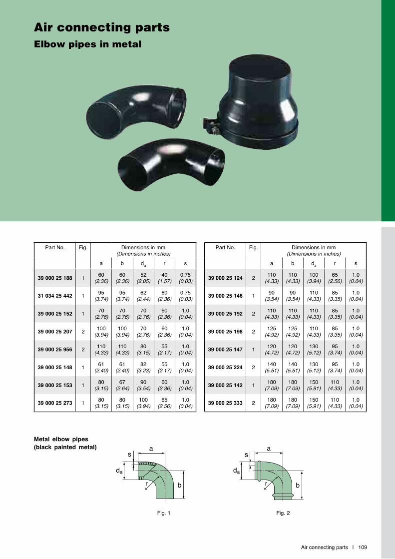
Air connecting parts | 109
Air connecting partsElbow pipes in metal
Part No. Fig. Dimensions in mm (Dimensions in inches)
a b da r s
39 000 25 188 1 60(2.36)
60(2.36)
52(2.05)
40(1.57)
0.75(0.03)
31 034 25 442 1 95(3.74)
95(3.74)
62(2.44)
60(2.36)
0.75(0.03)
39 000 25 152 1 70(2.76)
70(2.76)
70(2.76)
60(2.36)
1.0(0.04)
39 000 25 207 2 100(3.94)
100(3.94)
70(2.76)
60(2.36)
1.0(0.04)
39 000 25 956 2 110(4.33)
110(4.33)
80(3.15)
55(2.17)
1.0(0.04)
39 000 25 148 1 61(2.40)
61(2.40)
82(3.23)
55(2.17)
1.0(0.04)
39 000 25 153 1 80(3.15)
67(2.64)
90(3.54)
60(2.36)
1.0(0.04)
39 000 25 273 1 80(3.15)
80(3.15)
100(3.94)
65(2.56)
1.0(0.04)
Part No. Fig. Dimensions in mm (Dimensions in inches)
a b da r s
39 000 25 124 2 110(4.33)
110(4.33)
100(3.94)
65(2.56)
1.0(0.04)
39 000 25 146 1 90(3.54)
90(3.54)
110(4.33)
85(3.35)
1.0(0.04)
39 000 25 192 2 110(4.33)
110(4.33)
110(4.33)
85(3.35)
1.0(0.04)
39 000 25 198 2 125(4.92)
125(4.92)
110(4.33)
85(3.35)
1.0(0.04)
39 000 25 147 1 120(4.72)
120(4.72)
130(5.12)
95(3.74)
1.0(0.04)
39 000 25 224 2 140(5.51)
140(5.51)
130(5.12)
95(3.74)
1.0(0.04)
39 000 25 142 1 180(7.09)
180(7.09)
150(5.91)
110(4.33)
1.0(0.04)
39 000 25 333 2 180(7.09)
180(7.09)
150(5.91)
110(4.33)
1.0(0.04)
Metal elbow pipes (black painted metal)
da
r
s
b
a
da
r
s
b
a
Fig. 1 Fig. 2
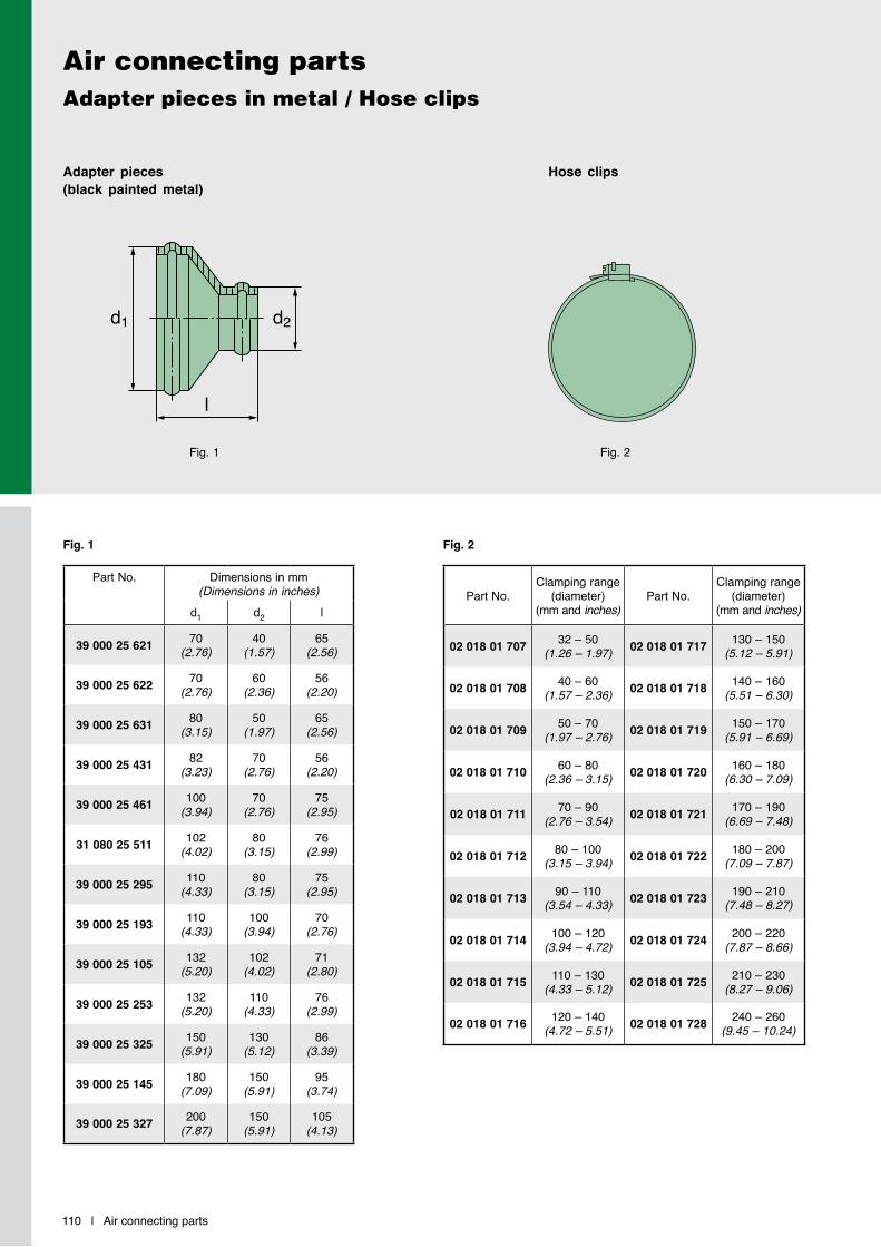
110 | Air connecting parts
Air connecting partsAdapter pieces in metal / Hose clips
Part No.Clamping range
(diameter) (mm and inches)
Part No.Clamping range
(diameter) (mm and inches)
02 018 01 707 32 – 50(1.26 – 1.97) 02 018 01 717 130 – 150
(5.12 – 5.91)
02 018 01 708 40 – 60(1.57 – 2.36) 02 018 01 718 140 – 160
(5.51 – 6.30)
02 018 01 709 50 – 70(1.97 – 2.76) 02 018 01 719 150 – 170
(5.91 – 6.69)
02 018 01 710 60 – 80(2.36 – 3.15) 02 018 01 720 160 – 180
(6.30 – 7.09)
02 018 01 711 70 – 90(2.76 – 3.54) 02 018 01 721 170 – 190
(6.69 – 7.48)
02 018 01 712 80 – 100(3.15 – 3.94) 02 018 01 722 180 – 200
(7.09 – 7.87)
02 018 01 713 90 – 110(3.54 – 4.33) 02 018 01 723 190 – 210
(7.48 – 8.27)
02 018 01 714 100 – 120(3.94 – 4.72) 02 018 01 724 200 – 220
(7.87 – 8.66)
02 018 01 715 110 – 130(4.33 – 5.12) 02 018 01 725 210 – 230
(8.27 – 9.06)
02 018 01 716 120 – 140(4.72 – 5.51) 02 018 01 728 240 – 260
(9.45 – 10.24)
Adapter pieces (black painted metal)
Hose clips
d1 d2
l
Part No. Dimensions in mm (Dimensions in inches)
d1 d2 l
39 000 25 621 70(2.76)
40(1.57)
65(2.56)
39 000 25 622 70(2.76)
60(2.36)
56(2.20)
39 000 25 631 80(3.15)
50(1.97)
65(2.56)
39 000 25 431 82(3.23)
70(2.76)
56(2.20)
39 000 25 461 100(3.94)
70(2.76)
75(2.95)
31 080 25 511 102(4.02)
80(3.15)
76(2.99)
39 000 25 295 110(4.33)
80(3.15)
75(2.95)
39 000 25 193 110(4.33)
100(3.94)
70(2.76)
39 000 25 105 132(5.20)
102(4.02)
71(2.80)
39 000 25 253 132(5.20)
110(4.33)
76(2.99)
39 000 25 325 150(5.91)
130(5.12)
86(3.39)
39 000 25 145 180(7.09)
150(5.91)
95(3.74)
39 000 25 327 200(7.87)
150(5.91)
105(4.13)
Fig. 1 Fig. 2
Fig. 2Fig. 1

Exhaust ejectors | 111
Installation instructions
The connection pipe between the air cleaner and ejector should be as short as possible and not have any tight elbows which would increase flow resistance. Coarse contaminant particles in the intake air (e.g. awns.
fibres. stems or leaves) can lead to clogging in the air cleaner. In order to avoid this, the scavenging should either be made in a closed area (cool-ing air shaft, scavenging under engine
bonnet) or in-stalled upstream with a basket sieve.When using an ejector, care should also be taken that the maximum permissible exhaust back pressure specified by the engine producer is not exceeded.
In addition, in all operational conditions there must be a pressure drop to the ejector in order to prevent exhaust gas being sucked in. In case of doubt we recommend use of a non-return adapter.
MANN+HUMMEL ejectors are designed to provide maintenance-free scavenging of the pre-separated dust in two-stage air cleaners. In addition to being mainte-nance-free, the ejectors achieve a significantly improved pre-separation efficiency of the two-stage air cleaner. This enables a considerably longer filter service life (up to 60%).
The ejector is fitted behind the exhaust silencer on the tailpipe. The flow energy of the exhaust gases generates a negative pressure in the ejector. This enables the pre-separated dust to be scavenged to the ejector and the dust is then blown out together with the exhaust gases.
Exhaust ejectorsMaintenance-free dust scavenging with two-stage air cleaners
Installation example
Exhaust silencer MANN+HUMMEL
Ejector
IQORON Air cleaner
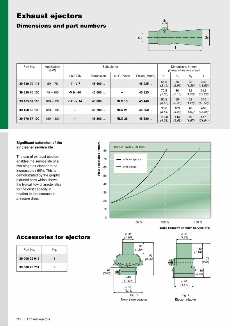
Significant extension of the air cleaner service life
The use of exhaust ejectors enables the service life of a two-stage air cleaner to be increased by 60%. This is demonstrated by the graphic pictured here which shows the typical flow characteristics for the dust capacity in relation to the increase in pressure drop.
112 | Exhaust ejectors
Exhaust ejectorsDimensions and part numbers
l
d3
d1 d2
Accessories for ejectors
Fig. 1 Non-return adapter
Fig. 2 Ejector adapter
Dust capacity (= filter service life)
Flow
res
ista
nce
[mba
r]
50 % 100 % 160 %
80
70
60
50
40
30
20
10
0
without ejector
with ejector
Service point = 80 mbar
Part No. Application [kW]
Suitable for Dimensions in mm (Dimensions in inches)
IQORON Europiclon NLG-Piclon Piclon (Metal) d1 d2 d3 l
39 330 70 111 50 – 75 -7, -V 7 45 400 ... – 45 225 ... 55.5(2.19)
75(2.95)
32(1.26)
352(13.86)
39 330 70 100 75 – 100 -V 9, -10 45 500 ... – 45 325 ... 72.5(2.85)
80(3.15)
32(1.26)
312(12.28)
39 105 67 110 100 – 130 -12, -V 14 45 600 ... NLG 15 45 440 ... 80.2(3.16)
88(3.46)
32(1.26)
345(13.58)
39 150 65 100 130 – 195 – 45 700 ... NLG 21 45 650 ... 90.0(3.54)
109(4.29)
40(1.57)
416(16.38)
39 170 67 100 180 – 300 – 45 800 ... NLG 28 45 880 ... 110.0(4.33)
143(5.63)
40(1.57)
547(21.54)
Part No. Fig.
39 000 25 919 1
39 000 25 751 221
(0.83)
ø 32(1.26)
ø 40(1.57) ø 40
(1.57)ø 80
(3.15)
ø 32(1.26)
33(1.30) 30
(1.18)
71(2.80)
30(0.79)
93(3.66)
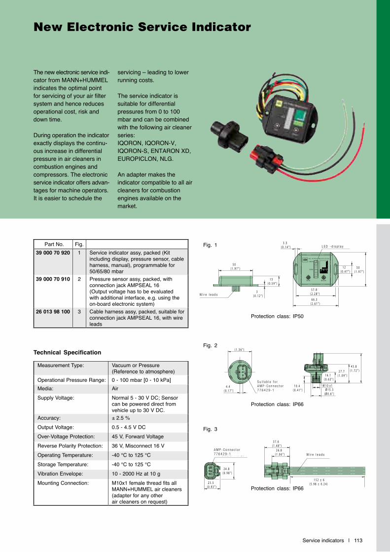
Service indicators | 113
The new electronic service indi-cator from MANN+HUMMEL indicates the optimal point for servicing of your air filter system and hence reduces operational cost, risk and down time.
During operation the indicator exactly displays the continu-ous increase in differential pressure in air cleaners in combustion engines and compressors. The electronic service indicator offers advan-tages for machine operators. It is easier to schedule the
servicing – leading to lower running costs.
The service indicator is suitable for differential pressures from 0 to 100 mbar and can be combined with the following air cleaner series: IQORON, IQORON-V, IQORON-S, ENTARON XD, EUROPICLON, NLG.
An adapter makes the indicator compatible to all air cleaners for combustion engines available on the market.
New Electronic Service Indicator
Technical Specification
Measurement Type: Vacuum or Pressure (Reference to atmosphere)
Operational Pressure Range: 0 - 100 mbar [0 - 10 kPa]Media: AirSupply Voltage: Normal 5 - 30 V DC; Sensor
can be powered direct from vehicle up to 30 V DC.
Accuracy: ± 2.5 %Output Voltage: 0.5 - 4.5 V DCOver-Voltage Protection: 45 V, Forward VoltageReverse Polarity Protection: 36 V, Misconnect 16 VOperating Temperature: -40 °C to 125 °CStorage Temperature: -40 °C to 125 °CVibration Envelope: 10 - 2000 Hz at 10 gMounting Connection: M10x1 female thread fits all
MANN+HUMMEL air cleaners (adapter for any other air cleaners on request)
Fig. 1
Fig. 2
Part No. Fig.39 000 70 920 1 Service indicator assy, packed (Kit
including display, pressure sensor, cable harness, manual), programmable for 50/65/80 mbar
39 000 70 910 2 Pressure sensor assy, packed, with connection jack AMPSEAL 16 (Output voltage has to be evaluated with additional interface, e.g. using the on-board electronic system)
26 013 98 100 3 Cable harness assy, packed, suitable for connection jack AMPSEAL 16, with wire leads
4 3 . 8( 1 . 7 2 " ) 2 7 . 7
( 1 . 0 9 " ) 1 6 . 1( 0 . 6 3 " )
Ø 1 5 . 3(Ø 0 . 6 " )
1 0 . 4( 0 . 4 1 " )
1 0M x 1
Ø 3 4 . 5( 1 . 3 6 " )
4 . 4( 0 . 1 7 " )
P a s s e n d f ü r A M P -S t e c k e r 7 7 6 4 2 9 - 1
D i m R e s e t
1 0 0 %
5 0 %
A i r F i l t e r R e s t r i c t i o n
L E D - B a l k e n a n z e i g e
5 7 . 8( 2 . 2 8 " )
6 6 . 3( 2 . 6 1 " )
3 . 5( 0 . 1 4 " )
5 0( 1 . 9 7 " )
1 2( 0 . 4 7 " )
V e r b i n d u n g s k a b e l
5 0( 1 . 9 7 " )
3( 0 . 1 2 " )
1 5( 0 . 5 9 " )
A M P - S t e c k e r 7 7 6 4 2 9 - 1
2 3 . 5( 0 . 9 3 " )
2 4 . 8( 0 . 9 8 " )
A n s c h l u s s k a b e l 2 6 . 8( 1 . 0 6 " )
3 7 . 6( 1 . 4 8 " )
W i r e l e a d s
L E D - d i s p l a y
Fig. 3
4 3 . 8( 1 . 7 2 " ) 2 7 . 7
( 1 . 0 9 " ) 1 6 . 1( 0 . 6 3 " )
Ø 1 5 . 3(Ø 0 . 6 " )
1 0 . 4( 0 . 4 1 " )
1 0M x 1
Ø 3 4 . 5( 1 . 3 6 " )
4 . 4( 0 . 1 7 " )
P a s s e n d f ü r A M P -S t e c k e r 7 7 6 4 2 9 - 1
D i m R e s e t
1 0 0 %
5 0 %
A i r F i l t e r R e s t r i c t i o n
L E D - B a l k e n a n z e i g e
5 7 . 8( 2 . 2 8 " )
6 6 . 3( 2 . 6 1 " )
3 . 5( 0 . 1 4 " )
5 0( 1 . 9 7 " )
1 2( 0 . 4 7 " )
V e r b i n d u n g s k a b e l
5 0( 1 . 9 7 " )
3( 0 . 1 2 " )
1 5( 0 . 5 9 " )
A M P - S t e c k e r 7 7 6 4 2 9 - 1
2 3 . 5( 0 . 9 3 " )
2 4 . 8( 0 . 9 8 " )
A n s c h l u s s k a b e l 2 6 . 8( 1 . 0 6 " )
1 5 2 ± 6( 5 . 9 8 ± 0 . 2 4 )
3 7 . 6( 1 . 4 8 " )
W i r e l e a d sA M P - C o n n e c t o r 7 7 6 4 2 9 - 1
Protection class: IP66
Protection class: IP50
4 3 . 8( 1 . 7 2 " ) 2 7 . 7
( 1 . 0 9 " ) 1 6 . 1( 0 . 6 3 " )
Ø 1 5 . 3(Ø 0 . 6 " )
1 0 . 4( 0 . 4 1 " )
1 0M x 1
Ø 3 4 . 5( 1 . 3 6 " )
4 . 4( 0 . 1 7 " )
P a s s e n d f ü r A M P -S t e c k e r 7 7 6 4 2 9 - 1
D i m R e s e t
1 0 0 %
5 0 %
A i r F i l t e r R e s t r i c t i o n
L E D - B a l k e n a n z e i g e
5 7 . 8( 2 . 2 8 " )
6 6 . 3( 2 . 6 1 " )
3 . 5( 0 . 1 4 " )
5 0( 1 . 9 7 " )
1 2( 0 . 4 7 " )
V e r b i n d u n g s k a b e l
5 0( 1 . 9 7 " )
3( 0 . 1 2 " )
1 5( 0 . 5 9 " )
A M P - S t e c k e r 7 7 6 4 2 9 - 1
2 3 . 5( 0 . 9 3 " )
2 4 . 8( 0 . 9 8 " )
A n s c h l u s s k a b e l 2 6 . 8( 1 . 0 6 " )
3 7 . 6( 1 . 4 8 " )
S u i t a b l e f o r A M P - C o n n e c t o r 7 7 6 4 2 9 - 1
Protection class: IP66
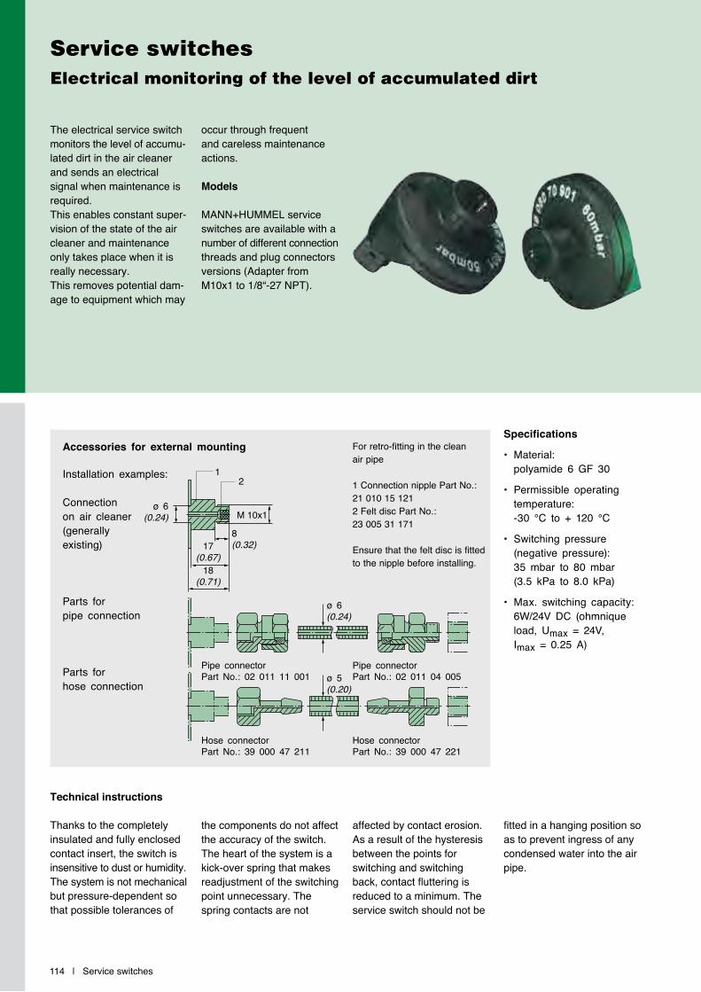
Installation examples:
Connection on air cleaner(generally existing)
Parts for pipe connection
Parts for hose connection
Specifications
• Material: polyamide 6 GF 30
• Permissible operating temperature: -30 °C to + 120 °C
• Switching pressure (negative pressure): 35 mbar to 80 mbar (3.5 kPa to 8.0 kPa)
• Max. switching capacity: 6W/24V DC (ohmnique load, Umax = 24V, Imax = 0.25 A)
Accessories for external mounting
Technical instructions
Thanks to the completely insulated and fully enclosed contact insert, the switch is insensitive to dust or humidity. The system is not mechanical but pressure-dependent so that possible tolerances of
the components do not affect the accuracy of the switch.The heart of the system is a kick-over spring that makes readjustment of the switching point unnecessary. The spring contacts are not
affected by contact erosion. As a result of the hysteresis between the points for switching and switching back, contact fluttering is reduced to a minimum. The service switch should not be
fitted in a hanging position so as to prevent ingress of any condensed water into the air pipe.
The electrical service switch monitors the level of accumu- lated dirt in the air cleaner and sends an electrical signal when maintenance is required. This enables constant super-vision of the state of the air cleaner and maintenance only takes place when it is really necessary. This removes potential dam-age to equipment which may
occur through frequent and careless maintenance actions.
Models
MANN+HUMMEL service switches are available with a number of different connection threads and plug connectors versions (Adapter from M10x1 to 1/8“-27 NPT).
114 | Service switches
Service switchesElectrical monitoring of the level of accumulated dirt
M 10x1
Pipe connector Part No.: 02 011 11 001
8(0.32)
12
ø 6(0.24)
ø 6(0.24)
ø 5(0.20)
17(0.67)
18(0.71)
Hose connectorPart No.: 39 000 47 211
Hose connectorPart No.: 39 000 47 221
Pipe connector Part No.: 02 011 04 005
For retro-fitting in the clean air pipe
1 Connection nipple Part No.: 21 010 15 1212 Felt disc Part No.: 23 005 31 171
Ensure that the felt disc is fitted to the nipple before installing.
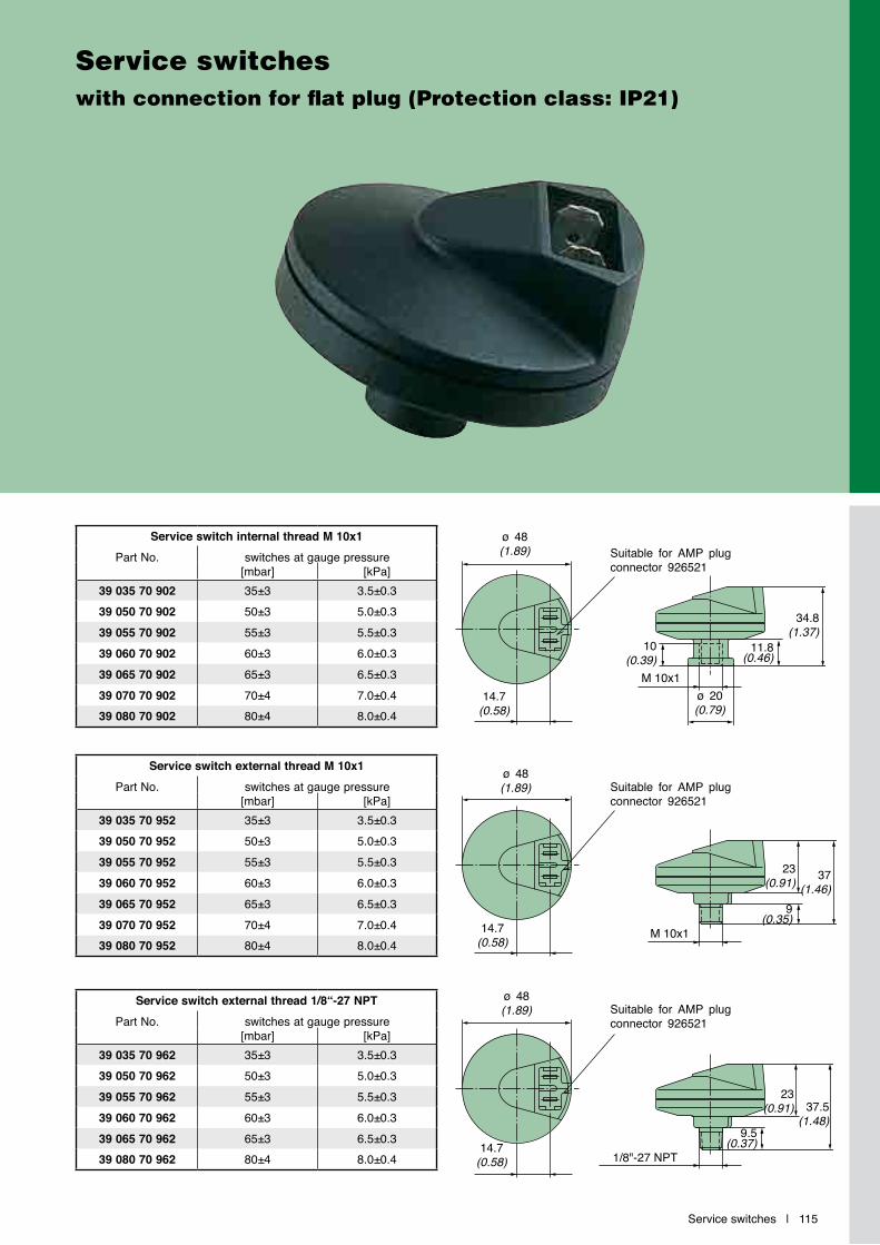
Service switches | 115
Service switcheswith connection for flat plug (Protection class: IP21)
Service switch internal thread M 10x1Part No. switches at gauge pressure
[mbar] [kPa]39 035 70 902 35±3 3.5±0.339 050 70 902 50±3 5.0±0.339 055 70 902 55±3 5.5±0.339 060 70 902 60±3 6.0±0.339 065 70 902 65±3 6.5±0.339 070 70 902 70±4 7.0±0.439 080 70 902 80±4 8.0±0.4
Service switch external thread M 10x1Part No. switches at gauge pressure
[mbar] [kPa]39 035 70 952 35±3 3.5±0.339 050 70 952 50±3 5.0±0.339 055 70 952 55±3 5.5±0.339 060 70 952 60±3 6.0±0.339 065 70 952 65±3 6.5±0.339 070 70 952 70±4 7.0±0.439 080 70 952 80±4 8.0±0.4
Service switch external thread 1/8“-27 NPTPart No. switches at gauge pressure
[mbar] [kPa]39 035 70 962 35±3 3.5±0.339 050 70 962 50±3 5.0±0.339 055 70 962 55±3 5.5±0.339 060 70 962 60±3 6.0±0.339 065 70 962 65±3 6.5±0.339 080 70 962 80±4 8.0±0.4
ø 48(1.89)
M 10x1
Suitable for AMP plug connector 926521
14.7(0.58)
ø 20(0.79)
10(0.39)
34.8(1.37)
ø 48(1.89)
M 10x1
Suitable for AMP plug connector 926521
37(1.46)
23(0.91)
14.7(0.58)
ø 48(1.89)
1/8"-27 NPT
Suitable for AMP plug connector 926521
23(0.91) 37.5
(1.48)
14.7(0.58)
11.8(0.46)
9(0.35)
9.5(0.37)
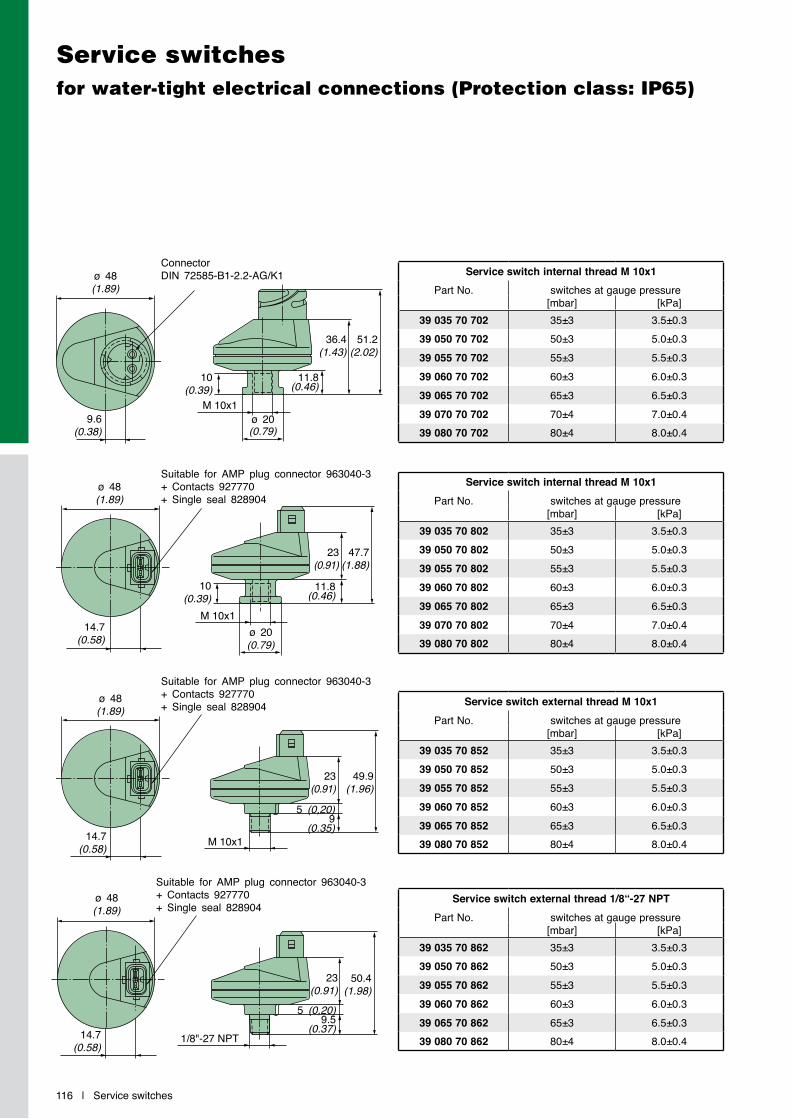
116 | Service switches
Service switchesfor water-tight electrical connections (Protection class: IP65)
Service switch internal thread M 10x1Part No. switches at gauge pressure
[mbar] [kPa]39 035 70 702 35±3 3.5±0.339 050 70 702 50±3 5.0±0.339 055 70 702 55±3 5.5±0.339 060 70 702 60±3 6.0±0.339 065 70 702 65±3 6.5±0.339 070 70 702 70±4 7.0±0.439 080 70 702 80±4 8.0±0.4
Service switch internal thread M 10x1Part No. switches at gauge pressure
[mbar] [kPa]39 035 70 802 35±3 3.5±0.339 050 70 802 50±3 5.0±0.339 055 70 802 55±3 5.5±0.339 060 70 802 60±3 6.0±0.339 065 70 802 65±3 6.5±0.339 070 70 802 70±4 7.0±0.439 080 70 802 80±4 8.0±0.4
Service switch external thread M 10x1Part No. switches at gauge pressure
[mbar] [kPa]39 035 70 852 35±3 3.5±0.339 050 70 852 50±3 5.0±0.339 055 70 852 55±3 5.5±0.339 060 70 852 60±3 6.0±0.339 065 70 852 65±3 6.5±0.339 080 70 852 80±4 8.0±0.4
Service switch external thread 1/8“-27 NPTPart No. switches at gauge pressure
[mbar] [kPa]39 035 70 862 35±3 3.5±0.339 050 70 862 50±3 5.0±0.339 055 70 862 55±3 5.5±0.339 060 70 862 60±3 6.0±0.339 065 70 862 65±3 6.5±0.339 080 70 862 80±4 8.0±0.4
ConnectorDIN 72585-B1-2.2-AG/K1
M 10x1
ø 48(1.89)
ø 20(0.79)
9.6(0.38)
10(0.39)
36.4(1.43)
51.2(2.02)
Suitable for AMP plug connector 963040-3+ Contacts 927770+ Single seal 828904
M 10x1ø 20(0.79)
ø 48(1.89)
10(0.39)
23(0.91)
47.7(1.88)
14.7(0.58)
Suitable for AMP plug connector 963040-3+ Contacts 927770+ Single seal 828904
M 10x1
ø 48(1.89)
23(0.91)
49.9(1.96)
14.7(0.58)
Suitable for AMP plug connector 963040-3+ Contacts 927770+ Single seal 828904
1/8"-27 NPT
ø 48(1.89)
23(0.91)
50.4(1.98)
14.7(0.58)
11.8(0.46)
11.8(0.46)
5 (0,20)9.5
(0.37)
5 (0,20)9
(0.35)

Service indicators | 117
Service indicatorsLevel of dirt accumulation readable at any tim
Part No. snaps into place at gauge pressure[mbar] [kPa]
39 035 70 911 35±3 3.5±0.339 050 70 911 50±4 5.0±0.439 050 70 931* 50±4 5.0±0.439 060 70 911 60±4 6.0±0.439 065 70 911 65±5 6.5±0.539 080 70 911 80±5 8.0±0.539 080 70 931* 80±5 8.0±0.5
Part No. snaps into place at gauge pressure[mbar] [kPa]
39 000 62 924 35±3 3.5±0.339 000 62 925 50±6 5.0±0.639 000 62 926 65±7 6.5±0.739 000 62 927 80±8 8.0±0.8
The MANN+HUMMEL service indicator allows you to read the current level of dirt accumulation in the air cleaner, even when the engine is not in operation. The yellow indicating piston catches on a scale of 12 snap-in positions. In the triangular display, the remaining service life of the filter is displayed, in relation to the increased clogging of the filter element.
The service indicator is in-sensitive to the intake air pulsations of the engine, ex- cluding the possibility of a false indication. Maintenance is necessary when the yellow piston reaches the red zone. After maintenance has been carried out, the indicator level is readjusted to “zero“ by pressing the reset button.
Specifications
• Material: PC
• Permissible operating temperature: -30 °C to +100 °C
• Switching pressure (negative pressure): 35 mbar to 80 mbar (3.5 kPa to 8 kPa)
* readable in vertical position
Specifications
• Material: PA
• Permissible operating temperature: -40 °C to +100 °C
• Switching pressure (negative pressure): 35 mbar to 80 mbar (3.5 kPa to 8 kPa)
The 90° connecting flange allows nearly any fitting position. The red indicating piston snaps into position upon reaching the maximum value possible, signalling that maintenance is needed. After maintenance has been carried out, the indicating piston is readjusted to the start position by pressing the reset button.
M 10x1
ø 46.7(1.84)
51.5(2.03)
1.2(0.05)
Service indicators with 90° flange
M 10x1
8.5(0.33)
62(2.44)
18(0.71)
10(0.39)
28(1.10)
35(1.38)
7(0.28)
Flange
Reset button
Sight glass for signal ring

118 |
Technical Appendix | 119
Technical Appendix
120 | Technical Appendix
Glossary of filtration terms
Clean air pipePipe after air cleaner through which cleaned air is fed to the engine/compressor etc.
Dirty air intakeDirty air pipe before the air cleaner through which ambient air (unfiltered) is sucked in.
DualSpinMANN+HUMMEL brand name for a precleaner line for use under heavy dust conditions.
Dust discharge valve Valve on the housing of two-stage air cleaners which discharges the separated dust from the air cleaner housing.
EjectorA component in the exhaust tract of the engine where a cross-section constriction (using the Venturi principle) generates a negative pres-sure for the continuous scav-enging of the air cleaner.
ENTARON XDMANN+HUMMEL brandname for an air cleaner line in plastic. This line is available as a single-stage or two-stage air cleaner.
EuropiclonMANN+HUMMEL brand name for a two-stage air cleaner line in plastic.
Flow resistance ∆p[mbar] or [kPa]. Measured variable for the pressure drop of a filter.
Glue String Technology GSTStandard technology for the new air cleaner series ENTARON XD. The glue string stabilizes the pleat ends so that the filter ele-ment can achieve its full per-formance under all operating conditions.
IQORON / IQORON-VMANN+HUMMEL brandname for an air cleaner line in plastic. This line is available as a single-stage or two-stage air cleaner.
IQORON-SMANN+HUMMEL brandname for an air cleaner line in plastic. This line is available as a single-stage air cleaner.
Laboratory dust capacity[g]. The measured quantity of a defined test dust which is added to a filter under laboratory conditions until the service point is reached.
Laboratory service life[h]. The time measured under laboratory conditions that an air cleaner with air flowing through it and loaded with dust will reach a defined flow resistance. The test dust, dust concentration and volume flow must be defined.
Main elementAlso called the filter element or primary element. An air cleaner insert consisting of a filter medium and seal which effect the fine filtration in a dry air cleaner.
NLGMANN+HUMMEL brand name for an air cleaner line in plastic. This line is avail-able as a single-stage or two-stage air cleaner.
Nominal flow rate V̇ Describes a design consi-deration for an air cleaner. Depending on the design or line the nominal flow rate describes the respective volume flow where the filter will show a pressure drop of 25 mbar to 30 mbar.
PiclonMANN+HUMMEL brand name for a two-stage air cleaner line in metal or in general for a two-stage version of a dry air cleaner (e.g. NLG Piclon).
Technical Appendix | 121
Glossary of filtration terms
PicoMANN+HUMMEL brand name for a single-stage air cleaner line in metal or in general for a single-stage version of a dry air cleaner (e.g. NLG Pico).
PicolightMANN+HUMMEL brand name for a single-stage air cleaner line without housing.
Picolino MANN+HUMMEL brand name for a single-stage air cleaner line in plastic.
PrecleanerCentrifugal force separator to filter out particles from the intake air.
Pre-separation efficiency [%]. Amount of dust separated in the first stage of a two-stage air cleaner.
PulsationPressure oscillations in the intake channel of an engine or a compressor.
Secondary elementAn additional air cleaner insert which is fitted down-stream from the main element and which prevents ingress of dust into the clean air pipe during maintenance work or when the main element is defective.
Service indicatorMounted device which indicates the time when to service.
Service life[h]. Life of filter determined in the field before the filter needs servicing.
Service switchMounted device which triggers an electric signal when the time for a service is reached which in turn sets off an audio or visual warning signal.
Single-stage air cleanerAir cleaner without pre - separation. Available with or without a secondary element.
Two-stage air cleanerAn air cleaner with an integrated filtration stage for pre-separation of dust from the intake air before subsequent fine filtration.
Volume flow V̇ [m3/min]. Quantity which flows through filter per unit of time, also called the volumetric flow.
122 | Technical Appendix
Design criteria
Service life
In order to determine the service life of a filter, a defined amount of dust is added to the filter in the test laboratory until an agreed differential pressure or a differential pressure defined according to ISO is achieved over the complete filter. During the test the differen-tial pressure increases constantly. The time from the start to the end of the test is
described as the laboratory service life of the air filter and is given in hours. The filter separation efficien- cy and the filter service life are characteristics of an air filter which can be verified at any time. In practice, the service life is usually longer due to the fact that the laboratory conditions are generally much more extreme than conditions in the field.
Example:
Filter 1: 99.93% separation efficiency
Filter 2: 99.97% separation efficiency
(1-0.9993) / (1-0.9997) = 2.3
The filter with a separation efficiency of 99.93% allows more dust through the filter by a factor of 2.3 than the filter with a separation efficiency of 99.97%.
Separation efficiency
The most important task of an air cleaner is to provide adequate protection for the application in use (e.g. engine, compressor, etc.) under all conceivable operating conditions. The separation efficiency of the filter there - fore has to be sufficiently high to meet this requirement. The measurement of the separation efficiency is defined by ISO 5011.
A dosing device is used to add dust to the filter with a defined particle size spectrum and concentration. The filter separates by far the largest part of this dust. The separation efficiency of the filter is given by the ratio of the separated dust mass to the dosed dust mass. The separation efficiency of dry air cleaners is usually above 99.95%.
For two-stage cleaners where a filter acts as a pre-separator an additional pre-separation efficiency is given which is determined in exactly the same way. A higher pre-separation efficiency correspondingly reduces the dust concentration which enters the main filter element and serves to lengthen the service life of the filter. The
total separation efficiency of the filter, on the other hand, is determined by the filter element. The often considerable differences in the passage of dust with different filters are only evident after a comparison of the different separation efficiencies has been made.
Technical Appendix | 123
Specification of filter size
Estimation of the design flow rate based on engine breake power
Fig. 1: Pulsation factors
1) Turbocharged engines do not require a pulsation factor.2) For compressors with gripper control a pulsation factor of 2 is valid.
If necessary data is not avail-able for the previous calcula-tion, the air requirement can be estimated using the fol-lowing approximations:
Diesel engines1 kW approx. 0.09 m3/min (1 HP approx. 0.065 m3/min)
Screw compressors1 kW approx. 0.15 m3/min
Petrol engines1 kW approx. 0.07 m3/min (1 HP approx. 0.05 m3/min)
Step 1: Determine the pulsation factors
With a small number of cylinders, flow pulsations occur in the intake system. The corresponding varying velocities must be taken into account when determining the size of the filter. The use of so-called pulsation factors (Fig. 1) can be used to overcome this problem.
Step 2: Determine the design flow rate
With 1-4 cylinders, the air requirement obtained above must be multiplied with the corresponding pulsation factor to determine the filter size. This results in the following equation (1):
Design flow rate = air requirement · pulsation factor
with air requirement in [m3/min]
For naturally aspirated engines with 5 or more cylinders, and for all turbo-charged engines, the air requirement corresponds to the design flow rate of the filter, i.e., the filter size is specified directly with the determined design flow rate (m3/min).
The nominal flow rate of the filter (m3/min) is a deciding factor for the air cleaner size.
Example 1:
3 cylinder 4 stroke Diesel engine with volume flow rate of 1.6 m³/min.
1. Pulsation factor from the table
Dry air cleaner 3 cylinder, 4 stroke engine Pulsation factor = 1.3
2. Design flow rate after equation (1)
V̇ = 1.6 m3/min · 1.3 V̇ = 2.1 m3/min Result: The design flow
rate of the engine is 2.1 m3/min.
Example 2:
Turbocharged Diesel engine with 107 kW power
V̇ = 107 · 0.09V̇ = 9.63 m³/min
Air intake
Naturally aspirated engines Piston compressors2)No. of cylinders 4 stroke engines 2 stroke engines Turbocharged1)
1 2 1.5 1 1.52 1.4 1.2 1 1.23 1.3 1.1 1 1.14 1.1 1 1 1
5 and more 1 1 1 1

124 | Technical Appendix
Defining the dust capacity
All MANN+HUMMEL air cleaners are tested on special test benches. The resulting data allows a uniform basis for comparison for the dust capacity of the various filter types and sizes. This offers true comparison possibilities for filters from different sources and enables a service life estimation for use in practice. On the following pages the mean value curves of the effective dust-holding capa-city for the described filters are illustrated based on the nominal volume flow (V̇ ).
Estimation of conditions in practice
Equation (2) is used in order to estimate the hours of operation in practice from the laboratory dust capacities.
Equation (2) indicates that the so-called service life of a filter directly depends on the laboratory dust capacity.
In addition to the influencing factors described in equation (2) such as laboratory dust capacity, dust concentration and air requirement,
These values relate to a standard ISO coarse test dust with an exactly defined particle size distribution and were determined with a dust concentration of 1 g/m3. Here one can speak of a so-called laboratory service life.In order to calculate the working service life in hours or driving kilometres from the laboratory dust-capacity data for a given dry air cleaner, the dust concentration prevailing in practice must be known. Extensive tests have led to the overview on this page (Fig. 2):
in practice there are further parameters which cannot be taken into account here. This includes, for example, the distribution of particle sizes and different air humidity levels. In practice, these influencing factors deviate from the standardised test conditions.
Fig. 2: Typical dust concentrations
Mean dust concentration in [mg/m3]
Truck in normal European road traffic 0.6
Truck in road traffic outside Europe 3
Off-highway truck (construction site use) 8
Construction machines (front-end loaders, track vehicles, mobile compressors) 35
Agricultural machines in central Europe (agriculture without periods of drought) 5
Agricultural machines in areas outside Europe in single operation 15
Agricultural machines used in fleets 50
Quick-moving track vehicles 100
Example 3:
A construction machine with an air requirement of 12 m3/min is equipped with a filter with a laboratory dust capacity of 5800 g. The expected hours of operation are to be calculated.
According to equation (2):
Hours of operation =
Hours of operation = 230 hours
5800 · 100035 · 12 · 60
Hours in practice =
with dust capacity in [g]dust concentration in [mg/m3]air requirement in [m3/min]
Equation (2): Estimated service life
laboratory dust capacity · 1000dust concentration · air requirement · 60
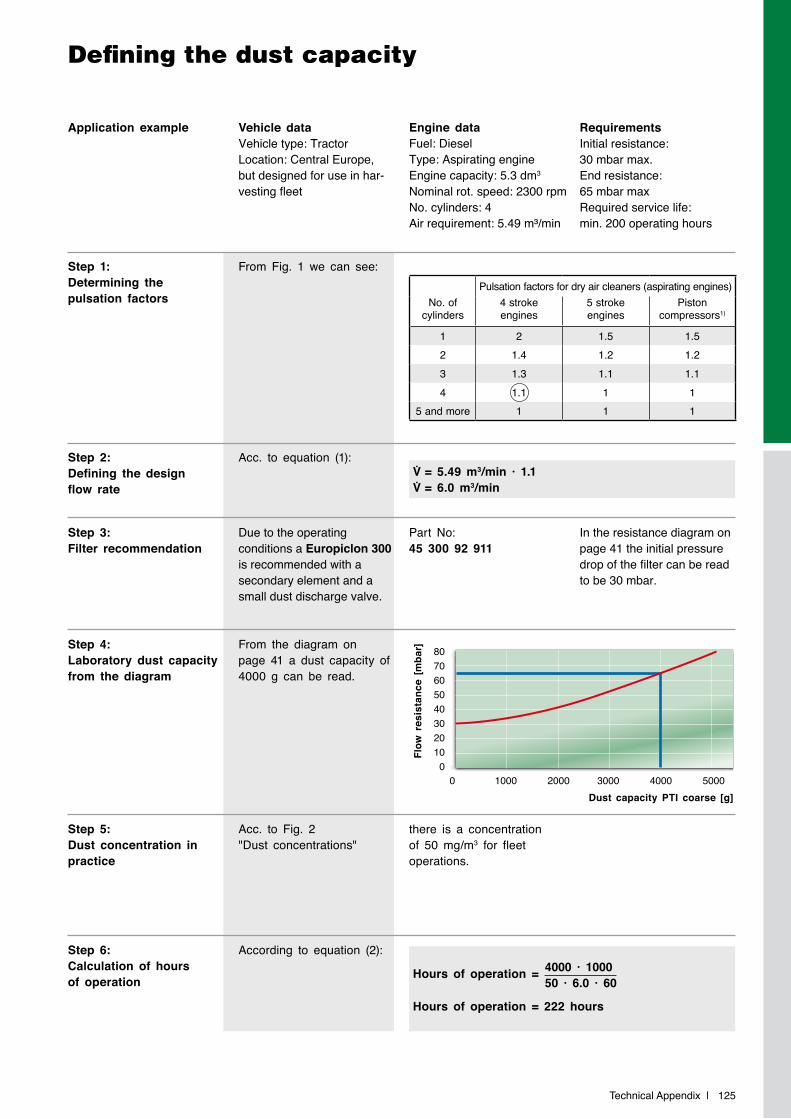
Technical Appendix | 125
Defining the dust capacity
Vehicle dataVehicle type: TractorLocation: Central Europe, but designed for use in har-vesting fleet
Step 1:Determining the pulsation factors
From Fig. 1 we can see:
Acc. to equation (1):
According to equation (2):
Step 3:Filter recommendation
Due to the operating conditions a Europiclon 300 is recommended with a secondary element and a small dust discharge valve.
Part No: 45 300 92 911
In the resistance diagram on page 41 the initial pressure drop of the filter can be read to be 30 mbar.
Step 4:Laboratory dust capacity from the diagram
Step 2:Defining the design flow rate
Step 5:Dust concentration in practice
From the diagram on page 41 a dust capacity of 4000 g can be read.
Acc. to Fig. 2 "Dust concentrations"
Application example Engine dataFuel: DieselType: Aspirating engineEngine capacity: 5.3 dm3
Nominal rot. speed: 2300 rpmNo. cylinders: 4Air requirement: 5.49 m³/min
RequirementsInitial resistance:30 mbar max.End resistance:65 mbar maxRequired service life:min. 200 operating hours
V̇ = 5.49 m3/min · 1.1V̇ = 6.0 m3/min
there is a concentration of 50 mg/m3 for fleet operations.
Pulsation factors for dry air cleaners (aspirating engines)No. of
cylinders4 stroke engines
5 stroke engines
Piston compressors1)
1 2 1.5 1.52 1.4 1.2 1.23 1.3 1.1 1.14 1.1 1 1
5 and more 1 1 1Fl
ow r
esis
tanc
e [m
bar]
Dust capacity PTI coarse [g]0 1000 2000 3000 4000 5000
8070605040302010
0
Step 6:Calculation of hours of operation Hours of operation =
Hours of operation = 222 hours
4000 · 100050 · 6.0 · 60
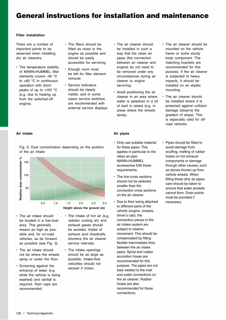
126 | Technical Appendix
General instructions for installation and maintenance
Filter installation
There are a number of important points to be observed when installing dry air cleaners:
• The temperature stability of MANN+HUMMEL filter elements covers -40 °C to +80 °C in continuous operation with short peaks of up to +100 °C (e.g. due to heating up from the switched-off engine).
• The filters should be fitted as close to the engine as possible and should be easily accessible for servicing.
• Enough room must be left for filter element removal.
• Service indicators should be clearly visible, and in some cases service switches are recommended with external service displays.
• The air cleaner should be installed in such a way that the clean air pipes (the connection between air cleaner and engine) do not need to be removed under any circumstances during air cleaner or engine servicing.
• Avoid positioning the air cleaner in an area where water is splashed or a lot of dust is raised (e.g. in areas where the wheels spray).
• The air cleaner should be mounted on the vehicle frame or some sturdy body component. The matching brackets are recommended for this purpose. If the air cleaner is subjected to heavy impacts, it should be installed on an elastic mounting.
• The air cleaner should be installed where it is protected against collision damage (observe the gradient of slope). This is especially valid for off-road vehicles.
Air intake
• The air intake should be located in a low-dust area. This generally means as high as pos-sible and, for on-road vehicles, as far forward as possible (see Fig. 3).
• The air intake should not be where the wheels spray or under the floor.
• Screening against the entrance of water (e.g. while the vehicle is being washed) and rainfall is required. Rain caps are recommended.
Air pipes
• Only use suitable material for these pipes. This applies in particular to the clean air pipe. MANN+HUMMEL accessories fulfil these requirements.
• The line cross sections should not be selected smaller than the connection cross sections on the air cleaner.
• Due to their being attached to different parts of the vehicle (engine, chassis, driver’s cab), the connection pieces in the air intake system are subject to relative movement. This should be compensated by fitting flexible intermediate links between the air intake pipes. Spiral and rubber accordion hoses are recommended for this purpose. The pipes are not tobe welded to the inlet and outlet connections on the air cleaner. Rubber hoses are also recommended for these connections.
• The intake of hot air (e.g. radiator cooling air) and exhaust gases should be avoided. Intake of exhaust soot drastically shortens the air cleaner service intervals.
• The intake openings should be as large as possible. Intake-flow velocities should not exceed 3 m/sec.
• Pipes should be fitted to avoid damage from scuffing, melting of rubber hoses on hot exhaust components or damage through other causes, such as stones thrown up from vehicle wheels. When fitting these dirty air pipes, care should be taken to ensure that water pockets cannot form. Drain points must be provided if necessary.
Fig. 3: Dust concentration depending on the position of the air intake
Rel
ativ
e du
st c
once
ntra
tion
%
Height above the ground (m)0.5 1.0 1.5 2.0 2.5 3.0
150
100
50
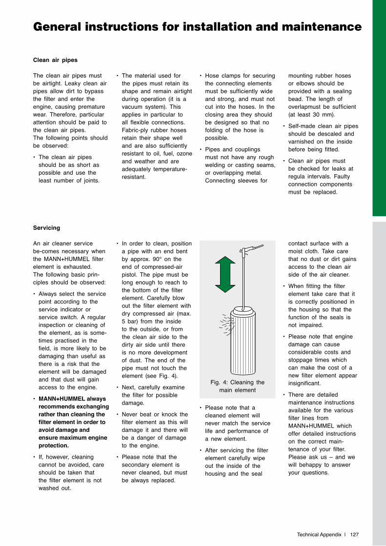
Technical Appendix | 127
General instructions for installation and maintenance
Clean air pipes
The clean air pipes must be airtight. Leaky clean air pipes allow dirt to bypass the filter and enter the engine, causing premature wear. Therefore, particular attention should be paid to the clean air pipes. The following points should be observed:
• The clean air pipes should be as short as possible and use the least number of joints.
Servicing
An air cleaner service be-comes necessary when the MANN+HUMMEL filter element is exhausted. The following basic prin-ciples should be observed:
• Always select the service point according to the service indicator or service switch. A regular inspection or cleaning of the element, as is some-times practised in the field, is more likely to be damaging than useful as there is a risk that the element will be damaged and that dust will gain access to the engine.
• MANN+HUMMEL always recommends exchanging rather than cleaning the filter element in order to avoid damage and ensure maximum engine protection.
• If, however, cleaning cannot be avoided, care should be taken that the filter element is not washed out.
• Please note that a cleaned element will never match the service life and performance of a new element.
• After servicing the filter element carefully wipe out the inside of the housing and the seal
• The material used for the pipes must retain its shape and remain airtight during operation (it is a vacuum system). This applies in particular to all flexible connections. Fabric-ply rubber hoses retain their shape well and are also sufficiently resistant to oil, fuel, ozone and weather and are adequately temperature-resistant.
• In order to clean, position a pipe with an end bent by approx. 90° on the end of compressed-air pistol. The pipe must be long enough to reach to the bottom of the filter element. Carefully blow out the filter element with dry compressed air (max. 5 bar) from the inside to the outside, or from the clean air side to the dirty air side until there is no more development of dust. The end of the pipe must not touch the element (see Fig. 4).
• Next, carefully examine the filter for possible damage.
• Never beat or knock the filter element as this will damage it and there will be a danger of damage to the engine.
• Please note that the secondary element is never cleaned, but must be always replaced.
contact surface with a moist cloth. Take care that no dust or dirt gains access to the clean air side of the air cleaner.
• When fitting the filter element take care that it is correctly positioned in the housing so that the function of the seals is not impaired.
• Please note that engine damage can cause considerable costs and stoppage times which can make the cost of a new filter element appear insignificant.
• There are detailed maintenance instructions available for the various filter lines from MANN+HUMMEL which offer detailed instructions on the correct main-tenance of your filter. Please ask us – and we will behappy to answer your questions.
• Hose clamps for securing the connecting elements must be sufficiently wide and strong, and must not cut into the hoses. In the closing area they should be designed so that no folding of the hose is possible.
• Pipes and couplings must not have any rough welding or casting seams, or overlapping metal. Connecting sleeves for
mounting rubber hoses or elbows should be provided with a sealing bead. The length of overlapmust be sufficient (at least 30 mm).
• Self-made clean air pipes should be descaled and varnished on the inside before being fitted.
• Clean air pipes must be checked for leaks at regula intervals. Faulty connection components must be replaced.
Fig. 4: Cleaning the main element
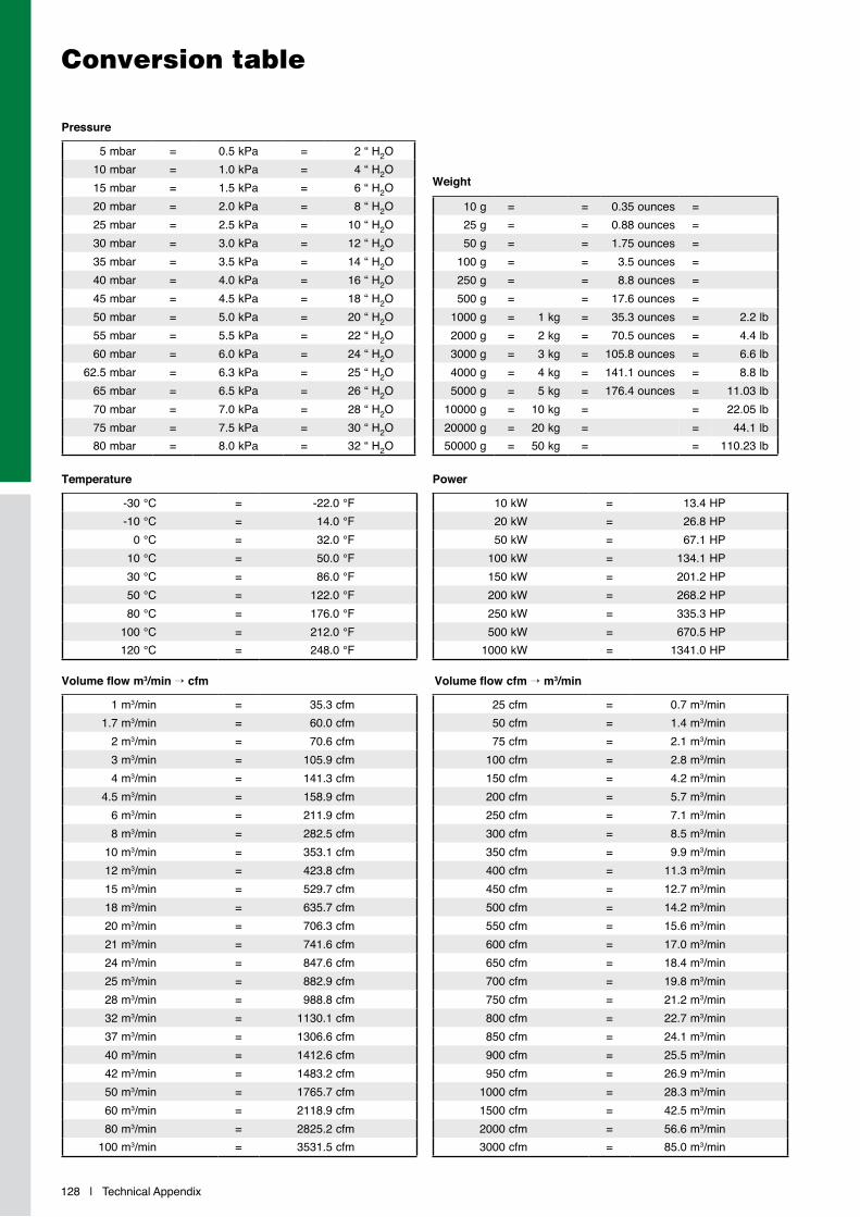
128 | Technical Appendix
Conversion table
-30 °C = -22.0 °F-10 °C = 14.0 °F
0 °C = 32.0 °F10 °C = 50.0 °F30 °C = 86.0 °F50 °C = 122.0 °F80 °C = 176.0 °F
100 °C = 212.0 °F120 °C = 248.0 °F
10 kW = 13.4 HP20 kW = 26.8 HP50 kW = 67.1 HP
100 kW = 134.1 HP150 kW = 201.2 HP200 kW = 268.2 HP250 kW = 335.3 HP500 kW = 670.5 HP
1000 kW = 1341.0 HP
Temperature Power
1 m3/min = 35.3 cfm1.7 m3/min = 60.0 cfm
2 m3/min = 70.6 cfm3 m3/min = 105.9 cfm4 m3/min = 141.3 cfm
4.5 m3/min = 158.9 cfm6 m3/min = 211.9 cfm8 m3/min = 282.5 cfm
10 m3/min = 353.1 cfm12 m3/min = 423.8 cfm15 m3/min = 529.7 cfm18 m3/min = 635.7 cfm20 m3/min = 706.3 cfm21 m3/min = 741.6 cfm24 m3/min = 847.6 cfm25 m3/min = 882.9 cfm28 m3/min = 988.8 cfm32 m3/min = 1130.1 cfm37 m3/min = 1306.6 cfm40 m3/min = 1412.6 cfm42 m3/min = 1483.2 cfm50 m3/min = 1765.7 cfm60 m3/min = 2118.9 cfm80 m3/min = 2825.2 cfm
100 m3/min = 3531.5 cfm
25 cfm = 0.7 m3/min50 cfm = 1.4 m3/min75 cfm = 2.1 m3/min
100 cfm = 2.8 m3/min150 cfm = 4.2 m3/min200 cfm = 5.7 m3/min250 cfm = 7.1 m3/min300 cfm = 8.5 m3/min350 cfm = 9.9 m3/min400 cfm = 11.3 m3/min450 cfm = 12.7 m3/min500 cfm = 14.2 m3/min550 cfm = 15.6 m3/min600 cfm = 17.0 m3/min650 cfm = 18.4 m3/min700 cfm = 19.8 m3/min750 cfm = 21.2 m3/min800 cfm = 22.7 m3/min850 cfm = 24.1 m3/min900 cfm = 25.5 m3/min950 cfm = 26.9 m3/min
1000 cfm = 28.3 m3/min1500 cfm = 42.5 m3/min2000 cfm = 56.6 m3/min3000 cfm = 85.0 m3/min
Volume flow m3/min → cfm Volume flow cfm → m3/min
5 mbar = 0.5 kPa = 2 “ H2O10 mbar = 1.0 kPa = 4 “ H2O15 mbar = 1.5 kPa = 6 “ H2O20 mbar = 2.0 kPa = 8 “ H2O25 mbar = 2.5 kPa = 10 “ H2O30 mbar = 3.0 kPa = 12 “ H2O35 mbar = 3.5 kPa = 14 “ H2O40 mbar = 4.0 kPa = 16 “ H2O45 mbar = 4.5 kPa = 18 “ H2O50 mbar = 5.0 kPa = 20 “ H2O55 mbar = 5.5 kPa = 22 “ H2O60 mbar = 6.0 kPa = 24 “ H2O
62.5 mbar = 6.3 kPa = 25 “ H2O65 mbar = 6.5 kPa = 26 “ H2O70 mbar = 7.0 kPa = 28 “ H2O75 mbar = 7.5 kPa = 30 “ H2O80 mbar = 8.0 kPa = 32 “ H2O
10 g = = 0.35 ounces =25 g = = 0.88 ounces =50 g = = 1.75 ounces =
100 g = = 3.5 ounces =250 g = = 8.8 ounces =500 g = = 17.6 ounces =
1000 g = 1 kg = 35.3 ounces = 2.2 lb2000 g = 2 kg = 70.5 ounces = 4.4 lb3000 g = 3 kg = 105.8 ounces = 6.6 lb4000 g = 4 kg = 141.1 ounces = 8.8 lb5000 g = 5 kg = 176.4 ounces = 11.03 lb
10000 g = 10 kg = = 22.05 lb20000 g = 20 kg = = 44.1 lb50000 g = 50 kg = = 110.23 lb
Pressure
Weight
Technical Appendix | 129
A selection of catalogues for MANN+HUMMEL Industrial Filters
ProVent
The product line for crankcase ventilation
Catalogue part no.19 944 10 100 (german)19 944 10 101 (english)Further languages on request.
PreLine
Pre-filter for diesel fuel Catalogue part no.W9 942 21 100 (german)W9 942 21 101 (english)Further languages on request.
Air/oil separators for compressors and vacuum pumps
Air/oil separator elementsAir/oil separator boxes
Catalogue part no.19 943 00 100 (german)19 943 00 101 (english)Further languages on request.
Filters for liquids
Spin-on filtersFuel filtersIn-line filters
Catalogue part no.19 942 10 100 (german)19 942 10 101 (english)Further languages on request.
MANN-FILTER
Filter elements in OEM quality for construction and agricultural machines:- Air cleaners- Oil filters- Fuel filters- Hydraulic filters- Cabin filters
Catalogue part no.19 939 24 600 (multi-lingual)

130 | Notes
Notes

Notes | 131
Notes

MANN+HUMMEL company
Joint venture company
The MANN+HUMMEL Group is an international company and employs over 14,750 people at 50 locations worldwide. The group develops, produces and distributes innovative technical components and systems for the automotive industry and many other industrial fields.
For more than 70 years the company has been a
specialist for high quality filtration products for vehicles, engines and industrial applications and is a reliable partner in the OEM business to leading producers of vehicles, machines and installations. Filters for the international aftermarket are sold under numerous international brands as well as under the company‘s own MANN-FILTER brand.
MANN+HUMMEL Industrial Filtration
The Industrial Filtration Business Unit with its headquarters in Speyer, Germany, specialises in meeting the requirements of off-highway vehicle and engine applications, compressed air and vacuum technology, mechanical engineering and plant construction. For these
and other industrial fields MANN+HUMMEL Industrial Filtration offers high performance products for the filtration and separation of air, gases and liquids.
MANN+HUMMEL GMBH, Business Unit Industrial Filtration67346 Speyer, Germany, Telephone +49 (62 32) 53-80, Fax +49 (62 32) 53-88 99
E-Mail: [email protected], Internet: www.mann-hummel.com
MANN+HUMMEL Group
19 9
41 1
0 10
1 en
081
3 Pr
inte
d in
Ger
man
y ©
MAN
N+H
UM
MEL
GM
BH