manifa oil field: large scale experiences with breakwaters ... · manifa oil field: large scale...
TRANSCRIPT
24 Terra et Aqua | Number 135 | June 2014
MANIFA OIL FIELD: LARGE SCALE EXPERIENCES WITH BREAKWATERS – AN INNOVATIVE APPROACH
PETER DE POOTER, MAGGY DE MAN, EDWARD VAN MELKEBEEKAND AND WIM VAN ALBOOM
ABSTRACT
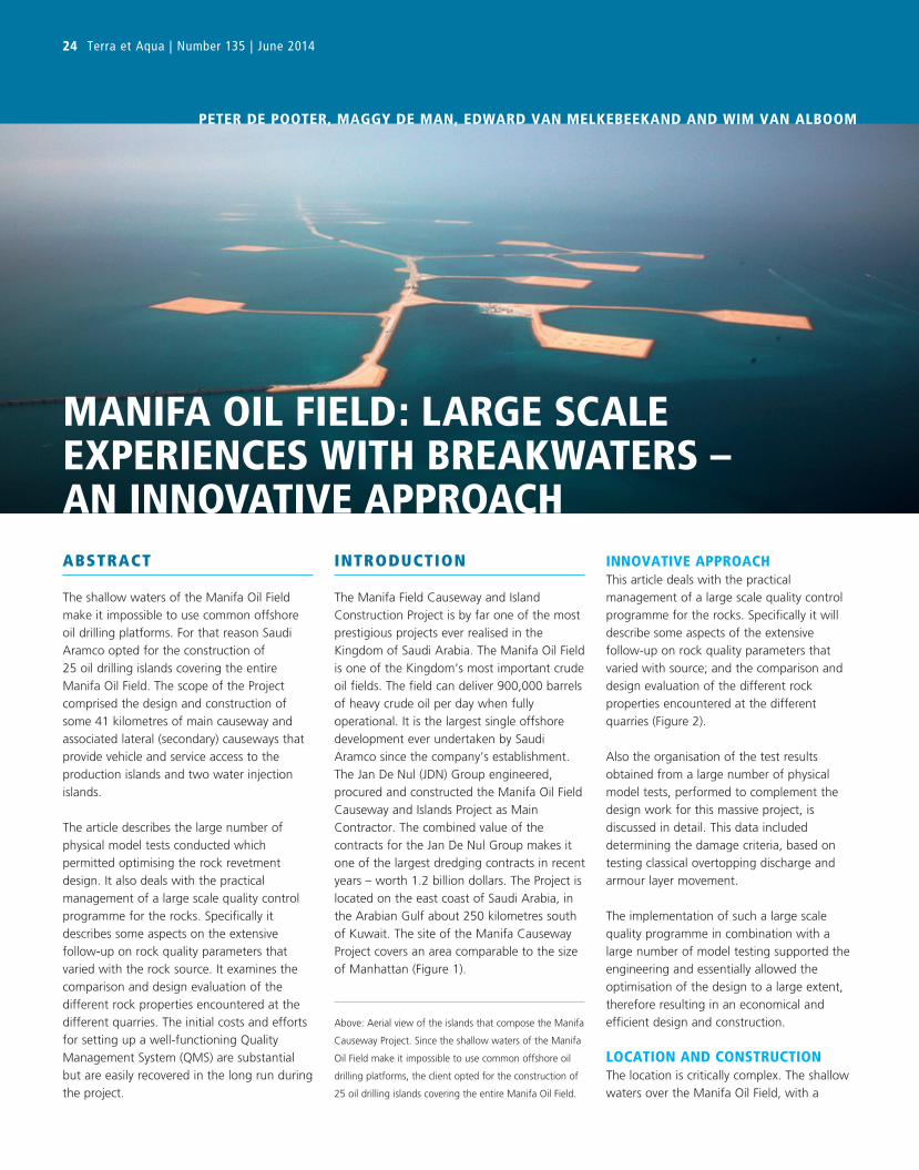
The shallow waters of the Manifa Oil Field
make it impossible to use common offshore
oil drilling platforms. For that reason Saudi
Aramco opted for the construction of
25 oil drilling islands covering the entire
Manifa Oil Field. The scope of the Project
comprised the design and construction of
some 41 kilometres of main causeway and
associated lateral (secondary) causeways that
provide vehicle and service access to the
production islands and two water injection
islands.
The article describes the large number of
physical model tests conducted which
permitted optimising the rock revetment
design. It also deals with the practical
management of a large scale quality control
programme for the rocks. Specifically it
describes some aspects on the extensive
follow-up on rock quality parameters that
varied with the rock source. It examines the
comparison and design evaluation of the
different rock properties encountered at the
different quarries. The initial costs and efforts
for setting up a well-functioning Quality
Management System (QMS) are substantial
but are easily recovered in the long run during
the project.
INTRODUCTION
The Manifa Field Causeway and Island
Construction Project is by far one of the most
prestigious projects ever realised in the
Kingdom of Saudi Arabia. The Manifa Oil Field
is one of the Kingdom’s most important crude
oil fields. The field can deliver 900,000 barrels
of heavy crude oil per day when fully
operational. It is the largest single offshore
development ever undertaken by Saudi
Aramco since the company’s establishment.
The Jan De Nul (JDN) Group engineered,
procured and constructed the Manifa Oil Field
Causeway and Islands Project as Main
Contractor. The combined value of the
contracts for the Jan De Nul Group makes it
one of the largest dredging contracts in recent
years – worth 1.2 billion dollars. The Project is
located on the east coast of Saudi Arabia, in
the Arabian Gulf about 250 kilometres south
of Kuwait. The site of the Manifa Causeway
Project covers an area comparable to the size
of Manhattan (Figure 1).
INNOVATIVE APPROACHThis article deals with the practical
management of a large scale quality control
programme for the rocks. Specifically it will
describe some aspects of the extensive
follow-up on rock quality parameters that
varied with source; and the comparison and
design evaluation of the different rock
properties encountered at the different
quarries (Figure 2).
Also the organisation of the test results
obtained from a large number of physical
model tests, performed to complement the
design work for this massive project, is
discussed in detail. This data included
determining the damage criteria, based on
testing classical overtopping discharge and
armour layer movement.
The implementation of such a large scale
quality programme in combination with a
large number of model testing supported the
engineering and essentially allowed the
optimisation of the design to a large extent,
therefore resulting in an economical and
efficient design and construction.
LOCATION AND CONSTRUCTIONThe location is critically complex. The shallow
waters over the Manifa Oil Field, with a
Above: Aerial view of the islands that compose the Manifa
Causeway Project. Since the shallow waters of the Manifa
Oil Field make it impossible to use common offshore oil
drilling platforms, the client opted for the construction of
25 oil drilling islands covering the entire Manifa Oil Field.
Over a period of 3 years, 27 islands each
with 10 well locations, as well as causeways
with a total length of 41 kilometres, including
14 bridges – of which the longest is
2.4 kilometres – and 3 berthing areas with
2 roll-on /roll-off facilities for supply vessels,
were designed and built (Figures 4 and 5).
This included road surfacing and pipeline and
cable trays for the export lines and the
SCADA system. Several shore approaches for
pipelines and cables had to be dredged and
abandoned pipelines had to be removed.
The causeways and islands essentially consist
maximum of 6 metres depth, make it
impossible to use common offshore oil drilling
platforms. For that reason Saudi Aramco
opted for the construction of 25 oil drilling
islands covering the entire Manifa Oil Field.
The overall scope of the Project of the
Jan De Nul (JDN) Group comprised the design
and construction of the 25 oil drilling and
production islands, 2 water injection islands
(Figure 3) and some 41 kilometres of main
and associated lateral causeways that provide
vehicle and service access from shore to the
islands.
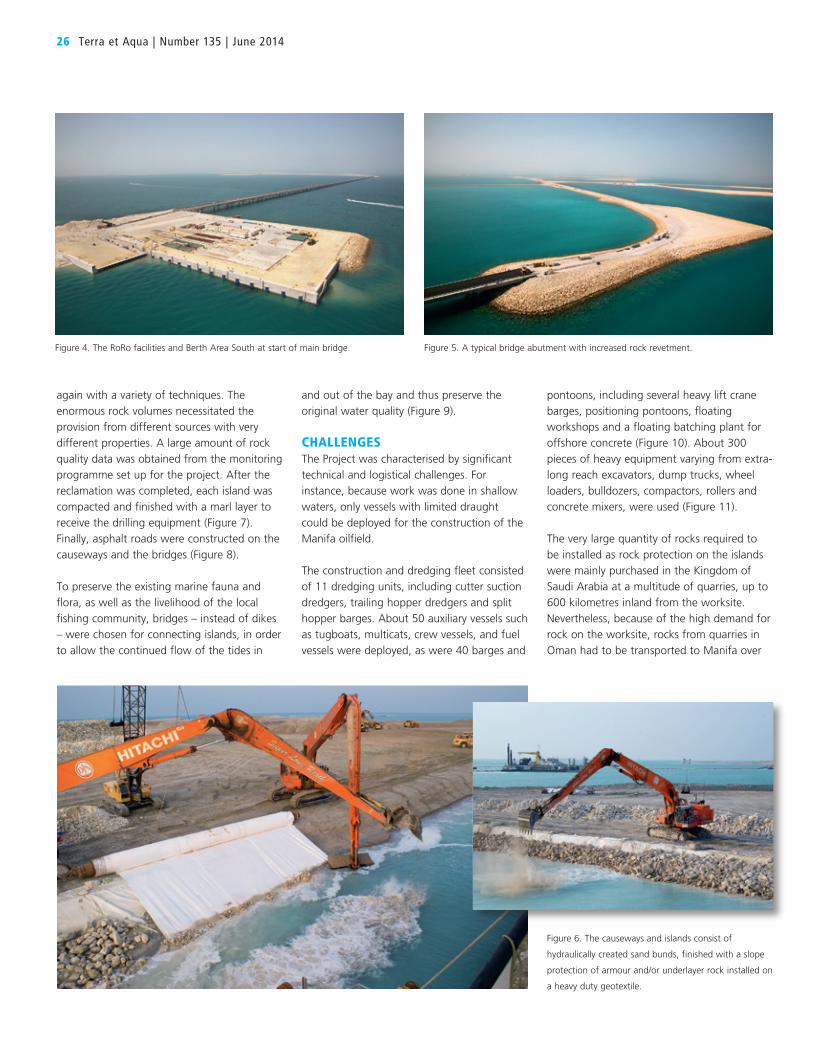
of hydraulically created sand cores, finished
with a slope protection of armour and/or
underlayer rock installed on a heavy duty
geotextile (Figure 6). Several innovative
installation techniques for the geotextile have
been used. Rock has then been installed from
the land side as well as from the waterside,
Manifa Oil Field : Large Scale Experiences with Breakwaters – An Innovative Approach 25
THE CONTRACT
• 25 oil drilling islands and 2 water injection
islands
• 41 km of causeways and roads
• 121 km rock revetment
• 14 bridges with a cumulative span of more
than 4 km (1 main of 2.4 km, 5 short of
180 m and 8 of 90 m)
• 3 marine access areas including quay walls,
lay-down areas and RoRo facilities
• 52,000,000 m³ of dredged material
• 12,000,000 tonnes of rock for revetment
• 6 quarries, up to 600 km from site
• 150,000 m³ of concrete casted on site
• 9 km subsea dredging
• 6,000 m of abandoned subsea pipeline
removal
• 2 pipeline shore approaches
• 11 dredgers and 100 units floating equipment
• 300 units heavy construction equipment
• 3,000 workforces, 24 hrs. operation,
40 nationalities
• Camp infrastructure for 2,000 residents
• 22,000,000 work-hours for construction scope
• 100,000 work-hours for engineering scope
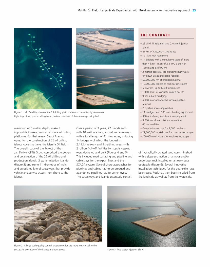
Figure 1. Left: Satellite photo of the 25 drilling platform islands connected by causeways.
Right top: close up of a drilling island; below: overview of the causeways being built.
Figure 2. A large scale quality control programme for the rocks was crucial to the
successful execution of the islands and causeways. Figure 3. Two water injection islands.
again with a variety of techniques. The
enormous rock volumes necessitated the
provision from different sources with very
different properties. A large amount of rock
quality data was obtained from the monitoring
programme set up for the project. After the
reclamation was completed, each island was
compacted and finished with a marl layer to
receive the drilling equipment (Figure 7).
Finally, asphalt roads were constructed on the
causeways and the bridges (Figure 8).
To preserve the existing marine fauna and
flora, as well as the livelihood of the local
fishing community, bridges – instead of dikes
– were chosen for connecting islands, in order
to allow the continued flow of the tides in
26 Terra et Aqua | Number 135 | June 2014
and out of the bay and thus preserve the
original water quality (Figure 9).
CHALLENGESThe Project was characterised by significant
technical and logistical challenges. For
instance, because work was done in shallow
waters, only vessels with limited draught
could be deployed for the construction of the
Manifa oilfield.
The construction and dredging fleet consisted
of 11 dredging units, including cutter suction
dredgers, trailing hopper dredgers and split
hopper barges. About 50 auxiliary vessels such
as tugboats, multicats, crew vessels, and fuel
vessels were deployed, as were 40 barges and
pontoons, including several heavy lift crane
barges, positioning pontoons, floating
workshops and a floating batching plant for
offshore concrete (Figure 10). About 300
pieces of heavy equipment varying from extra-
long reach excavators, dump trucks, wheel
loaders, bulldozers, compactors, rollers and
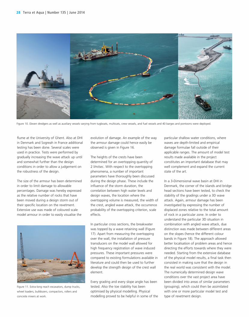
concrete mixers, were used (Figure 11).
The very large quantity of rocks required to
be installed as rock protection on the islands
were mainly purchased in the Kingdom of
Saudi Arabia at a multitude of quarries, up to
600 kilometres inland from the worksite.
Nevertheless, because of the high demand for
rock on the worksite, rocks from quarries in
Oman had to be transported to Manifa over
Figure 5. A typical bridge abutment with increased rock revetment.
Figure 6. The causeways and islands consist of
hydraulically created sand bunds, finished with a slope
protection of armour and/or underlayer rock installed on
a heavy duty geotextile.
Figure 4. The RoRo facilities and Berth Area South at start of main bridge.
sea. The number of different gradings had to
be limited for logistical reasons (Figure 12).
Before transporting a batch of rocks, each
batch was tested on a daily basis for density
and resistance in laboratories at the quarries
and at the project site. Actual field drop tests
(Figure 13) were performed as well as shape
and grading verification. The massive stream
of test results required setting up a practical
and performance QMS structure able to
respond quickly, and to follow the
construction progress.
The main logistical challenge was to deliver
and supply the equipment and the materials
such as rocks, aggregates, containers,
equipment, fuel, food, and so on, to such
a remote working place where JDN was the
first contractor to arrive. At peak periods a
workforce of more than 3,000 workers from
more than 40 different nationalities, were at
work simultaneously. Sourcing this workforce
at short notice and accommodating them
in the empty desert required ingenuity.
A camp in line with Saudi Aramco’s very
high standards was constructed in the
remote desert (Figure 14).
PHYSICAL MODEL TESTINGThe rocks were treated as precious stones,
and the consumption of these precious stones
had to be kept to an absolute minimum. The
design life of the project is 50 years. Several
case studies were performed for many
different locations in the work and for a storm
with a return period of 100 years. The
required different gradings for the rock
revetment on different locations was obtained
through detailed numerical wave modelling
and then tested by physical modelling in wave
flumes and wave basins (2D/3D) (Figure 15).
To optimise the design of the rock revetments,
a large number of physical modelling tests
have been done in a 2 dimensional wave
Manifa Oil Field : Large Scale Experiences with Breakwaters – An Innovative Approach 27
PETER DE POOTER
graduated in 1990 with a MSc in Civil
Engineering from the University of Ghent
(Belgium). He joined the Jan De Nul Group
in 2003. Since then he has been employed
as Engineering Manager on the offshore
project Sakhalin II (Russia) and as Project
Manager and Project Director on many
other offshore projects worldwide.
Presently he is working as Project Manager
on the Wheatstone Solid Ballasting Project
in West Australia.
MAGGY DE MAN
graduated in 1981 with a MSc in Civil
Engineering from the University of Ghent
(Belgium). She immediately joined the Jan
De Nul Group. In 1989 she became the
Head of the Design and Engineering
Department, responsible for the supervision
of engineering studies, the CAD and MX
divisions. From 2007 to 2010 she was
Design Manager for the Manifa Oil and
Gas Field in Saudi Arabia.
EDWARD VAN MELKEBEEK
graduated in 1995 with a MSc in Civil
Engineering from the University of Louvain
(Belgium). In 1996 he started working at
Jan De Nul Group and has worked on
many offshore projects, such as the
BacZee, Norfra, and CPC (Taiwan) pipelines
and Sakhalin II (Russia) project. Since 2005
he is based at the head office as Area
Manager Offshore Works in charge of the
worldwide offshore oil and gas market.
WIM VAN ALBOOM
graduated in 1993 with a MSc in Civil
Engineering from the University of Ghent
(Belgium) and with a degree in Maritime
Engineering from the University of
Liverpool (UK). He has worked since then
as a third party reviewer for SECO,
following up on renovation and newly built
construction projects in the Belgian ports
of Ghent, Ostend and Zeebrugge, as well
as on many international maritime
projects. Presently he is working at the
Lomé Container Terminal, Togo and GNL
del Plata offshore regasification plant,
Uruguay.
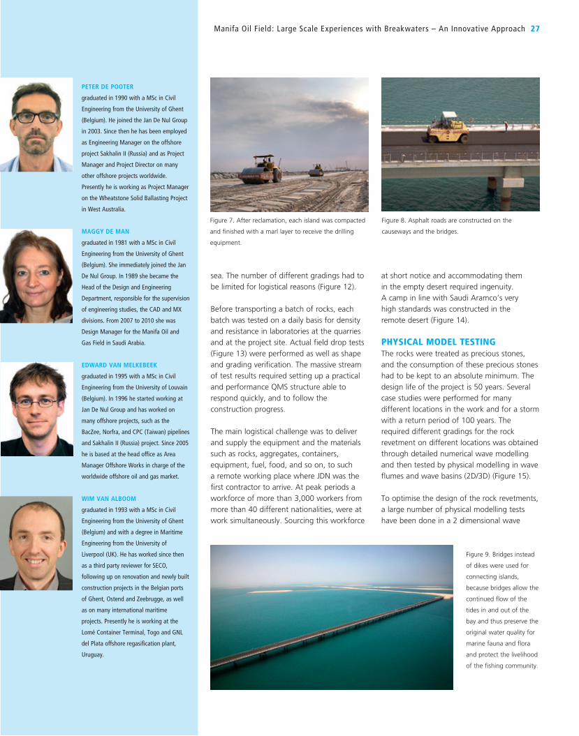
Figure 8. Asphalt roads are constructed on the
causeways and the bridges.
Figure 9. Bridges instead
of dikes were used for
connecting islands,
because bridges allow the
continued flow of the
tides in and out of the
bay and thus preserve the
original water quality for
marine fauna and flora
and protect the livelihood
of the fishing community.
Figure 7. After reclamation, each island was compacted
and finished with a marl layer to receive the drilling
equipment.
particular shallow water conditions, where
waves are depth-limited and empirical
damage formulae fall outside of their
applicable ranges. The amount of model test
results made available in the project
constitutes an important database that may
well complement and expand the current
state of the art.
In a 3-Dimensional wave basin at DHI in
Denmark, the corner of the islands and bridge
head sections have been tested, to check the
stability of the gradings under a 3D wave
attack. Again, armour damage has been
investigated by expressing the number of
displaced zones relative to the total amount
of rock in a particular zone. In order to
understand the particular 3D situation in
combination with angled wave attack, due
distinction was made between different areas
on the slopes (hence the different colour
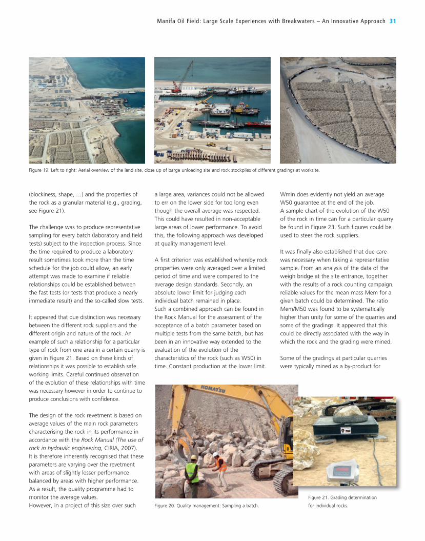
bands in Figure 18). The approach allowed
better localisation of problem areas and hence
directing the efforts towards where they were
needed. Starting from the extensive database
of the physical model results, a final task then
consisted in making sure that the design in
the real world was consistent with the model.
The numerically determined design wave
conditions over the vast project area have
been divided into areas of similar parameters
(grouping), which could then be assimilated
with one or more particular model test and
type of revetment design.
flume at the University of Ghent. Also at DHI
in Denmark and Sogreah in France additional
testing has been done. Several scales were
used in practice. Tests were performed by
gradually increasing the wave attack up until
and somewhat further than the design
conditions in order to allow a judgement on
the robustness of the design.
The size of the armour has been determined
in order to limit damage to allowable
percentages. Damage was hereby expressed
as the relative number of rocks that have
been moved during a design storm out of
their specific location on the revetment.
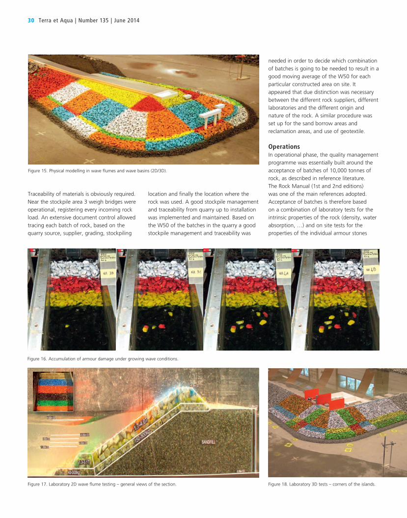
Extensive use was made of coloured scale
model armour in order to easily visualise the
evolution of damage. An example of the way
the armour damage could hence easily be
observed is given in Figure 16.
The heights of the crests have been
determined for an overtopping quantity of
2 l/m/sec. With respect to the overtopping
phenomena, a number of important
parameters have thoroughly been discussed
during the design phase. These include the
influence of the storm duration, the
correlation between high water levels and
design waves, the location where the
overtopping volume is measured, the width of
the crest, angled wave attack, the occurrence
probability of the overtopping criterion, scale
effects.
In particular cross sections, the breakwater
was topped by a wave retaining wall (Figure
17). Apart from measuring the overtopping
over the wall, the installation of pressure
transducers on the model wall allowed for
high frequency registration of wave induced
pressures. These important pressures were
compared to existing formulations available in
literature and could then be used to further
develop the strength design of the crest wall
element.
Every grading and every slope angle has been
tested. Also the toe stability has been
optimised by physical modelling. Physical
modelling proved to be helpful in some of the
28 Terra et Aqua | Number 135 | June 2014
Figure 11. Extra-long reach excavators, dump trucks,
wheel loaders, bulldozers, compactors, rollers and
concrete mixers at work.
Figure 10. Eleven dredgers as well as auxiliary vessels varying from tugboats, multicats, crew vessels, and fuel vessels and 40 barges and pontoons were deployed.
quarry is located some 600 km inland from
the coast, the closest 50 km. A traffic
management plan was set up in coordination
with the Client and the Saudi Authorities to
safely guide the trailers to the site. Rocks from
Oman quarries were transported to Manifa
over water. Some 12 million tonnes of rock of
6 different gradings were transported to the
site. Daily 400 trucks and trailers were
received and offloaded on the stockpile areas
(see Figure 19) and the rock loading jetties.
QUALITY MANAGEMENT SYSTEMTo guarantee the quality of the materials used
in the work, as well as the construction itself,
an extensive Quality Management System
(QMS), based on internationally accepted ISO
standards, was introduced, in close
coordination with Client and Suppliers. The
QMS has been set up in line with the JDN
Group Corporate Quality Management System
based on ISO 9001. A team of more than
30 quality inspectors was responsible for the
implementation, follow-up and constant
improvement of this QMS. An important part
of the QMS is internal audits, of which 13
have been executed, and these internal audits
are an indispensable tool to continuously
correct the quality system where necessary.
Besides Method Statements and Procedures,
the QMS requires working with materials with
confirmed quality complying with the project
specifications. Quality control on the
construction materials is an important part of
the daily site activities. Project specific tests
and inspections were identified and were
performed on sand materials, aggregate
materials, rock materials, geotextile, cement
and concrete, base course materials, marl,
asphalt aggregates, steel rebars, tubular steel
piles, fibre glass products, coating and
welding (Figure 20).
Three fully equipped site laboratories were
constructed to be able to follow and perform
the considerable amount of tests. About
7,000 individual lab tests were concluded
during the execution period of the project.
Given the remote location of the project and
the necessity to be able to correct and
interfere immediately in case of negative
trends in the test results, the installation and
operation of the site laboratories proved to be
a cost-effective approach.
Manifa Oil Field : Large Scale Experiences with Breakwaters – An Innovative Approach 29
ROCK REVETMENTThe entire work area covered not less than
80 km2. The logistical co-ordination and
transport over land and over water of
construction materials and equipment was one
of the biggest challenges of the project. In total
121 km of rock revetment was installed. This
whole project was about rock and its logistical
arrangements to get the required quantity of
rock within the required quality, timely on the
stockpiles and on the different worksites.
Six quarries were used, spread out over the
desert in eastern Saudi Arabia. The furthest
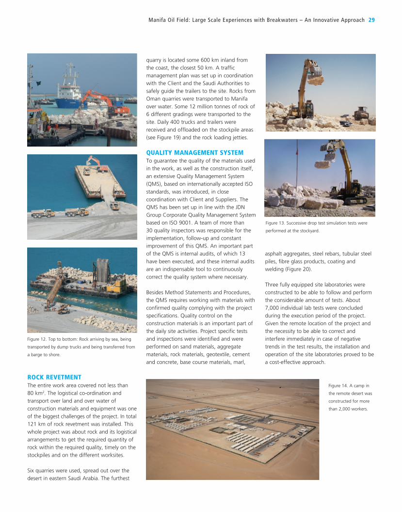
Figure 14. A camp in
the remote desert was
constructed for more
than 2,000 workers.
Figure 13. Successive drop test simulation tests were
performed at the stockyard.
Figure 12. Top to bottom: Rock arriving by sea, being
transported by dump trucks and being transferred from
a barge to shore.
30 Terra et Aqua | Number 135 | June 2014
needed in order to decide which combination
of batches is going to be needed to result in a
good moving average of the W50 for each
particular constructed area on site. It
appeared that due distinction was necessary
between the different rock suppliers, different
laboratories and the different origin and
nature of the rock. A similar procedure was
set up for the sand borrow areas and
reclamation areas, and use of geotextile.
OperationsIn operational phase, the quality management
programme was essentially built around the
acceptance of batches of 10,000 tonnes of
rock, as described in reference literature.
The Rock Manual (1st and 2nd editions)
was one of the main references adopted.
Acceptance of batches is therefore based
on a combination of laboratory tests for the
intrinsic properties of the rock (density, water
absorption, …) and on site tests for the
properties of the individual armour stones
location and finally the location where the
rock was used. A good stockpile management
and traceability from quarry up to installation
was implemented and maintained. Based on
the W50 of the batches in the quarry a good
stockpile management and traceability was
Traceability of materials is obviously required.
Near the stockpile area 3 weigh bridges were
operational, registering every incoming rock
load. An extensive document control allowed
tracing each batch of rock, based on the
quarry source, supplier, grading, stockpiling
Figure 17. Laboratory 2D wave flume testing – general views of the section. Figure 18. Laboratory 3D tests – corners of the islands.
Figure 16. Accumulation of armour damage under growing wave conditions.
Figure 15. Physical modelling in wave flumes and wave basins (2D/3D).
(blockiness, shape, …) and the properties of
the rock as a granular material (e.g., grading,
see Figure 21).
The challenge was to produce representative
sampling for every batch (laboratory and field
tests) subject to the inspection process. Since
the time required to produce a laboratory
result sometimes took more than the time
schedule for the job could allow, an early
attempt was made to examine if reliable
relationships could be established between
the fast tests (or tests that produce a nearly
immediate result) and the so-called slow tests.
It appeared that due distinction was necessary
between the different rock suppliers and the
different origin and nature of the rock. An
example of such a relationship for a particular
type of rock from one area in a certain quarry is
given in Figure 21. Based on these kinds of
relationships it was possible to establish safe
working limits. Careful continued observation
of the evolution of these relationships with time
was necessary however in order to continue to
produce conclusions with confidence.
The design of the rock revetment is based on
average values of the main rock parameters
characterising the rock in its performance in
accordance with the Rock Manual (The use of rock in hydraulic engineering, CIRIA, 2007).
It is therefore inherently recognised that these
parameters are varying over the revetment
with areas of slightly lesser performance
balanced by areas with higher performance.
As a result, the quality programme had to
monitor the average values.
However, in a project of this size over such
a large area, variances could not be allowed
to err on the lower side for too long even
though the overall average was respected.
This could have resulted in non-acceptable
large areas of lower performance. To avoid
this, the following approach was developed
at quality management level.
A first criterion was established whereby rock
properties were only averaged over a limited
period of time and were compared to the
average design standards. Secondly, an
absolute lower limit for judging each
individual batch remained in place.
Such a combined approach can be found in
the Rock Manual for the assessment of the
acceptance of a batch parameter based on
multiple tests from the same batch, but has
been in an innovative way extended to the
evaluation of the evolution of the
characteristics of the rock (such as W50) in
time. Constant production at the lower limit.
Wmin does evidently not yield an average
W50 guarantee at the end of the job.
A sample chart of the evolution of the W50
of the rock in time can for a particular quarry
be found in Figure 23. Such figures could be
used to steer the rock suppliers.
It was finally also established that due care
was necessary when taking a representative
sample. From an analysis of the data of the
weigh bridge at the site entrance, together
with the results of a rock counting campaign,
reliable values for the mean mass Mem for a
given batch could be determined. The ratio
Mem/M50 was found to be systematically
higher than unity for some of the quarries and
some of the gradings. It appeared that this
could be directly associated with the way in
which the rock and the grading were mined.
Some of the gradings at particular quarries
were typically mined as a by-product for
Manifa Oil Field : Large Scale Experiences with Breakwaters – An Innovative Approach 31
Figure 20. Quality management: Sampling a batch.
Figure 21. Grading determination
for individual rocks.
Figure 19. Left to right: Aerial overview of the land site, close up of barge unloading site and rock stockpiles of different gradings at worksite.

32 Terra et Aqua | Number 135 | June 2014
another quarry activity; other gradings were
clearly the main purpose of the quarry activity.
It appeared to affect to an important extent
the way a representative sample was taken in
the quarry. An idea of quarry mining activity is
given in Figure 24.
Rock degradationThe lifetime of the structure being well
specified, a systematic approach was adopted
with respect to possible causes of degradation
of the rock with time. Probably for the first
time, the provisions for reduction of the W50
during the lifetime as detailed in the Rock
Manual version 2007 were applied on such a
big scale. The design gradings of the job were
upgraded in order to cope with the natural
degradation of the rock once it is installed on
the slopes.
Before installation on the slope, rock typically
underwent a considerable amount of
manipulations. Mining at the quarry, transport
to site, delivery on site, transfer to an island,
offloading … may all be sources of successive
minor and major breakage of rock. In order to
quantify the weight loss caused by an
important amount of manipulations, a series
of successive drop tests was organised. This
allowed having a good idea on the weight
loss as a function of the number of
manipulations.
CONCLUSIONS
Several challenges presented themselves in
the execution of this major project in the
Kingdom of Saudi Arabia. First of all, the
location is critically complex. The shallow
waters of the Manifa Oil Field made it
impossible to use common offshore oil drilling
platforms and an innovative solution of
building oil drilling islands connected by
causeways was designed. Shallow waters
however demand ships with a limited
draught.
Rock was obviously the key player in the
success of this project: Although rocks were
mainly purchased in the Kingdom of Saudi
Arabia at several quarries, up to 600
kilometres inland from the worksite, more
was needed. The high demand for rock on
the worksite meant that rocks from quarries
in Oman were transported to Manifa by sea.
This demanded that a practical and well
thought-out Quality Management System be
set up in time and in close cooperation with
all parties involved, i.e., the design and
engineering team, the construction team, the
QAQC department, and the Client. The initial
costs and efforts for setting up a well-
functioning QMS are substantial but are easily
recovered in the long run during the project.
A large number of physical model tests were
conducted and this permitted optimising the
rock revetment design to a large extent –
which was critical. In an innovative way, a
relation between specific rock parameters was
identified. This was helpful in early acceptance
of the materials before arrival on site.
In addition, a big logistical challenge was to
deliver and supply the equipment and the
materials such as rocks, aggregates,
containers, equipment, fuel, food, and so on,
to such a remote working place. A workforce
of – at peak periods – more than 3,000
workers from more than 40 different
nationalities, had to be sourced in a short
notice and had to be accommodated.
All in all, an end product of good quality was
the result of the intentional effort, intelligent
guidance and skillful execution by the entire
workforce – the design and engineering team,
construction team, QAQC department and
the Client.Figure 24. Typical blasting activity at one of the quarries
which was used.
Figure 22. May 2008 Correlation chart density vs water absorption. Figure 23. December 2008 batch W50 evolution.