managing complexity of enterprise information systems · managing complexity of enterprise...
TRANSCRIPT
Managing Complexity ofManaging Complexity ofEnterprise Information SystemsEnterprise Information Systems
International Conference on Enterprise Information Systems14-17 April 2004, Porto, Portugal
Keynote Presentation
Leszek A. MaciaszekMacquarie University, Sydney, Australia
www.comp.mq.edu.au/~leszek© L.A.Maciaszek
© L.Maciaszek© L.Maciaszek ICEIS'04 PortoICEIS'04 Porto 22
Main pointsMain pointsMeasurably-supportable systemsSupportable system → dependency metricsArchitecture (hierarchy) that minimizes (potential) dependencies Dependencies on classes, messages, events, inheritanceProactive approach (architecture →implementation) and reactive approach(implementation → architecture)Two aims of reactive approach:• Conformance to the architecture• Comparison of different implementations
Global supportability metrics (fuzzy logic?)The issue of project management and availability of managerial tools

© L.Maciaszek© L.Maciaszek ICEIS'04 PortoICEIS'04 Porto 33
ReferencesReferencesMaciaszek, L.A. (2001): Requirements Analysis and System Design. Developing Information Systems with UML, Addison-Wesley, 378p. {translated to Chinese, Russian and Italian} Maciaszek, L.A. (2004): Requirements Analysis and Systems Design, 2nd ed., Addison-Wesley, ~630p. (to appear Sept 2004)• http://www.comp.mq.edu.au/books/rasd2ed/
Maciaszek, L.A. and Liong, B.L. (2004): Practical Software Engineering. A Case-Study Approach, Addison-Wesley, 829p. (to appear May 2004)• http://www.comp.mq.edu.au/books/pse/
© L.Maciaszek© L.Maciaszek ICEIS'04 PortoICEIS'04 Porto 44
The trouble with a good many of us is that we come to a The trouble with a good many of us is that we come to a conclusion before we arrive at the end. (F.J. Mills)conclusion before we arrive at the end. (F.J. Mills)
Hierarchical structures reduce complexity (Herb Simon, 1962)• complex – made up of a large number of parts that interact
in a non-simple wayA structure is stable if cohesion is strong and coupling low (Larry Constantine, 1974)• cohesion – intra-module communication• coupling – inter-module interaction
Only what is hidden can be changed without risk (David Parnas, 1972)Separation of concerns leads to standard architectures (Ernst Denert, 1991)An evolving system increases its complexity unless work is done to reduce it (Meir Lehman)
© L.Maciaszek© L.Maciaszek ICEIS'04 PortoICEIS'04 Porto 55
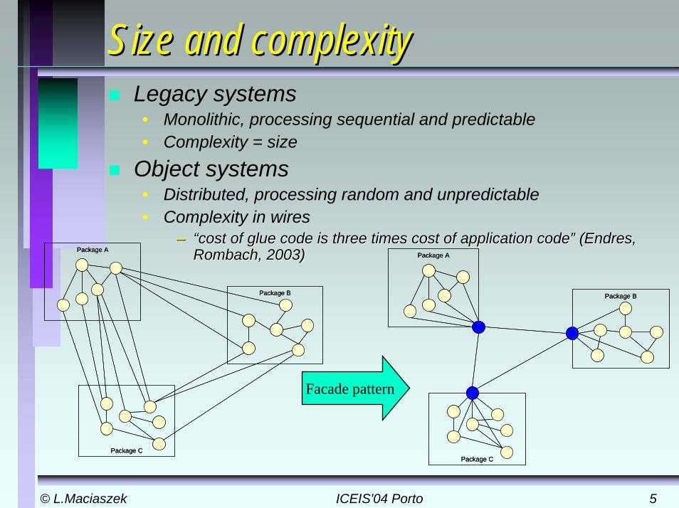
Size and complexitySize and complexityLegacy systems• Monolithic, processing sequential and predictable• Complexity = size
Object systems• Distributed, processing random and unpredictable• Complexity in wires
–– “cost of glue code is three times cost of application code” (“cost of glue code is three times cost of application code” (EndresEndres, , RombachRombach, 2003), 2003)Package A
Package B
Package C
Package A
Package B
Package C
Package A
Package B
Package C
Package A
Package B
Package C
Facade pattern
© L.Maciaszek© L.Maciaszek ICEIS'04 PortoICEIS'04 Porto 66
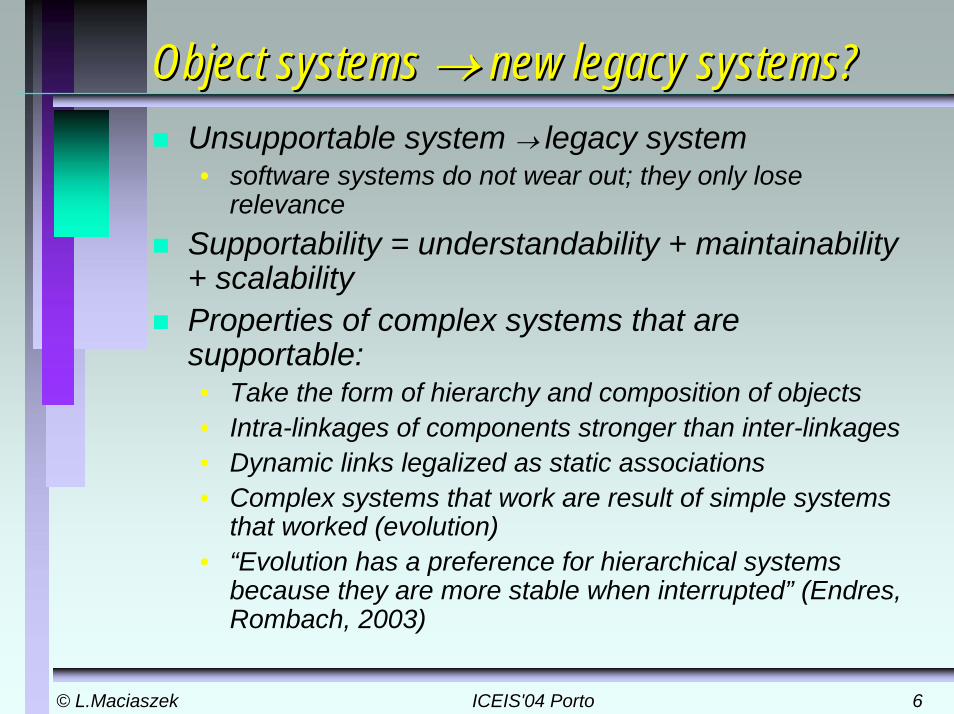
Object systemsObject systems →→ newnew legacy systems?legacy systems?Unsupportable system → legacy system• software systems do not wear out; they only lose
relevanceSupportability = understandability + maintainability+ scalabilityProperties of complex systems that are supportable:• Take the form of hierarchy and composition of objects • Intra-linkages of components stronger than inter-linkages • Dynamic links legalized as static associations• Complex systems that work are result of simple systems
that worked (evolution)• “Evolution has a preference for hierarchical systems
because they are more stable when interrupted” (Endres, Rombach, 2003)
© L.Maciaszek© L.Maciaszek ICEIS'04 PortoICEIS'04 Porto 77
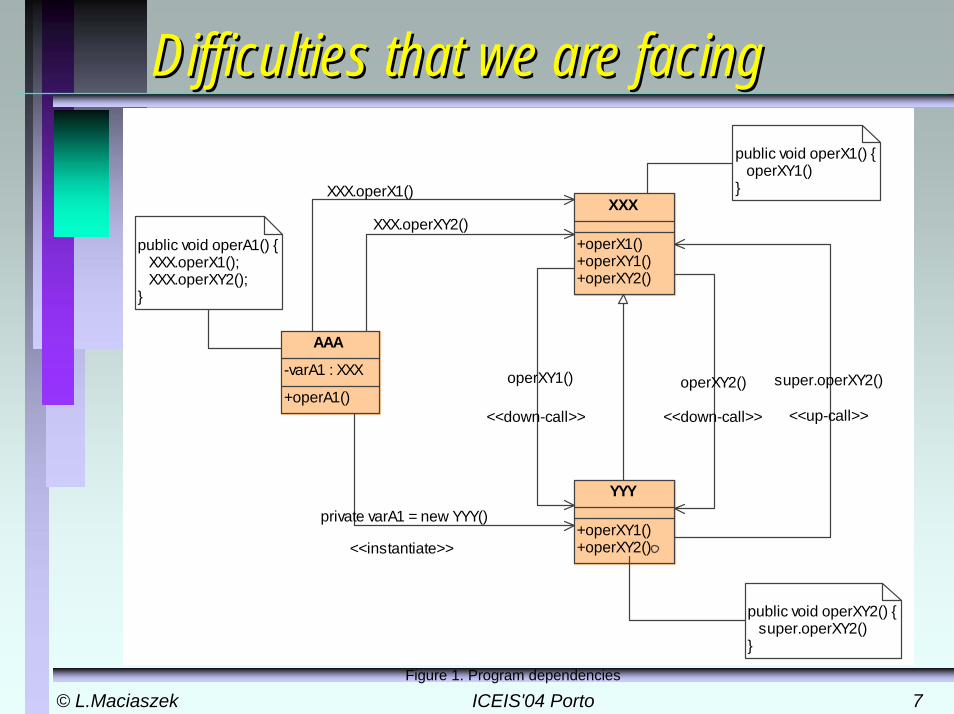
Difficulties that we are facingDifficulties that we are facing
public void operXY2() {��� super.operXY2()���}
public void operX1() {� operXY1()�}
public void operA1() {� XXX.operX1();� XXX.operXY2();�}
XXX
+operX1()+operXY1()+operXY2()
YYY
+operXY1()+operXY2()
AAA
-varA1 : XXX
+operA1()super.operXY2()
<<up-call>>
XXX.operX1()
operXY1()
<<down-call>>
operXY2()
<<down-call>>
private varA1 = new YYY()
<<instantiate>>
XXX.operXY2()
Figure 1. Program dependencies
© L.Maciaszek© L.Maciaszek ICEIS'04 PortoICEIS'04 Porto 88
Application design objectivesApplication design objectivesa hierarchical layering of software modules that reduces complexity and enhances understandability of module dependencies by disallowing direct object intercommunication between non-neighboring layers, and an enforcement of programming standards that make module dependencies visible in compile-time program structures and that forbid muddy programming solutions utilizing just run-time program structures
© L.Maciaszek© L.Maciaszek ICEIS'04 PortoICEIS'04 Porto 99
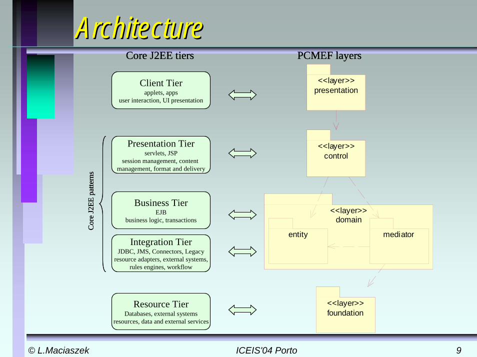
ArchiteArchitecturecture
presentation<<layer>>
control<<layer>>
domain<<layer>>
entity mediator
foundation<<layer>>
Client Tierapplets, apps
user interaction, UI presentation
Presentation Tierservlets, JSP
session management, content management, format and delivery
Business TierEJB
business logic, transactions
Integration TierJDBC, JMS, Connectors, Legacy
resource adapters, external systems,rules engines, workflow
Resource TierDatabases, external systems
resources, data and external services
Cor
e J2
EE p
atte
rns
Core J2EE tiers PCMEF layers
© L.Maciaszek© L.Maciaszek ICEIS'04 PortoICEIS'04 Porto 1010
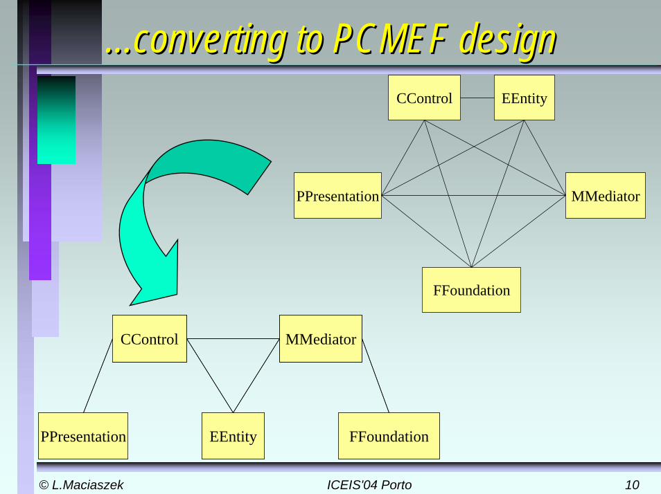
...converting to PCMEF design...converting to PCMEF design
CControl
EEntityPPresentation FFoundation
MMediatorCControl
EEntityPPresentation FFoundation
MMediator
CControl EEntity
PPresentation
FFoundation
MMediator
© L.Maciaszek© L.Maciaszek ICEIS'04 PortoICEIS'04 Porto 1111
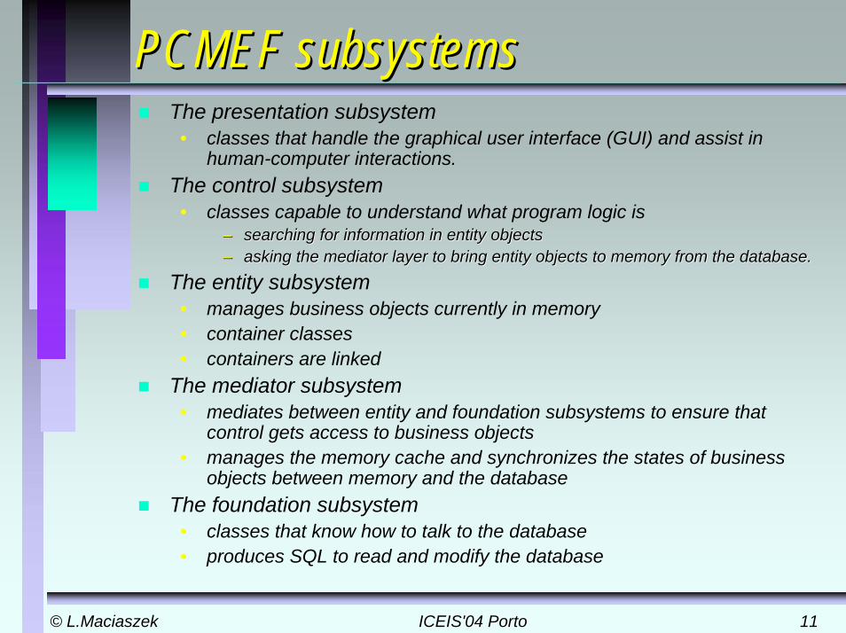
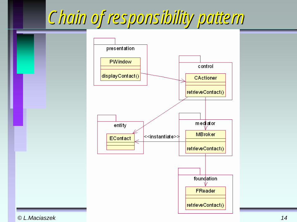
PCMEF subsystemsPCMEF subsystemsThe presentation subsystem
• classes that handle the graphical user interface (GUI) and assist in human-computer interactions.
The control subsystem • classes capable to understand what program logic is
–– searching for information in entity objectssearching for information in entity objects–– asking the mediator layer to bring entity objects to memory fromasking the mediator layer to bring entity objects to memory from the database.the database.
The entity subsystem • manages business objects currently in memory• container classes • containers are linked
The mediator subsystem • mediates between entity and foundation subsystems to ensure that
control gets access to business objects• manages the memory cache and synchronizes the states of business
objects between memory and the databaseThe foundation subsystem
• classes that know how to talk to the database• produces SQL to read and modify the database
© L.Maciaszek© L.Maciaszek ICEIS'04 PortoICEIS'04 Porto 1212
PCMEFPCMEF patternspatternsPCMEF architecture is based on some well-known design patterns and on few new patterns specific to PCMEF Main source of patterns for PCMEF are • GoF (Gang of Four – [GAMM1995]), • PEAA (Patterns of Enterprise
Application Architecture –[FOWL2003])
• Core J2EE [ALUR2003]Patterns particularly useful include: MVC, Façade, Abstract Factory, Chain of Responsibility, Observer, Mediator, Identity Map, Data Mapper, Lazy Load, OID Proxy.
© L.Maciaszek© L.Maciaszek ICEIS'04 PortoICEIS'04 Porto 1313
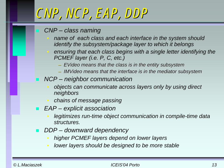
CNP, NCP, EAP, DDPCNP, NCP, EAP, DDPCNP – class naming• name of each class and each interface in the system should
identify the subsystem/package layer to which it belongs• ensuring that each class begins with a single letter identifying the
PCMEF layer (i.e. P, C, etc.)–– EVideoEVideo means that the class is in the entity subsystemmeans that the class is in the entity subsystem–– IMVideoIMVideo means that the interface is in the mediator subsystemmeans that the interface is in the mediator subsystem
NCP – neighbor communication• objects can communicate across layers only by using direct
neighbors• chains of message passing
EAP – explicit association • legitimizes run-time object communication in compile-time data
structures.DDP – downward dependency • higher PCMEF layers depend on lower layers• lower layers should be designed to be more stable
© L.Maciaszek© L.Maciaszek ICEIS'04 PortoICEIS'04 Porto 1414
Chain of responsibility patternChain of responsibility pattern
© L.Maciaszek© L.Maciaszek ICEIS'04 PortoICEIS'04 Porto 1515
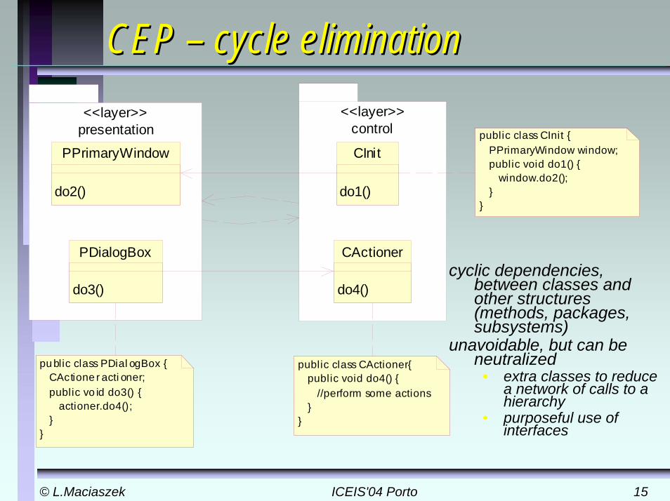
CEP CEP –– cycle eliminationcycle elimination
cyclic dependencies, between classes and other structures (methods, packages, subsystems)
unavoidable, but can be neutralized
• extra classes to reduce a network of calls to a hierarchy
• purposeful use of interfaces
public class CActioner{ public void do4() { //perform some actions }}
presentation<<layer>>
control<<layer>>
public class CInit { PPrimaryWindow window; public void do1() { window.do2(); }}
pu blic class PDial ogBox { CActione r acti oner; public vo id do3() { actioner.do4(); }}
CActioner
do4()
PDialogBox
do3()
PPrimaryWindow
do2()
CInit
do1()

© L.Maciaszek© L.Maciaszek ICEIS'04 PortoICEIS'04 Porto 1616
CEPCEP
presentation<<layer>> control
<<layer>>
PPrimaryWindow
do2()
publ ic class CIni t { ICPresenter presenter; publ ic void do1(){ presenter.do2(); }}
publ ic class PPrimaryWindowimplements control.ICPresenter { publ ic void do2() { //implementation code }}
publ ic interface PControl ler { publ ic void do2();}
ICPresenter
do2()
CInit
do1()
<<uses>>
CActioner
do4()
PDialogBox
do3()
© L.Maciaszek© L.Maciaszek ICEIS'04 PortoICEIS'04 Porto 1717
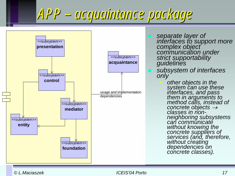
APP APP –– acquaintance packageacquaintance packageseparate layer of interfaces to support more complex object communication under strict supportability guidelinessubsystem of interfaces only• other objects in the
system can use these interfaces, and pass them in arguments to method calls, instead of concrete objects →classes in non-neighboring subsystems can communicate without knowing the concrete suppliers of services (and, therefore, without creating dependencies on concrete classes).
<<subsystem>>acquaintance
<<subsystem>>presentation
<<subsystem>>mediator
<<subsystem>>entity
<<subsystem>>control
<<subsystem>>foundation
usage and implementation �dependencies
© L.Maciaszek© L.Maciaszek ICEIS'04 PortoICEIS'04 Porto 1818
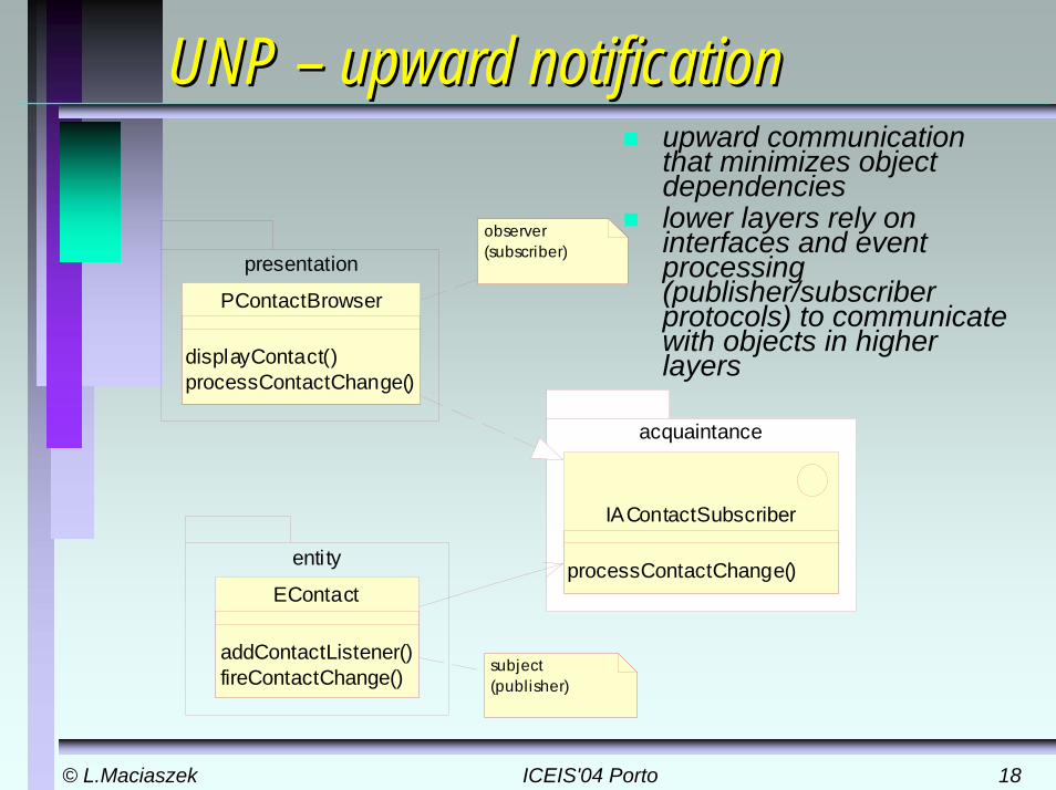
UNP UNP –– upward notificationupward notificationupward communication that minimizes object dependencieslower layers rely on interfaces and event processing (publisher/subscriber protocols) to communicate with objects in higher layers
presentation
entity
PContactBrowser
displayContact()processContactChange()
acquaintance
EContact
addContactListener()fireContactChange()
IAContactSubscriber
processContactChange()
subject (publisher)
observer (subscriber)
© L.Maciaszek© L.Maciaszek ICEIS'04 PortoICEIS'04 Porto 1919
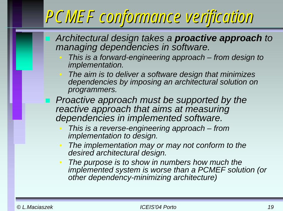
PCMEF conformance verificationPCMEF conformance verificationArchitectural design takes a proactive approach to managing dependencies in software. • This is a forward-engineering approach – from design to
implementation. • The aim is to deliver a software design that minimizes
dependencies by imposing an architectural solution on programmers.
Proactive approach must be supported by the reactive approach that aims at measuring dependencies in implemented software. • This is a reverse-engineering approach – from
implementation to design. • The implementation may or may not conform to the
desired architectural design.• The purpose is to show in numbers how much the
implemented system is worse than a PCMEF solution (or other dependency-minimizing architecture)

© L.Maciaszek© L.Maciaszek ICEIS'04 PortoICEIS'04 Porto 2020
CCDCCDDEFINITION: Cumulative Class Dependency (CCD) is the total supportability cost over all classes Ci{i=1,…,n) in a system of the number of classes Cj(j<=1,…,n) to be potentially changed in order to modify each class Ci.
Calculation of CCD assumes adherence to the architectural framework. If the framework is found to be broken, the CCD is calculated as if a class can depend on any other class in the system.• probability theory method - the combinations counting rule • The CCD is the number of different combinations of pairs of
dependent classes which can be formed from the total number of classes in the design multiplied by 2 (cycles)
2)!2(!2
!2 ×
−=
nnCCDn
© L.Maciaszek© L.Maciaszek ICEIS'04 PortoICEIS'04 Porto 2121
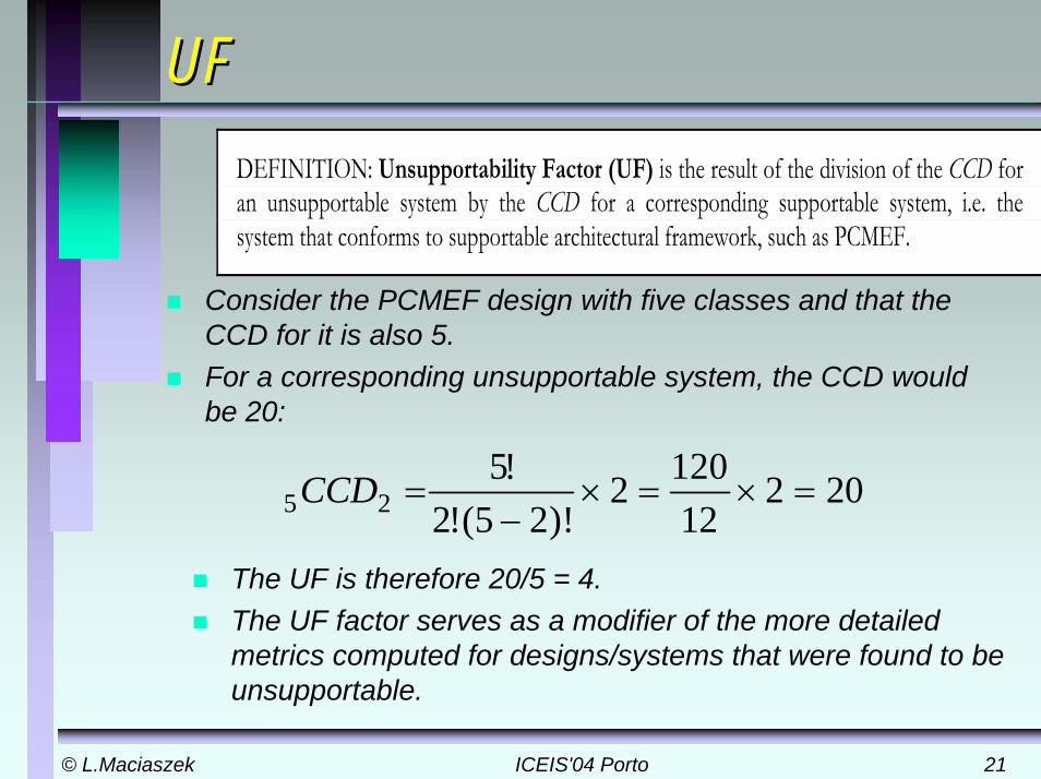
UFUF
Consider the PCMEF design with five classes and that the CCD for it is also 5. For a corresponding unsupportable system, the CCD would be 20:
DEFINITION: Unsupportability Factor (UF) is the result of the division of the CCD for an unsupportable system by the CCD for a corresponding supportable system, i.e. the system that conforms to supportable architectural framework, such as PCMEF.
The UF is therefore 20/5 = 4. The UF factor serves as a modifier of the more detailed metrics computed for designs/systems that were found to be unsupportable.
20212
1202)!25(!2
!525 =×=×
−=CCD
© L.Maciaszek© L.Maciaszek ICEIS'04 PortoICEIS'04 Porto 2222
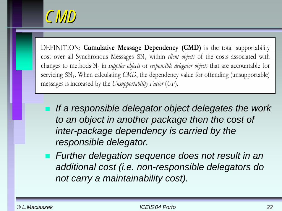
CMDCMDDEFINITION: Cumulative Message Dependency (CMD) is the total supportability cost over all Synchronous Messages SMi within client objects of the costs associated with changes to methods Mj in supplier objects or responsible delegator objects that are accountable for servicing SMi. When calculating CMD, the dependency value for offending (unsupportable) messages is increased by the Unsupportability Factor (UF).
If a responsible delegator object delegates the work to an object in another package then the cost of inter-package dependency is carried by the responsible delegator. Further delegation sequence does not result in an additional cost (i.e. non-responsible delegators do not carry a maintainability cost).
© L.Maciaszek© L.Maciaszek ICEIS'04 PortoICEIS'04 Porto 2323
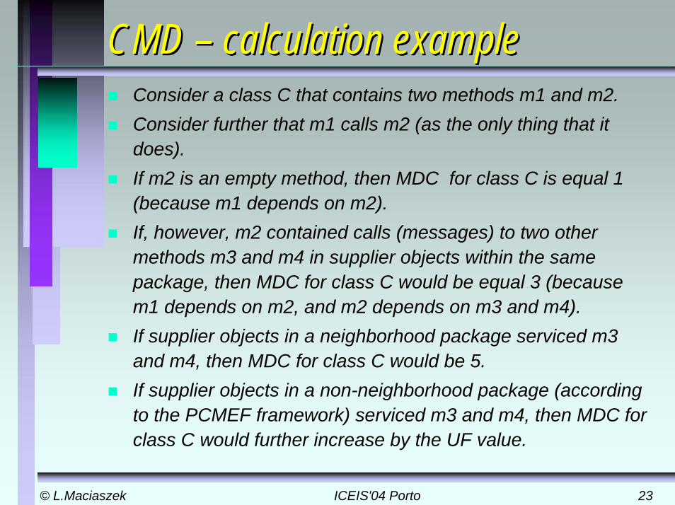
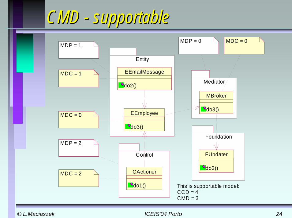
CMD CMD –– calculation examplecalculation exampleConsider a class C that contains two methods m1 and m2. Consider further that m1 calls m2 (as the only thing that it does). If m2 is an empty method, then MDC for class C is equal 1 (because m1 depends on m2). If, however, m2 contained calls (messages) to two other methods m3 and m4 in supplier objects within the same package, then MDC for class C would be equal 3 (because m1 depends on m2, and m2 depends on m3 and m4). If supplier objects in a neighborhood package serviced m3 and m4, then MDC for class C would be 5. If supplier objects in a non-neighborhood package (according to the PCMEF framework) serviced m3 and m4, then MDC for class C would further increase by the UF value.
© L.Maciaszek© L.Maciaszek ICEIS'04 PortoICEIS'04 Porto 2424
CMD CMD -- supportablesupportable
Entity
Control
EEmailMessage
do2()
EEmployee
do3()
MDC = 1
MDC = 0
MDC = 2
MDP = 1
MDP = 2
CActioner
do1()
Mediator
MBroker
do3()
Foundation
FUpdater
do3()
MDP = 0 MDC = 0
This is supportable model:CCD = 4CMD = 3

© L.Maciaszek© L.Maciaszek ICEIS'04 PortoICEIS'04 Porto 2525
CMD CMD -- unsupportableunsupportable
Entity Control
EEmailMessage
do2()
EEmployee
do3()
MDC = 1
MDC = 0
MDC = 2
MDP = 1
MDP = 2
CActioner
do1()
Foundation
FUpdater
do3()This is unsupportable model:CCD = 12UF = 3CMD = 1+(2*3) = 7
© L.Maciaszek© L.Maciaszek ICEIS'04 PortoICEIS'04 Porto 2626
CEDCED
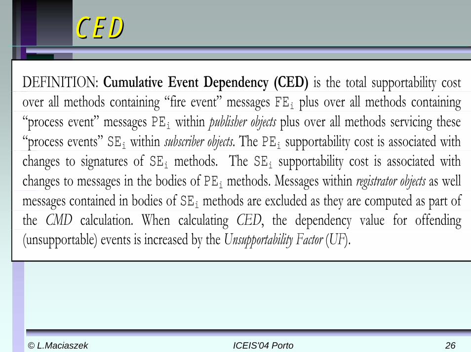
DEFINITION: Cumulative Event Dependency (CED) is the total supportability cost over all methods containing “fire event” messages FEi plus over all methods containing “process event” messages PEi within publisher objects plus over all methods servicing these “process events” SEi within subscriber objects. The PEi supportability cost is associated with changes to signatures of SEi methods. The SEi supportability cost is associated with changes to messages in the bodies of PEi methods. Messages within registrator objects as well messages contained in bodies of SEi methods are excluded as they are computed as part of the CMD calculation. When calculating CED, the dependency value for offending (unsupportable) events is increased by the Unsupportability Factor (UF).
© L.Maciaszek© L.Maciaszek ICEIS'04 PortoICEIS'04 Porto 2727
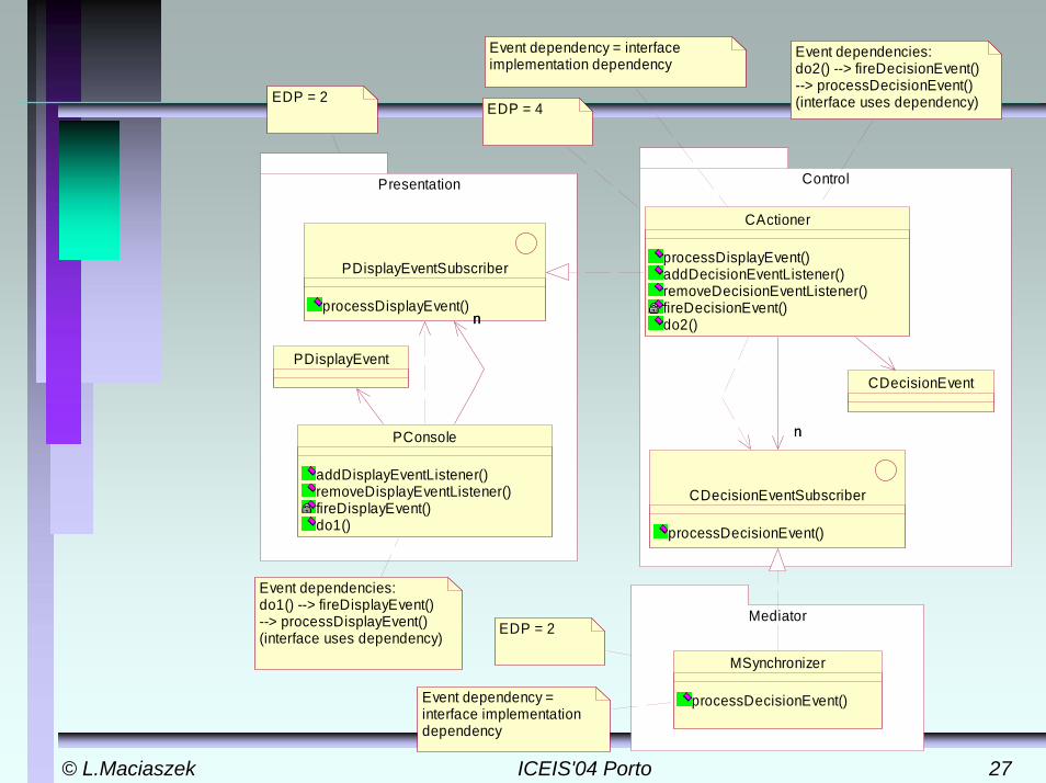
Presentation Control
Mediator
MSynchronizer
processDecisionEvent()
PDisplayEvent
PDisplayEventSubscriber
processDisplayEvent()
PConsole
addDisplayEventListener()removeDisplayEventListener()fireDisplayEvent()do1()
nn
CDecisionEventSubscriber
processDecisionEvent()
CDecisionEvent
CActioner
processDisplayEvent()addDecisionEventListener()removeDecisionEventListener()fireDecisionEvent()do2()
nn
Event dependencies:do1() --> fireDisplayEvent() --> processDisplayEvent()(interface uses dependency)
EDP = 2
Event dependency = interface implementation dependency
EDP = 4
Event dependency = interface implementation dependency
EDP = 2
Event dependencies:do2() --> fireDecisionEvent() --> processDecisionEvent()(interface uses dependency)
© L.Maciaszek© L.Maciaszek ICEIS'04 PortoICEIS'04 Porto 2828
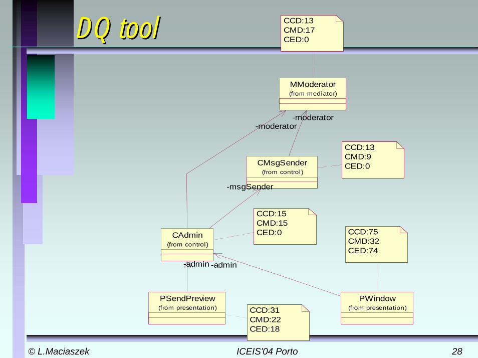
DQ toolDQ tool
CCD:15CMD:15CED:0
CCD:13CMD:9CED:0CMsgSender
(from control)
MModerator(from mediator)
-moderator
PSendPreview(from presentation)
CAdmin(from control)
-msgSender
-moderator
-admin
PWindow(from presentation)
-admin
CCD:75CMD:32CED:74
CCD:31CMD:22CED:18
CCD:13CMD:17CED:0
© L.Maciaszek© L.Maciaszek ICEIS'04 PortoICEIS'04 Porto 2929
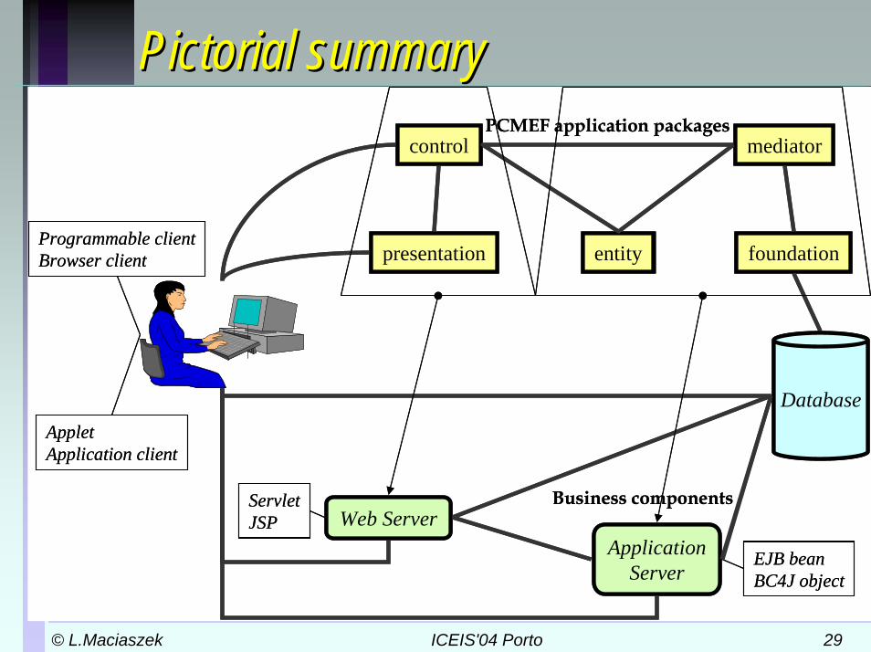
Pictorial summaryPictorial summarycontrol
entitypresentation foundation
mediatorPCMEF application packages
Programmable clientBrowser client
Database
Web ServerApplication
Server
AppletApplication client
Business componentsServletJSP
EJB beanBC4J object
control
entitypresentation foundation
mediatorPCMEF application packages
Programmable clientBrowser client
Database
Web ServerApplication
Server
AppletApplication client
Business componentsServletJSP
EJB beanBC4J object

© L.Maciaszek© L.Maciaszek ICEIS'04 PortoICEIS'04 Porto 3030
ConclusionConclusion –– let’s return to the naturelet’s return to the natureFor every complex problem there is a simple solution –that won't work [H.L. Mencken]
© L.Maciaszek© L.Maciaszek ICEIS'04 PortoICEIS'04 Porto 3131
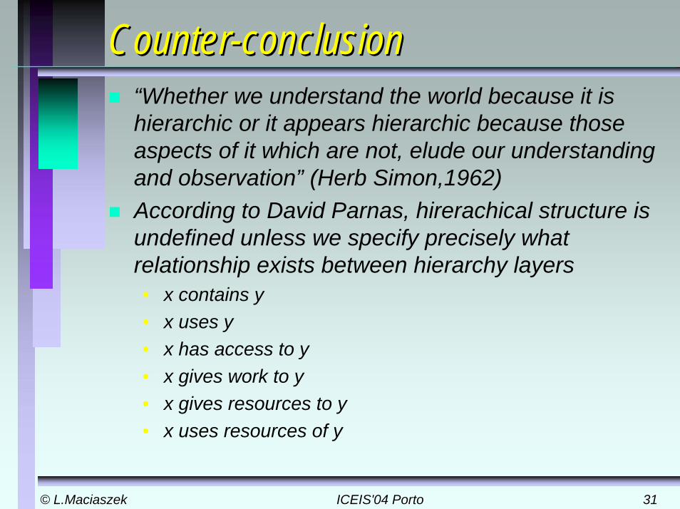
CounterCounter--conclusionconclusion“Whether we understand the world because it is hierarchic or it appears hierarchic because those aspects of it which are not, elude our understanding and observation” (Herb Simon,1962)According to David Parnas, hirerachical structure is undefined unless we specify precisely what relationship exists between hierarchy layers• x contains y• x uses y• x has access to y• x gives work to y• x gives resources to y• x uses resources of y
© L.Maciaszek© L.Maciaszek ICEIS'04 PortoICEIS'04 Porto 3232
Additional referencesAdditional referencesFOWLER, M. (1999): Refactoring. Improving the Design of Existing Code, Addison-Wesley, 431p.
FOWLER, M. (2003): Patterns of Enterprise Application Architecture, Addison-Wesley, 531p.
GAMMA, E. HELM, R. JOHNSON, R. and VLISSIDES, J. (1995): Design Patterns. Elements of Reusable Object-Oriented Software, Addison-Wesley, 395p.
LARMAN, C. (2002): Applying UML and Patterns. An Introduction to Object-Oriented Analysis and Design and the Unified Process, 2nd ed., Prentice-Hall, 627p.
MARTIN, R.C. (2003): Agile Software Development, Principles, Patterns, and Practices, Prentice-Hall, 529p.