maintenance schedules for ballast cleaning machine...
TRANSCRIPT

Page 1 of 21
GOVERNMENT OF INDIA MINISTRY OF RAILWAYS
MAINTENANCE SCHEDULES
FOR
BALLAST CLEANING MACHINE
(RM-80)
REPORT NO. TM -77
JANUARY- 2005
RESEARCH DESIGNS & STANDARDS ORGANISATION
LUCKNOW-226011

Page 2 of 17
PREFACE
Maintenance of On-Track Machine is a challenging task. Presently, about 345
On Track Machines are working over different zonal railways. Maintenance of these machines is being done by zonal railways with the assistance of local trade available, zonal track machine workshops, CPOH / Allahabad and RDSO/ Lucknow. With experience over the years, the railway engineers have developed adequate expertise in the maintenance of these machines. However, in absence of approved maintenance instructions, different maintenance practices have come into vogue. Therefore, it has become imperative to have a uniform maintenance standard throughout the Indian Railways. Provisional maintenance schedule manuals for Points and Crossing Tamping Machine (UNIMAT), Dynamic Track Stabilizer (DGS-62N), Shoulder Ballast Cleaning Machine (FRM-80), Ballast Regulating Machine (BRM), Points and Crossings Changing Machine (T-28), Plasser Quick Relaying System (PQRS), Multipurpose Tamping Machine (MP), Duomatic machine (DUO), Unomatic machine (UNO) , Track relaying train (TRT), and Continuous tamping machine (final) have been issued by RDSO. Provisional maintenance schedule manual for Ballast Cleaning Machine (BCM RM-80) was issued previously as report no.TM-23 vide letter no. TM/HM/15 dated 23-09-97. Present manual have been prepared after necessary amendment in provisional manual on the basis of experience and suggestions received from railways. It is hoped that this manual will be quite useful for the staff maintaining the machines in field. While every care has been taken to make the maintenance schedules quite exhaustive, there is always scope for further improvement. Suggestions from the railways in this regard will be welcome and may be sent to the undersigned.
SURENDRA KUMAR Executive Director/TMM RDSO/Lucknow-226011. JANUARY-2005

Page 3 of 17
EXPLANATORY NOTES
While preparing text of schedules for maintenance of Ballast Cleaning Machine (RM-80), the terms used and their meanings are explained below:
CHECK - Ensure a specific condition does or does not exist.
INSPECT - Look for damage and defects including breakage, distortion, cracks, corrosion and wear, Check for leaks, security and that all items are completed.
CHANGE - Fit new or overhauled or reconditioned part in place of old parts and missing parts.
OVERHAUL - Dismantle, examine, recondition or renew parts as necessary against given specifications, reassemble, inspect and test.

Page 4 of 17
INDEX
S.N. DESCRIPTION PAGE NO.
1. Schedule I
1
2. Schedule II
2
3. Schedule III
3
4. Schedule IV
4
5. Schedule V
5
6. Schedule VI
6
7. Schedule VII
7-8
8. Annexure –I
9-12
9. Annexure –II
13
10. Annexure –III
14
11. Annexure –IV
15
12. Annexure –V
16
13. Acknowledgement
17

Page 1 of 17
Schedule -- I
To be done daily
(Duration – Two hrs)
1. ENGINES
1. Check level of the lube oil and top up, if required. 2. Check fuel level and top up if required. 3. Check for any oil leakage from the fuel pump, injectors, fuel supply,
and return pipes. 4. Check engine oil pressure after warming up-
(a) at idle speed ( min. 1.5 kg/sq.cm ) (b) on rated speed ( min. 2.5 kg/sq.cm ).
5. Check & correct the tension of alternator V-belt. 6. Check the contamination indicators (pilot lamps) for dry type air filter.
7. Record the maximum engine temperature of the day. 8 Clean engines and their premises. 9 Check the functioning of engine clutch.
2. MACHINE GENERAL: 1. Check up oil level and top up both main gear boxes, if required. 2. Check hydraulic oil level in tank and top up if required 3. Check oil level of axle gear boxes and top up, if required. 4. Check oil level in vibration screen drum.
5. Check the corner roller lubrication. 6. Inspect wear plates on ascending side and change badly worn-out plates 7. Check proper locking of all units. 8. Check the function and condition of conveyor belt, belt tension, scrapers
of conveyors and look out for damages. 9. Check anti collision devise of waste conveyors. 10. Screening mesh should be checked in order to have proper sizes of ballast. 11. Check wear on ballast distribution chutes. 12. Check for any unusual sound from machine. 13. Check air brake system pressure. 14. Check for any air leakage. 15. Check leakage in hydraulic circuit and do needful. 16. Check tightness of cardon shaft bolts. 17. Check locking screws, round shaft chisel and do needful. 18. Drain air reservoirs after the day’s work 19. Record the max. hydraulic oil temperature of the day

Page 2 of 17
Schedule II
To be done after 50 engine hours
(Duration – One day)
1. ENGINES 1. Clean air cleaner element (outer) with 1.5 bar pressure of dry air. 2. Change oil in the wet type air filter. 3. Clean the fins of engines and air charge cooler. 4. Clean battery plug connections and apply petroleum jelly. 5. Check electrolyte level in batteries and specific gravity
[ minimum specific gravity = 1.24 ].
2. MACHINE GENERAL:
1. Check brake linkage and oil the pivots. 2. Check function of air oiler. 3. Check clearance of lifting roller disc below the rail head in lowered condition 4. Check function of hydraulic limit valve for track lifting and do needful 5. Check the wear of the turret drum area. 6. Check guide rollers of conveyor belts. 7. Check for any rubbing of hoses, loose clamping etc. and correct it. 8. Check the condition of the cutter chain and replace worn-out parts 9. Lubricate axle gear box flange cover of driving bogie with grease. 10. Lubricate screen guide plates with grease. 11. Lubricate lifting unit guide columns with grease 12. Lubricate rail clamp pivot pins with grease. 13. Lubricate roller clamp housing with grease. 14. Lubricate locking device pivots with grease. 15. Lubricate track lifting cylinder pivots with grease. 16. Lubricate all carden shafts with grease. 17. Lubricate bearings for main conveyor with grease. 18. Clean water separator . 19. Clean complete machine.

Page 3 of 17
Schedule III
To be done after 100 engine hours
(Duration – one day)
1. ENGINES 1. Clean fuel pre-filter (wire mesh). 2. Change the twin stage fuel filter element.
2. MACHINE GENERAL
1. Check oil level in turret drum. 2. Check all the idler rollers of conveyor for free rotation. 3. Check all brake linkages. 4. Check covering rubber of chain trough. 5. Check movement of sliding plate of chain trough. 6. Lubricate bogie pivot king pin with grease.

Page 4 of 17
Schedule IV
To be done after 200 engine hours
(Duration --Two days)
1. ENGINES
1. Change engine oil . 2. Change lub oil filters. 3. Check tappet clearances and adjust if required. 4. Check engine hoses for leakage and condition and do needful. 5. Grease clutch drive shaft bearings. 6. Check clutch fluid level in container.
2. MACHINE GENERAL 1. Check piston rings of axle gear box and change, if required 2. Check condition of roller disc clamp for lifting device and do needful. 3. Check system pressure for rated settings and adjust if necessary. 4. Check tightness of foundation bolts of brake cylinders. 5. Check all pressure controls for rated settings. 6. Inspect cooling coil for any breakage or leakage. 7. Check foundation and bracket bolts of compressor. 8. Check function of all limits switches. 9. Check up rubber element of torque plate suspension and do needful. 10. Check the excavation chain sprocket and change if required. 11. Clean breather filter of hydraulic oil tank. 12. Clean filter element of pneumatic system. 13. Clean alternator and check connections. 14. Clean the filters of axle gear box clutch. 15. Clean fins of hydraulic oil cooler. 16. Clean gear oil cooler. 17. Clean filter elements of main gear box. 18. Recondition/Replace the cutter bar. 19. Change oil in the oil chamber of tension cylinder. 20. Replace excavating fingers if required. 21. Remove bushes of axle gear box and check the condition of the piston ring
groove 22. Repair ballast screens. 23. Replace scraper shovel and intermediate links, if required. 24. Lubricate hand brake gear with grease. 25. Lubricate chain trough bearings with grease. 26. Change oil in the axle gear boxes and replace clutch filter. 27. Change oil in the main gear box. 28. Change oil in the main waste conveyor gear box.
Note:-- Item no. 10,15,16,17,23,26,27,28 will be done after 500 engine hrs.
Page 5 of 17
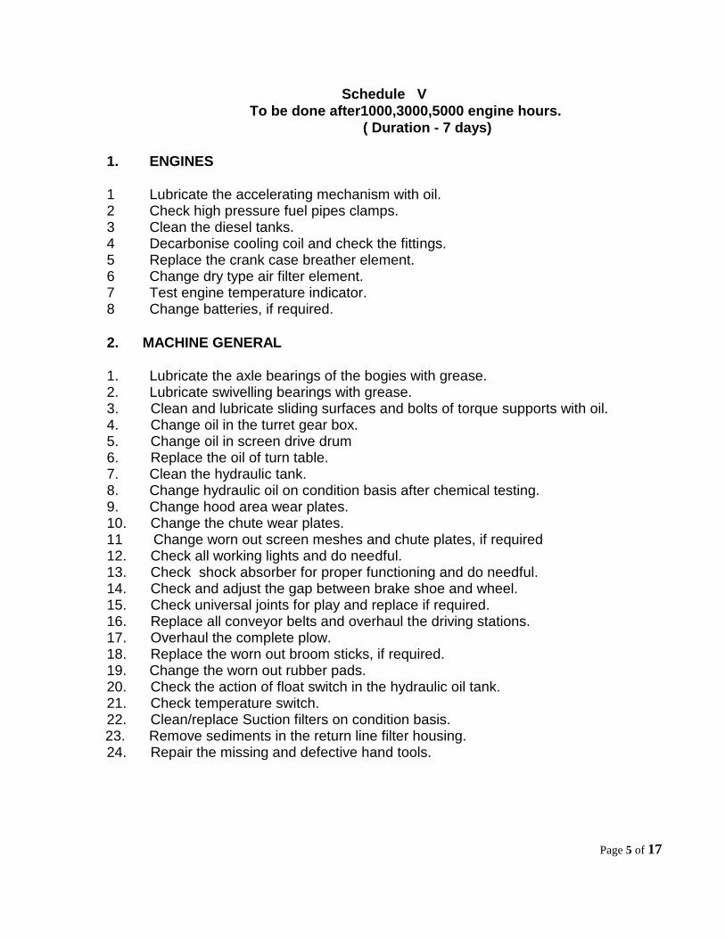
Schedule V
To be done after1000,3000,5000 engine hours.
( Duration - 7 days)
1. ENGINES
1 Lubricate the accelerating mechanism with oil. 2 Check high pressure fuel pipes clamps. 3 Clean the diesel tanks. 4 Decarbonise cooling coil and check the fittings. 5 Replace the crank case breather element. 6 Change dry type air filter element. 7 Test engine temperature indicator. 8 Change batteries, if required.
2. MACHINE GENERAL
1. Lubricate the axle bearings of the bogies with grease. 2. Lubricate swivelling bearings with grease. 3. Clean and lubricate sliding surfaces and bolts of torque supports with oil. 4. Change oil in the turret gear box. 5. Change oil in screen drive drum 6. Replace the oil of turn table. 7. Clean the hydraulic tank. 8. Change hydraulic oil on condition basis after chemical testing. 9. Change hood area wear plates. 10. Change the chute wear plates. 11 Change worn out screen meshes and chute plates, if required 12. Check all working lights and do needful. 13. Check shock absorber for proper functioning and do needful. 14. Check and adjust the gap between brake shoe and wheel. 15. Check universal joints for play and replace if required. 16. Replace all conveyor belts and overhaul the driving stations. 17. Overhaul the complete plow. 18. Replace the worn out broom sticks, if required. 19. Change the worn out rubber pads. 20. Check the action of float switch in the hydraulic oil tank. 21. Check temperature switch. 22. Clean/replace Suction filters on condition basis.
23. Remove sediments in the return line filter housing. 24. Repair the missing and defective hand tools.

Page 6 of 17
Schedule VI
(To be done after 2000, 4000 engine hours)
(45 days)
1. ENGINES
1. Check engine timing and do needful. 2. Check and clean air reservoir. 3. Check the air compressor. Overhaul if necessary. 4. Replace V-belts on condition basis. 5. Overhaul the alternator and starter. 6. Clean turbocharger and do needful. 7. Check anti vibration mountings of the engine and change, if required. 8. Calibrate the fuel injection pump. 9. Calibrate the fuel injectors.
2. MACHINE GENERAL
1. Paint the screen area & chain trough. 2. Check wheel tyre defects and do needful.

Page 7 of 17
Schedule VII
To be done after 6000 engine hours
(Duration-90 Days)
1. ENGINES 1. De-carbonise the engine heads. 2. Check crank shaft and cam shaft end play. 3. Overhaul the air compressor. 4. Change air inlet hoses. 5. Overhaul blower assembly. 6. Change all the high pressure fuel pipes, pipe clamp, flexible fuel hoses and
rubber hoses. 7. Overhaul turbo charger. 8. Change shaft seals and bearings of the clutch drive shaft assembly. 9. Check the exhaust manifold for any defect and clean the same. 10. Change shut down valve on condition basis. 11. Replace twin filter body. 12. Replace cooling coil. 13. Change anti-vibration mountings of the engine. 14. Renew the engine wiring with temperature proof wires. 15. Change engine safety system, if required.
2. MACHINE GENERAL
1. Check hydraulic pumps, valves, motors in the test bench for rated output and replace if necessary.
2. Clean the hydraulic oil tank. Paint the surface of tank with approved quality of paint and fill new oil.
3. Replace old hoses along-with clamps. 4. Change the wing plate of ballast guide. 5. Change the rear frame, chute box and wing frame. 6. Replace the shaft of gear boxes for which splines have twisted or worn
out. 7. Check the bogie pivot for wear and attend as necessary. 8. Change the scraper pads and skirt rubbers of all conveyors. 9. Check all the direct acting and pilot operated direction valves and change if
necessary 10. Check all the pressure control valves and change if necessary. 11. Check all the stop cocks and flow control valves and change if required. 12. Replace the shaft coupling and holding nuts & bolts. 13. Check shock absorber and replace / repair as necessary.

Page 8 of 17
14. Replace defective switches and potentiometers. 15. Check the wheel tyre profile. 16 Check the brake system 17. Replace pneumatic cylinder seals or cylinders as required. 18. Replace all the hydraulic hoses along-with clamps. 19. Check all hydraulic cylinders, change if necessary. 20 Clean hydraulic oil cooler. 21. Replace air unloader. 22. Test air tank. 23. Check all pneumatic valves and change if necessary. 24. Change all the brake shoes. 25. Check the axle bearing and grease them. Change if required. 26. Change mounting pad of all gear boxes. 27. Overhaul the gear boxes., 28. Replace the propeller shaft, if required. 29. Overhaul the bogies. 30. Check the calibration of all the indicative instruments and replace the defective
ones. 31. Replace all the limits switches on condition basis. 32. Overhaul the complete ascending and descending chain trough. 33. Check the LED of all solenoids. 34. Overhaul all the panel boxes. 35. Arrange insulation test of main cables and replace the defective ones. 36. Provide missing thimbles. 37. Overhaul the lifting unit. 38. Replace the defective PCBs. 39. Strengthen the machine frame where cracks have developed. 40. Flush the complete system. 41. Fill new oil after replacing return line and suction filters. 42. Check the function of all assemblies. 43. Test the machine for one week before it is put for actual working in
section on regular basis.

Page 9 of 17
Annexure - I
List of Spares and Tools
S.No Description Part no. Quantity
A. General
1. Round shaft chisel 64.08.2034.GEN 100 nos. 2. Screw (T. bolts with D.nut and spl. washer) 100 nos. 3. Chain bolt 61.04.212.GEN 100 nos. 4. Fixing pin 8:40DIN 1481 100 nos. 5. Lock washer 64.08.2035 100 nos. 6. Wear arch 62.08.1032 1 no 7. Wear arch 64.08.1333 7 nos. 8. Strip 64.08.1330 1 no. 9. Strip 64.08.1329 7 nos.
10. Wear plate 64.08.1469 3 nos. 11. Wear plate 64.08.1449 1 no. 12. Wear plate 64.08.1461 2 nos. 13. Wear plate 64.08.1209 1 no. 14. Wear plate 62.08.1217 1 no. 15. Wear plate 64.08.1450 1 no. 16 Wear plate 64.08.1328 1 no. 17. Wear plate 64.08.1620 1 no. 18. Wear plate 64.08.1623 1 no. 19. Wear plate 64.08.1624 1 no. 20. Wear plate 62.08.1212 1 no. 21. Wear plate 62.08.1032 3 nos. 22. Wear plate 62.08.1213 1 no. 23. Strip 62.08.1300 4 nos. 24 Strip 64.08.1299 4 no. 25. Strip 64.08.1451 4 no. 26. Strip 62.08.1301 4 no. 27. Strip 64.08.1455 1 no. 28. Screen mesh 25mm 6 nos. 29. Screen mesh 50 mm 6 nos. 30. Screen mesh 80mm 6 nos. 31. U Clamp with spare nut 20 nos. 32. Counter sunk screw with nut and spl washer 12 x 50 mm 20 nos. 33. Counter sunk screw with nut and spl washer 12 x 60 mm 20 nos 34. Counter sunk screw with nut and Spl washer 12 x 50 mm 10 nos. 35. Counter sunk screw with nut & spl washer 16 x 65 mm 20 nos. 36. Counter sunk screw with nut & spl. Washer 20 x 50 mm 20 nos.

Page 10 of 17
37. Counter sunk screw with nut & spl. Washer 20 x 65 mm 20 nos.
S.No Description Part no. Quantity
38. Counter sunk screw with nut & spl. Washer 20 x 90 mmm 5 nos. 39. Corner roller assembly 64.08.500021 2 nos. 40. Conveyer rear scrapping pad (distributing) 2 nos. 41. Conveyer rear scrapping pad (main waste) 1 no. 42. Main scooper with intermediate Link and sub
components 6 sets
43. Turret drum sprocket 1 no. 44. HTS. Bolts with nuts 24 x 130 mm 2 nos. 45. Roller 62.11.7000.09 2 nos. 46. Roller 62.11.7000.10 1 no. 47. Roller 62.11.7000.23 2 nos. 48. Roller 62.11.7000.24 2 nos. 49. Roller 62.11.7000.11 2 nos. 50. Roller 62.11.7000.25 1 no. 51. Cutter bar 1 no. 52. Cardon shaft (engine to main gear box) 1 set 53. U.J. kit for cardon shaft 1 set 54. H.T.S. hex. Bolts 6x20, 8x25, 8x50,
8x75, 10x25, 10x40, 10x65, 10x80, 12x50, 12x60, 12x90, 16x50, 16x60, 16x90, 16x120, 20x50, 20x90
25 nos. each.
55. Allen cap screw 4x20, 12x60, 10x50, 16x60
10 nos. each.
B. Electrical
1. Self starter (Bosch type) 1 no. 2. Battery +ve connector terminal 2 nos. 3. Battery -ve connector terminal 2 nos. 4. Battery cable. 2 nos. 5. Pilot lamps 5 nos. 6. Working light & head light bulbs 5 sets 7. Time relay for engine 2 sets 8. 8 Pin relay 2 nos. 9. Fuses 1set
10. Ignition switch 1 no. 11. Shut down valve 1 no. 12. Thimbles off sizes 10 each 13. Distilled water 1 lit. 14. Petroleum jelly 1 kg.

Page 11 of 17
S.No Description Part no. Quantity
C. Engine
1. Fuel filter (paper) 6 nos. 2. Fuel filter (cloth) 6 nos. 3. Lub oil filter 4006104000 4 nos. 4. High pressure fuel pipes 1 set 5. V. belt KHD2421916(A42) 2 sets 6. Air filter cartridge (dry type) KHD2165059
(C/24650/1) 2 nos.
7. Fuel filter flat rings and copper washers 4 sets 8. Rubber hoses for air passage 1 set 9. Turbo charger repair kit 1 set
10. Flexible fuel pipes 1 set 11. Brake fluid 1 lit. 12. O-ring for centrifugal filter inner bowl 2 nos. 13. O-ring for centrifugal filter outer bowl. 2 nos. 14. Rocker arm cum gasket 12 nos. 15. Rocker lever assembly 2 sets 16. Push rod. 2 sets. 17. Inlet, Exhaust springs 2 nos. each.
D. Hydraulics
1. Filter element 62, 05, 1000,113 4 nos. 2. Filter element 62,05,1000,256 4 nos. 3. Filter element 62,05,1000,272 2 no. 4. Diff. Pressure filter element 62,05.1000,293 6 no. 5. Return filter element 62,05,1000,270 1 no. 6. Return filter element 62,05,1000,273 2 no. 7. Filter element 64,08,4000,247,08 2 no.
8. Seal set for all hyd. Cylinders 1 set 9. Driving motor shaft seal 827 Sk 60-80-
7GOET ZE 2 nos.
10. Bush (axle gear box) 64,02,2107,00 4 nos. 11. Piston ring (axle gear box) 64,02,2000,87 12 nos. 12. Dummy and adopters of all sizes 10 nos.
13 Driving directional valve 1 no.
14. Buffer valve for extra lifting 1 no. 15. Pressure switch for driving 1 no. 16. Hose no.16 h.p. for driving circuit 1 no 17. Hose no20 for excavating circuit 1 no.

Page 12 of 17
S.No Description Part no. Quantity
18. Hose no24 return hose excavation system 1 no. 19. Hose no.12 for screen vibration circuit 1 no. 20. Hose no.8 h.p. with end fittings
(5 mtrs.) 1 no.
21. Hose no.6 h.p. with end fitting (5 mtrs)
1 no.
22. Hose no.4 h.p. with end fitting (5 mtre)
1 no.
23. Main gear box flange oil seal 1 set 24. Turret drum gear box shaft seal 1 no. 25. Hand control valve
1 no.
E. Tools
1. Standard tools provided with the machine 1 set 2. Digital multimeter 1 no. 3. Heavy duty ratchet spanner for tightening
of cutter bar 2 nos.
4. Hook spanner for rail clamp roller sleeve
1 no.
F. Special tools
1. Jack (5 tonnes with foot lifting
arrangement) 1 no.
2. Cutter bar lifting bracket 2 nos. 3. Wire rope with closed loops at
both ends (10 mm dia) 2 metres &
9 metres 1 no.
each

Page 13 of 17
Annexure -II
List of Safety Tools
S.No. Description Quantity
1. Detonators 1 box
2. H.S. flag red 2
3. H.S. flag green 1
4. H.S. lamps 2
5. Chain & Pad lock 1 set
6. Terfor (2 t capacity) 1
7. 50 t jack with traverser 2
8. Wooden blocks off sizes 10
9. Rail temperature thermometer (dial type)
1
10. Flasher light 1
11. Hooter 1
12. Walki -Talki set 1
13. First Aid box 1
14. Banner flag 2
15. Portable telephone 1
16. Skids 4

Page 14 of 17
Annexure - III
SOME IMPORTANT ITEMS FOR BCM
1. Longer blocks should be stressed for effective working.
2. Track should be surveyed thoroughly for broken sleepers & rail pieces etc., which
may obstruct the working. 3. Cables of S&T department. and rods passing under the track must be attended by
S&T department at site. 4. Track fastenings should be tightened before cleaning work and replace missing
fastenings to avoid hanging of sleepers during cleaning operation. 5. Muck wagon to be arranged on through ballasted bridges, station yard and cuttings
where disposal is not possible on sides. 6. Ballast train should be available immediately after cleaning the ballast, to relax
speed restriction in shortest period. 7. TTM & DGS should follow BCM working. 8. Level Crossings should be opened in advance of deploying BCM for continuous
working. 9. Frequent shifting of BCM from one location to another should be avoided to achieve
good work and adequate progress. 10. Normally, BCM should be deployed on concrete sleepers. 11. Adequate stock of cutter chain, wear plates and other fast wearing parts should be
procured in advance. 12. The cutter bar, which is being left in the track, should be properly covered in order
to avoid any entanglement with any traffic. 13. No body should be allowed to stand on the other adjacent track, while BCM is working.
14. Availability of ballast cushion upto 250 - 270 mm should be ensured. 15. Ensure that there must not be any obstruction in a width of 4100mm i.e. 2050 mm on either side of the centre of track, to avoid infringement to the cutter chain

Page 15 of 17
Annexure - IV
PRECAUTIONS TO BE OBSERVED DURING MOVEMENT OF THE MACHINE FROM
ONE PLACE TO ANOTHER.
1. All parts, which are not connected to the machine, must be secured against
tilting and shifting. 2. Waste conveyor belt should be secured in central position against tilting. 3. Upper part of waste conveyor should be secured in lower position. 4. Both chain troughs are to be completely lifted and secured with chain. 5. Piston of Chain tensioning cylinder should not be extended by more than 25
cm. 6. Excavation chain must be secured against sliding down the chain roughs. 7. The lifting beam for cutter bar and the hook must be secured in upper position. 8. Ballast distributing conveyor should be secure by chains. 9. A set of gas cutting machine should be readily available with the machine.

Page 16 of 17
Annexure -V
Consumables to be Used
S.N. Section Lubricant Grade Frequency
1. Wet type air filter Lube oil APICF4-15W40 50 Hrs
2. Engine Crank Case Lube oil APICF4-15W40 200 Hrs
3. Oil chamber of tension Cylinder
Hydraulic oil HLP-68 200Hrs
4. Axle gear boxes Hydraulic oil HLP-68 200Hrs
5. Main gear box Hydraulic oil HLP-68 200Hrs
6. Main waste conveyor gear box
Hydraulic oil HLP-68 200Hrs
7. Turret gear box Hydraulic oil HLP-68 1000,3000,5000 Hrs
8. Screen drive drum Hydraulic oil HLP-68 1000,3000,5000 Hrs
9 Working system Hydraulic oil HLP-68 6000Hrs
10. Axle bearing of greasing points.
Grease MP2 or RR3 As per schedules

Page 17 of 17
ACKNOWLEDGEMENT
Following officers and staff have made their valuable contribution in preparation of
Maintenance Schedule of Ballast Cleaning Machine (RM-80)
Railway
1. S/Shri P.K.Dewakaran Sr. XEN TT NCR Jhansi
2. “ S.L. Sahu SSE/TMC/NCR/BCM-324 3. ‘’ Kishori Lal SE/TMC/NCR/BCM-330
RDSO 1. S/Shri A.K. Pandey DTM-V 2. ‘’ Neerendra Prasad, ARE/TM 3. ‘’ O.P.Kapoor SE/Drg/TM 4. ‘’ M.N.Siddiqui, SE/Engg/TM 5. ‘’ A.N. Shrivastva JRE-I/TM 6. ‘’ Prem Kumar JRE-I/TM 7. Smt. Renu Pandey PA