mainedot best management practices for erosion and ... · pdf filemainedot best management...
TRANSCRIPT

MaineDOTBest Management Practices
for Erosion and Sedimentation Control
February 2008

I
TABLE OF CONTENTSI. INTRODUCTION A. WHY THIS MANUAL Sec-I:1
B. IMPACT FROM DEVELOPMENT Sec-I:2
C. EROSION AND SEDIMENTATION Sec-I:3 1. The Principles and Factors Sec-I:3 2. The Erosion Process Sec-I:11 3. Erosion Control Sec-I:12 4. The Sedimentation Process Sec-I:13 5. Sedimentation Control Sec-I:13 6. Rules of Thumb Sec-I:14
II. STANDARDS AND COMMITMENT
A. TEMPORARY SOIL EROSION AND WATER POLLUTION CONTROL Sec-II:1 1. The ESC Plan Sec-II:1 2. Six Principles of Erosion and Sedimentation Control Sec-II:1 3. Spill Prevention Sec-II:4 4. MaineDOT Procedures Sec-II:5 5. SEWPCP Content Sec-II:5
B. POST CONSTRUCTION STORMWATER MANAGEMENT AND COMPLIANCE Sec-II:7
C. REGULATORY COMPLIANCE FOR MAINEDOT AND MTA Sec-II:9 1. Stormwater Management Law Sec-II:9 2. Maine Construction General Permit Sec-II:11 D. GUIDANCE FOR SENSITIVE WATER BODIES Sec-II:13 1. History Sec-II:13 2. Standard Sec-II:13
II
III. BEST MANAGEMENT PRACTICES A. HOW TO USE THIS MANUAL Sec-III:1
B. SHEET AND RILL EROSION CONTROL (SR-EC) Sec-III:5Hydraulic Mulch 1. Sec-III:7Hay and Straw Mulch 2. Sec-III:9Erosion Control Mix 3. Sec-III:13Erosion Control Blanket 4. Sec-III:15Turf Reinforced Matting 5. Sec-III:19Plastic Sheeting 6. Sec-III:21Riprap 7. Sec-III:23Seeding and Landscape Plantings Sec-III:258. Surface Roughening 9. Sec-III:27Gradient Terrace 10. Sec-III:29Hillside Diversion 11. Sec-III:31
C. SHEET AND RILL SEDIMENTATION CONTROL (SR-SC) Sec-III:37Silt Fence 1. Sec-III:39Erosion Control Mix Berm 2. Sec-III:43Continuous Contained Berm 3. Sec-III:45Vegetative Filter Strips 4. Sec-III:47
D. CONCENTRATED FLOW EROSION CONTROL (CF-EC) Sec-III:51Channel Linings 1. Sec-III:53Temporary Channel Lining - Plastic Sheeting Sec-III:572. Riprap Downspouts 3. Sec-III:59Temporary Slope Drains 4. Sec-III:63Energy Dissipators - Riprap Apron and Plunge Pool5. Sec-III:67Culverts - 6. Inlet and Outlet Protection Sec-III:73
E. CONCENTRATED FLOW SEDIMENTATION CONTROL (CF-SC) Sec-III:77Check Dams 1. Sec-III:79Sediment Traps 2. Sec-III:83Storm Drain Inlet Protection 3. Sec-III:87
III
F. IN WATER WORK Sec-III:95Floating Turbidity Curtain Sec-III:97 1. Temporary Stream Crossing Sec-III:992. Temporary Stream Diversion Sec-III:1013. Cofferdams Sec-III:1074. Dewatering Sec-III:1115. Temporary Sediment Basin Sec-III:1156. Geotextile Filter Bags Sec-III:1197.
G. MISCELLANEOUS Sec-III:123Dust Control Sec-III:1251. Sweeping & Vacuuming Sec-III:1272. Construction Entrance/Exit Sec-III:1293. Winter Stabilization Sec-III:1334.
APPENDICES
Appendix A, Soil and Water Conservation District Contract Information App-A:1
Appendix B, MaineDOT, MTA, MDEP Stormwater MOA App-B:1
Appendix C, Standard Specification 656 App-C:1 Appendix D, Common Values and Unit Conversions App-D:1

I. Introduction


Sec-I:1
A. WHY THIS MANUALConnecting Maine is the State’s integrated, long range, multimodal transportation plan for the next 20 years. Maine’s Statewide Transportation Vision is to provide a transportation system that is safe, supports a healthy economy, promotes family and community connections and protects and enhances Maine’s natural and cultural environment. As such, minimizing impacts to water quality is not only important to Maine people but is an integral part of the Maine Department of Transportation’s (MaineDOT’s) work.
Maine lakes generate significant revenues from taxes and tourism, and the citizens of Maine have already invested millions of dollars towards restoring and improving water quality. The state’s cold water fisheries are a major tourism draw as well as a source of recreation for residents. The loss of shellfish harvest areas has been estimated to have cost the state millions of dollars in revenues. MaineDOT’s mandate, at the state and federal level, is to make public investment decisions that are consistent with public policy directives. Those directives include supporting Maine’s economy and protecting its environmental resources. A strong economy at the expense of environmental quality is not an option in Maine.
The objective of this manual is to provide guidance for incorporating erosion and sedimentation control Best Management Practices (BMPs) into design, construction and maintenance activities. This is the second major revision to this manual. It was developed after careful review of the previous MaineDOT BMP Manual, BMP Manuals from other states, standard practices from other agencies and municipalities, and the field experience of the authors. This manual provides a compilation of structural and non-structural BMPs that have been found to work when properly selected, designed and installed.
This manual is a guide to the Best Management Practices for erosion and sedimentation control. It is a dynamic document that changes as new practices, laws, and technologies are developed. This manual is not a stormwater design guide for permanent structural measures although some practices are common to both. The technologies and regulatory requirements in this field are constantly growing and as they do, new practices will be included.
It is MaineDOT’s goal to keep this document current by reviewing and incorporating new ideas. You, the user, are part of that process. We believe strongly in practical field experience and innovation. As you apply practices presented in this manual, we encourage you to share your experiences when you have found ways to accomplish the intended goals in a more efficient and effective manner. Please feel free to contact the Department’s Surface Water Quality Unit.
Sec-I:2
B. IMPACT FROM DEVELOPMENTAs Maine’s natural landscape is converted to commercial, industrial, residential and other uses, both the quantity and quality of surface water runoff changes. These land use changes increase the quantity and rate of runoff and decrease the quality of the runoff. Unless adequately managed, these changes are a threat to the water resources of the state.
The change in quantity occurs as a result of changes in land use surface cover. As the surface cover of the land changes from trees and grass that soak up rainfall to impervious surfaces (buildings, parking lots, roads) the ability of the land to absorb rainfall decreases and the amount of runoff increases. These developed areas typically channelize stormwater runoff to get rid of it quickly, increasing the rate of flow even more. These increases in runoff volume and runoff rate can cause flooding and erosion in streams and rivers. Additionally, shallow ground water drains slowly to streams, maintaining a base flow in the streams during dry summer important for stream aquatic life. When the water runs off quickly, it does not have a chance to soak into the ground and therefore is not available to maintain base flow.
The quality of runoff can also seriously impact Maine’s water resources. Contaminants such as heavy metals, and nutrients such as phosphorus, are attached to eroded soil particles. These pollutants can severely degrade the quality of surface water resources. High concentrations of phosphorus in lakes and ponds are responsible for algae blooms which reduce the recreational value of the resource and decrease available oxygen for all aquatic life. In streams and rivers, sediment in spawning areas can suffocate fish eggs and permanently damage spawning habitat. Estuaries can become polluted resulting in the loss of shellfish habitat. It can eliminate some fisheries within just a couple of years.
Because of the prevalence of lakes and other water resources in Maine, MaineDOT’s construction sites are either right on top of a water resource (bridges) or connected to a water resource through drainage systems. We take seriously our responsibility for protecting the state’s water resources; it’s a matter of stewardship. We look forward to working together with all our partners in government and in the private sector to deliver sound investments that are sensitive to Maine’s valuable resources.
Sec-I:3
C. EROSION AND SEDIMENTATIONContractors know how to move dirt; and they do it as efficiently as possible with the goal of completing the project in a cost effective way. They also know how to control water in order to move dirt. In ‘the old days’ controlling water meant getting it off the construction site as fast as possible and it didn’t matter whether the water was clean or dirty. But today, the quality of water, where it goes, and how it gets there are important. The need to incorporate erosion and sedimentation (E&S) controls into the construction process is relatively new to the industry. The federal Clean Water Act of 1972 set the ground work, and slowly technology has developed and expanded. Now contractors are exposed to advertisements, trade magazines, tradeshows, and manuals - all promoting the installation of erosion and sedimentation control BMPs. Unfortunately, they are seldom told what these BMPs are actually doing. When BMPs are installed incorrectly or in the wrong place, it may result in a discharge from the site, costing money, time, and reputation.
In order to plan for and use BMPs correctly it is important to have a basic understanding of erosion and sedimentation and how they happen.
Erosion - Erosion is the detachment and movement of soil particles by the action of water, ice, gravity, or wind. Natural erosion always occurs but the rate is slow enough that the environment can adjust. When humans began to manipulate the landscape we accelerated the process by exposing soil to the forces of water and wind.
Sedimentation - Sedimentation is the deposition of soil particles that were detached and transported by the erosion process. Sedimentation occurs when the veloc ity of the wind or water becomes insufficient to keep the soil particles in suspension. Par ticles can be transported great distances and deposited in environmentally sensitive areas such as rivers, lakes, and wetlands. It is sedimentation that can severely alter water quality, damage an aquatic ecosystem, and destroy a wetland.
1. THE PRINCIPLES AND FACTORSThis section will explain the major factors and principles, and give you some tips to consider when working E&S controls into your project plan and schedule. Then, using these principles, it will describe how to use this manual for your site conditions.
SoilOn most construction projects the first thing the contractor will do is clear and grub the site, removing all organic matter and topsoil. This allows them to shape the landscape to the project design grade. After the topsoil is grubbed off, what remains is called the subsoil. Subsoil types can vary widely across the state of Maine as well as within a project site. Since the subsoil is usually what is exposed to forces of erosion during construction, it is important to understand how various soil properties are affected by the forces of erosion and sedimentation during this phase of construction.
Soil TextureSubsoil is comprised of many small mineral particles compacted together, but it is not solid. Between these particles are pore spaces. How the subsoil erodes and is suspended in water depends on the size and shape of the individual particles and how well they are compacted in place. We describe these soil particles by their size, referred to as soil texture. There are three different categories of soil texture – sand, silt, and clay. Each soil texture exhibits different characteristics with respect to how water flows through it, how water erodes it, and how it settles out as sediment.
Sec-I:4
Permeability is the soil’s ability to allow water to flow through it. Permeability depends on the size of the pores between the soil particles and whether the pores are connected to each other. The term “pervious” is commonly used to mean the same thing. Sands are pervious; they have very large pores that are connected to each other which allow water to move quickly through them. Silts and clays have such smaller pores between the soil particles that water moves much slower through them even when the pores are connected. Cohesion, the physical attraction of one soil particle to another that gives soils a sticky or ’plastic’ characteristic, is also dependent on the particle size and shape. The smaller the particle and the more plate-like in shape the more cohesion there is in the soil.
General characteristics of these textures are:
Sand fSize – 1/508th to 1/13th of an inch (USDA) (can see particles with naked eye) yShape – rounded and blocky yHigh permeability (well drained) yNo cohesion - will not hold together when wet yLow erosion potential (for coarse and medium sands) to medium erosion potential (for yvery fine sands)
Silt fSize – 1/12,700th to 1/508th of an inch (cannot see individual particles with the naked yeye)Shape – all different shapes yMedium to low permeability (holds moisture well and drains slowly), yLittle cohesion - Buttery feel when wet, “talcum powder” when dry. yHigh erosion potential because of small particle size and little cohesion y
Clay fLess than 1/12,700th of an inch (need electron microscope for smaller sizes) yShape – plate-like yLow to very low permeability (holds moisture extremely well, drains extremely slowly), yHigh cohesion - sticky feel when wet, very hard when dry (plates stick together like wet ypanes of glass, fuse together when dry)Medium erosion potential because cohesion holds clays together, but once eroded, very ydifficult to settle out because of the small size and plate-like shape.
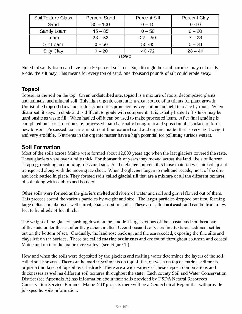
Soils are seldom composed of a single texture. Most soils are a mixture of the three and therefore will erode and settle differently. For example, Table 1 shows the five of the twelve different U.S Department of Agriculture (USDA) soil texture classes based on their percentage of sand, silt and clay.
Sec-I:5
Table 1
Note that sandy loam can have up to 50 percent silt in it. So, although the sand particles may not easily erode, the silt may. This means for every ton of sand, one thousand pounds of silt could erode away.
Topsoil Topsoil is the soil on the top. On an undisturbed site, topsoil is a mixture of roots, decomposed plants and animals, and mineral soil. This high organic content is a great source of nutrients for plant growth. Undisturbed topsoil does not erode because it is protected by vegetation and held in place by roots. When disturbed, it stays in clods and is difficult to grade with equipment. It is usually hauled off site or may be used onsite as waste fill. When hauled off it can be used to make processed loam. After final grading is completed on a construction site, processed loam is usually brought in and spread on the surface to form new topsoil. Processed loam is a mixture of fine-textured sand and organic matter that is very light weight and very erodible. Nutrients in the organic matter have a high potential for polluting surface waters.
Soil FormationMost of the soils across Maine were formed about 12,000 years ago when the last glaciers covered the state. These glaciers were over a mile thick. For thousands of years they moved across the land like a bulldozer scraping, crushing, and mixing rocks and soil. As the glaciers moved, this loose material was picked up and transported along with the moving ice sheet. When the glaciers began to melt and recede, most of the dirt and rock settled in place. They formed soils called glacial till that are a mixture of all the different textures of soil along with cobbles and boulders.
Other soils were formed as the glaciers melted and rivers of water and soil and gravel flowed out of them. This process sorted the various particles by weight and size. The larger particles dropped out first, forming large deltas and plains of well sorted, coarse-texture soils. These are called outwash and can be from a few feet to hundreds of feet thick.
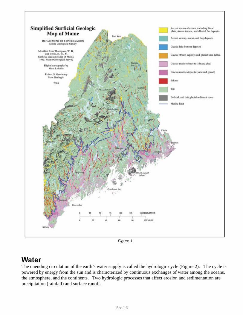
The weight of the glaciers pushing down on the land left large sections of the coastal and southern part of the state under the sea after the glaciers melted. Over thousands of years fine-textured sediment settled out on the bottom of sea. Gradually, the land rose back up, and the sea receded, exposing the fine silts and clays left on the surface. These are called marine sediments and are found throughout southern and coastal Maine and up into the major river valleys (see Figure 1.)
How and when the soils were deposited by the glaciers and melting water determines the layers of the soil, called soil horizons. There can be marine sediments on top of tills, outwash on top of marine sediments, or just a thin layer of topsoil over bedrock. There are a wide variety of these deposit combinations and thicknesses as well as different soil textures throughout the state. Each county Soil and Water Conservation District (see Appendix A) has information about their soils provided by USDA Natural Resources Conservation Service. For most MaineDOT projects there will be a Geotechnical Report that will provide job specific soils information.
Soil Texture Class Percent Sand Percent Silt Percent ClaySand 85 – 100 0 – 15 0 -10
Sandy Loam 45 – 85 0 – 50 0 – 20Loam 23 – 53 27 – 50 7 – 28
Silt Loam 0 – 50 50 -85 0 – 28Silty Clay 0 – 20 40 -72 28 – 40
Sec-I:6
Figure 1
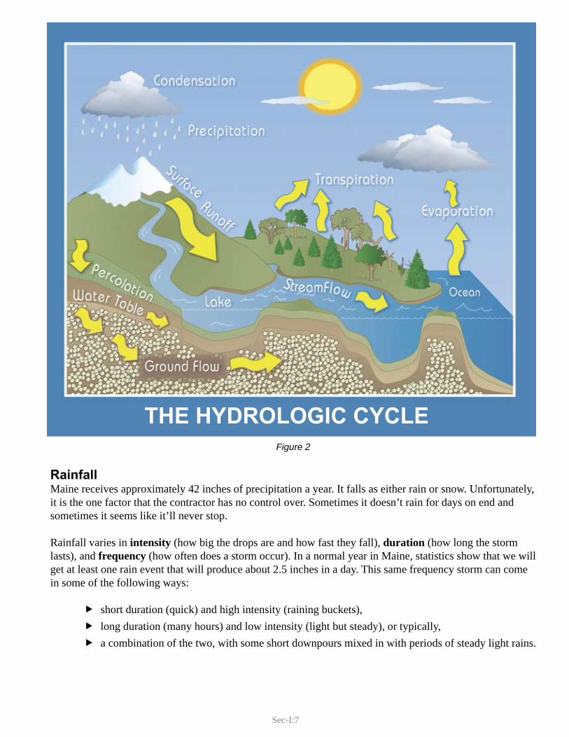
Water The unending circulation of the earth’s water supply is called the hydrologic cycle (Figure 2). The cycle is powered by energy from the sun and is characterized by continuous exchanges of water among the oceans, the atmosphere, and the continents. Two hydrologic processes that affect erosion and sedimentation are precipitation (rainfall) and surface runoff.
Sec-I:7
Figure 2
RainfallMaine receives approximately 42 inches of precipitation a year. It falls as either rain or snow. Unfortunately, it is the one factor that the contractor has no control over. Sometimes it doesn’t rain for days on end and sometimes it seems like it’ll never stop.
Rainfall varies in intensity (how big the drops are and how fast they fall), duration (how long the storm lasts), and frequency (how often does a storm occur). In a normal year in Maine, statistics show that we will get at least one rain event that will produce about 2.5 inches in a day. This same frequency storm can come in some of the following ways:
short duration (quick) and high intensity (raining buckets), flong duration (many hours) and low intensity (light but steady), or typically, fa combination of the two, with some short downpours mixed in with periods of steady light rains. f
THE HYDROLOGIC CYCLE

Sec-I:8
As you will see in the next section, all three of these storms may produce the same volume of rain, but they will produce different amounts of runoff. In general, high intensity downpours generate more runoff than low intensity light rain.
Runoff Factors Runoff is the surface water that flows over the land, through and off a construction site. It begins when rainfall has no place else to go - when soil and vegetation can no longer absorb and store rainwater it ponds on the ground, and if there is any slope to the land, runoff begins.
How runoff occurs on a job site depends on five factors:
Soil type fSurface cover and roughness fWatershed size fSlope of land fLength of slope f
Soil Type We have already discussed soil texture and permeability - sands are pervious (well-drained), silts are moderately pervious, and clays are impervious. Permeability has a great bearing on how much runoff is produced by a rainfall event. The movement of water into the soil is called infiltration and a common way of measuring permeability – the movement of water through the soil is called percolation. If, during a storm event the rainfall intensity is less than or equal to the infiltration rate and percolation rate, there will be no runoff - all the rain infiltrates and percolates through the soil. If however, the rainfall intensity exceeds the infiltration and percolation rates, the rain will pond on the surface and begin to run off. Sand has a high permeability rate because it is composed of large particles that pass water easily between the particles. Clays have essentially no permeability because the soil particles are flat, “plate-like.” It is very difficult for water to move through them. Silts are a mixture of the two, but because of the small particle size they react more like clays than sands. Organic matter greatly increases the permeability of soils because it allows water to run into and through the soil along root paths.
On bare soil intense rainfall can decrease the infiltration rate by physically beating the soil surface and compacting the soil particles. After an intense rain, this can be seen as a crust on the surface. Compaction by equipment also affects the infiltration rate. The more compacted the soil surface is, the lower the infiltration rate. The soil may have a high percolation rate, but it won’t matter if the water can’t get into the soil.
The depth of soil and height of water table will also influence when runoff occurs. Shallow soils and high water tables limit the volume of water that the soil can store. If the soil is already saturated, even if the water could get in it has no place to go and all additional rainfall will produce runoff. That is one reason why flooding occurs in the spring or after many days of rain.
Surface Cover and RoughnessSurface cover intercepts rainfall and protects the soil’s infiltration rate by preventing compaction of the soil. In most instances it is vegetation that is always preferred for soil stabilization, but as you will see in this manual other materials can be used. To simplify the explanation in this section we will only discuss vegetation.
Sec-I:9
Vegetation intercepts the impact of a raindrop. The leaves, stems, and branches of vegetation capture and hold raindrops. Roots of the plants loosen the soil, creating more pore spaces, increasing the infiltration rate, and increasing the storage capacity of the soil. All these characteristics will reduce the amount of runoff. The roughness of the natural ground surface produces many small pockets where rainfall can pond providing storage on the surface and giving the rainfall more time to either infiltrate or evaporate. This roughness can also be accomplished by grading.
When runoff does begin, the amount of vegetation and the roughness of the ground will effect how fast the runoff flows. The same amount of runoff flowing over bare, smooth ground will flow faster and shallower than water flowing through vegetated, rough soil.
Watershed A watershed is the area (acres or square feet) that captures rainfall and, once runoff begins, directs it to a common point of concern. For example, the watershed of your roof gutter is the area of roof that drains to it. The rainwater that falls on the other side of the roof is in a separate watershed. But if both downspouts flow into the same driveway ditch then they form a larger watershed consisting of your whole roof and any other structures or land that drains into that ditch. If the driveway ditch empties into a road ditch, then the watershed for the road ditch includes your home and property as well as all the other properties that are uphill from that point. Each time small watersheds combine the watershed becomes larger and the volumes of runoff water increase.
On construction sites the watershed may be the area above a cross-culvert or it may be a point where the contractor wants to install a particular BMP. Because construction typically involves removal of the vegetation and compaction of soils, even small watersheds can generate a large amount of runoff.
SlopeAny child with a toboggan understands how steepness of a slope affects speed. The same can be said for runoff; the steeper the slope, the faster the runoff flows.
Length of SlopeAs the slope length increases, the size of the watershed above the base of the slope increases, therefore so does the amount of runoff.
Types of RunoffAt the top of the watershed, runoff will usually begin to flow as a broad shallow film over the surface. This is called sheet flow. Sheet flow usually occurs for only fifty to one hundred feet before it concentrates. As it begins to gain speed and increase in depth it will begin to form small channels; this is called concentrated flow. There are two types of concentrated flow: shallow concentrated flow and channelized flow. Shallow concentrated flow forms small channels of water, from several inches to a foot in width. As these small rills of water come together, they form streams and eventually rivers; this is channelized flow. In the forest it may be difficult to see shallow concentrated flow (rills) because the ground is rough and the small rills may dry up after the rain. Streams and rivers are permanent channels that have actually eroded into the soil over many years. The size and slope of the watershed, and the permeability and depth of the soil will determine if the streams will flow year round or just intermittently. If the watershed stays undisturbed, the amount of runoff from the watershed stays relatively constant and these stream channels will change very slowly over time. But on construction sites there are changes to the landforms, slopes, slope lengths and the vegetative cover. Construction changes flow paths. Controlling the factors that effect runoff is the key to good water management and good erosion and sedimentation control. It is all about controlling the power of water.
Sec-I:10
The Power of WaterA falling raindrop, sheet flow, and concentrated flow all have energy. That energy working over a period of time can be very powerful. The power of falling and flowing water increases with an increase in the velocity and weight of water.
Consider standing in a shallow stream. The flowing water pushes against you, but because the depth is shallow you are able to stand up. Now imagine what would happen if the water was moving at the same speed but was as deep as your shoulders. The weight (depth) of water would increase the power and push you downstream. What if the water was up to your shoulders but not moving? As in the shallow stream you would not move. Velocity and weight create power, but velocity has a much greater impact on the amount of power produced than the weight. It doesn’t take much change in velocity to produce a lot more power. These same principles that apply to you standing in a stream, affect a soil particle and cause erosion and sedimentation.
For a given volume of runoff, the depth of runoff is determined by the velocity. The slower water flows, the deeper the depth; the faster water flows, the shallower the depth. Once runoff begins, the power of the runoff increases as the depth (volume) and velocity increase. This will occur until they reach a maximum amount for a given storm. Whether runoff flows as sheet flow or channel flow, the speed of the flow will be dependent on the slope and the surface cover or roughness that it is flowing over. The thicker the vegetation or rougher the rock lining, and flatter the slope - the slower it flows. When water, regardless of its depth, stops moving then sediment suspended in the water will begin to settle to the bottom, with the heavier particles settling faster than lighter particles. This same idea of power applies to rainfall. The power of a raindrop depends on its size and the speed that it falls. As we discussed earlier, this is the intensity. As the intensity increases so does the power. Controlling the power of water as it flows over soil is the basis for the majority of E&S control BMPs.
To complete this discussion of power, we must not forget wind. Wind is just air and has very little weight, but it certainly can have the velocity and that is what generates power.
Sec-I:11
2. THE EROSION PROCESSWe began this discussion on page 3 with a definition of erosion as the detachment and movement of soil particles by wind or water. In our discussion of soils, runoff, and the power of water and wind we presented the factors involved in the erosion process. Understanding this process is critical to determining how to control it. There are five different types of erosion that we are concerned about - four of them are forms of erosion by water, and one of them is by wind. They are raindrop erosion, sheet erosion, rill erosion, gully erosion, and wind erosion.
Raindrop ErosionRaindrop erosion occurs when rain drops collide with bare soil. The force of this impact dislodges soil particles and splashes them into the air. How much this occurs depends on the intensity of the rain (velocity and size of drops) and the texture of the soil (how much sand, silt, or clay). The harder the rain and the finer the soil texture, the more raindrop erosion will occur. Consider that a large raindrop will fall at a rate of 30 feet/second and may be up to 250 times larger than a silt particle. That silt particle doesn’t have a chance! Sand on the other-hand may be the same or up to twice the size of that raindrop and therefore has a better chance of absorbing raindrop impact and staying in place.
As soon as water begins to pond on the ground surface, runoff begins. But it isn’t just water. All of the soil particles that have been dislodged by the raindrops are now suspended in the water. If the land has even the slightest slope, the fine-textured soils will stay in suspension and begin to move with the runoff. At this point the second type of erosion occurs - Sheet Erosion.
Sheet ErosionSheet erosion occurs on unprotected soil when sheet flow runoff begins. The depth of water during sheet runoff is typically no more than ¼ of an inch, but that can be six to six thousand times deeper than the soil particles it is flowing over – and depth and velocity is power. This relative tidal wave of water easily picks up soil particles and carries them away. How fast and far this sheet of water flows depends on the surface cover and roughness, and the slope of the land.
Sheet erosion usually moves the GREATEST AMOUNT of soil from an unprotected job site. For instance, the loss of just 1/8 of an inch of soil off one acre of land will fill a 10 wheel dump truck (15 cu.yds. or 25 tons). On steep, unvegetated highway backslopes sheet erosion may only occur for twenty feet before it develops into the next form of erosion - Rill Erosion.
Rill Erosion Rill erosion occurs when the sheet erosion gains enough power (velocity and depth) to concentrate and cut very small channels into the soil. As more water flows into these small channels, the water depth and power increases and they cut deeper into the soil. These small channels are called rills. They are no more than an inch wide and one to two inches deep.
Keep in mind that between these rills, raindrop and sheet erosion is still occurring. This water will also flow down the slope parallel to the rills, combine with the rills and form the most destructive form of erosion - Gully Erosion.
Gully Erosion Gully erosion occurs when water is concentrated and flows with enough power (velocity and depth) to cut into the soil to a depth of over one foot. It will occur as a result of rills coming together on an unprotected
Sec-I:12
slope. On road projects, gullies form near the base of long slopes, in the bottom of an unprotected ditch, or as water flows off of a road surface, parking lot or other flat grade onto a steep unprotected slope.
Interestingly, gullies form from the bottom of the slope and progress uphill. The flowing water reaches a critical level that a small waterfall forms and the power of the water falling over the edge (increased velocity) erodes the soil at that point and this erosion proceeds upstream. This small waterfall that moves upstream is called a head cut and leaves steep banks downstream. The steep banks will begin to collapse under their own weight, that soil will also wash away, and the gully widens further.
Gullies can form anywhere the power of water is strong enough to begin to scour the soil and begin this head cutting process. If left untreated, the head cut will continue to move up the slope until the watershed decreases in size, which decreases the volume of runoff, which decreases the depth of water, which decreases the power enough that the soil can resist it and not erode. At the lower reaches of the gully it will continue to cut down and widen out to the point that the slope may actually flatten out, slow the velocity and decrease power enough that the erosion rate may slow down enough for sedimentation to occur in the gully.
It was stated above that sheet erosion erodes the greatest amount of soil because it covers a larger area, but gully erosion is the most dramatic. Which ‘costs’ the most? Gully erosion is the most expensive for the developer or contractor to repair but sheet erosion usually costs our water resources the most.
On transportation projects, the length of back slopes and size of watersheds are usually small enough that gullies do not form as described above. But they do form in constructed channels (ditches) or where water flowing off the road surface is concentrated on the shoulder by a grader berm, constructed curb, or a winter sand berm then allowed to spill onto an unprotected inslope.
In reading this section about water erosion you can see that the types of erosion are determined by the types of runoff.
Wind Erosion Wind erosion occurs when the wind dislodges, picks up, and transports the soils. As with water, the texture of the soil moved depends on the power of the eroding force. Wind can cause dust clouds or sand storms. It occurs when the soil is dry, loses or has no cohesion, and is unprotected from the power of the wind. Dust is a major form of non-point source pollution.
3. EROSION CONTROLControlling erosion is all about decreasing the power of the water or wind, and protecting the soil from it. The power is decreased by applying best management practices that influence the soil, surface cover, watershed size, slope, or slope length; or that decrease the volume or velocity of runoff. Decreasing the power is not always possible to do, but protecting the soil from the power of water and wind by covering it can always be done. Providing protection by applying mulch or other protections is usually the most practical method of preventing erosion.
The type of erosion control BMPs used are determined by the type of erosion that is occurring. The basic principles apply: protect the soil and/or reduce the power (velocity and depth) of the flowing water. To control wind erosion, controlling the velocity of the wind is done by using wind breaks and adsorbing or deflecting the power. This is not always practical, but we are able to protect the soil from the power of the wind in the same way as with the water – by covering it.
Sec-I:13
The erosion control BMPs in this manual are presented in three sections based on the type of runoff that generates it. Raindrop, sheet, and rill erosion occur over a broad area and will be called Sheet and Rill erosion. Gully erosion in channels will be called Concentrated Flow. Wind erosion is addressed as dust control in the Miscellaneous section.
4. THE SEDIMENTATION PROCESSSedimentation is the deposition of soil particles that have been eroded. Soil particles are deposited when the power (velocity and depth) of the water or wind that is carrying them is no longer strong enough to keep them suspended. Sediments are these soil particles once they settle out.
Sedimentation control is typically achieved by ponding water to slow it down. Stopping the water entirely and letting it infiltrate or evaporate would be ideal, but on construction sites that usually is not possible. Because soil particles have to have enough time to settle, it is critical to slow the velocity of the water as much as possible, have the ponded area basin be as shallow as possible, and have the distance the water flows through the basin as long as possible. The time it takes for a particle of soil to settle through the ponded water and settle on the bottom is called the residence time. The longer the residence time, the better. If the water speeds up again before the soil particles settle they will be re-suspended.
The size and shape of the particle has a great effect on the rate of sedimentation. Coarse texture soil particles (sand) will settle easily. They are heavy and blocky in shape. Clays are extremely small and are plate-like in shape. It is almost impossible to settle out clays, they float like feathers in the wind. Silts are not much better, they may be blocky in shape but they are very small in size. Because settling out silts and clays is so difficult, most sedimentation BMPs do not capture these particles well. Table 1 shows that a typical loam will have no more than 53% sand. If this soil erodes from a site almost half of it (silts and clays) will be very difficult, if not impossible, to settle out before leaving the site. There are methods to remove fine texture soils but they require expensive treatment methods and filtering. Therefore, it is much easier and less expensive to prevent erosion in the first place.
The key factors in the sedimentation process are the soil texture (particle size), the speed and depth of the water, and the distance the water flows through the BMP.
Filtration of sediment laden water through vegetation, pervious soils, or commercial structures is an alternative to settling in a ponded area.
5. SEDIMENTATION CONTROLThe type of sedimentation BMP used is governed by the type of runoff and erosion that is occurring. Sheet and Rill erosion have shallower depth, slower velocities, and occur over a broader area. The best sedimentation BMPs for this type of erosion are BMPs that are placed on the contour of the land and provide ponding at shallow depths, promote infiltration of the water (leaving the sediment on the surface), or provide filtration of the water.
Sediment laden water in concentrated flow may be from gully erosion or may have come from sheet and rill erosion that has been carried into a Concentrated Flow channel. This water is usually deep, fast, in a confined space, and over the duration of a rain event, involves a large volume of water. There are three approaches to removing sediment from concentrated flow: provide slow flow through a basin with a long residence time allowing soil to settle; convert concentrated flow back into sheet flow and utilize those sedimentation control BMPs; or use an engineered commercial devise to remove sediment through mechanical means.
Sec-I:14
The sedimentation control BMPs in this manual are presented in two sections based on the type of erosion that is occurring: sedimentation control BMPs for Sheet and Rill erosion and sedimentation control BMPs for Concentrated Flow erosion.
6. RuleS of ThumbBefore leaving this section, here are some general rules and observations about erosion and sedimentation:
Erosion always happens before sedimentation. You can have erosion without sedimentation but fyou cannot have sedimentation without erosion. Erosion control is keeping the soil out of the water. Sedimentation control is removing the soil ffrom the water. It is easier to keep it out than to remove it.Erosion control is protecting the soil from the power of water – the impact of the raindrop, and the fvelocity and depth of runoff and concentrated flow. Whenever possible you should:
decrease the amount of water on the project site by dividing watersheds and increasing yinfiltration,slow the water down by flattening grades or roughening surfaces that the water flows over, yandcover the soil with something that can withstand the power of water. y
Sedimentation control is slowing the water velocity enough and for a long enough time for the soil fto settle out. How much settles depends on soil texture.Construction being what it is, you can not always protect the soil from erosion; and sedimentation fcontrol is your safety net. Sedimentation control is the last line of defense but should be the first BMPs installed.
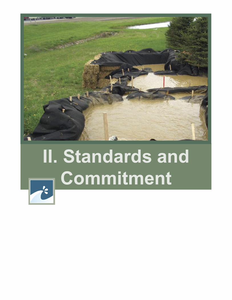
II. Standards andCommitment

Sec-II:1
A. TEMPORARY SOIL EROSION AND WATER POLLUTION CONTROL Erosion and sedimentation control is the use of practices and procedures to minimize erosion and to settle out sediment before surface water leaves the job site. Incorporating these practices and procedures into a construction project requires proper planning, and knowledge and experience to develop and apply erosion and sedimentation controls (ESC).
1. THE ESC PLANAn ESC plan may have different names: at the Maine Department of Environmental Protection (DEP) it is a Storm Water Pollution Prevention Plan (SWPPP) while at MaineDOT it is a Soil Erosion and Water Pollution Control Plan (SEWPCP). The name may change, but it serves the same purpose – documenting what practices and management procedures will be used to prevent a discharge of sediment and pollutants. When they apply, state and federal regulations require assurance that the proper BMPs will be installed in the right sequence and maintained for their intended use – they require a written plan. But the real value of the plan is for the contractor to think through the process of integrating BMPs into the construction project. It is essential that the person writing the SEWPCP understand the construction process and the basic principles of ESC and how the BMPs function. The complexity of a SEWPCP depends on the size and complexity of the project, the amount of exposed soil, the proximity of the project to a water body, and the sensitivity of the waterbody. If the project is completed in a single day, the plan may be to seed and mulch all disturbed areas and inspect and maintain the site until the grass grows; it may not even require sedimentation control. If the project is large, complex, and extends over multiple construction seasons then sequencing of construction and BMP installation with the phases of the project may be complicated, and inspection and maintenance will require more time and effort. Depending on weather or changes in project scope, the plan may require revision, but the process is the same and a good planner has the knowledge, experience, and tools to do the job well.
2. SIX PRINCIPLES OF EROSION AND SEDIMENTATION CONTROLWhen developing a SEWPCP for a construction project, the following six principles will help guide you in developing and implementing the plan. All six general principles apply to all earthmoving construction sites, but all sub-categories may not.
a. Know the Watershed
i. Know where the project is located in the watershed and how much of the watershed is above the siteBefore choosing BMPs, look for signs of concentrated flow (either storm water or spring runoff). If they exist, look at the watershed above the backslopes, private driveways that concentrate flow to road ditches, and length of ditches and off site watersheds that flow to them. Are there indications of seeps and continuous flow?

Sec-II:2
ii. Know the soils and materials that you are working with Are they highly erodible? Do they drain well? Are you dealing with steep slopes on which it may be difficult to establish vegetation?
iii. Land use, location, and time of yearLook at the land use cover. In general, wooded areas will produce runoff slowly but for a longer time. Urban areas will quickly produce larger amounts of runoff for a given rainfall. Anticipating flow rates is critical to good water management.
Consider how much sun the project site gets. If you are on the north side of a slope, soils may not dry out and grass grows slowly. If you are in an open area exposed to the sun and wind, the soil may dry out too quickly, grass may need to be watered, and dust control will be a concern.
The time of year has similar effects on soil moisture and establishment of vegetation. Also consider that summer thunderstorms are quick-hitting and intense while fall and spring rains tend to be less intense but last longer.
iv. Know where the water goes when it leaves the site and what the water resources are If not identified in the plans, assume that any stream, lake, pond, or wetland should be avoided and protected before any earthmoving occurs. When in doubt, ask. Always walk or drive the site, use a map if necessary, and identify where the water goes and how far away your project is from the water resources. More importantly, how does it get there? If it is sheet flow through a buffer there is an opportunity for treatment; if it is concentrated flow, there is not.
b. Construction Timing and Phasing
i. Minimize clearingKeep disturbed areas small. Only open up what you can manage. The smaller the bare soil area exposed to rainfall and runoff, the less erosion there will be. Minimize soil disturbance during clearing and delay or stage the grubbing operation wherever possible.
Avoid clearing steep and long slopes. It always depends on the site but slopes greater than 3:1 and longer than 50 feet are areas where you should be cautious.
ii. Build from the bottom up On projects where the excavation is used to build the fills, plan and stage the work such that the bare soil area is kept to a minimum.
For all concentrated flow channels (ditches), stabilize the outlet first and build from the bottom up. Only excavate what can be stabilized or protected by the end of the work day. All cross culvert outlets should be armored before the end of the work day.
iii. Winter stabilizationTime of year is critical for stabilization. Spring thaws and rain events are the most erosive times of the year. Surface soils are usually saturated and have little strength, and vegetation is laid down or dead providing less protection from rainfall and runoff. If construction will extend into late fall or later, consider the need for appropriate erosion and sedimentation controls will be in place and functioning as the snow melts the following year.
Sec-II:3
iv. In-water workFishery agencies usually require that work within a stream, or other water body only occur during certain months of the year, typically mid July through September. Scheduling operations within those months requires coordination and planning.
c. Control the Water
i. Divert, disperse, detainThe key to E&S control is to keep the depth (volume) and velocity of water as low as possible. Whenever possible:
Divert clean water away from the exposed soil. Use temporary ditches, hillside diversions, and downspouts to carry water from the uphill watershed away from exposed soil. This may be around or through the site. Be sure that constructed channels are stable before they receive runoff. Because it takes time for vegetative channels to stabilize, this will usually require using riprap or plastic sheeting to divert the water.
Disperse the flows. Where practicable keep runoff water in sheet flow and treat smaller areas with sedimentation control BMPs such as Erosion Control Mix Berms and Silt Fence. Smaller quantities of water in sheet flow are easier to handle than concentrated flow.
Detain dirty water. Whether in sheet flow or concentrated flow, detaining the water – slowing it down – removes sediment. Use appropriate sedimentation control BMPS.
ii. New permanent channelsBefore permitting permanent channels to carry water they shall be stabilized. This may require the installation of temporary erosion control BMPs or temporarily diverting flows.
iii. While gradingOn projects with slopes that will not have final cover for periods longer than a week, in addition to mulch, consider using land grading BMPs to slow down the runoff. Even at the end of each day all pockets and diversions created with a pass of a bulldozer blade or excavator bucket can help other BMPs to detain and slow the water down.
d. Soil Stabilization
i. Temporary stabilizationMulch is the most effective BMP! Stop erosion before it starts! Most sites should have temporary mulch applied at the end of each work day.
Mulch will protect the soil from raindrop impact and promote infiltration of runoff into the soil. This will decrease the volume of water that runs off the site. Mulch will also slow down sheet runoff. Refer to the mulch BMPs for various types of covers.
Remember slope and slope length are critical to when sheet erosion turns into rill erosion, and then gully erosion. Consider using grading techniques in combination with mulches to limit slope length.
Sec-II:4
ii. Permanent stabilizationPlace final treatments as soon as possible after final grading.
Install permanent erosion control BMPs, such as riprap downspouts, or stone ditch protection, as part of the slope or ditch construction.
e. Keep Sediment On-Site
i. last line of defense/first bmPSedimentation control is the last line of defense in keeping sediment out of water resources, but it should be the first BMP installed as insurance against not having 100% erosion control. It provides a final treatment of all runoff.
f. Management
i. Assign responsibilityAs with any job that needs to be done, there must be someone in charge. For E&S control that person needs to be an employee of the Prime Contractor that has the authority to ensure that the SEWPCP is followed and practices maintained.
ii. Inspect and maintain As with equipment maintenance, E&S control maintenance requires inspection and, if needed, correction at least once a week and before, during, and after storm events. E&S control is a daily activity on an earthmoving construction project, so treating E&S control as a daily activity like fueling and lubing equipment will prevent unexpected problems.
iii. Follow-up; remove temporary sediment control barriersTemporary measures such as temporary check dams, sediment barriers, temporary slope drains, etc. must be removed when disturbed areas have been permanently stabilized. If left on-site, temporary measures may actually cause erosion and be an eyesore for years. Erosion Control Mix filter berms may not have to be removed. In most circumstances they can be spread out, seeded and left to decompose. However silt fence and hay bale barriers must be removed from the site. Areas disturbed during the removal of these devices must be properly stabilized.
3. SPILL PREVENTIONAlthough spill prevention is not specifically covered in this manual it is a water quality issue that must be addressed during construction. Leaks from hydraulic hoses or fuel spills and leaks can have great impacts on surface and ground water resources. To minimize the environmental impacts associated with unplanned releases, it is important to ensure that “good housekeeping” practices are followed and that prompt actions are taken to respond to spills or leaks. Unto that end, the contractor shall use proper fuel filling procedures, maintain equipment to prevent leaks, have “spill kits” on the job site to clean up spills if they occur and develop a project specific plan for responding to releases. Most importantly, they should know who to call if there is a spill and the proper procedures for reporting and clean-up.
Sec-II:5
4. MAINEDOT PROCEDURES
a. Project DevelopmentMost regulated construction projects are required to have an ESC plan written before a permit is issued and construction begins. These plans are usually written by the design team well before construction begins. The disadvantage of this process is there are usually unanticipated site conditions, weather, or contractor resources that require modification to the plan. The MaineDOT through an agreement with the Maine DEP (see Stormwater Memorandum of Agreement) have resolved this issue by having the contractor who is doing the work write and implement the SEWPCP. It is a contract specification and bid item: Standard Specification 656 – Temporary Soil Erosion and Water Pollution Control (see Appendix C) that provides the requirements for the contractor to incorporate into their SEWPCP. The advantage of this method is that the contractor takes ownership of the SEWPCP. They are responsible for developing the construction schedule for the project, and the SEWPCP becomes part of that process. The MaineDOT approves the SEWPCP before any work begins, oversees its implementation, and has the authority to assure full compliance. The Surface Water Quality Unit (SWQU) of the Environmental Office at MaineDOT maintains this specification and this manual, and assists Project Development in compliance of this.
b. Maintenance and OperationsWhen construction projects are undertaken by MaineDOT Maintenance and Operations (M&O) crews, the crew foreman or superintendent write the SEWPCP in the same manner as the contractor, describing how the proper BMPs are incorporated into the project and how they are inspected and maintained. Internal policies and procedures are in place to assure the SEWPCP is implemented. The SWQU assists the Region Environmental Coordinators in overseeing this program and provides training to all field crews on a biennial basis.
5. SEWPCP CONTENTThe SEWPCP is not only for the benefit of the contractor to address erosion and sedimentation control, it is also a permit requirement and part of the construction contract with MaineDOT. Because the MaineDOT reviews and approves the SEWPCP before any work begins on a project, we look for specific items in our reviews. The following are items that, when they apply to the project, should be addressed in a SEWPCP:
a. name of the person preparing the SEWPCP;
b. name of the on-site person responsible for implementation of the plan with phone numbers or pager numbers that can be used to contact the person in case of emergency;
c. the schedule and sequence of all activities involving soil disturbance;
d. emergency storm response procedures including a list of materials which will be kept on-site to handle emergencies, and procedures for corrective action in case of BMP failure;
e. a narrative of how the SEWPCP meets or exceeds the requirements of Section II of the BMP manual;
f. type and location of all temporary erosion and sedimentation control measures, including temporary measures for winter stabilization between November 1st to April 1st;
g. mulching type, thickness of mulch, and frequency of application for disturbed earth areas;

Sec-II:6
h. location and frequency of temporary seeding;
i. dust control procedures for staging areas, stockpile areas, haul roads, and any other areas;
j. location and method of temporary sedimentation control at inlets and outlets of existing and proposed catch basins and at outlet areas;
k. description of all in-water work, including the timing of work, temporary stream diversions and the types, location, and size of cofferdams;
l. description of the design and location of any sedimentation basins for dewatering the cofferdams, including alternative plans when the sedimentation basin overflows;
m. inspection and maintenance schedules for all erosion and sedimentation control measures, temporary and permanent, including the method, frequency, and disposal location of sediment removed, and maintenance of temporary winter stabilization BMPs;
n. procedures and schedule for removal of all temporary erosion and sedimentation control measures;
o. a Spill Prevention Control and Countermeasure Plan (SPCCP).
Sec-II:7
B. POST CONSTRUCTION STORMWATER MANAGEMENT AND COMPLIANCEIn the first publication of this manual, the MaineDOT and Maine Turnpike Authority (MTA) committed to implementing basic permanent stormwater practices to control long term impacts. These practices focused on long term erosion control and permanent stabilization of areas that are subject to concentrated flows such as waterways, downspouts, and culvert inlets and outlets. These permanent stormwater practices are incorporated as design standards for all projects.
Erosion and sedimentation from disturbed soils on construction sites is not the only type of non-point source pollution that is associated with transportation projects. Impervious surfaces of roads, bridges, and parking areas can also be a source of non-point source pollution. Runoff from these surfaces may carry nutrients, salt, heavy metals, and petroleum products to the water resources. Research has shown that the quantity of pollutants from road systems is directly related to the Average Annual Daily Traffic (AADT). There needs to be approximately 30,000 cars per day traveling over a road section before there is a significant pollutant load. Parking lots have a higher potential but that too depends on the number of vehicles that use them. Melt water from winter snow piles have also shown high levels of chlorides from winter salt application.
Impervious areas also increase the rate of runoff and decrease infiltration rates to the groundwater table. These changes in the hydrologic cycle can disrupt stream channels causing bank and bed erosion, increased water temperatures, and decreased groundwater discharge to streams during periods of little rain.
Controlling stormwater quantity can be difficult on transportation systems. Roads are impervious and for safety concerns water must be removed from the surface as quickly as possible. Right-of-way constraints require ditches to be constructed parallel to the road, limiting the available area for BMP installation. Also, road drainage systems are connected to commercial and residential development off site and may carry pollutants from these areas.
Permanent stormwater BMPs for post construction runoff are available, but they are still being developed for transportation systems. The MaineDOT has begun gathering information to publish a design manual for permanent stormwater BMPs for transportation systems. In the interim, the Surface Water Quality Unit will provide guidance to designers in evaluating the feasibility and the design of these BMPs.
In recent years state and Federal regulations have been enacted to require treatment of post construction runoff. The next section will describe how the MaineDOT addresses these requirements.

Sec-II:9
C. REGULATORY COMPLIANCE FOR MAINEDOT AND MTAState and federal regulations require the MaineDOT and MTA to address both stormwater quality and quantity during the construction process and for post construction runoff. These regulations vary and are increasing in number and complexity. This section describes the standards and procedures for compliance by the MaineDOT and MTA with applicable stormwater regulations administered by the DEP.
1. STORMWATER MANAGEMENT LAWThe standards for compliance with the Stormwater Management Law are documented in the DEP Chapter 500 Stormwater Management Rules. These rules are triggered by the extent of disturbed area, and have conditions for Lakes Most at Risk and Urban Impaired Stream watersheds.
a. Memorandum of AgreementIn 1998 MaineDOT, the MTA, and the DEP signed a Memorandum of Agreement (MOA) to address how state transportation system projects would meet the DEP Chapter 500 Stormwater Management Rules.
Through the years this MOA has been revised in response to regulatory changes. On December 27, 2006, the state adopted major revisions to the Maine Stormwater Management Rules. The MOA and by reference this BMP manual have been revised to reflect both the regulatory changes and institutional knowledge gained through the application of best management practices over time.
In the MOA, DEP recognizes that state transportation projects collectively have the potential to disturb significant amounts of soil, but because the majority of these individual projects disturb less than one acre, they do not trigger compliance requirements of the current regulations.
The MaineDOT and MTA recognize that obtaining individual stormwater permits from DEP for projects meeting the DEP’s Stormwater Management Rules thresholds could adversely affect the schedule and budget for projects.
The MOA gives MaineDOT and MTA the oversight authority for projects that trigger the Stormwater Management Rules. In return, MaineDOT and MTA agree that all construction and maintenance projects that involve earthmoving (not just the projects that trigger Stormwater Management Rules) will have an ESC plan and procedures in place to insure that this plan is followed; and when the standards for permanent stormwater management are triggered the MaineDOT and MTA will, where practicable, install BMPs to mitigate stormwater impacts.
This agreement has been a success for all of the agencies involved. MDEP is assured that extensive E&S and stormwater controls occur on all projects and MaineDOT and MTA have more control over their own budget and schedule and the flexibility to use BMPs that best suit state transportation system projects. This agreement took a great deal of effort, negotiation, and trust to develop and demonstrates how agencies can work together toward a common goal.
The current MOA (Appendix B) states the specific provisions for complying with the standards of the Chapter 500 Stormwater Management Rule. The following details the commitments, procedures, and standards that the MaineDOT and the MTA will use to comply with the MOA.
Sec-II:10
b. Basic StandardAs stated in the MOA, ESC plans are prepared for all earthmoving construction projects undertaken by the MaineDOT and the MTA. MaineDOT has developed Standard Specification 656, Temporary Soil Erosion and Water Pollution Control, which requires the contractor to develop a Soil Erosion and Water Pollution Control Plan (SEWPCP), have it approved by MaineDOT, and implement it for the life of the contract. This standard has requirements for documenting inspections and maintenance as well as a Spill Prevention Control and Countermeasures Plan. Earthmoving construction and maintenance projects carried out by state employees are also required to develop and implement a SEWPCP. This manual is referenced and incorporated into that standard and provides guidance and specifications for BMP implementation. These requirements are administered by the Surface Water Quality Unit (SWQU) of MaineDOT’s Environmental Office.
MTA incorporates a modified version of the Standard Specification 656 in contract documents for all contracted projects involving earthwork or potential stormwater impacts to achieve the same goals as the MaineDOT process. These modifications are primarily related to MTA preferences relative to the bidding and payment processes. The equivalent of MaineDOT’s SEWPCP is prepared under the direction of a licensed professional engineer and included in the bid documents. Earthmoving construction and maintenance projects carried out by MTA employees are supervised by an MTA designee who has been certified through DEP’s Nonpoint Source Training and Resource Center or equivalent or are licensed professional engineers experienced in stormwater rule requirements.
The standards implemented by MaineDOT and MTA for temporary erosion and sedimentation control exceed the standards required in the Basic Standard in both extent of projects that apply and level of BMP implementation.
c. General Standard and Phosphorous StandardThe General Standard is triggered when a project exceeds specified thresholds for impervious and developed areas. This standard addresses the primary nonpoint source concerns in stream systems: channel protection, pollutant removal, runoff cooling, flood control, and groundwater recharge. This is of particular concern in urban impaired stream watersheds. One of the major changes to the Chapter 500 Stormwater Management Rule is the inclusion of standards for unnatural flow quantities related to channel erosion. Prolonged higher than normal flows (not necessarily larger peak flows) from urbanized watersheds result in excessive instream erosion and instability and decreased stream base flow because of the extent of impervious surface and engineered drainage systems. These factors also dramatically decrease natural infiltration and recharge related to the streams.
The Phosphorous Standard is triggered when the project is in the watershed of a Lake Most at Risk as identified in MDEP’s Chapter 502. This standard addresses water quality and pollutant loads carried by the runoff, in particular the phosphorous associated with sediment. Temperature is also a concern. Water quantity is not.
These two standards establish thresholds and permanent treatment standards for both water quality and water quantity impacts to the surface water resources of the state. They were written with traditional site development in mind: housing and commercial projects. Linear transportation systems differ from these traditional sites in that they typically cross many sub-watersheds with multiple points of discharge and the total increase in developed and impervious areas for a project are tempered.

Sec-II:11
Linear public transportation systems do not conform well with the performance standards in the appendices of the MDEP’s Chapter 500, Stormwater Management Rules. The extent and design of impervious areas are restrictive by federal standards and drainage patterns are limited by the extent of right-of-way. But nationwide, state transportation agencies and permanent best management practices for stormwater management are being developed utilizing the principles of low impact development, bio-retention, and filtration systems within the drainage right-of-way.
When linear projects trigger the thresholds for the General Standard or the Phosphorous Standard the MaineDOT and the MTA have agreed to evaluate runoff impacts and, where practicable, utilize existing practices and new technologies to treat highway runoff at levels comparable to those specified in these standards.
Except for redevelopment, non linear portions of projects that trigger the General Standard of the Chapter 500 Stormwater Management Rules shall comply with those requirements.
The MaineDOT has a representative of the Surface Water Quality Unit (SWQU) assigned to every construction project team providing the needed oversight and review of each project from design kickoff, through construction and closeout and the MTA equivalent is a licensed professional engineer experienced in stormwater applications. These team members will assess the project. When necessary they recommend the design and installation of permanent stormwater BMPs. An assessment of source, impact, and receiving waters is made with recommendations for needed permanent BMPs.
d. Urban Impaired Stream Standard and Flooding StandardProjects that are not associated with an existing travel corridor, and are located within the watershed of an urban impaired stream, and trigger the Urban Impaired Stream Standard shall meet the Urban Impaired Stream Standard in the Chapter 500 Stormwater Management Rules. Projects that trigger the thresholds of the Flooding Standard shall apply design and engineering measures to the extent practicable to avoid adverse impacts to offsite property.
e. MaintenanceThe MaineDOT has inventoried every permanent practice installed and has an annual inspection and maintenance schedule incorporated into the Maintenance and Operations Bureau to ensure long term viability of these practices.
2. MAINE CONSTRUCTION GENERAL PERMIT
a. StandardThe Maine Construction General Permit (MCGP) is a permit required under the National Pollutant Discharge Elimination System Phase II of the Clean Water Act. The DEP has delegated authority from the Environmental Protection Agency to administer it in the state of Maine. The project specific requirements for an ESC plan, housekeeping, and inspection and maintenance are almost identical to the requirements of the Chapter 500 Stormwater Management Rules, Basic Standard. As described in Section II.C.1.b. above the standards and procedures of the MaineDOT and the MTA will also exceed the standards of the MCGP.

Sec-II:12
b. SubmittalsThere is additional administrative documentation required by EPA. The following describes how the MaineDOT and the MTA will comply with those requirements.
Notice of Intent – The MaineDOT and the MTA will submit a single Notice of Intent (NOI) at the beginning of the construction season for all projects with all required data for each project tabulated in an attachment or retained on file and, if requested, available for project specific review.
All records will be retained for three years beyond the construction end date.
Notice of Termination – The MaineDOT and the MTA will submit a single Notice of Termination (NOT) at the end of the construction season for all projects with all required data for each project tabulated in an attachment.

Sec-II:13
D. GUIDANCE FOR SENSITIVE WATER BODIES
1. HISTORYSection IIB of the first edition of this manual required that “sensitive water bodies need to have additional erosion controls beyond the standard practices” and “the primary difference for a project in the watershed of one of these resources will be that the project must use a combi nation of BMPs to protect the resource, and one of the BMPs must be an erosion control BMP versus a sedimentation control BMP.” In addition, it required five other temporary erosion and sedimentation control issues be considered and that long term stormwater treatment and stabilization be provided.
A list of these sensitive waterbodies was compiled by MaineDOT and provided in the Appendix of the first edition of this manual. The Special Provision to the Standard Specification 656 Temporary Soil Erosion and Water Pollution Control would inform the contractor that a project was in a sensitive watershed and require them to follow Section IIB of the BMP Manual.
This list of sensitive waterbodies was more extensive than that required under DEP’s Chapter 500 Stormwater Management Rules and resulted in the vast majority of the MaineDOT projects falling within a sensitive watershed requiring this higher level of treatment. This level of treatment became the standard for contractors doing work for MaineDOT. For example, in addition to the installation of sedimentation control BMPs, daily mulching of disturbed areas is common. Therefore, designating certain waterbodies as “sensitive” became redundant.
2. STANDARDThe MaineDOT Surface Water Quality Unit (SWQU) has found that within this large group of projects in sensitive waterbody watersheds, there are those that, because of the combination of the sensitivity of the waterbody, scope of work, proximity of the project to the waterbody, the time of year, etc. do require an even higher level of treatment. That assessment is made by a representative from the SWQU in consultation with regulatory and resource agencies as well as other members of the project design team. These projects will now be called SENSITIVE PROJECTS.
The higher level of treatment will be reflected in project specific requirements included in the project contract via Special Provisions to the Standard Specification 656. The contractor will address those site specific requirements in their SEWPCP, which is approved by the MaineDOT and implemented by the contractor with assistance and oversight by the project Resident and the SWQU representative. In addition, a higher level of inspection and compliance assurance by MaineDOT is required.
Projects within the following watersheds are required to be designated as SENSITIVE PROJECTS:
Lakes Most at Risk Watersheds fUrban Impaired Streams fAtlantic salmon Distinct Population Segments f
As noted above, the SWQU may designate a project sensitive when other factors warrant it. For example, large projects with extensive land clearing, steep slopes or close proximity to waterbodies. In addition to a higher level of treatment during construction, permanent stormwater practices are incorporated into the design as needed.


III. Best Management Practices

Sec-III:1
A. HOW TO USE THIS MANUALThe BMPs in this manual are separated into sections focusing on the type of problem you are trying to address, making a distinction between the type of erosion occurring, i.e. sheet and rill vs. concentrated flow. It further distinguishes between erosion control practices and sedimentation control practices. This allows the writer of the SEWPCP to look at the site conditions and identify what conditions will be encountered during construction, and then go to the appropriate section of the manual to find specific BMPs to meet the needs of the project.
For other BMPs that are specific to the construction activity, see subsequent sections for In-Water Work and Miscellaneous.
This manual will also present some permanent BMPs that can be incorporated into the post construction stormwater management plan but does not give guidance in controlling post construction stormwater management.
Sheet and Rill – Erosion Control (SR-EC) fSheet and Rill – Sedimentation Control (SR-SC) fConcentrated Flow – Erosion Control (CF-EC) fConcentrated Flow – Sedimentation Control (CF-SC) fIn-Water Work (IN-WATER) fMiscellaneous (MISC) f

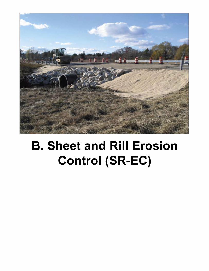
B. Sheet and Rill Erosion Control (SR-EC)

Sec-III:5
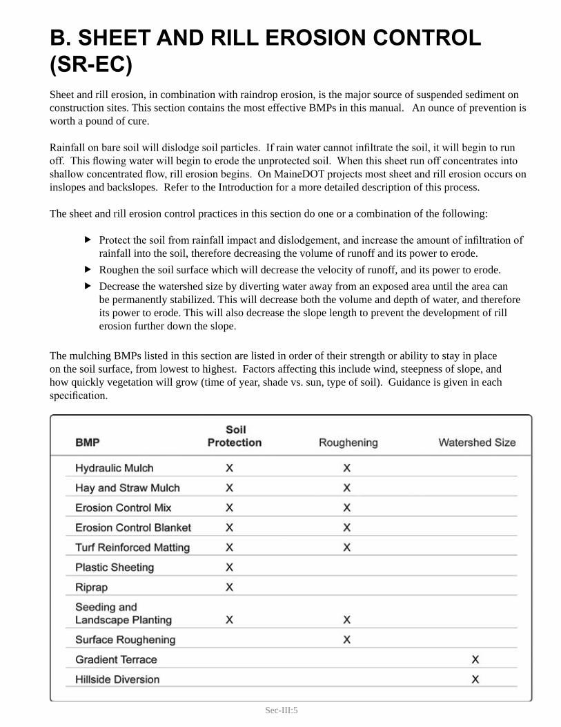
B. SHEET AND RILL EROSION CONTROL (SR-EC)Sheet and rill erosion, in combination with raindrop erosion, is the major source of suspended sediment on construction sites. This section contains the most effective BMPs in this manual. An ounce of prevention is worth a pound of cure.
Rainfall on bare soil will dislodge soil particles. If rain water cannot infiltrate the soil, it will begin to run off. This flowing water will begin to erode the unprotected soil. When this sheet run off concentrates into shallow concentrated flow, rill erosion begins. On MaineDOT projects most sheet and rill erosion occurs on inslopes and backslopes. Refer to the Introduction for a more detailed description of this process.
The sheet and rill erosion control practices in this section do one or a combination of the following:
Protect the soil from rainfall impact and dislodgement, and increase the amount of infiltration of frainfall into the soil, therefore decreasing the volume of runoff and its power to erode.Roughen the soil surface which will decrease the velocity of runoff, and its power to erode. fDecrease the watershed size by diverting water away from an exposed area until the area can fbe permanently stabilized. This will decrease both the volume and depth of water, and therefore its power to erode. This will also decrease the slope length to prevent the development of rill erosion further down the slope.
The mulching BMPs listed in this section are listed in order of their strength or ability to stay in place on the soil surface, from lowest to highest. Factors affecting this include wind, steepness of slope, and how quickly vegetation will grow (time of year, shade vs. sun, type of soil). Guidance is given in each specification.

Sec-III:7
1. HYDRAULIC MULCH
Definition and PurposeHydraulic mulch consists of a mixture of mulch and mulch binder that is sprayed onto unvegetated soil to protect it from raindrop erosion and, to a limited extent, the erosive forces of sheet flow. MaineDOT specifies paper fiber mulch or a combination of paper fiber mulch and cellulose (wood) fiber. The mulch binder is a chemical solution that holds the mulch together as it adheres to the soil surface after the binder cures.
The type of hydraulic mulch that is applied (paper fiber or combination) depends on whether the area has been previously mulched with hay or straw. If hay or straw is present, a paper fiber mulch and binder is adequate to hold the hay or straw in place. In the absence of hay or straw mulch, a more durable hydraulic mulch consisting of paper fiber mulch, cellulose fiber mulch, and mulch binder is sprayed directly onto the soil surface.
Both types of hydraulic mulch can be applied with or without seed; see Standard Specification 618 - Seeding.
Appropriate Applications
Seeded areas requiring temporary protection until permanent vegetation is established. fAs a tackifier for sites mulched with hay or straw that are subject to windy conditions or that fhave long slope lengths.As a permanent mulch for Seeding Method 1 and in areas subject to high winds; see f Standard Specification 618 - Seeding.
Limitations
Least effective mulch for erosion control when used alone. Most sites require temporary hay or fstraw mulch or other methods to minimize erosion. Mulch binder curing time before rainfall is normally a minimum of 24 hours. Low temperatures fmay slow curing (check with manufacturer’s guidelines).Avoid application during windy days. f
Standards and SpecificationsHydraulic mulch materials and application shall comply with Standard Specification f619 – Mulch.Seeding Method 1 with hydraulic mulch shall use the cellulose fiber mulch mixture. fPaper fiber mulch and mulch binder mixture can only be applied over existing hay or straw fmulch.Hydraulic mulch shall be applied within one week of final grading. In some sensitive fwatersheds, daily application of hay or straw mulch may be required prior to hydraulic mulching.
Sec-III:8
The selection of the appropriate hydraulic mulch mixture(s) should be based on the specific fapplication and site conditions. Selection(s) made by the Contractor must be approved by the Resident. Avoid hydraulic mulch over-spray onto the traveled way, sidewalks, lined drainage channels, and fexisting vegetation.Hydraulic mulch shall be maintained until vegetative cover is acceptable according to Standard fSpecification 618 – Seeding.Advances in hydraulic mulch strength and durability are continuously being made. Their use fmust be pre-approved by the Resident.
Application Procedures
Check the weather forecast to ensure that there is adequate curing time between the time of fapplication and the next predicted rainfall, and that the temperature will be at, or above, the minimum curing temperature. Apply the paper fiber mulch mixture at a rate of 5 lbs/1,000 square feet or as directed by the fproduct’s manufacturer.Apply the cellulose fiber mulch mixture at a rate of not less than 40 lbs/1,000 square feet or as fdirected by the product’s manufacturer. Higher rates of mulching should be used on areas subject to windy conditions (e.g., crests of ridges and banks) or heavy runoff (e.g., base of slopes).
Maintenance and Inspections
The Contractor should inspect the mulched areas weekly and prior to, during, and after storm fevents to check for erosion. Additional Hydraulic mulch or hay or straw mulch shall be added, as necessary, to maintain the required coverage.If the cellulose fiber mulch mixture is used, any reseeding will require additional cellulose fiber fmulch.
References
Standard Specification 618 – Seeding fStandard Specification 619 – Mulch fManufacturer’s Guidelines and Specifications f

Sec-III:9
2. HAY AND STRAW MULCH
Definition and PurposeHay is typically produced locally and contains a variety of grasses and reasonably few weeds. Hay is used as mulch on the majority of construction sites.
Straw is the stalks of cereal grain (barley, rye, oat, or wheat) after the grain has been harvested. It has very few seeds to contaminate the site and therefore is used on areas where the introduction of weed seed is unacceptable. Straw is considerably more expensive than hay and not as readily available.
Hay and straw mulching consists of placing a uniform layer of hay or straw over bare soil. It protects the soil from raindrop, sheet, and rill erosion until soils can be prepared for permanent vegetation. When applied over grass seed, it provides a favorable environment for seed germination. Depending on site conditions, the mulch may need to be secured to the soil surface by anchoring, punching, or applying a mulch binder.
Appropriate Applications
Hay and straw mulch are used for temporary protection from raindrop, sheet, and rill erosion on fdisturbed areas until the site is prepared for permanent cover. If the disturbed area will not be fine graded within a 30-day period, temporary seed should be placed before it is mulched. In addition to erosion control, hay and straw mulch is used to enhance plant growth for fpermanent seedings - hay mulch for Seeding Method 2 or 3 of Standard Specification 618 - Seeding; straw mulch for Seeding Method 1 where introduction of weed seed is unacceptable.
Limitations
Not to be used in areas of concen trated flow. fDepending on site conditions (high wind, steep and/or long slopes), the mulch may need to be fsecured to the soil surface by anchoring with a hydraulic mulch binder, netting, or punching mulch into the soil.Application of hay and straw mulch is usually limited to slopes flatter than 2:1. Steeper slopes fmay require more aggressive mulch such as erosion control blanket. (If a steep slope is less than approximately 30 feet long with no contributing drainage area, hay and straw mulch may be adequate).Hay mulch has potential for introducing weed seed (unwanted plant material). fWhen used as a temporary mulch, without seeding, hay and straw mulches only last 2 to 3 fmonths and may require reapplication.
Standards and SpecificationsAll material shall conform to Materials Specification 717.04 - Mulch fApplication rate should be a minimum of 2 tons/acre or 92 lb./1,000 ft f 2 or as required in the project’s special provisions. This will achieve coverage of 85 to 90 percent. Note: an average haybale weighs approximately 40 lbs. See Figure 1.
Sec-III:10
Mulch is applied within one week of completed grading and prior to storm events. However, in fsensitive watersheds it shall be applied daily.Hay and straw mulch must be anchored when exposed to high wind, when slopes are steep and flong, or when grass growth is slow. The preferred anchoring method is a mulch binder. A paper fiber mulch binder is typically fapplied at a rate of 5 lb/1,000 ft2; see Hydraulic Mulch. Other binders may be used with the approval of the Resident.On small areas, or short steep slopes, hay or straw can also be anchored using netting. The fnetting is stapled to the soil surface according to manufacturer’s recommendations. If plastic netting is used it must be removed when vegetation reaches 50% establishment. Biodegradable netting does not have to be removed. On slopes flatter than 3:1 hay or straw mulch may be punched or crimped into the soil using fpunch roller-type rollers, or track walking. Track walking shall only be used where other methods are impractical.
Punching mulch into the soil surface can be accomplished on small areas with a spade, yshovel or other approved methods.On slopes where soils are stable enough and the slope can safely support construction yequipment mulch can be crimped into the ground using a knife-blade roller or a farm disc harrow with the coulters set straight.
For application periods between November 1 f st and April 1st see Winter Stabilization (MISC).
Application Procedures
The mulch must be evenly distributed on the soil surface, by machine or by hand. fAnchor mulch as necessary. f
Figure 1. Hay Mulch - Adequate Application Rate
Sec-III:11
Maintenance and Inspections
Hay and straw mulch shall be inspected weekly and before, during, and after storm events. fRepairs shall be made immediately to ensure specified coverage.Reapplication of mulch, mulch binder, or additional anchoring may be required to maintain feffective soil stabilization over disturbed areas and slopes.Veg etation is not considered established until a ground cover is achieved which is mature enough fto control soil erosion and to survive severe weather conditions.
References
Standard Specification 619 - Mulch f

Sec-III:13
3. EROSION CONTROL MIX
Definition and PurposeErosion control mix is a dense, processed mixture of intertwining wood fragments and grit that form a stable, long lasting mulch. Common sources include paper mill flume grit, stump grindings, and aged wood waste.
Erosion control mix can be used as temporary mulch where hay and straw mulch will not be able to resist the erosive forces of wind or water. It is typically used as permanent mulch when there are poor site conditions for growing grass as a final cover. The same material is also used a sediment barrier, see Erosion Control Mix Berm (SR- SC).
Erosion control mix can be seeded with Seeding Method 3 or left to vegetate naturally; see Standard Specification 618 - Seeding.
Appropriate Applications
Slopes 2:1 or flatter where long-term stabilization is required. May be used on steeper slopes at fthe approval of the Resident. Slopes with unfavorable growing conditions for grass, e.g., heavy shade, or sandy, clay, or rocky fsoils.Sites with high wind conditions. fUsed for winter mulch between November 1st and April 1st. Unlike straw or hay mulch, erosion fcontrol mix will last through the winter if applied in the fall. On projects that are active through the winter, erosion control mix can be used for daily or weekly mulching on frozen ground.
Limitations
Subject to failure in areas of concentrated flow, periodic groundwater seepage, or on slopes fsteeper than 2:1.During decomposition, erosion control mix can deprive soils of nitrogen needed for plant growth. fMay have to be removed prior to permanent seeding or other preferred methods of permanent fsoil stabilization.Erosion control mix is more expensive than hay and straw mulching, due to material and labor fcosts.Unless seeded with Method 3 or well maintained, ‘volunteer’ plants will begin to colonize and fmay have an objectionable appearance in residential settings.
Standards and SpecificationsErosion control mix materials and application shall comply with Standard Specification f619 – Mulch. Wood chips, ground construction debris, reprocessed wood products or bark chips will not be acceptable as the organic component of the mix.
Sec-III:14
Erosion control mix shall be applied within one week of completed grading. In sensitive fwatersheds, daily mulching may be required.Erosion control mix shall be evenly distributed and shall provide 100 percent coverage. fA minimum thickness of 4 inches of Erosion control mix shall be applied. On slopes steeper fthan 3:1, the thickness shall increase according to the following:
Slope length greater than 60 feet ------ 5 inches ySlope length greater than 100 feet------6 inches y
Seeding of erosion control mix is limited to Seeding Method 3, crown vetch (Standard fSpecification 618 – Seeding), or specialty mixes as provided by the Landscape Unit).When used between November 1 f st and April 1st, see Winter Stabilization.
Application Procedures
Roughen slope, as needed, for better adhesion between the soil and the erosion control mix; see fSurface Roughening. Distribute erosion control mix with a hydraulic bucket, pneumatic blower, or by hand ensuring fthe underlying soil is well covered. Erosion control mix shall be evenly distributed across the soil surface to the minimum depth fspecified.If used as temporary mulch, all erosion control mix must be removed prior to final stabilization fof slopes by vegetation or other methods, e.g., riprap.
Maintenance and Inspections
The Contractor should inspect erosion control mix weekly and prior to, during, and after fstorm events to check for erosion and movement of the mulch. Any failures shall be repaired immediately with the addition of mulch or other stabilization methods, as necessary.
References
Standard Specification 619 – Mulch f
Sec-III:15
4. EROSION CONTROL BLANKET
Definition and PurposeErosion control blanket is a machine produced rolled blanket of biodegradable organic fibers, evenly distributed with a consistent thickness, sewn into a biodegradable mesh on the top and bottom surface. The types of organic fibers used vary but include jute, excelsior wood fiber, coconut fiber, and straw.
Erosion control blanket is used where hay and straw mulch will not be able to resist the erosive power of wind or water.
When applied over grass seed, it provides a favorable environment for seed germination.
Appropriate Applications
Steep slopes, generally 2:1 or steeper. fLong slopes - greater than 20 feet; or where water flows from a contributing drainage area. fSites where erosion hazard is high. fAreas that are slow to vegetate (such as slopes with poor soils or slopes that are shaded). fDitches and drainage swales. fAs an option for winter stabilization between November 1 f st and April 1st.
Limitations
Seed must be applied before installation of the erosion control blanket. fErosion control blankets must be anchored with staples or pegs and are generally not suitable for fexcessively rocky sites or very shallow soils. Erosion control blanket can be more expensive than other types of erosion control measures, due fto material and labor costs.
Standards and SpecificationsRefer to Standard Detail Drawing. fInstall within one week of completed grading. In sensitive watersheds, daily application of ftemporary mulching may be required prior to installation of erosion control blanket.Spacing of anchors shall be placed at a maximum spacing of 3 feet on center or as required by fthe manufacturer, whichever is closer. Seed shall be sown under erosion control blanket, regardless of whether or not permanent fseeding will occur later in the project schedule.

Sec-III:16
Application Procedures
The soil should be fine graded, and rocks and vegetation removed so that the erosion control fblanket will have direct contact with the soil.General installation instructions f
Dimensions listed below and in the Standard Detail Drawing are a minimum. Always yconsult the manufacturer’s recommendations prior to installation.
Begin at the top of the slope and anchor the erosion control blanket in a 6 in deep xtrench. Backfill trench and tamp earth firmly.Unroll erosion control blanket. xOverlap the edges of parallel rolls a minimum of 3 inches Anchor every 3 feet along xthe overlap.Overlap the ends of rolls shingle style a minimum of 3 inches Anchor every 3 feet xalong the overlap.Lay blankets loosely and maintain direct contact with the soil. Do not stretch. xAnchor erosion control blanket sufficiently to maintain contact with the soil. Anchors xshall be placed down the center and staggered along the edges. Maximum spacing shall be 3 feet on center or as required by the manufacturer, whichever is closer.
Maintenance and Inspections
The Contractor should inspect erosion control blanket weekly, and prior to, during, and after fstorm events to check for erosion and undermining. Any failures shall be repaired immediately.Place additional anchors, as necessary, to prevent movement of the erosion control blanket and to fmaintain continuous contact with the soil surface.Continue inspection and maintenance until new vegetation covers 90% of the soil surface. fVegetation is not considered established until ground cover is mature enough to control erosion and to survive severe weather conditions.
References
MaineDOT Approved Product List: www.maine.gov/mdot/transportation-research/qpl.php fStandard Specification 613 – Erosion Control Blankets f
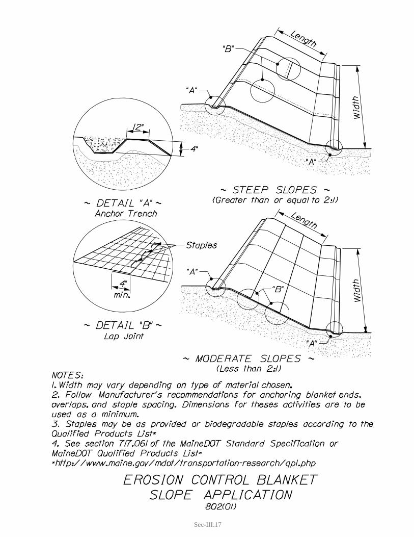
Sec-III:17

Sec-III:18
Sec-III:19
5. TURF REINFORCED MATTING (GEOTEXTILES)
Definition and PurposeTurf reinforced matting is a permanent vegetation reinforcement of permeable, synthetic, three-dimensional geotextile products that provides permanent increased strength to the surface layer of the soil and the vegetative cover.
Appropriate Applications
On slopes steeper than 3:1 where erosion hazard is high. fIn areas that would normally require riprap but where machine access is limited or where a fpermanent vegetative cover is desired.It is also used as a channel liner; see f Channel Linings (CF-EC).
Limitations
Material cost are usually more expensive than other permanent covers. fTurf reinforced matting are designed to work with vegetation; and vegetation must be maintained ffor the life of the project.
Standards and SpecificationsPermanent stabilization with turf reinforced matting shall be designed under the guidance of a fprofessional engineer.Must follow manufactures recommendations and be approved by the Resident. f
Application Procedures
Follow Manufacturer’s Guidelines and Specifications. f
Maintenance and Inspections
The Contractor shall inspect installation of turf reinforced matting weekly and before, during, fand after storm events until vegetative cover is established. Any failures shall be repaired immediately.Long term management of the vegetative cover is required. f

Sec-III:21
6. PlASTiC SheeTing
Definition and PurposePlastic sheeting is used for short duration protection of exposed soils or temporary cover of soil stockpiles. Woven and non-woven geotextile fabric may also be used.
Appropriate ApplicationsFor temporary stabilization on soil stockpiles or small areas of exposed soil for short periods of ftime, such as a sudden thunderstorm, until planned measures can be applied.
LimitationsPlastic sheeting results in 100% runoff, which may cause serious erosion problems in unstable fareas receiving the increased flow. Woven and non-woven geotextiles are an expensive option and if damaged in this application fmay be unusable for their intended applications.If not properly anchored, plastic sheeting and geotextile fabrics are susceptible to wind and if fdislodged can be a safety hazard, especially to the traveling public. Plastic sheeting is easily vandalized, cut, or torn. f
Standards and SpecificationsPlastic sheeting shall be polyethylene sheeting and shall have a minimum thickness of 4 mils. fPlastic sheeting may be reused if approved by the Resident. fAll woven and non-woven geotextile fabric may be used for this practice. fOverlap the sides of parallel rolls by 1 to 2 feet, upwind roll overlapping downwind roll. fOverlap the ends of rolls by 1 to 2 feet, uphill end over downhill end. fAll seams shall be taped, staked, or weighted down their entire length. fMaterial shall be properly anchored at edges, especially on the upwind side. Whenever possible, fadditional anchors should be evenly placed no more than 10 feet apart over entire surface to prevent ballooning of the surface.
Application ProceduresThe soil surface should be relatively smooth and free of protruding rocks and debris that can fpuncture and tear the sheeting.On slopes, unroll plastic sheeting down slope in the direction of runoff. fAnchor edges and seems as they are placed. f

Sec-III:22
Maintenance and InspectionsThe Contractor should inspect plastic sheeting used on stockpiles weekly and prior to, during, fand after storm events. Place additional anchors, as necessary, to prevent movement of plastic sheeting.If used for a single rainstorm event that includes high winds, maintain constant inspection against fdislodgement.
Sec-III:23
7. RIPRAP
Definition and Purpose Riprap is the designed placement of rock to protect the soil from all forms of erosion and geotechnical failure. It is used in the most severe conditions where other forms of stabilization are inadequate.
Appropriate Applications
On slopes steeper than 2:1. fOn slopes that can not be stabilized with vegetative cover due to slope length, contributing fwatershed, groundwater seepage, or poor soil conditions. Areas where soil is subject to high energy water flow with high erosive power such as stream fbanks, shorelines, ditch centers, culvert inlets and outlets.
Limitations
It is a permanent erosion control treatment and not typically used for temporary erosion control. fMaterial cost and site accessibility. fWhen riprap is placed on the shore of a waterbody, vegetation to shade the water will be difficult fto establish. This may cause an increase in water temperature.
Standards and Specifications
Permanent stabilization with riprap shall be designed under the guidance of an engineer. fRiprap and stone ditch protection shall meet the requirements of Materials Specification f703- Aggregates. Riprap should be well graded, having a range of rock sizes to fill the void spaces when placed. fUnless approved by an engineer, a filter material must be placed between the existing soil and friprap to maintain separation from the underlying soil. The most common filter is a non-woven geotextile fabric. Refer to Materials Specification 722 - Geotextile (Erosion Control Geotextile). A fine aggregate or gravel filter can also be used if properly sized. As a general rule, riprap thickness should be at least 1.5 times the D f 50 of the design rock gradation (D50 indicates the rock size whereby 50% by weight of the sample is smaller than the specified diameter.)
Application Procedures
Site should be graded smooth and free from all organic material. fPlace filter material (geotextile or aggregate) and secure. fPlace riprap with machinery, building from the bottom of the slope to the top. fRiprap should not be end-dumped from a truck or dropped for more than six feet, to prevent fseparation of sizes.
Sec-III:24
If placed in a watercourse, the bottom should be keyed into the bottom of the channel at least fone and a half times the normal thickness of the riprap and installed flush with the surrounding slopes.
Maintenance and Inspections
Riprap should be periodically inspected for slumping or bulging of the surface. f
References
Standard Specification 610 – Stone Fill, Riprap, Stone Blanket, and Stone Ditch Protection fStandard Specification 620 – Geotextiles fMaterials Specification 703.27 – Plain and Hand Laid Riprap fMaterials Specification 703.28 – Heavy Riprap fMaterials Specification 722.03 – Erosion Control Geotextile f
Sec-III:25
8. SEEDING AND LANDSCAPE PLANTINGS
Definition and Purpose Seeding provides a vegetative cover for temporary erosion control during construction or as a permanent measure to prevent sheet and rill erosion in the long term. Landscape plantings of trees, shrubs and other vegetation provide an immediately effective option for revegetation of a site. Seeding and landscape plantings also provide habitat and food for wildlife and shading of streams which benefits fisheries.
Appropriate Applications
Apply temporary seed to disturbed areas which will not be completed for more than 30 days. fApply permanent seed to all areas where long term vegetative cover is desired. fUse landscape plantings in areas where foot traffic is causing damage and needs to be fdiscouraged.Use landscape plantings to quickly re-establish mature vegetation damaged or removed during fconstruction, especially when located in a sensitive watershed or adjacent to a water resource.Use landscape plantings on areas where grasses may not be successful, such as steep or rocky fslopes or shaded areas.
Limitations
Seeded areas are vulnerable to erosion during the initial germination and establishment period. fSeeding and landscape plantings are susceptible to changing weather conditions (especially fsusceptible to drought) and are not applicable or effective during winter construction.
Standards and Specifications
Seeding shall be applied weekly unless otherwise indicated by Special Provision. fRefer to Standard Specification 618 - Seeding, or 621 - Landscaping. f
Application Procedures
Seeding shall be done in compliance with Standard Specification 618 - Seeding. fLandscape plantings shall be coordinated through the MaineDOT Landscape Unit and shall be in fcompliance with Standard Specification 621 Landscaping.
Sec-III:26
Maintenance and Inspection
Seeded areas shall be inspected weekly and before, during, and after each storm event to check ffor erosion. If necessary, additional mulch and/or seed shall be applied (mulch to cover 100% of disturbed soils, seed to achieve 90% coverage). Watering may be needed during the germination and the establishment period.Inspection and maintenance of landscape plantings shall be as specified under Standard fSpecification 621 - Landscaping.
References
Standard Specification 618 - Seeding fStandard Specification 621- Landscaping f

Sec-III:27
9. SURFACE ROUGHENING
Definition and PurposeSurface roughening is the practice of providing a rough soil surface with horizontal depressions for the purpose of reducing runoff velocity and encouraging infiltration. This will reduce the volume and depth of runoff and therefore the erosive power of the runoff.
There are two types of soil roughening methods:Tracking – is accomplished by tracked equipment traveling up and down the slope leaving cleat fmarks parallel to the contour (see figure 1).Grooving – is the process of tilling, disking, or harrowing across the slope leaving small ridges fparallel to the contour (see figure 2).
Appropriate Application
It should be used on constructed slopes where seeding, planting, or mulching are planned as the fpermanent cover and on graded areas with smooth, hard surfaces and a potential for erosion.
Limitations
Surface roughening may not be acceptable on slopes that will be mowed frequently. fGrooving should be limited to slopes flatter than 3:1 (H:V). Tracking is acceptable on slopes f2:1(H:V) and flatter.On soils with high clay content tracking can cause excessive surface compaction restricting fgrowing conditions for grass and landscape plantings. Surface roughening is not intended to be used as a stand alone BMP. Other forms of erosion and fsediment control must be used in conjunction with this BMP.
Standards and Specifications and Application ProceduresTracking - each pass of the equipment should overlap the previous pass, by the width of one ftrack, such that the entire sloped area is roughened. Cleat indents must run perpendicular the slope.Grooving - accomplished by cutting furrows perpendicular to the slope. Typical applications finclude using agricultural equipment such as tillers, or disk harrows. If slope is not to be mowed, grooves should no more than 15 inches apart and not less than 3 inches deep.
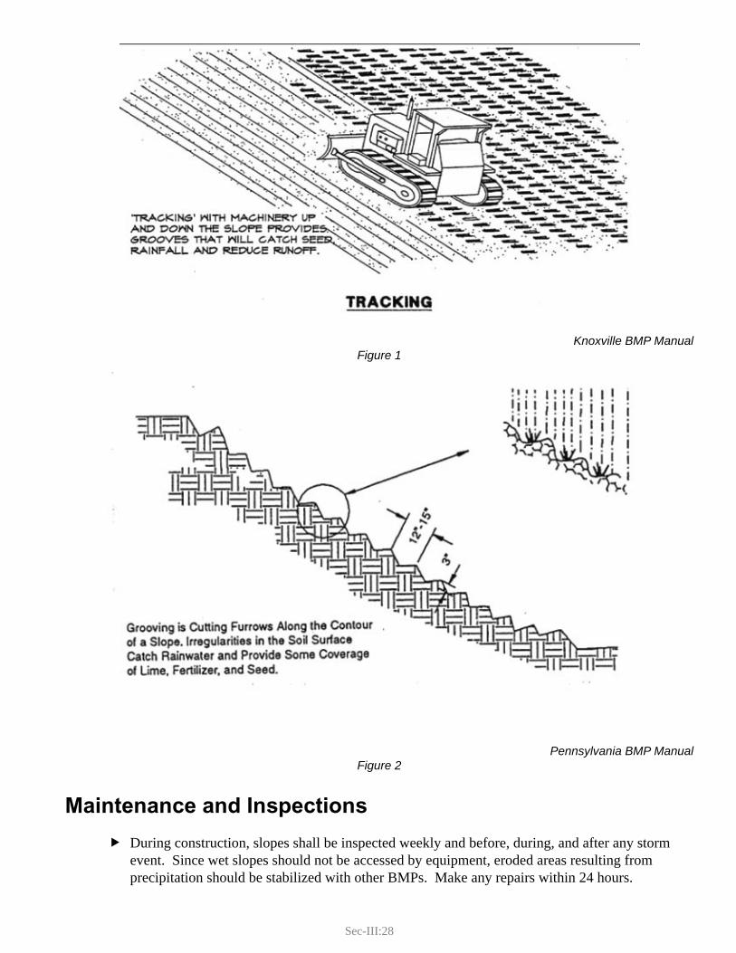
Sec-III:28
Knoxville BMP ManualFigure 1
Pennsylvania BMP ManualFigure 2
Maintenance and Inspections
During construction, slopes shall be inspected weekly and before, during, and after any storm fevent. Since wet slopes should not be accessed by equipment, eroded areas resulting from precipitation should be stabilized with other BMPs. Make any repairs within 24 hours.
Sec-III:29
10. GRADIENT TERRACE
Definition and PurposeGradient terraces are benches constructed into long slopes to interrupt surface runoff. By doing so it shortens the flow length over the slope and promotes infiltration. This will reduce the volume and depth of runoff and therefore the erosive power of the runoff.
Gradient terraces divert runoff from the slope face to a stable outlet.
They are intended as a permanent practice to protect a slope from slumping, sloughing, or excess ice build-up during winter months, but also help protect newly constructed vegetated slopes until vegetation is established.
Appropriate Applications
Gradient terraces are suitable for any slope that is susceptible to erosion. fGradient terraces are an excellent BMP for slopes that are designed to be vegetated but are fconstructed from late summer into the fall and will not have adequate time to establish vegetative root development before the end of the growing season.
Limitations
Gradient terracing is not intended to be used as a stand alone BMP. Other forms of erosion and fsediment control must be used in conjunction with this BMP. Site conditions such as right-of-way limitations, ledge, or design restrictions may limit the fpotential for altering slopes.
Standards and SpecificationsEach terrace must be sufficiently stabilized with an appropriate channel lining to handle fconcentrated flows. Terraces must also discharge to a stabilized area capable of handling flows without eroding.Terraces shall be a minimum of eight feet wide to provide for ease of maintenance. fTerraces shall be designed with a reverse slope of 6:1 or flatter to the toe of the upper slope and fwith a minimum depth of one foot, providing a shallow ditch for conveyance of water runoff. Terraces shall have a minimum longitudinal slope of 0.5% and maximum of 2.0% for drainage fpurposes, and shall convey runoff to a stable channel or outlet area such as a temporary slope drain or riprap downspout. Terraces shall be installed to the maximum vertical spacing shown in Table 1. f
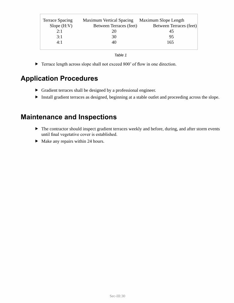
Sec-III:30
Table 1
Terrace length across slope shall not exceed 800’ of flow in one direction. f
Application Procedures
Gradient terraces shall be designed by a professional engineer. fInstall gradient terraces as designed, beginning at a stable outlet and proceeding across the slope. f
Maintenance and Inspections
The contractor should inspect gradient terraces weekly and before, during, and after storm events funtil final vegetative cover is established. Make any repairs within 24 hours. f
Terrace Spacing Maximum Vertical Spacing Maximum Slope Length Slope (H:V) Between Terraces (feet) Between Terraces (feet) 2:1 20 45 3:1 30 95 4:1 40 165
Sec-III:31
11. HILLSIDE DIVERSION
Definition and PurposeHillside diversions are constructed channels across the top of a slope with a supporting berm on the downhill side which is used to divert surface runoff away from the slope face, decreasing the watershed and therefore minimizing the depth of runoff and the erosive power of the runoff. They can be temporary practices until vegetation is established or as permanent practices for long term stabilization. Temporary hillside diversions are installed during construction to provide added protection to a seeded slope until the required percent vegetative cover has been established. Permanent hillside diversions are intended to provide a long term reduction in runoff volume. They are usually used where additional surface runoff volumes will hinder vegetation growth, or cause slope slumping, sloughing, or excess ice build-up during winter months.
Appropriate Applications
Hillside diversions are suitable for any slope that is susceptible to excess runoff from a fcontributing watershed. The primary application is to intercept sheet and shallow concentrated runoff, but if properly fdesigned they may be used to divert concentrated flow.
Limitations
Temporary hillside diversions are not intended to be used as a stand alone erosion control BMP. fOther forms of erosion and sediment control must be used in conjunction with it. Site conditions such as right-of-way limitations, ledge, or design restrictions may limit access to fthe top of the slope.
Standards and Specifications f Temporary Hillside Diversions
Refer to Standard Detail Drawing. yLocation should be determined by considering the outlet conditions, topography, land yuse, soil type, length of slope, groundwater seepage, (place below seeps and springs) and the project scope. A non-erosive channel lining (riprap, erosion control blanket, sheet plastic) shall be yinstalled. The outlet shall be stable and non-erosive, typically a temporary slope drain. yDesign must be approved by the Resident. y
Sec-III:32
Permanent Hillside Diversions fShall be designed by an engineer. yShall be designed to carry a minimum of the 10 year, 24 hour flow with a minimum yfreeboard of six inches.If failure of the diversion may cause property damage it shall be designed to carry a yhigher frequency storm event.The channel lining should be vegetated. If site conditions will not support vegetation, yriprap is acceptable. The outlet shall be stable and non-erosive, typically a riprap downspout. yCross sectional areas may be constructed by cut and fill. See standard drawing. y
Application Procedures
Install hillside diversion as designed, beginning at a stable outlet and proceeding up hill. fThe diversion shall be excavated or shaped to line, grade, and cross-section as required meeting fthe criteria specified, free of irregularities which will impede flow.Fills shall be compacted by equipment to prevent unequal settlement that may cause dam age in fthe completed diversion.All earth removed and not needed in construction shall be reused or disposed of and stabi lized so fthat it will not interfere with the functioning of the diversion.All constructed channel sections shall be stabilized by the end of the work day. f
Maintenance and Inspections
Temporary hillside diversions shall be inspected weekly and before, during, and after storm fevents throughout the life of the practice. Permanent hillside diversions shall be inspected weekly and before, during, and after storm fevents until final cover is established. Special care should be taken in areas where there is a change in channel grade. fMake repairs within 24 hours. f
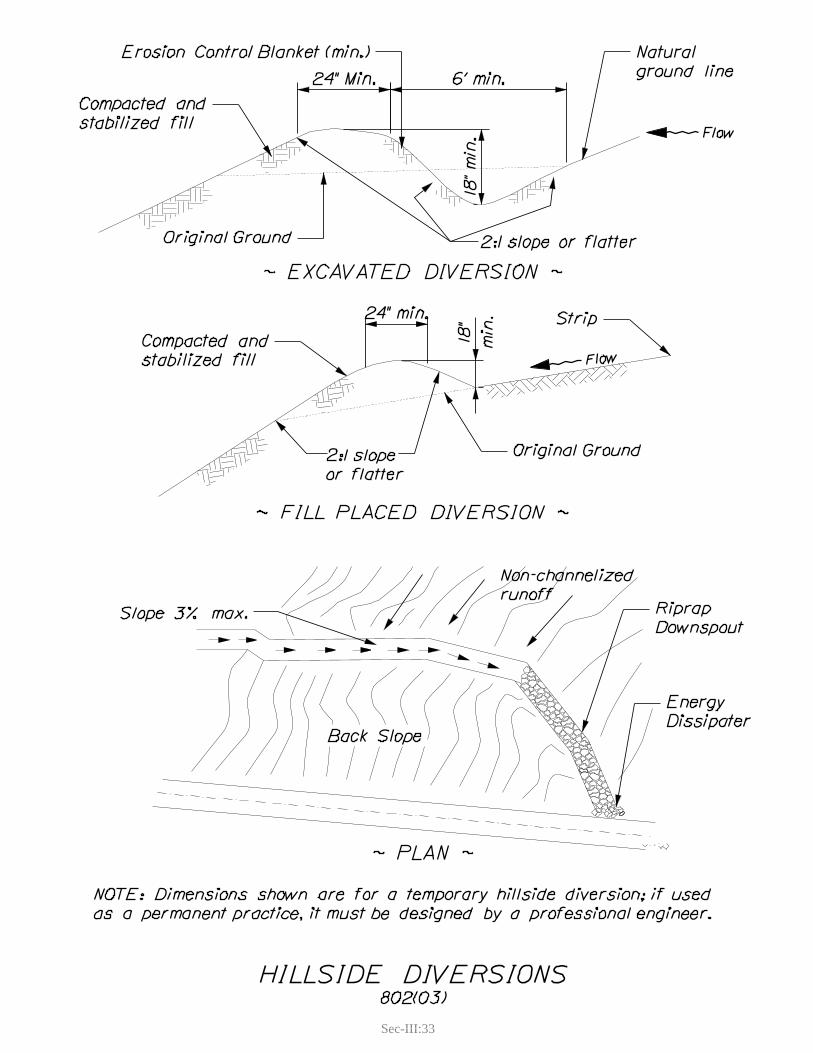
Sec-III:33

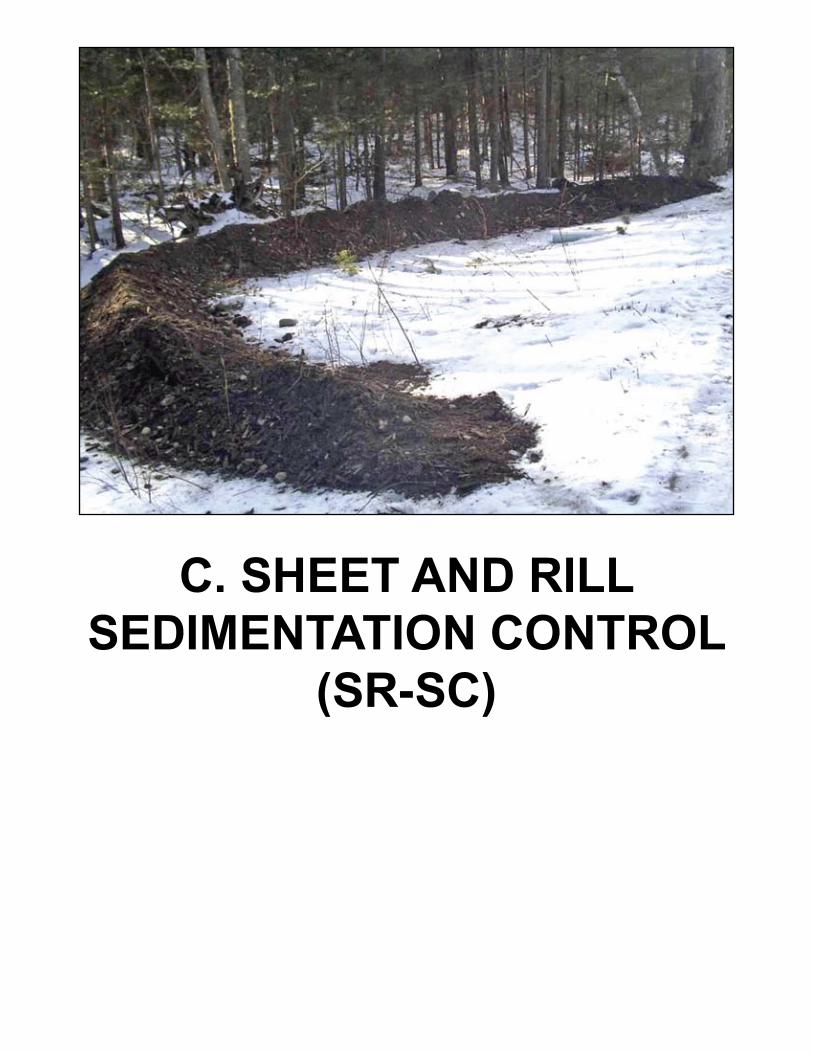
C. SHEET AND RILL SEDIMENTATION CONTROL
(SR-SC)


Sec-III:37
C. SHEET AND RILL SEDIMENTATION CONTROL (SR-SC)Sedimentation control is the last line of defense. If there is a possibility of erosion occurring on a construction site, a sedimentation control BMP should be installed. The primary function of sedimentation control is to decrease the velocity (power) of water for a long enough time to allow individual sediment particles to settle out. Some sedimentation control BMPs also filter sediment, in addition to settling them out.
Sedimentation control BMPs do not stop erosion from occurring, they prevent sediment from leaving the site. In addition, they are not effective at settling out fine textured soils (silts and clay). Sedimentation control BMPs should always be used in partnership with erosion control BMPs.
The type of sedimentation control BMP is dictated by the type of erosion that occurs. The BMPs in this section will provide sedimentation control for sheet and rill erosion. Distinguishing between raindrop erosion and sheet erosion is difficult so raindrop erosion is also included in this section.
The BMPs in this section will help to contain sediments generated by the processes of rainfall, sheet, and rill erosion. They are designed to work over a broad area and on the contour. The first three are designed to be placed along the contour, capture sheet flow, decrease the velocity (power), and allow sediment to settle out. The filter strip treats sheet and rill run off by infiltrating runoff water, and physically filtering sediment.
Silt Fence fErosion Control Mix Berm fContinuous Contained Berms fVegetated Filter strip f

Sec-III:39
1. SILT FENCE
Definition and PurposeSilt fence is a temporary sediment-retaining barrier of permeable geotextile fabric. Silt fence is designed to pond sediment laden water, reducing the flow velocity for a long enough period of time to promote settlement of sediment. Silt fence is not designed to filter fine sediment through the fabric
Appropriate Applications
Downhill edge of disturbed slopes. fPerimeter protection around soil stockpiles. f
Limitations
Not intended for areas receiving concentrated flows of water (i.e., ditches, downspouts, drainage fswales, or streams).Can be difficult to properly install in shallow-to-ledge, stony, or forested ground. fSilt fence does not filter fine soil particles, although it will filter particles larger than medium fsized sand. It functions by ponding water and allowing sediment to settle out. If flow through time through ponded area is too short, silts and clays may pass through silt fence, uncontained. Must be removed and disposed of after disturbed site is stabilized. fShall be in a location where it can be accessed for maintenance. fGeotextile fabric will degrade depending on amount of exposure to the sun. Functional life span fof silt fence is approximately one field season.
Standards and SpecificationsRefer to Standard Detail Drawing. fSilt fence shall be placed along a contour, to provide maximum storage capacity and limit flow fparallel to the fence. Silt fence should have a relatively level area immediately up-gradient to provide an area for fponding. Maximum uphill drainage area should not exceed 100 feet in length as measured perpendicular fto fence. Do not use below slopes that are subject to slumping. fRefer to the MaineDOT Approved Product List – Geotextile for Materials Specification. f
Application Procedures
Bottom flap of silt fence shall be keyed into the ground a minimum 6” in depth. Alternatively, in fareas where it is not practicable to key in the flap, it can be anchored with Aggregate for Crushed Stone Surface (Materials Specification 703.12), Erosion Control Mix, or other material approved by the Resident. Flap shall be anchored sufficiently to resist pull out.
Sec-III:40
Anchor posts shall be spaced a maximum of 8 feet apart and driven approximately 18 inches into fthe ground.Joints between separate pieces of silt fence shall be spliced together by wrapping the two end fposts together as shown in Standard Detail drawing.End sections of silt fence shall be curved uphill to a point that the base of last post is at or above fthe elevation of the top of the fence on the contoured length.
Maintenance and Inspection
Silt fence requires frequent inspection and maintenance. Inspections shall be conducted weekly and before, during, and after each storm event.
Inspections should look for the following: fFailure under fence. ySlumping or torn sections of fence. yBreakage or movement of stakes. ySections where significant amounts of sediment have accumulated. y
When sediment reaches half the height of a silt fence the sediment shall be removed immediately fand disposed of in an approved location.Repairs to silt fence shall be made within 24 hours of the time they were first noted. fSilt Fence shall be removed once permanent stabilization has been achieved on uphill disturbed fareas. Disturbed ground resulting from removal shall be leveled and stabilized.
References
MaineDOT Approved Product List: http://www.maine.gov/mdot/transportation-research/ fapproved-products.phpMaterials Specification 703.12 - Aggregate for Crushed Stone Surface fMaterials Specification 717.04(d) – Erosion Control Mix f
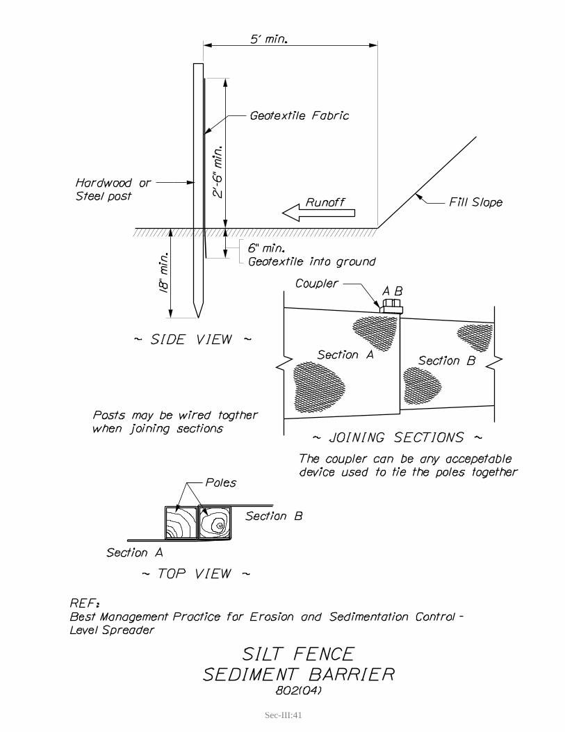
Sec-III:41

Sec-III:43
2. EROSION CONTROL MIX BERM
Definition and PurposeErosion control mix berm is a temporary sediment-retaining barrier consisting of a continuous berm made of erosion control mix. The erosion control mix berm is designed to pond sediment laden water, reducing the flow velocity for a long enough period of time to promote settlement of sediment. It is not designed to filter sediment through the structure although new research indicates that the berm will provide filtering of sediment.
Appropriate Applications
Down hill edge of disturbed slopes. fPerimeter protection around soil stockpiles. fOften used on sites where silt fence is difficult to install (i.e., shallow ledge, or stony soils). f
Limitations
Not intended for areas receiving concentrated flows (i.e., ditches, downspouts, drainage swales for streams). Must be maintained. fMust be in a location where it can be accessed for maintenance. f
Standards and SpecificationsErosion control mix berms shall be placed along a contour, to provide maximum storage capacity fand limit flow parallel to the berm.Erosion control mix berms should have a relatively level area immediately up-gradient to provide fan area for ponding. This area should be as wide as practicable.Maximum uphill drainage area should not exceed 100 feet as measured perpendicular to berm. fFor erosion control mix berm sizing see Figure 1. fSide slopes of the berm shall be no steeper than 1:1. fBerms shall consist of erosion control mix, meeting Materials Specification 717.04 (d). fAlternative materials may be approved by the Resident on a case-by-case basis.
Application Procedures
Cut tall grasses and woody vegetation from application area to prevent short circuiting of flow funder berm.Material may be placed by hand, machinery, or pneumatic blower. fEnd sections of erosion control mix berms shall be curved uphill to a point that the base of the fend sections is at or above the elevation of the top of the berm along the contoured length.
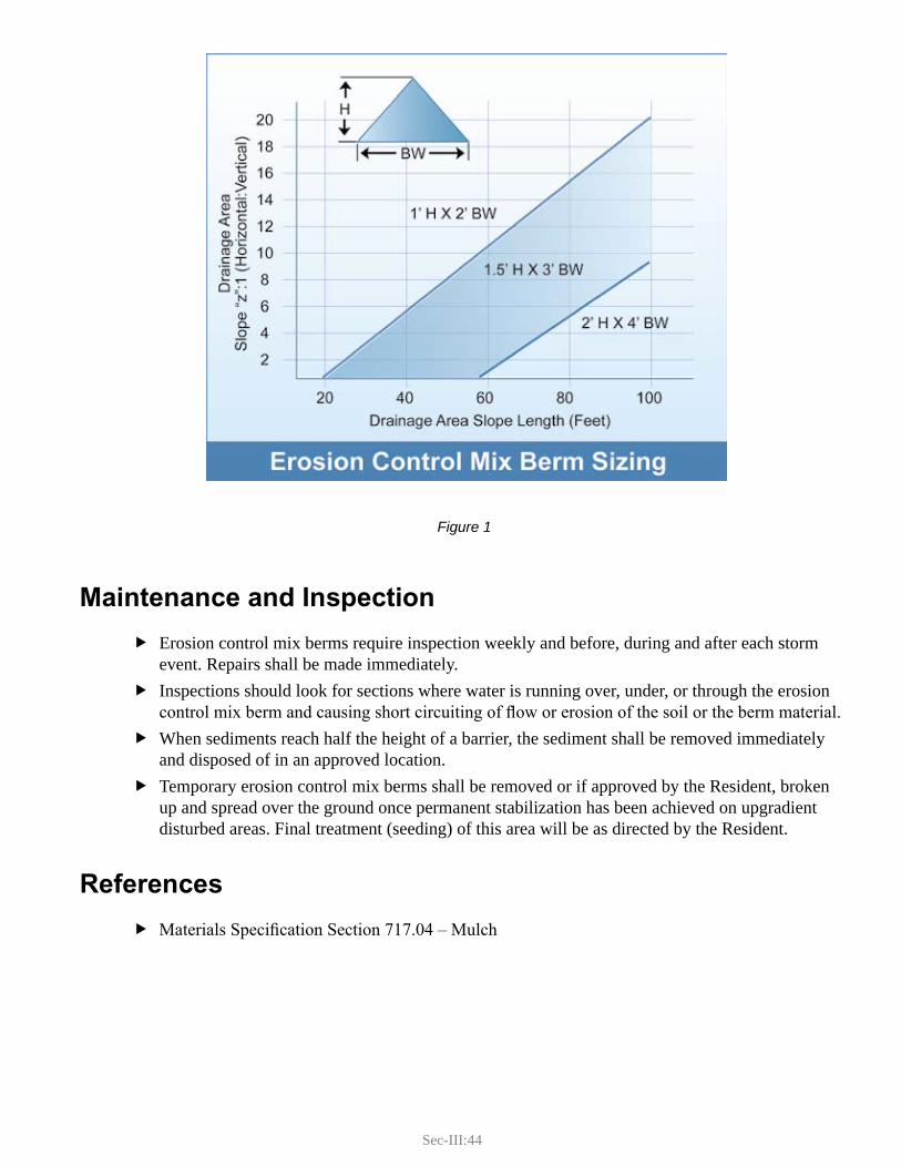
Sec-III:44
Figure 1
Maintenance and Inspection
Erosion control mix berms require inspection weekly and before, during and after each storm fevent. Repairs shall be made immediately.Inspections should look for sections where water is running over, under, or through the erosion fcontrol mix berm and causing short circuiting of flow or erosion of the soil or the berm material. When sediments reach half the height of a barrier, the sediment shall be removed immediately fand disposed of in an approved location. Temporary erosion control mix berms shall be removed or if approved by the Resident, broken fup and spread over the ground once permanent stabilization has been achieved on upgradient disturbed areas. Final treatment (seeding) of this area will be as directed by the Resident.
References
Materials Specification Section 717.04 – Mulch f
Sec-III:45
3. CONTINUOUS CONTAINED BERM
Definition and PurposeContinuous contained berms are manufactured temporary sediment-retaining barriers that are bound in a tubular roll. The continuous containment berm is designed to pond sediment laden water, reducing the flow velocity for a long enough period of time to promote settlement of sediment. Current products on the market include a geotextile mesh tubular sock filled with wood based material (similar to erosion control mix), and fiber rolls composed of straw, flax, or other similar material.
Appropriate Applications
Install down slope of small disturbed areas. fUse as perimeter protection around soil stockpiles. fInstall around drainage inlets and outlets. fThese products are most effective at directing flow and protecting outlets from flow on the road fgrade or from bridge decks where flow depths are low and the flexibility of the product can be used during the various stages of changing road grade.
Limitations
Currently a compost filled geotextile sock produced by Filtrexx ® is accepted on a trial basis in fMaine. Use of this or any other products must be approved by the Resident. In a standard application these products do not provide the same height of ponded water as silt ffence or erosion control mix berm and therefore will not have the same settling capacity.If full contact with the ground is not achieved, there is a potential for short circuiting flow under fthe product that may cause erosion of the underlying soil.
Standards and SpecificationsFollow Manufacturer’s Guidelines and Specifications. f
Application Procedures
Prepare existing ground surface as needed to achieve a smooth surface for maximum contact farea.Install the berm along a contour, to promote continued sheet flow and provide maximum storage fcapacity. Barriers not placed along a contour will tend to concentrate runoff toward low spots, which are much more prone to failure.End sections of continuous containment berm shall be curved uphill to a point that the base of fend section is at or above the elevation of the top of the berm along the contoured length.Continuous containment berm may be placed by hand or machinery; the sock may be filled by fpneumatic blower onsite.
Sec-III:46
Maintenance and Inspection
Continuous containment berms require frequent inspection and maintenance. Inspections shall be conducted weekly as well as before, during, and after each storm event. The berms should be checked daily during extended periods of rain.
Inspections should look for the following: fSections where water is running over or under the continuous containment berm and ycausing short circuiting of flow.Torn or degraded fabric. yAreas where vehicles have run over continuous containment berms. y
When sediments reach half the height of a continuous containment berm, the sediment shall be fremoved immediately and disposed of in an approved location.Repairs to continuous containment berm shall be made within 24 hours of the time they were ffirst noted.Unless the continuous containment berm is composed of biodegradable material it should be fremoved once permanent stabilization has been achieved on the uphill disturbed area.
References
Manufacturer’s Guidelines and Specifications f
Sec-III:47
4. VEGETATIVE FILTER STRIP
Definition and PurposeA filter strip is a natural, undisturbed vegetated area that will remove sediment by reducing flow velocity, promoting infiltration, and allowing sedimentation to occur by physically trapping soil particles within the vegetation.
Filter strips are typically used for post construction permanent stormwater treatment but may be used below disturbed areas with short flow lengths such as road cross slope, shoulders, and inslopes.
For post construction permanent stormwater treatment, contact the Surface Water Quality Unit.
Appropriate Applications
When disturbed areas are small, runoff is in sheet flow only, and concentrated flow does not foccur until after flow through the filter. This application shall be approved by the Resident.
Limitations
Use of a filter strip may be limited by extent of right-of-way. fFilter strip areas must be in established vegetated areas. Newly vegetated areas are not permitted. fRunoff must enter the filter as sheet flow. Rill or concentrated flow is not allowed. fFilter effectiveness will vary depending upon slope, underlying soils, the type and density of the fvegetation, and the amount of flow into the filter.Wetlands are not acceptable as filter strips. f
Standards and SpecificationsThe filter strip area shall be undisturbed. No construction activities shall be allowed within the ffilter strip area.The contributing disturbed area shall be a maximum of 25 feet with no more than 10 feet being fgreater than 5:1 (inslopes). The filter strip shall have a slope of less than 33% (3:1). The optimum gradient within the filter fstrip is 1 to 2% (100:1 to 50:1).The filter strip area must be an established vegetated area of either grass or woody vegetation and fmust be healthy and have a vigorous growth habit.Grass filter strips must be meadow or field. Maintained lawns are not recommended and must be fapproved by the Resident. Wooded and shrub filter strips must have a cover of duff, leaf litter, and roots that completely fcover the ground surface. From the top of the filter strip on the contour, the slope lengths should not converge i.e. the shape fof the contour line should be constant or diverge. Refer to Table 1 for recommended filter strip lengths. f
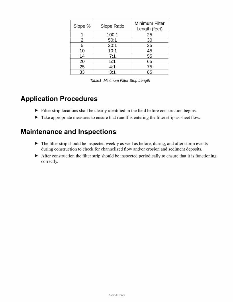
Sec-III:48
Table1 Minimum Filter Strip Length
Application Procedures
Filter strip locations shall be clearly identified in the field before construction begins. fTake appropriate measures to ensure that runoff is entering the filter strip as sheet flow. f
Maintenance and Inspections
The filter strip should be inspected weekly as well as before, during, and after storm events fduring construction to check for channelized flow and/or erosion and sediment deposits. After construction the filter strip should be inspected periodically to ensure that it is functioning fcorrectly.
Slope % Slope Ratio Minimum Filter Length (feet)
1 100:1 252 50:1 305 20:1 3510 10:1 4514 7:1 5520 5:1 6525 4:1 7533 3:1 85

D. CONCENTRATED FLOW EROSION CONTROL
(CF-EC)

Sec-III:51
D. CONCENTRATED FLOW EROSION CONTROL (CF-EC)Gully erosion begins when runoff concentrates with enough depth and velocity to cut into the soil to a depth of one foot or more. On transportation projects gully erosion usually occurs within constructed channels or where a large volume of water is concentrated and allowed to flow over unprotected soil. The BMPs in this section will address these types of situations by:
Protecting the channel lining from high velocities. fProtecting the inlet and outlet slopes around culverts, and underdrain outlets from scour. fDecreasing the erosive power by slowing the velocity of water as it exits high velocity fconcentrated flow structures: (culverts, downspouts or ditches).Decreasing the erosive power by decreasing the volume (depth) of water flowing in a channel. f
The BMPs in this section include:
Channel Linings fTemporary Channel Lining - Plastic Sheeting fRiprap Downspout fTemporary Slope Drain fEnergy Dissipators fCulverts - Inlet/Outlet Protection f

Sec-III:53
1. CHANNEL LININGS
Definition and PurposeChannel linings are armoring techniques that protect permanent concentrated flow channels from erosion. There are two basic types of channel lining; vegetated (grass) or stone-lined. Other treatments may be used on a case-by-case basis.
Appropriate Applications
Grass is adequate when flow velocities and depths of flow are low enough to not cause erosion of fthe channel. Stone should be used when grass is not adequate to protect the channel from erosion or where fthere are adverse growing conditions such as poor quality or saturated soils. Although their primary function is stormwater conveyance, a grass-lined channel on a grade at or fbelow 1% also provides limited filtering of sediment and pollutants, which may be of benefit to downstream water bodies.
Limitations
This standard is not to be used for stream channel linings or stream bank protection. fRoad sand and/or salt can smother grass or create conditions that inhibit growth. fStone-lined channels are generally more expensive than grass-lined channels. fStone-lined channels may not be preferred from an aesthetic or environmental perspective. fAlternatives such as the use of turf reinforced matting may be used. Consult a design engineer or the SWQU.
Standards and SpecificationsChannel linings shall be designed to withstand, as a minimum, the flow from a 10-year, 24-hour fstorm event. For channels with grades 0-6% grass is usually adequate for long term protection.
During construction and until grass cover has fully established it must be protected from yflowing water by installing Erosion Control Blanket.Refer to Standard Detail Drawing. yInstall within one week of completed grading. In sensitive watersheds daily application yof temporary mulching may be required prior to installation of erosion control blanket.Spacing of anchors shall be placed at a maximum spacing of 3 feet on center or as yrequired by the manufacturer, whichever is closer. Seed according to design, either Method 1 or Method 2 as specified in Standard ySpecification 618 – Seeding. Method 3 is unacceptable for channels.
For channels with grades less than 6% but with long duration flows that make grass festablishment and maintenance difficult, (low lying areas with a high water table, continuously flowing underdrains or springs) stone lining may be needed - consult a design engineer or the SWQU.
Sec-III:54
For channels with grades over 6% install stone in the bottom to a minimum width of one third fthe top width.
Refer to Highway Design Guide Volume 1, Chapter 12, Drainage Design for channel ydesign. Stone gradation for most road ditches shall be in accordance with Materials Specification y703.29 – Stone Ditch Protection. Geotextile installed under the stone shall comply with Standard Specification 620 - yGeotextiles.
Other treatments such as turf reinforced matting or articulating concrete blocks may be used with fthe approval of the Resident.
Application Procedures
If water is present in the channel, divert runoff from the channel while it is under construction. fConstruct the channel in sections, beginning at the outlet. f
Stabilize the channel outlet per plans and cross-sections (i.e. level spreader, ditch turn- yout, riprap apron, etc.).Excavate to the required lines and grades for the channel. yInstall the appropriate channel lining. y
For grass-lined channels, fine grade the channel; if design calls for it apply loam. xApply seed and fertilizer according to Seeding Specification. Before the end of the day, install the erosion control blanket in the channel bottom and mulch the remainder; see Hay and Straw Mulch or Hydraulic Mulches.For stone-lined channels, install geotextile and then the stone. x
Maintenance and Inspections
The Contractor should inspect grass-lined channels weekly and prior to, during, and after storm fevents to check for erosion. Any failures shall be repaired immediately by regrading, reapplying seed, and covering with erosion control blanket and/or mulch. The contractor shall maintain erosion control blankets and mulch until new grass covers at least 90% of the soil surface. Grass is not considered established until ground cover is mature enough to withstand the erosive forces of channel flow.The Contractor should inspect stone-lined channels weekly to check for movement of the stone fand/or erosion. Repairs shall be made immediately.
References
Standard Specification 613 – Erosion Control Blankets fStandard Specification 610 – Stone Fill, Riprap, Stone Blanket, and Stone Ditch Protection fMaterials Specification 717.061 – Erosion Control Blanket fMaterials Specification 703.29 – Stone Ditch Protection fMaine Highway Design Guide, May 2002 f
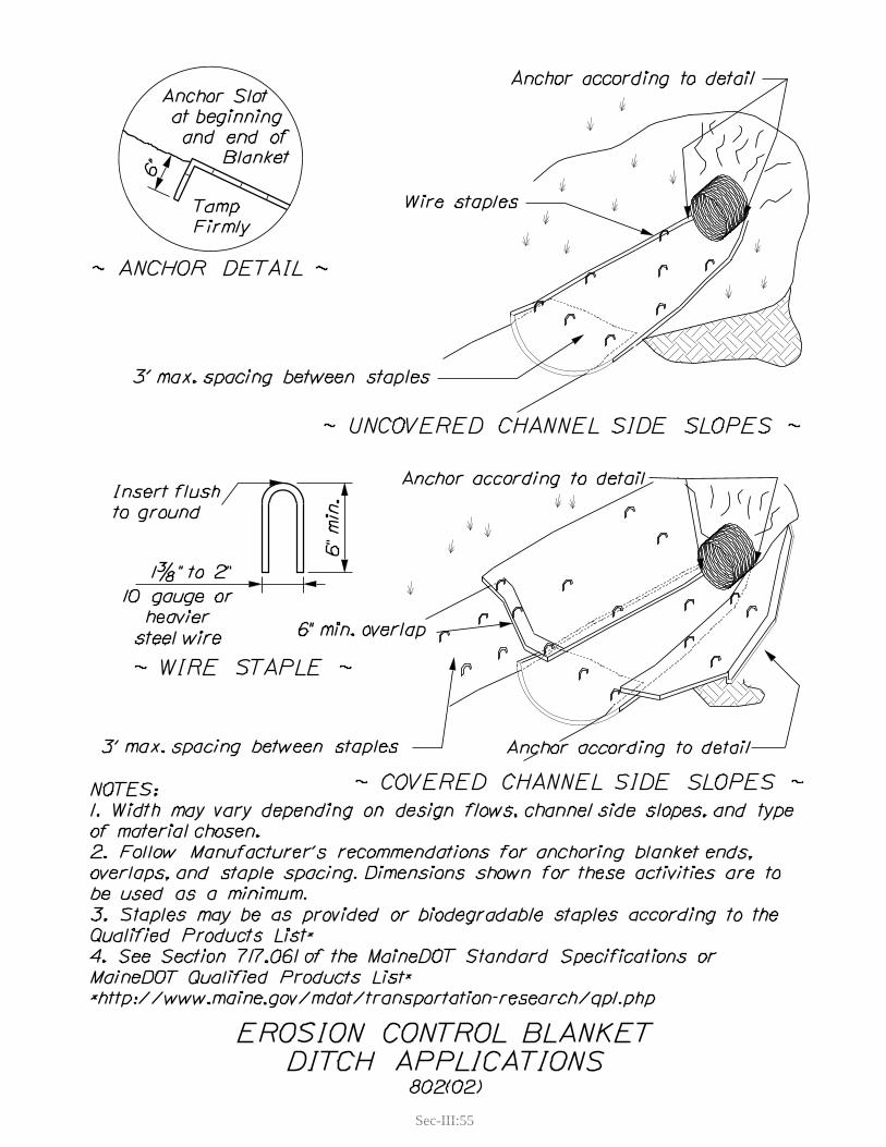
Sec-III:55

Sec-III:57
2. TEMPORARY CHANNEL LINING - PLASTIC SHEETING
Definition and PurposeTemporary channel lining - plastic sheeting is a method of armoring a concentrated flow channel that has been constructed and will be removed before final project completion or, in emergency situations a permanent channel lining has not been installed and the channel is exposed to concentrated flow.
Appropriate Applications
A temporary hillside diversion lining. fFor temporary stream diversion channel see f Temporary Stream Diversion (IN WATER).Any other constructed channel that will temporarily carry concentrated flows and has not been fprotected by other means.
Limitations
Plastic sheeting is difficult to install during high wind. fIf not properly anchored, plastic sheeting and geotextile fabrics are susceptible to wind and if fdislodged can be a severe safety hazard, especially to the traveling public.Plastic sheeting is easily vandalized, cut, or torn. f
Standards and SpecificationsChannel cross section may be formed by excavating, or by placing a berm of earthen fill, gravel, fsandbags or other material that will resist lateral movement during anticipated high flows in the channel. Plastic sheeting shall be polyethylene sheeting and shall have a minimum thickness of 4 mils. fOther materials such as woven or non-woven geotextile may be used with the approval of the Resident. Material shall be wide enough to extend over top edge of channel with enough slack to provide fadequate anchoring.Anchoring - The edges of plastic sheeting should be toed into the soil or anchored with non- ferodible ballast i.e., crushed stone, sand-bags, or other suitable materials. Anchoring should be continuous throughout the channel length.If more than one roll of sheeting is used in the channel, the upstream roll shall overlap the fdownstream roll by a minimum of 2 feet and the seam shall be adequately anchored.

Sec-III:58
Application Procedures
Shape channel area where sheeting will be applied, to provide a relatively smooth surface. fRemove any projections that could puncture or tear sheeting during deployment.Unroll plastic sheeting in channel section and apply anchoring to all edges and seams. f
Maintenance and Inspection
The Contractor should inspect plastic sheeting weekly and before, during, and after storm events ffor stability and indication of flow bypass. Place additional anchors, as necessary.
Sec-III:59
3. RIPRAP DOWNSPOUT
Definition and PurposeA riprap downspout is a permanent armored channel that conveys concentrated runoff down a steep slope to a stable outlet area without causing erosion. Downspouts typically involve high velocity water flow and therefore require significant armoring to prevent scouring.
Appropriate Applications
To convey concentrated flow road runoff down a steep inslope. Typically at the end of a curbed fsection of road, at bridge abutments, or at a sags (low point) in a road.To convey surface water runoff down a backslope. Sources include seeps, spring runoff, and fwater from hillside diversions. Not to be used for diverting stream channels. f
Limitations
High velocity flow can be unstable flow. Any in-channel obstructions can cause water to jump fout of bank. Channel cross section must remain smooth. Obstructions can be ice build-up, debris, or a misplaced rock. For high velocity flow, the riprap downspout must be installed with an energy dissipator at the foutlet to prevent scour. Depending on the road grade, high velocity flows may bypass downspout inlet. Conveying water finto the downspout may require reshaping of the road grade or installing a structural diverter.
Standards and SpecificationsRefer to Standard Detail Drawing. fIf the drainage area is greater than 0.5 acres of road section, 1.5 acres of lawn (light fdevelopment), or 3 acres of forest (undeveloped) then the downspout design shall be approved by an engineer. The downspout shall discharge to a stabilized area capable of handling flows without eroding; fsee Energy Dissipator.The downspout shape shall be trapezoidal or parabolic in cross-section. fFor road grade runoff, the inlet of the downspout shall be depressed to direct water into it. fRiprap shall be underlain with non-woven geotextile according to Materials Specification 722.03 f- Erosion Control Geotextile.Riprap shall be according to Materials Specification 703.26 - Plain and Hand Laid Riprap, fThe downspout shall be installed perpendicular to the slope and the maximum slope shall be no fmore than 2:1 unless designed by an engineer.
Sec-III:60
Application Procedures
Install the downspout during dry conditions. fMake sure the inlet is depressed and stabilized to direct water into the downspout. fInstall an energy dissipator at the outlet. f
Maintenance and Inspections
During project construction, inspect the downspout weekly and before, during, and after storm fevents. Make any needed repairs within 24 hours. Inspect periodically to check for erosion at the outlet area and stability of the channel itself. Remove any debris blocking or diverting flow in the downspout.
References
Standard Specification 610 – Stone Fill, Riprap, Stone Blanket, and Stone Ditch Protection fStandard Specification 620 – Geotextiles fMaterials Specification 703.26 – Plain and Hand Laid Riprap fMaterials Specification 722.03 – Erosion Control Geotextile f

Sec-III:61

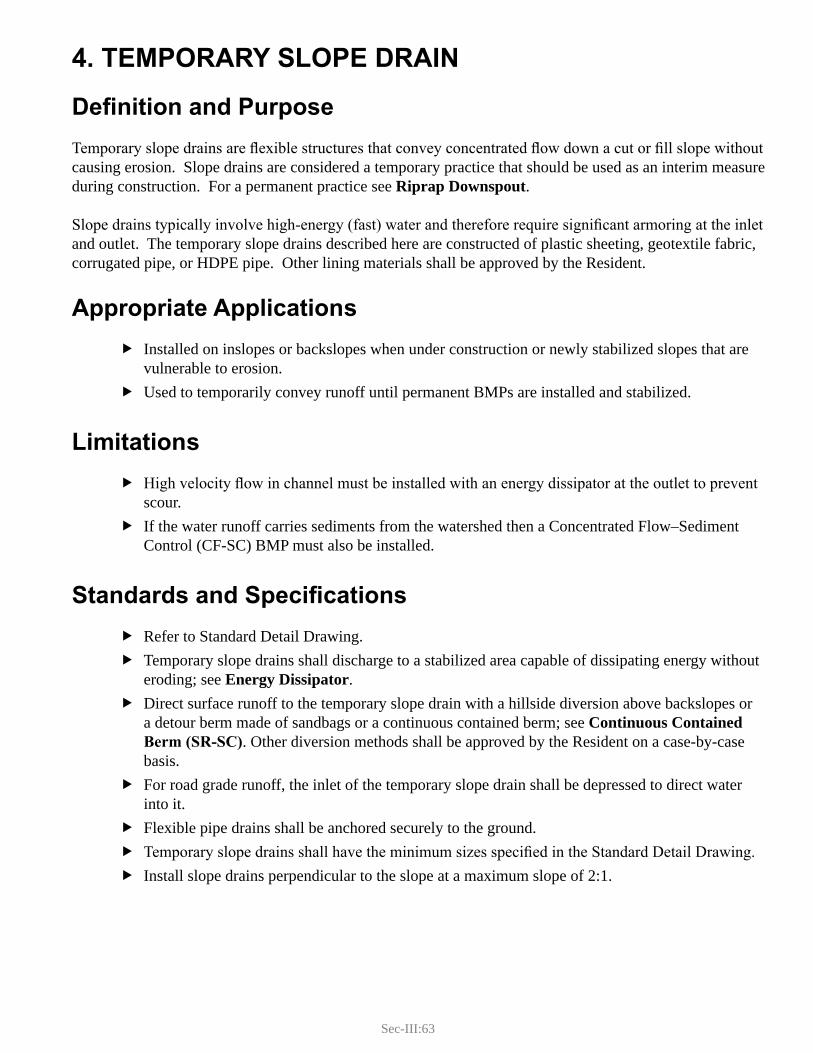
Sec-III:63
4. TEMPORARY SLOPE DRAIN
Definition and PurposeTemporary slope drains are flexible structures that convey concentrated flow down a cut or fill slope without causing erosion. Slope drains are considered a temporary practice that should be used as an interim measure during construction. For a permanent practice see Riprap Downspout.
Slope drains typically involve high-energy (fast) water and therefore require significant armoring at the inlet and outlet. The temporary slope drains described here are constructed of plastic sheeting, geotextile fabric, corrugated pipe, or HDPE pipe. Other lining materials shall be approved by the Resident.
Appropriate Applications
Installed on inslopes or backslopes when under construction or newly stabilized slopes that are fvulnerable to erosion.Used to temporarily convey runoff until permanent BMPs are installed and stabilized. f
Limitations
High velocity flow in channel must be installed with an energy dissipator at the outlet to prevent fscour. If the water runoff carries sediments from the watershed then a Concentrated Flow–Sediment fControl (CF-SC) BMP must also be installed.
Standards and SpecificationsRefer to Standard Detail Drawing. fTemporary slope drains shall discharge to a stabilized area capable of dissipating energy without feroding; see Energy Dissipator. Direct surface runoff to the temporary slope drain with a hillside diversion above backslopes or fa detour berm made of sandbags or a continuous contained berm; see Continuous Contained Berm (SR-SC). Other diversion methods shall be approved by the Resident on a case-by-case basis.For road grade runoff, the inlet of the temporary slope drain shall be depressed to direct water finto it. Flexible pipe drains shall be anchored securely to the ground. fTemporary slope drains shall have the minimum sizes specified in the Standard Detail Drawing. fInstall slope drains perpendicular to the slope at a maximum slope of 2:1. f

Sec-III:64
Watershed shall not exceed the following areas: f
Application Procedures
Install the temporary slope drain during dry conditions. The inlet shall be entrenched to prevent fwater flowing underneath the drain.Immediately install inlet and outlet protection. fInstall detour berm at inlet to direct surface runoff into the temporary slope drain. fMake all pipe connections watertight. fWhen temporary slope drain is removed, stabilize any remaining disturbed areas. f
Maintenance and Inspections
Inspect weekly as well as before, during, and after storm events. Ensure that runoff is not fbypassing the structure. Check for erosion at the inlet and outlet areas. Also check for debris clogging the drain. Make any needed repairs immediately.
Maximum Allowable Drainage Area (ac)
Temporary Slope Drain Forest (undeveloped)
Lawn (light development)
Impervious (road surface or parking lots)
12 inch Pipe 1.0 0.4 0.218 inch Pipe 1.2 0.5 0.23 foot Plastic Sheet 2.8 1.2 0.5

Sec-III:65
Sec-III:66
Sec-III:67
5. ENERGY DISSIPATORS
Definition and PurposeEnergy dissipators consist of riprap armoring at flow transition areas (high energy to low energy) to dissipate energy and prevent scouring of the downstream channel. They are typically specified at pipe outlets and/or swale transitions from steeper to flatter grades.
Energy dissipators are generally considered permanent structures but they may also be implemented as a temporary structure for temporary water diversion systems.
Appropriate Applications
Where high velocity channelized flow outlets to a channel that may be subject to scour erosion. fExamples include:
pipe outlets. yriprap downspouts. ytemporary slope drains. yunderdrain outlets. y
Limitations
Common usage of this specification is not intended for flows exceeding 50 cfs; it is generally for fpipe diameters 36 inches or less. Flows exceeding 50 cfs must be designed by an engineer.Not to be used in a natural stream channel unless specifically approved by the SWQU staff; see fIn-Water Work section. If fish passage is a concern, refer to MaineDOT Waterway and Wildlife Crossing Policy and Design Guide. These devices are not intended to provide sedimentation control. Sediment is often observed fin these structures but is typically re-suspended and washed downstream by the next significant storm event.
Standards and SpecificationsThere are two primary types of energy dissipators addressed in this manual: a riprap apron and a friprap plunge pool. Other methods proposed by the contractor must be individually approved by the Resident. Determining which type of energy dissipator depends on amount of flow, grade, and type of fdownstream channel. Typically aprons are used for lower flow conditions at the outlets of smaller pipes such as driveway culverts and underdrain outlets. Plunge pools are better at dissipating higher energies and transitioning the flow to better conform to existing downstream channel conditions. Refer to Standard Detail Drawing for dimensions. f
Sec-III:68
Riprap Apron f
Riprap shall be underlain with non-woven geotextile according to Materials Specification y722.03 - Erosion Control Geotextile.Riprap shall be according to Materials Specification 703.29 - Stone Ditch Protection. yFor application with culverts, riprap shall extend at least six inches under the culvert yinvert.Apron surface shall be rough, with many of the larger stones projecting into flow area. yLength = 4.5 x Diameter for pipes or 4.5 x top width of incoming flow channel. yWidth = 3 x Diameter for pipes or 3 x top width of incoming flow channel. yThe apron shall be installed at a 0% grade. If site conditions limit the ability to install at ythis grade, consider the use of a plunge pool.The apron shall be shaped so that the centerline invert is slightly lower than the edges to yprevent flow from splitting around the apron and eroding the earth beside the apron.
Plunge Pool f
Riprap shall be underlain with non-woven geotextile according to Materials Specification y722.03 - Erosion Control Geotextile.Riprap shall be according to Materials Specification 703.26 - Plain and Hand Laid yRiprap. For application with culverts, riprap shall extend at least six inches under the culvert yinvert.Rule of Thumb for sizing plunge pools for culverts 36” in diameter (900 mm) or less: yDepth = 1 x Diameter. yWidth = 2 x Diameter. yLength = 4 x Diameter. ySide slopes of the pool should be 2:1 and shall be no steeper than 1.5:1 yStone shall be installed to provide a smooth transition into receiving channel. yOutlet - The outlet end of the pool should be the same cross sectional dimensions as the ydownstream channel. Armoring should extend at least two feet beyond the outlet of the plunge pool.
Application Procedures
Construction shall take place in the dry. fDivert flowing water as necessary; see f In-Water Work. Energy dissipators shall be installed within 24 hours of culvert or drainage structure installation. f

Sec-III:69
Sec-III:70
Sec-III:71
Maintenance and Inspections
The contractor should inspect weekly and before, during, and after storm events during fconstruction for damage, due to scour. Repair immediately. Thereafter, inspect periodically for damage and repair as necessary. Inspect apron for displacement of the riprap. fInspect for scour beneath the riprap and around the outlet. Repair damage to slopes or underlying fgeotextile fabric immediately.Temporary devices shall be completely removed as soon as the surrounding drainage area has fbeen stabilized, or at the completion of project construction.
References
Standard Specification 610 – Stone Fill, Riprap, Stone Blanket, and Stone Ditch Protection fMaterials Specification 703.26 – Plain and Hand Laid Riprap fStandard Specification 620 – Geotextiles fMaterials Specification 722.03 – Erosion Control Geotextile fFederal Highway Administrations Report No. FHWA/RD-82/011 Scour at Culvert Outlets in fMixed Bed Materials. September 1982HEC 14 Hydraulic Design of Energy Dissipators for Culverts and Channels September 1983 fMaineDOT Waterway and Wildlife Crossing Policy and Design Guide f

Sec-III:73
6. CulveRTS - inleT AnD ouTleT PRoTeCTion
Definition and PurposeInlet/outlet protection consists of protective armor placed on the slope around the inlet and outlet of a culvert or drainage pipe to prevent erosion by scouring or slumping of steepened banks. This specification addresses riprap structures but other options include concrete headwalls, gabions, manufactured structures, or reinforced vegetative covers.
This practice does not include stabilization on the channel bottom at the pipe outlet. For channel bottom stabilization:
If the channel is classified as a stream, refer to the MaineDOT Waterway and Wildlife Crossing fPolicy and Design Guide along with references cited at the end of this specification. If the channel is not a stream refer to f Energy Dissipators.
This is a permanent BMP, but may be used during construction to protect temporary pipes.
Appropriate Applications
At pipe inlets and outlets where flow transition in and out of pipes are likely to pond and cause fscour around pipe inlets.At pipe inlets and outlets where headwalls are greater than 2:1 and/or under water for long fdurations and prone to slumping.
Limitations
This specification is intended for small streams, drainages, and driveway culverts (typically less fthan 3 feet in diameter). For large stream culverts it is the responsibility of the design engineer to determine proper stabilization. Riprap headwalls may have a negative impact on stream habitat. Whenever possible, riprap fquantities should be limited and vegetative treatments should be considered.
Standards and SpecificationsProtective armoring shall extend beyond the structure on all sides no less than one-half pipe fdiameter, or one-half the maximum dimension of a non-circular pipe.Rock size: f
for most stream applications Plain and Hand Laid Riprap (Materials Specification 703.26) yshould be used. Stone Ditch Protection (Materials Specification 703.29) may be used for cross and ydriveway culverts
Sec-III:74
Grass may be appropriate inlet/outlet protection for driveway pipes and other small pipes (18 finches and less) that receive minimal flow provided the slope is a 2:1 grade or less. An Erosion Control Blanket shall be installed as temporary mulch until vegetation is established.Riprap shall be underlain by gravel bedding or a non-woven geotextile to prevent erosion of the funderlying soil; see Standard Specification 620 - Geotextiles.Riprap should not be placed on slopes greater than 1.5:1. Consult with an engineer for structural fmeasures, such as gabions or concrete headwalls, for slopes greater than 1.5:1.In streams, inlet and outlet protection shall be installed within 24 hours of pipe or culvert finstallation.
Application Procedures
Divert any standing or flowing water before any excavation; see f In-Water Work.
Maintenance and Inspections
The contractor should inspect the inlet/outlet protection weekly as well as before, during and fafter storm events for damage due to scour or slumping. Repairs shall be made immediately. Thereafter, inspect periodically for damage and repair as necessary.
References
Standard Specification 613 – Erosion Control Blankets fStandard Specification 610 – Stone Fill, Riprap, Stone Blanket, and Stone Ditch Protection fMaterials Specification 703.29 – Stone Ditch Protection fMaine Highway Design Guide, May 2002 fHydraulic Design Series Number 5, Publication No. FHWA-NHI-01-020 September 2001 fHydraulic Engineering Circular No. 15 (HEC #15), Publication No. FHWA-IP-87-7, April 1988 fMaineDOT Waterway and Wildlife Crossing Policy and Design Guide f

E. CONCENTRATED FLOW SEDIMENTATION CONTROL
(CF-SC)

Sec-III:77
E. CONCENTRATED FLOW SEDIMENTATION CONTROL (CF-SC)The BMPs in this section will address treatment of sediments for situations where concentrated flow is occurring – shallow concentrated or channelized. The channelized flow presents a challenge for sediment control because larger amounts of water have to be slowed down enough to drop their sediment load. These BMPs will accomplish varying levels of sediment control:
Check Dams fSediment Traps fStorm Drain Inlet Protection f
Storm Drain Inlet Protection can capture coarse to medium-sized sediment (i.e. sands). Sediment Traps, depending upon the design, may be able to capture some smaller-sized particles. Manufactured Stormwater Systems, Detention and Wet Ponds, and Infiltration Systems are all very expensive ways to try to trap smaller particle sizes. Again, nothing can take the place of good EROSION CONTROL to prevent sediments from being generated in the first place.

Sec-III:79
1. CHECK DAMS
Definition and PurposeA check dam is a berm constructed across a drainage swale or ditch that reduces the velocity of runoff, allowing sediment to settle out behind the dam. Check dams are very effective in stopping the upstream head-cut movement of gully erosion; see Section I.C.2. The Erosion Process. They do not prevent rill erosion in the bottom of a ditch line and should never be considered a primary erosion control BMP. Channel linings are the preferred practice for preventing erosion in concentrated flow channels.
Appropriate Applications
As a temporary sediment control structure: fWhere inslopes, backslopes, and road surfaces have not been fully stabilized. y
As a permanent sediment control structure: fin road ditches that are subject to heavy sediment loads such as roads with heavy winter ysand applications.in channels where there are right of way restrictions limiting the installation of sediment ytraps or other sediment control practices.
Limitations
This standard addresses the use of stone for the check dam. Hay bales are not allowed. Other fmaterial such as continuous containment berms or other commercial products must be approved by the Resident. Do not install where access for maintenance is impractical. fDo not install within stream channels. f
Standards and SpecificationsRefer to Standard Detail Drawing - Stone Check Dam. fThe crest of the check dam should be shaped such that the center of the check dam is a minimum fof 6” lower than the outer edges. Maximum drainage area for the ditch or swale should not exceed 10 acres. fStone shall meet Materials Specification 703.29 - Stone Ditch Protection. Other materials may be fused with the approval of the Resident
Application Procedures
Make sure the channel bottom where the check dam is to be installed is smooth and free of fdebris.Stone may be either machine or hand laid. f

Sec-III:80
Do not remove or dismantle temporary check dams until the ditch vegetation has been fully festablished.
Maintenance and Inspection
Temporary check dams shall be inspected weekly as well as before, during, and after storm fevents.
Make sure the center of the check dam is lower than the sides and is not causing erosion yaround the outer edges. After construction; temporary check dams should be removed once sufficient vegetation yhas been established within the channel. If approved by the Resident, the stone aggregate may be dispersed within the channel (stone may need to be pressed into the channel with an excavator bucket, such that there are no obstructions to flow.)Remove sediment when it reaches three quarters the height of the check dam. y
Permanent check dams should be inspected at least once a year for damage to the structure. fDamaged sections should be repaired immediately.
Make sure the center of the check dam is lower than the sides and is not causing erosion yaround the outer edges. Remove sediment when it reaches three quarters the height of the check dam. Frequency yof sediment removal will depend on the source. Begin with six month inspections and adjust accordingly.
References
Materials Specification 703.29 - Stone Ditch Protection f
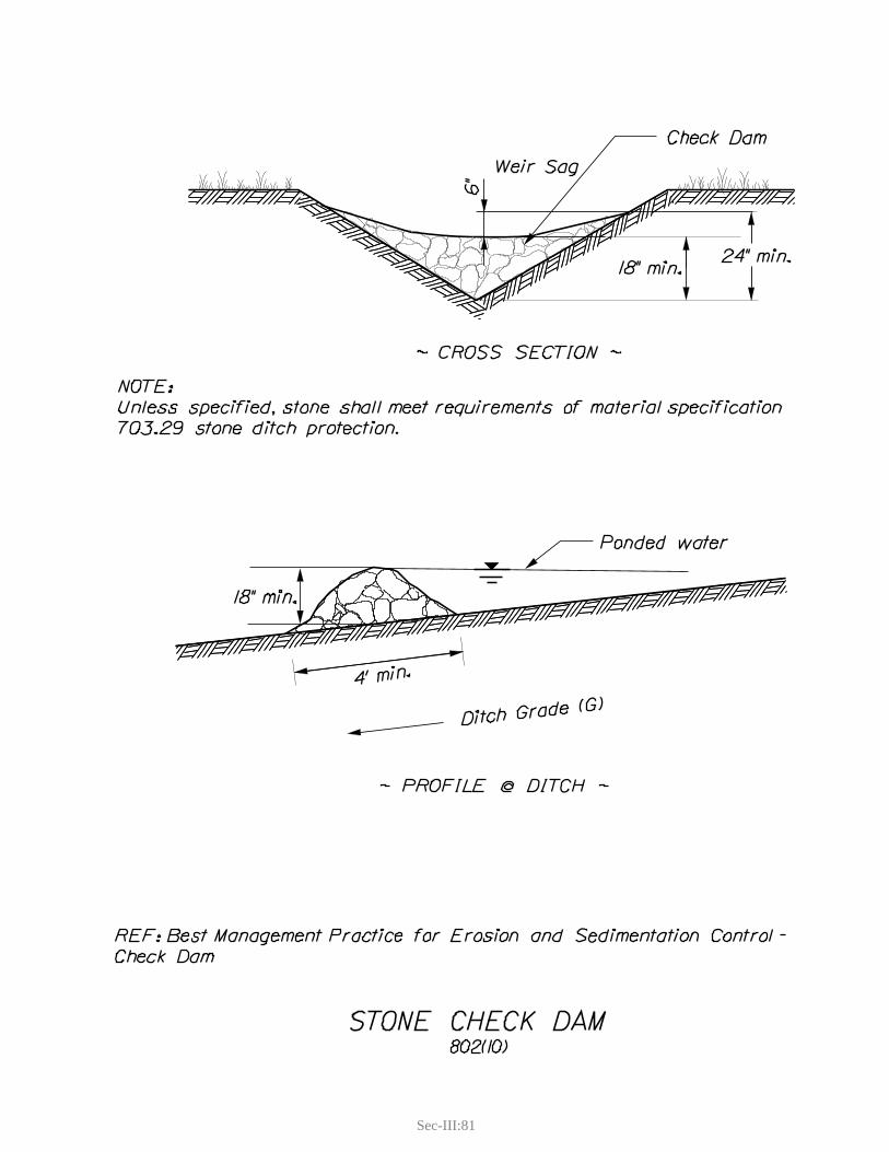
Sec-III:81

Sec-III:83
2. SEDIMENT TRAPS
Definition and PurposeSediment traps are small basins designed to settle out sediments from concentrated stormwater runoff (typically ditch flow). Sediment traps are generally small excavated depressions, but can also be constructed by damming a drainage swale; see Check Dams. Sediment traps act to slow the velocity of water thereby decreasing its energy and causing sediment (and attached pollutants) to settle out of suspension. Sediment traps are generally considered to be the primary treatment to remove sand. Additional measures may be necessary to trap lighter silt and clay particles (i.e., detention basins, wet ponds, and filter strips).
Appropriate Applications
During construction, as a temporary measure to support other erosion and sedimentation controls funtil final stabilization has been achieved.As a permanent measure to remove winter sand or other coarse sediments from roadway fdrainage systems.For treatment of ditch drainage prior to discharge to a water resource. fAs a pretreatment measure for other BMPs such as Road Ditch Turnouts, Level Spreaders, Filter fStrips, etc.
Limitations
Proper sizing may be limited by Right of Way restrictions. fContributing drainage area should be less than 5 acres. Larger drainage areas require detailed fengineering design.Will not effectively treat silts and clays. fFrequent inspection and removal of accumulated sediments is required. fNot for use within streams. f
Standards and SpecificationsRefer to Standard Detail Drawing. fSediment traps are best located in flatter areas to get the maximum storage benefit from the fterrain. Provide convenient equipment access to enable proper maintenance. fThe outlet must discharge into a stable, well-vegetated area or into a stable drainage way. fInstall outlet protection measures to prevent scouring (typically a riprap apron). fSediment trap dimensions should be oriented to maximize the distance that water travels through fthem. Minimum length to width ratio of the trap is 2:1. Baffles can be constructed within the trap to maximize the travel distance. Minimum depth is 2 feet. f
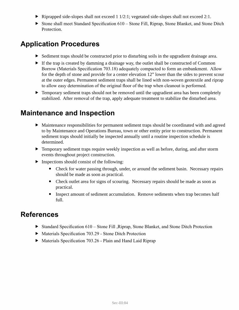
Sec-III:84
Riprapped side-slopes shall not exceed 1 1/2:1; vegetated side-slopes shall not exceed 2:1. fStone shall meet Standard Specification 610 – Stone Fill, Riprap, Stone Blanket, and Stone Ditch fProtection.
Application Procedures
Sediment traps should be constructed prior to disturbing soils in the upgradient drainage area. fIf the trap is created by damming a drainage way, the outlet shall be constructed of Common fBorrow (Materials Specification 703.18) adequately compacted to form an embankment. Allow for the depth of stone and provide for a center elevation 12” lower than the sides to prevent scour at the outer edges. Permanent sediment traps shall be lined with non-woven geotextile and riprap to allow easy determination of the original floor of the trap when cleanout is performed.Temporary sediment traps should not be removed until the upgradient area has been completely fstabilized. After removal of the trap, apply adequate treatment to stabilize the disturbed area.
Maintenance and Inspection
Maintenance responsibilities for permanent sediment traps should be coordinated with and agreed fto by Maintenance and Operations Bureau, town or other entity prior to construction. Permanent sediment traps should initially be inspected annually until a routine inspection schedule is determined.Temporary sediment traps require weekly inspection as well as before, during, and after storm fevents throughout project construction. Inspections should consist of the following: f
Check for water passing through, under, or around the sediment basin. Necessary repairs yshould be made as soon as practical.Check outlet area for signs of scouring. Necessary repairs should be made as soon as ypractical. Inspect amount of sediment accumulation. Remove sediments when trap becomes half yfull.
References
Standard Specification 610 – Stone Fill ,Riprap, Stone Blanket, and Stone Ditch Protection fMaterials Specification 703.29 - Stone Ditch Protection fMaterials Specification 703.26 - Plain and Hand Laid Riprap f
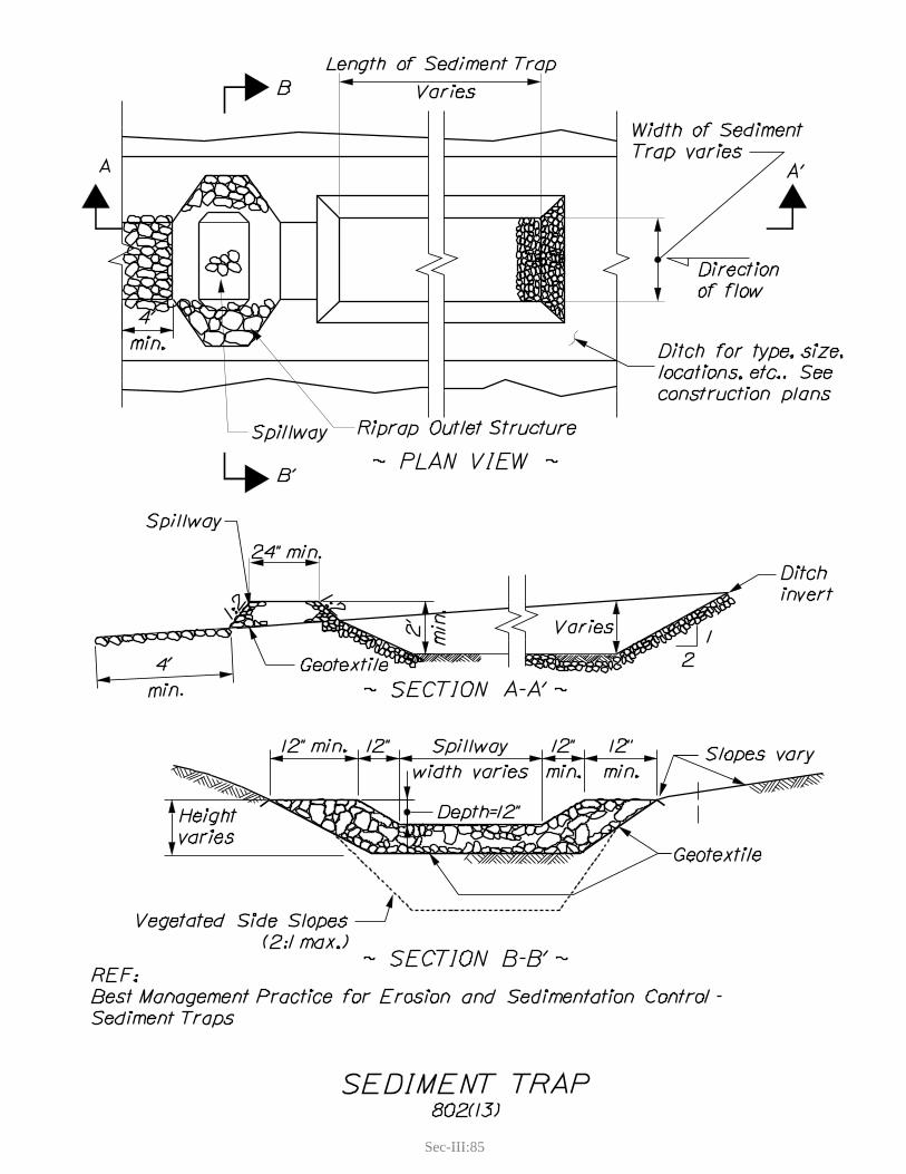
Sec-III:85

Sec-III:87
3. STORM DRAIN INLET PROTECTION
Definition and PurposeStorm drain inlet protection is a category of temporary BMPs that provide sedimentation control at inlets to closed storm drainage systems (catch basins) during construction activities. Closed drainage systems often discharge directly into or adjacent to wetlands and/or waterbodies, therefore storm drain inlet protection is often the last opportunity to protect these resources.
There are two basic types of storm drain inlet protection: perimeter protection and in-structure protection.
Perimeter storm drain inlet protection is a semi-permeable barrier placed around the entire perimeter of a storm drain inlet. The barrier slows the concentrated stormwater runoff, thereby decreasing its energy and causing sediment to settle before discharging to the storm drain.
In-structure storm drain inlet protection consists of membranes that are suspended within individual catch basin structures. Membranes typically consist of woven geotextile that filters most sands and gravels, but do not filter silts and clays. Once full of sediment they can be lifted out of the catch basin with earth moving equipment. In-structure storm drain inlet protection devices are typically manufactured devices.
Appropriate Applications
Temporary sedimentation control around existing closed drainage inlets receiving runoff from fupgradient construction, until stabilization of upgradient areas. Temporary sedimentation control during construction of new closed drainage systems, until fsurface paving is complete.
Limitations
Generally only effective for small drainage areas (1 acre or less). fOnly use at inlets where ponding will not endanger traffic or flood onto erodible areas. fFrequent maintenance is required for all methods of storm drain inlet protection. fWithout adequate reinforcement, some filters could collapse, potentially blocking the inlet and fcausing flooding.Storm drain inlet protection may not be suitable for use along long, interconnected road segments fwith closed drainage because they will pond water on the road.
Standards and SpecificationsPerimeter storm drain inlet protection may consist of any of the following four options. Other alternatives are acceptable with the approval of the Resident and/or SWQU staff.
Stone Berm fRefer to Standard Detail Drawing. y
Sec-III:88
Continuous berm of clean stone aggregate placed around the entire perimeter of storm ydrain inlet. MaineDOT Materials Specification 703.24 – Stone for French Drains or other clean gravel as approved by the Resident.Place on pavement or bare ground. Geotextile fabric should be placed over inlet grate yand under the stone extending a minimum of 12 inches beyond edge of grate.Berm height should be 12 inches and top of berm should be level all around. y
Sandbag Berm fContinuous berm of stone or sand filled sandbags placed around entire perimeter of storm ydrain inlet.The bags are butted together so that there is no bypass through the bags. yPlace on pavement or bare ground. yMaximum recommended height is 12 inches. y
Silt Fence fRefer to Standard Detail Drawing. yConsists of standard silt fence with some form of wood frame bracing. yThe bottom flap of the silt fence must be buried in a trench or covered with a lip of ycrushed stone to prevent short circuiting. Use silt fence from a continuous roll to avoid joints in the filter; see y Silt Fence (SR-SC).Wood frame shall be constructed from 2 x 4 lumber. yMinimum fence height is 15 inches, maximum height is 20 inches. y
Continuous Containment Berm fCommercial products are available but must be approved by the Resident before use. y
In-Structure Storm Drain Inlet Protections
MaineDOT does not endorse a particular manufacturer’s product. fUse of these products must be approved by the Resident. fInstall according to manufacturer’s specifications. f
Application Procedures
Stone Berm fLay geotextile fabric around inlet if on bare ground (not necessary for paved surfaces. yConstruct a continuous stone berm around the inlet (over geotextile fabric if on bare yground).Build berm to approximate height of 1 foot and level top of berm so that there is 0% ygrade all the way around.

Sec-III:89
Sandbag Berm fPartially fill bags with stone or sand. yPlace bags around inlet and butt bags together such that no gaps are evident between ybags.If a second layer of bags is added, stagger placement of the bags so that they cover the yends of the bags in the first layer.
Silt Fence fDrive stakes a minimum of 8 inches into the ground and a maximum of 3 feet apart yaround the perimeter of the inlet.Build a frame that connects the tops of the stakes together. yExcavate a trench approximately 6 inches wide and 6 inches deep around the outside yperimeter of the stakes.If using a wire screen backing, attach backing to the stakes. yAttach silt fence to the stakes such that 1 foot of fabric extends into the trench. yOverlap silt fence at the corner a minimum of 6 inches yBackfill and compact trench material over the silt fence fabric. yIf using crushed stone, place stone along the base of the silt fence. y
In-Structure Storm Drain Inlet Protections:
Follow the manufacturer’s installation guidelines. f
Maintenance and Inspections
The Contractor should inspect storm drain inlet protection weekly and prior to, during, and fafter storm events to check for damage and sediment accumulation. Any damage should be repaired immediately and sediment should be removed when it reaches half the height of the barrier. Stone that has become plugged with sediment should be replaced with clean stone. See manufacturer’s maintenance guidance for maintaining manufactured storm drain inlet protection.Storm drain inlet protection shall be removed when the contributing drainage area has been fproperly stabilized. Any disturbance caused by storm drain inlet protection installation and removal will have to be stabilized. All catch basins and associated drainage pipes must be cleaned at the end of construction and fafter the site has been fully stabilized.
References
Materials Specification 703.24 – Stone for French Drains fStandard Specification 620 – Geotextiles f
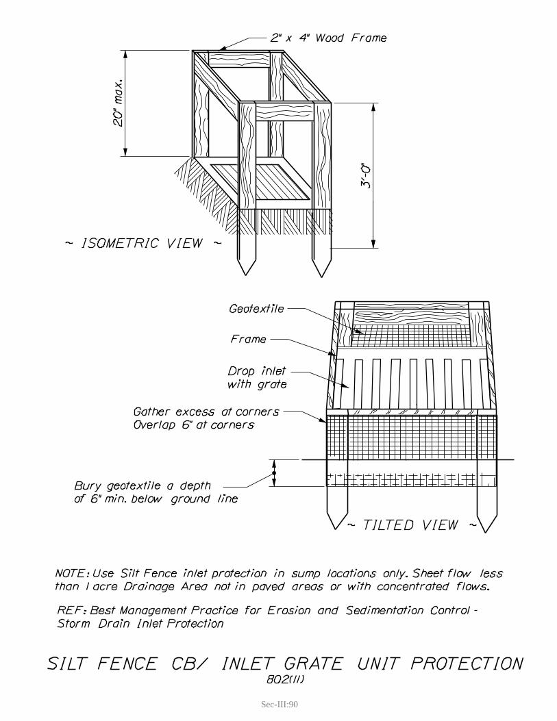
Sec-III:90
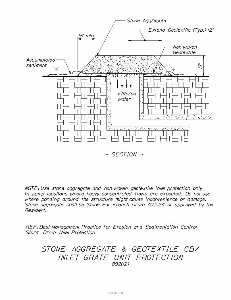
Sec-III:91

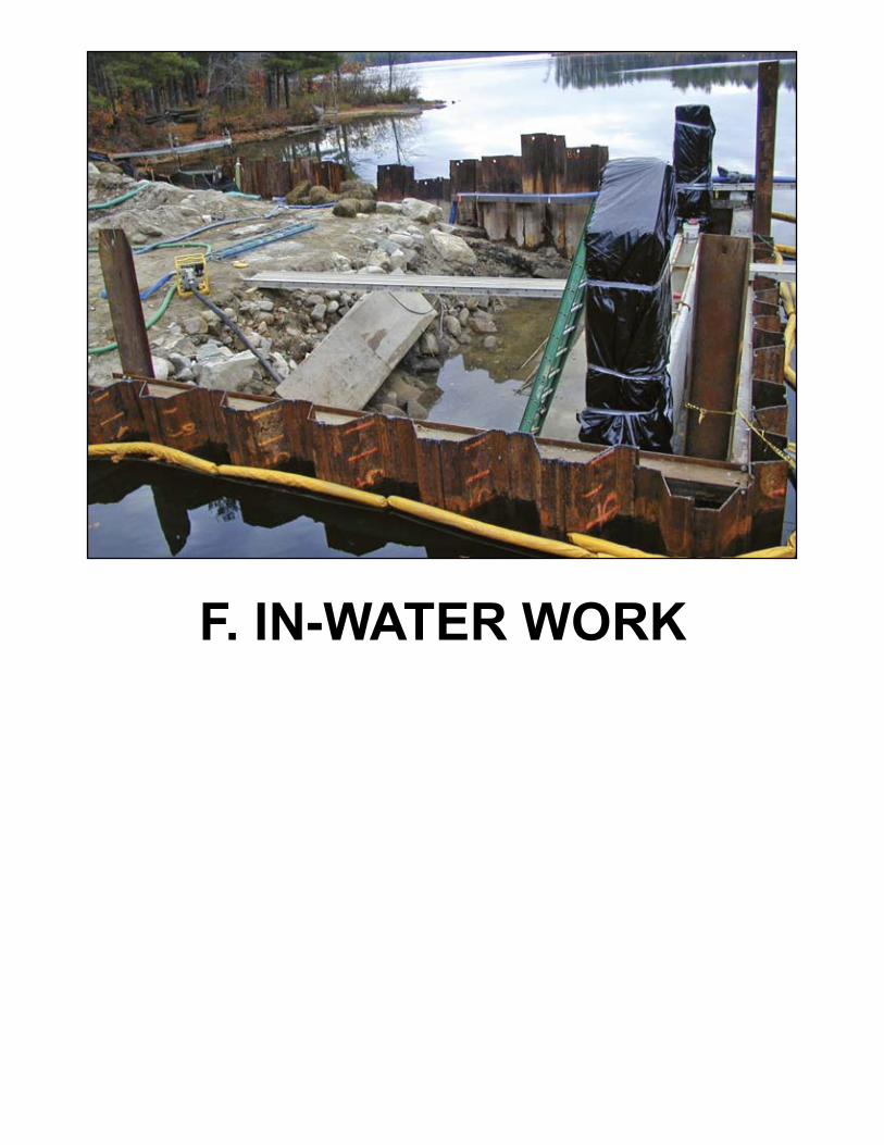
F. IN-WATER WORK


Sec-III:95
F. IN-WATER WORKA large proportion of MaineDOT projects involve culvert and bridge replacement and repair. Working in and adjacent to a water resource increases the risk for a discharge of sediment. Site conditions vary greatly in the type of waterbody and the scope of the construction project. These BMPs provide guidance and some basic standards, but minimizing that risk also requires knowledge of the flow characteristics of the waterbody and seepage characteristics of the soils in the work area, along with good planning, experience, and ingenuity. When the waterbody is a stream there may be a need for maintaining vehicle traffic on the road during construction and therefore a temporary stream crossing. It is a standard permit requirement that, for streams, flow must be maintained into the downstream channel.
These practices are not stand alone. They are used in combinations, depending on the scope of the project and the water body involved. They include:
Floating Turbidity Curtain fTemporary Stream Crossing fTemporary Stream Diversion fCofferdams fDewatering fTemporary Sediment Basins fFilter Bags f

Sec-III:97
1. FLOATING TURBIDITY CURTAIN
Definition and PurposeFloating turbidity curtains (a.k.a. silt curtains, silt boom, sediment curtain) are a temporary in-water sediment barrier consisting of a continuous geotextile fabric curtain suspended from a flotation device on the water surface and held in a vertical position by ballast weight at the bottom.
Appropriate Applications
In-water construction activities such as dredging, bank stabilization, in-water fill. fWhere earth disturbance is adjacent to the waterbody and land based sediment controls can not fbe installed.Relatively shallow and calm water bodies. f
Limitations
Not for use where water velocities exceed 1.5 feet per second. Some commercial products are fdesigned for velocities up to 6 feet per second, but use of these products must be approved by the Resident. Not for use in areas experiencing significant wave action. f
Standards and SpecificationsFollow Manufacturer’s Guidelines and Specifications. fThe curtain should fully isolate the construction area. fBallast must consist of a continuous weight (i.e., chain or cable) that is incorporated into the fcurtain to provide a continuous seal with the bottom of the resource. The curtain shall be suspended in the water column in a vertical plane to the extent possible. fThis will prevent sediments from accumulating on the curtain, which would cause re-disturbance when the curtain is removed.The curtain should be left in place for at least 24 hours after completion of disturbance activities fto allow for settling of sediments.
Application Procedures
If available, follow the manufacturer’s installation procedures. fShoreline activities should be isolated by wrapping both ends of the curtain onto shore. In-water factivities require a fully enclosed perimeter where ends of the curtain overlap. Intermediate anchors shall be installed in accordance with manufacturer’s specifications.All anchors must be set in place, buoy marked, and tested before the curtain is deployed. fTerminal end anchors (e.g., trees, steel posts, or poured concrete dead-men) should be located on fshore and easily accessible.
Sec-III:98
Unfurl the turbidity curtain in accordance with manufacturer’s recommendations. fThe staging area must be cleared of sharp objects, debris, brush or tree roots or anything else that fmay snag the curtain as it is being moved into the water.Move the unfurled floating turbidity curtain into position. fSecure the anchor lines to the top load cable. fRelease the furling lines to let the curtain reach its working depth. fAfter the completion of work, re-furl the boom, disconnect the anchor lines and remove curtain. f
Maintenance and Inspections
Check for proper function when sedimentation is occurring. Sediment should be fully contained fby the floating turbidity curtain. Signs of leakage or bypass should be assessed and addressed immediately. Inspect the floating turbidity curtain weekly, on windy days, and before, during, and after storm fevents. Ensure that the connections between curtain sections and the connections to the anchor lines are secure.Keep any debris that might damage the fabric clear from the curtain. fIf the curtain is damaged while construction is ongoing, it should be repaired in-place in order to fmaintain its function. After each use, the curtain should be spread out on a flat surface, cleaned thoroughly by brushing fwith water and detergent, rinsed and allowed to dry.Patch tears and abrasions using special cements and fabric obtainable from the manufacturer. f
References
Manufacturer’s Guidelines and Specifications f
Sec-III:99
2. TEMPORARY STREAM CROSSING
Definition and PurposeA temporary stream crossing is a temporary structure in or over a stream to provide safe, minimal disturbance access for construction equipment or the traveling public. The structure is either a bridge or a culvert and will be removed upon completion of project construction. The purpose is to prevent damage to the waterway, blocking fish passage, and tracking sediment and other pollutants into the water.
Appropriate Applications
On any water body where construction equipment or the traveling public need to travel over the fwater body during project construction.
Limitations
Temporary structures may be subject to permitting requirements and in-water work windows f(contact the MaineDOT ENV Office).Installation of a temporary crossing may include in-water work and require installation of fcofferdams, temporary stream diversions, and cofferdam sedimentation basins; see each specific BMP.
Standards and SpecificationsThe approach fills shall be placed on a geotextile fabric in order to minimize disturbance of the fexisting vegetation and facilitate removal. Temporary crossing in use for less than ten days shall be sized for the existing observed stream fflow. Temporary crossing in use for more than ten days shall be sized for the following criteria: f
In use between June 1 and September 15 shall be sized for a minimum 50% of the 2 year ystorm event.In use prior to June 1 or after September 15 shall be sized for a minimum flow from the 2 yyear storm event.Intended to remain in place over the winter shall be sized for minimum flow from the 5 yyear storm event. A temporary bridge shall be sized for minimum flow from the 10 year storm event. y
Design provisions shall be made for flows exceeding the designed flows without a sediment fdischarge to the water body, typically a low area in the approach road that is armored from overtopping flows and protecting the temporary structure from failure. If the temporary crossing is a culvert it may be required to provide fish passage. Consult with fthe MaineDOT Environmental Office for assistance. Clearing adjacent to water bodies shall be the minimum necessary to install the temporary fcrossing. Wherever possible, roots shall be left in place to regenerate.
Sec-III:100
Water runoff from the approaches shall be diverted away from the temporary crossing and shall fnot be allowed to run down or along the approach fills. Temporary crossing designs shall be submitted to the Resident or, in the case of Maintenance and fOperation projects, the Region Engineer for approval. Refer to Standard Specification 510 - Special Detours. f
Application Procedures
Install cofferdams and stream diversion as necessary for in-water work. Install other BMPs as fneeded.Place approach fills on geotextile or mats. fStabilize side slopes of approach fills. fInstall temporary culvert or bridge in accordance with MaineDOT Bridge Design Guide. fStabilize inlets/outlets of structure. fProceed with the project without delays and remove temporary culvert or bridge and approaches fas soon as possible.Stabilize disturbed soils in the area. f
Maintenance and Inspections
All temporary crossings shall be inspected at least once a week and before, during, and after fstorm events to ensure that the structure is not damaged, that sediment is not entering the waterbody, and that there are no obstructions to flow or fish passage (if required).Blockage by debris in the channel which could contribute to flooding shall be removed. f
References
Standard Specification 510 – Special Detours f
Sec-III:101
3. TEMPORARY STREAM DIVERSION
Definition and PurposeThis practice diverts stream flow around an in-water construction site and maintains flow from upstream to downstream. It is typically used with the other BMPs in this section to prevent erosion and sediment discharge to the water resource. Temporary stream diversions incorporate cofferdams with one of the following means to divert stream flow:
Pump diversion fPipe diversion fPlastic sheet-lined open channel f
Appropriate Applications
General fIn-stream work activities where water flow must be maintained. y
Pump Diversions fSmall streams with flow rates that are less than approximately 5 cubic feet per second. yShort project duration; typically one-day construction projects. y
Pipe Diversions fSmall streams with flow rates that are less than approximately 5 cubic feet per second. yWhere replacement structure is on a different alignment the existing structure (pipe) may ybe used.For slip-lined and invert lined projects where the road surface remains undisturbed and ytraffic flow is retained.
Open Channel Diversions fLarge streams and small rivers where neither pump nor pipe diversions are practical and yroad is closed to traffic for duration of use.Where diversion will be in place for long periods and higher storm flows are anticipated. y
Limitations
General fIn-stream work is subject to permitting requirements and work windows; proper permits ymust be in place.Temporary stream diversion alternatives are typically designed to pass monthly mean low yflows for the duration of their use and not for storm flows. Measures for overtopping and work area flooding must be in place.
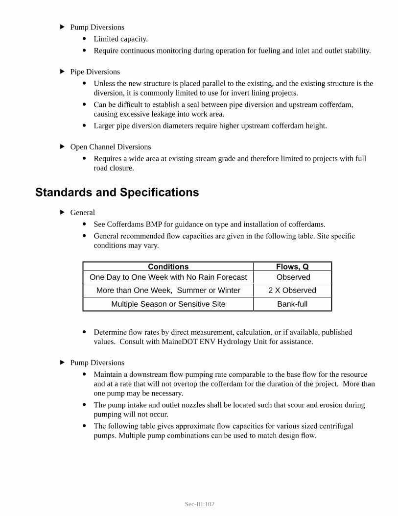
Sec-III:102
Pump Diversions fLimited capacity. yRequire continuous monitoring during operation for fueling and inlet and outlet stability. y
Pipe Diversions fUnless the new structure is placed parallel to the existing, and the existing structure is the ydiversion, it is commonly limited to use for invert lining projects. Can be difficult to establish a seal between pipe diversion and upstream cofferdam, ycausing excessive leakage into work area. Larger pipe diversion diameters require higher upstream cofferdam height. y
Open Channel Diversions fRequires a wide area at existing stream grade and therefore limited to projects with full yroad closure.
Standards and SpecificationsGeneral f
See Cofferdams BMP for guidance on type and installation of cofferdams. yGeneral recommended flow capacities are given in the following table. Site specific yconditions may vary.
Determine flow rates by direct measurement, calculation, or if available, published yvalues. Consult with MaineDOT ENV Hydrology Unit for assistance.
Pump Diversions fMaintain a downstream flow pumping rate comparable to the base flow for the resource yand at a rate that will not overtop the cofferdam for the duration of the project. More than one pump may be necessary.The pump intake and outlet nozzles shall be located such that scour and erosion during ypumping will not occur.The following table gives approximate flow capacities for various sized centrifugal ypumps. Multiple pump combinations can be used to match design flow.
Conditions Flows, QOne Day to One Week with No Rain Forecast Observed
More than One Week, Summer or Winter 2 X Observed
Multiple Season or Sensitive Site Bank-full
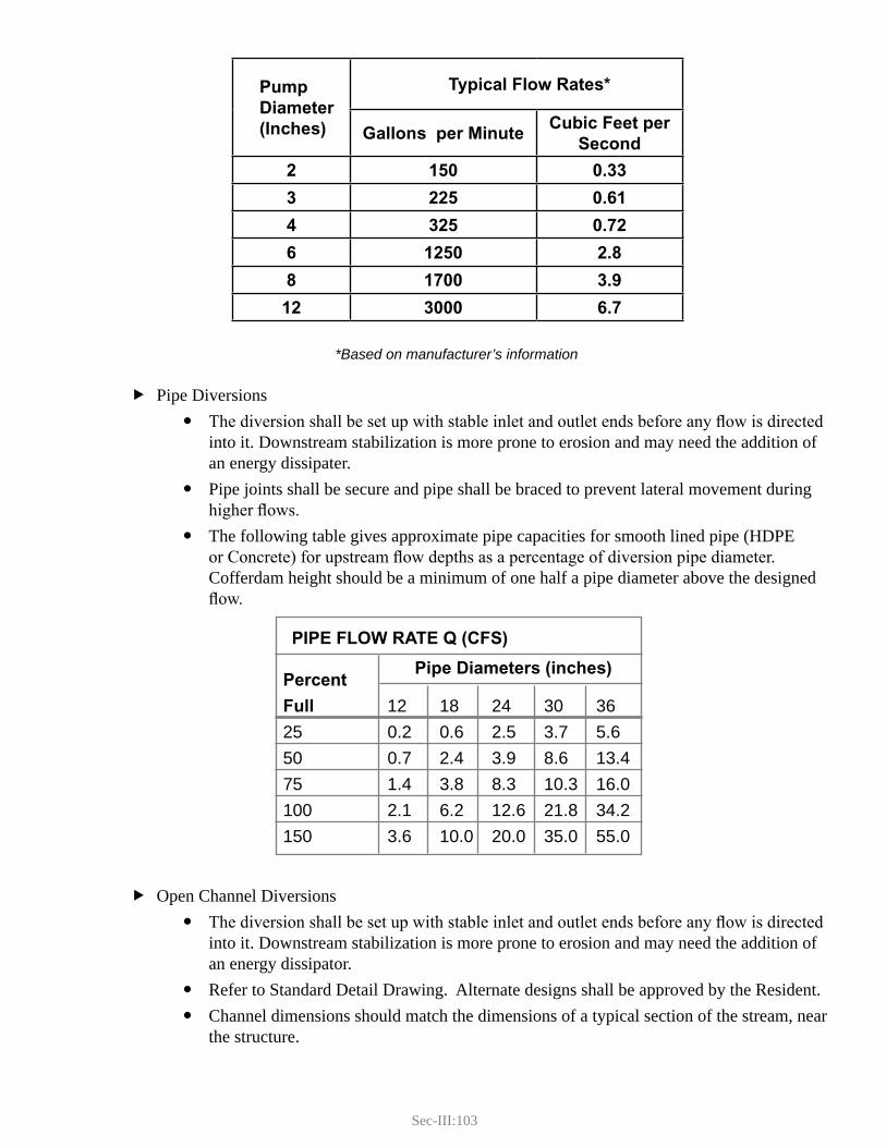
Sec-III:103
*Based on manufacturer’s information
Pipe Diversions fThe diversion shall be set up with stable inlet and outlet ends before any flow is directed yinto it. Downstream stabilization is more prone to erosion and may need the addition of an energy dissipater.Pipe joints shall be secure and pipe shall be braced to prevent lateral movement during yhigher flows.The following table gives approximate pipe capacities for smooth lined pipe (HDPE yor Concrete) for upstream flow depths as a percentage of diversion pipe diameter. Cofferdam height should be a minimum of one half a pipe diameter above the designed flow.
Open Channel Diversions fThe diversion shall be set up with stable inlet and outlet ends before any flow is directed yinto it. Downstream stabilization is more prone to erosion and may need the addition of an energy dissipator.Refer to Standard Detail Drawing. Alternate designs shall be approved by the Resident. yChannel dimensions should match the dimensions of a typical section of the stream, near ythe structure.
PIPE FLOW RATE Q (CFS)
Percent
Full 12 18 24 30 3625 0.2 0.6 2.5 3.7 5.650 0.7 2.4 3.9 8.6 13.475 1.4 3.8 8.3 10.3 16.0100 2.1 6.2 12.6 21.8 34.2150 3.6 10.0 20.0 35.0 55.0
Pipe Diameters (inches)
Pump Diameter (Inches)
Typical Flow Rates*
Gallons per MinuteCubic Feet per
Second
2 150 0.33
3 225 0.614 325 0.72
6 1250 2.8
8 1700 3.9
12 3000 6.7
Sec-III:104
Lining materials for the open channel diversion shall consist of a plastic liner with a yminimum thickness of 4 mil. It shall be placed in one long continuous piece to the extent possible. If multiple sections are used, the upstream section shall be shingled over the downstream section with an overlap of at least 2 feet. Channel liner cross-section shall not have any longitudinal seams. The liner shall be ykeyed-in or anchored above the flow line along longitudinal edges. Inlet and outlet edges of the liner should also be anchored. Additional anchors may be needed within the trench and at overlaps.
Application Procedures
The variability in project scope and site conditions will determine which type of temporary stream diversion will be used. The sequence of activities is critical to minimizing stream impacts. The layout should be planned considering the following recommendations:
Install the temporary diversion in a manner that does not produce a discharge to the resource. fThis may include installing a separate cofferdam from the main channel cofferdam. Install a stable outlet for the intended flows. fBegin diversion, i.e. start pump, breach temporary cofferdam, submerge pipe inlet. fInstall project cofferdam. This is usually done at the same time as the previous step. fMaintain diversion, dewater within cofferdam and complete project; see f Temporary Sediment Basin BMP.Once project is complete, breach project cofferdam and cease temporary diversion from the fupstream end. Remove temporary diversion and stabilize site. f
Maintenance and Inspections
The temporary stream diversion is a high maintenance item because of the potential for flooding from upstream runoff, leakage, or structural failure. It shall be monitored routinely during active construction and daily during weekends. Weather reports shall be checked daily and accommodations made in preparation for storm events. Preparations may include obtaining and readying additional pumps, raising the cofferdam height, stabilizing the work area, and removing debris from the diversion pipe. Remove the diversion immediately upon completion of in-water work.
References
Manufacturer’s Guidelines and Specifications f
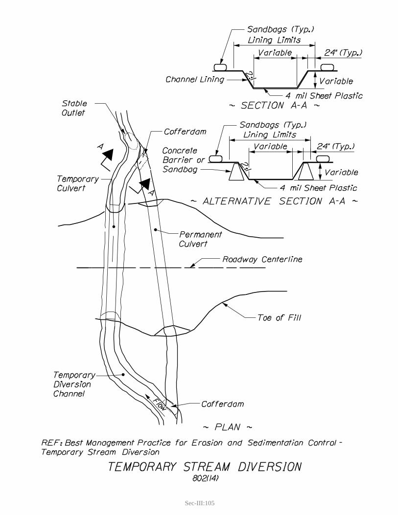
Sec-III:105

Sec-III:107
4. COFFERDAMS
Definition and PurposeCofferdams are watertight temporary structures enclosing a part of a waterbody to enable it to be pumped dry for construction purposes. Cofferdams are typically comprised of sandbags, concrete barriers, sheet piles, or manufactured devices. Isolation and dewatering provides a dry working area and is often necessary to prevent adverse environmental impacts from the construction activities.
Appropriate Applications
In all water bodies to isolate the work area from the water resource. fProvide a dry construction work area. fUse with other in-water work BMPs. f
Limitations
In stream and river systems, high flows can cause overtopping or failure of cofferdams. fCofferdams that will be in place for an extended duration should be designed to accommodate the likelihood of flooding.Cofferdamming a stream channel requires that provisions be made to maintain stream flow faround work site; see Temporary Stream Diversion.The permeability of the water body substrate needs to be considered when selecting the type of fcofferdam to be used.Cofferdams are rarely completely watertight and will require continued maintenance dewatering; fsee Dewatering.
Standards and SpecificationsThere are three primary design criteria for cofferdams:
Minimal seepage through, under, and around the cofferdam to the extent practical. fStructural stability and integrity of the cofferdam. fSufficient freeboard to accommodate reasonably expected fluctuations in water levels. f
All cofferdams shall conform to applicable standards specified in MaineDOT Standard Specification 511 – Cofferdams.
Sandbag Cofferdams fSandbag Material: Sandbag material shall be polypropylene, polyethylene, or polyamide ywoven fabric, minimum unit weight of four ounces per square yard, mullen burst strength exceeding 300 psi in conformance with the requirements in ASTM designation D3786, and ultraviolet stability exceeding 70 percent in conformance with the requirements in ASTM designation D4355. Use of burlap is not acceptable.

Sec-III:108
Sandbag Size: Each sand-filled bag shall have a length of 18 inches, width of 12 inches, ythickness of 3 inches, and weight of approximately 33 lbs. Bag dimensions are nominal, and may vary based on locally available materials. Alternative bag sizes shall be submitted to the Resident for approval prior to use.Grade of Sand: All sandbag material shall be coarse sand, free from deleterious ymaterials. Plastic Sheeting: Plastic sheeting should be utilized to minimize seepage through the ycofferdam. Sheeting should be anchored under the base of the cofferdam and wrapped up and over the top of the cofferdam. Where there is a unacceptable level of seepage through the substrate the plastic sheeting should be extended upstream along the bottom of the water body perpendicular to the cofferdam.Height of Dam: Up to 3 feet, measured from the existing streambed to the top of yberm. Sandbags will be placed to create a low spot within the top of the berm to direct overtopping flood flow.
Concrete Barrier Cofferdams fCaution: If concrete barriers are used, they must have a firm foundation or additional ysupport against overturning. This analysis is the responsibility of the contractor.Concrete barriers (Jersey barriers) should be machine placed on the channel bottom and ycoupled together according to manufacturer’s specifications.Plastic Sheeting: Plastic sheeting is required for the concrete barrier cofferdam to yfunction. Sheeting should be anchored under the base of the cofferdam and wrapped up and over the top of the cofferdam and extended upstream along the bottom of the water body perpendicular to the cofferdam. The distance that it is extended upstream depends on the permeability of the substrate.Ancillary Sandbags: Ancillary sandbags (meeting specifications in section above) should ybe used in situations where it is difficult to obtain a good bottom seal and as additional structural support against overturning.Height of Dam: Standard height of concrete barriers is 32 inches measured from the yexisting streambed to the top of barrier.
Other Cofferdam Types fOther types of cofferdams shall be approved by the project Resident on a case by case ybasis. Typical alternatives include: Sheet Piles, Large Sandbags, and Proprietary/Manufactured devices.
Application Procedures
Stream flow shall be maintained at a rate similar to natural conditions. fTiming of the installation of cofferdams is critical to minimize impacts on fish and other aquatic flife. Cofferdams cannot be used across a streambed during times when fish passage is an issue. In-stream work windows are defined by the Environmental Office for most in-water work activities.

Sec-III:109
Because the potential for washout is high, the cofferdam must be carefully monitored, and must fnot be left unattended for any 24-hour period. Weather reports must be monitored. If a storm event is expected, the site must be stabilized in preparation for it.Turbid water within the cofferdam should be pumped into a temporary sedimentation basin or ftank truck, and should not be allowed to discharge directly to any protected natural resource; see Temporary Sedimentation Basin.Dual cofferdams (upstream and downstream) are generally necessary in situations that require fblocking off the entire stream channel.Refer to f Dewatering BMP for guidance on dewatering activities.
The sequence of activities is critical to minimizing environmental impacts. In general, the upstream cofferdam is installed first, then the downstream cofferdam. After completion of the work, the sequence is reversed and the downstream cofferdam is removed before the upstream.
Maintenance and Inspections
Inspect daily throughout use. fRepair and reposition any damaged or displaced cofferdam components. fRepair washouts or other damage as needed. fSandbags should be removed by hand to prevent breakage and unnecessary disturbance of the fstreambed.When using an upstream and downstream dam, remove the downstream dam first. f
References
Standard Specification 511 - Cofferdams f

Sec-III:111
5. DEWATERING
Definition and PurposeDewatering is the removal of water from within a contained work area so that construction work may be accomplished. Dewatering is a component of a suite of in-water work BMPs including: cofferdams, temporary sedimentation basins, and geotextile filter bags.
This practice does not address the dewatering of water contaminated from hazardous wastes or fuel spills. Contact the MaineDOT ENV Hazardous Waste Unit for procedures for investigation, identification, and handling of these contaminants.
Appropriate Applications
In-water work within cofferdams. fTrenching. fMaintenance or repair of stormwater drainage systems. f
Limitations
The capacity of pumping systems and site specific volumes and flow rates required. f
Standards and SpecificationsContaminated water shall not be discharged directly to the resource. It shall be treated by the use fof a temporary sedimentation control device. This is typically a temporary sedimentation basin, geotextile filter bags, direct discharge to a tank truck, or other methods approved by the Resident. A direct discharge of clean water from within a cofferdam to the resource must be approved by fthe Surface Water Quality Unit. Minimize the quantity of impacted water that requires treatment by: f
Minimizing the volume of the containment area to the extent practical ySeal the containment area to the extent practical to prevent seepage from water body; see yCofferdam.Isolate clean water seepage by constructing sumps whereby clean water can be pumped yback into the resource. Clean water sumps consist of a recessed pump intake area backfilled with clean crushed stone to prevent turbidity caused by suction at the pump intake. The pump intake should be buffered on all sides by a minimum of 6” of clean stone. Pump sizing should be based on the seepage rate, as it is preferable to maintain a steady state condition.Where approved, pump clean drawdown water overboard. y

Sec-III:112
Pumping Equipment: fMultiple pumps may be necessary to pump clean and dirty water separately. Centrifugal ypumps are recommended for most applications. Positive displacement pumps are recommended when water is laden with solids. Water Volume – A large pump may be desirable to reduce downtime associated with ywaiting for a site to dewater. Typically smaller pumps can be used for maintenance dewatering, provided seepage is not excessive.Maintenance Pumping – Cofferdams seepage rates may vary widely from site to site and ywill dictate the size of pump necessary.Elevation of pump above the water surface and distance of discharge line will greatly yaffect pumping capacities. Consult with a professional engineer when appropriate.
Prevent localized erosion associated with the pump intake and discharge points. It may be fnecessary to construct a stabilized pad to prevent this type of localized disturbance from occurring. Pads can be constructed from rocks, plywood, geosynthetic fabric, plastic sheeting, etc.
Application Procedures
If cofferdams, temporary sedimentation basins, or geotextile filter bags are used refer to the fapplicable BMP in this section.Initial dewatering is a critical procedure when various assessments should be made: f
Water Quality – Clean water may be discharged directly back into the resource without ybeing treated. Contaminated water shall be discharged into a temporary sedimentation device.Seepage – Evaluate the degree of cofferdam seepage and determine whether further yseepage control (sealing) and/or pump capacity is needed.Clean Water Sumps – Once drawdown is nearly complete, assess the bottom conditions yand seepage conditions to determine whether clean water sumps are necessary or practical. Proper function of a clean water sump is based on the quality of water at the discharge. There should be no observable negative impact to the resource.Initial Bottom Preparations – Some turbidity is likely to occur while some of the initial ybottom preparations are being installed (i.e., sumps and/or stable extraction pads). Any contaminated water extracted during this time should be discharged to the temporary sedimentation device.
Maintain pump operation throughout construction activity. fDewatered area should be reflooded gradually upon completion of in-water work, to prevent fsediments from resuspending during cofferdam breaching; see Cofferdam.
Sec-III:113
Maintenance and Inspection
The following items should be inspected and maintained continually during the course of construction operations within a dewatered area.
Cofferdam Integrity – Observe any increases in seepage rate. If changes are observed, locate and frepair leaks.Water Quality – Observe any clean water discharges to the resource, to ensure that they remain fclean. If they are not, redistribute discharges as appropriate and correct any deficiencies.Temporary Sedimentation Devices – Verify proper function of the temporary sedimentation fdevices. Conduct cleaning and/or installation of additional capacity as necessary.
References
Pump manufacturer’s specifications f

Sec-III:115
6. TemPoRARy SeDimenT bASin
Definition and Purpose Temporary sediment basins consist of designated impoundment areas that are used to treat contaminated (sediment, high pH) water pumped from a dewatering process. Temporary sediment basins provide water treatment through the following mechanisms:
Reduction in velocity of the discharge flow providing adequate time for sediment to settle out. fFiltration of coarse sediment through a permeable non-woven geotextile. fSheet flow discharge from the temporary sedimentation basin through a vegetated area removes fan additional portion of finer sediments.Potential infiltration into the ground, providing optimal treatment of all finer sediments. f
Temporary sediment basins can consist of above ground structures with permeable perimeter berms, natural depressions in the ground, or excavated depressions.
This practice only describes sedimentation basins constructed on ground. Basins constructed on barges or bridge decks for sheet pile cofferdam excavation and dewatering shall be designed by the contractor and approved by the Resident on a case-by-case basis.
Appropriate Applications
Work areas that require dewatering of contaminated water. f
Limitations
Shall not be located within wetlands or immediately adjacent to a water resource without pre- fapproval by the Surface Water Quality Unit. ROW restrictions may limit ability to use temporary sediment basins (may require temporary flandowner agreements).Difficult to determine balance of inflow rates with outflow capacity. Excessive inflow rates may frequire multiple basins. Geotextile fabric may clog with fine sediments and may require multiple basins. fFrozen ground conditions eliminate the potential for infiltration. fDifficult to design basin capacity for intended use because of seepage rates into cofferdam, fquality of water pumped, and treatment capacity of basin or downstream flow area. Adequate operation requires initial monitoring and may require trial and error adjustments.
Standards and SpecificationsLocation shall be approved by the Resident. fBasins shall have a minimum length to width ratio (from inlet to outlet) of 2:1. The longer the fbetter. Flow through the basin can be lengthened by installing baffles.

Sec-III:116
Basins shall be located in an upland area with a maximum ground slope of 2%. fTemporary basins should discharge to a stable and well-vegetated area (meadow grass or fforested) by sheet flow to provide further treatment. Downstream flow area shall have a maximum ground slope of 5% and a minimum distance from a wetland or waterbody of 25 linear feet. Basins may discharge to an existing drainage swale provided that the discharge has been adequately treated.Above-ground basins shall consist of Non-woven geotextile, meeting Materials Specification f722.03 - Erosion Control Geotextile, draped over a perimeter of haybales or concrete barriers, or enclosed perimeter of silt-fence buttressed by staked haybales. Natural depressions and/or excavated basins shall provide sufficient impounding capacity to fhandle flow from work area without overtopping. Low points may be blocked off with sandbags, wrapped haybales or similar temporary dams to prevent overtopping. If overtopping will occur, the dewatering process shall cease and measures taken to correct. fOptions include allowing water to draw down, constructing additional basins, or pumping to a tank truck for off-site disposal.
Application Procedures
For above ground basins using non-woven geotextile, clear area of woody vegetation that may fdamage fabric.Construct basin. fSet up and secure dewatering discharge hoses. fMonitor function of basin, including downstream flow. f
Maintenance and Inspections
Temporary sedimentation basins shall be monitored routinely (hourly) during usage. Frequency fdepends on the volume and quality of water being treated. Check for leakage, short-circuiting, and overtopping. Repairs should be made immediately. Inspect downstream filter area for concentrated flow and potential erosion of soil and forest duff flayer. Inspect location where water discharges to the resource for water quality. If the basin overtops during operation or if downstream filter area is not adequately performing, fstop pumping immediately and initiate mitigation from the following options:
Establish better cofferdam seals. yReinstall and, if needed, relocate additional basin(s). yClean out sediment (typically conducted when the basin is half full) and dispose of in an yapproved area or facility.Arrange for pumping to tank truck for off-site disposal. yUpon completion of the work, the basin shall be dismantled and the area shall be ypermanently stabilized with seed and mulch as needed.
References
Materials Specification 722.03 - Erosion Control Geotextile f
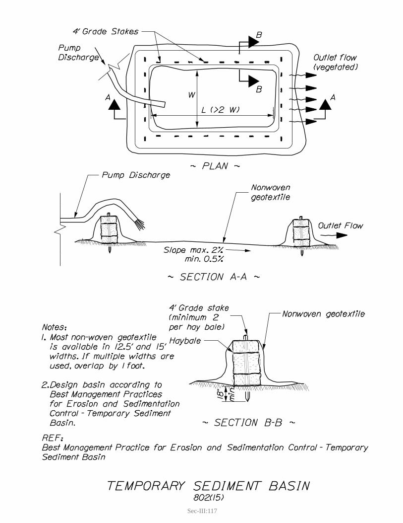
Sec-III:117


Sec-III:119
7. GEOTEXTILE FILTER BAGS
Definition and PurposeGeotextile filter bags are manufactured sedimentation devices consisting of a prefabricated sack made from a non-woven geotextile. They are designed to accept a pump discharge hose. Filter bags are used to treat contaminated water (sediment, pH) from a dewatering process. They provide water treatment through the following mechanisms:
Reduction in velocity of the discharge flow providing adequate time for sediment to settle out. fFiltration of coarse sediment through a permeable non-woven geotextile. fSheet flow discharge from filter bag through a vegetated area removes an additional portion of ffiner sediments.Potential infiltration into the ground, providing optimal treatment of all finer sediments. f
Appropriate Applications
Work areas that require dewatering of contaminated water. f
Limitations
Shall not be located within wetlands or immediately adjacent to a water resource without pre- fapproval by the Surface Water Quality Unit. ROW restrictions may limit ability to use temporary sedimentation basins (may require ftemporary landowner agreements).Difficult to determine balance of inflow rates with outflow capacity. Excessive inflow rates may frequire multiple filter bags or alternative measures. Frozen ground conditions eliminate the potential for infiltration. fFilter bags have a finite capacity for sediment removal and may be prone to plugging and failure fif these limitations are exceeded.
Standards and SpecificationsLocation shall be approved by the Resident. fThere are numerous manufacturers of filter bag devices. Filter bags should be used in faccordance with manufacturer recommended guidelines. Filter bags shall be located in an upland area with a maximum ground slope of 2%. fFilter bags should discharge to a stable and well-vegetated area (meadow grass or forested) by fsheet flow to provide further treatment. Downstream flow area shall have a maximum ground slope of 5% and a minimum distance from a wetland or waterbody of 25 linear feet. Filter bags may discharge to an existing drainage swale provided that the discharge has been adequately treated.If flow-through capacity is exceeded, the dewatering process shall cease and measures taken to fcorrect. Options include replacement of filter bag, constructing additional basins, or pumping to a tank truck for off-site disposal.
Sec-III:120
Application Procedures
Site and set-up filter bags prior to initiating in-water work activity. f
Maintenance and Inspections
Filter bags shall be inspected routinely (hourly) during usage. Proper inspection and maintenance should consist of the following:
Inspect the filter bag for tears and/or other malfunction, if proper filtering is not occurring. fDewatering should be discontinued until leaks can be repaired and/or bag is replaced.Inspect filter bag for signs of plugging. Plugging may be evidenced by a significant reduction fin discharge through the geotextile and/or increased rounding of the bag. Plugged filter bags tend to bloat (like a balloon) as they become plugged. Plugged bags may rupture abruptly if not inspected regularly. Inspect discharge from filter bag to ensure that sediment is not discharging to the resource. If fsediment discharge is observed, dewatering should be discontinued and corrective measures taken. If the filter bag becomes plugged and loses capacity, stop pumping immediately and initiate fmitigation from the following options:
Establish better cofferdam seals. yInstall and, if needed, relocate additional filter bags or Temporary Sedimentation Basins. yArrange for pumping to tank truck for off-site disposal. y
Upon completion of the dewatering activity, the filter bag shall be removed from the site and all sediments disposed of in an approved area or facility.
References
Manufacturer’s Guidelines and Specifications f

G. Miscellaneous


Sec-III:123
G. MISCELLANEOUSThis section includes practices that do not fit well into other sections of this manual although they are of equal importance. These practices include:
Dust Control fSweeping and Vacuuming fConstruction Entrance/Exit fWinter Stabilization f

Sec-III:125
1. DUST CONTROL
Definition and PurposeThis BMP is the application of water, or a soil binder, to exposed soils in order to minimize wind erosion.
Appropriate ApplicationsApply on an open roadbed where wind and traffic result in generation of dust. fUse on exposed areas during dry weather conditions. f
LimitationsWatering is only effective for a short period and may need to be applied several times a day. fExcessive watering can produce sediment-laden runoff and a potential off-site discharge. fExcessive use of calcium chloride and other salts can cause plant damage and impact water fquality.Some of the soil binders require pre-wetting (refer to Manufacturer’s Guidelines and fSpecifications).Soil binders typically have a 24 hour curing time and minimum temperatures for use (refer to fManufacturer’s Guidelines and Specifications).Asphalt or oil-based binders are not permitted. f
Standards and SpecificationsIf commercial soil binders are used, refer to Manufacturer’s Guidelines and Specifications. fOf the soil binders, calcium chloride is the most common; magnesium chloride may also be used. fOther binders such as lignin sulfonate, guar, or other products may be used with the approval of the Resident.Application rates of water are determined by site specific conditions based on texture of soil and fweather conditions. Water and other soil binders shall be applied by means which will ensure an even distribution fwithout causing surface runoff.
Application ProceduresFollow Manufacturer’s Guidelines and Specifications for application rates and other application frequirements.
Maintenance and InspectionContinue to reapply as necessary to prevent dust. f
ReferencesManufacturer’s Guidelines and Specifications f

Sec-III:127
2. SWEEPING & VACUUMING
Definition and PurposeSweeping and vacuuming of paved surfaces removes sediments tracked onto bridges and roads and minimizes the potential of sediment washing into waterbodies and other protected natural resources. Removal of tracked sediments also helps limit the generation of dust.
Appropriate Applications
Anywhere sediments have been tracked onto roadways or bridges. f
Limitations
Sweeping itself can raise dust. Vacuuming is preferred whenever possible. fSweeping and vacuuming may not be completely effective if the sediments are wet or muddy. f
Standards and SpecificationsRefer to Manufacturer’s Guidelines and Specifications. f
Application Procedures
On public roads, use all required safety practices. fSweep from centerline to edge of travel way. fRemove accumulated material. fDo not sweep into any waterbody, wetland, or concentrated flow channel. f
Maintenance and Inspection
On construction sites, sweep and/or vacuum daily or as often as necessary to keep surfaces clean ffrom sediment and/or dust. Clean sediments (free of trash or debris) can be re-used onsite as long as they are stabilized. Otherwise, the sweepings must be properly disposed of in accordance with state laws and regulations.


Sec-III:129
3. CONSTRUCTION ENTRANCE/EXIT
Definition and Purpose A construction entrance/exit is a rough, stable pad of stone underlain with geotextile fabric, located at any point where traffic will leave construction sites or other off-road construction areas and enter a public right-of-way. As construction vehicles travel over the surface, dirt and mud is removed from the tires minimizing off-site impacts.
Appropriate Applications
Used at any construction site facility where tracking of sediments onto paved surfaces is a fpotential water quality or safety concern. Where dust is a concern during dry weather. f
Limitations
Stone for the construction entrance/exit may become clogged with sediment and need to be freplaced.
Standards and Specifications
Refer to Standard Detail Drawing. fThe construction entrance/exit shall be as wide as the widest vehicle plus 3 feet on each side and fa minimum length of 50 feet. Thickness of stone layer should be a minimum of 8 inches. In soft soils, consult with a fgeotechnical engineer.Stone for the BMP shall be Stone for French Drains or Stone Ditch Protection (MaineDOT fMaterials Specification 703.24 and 703.29) and must be angular or sub-angular in shape, but without sharp edges that may cut tires. Grade the construction entrance/exit so that it will not provide a conduit for stormwater runoff to fleave the yard or facility.
Application Procedures
Grade the construction entrance/exit and install geotextile. Place stone a minimum of 8 inches fthick in a uniform layer.
Maintenance and Inspection
The BMP shall be inspected weekly as well as before, during and after each storm event. Stone fmay need to be added or replaced when the surface becomes clogged with sediment. Any soil that does track onto the public road shall be removed; see Sweeping and Vacuuming.

Sec-III:130
References
Standard Specification 610 – Stone Fill, Riprap, Stone Blanket, and Stone Ditch Protection fStandard Specification 620 – Geotextiles fMaterials Specification 703.24 – Stone for French Drains fMaterials Specification 703.29 – Stone Ditch Protection f
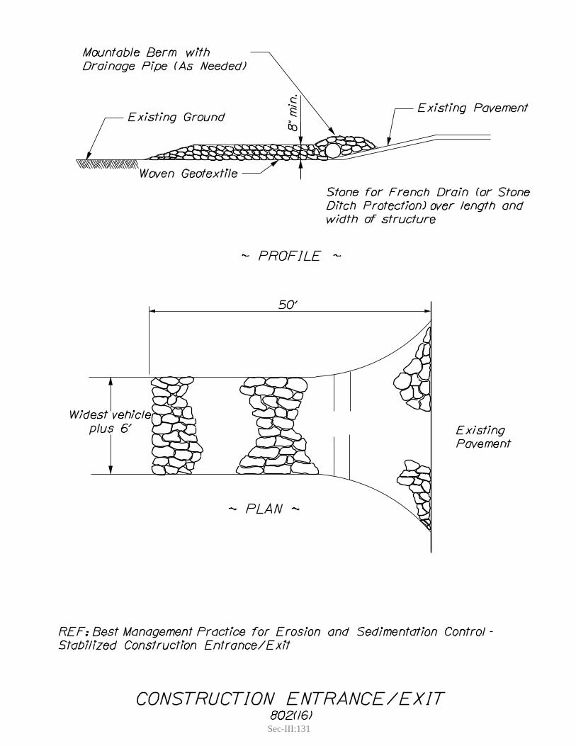
Sec-III:131

Sec-III:133
4. WINTER STABILIZATION
Definition and PurposeThis BMP includes practices which will provide for stabilization of soils during winter conditions, frozen ground, and spring thaws.
Appropriate Applications
Any area of exposed soil that does not have adequate cover to prevent erosion through the winter fas determined by the Resident and/or the SWQU staff. It does not include gravel road base or gravel shoulders. fIt does include areas that were seeded and mulched before November 1st but do not have 90% fcover as specified in Standard Specification 618 – Seeding.
Limitations
Subject to weather conditions. Successful implementation of erosion control measures cannot fbe guaranteed when applied over frozen or snow covered ground. Permanent stabilization of disturbed soils prior to November 1st is always preferred.Germination rates for areas seeded after October 15 will be lower than otherwise expected. fReseeding in spring is likely.Cellulose fiber mulch is not acceptable for winter stabilization. f
Standards and SpecificationsTemporary winter stabilization must be used between November 1 and April 1 or outside of that ftime period if the ground is frozen or snow covered. Temporary winter stabilization involves, at a minimum, covering all disturbed soils and seeded ground that is not “Acceptable Work” with an approved method. If temporary winter stabilization practices are used, spring procedures for permanent stabilization shall also be described in the SEWPCP. Use of these methods for over-winter temporary erosion control will be incidental to the contract and be paid for as part of Pay Item 656.75Mulch (either hay or straw or erosion control mix), stone, or erosion control blanket shall not be fapplied on top of snow. The snow shall first be removed down to 1 inch or less in depth.Groundwater seeps and/or surface runoff shall be anticipated and given consideration when fwinter stabilization involves backslopes. The water shall be either diverted into a temporary pipe or carried in a riprap downspout to a stabilized channel. Sheet and rill winter erosion control methods f
Double application of y hay or straw mulch at 150 lbs/1000 sf ( 3 tons/acre) properly anchored; see Hay and Straw Mulch - SR-EC. Erosion control mix applied to a thickness of 4 inches; see y Erosion Control Mix - SR-EC. In the spring, the contractor shall either remove the erosion control mix and apply permanent seed and mulch in accordance with Standard Specification 618 - Seeding, or seed over the erosion control mix with seed mix method 3 or a specialty mix provided by the MaineDOT Landscape Unit.
Sec-III:134
Concentrated flow winter erosion control methods: fPermanent stabilization BMPs of stone or y erosion control blanket (SR-EC). No other measures required.
Winter sedimentation control measures - no additional measures required but existing BMPs fshall be in place and clean of accumulated sediment as of November 1st.
Application Procedures
Consult appropriate BMP section for each type described above. f
Maintenance and Inspections
Inspections shall be made after each rainfall, and/or thaw event during the winter. Eroding areas fshall be repaired immediately and additional BMPs installed as necessary to prevent future erosion. Sediment shall be removed from behind sediment barriers when half full (snow shall be removed as necessary to check sediment levels).
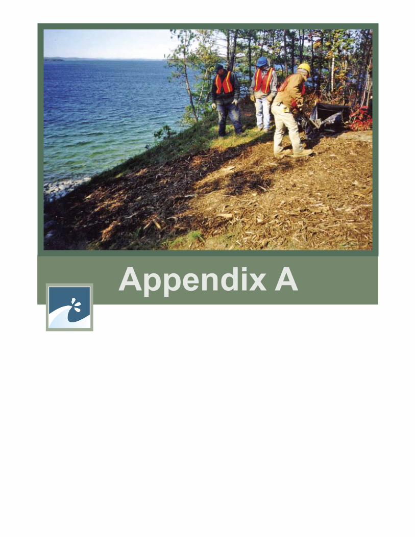
Appendix A


App-A:1
SOIL & WATER CONSERVATION DISTRICTSAndroscoggin Valley Soil & Water Conservation District254 Goddard RoadPO BOX 1938Lewiston, ME 04241Telephone: (207)753-9400Fax: (207)783-4104E-mail: [email protected] Web Site: www.androscogginswcd.net
Central Aroostook Soil & Water Conservation District735 Main Street, Suite #3Presque Isle, ME 04769Telephone: (207)764-4153Fax: (207)768-3407E-mail: [email protected] Site: www.caswcd.org
Cumberland County Soil & Water Conservation District35 Main StreetWindham, ME 04062Tel: (207) 892-4700Fax: (207) 892-4773E-mail: [email protected] Site: www.cumberlandswcd.org
Franklin County Soil & Water Conservation District107 Park StreetFarmington, ME 04938Telephone: (207)778-4279Fax: (207)778-5785E-mail: [email protected]
Hancock County Soil & Water Conservation District190 Bangor RoadEllsworth, ME 04605Telephone: (207)664-7496Fax: (207)667-3585E-mail: [email protected] Site: www.ellsworthme.org/soilandwater
Kennebec County Soil & Water Conservation District21 Enterprise Drive, Suite #1Augusta, ME 04330Telephone: (207)622-7847Fax: (207)626-8196E-mail: [email protected] Site: www.kcswcd.org

App-A:2
Knox-Lincoln Soil & Water Conservation District191 Camden RoadWarren, ME 04864Telephone: (207)273-2005Fax: (207)273-2228E-mail: [email protected] Site: www.knox-lincoln.org
Oxford County Soil & Water Conservation District1570 Main Street, Suite 10Oxford, ME 04270Telephone: (207)743-5789Fax: (207)743-6256E-mail: [email protected]
Penobscot County Soil & Water Conservation District1423 Broadway, Suite 2Bangor, ME 04401Telephone: (207)990-3676Fax: (207)942-1782E-mail: [email protected] Site: www.penobscotswcd.org
Piscataquis County Soil & Water Conservation District42 Pine Crest DriveDover-Foxcroft, ME 04426Telephone: (207)564-2321Fax: (207)564-2570E-mail: [email protected] Site: www.piscataquisswcd.org
St. John Valley Soil & Water Conservation District139 Market Street, Suite 106Fort Kent, ME 04743Telephone: (207)834-3311Fax: (207)834-6435E-mail: [email protected] Site: www.sjv.me.nacdnet.org
Somerset County Soil & Water Conservation District12 High StreetSkowhegan, ME 04967Telephone: (207)474-8324Fax: (207)474-0638E-mail: [email protected] Site: www.somersetswcd.org

App-A:3
Southern Aroostook Soil & Water Conservation District304 North StreetHoulton, ME 04730Telephone: (207)532-2087Fax: (207)532-4379E-mail: [email protected] Site: www.saswcd.org
Waldo County Soil & Water Conservation District266 Waterville RoadBelfast, ME 04915Telephone: (207)338-1964Fax: (207)338-4972E-mail: [email protected]
Washington County Soil & Water Conservation District51 Court StreetPO BOX 121Machias, ME 04654Telephone: (207)255-4659Fax: (207)255-6817E-mail: [email protected] Site: www.downeastsoilwater.org
York County Soil & Water Conservation District21 Braden StreetSpringvale, ME 04083Telephone: (207)324-0888Fax: (207)324-4462E-mail: [email protected] Site: www.yorkswcd.org

Appendix B


App-B:1
App-B:2
App-B:3
App-B:4
App-B:5
App-B:6
Appendix C

App-C:1
SeCTion 656 - TemPoRARy Soil eRoSion AND WATER POLLUTION CONTROL 656.1 Responsibility of the Contractor-Prepare and Follow Plan. The Contractor shall provide continuous and effective temporary soil erosion and water pollution control for the Project that is appropriate to the construction means, methods and sequencing allowed by the Contract and selected by the Contractor. To do so, the Contractor shall prepare and submit a Soil Erosion and Water Pollution Control Plan (SEWPCP) and properly implement its approved SEWPCP. The Contractor shall have its SEWPCP approved, perform a preconstruction field review, and install and certify initial controls before commencing any Work, which could disturb soils or impact water quality.
If the Contractor properly implements its approved SEWPCP, then (1) any Work required in excess of that required by the SEWPCP will be Extra Work, (2) any Delay resulting from any such excess Work will be analyzed in accordance with Section 109.5 - Adjustments for Delay, and (3) the Contractor will not be responsible for damages relating to insufficient soil erosion and water pollution control including the cost of all environmental enforcement actions, penalties, or monetary settlements assessed by any environmental regulatory entity, and all costs incurred by or through the Department.
If the Contractor fails to prepare, submit, or seek approval of a SEWPCP or fails to properly implement its approved SEWPCP, then (1) the Department may suspend all Work, (2) the Department may withhold all Progress Payments or any portion thereof until the Contractor remedies all deficiencies; (3) the Department may remedy deficiencies with Departmental or contracted forces and deduct the cost thereof from payments otherwise due the Contractor; (4) any delay resulting from such failure or non-compliance will be a Non-excusable Delay; and (5) the Contractor will be responsible for all damages arising from or related to such failure or non-compliance including the cost of all environmental enforcement actions, penalties, or monetary settlements assessed by any environmental regulatory entity and all costs incurred by or through the Department including legal and consulting fees.
656.2 Submittal and Approval of the SEWPCP. Within 21 calendar days of Contract Execution, the Contractor must submit two copies of its SEWPCP to the Resident.
Within 14 days of receipt, the Department will determine if the SEWPCP is in accordance with the Contract requirements and (1) notify the Contractor that its SEWPCP is approved or (2) return it for any needed revisions. If returned for revision, the Contractor must resubmit two copies of its revised SEWPCP as provided above within 7 days and the Department will have 7 days from receipt of the revised plan to notify the Contractor whether its SEWPCP is approved or again requires revision. Additional iterations will occur in a like manner until the Department approves the Contractor’s SEWPCP. The Contractor must have its SEWPCP approved and implemented before commencing any Work, which could disturb soils or impact water quality.
SEWPCP REQUIREMENTS656.3.1 Qualifications of Preparer. The preparer of the SEWPCP must be knowledgeable and experienced in erosion and pollution control and must (1) be a “DEP Certified Contractor” as designated by the Maine Department of Environmental Protection (MDEP), or (2) be licensed in Maine as a Professional Engineer, Landscape Architect, or Soil Scientist.
App-C:2
656.3.2 Standards. The SEWPCP must be in accordance with all applicable laws, rules, regulations, permit requirements and conditions, this specification, all other contractual provisions, and the latest version of Department’s “Best Management Practices for Erosion & Sedimentation Control” (the “BMP Manual”). In the event of conflicting provisions, the SEWPCP must utilize the more restrictive requirements. If the Work could disturb soils in the watersheds of any sensitive waterbodies identified in the Contract documents, then the SEWPCP must be in accordance with the higher standards for soil erosion and water pollution contained in Section II (D) - “Guidance for Sensitive Waterbodies” of the BMP Manual.
656.3.3 General SEWPCP Elements. In addition to other requirements provided for or referenced in this specification, the SEWPCP must include the following elements.
a. The name and qualifications of the person preparing the SEWPCP.
b. The name of the on-site person, the “Environmental Coordinator” responsible for implementation of the SEWPCP, who must be the Prime Contractor’s Superintendent or other supervisory employee with the authority to immediately remedy any deficient controls, with their phone number and emergency number (personal cellular phone or pager).
c. The schedule and sequence of all activities that involve soil disturbance including work on sites outside the right-of-way such as borrow pit operations, haul roads, staging areas, equipment storage sites, mixing plants, and waste disposal sites including expansion of existing sites.
d. Incorporation of permanent erosion control features into the project at the earliest practicable time.
e. Identification of steep slopes and highly erodible soils, with the method and frequency of soil stabilization.
f. Emergency procedures for storms, including availability of Materials and procedures and time frames for corrective action if controls fail.
g. A discussion of how the SEWPCP meets or exceeds the Standards and Commitments contained in Section II of the BMP Manual.
h. Type and location of all temporary erosion and sedimentation control measures. Temporary winter stabilization must be used between November 1 and April 1, or outside of said time period if the ground is frozen or snow covered. Temporary winter stabilization involves, at a minimum, covering all disturbed soils with some method other than using unanchored hay or straw mulch. Such other methods may include the use of Erosion Control Mix or other covers that are not susceptible to erosion or wind movement. If temporary winter stabilization practices are used, spring procedures for permanent stabilization shall also be described in the SEWPCP.
i. Mulching type and frequency of application for disturbed soil areas.
j. Location and frequency of application of temporary seeding.
k. Description of all dust control procedures for roadways, haul roads, work areas, and all other contractor activities.
l. Location and method of temporary sediment control for existing and proposed catch basins and all other drainage inlet and outlet areas.
m. Describe all in-water work, with timing and plans for temporary stream diversions and cofferdams.
App-C:3
n. Describe the design, location, and plans for sedimentation basins used for dewatering cofferdams.
o. Inspection and maintenance schedules for all erosion and water pollution control measures - temporary and permanent - including the method, frequency and disposal location for sediment removal.
p. Temporary erosion control features for any designated mitigation site that is specified in the Contract.
q. Procedures for removal of temporary erosion and pollution controls.
656.3.4 Water Pollution Control Requirements. In addition to other requirements provided for or referenced in this specification, the SEWPCP must include all of the following requirements applicable to water pollution control.
a. The Contractor must comply with the applicable Federal, state, and Local laws, and regulations relating to prevention and abatement of water pollution.
b. Except as allowed by an approved permit or otherwise authorized by the Department in writing, pollutants and construction debris including excavated material, aggregate, residue from cleaning, sandblasting, or painting, cement mixtures, chemicals, fuels, lubricants, bitumens, raw sewage, wood chips, and other debris shall not be discharged into waterbodies, wetlands, or natural or man-made channels leading thereto and such materials shall not be located alongside waterbodies, wetlands, or such channels such that it will be washed away by high water or runoff.
c. Construction operations in waterbodies or wetlands shall be restricted to the construction limits shown on the plans and to those areas that must be entered for the construction of temporary or permanent structures, except as allowed by approved permit or otherwise authorized by the Department in writing.
d. Mechanized equipment shall not be operated in waterbodies or wetlands, except as allowed by approved permit or otherwise authorized by the Department in writing.
e. Upon completion of the work, waterbodies or wetlands shall be promptly cleared of all falsework, piling, debris or other obstructions caused by the construction operations, except as otherwise authorized by the Department in writing.
f. Spill Prevention. If the Work includes the handling, use, or storage of petroleum products or hazardous Matter/Substances including the on site fueling of Equipment, the SEWPCP must include a Spill Prevention Control and Countermeasure Plan (SPCCP). At a minimum, the SPCCP must include:
1. The name and emergency response numbers (telephone number, cellular phone and pager numbers, if applicable) of the Contractor’s representative responsible for spill prevention and response;
2. General description and location of (1) handling, transfer, storage, and containment facilities of such products or hazardous Matter/Substances (“activities and facilities”) and (2) potential receptors of such products or hazardous Matter/Substances including oceans, lakes, ponds, rivers, streams, wetlands, and sand and gravel aquifers (“sensitive resources”) including the distances between said activities and facilities and said sensitive resources;
3. Description of preventative measures to be used to minimize the possibility of a spill

App-C:4
including Equipment and/or Materials to be used to prevent discharges including containment and diversionary structures, inspections and personnel training;
4. A contingency response plan to be implemented if spill should occur including a list of emergency phone/pager numbers including the Contractor’s representative, MDEP Spill Response, the Resident, and local police and fire authorities, a list of emergency response equipment and locations and a description of the capabilities of the equipment, a description of the general response and clean up protocols by product or Matter/Substances and an overview of the verbal and written notification procedures for Federal, state and Local officials. For a related provision, see 105.2.2 - “Project Specific Emergency Planning”.
For a related provision, see Section 105.8.3 - “Wetland and Waterbody Impacts”.
656.3.5 Material Requirements. Unless otherwise approved by the Department, the Contractor must use temporary erosion control Materials contained on the Department’s Preapproved List of Erosion Control Materials if such a list is established, the Department’s latest BMP Manual, or Section 717 - Roadside Improvement Materials.
656.3.6 Construction Requirements. In addition to other requirements provided for or referenced in this specification, the SEWPCP must include all of the following requirements applicable during construction.
a. The Contractor shall install and maintain all temporary erosion control Materials in accordance with the Manufacturer’s Guidelines and Specifications, or the Department’s latest BMPs or Standard Specification where applicable.
b. The Contractor shall perform in-water work during low flow conditions, except as allowed by a specific Permit requirement. During in-water work, the Contractor shall maintain water flow at all times except in ponded water or where specifically authorized. The Contractor, to the maximum extent practicable, shall place pipes in dry conditions.
c. The Contractor, to the maximum extent practicable, shall install temporary and permanent erosion control measures prior to conducting clearing and grubbing operations. The Contractor shall not conduct clearing operations within any protected vegetative buffer area indicated in the plans, notes, or special provisions. The Contractor shall limit excavation, borrow and embankment operations commensurate with its capability and progress in keeping the finish grading, mulching, seeding, and other such temporary and permanent erosion control measures current in accordance with its schedule. Should seasonal limitations make such coordination impractical, temporary erosion control measures shall be provided immediately.
d. The Contractor shall not work in a wetland, except as allowed by a specific permit provision. All equipment which must work in a wetland shall travel and work on platforms or mats that protect vegetation which the Department has designated to remain. The Contractor shall not store or stockpile materials in a wetland. The Contractor shall contain and immediately remove from the wetland or waterbody any debris generated by the Work
e. The Contractor shall not place uncured concrete directly into a waterbody. The Contractor shall not wash tools, forms, or other items in or adjacent to a waterbody or wetland.
f. The Contractor shall contain all demolition debris (including debris from wearing surface removal, saw cut slurry, dust, etc.) and shall not allow it to discharge to any resource. All demolition debris shall be disposed of in accordance with Section 202.03 - Removing Existing Superstructure, Structural Concrete, Railings, Curbs, Sidewalks and Bridges. The Contractor shall dispose of
App-C:5
debris in accordance with the Maine Solid Waste Law, Title 38 M.R.S.A., Section 1301 et. seq. Containment and disposal of demolition debris shall be addressed in the Contractor’s SEWPCP.
g. The Contractor shall air dry all treated lumber for at least 21 days before use. All treated timber surfaces shall be exposed during air-drying.
h. The Contractor shall place all permanent seeding in accordance with Section 618 - Seeding unless the Contract states otherwise. The Contractor shall state what additional measures they will employ for soil stabilization between November 1st and April 1st.
i. The Contractor shall not remove rocks from below the normal high water line of any wetland, great pond, river, stream, or brook, except to the extent necessary for completion of the Work and as allowed by environmental permits. The Contractor shall not work below the high water line of a great pond, river, stream, or brook during periods of elevated water, except as necessary to protect work in progress or for emergency flood control and as allowed by environmental permits.
j. During periods of approved suspension, the Contractor shall inspect and maintain temporary and permanent erosion controls in accordance with its approved SEWPCP.
k. All sites of disturbed soil outside the right-of-way such as haul roads, staging areas, Equipment storage sites, mixing plants, and waste disposal sites including expansion of existing sites shall be graded smooth, loamed, seeded, and mulched upon completion of the work. For a related provision, see Section 105.8.6 - Pit Requirements.
IMPLEMENTATION OF SEWPCP656.4.1 Preconstruction Field Review. Before commencing any Work, that could disturb soils or impact water quality, the preparer of the SEWPCP and the Environmental Coordinator must field review the project. The Contractor shall provide the Department at least three days prior notice of this review.
656.4.2 Preconstruction Installation of Controls/Certification. Before commencing any Work, which could disturb soils or impact water quality, initial soil erosion and water pollution controls must be installed in compliance with the Contractor’s SEWPCP and the Environmental Coordinator must so certify to the Department in writing.
656.4.3 Follow Plan Until Acceptance of the Work, the Contractor must continuously provide soil erosion and water pollution controls in compliance with its approved SEWPCP as amended, if necessary, and in compliance with Section 656.4.5 - Additional Measures/Amendment of SEWPCP.
656.4.4 Inspection and Record Keeping. The Environmental Coordinator must inspect and monitor all controls for the duration of the project and keep a written log. This log must include daily on-site precipitation and air temperature, as well as the performance, failure, and any corrective action for all controls in place. The log must be updated at least weekly and after all significant storm runoff and flood events. The Environmental Coordinator must make this log available to the Department upon request. The Contractor will retain the log for three years after the completion of the project.
656.4.5 Additional Measures/Amendment of SEWPCP If there exists observable evidence of erosion or sedimentation despite the installation of all controls in compliance with the Contractor’s approved SEWPCP, then the Contractor must undertake such additional measures as are necessary to stop such erosion and prevent further erosion or sedimentation. Observable evidence of erosion or sedimentation includes visible sheet, rill, or gully erosion, discoloration of water by suspended particles, areas of sediment accumulation,
App-C:6
slumping of banks, deposition of soil, and visible dust. Such additional measures must be undertaken within 24 hours and completed within 48 hours from the time such evidence is observed, unless otherwise authorized by the Department. Within 7 days of that time, the Contractor must submit an amendment to its SEWPCP setting forth the apparent cause of the erosion or sedimentation and the additional measures undertaken and that will continue to be undertaken. If the Contractor complies with the requirements of this Section, all additional measures and the amendment of the SEWPCP will be Extra Work and any Delay resulting from the additional measures will be analyzed in accordance with Section 109.5 - Adjustments for Delay.
656.4.6 Duration of Contractor’s Responsibility. The Contractor shall provide temporary soil erosion and water pollution controls in compliance with its SEWPCP and maintain all permanent control features until Acceptance of the Work. Once final surface treatments are established, the Contractor is responsible for removal of all temporary sedimentation control practices such as silt fence. Notwithstanding the preceding sentence, all work needed to remedy damage to properly installed and maintained permanent control features caused by a weather-related Uncontrollable Event shall be Extra Work.
PAYMENT656.5.1 If Pay Item 656.75 Provided. If the Schedule of Items contains Pay Item 656.75 for Temporary Soil Erosion and Water Pollution Control, payment will be made on a Lump Sum basis, payment of which will constitute full and complete compensation for all labor, equipment, materials, inspection, professional services, and incidentals necessary to prepare, submit, obtain approval of, and properly implement the Contractor’s SEWPCP. The Lump Sum will be payable in installments as follows: 10% of the Lump Sum once the final SEWPCP is approved and the initial soil erosion and water pollution controls are in place and certified by the Contractor, with the 90% balance to be paid as the Work progresses at a rate proportional to the percentage completion of the Contract.
Failure by the Contractor to comply with its SEWPCP and/or failure to implement additional measures will result in a reduction in payment, computed by reducing the 90% balance (a) by the number of days deficient divided by the number of days from start of work to project completion or (b) $100 for each day deficient, whichever is greater. Payment may be further adjusted as provided in Section 656.1 - Responsibility of the Contractor - Prepare and Follow Plan.
Cofferdams and related temporary soil erosion and water pollution controls are incidental to the Pay Item 656.75, unless a specific pay item for cofferdams is included in the Schedule of Items. If a specific pay item for cofferdams is included, then related temporary soil erosion and water pollution controls, including inspection and maintenance, are incidental to the pay item for cofferdams.
656.5.2 If No Pay Item. If Pay Item 656.75 is not provided in the Schedule of Items, then the cost related thereto shall be Incidental to the Contract.
Payment will be made under:
Pay Item Pay Unit 656.75 Temporary Soil Erosion and Water Pollution Control Lump Sum
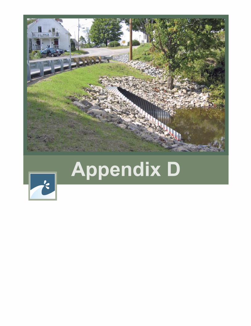
Appendix D

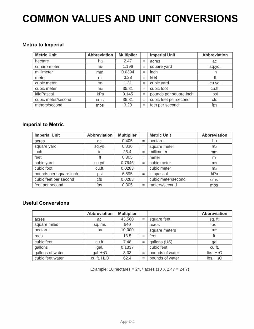
App-D:1
Metric Unit Abbreviation Multiplier Imperial Unit Abbreviation hectare ha 2.47 = acres acsquare meter m2 1.196 = square yard sq.yd. millimeter mm 0.0394 = inch inmeter m 3.28 = feet ftcubic meter m3 1.31 = cubic yard cu.yd. cubic meter m3 35.31 = cubic foot cu.ft. kiloPascal kPa 0.145 = pounds per square inch psicubic meter/second cms 35.31 = cubic feet per second cfsmeters/second 3.28 feet per second fpsmps =
Imperial Unit Abbreviation Multiplier Metric Unit Abbreviation 0.405 hectare haacres ac =
square yard sq.yd. 0.836 m2= square meter inch in 25.4 millimeter= mmfeet ft 0.305 = meter mcubic yard cu.yd. 0.7646 cubic meter m3=cubic foot cu.ft. 0.0283 cubic meter m3=pounds per square inch psi 6.895 kilopascal kPa=cubic feet per second cfs 0.0283 cubic meter/second = cms feet per second fps 0.305 meters/second = mps
Abbreviation Multiplier Abbreviation 43,560 square feet sq. ft. acres ac =
square miles sq. mi. 640 = acres acm2hectare ha 10,000 square meters
rods 16.5 feet ft.=cubic feet cu.ft. 7.48 gallons (US) gal=gallons gal. 0.1337 cubic feet cu.ft. =gallons of water gal.H2O 8.33 pounds of water lbs. H2O=cubic feet water cu.ft. H2O 62.4 pounds of water lbs. H2O=
Example: 10 hectares = 24.7 acres (10 X 2.47 = 24.7)
Metric to Imperial
Imperial to Metric
Useful Conversions
COMMON VALUES AND UNIT CONVERSIONS