main features - roland advanced control and expandability delivers infinite creative possibilities....
TRANSCRIPT
Owner’s Manual
Owner’s Manual (this document)Read this first. It explains the basic things you need to know in order to use the MS-3. For detailed information on how to operate the MS-3, please download and refer to “Parameter Guide” (PDF file).
PDF Manual (download from the Web) 5 Parameter Guide
This explains all of the parameters of the MS-3. It also contains a list of the sounds that are built into the MS-3.The Parameter Guide can also be viewed using the dedicated software.
5 Application GuideThis explains example setups for the MS-3 and how to make settings.
5 MIDI ImplementationThis is detailed information about MIDI messages.
To obtain the PDF manual1. Enter the following URL on your
computer.http://www.boss.info/manuals/
?2. Choose “MS-3” as the product name.
Before using this unit, carefully read “USING THE UNIT SAFELY” and “IMPORTANT NOTES” (the leaflet “USING THE UNIT SAFELY” and the Owner’s Manual (p. 20)). After reading, keep the document(s) where it will be available for immediate reference.
Copyright © 2017 ROLAND CORPORATION
Main featuresPedalboard Integration Evolved
5 Integrated system with versatile built-in effects plus three loops for your favorite pedals.
5 Space-saving design enables you to create a compact pedalboard with sophisticated functionality.
5 Advanced control and expandability delivers infinite creative possibilities.
2
ContentsGetting Ready . . . . . . . . . . . . . . . . . . . . . . . 3
Rear Panel (Connecting Your Equipment) . . . . . . . . 3
Top Panel . . . . . . . . . . . . . . . . . . . . . . . . . . 5
Screen Structure . . . . . . . . . . . . . . . . . . . 6
Operation of the [1]–[3] Knobs . . . . . . . 7
Switching Pages . . . . . . . . . . . . . . . . . . . . 7
Turning On/Off the Power . . . . . . . . . . . 8
Tuning the Guitar (TUNER) . . . . . . . . . . . 8
Playing . . . . . . . . . . . . . . . . . . . . . . . . . . . . . . 9
Patch Structure . . . . . . . . . . . . . . . . . . . . . 9
Switching Between Memory and Manual Modes . . . . . . . . . . . . . . . . . . . . . 9
Switching Banks/Patches . . . . . . . . . . . . 10
About the Play Screen . . . . . . . . . . . . . . . 10
Editing the Settings of a Patch . . . . . . . 11
Basic Operation . . . . . . . . . . . . . . . . . . . . 11
Changing the Effect Connection Order . . . . . . . . . . . . . . . . . . . . . . . . 12
Changing the CTL/ASSIGN/MIDI Settings . . . . . . . . . . . . . . . . . . . . . . 12
Saving a Patch . . . . . . . . . . . . . . . . . . . . . 13
Exchanging Patches . . . . . . . . . . . 14
Initializing a Patch . . . . . . . . . . . . . 14
System Settings (MENU) . . . . . . . . . . . . . 15
Basic Operation . . . . . . . . . . . . . . . . . . . . 15
Adjusting the Display Contrast . . . . . . . 15
Enabling/Disabling the Auto-Off Function . . . . . . . . . . . . . . . . . . . . . . . . . . 16
Restoring the Factory Default Settings (Factory Reset) . . . . . . . . . . . . . . . . . . . . . 16
Using a Computer to Edit/Back up Patches . . . . . . . . . . . . . . . . . . . . . . . . . . . . . . 17
Installing the USB Driver . . . . . . . . . . . . . 17
Installing the Dedicated Software . . . . 17
Appendix . . . . . . . . . . . . . . . . . . . . . . . . . . . . 18
Error Messages . . . . . . . . . . . . . . . . . . . . . 18
Attaching the Rubber Feet . . . . . . . . . . . 18
Block Diagram . . . . . . . . . . . . . . . . . . . . . 18
Main Specifications . . . . . . . . . . . . . . . . . 19
USING THE UNIT SAFELY . . . . . . . . . . . . . 20
IMPORTANT NOTES . . . . . . . . . . . . . . . . . . 20
The power to this unit will be turned off automatically after a predetermined amount of time has passed since it was last used for playing music, or its buttons or controls were operated (Auto Off function).If you do not want the power to be turned off automatically, disengage the Auto Off function (p. 16).
NOTE
5 Any settings that you are in the process of editing will be lost when the power is turned off. If you have any settings that you want to keep, you should save them beforehand.
5 To restore power, turn the power on again (p. 8).
3
Getting ReadyRear Panel (Connecting Your Equipment)
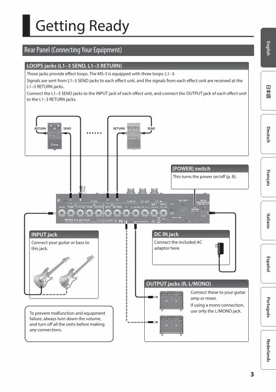
LOOPS jacks (L1–3 SEND, L1–3 RETURN)These jacks provide effect loops. The MS-3 is equipped with three loops: L1–3.Signals are sent from L1–3 SEND jacks to each effect unit, and the signals from each effect unit are received at the L1–3 RETURN jacks.Connect the L1–3 SEND jacks to the INPUT jack of each effect unit, and connect the OUTPUT jack of each effect unit to the L1–3 RETURN jacks.
SENDRETURN SENDRETURN
OUTPUT jacks (R, L/MONO)Connect these to your guitar amp or mixer. If using a mono connection, use only the L/MONO jack.
DC IN jackConnect the included AC adaptor here.
To prevent malfunction and equipment failure, always turn down the volume, and turn off all the units before making any connections.
[POWER] switchThis turns the power on/off (p. 8).
INPUT jackConnect your guitar or bass to this jack.
4
Getting Ready
Rear Panel (Connecting Your Equipment)
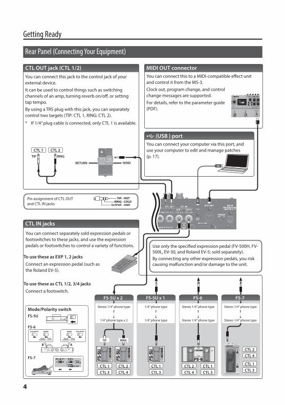
CTL OUT jack (CTL 1/2)You can connect this jack to the control jack of your external device.It can be used to control things such as switching channels of an amp, turning reverb on/off, or setting tap tempo.By using a TRS plug with this jack, you can separately control two targets (TIP: CTL 1, RING: CTL 2).
* If 1/4” plug cable is connected, only CTL 1 is available.
To use these as EXP 1, 2 jacksConnect an expression pedal (such as the Roland EV-5).
To use these as CTL 1/2, 3/4 jacksConnect a footswitch.
FS-5U x 2
RINGTIP
Stereo 1/4” phone type./
1/4” phone type x 2
FS-6 FS-7
CTL 2
FS-5U x 1
FS-5U
FS-6
Mode/Polarity switch
FS-7
1/4” phone type./
1/4” phone type
Stereo 1/4” phone type./
Stereo 1/4” phone type
Stereo 1/4” phone type./
Stereo 1/4” phone type
CTL 1CTL 2 CTL 1CTL 1CTL 1 CTL 2
TIP RING
CTL 1 CTL 2
SENDRETURN
CTL IN jacks
You can connect separately sold expression pedals or footswitches to these jacks, and use the expression pedals or footswitches to control a variety of functions.
CTL 3 CTL 4 CTL 3 CTL 4 CTL 3
CTL 4
CTL 3
Use only the specified expression pedal (FV-500H, FV-500L, EV-30, and Roland EV-5; sold separately). By connecting any other expression pedals, you risk causing malfunction and/or damage to the unit.
MIDI OUT connectorYou can connect this to a MIDI-compatible effect unit and control it from the MS-3.Clock out, program change, and control change messages are supported.For details, refer to the parameter guide (PDF).
O (USB ) portYou can connect your computer via this port, and use your computer to edit and manage patches (p. 17).
Pin assignment of CTL OUT and CTL IN jacks
5
Getting Ready
Top Panel
1
2
3
4
5
6
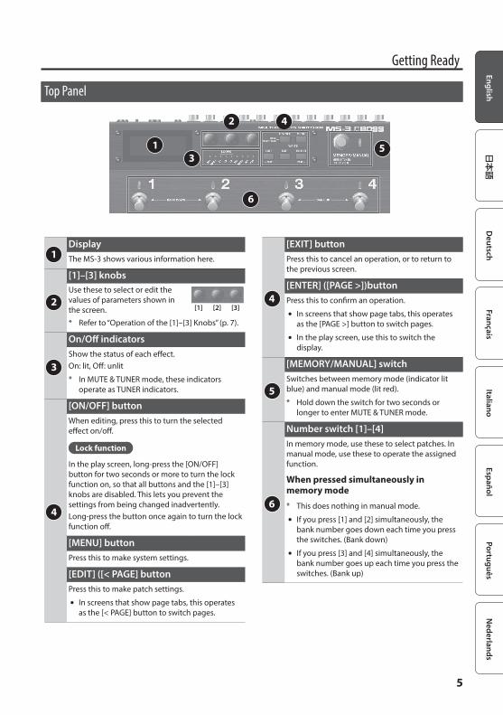
1 DisplayThe MS-3 shows various information here.
2
[1]–[3] knobsUse these to select or edit the values of parameters shown in the screen. [1] [2] [3]
* Refer to “Operation of the [1]–[3] Knobs” (p. 7).
3
On/Off indicatorsShow the status of each effect.On: lit, Off: unlit
* In MUTE & TUNER mode, these indicators operate as TUNER indicators.
4
[ON/OFF] buttonWhen editing, press this to turn the selected effect on/off.
Lock function
In the play screen, long-press the [ON/OFF] button for two seconds or more to turn the lock function on, so that all buttons and the [1]–[3] knobs are disabled. This lets you prevent the settings from being changed inadvertently.Long-press the button once again to turn the lock function off.
[MENU] buttonPress this to make system settings.
[EDIT] ([< PAGE] buttonPress this to make patch settings.
5 In screens that show page tabs, this operates as the [< PAGE] button to switch pages.
4
[EXIT] buttonPress this to cancel an operation, or to return to the previous screen.
[ENTER] ([PAGE >])buttonPress this to confirm an operation.
5 In screens that show page tabs, this operates as the [PAGE >] button to switch pages.
5 In the play screen, use this to switch the display.
5
[MEMORY/MANUAL] switchSwitches between memory mode (indicator lit blue) and manual mode (lit red).
* Hold down the switch for two seconds or longer to enter MUTE & TUNER mode.
6
Number switch [1]–[4]In memory mode, use these to select patches. In manual mode, use these to operate the assigned function.
When pressed simultaneously in memory mode
* This does nothing in manual mode.
5 If you press [1] and [2] simultaneously, the bank number goes down each time you press the switches. (Bank down)
5 If you press [3] and [4] simultaneously, the bank number goes up each time you press the switches. (Bank up)
6
Getting Ready
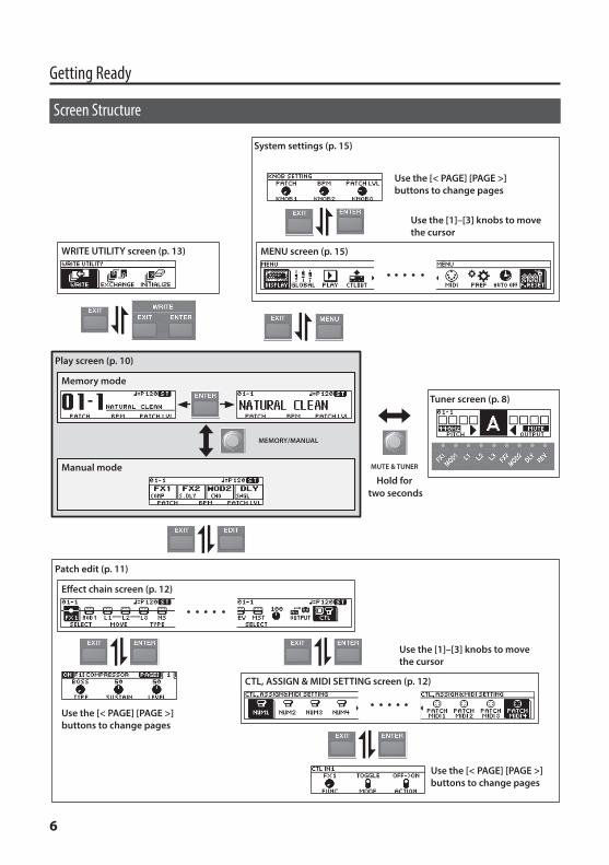
Screen Structure
MUTE & TUNER
Hold for two seconds
Memory mode
Manual mode
Play screen (p. 10)
Tuner screen (p. 8)
Effect chain screen (p. 12)
Patch edit (p. 11)
CTL, ASSIGN & MIDI SETTING screen (p. 12)
WRITE UTILITY screen (p. 13)
System settings (p. 15)
MENU screen (p. 15)
MEMORY/MANUAL
Use the [< PAGE] [PAGE >] buttons to change pages
Use the [< PAGE] [PAGE >] buttons to change pages
Use the [< PAGE] [PAGE >] buttons to change pages
Use the [1]–[3] knobs to move the cursor
Use the [1]–[3] knobs to move the cursor
7
Getting Ready
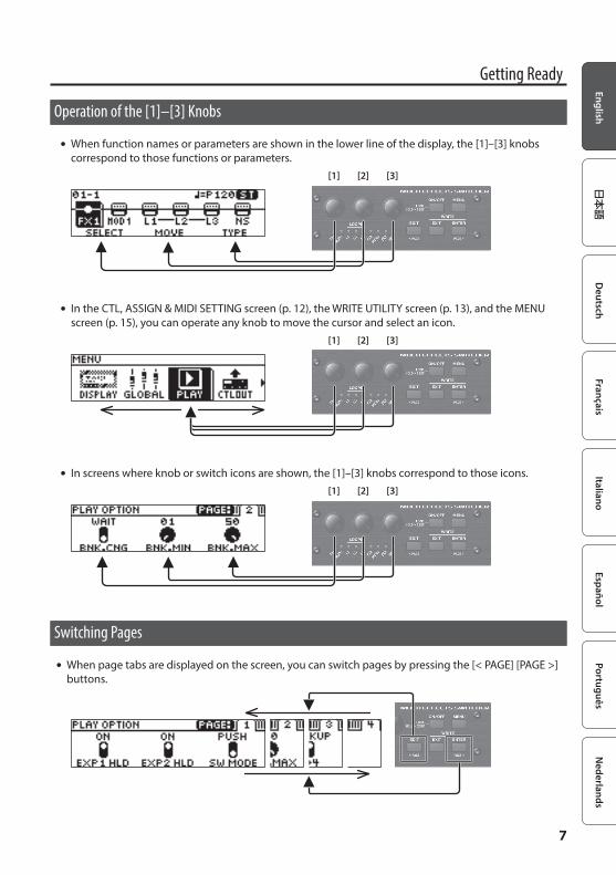
Operation of the [1]–[3] Knobs
5 When function names or parameters are shown in the lower line of the display, the [1]–[3] knobs correspond to those functions or parameters.
[1] [2] [3]
5 In the CTL, ASSIGN & MIDI SETTING screen (p. 12), the WRITE UTILITY screen (p. 13), and the MENU screen (p. 15), you can operate any knob to move the cursor and select an icon.
[1] [2] [3]
5 In screens where knob or switch icons are shown, the [1]–[3] knobs correspond to those icons.[1] [2] [3]
Switching Pages
5 When page tabs are displayed on the screen, you can switch pages by pressing the [< PAGE] [PAGE >] buttons.
8
Getting Ready
Turning On/Off the Power
* Before turning the unit on/off, always be sure to turn the volume down. Even with the volume turned down, you might hear some sound when switching the unit on/off. However, this is normal and does not indicate a malfunction.
When powering up
Turn on the power in the following order: this unit ([POWER] switch: ON) 0 connected equipment 0 guitar amp.
When powering down
Turn off the power in the following order: guitar amp 0 connected equipment 0 this unit ([POWER] switch: OFF).
Tuning the Guitar (TUNER)
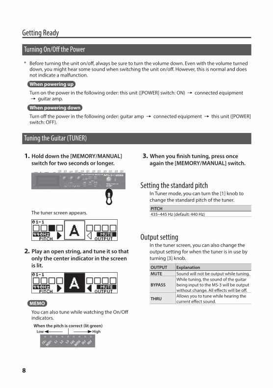
1. Hold down the [MEMORY/MANUAL] switch for two seconds or longer.
The tuner screen appears.
2. Play an open string, and tune it so that only the center indicator in the screen is lit.
MEMO
You can also tune while watching the On/Off indicators.
When the pitch is correct (lit green)HighLow
3. When you finish tuning, press once again the [MEMORY/MANUAL] switch.
Setting the standard pitchIn Tuner mode, you can turn the [1] knob to change the standard pitch of the tuner.
PITCH435–445 Hz (default: 440 Hz)
Output settingIn the tuner screen, you can also change the output setting for when the tuner is in use by turning [3] knob.
OUTPUT ExplanationMUTE Sound will not be output while tuning.
BYPASSWhile tuning, the sound of the guitar being input to the MS-3 will be output without change. All effects will be off.
THRU Allows you to tune while hearing the current effect sound.
9
PlayingPatch Structure
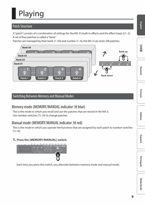
A “patch” consists of a combination of settings for the MS-3’s built-in effects and the effect loops (L1–3).A set of four patches is called a “bank.”Patches are managed by their bank (1–50) and number (1–4); the MS-3 can store 200 patches.
Bank 50
Bank 03
Bank 02
Bank down
Bank 01
Patch 1 Patch 2 Patch 3 Patch 4
Bank up
Switching Between Memory and Manual Modes
Memory mode (MEMORY/MANUAL indicator: lit blue)This is the mode in which you recall and use the patches that are stored in the MS-3.Use number switches [1]–[4] to change patches.
Manual mode (MEMORY/MANUAL indicator: lit red)This is the mode in which you operate the functions that are assigned by each patch to number switches [1]–[4].
1. Press the [MEMORY/MANUAL] switch.
Each time you press this switch, you alternate between memory mode and manual mode.
10
Playing
Switching Banks/Patches
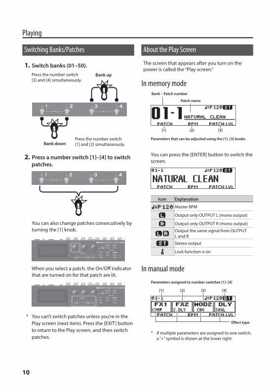
1. Switch banks (01–50).
Bank down
Bank up
Press the number switch [1] and [2] simultaneously.
Press the number switch [3] and [4] simultaneously.
2. Press a number switch [1]–[4] to switch patches.
You can also change patches consecutively by turning the [1] knob.
When you select a patch, the On/Off indicator that are turned on for that patch are lit.
* You can’t switch patches unless you’re in the Play screen (next item). Press the [EXIT] button to return to the Play screen, and then switch patches.
About the Play Screen
The screen that appears after you turn on the power is called the “Play screen.”
In memory modeBank – Patch number
[1] [2] [3]
Parameters that can be adjusted using the [1]–[3] knobs
Patch name
You can press the [ENTER] button to switch the screen.
Icon Explanation
Master BPM
Output only OUTPUT L (mono output)
Output only OUTPUT R (mono output)
Output the same signal from OUTPUT L and R
Stereo output
Lock function is on
In manual modeParameters assigned to number switches [1]–[4]
* If multiple parameters are assigned to one switch, a “+” symbol is shown at the lower right.
[3] [4][1] [2]
Effect type
11
Editing the Settings of a PatchBasic Operation
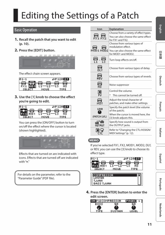
1. Recall the patch that you want to edit (p. 10).
2. Press the [EDIT] button.
The effect chain screen appears.
3. Use the [1] knob to choose the effect you’re going to edit.
You can press the [ON/OFF] button to turn on/off the effect where the cursor is located (shown highlighted).
Effects that are turned on are indicated with icons. Effects that are turned off are indicated with “5.”
For details on the parameter, refer to the “Parameter Guide” (PDF file).
Icon ExplanationChoose from a variety of effect types.You can also choose the same effect for FX1 and FX2.Choose from various types of modulation effect.You can also choose the same effect for MOD1 and MOD2.
– Turn loop effects on/off.
Choose from various types of delay.
Choose from various types of reverb.
Noise suppressor
Control the volume.
* This cannot be turned off.
Adjust the tonal character of patches, and make other settings.
(PATCH LVL)
Specify the patch level (the volume of the patch).When the cursor is moved here, the [3] knob adjusts this.Specify how sound is output from the OUTPUT jacks.
Refer to “Changing the CTL/ASSIGN/MIDI Settings” (p. 12).
MEMOIf you’ve selected FX1, FX2, MOD1, MOD2, DLY, or REV, you can use the [3] knob to choose its effect type.
4. Press the [ENTER] button to enter the edit screen.
12
Editing the Settings of a Patch
MEMO
Pressing the [ON/OFF] button in the edit screen switches the effect’s on/off status. This lets you hear what the effect is doing.
When tabs are displayed on the screen, you can switch pages by pressing the [< PAGE] [PAGE >] buttons.
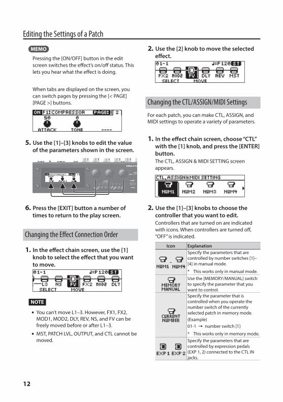
5. Use the [1]–[3] knobs to edit the value of the parameters shown in the screen.
6. Press the [EXIT] button a number of times to return to the play screen.
Changing the Effect Connection Order
1. In the effect chain screen, use the [1] knob to select the effect that you want to move.
NOTE
5 You can’t move L1–3. However, FX1, FX2, MOD1, MOD2, DLY, REV, NS, and FV can be freely moved before or after L1–3.
5 MST, PATCH LVL, OUTPUT, and CTL cannot be moved.
2. Use the [2] knob to move the selected effect.
Changing the CTL/ASSIGN/MIDI Settings
For each patch, you can make CTL, ASSIGN, and MIDI settings to operate a variety of parameters.
1. In the effect chain screen, choose “CTL” with the [1] knob, and press the [ENTER] button.The CTL, ASSIGN & MIDI SETTING screen appears.
2. Use the [1]–[3] knobs to choose the controller that you want to edit.Controllers that are turned on are indicated with icons. When controllers are turned off, “OFF” is indicated.
Icon Explanation
–
Specify the parameters that are controlled by number switches [1]–[4] in manual mode.
* This works only in manual mode.Use the [MEMORY/MANUAL] switch to specify the parameter that you want to control.Specify the parameter that is controlled when you operate the number switch of the currently selected patch in memory mode.(Example)01-1 0 number switch [1]
* This works only in memory mode.Specify the parameters that are controlled by expression pedals (EXP 1, 2) connected to the CTL IN jacks.
13
Editing the Settings of a Patch
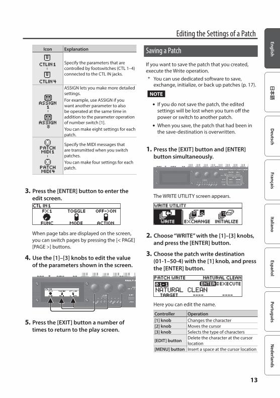
Icon Explanation
–
Specify the parameters that are controlled by footswitches (CTL 1–4) connected to the CTL IN jacks.
–
ASSIGN lets you make more detailed settings.For example, use ASSIGN if you want another parameter to also be operated at the same time in addition to the parameter operation of number switch [1].You can make eight settings for each patch.
–
Specify the MIDI messages that are transmitted when you switch patches.You can make four settings for each patch.
3. Press the [ENTER] button to enter the edit screen.
When page tabs are displayed on the screen, you can switch pages by pressing the [< PAGE] [PAGE >] buttons.
4. Use the [1]–[3] knobs to edit the value of the parameters shown in the screen.
5. Press the [EXIT] button a number of times to return to the play screen.
Saving a Patch
If you want to save the patch that you created, execute the Write operation.* You can use dedicated software to save,
exchange, initialize, or back up patches (p. 17).
NOTE
5 If you do not save the patch, the edited settings will be lost when you turn off the power or switch to another patch.
5 When you save, the patch that had been in the save-destination is overwritten.
1. Press the [EXIT] button and [ENTER] button simultaneously.
The WRITE UTILITY screen appears.
2. Choose “WRITE” with the [1]–[3] knobs, and press the [ENTER] button.
3. Choose the patch write destination (01-1–50-4) with the [1] knob, and press the [ENTER] button.
Here you can edit the name.
Controller Operation[1] knob Changes the character[2] knob Moves the cursor[3] knob Selects the type of characters
[EDIT] button Delete the character at the cursor location
[MENU] button Insert a space at the cursor location
14
Editing the Settings of a Patch
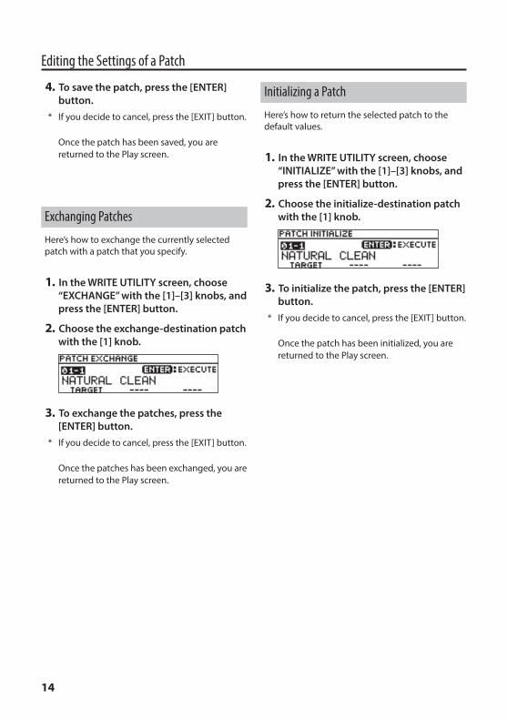
4. To save the patch, press the [ENTER] button.
* If you decide to cancel, press the [EXIT] button.
Once the patch has been saved, you are returned to the Play screen.
Exchanging Patches
Here’s how to exchange the currently selected patch with a patch that you specify.
1. In the WRITE UTILITY screen, choose “EXCHANGE” with the [1]–[3] knobs, and press the [ENTER] button.
2. Choose the exchange-destination patch with the [1] knob.
3. To exchange the patches, press the [ENTER] button.
* If you decide to cancel, press the [EXIT] button.
Once the patches has been exchanged, you are returned to the Play screen.
Initializing a Patch
Here’s how to return the selected patch to the default values.
1. In the WRITE UTILITY screen, choose “INITIALIZE” with the [1]–[3] knobs, and press the [ENTER] button.
2. Choose the initialize-destination patch with the [1] knob.
3. To initialize the patch, press the [ENTER] button.
* If you decide to cancel, press the [EXIT] button.
Once the patch has been initialized, you are returned to the Play screen.
15
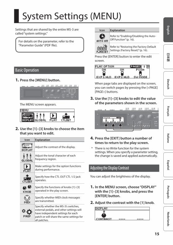
System Settings (MENU)Settings that are shared by the entire MS-3 are called “system settings.”
For details on the parameter, refer to the “Parameter Guide” (PDF file).
Basic Operation
1. Press the [MENU] button.
The MENU screen appears.
2. Use the [1]–[3] knobs to choose the item that you want to edit.
Icon Explanation
Adjust the contrast of the display.
Adjust the tonal character of each frequency region.
Make settings for the option functions during performance.
Specify how the CTL OUT CTL 1/2 jack operates.
Specify the functions of knobs [1]–[3] operated in the play screen.
Specify whether MIDI clock messages are transmitted.
Specify whether the MS-3’s switches, external pedals, and other settings will have independent settings for each patch or will share the same settings for all patches.
Icon Explanation
Refer to “Enabling/Disabling the Auto-Off Function” (p. 16).
Refer to “Restoring the Factory Default Settings (Factory Reset)” (p. 16).
Press the [ENTER] button to enter the edit screen.
When page tabs are displayed on the screen, you can switch pages by pressing the [<PAGE] [PAGE>] buttons.
3. Use the [1]–[3] knobs to edit the value of the parameters shown in the screen.
4. Press the [EXIT] button a number of times to return to the play screen.
* There is no Write function for the system settings. When you specify a parameter setting, the change is saved and applied automatically.
Adjusting the Display Contrast
You can adjust the brightness of the display.
1. In the MENU screen, choose “DISPLAY” with the [1]–[3] knobs, and press the [ENTER] button.
2. Adjust the contrast with the [1] knob.
16
System Settings (MENU)
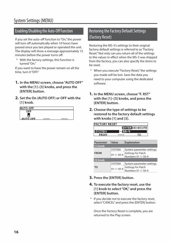
Enabling/Disabling the Auto-Off Function
If you set the auto-off function to “On,” the power will turn off automatically when 10 hours have passed since you last played or operated the unit. The display will show a message approximately 15 minutes before the power turns off.* With the factory settings, this function is
turned “On.”If you want to have the power remain on all the time, turn it “OFF.”
1. In the MENU screen, choose “AUTO OFF” with the [1]–[3] knobs, and press the [ENTER] button.
2. Set the On (AUTO OFF) or OFF with the [1] knob.
Restoring the Factory Default Settings (Factory Reset)
Restoring the MS-3’s settings to their original factory default settings is referred to as “Factory Reset.” Not only can you return all of the settings to the values in effect when the MS-3 was shipped from the factory, you can also specify the items to be reset.
* When you execute “Factory Reset,” the settings you made will be lost. Save the data you need to your computer using the dedicated software.
1. In the MENU screen, choose “F. RST” with the [1]–[3] knobs, and press the [ENTER] button.
2. Choose the type of settings to be restored to the factory default settings with knobs [1] and [3].
Parameter Value Explanation[1] knob
FROMSYSTEM System parameter settings
01-1–50-4 Settings for Patch Numbers 01-1–50-4
[3] knob
TOSYSTEM System parameter settings
01-1–50-4 Settings for Patch Numbers 01-1–50-4
3. Press the [ENTER] button.
4. To execute the factory reset, use the [1] knob to select “OK,” and press the [ENTER] button.
* If you decide not to execute the factory reset, select “CANCEL” and press the [ENTER] button.
Once the Factory Reset is complete, you are returned to the Play screen.
17
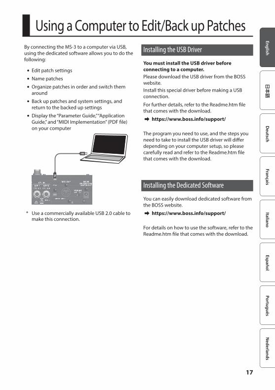
Using a Computer to Edit/Back up PatchesBy connecting the MS-3 to a computer via USB, using the dedicated software allows you to do the following:
5 Edit patch settings
5 Name patches
5 Organize patches in order and switch them around
5 Back up patches and system settings, and return to the backed up settings
5 Display the “Parameter Guide,” “Application Guide,” and “MIDI Implementation” (PDF file) on your computer
* Use a commercially available USB 2.0 cable to make this connection.
Installing the USB Driver
You must install the USB driver before connecting to a computer.Please download the USB driver from the BOSS website.Install this special driver before making a USB connection.
For further details, refer to the Readme.htm file that comes with the download.
& https://www.boss.info/support/
The program you need to use, and the steps you need to take to install the USB driver will differ depending on your computer setup, so please carefully read and refer to the Readme.htm file that comes with the download.
Installing the Dedicated Software
You can easily download dedicated software from the BOSS website.
& https://www.boss.info/support/
For details on how to use the software, refer to the Readme.htm file that comes with the download.
18
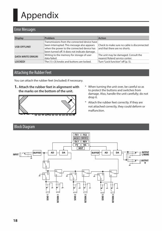
1. Attach the rubber feet in alignment with the marks on the bottom of the unit.
* When turning the unit over, be careful so as to protect the buttons and switches from damage. Also, handle the unit carefully; do not drop it.
* Attach the rubber feet correctly. If they are not attached correctly, they could deform or malfunction.
AppendixError Messages
Display Problem Action
USB OFFLINE!
Transmissions from the connected device have been interrupted. This message also appears when the power to the connected device has been turned off. It does not indicate damage.
Check to make sure no cable is disconnected and that there are no shorts.
DATA WRITE ERROR! Writing to the memory for storage of user data failed.
The unit may be damaged. Consult the nearest Roland service center.
LOCKED! The [1]–[3] knobs and buttons are locked. Turn “Lock function” off (p. 5).
Attaching the Rubber Feet
You can attach the rubber feet (included) if necessary.
Block Diagram
19
Appendix
Main Specifications
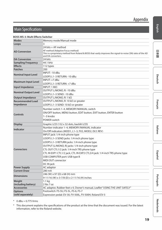
BOSS MS-3: Multi Effects SwitcherModes Memory mode/Manual modeLoops 3
AD Conversion
24 bits + AF methodAF method (Adaptive Focus method) This is a proprietary method from Roland & BOSS that vastly improves the signal-to-noise (SN) ratio of the AD and DA converters.
DA Conversion 24 bitsSampling Frequency 44.1 kHzEffects 112 typesPatches 200
Nominal Input LevelINPUT: -10 dBuLOOPS L1–3 RETURN: -10 dBu
Maximum Input LevelINPUT: +7 dBuLOOPS L1–3 RETURN: +7 dBu
Input Impedance INPUT: 1 MΩ
Nominal Output LevelOUTPUT L/MONO, R: -10 dBuLOOPS L1–3 SEND: -10 dBu
Output Impedance OUTPUT L/MONO, R: 1 kΩRecommended Load Impedance
OUTPUT L/MONO, R: 10 kΩ or greaterLOOPS L1–3 SEND: 10 kΩ or greater
Controls
Number switch 1–4, MEMORY/MANUAL switchON/OFF button, MENU button, EDIT button, EXIT button, ENTER button1–3 knobsPOWER switch
Display Graphic LCD (132 x 32 dots, backlit LCD)
IndicatorNumber indicator 1–4, MEMORY/MANUAL indicatorOn/Off indicators (MOD1, L1–3, FX2, MOD2, DLY, REV)
Connectors
INPUT jack: 1/4-inch phone typeLOOPS L1–3 SEND jacks: 1/4-inch phone typeLOOPS L1–3 RETURN jacks: 1/4-inch phone typeOUTPUT (L/MONO, R) jacks: 1/4-inch phone typeCTL OUT CTL1/2 jack: 1/4-inch TRS phone typeCTL IN EXP1 CTL1/2 jack, CTL IN EXP2 CTL3/4 jack: 1/4-inch TRS phone typeUSB COMPUTER port: USB type BMIDI OUT connectorDC IN jack
Power Supply AC adaptorCurrent Draw 280 mA
Dimensions246 (W) x 97 (D) x 68 (H) mm9-11/16 (W) x 3-7/8 (D) x 2-11/16 (H) inches
Weight (including battery)
1.1 kg2 lbs 7 oz
Accessories AC adaptor, Rubber feet x 4, Owner’s manual, Leaflet “USING THE UNIT SAFELY”Options (sold separately)
Footswitch: FS-5U, FS-5L, FS-6, FS-7Expression pedal: EV-30, FV-500L, FV-500H, Roland EV-5
* 0 dBu = 0.775 Vrms
* This document explains the specifications of the product at the time that the document was issued. For the latest information, refer to the Roland website.

20
USING THE UNIT SAFELY WARNING
Concerning the Auto Off functionThe power to this unit will be turned off automatically after a predetermined amount of time has passed since it was last used for playing music, or its buttons or controls were operated (Auto Off function). If you do not want the power to be turned off automatically, disengage the Auto Off function (p. 16).
WARNINGUse only the supplied AC adaptor and the correct voltageBe sure to use only the AC adaptor supplied with the unit. Also, make sure the line voltage at the installation matches the input voltage specified on the AC adaptor’s body. Other AC adaptors may use a different polarity, or be designed for a different voltage, so their use could result in damage, malfunction, or electric shock.
CAUTIONKeep small items out of the reach of childrenTo prevent accidental ingestion of the parts listed below, always keep them out of the reach of small children.• Included Parts
Rubber feet (p. 18)
Handle the ground terminal carefullyIf you remove the screw from the ground terminal, be sure to replace it; don’t leave it lying around where it could accidentally be swallowed by small children. When refastening the screw, make that it is firmly fastened, so it won’t come loose.
Placement• Depending on the material and
temperature of the surface on which you place the unit, its rubber feet may discolor or mar the surface.
Repairs and Data• Before sending the unit away for repairs,
be sure to make a backup of the data stored within it; or you may prefer to write down the needed information. Although we will do our utmost to preserve the data stored in your unit when we carry out repairs, in some cases, such as when the memory section is physically damaged, restoration of the stored content may be impossible. Roland assumes no liability concerning the restoration of any stored content that has been lost.
Additional Precautions• Any data stored within the unit can be
lost as the result of equipment failure, incorrect operation, etc. To protect yourself against the irretrievable loss of data, try to make a habit of creating regular backups of the data you’ve stored in the unit.
• Roland assumes no liability concerning the restoration of any stored content that has been lost.
• Never strike or apply strong pressure to the display.
• Use only the specified expression pedal (FV-500H, FV-500L, EV-30, and Roland EV-5; sold separately). By connecting any other expression pedals, you risk causing malfunction and/or damage to the unit.
• Do not use connection cables that contain a built-in resistor.
• Depending on the circumstances of a particular setup, you may experience a discomforting sensation, or perceive that the surface feels gritty to the touch when you touch this device, the metal portions of other objects, such as guitars. This is due to an infinitesimal electrical charge, which is absolutely harmless. However, if you are concerned about this, connect the ground terminal (see figure) with an external ground. When the unit is grounded, a slight hum may occur, depending on the particulars of your installation. If you are unsure of the connection method, contact the nearest Roland Service Center, or an authorized Roland distributor, as listed on the “Information.”
Unsuitable places for connection• Water pipes (may result in shock or
electrocution)• Gas pipes (may result in fire or
explosion)• Telephone-line ground or lightning
rod (may be dangerous in the event of lightning)
Intellectual Property Right• It is forbidden by law to make an audio
recording, video recording, copy or revision of a third party’s copyrighted work (musical work, video work, broadcast, live performance, or other work), whether in whole or in part, and distribute, sell, lease, perform or broadcast it without the permission of the copyright owner.
• Do not use this product for purposes that could infringe on a copyright held by a third party. We assume no responsibility whatsoever with regard to any infringements of third-party copyrights arising through your use of this product.
• This product contains eParts integrated software platform of eSOL Co.,Ltd. eParts is a trademark of eSOL Co., Ltd. in Japan.
• Roland and BOSS are either registered trademarks or trademarks of Roland Corporation in the United States and/or other countries.
• Company names and product names appearing in this document are registered trademarks or trademarks of their respective owners.
IMPORTANT NOTES