magnum 6k-series 6k switches -...
TRANSCRIPT

www GarrettCom com..
Magnum 6K-Series 6K Switches
Software User Guide
(MNS-6K)
Magnum 6K Switches Software User Guide
www GarrettCom com..
-I-
Preface Use of This Guide and Other 6K Switch Documentation
This guide describes how to use the command line interface (CLI) and web browser interface for the Magnum 6K
Switches.
If you need information on a specific command in the CLI, type the command name after you type the word
“help” (help <command> ) or just type <command> [Enter].
If you need information on specific feature in web browser interface, use the online help provided in the
interface.
If you need further information on GarrettCom 6K-Series switch technology, refer to the GarrettCom web Links
at:
6K25
6K16
6K16V
6K32

Magnum 6K Switches Software User Guide
www GarrettCom com..
-II-
Magnum™ 6K-Series
6K Switches Software (MNS-6K)
Software User Guide
Part #: 84-00130
Trademarks
GarrettCom, Inc. reserves the right to change specifications, performance characteristics and/or model offerings without
notice. GarrettCom, Magnum, S-Ring, Link-Loss-Learn, Converter Switch, Convenient Switch and Personal Switch are
trademarks and Personal Hub is a registered trademark of GarrettCom, Inc. NEBS is a registered trademark of Telcordia
Technologies. UL is a registered trademark of Underwriters Laboratories. Ethernet is a trademark of Xerox Corporation.
Copyright © 2004 GarrettCom, Inc. All rights reserved. No part of this publication may be reproduced without prior
written permission from GarrettCom, Inc.
Printed in the United States of America.

Magnum 6K Switches Software User Guide
www GarrettCom com..
-III-
Contacting GarrettCom, Inc
Please use the mailing address, phone and fax numbers and email address listed below:
GarrettCom, Inc. 213 Hammond Ave. Fremont, CA 94539
Phone (510) 438-9071 Fax (510) 438-9072
Website: http://www.GarrettCom.com
Email: [email protected]

Magnum 6K Switches Software User Guide
www GarrettCom com..
-IV-
Table of Contents ................................................................................................. Page 1.0 GETTING STARTED ....................................................................................................................................... 1
1.1 Getting Started with Switch Configuration...................................................................................................... 1 1.2 Software Upgrade ............................................................................................................................................ 1 1.3 Recommended Minimal Configuration ........................................................................................................... 1 1.4 Using the Console Setup Screen...................................................................................................................... 1 1.5 To Recover from a Lost Manager Password:................................................................................................... 2
2.0 CONSOLE MANAGEMENT INTERFACE................................................................................................... 3 2.1 Understanding Management Interfaces ........................................................................................................... 3 2.2 Console Port Connection ................................................................................................................................. 3 2.3 Advantages of Using the CLI .......................................................................................................................... 4 2.4 CLI Usage........................................................................................................................................................ 4
3.0 USING THE COMMAND LINE INTERFACE (CLI) ................................................................................... 5 3.1 Accessing the CLI ........................................................................................................................................... 5 3.2 Using the CLI .................................................................................................................................................. 5 3.3 Privilege Levels at Logon................................................................................................................................ 5
3.3.1 Operator Privileges ................................................................................................................................. 6 3.3.2 Manager Privileges ................................................................................................................................. 6
3.4 User Management............................................................................................................................................ 6 3.4.1 CLI Commands ........................................................................................................................................... 6 3.5 Listing Commands and Command Options ..................................................................................................... 7
3.5.1 Operator Privilege................................................................................................................................... 7 3.5.2 Manager Privilege................................................................................................................................... 7 3.5.3 Type "help" To List Available Commands. ............................................................................................ 7 3.5.4 Displaying CLI "Help" ........................................................................................................................... 8 3.5.5 Displaying Help for an Individual Command. ........................................................................................ 8 3.5.6 Displaying Help for a particular command. ............................................................................................ 8 3.5.7 Displaying Help with all possibilities. .................................................................................................... 9
4.0 WEB INTERFACE.......................................................................................................................................... 10 4.1 Overview ....................................................................................................................................................... 10 4.2 General Features ............................................................................................................................................ 10 4.3 Session with the Switch ................................................................................................................................. 11 4.4 User Management.......................................................................................................................................... 12
4.4.1 To set the passwords ............................................................................................................................. 12 4.5 Status Reporting Features .............................................................................................................................. 13
4.5.1 The Device View .................................................................................................................................. 14 4.5.2 The Port Statistics ................................................................................................................................. 14 4.5.3 Port Utilization...................................................................................................................................... 14 4.5.4 The Event Log ...................................................................................................................................... 15
5.0 CONFIGURING IP ADDRESSING, INTERFACE ACCESS, AND SYSTEM INFORMATION........... 17 5.1 Overview ....................................................................................................................................................... 17 5.2 IP Configuration ............................................................................................................................................ 17
5.2.1 IP Address and Subnet Mask Overview................................................................................................ 17 5.2.2 IP Address and Subnet Mask. ............................................................................................................... 17 5.2.3 Default Gateway Operation. ................................................................................................................. 17 5.2.4 Configuring IP Address, Gateway, DHCP............................................................................................ 17
5.3 DHCP/Bootp Operation................................................................................................................................. 17 5.3.1 Overview............................................................................................................................................... 17 5.3.2 The DHCP/Bootp Process..................................................................................................................... 18 5.3.3 Configuring IP Addressing ................................................................................................................... 18 5.3.4 DHCP Operation................................................................................................................................... 18 5.3.5 Bootp Operation.................................................................................................................................... 18 5.3.6 Bootp Database Record Entries ............................................................................................................ 19 5.3.7 Globally Assigned IP Network Addresses ............................................................................................ 19
5.4 A Quick Start ................................................................................................................................................. 19 5.5 Interface Access: Console/Serial Link, Telnet Features ................................................................................ 20
5.5.1 Serial Port (Console)............................................................................................................................. 20 5.5.2 TELNET ............................................................................................................................................... 20
5.6 Listing the Current System Information. ....................................................................................................... 21 5.6.1 List the current system information settings. ........................................................................................ 21 5.6.2 System Information............................................................................................................................... 21 5.6.3 System Contact and Location: .............................................................................................................. 21
5.7 Configure the Date and Time......................................................................................................................... 21

Magnum 6K Switches Software User Guide
www GarrettCom com..
-V-
5.7.1 SNTP..................................................................................................................................................... 21 5.7.2 Time Zone............................................................................................................................................. 22 5.7.3 Zone and Daylight Time Rule............................................................................................................... 22
5.8 CLI: Configuration commands ...................................................................................................................... 22 5.8.1 To save the configuration...................................................................................................................... 22 5.8.2 To load or restore the configuration...................................................................................................... 22 5.8.3 To erase the current configuration ........................................................................................................ 23 5.8.4 Summary (Steps)................................................................................................................................... 23
5.9 Web: Configuring IP Addressing................................................................................................................... 23 5.10 How IP Addressing Affects Switch Operation .............................................................................................. 23
6.0 SECURITY FEATURES................................................................................................................................. 24 6.1 Manager and Operator passwords:................................................................................................................. 24 6.2 Console access interface and the CLI. ........................................................................................................... 24
6.2.1 Manager ................................................................................................................................................ 24 6.2.2 Operator ................................................................................................................................................ 24
6.3 To use password security:.............................................................................................................................. 24 6.4 CLI: Setting Manager and Operator Passwords............................................................................................. 24
6.4.1 Configuring Manager and Operator Passwords .................................................................................... 24 6.5 Access Levels ................................................................................................................................................ 24 6.6 Configuring and Monitoring Port Security .................................................................................................... 24
6.6.1 Basic Operation..................................................................................................................................... 25 6.6.2 Blocking Unauthorized Traffic ............................................................................................................. 25 6.6.3 Planning For Port Security.................................................................................................................... 25
6.7 CLI: Port Security Command Options and Operation ................................................................................... 25 6.8 Reading Intrusion Alerts and Resetting Alert Flags ...................................................................................... 27
6.8.1 Notice of Security Violations................................................................................................................ 27 6.8.2 How the Intrusion Log Operates ........................................................................................................... 28
6.9 Web: Viewing and Configuring Port Security ............................................................................................... 28 6.10 SSL (Secure Sockets Layer) .......................................................................................................................... 28
6.10.1 The SSL Protocol.................................................................................................................................. 29 6.10.2 Ciphers Used with SSL......................................................................................................................... 30 6.10.3 CLI........................................................................................................................................................ 31
7.0 USING AUTHORIZED IP MANAGERS TO PROTECT AGAINST UNAUTHORIZED ACCESS ...... 32 7.1 Authorized IP Manager Features ................................................................................................................... 32 7.2 Access Levels ................................................................................................................................................ 32
7.2.1 Authorizing Single Stations: ................................................................................................................. 32 7.2.2 Authorizing Multiple Stations:.............................................................................................................. 32
7.3 Overview of IP Mask Operation .................................................................................................................... 32 7.4 CLI: Viewing and Configuring Authorized IP Managers .............................................................................. 33 7.5 Building IP Masks ......................................................................................................................................... 33
7.5.1 Configuring One Station Per Authorized Manager IP Entry................................................................. 34 7.5.2 Configuring Multiple Stations Per Authorized Manager IP.................................................................. 34
7.6 Operating and Troubleshooting Notes: .......................................................................................................... 35 7.6.1 Network Security Precautions:.............................................................................................................. 35 7.6.2 Duplicate IP Addresses: ........................................................................................................................ 35 7.6.3 Web Proxy Servers: .............................................................................................................................. 35 7.6.4 Global Access ....................................................................................................................................... 35
7.7 Web: Viewing and Configuring Global Access Information......................................................................... 35 7.7.1 Web: Viewing and Configuring System Information ........................................................................... 35
8.0 SNMP: CONFIGURATION FOR NETWORK MANAGEMENT APPLICATIONS .............................. 36 8.1 Overview ....................................................................................................................................................... 36 8.2 SNMP v1, v2 and v3...................................................................................................................................... 36 8.3 BitView and HubView .................................................................................................................................. 36 8.4 SNMP Management Features ........................................................................................................................ 37 8.5 Configuring for SNMP Access to the Switch ................................................................................................ 38 8.6 CLI: Viewing and Configuring Community Names ...................................................................................... 38
8.6.1 Listing Community Names ................................................................................................................... 38 8.7 Configuring Community Names and Values ................................................................................................. 38
8.7.1 Adding SNMP Communities in the Switch .......................................................................................... 39 8.7.2 Adding SNMP Traps in the Switch....................................................................................................... 39 8.7.3 Add or Modify system parameters........................................................................................................ 39
8.8 Using the CLI To List Current SNMP Trap Receivers.................................................................................. 39 8.9 SNMP version 3 (SNMPv3) .......................................................................................................................... 39

Magnum 6K Switches Software User Guide
www GarrettCom com..
-VI-
8.9.1 Benefits ................................................................................................................................................. 40 8.9.2 List of Terms......................................................................................................................................... 40 8.9.3 Supported MIBs and RFCs ................................................................................................................... 42 8.9.4 CLI........................................................................................................................................................ 42
8.10 RMON ........................................................................................................................................................... 48 8.10.1 Adding RMON Communities in the Switch ......................................................................................... 48
8.11 Web: Viewing and Configuring SNMP Parameters .................................................................................. 48 9.0 MONITORING AND ANALYZING SWITCH OPERATION ................................................................... 49
9.1 Overview ....................................................................................................................................................... 49 9.2 Port Monitoring (Mirroring) Features............................................................................................................ 49
9.2.1 CLI: Configuring Port Monitoring........................................................................................................ 49 9.3 Limitation ...................................................................................................................................................... 50 9.4 Web: Viewing Port Monitor status ................................................................................................................ 50
10.0 OPTIMIZING PORT USAGE........................................................................................................................ 51 10.1 Overview ....................................................................................................................................................... 51 10.2 CLI: Viewing Port Status and Configuring Port Parameters ......................................................................... 51
10.2.1 Port Status and Configuration Features................................................................................................. 51 10.2.2 Port Status and Configuration Commands ............................................................................................ 52 10.2.3 Using the CLI to View Port Status........................................................................................................ 52 10.2.4 Using the CLI to Configure Ports ......................................................................................................... 53
10.3 Web: Viewing Port Status and Configuring Port Parameters ........................................................................ 54 10.4 Broadcast Storm Protection ........................................................................................................................... 54
10.4.1 How does it works ................................................................................................................................ 54 10.4.2 CLI: To Enable/Disable the broadcast Protection................................................................................. 54 10.4.3 To set the Threshold value.................................................................................................................... 55 10.4.4 How to Protect against Broadcast Storms ............................................................................................. 55
11.0 QOS (QUALITY OF SERVICE).................................................................................................................... 57 11.1 Overview ....................................................................................................................................................... 57 11.2 QoS Concepts ................................................................................................................................................ 57 11.3 IP Precedence: Differentiated QoS ................................................................................................................ 57 11.4 DiffServ ......................................................................................................................................................... 57 11.5 PQ: Priority Queuing ..................................................................................................................................... 58 11.6 QoS Management .......................................................................................................................................... 58 11.7 QoS on Ethernet............................................................................................................................................. 59 11.8 CLI................................................................................................................................................................. 59
11.8.1 To set the QoS type on the switch......................................................................................................... 59 11.8.2 Functions of QoS settings: .................................................................................................................... 59
11.9 To tag untagged packets. ............................................................................................................................... 62 11.10 Web: Configure QoS................................................................................................................................. 62
12.0 IGMP................................................................................................................................................................. 63 12.1 Overview ....................................................................................................................................................... 63 12.2 Purpose .......................................................................................................................................................... 63 12.3 IGMP Operating Features.............................................................................................................................. 63 12.4 Benefit ........................................................................................................................................................... 63 12.5 How IGMP Operates ..................................................................................................................................... 64 12.6 IGMP Data..................................................................................................................................................... 64 12.7 Role of the Switch ......................................................................................................................................... 64 12.8 IP Multicast Filters ........................................................................................................................................ 66 12.9 Reserved Addresses Excluded from IP Multicast (IGMP) Filtering.............................................................. 66 12.10 IGMP Support ........................................................................................................................................... 66 12.11 CLI ............................................................................................................................................................ 66
12.11.1 Enable/disable IGMP............................................................................................................................ 66 12.11.2 Showing IGMP Configuration .............................................................................................................. 67 12.11.3 Showing Snooped Multicast Groups..................................................................................................... 67 12.11.4 Showing Detected Router Ports ............................................................................................................ 67 12.11.5 Enable/Disable Immediate Leave Processing ....................................................................................... 67 12.11.6 Enable/Disable Switch as Querier......................................................................................................... 68
12.12 Setting the Host Membership Query Interval............................................................................................ 68 12.13 Setting the Query Response Interval ......................................................................................................... 69 12.14 Configure IGMP Port Mode...................................................................................................................... 69
12.14.1 Showing Port Configuration ................................................................................................................. 70 12.15 Web: Configure and View......................................................................................................................... 70

Magnum 6K Switches Software User Guide
www GarrettCom com..
-VII-
13.0 SPANNING TREE PROTOCOL (STP)......................................................................................................... 71 13.1 STP Features.................................................................................................................................................. 71 13.2 Feature Default.......................................................................................................................................... 71 13.3 Viewing the Current STP Configuration. ...................................................................................................... 71
13.3.1 Explaining Parameters in Detail ........................................................................................................... 72 13.3.2 Showing STP Configuration by Port..................................................................................................... 72
13.4 Enabling or Disabling STP. ........................................................................................................................... 73 13.5 Reconfiguring General STP Operation on the Switch............................................................................... 73 13.6 Globally Enabling or Disabling STP......................................................................................................... 74 13.7 Changing STP Bridge Parameter Values................................................................................................... 76 13.8 Changing STP Port Parameter Values....................................................................................................... 77 13.9 How STP Operates .................................................................................................................................... 77 13.10 Web: View and Configure STP Parameters .............................................................................................. 78
14.0 RAPID SPANNING TREE PROTOCOL (RSTP) ........................................................................................ 79 14.1 How Spanning Tree Operates ........................................................................................................................ 79 14.3 RSTP Concepts.............................................................................................................................................. 79 14.4 Spanning Tree Options: RSTP (802.1w) and STP (802.1D) ......................................................................... 80
14.4.1 RSTP (802.1w) ..................................................................................................................................... 80 14.4.2 STP (802.1D) ........................................................................................................................................ 80
14.5 Transitioning from STP to RSTP................................................................................................................... 80 14.6 Configuring Rapid Reconfiguration Spanning Tree (RSTP) ......................................................................... 80
14.6.1 Optimizing the RSTP Configuration..................................................................................................... 81 14.7 CLI................................................................................................................................................................. 81
14.7.1 Main Context Commands ..................................................................................................................... 81 14.7.2 RSTP Context Commands .................................................................................................................... 82
14.8 Reconfiguring Per-Port Spanning Tree Values.............................................................................................. 83 14.8.1 Per-Port RSTP Parameters Parameter Default Description................................................................... 84
15.0 PORT-BASED VIRTUAL LANS (STATIC VLANS)................................................................................... 85 15.1 General Use and Operation............................................................................................................................ 85 15.2 VLAN Support and the Default VLAN ......................................................................................................... 85 15.3 General Steps for Using VLANs ................................................................................................................... 85 15.4 CLI: Configuring VLAN Parameters............................................................................................................. 86
Magnum6K25(port-vlan)##save............................................................................................................................. 86 Saving current configuration... ............................................................................................................................... 86 Configuration saved................................................................................................................................................ 86 15.4.1 Displaying the Switch’s VLAN Configuration. .................................................................................... 86 15.4.2 Displaying the Configuration for a Particular VLAN........................................................................... 87
15.5 Creating a New Static VLAN ........................................................................................................................ 88 15.5.1 Changing the VLAN Context Level. .................................................................................................... 88
15.6 Effect of VLANs on Other Switch Features .................................................................................................. 88 15.6.1 VLAN Restrictions ............................................................................................................................... 88
15.7 Web: Viewing and Configuring VLAN Parameters ...................................................................................... 89 15.7.1 To configure static VLAN port parameters........................................................................................... 89
16.0 TAG BASED VLAN ........................................................................................................................................ 90 16.1 Introduction ................................................................................................................................................... 90 16.2 VLAN Tagging Information.......................................................................................................................... 90 16.3 Rules of Tag Vlan Operation ......................................................................................................................... 91
16.3.1 Ingress Rules......................................................................................................................................... 91 16.3.2 Egress Rules.......................................................................................................................................... 92
16.4 CLI................................................................................................................................................................. 92 16.5 New CLI ........................................................................................................................................................ 94 16.6 Web: View and Configure Tag-Vlan Parameters .......................................................................................... 95
17.0 GVRP ................................................................................................................................................................ 96 17.1 GVRP (GARP VLAN Registration Protocol)................................................................................................ 96 17.2 General Operation.......................................................................................................................................... 96 17.3 Per-Port Options for Handling GVRP “Unknown VLANs”.......................................................................... 98 17.4 Per-Port Options for Dynamic VLAN Advertising and Joining .................................................................... 98
17.4.1 Enabling a Static VLAN for Dynamic Joins. ........................................................................................ 98 17.4.2 Parameters for Controlling VLAN Propagation Behavior. ................................................................... 98
17.5 GVRP and VLAN Access Control ................................................................................................................ 99 17.6 Port-Leave From a Dynamic VLAN.............................................................................................................. 99 17.7 Planning for GVRP Operation ..................................................................................................................... 100 17.8 Configuring GVRP On a Switch.................................................................................................................. 100

Magnum 6K Switches Software User Guide
www GarrettCom com..
-VIII-
17.9 Enabling and Disabling GVRP on the Switch. ............................................................................................ 100 17.10 Displaying the Static and Dynamic VLANs Active on the Switch. ........................................................ 101 17.11 GVRP Operating Notes ........................................................................................................................... 101 17.12 Web: View and Configure GVRP Parameters......................................................................................... 102
18.0 S-RING............................................................................................................................................................ 103 18.1 Introduction ................................................................................................................................................. 103 18.2 How to Activate S-Ring Module ................................................................................................................. 103 18.3 S-Ring user interface ................................................................................................................................... 103 18.4 How to configure S-Ring............................................................................................................................. 103
18.4.1 CLI Commands................................................................................................................................... 105 18.5 Web: View and Configure S-Ring............................................................................................................... 106 18.6 Link-Loss Learn Feature.............................................................................................................................. 106
18.6.1 CLI...................................................................................................................................................... 106 18.7 Web: View and Configure Link Loss Learn................................................................................................ 107
19.0 ALARM RELAY SYSTEM .......................................................................................................................... 108 19.1 CLI............................................................................................................................................................... 108 19.2 Web: View and Configure Alarms .............................................................................................................. 109
20.0 SMTP (SIMPLE MAIL TRANSFER PROTOCOL) .................................................................................. 110 20.1 Email Alert Features .................................................................................................................................... 110 20.2 CLI............................................................................................................................................................... 110 20.3 Web: View and Configure SMTP Relay ..................................................................................................... 112
21.0 802.1X - PORT BASED NETWORK ACCESS CONTROL...................................................................... 113 21.1 Introduction ................................................................................................................................................. 113 21.2 Overview ..................................................................................................................................................... 113 21.3 Protocol Operation....................................................................................................................................... 114 21.4 CLI............................................................................................................................................................... 115 21.5 Web: View and Configure 802.1x ............................................................................................................... 124
22.0 TACACS+ (TERMINAL ACCESS CONTROLLER ACCESS CONTROL SYSTEM) ......................... 125 22.1 Introduction ................................................................................................................................................. 125 22.2 History ......................................................................................................................................................... 125 22.3 Overview ..................................................................................................................................................... 125 22.4 Magnum 6K TACACS+ .............................................................................................................................. 125 22.5 Packet Encryption........................................................................................................................................ 128 22.6 CLI............................................................................................................................................................... 128 22.7 Web: View and Configure 802.1x ............................................................................................................... 129
23.0 TROUBLESHOOTING................................................................................................................................ 130 23.1 Overview ..................................................................................................................................................... 130 23.2 Troubleshooting Approaches....................................................................................................................... 130 23.3 Console Access Problems............................................................................................................................ 130 23.4 Unusual Network Activity ........................................................................................................................... 130 23.5 General Problems ........................................................................................................................................ 131
23.5.1 Duplicate IP Addresses ....................................................................................................................... 131 23.5.2 SNTP or Gateway Problems ............................................................................................................... 131
23.6 Using the Event Log To Identify Problem Sources ..................................................................................... 131 23.7 Web: Viewing the Event Log ...................................................................................................................... 134
23.7.1 Events Severity (Color Scheme) ......................................................................................................... 134 23.8 Diagnostic Tools.......................................................................................................................................... 135
23.8.1 Ping Test ............................................................................................................................................. 135 23.8.2 CLI: Ping Test..................................................................................................................................... 135
23.9 CLI Administrative and Troubleshooting Commands ................................................................................. 135 APPENDIX A .............................................................................................................................................................. 136
Daylight Savings Time on Magnum Switches.......................................................................................................... 136 List of valid country codes to set daylight settings ................................................................................................... 136
APPENDIX B .............................................................................................................................................................. 137 How to Upgrade........................................................................................................................................................ 137 Upgrade over the Network........................................................................................................................................ 139 Boot Code Upgrade .................................................................................................................................................. 139

Magnum 6K Switches Software User Guide
www GarrettCom com..
-IX-
Revisions Rel 3.1.0 01/31/05: New chapters: 802.1x and TACACS+ Rel 3.1.0 01/31/05: New Section 16.5 (New CLI Commands) Rel 3.1.0 01/31/05: Update Appendix B (Upgrade Command) Rel 3.0.0 09/10/04: Minor corrections in section 10.4. Rel 3.0.0 08/27/04: Update section 7.4 (New CLI commands), 6K32 Bitview added, Update Ch 19 (Two new Alarm Events) Rel 3.0.0 08/09/04: New chapters: Web Management and SSL, New Section: 5.6.2 Rel 2.7.1 04/09/04: New Chapter: Alarm Relay System Rel 2.7.0 03/11/04: New Chapter: SMTP and a new Section (8.9) SNMPv3. Rel 2.6.0 01/23/04: New Chapters: RSTP and update SNTP, SNMP and GVRP sections. Rel 2.5.0 10/24/03: Update Appendix B (Boot Code Upgrade) Rel 2.4.0 08/15/03: New Chapters: S-Ring , Link Loss Learn and Alarm System Rel 2.3.0 07/30/03: Add a new section (4.8) about configuration. Rel 2.3.0 04/10/03: New Chapters : QoS and IGMP. Rel 2.2.0 03/21/03: New Chapters : GVRP and dynamic Tag VLAN Rel 2.1.0 01/31/03: New Chapter : Tag VLAN

Magnum 6K Switches Software User Guide
www GarrettCom com..
-1-
1.0 Getting Started 1.1 Getting Started with Switch Configuration
This section is a guide for using the console Switch Setup commands to quickly assign an IP (Internet Protocol) address and subnet mask to the switch. You can also set a Manager password and configure other basic features from Switch Setup commands.
(For Hardware Installation and configuration, please see the user guide for hardware).
1.2 Software Upgrade
If your Magnum 6K already has the software then you will get the Login prompt when you boot up the switch, otherwise you will get the Boot prompt and you will have to upgrade the software (For details refer Appendix B)
Below is a screen example of the boot prompt.
1.3 Recommended Minimal Configuration
In the factory default configuration, the switch has no IP (Internet Protocol) address and subnet mask. In this state, it can be managed only through a direct console connection. To manage the switch through in-band (networked) access, you should configure the switch with an IP address and subnet mask compatible with your network. Also, you should change the Manager password to control access privileges from the console. The default password is “manager” for the Manager user and “operator” for the Operator user respectively. Many other features such as optimizing the switch’s performance, enhancing your control of the network traffic, and improving network security can be configured through the switch’s console interface. Once an IP address has been configured on the switch, these features can be accessed more conveniently through an SNMP network management station running a network management program. For a listing of switch features available with and without an IP address, refer to Chapter: “How IP Configuration”.
1.4 Using the Console Setup Screen The quickest and easiest way to minimally configure the switch for management and password protection in your network is to use the following sequence. Use a direct console connection to the switch, start a console session, and access the Switch Setup screen.
1. Using the method described in the preceding section, connect a terminal device to the switch and it will display the switch console command (CLI) prompt (the default display).
The CLI prompt appears displaying the switch model number: Magnum6K25#
OR Magnum6K16#
OR Magnum6K32#

Magnum 6K Switches Software User Guide
www GarrettCom com..
-2-
Below is an example of the above prompt.
Below is the sequence of activities that must be completed for the network to find your switch.
1. Boot up the switch. 2. Set the Manager Password (optional).
3. Configure the IP Address and enter the IP address that is compatible with your network. 4. Configure the Subnet Mask and enter the subnet mask used for your network. 5. Configure the Default Gateway of your Network.
Syntax: ipconfig [ip=<ipaddress>] [mask=<subnet-mask>] [dgw=<gateway>] Example: ipconfig ip=192.168.1.150 mask=255.255.255.0 dgw=192.168.1.10
6. Save 7. Restart the unit. Note: Soft reboot given an opportunity to save the configuration prior to shutdown. Magnum6K25#reboot Proceed on rebooting the switch? [ 'Y' or 'N' ]Y Do you wish to save current configuration? [ 'Y' or 'N' ] The switch is now configured with a Manager Password, IP address, and subnet mask, and can be accessed through the Console, Telnet, Web or an SNMP-based network management tools. Here is some information about the basic fields.
Parameter Default System Name Magnum 6K25/16/32 Optional; System Contact [email protected] Optional; Manager Password manager Recommended; Logon Default CLI The default setting; Time Zone 0 (none) Optional; Community Name (Get) public Default setting recommended; Community Name (Set) private Default setting recommended; Default Gateway blank Optional; IP Address blank Recommended;
Note: The IP address and subnet mask assigned for the switch must be compatible with the IP addresses used in your network. For more information on IP addressing, see the Chapter 5.
1.5 To Recover from a Lost Manager Password:
If you cannot start a console session at the manager level because of a lost Manager password, please contact [email protected].

Magnum 6K Switches Software User Guide
www GarrettCom com..
-3-
2.0 Console Management Interface This chapter describes the following:
• Management interfaces for the Magnum 6K Switches. • Advantages of using each interface.
2.1 Understanding Management Interfaces
The console interface is accessed through the DB-9 RS232 connector. Attach a VT100 compatible terminal or a PC running a terminal emulation program to the serial port. USB to serial adapters are also available for laptops or computers that do not have native serial ports Management interfaces enable you to reconfigure the switch and to monitor switch status and performance. The Magnum 6K switches offer the following interfaces:
• CLI – A command line interface offering the full set of switch commands through the VT-100 or
equivalent console built into the switch. • Web browser interface --a switch interface offering status information and a subset of switch
commands through a standard web browser (such as Netscape Navigator or Microsoft Internet Explorer)
This manual describes how to use the CLI, Web Interface and how to use these interfaces to configure and monitor the switch.
The MNS software supports a command-line interface (CLI) through the serial port. Note: CLI is also accessible through Telnet. The command-line interface enables local or remote unit installation and maintenance. A set of system commands allows effective monitoring, configuration and debugging of the device.
2.2 Console Port Connection
Attach a VT100 compatible terminal or a PC running a terminal emulation program to the serial port on the switch. Use the null-modem cable.
When attaching to a PC, set terminal emulation type to VT100, specify the port used by your PC (i.e, COM 1~4), and then set communications to 8 data bits, 1 stop bit, no parity, and 38400 bps (for initial configuration). Also be sure to set flow control to ‘none’.

Magnum 6K Switches Software User Guide
www GarrettCom com..
-4-
2.3 Advantages of Using the CLI Magnum6K25> Operator Level Magnum6K25# Manager Level Magnum6K25## Configuration Level Prompt = Product + Model For example, Magnum 6K16 prompt would be Magnum6K16> for operator level.
• Provides access to the complete set of switch configuration, performance, and diagnostic features.
• Enables quick management level access of the detailed system configuration to system operators and
administrators experienced in command prompt interfaces.
• Provides help at each level for determining available options and variables. 2.4 CLI Usage
• To perform specific procedures such as configuring IP addressing or VLAN or any other module.
• To monitor and analyze switch operations. 2.5 Advantages of Using the Magnum Web Browser Interface
• Easy access to the switch from anywhere on the network • Familiar browser interface--locations of window objects consistent with commonly used browsers,
uses mouse clicking for navigation, no terminal setup • Many features have all their fields in one screen so you can view all values at once • More visual cues, using colors, status bars, device icons, and other graphical objects instead of
relying solely on alphanumeric values • Display of acceptable ranges of values available in configuration list boxes
Magnum 6K Switches Software User Guide
www GarrettCom com..
-5-
3.0 Using the Command Line Interface (CLI) The CLI (Command Line Interface) is a text-based command interface for configuring and monitoring the switch. The CLI gives you access to the switch’s full set of commands while providing password protection. The switch executes a multi-tasking operating system on its control processor that manages all system activities. This system allows the administrator to query and configure the switch from either an attached terminal or any of its attached network interfaces.
3.1 Accessing the CLI
This section provides information on how to access the console commands and set or enable the advanced configuration features in the switch. The CLI is accessed through the switch console. You can access the console out-of-band by directly connecting a terminal device to the switch, or in-band by using Telnet either from a terminal device or through the network interface.
3.2 Using the CLI
The CLI offers the following privilege levels to prevent unauthorized access to the switch:
Operator Manager When you use the CLI mode to make a configuration change, the switch writes the changes to the Running Configuration file in volatile memory. This allows you to test your configuration changes before making them permanent. To make changes permanent, you must use the save command to save them to the Startup Configuration file in non-volatile memory. If you reboot the switch without first using save, all changes made since the last reboot or save (whichever is later) will be lost.
3.3 Privilege Levels at Logon
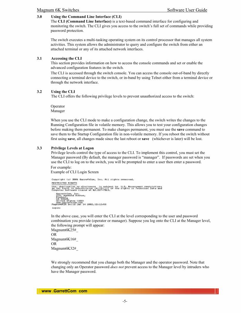
Privilege levels control the type of access to the CLI. To implement this control, you must set the Manager password (By default, the manager password is “manager”. If passwords are set when you use the CLI to log on to the switch, you will be prompted to enter a user then enter a password. For example: Example of CLI Login Screen
In the above case, you will enter the CLI at the level corresponding to the user and password combination you provide (operator or manager). Suppose you log onto the CLI at the Manager level, the following prompt will appear: Magnum6K25#_ OR Magnum6K16#_ OR Magnum6K32#_ We strongly recommend that you change both the Manager and the operator password. Note that changing only an Operator password does not prevent access to the Manager level by intruders who have the Manager password.

Magnum 6K Switches Software User Guide
www GarrettCom com..
-6-
3.3.1 Operator Privileges At the Operator level you can examine the current configuration and move between interfaces without being able to change the configuration. A ">" character delimits the Operator-level prompt. For example: Magnum6K25>_ (Example of the Operator prompt.)
3.3.2 Manager Privileges Manager privileges give you three additional levels of access: Manager, Global Configuration, and Context Configuration. A “#” character delimits any Manager prompt. For example: Magnum6K25#_ (Example of the Manager prompt.) Manager level: Provides all Operator level privileges plus the ability to perform system-level actions. The prompt for the Manager level contains only the system name and the “#” delimiter, as shown above. To select this level, enter the enable <manager> command at the Operator level prompt and enter the Manager password, when prompted. For example:
Magnum6K25> enable <Manager> (Enter enable at the Operator prompt.) Magnum6K25# _ (The Manager prompt.)
Global Configuration level: Provides all Operator and Manager level privileges, and enables you to make configuration changes to any of the switch’s software features. The prompt for the Global Configuration level includes the system IP, System Date, time etc.
Context Configuration level: Provides all Operator and Manager privileges, and enables you to make configuration changes in a specific context, such as one or more ports or a VLAN. The prompt for the Context Configuration level includes the system name and the selected context.
For example: Magnum6K25# configure vlan type=port OR Magnum6K25# vlan type=port Magnum6K25(port-vlan)##_ (The Configuration Prompt)
3.4 User Management
Using this module you can add, modify and delete user names and passwords. You can add 5 users maximum. Two privilege levels are available; Manager and Operator. Level 1 is meant for OPERATOR and Level 2 for MANAGER. For example, if you want to set up user name for basic monitoring capabilities then use lower number (Level 1).
Note: You can add more then one manager but total limit of users is five (including OPERATORS and MANAGERS).
3.4.1 CLI Commands To Add User Syntax: add user=<name> level=<number> Magnum6K25(user)##add user=Raj level=2
Enter User Password :****** Confirm New Password :****** In this example, User ‘Raj’ will be added with Manager privilege. To Delete User Syntax: delete user=<name> Magnum6K25(user)##delete user=Raj Confirm User Deletion(Y/N): Y User successfully deleted

Magnum 6K Switches Software User Guide
www GarrettCom com..
-7-
To modify Password Syntax: passwd user=<name> Magnum6K25(user)## passwd user=Raj Enter New Password :****** Confirm New Password :****** Password has been modified successfully To modify the Privilege Level Syntax: chlevel user=<name> level=<number> Magnum6K25(user)## chlevel user=Raj level=1 Access Permission Modified In this example, User ‘Raj’ has been modified with Operator privilege.
3.5 Listing Commands and Command Options
At any privilege level you can:
• List all of the commands available at that level • List the options for a specific command
Listing Commands Available at Any Privilege Level At a given privilege level you can execute the commands that level offers plus all of the commands available at preceding levels. For example, at the Operator level you can list and execute only the Operator level commands. However, at the Manager level you can list and execute the commands available at both the Operator and Manager levels. Privilege Level Example of Prompt and Permitted Operations
3.5.1 Operator Privilege
-View status and configuration information. -Perform connectivity tests. -Move from the Operator level to the Manager level using the ‘enable’ command. -Exit from the CLI interface and terminate the console session using the ‘logout’ command. For a list of available commands, enter ‘help’ at the prompt. For example, to view status and configuration information of the Operator Level use the show command: Magnum6K25> show <command>
3.5.2 Manager Privilege
At the Manager Level (Magnum6K25#) prompt you can perform system-level actions such as system control, configuration, monitoring, and diagnostic commands, plus any of the Operator-level commands. For a list of available commands, enter ‘help’ at the prompt. At the Configuration (Magnum6K25##) prompt you can execute configuration commands, plus all Operator and Manager commands. For a list of available commands, enter ‘help’ at the Context Configuration prompt.
3.5.3 Type "help" To List Available Commands. Typing the ‘help’ command lists the commands you can execute at the current privilege level. For example, typing ‘help’ at the Operator level produces this listing:

Magnum 6K Switches Software User Guide
www GarrettCom com..
-8-
Magnum6K25> help
Typing ‘help’ at the Manager level produces this listing Magnum6K25# help
3.5.4 Displaying CLI "Help" CLI Help provides four types of context-sensitive information:
• Command list with a brief summary of each command’s purpose. • Detailed information on how to use individual commands. • Command line verbosity with possible options. • Command usage of specific commands.
3.5.5 Displaying Help for an Individual Command.
You can display Help for any command that is available at the current context level by typing help then entering enough of the command string to identify the command. Syntax: help <command string> For example, to list the Help for the set time command at the Configuration privilege level type: Magnum6K25# help set time
3.5.6 Displaying Help for a particular command.
You can display the command usage of a specific command by typing the command and pressing enter.

Magnum 6K Switches Software User Guide
www GarrettCom com..
-9-
Syntax: <Command Name> <Enter>
3.5.7 Displaying Help with all possibilities.
You can display Help for all possible commands and options that are available by pressing the <TAB> key. Syntax: <TAB> Or <Command string> <TAB> Or <First character of the command> <TAB> For example, <TAB> will list the available commands in the particular privilege level: Magnum 6K25> <TAB> clear enable exit help logout ping set show telnet terminal walkmib whoami Magnum 6K25> s <TAB> set show Magnum 6K25# set <TAB> bootmode date daylight logsize password serial snmp stp time timeformat timeout timezone vlan
Magnum 6K Switches Software User Guide
www GarrettCom com..
-10-
4.0 Web Interface 4.1 Overview
• Optimize your network uptime by using the Alert Log and other diagnostic tools. • Make configuration changes to the switch. • Maintain security by configuring usernames and passwords.
This chapter covers the following: • General features. • System requirements for using the web browser interface. • Starting a web browser interface session. • Tasks for your first web browser interface session.
Creating usernames and passwords in the web browser interface. Getting access to online help for the web browser interface.
• Description of the web browser interface:
Overview window and tabs. Port Utilization and Status displays. Event Log and Event types.
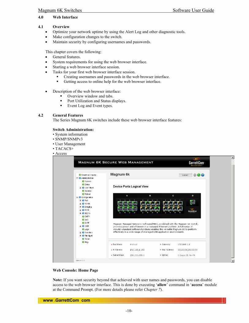
4.2 General Features
The Series Magnum 6K switches include these web browser interface features:
Switch Administration: • System information • SNMP/SNMPv3 • User Management • TACACS+ • Access
Web Console: Home Page Note: If you want security beyond that achieved with user names and passwords, you can disable access to the web browser interface. This is done by executing ‘allow’ command in ‘access’ module at the Command Prompt. (For more details please refer Chapter 7).

Magnum 6K Switches Software User Guide
www GarrettCom com..
-11-
Switch Configuration: • Ports
• Port Setting • Port Security • Port Mirroring
• VLAN • Port Vlan • Tag Vlan • GVRP
• Bridging • Aging • Address Table • ARP Table
• STP/RSTP • Bridge STP/RSTP • Port STP/RSTP • Link Loss Learn • S-Ring (Optional)
• 802.1x • SMTP • QoS • SNTP • IGMP • Logs
• Event Log • Statistics
• Port statistics • Log statistics
• Software/OS upload (File Management)
• TFTP • FTP
• Telnet • Ping
4.3 Session with the Switch
1. You can start a web browser session using a standalone web browser on a network connection from a PC or UNIX workstation: • Directly connected to your network • Connected through remote access to your network • Compatible with Netscape 4.x onwards and Microsoft Internet Explorer 5.x onwards.
2. Type the IP address (or DNS name) of the switch in the browser Location or Address field and press [Enter]. magnum6k25 or 6K25 or 6K16 or 6K32 [Enter] (example of a DNS-type name) 10.11.12.180 [Enter] (example of an IP address) If you are using a Domain Name Server (DNS), your device may have a name associated with it (for example, magnum6k25) that you can type in the Location or Address field instead of the IP address. Using DNS names typically improves browser performance. Note: See your network administrator for any name associated with the switch.

Magnum 6K Switches Software User Guide
www GarrettCom com..
-12-
4.4 User Management You may want to create both a username and password to create access security for your switch. There are two levels of access to the interface that can be controlled by setting user names and passwords: Operator: An Operator-level user name and password allows read-only access to most of the web browser interface, but prevents access to the Configuration. Manager: A Manager-level user name and password allows full read/write access to the web browser interface.
To Set the Device Passwords Window
4.4.1 To set the passwords
1. Go to Administration- User Management 2. Click in the appropriate box in the Passwords window and enter user names and passwords. You will be required to repeat the password strings in the confirmation boxes. 3. Click on [OK] to modify the user names and passwords. Note: Passwords you assign in the web browser interface will overwrite previous passwords assigned in the web browser interface, the Command Prompt, or the switch console. That is, the most recently assigned passwords are the switch’s passwords, regardless of which interface was used to assign the string.

Magnum 6K Switches Software User Guide
www GarrettCom com..
-13-
Example of the Login Window in the Web Browser Interface
The manager and operator passwords are used to control access to all switch interfaces. Once set, you will be prompted to supply the password every time you try to access the switch through any of its interfaces. The password you enter determines the capability you have during that session:
Entering the manager password gives you full read/write capabilities Entering the operator password gives you read and limited write capabilities.
Using the User Names If you also set user names in the web browser interface screen, you must supply the correct user name and access type for web browser interface access. If you loose a Password, contact [email protected]
Online Help for the Magnum 6K Web Browser Interface Online Help is available for the web browser interface. You can use it by clicking on the Help button in the navigation bar of the web browser interface screens. Context-sensitive help is provided with in the Help.
Support URL This is the site that the switch accesses when you click on the Support button on the web browser interface. The default URL is: http://www.garrettcom.com/techsupport which is the World Wide Web site for GarrettCom’s networking products. On that page you can get to support information regarding your switch, including white papers, operating system (OS) updates, and more. Note If you do not have an active connection to the World Wide Web, then online support for the web browser interface will not be available.
4.5 Status Reporting Features
Browser elements covered in this section include: • The Device View (Logical) • Port utilization and status • The Event log • The Status bar

Magnum 6K Switches Software User Guide
www GarrettCom com..
-14-
4.5.1 The Device View The Device view is the logical view of the front panel of the switch. The following figure identifies the various parts of the screen.
4.5.2 The Port Statistics
The Port Utilization and Status displays show an overview of the status of the switch and the amount of network activity on each port. The following figure shows a sample reading of the Port Utilization and Port Status.
4.5.3 Port Utilization
The Port Utilization bar graphs show the network traffic on the port with a breakdown of the packet types that have been detected (Multicast packets, Frames with CRC, Oversized Frames, and Jabber Frames). The Legend identifies traffic types.

Magnum 6K Switches Software User Guide
www GarrettCom com..
-15-
The Port Status indicators show a symbol for each port that indicates the general status of the port. There are four possible states: Port Connected – the port is enabled and is properly connected to an active network device, shows green in color. Port Not Connected – the port is enabled but is not connected to an active network device. A cable may not be connected to the port, or the device at the other end may be powered off or inoperable, or the cable or connected device could be faulty. Port Disabled – the port has been configured as disabled through the web browser interface, the switch console, or SNMP network management. Port Enabled – the port is enabled by default. (Read chapter “Monitoring and Analyzing Switch Operation” for more information.)
4.5.4 The Event Log
The web browser interface Event Log, shows a list of network occurrences, or alerts, that were detected by the switch. Typical alerts are Cold start, indicating that switch has been restarted, and Link up :port 6, indicating that port number 6 is being enabled.

Magnum 6K Switches Software User Guide
www GarrettCom com..
-16-
Each alert has the following fields of information:
• Date/Time – The date and time the event was received by the web browser interface. This value is shown in the format: DD-MM-YY HH:MM:SS AM/PM, for example, 01-08-2001 7:58:44 AM.
• Severity – It show the severity level of the event. There are five severity levels: Informational, Activity, Critical, Fatal and Debug.
• Description – A short narrative statement that describes the event. For example, “Vlan with this Vlan name already exists”.
Sorting the Alert Log Entries The alerts are sorted, by default, by the Date/Time field with the most recent alert listed at the top of the list. The second most recent alert is displayed below the top alert and so on. If alerts occurred at the same time, the simultaneous alerts are sorted by order in which they appear in the MIB. The alert field that is being used to sort the alert log is indicated by which column heading is in bold. See chapter “Troubleshooting” for more information on Event Log.
.

Magnum 6K Switches Software User Guide
www GarrettCom com..
-17-
5.0 Configuring IP Addressing, Interface Access, and System Information 5.1 Overview This chapter describes the switch configuration features available in the CLI and web browser interface. For help on how to use these interfaces, refer to: _ Chapter 3, “Using the Command Line Interface (CLI)” _ Chapter 4, Using the Magnum Web Browser Interface” Why Configure IP Addressing? In its factory default configuration, the switch operates as a multi port learning bridge with network connectivity provided by the ports on the switch. However, to enable specific management access and control through your network, you will need IP addressing Why Configure Interface Access and System Information? The interface access features in the switch operate properly by default. However, you can modify or disable access features to suit your particular needs. Similarly, you can choose to leave the system information parameters at their default settings. However, using these features can help you to more easily manage a group of devices across your network. 5.2 IP Configuration 5.2.1 IP Address and Subnet Mask Overview.
Configuring the switch with an IP address expands your ability to manage the switch and use its features. To configure IP addressing, use the CLI to manually configure the initial IP values.
5.2.2 IP Address and Subnet Mask.
By default, the switch is set to manual IP addressing. To arrange the manual IP addressing, use the CLI to configure the initial IP values. If you want to configure the IP automatically then enable the DHCP/Bootp server that has been set correctly with information to support the switch, and it will auto configure the IP. (Refer to “DHCP/Bootp Operation” for information on setting up automatic configuration from a server.). For information on how IP addressing affects switch performance, refer to “How IP Addressing Affects Switch Operation”.
5.2.3 Default Gateway Operation.
The default gateway is required for tasks such as reaching off-subnet destinations or forwarding traffic across multiple VLANs. The gateway value is the IP address of the next-hop gateway node for the switch which is used if the requested destination address is not on a local subnet/VLAN. If the switch does not have a manually-configured default gateway and DHCP/Bootp is configured, then the default gateway value provided by the DHCP or Bootp server will be used. If the switch has a manually configured default gateway, then the switch uses this gateway.
5.2.4 Configuring IP Address, Gateway, DHCP
Do one of the following: _ To set the bootmode parameter to Manual and then manually enter the IP address and subnet mask values you want for the switch. _ To use DHCP or Bootp, use the “set bootmode” command to ensure that the bootmode parameter is set to DHCP or Bootp (this enables the DHCP/Bootp), then refer to “DHCP/Bootp Operation”.
Syntax: set bootmode=<dhcp|bootp|manual> Magnum6K25# set bootmode=dhcp Save and restart the switch. It will fetch an IP address from the DHCP Server.
5.3 DHCP/Bootp Operation
5.3.1 Overview
DHCP/Bootp is used to provide configuration data from a DHCP or Bootp server to the switch. This data can be the IP address, subnet mask, and default gateway. With either DHCP or Bootp, the servers must be configured prior to the switch being connected to the network.

Magnum 6K Switches Software User Guide
www GarrettCom com..
-18-
5.3.2 The DHCP/Bootp Process Whenever the IP Config parameter in the switch is configured to DHCP/Bootp , or when the switch is rebooted with this configuration then follow the steps below:
5.3.3 Configuring IP Addressing 1.DHCP/Bootp requests are automatically broadcast on the local network. (The switch sends one type of request to which either a DHCP or Bootp server can respond.) 2. When a DHCP or Bootp server receives the request, it replies with a previously configured IP address and subnet mask for the switch. The switch also receives an IP Gateway address if the server has been configured to provide one. In the case of Bootp, the server must first be configured with an entry that has the MAC address of the switch. To determine the switch’s MAC address, use CLI command: Magnum6K25#show mac MAC Address: 00:20:06:25:00:11
Note If you manually configure a gateway on the switch, it will ignore any gateway address received via DHCP or Bootp. If the switch is initially configured for DHCP/Bootp operation, or if it is rebooted with this configuration, it immediately begins sending request packets on the network. If the switch does not receive a reply to its DHCP/Bootp requests, it continues to periodically send request packets, but with decreasing frequency. Thus, if a DHCP or Bootp server is not available or accessible to the switch when DHCP/Bootp is first configured, the switch may not immediately receive the desired configuration. After verifying that the server has become accessible to the switch, reboot the switch to re-start the process immediately.
5.3.4 DHCP Operation A significant difference between a DHCP configuration and a Bootp configuration is that an IP address assignment from a DHCP server is automatic. Depending on how the DHCP server is configured, the switch may receive an IP address that is temporarily leased from the DHCP. Periodically the switch may be required to renew its lease of the IP configuration. Thus, the IP addressing provided by the server may be different each time the switch reboots or renews its configuration from the server. However, you can fix the address assignment for the switch by doing either of the following: _ Configure the server to issue an “infinite” lease. _ Using the switch’s MAC address as an identifier, configure the server with a “Reservation” so that it will always assign the same IP address to the switch. For more information on either of these procedures, refer to the documentation provided with the DHCP server. For DHCP operation: • The entire scope of DHCP configuration has been updated on the appropriate DHCP server. • The necessary network connections are in place • A DHCP server is accessible from the switch
After you reconfigure or reboot the switch while in a network providing DHCP/Bootp service with DHCP/Bootp enabled, the switch does the following: _ Receives an IP address, _ Subnet mask, and _ Gateway IP address (if configured in the server)
5.3.5 Bootp Operation When a Bootp server receives a request, it searches its Bootp database for a record entry that matches the MAC address in the Bootp request from the switch. If a match is found, the configuration data in the associated database record is returned to the switch. For many UNIX systems, the Bootp database is contained in the /etc/bootptab file. In contrast to DHCP operation, Bootp configurations are always the same for a specific receiving device. That is, the Bootp server replies to a request with a configuration previously stored in the server and designated for the requesting device.
Magnum 6K Switches Software User Guide
www GarrettCom com..
-19-
5.3.6 Bootp Database Record Entries A minimal entry in the Bootp table file /etc/bootptab to update an IP address and subnet mask to the switch would be similar to this entry:
M6k25switch:\ ht=ether:\ ha=002006250065:\ ip=192.168.1.88:\ sm=255.255.255.0:\ gw=192.168.1.1:\ hn:\ vm=rfc1048 where: M6Kswitch is a user-defined symbolic name to help you find the correct section of the bootptab file. If you have multiple switches that will be using Bootp to get their IP configuration, you should use a unique symbolic name for each switch. ht is the “hardware type”. For the Magnum Managed Switches, set this to ether (for Ethernet). This tag must precede the ha tag. ha is the “hardware address”. Use the switch’s 12-digit MAC address. ip is the IP address to be assigned to the switch. sm is the subnet mask of the subnet in which the switch is installed. Note: The above Bootp table entry is a sample that will work for the Magnum Switches when the appropriate addresses and file names are used.
Network Preparations for Configuring DHCP/Bootp In its default configuration, the switch is configured for manual IP operation. DHCP/BootP can be enable. Syntax: set bootmode=<dhcp|bootp|manual> However, the DHCP/Bootp feature will not acquire IP addressing for the switch unless the following tasks have already been completed: For Bootp operation:
• A Bootp database record has already been entered into an appropriate Bootp server. • The necessary network connections are in place • The Bootp server is accessible from the switch
5.3.7 Globally Assigned IP Network Addresses If you intend to connect your network to other networks that use globally administered IP addresses, GarrettCom strongly recommends that you use IP addresses that have a network address assigned to you. There is a formal process for assigning unique IP addresses to networks worldwide. For more information please contact your internet service provider (ISP).
5.4 A Quick Start
If you just want to give the switch an IP address so that it can communicate on your network, or if you are not using VLANs, GarrettCom recommends that you use the CLI commands to quickly configure IP addressing. To do so, do one of the following: Enter the following command at the CLI Manager level prompt. Magnum6K25# ipconfig ip = <ipaddress> mask = <subnet-mask> dgw= <default-gateway> Syntax: show ipconfig Magnum6K25# show ipconfig IP Address : 192.168.1.25 Subnet Mask : 255.255.255.0 Default Gateway : 192.168.1.10 Note: In the factory-default configuration there is no IP addressing assigned to the switch.

Magnum 6K Switches Software User Guide
www GarrettCom com..
-20-
5.5 Interface Access: Console/Serial Link, Telnet Features In most cases, the default configuration is acceptable for standard operation. Note Basic switch security is through passwords. You can gain additional security using IP authorized managers. However if unauthorized access is gained to the switch through in-band (Telnet), then you can disallow in-band access (as described in this section) and install the switch in a locked environment. Feature Default Inactivity Time 10 Minutes Terminal Type VT-100 Baud Rate 38400 Flow Control None
5.5.1 Serial Port (Console)
User can change the serial (Console) parameters viz baud rate, data, parity, stop and flow control with in MNS-6K. Syntax: set serial [baud=<rate>] [data=<5|6|7|8>] [parity=<none|odd|even>] [stop=<1|1.5|2>] [flowctrl=<none|xonxoff] To see the current settings, Syntax: show serial Magnum6K25#show serial Baud Rate: 38400 Data : 8 Parity : No Parity Stop : 1
Flow Control : None 5.5.2 TELNET
The Telnet protocol is often thought of simply as a provider for remote logins to computer via the Internet. This was its original purpose although it can be used for many other purposes. It is best understood in the context of a user with a local computer accessing the local telnet program (known as the client program) to run a login session on a remote computer where his communication needs are handled by a telnet server program running on the remote computer. It should be emphasized that the telnet server can pass on the data it has received from the client to many other types of processes including a remote login server.
A user can telnet a remote host (Computer or switch) from the Magnum 6K.
syntax: telnet <ipaddress> [port=<port number>]
E.g. telnet 192.168.1.1 [port is optional]. The default port is 23.
We also have the Telnet Client on the Magnum 6K. Users can telnet the Magnum 6K from the host (Computer or switch) remotely. In other words users can manage the switch remotely. Note: (i) we have to have an IP configuration on the switch before starting the telnet
session. (ii) Once the Telnet session starts, the serial connection will be inactive. (iii) In the default configuration, inbound and outbound Telnet access is enabled.
To disable or enable Telnet access: Syntax: telnet <enable/disable> Magnum6K25 (access) ## telnet disable Disabling Access to Telnet
Magnum6K25 (access) ## telnet enable Enabling Access to Telnet

Magnum 6K Switches Software User Guide
www GarrettCom com..
-21-
5.6 Listing the Current System Information. 5.6.1 List the current system information settings.
Syntax: show setup This example shows the switch’s default console configuration.
and, Syntax: show sysconfig Syntax: show console
5.6.2 System Information
Configuring system information is optional, but recommended. System Name: Using a unique name helps you to identify individual devices in stacking environments and when using SNMPc, HP Open View or any other NMS software for Hubs & Switches. (For more details see chapter SNMP).
5.6.3 System Contact and Location:
This information is helpful for identifying the person administratively responsible for the switch and for identifying the locations of individual switches. Magnum6K25#snmp Magnum6K25(snmp)## Syntax: setvar [sysname|syscontact|syslocation]=<string> Magnum6K25(snmp)##setvar syslocation=Fremont System variable(s) set successfully (For more details see chapter SNMP).
5.7 Configure the Date and Time
The switch uses the date command to configure the date. Note that the CLI uses either a 12 or 24-hour clock scheme; that is, hour (hh) values from 1 p.m. to midnight are input either as 1 or 13. You can set the format with the help of the set time command. Syntax: set date year=<2000-2036> month=<1-12> day=<1-31> For example, to set the switch to 3:45 p.m. on October 1, 2001 in California USA input “GMT –08:00”: Magnum6K25# set timezone GMT=[+ or -] hour=<0-14> min=<0-59> Magnum6K25# set date year=<2001-2035> month=<1-12> day=<1-31> Note: Executing reboot resets the time and date to their default startup values.
5.7.1 SNTP Simple Network Time Protocol The SNTP protocol is used to allow network access to accurate clocks and other sources of time base information that is an adaptation of the Network Time Protocol (NTP) used to synchronize device clocks in the Internet. The SNTP client of the Magnum 6K has the ability to set the SNTP server IP address. The SNTP client synchronizes the time and date with the SNTP server. CLI Commands
Magnum6K25# sntp Magnum6K25(sntp)##
Syntax: setsntp server = <ipaddress> timeout = <1-10> retry = <1-3> E.g., Magnum6K25(sntp)## setsntp server = 204.65.129.201 timeout = 3 retry = 3

Magnum 6K Switches Software User Guide
www GarrettCom com..
-22-
User can also set the frequency for synchronization of time from SNTP Server. Syntax: sync [hour=<0-24>] [min=<0-59>] Once the IP address of SNTP assigned then enable the SNTP service. Magnum6K25(sntp)## sntp enable| SNTP is enabled. Note: If you do not have SNTP Server on your local network then you can use any public SNTP/NTP Server. Here are a few known public SNTP/NTP Servers. worf.ijs.si - 193.2.4.2 time.ijs.si - 193.2.4.6 time.nrc.ca - 132.246.168.164 ntp0.usno.navy.mil - 192.5.41.40
5.7.2 Time Zone The number of minutes your time zone location is to the West (+) or East (-) of Coordinated Universal Time (formerly GMT). The default 0 means no time zone is configured.
5.7.3 Zone and Daylight Time Rule. These commands:
• Set the time zone you want to use • Define the daylight time rule for keeping the correct time when
daylight-saving-time shifts occur. Syntax: set timezone GMT=[+ or -] hour=<0-14> min=<0-59> set timeformat format=<12|24> set daylight country=< country name> Note: For more details please read Appendix A.
5.8 CLI: Configuration commands
The Magnum 6K has the following CLI commands available for configuration management.
• Saveconf • Loadconf • Kill config (Hidden Command)
Note: These commands are available in ‘Manager’ privilege only.
5.8.1 To save the configuration
You can save the configuration as a binary file on the local console or FTP or TFTP Server using the ‘saveconf’ command
Syntax: saveconf mode=<serial|tftp|ftp> [<ipaddress>] [file=<name>] Magnum6K25# saveconf mode=serial file=6kconfig Note: File name is a user defined name.
5.8.2 To load or restore the configuration
You can load the configuration from the location you have saved the configuration e.g., the local console, FTP or TFTP Server using ‘loadconf’ command. Syntax: loadconf mode=<serial|tftp|ftp> [<ipaddress>] [file=<Name>] Magnum6K25# loadconf mode=serial file=6kconfig

Magnum 6K Switches Software User Guide
www GarrettCom com..
-23-
5.8.3 To erase the current configuration Syntax: kill config Note: This is a hidden command. It erases the current configuration and loads the factory default configuration. It is highly recommended to use this command only if you really need to erase the current configuration. Magnum6K25# kill config
Warning: Before erasing the current configuration using the ‘kill config’ command it is suggested that you save the current configuration using the ‘saveconf’ command. The ‘kill config’ command will erase the current configuration and load the default configuration values. The ‘kill config’ command will not erase or change any saved configuration settings in memory.
The ‘Kill config’ command asks for confirmation. If you are sure press ‘Y’, otherwise press ‘N’. Do you want to erase the configuration? [ 'Y' or 'N'] If you press ‘Y’, it displays a confirmation message Successfully erased configuration...Please reboot.
Note: Please restart the switch to get a default configuration. kill config’ will not erase the current configuration until or unless you restart the switch.
5.8.4 Summary (Steps)
1. Save the current configuration on local console or FTP or TFTP Server. Command: saveconf 2. Erase current configuration. Command: kill config 3. Hard boot the switch to get the factory default configuration.
5.9 Web: Configuring IP Addressing
You can use the web browser interface to access IP addressing only if the switch already has an IP address that is reachable through your network. 1. Click on the [Administration] on left bar. 2. Click on [System]. 3. If you need further information on using the web browser interface, click on [Help] to access the web-based help available for the 6K Switches.
5.10 How IP Addressing Affects Switch Operation Without an IP address and subnet mask compatible with your network, the switch can be managed only through a direct terminal device connection to the Console RS-232 port. You can use direct-connect console access to take advantage of features that do not depend on IP addressing. However, to realize the full performance capabilities Magnum 6K networking offers through the switch, configure the switch with an IP address and subnet mask compatible with your network. The following table lists the general features available only with a network-compatible IP address configured.
Features Not Available Without an IP Address
• Telnet access to CLI • Magnum Web Browser Interface • SNMP Network Management • SNTP Server Configuration • TFTP and FTP download of configurations and Software updates • Ping test

Magnum 6K Switches Software User Guide
www GarrettCom com..
-24-
6.0 Security Features 6.1 Manager and Operator passwords:
You can gain access and privileges for the command line through either the console port or through the network by using Telnet . The features described in this chapter enhance security controls against unauthorized access through the network.
6.2 Console access interface and the CLI. There are two levels of console access: Manager and Operator. For security, you can set a password on each of these levels.
6.2.1 Manager This level allows access to all console interface areas. Please change the default Manager Password to limit access of unauthorized people to the configuration area of the console interface.
6.2.2 Operator This level allows access to the Status, Event Log, and CLI levels but does not allow Configuration capabilities. On the Operator level, the Configuration Context, Download Application, and Reboot Switch option are not accessible.
6.3 To use password security: 1. Set a Manager password (and an Operator password, if applicable for your system). 2. Exit from the current console session. A Manager password will now be needed for full access to the console. Assuming that both a Manager password and an Operator password have been set, the level of access to the console interface will be determined by which password is entered in response to the prompt. The manager and operator passwords control access to the CLI. Note: Passwords are case-sensitive.
6.4 CLI: Setting Manager and Operator Passwords 6.4.1 Configuring Manager and Operator Passwords
This procedure prompts you to enter a password twice to help verify that you have correctly entered the desired characters. Syntax: set password Magnum6K25# set password Enter old password:******** Enter new password:********* Confirm password :********* Password changed successfully Note: Password must be 4-10 characters (For more details, please refer chapter 3)
6.5 Access Levels For each authorized user, the Manager and Operator have specific access levels (For Details, Please see Chapter 2).
6.6 Configuring and Monitoring Port Security
The port security feature can be used to block input to an Ethernet, Fast Ethernet, or Gigabit Ethernet port when the MAC (Media Control Address) of the station attempting to access the port is different from any of the MAC addresses specified for that port. In the event of security violation, the port can be configured to go into the disable mode or drop mode. The drop mode allows the user to configure the port to remain enabled during a security violation and drop only packets that are coming in from insecure hosts.
Magnum 6K Switches Software User Guide
www GarrettCom com..
-25-
Network security hinges on the ability to allow or deny access to network resources. The access control aspect of secure network services involves allowing or disallowing traffic between a private network and an external network (such as the Internet) based on information contained in packets, such as the IP address, MAC address, or content. One such technology is Access Control Lists (ACL). An ACL is a packet filtering mechanism that reads a packet and allows it to pass or discards it according to criteria set up by the system administrator Magnum 6K switches support the source MAC filtration in Port Security module.
6.6.1 Basic Operation
Default Port Security Operation: The default port security setting for each port is off. That is, any device can access a port without causing a security reaction. Intruder Protection: A port that detects an “intruder” blocks the intruding device or drops the packets from transmitting to the network through that port. General Operation for Port Security: On a per-port basis, you can set up security measures to block unauthorized devices and send notice of security violations. Once you have configured port security, you can then monitor the network for security violations through the Event Log. For any port, you can configure the following: Authorized (MAC) Addresses: Specify devices (MAC addresses) that are allowed to send inbound traffic through the port. This feature: • Closes the port to inbound traffic from any unauthorized devices that are connected to the port. • Provides the option for sending information to the log of a detected attempted security violation to a network management station and disables the port. Note: There is a limitation of 200 MAC addresses per port and 500 MAC addresses per Switch for Port Security.
6.6.2 Blocking Unauthorized Traffic Unless you configure the switch to disable a port or drop the packets when a security violation is detected, the switch security only blocks unauthorized traffic without disabling the port. This feature enables you to apply the security configuration to ports on which hubs, switches, or other devices are connected and maintain security while also maintaining network access to authorized users.
6.6.3 Planning For Port Security
1. Plan your port security configuration and monitoring according to the following: a. On which ports do you want to configure port security? b. Which devices (MAC addresses) are authorized on each port? c. For each port, what security actions do you want? (The switch automatically blocks intruder detected on that port from transmitting to the network.) The switch can be configured to (i) Send intrusion alarms to the event Log and (ii) Optionally disable the port on which the intrusion was detected. d. How do you want to learn of the security violation attempts the switch detects? You can use the Event Log (through the CLI show log command) to see the intrusion. 2. Use the CLI commands to configure port security operating and address controls.
6.7 CLI: Port Security Command Options and Operation Configuring Port Security
Syntax: configure port-security Magnum6K25# configure port-security OR port-security <enter> It will take you to the configuration mode to configure the port security. Magnum6K25(port-security)##

Magnum 6K Switches Software User Guide
www GarrettCom com..
-26-
Allow an Authorized Device to a Port. There are two ways to add authorized MAC addresses: Manual (CLI: allow) or Automatic (CLI: learn). Syntax: allow mac=<address|list|range> port=<num|list|range> To simply add a device (MAC address) to a port’s existing Authorized Addresses list, enter the port number with the mac-address parameter and the device’s MAC address. Magnum6K25(port-security)## allow mac=00:c1:00:7f:ec: 00 00:60:b0:88:9e:00 port=18 In above example, two authorized devices are allowed for port number 18. Ports can also learn the MAC addresses with the help of the following command. Syntax: learn port=<number-list> <enable|disable> Magnum6K25(port-security)## learn port=17,18 enable In the above example, Port 17 and 18 start learn the MAC addresses of connected devices. Note: 1. Only when the ACTION is set to NONE will the MAC ADDRESS be learned 2. Maximum 200 MAC addresses can be learned per port. To enable and disable Port Security Syntax: ps <enable|disable> Magnum6K25(port-security)## ps enable This command enables the port security and switch is now ready to learn the MAC addresses. To See the Authorized Devices Syntax: show port-security Magnum6K25# show port-security port=18 After executing the above command, the security configuration for port 18 would be: Port :18 Action :Disable Signal :Log Learn Mode :Enable MAC_Addresses: 00:c1:00:7f:ec:00 00:60:b0:88:9e:00 To see all the Ports
Syntax: show port-security
Magnum6K25# show port-security Status: Port-security Disabled Port Action Signal Learn_Mode Mac_Address 1 None None Disable None 2 None None Disable None 3 None None Disable None 4 None None Disable None 5 None None Disable None 6 None None Disable None 7 None None Disable None 8 None None Disable None 9 None None Disable None 10 None None Disable None 11 None None Disable None 12 None None Disable None 13 None None Disable None 14 None None Disable None 15 None None Disable None 16 None None Disable None 17 Drop Log Enable None

Magnum 6K Switches Software User Guide
www GarrettCom com..
-27-
18 Drop Log Enable00:c1:00:7f:ec:00 00:60:b0:88:9e:00 19 Drop Log Enable None 20 Drop Log Enable None 21 Drop Log Enable None 22 Drop Log Enable None 23 Disable Log Enable 00:e0:29:6c:a4:fd 24 Drop Log Enable None 25 None None Disable None Removing a Device from the “Authorized” List for a Port. This command option removes unwanted devices (MAC addresses) from the Authorized Addresses list. (An Authorized Address list is available for each port where Learn Mode is set to “Static” To use the CLI to remove a device that is no longer authorized: Example: suppose port 18 is configured as shown below and you want to remove 00c100-123456 from the Authorized Address list: Magnum6K25# show port-security port=18 Port :18 Action :Disable Signal :Log Learn Mode :Disable MAC_Addresses: 00:c1:00:7f:ec:00 00:60:b0:88:9e:00 The following command serves this purpose by removing 00:c1:00:7f:ec:00 Magnum6K25(port-security)## remove mac=00:c1:00:7f:ec:00 port=18 The above command sequence results in the following configuration for port 18: Magnum6K25# show port-security port=18 Port :18 Action :Disable Signal :Log Learn Mode :Disable MAC_Addresses:00:60:b0:88:9e:00 To Set Action Type of secured port Syntax: action port=<num|list|range> type=<none|disable|drop> User can set the action type (none, disable or drop) for un-authorized devices for secured ports. Magnum6K25(port-security)##action port=11 drop Port security Action type set to Drop on selected port(s)
To set signal type of secured port Syntax: signal port=<num|list|range> <none|log|trap|logandtrap> User can set the ytpe of signal (Log, Trap or Both) for un-authorized devices for secured ports. Magnum6K25(port-security)##signal port=11 logandtrap Port security Signal type set to Log and Trap on selected port(s)
6.8 Reading Intrusion Alerts and Resetting Alert Flags 6.8.1 Notice of Security Violations
When the switch detects an intrusion on a port, it sets an “alert flag” for that port and makes the intrusion information available as described below. When a security violation occurs on a port configured for Port Security, the switch logs the intruder activity in the event log. – The show log command displays the Intrusion Log and the Event Log with different options.
Magnum 6K Switches Software User Guide
www GarrettCom com..
-28-
6.8.2 How the Intrusion Log Operates When the switch detects an intrusion attempt on a port, it enters a record of this event in the event Log. The event Log lists the most recently detected security violation attempts. This gives you a history of past intrusion attempts also. Example: S Date Time Log Description A 01-01-2001 12:05:52 AM PS:INTRUDER 00:e0:29:6c:a4:fd@port19, packet dropped A 01-01-2001 12:07:04 AM PS:INTRUDER 00:50:0f:02:33:b6@port17, packet dropped A 01-01-2001 12:07:16 AM PS:INTRUDER 00:e0:29:2a:f0:3a@port17, packet dropped A 01-01-2001 12:07:16 AM PS:INTRUDER 00:01:03:e2:27:89@port17, packet dropped A 01-01-2001 12:07:30 AM PS:INTRUDER 00:e0:29:08:d7:e9@port17, packet dropped A 01-01-2001 12:07:32 AM PS:INTRUDER 00:10:dc:6e:52:95@port17, packet dropped A 01-01-2001 12:07:34 AM PS:INTRUDER 00:e0:29:08:d6:43@port17, packet dropped The above is an example of Multiple Intrusion Log Entries for the Same Port The log shows the most recent intrusion at the top of the listing. Instead, if the log is filled when the switch detects a new intrusion, the oldest entry is dropped off the listing and the newest entry appears at the top of the listing.
6.8.3 CLI: Checking for Intrusions, Listing Intrusion Alerts
The following commands display port status including, whether there are intrusion alerts for any port(s), a list of the intrusions, and which specific ports had the intrusions. Magnum6K25# show log S Date Time Log Description A 01-01-2001 12:05:18 AM PS:INTRUDER 00:50:0f:02:33:b6@port17, packet dropped A 01-01-2001 12:05:26 AM PS:INTRUDER 00:02:b3:1d:05:dc@port17, packet dropped A 01-01-2001 12:05:36 AM PS:INTRUDER 00:01:03:e2:27:89@port17, packet dropped A 01-01-2001 12:05:40 AM PS:INTRUDER 00:e0:29:11:1b:af@port17, packet dropped A 01-01-2001 12:05:44 AM PS:INTRUDER 00:02:b3:64:d8:cf@port17, packet dropped A 01-01-2001 12:05:44 AM PS:INTRUDER 00:e0:29:09:5d:be@port17, packet dropped A 01-01-2001 12:05:48 AM PS:INTRUDER 00:02:b3:08:d2:22@port17, packet dropped A 01-01-2001 12:05:48 AM PS:INTRUDER 00:e0:29:2a:f0:3a@port17, packet dropped A 01-01-2001 12:05:56 AM PS:INTRUDER 00:10:dc:40:57:95@port17, packet dropped A 01-01-2001 12:06:02 AM PS:port 18 disabled, INTRUDER 00:e0:29:2a:f1:bd This log shows the intrusion at the port 17 and 18. You can always clear the log with clear command. Magnum6K25# clear log It clears the complete log. You can also clear the specific part of the Log. Syntax: clear log <informational|debug|activity|critical|fatal> Magnum6K25# clear log activity It clears the ‘activity’ log only.
6.9 Web: Viewing and Configuring Port Security In the web browser interface: 1. Click on the [Configuration] 2. Click on [Port]. 3. Click on [Security]. 4. Click on [Status] to enable it. 5. Click on any specific port to set ‘Signal’, ‘Action’ and ‘Learn’ status. 6. After you make the desired changes, click on [OK] button. 7. Click [Save] to save the configuration.
6.10 SSL (Secure Sockets Layer) Magnum 6K switches provide remote management through Telnet and Web in clear text. In other words, Telnet protocol negotiations as well as HTML over HTTP protocol negotiations that are sent to and from the 6K switches are not encrypted and are vulnerable to attacks from malicious sources. The MNS-6K Security Package (Rel2.7.1 onwards) resolved this issue. This package provides Secure
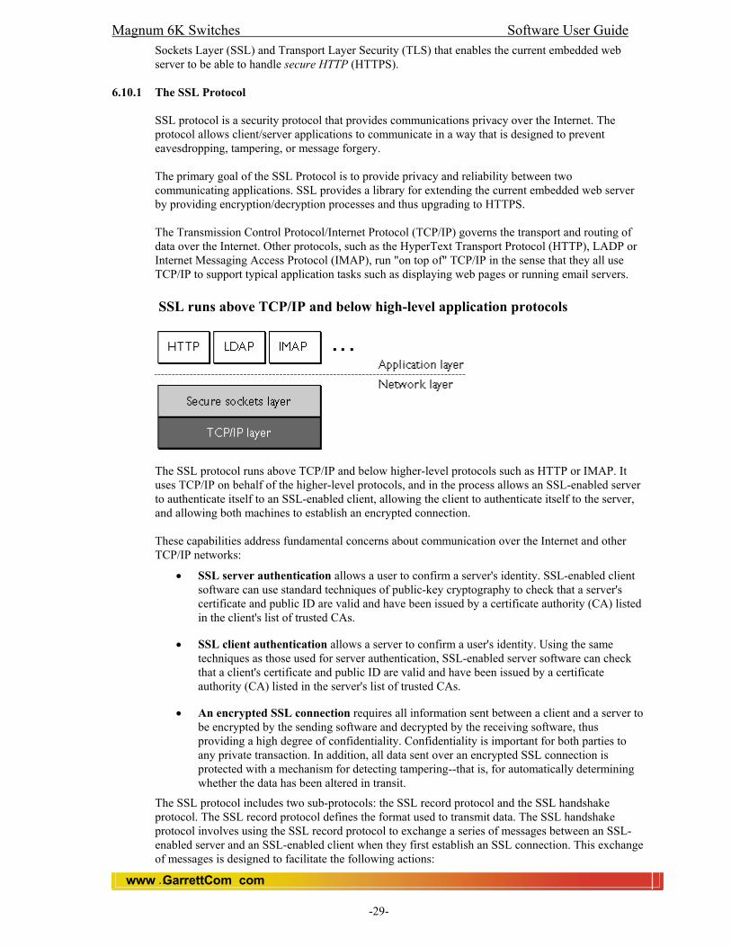
Magnum 6K Switches Software User Guide
www GarrettCom com..
-29-
Sockets Layer (SSL) and Transport Layer Security (TLS) that enables the current embedded web server to be able to handle secure HTTP (HTTPS).
6.10.1 The SSL Protocol SSL protocol is a security protocol that provides communications privacy over the Internet. The protocol allows client/server applications to communicate in a way that is designed to prevent eavesdropping, tampering, or message forgery. The primary goal of the SSL Protocol is to provide privacy and reliability between two communicating applications. SSL provides a library for extending the current embedded web server by providing encryption/decryption processes and thus upgrading to HTTPS. The Transmission Control Protocol/Internet Protocol (TCP/IP) governs the transport and routing of data over the Internet. Other protocols, such as the HyperText Transport Protocol (HTTP), LADP or Internet Messaging Access Protocol (IMAP), run "on top of" TCP/IP in the sense that they all use TCP/IP to support typical application tasks such as displaying web pages or running email servers. SSL runs above TCP/IP and below high-level application protocols
The SSL protocol runs above TCP/IP and below higher-level protocols such as HTTP or IMAP. It uses TCP/IP on behalf of the higher-level protocols, and in the process allows an SSL-enabled server to authenticate itself to an SSL-enabled client, allowing the client to authenticate itself to the server, and allowing both machines to establish an encrypted connection. These capabilities address fundamental concerns about communication over the Internet and other TCP/IP networks:
• SSL server authentication allows a user to confirm a server's identity. SSL-enabled client software can use standard techniques of public-key cryptography to check that a server's certificate and public ID are valid and have been issued by a certificate authority (CA) listed in the client's list of trusted CAs.
• SSL client authentication allows a server to confirm a user's identity. Using the same techniques as those used for server authentication, SSL-enabled server software can check that a client's certificate and public ID are valid and have been issued by a certificate authority (CA) listed in the server's list of trusted CAs.
• An encrypted SSL connection requires all information sent between a client and a server to be encrypted by the sending software and decrypted by the receiving software, thus providing a high degree of confidentiality. Confidentiality is important for both parties to any private transaction. In addition, all data sent over an encrypted SSL connection is protected with a mechanism for detecting tampering--that is, for automatically determining whether the data has been altered in transit.
The SSL protocol includes two sub-protocols: the SSL record protocol and the SSL handshake protocol. The SSL record protocol defines the format used to transmit data. The SSL handshake protocol involves using the SSL record protocol to exchange a series of messages between an SSL-enabled server and an SSL-enabled client when they first establish an SSL connection. This exchange of messages is designed to facilitate the following actions:

Magnum 6K Switches Software User Guide
www GarrettCom com..
-30-
• Authenticate the server to the client.
• Allow the client and server to select the cryptographic algorithms, or ciphers, that they both support.
• Optionally authenticate the client to the server.
• Use public-key encryption techniques to generate shared secrets.
• Establish an encrypted SSL connection.
6.10.2 Ciphers Used with SSL
The SSL protocol supports the use of a variety of different cryptographic algorithms, or ciphers, for use in operations such as authenticating the server and client to each other, transmitting certificates, and establishing session keys. Clients and servers may support different cipher suites, or sets of ciphers, depending on factors such as the version of SSL they support, company policies regarding acceptable encryption strength, and government restrictions on export of SSL-enabled software. Among its other functions, the SSL handshake protocol determines how the server and client negotiate which cipher suites they will use to authenticate each other, to transmit certificates, and to establish session keys. The cipher suite descriptions that follow refer to these algorithms:
• DES. Data Encryption Standard, an encryption algorithm used by the U.S. Government.
• DSA. Digital Signature Algorithm, part of the digital authentication standard used by the U.S. Government.
• KEA. Key Exchange Algorithm, an algorithm used for key exchange by the U.S. Government.
• MD2, MD4 and MD5. Message Digest algorithm.
• RC2, RC4 and RC5. Rivest encryption ciphers developed for RSA Data Security.
• RSA. A public-key algorithm for both encryption and authentication. RSA key exchange. A key-exchange algorithm for SSL based on the RSA algorithm.
• SHA-1. Secure Hash Algorithm, a hash function used by the U.S. Government.
• Blowfish
Key-exchange algorithms like RSA key exchange govern the way in which the server and client determine the symmetric keys they will both use during an SSL session. The most commonly used SSL cipher suites use RSA key exchange. The SSL 2.0 and SSL 3.0 (TLS 1.0) protocols support overlapping sets of cipher suites. Administrators can enable or disable any of the supported cipher suites for both clients and servers. When a particular client and server exchange information during the SSL handshake, they identify the strongest enabled cipher suites they have in common and use those for the SSL session. However, since 40-bit ciphers can be broken relatively quickly, administrators who are concerned about eavesdropping and whose user communities can legally use stronger ciphers should disable the 40-bit ciphers.
6.10.3 CLI Global Features
Magnum 6K Switches Software User Guide
www GarrettCom com..
-31-
• Users are able to enable/disable SSL extensions for Web Management. When turned on,
browser clients will have to communicate with the switch through HTTPS protocol instead of HTTP protocol.
• When Web Management is disabled, SSL is also disabled regardless of whether SSL function is enabled or disabled.
Note: SSL security can be disabled or enabled through Access module. By default it is enabled. Magnum6K25#access Magnum6K25(access)## Syntax: ssl <enable|disable> Magnum6K25(access)## ssl enable SSL is enabled. To see the status of SSL and Web Syntax: show ssl Magnum6K25# show ssl SSL/TLS is enabled. Syntax: show web Magnum6K25# show web HTTP is enabled. Current HTTP type is secure. If SSL is disabled, Magnum6K25#show web HTTP is enabled. Current HTTP type is unsecured.
Magnum 6K Switches Software User Guide
www GarrettCom com..
-32-
7.0 Using Authorized IP Managers to Protect Against Unauthorized Access 7.1 Authorized IP Manager Features
This feature enables you to enhance security on the switch by using IP addresses to authorize which stations (PCs or workstations) can access the switch. Thus, having the correct passwords is not sufficient for accessing the switch through the network unless the station attempting access is also included in the switch’s Authorized IP Managers configuration. Access controls cover: Telnet (CLI ) SNMP (network management) Web (Web Interface) Up to 25 authorized manager addresses, where each address applies to either a single management station or a group of stations Note This feature does not protect access to the switch through a modem or direct connection to the Console (RS-232) port. Also, if the IP address assigned to an authorized management station is configured in another station, the other station can gain management access to the switch even though a duplicate IP address condition exists. For these reasons, you should enhance your network’s security by keeping physical access to the switch restricted to authorized personnel, using the password features built into the switch, and preventing unauthorized access to data on your management stations.
7.2 Access Levels
For each authorized manager address, you can configure either of these access levels: 7.2.1 Authorizing Single Stations:
The table entry authorizes a single management station to have IP access to the switch. To use this method, just enter the IP address of an authorized management station in the Authorized Manager IP column, and leave the IP Mask set to 255.255.255.255. This is the easiest way to use the Authorized Managers feature.
7.2.2 Authorizing Multiple Stations:
The table entry uses the IP Mask to authorize access to the switch from a defined group of stations. This is useful if you want to easily authorize several stations to have access to the switch without typing in an entry for every station. All stations in the group are defined by the one Authorized Manager IP table entry and its associated IP mask and will have the same access level.
To configure the switch for authorized manager access, enter the appropriate Authorized Manager IP value and specify an IP Mask. The IP Mask determines how the Authorized Manager IP value is used for allowing or denying access to the switch by a management station.
7.3 Overview of IP Mask Operation
The default IP Mask is 255.255.255.255 and allows switch access only to a station having an IP address that is identical to the Authorized Manager IP parameter value. (“255” in an octet of the mask means that only the exact value in the corresponding octet of the Authorized Manager IP parameter is allowed in the IP address of an authorized management station.) However, you can alter the mask and the Authorized Manager IP parameter to specify ranges of authorized IP addresses. For example, a mask of 255.255.255.0 and any value for the Authorized Manager IP parameter allows a range of 0 through 255 in the 4th octet of the authorized IP address. This enables a block of up to 254 IP addresses for IP management access (excluding 0 for the network and 255 for broadcasts). A mask of 255.255.255.252 uses the 4th octet of a given Authorized Manager IP address to authorize four IP addresses (252,253,254,and 255) for management station access.
Note The IP Mask is a method for recognizing whether a given IP address is authorized for management access to the switch. This mask serves a different purpose than IP subnet masks and is applied in a different manner.

Magnum 6K Switches Software User Guide
www GarrettCom com..
-33-
7.4 CLI: Viewing and Configuring Authorized IP Managers
Listing the Switch’s Current Authorized IP Manager(s) Use the show ip-access command to list IP stations authorized to access the switch. For example:
Example of the Show IP Authorized-Manager Display The above example shows an Authorized IP Manager List that allows stations to access the switch for a specific service.
Magnum6K25#access <enter> Magnum6K25(access)## Configuring IP Authorized Managers for the Switch Syntax: allow ip=<ipaddress> mask=<netmask> service=<name|list> To Authorize Manager Access. This command authorizes access for any station having an IP address of 10.28.227.0 through 10.28.227.255for Telnet service: Magnum6K25(access)## allow ip=10.28.227.101 mask = 255.255.255.0 service=telnet Similarly, the next command authorizes access for any station having an IP address of 10.28.227.101 through 103 for snmp service: Magnum6K25(access)##allow ip=10.28.227.101 mask=255.255.255.252 service=snmp,telnet
You can deny a service(s) for a specific IP/Net mask also as shown below. Syntax: deny ip=<ipaddress> mask=<netmask> service=<name|list> Magnum6K25(access)## deny ip=10.28.227.101 mask = 255.255.255.0 service=telnet To Edit an Existing Access Entry. To change the mask or access level for an existing entry, use the entry’s IP address and enter the new value(s). Magnum6K25(access)## deny ip=10.28.227.101 mask = 255.255.255.0 service=web The above command replaces the existing mask and access level for IP address 10.28.227.101 with 255.255.255.0 and web denied service. Magnum6K25(access)## allow ip=10.28.227.101 mask = 255.255.0.0 service=web The above command replaces the existing mask and access level for IP address 10.28.227.101 with 255.255.0.0 and allowed web service. User can also remove a specific entry or all the entries using ‘remove’ command Syntax: remove ip=<ipaddress> mask=<netmask> Magnum6K25(access)##remove ip=10.28.227.101 mask=255.255.255.0 Access entry removed
To remove all the entries
Syntax: removeall Magnum6K25(access)##removeall Do you want to remove all Access Entries? [ 'Y' or 'N'] Y All access entries are removed
7.5 Building IP Masks The IP Mask parameter controls how the switch uses an Authorized Manager IP value to recognize the IP addresses of authorized manager stations on your network.

Magnum 6K Switches Software User Guide
www GarrettCom com..
-34-
7.5.1 Configuring One Station Per Authorized Manager IP Entry
This is the easiest way to apply a mask. If you have ten or fewer management and/or operator stations, you can configure them quickly by simply adding the address of each to the Authorized Manager IP list with 255.255.255.255 for the corresponding mask. For example, if you configure an IP address of 10.28.227.125 with an IP mask of 255.255.255.255, only a station having an IP address of 10.28.227.125 has management access to the switch.
1st Octet 2nd Octet 3rd Octet 4th Octet
Device Access
IP Mask Authorized Manager IP
255 255 255 255 10 28 227 125
The “255” in each octet of the mask specifies that only the exact value in that octet of the corresponding IP address is allowed. This mask allows management access only to a station having an IP address of 10.28.227.125.
Table: Analysis of IP Mask for Single-Station Entries
7.5.2 Configuring Multiple Stations Per Authorized Manager IP
The mask determines whether the IP address of a station on the network meets the criteria you specify. That is, for a given Authorized Manager entry, the switch applies the IP mask to the IP address you specify to determine a range of authorized IP addresses for management access. As described above, that range can be as small as one IP address (if 255 is set for all octets in the mask), or can include multiple IP addresses (if one or more octets in the mask are set to less than 255).
If a bit in an octet of the mask is “on” (set to 1), then the corresponding bit in the IP address of a potentially authorized station must match the same bit in the IP address you entered in the Authorized Manager IP list. Conversely, if a bit in an octet of the mask is “off” (set to 0), then the corresponding bit in the IP address of a potentially authorized station on the network does not have to match its counterpart in the IP address you entered in the Authorized Manager IP list. Thus, in the example shown above, a “255” in an IP Mask octet (all bits in the octet are “on”) means only one value is allowed for that octet—the value you specify in the corresponding octet of the Authorized Manager IP list. A “0” (all bits in the octet are “off”) means that any value from 0 to 255 is allowed in the corresponding octet in the IP address of an authorized station. You can also specify a series of values that are a subset of the 0-255 range by using a value that is greater than 0, but less than 255.
1st Octet 2nd Octet 3rd Octet 4th Octet
Device Access
IP Mask Authorized Manager IP
255 255 0 255 10 33 248 1
This combination specifies an authorized IP address of 10.33.xxx.1. It could be applied, for example, to a sub netted network where each subnet is defined by the third octet and includes a management station defined by the value of “1” in the fourth octet of the station’s IP address.
IP Mask Authorized Manager IP
255 238 0 255 10 247 100 195
Allows 230, 231, 246, and 247 in the 2nd octet, and 194, 195, 198, 199 in the 4th octet.
Table: Analysis of IP Mask for Multiple-Station Entries
NOTE: User can set maximum 25 rules (Allow/Deny). 26th rule will overwrite the first rule.

Magnum 6K Switches Software User Guide
www GarrettCom com..
-35-
7.6 Operating and Troubleshooting Notes: 7.6.1 Network Security Precautions:
You can enhance your network’s security by keeping physical access to the switch restricted to authorized personnel, using the password features built into the switch, and preventing unauthorized access to data on your management stations.
Modem and Direct Console Access: Configuring authorized IP manager does not protect against access to the switch through a modem or direct Console (RS-232) port connection.
7.6.2 Duplicate IP Addresses:
If the IP address configured in an authorized management station is also configured in another station, the other station can gain management access to the switch even though a duplicate IP address condition exists.
7.6.3 Web Proxy Servers:
If you use the web browser interface to access the switch from an authorized IP manager station, it is recommended that you avoid the use of a web proxy server in the path between the station and the switch. This is because switch access through a web proxy server requires that you first add the web proxy server to the Authorized Manager IP list. This reduces security by opening switch access to anyone who uses the web proxy server. The following two options outline how to eliminate a web proxy server from the path between a station and the switch: Even if you need proxy server access enabled in order to use other applications, you can still eliminate proxy service for web access to the switch. To do so, add the IP address or DNS name of the switch to the non-proxy, or “Exceptions” list in the web browser interface you are using on the authorized station. (e.g. in Microsoft Explorer go to tools, internet options, connections, lan settings, use a proxy server check, and advanced and enter it there). If you don’t need proxy server access at all on the authorized station, then just disable the proxy server feature in the station’s web browser interface.
7.6.4 Global Access
User can authorize the services globally. Here is the list of commands. snmp <enable|disable> dhcp <enable|disable> telnet <enable|disable> web <enable|disable> ssl <enable|disable> For example, Magnum6K25(access)##snmp disable It disables the SNMP Access to everyone.
7.7 Web: Viewing and Configuring Global Access Information
In the web browser interface: 1. Click on the [Administration] 2. Click on [Access Ctrl]. 4. Click on [Add] button. 5. After you make the desired changes, click on [OK] button. 6. Click [Save] to save the configuration.
7.7.1 Web: Viewing and Configuring System Information
In the web browser interface: 1. Click on the [Administration] 2. Click on [System]. 4. Click on [Modify] button. 5. After you make the desired changes, click on [OK] button. 6. Click [Save] to save the configuration.

Magnum 6K Switches Software User Guide
www GarrettCom com..
-36-
8.0 SNMP: Configuration for Network Management Applications
This chapter includes: • An overview of SNMP management for the switch. • SNMPv1, v2 and v3 support. • Bitview and Hubview through SNMPc. • Configuring the Series 6K switch for:
• SNMP management • SNMP Communities • Traps Configuration
• Information on advanced management through RMON To implement SNMP management, you must configure the switch with an appropriate IP address.
8.1 Overview
You can manage the switch via SNMP from a network management station. For this purpose, GarrettCom recommends the SNMPc, an easy-to-install and use network management platform that runs on Windows based PC’s. It uses the SNMP and RMON agents statistical sampling software that is included in the switch to provide powerful, but easy-to-use traffic monitoring and network activity analysis tools.
8.2 SNMP v1, v2 and v3 Magnum 6K switches support all three versions of SNMP viz SNMP v1, v2 and v3. User can switch between version 1 and version 3. (For details, please read section: SNMPv3) Note: SNMPv3 supports all three versions.
8.3 BitView and HubView The BitView and HubView can be seen through SNMPc (Management PC Software). Magnum6K’s that have BitView and HubView definitions can be managed graphically. BitView displays a bitmap image that matches the faceplate of the device, whereas HubView is a more generic view that shows the layout of the device, but always uses the same picture elements. BitView is functionally similar to HubView, but displays a more realistic image of supported devices. Generally, all the LEDs and other graphical elements available on the device front panel can be displayed with BitView. As with HubView, you can select a device slot or port, and then a menu to operate on the selected item.
Magnum6K25: Bitview

Magnum 6K Switches Software User Guide
www GarrettCom com..
-37-
Magnum6K25: Hubview
Magnum6K16: Bitview
Magnum6K32: Bitview 8.4 SNMP Management Features
SNMP management features on the switch include: SNMP version 1 Security via configuration of SNMP communities Event reporting via SNMP Managing the switch with an SNMP network management tool Supported Standard MIBs include: • SNMP MIB-II (RFC 1213) • Bridge MIB (RFC 1493) ifGeneralGroup, ifRcvAddressGroup, ifStackGroup • RMON MIB (RFC 1757) • RMON: groups 1, 2, 3, and 9 (Statistics, Events, Alarms, and History) • Version 1 traps (Warm Start, Cold Start, Link Up, Link Down, Authentication Failure, Rising
Alarm, Falling Alarm)

Magnum 6K Switches Software User Guide
www GarrettCom com..
-38-
• SNMPv3 RFCs (Please see SNMPv3 section for details) • GarrettCom Proprietary MIB
8.5 Configuring for SNMP Access to the Switch SNMP access requires an IP address and subnet mask configured on the switch. In other words, Network stacks should be configured with an IP address and subnet mask. Once an IP address has been configured, we can follow the same steps as configuring the CLI (see CLI section 6.5) to configure the SNMP Access. To authenticate the SNMP Manager station, you need to add the IP Address of the Manager station. This is a security feature of 6K Switches to authenticate the SNMP console station. Go to SNMP configuration mode. (i.e., Magnum6K25(SNMP)##) Magnum6K25# snmp <enter> Magnum6K25(SNMP)## Syntax: mgrip <add|delete> ip=<ipaddress> Note: If SNMP console is not added to the 6K switch, then user will not be able to access the SNMP agent. To configure and add the appropriate traps please see the CLI section of this chapter.
8.6 CLI: Viewing and Configuring Community Names 8.6.1 Listing Community Names
This command lists the data for currently configured SNMP community names. Syntax: show snmp Magnum6K25# show snmp This example lists the data for all communities in a switch; that is, both the default "public" community name and another community named "private". The configured community values are SNMP CONFIGURATION INFORMATION -------------------------------------------------------- SNMP Get Community Name : public SNMP Set Community Name : private SNMP Trap Community Name : public AuthenTrapsEnableFlag : enabled SNMP Access Status : enabled SNMP MANAGERS INFO ---------------------------------- SNMP TRAP STATIONS INFO ---------------------------------------- SNMP Manager and Traps are not yet configured.
8.7 Configuring Community Names and Values If you do not specify restricted or unrestricted for the read/write MIB access, the switch automatically restricts the community to read access for the MIB.
8.7.1 Adding SNMP Communities in the Switch The following SNMP command add new SNMP communities:
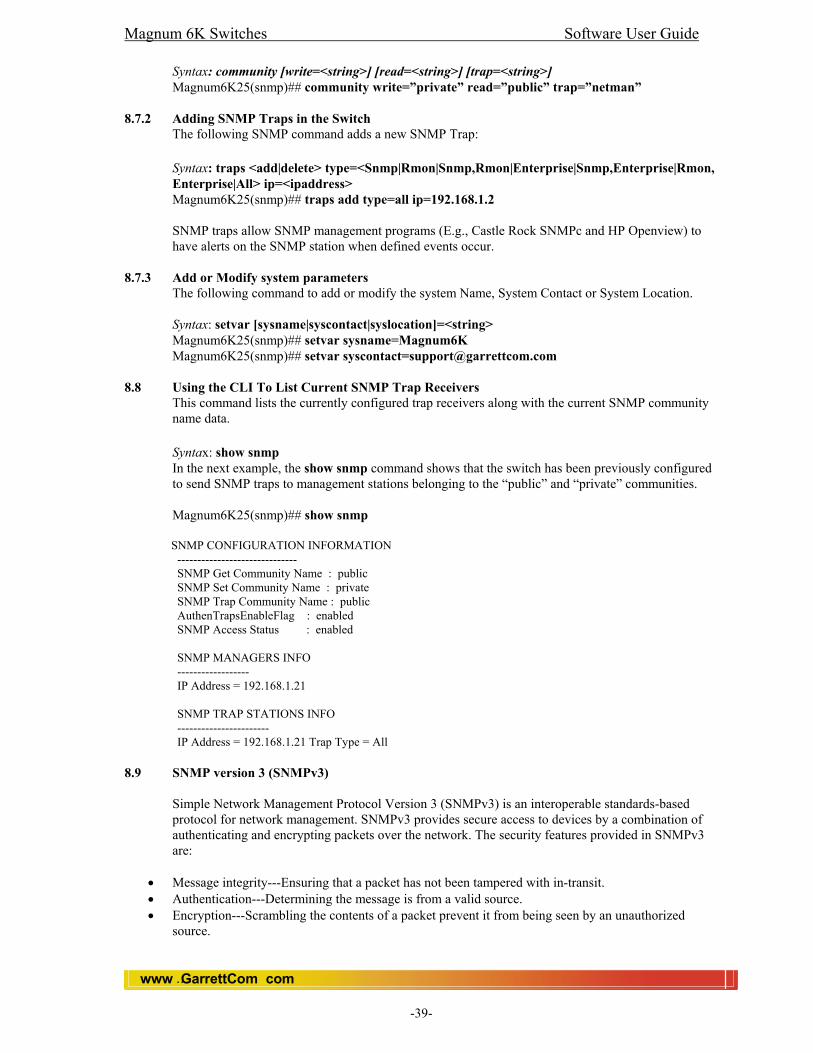
Magnum 6K Switches Software User Guide
www GarrettCom com..
-39-
Syntax: community [write=<string>] [read=<string>] [trap=<string>] Magnum6K25(snmp)## community write=”private” read=”public” trap=”netman”
8.7.2 Adding SNMP Traps in the Switch
The following SNMP command adds a new SNMP Trap: Syntax: traps <add|delete> type=<Snmp|Rmon|Snmp,Rmon|Enterprise|Snmp,Enterprise|Rmon, Enterprise|All> ip=<ipaddress> Magnum6K25(snmp)## traps add type=all ip=192.168.1.2 SNMP traps allow SNMP management programs (E.g., Castle Rock SNMPc and HP Openview) to have alerts on the SNMP station when defined events occur.
8.7.3 Add or Modify system parameters The following command to add or modify the system Name, System Contact or System Location.
Syntax: setvar [sysname|syscontact|syslocation]=<string> Magnum6K25(snmp)## setvar sysname=Magnum6K Magnum6K25(snmp)## setvar [email protected]
8.8 Using the CLI To List Current SNMP Trap Receivers This command lists the currently configured trap receivers along with the current SNMP community name data. Syntax: show snmp In the next example, the show snmp command shows that the switch has been previously configured to send SNMP traps to management stations belonging to the “public” and “private” communities. Magnum6K25(snmp)## show snmp SNMP CONFIGURATION INFORMATION ------------------------------ SNMP Get Community Name : public SNMP Set Community Name : private SNMP Trap Community Name : public AuthenTrapsEnableFlag : enabled SNMP Access Status : enabled SNMP MANAGERS INFO ------------------ IP Address = 192.168.1.21 SNMP TRAP STATIONS INFO ----------------------- IP Address = 192.168.1.21 Trap Type = All
8.9 SNMP version 3 (SNMPv3)
Simple Network Management Protocol Version 3 (SNMPv3) is an interoperable standards-based protocol for network management. SNMPv3 provides secure access to devices by a combination of authenticating and encrypting packets over the network. The security features provided in SNMPv3 are:
• Message integrity---Ensuring that a packet has not been tampered with in-transit. • Authentication---Determining the message is from a valid source. • Encryption---Scrambling the contents of a packet prevent it from being seen by an unauthorized
source.

Magnum 6K Switches Software User Guide
www GarrettCom com..
-40-
SNMPv3 provides for both security models and security levels. A security model is an authentication strategy that is set up for a user and the group in which the user resides. A security level is the permitted level of security within a security model. A combination of a security model and a security level will determine which security mechanism is employed when handling an SNMP packet. Three security models are available: SNMPv1, SNMPv2c, and SNMPv3. Table below identify what the combinations of security models and levels mean:
Table: SNMP Security Models and Levels
Model
Level Authentication Encryption
What Happens
v1 noAuthNoPriv
Community String
No Uses a community string match for authentication.
v2c noAuthNoPriv
Community String
No Uses a community string match for authentication.
v3 noAuthNoPriv
Username No Uses a username match for authentication.
v3 authNoPriv MD5 No Provides authentication based on the HMAC-MD5 or HMAC-SHA algorithms.
v3 authPriv MD5 DES Provides authentication based on the HMAC-MD5 or HMAC-SHA algorithms. Provides DES 56-bit encryption in addition to authentication based on the CBC-DES (DES-56) stand
Note the following about SNMPv3 objects: • Each user belongs to a group. • A group defines the access policy for a set of users. • An access policy is what SNMP objects can be accessed for reading, and writing. • A group determines the list of notifications its users can receive. • A group also defines the security model and security level for its users.
8.9.1 Benefits
• Data can be collected securely from SNMP devices without fear of the data being tampered with or corrupted.
• Confidential information, for example, SNMP Set command packets that change a router's configuration, can be encrypted to prevent its contents from being exposed on the network.
8.9.2 List of Terms authentication---The process of ensuring message integrity and protection against message replays. It includes both data integrity and data origin authentication. authoritative SNMP engine---One of the SNMP copies involved in network communication designated to be the allowed SNMP engine to protect against message replay, delay, and redirection. The security keys used for authenticating and encrypting SNMPv3 packets are generated as a function of the authoritative SNMP engine's engine ID and user passwords. When an SNMP message expects a response (for example, get exact, get next, set request), the receiver of these messages is

Magnum 6K Switches Software User Guide
www GarrettCom com..
-41-
authoritative. When an SNMP message does not expect a response, the sender is authoritative. community string---A text string used to authenticate messages between a management station and an SNMP v1/v2c engine. data integrity---A condition or state of data in which a message packet has not been altered or destroyed in an unauthorized manner. data origin authentication---The ability to verify the identity of a user on whose behalf the message is supposedly sent. This ability protects users against both message capture and replay by a different SNMP engine, and against packets received or sent to a particular user that use an incorrect password or security level. encryption---A method of hiding data from an unauthorized user by scrambling the contents of an SNMP packet. group---A set of users belonging to a particular security model. A group defines the access rights for all the users belonging to it. Access rights define what SNMP objects can be read, written to, or created. In addition, the group defines what notifications a user is allowed to receive. notification host---An SNMP entity to which notifications (traps and informs) are to be sent. notify view---A view name (not to exceed 64 characters) for each group that defines the list of notifications that can be sent to each user in the group. privacy---An encrypted state of the contents of an SNMP packet where they are prevented from being disclosed on a network. Encryption is performed with an algorithm called CBC-DES (DES-56). read view---A view name (not to exceed 64 characters) for each group that defines the list of object identifiers (OIDs) that are accessible for reading by users belonging to the group. security level---A type of security algorithm performed on each SNMP packet. The three levels are: noauth, auth, and priv. noauth authenticates a packet by a string match of the user name. auth authenticates a packet by using either the HMAC MD5 algorithms. priv authenticates a packet by using either the HMAC MD5 algorithms and encrypts the packet using the CBC-DES (DES-56) algorithm. security model---The security strategy used by the SNMP agent. Currently, MNS-6K supports three security models: SNMPv1, SNMPv2c, and SNMPv3. Simple Network Management Protocol (SNMP)---A network management protocol that provides a means to monitor and control network devices, and to manage configurations, statistics collection, performance, and security. Simple Network Management Protocol Version 2c (SNMPv2c)---The second version of SNMP, it supports centralized and distributed network management strategies, and includes improvements in the Structure of Management Information (SMI), protocol operations, management architecture, and security. SNMP engine---A copy of SNMP that can either reside on the local or remote device. SNMP group---A collection of SNMP users that belong to a common SNMP list that defines an access policy, in which object identification numbers (OIDs) are both read-accessible and write-accessible. Users belonging to a particular SNMP group inherit all of these attributes defined by the group.
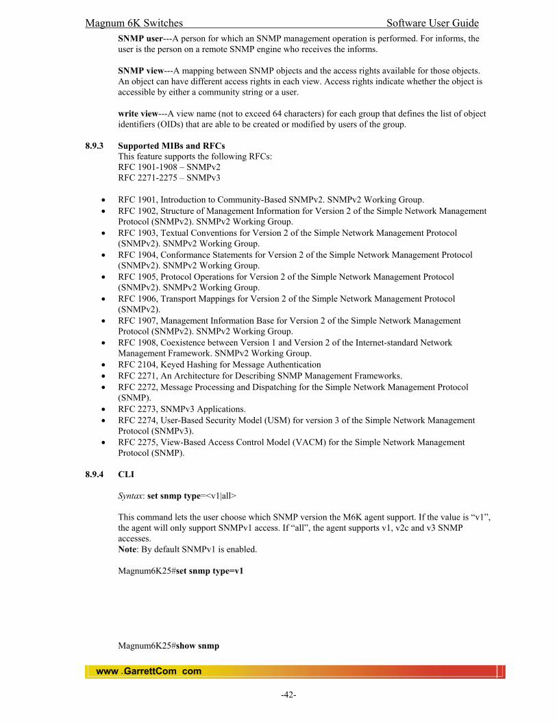
Magnum 6K Switches Software User Guide
www GarrettCom com..
-42-
SNMP user---A person for which an SNMP management operation is performed. For informs, the user is the person on a remote SNMP engine who receives the informs. SNMP view---A mapping between SNMP objects and the access rights available for those objects. An object can have different access rights in each view. Access rights indicate whether the object is accessible by either a community string or a user. write view---A view name (not to exceed 64 characters) for each group that defines the list of object identifiers (OIDs) that are able to be created or modified by users of the group.
8.9.3 Supported MIBs and RFCs This feature supports the following RFCs: RFC 1901-1908 – SNMPv2 RFC 2271-2275 – SNMPv3
• RFC 1901, Introduction to Community-Based SNMPv2. SNMPv2 Working Group. • RFC 1902, Structure of Management Information for Version 2 of the Simple Network Management
Protocol (SNMPv2). SNMPv2 Working Group. • RFC 1903, Textual Conventions for Version 2 of the Simple Network Management Protocol
(SNMPv2). SNMPv2 Working Group. • RFC 1904, Conformance Statements for Version 2 of the Simple Network Management Protocol
(SNMPv2). SNMPv2 Working Group. • RFC 1905, Protocol Operations for Version 2 of the Simple Network Management Protocol
(SNMPv2). SNMPv2 Working Group. • RFC 1906, Transport Mappings for Version 2 of the Simple Network Management Protocol
(SNMPv2). • RFC 1907, Management Information Base for Version 2 of the Simple Network Management
Protocol (SNMPv2). SNMPv2 Working Group. • RFC 1908, Coexistence between Version 1 and Version 2 of the Internet-standard Network
Management Framework. SNMPv2 Working Group. • RFC 2104, Keyed Hashing for Message Authentication • RFC 2271, An Architecture for Describing SNMP Management Frameworks. • RFC 2272, Message Processing and Dispatching for the Simple Network Management Protocol
(SNMP). • RFC 2273, SNMPv3 Applications. • RFC 2274, User-Based Security Model (USM) for version 3 of the Simple Network Management
Protocol (SNMPv3). • RFC 2275, View-Based Access Control Model (VACM) for the Simple Network Management
Protocol (SNMP).
8.9.4 CLI Syntax: set snmp type=<v1|all> This command lets the user choose which SNMP version the M6K agent support. If the value is “v1”, the agent will only support SNMPv1 access. If “all”, the agent supports v1, v2c and v3 SNMP accesses. Note: By default SNMPv1 is enabled. Magnum6K25#set snmp type=v1
Magnum6K25#show snmp
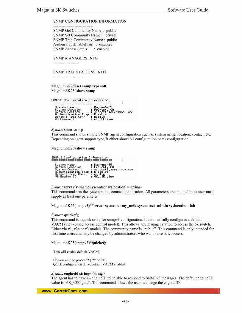
Magnum 6K Switches Software User Guide
www GarrettCom com..
-43-
SNMP CONFIGURATION INFORMATION ------------------------------ SNMP Get Community Name : public SNMP Set Community Name : private SNMP Trap Community Name : public AuthenTrapsEnableFlag : disabled SNMP Access Status : enabled SNMP MANAGERS INFO ------------------ SNMP TRAP STATIONS INFO ----------------------- Magnum6K25#set snmp type=all Magnum6K25#show snmp
Syntax: show snmp This command shows simple SNMP agent configuration such as system name, location, contact, etc. Depending on agent support type, it either shows v1 configuration or v3 configuration. Magnum6K25#show snmp
Syntax: setvar[sysname|syscontact|syslocation]=<string> This command sets the system name, contact and location. All parameters are optional but a user must supply at least one parameter. Magnum6K25(snmpv3)##setvar sysname=my_m6k syscontact=admin syslocation=lab Syntax: quickcfg This command is a quick setup for snmpv3 configuration. It automatically configures a default VACM (view-based access control model). This allows any manager station to access the 6k switch. Either via v1, v2c or v3 models. The community name is “public”. This command is only intended for first time users and may be changed by administrators who want more strict access. Magnum6K25(snmpv3)#quickcfg This will enable default VACM. Do you wish to proceed? [ 'Y' or 'N' ] Quick configuration done, default VACM enabled Syntax: engineid string=<string> The agent has to have an engineID to be able to respond to SNMPv3 messages. The default engine ID value is “6K_v3Engine”. This command allows the user to change the engine ID.

Magnum 6K Switches Software User Guide
www GarrettCom com..
-44-
Magnum6K25(snmpv3)##engineid string=6k Engine ID is set successfully Syntax: authtrap <enable|disable> This command enables or disables authentication traps generation. Magnum6K25(snmpv3)##authtrap enable Authentication trap status is set successfully Syntax: show-authtrap This shows the current value of authentication trap status. Magnum6K25(snmpv3)##show-authtrap
Authentication Trap Status: Disabled Syntax: deftrap community=<string> This command defines the default community string to be used when sending traps. When user does not specify the trap community name when setting a trap station using the “trap” command, the default trap community name is used. Magnum6K25(snmpv3)##deftrap community=mysecret Default trap community is set successfully Syntax: show-deftrap This shows the current value of default trap. Magnum6K25(snmpv3)##show-deftrap Default Trap Community : public Syntax: trap <add|delete> id=<id> [type=<v1|v2|inform>] [host=<host-ip>] [community=<string>] [port=<1-65534>] This command is used to define the trap and inform manager stations. The station can receive v1, v2 traps and/or inform notifications. An inform notification is an acknowledgments that a trap has been received. A user can add up to 5 stations. Magnum6K25(snmpv3)##trap add id=1 type=v1 host=10.21.1.100 Entry is added successfully Syntax: show-trap [id=<id>] This commands shows the configured trap stations in tabular format. id – [optional] the trap entry number in the table. Magnum6K25(snmpv3)##show-trap
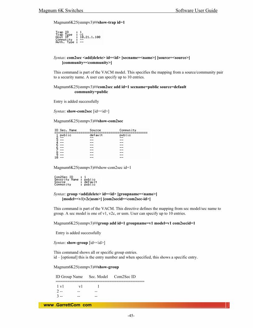
Magnum 6K Switches Software User Guide
www GarrettCom com..
-45-
Magnum6K25(snmpv3)##show-trap id=1
Syntax: com2sec <add|delete> id=<id> [secname=<name>] [source=<source>] [community=<community>] This command is part of the VACM model. This specifies the mapping from a source/community pair to a security name. A user can specify up to 10 entries. Magnum6K25(snmpv3)##com2sec add id=1 secname=public source=default community=public Entry is added successfully Syntax: show-com2sec [id=<id>] Magnum6K25(snmpv3)##show-com2sec
Magnum6K25(snmpv3)##show-com2sec id=1
Syntax: group <add|delete> id=<id> [groupname=<name>] [model=<v1|v2c|usm>] [com2secid=<com2sec-id>] This command is part of the VACM. This directive defines the mapping from sec model/sec name to group. A sec model is one of v1, v2c, or usm. User can specify up to 10 entries. Magnum6K25(snmpv3)##group add id=1 groupname=v1 model=v1 com2secid=1 Entry is added successfully Syntax: show-group [id=<id>] This command shows all or specific group entries. id – [optional] this is the entry number and when specified, this shows a specific entry. Magnum6K25(snmpv3)##show-group ID Group Name Sec. Model Com2Sec ID ====================================== 1 v1 v1 1 2 -- -- -- 3 -- -- --

Magnum 6K Switches Software User Guide
www GarrettCom com..
-46-
4 -- -- -- 5 -- -- -- 6 -- -- -- 7 -- -- -- 8 -- -- -- 9 -- -- -- 10 -- -- --
Magnum6K25(snmpv3)##show-group id=1 Group ID : 1 Group Name : v1 Model : v1 Com2Sec ID : 1 Syntax: view <add|delete> id=<id> [viewname=<name>] [type=<included|excluded>] [subtree=<oid>] [mask=<hex-string>] This is part of the VACM commands. A view defines a manager or group or manager stations what it can access inside the MIB object tree. A user can define up to 10 entries. Magnum6K25(snmpv3)##view add id=1 viewname=all type=included subtree=.1 Entry is added successfully Syntax: show-view [id=<id>] This command shows all or specific view entries. Magnum6K25(snmpv3)##show-view ID View Name Type Subtree Mask ============================================= 1 all included .1 ff 2 -- -- -- -- 3 -- -- -- -- 4 -- -- -- -- 5 -- -- -- -- 6 -- -- -- -- 7 -- -- -- -- 8 -- -- -- -- 9 -- -- -- -- 10 -- -- -- -- Magnum6K25(snmpv3)##show-view id=1 View ID : 1 View Name : all Type : included Subtree : .1 Mask : ff Syntax: access <add|delete> id=<id> [accessname=<name>] [model=<v1|v2c|usm|any>] [level=<noauth|auth|priv>] [read=<none|view-id>] [write=<none|view-id>] [notify=<none|view-id>] [context=<none|context-string>] [prefix=<exact|prefix>] This is also a part of VACM commands, the access command maps from group/security model/security level to a view. A user can add up to 10 access entries.
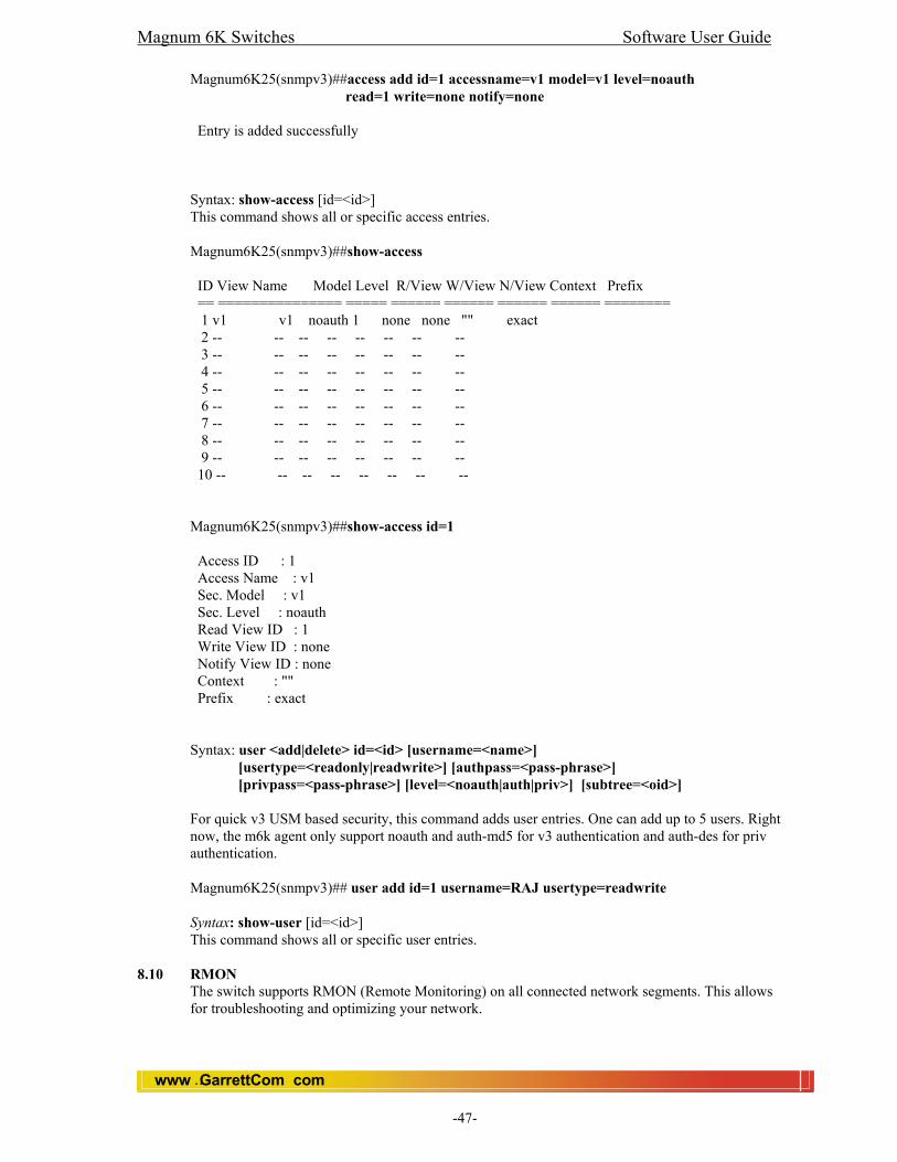
Magnum 6K Switches Software User Guide
www GarrettCom com..
-47-
Magnum6K25(snmpv3)##access add id=1 accessname=v1 model=v1 level=noauth read=1 write=none notify=none Entry is added successfully Syntax: show-access [id=<id>] This command shows all or specific access entries. Magnum6K25(snmpv3)##show-access ID View Name Model Level R/View W/View N/View Context Prefix == =============== ===== ====== ====== ====== ====== ======== 1 v1 v1 noauth 1 none none "" exact 2 -- -- -- -- -- -- -- -- 3 -- -- -- -- -- -- -- -- 4 -- -- -- -- -- -- -- -- 5 -- -- -- -- -- -- -- -- 6 -- -- -- -- -- -- -- -- 7 -- -- -- -- -- -- -- -- 8 -- -- -- -- -- -- -- -- 9 -- -- -- -- -- -- -- -- 10 -- -- -- -- -- -- -- -- Magnum6K25(snmpv3)##show-access id=1 Access ID : 1 Access Name : v1 Sec. Model : v1 Sec. Level : noauth Read View ID : 1 Write View ID : none Notify View ID : none Context : "" Prefix : exact Syntax: user <add|delete> id=<id> [username=<name>] [usertype=<readonly|readwrite>] [authpass=<pass-phrase>] [privpass=<pass-phrase>] [level=<noauth|auth|priv>] [subtree=<oid>] For quick v3 USM based security, this command adds user entries. One can add up to 5 users. Right now, the m6k agent only support noauth and auth-md5 for v3 authentication and auth-des for priv authentication. Magnum6K25(snmpv3)## user add id=1 username=RAJ usertype=readwrite Syntax: show-user [id=<id>] This command shows all or specific user entries.
8.10 RMON The switch supports RMON (Remote Monitoring) on all connected network segments. This allows for troubleshooting and optimizing your network.

Magnum 6K Switches Software User Guide
www GarrettCom com..
-48-
The Magnum 6K switches provides hardware-based RMON counters in the switch chipset. The switch manager CPU polls these counters periodically to collect the statistics in a format that compiles with the RMON MIB definition. The following RMON groups are supported:
• Ethernet Statistics Group - maintains utilization and error statistics for the switch port being monitored.
• History Group – gathers and stores periodic statistical samples from previous Statistics Group.
• Alarm Group – allows a network administrator to define alarm thresholds for any MIB variable.
• Log and Event Group – allows a network administrator to define actions based on alarms. SNMP Traps are generated when RMON Alarms are triggered.
The RMON agent automatically runs in the switch. Use the RMON management station on your network to enable or disable specific RMON traps and events.
8.10.1 Adding RMON Communities in the Switch The following RMON commands add new RMON communities: history def-owner = <string> statistics def-owner = <string> alarm def-owner = <string> event def-owner = <string> e.g., Magnum6K25(rmon)## event def-owner = “test” The show command lists the RMON data of specified type. Syntax: show rmon <stats|hist|event|alarm> Magnum6K25(snmp)##show rmon event
RMON Event Default Owner : monitor
RMON Event Default Community: public
8.11 Web: Viewing and Configuring SNMP Parameters
In the web browser interface: 1. Click on the [Administration] 2. Click on [SNMP].
You can modify community names, add SNMP manager station or add trap station from this menu.
Magnum 6K Switches Software User Guide
www GarrettCom com..
-49-
9.0 Monitoring and Analyzing Switch Operation 9.1 Overview
The Magnum 6K Switches have several built-in tools for monitoring, analyzing, and troubleshooting switch and network operations: Status: Includes options for displaying general Switch information, management address data, and MAC addresses. Event Log: Lists Switch operating events and Alert events. Configurable trap receivers: Uses SNMP to enable management stations on your network to receive the SNMP traps from the Switch. Port monitoring (mirroring): Copies all traffic from the specified ports to a designated monitoring port.
9.2 Port Monitoring (Mirroring) Features You can designate a port for monitoring traffic of one port (at a time) on the Switch. The Switch monitors the network activity by copying all traffic from the specified monitoring source (monitor port) to the designated monitoring (mirror or sniffer) port, to which a network analyzer can be attached.
9.2.1 CLI: Configuring Port Monitoring You must use the following configuration sequence to configure port monitoring in the CLI: 1. Assign a monitoring (mirroring) or sniffer port. 2. Designate the port to monitor. To list the ports assigned to mirror (receive monitored traffic) and the ports being monitored you need to use the command below: Syntax: show port-mirror For example, if you assign port 12 as the monitoring port and configure the Switch to monitor port 3, show port-mirror displays the following: Magnum 6K25# show port-mirror Port mirroring is Enabled Monitor Port is : 3 Sniffer Port is : 12 Configuring the monitor port assigns or removes a monitoring port. This must be executed from the configuration level. Removing the monitor port disables port monitoring and resets the monitoring parameters to their factory-default settings. Magnum 6K25# port-mirror <enter> Magnum6K25(port-mirror)## syntax: setport monitor=<monitor port number> sniffer=<sniffer port number> For example, to assign port 12 as the monitoring port and 3 as the monitored port, type Magnum6K25(port-mirror)## setport monitor=3 sniffer=12 Port 3 set as Monitor Port Port 12 set as Sniffer Port To turn on or off the port monitoring syntax: prtmr <enable|disable>
Magnum 6K Switches Software User Guide
www GarrettCom com..
-50-
Magnum6K25(port-mirror)## prtmr enable Port Mirroring Enabled Magnum6K25(port-mirror)## prtmr disable Port Mirroring Disabled Note: Port Mirroring cannot be enabled until or unless user assigns the monitor and sniffer ports.
9.3 Limitation
• One port can monitor at a time. • Source port and sniffer port must be the members of the same VLAN.
9.4 Web: Viewing Port Monitor status In the web browser interface: 1. Click on the [Configuration] 2. Click on [Port]. 3. Click on [Mirroring]. 4. Click on [Modify] button. 5. After you make the desired changes, click on [OK] button. 6. Click [Save] to save the configuration.
Magnum 6K Switches Software User Guide
www GarrettCom com..
-51-
10.0 Optimizing Port Usage 10.1 Overview
This chapter includes: • Configuring port, status, mode (speed and duplex), and flow control parameters. • Configuration screens corresponding to the port numbers on the front of the switch.
10.2 CLI: Viewing Port Status and Configuring Port Parameters
From the CLI commands, you can configure and view all port parameter settings and view all port status indicators.
10.2.1 Port Status and Configuration Features Status or Parameter Description ---------------------------------- -------------------- Status Enable (default): The port is ready for a network connection.
Disable: The port will not operate even when properly connected in a network. Use this setting if the port needs to be shut down for diagnostic purposes or while you are making topology changes.
Link Up: The port senses a linkbeat.
Down: The port is not enabled, has no cables connected, or is experiencing a network error. For troubleshooting information, see the installation manual you received with the switch. See also chapter 10, “ Troubleshooting” (in this manual).
Mode The port’s speed and duplex (data transfer operation) setting. 10/100Base-T ports: • Auto (default): Senses speed and negotiates with the port at the other end of the link for data transfer operation (half-duplex or full-duplex). Note: Ensure that the device attached to the port is configured for the same setting that you selected here. Also, if “ Auto” is used, the device to which the port is connected must operate in compliance with the IEEE 802.3u “Auto Negotiation” standard for 100Base-T networks. If the other device does not comply with the 802.3u standard, or is not set to “Auto”, then the port configuration on the switch must be manually set to match the port configuration on the other device. To see what the switch negotiated for the Auto setting, use the CLI show port command. Possible port setting combinations for copper ports.
10HDx: 10 Mbps, Half-Duplex 10FDx: 10 Mbps, Full-Duplex 100HDx: 100 Mbps, Half-Duplex 100FDx: 100 Mbps, Full-Duplex
Possible port settings for 100FX ports:
100FDx (default): 100 Mbps, Full-Duplex 100HDx: 100 Mbps, Half-Duplex
Possible port settings for 10FL ports:
10HDx (default): 10 Mbps, Half-Duplex 10FDx: 10 Mbps, Full-Duplex
100/1000Base-T ports: • Auto (default): Senses speed and negotiates with the port at the

Magnum 6K Switches Software User Guide
www GarrettCom com..
-52-
other end of the link for port operation (MDI-X or MDI). To see what the switch negotiated for the Auto setting, use the CLI show port command.
1000Fdx: 1000 Mbps (1Gbps), Full-Duplex only 100Fdx: 100 Mbps, Full-Duplex
Notes: • To change the port speed on a transceiver port you are required to reboot the switch. • Ensure that the device attached to the port is configured for the same setting that you selected here. Also, if “ Auto” is used, the device the port is connected to must also be configured to “ Auto” and operate in compliance with the IEEE 802.3ab “ Auto Negotiation” standard for 1000Base-T networks. Gigabit fiber-optic ports (Gigabit-SX and Gigabit-LX):
1000FDx (default): 1000 Mbps (1 GBPS), Full Duplex only
• Auto: The port operates at 1000FDx and auto-negotiates flow control with the device connected to the port.
Flow Control • Disabled (default): The port will not generate flow control packets and drops received flow control packets. • Enabled: The port uses 802.3x Link Layer Flow Control, generates flow control packets, and processes received flow control packets. With the port mode set to “Auto” (the default) and “Flow Control” set to enabled, the switch negotiates Flow Control on the indicated port. If the port mode is not set to “Auto”, or if “Flow Control” is disabled on the port, then Flow Control is not used.
Back Pressure • Disabled (default): The port will not have Back pressure-based
congestion control. • Enabled: The port uses 802.3 Layer 2 back off algorithms. Back
pressure-based congestion control on half-duplex, 10-Mbps Ethernet ports.
10.2.2 Port Status and Configuration Commands From the CLI, you can configure and view all port parameter settings and all port status indicators. Please see CLI section for details.
10.2.3 Using the CLI to View Port Status Use the following commands to display port status and configuration: show port: Lists the full status and configuration for all ports on the switch. Syntax: show port

Magnum 6K Switches Software User Guide
www GarrettCom com..
-53-
Syntax: show port=<Port number>: Lists the status of the specific port. Magnum6K25# show port=2
10.2.4 Using the CLI to Configure Ports
You can configure one or more of the following port parameters under device module. Magnum6K25#device <enter> Magnum6K25(device)## For details on each option, see Table above. Syntax: setport port=<port|list|range> [name=<name>] [speed=<10|100>] [duplex=<half|full>] [auto=<enable|disable>] [flow=<enable|disable>] [bp=<enable|disable>] [status=<enable|disable>] For example, to configure ports 1 through 4 and port 7 for 100Mbps full-duplex, you would enter this command: Note: The factory default setting for 10/100 copper ports is "Auto-negotiation Enabled". Before changing the port setting of a copper port, you have to ‘Disable’ the Auto- negotiation Magnum6K25(device)## setport port=1-4,7 speed=100 duplex=full Similarly, to configure a single port with the settings in the above command, you could enter the same command with only the one port identified. Magnum6K25(device)## setport port=7 speed=100 duplex=full If port 8 was disabled, and you wanted to enable it and configure it for 100FDx you could do so with the following command. Magnum6K25(device)## setport port=8 status=enable speed=100 duplex=full
Magnum 6K Switches Software User Guide
www GarrettCom com..
-54-
To set flowcontrol Syntax: flowcontrol xonlimit=<value> xofflimit=<value>
Where, xonlimit can be from 3 to 127, default value is 4 xofflimit from 3 to 127, default value is 6
Magnum6K25#show flowcontrol XOnLimit : 4 XOffLimit : 6 To set BackPressure Syntax: backpressure rxthreshold=<value>
Where, rxthreshold value can be from 3 to 127, default is 28
Magnum6K25#show backpressure Rx Buffer Threshold : 28
To set the Age Time
Syntax: setage time=<timeout-period> Note: Default value is 300 seconds.
Magnum6K25#show age Address table age time = 300
10.3 Web: Viewing Port Status and Configuring Port Parameters
In the web browser interface: 1. Click on the Configuration. 2. Click on [Port]. 3. Click on [Settings]. 4. Select a port to modify. 5. After you make the desired changes, click on [OK] button. 6. Click [Save] to save the configuration.
10.4 Broadcast Storm Protection
One of the best features of the Magnum 6K is its ability to keep broadcast storms from spreading throughout a network. Network storms are characterized by an excessive number of broadcast packets being sent over the network. These storms can occur if network equipment is configured incorrectly, network software is not properly functioning, or poorly designed programs (including some network games) are used. Storms can reduce network performance and cause bridges, routers, workstations, servers and PC's to slow down or even crash.
10.4.1 How does it works The Magnum 6K is capable of detecting and limiting storms on each interface (Port). A network administrator can set the maximum number of broadcast frames (Threshold value) that are permitted from a particular interface every second. If that maximum number is exceeded, a storm condition is declared. Once it is determined that a storm is occurring on an interface, any additional broadcast packets received on that interface will be dropped until the storm is determined to be over. The storm is determined to be over when a one-second period elapses with no broadcast packets received on that interface.
10.4.2 CLI: To Enable/Disable the broadcast Protection
Syntax: broadcast-protect <enable|disable> Magnum6K25(device)##broadcast-protect enable Broadcast Storm Protection enabled
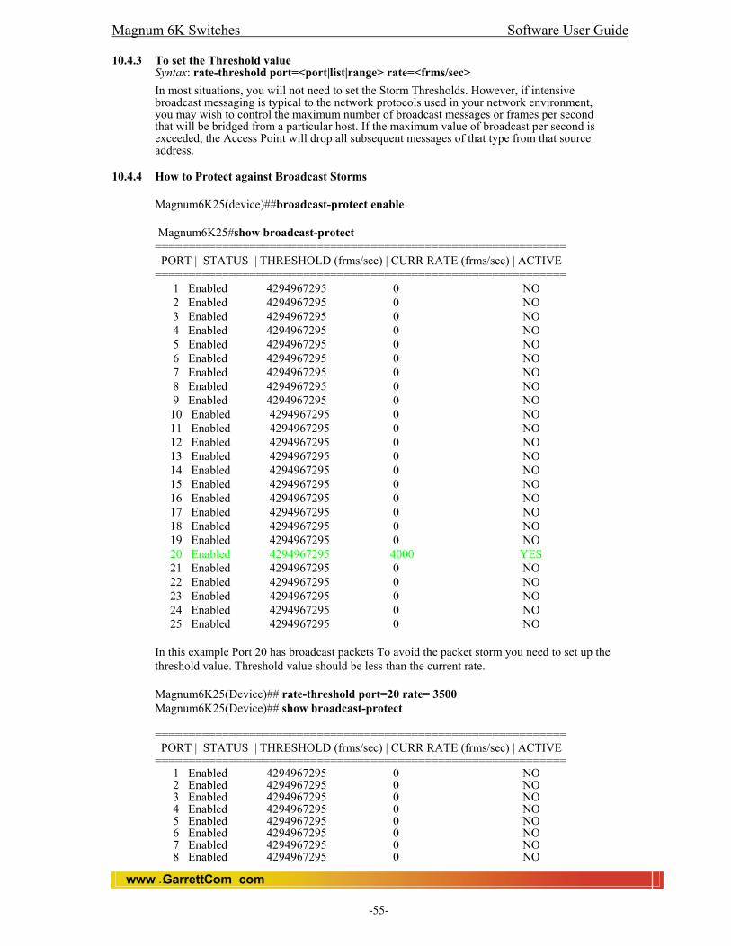
Magnum 6K Switches Software User Guide
www GarrettCom com..
-55-
10.4.3 To set the Threshold value
Syntax: rate-threshold port=<port|list|range> rate=<frms/sec> In most situations, you will not need to set the Storm Thresholds. However, if intensive broadcast messaging is typical to the network protocols used in your network environment, you may wish to control the maximum number of broadcast messages or frames per second that will be bridged from a particular host. If the maximum value of broadcast per second is exceeded, the Access Point will drop all subsequent messages of that type from that source address.
10.4.4 How to Protect against Broadcast Storms Magnum6K25(device)##broadcast-protect enable Magnum6K25#show broadcast-protect ============================================================= PORT | STATUS | THRESHOLD (frms/sec) | CURR RATE (frms/sec) | ACTIVE ============================================================= 1 Enabled 4294967295 0 NO 2 Enabled 4294967295 0 NO 3 Enabled 4294967295 0 NO 4 Enabled 4294967295 0 NO 5 Enabled 4294967295 0 NO 6 Enabled 4294967295 0 NO 7 Enabled 4294967295 0 NO 8 Enabled 4294967295 0 NO 9 Enabled 4294967295 0 NO 10 Enabled 4294967295 0 NO 11 Enabled 4294967295 0 NO 12 Enabled 4294967295 0 NO 13 Enabled 4294967295 0 NO 14 Enabled 4294967295 0 NO 15 Enabled 4294967295 0 NO 16 Enabled 4294967295 0 NO 17 Enabled 4294967295 0 NO 18 Enabled 4294967295 0 NO 19 Enabled 4294967295 0 NO 20 Enabled 4294967295 4000 YES 21 Enabled 4294967295 0 NO 22 Enabled 4294967295 0 NO 23 Enabled 4294967295 0 NO 24 Enabled 4294967295 0 NO
25 Enabled 4294967295 0 NO In this example Port 20 has broadcast packets To avoid the packet storm you need to set up the threshold value. Threshold value should be less than the current rate. Magnum6K25(Device)## rate-threshold port=20 rate= 3500 Magnum6K25(Device)## show broadcast-protect ============================================================= PORT | STATUS | THRESHOLD (frms/sec) | CURR RATE (frms/sec) | ACTIVE ============================================================= 1 Enabled 4294967295 0 NO 2 Enabled 4294967295 0 NO 3 Enabled 4294967295 0 NO 4 Enabled 4294967295 0 NO 5 Enabled 4294967295 0 NO 6 Enabled 4294967295 0 NO 7 Enabled 4294967295 0 NO 8 Enabled 4294967295 0 NO
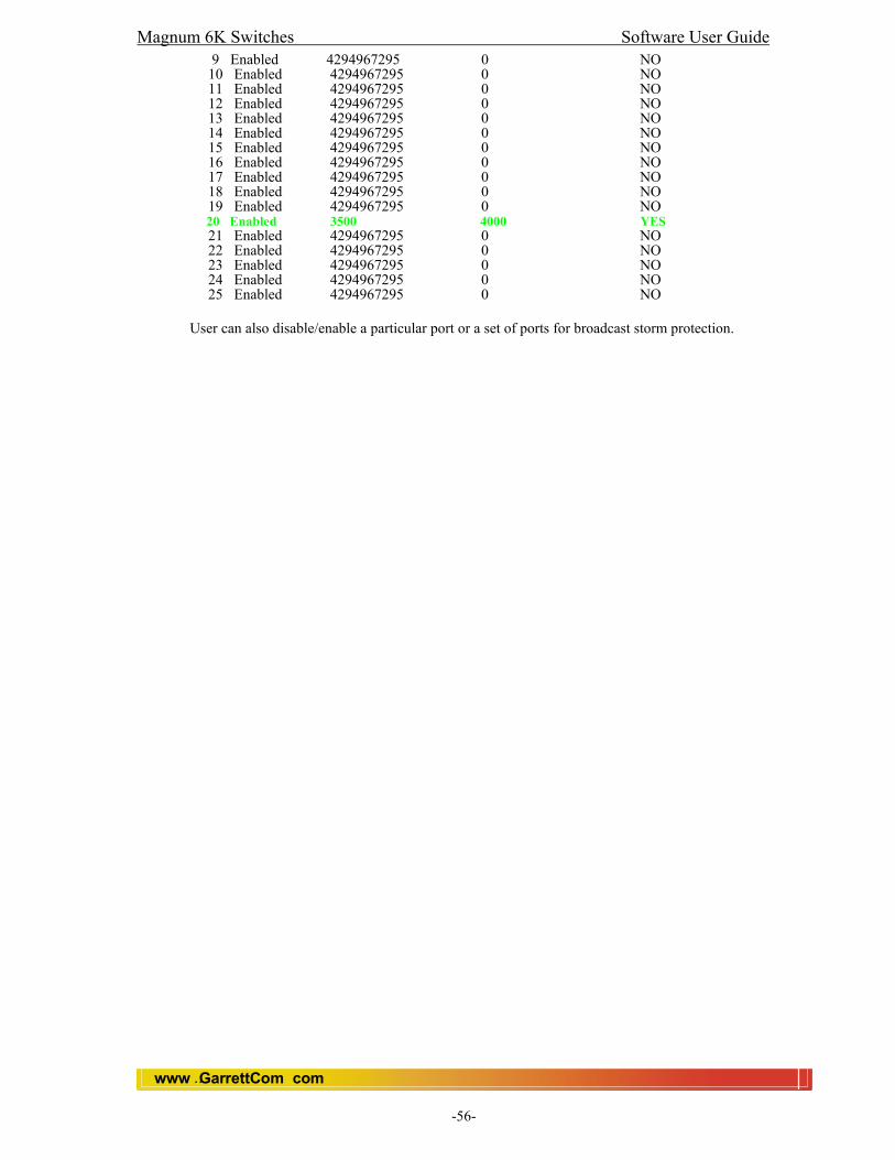
Magnum 6K Switches Software User Guide
www GarrettCom com..
-56-
9 Enabled 4294967295 0 NO 10 Enabled 4294967295 0 NO 11 Enabled 4294967295 0 NO 12 Enabled 4294967295 0 NO 13 Enabled 4294967295 0 NO 14 Enabled 4294967295 0 NO 15 Enabled 4294967295 0 NO 16 Enabled 4294967295 0 NO 17 Enabled 4294967295 0 NO 18 Enabled 4294967295 0 NO 19 Enabled 4294967295 0 NO 20 Enabled 3500 4000 YES 21 Enabled 4294967295 0 NO 22 Enabled 4294967295 0 NO 23 Enabled 4294967295 0 NO 24 Enabled 4294967295 0 NO 25 Enabled 4294967295 0 NO
User can also disable/enable a particular port or a set of ports for broadcast storm protection.
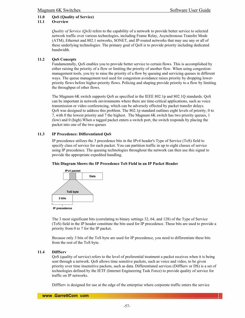
Magnum 6K Switches Software User Guide
www GarrettCom com..
-57-
11.0 QoS (Quality of Service) 11.1 Overview
Quality of Service (QoS) refers to the capability of a network to provide better service to selected network traffic over various technologies, including Frame Relay, Asynchronous Transfer Mode (ATM), Ethernet and 802.1 networks, SONET, and IP-routed networks that may use any or all of these underlying technologies. The primary goal of QoS is to provide priority including dedicated bandwidth.
11.2 QoS Concepts
Fundamentally, QoS enables you to provide better service to certain flows. This is accomplished by either raising the priority of a flow or limiting the priority of another flow. When using congestion-management tools, you try to raise the priority of a flow by queuing and servicing queues in different ways. The queue management tool used for congestion avoidance raises priority by dropping lower-priority flows before higher-priority flows. Policing and shaping provide priority to a flow by limiting the throughput of other flows. The Magnum 6K switch supports QoS as specified in the IEEE 802.1p and 802.1Q standards. QoS can be important in network environments where there are time-critical applications, such as voice transmission or video conferencing, which can be adversely effected by packet transfer delays. QoS was designed to address this problem. The 802.1p standard outlines eight levels of priority, 0 to 7, with 0 the lowest priority and 7 the highest. The Magnum 6K switch has two priority queues, 1 (low) and 0 (high).When a tagged packet enters a switch port, the switch responds by placing the packet into one of the two queues
11.3 IP Precedence: Differentiated QoS
IP precedence utilizes the 3 precedence bits in the IPv4 header's Type of Service (ToS) field to specify class of service for each packet. You can partition traffic in up to eight classes of service using IP precedence. The queuing technologies throughout the network can then use this signal to provide the appropriate expedited handling.
This Diagram Shows the IP Precedence ToS Field in an IP Packet Header
The 3 most significant bits (correlating to binary settings 32, 64, and 128) of the Type of Service (ToS) field in the IP header constitute the bits used for IP precedence. These bits are used to provide a priority from 0 to 7 for the IP packet. Because only 3 bits of the ToS byte are used for IP precedence, you need to differentiate these bits from the rest of the ToS byte.
11.4 DiffServ
QoS (quality of service) refers to the level of preferential treatment a packet receives when it is being sent through a network. QoS allows time sensitive packets, such as voice and video, to be given priority over time insensitive packets, such as data. Differentiated services (DiffServ or DS) is a set of technologies defined by the IETF (Internet Engineering Task Force) to provide quality of service for traffic on IP networks.
DiffServ is designed for use at the edge of the enterprise where corporate traffic enters the service
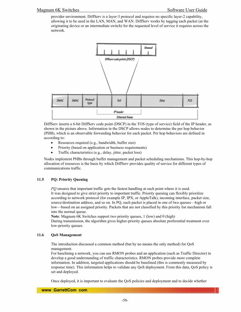
Magnum 6K Switches Software User Guide
www GarrettCom com..
-58-
provider environment. DiffServ is a layer-3 protocol and requires no specific layer-2 capability, allowing it to be used in the LAN, MAN, and WAN. DiffServ works by tagging each packet (at the originating device or an intermediate switch) for the requested level of service it requires across the network.
DiffServ inserts a 6-bit DiffServ code point (DSCP) in the TOS (type of service) field of the IP header, as shown in the picture above. Information in the DSCP allows nodes to determine the per hop behavior (PHB), which is an observable forwarding behavior for each packet. Per hop behaviors are defined in according to:
• Resources required (e.g., bandwidth, buffer size) • Priority (based on application or business requirements) • Traffic characteristics (e.g., delay, jitter, packet loss)
Nodes implement PHBs through buffer management and packet scheduling mechanisms. This hop-by-hop allocation of resources is the basis by which DiffServ provides quality of service for different types of communications traffic.
11.5 PQ: Priority Queuing
PQ ensures that important traffic gets the fastest handling at each point where it is used. It was designed to give strict priority to important traffic. Priority queuing can flexibly prioritize according to network protocol (for example IP, IPX, or AppleTalk), incoming interface, packet size, source/destination address, and so on. In PQ, each packet is placed in one of two queues—high or low—based on an assigned priority. Packets that are not classified by this priority list mechanism fall into the normal queue. Note: Magnum 6K Switches support two priority queues, 1 (low) and 0 (high) During transmission, the algorithm gives higher-priority queues absolute preferential treatment over low-priority queues.
11.6 QoS Management
The introduction discussed a common method (but by no means the only method) for QoS management. For baselining a network, you can use RMON probes and an application (such as Traffic Director) to develop a good understanding of traffic characteristics. RMON probes provide more complete information. In addition, targeted applications should be baselined (this is commonly measured by response time). This information helps to validate any QoS deployment. From this data, QoS policy is set and deployed.
Once deployed, it is important to evaluate the QoS policies and deployment and to decide whether

Magnum 6K Switches Software User Guide
www GarrettCom com..
-59-
additional services are needed. In addition, RMON probes should still continue to monitor the network because the traffic characteristics likely will change. A constant look at network traffic will help with changing trends and allow a network administrator to address new network requirements more expeditiously.
11.7 QoS on Ethernet
The Magnum 6K Switches have the capability to provide QoS at Layer 2. At Layer 2, the frame uses type of service (ToS) as specified in IEEE 802.1p . ToS uses 3 bits, just like IP precedence, and maps well from Layer 2 to layer 3, and vice versa. The switches have the capability to differentiate frames based on ToS settings. When two queues are present (high or low), frames can be placed in either and serviced via the weight set on all ports. This placement of queues, added to the weight set plus the particular tag setting on a packet allows each queue to have different service levels.
Magnum QoS implementations provided mapping of ToS (or IP precedence) to CoS (class of service). In this instance, an Ethernet frame CoS setting can be mapped to the ToS byte of the IP packet, and vice versa. A ToS level of 1 equals a CoS level of 1. This provides end-to-end priority for the traffic flow.
11.8 CLI
Magnum 6K Switches support three types of QoS; Port based, Tag based and ToS based (Layer 3). 11.8.1 To set the QoS type on the switch.
Magnum6K25#qos <enter> Magnum6K25(qos)##
Note: QoS is disabled by default on the switch. Set QoS <type> [ports] [priority] [tos] [tag] : Sets the QOS for a particular port. The following types of QOS are supported:
a. Port QOS b. Tag QOS c. Tos QOS (Layer 3) d. None.
Note: Not all packets received on a port have high priority. IGMP and BPDU packets have high priority by default.
11.8.2 Functions of QoS settings:
Port QOS: If we set a port to high priority then all the packets received on that port will be assigned to high priority regardless of the type of the packet. TAG QOS: If a packet contains a tag, the port (if tag QoS is enabled) on which the packet was received then looks to see at which level that tag value is set. Regardless of the tag value, if there is a tag, that packet is automatically assigned high priority. TOS QOS: (Layer 3) When a port is set to TOS QOS, the most significant 6-bits of the IPv4 packet (which has 64 bits) are used. If the 6 bits are set to TOS QOS for the specific port number the packet went to, that packet is assigned high priority by that port. Syntax: setqos type=<port|tag|tos|none> [port=<port|list|range>] [priority=<high|low>] [tos=<0-63|list|range>][tag=<0-7|list|range>]
Depending on the type of QOS, the corresponding field has to be set. For example, for QOS type tag, the tag levels have to be set, and for QOS type ToS, the ToS levels have to be set. If the priority field is not set, it then defaults to low priority. ToS has 64 levels and the valid values are 0-63 and a tagged

Magnum 6K Switches Software User Guide
www GarrettCom com..
-60-
packet has 8 levels and the valid values are 0-7.
Note: Setting type to none will clear the QOS (Disable) for all the ports.
Set port weight: Sets the port priority weight for All the ports. Once the weight is set, all the ports will be the same weight across the switch. The valid value for weight is 0-7. Syntax: set-weight weight=<0-7> Note A weight is a number calculated from the IP precedence setting for a packet in flow. This weight is used in an algorithm to determine when the packet will be serviced. Weight settings can be viewed using the show-portweight command. As mentioned previously, the switch is capable of detecting higher-priority packets marked with precedence by the IP forwarder and can schedule them faster, providing superior response time for this traffic. The IP Precedence field has values between 0 (the default) and 7. As the precedence value increases, the algorithm allocates more bandwidth to that traffic to make sure that it is served more quickly when congestion occurs. We can assign a weight to each flow, which determines the transmit order for queued packets. In this scheme, lower weights (set on all ports) are provided more service. IP precedence serves as a divisor to this weighting factor. For instance, traffic with an IP Precedence field value of 7 gets a lower weight than traffic with an IP Precedence field value of 3, and thus has priority in the transmit order. Syntax: set-weight weight=<0-7> One you set the Port weight, the hardware will interpret the weight setting for all ports as outlined below: Setting Hardware Interpretation 0 - 1 packet transmitted from HIGH, 1 packet from LOW 1 - 2 packet transmitted from HIGH, 1 packet from LOW 2 - 4 packet transmitted from HIGH, 1 packet from LOW 3 - 6 packet transmitted from HIGH, 1 packet from LOW 4 - 8 packet transmitted from HIGH, 1 packet from LOW 5 - 10 packet transmitted from HIGH, 1 packet from LOW 6 - 12 packet transmitted from HIGH, 1 packet from LOW 7 - All packets transmitted from HIGH, 0 packets from LOW. show portweight : Shows the global port priority weight. Syntax: show-portweight Note: Port weight can be assign only globally (the whole switch has the same setting) Magnum6K25(qos)##show-portweight Port priority Weight set to 1 High : 1 Low. Show qos : It shows the QoS information. Syntax: show qos [type=<port|tag|tos>] [port=<port|list|range>] For example, To set the QoS type as “Port” and set particular ports (1-5) with high priority. Magnum6K25(qos)##setqos type=port port=1-5 priority=high

Magnum 6K Switches Software User Guide
www GarrettCom com..
-61-
To see just the QoS status. Magnum6K25(qos)##show qos
To see the QoS type. Magnum6K25(qos)##show qos type=port
To set QoS type Tag, This command will set the bits making tag levels 0, 4 and 7 high priority. Magnum6K25(qos)##setqos type=tag port=6-10 tag=0,4,7 priority=high
To show the tag level (0-7) Magnum6K25(qos)##show qos type=tag
Note: The default setting for traffic class is the low priority queue. All tagged frames will be directed to either the low or high priority queue as specified.
Magnum 6K Switches Software User Guide
www GarrettCom com..
-62-
11.9 To tag untagged packets. When a packet is received untagged and has to be transmitted, with an addition of 802.1Q
tag on transmit, then 802.1p priority tag is assigned depending on the untag value set. Hence if you set untag port=1 tag=2 priority=low, untagged packets received on that port will be tagged with a priority low upon transmit. set-untag : The 802.1p user priority assigned to untagged received packets to be transmitted as tagged from the priority queue 1/0. Syntax: set-untag port=<port|list|range> priority=<high|low> tag=<0-7>
11.10 Web: Configure QoS
In the web browser interface: 1. Click on the [Configuration] 2. Click on [QoS]. 3. Click on [Modify]. 4. After you make the desired changes, click on [OK] button. 5. Click [Save] to save the configuration.

Magnum 6K Switches Software User Guide
www GarrettCom com..
-63-
12.0 IGMP 12.1 Overview
In a network where IP multicast traffic is transmitted for various multimedia applications, you can use the switch to reduce unnecessary bandwidth usage on a per-port basis by configuring IGMP (Internet Group Management Protocol controls). In the factory default state (IGMP disabled), the switch forwards all IGMP traffic to all ports, which can cause unnecessary bandwidth usage on ports not belonging to multicast groups. Enabling IGMP allows the ports to detect IGMP queries, report packets and manage IP multicast traffic through the switch.
12.2 Purpose
The purpose of IGMP Snooping is to limit multicast traffic to only those LAN segments that are interested in receiving the messages. In normal switch operations without IGMP, IP multicast traffic is flooded through out the whole LAN. It is flooded because a switch usually learns MAC address by looking in to the source address field of all the frames it receives. However, since a multicast address is never used as a source address for a packet (it has several false addresses which are not unique) and since they do not appear in the MAC address table (because they are not real), the switch has no method for learning them. The most efficient method to weed them out is to use IGMP Snooping. With IGMP Snooping the switch intercepts the IGMP messages (multicast messages only) from the host itself and updates its MAC table accordingly. IGMP is useful in multimedia applications such as LAN TV, desktop conferencing, and collaborative computing, where there is multipoint communication; that is, communication from one to many hosts, or communication originating from many hosts and destined for many other hosts. In such multipoint applications, IGMP will be configured on the hosts, and multicast traffic will be generated by one or more servers (inside or outside of the local network). Switches in the network (that support IGMP) can then be configured to direct the multicast traffic to only the ports where needed.
Enabling IGMP allows the ports to detect IGMP queries and report packets and manage IP multicast traffic through the switch. If no other querier is detected, the switch will then also function as the querier. (If you need to disable the querier feature, you can do so through the IGMP configuration MIB. Refer to “Changing the Querier Configuration Setting”)
12.3 IGMP Operating Features
In the factory default configuration, IGMP is disabled. IGMP works only on default VLAN (DEFAULT_VLAN; VID = 1). When you use either the CLI or the Telnet interface to enable IGMP on the switch, the switch forwards IGMP traffic only to ports belonging to multicast groups.
Auto/Blocked/Forward: You can use the console to configure individual ports to any of the following
states:
• Auto (the default): Causes the switch to interpret IGMP packets and to filter IP multicast traffic based on the IGMP packet information for ports belonging to a multicast group. This means that IGMP traffic will be forwarded on a specific port only if an IGMP host or multicast router is connected to the port.
• Blocked: Causes the switch to drop all IGMP transmissions received from a specific port and to block all outgoing IP Multicast packets for that port. This has the effect of preventing IGMP traffic from moving through specific ports.
• Forward: Causes the switch to forward all IGMP and IP multicast transmissions through the port.
Querier: In the default state (enabled), eliminates the need for a multicast router. In most cases,
GarrettCom recommends that you leave this parameter in the default “enabled” state even if you have a multicast router performing the querier function in your multicast group.
12.4 Benefit
The IGMP Snooping feature enables the switch to monitor the flow of queries from the router and reports from the host nodes to build its own multicast membership lists. It uses the lists to forward
Magnum 6K Switches Software User Guide
www GarrettCom com..
-64-
multicast packets only to switch ports where there are host nodes that are members of multicast groups. This improves switch performance and network security by further restricting the flow of multicast packets only to those switch ports connected to host nodes. Without IGMP Snooping, the switch would flood all multicast packets out all of its ports, except the port on which it received the packet. Such flooding of packets can negatively impact switch and network performance.
12.5 How IGMP Operates
The Internet Group Management Protocol (IGMP) is an internal protocol of the Internet Protocol (IP) suite. IP manages multicast traffic by using switches, multicast routers, and hosts that support IGMP. (In the Magnum 6K Switches implementation of IGMP, a multicast router is not necessary as long as a switch is configured to support IGMP with the querier feature enabled.) A set of hosts, routers, and/or switches that send or receive multicast data streams to or from the same source(s) is termed a multicast group, and all devices in the group use the same multicast group address. The multicast group running version 2 of IGMP uses three fundamental types of messages to communicate:
• Query: A message sent from the querier (multicast router or switch) asking for a response from
each host belonging to the multicast group. If a multicast router supporting IGMP is not present, then the switch must assume this function in order to elicit group membership information from the hosts on the network. (If you need to disable the querier feature, you can do so through the CLI, using the IGMP configuration MIB. See “Changing the Querier Configuration Setting” on page “Configuring the Querier Function”)
• Report: A message sent by a host to the querier to indicate that the host wants to be or is a member of a given group indicated in the report message.
• Leave Group: A message sent by a host to the querier to indicate that the host has ceased to be a member of a specific multicast group. Thus, IGMP identifies members of a multicast group (within a subnet) and allows IGMP-configured hosts (and routers) to join or leave multicast groups.
12.6 IGMP Data.
To display data showing active group addresses, reports, queries, querier access port, and active group address data (port, type, and access), see “CLI Section”.
12.7 Role of the Switch
When IGMP is enabled on the switch, it examines the IGMP packets it receives: To learn which of its ports are linked to IGMP hosts and multicast routers/
queriers belonging to any multicast group. To become a querier if a multicast router/querier is not discovered on the network.
Once the switch learns the port location of the hosts belonging to any particular multicast group, it can direct group traffic to only those ports, resulting in bandwidth savings on ports where group members do not reside. The following example illustrates this operation.
Figure (below) shows a network running IGMP.
PCs 1 and 4, switch 2, and all of the routers are members of an IP multicast group. (The routers operate as queriers.)
Switch 1 ignores IGMP traffic and does not distinguish between IP multicast group members and non-members. Thus, it is sending large amounts of unwanted multicast traffic out the ports to PCs 2 and 3.
Switch 2 is recognizing IGMP traffic and learns that PC 4 is in the IP multicast group receiving multicast data from the video server (PC X). Switch 2 then sends the multicast data only to the port for PC 4, thus avoiding unwanted multicast traffic on the ports for PCs 5 and 6.
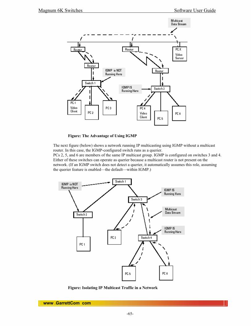
Magnum 6K Switches Software User Guide
www GarrettCom com..
-65-
Figure: The Advantage of Using IGMP
The next figure (below) shows a network running IP multicasting using IGMP without a multicast router. In this case, the IGMP-configured switch runs as a querier. PCs 2, 5, and 6 are members of the same IP multicast group. IGMP is configured on switches 3 and 4. Either of these switches can operate as querier because a multicast router is not present on the network. (If an IGMP switch does not detect a querier, it automatically assumes this role, assuming the querier feature is enabled—the default—within IGMP.)
Figure: Isolating IP Multicast Traffic in a Network
Magnum 6K Switches Software User Guide
www GarrettCom com..
-66-
In the above figure, the multicast group traffic does not go to switch 1 and beyond because either the port on switch 3 that connects to switch 1 has been configured as blocked or there are no hosts connected to switch 1 or switch 2 that belong to the multicast group.
For PC 1 to become a member of the same multicast group without flooding IP multicast traffic on all ports of switches 1 and 2, IGMP must be configured on both switches 1 and 2, and the port on Switch 3 that connects to Switch 1 must be unblocked.
12.8 IP Multicast Filters
IP multicast addresses occur in the range from 224.0.0.0 through 239.255.255.255 (which corresponds to the Ethernet multicast address range of 01005e-000000 through 01005e-7fffff). Devices such as the Magnum Switch 6K having static Traffic/Security filters configured with a “Multicast” filter type and a “Multicast Address” in this range will continue in effect unless IGMP learns of a multicast group destination in this range. In that case, IGMP takes over the filtering function for the multicast destination address(es) for as long as the IGMP group is active. If the IGMP group subsequently deactivates, the static filter resumes control over traffic to the multicast address formerly controlled by IGMP.
12.9 Reserved Addresses Excluded from IP Multicast (IGMP) Filtering.
Traffic to IP multicast groups in the IP address range of 224.0.0.0 to 224.0.0.255 will always be flooded because addresses in this range are “well known” or “reserved” addresses. Thus, if IP Multicast is enabled and there is an IP multicast group within the reserved address range, traffic to that group will be flooded instead of filtered by the switch.
12.10 IGMP Support
Magnum 6K support IGMP version 1 and version 2. The switch can act either as a querier or a nonquerier. The querier router periodically sends general query messages to solicit group membership information. Hosts on the network that are members of a multicast group send report messages. When a host leaves a group, it sends a leave group message. The difference between Version 1 and Version 2 is that version 1 does not have a “Leave” mechanism for the host.
Magnum 6K does pruning when there is a leave message or a time expires on a port, we prune the multicast group membership on that port.
Note: The Magnum 6K supports only the default VLAN. It can be enabled within a port VLAN, tagged VLAN, or no VLAN. It can snoop up to 256 Multicast Groups.
12.11 CLI 12.11.1 Enable/disable IGMP
Syntax: igmp <enable/disable> Note: By default IGMP is disable. To enable and disable IGMP in the switch, first go to IGMP context using the command “igmp” or “configure igmp”. Magnum6K25##igmp Magnum6K25(igmp)## Magnum6K25(igmp)##igmp disable IGMP is disabled Magnum6K25(igmp)##igmp enable IGMP is enabled

Magnum 6K Switches Software User Guide
www GarrettCom com..
-67-
12.11.2 Showing IGMP Configuration To show current IGMP operation, use the command “show igmp” available globally in the command line. For example: Magnum6K25#show igmp
IGMP State shows if IGMP is turned on (Enable) or off (Disable). Immediate Leave provides a mechanism for a particular host that wants to leave a multicast group. It disables the port (where the leave message is received) ability to transmit multicast traffic. Querier shows where the switch is acting a querier or a non-querier. Querier interval shows the time period in seconds on which the switch sends general host-query messages. Querier response interval specifies maximum amount of time in seconds that can elapse between when the querier sends a host-query message and when it receives a response from a host.
12.11.3 Showing Snooped Multicast Groups
Using the command “show-group” in IGMP command context will show the multicast groups being snooped. For example: Magnum6K25(igmp)##show-group
The GroupIp column shows the multicast groups. PortNo shows the port where the multicast group is being detected. Timer shows the amount of time left in seconds before the group port will be deleted (will not be able to route multicast traffic) if the switch does not receive a membership report. Leave pending column shows the number of leave messages received from this port.
12.11.4 Showing Detected Router Ports
To view detected IGMP-enabled router ports, use the command “show-router” in the IGMP command context. For example: Magnum6K25(igmp)##show-router RouterIp PortNo Timer -------------------------------------- 10.21.1.250 9 25
12.11.5 Enable/Disable Immediate Leave Processing
To enable or disable the switch to immediately process a host sending a leave message rather that wait for the timer to expire, use the command “set-leave” in the IGMP command context.
Magnum 6K Switches Software User Guide
www GarrettCom com..
-68-
Syntax: set-leave <enable|disable> Magnum6K25(igmp)##set-leave enable IGMP immediate leave status is enabled Magnum6K25(igmp)##show igmp IGMP State : Enabled ImmediateLeave : Enabled Querier : Enabled Querier Interval : 125 Querier Response Interval : 10 Magnum6K25(igmp)##set-leave disable IGMP immediate leave status is disabled Magnum6K25(igmp)##show igmp IGMP State : Enabled ImmediateLeave : Disabled Querier : Enabled Querier Interval : 125 Querier Response Interval : 10
12.11.6 Enable/Disable Switch as Querier
To enable or disable a switch as IGMP querier, use the command “set-querier” in the IGMP command context.
Syntax: set-querier <enable|disable> Magnum6K25(igmp)##set-querier enable IGMP querier status is enabled Magnum6K25(igmp)##show igmp IGMP State : Enabled ImmediateLeave : Disabled Querier : Enabled Querier Interval : 125 Querier Response Interval : 10 Magnum6K25(igmp)##set-querier disable IGMP querier status is disabled Magnum6K25(igmp)##show igmp IGMP State : Enabled ImmediateLeave : Disabled Querier : Disabled Querier Interval : 125 Querier Response Interval : 10
12.12 Setting the Host Membership Query Interval
The IGMP querier router periodically sends general host-query messages. These messages

Magnum 6K Switches Software User Guide
www GarrettCom com..
-69-
are sent to ask for group membership information. This is sent to the all-system multicast group address, 224.0.0.1. Note: The default value is 125 seconds. The valid range can be from 60 to 127 seconds. To set the value, use the command “set-qi” in the IGMP command context. Syntax: set-qi interval=<value> Magnum6K25(igmp)##set-qi interval=127 Query interval successfully set Magnum6K25(igmp)##show igmp IGMP State : Enabled ImmediateLeave : Disabled Querier : Disabled Querier Interval : 127 Querier Response Interval : 10
12.13 Setting the Query Response Interval
The query response interval is the maximum amount of time that can elapse between when the querier router sends a host-query message and when it receives a response from a host. Note: The Default value is 10 seconds. The Range can be from 2 to 270 seconds. Restrictions apply to the maximum value because of an internal calculation that is dependent on the value of the Query Interval. Syntax: set-qri interval=<value> Magnum6K25(igmp)##set-qri interval=11 Query response interval successfully set Magnum6K25(igmp)##show igmp IGMP State : Enabled ImmediateLeave : Disabled Querier : Disabled Querier Interval : 125 Querier Response Interval : 11 Every port can be individually set to three different IGMP modes (please see section “Showing IGMP Port Mode”). To set port mode, you use the command “set-port” in the IGMP command context. User can use the console to configure individual ports to any of the following states: Auto/Blocked/Forward (As described above in IGMP Operating Features).
• Auto – lets IGMP control whether the port should or should not participate sending multicast traffic
• Block – manually configures the port to always block multicast traffic • Forward – manually configures the port to always forward multicast traffic
12.14 Configure IGMP Port Mode
Syntax: set-port port=< port|list|range>> mode=<auto|forward|block> Magnum6K25(igmp)##set-port port=1-2 mode=forward Port mode is set.
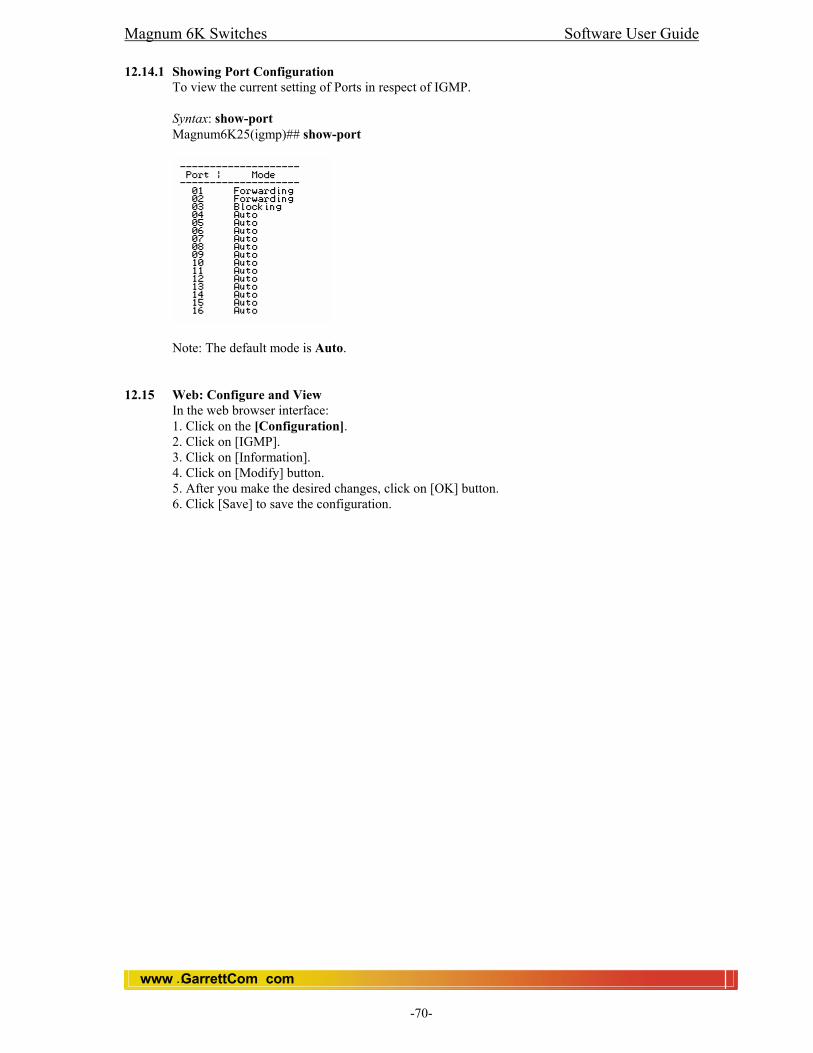
Magnum 6K Switches Software User Guide
www GarrettCom com..
-70-
12.14.1 Showing Port Configuration
To view the current setting of Ports in respect of IGMP. Syntax: show-port Magnum6K25(igmp)## show-port
Note: The default mode is Auto. 12.15 Web: Configure and View
In the web browser interface: 1. Click on the [Configuration]. 2. Click on [IGMP]. 3. Click on [Information]. 4. Click on [Modify] button. 5. After you make the desired changes, click on [OK] button. 6. Click [Save] to save the configuration.

Magnum 6K Switches Software User Guide
www GarrettCom com..
-71-
13.0 Spanning Tree Protocol (STP) 13.1 STP Features
The switch uses the IEEE 802.1D Spanning Tree Protocol (STP). When this STP is enabled, it ensures that only one path at a time is active between any two nodes on the network. In networks where more than one physical path exists between two nodes, STP ensures only a single path is active by blocking all redundant paths. Enabling STP is necessary in such networks because having more than one path between a pair of nodes causes loops in the network which can result in duplication of messages. This duplication leads to a “ broad-cast storm” that can bring down the network. Note: You should enable STP in any switch that is part of a redundant physical link (loop topology). (It is recommended that you enable STP on all switches belonging to a loop topology.) As recommended in the IEEE 802.1Q VLAN standard, the Magnum Switches use single-instance STP. This means a single spanning tree is created to make sure there are no network loops associated with any of the connections to the switch. This works regardless of whether VLANs are configured on the switch. Thus, these switches do not distinguish between VLANs when identifying redundant physical links.
13.2 Feature Default enable/disable STP disabled reconfiguring general operation priority: 32768 max age: 20 s hello time: 2 s fwd. delay: 15 s reconfiguring per-port STP path cost: var priority: 128 mode: norm monitoring STP n/a In the factory default configuration, STP is off. If a redundant link (loop) exists between nodes in your network, you should enable Spanning Tree. Note STP retains its current parameter settings when disabled. Thus, if you disable STP, then later re-enable it, the parameter settings will be the same as before STP was disabled. Caution Because the switch automatically gives faster links a higher priority, the default STP parameter settings are usually adequate for spanning tree operation. Also because incorrect STP settings can adversely affect network performance, you should not make changes unless you have a strong understanding of how STP operates. For more on STP, see the IEEE 802.1D standard.
13.3 Viewing the Current STP Configuration. Regardless of whether STP is disabled (the default), this command lists the switch’s full STP configuration, including general settings and port settings. Syntax: show stp <config | port | age> Magnum6K25# show stp config STP Bridge Configuration:
In the default configuration, STP appears as shown here:
Spanning Tree Enabled(Global) :NO Spanning Tree Enabled(Ports) :YES, 9,10,11,12,13,14,15,16,17,18,19,20,21,22 Bridge Priority :32768 Bridge Forward Delay :15 Bridge Hello Time :2 Bridge Max Age :20 Root Port :0 Root Path Cost :0 Designated Root :80:00:00:20:06:25:00:11 Designated Root Priority :32768 Root Bridge Forward Delay :15 Root Bridge Hello Time :2 Root Bridge Max Age :20

Magnum 6K Switches Software User Guide
www GarrettCom com..
-72-
13.3.1 Explaining Parameters in Detail The following parameters are explained in detail. Spanning Tree Enabled(Global): This field indicates whether STP is enabled or disabled globally i.e. if the values is YES, all ports have STP enabled, otherwise, all ports have STP disabled. Spanning Tree Enabled(Ports): This field indicates which ports have STP enabled. Bridge Priority: This field specifies the switch (bridge) priority value which is used along with the switch MAC address to determine the root device. Lower values mean higher priority. Value ranges from 0 to 65535. Default value is 32768. Bridge Forward Delay: This field indicates the time duration the switch will wait from listening to learning states and from learning to forwarding states. The value ranges from 4 to 30 seconds. Default value is 15. Bridge Hello Time: When the switch is the root device, this is the time between messages being transmitted. The value is from 1 to 10 seconds. Default value is 2 seconds. Bridge Max Age: This is the maximum age a received message with STP information is allowed by the switch before the switch checks all messages and updates the address table again. Value ranges from 6 to 40 seconds with default value of 20 seconds. Root Port: This field indicates the port number, which is elected as the root port of the switch. Root Path Cost: This field indicates the root ports path cost. A path cost is assigned to individual ports for the switch to determine which ports are the forwarding points. A higher cost means more loops, a lower cost means fewer loops. More loops equal more traffic and a slower system. Designated Root: This field shows the MAC address of the bridge in the network elected or designated as the root bridge. Designated Root Priority: This field shows the designated root bridge’s priority. Root Bridge Forward Delay: This field indicates the designated root bridge’s forward delay. This is the time the switch waits from the listening to the forwarding state. The default is 15 seconds. Can be set between 4-30 seconds. Root Bridge Hello Time: This field indicates the designated root bridge’s hello time. Root Bridge Max Age: This field indicates the designated root bridge’s Max Age.
13.3.2 Showing STP Configuration by Port
To show STP configuration by ports, an example shows below Magnum6K25#show stp ports STP Port Configuration: ------------------------------------------------------------------------------------------ Port# Type Priority Path Cost State Des. Bridge Des. Port ------------------------------------------------------------------------------------------ 01 TP(10/100) 128 100 Forwarding 80:00:00:20:06:25:00:62 80:01 02 TP(10/100) 128 100 Disabled 80:00:00:20:06:25:00:62 80:02 03 TP(10/100) 128 100 Disabled 80:00:00:20:06:25:00:62 80:03 04 TP(10/100) 128 100 Disabled 80:00:00:20:06:25:00:62 80:04 05 TP(10/100) 128 100 Forwarding 80:00:00:20:06:25:00:62 80:05 06 TP(10/100) 128 100 Disabled 80:00:00:20:06:25:00:62 80:06 07 TP(10/100) 128 100 Forwarding 80:00:00:20:06:25:00:62 80:07 08 TP(10/100) 128 100 Disabled 80:00:00:20:06:25:00:62 80:08
Magnum 6K Switches Software User Guide
www GarrettCom com..
-73-
The command above outputs the result in tabular format. The explanation of each column in the table is shown below: Port#: This field indicates the port number. Value ranges from 01 to max number of ports in the switch. Type: This field indicates the type of port. Priority: STP uses this to determine which ports are used for forwarding. Lower the number means higher priority. Value ranges from 0 to 255. Default is 128. Path Cost: This is the assigned port cost value used for the switch to determine the forwarding points. Values range from 1 to 65535. State: This indicates the STP state of individual ports. Values can be Listening, Learning, Forwarding, Blocking and Disabled. Des. Bridge: This is the port’s designated root bridge. Des. Port: This is the port’s designated root port.
13.4 Enabling or Disabling STP. Enabling STP implements the spanning-tree protocol for all physical ports on the switch, regardless of whether multiple VLANs are configured. Disabling STP removes protection against redundant loops that can significantly slow or halt a network. Go to STP configuration mode to configure STP. Syntax: stp <enter> Magnum6K25#stp <enter> Magnum6K25(stp)## To enable/disable STP Syntax: stp <enable|disable> Default: Disabled This command enables STP with the current parameter settings or disables STP without losing the most recently configured parameter settings. (To learn how the switch handles parameter changes, how to test changes without losing the previous settings, and how to replace previous settings with new settings, see appendix C, “ Switch Memory and Configuration”.) When enabling STP, you can also include the STP general and per-port parameters described in the next two sections. When you use the “no” form of the command, you can do so only to disable STP. (STP parameter settings are not changed when you disable STP, and cannot be included with the no spanning-tree command. Caution: Because incorrect STP settings can adversely affect network performance, GarrettCom recommends that you use the default STP parameter settings. You should not change these settings unless you have a strong understanding of how STP operates. For more on STP, see the IEEE 802.1D standard. Magnum6K25(stp)## stp enable
13.5 Reconfiguring General STP Operation on the Switch. This command enables STP (if it is not already enabled) and configures one or more of the following parameters:

Magnum 6K Switches Software User Guide
www GarrettCom com..
-74-
General STP Operating Parameters Name Default Range Function priority 32768 0 - 65535 Specifies the priority value used along with the switch MAC address to determine which device is root. The lower a
priority value, the higher the priority. maximum-age 20 seconds 6 – 40 sec Maximum received message age the switch allows for STP info before discarding messages and receiving new messages. Name Default Range Function hello-time 2 seconds 1 - 10 sec Time between message transmission when switch is the root. forward-delay 15 seconds 4 – 30 sec Time the switch waits before
transitioning from the listening to the learning state, and
between the learning state to the forwarding state. Syntax to set the above-mentioned parameters: priority port=<number|list|range> value=<0-255 / 0-65535> cost port=<number|list|range> value=<0-65535> time forward-delay=<4-30> hello=<1-10> age=<6-40> Default: See table above. For example, to enable STP with a maximum-age of 30 seconds and a hello-time of 3 seconds with forward delay of 15 secs: Magnum6K25(stp)## time forward-delay=15 hello= 3 age= 30
13.6 Globally Enabling or Disabling STP
To globally enable or disable STP on the switch, one must be in the STP context in CLI. The following command sequence shows enabling and disabling STP globally. Magnum6K25(stp)##show stp config STP Configuration: Spanning Tree Enabled(Global) :NO Spanning Tree Enabled(Ports) :YES, 1,2,3,4,5,6,7,8 Bridge Priority :32768 Bridge Forward Delay :15 Bridge Hello Time :2 Bridge Max Age :20 Root Port :1 Root Path Cost :100 Designated Root :80:00:00:01:96:ed:a7:80 Designated Root Priority :32768 Root Bridge Forward Delay :15 Root Bridge Hello Time :2 Root Bridge Max Age :20 Magnum6K25(stp)##stp enable Successfully set the STP status
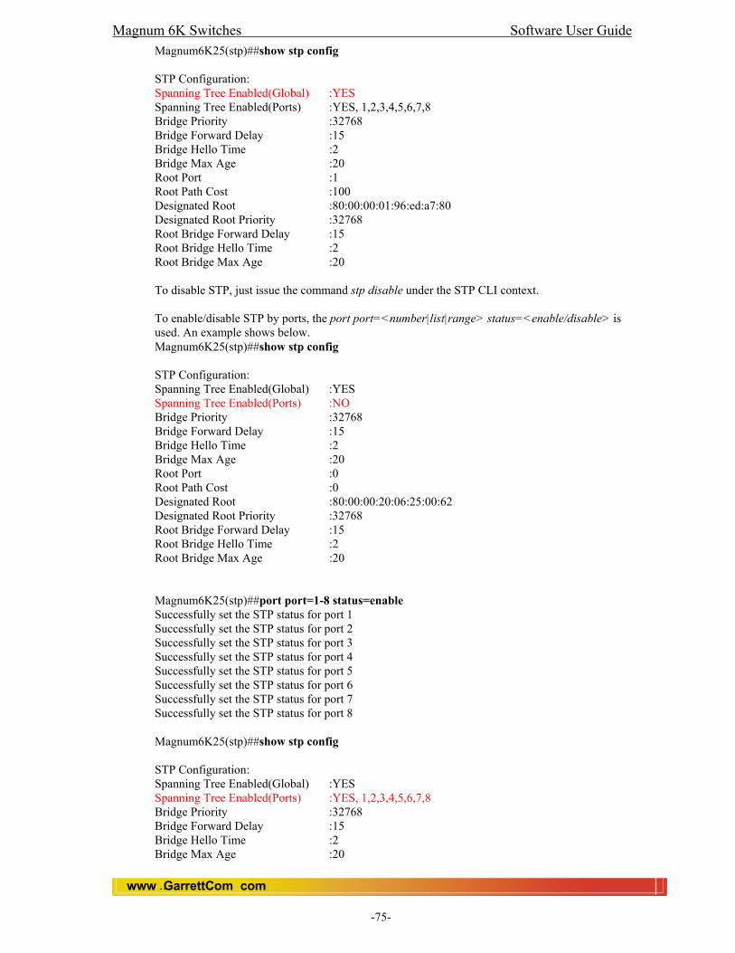
Magnum 6K Switches Software User Guide
www GarrettCom com..
-75-
Magnum6K25(stp)##show stp config STP Configuration: Spanning Tree Enabled(Global) :YES Spanning Tree Enabled(Ports) :YES, 1,2,3,4,5,6,7,8 Bridge Priority :32768 Bridge Forward Delay :15 Bridge Hello Time :2 Bridge Max Age :20 Root Port :1 Root Path Cost :100 Designated Root :80:00:00:01:96:ed:a7:80 Designated Root Priority :32768 Root Bridge Forward Delay :15 Root Bridge Hello Time :2 Root Bridge Max Age :20 To disable STP, just issue the command stp disable under the STP CLI context. To enable/disable STP by ports, the port port=<number|list|range> status=<enable/disable> is used. An example shows below. Magnum6K25(stp)##show stp config STP Configuration: Spanning Tree Enabled(Global) :YES Spanning Tree Enabled(Ports) :NO Bridge Priority :32768 Bridge Forward Delay :15 Bridge Hello Time :2 Bridge Max Age :20 Root Port :0 Root Path Cost :0 Designated Root :80:00:00:20:06:25:00:62 Designated Root Priority :32768 Root Bridge Forward Delay :15 Root Bridge Hello Time :2 Root Bridge Max Age :20 Magnum6K25(stp)##port port=1-8 status=enable Successfully set the STP status for port 1 Successfully set the STP status for port 2 Successfully set the STP status for port 3 Successfully set the STP status for port 4 Successfully set the STP status for port 5 Successfully set the STP status for port 6 Successfully set the STP status for port 7 Successfully set the STP status for port 8 Magnum6K25(stp)##show stp config STP Configuration: Spanning Tree Enabled(Global) :YES Spanning Tree Enabled(Ports) :YES, 1,2,3,4,5,6,7,8 Bridge Priority :32768 Bridge Forward Delay :15 Bridge Hello Time :2 Bridge Max Age :20
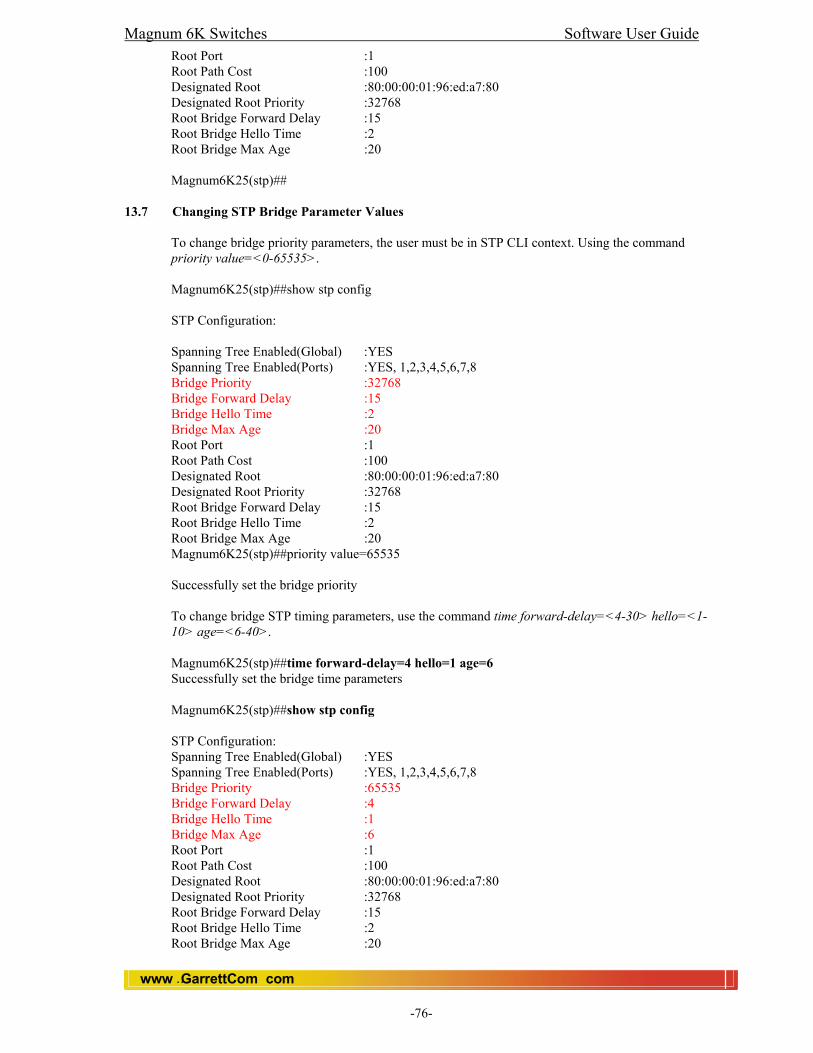
Magnum 6K Switches Software User Guide
www GarrettCom com..
-76-
Root Port :1 Root Path Cost :100 Designated Root :80:00:00:01:96:ed:a7:80 Designated Root Priority :32768 Root Bridge Forward Delay :15 Root Bridge Hello Time :2 Root Bridge Max Age :20 Magnum6K25(stp)##
13.7 Changing STP Bridge Parameter Values
To change bridge priority parameters, the user must be in STP CLI context. Using the command priority value=<0-65535>. Magnum6K25(stp)##show stp config STP Configuration: Spanning Tree Enabled(Global) :YES Spanning Tree Enabled(Ports) :YES, 1,2,3,4,5,6,7,8 Bridge Priority :32768 Bridge Forward Delay :15 Bridge Hello Time :2 Bridge Max Age :20 Root Port :1 Root Path Cost :100 Designated Root :80:00:00:01:96:ed:a7:80 Designated Root Priority :32768 Root Bridge Forward Delay :15 Root Bridge Hello Time :2 Root Bridge Max Age :20 Magnum6K25(stp)##priority value=65535 Successfully set the bridge priority To change bridge STP timing parameters, use the command time forward-delay=<4-30> hello=<1-10> age=<6-40>. Magnum6K25(stp)##time forward-delay=4 hello=1 age=6 Successfully set the bridge time parameters Magnum6K25(stp)##show stp config STP Configuration: Spanning Tree Enabled(Global) :YES Spanning Tree Enabled(Ports) :YES, 1,2,3,4,5,6,7,8 Bridge Priority :65535 Bridge Forward Delay :4 Bridge Hello Time :1 Bridge Max Age :6 Root Port :1 Root Path Cost :100 Designated Root :80:00:00:01:96:ed:a7:80 Designated Root Priority :32768 Root Bridge Forward Delay :15 Root Bridge Hello Time :2 Root Bridge Max Age :20

Magnum 6K Switches Software User Guide
www GarrettCom com..
-77-
Magnum6K25(stp)##
13.8 Changing STP Port Parameter Values
To change the STP port priority, use the command priority port=<number|list|range> value=<0-255> under the STP CLI context. Magnum6K25(stp)##show stp ports STP Port Configuration: ----------------------------------------------------------------------------------------------- Port# Type Priority Path Cost State Des. Bridge Des. Port ----------------------------------------------------------------------------------------------- 01 TP(10/100) 128 100 Forwarding 80:00:00:01:96:ed:a7:80 80:20 02 TP(10/100) 128 100 Disabled ff:ff:00:20:06:25:00:62 80:02 03 TP(10/100) 128 100 Disabled ff:ff:00:20:06:25:00:62 80:03 04 TP(10/100) 128 100 Disabled ff:ff:00:20:06:25:00:62 80:04 05 TP(10/100) 128 19 Forwarding ff:ff:00:20:06:25:00:62 80:05 06 TP(10/100) 128 100 Disabled ff:ff:00:20:06:25:00:62 80:06 07 TP(10/100) 128 19 Forwarding ff:ff:00:20:06:25:00:62 80:07 08 TP(10/100) 128 100 Disabled ff:ff:00:20:06:25:00:62 80:08 Magnum6K25(stp)##priority port=01 value=50 Successfully set the priority for port 1 To change STP port cost, use the command, use the cost port=<number|list|range> value=<0-65535> . Magnum6K25(stp)##cost port=1 value=200 Successfully set the path cost for port 1 Magnum6K25(stp)##show stp ports STP Port Configuration: ---------------------------------------------------------------------------------------------- Port# Type Priority Path Cost State Des. Bridge Des. Port ---------------------------------------------------------------------------------------------- 01 TP(10/100) 50 200 Forwarding 80:00:00:01:96:ed:a7:80 80:20 02 TP(10/100) 128 100 Disabled ff:ff:00:20:06:25:00:62 80:02 03 TP(10/100) 128 100 Disabled ff:ff:00:20:06:25:00:62 80:03 04 TP(10/100) 128 100 Disabled ff:ff:00:20:06:25:00:62 80:04 05 TP(10/100) 128 19 Forwarding ff:ff:00:20:06:25:00:62 80:05 06 TP(10/100) 128 100 Disabled ff:ff:00:20:06:25:00:62 80:06 07 TP(10/100) 128 19 Forwarding ff:ff:00:20:06:25:00:62 80:07 08 TP(10/100) 128 100 Disabled ff:ff:00:20:06:25:00:62 80:08
13.9 How STP Operates
The switch automatically senses port identity and type, and automatically defines port cost and priority for each type. The console interface allows you to adjust the Cost and Priority for each port. It also allows you to adjust the mode for each port and the global STP parameter values for the switch. While allowing only one active path through a network at any time, STP retains any redundant physical path to serve as a backup (blocked) path in case the existing active path fails. Thus, if an active path fails, STP automatically activates (unblocks) an available backup to serve as the new active path for as long as the original active path is down.

Magnum 6K Switches Software User Guide
www GarrettCom com..
-78-
13.10 Web: View and Configure STP Parameters
In the web browser interface: 1. Click on the [Configuration]. 2. Click on [Port]. 3. Click on [Settings]. 4. Select a port to modify 5. After you make the desired changes, click on [OK] button. 6. Click [Save] to save the configuration.
Magnum 6K Switches Software User Guide
www GarrettCom com..
-79-
14.0 Rapid Spanning Tree Protocol (RSTP)
Rapid Spanning Tree Protocol (RSTP) (IEEE 802.1w) is an evolution of the Spanning Tree Protocol (STP) (802.1D standard) and provides for faster spanning tree convergence after a topology change. Use spanning tree protocol to ensure that only one active path at a time exists between any two nodes on the network. In networks where there is more than one physical, active path between any two nodes, enabling spanning tree ensures a single active path between such nodes by blocking all redundant paths. Without spanning tree, having more than one active path between a pair of nodes causes loops in the network, which can result in duplication of messages, leading to a “broadcast storm” that can bring down the network. Note: User should enable spanning tree operation in any switch that is part of a redundant physical link (loop topology). (It is recommended that you do so on all switches belonging to a loop topology.) This topic is covered in more detail under chapter “Spanning Tree Protocol”.
14.1 How Spanning Tree Operates
The switch automatically senses port identity and type, and automatically defines spanning-tree parameters for each type, as well as parameters that apply across the switch. You can use the default values for these parameters, or adjust them as needed. While allowing only one active path through a network at any time, spanning tree retains any redundant physical path to serve as a redundant (blocked) path in case the existing active path fails. Thus, if an active path fails, spanning tree automatically activates (unblocks) an available redundant to serve as the new active path for as long as the original active path is down. In the factory default, spanning tree operation is disabled. If a redundant link (loop) exists between nodes in your network, user should enable the spanning tree operation of their choice.
14.3 RSTP Concepts
The 802.1d Spanning Tree Protocol was developed to allow the construction of robust networks that incorporate redundancy while pruning the active topology of the network to prevent loops. While STP is effective, it requires that frame transfer must halt after a link outage until all bridges in the network are sure to be aware of the new topology. Using the Spanning Tree Protocol (IEEE 802.1d) recommended values, this period lasts 30 seconds. Rapid Spanning Tree Protocol (IEEE 802.1w) is a further evolution of the 802.1d Spanning Tree Protocol. It replaces the settling period with an active handshake between bridges that guarantees topology information to be rapidly propagated through the network. RSTP converges in less than one second. RSTP also offers a number of other significant innovations, including: • Topology changes in STP must be passed to the root bridge before they can be propagated to the network. Topology changes in RSTP can be originated from and acted upon by any designated bridges, leading to more rapid propagation of address information. • STP recognizes one state, blocking, for ports that should not forward. RSTP explicitly recognizes two blocking roles, alternate and backup port roles, including them in computations of when to learn and forward. • STP relays configuration messages received on the root port out its designated ports. If an STP bridge fails to receive a message from its neighbor it cannot be sure where along the path to the root a failure occurred. RSTP bridges generate their own configuration messages, even if they fail to receive one from the root bridge. This leads to quicker failure detection. • RSTP offers edge port recognition, allowing ports at the edge of the network to forward frames immediately after activation while at the same time protecting them against loops. • An improvement to age configuration messages more quickly to prevent them from “going around in circles” in the event of a loop.
There are three RSTP states: Discarding, Learning and Forwarding. The discarding state is entered when the port is first taken into service. The port does not learn addresses in this state and does not participate in frame transfer. The port looks for STP traffic in order to determine its role in the network. When it is determined that the port will play an active part
Magnum 6K Switches Software User Guide
www GarrettCom com..
-80-
in the network, the state will change to Learning. The learning state is entered when the port is preparing to play an active member of the network. The port learns addresses in this state but does not participate in frame transfer. In a network of RSTP bridges the time spent in this state is usually quite short. RSTP bridges operating in STP compatibility mode will spend 6 to 40 seconds in this state. After ‘learning’ the bridge will place the port in the forwarding state. The port both learns addresses and participates in frame transfer while in this state.
14.4 Spanning Tree Options: RSTP (802.1w) and STP (802.1D) 14.4.1 RSTP (802.1w)
The IEEE 802.1D version of spanning tree (STP) can take a fairly long time to resolve all the possible paths and to select the most efficient path through the network. The IEEE 802.1w Rapid Reconfiguration Spanning Tree (RSTP) significantly reduces the amount of time it takes to establish the network path. The result is reduced network downtime and improved network robustness. In addition to faster network reconfiguration, RSTP also implements greater ranges for port path costs to accommodate the higher and higher connection speeds that are being implemented. RSTP is designed to be compatible with IEEE 802.1D STP, and GarrettCom recommends that you employ it in your network.
14.4.2 STP (802.1D)
The IEEE 802.1D version of spanning tree has been in wide use and can coexist in a network in which RSTP (802.1w) has been introduced. If your network currently uses 802.1D STP and you are not yet ready to implement RSTP, you can apply STP to the switch until such time as you are ready to move ahead with RSTP. STP offers the full range of STP features found in earlier product releases.
14.5 Transitioning from STP to RSTP
IEEE 802.1w RSTP is designed to be compatible with IEEE 802.1D STP. Even if all the other devices in your network are using STP, you can enable RSTP on your switch, and even using the default configuration values, your switch will interoperate effectively with the STP devices. If any of the switch ports are connected to switches or bridges on your network that do not support RSTP, RSTP can still be used on this switch. RSTP automatically detects when the switch ports are connected to non-RSTP devices in the spanning tree and communicates with those devices using 802.1D STP BPDU packets. Because RSTP is so much more efficient at establishing the network path, it is highly recommended that all your network devices be updated to support RSTP. RSTP offers convergence times of less than one second under optimal circumstances. To make the best use of RSTP and achieve the fastest possible convergence times, though, there are some changes that you should make to the RSTP default configuration.
Note Under some circumstances, it is possible for the rapid state transitions employed by RSTP to result in an increase in the rates of frame duplication and disordering in the switched LAN. In order to allow RSTP switches to support applications and protocols that may be sensitive to frame duplication and disordering, setting the Force Protocol Version parameter to STP-compatible allows RSTP to be operated with the rapid transitions disabled. The value of this parameter applies to all ports on the switch. As indicated above, one of the benefits of RSTP is the implementation of a larger range of port path costs, which accommodates higher network speeds. New default values have also been implemented for the path costs associated with the different network speeds. This can create some incompatibility between devices running the older 802.1D STP and your switch running RSTP.
14.6 Configuring Rapid Reconfiguration Spanning Tree (RSTP)
This section describes the operation of the IEEE 802.1w Rapid Spanning Tree Protocol (RSTP). Note: The default switch configuration has active spanning tree (STP) and disabled.

Magnum 6K Switches Software User Guide
www GarrettCom com..
-81-
14.6.1 Optimizing the RSTP Configuration
To optimize the RSTP configuration on your switch, follow these steps 1. Set the switch to support RSTP (STP is the default): Syntax: set stp type=rstp 2. Save and Reboot the switch. 3. Enable RSTP Spanning Tree Syntax: rstp enable 4. Set the “point-to-point” value to off on all ports that are connected to shared LAN segments (that is, to connections to hubs). The default value is auto. Syntax: port port=<number|list|range> p2p= off 5. Set the “edge-port” value to YES for all ports connected to other switches, bridges, and hubs. Syntax: port port=<number|list|range> edge=enable 6. Set the “migration” value to YES for all ports that are connected to devices that are known to be running IEEE 802.1D spanning tree. Syntax: port port=<number|list|range> migration=enable
14.7 CLI 14.7.1 Main Context Commands
Switch between STP and RSTP Syntax: set stp type=<stp|rstp> Magnum6K25# set stp type=rstp This command sets the current STP to either STP or RSTP. Note: This requires a save and a reboot for the new STP/RSTP to take effect. To see the active STP (STP or RSTP) Syntax: show active-stp Magnum6K25# show active-stp This command shows which one (STP or RSTP) is currently active. e.g., RSTP is currently active. To see the current configuration Syntax: show stp config Magnum6K25#show stp config

Magnum 6K Switches Software User Guide
www GarrettCom com..
-82-
To see the current status Syntax: show stp ports Magnum6K25#show stp ports
14.7.2 RSTP Context Commands
This context contains all the RSTP related commands and can only be executed when RSTP is active. If RSTP is not active, trying to execute these commands will create an error message. Most of the commands are very similar to STP, but may have extra parameters.
Go to RSTP configuration mode to configure RSTP. Syntax: rstp <enter> Magnum6K25#rstp <enter> Magnum6K25(rstp)## To Enable RSTP (Global) Syntax: rstp <enable | disable> Magnum6K25(rstp)## rstp enable This command enables or disables the RSTP globally. To Enable RSTP (Per Port Basis) Syntax: port port=<number|list|range> [status=<enable/disable>] [migration=<enable|disable>] [edge=<enable|disable>] [p2p=<enable|disable>]
port – a port or list of ports status – enable or disable RSTP on that port(s). migration – enable or disable migration on the port(s). edge - set the current port as an edge port (end station) p2p - set the current port as point to point.
Note: By default all ports are enable for RSTP. User can disable the specific port for RSTP. Magnum6K25(rstp)##Port port=15 status=disable Magnum6K25(rstp)##show stp ports
To Force the Protocol Syntax: forceversion <stp|rstp> This command sets the stp or RSTP compatibility mode. Syntax: show-forceversion User can see the current forced version using this command. Magnum6K25(rstp)##show-forceversion Force Version : Normal RSTP
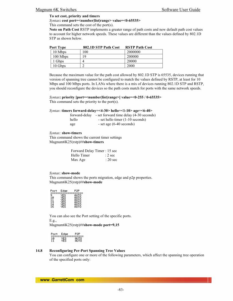
Magnum 6K Switches Software User Guide
www GarrettCom com..
-83-
To set cost, priority and timers Syntax: cost port=<number|list|range> value=<0-65535> This command sets the cost of the port(s). Note on Path Cost RSTP implements a greater range of path costs and new default path cost values to account for higher network speeds. These values are different than the values defined by 802.1D STP as shown below.
Port Type 802.1D STP Path Cost RSTP Path Cost
10 Mbps 100 2000000 100 Mbps 19 200000 1 Gbps 4 20000 10 Gbps 2 2000
Because the maximum value for the path cost allowed by 802.1D STP is 65535, devices running that version of spanning tree cannot be configured to match the values defined by RSTP, at least for 10 Mbps and 100 Mbps ports. In LANs where there is a mix of devices running 802.1D STP and RSTP, you should reconfigure the devices so the path costs match for ports with the same network speeds. Syntax: priority [port=<number|list|range>] value=<0-255 / 0-65535> This command sets the priority to the port(s). Syntax: timers forward-delay=<4-30> hello=<1-10> age=<6-40>
forward-delay - set forward time delay (4-30 seconds) hello - set hello timer (1-10 seconds) age - set age (6-40 seconds)
Syntax: show-timers This command shows the current timer settings Magnum6K25(rstp)##show-timers
Forward Delay Timer : 15 sec Hello Timer : 2 sec Max Age : 20 sec
Syntax: show-mode This command shows the ports migration, edge and p2p properties. Magnum6K25(rstp)##show-mode
You can also see the Port setting of the specific ports. E.g., Magnum6K25(rstp)##show-mode port=9,15
14.8 Reconfiguring Per-Port Spanning Tree Values
You can configure one or more of the following parameters, which affect the spanning tree operation of the specified ports only:

Magnum 6K Switches Software User Guide
www GarrettCom com..
-84-
14.8.1 Per-Port RSTP Parameters Parameter Default Description
edge-port Yes This identifies ports that are connected to end nodes. During spanning tree establishment, these ports transition immediately to the Forwarding state. Disable this feature on all switch ports that are connected to another switch, or bridge, or hub. Use the “no” option on the spanning tree command to disable edge-port.
migration Yes Ports with migration set to true are forced to send out RSTP BPDUs for 3 seconds. This allows for switches that are running RSTP to establish their connection quickly and for switches running 802.1D STP to be identified. If the whole-switch parameter Force-Version is set to “stp-compatible”, the migration setting is ignored and STP BPDUs are sent out all ports.
path-cost 10 Mbps – 2 000 000 100 Mbps – 200 000 1 Gbps – 20 000 Assigns an individual port cost that the switch uses to determine which ports are the forwarding ports. The range is 1 to 200,000,000 or auto. By default, this parameter is automatically determined by the port type, as shown by the different default values. If you have previously configured a specific value for this parameter, you can issue the command with the auto option to restore the automatic setting feature. Please see the Note on Path Cost on page 14-15 for information on compatibility with devices running 802.1D STP for the path cost values.
point-to-point(p2p) Auto This parameter is used to tell the port if it is connected to a point-to-point link . Default parameter is auto and the switch will automatically set the force-false value on all ports that it detects are not running at full duplex. All connections to hubs are not full duplex. You can also set this parameter to ON, such as to another switch or bridge or to an end node (force-true). This parameter should be set to OFF (force-false) for all ports that are connected to a hub, which is a shared LAN segment.
priority 128 This parameter is used by RSTP to determine the port(s) to use for forwarding.The port with the lowest number has the highest priority. The range is 0 to 240, but you configure the value by entering a multiple of 16. You enter a value in the range 0 - 15. The default value of 128.
Magnum 6K Switches Software User Guide
www GarrettCom com..
-85-
15.0 Port-Based Virtual LANs (Static VLANs) A VLAN is a group of ports designated by the switch as belonging to the same broadcast domain. (That is, all ports carrying traffic for a particular subnet address would normally belong to the same VLAN.) Note: This section describes static VLANs, which are VLANs you manually configure with a name, VLAN ID (VID), and port assignments. Using a VLAN, you can group users by logical function instead of physical location. This helps to control bandwidth usage by allowing you to group high-bandwidth users on low-traffic segments and to organize users from different LAN segments according to their need for common resources. By default, the 6K switches are VLAN (Port based) enabled and allow up to 32 VLANs. The port-based nature of the configuration allows interoperation with older switches that require a separate port for each VLAN.
15.1 General Use and Operation Port-based VLANs are typically used to enable broadcast traffic reduction and to increase security. A group of network users assigned to a VLAN form a broadcast domain that is separate from other VLANs that may be configured on a switch. Packets are forwarded only between ports that are designated for the same VLAN. Thus, all ports carrying traffic for a particular subnet address should be configured to the same VLAN. Cross-domain broadcast traffic in the switch is eliminated and bandwidth is saved by not allowing packets to flood out all ports. An external router is required to enable separate VLANs on a switch to communicate with each other.
15.2 VLAN Support and the Default VLAN In the factory default configuration, VLAN support is enabled and all ports on the switch belong to the default VLAN (named DEFAULT-VLAN). This places all ports in the switch into one physical broadcast domain. You can partition the switch into multiple virtual broadcast domains by adding one or more additional VLANs and moving ports from the default VLAN to the new VLANs. (The switch supports up to 32 VLANs.) You can change the name of the default VLAN, but you cannot change the default VLAN’s VID (which is always “1”). Although you can remove all ports from the default VLAN, this VLAN is always present. The Magnum 6K Switches Port Based VLAN operates by restricting the broadcast and multicast traffic between the ports. A packet with a broadcast address or with an unknown destination address is forwarded only to ports that share VLAN membership with the source port. Unnecessary repeating of broadcast packets is thus avoided, conserving bandwidth. Packets destined to known addresses are forwarded normally. Note: Always start all VLANs before editing the default Vlan. Syntax: start vlan=all Then, edit id=<vlan Id> [name=<vlan name>] port=<number|list|range> To display the current VLAN, use the CLI show vlan command. Syntax: show vlan type=port
15.3 General Steps for Using VLANs
1. Plan your VLAN strategy and create a map of the logical topology that will result from configuring VLANs. Include consideration for the interaction between VLANs. 2. Configure at least one VLAN in addition to the default VLAN. 3. Assign the desired switch ports to the new VLAN(s).

Magnum 6K Switches Software User Guide
www GarrettCom com..
-86-
Notes on Using VLANs • You can rename the default VLAN, but you cannot change its VID (1) or delete it
from the switch. • Any ports not specifically assigned to another VLAN will remain assigned to the
DEFAULT-VLAN. • Changing the number of VLANs supported on the switch requires the SAVE
command.
15.4 CLI: Configuring VLAN Parameters
In the factory default state, all ports on the switch belong to the default VLAN (DEFAULT-VLAN) and are in the same broadcast/multicast domain. You can configure up to 31 additional static VLANs by adding new VLAN names, and then assigning one or more ports to each VLAN. (The switch accepts a maximum of 32 VLANs, including the default VLAN ).
NOTE: Magnum 6K support one type of VLAN at a time. The user has to set the VLAN type before configuration.
Steps: To set the type of Vlan that you are going to use. Syntax: set vlan type=<port|tag|mac|none> Magnum6K25#set vlan type=port VLAN set to Port-based.
Go to Configuration mode Syntax: configure vlan type=port OR vlan type=port Magnum6K25#vlan type=port Magnum6K25(port-vlan)##
Add VLAN Syntax: add id=<vlan Id> [name=<vlan name>] port=<number|list|range>
Magnum6K25(port-vlan)## add id=2 name=test port=1-10
Start Vlan Syntax: start vlan=<name|number|list|range> Magnum6K25(port-vlan)## start vlan=all
Save the configuration Syntax: save Magnum6K25(port-vlan)##save
Saving current configuration... Configuration saved
15.4.1 Displaying the Switch’s VLAN Configuration.
The next command lists the VLANs currently running in the switch, with VID, VLAN name, and VLAN status. Magnum6K25# show vlan type=port VLAN ID : 1 Name : Default VLAN Status : Active ======================== PORT | STATUS ======================== 1 | DOWN 2 | DOWN 3 | DOWN 4 | DOWN
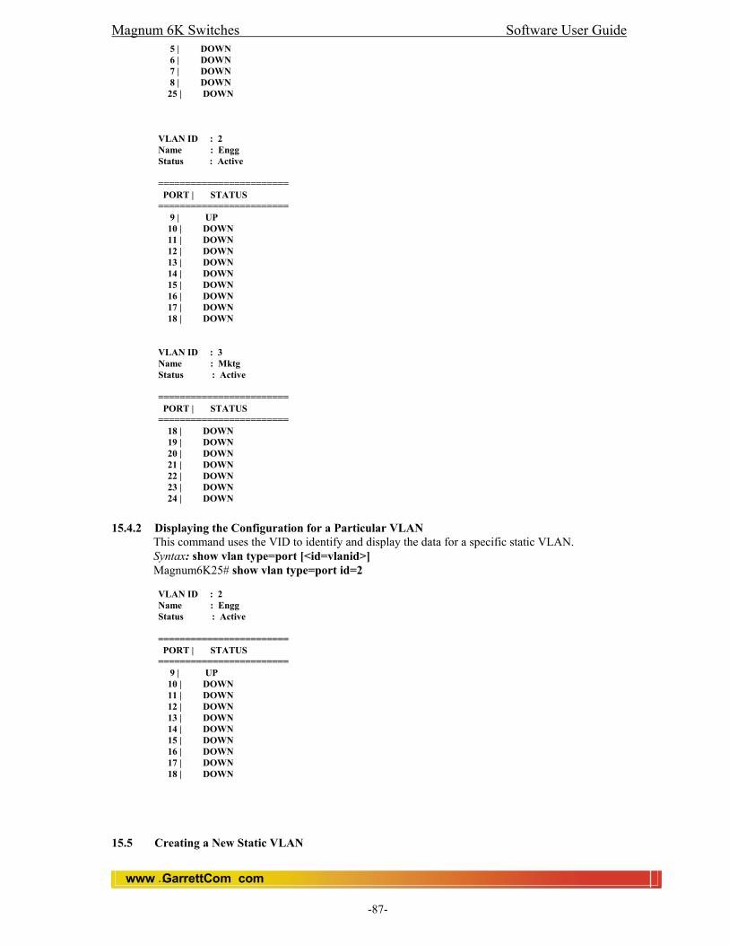
Magnum 6K Switches Software User Guide
www GarrettCom com..
-87-
5 | DOWN 6 | DOWN 7 | DOWN 8 | DOWN 25 | DOWN VLAN ID : 2 Name : Engg Status : Active ======================== PORT | STATUS ======================== 9 | UP 10 | DOWN 11 | DOWN 12 | DOWN 13 | DOWN 14 | DOWN 15 | DOWN 16 | DOWN 17 | DOWN 18 | DOWN VLAN ID : 3 Name : Mktg Status : Active ======================== PORT | STATUS ======================== 18 | DOWN 19 | DOWN 20 | DOWN 21 | DOWN 22 | DOWN 23 | DOWN 24 | DOWN
15.4.2 Displaying the Configuration for a Particular VLAN
This command uses the VID to identify and display the data for a specific static VLAN. Syntax: show vlan type=port [<id=vlanid>] Magnum6K25# show vlan type=port id=2 VLAN ID : 2 Name : Engg Status : Active ======================== PORT | STATUS ======================== 9 | UP 10 | DOWN 11 | DOWN 12 | DOWN 13 | DOWN 14 | DOWN 15 | DOWN 16 | DOWN 17 | DOWN 18 | DOWN
15.5 Creating a New Static VLAN
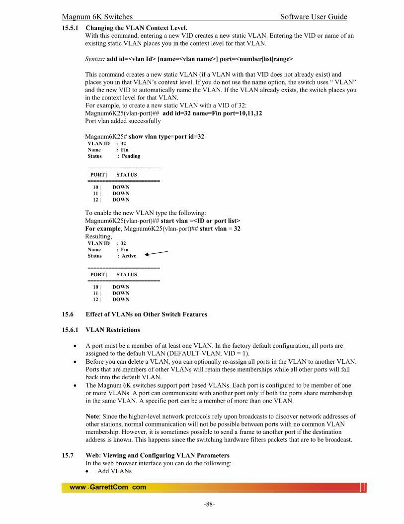
Magnum 6K Switches Software User Guide
www GarrettCom com..
-88-
15.5.1 Changing the VLAN Context Level. With this command, entering a new VID creates a new static VLAN. Entering the VID or name of an existing static VLAN places you in the context level for that VLAN. Syntax: add id=<vlan Id> [name=<vlan name>] port=<number|list|range> This command creates a new static VLAN (if a VLAN with that VID does not already exist) and places you in that VLAN’s context level. If you do not use the name option, the switch uses “ VLAN” and the new VID to automatically name the VLAN. If the VLAN already exists, the switch places you in the context level for that VLAN. For example, to create a new static VLAN with a VID of 32: Magnum6K25(vlan-port)## add id=32 name=Fin port=10,11,12 Port vlan added successfully Magnum6K25# show vlan type=port id=32 VLAN ID : 32 Name : Fin Status : Pending ======================== PORT | STATUS ======================== 10 | DOWN 11 | DOWN 12 | DOWN To enable the new VLAN type the following: Magnum6K25(vlan-port)## start vlan =<ID or port list> For example, Magnum6K25(vlan-port)## start vlan = 32 Resulting, VLAN ID : 32 Name : Fin Status : Active ======================== PORT | STATUS ======================== 10 | DOWN 11 | DOWN 12 | DOWN
15.6 Effect of VLANs on Other Switch Features 15.6.1 VLAN Restrictions
• A port must be a member of at least one VLAN. In the factory default configuration, all ports are
assigned to the default VLAN (DEFAULT-VLAN; VID = 1). • Before you can delete a VLAN, you can optionally re-assign all ports in the VLAN to another VLAN.
Ports that are members of other VLANs will retain these memberships while all other ports will fall back into the default VLAN.
• The Magnum 6K switches support port based VLANs. Each port is configured to be member of one or more VLANs. A port can communicate with another port only if both the ports share membership in the same VLAN. A specific port can be a member of more than one VLAN. Note: Since the higher-level network protocols rely upon broadcasts to discover network addresses of other stations, normal communication will not be possible between ports with no common VLAN membership. However, it is sometimes possible to send a frame to another port if the destination address is known. This happens since the switching hardware filters packets that are to be broadcast.
15.7 Web: Viewing and Configuring VLAN Parameters
In the web browser interface you can do the following: • Add VLANs

Magnum 6K Switches Software User Guide
www GarrettCom com..
-89-
• Rename VLANs • Remove VLANs • Configure GVRP security • Select a active VLAN
15.7.1 To configure static VLAN port parameters
1. Click on the [Configuration] tab. 2. Click on [VLAN]. 3. Click on desired VLAN, Port or Tag. 4. Click on [Add/Delete] button. 5. After you make the desired changes, click on [OK] button. 6. Click [Save] to save the configuration. For web-based Help on how to use the web browser interface screen, click on the [Help] button provided on the web browser screen.

Magnum 6K Switches Software User Guide
www GarrettCom com..
-90-
16.0 TAG Based VLAN 16.1 Introduction
TAG based VLANs are used to filter packets arriving at a particular port or set of ports. The filtering is based on the TAG information contained in the packet. Hence, we can drop or allow through packets arriving on a set of ports based on the source TAG information contained in the packets.
16.2 VLAN Tagging Information VLAN tagging enables traffic from more than one VLAN to use the same port. (Even when two or more VLANs use the same port they remain as separate domains and cannot receive traffic from each other without going through an external router.) As mentioned earlier, a “tag” is simply a unique VLAN identification number (VLAN ID, or VID) assigned to a VLAN at the time that you configure the VLAN name in the switch. In the Magnum 6K switches, the tag can be any number from 1 to 4095 that is not already assigned to a VLAN. When you subsequently assign a port to a given VLAN, you must implement the VLAN tag (VID) if the port will carry traffic for more than one VLAN. Otherwise, the port VLAN assignment can remain “untagged” because the tag is not needed. On a given switch, this means you should use the “Untagged” designation for a port VLAN assignment where the port is connected to a non 802.1Q-compliant device or is assigned to only one VLAN. Use the “Tagged” designation on at least one of the VLAN’s when the port is assigned to more than one VLAN or the port is connected to a device that does comply with the 802.1Q standard.
Ports 1-6: Untagged Port 7: Red VLAN Untagged Green VLAN Tagged
Ports 1-4: Untagged Port 5: Red VLAN Untagged Example of Tagged and Untagged VLAN Port Assignments
For example, if port 7 on an 802.1Q-compliant switch is assigned to only the Red VLAN, the assignment can remain “untagged” because the port will forward traffic only for the Red VLAN. However, if both the Red and Green VLANs are assigned to port 7, then at least one of those VLAN assignments must be “tagged” so that Red VLAN traffic can be distinguished from Green VLAN traffic. The above illustration shows this concept.
1
1
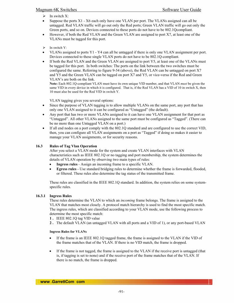
Magnum 6K Switches Software User Guide
www GarrettCom com..
-91-
In switch X: • Suppose the ports X1 - X6 each only have one VLAN per port. The VLANs assigned can all be
untagged. Red VLAN traffic will go out only the Red ports; Green VLAN traffic will go out only the Green ports, and so on. Devices connected to these ports do not have to be 802.1Qcompliant.
• However, if both the Red VLAN and the Green VLAN are assigned to port X7, at least one of the VLANs must be tagged for this port.
In switch Y:
• VLANs assigned to ports Y1 - Y4 can all be untagged if there is only one VLAN assignment per port. Devices connected to these single VLAN ports do not have to be 802.1Q-compliant.
• If both the Red VLAN and the Green VLAN are assigned to port Y5, at least one of the VLANs must be tagged for this port. In both switches: The ports on the link between the two switches must be configured the same. Referring to figure 9-54 (above), the Red VLAN can be untagged on port X7 and Y5 and the Green VLAN can be tagged on port X7 and Y5, or vice-versa if the Red and Green VLAN’s are both on the link. Note: Each 802.1Q-compliant VLAN must have its own unique VID number, and that VLAN must be given the same VID in every device in which it is configured. That is, if the Red VLAN has a VID of 10 in switch X, then 10 must also be used for the Red VID in switch Y.
VLAN tagging gives you several options:
• Since the purpose of VLAN tagging is to allow multiple VLANs on the same port, any port that has only one VLAN assigned to it can be configured as “Untagged” (the default).
• Any port that has two or more VLANs assigned to it can have one VLAN assignment for that port as “Untagged”. All other VLANs assigned to the same port must be configured as “Tagged”. (There can be no more than one Untagged VLAN on a port.)
• If all end nodes on a port comply with the 802.1Q standard and are configured to use the correct VID, then, you can configure all VLAN assignments on a port as “Tagged” if doing so makes it easier to manage your VLAN assignments, or for security reasons.
16.3 Rules of Tag Vlan Operation
After you select a VLAN mode for the system and create VLAN interfaces with VLAN characteristics such as IEEE 802.1Q or no tagging and port membership, the system determines the details of VLAN operation by observing two main types of rules: • Ingress rules - Assign an incoming frame to a specific VLAN. • Egress rules - Use standard bridging rules to determine whether the frame is forwarded, flooded,
or filtered. These rules also determine the tag status of the transmitted frame.
These rules are classified in the IEEE 802.1Q standard. In addition, the system relies on some system-specific rules.
16.3.1 Ingress Rules These rules determine the VLAN to which an incoming frame belongs. The frame is assigned to the VLAN that matches most closely. A protocol match hierarchy is used to find the most specific match. The ingress rules, which are classified according to your VLAN mode, use the following process to determine the most specific match: 1 . IEEE 802.1Q tag VID value 2 . The default VLAN (an untagged VLAN with all ports and a VID of 1), or any port-based VLAN Ingress Rules for VLANs
• If the frame is an IEEE 802.1Q tagged frame, the frame is assigned to the VLAN if the VID of the frame matches that of the VLAN. If there is no VID match, the frame is dropped.
• If the frame is not tagged, the frame is assigned to the VLAN if the receive port is untagged (that is, if tagging is set to none) and if the receive port of the frame matches that of the VLAN. If there is no match, the frame is dropped.

Magnum 6K Switches Software User Guide
www GarrettCom com..
-92-
16.3.2 Egress Rules These rules determine whether the outgoing frame is forwarded, filtered (dropped), or flooded; they also determine the frame's tag status. The frame is forwarded out of the port in the VID 2 VLAN (where the address is known) and with the tag status of that port.
Standard Bridging Rules for Outgoing Frames The frame is handled according to these bridging rules: If the transmit port is tagged and is not a member of the assigned VLAN, the frame is dropped. If the frame's destination address matches an address that was learned on the receive port, it is filtered (dropped). If the frame's destination address matches an address that was learned on a port other than the receive port, it is forwarded to that port. If a frame with an unknown, multicast, or broadcast destination address is received, then it is flooded (that is, forwarded to all ports on the VLAN that is associated with the frame, except the port on which it was received). If the frame's destination address matches a MAC address of one of the bridge's ports, it is further processed, not forwarded immediately. This type of frame is a management/configuration frame, such as a SNMP get/set PDU, Administration Console Telnet packet, or a Web Management Interface http packet. Tag Status Rules After the VLAN and the transmit ports are determined for the frame, the tag status rules determine whether the frame is transmitted with an IEEE 802.1Q tag: • For each port on which a frame is to be transmitted, if that port is tagged for the VLAN that is
associated with the frame, transmit the frame as a tagged frame. • For each port on which a frame is to be transmitted, if that port is not tagged for the VLAN that is
associated with the frame, transmit the frame as an untagged frame
16.4 CLI Magnum 6K Switches support one type of VLAN at a time. The user has to set the VLAN type before configuration. Magnum6K25# set vlan type=<port|mac|tag|none> For Tag VLAN, Magnum6K25# set vlan type=tag Than, go to Vlan configuration mode by typing, Magnum6K25# vlan type=tag To add a TAG based VLAN we use the following command: Magnum6K25(tag-vlan)## add id=<vlan Id> [name=<vlan name>] port=<number|list|range> where,
id is a valid VLAN ID. Its value has to be between 1 and 4095. name is an optional field which is used to name a VLAN. port is a valid range/list of ports or a single port which is to be added to the VLAN.
Note: When a new TAG VLAN is added, the VLAN’s state is set to ‘pending’, to activate the VLAN, use the start command described below.
To delete a TAG VLAN use the following command: Magnum6K25(tag-vlan)## delete vlan=<name|number|list|range> where,
vlan is the name or VLAN ID which is to be deleted. This field also accepts range of VLAN ID values. Note: An active VLAN cannot be deleted. The VLAN has to be stopped before it can be deleted. Only VLAN’s in pending state can be deleted. To edit/change the VLAN settings use the following command: Magnum6K25(tag-vlan)##editid=<vlanId>[name=<vlanname>] port=<number|list|range> where,
id is an exisiting VLAN ID.

Magnum 6K Switches Software User Guide
www GarrettCom com..
-93-
name is an optional field which is the name of the VLAN. port is valid range/list of ports or a single port.
Note: An active VLAN cannot be edited. The VLAN has to be stopped before it can be edited. Only VLAN’s in pending state can be edited. To start/activate a VLAN use the following command: Magnum6K25(tag-vlan)## start vlan=<all|name|number|list|range> where,
vlan is the name or VLAN ID which is to be started/activated. This field also accepts range of VLAN ID values. To activate all the ‘pending’ VLAN’s, use ‘all’ instead of VLAN ID’s or VLAN name.
Note: Starting VLAN(s) will put them in active state. To stop a VLAN use the following command: Magnum6K25(tag-vlan)##stop vlan=<all|name|number|list|range> where,
vlan is the name or VLAN ID which is to be stopped. This field also accepts range of VLAN ID values. To stop all the ‘active’ VLAN’s, use ‘all’ instead of VLAN ID’s or VLAN name.
Note: Stopping VLAN(s) will put them in pending state. To set the ingress for a set of ports use the following command: Note: If you are setting Ingress or Egress rules remotely (Telnet, SNMP etc), then please start the Vlan first. Otherwise, you would lock out yourself from the Vlan. Magnum6K25(tag-vlan)## set-ingress port=<number|list|range> pvid=<number> action=<enable|disable> where,
port is valid range/list of ports or a single port. pvid is the valid Port VLAN ID. Its value can be between 1 and 4095. action is used to enable or disable ingress on that set of ports.
To set the egress rules for a set of ports in a particular TAG VLAN use the following command: Magnum6K25(tag-vlan)## set-egress vlan=<number> port=<number|list|range> status=<tagged|untagged> where,
vlan is the VLAN ID whose ports egress value has to be changed. port is the port or list/range of ports who are members of the VLAN ID mentioned above. status is the egress status for the ports. It can be either tagged or untagged.
To see the list of VLAN’s use the following command. Magnum6K25(tag-vlan)##show vlan type=<port|tag|mac> [<id=vlanid>] where,
type is the type of VLAN, here it has to be tag. Id is optional, and is used to see information about a particular VLAN, if this field is not entered, the entire list of TAG based VLAN’s is shown.
Note: VLAN’s that are still pending don’t have their egress setting set in the hardware. Only when the VLAN is activated, the egress settings are set in the hardware. Hence to see the list of ports which are set to tagged use the ‘show-egress’ command because show vlan will only show ports whose egress settings are set in the hardware. To see the ports and their ingress values use the following command: Magnum6K25(tag-vlan)## show-ingress [ports=<number|list|range>] ports is the port or list/range of ports whose ingress value has to be shown. This field is optinal and if it is not entered, the entire list of ports and their respective ingress values are shown. To see the ports which are tagged (whose egress values are set or to be set) use the following command: Magnum6K25(tag-vlan)## show-egress Note: Egress settings are updated only when the VLAN is set to active state; hence, this command shows the list of ports, which are set to egress, and their corresponding VLAN state. VLAN’s that are still in pending state do not have their egress set in the hardware.

Magnum 6K Switches Software User Guide
www GarrettCom com..
-94-
16.5 New CLI The set-ingress, set-egress, show-ingress and show-egress commands are deprecated. Two new commands viz. set-port and show-port take their place. Magnum6K25(tag-vlan)##set-port Usage: set-port port=<number|list|range> default id=<number> set-port port=<number|list|range> filter status=<enable|disable> set-port port=<number|list|range> tagging id=<number> status=<tagged|untagged> set-port port=<number|list|range> join id=<number> set-port port=<number|list|range> leave id=<number> Note: The old commands will still work, but it will give a message that it is deprecated. set-port port=<port> default id=<vlan> will set the default vlan id (termed PVID in previous versions). Default vlan id is the vlan id assigned to the untagged packets received on that port. set-port port=<port> filter status=<enable|disable> will enable or disable the vlan filtering function. When enabled, the switch will drop the packets coming in through a port if the port is not a member of the vlan of the packet. For example, if port 1 is a member of vlans 10,20 and 30, and vlan filter is enabled on port 1, if a packet with vlan id 40 arrives at port 1 it will be dropped. set-port port=<number|list|range> tagging id=<number> status=<tagged|untagged> will define the outgoing packets from a port will be tagged or untagged. This definition is on a per VLAN basis. For example the command set-port port=1 tagging id=10 status=tagged will instruct the switch to tag all packets belonging to vlan 10 that goes out of port 1. set-port port=<number|list|range> join id=<number> will add the specified port(s) to the specified vlan id. This command will work with active or pending vlans. set-port port=<number|list|range> leave id=<number> will delete the port(s) from the specified vlan id. This command will work with active or pending vlans. show-port [port=<port|list|range>] will show all parameters related to tag vlan for the list of ports. If the port parameter is omitted, it will display all ports. Magnum6K25(tag-vlan)##show-port VLAN Port Status. Port 1 Default Vlan : 1 Filter Status : ENABLED. VLAN Memberships: Vlan: 1 Status: Active UNTAGGED Port 2 Default Vlan : 1 Filter Status : ENABLED. VLAN Memberships: Vlan: 1 Status: Active UNTAGGED Port 3 Default Vlan : 1 Filter Status : ENABLED. VLAN Memberships: Vlan: 1 Status: Active UNTAGGED

Magnum 6K Switches Software User Guide
www GarrettCom com..
-95-
16.6 Web: View and Configure Tag-Vlan Parameters In the web browser interface: 1. Click on the [Configuration]. 2. Click on [Vlan]. 3. Click on [Tag-Based]. 4. Click on [Add] to add Vlan. 5. Enter Vlan ID, Vlan Name and select Port Members. 6. After you make the desired changes, click on [OK] button. 7. Click [Save] to save the configuration.
Similarly, You can delete the Vlan. 1. Click on the [Configuration]. 2. Click on [Vlan]. 3. Click on [Tag-Based]. 4. Click on [Delete] to delete Vlan. 5. Select Vlan ID to delete from the drop down list. 6. After you make the desired changes, click on [OK] button. 7. Click [Save] to save the configuration. This menu also gives the facility to configure Ingress and Egress rules by clicking [Ingress] or [Egress] button. To view Ingress or Egress Rules (Filter) 1. Click on the [Configuration]. 2. Click on [Vlan]. 3. Click on [Ingress] or [Egress] Filter. It will show the Ingress and Egress rules.

Magnum 6K Switches Software User Guide
www GarrettCom com..
-96-
17.0 GVRP 17.1 GVRP (GARP VLAN Registration Protocol)
The above is an application of the Generic Attribute Registration Protocol (GARP). GVRP is defined in the IEEE 802.1Q standard, and GARP is defined in the IEEE 802.1P standard. Note: To understand and use GVRP you must have a working knowledge of 802.1Q VLAN tagging. (See “Tag-Based Virtual LANs (Static VLANs)” ). GVRP uses “GVRP Bridge Protocol Data Units” (“GVRP BPDUs”) to “advertise” static VLANs. In this manual, a GVRP BPDU is termed an advertisement. GVRP enables the 6K Switch to dynamically create 802.1Q-compliant VLANs on links with other devices running GVRP. This enables the switch to automatically create VLAN links between GVRP-aware devices. (A GVRP link can include intermediate devices that are not GVRP-aware.) This operation reduces the chances for errors in VLAN configuration by automatically providing VLAN ID (VID) consistency across the network. That is, you can use GVRP to propagate VLANs to other GVRP-aware devices instead of manually having to set up VLANs across your network. After the switch creates a dynamic, you can also use GVRP to dynamically enable port membership in static VLANs configured on a switch. Note: There must be one common VLAN (that is, one common VID) connecting all of the GVRP-aware devices in the network to carry GVRP packets. GarrettCom recommends the default VLAN (DEFAULT_VLAN; VID = 1), which is automatically enabled and configured as untagged on every port of the Magnum 6K switches). That is, on ports used for GVRP links, leave the default VLAN set to Untagged and configure other static VLANs on the same ports as either Tagged, Forbid. (Forbid option described under “Per-Port Options for Dynamic VLAN Advertising and Joining”.
17.2 General Operation
A GVRP-enabled port with a Tagged or Untagged static VLAN sends advertisements (BPDUs, or Bridge Protocol Data Units) advertising the VLAN (actually, its VID). Another GVRP-aware port receiving the advertisements over a link can dynamically join the advertised VLAN. All dynamic VLANs operate as Tagged VLANs. Also, a GVRP-enabled port can forward an advertisement for a VLAN it learned about from other ports on the same switch. However, the forwarding port will not itself join that VLAN until an advertisement for that VLAN is received on that specific port. Core switch with static VLANs (VID= 1, 2, & 3). Port 2 is a member of VIDs 1, 2, & 3. 1. Port 2 advertises VIDs 1, 2,& 3. 2. Port 1 receives advertisement of VIDs 1, 2, & 3 AND becomes a member of VIDs 1, 2, & 3. 3. Port 3 advertises VIDs 1, 2, & 3, but port 3 is NOT a member of VIDs 1, 2, & 3 at this point. 4. Port 4 receives advertisement of VIDs 1, 2, & 3 AND becomes a member of VIDs 1, 2, & 3. 5. Port 5 advertises VIDs 1, 2,& 3, but port 5 is NOT a member of VIDs 1, 2, & 3 at this point. Port 6 is statically configured to be a member of VID 3. 6. Port 6 advertises VID 3. 7. Port 5 receives advertisement 8. Port 4 advertises VID 3. 9. Port 3 receives advertisement of VID 3 AND becomes a member of VID 3. (Still not a member of VIDs 1 & 2.) 10. Port 1 advertises VID 3 of VID 3 AND becomes a member of VID 3. (Still not a member of VIDs 1 & 2.) 11. Port 2 receives advertisement of VID 3. (Port 2 is already statically configured for VID 3.
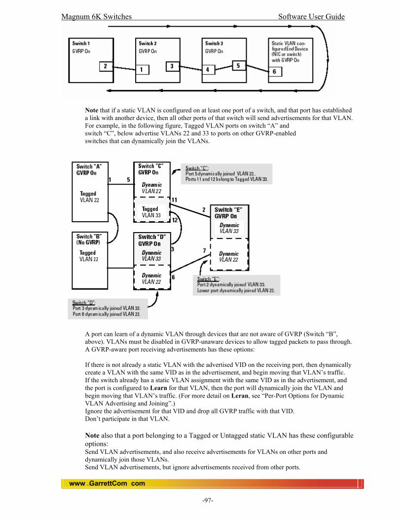
Magnum 6K Switches Software User Guide
www GarrettCom com..
-97-
Note that if a static VLAN is configured on at least one port of a switch, and that port has established a link with another device, then all other ports of that switch will send advertisements for that VLAN. For example, in the following figure, Tagged VLAN ports on switch “A” and switch “C”, below advertise VLANs 22 and 33 to ports on other GVRP-enabled switches that can dynamically join the VLANs.
A port can learn of a dynamic VLAN through devices that are not aware of GVRP (Switch “B”, above). VLANs must be disabled in GVRP-unaware devices to allow tagged packets to pass through. A GVRP-aware port receiving advertisements has these options: If there is not already a static VLAN with the advertised VID on the receiving port, then dynamically create a VLAN with the same VID as in the advertisement, and begin moving that VLAN’s traffic. If the switch already has a static VLAN assignment with the same VID as in the advertisement, and the port is configured to Learn for that VLAN, then the port will dynamically join the VLAN and begin moving that VLAN’s traffic. (For more detail on Leran, see “Per-Port Options for Dynamic VLAN Advertising and Joining”.) Ignore the advertisement for that VID and drop all GVRP traffic with that VID. Don’t participate in that VLAN. Note also that a port belonging to a Tagged or Untagged static VLAN has these configurable options: Send VLAN advertisements, and also receive advertisements for VLANs on other ports and dynamically join those VLANs. Send VLAN advertisements, but ignore advertisements received from other ports.

Magnum 6K Switches Software User Guide
www GarrettCom com..
-98-
Avoid GVRP participation by not sending advertisements and dropping any advertisements received from other devices.
17.3 Per-Port Options for Handling GVRP “Unknown VLANs” An “unknown VLAN” is a VLAN that the switch learns of by GVRP. For example, suppose that port 1 on switch “A” is connected to port 5 on switch “C”. Because switch “A” has VLAN 22 statically configured, while switch “C” does not have this VLAN statically configured, VLAN 22 is handled as an “Unknown VLAN” on port 5 in switch “C”. Conversely, if VLAN 22 was statically configured on switch C, but port 5 was not a member, port 5 would become a member when advertisements for VLAN 22 were received from switch “A”. When you enable GVRP on a switch, you have the per-port join-request options
The CLI show-vlan (command line interface VLAN Support screen) shows a switch’s current GVRP configuration, including the Unknown VLAN settings.
Magnum6K25(GVRP)## show-vlan
17.4 Per-Port Options for Dynamic VLAN Advertising and Joining
Initiating Advertisements. As described in the preceding section, to enable dynamic joins, GVRP must be enabled and a port must be configured to Learn (the default). However, to send advertisements in your network, one or more Tagged or Untagged static VLANs must be configured on one or more switches (with GVRP enabled), depending on your topology.
17.4.1 Enabling a Static VLAN for Dynamic Joins.
You can configure a port to dynamically join a static VLAN (that shares the same VID) if that port subsequently receives an advertisement for the static VLAN. (This is done by using the Learn option described in table, below.
17.4.2 Parameters for Controlling VLAN Propagation Behavior.
On an individual port, you can configure an existing static VLAN to actively or passively participate in dynamic VLAN propagation or to ignore dynamic VLAN (GVRP) operation. These options are controlled by the GVRP “Unknown VLAN” and the static VLAN configuration parameters, as described in the following table:

Magnum 6K Switches Software User Guide
www GarrettCom com..
-99-
As the above table indicates, when you enable GVRP, a port that has a Tagged or Untagged static VLAN has the option for both generating advertisements and dynamically joining other VLANs. Note In table , above, the Unknown VLAN parameters are configured on a per interface basis using the CLI. The Tagged, Untagged, Auto, and Forbid options are configured in the VLAN context using either the menu interface or the CLI. Because dynamic VLANs operate as Tagged VLANs, and because a tagged port on one device cannot communicate with an untagged port on another device, GarrettCom recommends that you use Tagged VLANs for the static VLANs you will use to generate advertisements.
17.5 GVRP and VLAN Access Control
When you enable GVRP on a switch, the default GVRP parameter settings allow all of the switch’s ports to transmit and receive dynamic VLAN advertisements (GVRP advertisements) and to dynamically join VLANs. The two preceding sections describe the per-port features you can use to control and limit VLAN propagation. To summarize, you can: Allow a port to advertise and/or join dynamic VLANs (the default). Allow a port to send VLAN advertisements, but not receive them from other devices; that is, the port cannot dynamically join a VLAN but other devices can dynamically join the VLANs it advertises. Prevent a port from sending dynamic VLAN advertisements for specific VLANs Prevent a port from participating in GVRP operation.
17.6 Port-Leave From a Dynamic VLAN
A dynamic VLAN continues to exist on a port for as long as the port continues to receive advertisements of that VLAN from another device connected to that port or until you: Convert the VLAN to a static VLAN (See “Converting a Dynamic VLAN to a Static VLAN”.) -Reconfigure the port to Block or Disable -Disable GVRP -Reboot the switch The time-to-live for dynamic VLANs is 10 seconds. That is, if a port has not received an advertisement for an existing dynamic VLAN during the last 10 seconds, the port removes itself from that dynamic VLAN. Converting a Dynamic VLAN to a Static VLAN. If GVRP is running on the switch and a port dynamically joins a VLAN, you can use the next command to convert the dynamic VLAN to a static VLAN. This is necessary if you want to make the VLAN permanent. Note: After you convert a dynamic VLAN to static, you must configure the switch’s per-port participation in the VLAN in the same way that you would for any static VLAN. Syntax: static vlan=<dynamic vlanid>

Magnum 6K Switches Software User Guide
www GarrettCom com..
-100-
If you need a VID reference, use show vlan type=tag to list the switch’s currently existing VLANs. For example, suppose a dynamic VLAN with a VID of 10 exists on the switch. The following command converts the VLAN to a static VLAN. Magnum6K25(gvrp)# static vlan=10 Once dynamic Vlan converted into static, it needs to configure as a normal static Vlan. Magnum6K25(gvrp)# show-vlan
17.7 Planning for GVRP Operation
These steps outline the procedure for setting up dynamic VLANs for a segment. 1. Determine the VLAN topology you want for each segment (broadcast domain) on your network. 2. Determine the VLANs that must be static and the VLANs that can be dynamically propagated. 3. Determine the device or devices on which you must manually create static VLANs in order to propagate VLANs throughout the segment. 4. Determine security boundaries and how the individual ports in the segment will handle dynamic VLAN advertisements. (See tables above.) 5. Enable GVRP on all devices you want to use with dynamic VLANs and configure the appropriate “Unknown VLAN” parameter (Learn, Block, or Disable) for each port. 6. Configure the static VLANs on the switch(es) where they are needed, along with the per-VLAN parameters (Tagged, Untagged, and Forbid—see table on the appropriate ports. 7. Dynamic VLANs will then appear automatically, according to the configuration options you have chosen. 8. Convert dynamic VLANs to static VLANs where you want dynamic VLANs to become permanent.
17.8 Configuring GVRP On a Switch The procedures in this section describe how to: View the GVRP configuration on a switch Enable and disable GVRP on a switch Specify how individual ports will handle advertisements To view or configure static VLANs for GVRP operation, refer to “Port-Based Virtual LANs (Static VLANs)” CLI: Viewing and Configuring GVRP Displaying the Switch’s Current GVRP Configuration. This command shows whether GVRP is disabled, along with the current settings for the maximum number of VLANs and the current Primary VLAN. (For more on the last two parameters, see “Port-Based Virtual LANs (Static VLANs)” ) Syntax: show gvrp Magnum6K25#show gvrp GVRP Status : Enabled
17.9 Enabling and Disabling GVRP on the Switch.
This command enables GVRP on the switch. Syntax: gvrp <enable/disable> Magnum6K25(gvrp)##gvrp enable GVRP enabled Magnum6K25(gvrp)##gvrp disable
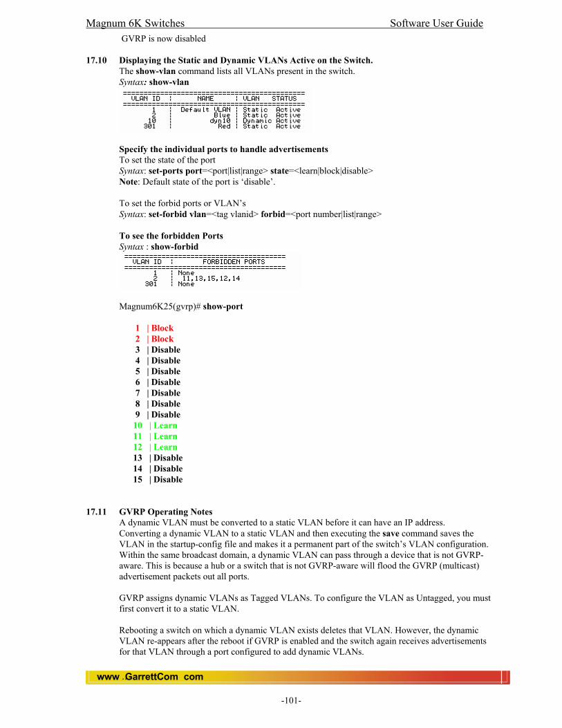
Magnum 6K Switches Software User Guide
www GarrettCom com..
-101-
GVRP is now disabled 17.10 Displaying the Static and Dynamic VLANs Active on the Switch.
The show-vlan command lists all VLANs present in the switch. Syntax: show-vlan
Specify the individual ports to handle advertisements To set the state of the port Syntax: set-ports port=<port|list|range> state=<learn|block|disable> Note: Default state of the port is ‘disable’. To set the forbid ports or VLAN’s Syntax: set-forbid vlan=<tag vlanid> forbid=<port number|list|range> To see the forbidden Ports Syntax : show-forbid
Magnum6K25(gvrp)# show-port 1 | Block 2 | Block 3 | Disable 4 | Disable 5 | Disable 6 | Disable 7 | Disable 8 | Disable 9 | Disable 10 | Learn 11 | Learn 12 | Learn 13 | Disable 14 | Disable 15 | Disable
17.11 GVRP Operating Notes
A dynamic VLAN must be converted to a static VLAN before it can have an IP address. Converting a dynamic VLAN to a static VLAN and then executing the save command saves the VLAN in the startup-config file and makes it a permanent part of the switch’s VLAN configuration. Within the same broadcast domain, a dynamic VLAN can pass through a device that is not GVRP-aware. This is because a hub or a switch that is not GVRP-aware will flood the GVRP (multicast) advertisement packets out all ports. GVRP assigns dynamic VLANs as Tagged VLANs. To configure the VLAN as Untagged, you must first convert it to a static VLAN. Rebooting a switch on which a dynamic VLAN exists deletes that VLAN. However, the dynamic VLAN re-appears after the reboot if GVRP is enabled and the switch again receives advertisements for that VLAN through a port configured to add dynamic VLANs.
Magnum 6K Switches Software User Guide
www GarrettCom com..
-102-
By receiving advertisements from other devices running GVRP, the switch learns of static VLANs on those other devices and dynamically (automatically) creates tagged VLANs on the links to the advertising devices. Similarly, the switch advertises its static VLANs to other GVRP-aware devices. A GVRP-enabled switch does not advertise any GVRP-learned VLANs out of the port(s) on which it originally learned of those VLANs.
17.12 Web: View and Configure GVRP Parameters
In the web browser interface: 1. Click on the [Configuration]. 2. Click on [Vlan]. 3. Click on [GVRP]. 4. Click on toggle button to enable or disable GVRP. 5. After you make the desired changes, click on [OK] button. 6. Click [Save] to save the configuration.
Through this menu you can also change the Port State to ‘block’ or ‘learn’ of a specific port.
For web-based Help on how to use the web browser interface screen, click on the [Help] button provided on the web browser screen.

Magnum 6K Switches Software User Guide
www GarrettCom com..
-103-
18.0 S-Ring 18.1 Introduction
S-Ring™ feature enables Magnum 6K Managed Switches to simplify and speed up recovery from faults in Ethernet LAN configurations that use a ring structure. It is built upon networking software standards such as IEEE 802.1d Spanning Tree Protocol (STP). The user configures and controls S-Ring as part of the 6K Switch’s management software. The S-Ring feature can be used in multi-vendor LANs running standard STP on the Magnum 6Ks along with other switches and hubs in any redundant LAN topology, including rings and meshes. S-Ring makes Ethernet ring-topology more reliable and faster without sacrificing the benefit of standards-based interoperability.
The S-Ring feature operates from specifically defined port pairs that have ring-topology Ethernet devices attached. Multiple rings of different pairs on the same switch are also supported. It builds upon the foundation of STP, but offers an additional option related specifically to ring topologies. Each of the two ends of a ring must be connected to two ports in a Magnum 6K Switch that is running the S-Ring software. To understand the S-Ring feature, first examine the fault recovery of an Ethernet LAN ring configuration with only standard STP (no S-Ring) in operation. Note: Refer STP chapter of MNS-6K to understand the STP operation.
The S-Ring feature is a separately licensed module for the MNS-6K software package. This module must be enabled by means of a software key.
The S-Ring feature provides rapid recovery of a ring topology network of switches. It is based on the Spanning Tree Protocol, and works in conjunction with it. A number of switches can be connected in a ring topology, where STP will keep the ring open. When a fault occurs at any location on the link, STP will close the ring, resulting in re establishment of an alternate path if a redundant ring was originally created.
18.2 How to Activate S-Ring Module
If it is not already activated at the factory, or if you have cleared the configuration FLASH memory, you have to activate the S-Ring module. You need the 12 character security key to activate it.
To activate the S-Ring module, type the following CLI command Syntax: authorize <module> key=<security key> Replace <security key> with the actual 12 character key string. (Note: For Security Key, please contact sales or support.)
E.g., Magnum6K25# authorize s-ring key=abc123456789 Save the configuration to make it permanent.
18.3 S-Ring user interface
The S-ring commands are available within the “STP” module. Note: STP must be enabled for s-ring to work. (Refer STP chapter for STP configuration.)
The commands themselves are available even if STP is disabled, but the s-ring action will not take place without STP.
18.4 How to configure S-Ring
First of all, ensure that STP is enabled. Otherwise, enable STP functionality. To start this, go to the STP context and type STP enable and press <enter>. Magnum6K25# stp <enter> Magnum6K25(stp)##

Magnum 6K Switches Software User Guide
www GarrettCom com..
-104-
Magnum6K25(stp)## stp enable If the security key code is already entered the S-Ring module should be enabled. This can be verified by using the “show s-ring” command. If the module is not enabled, S-Ring status shows DISABLED. Magnum6K25(stp)## show s-ring sRing Status: DISABLED
To enable S-Ring, Magnum6K25(stp)## s-ring enable sRing Enabled. There are two options to configure S-ring.
You can pre-configure a pair of ports, and then connect the ring to them, or Connect the ring first and then use the learn feature to add the ports to the database.
Note: The latter would be simpler in most cases. The learn feature can be used with rings which are already in place, fully connected. A ring is fully connected when it consists of a string (one or many) of switches/hubs, none of which are running STP, so that when the two ends of the string are hooked onto a pair of ports on the 6K switch, the ring completes.
If you already have the ring fully connected and hooked up onto 6K switch, then type Syntax: s-ring learn and press <enter>. Magnum6K25(stp)## s-ring learn SRING Learn Initiated. Scan Time: 20 Seconds The system will display the scan time (which is twice the forward delay timer value of the STP module, typically 20 seconds). The scanning happens in background and does not interrupt data on already communicating ports.
You can use the show s-ring command to see if the ring you have connected has been learned. If your ring does not show up, it means it is not fully connected. That is, either the data path is broken somewhere, or another switch with STP is connected to the ring.
Alternatively, you can type Syntax:s-ring add port=<port1>,<port2> to add the port pair. Note: The port numbers are separated by a coma, and no spaces. Magnum6K25(stp)##s-ring add port=1,7 Ports 1 and 7 Configured for sRing Operation
Use show s-ring command to check if the ports are added properly. If the ring is attached to the ports and is fully connected, the ring status will show “CLOSED”. If the ring has never been activated by BPDUs will show “INITIAL” and if the ring is attached, but unknown BPDUs occur it will show “NO RING”
Magnum6K25#show s-ring Magnum Ring Status: sRing Status: ENABLED Port 1 Port 2 Status 1 7 CLOSED
Once the ring is established and s-ring gets
RingClose
Blocking Forwarding

Magnum 6K Switches Software User Guide
www GarrettCom com..
-105-
the port pair into its database, it will start monitoring the ports for continued flow of STP BPDUs and also for the Link-Loss-Learn signal used by the mP62 switches. If the BPDU stream is broken, or it finds the Link-Loss-Learn signal, the system will immediately force STP to put both ports in forwarding mode. The ring status will now be “OPEN”. Note: To learn more about “Link-Loss-Learn”, see section and please visit our web site www.garrettcom.com.
Preventive Measures If the ring sees BPDUs not belonging to itself on any of the ports, it will set the ring to “UNKNOWN” state, and stop all ring activity on that ring. The ring activity has several timers and safeguards to prevent erroneous operation. Ring faults are not expected to happen in quick succession. Hence, if the ring system sees a sequence of changes in the duration of a less than a second each, it will temporarily ignore the signals and leave STP to re configure the ring using the normal algorithms.
18.4.1 CLI Commands
show s-ring s-ring
The show s-ring command will display the current configuration and status of s-ring operation. Magnum6K25#show s-ring Magnum Ring Status: sRing Status: ENABLED Port 1 Port 2 Status 1 7 CLOSED
The s-ring command has several options and arguments. S-ring is a part of the STP module. To configure the S-ring, you have to go to the STP configuration mode first. Magnum6K25# stp <enter> Magnum6K25(stp)##
Syntax: s-ring learn E.g., Magnum6K25(stp)## s-ring learn
Learn command will initiate scanning of all ports for presence of rings. Any ring found will be added to the database and will be monitored for breaks. Any rings already configured, but not present at the time of learning will be deleted.
Syntax: s-ring add port=<port1>,<port2> E.g., Magnum6K25(stp)## s-ring add port=1,7
This command specifies a pair of ports, consisting of port1 and port2 participating in s-ring operation. It will add the ports into the ring database, and start monitoring for the physical presence of the ring.
Ring Open
Changed to Fwding

Magnum 6K Switches Software User Guide
www GarrettCom com..
-106-
This is done by monitoring the STP BPDUs (Bridge Protocol Data Unit) on both of the ring ports. When a BPDU transmitted by one of the ring ports is received on the other ring port, the ring is marked as “CLOSED”. The system will continue to monitor the ports for BPDUs. When a BPDU is missing, the system decides that the ring has faulted, and forces STP to close the path immediately.
Syntax: s-ring del port=<port1>,<port2> E.g., Magnum6K25(stp)## s-ring del port=1,7 This command will delete the port pair from the s-ring operation.
Syntax: s-ring enable/disable E.g., Magnum6K25(stp)## s-ring enable This command globally enables or disables s-ring operation. If disabled, the s-ring module does not affect any function of the switch.
18.5 Web: View and Configure S-Ring In the web browser interface: 1. Click on the [Configuration]. 2. Click on [STP/RSTP]. 3. Click on [S-Ring]. 4. Click on [Add] to add Ring Ports. 5. After you make the desired changes, click on [OK] button. 7. Click [Save] to save the configuration.
18.6 Link-Loss Learn Feature
The Link-Loss Learn is a unique feature of the Magnum 6K switches. When the link is lost on any port on which this function is enabled, the address table is reset and the address learning process is re-initiated. This will allow rapid recovery of traffic.
The Link-Loss-Learn feature of the Magnum 6K Ethernet Switch addresses issues that can occur when 6Ks are used in redundant network configurations, such as when Spanning Tree Protocol (STP) is in use. With Link-Loss-Learn, Magnum 6K’s are better able to handle some fault recovery situations and they may improve network reliability and provide faster fault recovery accordingly. Without a redundant network topology, the Link-Loss-Learn feature has no significant benefit and should be turned off via the applicable MNS-6K software CLI command. The factory default setting is “off/disabled”. For more information on Link-Loss feature, please visit www.garrettcom.com.
The ports on which this capability is to be enabled are entered through a CLI command.
18.6.1 CLI
Link-Loss-Learn (LLL) commands are available under STP context. Magnum6K25# stp <enter> Magnum6K25(stp)##
To enable/disable Syntax: lll <enable/disable> Magnum6K16(stp)##lll enable Link-Loss-Learn Enabled.
Note: If STP is enabled, Link Loss Learn will not work even though if you enable it.
Magnum6K16(stp)##lll disable Link-Loss-Learn Disabled.
Magnum 6K Switches Software User Guide
www GarrettCom com..
-107-
To add LLL Ports Syntax: lll add port=<port|list|range> Magnum6K16(stp)##lll add port=1,2,3 Added Ports: 1,2,3 To delete LLL Ports Syntax: lll del port=<port|list|range> Magnum6K16(stp)##lll del port=2,3 Deleted Ports: 2,3
To see the status Syntax: show lll Magnum6K16(stp)##show lll Link-Loss-Learn Status: LLL Status: ENABLED LLL Enabled on Ports: 1,2,3
18.7 Web: View and Configure Link Loss Learn In the web browser interface: 1. Click on the [Configuration]. 2. Click on [STP/RSTP]. 3. Click on [Link Loss Learn]. 4. Click on [EDIT] to add or delete Ports. 5. After you make the desired changes, click on [OK] button. 6. Click [Save] to save the configuration.

Magnum 6K Switches Software User Guide
www GarrettCom com..
-108-
19.0 Alarm Relay System
The Magnum 6K switches have a software (optional) controlled relay contact that can be use to report alarm conditions. The relay is held open in normal circumstances and will go to close position during alarm conditions. Two types of alarm signals are defined in the alarm system.
• SUSTAINED • MOMENTARY
The SUSTAINED mode is used to report a continuing error condition. The MOMENTARY mode is used to report a single event.
The following pre-defined events are currently supported on the alarm system.
Event ID Event Description Signal Type 1 S-RING OPEN SUSTAINED 2 Cold Start MOMENTARY 3 Warm Start MOMENTARY 4 Link Up MOMENTARY 5 Link Down MOMENTARY 6 Authentication Failure MOMENTARY 7 RMON Raising Alarm MOMENTARY 8 RMON Falling Alarm MOMENTARY 9 Intruder Alarm MOMENTARY 10 Link Loss Learn Triggered MOMENTARY 11 Broadcast Storm Detected MOMENTARY 12 STP/RSTP Reconfigured MOMENTARY
(Note: For System event Log, please read the chapter 20, section 20.6)
The S-RING open condition generates a sustained relay contact close. The relay will stay closed during the period which the S-RING is in OPEN condition. The relay will revert to closed position when the S-RING goes to CLOSED position (For S-Ring details, please read S-Ring Chapter). The Intruder Alarm is nothing but the Port Security event.
The relay will close for a configurable (1 to 10 seconds) time interval when the other events occur.
19.1 CLI
Alarms can be configured under Alarm module. Magnum6K25# alarm <enter> Magnum6K25(alarm)## add event: This command enables alarm action in response to the specified event ID. Syntax: add event=<event Id> Magnum6K25(alarm)## add event=2 Alarm Event Added Successfully User can add multiple Alarm events together. Magnum6K25(alarm)## add event=1,2,6,9 Alarm Event(s) Added: 1, 2, 3
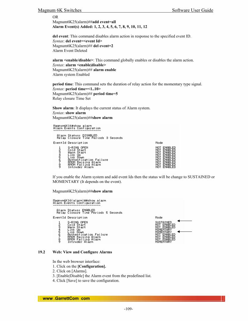
Magnum 6K Switches Software User Guide
www GarrettCom com..
-109-
OR Magnum6K25(alarm)##add event=all Alarm Event(s) Added: 1, 2, 3, 4, 5, 6, 7, 8, 9, 10, 11, 12
del event: This command disables alarm action in response to the specified event ID. Syntax: del event=<event Id> Magnum6K25(alarm)## del event=2 Alarm Event Deleted
alarm <enable/disable>: This command globally enables or disables the alarm action. Syntax: alarm <enable|disable> Magnum6K25(alarm)## alarm enable Alarm system Enabled
period time: This command sets the duration of relay action for the momentary type signal. Syntax: period time=<1..10> Magnum6K25(alarm)## period time=5 Relay closure Time Set
Show alarm: It displays the current status of Alarm system. Syntax: show alarm Magnum6K25(alarm)##show alarm
If you enable the Alarm system and add event Ids then the status will be change to SUSTAINED or MOMENTARY (It depends on the event).
Magnum6K25(alarm)##show alarm
19.2 Web: View and Configure Alarms
In the web browser interface: 1. Click on the [Configuration]. 2. Click on [Alarms]. 3. [Enable|Disable] the Alarm event from the predefined list. 4. Click [Save] to save the configuration.

Magnum 6K Switches Software User Guide
www GarrettCom com..
-110-
20.0 SMTP (Simple Mail Transfer Protocol)
SMTP (RFC 821) is a TCP/IP protocol used in sending e-mail. However, since it’s limited in its ability to queue messages at the receiving end, it’s usually used with one of two other protocols, POP3 or Internet Message Access Protocol that let the user save messages in a server mailbox and download them periodically from the server. In other words, users typically use a program that uses SMTP for sending e-mail and either POP3 or IMAP for receiving messages that have been received for them at their local server. SMTP is implemented to operate over Transmission Control Protocol (TCP) port 25. The details of SMTP are in Request for Comments 821 of the Internet Engineering Task Force (IETF). In Magnum 6K switches, SMTP is used to send email alerts whenever there is an event or an SNMP trap generated inside the switch system.
• Send email alert according to the configuration rules when a specific event category happens
• Send email alert according to the configuration rules when a specific trap SNMP trap category happens
• Provide configuration and customization commands for users to specify SMTP server to connect to, TCP ports, user recipients and filters.
20.1 Email Alert Features
• The following features are implemented in 6K SMTP Alert Module:
• SMTP alerts can be enabled or disabled globally.
• User can defined a global default SMTP server identified by its IP address, TCP port and retry count.
• User can add up to five SMTP alert recipients. Each recipient is identified by an ID and email address.
• Filters are provided for each recipient to allow only certain categories of traps and events be sent by email.
• Each recipient can have its own SMTP server and TCP port number, if this is not defined on a certain recipient, the default SMTP server and TCP port number is used.
20.2 CLI
Trap and Event email alerts can be enabled through SMTP module. Magnum6K25#smtp Magnum6K25(smtp)## Syntax: show smtp <config|recipients> config – when this option is chosen, it shows the current SMTP global settings. recipients – choosing this option shows the currently configured recipients of email alerts.

Magnum 6K Switches Software User Guide
www GarrettCom com..
-111-
Magnum6K25(smtp)##show smtp config
Magnum6K25(smtp)##show smtp recipients
Syntax: add id=<1-5> email=<email-addr> [traps=<all|none|S|R|E>] [events=<all|none|I|A|C|F|D>] [ip=<ip-addr>] [port=<1-65535>] id – [mandatory] the recipient ID range from 1 to 5. Five is the maximum number of recipients. email – [mandatory] this is the email address of the recipient traps – [optional] this is the trap filter. If value is “all”, all traps of any type will be sent to this recipient. If value is none, no traps are sent to this recipient. Value can also be a combination of ‘S’ (SNMP), ‘R’ (RMON) and ‘E’ (ENTERPRISE). For example, trap=SR means that SNMP and RMON types will be sent to recipient. If this option is not defined, the recipient will have a default value of “all”. events – [optional] this is the event filter. Value can be “all” (all event severity types will be sent to recipient), “none” (no event will be sent to recipient), or a combination of ‘I’ (informational), ‘A’ (activity), ‘C’ (critical), ‘F’ (fatal) and ‘D’ (debug). event=ACF means that events of severity types activity, critical and fatal will be sent to recipients by email. If this option is not defined, a value of “all” is taken. ip – [optional] SMTP server IP address. This is the SMTP server to connect to for this particular user. If this option is not defined, the global/default SMTP server is used. port – [optional] TCP port of the SMTP server. If this is not defined, the global default TCP port is used. Magnum6K25(smtp)##add id=2 [email protected] traps=all events=all Recipient successfully added Syntax: delete id=<1-5> id – [mandatory] the recipient ID range from 1 to 5. 5 is the maximum number of recipients. Magnum6K25(smtp)##delete id=2 Recipient successfully deleted Syntax: sendmail server=<ip-addr> to=<email-addr> from=<email-addr> subject=<string> body=<string> This command allows the user to send a customize email. server – [mandatory] SMTP server address. to – [mandatory] the recipient email address. from – [mandatory] the sender email address.

Magnum 6K Switches Software User Guide
www GarrettCom com..
-112-
subject – [mandatory] email subject or title. body – [mandatory] email body. Magnum6K25(smtp)##sendmail server=10.21.1.2 [email protected] [email protected] subject=test body=hello Syntax: server ip=<ip-addr> [port=<1-65535>] [retry=<0-3>] This command configures the global default SMTP server. ip – [mandatory] SMTP server IP address. port – [mandatory] TCP port. retry – [optional] specifies how many times to retry if an error occurs when sending email. Range from 0 to 3. Default is 0. Magnum6K25(smtp)##server ip=10.21.1.2 port=25 retry=2 Successfully set global SMTP server configuration Syntax: smtp <enable|disable> This enables or disables SMTP alert. enable/disable – [mandatory] Enables or disables SMTP alert. Here is an example of email alert: THIS IS A GENERATED E-MAIL ALERT COMING FROM AN M6K SWITCH! PLEASE DO NOT REPLY! An event was detected on Magnum 6K switch 192.168.1.150, the event description shown below: Event Code : 80 Source : CLI Date & Time : Monday 01-01-2004 (in mm-dd-yyyy format) 12:29:13 A.M Description: manager console login Severity: INFORMATIONAL Note: Email alerts can be forward to email station or cell phone (email/text capable).
20.3 Web: View and Configure SMTP Relay In the web browser interface: 1. Click on the [Configuration]. 2. Click on [SMTP]. 3. Click on [EDIT] (Top Screen) to add or edit SMTP Server information. 4. Click on [ADD] (Bottom Screen) to add or edit the Email client and Trap information. 5. After you make the desired changes, click on [OK] button. 6. Click [Save] to save the configuration.

Magnum 6K Switches Software User Guide
www GarrettCom com..
-113-
21.0 802.1x - Port Based Network Access Control and The Radius (Remote Authentication Dial-In User Service) Protocol
21.1 Introduction The IEEE 802.1x standard, Port Based Network Access Control, defines a mechanism for port-based network access control that makes use of the physical access characteristics of IEEE 802 LAN infrastructure. It provides a means of authenticating and authorizing devices attached to LAN ports that have point-to-point connection characteristics. It also prevents access to that port in cases where the authentication and authorization fails. The 802.1x specification includes a number of features aimed specifically at supporting the use of Port Access Control in IEEE 802.11 LANs (WLAN). These include the ability for a WLAN access point to distribute or obtain global key information to/from attached stations by means of the EAPOL-Key message following successful authentication. Although 802.1x is mostly used in wireless networks, this protocol is also implemented in wired bridges. The Magnum MNS-6K Software switch implements the authenticator, which is a major component of 802.1x.
21.2 Overview 802.1x is a method for performing authentication to obtain access to IEEE 802 LANs. It specifies the following:
• the protocol between devices desiring access to the bridged LAN and devices providing access to the bridged LAN
• the requirements for a protocol between the authenticator and an authentication server (RADIUS)
• the behavior of the port providing access to the bridged LAN
• management operations via SNMP
Figure 1 shows a general topology of 802.1x enabled network.
Figure 1. 802.1x General Topology
There are 3 major components of 802.1x: Supplicant, Authenticator and Authentication Server. In Figure 1, the PC acts as the supplicant. The supplicant is an entity being authenticated and desiring access to the services of the authenticator. The switch in Figure 1 is the authenticator. The authenticator enforces authentication before allowing access to services that are accessible via that port. The authenticator is responsible for communication with the supplicant and for submitting the information received from the supplicant to a suitable authentication server. This allows the verification of user credentials to determine the consequent port authorization state. It is important to note that the authenticator’s functionality is independent of the actual authentication method. It effectively acts as a pass-through for the authentication exchange. The RADIUS server in Figure 1 is the authentication server. The authentication server provides a

Magnum 6K Switches Software User Guide
www GarrettCom com..
-114-
standard way of providing Authentication, Authorization, and Accounting services to a network.
21.3 Protocol Operation Communication between a supplicant and authenticator is via EAPOL (EAP over LAN). Authenticator and authentication server communicate using EAP over RADIUS. The ff. illustrations show the protocol involved between 802.1x entities.
Figure 2. 802.1x Protocol
EAP, short for Extensible Authentication Protocol, is an authentication framework which supports multiple authentication methods. EAP typically runs directly over data link layers such as PPP or IEEE 802, without requiring IP. EAP over LAN or EAPOL encapsulates EAP packets onto 802 frames with a few extensions to handle 802 characteristics. EAP over RADIUS encapsulates EAP packets onto RADIUS packets for relaying to RADIUS authentication servers. Figure 3 below shows the protocol conversation and flow between a supplicant, an authenticator and an authentication server.
Figure 3. Protocol Conversation
The illustration above is described on the following steps:
1. The supplicant (laptop/host) is initially blocked from accessing network services. For example, the laptop user can access the switch management services as well as access other
Magnum 6K Switches Software User Guide
www GarrettCom com..
-115-
hosts and their services in the network. The supplicant wanting to access these services starts with an EAPOL-Start frame.
2. The authenticator (Bridge/switch), upon receiving an EAPOL-start frame, sends a response with an EAP-Request/Identity frame back to the supplicant. This will inform the supplicant to give its identity.
3. The supplicant will then send back its own ID using an EAP-Response/Identity frame to the authenticator. The authenticator will then relay this to the authentication server by encapsulating the EAP frame on a RADIUS-Access-Request packet.
4. The RADIUS server will then send the authenticator a RADIUS-Access-Challenge packet. The authenticator will relay this to challenge the supplicant using an EAP-Request frame. This will inform the supplicant to pass all its credentials for authentication.
5. The supplicant will then send its credentials using an EAP-Response frame with which the authenticator will relay using a RADIUS-Access-Request packet.
6. If the supplicant’s credentials are valid, a RADIUS-Access-Accept is sent to the authenticator. The authenticator will then relay this on as an EAP-Success.
7. If the supplicant does not have the necessary credentials, a RADIUS-Access-Deny packet is sent back and relayed to the supplicant as an EAP-Failure frame.
The Magnum MNS-6K Software implements the 802.1x authenticator. It fully conforms to the standards as described in IEEE 802.1x, implementing all the state machines needed for port-based authentication. The Magnum MNS-6K Software authenticator supports both EAPOL and EAP over RADIUS to communicate to a standard 802.1x supplicant and RADIUS authentication server. The Magnum MNS-6K Software authenticator has the following characteristics:
• Allow control on ports using STP-based hardware functions. EAPOL frames are STP-link Bridge PDUs (BPDU) with its own bridge multicast address.
• Relays MD5 challenge (although not limited to) authentication protocol to RADIUS server
• Support 1 host per port authentication (limited to specification and hardware constraints)
• It supports the following management functions:
o IEEE 802.1x MIB for SNMP management
o Command Line Interface
o Web-management 21.4 CLI
CLI Commands to configure and perform 802.1x security feature. Auth: This command will take you to the command context of “auth” context,
Syntax: auth <enter> Magnum6K25#auth
Magnum6K25(auth)##
show auth: This command shows the current general authenticator global and port configuration.
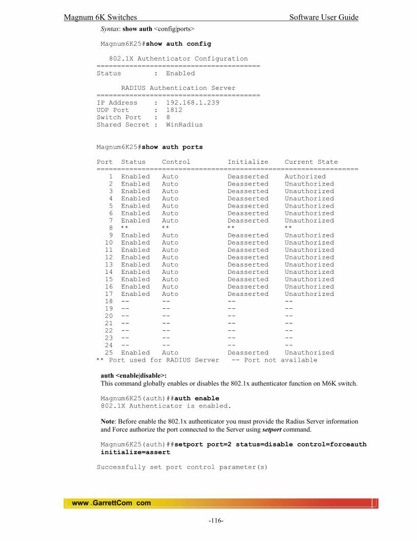
Magnum 6K Switches Software User Guide
www GarrettCom com..
-116-
Syntax: show auth <config|ports>
Magnum6K25#show auth config 802.1X Authenticator Configuration ======================================== Status : Enabled RADIUS Authentication Server ======================================== IP Address : 192.168.1.239 UDP Port : 1812 Switch Port : 8 Shared Secret : WinRadius Magnum6K25#show auth ports Port Status Control Initialize Current State ================================================================ 1 Enabled Auto Deasserted Authorized 2 Enabled Auto Deasserted Unauthorized 3 Enabled Auto Deasserted Unauthorized 4 Enabled Auto Deasserted Unauthorized 5 Enabled Auto Deasserted Unauthorized 6 Enabled Auto Deasserted Unauthorized 7 Enabled Auto Deasserted Unauthorized 8 ** ** ** ** 9 Enabled Auto Deasserted Unauthorized 10 Enabled Auto Deasserted Unauthorized 11 Enabled Auto Deasserted Unauthorized 12 Enabled Auto Deasserted Unauthorized 13 Enabled Auto Deasserted Unauthorized 14 Enabled Auto Deasserted Unauthorized 15 Enabled Auto Deasserted Unauthorized 16 Enabled Auto Deasserted Unauthorized 17 Enabled Auto Deasserted Unauthorized 18 -- -- -- -- 19 -- -- -- -- 20 -- -- -- -- 21 -- -- -- -- 22 -- -- -- -- 23 -- -- -- -- 24 -- -- -- -- 25 Enabled Auto Deasserted Unauthorized ** Port used for RADIUS Server -- Port not available
auth <enable|disable>: This command globally enables or disables the 802.1x authenticator function on M6K switch. Magnum6K25(auth)##auth enable 802.1X Authenticator is enabled. Note: Before enable the 802.1x authenticator you must provide the Radius Server information and Force authorize the port connected to the Server using setport command. Magnum6K25(auth)##setport port=2 status=disable control=forceauth initialize=assert
Successfully set port control parameter(s)
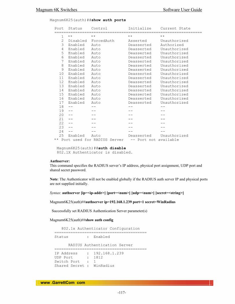
Magnum 6K Switches Software User Guide
www GarrettCom com..
-117-
Magnum6K25(auth)##show auth ports Port Status Control Initialize Current State ================================================================ 1 ** ** ** ** 2 Disabled ForcedAuth Asserted Unauthorized 3 Enabled Auto Deasserted Authorized 4 Enabled Auto Deasserted Unauthorized 5 Enabled Auto Deasserted Unauthorized 6 Enabled Auto Deasserted Unauthorized 7 Enabled Auto Deasserted Unauthorized 8 Enabled Auto Deasserted Unauthorized 9 Enabled Auto Deasserted Unauthorized 10 Enabled Auto Deasserted Unauthorized 11 Enabled Auto Deasserted Unauthorized 12 Enabled Auto Deasserted Unauthorized 13 Enabled Auto Deasserted Unauthorized 14 Enabled Auto Deasserted Unauthorized 15 Enabled Auto Deasserted Unauthorized 16 Enabled Auto Deasserted Unauthorized 17 Enabled Auto Deasserted Unauthorized 18 -- -- -- -- 19 -- -- -- -- 20 -- -- -- -- 21 -- -- -- -- 22 -- -- -- -- 23 -- -- -- -- 24 -- -- -- -- 25 Enabled Auto Deasserted Unauthorized ** Port used for RADIUS Server -- Port not available
Magnum6K25(auth)##auth disable 802.1X Authenticator is disabled.
Authserver: This command specifies the RADIUS server’s IP address, physical port assignment, UDP port and shared secret password.
Note: The Authenticator will not be enabled globally if the RADIUS auth server IP and physical ports are not supplied initially.
Syntax: authserver [ip=<ip-addr>] [port=<num>] [udp=<num>] [secret=<string>] Magnum6K25(auth)##authserver ip=192.168.1.239 port=1 secret=WinRadius Successfully set RADIUS Authentication Server parameter(s) Magnum6K25(auth)##show auth config 802.1x Authenticator Configuration ======================================== Status : Enabled RADIUS Authentication Server ======================================== IP Address : 192.168.1.239 UDP Port : 1812 Switch Port : 1 Shared Secret : WinRadius

Magnum 6K Switches Software User Guide
www GarrettCom com..
-118-
Backend: This command configures parameters needed by the authenticator when communicating the authentication protocol with the backend RADIUS authentication server.
Syntax: backend port=<num|list|range> supptimeout=<1-240>] [servertimeout=<1-240>] [maxreq=<1-10>] port – [mandatory] – ports to be configured supptimeout – [optional] This is the timeout in seconds the authenticator waits for the supplicant to respond back. Default value is 30 seconds. Values can range from 1 to 240 seconds. servertimeout – [optional] This is the timeout in seconds the authenticator waits for the backend RADIUS server to respond back. The default value is 30 seconds. Values can range from 1 to 240 seconds. maxreq – [optional] The maximum number of times the authenticator will retransmit an EAP Request packet to the Supplicant before it times out the authentication session. Its default value is 2; it can be set to any value in the range from 1 to 10. Magnum6K25(auth)##backend port=2 supptimeout=45 servertimeout=60 maxreq=5 Successfully set backend server authentication parameter(s) Magnum6K25(auth)##show-port backend Port Supp Timeout Server Timeout Max Request (sec) (sec) ================================================= 1 ** ** ** 2 45 60 5 3 30 30 2 4 30 30 2 5 30 30 2 6 30 30 2 7 30 30 2 8 30 30 2 9 30 30 2 10 30 30 2 11 30 30 2 12 30 30 2 13 30 30 2 14 30 30 2 15 30 30 2 16 30 30 2 17 30 30 2 18 -- -- -- 19 -- -- -- 20 -- -- -- 21 -- -- -- 22 -- -- -- 23 -- -- -- 24 -- -- -- 25 30 30 2 ** Port used for RADIUS Server -- Port not available
portaccess: This command configures PAE or port access authentication parameters used when authenticating supplicants.

Magnum 6K Switches Software User Guide
www GarrettCom com..
-119-
Syntax: portaccess port=<num|list|range> [quiet=<0-65535>] [maxreauth=<0-10>] [transmit=<1-65535>]
port – [mandatory] – ports to be configured quiet – [optional] This is the quiet period, the amount of time in seconds the supplicant is held after an authentication failure before the authenticator retries the supplicant for connection. The default value is 60 seconds. Values can range from 0 to 65535 seconds. maxreauth – [optional] The number of re-authentication attempts that are permitted before the Port becomes Unauthorized. Default value is 2. Values can range from 0 to 10. transmit – [optional] This is the transmit period, this is the time in seconds the authenticator waits to transmit another request for identification from the supplicant. Default value is 30. Values can be from 1 to 65535 seconds. Magnum6K25(auth)##portaccess port=2 quiet=120 maxreauth=7 transmit=120 Successfully set port access parameter(s) Magnum6K25(auth)##show-port access Port Quiet Period Max Reauth Tx Period (sec) (sec) ================================================= 1 ** ** ** 2 120 7 120 3 60 2 30 4 60 2 30 5 60 2 30 6 60 2 30 7 60 2 30 8 60 2 30 9 60 2 30 10 60 2 30 11 60 2 30 12 60 2 30 13 60 2 30 14 60 2 30 15 60 2 30 16 60 2 30 17 60 2 30 18 -- -- -- 19 -- -- -- 20 -- -- -- 21 -- -- -- 22 -- -- -- 23 -- -- -- 24 -- -- -- 25 60 2 30 ** Port used for RADIUS Server -- Port not available
reauth: This command configures how the authenticator performs the re-authentication process with the supplicant.
Syntax: reauth port=<num|list|range> [status=<enable|disable>] [period=<10-86400>] port – [mandatory] – ports to be configured status – [optional] This enables/disables re-authentication

Magnum 6K Switches Software User Guide
www GarrettCom com..
-120-
period – [optional] this is the re-authentication period in seconds. This is the time the authenticator waits before a re- authentication process will be done again to the supplicant. Default value is 3600 seconds (1 hour). Values can range from 10 to 86400 seconds.
Magnum6K25(auth)##reauth port=2 status=enable period=300 Successfully set re-authentication parameter(s) Magnum6K25(auth)##show-port reauth Port Reauth Status Reauth Period (sec) ================================================= 1 ** ** 2 Enabled 300 3 Enabled 3600 4 Enabled 3600 5 Enabled 3600 6 Enabled 3600 7 Enabled 3600 8 Enabled 3600 9 Enabled 3600 10 Enabled 3600 11 Enabled 3600 12 Enabled 3600 13 Enabled 3600 14 Enabled 3600 15 Enabled 3600 16 Enabled 3600 17 Enabled 3600 18 -- -- 19 -- -- 20 -- -- 21 -- -- 22 -- -- 23 -- -- 24 -- -- 25 Enabled 3600 ** Port used for RADIUS Server -- Port not available setport: This command configures authentication port control.
Syntax: setport port=<num|list|range> [status=<enable|disable>] [control=<auto|forceauth|forceunauth>] [initialize=<assert|deassert>]
port – [mandatory] – ports to be configured
status – [optional] enables/disables 802.1x features on a per port basis.
control – [optional] when a port is enabled for 802.1x function, it can be configured as auto, force authorized or force unauthorized. When auto is used, the authenticator and supplication goes through the normal authentication cycle. When force authorized, the supplicant connected to this port is authorized and no authentication process is done. When force unauthorized, the supplicant is blocked and no authentication process is done.
initialize – [optional] when asserted, the port will be held on initial state and the authentication process will freeze on this port until a de-assert is done.
Magnum6K25(auth)##setport port=2 status=disable control=forceauth initialize=assert
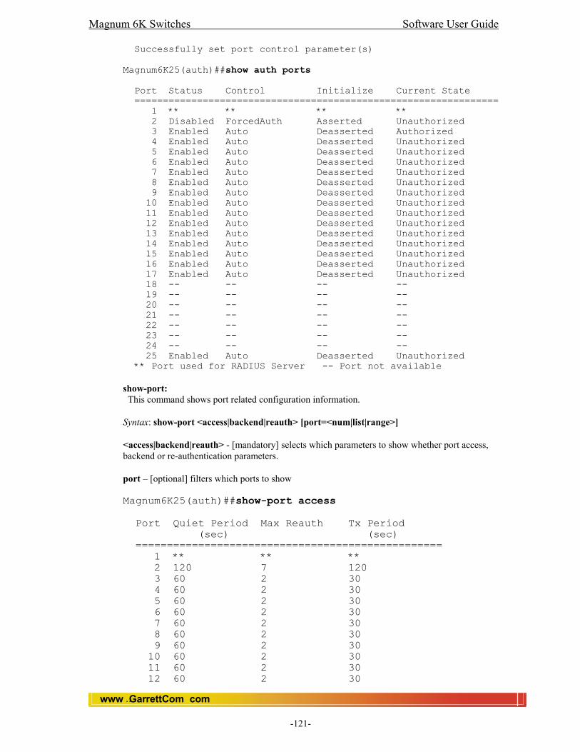
Magnum 6K Switches Software User Guide
www GarrettCom com..
-121-
Successfully set port control parameter(s) Magnum6K25(auth)##show auth ports Port Status Control Initialize Current State ================================================================ 1 ** ** ** ** 2 Disabled ForcedAuth Asserted Unauthorized 3 Enabled Auto Deasserted Authorized 4 Enabled Auto Deasserted Unauthorized 5 Enabled Auto Deasserted Unauthorized 6 Enabled Auto Deasserted Unauthorized 7 Enabled Auto Deasserted Unauthorized 8 Enabled Auto Deasserted Unauthorized 9 Enabled Auto Deasserted Unauthorized 10 Enabled Auto Deasserted Unauthorized 11 Enabled Auto Deasserted Unauthorized 12 Enabled Auto Deasserted Unauthorized 13 Enabled Auto Deasserted Unauthorized 14 Enabled Auto Deasserted Unauthorized 15 Enabled Auto Deasserted Unauthorized 16 Enabled Auto Deasserted Unauthorized 17 Enabled Auto Deasserted Unauthorized 18 -- -- -- -- 19 -- -- -- -- 20 -- -- -- -- 21 -- -- -- -- 22 -- -- -- -- 23 -- -- -- -- 24 -- -- -- -- 25 Enabled Auto Deasserted Unauthorized ** Port used for RADIUS Server -- Port not available show-port: This command shows port related configuration information.
Syntax: show-port <access|backend|reauth> [port=<num|list|range>]
<access|backend|reauth> - [mandatory] selects which parameters to show whether port access, backend or re-authentication parameters.
port – [optional] filters which ports to show Magnum6K25(auth)##show-port access Port Quiet Period Max Reauth Tx Period (sec) (sec) ================================================= 1 ** ** ** 2 120 7 120 3 60 2 30 4 60 2 30 5 60 2 30 6 60 2 30 7 60 2 30 8 60 2 30 9 60 2 30 10 60 2 30 11 60 2 30 12 60 2 30
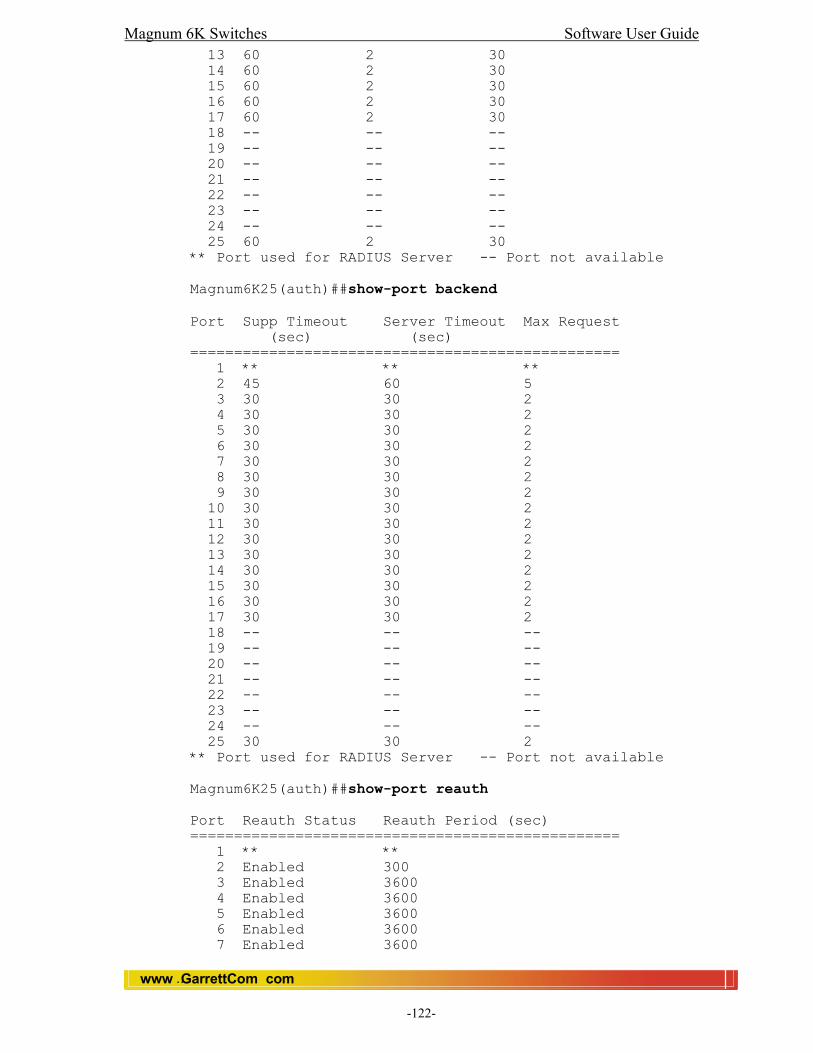
Magnum 6K Switches Software User Guide
www GarrettCom com..
-122-
13 60 2 30 14 60 2 30 15 60 2 30 16 60 2 30 17 60 2 30 18 -- -- -- 19 -- -- -- 20 -- -- -- 21 -- -- -- 22 -- -- -- 23 -- -- -- 24 -- -- -- 25 60 2 30 ** Port used for RADIUS Server -- Port not available Magnum6K25(auth)##show-port backend Port Supp Timeout Server Timeout Max Request (sec) (sec) ================================================= 1 ** ** ** 2 45 60 5 3 30 30 2 4 30 30 2 5 30 30 2 6 30 30 2 7 30 30 2 8 30 30 2 9 30 30 2 10 30 30 2 11 30 30 2 12 30 30 2 13 30 30 2 14 30 30 2 15 30 30 2 16 30 30 2 17 30 30 2 18 -- -- -- 19 -- -- -- 20 -- -- -- 21 -- -- -- 22 -- -- -- 23 -- -- -- 24 -- -- -- 25 30 30 2 ** Port used for RADIUS Server -- Port not available Magnum6K25(auth)##show-port reauth Port Reauth Status Reauth Period (sec) ================================================= 1 ** ** 2 Enabled 300 3 Enabled 3600 4 Enabled 3600 5 Enabled 3600 6 Enabled 3600 7 Enabled 3600

Magnum 6K Switches Software User Guide
www GarrettCom com..
-123-
8 Enabled 3600 9 Enabled 3600 10 Enabled 3600 11 Enabled 3600 12 Enabled 3600 13 Enabled 3600 14 Enabled 3600 15 Enabled 3600 16 Enabled 3600 17 Enabled 3600 18 -- -- 19 -- -- 20 -- -- 21 -- -- 22 -- -- 23 -- -- 24 -- -- 25 Enabled 3600 ** Port used for RADIUS Server -- Port not available show-stats: This commands displays per-port authentication statistics. Syntax: show-stats port=<num> Magnum6K25(auth)##show-stats port=3 Port 3 Authentication Counters authEntersConnecting : 3 authEapLogoffsWhileConnecting : 0 authEntersAuthenticating : 3 authAuthSuccessesWhileAuthenticating : 2 authAuthTimeoutsWhileAuthenticating : 0 authAuthFailWhileAuthenticating : 0 authAuthReauthsWhileAuthenticating : 0 authAuthEapStartsWhileAuthenticating : 1 authAuthEapLogoffWhileAuthenticating : 0 authAuthReauthsWhileAuthenticated : 0 authAuthEapStartsWhileAuthenticated : 0 authAuthEapLogoffWhileAuthenticated : 0 backendResponses : 5 backendAccessChallenges : 2 backendOtherRequestsToSupplicant : 0 backendNonNakResponsesFromSupplicant : 2 backendAuthSuccesses : 2 backendAuthFails : 0 trigger-reauth : This command manually initiates a re-authentication of supplicant.
Syntax: trigger-reauth port=<num|list|range>
Magnum6K25(auth)##trigger-reauth port=3
Successfully triggered re-authentication
Magnum 6K Switches Software User Guide
www GarrettCom com..
-124-
21.5 Web: View and Configure 802.1x
In the web browser interface: 1. Click on the [Configuration]. 2. Click on [802.1x]. 3. Click on [Server]. 4. Click on [EDIT] to add or edit Radius Server information. 5. After you make the desired changes, click on [OK] button. 7. Click [Save] to save the configuration.
For 802.1x Port Settings 1. Click on the [Configuration]. 2. Click on [802.1x]. 3. Click on [Port]. 4. Click on [Set/Access/Backend/Reauth/Stat] to add or edit the information. 5. After you make the desired changes, click on [OK] button. 7. Click [Save] to save the configuration.

Magnum 6K Switches Software User Guide
www GarrettCom com..
-125-
22.0 TACACS+ (Terminal Access Controller Access Control System) 22.1 Introduction
TACACS+, short for Terminal Access Controller Access Control System, protocol provides access control for routers, network access servers and other networked computing devices via one or more centralized servers. TACACS+ provides separate authentication, authorization and accounting services.
22.2 History TACACS allows a client to accept a username and password and send a query to a TACACS authentication server, sometimes called a TACACS daemon (server) or simply TACACSD. This server was normally a program running on a host. The host would determine whether to accept or deny the request and sent a response back. The TACACS+ protocol is the latest generation of TACACS. TACACS is a simple UDP (User Datagram Protocol) based access control protocol originally developed by BBN for the MILNET (Military Network). Cisco has enhanced (extended) TACACS several times and Cisco's implementation, based on the original TACACS, is referred to as XTACACS. Later it enhanced to TACACS+. TACACS+ is a TCP (Transmission Control Protocol) based access control protocol. TCP offers a connection-oriented transport, while UDP offers best-effort delivery.
22.3 Overview TACACS+ improves on TACACS and XTACACS by separating the functions of authentication, authorization and accounting and by encrypting all traffic between the NAS (Network Access Server) and the TACACS+ daemon. It allows for arbitrary length and content authentication exchanges, which allows any authentication mechanism to be utilized with TACACS+ clients. It is extendable to provide for site customization and future development features and it uses TCP to ensure reliable delivery. The protocol allows the TACACS+ client to request very fine-grained access control and allows the daemon to respond to each component of that request. The Magnum 6K switch implements a TACACS+ client that integrates neatly with its local access control.
TACACS+ and TCP TACACS+ servers or daemons use TCP Port 49 for listening to client requests. Clients connect to this port number to send authentication and authorization packets.
22.4 Magnum 6K TACACS+ The Magnum 6K switches uses and integrates the TACACS+ client authentication and authorization to control access login to management control agent. With TACACS+, the Magnum 6K switch can use network-based user authentication thus allowing multiple switches with refers to a common user database. The figure below shows the basic TACACS+ enabled network.

Magnum 6K Switches Software User Guide
www GarrettCom com..
-126-
Magnum 6K TACACS+ Basic Topology
In the networked picture above, two Magnum 6K switches are configured to connect to two TACACS+ servers in the network. Note: Each Magnum 6K switch can be configured to connect to up to five TACACS+ servers. Whether through serial console or telnet, a user is authenticated following the flow diagram below.
6K Switch 1
Serial Console
Network
TACACS+ Server 2
Telnet Console
6K Switch 2
TACACS+ Server 1
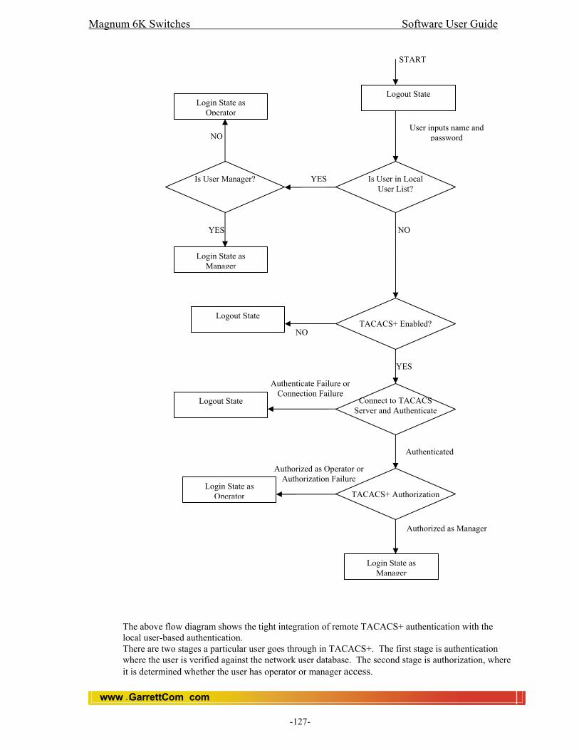
Magnum 6K Switches Software User Guide
www GarrettCom com..
-127-
The above flow diagram shows the tight integration of remote TACACS+ authentication with the local user-based authentication. There are two stages a particular user goes through in TACACS+. The first stage is authentication where the user is verified against the network user database. The second stage is authorization, where it is determined whether the user has operator or manager access.
Logout State
User inputs name and password
Is User in Local User List?
YES Is User Manager?
YES
Login State as Manager
Login State as Operator
NO
NO
TACACS+ Enabled? NO
Logout State
START
YES
Connect to TACACS Server and Authenticate
Authenticate Failure or Connection Failure
Logout State
Authenticated
TACACS+ Authorization
Authorized as Operator or Authorization Failure
Login State as Operator
Authorized as Manager
Login State as Manager
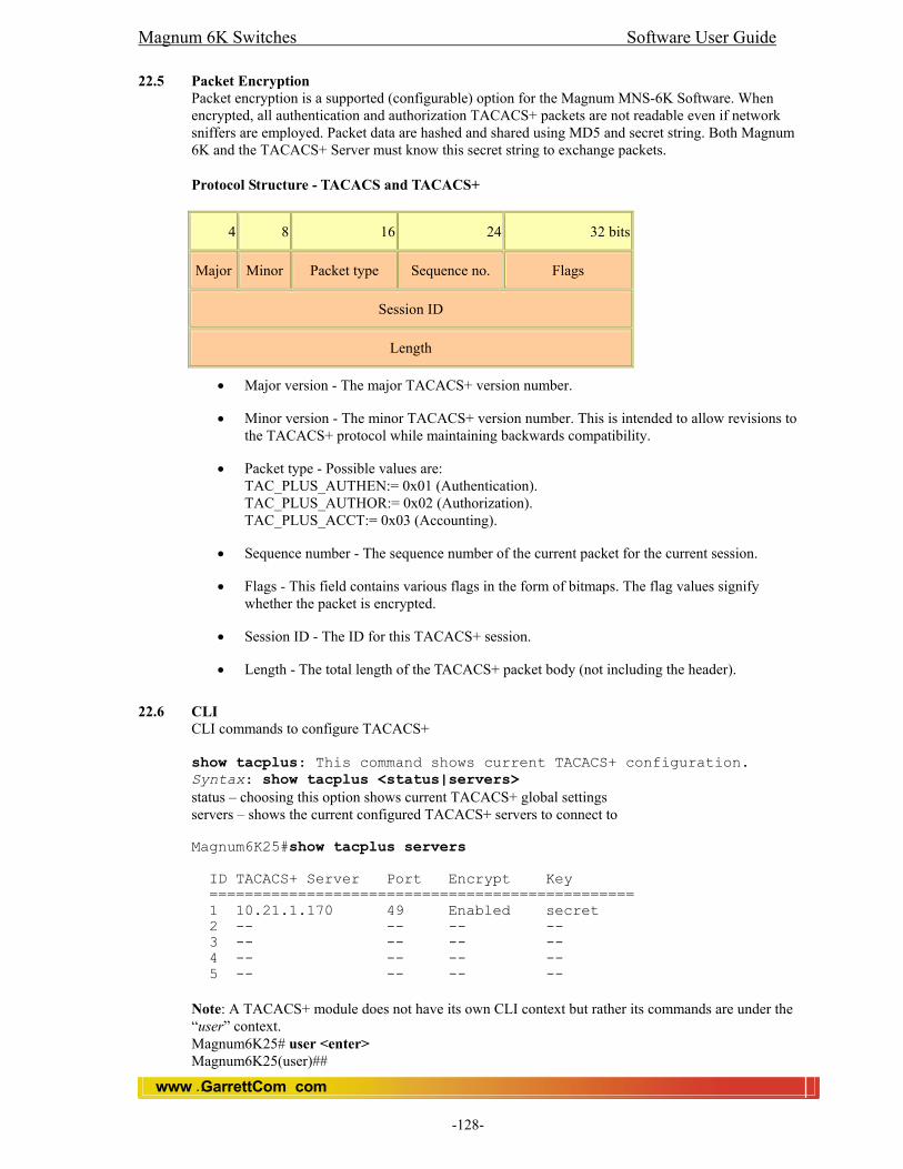
Magnum 6K Switches Software User Guide
www GarrettCom com..
-128-
22.5 Packet Encryption
Packet encryption is a supported (configurable) option for the Magnum MNS-6K Software. When encrypted, all authentication and authorization TACACS+ packets are not readable even if network sniffers are employed. Packet data are hashed and shared using MD5 and secret string. Both Magnum 6K and the TACACS+ Server must know this secret string to exchange packets. Protocol Structure - TACACS and TACACS+
4 8 16 24 32 bits
Major Minor Packet type Sequence no. Flags
Session ID
Length
• Major version - The major TACACS+ version number.
• Minor version - The minor TACACS+ version number. This is intended to allow revisions to the TACACS+ protocol while maintaining backwards compatibility.
• Packet type - Possible values are: TAC_PLUS_AUTHEN:= 0x01 (Authentication). TAC_PLUS_AUTHOR:= 0x02 (Authorization). TAC_PLUS_ACCT:= 0x03 (Accounting).
• Sequence number - The sequence number of the current packet for the current session.
• Flags - This field contains various flags in the form of bitmaps. The flag values signify whether the packet is encrypted.
• Session ID - The ID for this TACACS+ session.
• Length - The total length of the TACACS+ packet body (not including the header).
22.6 CLI
CLI commands to configure TACACS+ show tacplus: This command shows current TACACS+ configuration. Syntax: show tacplus <status|servers> status – choosing this option shows current TACACS+ global settings servers – shows the current configured TACACS+ servers to connect to Magnum6K25#show tacplus servers ID TACACS+ Server Port Encrypt Key ================================================ 1 10.21.1.170 49 Enabled secret 2 -- -- -- -- 3 -- -- -- -- 4 -- -- -- -- 5 -- -- -- -- Note: A TACACS+ module does not have its own CLI context but rather its commands are under the “user” context. Magnum6K25# user <enter> Magnum6K25(user)##

Magnum 6K Switches Software User Guide
www GarrettCom com..
-129-
Tacplus: This command enables or disables TACACS+. Syntax: tacplus <enable|disable> <enable|disable> – [mandatory] Enables or disables TACACS+. Magnum6K25(user)##tacplus enable TACACS+ is enabled. Magnum6K25(user)##tacplus disable TACACS+ Tunneling is disabled. Tacserver: This command adds or deletes a TACACS+ server in the list. Syntax: tacserver <add|delete> id=<num> [ip=<ip-addr>] [port=<tcp-port>] [encrypt=<enable|disable>] [key=<string>] <add|delete> – [mandatory] adds or delete a TACACS+ server. id – [mandatory] the ID number in the TACACS+ table ip – [mandatory for add] the IP address of the TACACS+ server port – [optional for add] TCP port number where the server is listening encrypt – [optional for add] enable or disable packet encryption key – [optional for add] when encryption is enabled, the secret shared key string must be supplied. Magnum6K25(user)##tacserver add id=2 ip=10.21.1.123 encrypt=enable key=secret TACACS+ server is added. Magnum6K25(user)##show tacplus servers ID TACACS+ Server Port Encrypt Key ================================================ 1 10.21.1.170 49 Enabled secret 2 10.21.1.123 49 Enabled secret 3 -- -- -- -- Magnum6K25(user)##tacserver delete id=2 TACACS+ server is deleted. Magnum6K25(user)##show tacplus servers ID TACACS+ Server Port Encrypt Key ================================================ 1 10.21.1.170 49 Enabled secret 2 -- -- -- -- 3 -- -- -- -- 4 -- -- -- -- 5 -- -- -- --
22.7 Web: View and Configure 802.1x
In the web browser interface: 1. Click on the [Administration]. 2. Click on [User Mgmt]. 3. Click on [TACACS+]. 4. Click on [ADD] to add or edit Server information. 5. After you make the desired changes, click on [OK] button. 7. Click [Save] to save the configuration.

Magnum 6K Switches Software User Guide
www GarrettCom com..
-130-
23.0 Troubleshooting 23.1 Overview This chapter addresses performance-related network problems that can be caused by topology, Switch configuration, and the effects of other devices or their configurations on Switch operation. (For Switch-specific information on hardware problems indicated by LED behavior, cabling requirements, and other potential hardware-related problems, refer to the Magnum 6K Switches User Manual.)
This chapter includes: • Troubleshooting Approaches • Console Interface Problems • Unusual Network Activity • General Problems • VLAN-Related Problems • Using the Event Log To Identify Problem Sources • Diagnostics and Management Tools, including: • Ping test • Command prompt • Restoring the factory default configuration For information on support and warranty provisions, see the Magnum 6K Switches User Manual
23.2 Troubleshooting Approaches
Use these approaches to diagnose Switch problems: • Check the Switch LEDs for indications of proper Switch operation: • Each Switch port has a Link LED that should light whenever an active network
device is connected to the port.
See the Hardware User Guide shipped with the Switch for a description of the LED behavior and information on using the LEDs for trouble-shooting.
• Check the network topology/installation. See the Hardware User Guide shipped
with the Switch for topology information.
• Check cables for visible damage, correct type, and proper connections. See the Hardware User Guide shipped with the Switch for correct cable types and
connector pin-outs.
• For help in isolating problems, use the easy-to-access console port built into the Switch. See chapter 2, “Using the Console Interface” for operating information.
These tools are available through the console port.
• Status and Counters screens • Event Log • Diagnostics tools (Ping test, and advanced user commands)
23.3 Console Access Problems
The Switch may not have the correct IP address, subnet mask, or gateway. Verify the problem by connecting a console to the Switch’s Console port and check the IP configuration.
23.4 Unusual Network Activity
Network activity that exceeds accepted norms may indicate a hardware problem with one or more of the network components, possibly including the Switch. Unusual network activity is indicated by the light patterns of the LEDs on the front of the Switch. This unusual activity can be measured with the Switch console interface or with a network management tool. Refer to the Hardware User Guide you received with the Switch for information on using LEDs to identify unusual network activity.
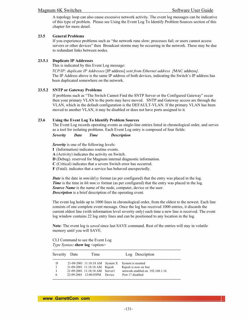
Magnum 6K Switches Software User Guide
www GarrettCom com..
-131-
A topology loop can also cause excessive network activity. The event log messages can be indicative of this type of problem. Please see Using the Event Log To Identify Problem Sources section of this chapter for more detail.
23.5 General Problems If you experience problems such as “the network runs slow; processes fail; or users cannot access servers or other devices” then Broadcast storms may be occurring in the network. These may be due to redundant links between nodes.
23.5.1 Duplicate IP Addresses This is indicated by this Event Log message: TCP/IP: duplicate IP Addresses [IP address] sent from Ethernet address [MAC address]. The IP Address above is the same IP address of both devices, indicating the Switch’s IP address has been duplicated somewhere on the network.
23.5.2 SNTP or Gateway Problems If problems such as “The Switch Cannot Find the SNTP Server or the Configured Gateway” occur then your primary VLAN to the ports may have moved. SNTP and Gateway access are through the VLAN, which in the default configuration is the DEFAULT-VLAN. If the primary VLAN has been moved to another VLAN, it may be disabled or does not have ports assigned to it.
23.6 Using the Event Log To Identify Problem Sources
The Event Log records operating events as single-line entries listed in chronological order, and serves as a tool for isolating problems. Each Event Log entry is composed of four fields: Severity Date Time Description Severity is one of the following levels: I (Information) indicates routine events. A (Activity) indicates the activity on Switch. D (Debug). reserved for Magnum internal diagnostic information. C (Critical) indicates that a severe Switch error has occurred. F (Fatal). indicates that a service has behaved unexpectedly. Date is the date in mm/dd/yy format (as per configured) that the entry was placed in the log. Time is the time in hh:mm:ss format (as per configured) that the entry was placed in the log. Source Name is the name of the node, computer, device or the user. Description is a brief description of the operating event. The event log holds up to 1000 lines in chronological order, from the oldest to the newest. Each line consists of one complete event message. Once the log has received 1000 entries, it discards the current oldest line (with information level severity only) each time a new line is received. The event log window contains 22 log entry lines and can be positioned to any location in the log. Note: The event log is saved since last SAVE command. Rest of the entries will stay in volatile memory until you will SAVE. CLI Command to see the Event Log Type Syntax: show log <option> ---------------------------------------------------------------------------------------------- Severity Date Time Log Description ---------------------------------------------------------------------------------------------- D 21-09-2001 11:18:18 AM System X System is resetted I 21-09-2001 11:18:18 AM Rajesh Rajesh is now on line I 21-09-2001 11:18:18 AM Server1 network enabled on 192.168.1.16 A 22-09-2001 12:00:03PM Device Port 17 disabled ----------------------------------------------------------------------------------------------
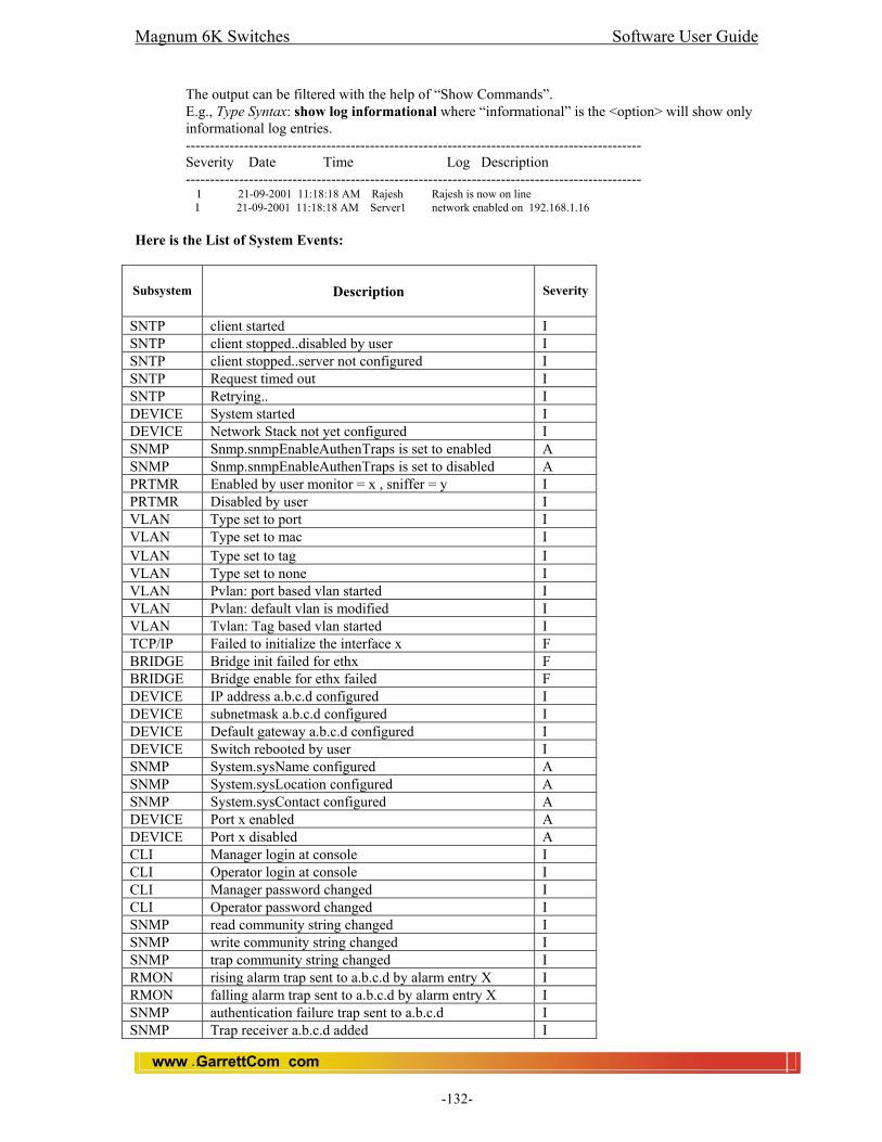
Magnum 6K Switches Software User Guide
www GarrettCom com..
-132-
The output can be filtered with the help of “Show Commands”. E.g., Type Syntax: show log informational where “informational” is the <option> will show only informational log entries. ---------------------------------------------------------------------------------------------- Severity Date Time Log Description ---------------------------------------------------------------------------------------------- I 21-09-2001 11:18:18 AM Rajesh Rajesh is now on line
I 21-09-2001 11:18:18 AM Server1 network enabled on 192.168.1.16
Here is the List of System Events:
Subsystem
Description
Severity
SNTP client started I SNTP client stopped..disabled by user I SNTP client stopped..server not configured I SNTP Request timed out I SNTP Retrying.. I DEVICE System started I DEVICE Network Stack not yet configured I SNMP Snmp.snmpEnableAuthenTraps is set to enabled A SNMP Snmp.snmpEnableAuthenTraps is set to disabled A PRTMR Enabled by user monitor = x , sniffer = y I PRTMR Disabled by user I VLAN Type set to port I VLAN Type set to mac I VLAN Type set to tag I VLAN Type set to none I VLAN Pvlan: port based vlan started I VLAN Pvlan: default vlan is modified I VLAN Tvlan: Tag based vlan started I TCP/IP Failed to initialize the interface x F BRIDGE Bridge init failed for ethx F BRIDGE Bridge enable for ethx failed F DEVICE IP address a.b.c.d configured I DEVICE subnetmask a.b.c.d configured I DEVICE Default gateway a.b.c.d configured I DEVICE Switch rebooted by user I SNMP System.sysName configured A SNMP System.sysLocation configured A SNMP System.sysContact configured A DEVICE Port x enabled A DEVICE Port x disabled A CLI Manager login at console I CLI Operator login at console I CLI Manager password changed I CLI Operator password changed I SNMP read community string changed I SNMP write community string changed I SNMP trap community string changed I RMON rising alarm trap sent to a.b.c.d by alarm entry X I RMON falling alarm trap sent to a.b.c.d by alarm entry X I SNMP authentication failure trap sent to a.b.c.d I SNMP Trap receiver a.b.c.d added I

Magnum 6K Switches Software User Guide
www GarrettCom com..
-133-
SNMP Trap receiver a.b.c.d deleted I DEVICE No saved system logs I DEVICE Failed to read saved system logs D SNMP Coldstart trap sent to a.b.c.d I SNMP Warmstart trap sent to a.b.c.d I SNMP Port X link up trap sent to a.b.c.d A SNMP Port X Link down trap sent to a.b.c.d A SNMP Configuring IP address in trap receivers list failed D DEVICE Timezone set to x I DEVICE Country set to x (no DST) I DEVICE Country set to x (DST valid) I DEVICE Time set to x : y : z (HH:MM:SS) tz = a I DEVICE Date set to x : y : z (HH:MM:YYYY) I RMON RMON init is done I BRIDGE Bridge MIB init is done I TCP/IP Duplicate IP a.b.c.d sent from MAC address
XXXXXX C
TCP/IP IP packet of version X is dropped I TCP/IP IP packet from a.b.c.d , with checksum error dropped D TCP/IP Bad IP fragments from a.b.c.d dropped D TCP/IP UDP checksum error in the received packet a.b.c.d D TCP/IP TCP checksum error in the received packet a.b.c.d D TCP/IP Unable to allocate memory for an ICMP packet C TCP/IP ICMP checksum error in the received packet D SNTP Time synchronized through SNTP I RMON history : control entry X is set to valid I RMON history : control entry X is set to invalid I RMON Event : entry X is set to valid I RMON Event : entry X is set to invalid I RMON Alarm : entry X is set to valid I RMON Alarm : entry X is set to invalid I RMON Alarm : internal error , unable to get memory F RMON Alarm : internal error, unable to get memory for
alarm entry F
RMON History : internal error, unable to get memory for history control entry
F
RMON History : internal error, unable to get memory for history data entry
F
RMON History : internal error, unable to get memory F RMON Event : unable to get memory for event entry F RMON Alarm : unable to get memory for RMON logs F DEVICE Ethernet DMA init failure F DEVICE Ethernet hardware error F DEVICE Ethernet interrupt init failure F DEVICE Ethernet counters init failure C BRIDGE Unable to delete MAC address from FDB D BRIDGE Unable to insert MAC address to FDB D DEVICE Unable to access ethernet counters C DEVICE Unable to allocate ethernet memory F DEVICE Port X link down A DEVICE Port X link up A PS INTRUDER a:b:c:d:e:f @ port X , port disabled A PS INTRUDER a:b:c:d:e:f @ port X , port disabled A PS Resetting MAC a:b:c:d:e:f at port X failed C PS Unable to delete learnt MACs in hardware D PS Port security enabled A
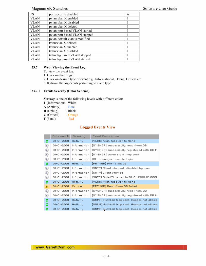
Magnum 6K Switches Software User Guide
www GarrettCom com..
-134-
PS port security disabled A VLAN pvlan:vlan X enabled I VLAN pvlan:vlan X disabled I VLAN pvlan:vlan X deleted I VLAN pvlan:port based VLAN started I VLAN pvlan:port based VLAN stopped I VLAN pvlan:default vlan is modified I VLAN tvlan:vlan X deleted I VLAN tvlan:vlan X enabled I VLAN tvlan:vlan X disabled I VLAN tvlan:tag based VLAN stopped I VLAN tvlan:tag based VLAN started I 23.7 Web: Viewing the Event Log
To view the event log: 1. Click on the [Logs]. 2. Click on desired type of event e.g., Informational, Debug, Critical etc. 3. It shows the log events pertaining to event type.
23.7.1 Events Severity (Color Scheme)
Severity is one of the following levels with different color: I (Information) - White A (Activity) - Blue D (Debug) - Black C (Critical) - Orange F (Fatal) - Red
Logged Events View
Magnum 6K Switches Software User Guide
www GarrettCom com..
-135-
23.8 Diagnostic Tools 23.8.1 Ping Test
The Ping test is a point-to-point test between your Switch and another IEEE 802.3-compliant device on your network. These tests can tell you whether the Switch is communicating properly with another device. Note: To respond to a Ping test or a Link test, the device you are trying to reach must be IEEE 802.3-compliant. This is a test of the path between the Switch and another device on the same or another IP network that can respond to IP packets (ICMP Echo Requests).
23.8.2 CLI: Ping Test Ping Test. You can issue single or multiple ping tests with varying repetitions or counts and timeout periods. The defaults and ranges are: _ Count: 1 (1 - 999) _ Timeout: 5 seconds (1 - 256 seconds) Syntax: ping <ipaddress> [count=<1-999>] [timeout=<1-256>] Example: Magnum 6K25> ping 192.168.1.10 Your response will be 192.168.1.10 is alive, time=15ms Example 2: Magnum 6K25> ping 192.168.1.10 count=3 Your response will be 192.168.1.10 is alive, time=15ms 192.168.1.10 is alive, time=15ms 192.168.1.10 is alive, time=15ms You can do any combination of the above IP address, count, and timeout commands. To halt a ping test before it concludes, press [Ctrl] [C].
23.9 CLI Administrative and Troubleshooting Commands These commands provide information or perform actions that you may find helpful in troubleshooting operating problems with the Switch. Note For more on the CLI, refer to chapter 2, "Using the Command Line Reference (CLI). Type Syntax: show version shows the software version currently running on the Switch. Similarly Type Syntax: show history Displays the current command history. Type Syntax: show setup Displays the Switch Setup screen. Type Syntax: !! Repeatedly executes the previous command.

Magnum 6K Switches Software User Guide
www GarrettCom com..
-136-
APPENDIX A Daylight Savings Time on Magnum Switches
Magnum6K Switches provide a way to automatically adjust the system clock for Daylight Savings Time (DST) changes. The user defines the month and date to begin and end the change from standard time. In addition to the value "none" (no time changes), there are fifteen pre-defined settings, a few examples are:
Alaska Canada and Continental US Middle Europe and Portugal Southern Hemisphere Western Europe
The pre-defined settings follow these rules: Alaska: • Begin DST at 2am the first Sunday on or after April 24th. • End DST at 2am the first Sunday on or after October 25th. Canada and Continental US: • Begin DST at 2am the first Sunday on or after April 1st. • End DST at 2am the first Sunday on or after October 25th. Middle Europe and Portugal: • Begin DST at 2am the first Sunday on or after March 25th. • End DST at 2am the first Sunday on or after September 24th. Southern Hemisphere: • Begin DST at 2am the first Sunday on or after October 25th. • End DST at 2am the first Sunday on or after March 1st. Western Europe: • Begin DST at 2am the first Sunday on or after March 23rd. • End DST at 2am the first Sunday on or after October 23rd. A sixth option named "User defined" allows the user to customize the DST configuration by entering the beginning month and date plus the ending month and date for the time change. Before configuring a "User defined" Daylight Time Rule, it is important to understand how the Switch treats the entries. The Switch knows which dates are Sundays, and uses an algorithm to determine on which date to change the system clock, given the configured "Beginning day" and "Ending day":
• If the configured day is a Sunday, the time changes at 2am on that day. • If the configured day is not a Sunday, the time changes at 2am on the first Sunday
after the configured day. This is true for both the "Beginning day" and the "Ending day". List of valid country codes to set daylight settings
Egypt Namibia USSR Iraq Lebanon Syria Australia London Belgium Italy Greece Cuba USA Falklands Chile

Magnum 6K Switches Software User Guide
www GarrettCom com..
-137-
APPENDIX B How to Upgrade
Magnum 6K Managed Network Software (MNS) can be obtained from GarrettCom FTP site (ftp.garrettcom.com) Username: m6kuser, Password: m6kuser and uploaded to the Magnum 6K Switch unit. The upgrade feature of the Magnum 6K is provided for facilitating periodic MNS Software upgrades. MNS Software Download from FTP site Downloading Magnum 6K software (MNS) from GarrettCom’s FTP site (ftp.garrettcom.com
a. Use browser (Microsoft Internet Explorer or Netscape Navigator) or any FTP tools to download the MNS Software.
b. If you use browser interface, use the following URL to access the files: ftp://ftp.garrettcom.com
c. If you are using an FTP client program, connect to ftp.garrettcom.com d. User: m6kuser ; password: m6kuser e. Download the MNS Software on your Desktop PC (Chosen to be used as a console
terminal) Assumptions:
• The responsible person configuring this switch is well versed with Hyper Terminal (Windows 98, 2000, XP) or Minicom (Linux).
Note: For Linux/Unix Minicom Configuration instructions, please refer to page g below. • The 6K Switch must be connected via the console RS-232 port (located on the
right rear of the unit as shown in Fig 1.0) to a serial port of a Desktop PC operating as a console terminal.
Note:(The DB-9 (Null Modem) connecting cable is required for the connection. It is not supplied along with the Magnum6K unit). It can be purchased from any Electronic Store.
Connecting the Console Terminal to Magnum6K Use the DB-9 cable to connect the Magnum6K Switch Console (RS-232) port to the Desktop PC (Console Terminal). Caution: While connecting the DB9 cable to the Magnum6K unit, the unit must be switched off. On Desktop PC (Windows Console) Follow these steps to connect the Desktop PC or terminal to the Magnum6K Switch: Step 1: Using the DB9 cable, connect to the Magnum 6K console port, as shown in the Fig. 1.0 below Fig 1.0 Step 2: Attach the other end of the DB-9 female adapter to the Desktop PC (COM1, COM2 or COM3 Port). Step 3: Run Hyper Terminal on the Desktop PC. Step 4: Provide an appropriate name and Press OK then connect to the serial port using COM1, COM2 or COM3 (as provided on Desktop PC) and Press OK. Step 5: Configure the following parameters as shown in the Fig 1.0:
• 38400 baud • 8 data bits • 1 stop bit • No parity • None
AC PowerPower Connector
ON
OFF
110-220 VAC
47-63Hz 1.0-0.5A
Rear View of Magnum 6K25
CONSOLE PORT

Magnum 6K Switches Software User Guide
www GarrettCom com..
-138-
Fig 2.0
Step 6: Power on the Magnum6K Switch and obtain the Magnum6K25# prompt on the Hyper Terminal window. Step 7: Invoke the upgrade command by typing "upgrade" without any arguments and press enter key as shown below. Magnum6K25# upgrade mode=serial <enter> Step 8: From the Hyper Terminal Menu, Select Transfer -> Send File -> a small popup window opens... use Browse button to locate your path to the MNS Software file (Rel2.x.x.bin) location, and select the protocol as Xmodem from the drop down list, then click Ok. Step 9: The download starts and proceeds to download the file. You will get the message " Upgrade is Successful. Please reboot Magnum6K now to start the application” at the end. If there is any error in the file transfer, you will get the error message " Upgrade failed " and the program will abort back to the (boot) prompt. NOTE: Please do not interrupt the Magnum6K unit or the Desktop PC during the download process. If for any reason the download is not complete, please follow steps 6 through 9 again to complete the upgrade process. On Linux Console Step 1: Run Minicom. Step 2: To set the baud rate of the COM Port. Press <ctrl> A …Z…P…G and <Enter> Step 3: Power on the Magnum6K Switch. You will get the Prompt Magnum6K25#
Step 4: Invoke the upgrade command by typing "upgrade" without any arguments and press enter key as shown below. Magnum6K25# upgrade mode=serial <enter>
Step 5: Press <ctrl>A…S, Select xmodem from the Popup window and press <enter>. Select [Go To] Tab and <Enter> Step 6: You will get the window asking for the Directory. Give the full path of the directory where you have copied the Image file to upload and press <enter>.

Magnum 6K Switches Software User Guide
www GarrettCom com..
-139-
Step 7: Select the file with the help of the spacebar and Press <Enter>. The download starts and proceeds to download the file.… At the end of the transfer close the progress indicator window. Step 8: The download starts and proceeds to download the file. You will get the message " Upgrade is Successful. Please reboot Magnum6K now to start the application” at the end. If there is any error in the file transfer, you will get the error message " Upgrade failed " and the program will abort back to the (boot) prompt. To Check the Successful Upgrade: Once you restart the switch, you will get the login prompt on the Hyper Terminal (as shown below).
And check the version number using ‘show version’ command. Syntax: show version Magnum6K25#show version Version Rel3.0.0, Build Date: Sep 03 2004, Time: 15:15:59
Upgrade over the Network You can upgrade the software over the Network using TFTP or FTP protocol. Syntax: upgrade mode=<serial|tftp|ftp> [<ipaddress>] [file=<Name>] [user=<username>] [ pass=<password>] Boot Code Upgrade Boot code upgrade is a part of software upgrade. Once the software upgrade done, it checks for the boot code. If there is an old boot code, software will ask for upgrade. The BOOT Flash Code needs updating. This application is capable of updating the BOOT Flash. To avoid problems, make sure that you have an uninterrupted power supply to the switch. Upgrade Boot code? <y/n> If you press ‘Y’, it starts writing a boot code on Flash. Successfully Created Boot Image. Proceeding to Write Flash. Boot Flash Updated. Restart the System You can also upgrade the boot code from CLI command. Syntax: upgrade mode=bl Magnum6K25#upgrade mode=bl Note: The BOOT Flash image will be replaced by the version which is embedded in the application. Do you wish to upgrade the image? [ 'Y' or 'N'] If you press ‘Y’, it starts writing a boot code on Flash. Uncompressing image and programming flash memory. This will take up to a minute to complete... Boot loader upgrade is successful...

Magnum 6K Switches Software User Guide
www GarrettCom com..
-140-
Corporate Headquarters
GarrettCom, Inc. 213 Hammond Ave. Fremont, CA 94539 Phone (510) 438-9071 Fax (510) 438-9072 Website: http://www.GarrettCom.com
email [email protected]