magnetically sensitive precision-alloy components
TRANSCRIPT
ISSN 0967�0912, Steel in Translation, 2010, Vol. 40, No. 12, pp. 1119–1124. © Allerton Press, Inc., 2010.Original Russian Text © A.F. Prokoshin, V.V. Sadchikov, V.V. Luzanov, 2010, published in “Stal’,” 2010, No. 12, pp. 64–68.
1119
† Both natural and artificial electromagnetic fieldsrun through the Earth and the surrounding space.The induction of the constant field at the center ofthe Earth is estimated at 100 T; the value at the sur�face is around 0.1 mT. The frequency of natural andengineering alternating fields may be in the giga�hertz range, while their amplitude depends consid�erably on global factors and human activities, whoseinfluence is significant but not fully understood. Thishas prompted efforts to create high�sensitivity magne�tometers: means of measuring the induction B ofmagnetic fields and also the factors that affect it.The most important component of magnetometersis the magnetically sensitive element, which con�verts the induction to an electrical signal. Magneti�cally sensitive elements may be based on the Halland Josephson effects, on nuclear magnetic reso�nance, and many other principles, but we confineour attention here to magnetic induction and mag�netic impedance and to precision�alloy strip andmicrowire with crystalline and amorphous struc�ture. There are only a few such magnetically sensi�tive elements: the magnetic antenna, the ferro�probe, and the magnetic�impedance element.These elements differ in sensitivity dV/dB, resolvingpower ΔB, spatial resolution ΔS, speed or responsetime Δt, and energy consumption P. Foreign publi�cations regarding the properties and application ofmagnetic antennas and magnetic�impedance ele�ments were reviewed recently in [1, 2]. In thepresent work, we evaluate the contributions of Rus�sian specialists to the production of magneticantennas and investigate the nature and propertiesof magnetic�impedance elements.
Of the uncooled magnetically sensitive elements,the magnetic antenna, which is a coil with woundwire, is characterized by the greatest sensitivity, deter�
† Deceased.
mined by the cross�sectional area S, the number ofturns n, and the frequency dB/dt of the measured mag�netic field. The function V = f(B) is determined fromthe Faraday induction law
V = ndF/dt = –nSdB/dt. (1)
To increase the sensitivity dV/dB in measuring low�frequency fields, the coil diameter and the number ofwire turns must be increased. As a result, the coil massincreases to hundreds of kg. The use of a ferromagneticcore—a magnetic�flux concentrator within the coil—increases the sensitivity of antennas without increas�ing the diameter and number of wire turns. In that case
V(B) = –μcnSdB/dt, (2)
where μc = μr/[I + N(I + μr)] is the effective magneticpermeability of the core; μr is the relative magnetic per�meability of the core material; N is the demagnetizationfactor, which depends on the size and shape of the core.When μr � 1, V is determined by N. Thus, with a corelength l = 300 mm, core diameter D = 10 mm, and N ≈3.5 × 10⁻³, we obtain a value of V(B) about 300 timesgreater than in the absence of a core [1]. The resolvingpower of an antenna with a ferromagnetic core is deter�mined by the noise level, which depends significantlyon the manufacturing technology.
Specialists from Bardin Central Research Instituteof Ferrous Metallurgy and the Special Design Bureauof Radiomeasurement Equipment have developed andput into experimental production the PMP�1,PMP�2, and PMP�3 magnetic�field converters ofmagnetic�antenna type, with cores of 82K3KhSR pre�cision amorphous alloy. The PMP�3 instrument is
Magnetically Sensitive Precision�Alloy ComponentsA. F. Prokoshin†, V. V. Sadchikov, and V. V. Luzanov
Bardin Central Research Institute of Ferrous Metallurgy, Moscow, Russia
Abstract—Theoretical and experimental research on magnetically soft amorphous microwire, strip, andcomposite wire with giant magnetic impedance, conducted between 2000 and 2010 at the Institute of Theo�retical and Applied Electrodynamics (Russian Academy of Sciences), Lomonosov Moscow State University,Troitsk Institute of Innovative and Thermonuclear Research, and Bardin Central Research Institute of Fer�rous Metallurgy, is briefly reviewed. The goal of this research is to create magnetic�field converters with highsensitivity and resolving power. The materials developed are used to produce prototype sensors of weak mag�netic fields and their applicability is evaluated.
DOI: 10.3103/S0967091210120235
1120
STEEL IN TRANSLATION Vol. 40 No. 12 2010
PROKOSHIN et al.
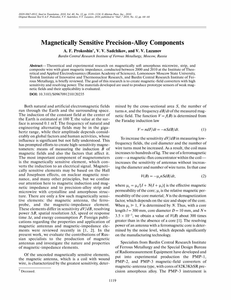
shown in Fig. 1. Its parameters compare as followswith those of the imported LEM�108 instrument [3]:
It follows that the PMP�3 instrument matches theperformance of the LEMI�108 instrument developedby the L’vovsk Center at the Ukrainian Institute ofSpace Research, except in terms of the power con�sumption and temperature range.
Magnetic�field converters of magnetic�antennatype are promising for use where limitingly highresolving power is required with relatively small spatialresolution (determined by the dimensions of the mag�netically sensitive element). This is the case in investi�gating the space around the Earth and electromagneticcompatibility, in searching for useful minerals, in seis�mic research, and elsewhere [3, 4].
At the current stage of development of magneto�metric systems, we need miniature magnetically sensi�tive elements with high spatial resolution and lowpower consumption, as well as high sensitivity andresolving power [5]. Such elements are required innavigation, nondestructive testing (in particular, ofdeep gas and oil pipelines and high�voltage transmis�
Converter PMP�3 LEMI�108
Resolving power (fT*/Hz1/2) at frequency f
1 Hz 1000 –
10 Hz 100 90
100 Hz 9 10
1 kHz 3 4
10 kHz 1 3
Power supply 12 V, 50 mA 12 V, 20 mA
Working temperature range, °C –20…+40 –40…+50
Length and diameter, mm 800 and 80 1050 and 80
Mass, kg 5 8
* 1 fT = 10–15 T.
sion lines), robotic engineering, archeology, and med�icine (in recording cardiograms, oculograms, myo�grams, and encephalograms, for example) [6]. Inthose applications, magnetically sensitive elementswith a resolving power ΔB < 1 nT are required. Of theuncooled instruments, the best options here are ferro�probes and magnetically sensitive elements based ongiant magnetic impedance, with the following charac�teristics [7, 8]:
As is evident, the magnetically sensitive elementbased on giant magnetic impedance is comparable inresolving power with the ferroprobe, but is ~100 timesbetter in terms of sensitivity, response time, and energyeconomy and ten times better in terms of spatial reso�lution (determined by the dimensions of the magneti�cally sensitive element). Disadvantages of the ferro�probe include difficulty of manufacture and high cost.Against this background, attention has lately beenfocusing on the development of compositions andmanufacturing technologies for amorphous� andnanocrystalline�alloy microwires and composite poly�crystalline�alloy wires with giant magnetic imped�ance, as well as their properties.
The magnetic�impedance effect—the dependenceof the total electrical impedance of ac ferromagneticwire Z(B) = V(B)/I(ω) on the applied longitudinalmagnetic field—was first observed in the 1930s [9]. Inthe subsequent decades, numerous studies of thiseffect appeared in Russia. (See [10], for example.)However, interest eventually waned, although therewere efforts to revive interest, under the rubric of thelongitudinal galvanomagnetic effect. (See [11], forexample.) The explosive interest in magnetic imped�ance in the 1990s may be attributed to the develop�ment of microwires and films made of amorphousmagnetically soft cobalt alloys [8]. In such alloys, thevariation in Z(B) is so large that it is described as giantmagnetic impedance. Besides microwire, there is alsointerest in strip [12] and in amorphous and nanocrystal�line multilayer structures [13]. The variation in imped�ance Z = V/I in a wire segment (radius a, length l) under
Type of magnetically sensitive element (precision alloy)
Ferroprobe (81NMA, 82NP)
Element based on giant magnetic
impedance (82K3KhSR)
Sensitivity, mV/μT 3 300
Dynamic range, mV/μT 300 300
Resolving power, pT 10 <100
Dimensions, mm 10–20 1–2
Response time, μs 100 1
Energy consumption, W 1 0.01
Fig. 1. PMP�3 magnetic�field converter.
STEEL IN TRANSLATION Vol. 40 No. 12 2010
MAGNETICALLY SENSITIVE PRECISION�ALLOY COMPONENTS 1121
an applied magnetic field Hex may be described on thebasis of classical electrodynamics [8]
(3)
(4)
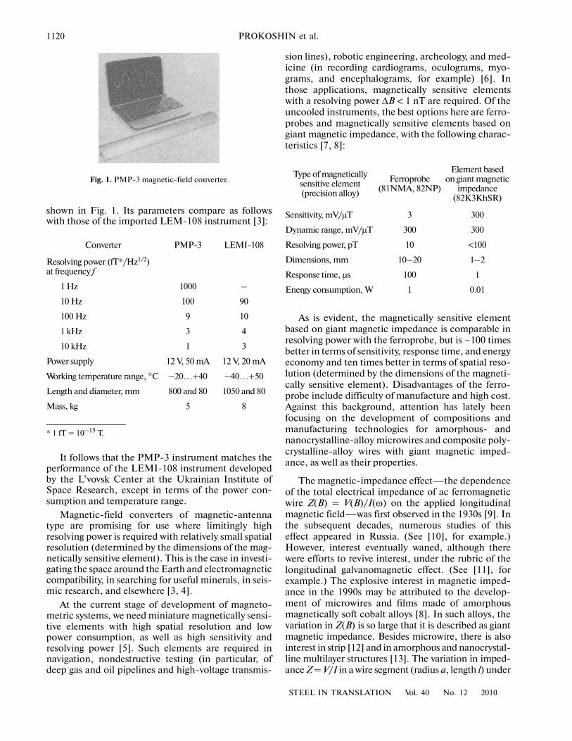
Here Rdc is the dc electrical resistance of the wire;δ is the depth of the skin layer; ρ is the electrical resis�tivity; ω is the angular frequency of current I; μθ is thecircular magnetic permeability; L is the inductance(Fig. 2).
With a linear dependence V(I), the impedance |Z| =V(ω)/I(ω) varies as follows as a function of the field
(5)
where Hmax is the external magnetic field sufficient forsaturation of Z(H).
The magnetic permeability of ferromagnetic wireμθ depends on the frequency and amplitude of thetransmitted alternating current, the magnitude anddirection of the applied magnetic field, the mechani�cal stress, and the temperature. The giant magneticimpedance is associated with a strong dependence ofthe magnetic permeability μθ(Hex) and the skin�layerdepth δ(μθ) on the applied field, when other factorsare constant. To minimize the influence of mechanicalstress, we need to control the composition of theamorphous cobalt alloys within hundredths of a per�cent so as to ensure that the magnetostriction coeffi�cient is negative but close to zero: λs ≈ –10–7. As aresult, circular magnetic anisotropy may be formed inmicrowire on thermomechanical treatment, and thelength of the magnetically sensitive element may bereduced to ~1 mm; correspondingly, the influence ofthe demagnetizing field is eliminated in this near�tor�oidal closed structure. The microwire is produced byextrusion from melt in a glass shell (the Taylor–Ulito�vsky method [14]); by spinning melt in a rotating waterlayer [15]; or by extraction of the edge of a rotatingdisk [16]. The structural uniformity of the microwireover its length and the quality of the surface layer are ofgreat importance here. Drawing through diamonddrawplates is used to eliminate surface defects. On thebasis of research on giant magnetic impedance by spe�cialists at the Institute of Theoretical and AppliedElectrodynamics (Russian Academy of Sciences),Lomonosov Moscow State University, and TroitskInstitute of Innovative and Thermonuclear Research[17–19], manufacturing methods were developed atthe Bardin Institute for two types of magnetic materi�als with giant magnetic impedance: compositemicrowire [20]; and microwire with amorphous and
Z Rdc jωL, L+ μθl/8π when= =
δ 2ρ/ωμθ( )1/2
�a=
(in the absence of a skin effect);
Z 0.5a/ 2ρ( )1/2
[ ]Rdc 1 i+( ) ωμθ( )1/2=
when δ�a
(with a strong skin effect).
ΔZ/Z 100% Z H( ) Z Hmax( )–[ ]/Z Hmax( ),=
nanocrystalline structure [21]. In addition, a methodof measuring weak magnetic fields was proposed [22].It follows from the theory of giant magnetic imped�ance in composite wire consisting of a nonmagneticcore with low electrical resistance ρco in a casing ofamorphous magnetically soft alloy with electricalresistance ρca � ρco that Z/Rdc must be increased bytwo orders of magnitude in a weak magnetic field(Hex < Ha, where Ha is the anisotropy field) [19]. Toverify the applicability of this theory to a compositewire with a casing of precision crystalline alloys 78Nand 81NMA, samples of Cu/78N, Cu/FeNbCuSiB,and Nb/81NMA composite wire were produced at theBardin Institute [23]. Several methods are known forproducing bimetallic composite wire with a permalloycasing: reduction of the metal oxides of componentsapplied to the core; ion–plasma sputtering of a targetof the corresponding composition; and a metallurgicalmethod, in which a composite blank is produced andsubjected to pressing and cold drawing [24]. The firstmethod was used to produce wire samples with a 78Npermalloy casing (thickness 0.3 μm) on copper wire(diameter 200 μm). At frequencies up to 290 MHz,ΔZ/Z(0) was less than 2%, which is insufficient for mag�netically sensitive elements. For ion–plasma sputtering,a target was made from Fe73.5Nb3Cu1Su16.5B6 (at %)alloy, which is a nanocrystalline permalloy analog.The casing thickness on a copper wire (diameter190 μm) was 0.7 μm; according to nuclear gamma res�onance in a scattering geometry with recording of theconversion electrons, the wire structure after heattreatment was of amorphous–crystalline type, with apredominance of radial magnetic anisotropy. At290 MHz, ΔZ/Z(0) was no more than 25%, and theapplication time of the layer was long (1 μm/h). Thismethod is also unpromising.
Long samples of Cu/78N and Nb/81NMA com�posite wire (diameter 50–140 mm) were produced bythe metallurgical method [24]. They were magneti�cally soft with a coercive force Hc < 80 A/m. At500 MHz, ΔZ/Z(0) was around 100% for Cu/78Ncomposite wire (diameter 50 μm), whereas the imped�
I(ω)
δ
α
l
μ
M
Hex
V(ω)
Fig. 2. Wire segment with current I(ω) and circular mag�netic permeability μ0(Hex) in an applied magnetic fieldHex. The magnetic structure of the wire consists of circulardomains [8].
1122
STEEL IN TRANSLATION Vol. 40 No. 12 2010
PROKOSHIN et al.
ance of 78N microwire is practically independent ofthe magnetic field [25]. Thus, ΔZ/Z(0) for the com�posite wire at high frequencies is comparable with thatfor cobalt amorphous alloy but does not reach the the�oretical value for composite wire with an amorphous�alloy casing [19]. These results were obtained for amagnetically sensitive element in linear mode—thatis, at small amplitudes I0 of the alternating currentthrough the wire. If I0 exceeds the threshold value Ic,nonlinear operation begins: the amplitude of the sec�ond harmonic increases sharply in the signal spectrumfrom the wire; the second harmonic is considerablymore sensitive than the first harmonic to the appliedfield Hex. In that case, almost all the current may betransmitted through the low�resistance internal coreof the composite wire, without heating of the magnet�ically sensitive element. In the ferromagnetic casing ofthe composite wire, the circular magnetic field createdby the alternating current falls on moving from theinternal region to the periphery. With appropriatechoice of the geometric parameters, this facilitatescomplete remagnetization of the casing. This must beregarded as an important benefit of composite wire[26]. A magnetically sensitive element of pin type maybe made from composite wire [27]. This design per�mits the use of the composite wire simultaneously asthe magnetic core and as the remagnetization loop. Tothis end, a ceramic pipe (diameter 1.5 mm; length10 mm) with two parallel channels (diameter 200 μm)and a Cu/78N composite wire (diameter 140 μm)were employed in [24]. At an excitation frequencyω/2π = 380 kHz, with n = 800 turns in the detectorcoil, the sensitivity dV/dB is 15 μV/nT; there is no hys�teresis; and the linearity range is 0.15 mT.
Note that this sensitivity is an order of magnitudegreater than the value assumed for such magneticallysensitive elements [27]. However, the level producedfor composite wire with circular anisotropy in the cas�
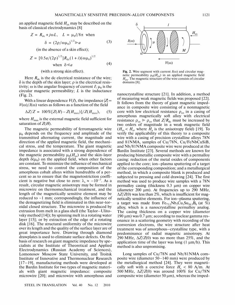
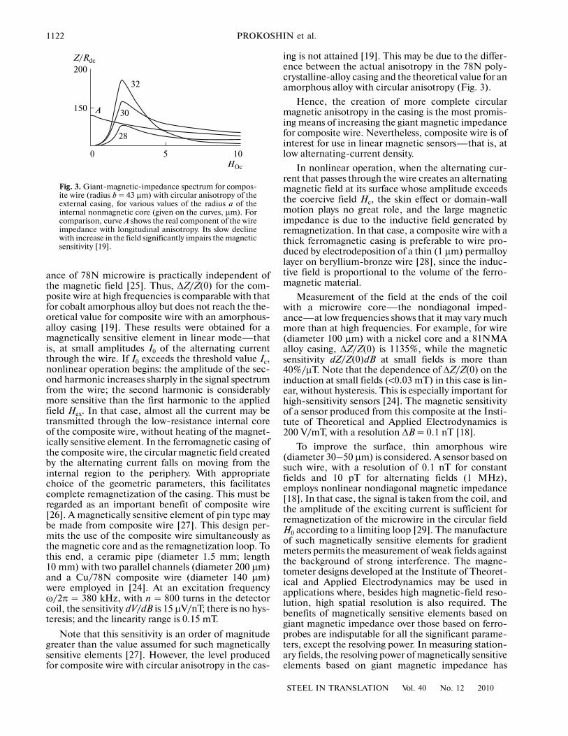
ing is not attained [19]. This may be due to the differ�ence between the actual anisotropy in the 78N poly�crystalline�alloy casing and the theoretical value for anamorphous alloy with circular anisotropy (Fig. 3).
Hence, the creation of more complete circularmagnetic anisotropy in the casing is the most promis�ing means of increasing the giant magnetic impedancefor composite wire. Nevertheless, composite wire is ofinterest for use in linear magnetic sensors—that is, atlow alternating�current density.
In nonlinear operation, when the alternating cur�rent that passes through the wire creates an alternatingmagnetic field at its surface whose amplitude exceedsthe coercive field Hc, the skin effect or domain�wallmotion plays no great role, and the large magneticimpedance is due to the inductive field generated byremagnetization. In that case, a composite wire with athick ferromagnetic casing is preferable to wire pro�duced by electrodeposition of a thin (1 μm) permalloylayer on beryllium�bronze wire [28], since the induc�tive field is proportional to the volume of the ferro�magnetic material.
Measurement of the field at the ends of the coilwith a microwire core—the nondiagonal imped�ance—at low frequencies shows that it may vary muchmore than at high frequencies. For example, for wire(diameter 100 μm) with a nickel core and a 81NMAalloy casing, ΔZ/Z(0) is 1135%, while the magneticsensitivity dZ/Z(0)dB at small fields is more than40%/μT. Note that the dependence of ΔZ/Z(0) on theinduction at small fields (<0.03 mT) in this case is lin�ear, without hysteresis. This is especially important forhigh�sensitivity sensors [24]. The magnetic sensitivityof a sensor produced from this composite at the Insti�tute of Theoretical and Applied Electrodynamics is200 V/mT, with a resolution ΔB = 0.1 nT [18].
To improve the surface, thin amorphous wire(diameter 30–50 μm) is considered. A sensor based onsuch wire, with a resolution of 0.1 nT for constantfields and 10 pT for alternating fields (1 MHz),employs nonlinear nondiagonal magnetic impedance[18]. In that case, the signal is taken from the coil, andthe amplitude of the exciting current is sufficient forremagnetization of the microwire in the circular fieldH0 according to a limiting loop [29]. The manufactureof such magnetically sensitive elements for gradientmeters permits the measurement of weak fields againstthe background of strong interference. The magne�tometer designs developed at the Institute of Theoret�ical and Applied Electrodynamics may be used inapplications where, besides high magnetic�field reso�lution, high spatial resolution is also required. Thebenefits of magnetically sensitive elements based ongiant magnetic impedance over those based on ferro�probes are indisputable for all the significant parame�ters, except the resolving power. In measuring station�ary fields, the resolving power of magnetically sensitiveelements based on giant magnetic impedance has
200
150
0 5 10HOc
Z/Rdc
32
30
28
A
Fig. 3. Giant�magnetic�impedance spectrum for compos�ite wire (radius b = 43 μm) with circular anisotropy of theexternal casing, for various values of the radius a of theinternal nonmagnetic core (given on the curves, μm). Forcomparison, curve A shows the real component of the wireimpedance with longitudinal anisotropy. Its slow declinewith increase in the field significantly impairs the magneticsensitivity [19].
STEEL IN TRANSLATION Vol. 40 No. 12 2010
MAGNETICALLY SENSITIVE PRECISION�ALLOY COMPONENTS 1123
improved from 10–8 to 10–10 T within 15 years, and thisis obviously not the limit. By contrast, the resolvingpower of ferroprobes has not significantly changed. Atpresent, magnetically sensitive elements based ongiant magnetic impedance are the first choice in fieldssuch as manufacturing (in particular, the measure�ment of the angle of rotation of control systems forvarious mechanisms, torque measurement, contact�less current measurement, monitoring of motor oper�ation at high temperatures, and control of vehiclemotion) [30]. The introduction of such sensitive ele�ments in defense systems, robot engineering, medi�cine, and biology within resonant sensors may beexpected in the near future [6]. These examples do notdemand the limiting resolving power of magneticallysensitive elements based on giant magnetic imped�ance. The basic benefits of such elements includecompactness, low cost, high speed, and temperaturestability. These properties ensure steady demand invarious fields. The combination of such sensitive ele�ments with transponders for surface active waves is ofparticular importance. Such designs permit wirelesssupply to the magnetically sensitive element and col�lection of its signal in radio channels [31]. This consid�erably expands the applicability of sensors with mag�netically sensitive elements based on giant magneticimpedance. For example, they may be useful in bordersecurity and in monitoring remote objects.
Obviously, the resolving power of magnetically sen�sitive elements based on giant magnetic impedancemay be further improved by reducing the intrinsicnoise of the microwire. The creation of such elementswith sensitivity in the picotesla (pT) range is a realisticprospect, according to the estimates in [18]. Thisentails theoretical and experimental study of the phys�ics of remagnetization and the development of manu�facturing technologies for limitingly uniform microw�ire with the minimum number of metastable states inthe magnetic system.
REFERENCES
1. Tumanski, S., Induction Coil Sensors: A Review, Meas.Sci. Technol., 2007, vol. 18, no. 3, pp. R31–R46.
2. Phan, M.H. and Peng, H.X., Giant Magnetoimped�ance Materials: Fundamentals and Applications, Prog.Mater. Sci., 2008, vol. 53, pp. 323–420.
3. http://isr.lviv.ua.4. www.telapat_defenced.com/shuman.htm.5. Baranochnikov, M.L., Mikromagnitoelectronika:
Ser. Uchebnik (Micromagnetoelectronics: TextbookSeries), Mordkovich, V.N., Ed., Moscow: DMK Press,2001, vol. 1.
6. Herrera�May, A.L., Aguilera�Cortes, L.A., Garcia�Ramirez, P.J., and Manjarrez, E., Resonant MagneticField Sensors Based on MEMS Technology, Sensors,2009, vol. 9, pp. 7785–7813.
7. Ripka, P., Review of Fluxgate Sensors, Sens. Actuators A,vol. 33, pp. 129–141, 1992.
8. Panina, L.V., Mohri, K., Uchiayma, T., and Noda, M.,Giant Magnetoimpedance in Co�Rich AmorphousWires and Films, IEEE Trans. Magn., 1995, vol. 31,pp. 1249–1260.
9. Harrison, E.P., Turney, G.L., Rowe, H., and Gollop, H.,The Electrical Properties of High Permeability WiresCarrying Alternating Current, Proc. Roy. Soc., 1936,vol. 157, pp. 451–479.
10. Gorelik, G.S., Transverse Magnetic Permeability, Dokl.Akad. Nauk SSSR, 1944, vol. 43, no. 5, pp. 204–206.
11. Popova, V.P., Galvanomagnetic and GalvanoelasticEffects in Ferronickel Alloys, Pretsizionnye splavy:sb. trudov TsNIIchermet, 1968, issue 54, pp. 55–60.
12. Makhotkin, V.E., Shurukhin, D.P., Lopatin, V.A.,et al., Magnetic Field Sensors Based on AmorphousRibbons, Sens. Actuators A, 1991, vol. 25–27, pp. 759–762.
13. Antonov, A.S., Gadetskii, S.N., Granovskii, A.B.,et al., Giant Magnetic Impedance in Amorphous andNanocrystalline Multilayer Structures, FMM, 1997,no. 6, pp. 60–71.
14. Ulitovsky, A.V., Maianski, I.M., and Avramenco, A.I.,USSR Patent 128427, Bulletin, 1960, no. 10, p. 14.
15. Ohnaka, I., Fukusaco, T., and Matui, T., Preparation ofAmorphous Wires, J. Japan. Inst. Met., 1981, vol. 45,pp. 751–762.
16. Rudkowski, P., Rudkowska, G., and Strom�Olsen, J.O.,The Fabrication of Fine Metallic Fibers by ContinuousMelt Extraction and Their Magnetic and MechanicalProperties, Mat. Sci. Eng., 1991, vol. A133, pp. 158–161.
17. Usov, N.A., Micromagnetism of Small FerromagneticParticles, Nanostructures, and Amorphous Wires,Extended Abstract of Doctoral Dissertation, Moscow,2001.
18. Antonov, A.S., Magnetic Impedance of FerromagneticMicrowires, Thin Films, and Multilayer Structures atHigh Frequency, Method of Continuous Casting ofGlass Coated Microwire, Extended Abstract of DoctoralDissertation, Moscow, 2003.
19. Usov, N., Antonov, A., and Granovsky, A., Theory ofGiant Magnetoimpedance Effect in Composite Amor�phous Wire, J. Magn. Magn. Mater., 1997, vol. 171,pp. 64–68.
20. Antonov, A.S., Granovskii, A.B., Kraposhin, V.S.,et al., Russian Patent 2155647, Byull. Izobret., 2000,no. 25.
21. Borisov, V.T., Prokoshin, A.F., Borisov, O.V., et al.,Thermophysical Model of Amorphous�Fiber Forma�tion at the Edge of a Disk, Stal’, 2003, no. 8, pp. 77–80.
22. Prokoshin, A.F., Kozlov, A.G., Krotov, A.P., et al., Rus�sian Patent 2075758, Byull. Izobret., 1997, no. 8.
23. Pretsizionnye splavy: sprav. izd. (Precision Alloys:A Handbook), Molotilov, B.V., Ed., Moscow: Metal�lurgiya, 1983, 2nd ed.
24. Prokoshin, A.F., Zakharov, E.K., Kuznetsov, V.V.,et al., Composite Wire Materials with Giant MagneticImpedance, Probl. Chern. Metall. Materialov., 2008,no. 1, pp. 76–80.
25. Antonov, A.S., Rakhmanov, A.L., Buznikov, N.A.,et al., Magnetic Properties and Magneto�Impedance of
1124
STEEL IN TRANSLATION Vol. 40 No. 12 2010
PROKOSHIN et al.
Cold�Drawn Permalloy–Copper Composite Wires,IEEE Trans. Magn., 1999, vol. 35, no. 5(II), pp. 364–366.
26. Antonov, A.S., Buznikov, N.A., Prokoshin, A.F., et al.,Nonlinear Remagnetization of Composite Copper–Permalloy Wires Induced by High�Frequency Current,Pis’ma ZhTF, 2001, vol. 27, issue 8, pp. 12–18.
27. Afanas’ev, Yu.V., Ferrozondy (Ferroprobes), Leningrad:Energiya, 1969.
28. Beach, R.S., Smith, N., Platt, C.L., et al., Magneto�Impedance Effect in NiFe Plated Wire, Appl. Phys.Lett., 1996, vol. 68, p. 2753–2755.
29. Antonov, A.S., Buznikov, N.A., Granovsky, A.B., et al.,Nonlinear Magnetoimpedance Effect in Soft MagneticAmorphous Wires Extracted from Melt, Sens. Actuators A,2003, vol. 106, pp. 208–211.
30. http://www.aichi�mi.com.
31. Hauser, H., Steindl, R., Hausleitner, C., et al., Wire�lessly Interrogable Magnetic Field Sensor UtilizingGiant Magneto�Impedance Effect and Surface Acous�tic Wave Device, IEEE Instrum. Meas. Mag., 2000,vol. 49, pp. 648–652.