mafh - hydac-na.com€¦ · user manual mafh l-2999 hydac ... since the air flow rate of the hydac...
TRANSCRIPT
L-2999
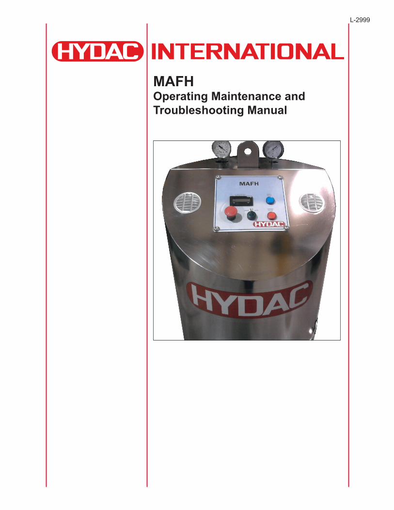
MAFH Operating Maintenance and Troubleshooting Manual

L-2999 | Created 9.2012
User Manual MAFH L-2999
HYDAC En TOC
- TABLE OF CONTENTS-
1. Introduction ………………………………………………………………………………………………………………………... 4 2. Warnings, Cautions and Notes ………………………………………………………………………………………………… 53. Specifications ……………………………………………………………………………………………………………………... 74. Components ……………………………………………………………………………………………………………………….. 85. Operating Instructions …………………………………………………………………………………………………………... 11 5.1 Percent Saturation Water in Oil Display …………………………………………………………………………………….. 11 5.2 Fluid Oscillation in Auto Mode ……………………………………………………………………………………………….. 11 5.3 Drain Mode …………………………………………………………………………………………………………………….. 116. Maintenance Instructions ……………………………………………………………………………………………………….. 12 6.1 Servicing Filter Elements ……………………………………………………………………………………………………... 12 6.2 Servicing Air Breathers ……………………………………………………………………………………………………….. 12 6.3 AC Motors ……………………………………………………………………………………………………………………… 12 6.4 Replacement Parts ……………………………………………………………………………………………………………. 127. Warranty ……………………………………………………………………………………………………………………………. 13 Appendix 1A - Hydraulic Schematic ………………………………………………………………………………………….. 14 Appendix 2A - Electrical Schematic …………………………………………………………………………………………... 15 Appendix 3A - Troubleshooting ……………………………………………………………………………………………….. 17 Appendix 4A - Frequently Asked Questions ………………………………………………………………………………… 18
L-2999 MAFH User Manual
4 En HYDAC
1. INTRODUCTION
HYDAC’spatentpendingdewateringunit(MAFH)isthefirstofitskindonthemarket.TheMAFHoffers fullyautomateddewateringofhydraulicfluidsandavarietyofotherpetroleumbasedfluids.
TheoperatingprincipleoftheMAFHdiffersfromexistingdewateringmethods.TheMAFHisapositivepressuresystemthat uses100%masstransfertoremovewaterfromtheoperatingfluid.Roomairisheatedusingaproprietarymethodto improvetheabilityoftheairtoabsorbwatervapor.Thisheatedairisthendistributedupwardsinthereactionchamber throughcascadingdropletsofoperatingfluid.Theheatedairstreamremovesfree,emulsified,&dissolvedwaterandsome dissolved gases.
Inmosttraditionalindustrialvacuumdehydrators,masstransferisalsothemeanstodewater.Amild/mediumvacuum expandstheroomairandproportionatelyreducestherelativehumidityoftheair.Theairflowislimitedtothedisplacement ofthevacuumpump.Higherefficiencyvacuumunitsuseaclosedcycletosealoperatingfluidwithhighheatandhigh vacuumtoboiloffwater.Theseunitshavehighefficiencybuthavelowflowratesandcanpotentiallydamagetheoperating fluidovertime.
SincetheairflowrateoftheHYDACMAFHisnotlimitedbyvacuumpumpdisplacement,itismoreeffectiveindewatering operatingfluidsundersimilarconditionsandflowratesthantheabovetechnologies.Inaddition,theMAFHdoesnothave theinitialandmaintenanceeconomicdisadvantagesofavacuumpumpbasedsystem.
TheMAFHusesaregenerativeairinjectionsystemtoheatanddistributeroomairintothereactionchamber.Theoptional compressedairsystemusesanavailabledried,cleanairsource.Anyresidualfluidmistismechanicallyseparatedfromthe moistairstreambeforeitisventedfromthechamber.Thesystemfluidiscycledthroughthereactionchamberviaasystem includingavanepump,twovalves,andthreefilters.Duringthefirstcycle,fluidispumpedandgentlysprayedontopof theloose,reticulatedmediauntilthefluidlevelinthesumptriggersthehighfloatswitch.Thefluidisthenpumpedfromthe pump and returned to the customer.
TheMAFHiscontrolledbyacontrolsystemwhichmonitorssystemfunctionandcontrolsthecycleoperation.Anon-board watersensor(AS1000)monitorstherelativehumidityoftheoperatingfluidanddisplaystheactualhumidityvalueatthe control panel.
User Manual MAFH L-2999
HYDAC En 5
WARNING!BEFORE RUNNING THIS MAFH-A,
THE OPERATOR MUST READ AND UNDERSTANDTHE CONTENTS OF THIS MANUAL!
THE MAFH-A MUST REMAIN IN AN UPRIGHT POSITION AT ALL TIMES. IF THE UNIT IS TIPPED MORE THAN 15 DEGREES OR IS KNOCKED OVER CONTACT HYDAC IMMEDIATELY. DO NOT
ATTEMPT TO OPERATE THE UNIT IF IT HAS BEEN TIPPED OVER OR DROPPED.
HIGHLY AERATED OIL WITH EXCESSIVE FOAM MAY CAUSE THE FLOAT SWITCHES INTERNAL TO THE FLUID CHAMBER
TO MALFUNCTION. IF THE OIL IS AERATED ALLOW THE FLUID TO SETTLE AND THE AIR TO DISSIPATE PRIOR TO RUNNING IT
THROUGH THE MAFH-A.
L-2999 MAFH User Manual
6 En HYDAC
2. WARNINGS, CAUTIONS AND NOTES
Recognize Safety Information Thisisthesafetyalertsymbol.Whenyouseethissymbolonyourmachineorinthismanual,bealert forthepotentialofpersonalinjury.Followtheprecautionsandsafeoperatingpracticeshighlightedbythissymbol. Asignalword—DANGER,WARNING,orCAUTION—usedwiththesafetyalertsymbol.DANGERidentifiesthe mostserioushazards.GeneralprecautionsareonCAUTIONlabels.
Follow Safety Instructions Readthesafetymessagesinthismanualandonthemachine.Followthesewarningsandinstructionscarefully. Reviewthemfrequently.Besurealloperatorsofthismachineunderstandeverysafetymessage.Replacesafety labelsimmediatelyifmissingordamaged.
Operate Only If Qualified Donotoperatethismachineunlessyouhavereadtheoperator’smanualcarefullyandyouhavebeenqualifiedby supervisedtrainingandinstruction.Familiarizeyourselfwiththejobsiteandyoursurroundingsbeforeoperating.
Inspect Machine Inspecttheequipmentcarefullybeforeeachuse.Keepallpartsingoodconditionandproperlyinstalled.Fix damageandreplacewornorbrokenpartsimmediately.Payspecialattentiontohydraulichosesandelectrical power cord.
Handle Fluids Safely—Avoid Fires Filteringoffuelorotherflammableliquidsisnotrecommended.Storeflammablefluidsawayfromfirehazards.Do notincinerateorpuncturepressurizedcontainers.Makesuremachineiscleanoftrash,grease,anddebris.Donot storeoilyrags;theycanigniteandburnspontaneously.
Prepare for Emergencies Bepreparedifafirestarts.Keepafirstaidkitandfireextinguisherhandy.Keepemergencynumbersfordoctors, ambulanceservice,hospital,andfiredepartmentnearyourtelephone.
Practice Safe Maintenance Understandserviceprocedurebeforedoingwork.Workareashouldlevel,clean,anddry.Beforeservicing machine: -Positionmachineonalevelsurface -Allowtocoolifhot
Keepallpartsingoodconditionandproperlyinstalled.Fixdamageimmediately.Replacewornorbrokenparts. Removeanybuildupofgrease,oil,ordebris.
Handle Chemical Products Safely Directexposuretohazardouschemicalscancauseseriousinjury.Potentiallyhazardouschemicalsusedwith equipmentincludesuchitemsaslubricants,coolants,paints,andadhesives.AMaterialSafetyDataSheet (MSDS)providesspecificdetailsonchemicalproducts:physicalandhealthhazards,safetyprocedures,and\ emergencyresponsetechniques.ChecktheMSDSbeforeyoustartanyjobusingahazardouschemical.That wayyouwillknowexactlywhattherisksareandhowtodothejobsafely.Thenfollowproceduresand recommendedequipment.(ContactHYDACpriortousingwithfluidsotherthanhydraulicfluids).
Wear Protective Clothing Wearclosefittingclothingandsafetyequipmentappropriatetothejob.Operatingequipmentsafetyrequiresthe fullattentionoftheoperator.Donotwearradioormusicheadphoneswhileoperatingthemachine.
Service Machines Safely Tielonghairbehindyourhead.Donotwearanecktie,scarf,looseclothing,ornecklacewhenyouworknear machinetoolsormovingparts.Iftheseitemsweretogetcaught,severeinjurycouldresult.Removeringsand otherjewelrytopreventelectricalshortsandentanglementinmovingparts.
User Manual MAFH L-2999
HYDAC En 7
Illuminate Work Area Safely Illuminateyourworkareaadequatelybutsafely.Useaportablesafetylightforworkinginsideorunderthe machine.Makesurethebulbisenclosedbyawirecage.Thehotfilamentofanaccidentallybrokenbulbcanignite spilledfueloroil.
Work In Clean Area Beforestartingajob: -Cleanworkareaandmachine -Makesureyouhaveallnecessarytoolstodoyourjob. - Have the right parts on hand. - Read all instructions thoroughly; do not attempt shortcuts.
Use Proper Tools Usetoolsappropriatetothework.Makeshifttoolsandprocedurescancreatesafetyhazards.Forlooseningand tighteninghardware,usethecorrectsizetools.DONOTuseU.S.measurementtoolsonmetricfasteners.Avoid bodilyinjurycausedbyslippingwrenches.
Dispose of Waste Properly Improperlydisposingofwastecanthreatentheenvironmentandecology.Useleak-proofcontainerswhendraining fluids.Donotusefoodorbeveragecontainersthatmaymisleadsomeoneintodrinkingfromthem.Donotpour wasteontotheground,downadrain,orintoanywatersource.
3. Specifications
Average delivered Flow Rate: 1.5gpm(5.7L/min)Pump Flow Rate: 3gpm(11.4L/min)
Relief Pressure Setting: 100psi(6.9bar)Weight (Approx.): 295lbs(134kg)
Operating Temperature (Hydraulic):*Depending on Viscosity
40° F to 160° F(4° C to 71° C)
Operating Temperature (Electronic):*Depending on Viscosity
50° F to 113° F(10° C to 45° C)
Environmental Rating: Type2Power Requirements: 120 VAC 60 HZ @ 15 A
Fluid Compatibility: HydrocarbonBasedHydraulicFluids(Viton seals standard)
Viscosity: <1,000SUS
L-2999 MAFH User Manual
8 En HYDAC
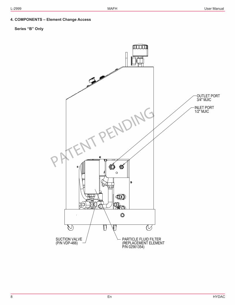
4. COMPONENTS – Element Change Access
Series “B” Only
PATENT PENDING
PARTICLE FLUID FILTER(REPLACEMENT ELEMENT P/N 02561354)
INLET PORT1/2" MJIC
OUTLET PORT3/4" MJIC
SUCTION VALVE(P/N VDP-466)
User Manual MAFH L-2999
HYDAC En 9
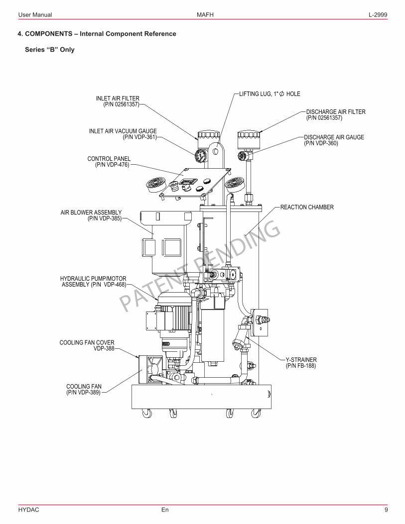
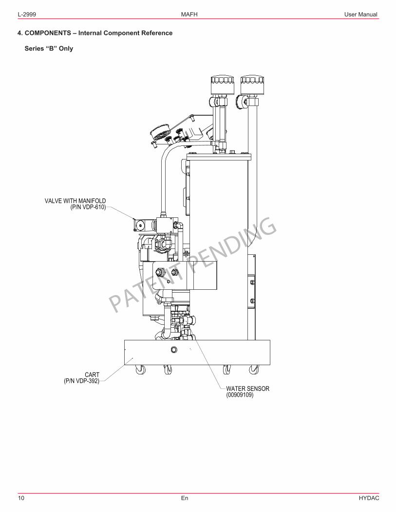
4. COMPONENTS – Internal Component Reference
Series “B” Only
PATENT PENDING
LIFTING LUG, 1" HOLE
REACTION CHAMBER
HYDRAULIC PUMP/MOTORASSEMBLY (P/N VDP-468)
AIR BLOWER ASSEMBLY(P/N VDP-385)
INLET AIR FILTER(P/N 02561357)
DISCHARGE AIR FILTER(P/N 02561357)
INLET AIR VACUUM GAUGE(P/N VDP-361)
CONTROL PANEL(P/N VDP-476)
COOLING FAN(P/N VDP-389)
COOLING FAN COVERVDP-388
DISCHARGE AIR GAUGE(P/N VDP-360)
Y-STRAINER(P/N FB-188)
L-2999 MAFH User Manual
10 En HYDAC
4. COMPONENTS – Internal Component Reference
Series “B” Only
PATENT PENDINGVALVE WITH MANIFOLD
(P/N VDP-610)
CART(P/N VDP-392)
WATER SENSOR(00909109)
User Manual MAFH L-2999
HYDAC En 11
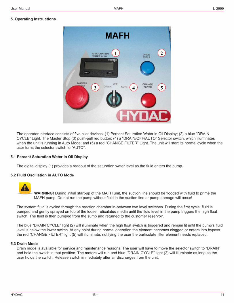
5. Operating Instructions
Theoperatorinterfaceconsistsoffivepilotdevices:(1)PercentSaturationWaterinOilDisplay;(2)ablue“DRAIN CYCLE”Light.TheMasterStop(3)push-pullredbutton;(4)a“DRAIN/OFF/AUTO”Selectorswitch,whichilluminates whentheunitisrunninginAutoMode;and(5)ared“CHANGEFILTER”Light.Theunitwillstartitsnormalcyclewhenthe userturnstheselectorswitchto“AUTO”.
5.1 Percent Saturation Water in Oil Display
Thedigitaldisplay(1)providesareadoutofthesaturationwaterlevelasthefluidentersthepump.
5.2 Fluid Oscillation in AUTO Mode
WARNING! Duringinitialstart-upoftheMAFHunit,thesuctionlineshouldbefloodedwithfluidtoprimethe MAFHpump.Donotrunthepumpwithoutfluidinthesuctionlineorpumpdamagewilloccur!
Thesystemfluidiscycledthroughthereactionchamberin-betweentwolevelswitches.Duringthefirstcycle,fluidis pumpedandgentlysprayedontopoftheloose,reticulatedmediauntilthefluidlevelinthepumptriggersthehighfloat switch.Thefluidisthenpumpedfromthesumpandreturnedtothecustomerreservoir.
Theblue“DRAINCYCLE”light(2)willilluminatewhenthehighfloatswitchistriggeredandremainlituntilthepump’sfluid levelisbelowthelowerswitch.Atanypointduringnormaloperationtheelementbecomescloggedorentersintobypass thered“CHANGEFILTER”light(5)willilluminate,notifyingtheusertheparticulatefilterelementneedsreplaced.
5.3 Drain Mode Drainmodeisavailableforserviceandmaintenancereasons.Theuserwillhavetomovetheselectorswitchto“DRAIN” andholdtheswitchinthatposition.Themotorswillrunandblue“DRAINCYCLE”light(2)willilluminateaslongasthe userholdstheswitch.Releaseswitchimmediatelyafterairdischargesfromtheunit.
L-2999 MAFH User Manual
12 En HYDAC
6. Maintenance Instructions
Nomaintenanceoperationsshouldbecarriedoutwhiletheunitisrunning.Beforestartinganyothermaintenance operations,ensurethatthesystemisshutdownandelectricallyisolated.
6.1 Servicing Filter Elements
Donotrunthesystemwithoutafilterelementinstalled.Useonlyspecifiedreplacementfilterelements.Accesstothe(3) fluidfilterelementsarethroughtheloweraccesspanel.Seesection4forexactlocation
6.2 Servicing the Air Breathers Theairbreathersaresimplyhandtightened.Usedbreathersmayrequireawrenchtoremove.The(2)airbreathersused are identical.
6.3 AC Motors
■Themotorshouldbeinspectedatregularintervals(every500hoursofoperationorevery3months,whicheveroccurs first).Keepthemotorcleanandtheventilationopeningsclear. ■Duringoperation,listenforunusualnoises,especiallyintheareasaroundthebearings.Rumblingorrubbingnoises couldbesignsofinternaldamage.
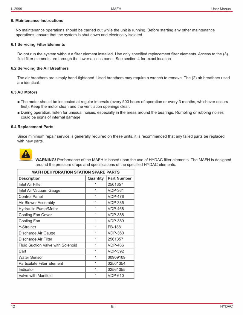
6.4 Replacement Parts
Sinceminimumrepairserviceisgenerallyrequiredontheseunits,itisrecommendedthatanyfailedpartsbereplaced with new parts.
WARNING!PerformanceoftheMAFHisbasedupontheuseofHYDACfilterelements.TheMAFHisdesigned aroundthepressuredropsandspecificationsofthespecifiedHYDACelements.
MAFH DEHYDRATION STATION SPARE PARTS Description Quantity Part Number Inlet Air Filter 1 2561357Inlet Air Vacuum Gauge 1 VDP-361 Control Panel 1 VDP-476 AirBlowerAssembly 1 VDP-385 HydraulicPump/Motor 1 VDP-468 Cooling Fan Cover 1 VDP-388 Cooling Fan 1 VDP-389 Y-Strainer 1 FB-188 Discharge Air Gauge 1 VDP-360 Discharge Air Filter 1 2561357Fluid Suction Valve with Solenoid 1 VDP-466Cart 1 VDP-392 Water Sensor 1 00909109Particulate Filter Element 1 02561354Indicator 1 02561355ValvewithManifold 1 VDP-610
User Manual MAFH L-2999
HYDAC En 13
7. WARRANTY
Warranty,LimitationofLiabilityandRemedies: THEREISNOWARRANTYOFMERCHANTABILITYORFITNESSFORANYPARTICULARPURPOSEWITHRESPECT TOANYOFTHEPRODUCTS,NORISTHEREANYOTHERWARRANTYEXPRESSORIMPLIED,EXCEPTAS PROVIDED FOR HEREIN.
ForaperiodoftwelvemonthsfromthedateofdeliveryfromSellerorthreethousandhoursofuse,whicheveroccursfirst (the“WarrantyPeriod”,SellerwarrantsthatproductsmanufacturedbySellerwhenproperlyinstalledandmaintained,and operatedatratings,specificationsanddesignconditions,willbefreefromdefectsinmaterialandworkmanship.Byway ofexplanationandnotlimitation,theSellerdoesnotwarranttheservicelifeofthefilterelementsasthisisbeyondthe Seller’scontrolanddependsupontheconditionofthesystemintowhichthefilterisinstalled.
Seller’sliabilityunderanywarrantyislimitedsolely(inSeller’sdiscretion)toreplacing(FOBoriginalshippoint),repairing orissuingcreditforproductsthatbecomedefectiveduringtheWarrantyPeriod.PurchasershallnotifySellerpromptly inwritingofanyclaimsandprovideSellerwithanopportunitytoinspectandtesttheproductclaimedtobedefective. BuyershallprovideSellerwithacopyoftheoriginalinvoicefortheproduct,andprepayallfreightchargestoreturnany productstoSeller’sfactory,orotherfacilitydesignatedbySeller.Allclaimsmustbeaccompaniedbyfullparticulars, includingsystemoperatingconditions,ifapplicable.
SellershallnotbeliableforanyproductalteredoutsideoftheSeller’sfactoryexceptbySellerorSeller’sauthorized distributor,andthen,astothelatter,onlyforproductswhichhavebeenassembledbythedistributorinaccordance withSeller’swritteninstructions.NorshallSellerbeliableforaproductsubjectedtomisuse,abuse,improperinstallation, application,operation,maintenanceorrepair,alteration,accidentornegligenceinuse,storagetransportationorhandling.
InnoeventwillSellerbeliableforanydamages,incidental,consequentialorotherwise,whetherarisingoutoforin connectionwiththemanufacture,packaging,delivery,storage,use,misuse,ornonuseofanyofitsproductsoranyother cause whatsoever.
Service ShippingAddressforRecalibrationandRepairWork
HYDAC LLC 580WestParkRoad Leetsdale,PA15056
L-2999 MAFH User Manual
14 En HYDAC
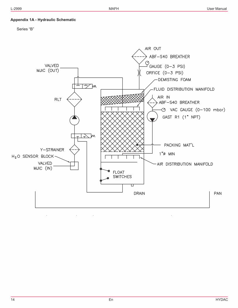
Appendix 1A - Hydraulic Schematic Series“B”
User Manual MAFH L-2999
HYDAC En 15
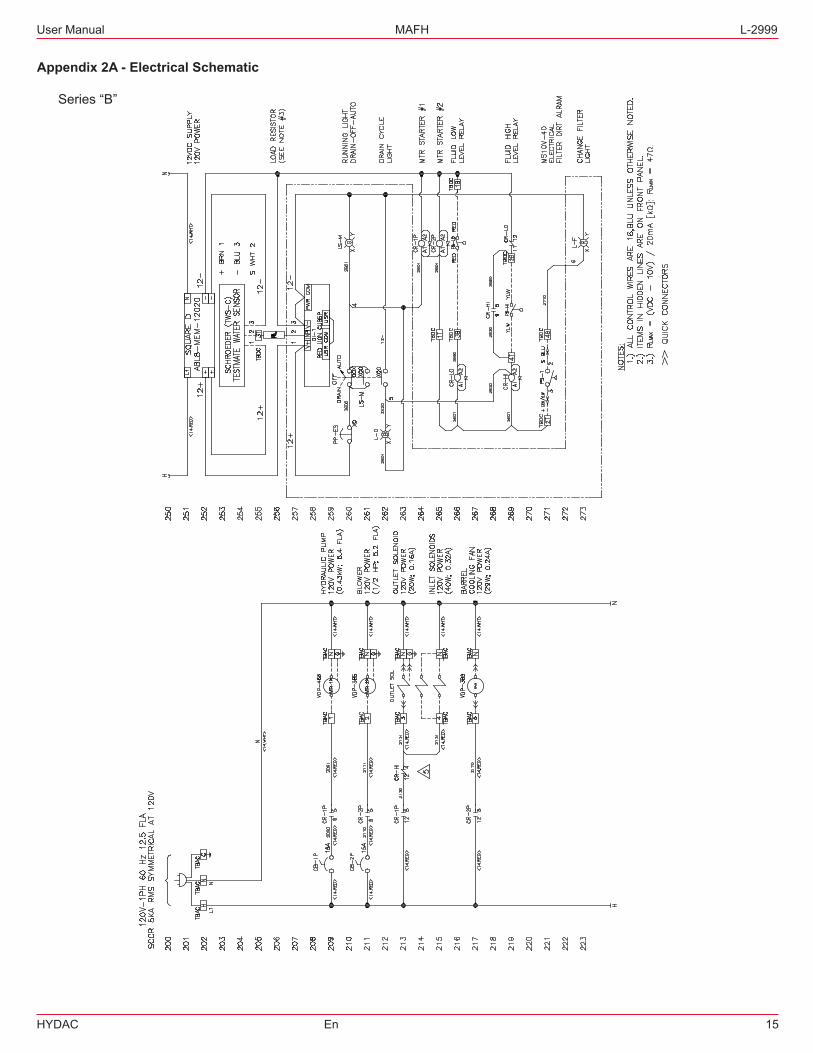
Appendix 2A - Electrical Schematic Series“B”
L-2999 MAFH User Manual
16 En HYDAC
User Manual MAFH L-2999
HYDAC En 17
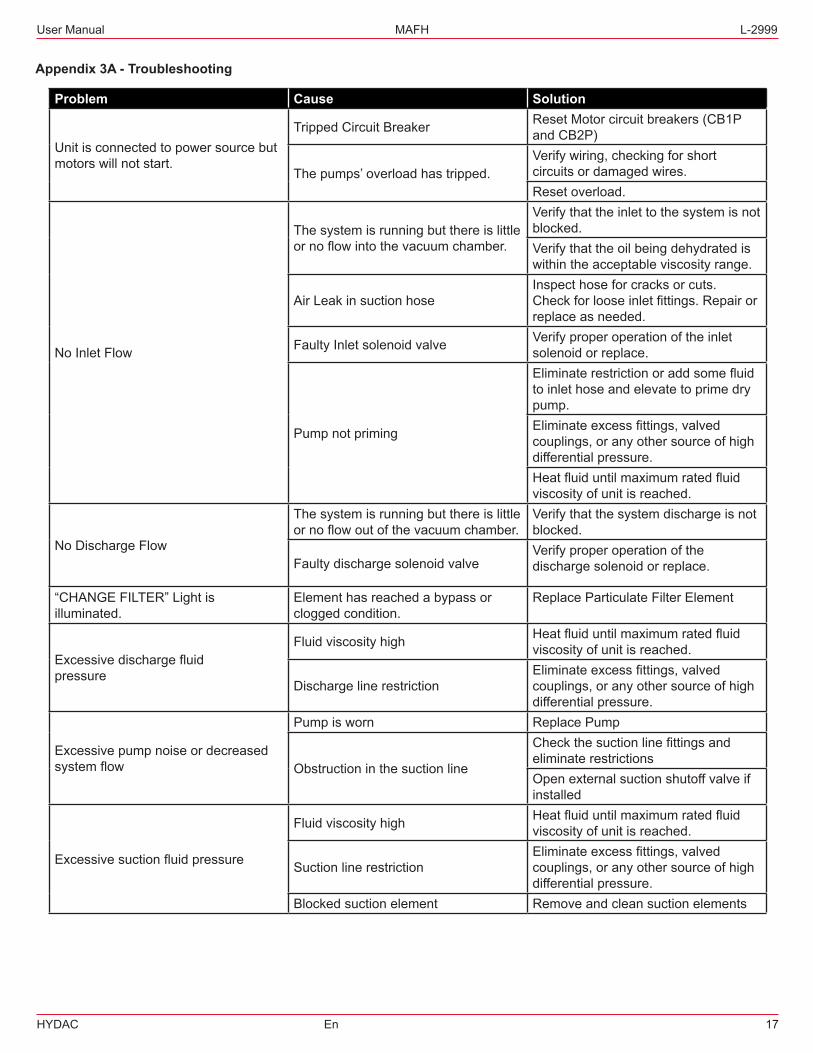
Appendix 3A - Troubleshooting
Problem Cause Solution
Unitisconnectedtopowersourcebutmotors will not start.
TrippedCircuitBreaker ResetMotorcircuitbreakers(CB1Pand CB2P)
Thepumps’overloadhastripped.Verifywiring,checkingforshortcircuits or damaged wires.Reset overload.
No Inlet Flow
Thesystemisrunningbutthereislittleornoflowintothevacuumchamber.
Verifythattheinlettothesystemisnotblocked.Verifythattheoilbeingdehydratediswithintheacceptableviscosityrange.
AirLeakinsuctionhoseInspecthoseforcracksorcuts.Checkforlooseinletfittings.Repairorreplace as needed.
Faulty Inlet solenoid valve Verifyproperoperationoftheinletsolenoid or replace.
Pump not priming
Eliminaterestrictionoraddsomefluidto inlet hose and elevate to prime dry pump.Eliminateexcessfittings,valvedcouplings,oranyothersourceofhighdifferentialpressure.Heatfluiduntilmaximumratedfluidviscosityofunitisreached.
No Discharge Flow
Thesystemisrunningbutthereislittleornoflowoutofthevacuumchamber.
Verifythatthesystemdischargeisnotblocked.
Faulty discharge solenoid valveVerifyproperoperationofthedischarge solenoid or replace.
“CHANGEFILTER”Lightisilluminated.
Elementhasreachedabypassorclogged condition.
Replace Particulate Filter Element
Excessivedischargefluidpressure
Fluid viscosity high Heatfluiduntilmaximumratedfluidviscosityofunitisreached.
Discharge line restrictionEliminateexcessfittings,valvedcouplings,oranyothersourceofhighdifferentialpressure.
Excessivepumpnoiseordecreasedsystemflow
Pump is worn Replace Pump
Obstructioninthesuctionline
Checkthesuctionlinefittingsandeliminate restrictionsOpenexternalsuctionshutoffvalveifinstalled
Excessivesuctionfluidpressure
Fluid viscosity high Heatfluiduntilmaximumratedfluidviscosityofunitisreached.
Suction line restrictionEliminateexcessfittings,valvedcouplings,oranyothersourceofhighdifferentialpressure.
Blockedsuctionelement Remove and clean suction elements
L-2999 MAFH User Manual
18 En HYDAC
Appendix 4A - Frequently Asked Questions
1. Remote monitoring. Do we have any spare dry contacts that customer can tie into for remote monitoring? Therearenospareterminalblocksonthepanel.Therearecontactsopenonthecontrolrelaywhichcontrolstheflow inandoutofthemachine(SameastheBlueDrainLight).
2. Units will be located in an engine room. Issue is ambient temperature. What are the minimum and maximum ambient temperatures? Theoverallcontrolwilloperatewith-13thru131°F(-25–55°C).
3. What is the power consumption without blower? At120VACthefullloadcurrentwouldbe8Amps.
4. What is the minimum and maximum viscosity of the fluids that can be used with the DEHYDRATION STATION™? Theminimumviscosityis70SUSandthemaximumviscosityis1000SUS.
5. What is the dewatering rate for the DEHYDRATION STATION™? Thedewateringrateisshowninthespecificationssection
6. What is the size and weight of the DEHYDRATION STATION™? Thediameteroftheunitisthesameasa55gallondrumallowingtheDEHYDRATIONSTATION™tofitintosmall spaces.Theactualdimensionsare46”highby23.25”outerdiameterandtheweightis295lbs.
7. Where is the best place the install the unit? How far should it be from the system? Thebestplacetoinstalltheunitisasclosetothereservoiraspossible.Therecommendedmaximumoperating distanceis15feet.
8. What is the size of the filter hose I should use? TheOutletPortis¾inchMJICandtheInletPortis½inchMJIC.
9. Is there an explosion proof version available? TheDEHYDRATIONSTATION™isavailablewithanexplosionproofversionmeetingClass1,Division2ratings.
10. What readings will I get from the water sensor? Theon-boardWaterSensorwillmonitorstherelativehumidityoftheoperatingfluidandwilldisplaytheactual% saturationofwaterintheoilinreal-time.
11. What fluids can I use with the DEHYDRATION STATION™? TheDEHYDRATIONSTATION™isrecommendedforusewithhydraulicfluidsandotherpetroleumbasedfluids.
12. What is the cycle time? Thecycletimeis30seconds.
13. When do the breather elements get changed? Thebreatherelementsaretobechangedasthepressureincreasesonthegaugesbeloweachbreather.
14. Who do I contact for pricing and availability or if I need additional technical assistance? CustomerServicewillbehappytoprovideyouwithpricingandavailability.PleasecontactyourProductManagerfor anytechnicalquestionsorifyouneedadditionalinformationontheDEHYDRATIONSTATION™.
Internet: www.hydac.comE-Mail:[email protected]