madhya pradesh jal nigam maryadit pradesh jal nigam maryadit (a govt.of m.p. undertaking) tender...
TRANSCRIPT
MADHYA PRADESH JAL NIGAM MARYADIT (A GOVT.OF M.P. UNDERTAKING)
TENDER
DOCUMENTON
FORM- ‘F’ FOR
LUMP– SUM
CONTRACT FOR
Engineering, procurement, construction, testing, commissioning, trial run and operation &
maintenance of various components of "Satna - Bansagar Multi Village Rural Water Supply
Scheme, Distt. Satna" for ultimate capacity of bringing 166.00 mld treated water (23 hours of
pumping) from the Bansagar Dam on river Sone to 1019 villages of Maihar, Unchehra, Rampur
Baghelan, Amarpatan and Ramnagar Blocks of Distric Satna in Single Package on ‘Turn-key job
basis’ including trial run and running & maintenance of the entire scheme for 10 years. (Cost of
running and maintenance will be paid separately)
NIT No. 23/PROC/NDB/MPJNM/2018-19, Dated: 17.05.2018
Probable Amount of Contract: INR 124527.6 lacs
Earnest Money Deposit: INR 50.00 lacs
Date of Pre-Bid Meeting: 01/06/2018
MANAGING DIRECTOR
MADHYAPRADESH JAL NIGAM MARYADIT
2nd FLOOR, D-WING, VINDHYACHAL BHAWAN
BHOPAL-462004 (M.P)
MADHYA PRADESH JAL NIGAM MARYADIT
(A GOVT. OF M.P. UNDERTAKING)
OFFICE OF THE MANAGING DIRECTOR
M.P. JAL NIGAM MARYADIT, BHOPAL
TENDER DOCUMENT
FOR LUMP-SUM CONTRACT
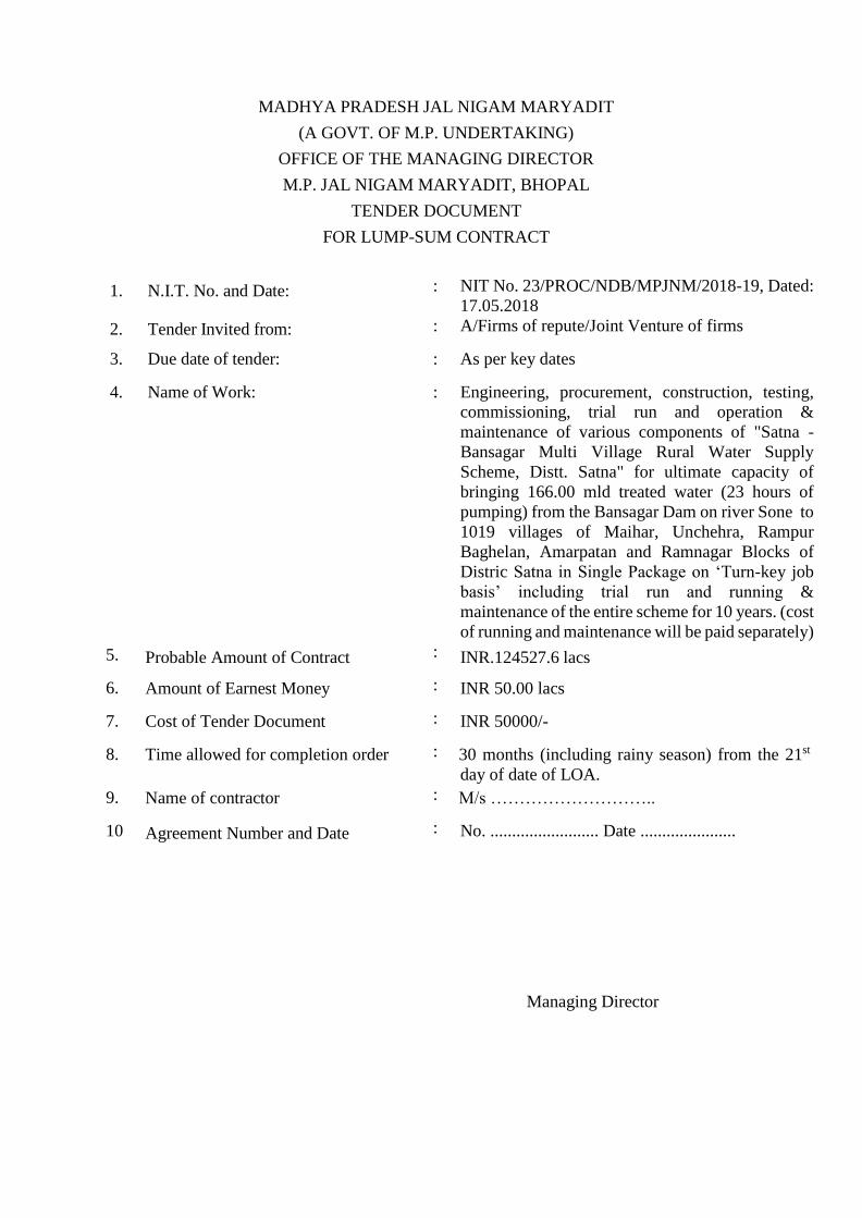
1. N.I.T. No. and Date: : NIT No. 23/PROC/NDB/MPJNM/2018-19, Dated:
17.05.2018
2. Tender Invited from: : A/Firms of repute/Joint Venture of firms
3. Due date of tender: : As per key dates
4. Name of Work: : Engineering, procurement, construction, testing,
commissioning, trial run and operation &
maintenance of various components of "Satna -
Bansagar Multi Village Rural Water Supply
Scheme, Distt. Satna" for ultimate capacity of
bringing 166.00 mld treated water (23 hours of
pumping) from the Bansagar Dam on river Sone to
1019 villages of Maihar, Unchehra, Rampur
Baghelan, Amarpatan and Ramnagar Blocks of
Distric Satna in Single Package on ‘Turn-key job
basis’ including trial run and running &
maintenance of the entire scheme for 10 years. (cost
of running and maintenance will be paid separately)
5. Probable Amount of Contract : INR.124527.6 lacs
6. Amount of Earnest Money : INR 50.00 lacs
7. Cost of Tender Document : INR 50000/-
8. Time allowed for completion order : 30 months (including rainy season) from the 21st
day of date of LOA.
9. Name of contractor : M/s ………………………..
10 Agreement Number and Date : No. ......................... Date ......................
Managing Director

MADHYA PRADESH JAL NIGAM MARYADIT
(A GOVT. OF M.P. UNDERTAKING)
INDEX
S. No. Particulars Page No.
1 Essential and Non-negotiable Instructions for the Tenderers 5
2 Tender notice 13
3 Detailed notice inviting tender 22
4 Tender for Lump-sum Contract 56
5 Conditions of the Contract 57
6 Annexure –1: Joint Venture/ Consortium Requirements 63
7 Annexure –2: Affidavit 65
8 Annexure- ‘A’: Model rules for labour camp 67
9 Annexure- ‘B’: Contract labour regulations 69
10 Annexure- ‘D’: Form of Income Tax clearance certificate 70
11 Annexure- ‘E’: Brief Specifications and scope of work for
following works-
71
Chapter 1.1: Intake well – cum – pump house 88
Chapter 1.2: Raw water pumping main 99
Chapter 1.3: Clear water pumping main 114
Chapter 1.4: Clear water gravity main 114
Chapter 1.5 : Water Treatment Plant – cum – pump house 128
Chapter 1.6: OHT/OHSR/MBR/ESR)/Sump cum Pump house 175
Chapter 1.7: Distribution Network 186
Chapter 1.8: Raw and Clear water Pumping Equipments 213
Chapter 1.9: Electrification of electric power line connection at
Intake well, WTP & IPS
225
Chapter 1.10: Approach road, Boundary wall and Staff Quarters 230
Chapter 1.11: Automation at Intake, WTP, IPS, MBR's, and at
ESR's/GLR
233
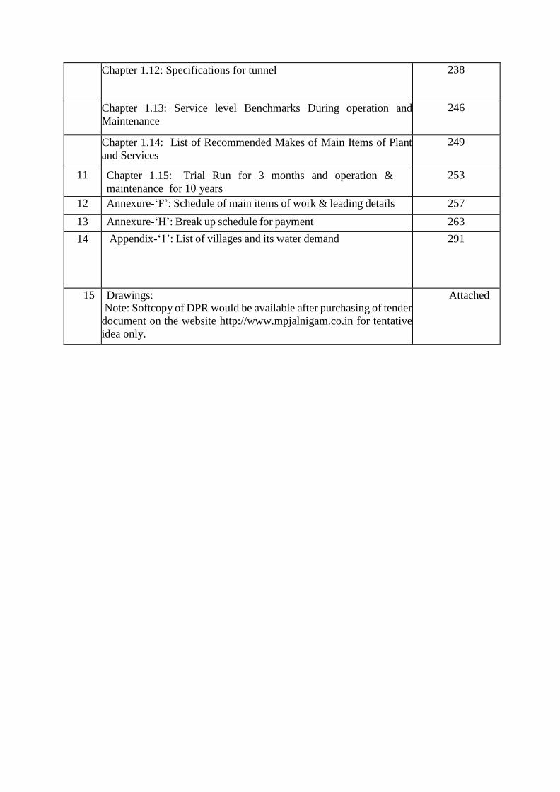
Chapter 1.12: Specifications for tunnel
238
Chapter 1.13: Service level Benchmarks During operation and
Maintenance
246
Chapter 1.14: List of Recommended Makes of Main Items of Plant
and Services
249
11 Chapter 1.15: Trial Run for 3 months and operation &
maintenance for 10 years
253
12 Annexure-‘F’: Schedule of main items of work & leading details 257
13 Annexure-‘H’: Break up schedule for payment 263
14 Appendix-‘1’: List of villages and its water demand 291
15 Drawings: Note: Softcopy of DPR would be available after purchasing of tender
document on the website http://www.mpjalnigam.co.in for tentative
idea only.
Attached

PART – I
Essential and Nonnegotiable Instructions for the Tenderers
1. No conditional tender shall be accepted under any circumstances whatsoever.
2. Price escalation shall be payable as per formula given in this Notice Inviting Tender
(hereinafter, NIT).
3. The tenderers shall ensure that their tenders are in conformity with the conditions
and clauses of this N.I.T. and the contract agreement form in general, and with
regard to security deposit, mode of payment for extra work, if any, completion time,
guarantee about mechanical and electrical equipment's & water tightness, tests, structure
stability etc. for entire Civil works in particular.
4. This tender is on turnkey job basis, hence no advance payment towards the mechanical
& electrical equipment's, items will be considered and no advance mobilization will be
allowed for any purpose.
5. Return of security deposit furnished by way of unconditional and irrevocable bank
guarantee shall be processed only in the manner and time prescribed in this N. I. T.
6. The tenderer/contractor shall get the gradients/ reduced levels verified on his own at his
own expenditure and responsibility. The Madhya Pradesh Jal Nigam Maryadit
(hereinafter, MPJNM) shall not be responsible for any variations in gradient/ reduced
levels. The tenderer/contractor shall include all habitations/villages inside periphery of
Project Area and shall include them in the design for coverage of water supply for all
population inside this periphery.
7. No payment shall be made on submission of drawing and design for civil work and
general arrangement drawing for mechanical and electrical equipments. All the
processes, drawings and designs shall be duly checked and verified by any Indian
Institute of Technology (IIT)/National Institute of Technology (NIT). Contractor shall
start work only after due approval, of their designs and drawings, by the competent
authority.
8. Tenderers shall keep their offer open for acceptance for a period as prescribed in this
N.I.T. i.e. 180 days from the date of opening of financial bid. The validity of the bid
can be extended by mutual consent in writing.
9. As a matter of abundant caution, the tenderers are advised to carefully read the tender
document, review the DPR in the Employer’s office or through CD and visit the site
before submitting the tender.
10. The contractor shall be fully responsible and accountable to obtain all required
permissions from the concerned departments / authorities. and shall be fully

responsible for abiding by all the laws, rules, bye laws and regulations (for the time
being in force in India) relating to water, power, extracting of minerals, royalty,
blasting, transportation, safety, traffic regulations related to the work.
11. Variations will be permitted only in length and size of pipeline and electrical line.
Addition/Deductions in sizes and lengths of pipelines shall be made as per ISSR Volume
1 to 4 published by Urban Administrative and Development Department, Govt. of M.P.
enforced from 10th May 2012 with amendments up to the date of bid submission. The
valves and specials in pipeline will not be paid/deducted separately instead they will be
measured in length of pipeline. The Addition/Deductions in capacity and lengths of
electrical power lines shall be made as per MPKVVCL SOR 2016 with amendments up
to the date of bid submission. The items of work not included in the above ISSR, shall
be adjusted on the basis of proper rate analysis, supported with documents, submitted by
the contractor and approved by the Managing Director. The decision of Managing
Director shall be final.
12. The tenderers, who are not registered wi th centralized system of registration in Govt.
of M.P. Public Works Department, will have to get themselves registered therewith,
before the drawl of the agreement, if their tender is accepted. In case of Joint Venture
or Consortium of Firms, this condition shall be applicable to the Lead Partner only. JV
shall be as per Annexure-I of this NIT.
13. The tenderer shall calculate and online submit in Envelope - B his Bid Capacity as
given in Schedule– G of Pre - qualification documents. The financial bids shall be
opened in the descending order according to PAC of the bids due for opening on the
scheduled date. The financial offer of the bidder shall not be opened, whose bid
capacity is exhausted or is lower than the probable amount of contract given in the NIT.
14. (a) A Variations Approval Committee consis t ing of the following members of the
Madhya Pradesh Jal Nigam Maryadit shall finalize the variations in technical and
financial matters, under this contract: -
1 Project Director Chairman
2 Chief General Manager Member
3 Chief Finance Officer Member
4 General Manager D&M Member
5 General Manager Procurement Member Secretary
On the recommendation of above- mentioned committee, the variation up to 10%
of total cost may be approved by Managing Director (MD) and above 10% variations
may be approved by TAC (Tender Approval Committee).
(b) Madhya Pradesh Jal Nigam Maryadit may appoint the Supervision and Quality
Control Consultant and authorize the Consultant to act as Engineer-in-Charge
representative.
15. Most Important -The tenderer shall give energy efficient electrical equipments,
because the tenders shall be evaluated with respect to the capitalized cost of energy
charges as per Para 4.1 and Table -1 under Chapter 1.8. A c c o r d i n g l y T a b l e - 1
u n d e r c h a p t e r 1 . 8 “ B r i e f s p e c i f i c a t i o n s f o r r a w w a t e r / c l e a r
w a t e r p u m p i n g e q u i p m e n t s ” s h a l l b e s u b m i t t e d b y t h e
t e n d e r e r i n E n v e l o p e “ B ” . Tendered cost of each bidder shall be evaluated
according to Para 9 – Bid Evaluation in Part – III Detailed Notice Inviting Tender.
16. Definitions. -In this NIT, the following words shall mean–
(a) BIS means Bureau of Indian Standard.
(b) Completion means completion of the work, as certified by the Engineer-in- Charge,
in accordance with the provisions of the agreement.
(c) Contract means the Contract between the Employer and the Contractor to execute,
complete and perform the work. The term agreement is synonym of Contract and
carries the same meaning wherever used.
(d) Contract Data means all the documents and other information which forms part of
the Contract or are annexed to the NIT and contract.
(e) Contractor: means a person or legal entity whose bid to carry out the work has been
accepted by the Employer.
(f) Contractor’s bid: means the completed bid document submitted by the Contractor
to the Employer.
(g) Contract amount: means the amount of contract worked out in Indian Rupees
Only (INR) on the basis of accepted bid.
(h) Completion of work: means completion of the entire contracted work including
trial-run of the whole scheme for 3 months. Exhaustion of quantity of any particular
item mentioned in the bid document shall not imply completion of work or any
component thereof.
(i) Day: means the calendar day.
(j) Defect: means any part of the work not completed in accordance with the
specification included in the contract.

(k) Manager/Deputy Manager: means Manager/Deputy Manager of Madhya Pradesh
Jal Nigam Maryadit of concerned PIU.
(l) Drawings: means duly approved drawings including calculation and other
information provided and approved by the Engineer-in-Charge.
(m) Employer: means the party as defined in the Contract Data, who employs the
Contractor to carry out the work. The Employer may delegate any or all functions
to a person of body nominated by him for specified function. The word Employer/
Government/ Department wherever used denote the Employer.
(n) Engineer: means the person named in the Contract Data.
(o) Engineer in charge: means the person named in the Contract Data.
(p) Equipment: means the Contractor’s machinery and vehicles brought temporarily to
the site for execution of work.
(q) KYC: means fulfilling criteria under Know Your Client.
(r) GM: means General Manager of Madhya Pradesh Jal Nigam Maryadit of concerned
PIU.
(s) Government: means Government of Madhya Pradesh.
(t) In Writing: means communicated in written form, signed by the authorized signatory,
and delivered against receipt.
(u) Material: means all supplies, including consumables, used by the Contractor for
incorporation in the work.
(v) MD: means Managing Director of Madhya Pradesh Jal Nigam Maryadit.
(w) Manager: means Manager of Madhya Pradesh Jal Nigam Maryadit of concerned
PIU.
(x) NIT: means Notice Inviting Tender
(y) PIU: means Project Implementation Unit of Madhya Pradesh Jal Nigam Maryadit
of the area, under whose jurisdiction the work falls.
(z) Stipulated date of completion: means the date on which the contractor is required
to complete the work. The stipulated date is specified in the Contract Data.
(aa) Specification: means the specification of the work included in the contract and any
modification of addition made or approved by the Engineer-in-Charge.
(bb) Start Date: means the date specified in the Letter of Intent/Work Order after the
signing of agreement for the work.
(cc) Sub-Contractor: means a person or corporate body, who has a contract with the
contractor, duly authorized to carry out a part of the construction work under the
contract.
(dd) Substantial Completion: means the completion of substantial works given in the
scope of works and start of water supply in all the villages and only minor works
such as painting, boundary wall are not fully complete.
(ee) Temporary Work: means work designed, constructed, installed, and removed by
the contractor that are needed for construction of installation of the work.
(ff) Tender/Bid, Tenderer/Bidder: are the synonyms and carry the same meaning
wherever used.
(gg) Variation: means any v a r i a t i o n i n the work as approved b y t h e
c o m p e t e n t a u t h o r i t y under this contract.
(hh) Work: means the work by virtue of contract, contracted to be executed, whether
temporary or permanent and whether original, altered, substituted or additional.
17. Amendments to NIT, if any, s h a l l be published on web site only and not in the
newspapers.
18. Site Visit and examination of works:
The bidder shall visit and inspect the Site of Works and its surroundings and obtain
for itself on its own responsibility all information that may be necessary for preparing
the bid and entering into the contract all costs in this respect shall have to be borne by
the bidder.
19. Land Acquisition,
The contractor shall not be responsible for any acquisition of land (revenue/ forest), which
shall be done by Madhya Pradesh Jal Nigam Maryadit. However, Contractor will liaison,
file application online/ offline, facilitate field visit of proposed land and follow up with
revenue and forest department on behalf of MPJNM actively and effectively for land
acquisition.
The responsibility of taking the permission to lay pipeline along the road, shall be that of
the contractor. Madhya Pradesh Jal Nigam Maryadit shall assist the contractor on receipt
of such request, by issuing such letters, if so desired by the contractor.
20. All railway crossings, canal crossings, national high way crossings and state highway
crossings shall be done with trench less technology by the contractor and all the cost of
works shall be borne by the contractor
21. All protection works like plinth protection, slope protection etc. for stability of structure
as per site condition must be done by the contractor.
22. Pre-Bid Meeting:
The pre-bid meeting s h a l l be held on the date and time as given in key dates, in the
MPJNM office Bhopal.

i. Any change in the schedule of pre-bid meeting will be communicated on the website
only, and no intimation to bidders will be given separately.
ii. Any prospective bidder may raise his queries and/or seek clarifications in writing before
or during the pre-bid meeting. The purpose of such meeting is to clarify issues and answer
questions on any matter that may be raised at that stage. The Employer may, at his
option, give such clarifications as are felt necessary.
iii. Minutes of the pre-bid meeting including the gist of the questions raised and the responses
given together with any response prepared after the meeting will be hosted on the
website/any query not replied/mention in the above gist will be dealt with as per the
provision NIT.
iv. Pursuant to the pre-bid meeting if the Employer deems it necessary to amend the Bid
Document, it shall be done by issuing amendment to the online NIT.
v. All bidders are requested to visit the site and understand the scheme prior to pre-bid
meeting.
23. Amendment of Bid Documents:
i. Before the deadline for submission of bids, the Employer may amend or modify
the Bid Documents by publication of the same on the website.
ii. All amendments shall form part of the Bid Document.
iii. The Employer may, at its discretion, extend the last date for submission of bids by
publication of the same on the website.
Managing Director
Madhya Pradesh Jal Nigam Maryadit,
Vindhyachal Bhawan, Bhopal
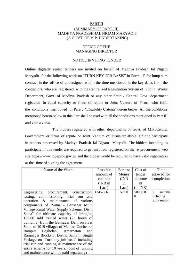
PART II
(SUMMARY OF PART III)
MADHYA PRADESH JAL NIGAM MARYADIT
(A GOVT. OF M.P. UNDERTAKING)
OFFICE OF THE
MANAGING DIRECTOR
NOTICE INVITING TENDER
Online digitally sealed tenders are invited on behalf of Madhya Pradesh Jal Nigam
Maryadit for the following work on "TURN KEY JOB BASIS” in Form - F for lump sum
contract in the office of undersigned within the time mentioned in the key dates from the
contractors, who are registered with the Centralized Registration System of Public Works
Department, Govt. of Madhya Pradesh or any other State / Central Govt. department
registered in equal capacity or firms of repute or Joint Venture of Firms, who fulfil
the conditions mentioned in Para 3 ‘Eligibility Criteria’ herein below. All the conditions
mentioned herein below in this Part shall be read with all the conditions mentioned in Part III
and vice a versa.
The bidders registered with other departments of Govt. of M.P./Central
Government or firms of repute or Joint Venture of Firms are also eligible to participate
in tenders processed by Madhya Pradesh Jal Nigam Maryadit. The bidders intending to
participate in this tender are required to get enrolled/ registered on the e procurement web
site https://www.mpeproc.gov.in and the bidder would be required to have valid registration
at the time of signing the agreement.
Name of the Work Probable
amount of
contract
(INR in
Lacs)
Earnest
Money
(INR
in
Lacs)
Cost of
tender
docume
nt
(in INR)
Time
allowed for
completion
Engineering, procurement, construction, testing, commissioning, trial run and operation & maintenance of various components of "Satna - Bansagar Multi Village Rural Water Supply Scheme, Distt. Satna" for ultimate capacity of bringing 166.00 mld treated water (23 hours of pumping) from the Bansagar Dam on river Sone to 1019 villages of Maihar, Unchehra, Rampur Baghelan, Amarpatan and Ramnagar Blocks of Distric Satna in Single Package on ‘Turn-key job basis’ including trial run and running & maintenance of the entire scheme for 10 years. (cost of running and maintenance will be paid separately)
124527.6 50.00 50000.0
0
30 months
including
rainy season
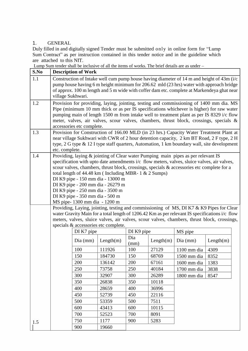
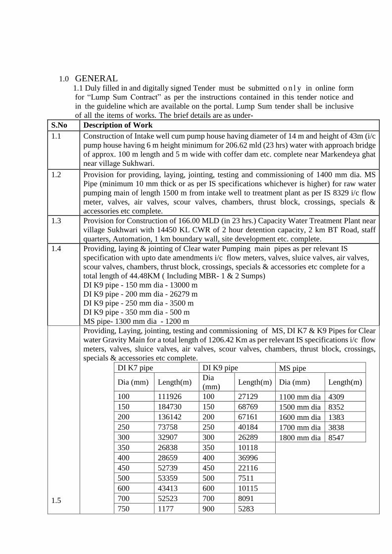
1. GENERAL
Duly filled in and digitally signed Tender must be submitted only in online form for “Lump
Sum Contract” as per instruction contained in this tender notice and in the guideline which
are attached to this NIT. Lump Sum tender shall be inclusive of all the items of works. The brief details are as under –
S.No Description of Work
1.1 Construction of Intake well cum pump house having diameter of 14 m and height of 43m (i/c
pump house having 6 m height minimum for 206.62 mld (23 hrs) water with approach bridge
of approx. 100 m length and 5 m wide with coffer dam etc. complete at Markendeya ghat near
village Sukhwari.
1.2 Provision for providing, laying, jointing, testing and commissioning of 1400 mm dia. MS
Pipe (minimum 10 mm thick or as per IS specifications whichever is higher) for raw water
pumping main of length 1500 m from intake well to treatment plant as per IS 8329 i/c flow
meter, valves, air valves, scour valves, chambers, thrust block, crossings, specials &
accessories etc complete.
1.3 Provision for Construction of 166.00 MLD (in 23 hrs.) Capacity Water Treatment Plant at
near village Sukhwari with CWR of 2 hour detention capacity, 2 km BT Road, 2 F type, 2 H
type, 2 G type & 12 I type staff quarters, Automation, 1 km boundary wall, site development
etc. complete.
1.4 Providing, laying & jointing of Clear water Pumping main pipes as per relevant IS
specification with upto date amendments i/c flow meters, valves, sluice valves, air valves,
scour valves, chambers, thrust block, crossings, specials & accessories etc complete for a
total length of 44.48 km ( Including MBR- 1 & 2 Sumps)
DI K9 pipe - 150 mm dia - 13000 m
DI K9 pipe - 200 mm dia - 26279 m
DI K9 pipe - 250 mm dia - 3500 m
DI K9 pipe - 350 mm dia - 500 m
MS pipe- 1300 mm dia - 1200 m
1.5
Providing, Laying, jointing, testing and commissioning of MS, DI K7 & K9 Pipes for Clear
water Gravity Main for a total length of 1206.42 Km as per relevant IS specifications i/c flow
meters, valves, sluice valves, air valves, scour valves, chambers, thrust block, crossings,
specials & accessories etc complete.
DI K7 pipe DI K9 pipe MS pipe
Dia (mm) Length(m) Dia
(mm) Length(m) Dia (mm) Length(m)
100 111926 100 27129 1100 mm dia 4309
150 184730 150 68769 1500 mm dia 8352
200 136142 200 67161 1600 mm dia 1383
250 73758 250 40184 1700 mm dia 3838
300 32907 300 26289 1800 mm dia 8547
350 26838 350 10118 400 28659 400 36996 450 52739 450 22116 500 53359 500 7511 600 43413 600 10115 700 52523 700 8091 750 1177 900 5283 900 19660
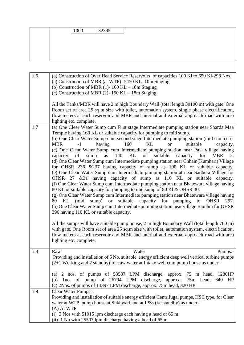
1000 32395
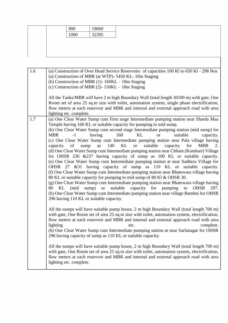
1.6 (a) Construction of Over Head Service Reservoirs of capacities 100 Kl to 650 Kl-298 Nos
(a) Construction of MBR (at WTP)- 5450 KL- 10m Staging
(b) Construction of MBR (1)- 160 KL – 18m Staging
(c) Construction of MBR (2)- 150 KL – 18m Staging
All the Tanks/MBR will have 2 m high Boundary Wall (total length 30100 m) with gate, One
Room set of area 25 sq.m size with toilet, automation system, single phase electrification,
flow meters at each reservoir and MBR and internal and external approach road with area
lighting etc. complete.
1.7 (a) One Clear Water Sump cum First stage Intermediate pumping station near Sharda Maa
Temple having 160 KL or suitable capacity for pumping to mid sump.
(b) One Clear Water Sump cum second stage Intermediate pumping station (mid sump) for
MBR -1 having 160 KL or suitable capacity.
(c) One Clear Water Sump cum Intermediate pumping station near Pala village having
capacity of sump as 140 KL or suitable capacity for MBR 2.
(d) One Clear Water Sump cum Intermediate pumping station near Chhain(Kumhari) Village
for OHSR 236 &237 having capacity of sump as 100 KL or suitable capacity.
(e) One Clear Water Sump cum Intermediate pumping station at near Sadhera Village for
OHSR 27 &31 having capacity of sump as 110 KL or suitable capacity.
(f) One Clear Water Sump cum Intermediate pumping station near Bhatewara village having
80 KL or suitable capacity for pumping to mid sump of 80 Kl & OHSR 30.
(g) One Clear Water Sump cum Intermediate pumping station near Bhatewara village having
80 KL (mid sump) or suitable capacity for pumping to OHSR 297.
(h) One Clear Water Sump cum Intermediate pumping station near village Bamhni for OHSR
296 having 110 KL or suitable capacity.
All the sumps will have suitable pump house, 2 m high Boundary Wall (total length 700 m)
with gate, One Room set of area 25 sq.m size with toilet, automation system, electrification,
flow meters at each reservoir and MBR and internal and external approach road with area
lighting etc. complete.
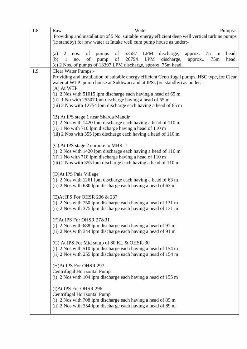
1.8 Raw Water Pumps:-
Providing and installation of 5 No. suitable energy efficient deep well vertical turbine pumps
(2+1 Working and 2 standby) for raw water at Intake well cum pump house as under:-
(a) 2 nos. of pumps of 53587 LPM discharge, approx. 75 m head, 1280HP
(b) 1no. of pump of 26794 LPM discharge, approx.. 75m head, 640 HP
(c) 2Nos. of pumps of 13397 LPM discharge, approx. 75m head, 320 HP
1.9 Clear Water Pumps:-
Providing and installation of suitable energy efficient Centrifugal pumps, HSC type, for Clear
water at WTP pump house at Sukhwari and at IPSs (i/c standby) as under:-
(A) At WTP
(i) 2 Nos with 51015 lpm discharge each having a head of 65 m
(ii) 1 No with 25507 lpm discharge having a head of 65 m
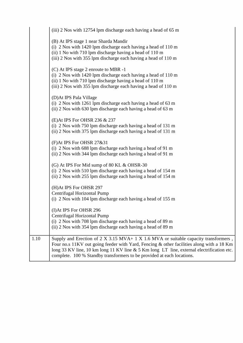
(iii) 2 Nos with 12754 lpm discharge each having a head of 65 m
(B) At IPS stage 1 near Sharda Mandir
(i) 2 Nos with 1420 lpm discharge each having a head of 110 m
(ii) 1 No with 710 lpm discharge having a head of 110 m
(iii) 2 Nos with 355 lpm discharge each having a head of 110 m
(C) At IPS stage 2 enroute to MBR -1
(i) 2 Nos with 1420 lpm discharge each having a head of 110 m
(ii) 1 No with 710 lpm discharge having a head of 110 m
(iii) 2 Nos with 355 lpm discharge each having a head of 110 m
(D)At IPS Pala Village
(i) 2 Nos with 1261 lpm discharge each having a head of 63 m
(ii) 2 Nos with 630 lpm discharge each having a head of 63 m
(E)At IPS For OHSR 236 & 237
(i) 2 Nos with 750 lpm discharge each having a head of 131 m
(ii) 2 Nos with 375 lpm discharge each having a head of 131 m
(F)At IPS For OHSR 27&31
(i) 2 Nos with 688 lpm discharge each having a head of 91 m
(ii) 2 Nos with 344 lpm discharge each having a head of 91 m
(G) At IPS For Mid sump of 80 KL & OHSR-30
(i) 2 Nos with 510 lpm discharge each having a head of 154 m
(ii) 2 Nos with 255 lpm discharge each having a head of 154 m
(H)At IPS For OHSR 297
Centrifugal Horizontal Pump
(i) 2 Nos with 104 lpm discharge each having a head of 155 m
(I)At IPS For OHSR 296
Centrifugal Horizontal Pump
(i) 2 Nos with 708 lpm discharge each having a head of 89 m
(ii) 2 Nos with 354 lpm discharge each having a head of 89 m
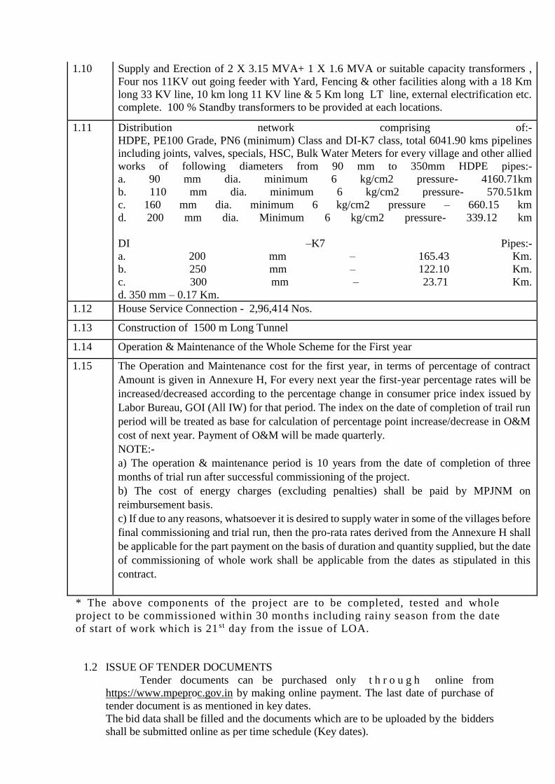
1.10 Supply and Erection of 2 X 3.15 MVA+ 1 X 1.6 MVA or suitable capacity transformers ,
Four no.s 11KV out going feeder with Yard, Fencing & other facilities along with a 18 Km
long 33 KV line, 10 km long 11 KV line & 5 Km long LT line, external electrification etc.
complete. 100 % Standby transformers to be provided at each locations.
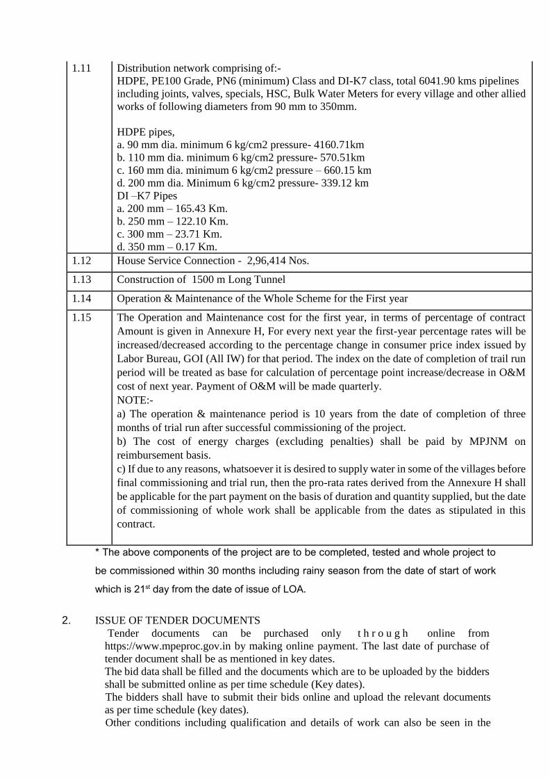
1.11 Distribution network comprising of:-
HDPE, PE100 Grade, PN6 (minimum) Class and DI-K7 class, total 6041.90 kms pipelines
including joints, valves, specials, HSC, Bulk Water Meters for every village and other allied
works of following diameters from 90 mm to 350mm.
HDPE pipes,
a. 90 mm dia. minimum 6 kg/cm2 pressure- 4160.71km
b. 110 mm dia. minimum 6 kg/cm2 pressure- 570.51km
c. 160 mm dia. minimum 6 kg/cm2 pressure – 660.15 km
d. 200 mm dia. Minimum 6 kg/cm2 pressure- 339.12 km
DI –K7 Pipes
a. 200 mm – 165.43 Km.
b. 250 mm – 122.10 Km.
c. 300 mm – 23.71 Km.
d. 350 mm – 0.17 Km.
1.12 House Service Connection - 2,96,414 Nos.
1.13 Construction of 1500 m Long Tunnel
1.14 Operation & Maintenance of the Whole Scheme for the First year
1.15 The Operation and Maintenance cost for the first year, in terms of percentage of contract
Amount is given in Annexure H, For every next year the first-year percentage rates will be
increased/decreased according to the percentage change in consumer price index issued by
Labor Bureau, GOI (All IW) for that period. The index on the date of completion of trail run
period will be treated as base for calculation of percentage point increase/decrease in O&M
cost of next year. Payment of O&M will be made quarterly.
NOTE:-
a) The operation & maintenance period is 10 years from the date of completion of three
months of trial run after successful commissioning of the project.
b) The cost of energy charges (excluding penalties) shall be paid by MPJNM on
reimbursement basis.
c) If due to any reasons, whatsoever it is desired to supply water in some of the villages before
final commissioning and trial run, then the pro-rata rates derived from the Annexure H shall
be applicable for the part payment on the basis of duration and quantity supplied, but the date
of commissioning of whole work shall be applicable from the dates as stipulated in this
contract.
* The above components of the project are to be completed, tested and whole project to
be commissioned within 30 months including rainy season from the date of start of work
which is 21st day from the date of issue of LOA.
2. ISSUE OF TENDER DOCUMENTS
Tender documents can be purchased only t h r o u g h online from
https://www.mpeproc.gov.in by making online payment. The last date of purchase of
tender document shall be as mentioned in key dates.
The bid data shall be filled and the documents which are to be uploaded by the bidders
shall be submitted online as per time schedule (Key dates).
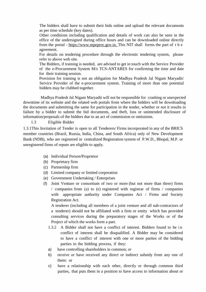
The bidders shall have to submit their bids online and upload the relevant documents
as per time schedule (key dates).
Other conditions including qualification and details of work can also be seen in the
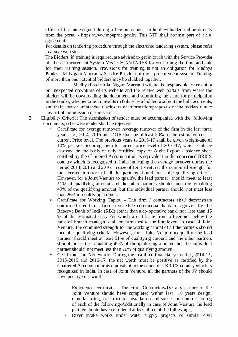
office of the undersigned during office hours and can be downloaded online directly
from the portal - https://www.mpeproc.gov.in. This NIT shall f o r m s part of t h e
agreement.
For details on tendering procedure through the electronic tendering system, please refer
to above web site.
The Bidders, if training is required, are advised to get in touch with the Service Provider
of the e-Procurement System M/s TCS-ANTARES for confirming the time and date
for their training session. Provisions for training is not an obligation for Madhya
Pradesh Jal Nigam Maryadit/ Service Provider of the e-procurement system. Training
of more than one potential bidders may be clubbed together.
Madhya Pradesh Jal Nigam Maryadit will not be responsible for crashing
or unexpected downtime of its website and the related web portals from where the
bidders will be downloading the documents and submitting the same for participation
in the tender, whether or not it results in failure by a bidder to submit the bid documents,
and theft, loss or unintended disclosure of information/proposals of the bidders due to
any act of commission or omission.
3. Eligibility Criteria: The submission of tender must be accompanied with the following
documents; otherwise tender shall be rejected-
• Certificate for average turnover: Average turnover of the firm in the last three
years, i.e., 2014, 2015 and 2016 shall be at-least 50% of the estimated cost at current Price level. The previous years to 2016-17 shall be given weight-age of
10% per year to bring them to current price level of 2016-17, which shall be assessed on the basis of duly certified copy of Audit Report / balance sheet
certified by the Chartered Accountant or its equivalent in the concerned BRICS country which is recognized in India indicating the average turnover during the
period 2014, 2015 and 2016. In case of Joint Venture, the combined strength for the average turnover of all the partners should meet the qualifying criteria.
However, for a Joint Venture to qualify, the lead partner should meet at least
51% of qualifying amount and the other partners should meet the remaining 49% of the qualifying amount, but the individual partner should not meet less
than 26% of qualifying amount.
• Certificate for Working Capital - The firm / contractors shall demonstrate
confirmed credit line from a schedule commercial bank recognized by the Reserve Bank of India (RBI) (other than a co-operative bank) not less than 15
% of the estimated cost. For which a certificate from officer not below the rank of branch manager shall be furnished to the Employer. In case of Joint
Venture, the combined strength for the working capital of all the partners should meet the qualifying criteria. However, for a Joint Venture to qualify, the lead
partner should meet at least 51% of qualifying amount and the other partners should meet the remaining 49% of the qualifying amount, but the individual
partner should not meet less than 26% of qualifying amount.
• Certificate for Net worth: During the last three financial years, i.e., 2014-15, 2015-2016 and 2016-17, the net worth must be positive as certified by the
Chartered Accountant or its equivalent in the concerned BRICS country which is recognized in India. In case of Joint Venture, all the partners of the JV should
have positive net-worth.
Experience certificate - The Firms/Contractors/JV/ any partner of the
Joint Venture should have completed within last 10 years design,
manufacturing, construction, installation and successful commissioning
of each of the following-Additionally in case of Joint Venture the lead
partner should have completed at least three of the following _-
• River intake works under water supply projects or similar civil

engineering infrastructure projects of at least 33% of the desired capacity
in a single contract.
• Providing/laying water supply pipelines of diameter 80mm or above of
any material for minimum 33% of the total length given in this contract.
• Water treatment plant of at least 33% of the desired capacity in a single
contract.
• Clear water reservoir (any drinking water storage RCC structure) of at
least 50% of the desired maximum capacity in a single contract.
• Pump – motor works of at least 33% of the pumping capacity for the largest
pumping unit in the desired project including all civil, mechanical and electrical works in a single contract.
➢ Firms / Contractors / JV / any partner of the Joint Venture, who are executing the works of similar nature and of capacity at par
or above of this minimum requirement and have completed more
than 75 % of job can also be considered, provided they produce certificates from the officer not below the rank of Executive
Engineer or its equivalent in the concerned BRICS country. Such certificate must describe that the work was/is being executed for
the extended period without penalty.
➢ Experience of works with reputed private firm shall also be
considered.
➢ Experience of similar nature of works may also be considered,
which includes works with its similarity in quantitative infrastructural works, its functional fulfillment, methodology and
complexity such as construction of bridge pier with well sinking type
foundation will be considered for intake well experience.
4. Income tax clearance certificate from the competent authority or PAN Card and a copy
each of Income Tax Return filed, for the financial years 2014-15, 2015-16 and 2016-17.
5. Valid registration certificate in case of registered contractors and previous year’s (2016-17)
balance sheet in case of firm of repute/ all partners of Joint Venture.
6. Firms incorporated in any of the BRICS member countries (Brazil, Russia, India, China,
and South Africa) of New Development Bank (NDB) are only eligible to apply.
7. The applicants shall get the above documents verified from the originals, at least a day
before Financial bid (Envelope-C) Opening Date; else their tender will not be entertained.
This tender notice can also be seen on the Madhya Pradesh Jal Nigam’s web site
www.mpjalnigam.co.in.
Managing Director
Madhya Pradesh Jal Nigam Maryadit
Vindhyachal Bhawan, Bhopal

PART III
(Detailed Notice Inviting Tender)
MADHYA PRADESH JAL NIGAM MARYADIT
(A GOVT. OF M.P. UNDERTAKING)
OFFICE OF THE MANAGING DIRECTOR
M.P. JAL NIGAM MARYADIT, BHOPAL
DETAILED NOTICE INVITING TENDER
Online digitally sealed tenders are invited on behalf of Madhya Pradesh Jal Nigam
Maryadit for the following work on "TURN KEY JOB BASIS” in Form – F for lump sum
contract in the office of undersigned within the time mentioned in the key dates from the
contractors, who are registered with the Centralized Registration System of Public Works
Department, Govt. of Madhya Pradesh or any other State / Central Govt. department
registered in equal capacity or firms of repute or Joint Venture of Firms, who fulfil
the conditions mentioned in Para 3 ‘Eligibility Criteria' herein below. All the conditions
mentioned in this Part shall be read with all the conditions mentioned in Part II and vice a
versa.
The bidders registered with other departments of Govt. of M.P./Central Government or
firms of repute or Joint Venture of Firms are also eligible to participate in tenders
processed by Madhya Pradesh Jal Nigam Maryadit. The bidders intending to participate in
this tender are required to get enrolled/ registered on the e procurement web site
https://www.mpeproc.gov.in, the bidder would be required to have valid registration at the
time of signing the agreement.
Name of the Work
Probable
amount
of
contract
(INR in
Lacs)
Earnest
Money
(INR in
Lacs)
Cost of
tender
documen
t
(in INR)
Time
allowed
for
completi
on
Engineering, procurement, construction, testing,
commissioning, trial run and operation & maintenance
of various components of "Satna - Bansagar Multi
Village Rural Water Supply Scheme, Distt. Satna" for
ultimate capacity of bringing 166.00 mld treated water
(23 hours of pumping) from the Bansagar Dam on
river Sone to 1019 villages of Maihar, Unchehra,
Rampur Baghelan, Amarpatan and Ramnagar Blocks
of Distric Satna in Single Package on ‘Turn-key job
basis’ including trial run and running & maintenance
of the entire scheme for 10 years. (cost of running and
maintenance will be paid separately)
124527.6 50.00 50000.00 30 months
including
rainy
season
1.0 GENERAL 1.1 Duly filled in and digitally signed Tender must be submitted o n l y in online form
for “Lump Sum Contract” as per the instructions contained in this tender notice and
in the guideline which are available on the portal. Lump Sum tender shall be inclusive
of all the items of works. The brief details are as under-
S.No Description of Work
1.1 Construction of Intake well cum pump house having diameter of 14 m and height of 43m (i/c
pump house having 6 m height minimum for 206.62 mld (23 hrs) water with approach bridge
of approx. 100 m length and 5 m wide with coffer dam etc. complete near Markendeya ghat
near village Sukhwari.
1.2 Provision for providing, laying, jointing, testing and commissioning of 1400 mm dia. MS
Pipe (minimum 10 mm thick or as per IS specifications whichever is higher) for raw water
pumping main of length 1500 m from intake well to treatment plant as per IS 8329 i/c flow
meter, valves, air valves, scour valves, chambers, thrust block, crossings, specials &
accessories etc complete.
1.3 Provision for Construction of 166.00 MLD (in 23 hrs.) Capacity Water Treatment Plant near
village Sukhwari with 14450 KL CWR of 2 hour detention capacity, 2 km BT Road, staff
quarters, Automation, 1 km boundary wall, site development etc. complete.
1.4 Providing, laying & jointing of Clear water Pumping main pipes as per relevant IS
specification with upto date amendments i/c flow meters, valves, sluice valves, air valves,
scour valves, chambers, thrust block, crossings, specials & accessories etc complete for a
total length of 44.48KM ( Including MBR- 1 & 2 Sumps)
DI K9 pipe - 150 mm dia - 13000 m
DI K9 pipe - 200 mm dia - 26279 m
DI K9 pipe - 250 mm dia - 3500 m
DI K9 pipe - 350 mm dia - 500 m
MS pipe- 1300 mm dia - 1200 m
1.5
Providing, Laying, jointing, testing and commissioning of MS, DI K7 & K9 Pipes for Clear
water Gravity Main for a total length of 1206.42 Km as per relevant IS specifications i/c flow
meters, valves, sluice valves, air valves, scour valves, chambers, thrust block, crossings,
specials & accessories etc complete.
DI K7 pipe DI K9 pipe MS pipe
Dia (mm) Length(m) Dia
(mm) Length(m) Dia (mm) Length(m)
100 111926 100 27129 1100 mm dia 4309
150 184730 150 68769 1500 mm dia 8352
200 136142 200 67161 1600 mm dia 1383
250 73758 250 40184 1700 mm dia 3838
300 32907 300 26289 1800 mm dia 8547
350 26838 350 10118 400 28659 400 36996 450 52739 450 22116 500 53359 500 7511 600 43413 600 10115 700 52523 700 8091 750 1177 900 5283
900 19660 1000 32395
1.6 (a) Construction of Over Head Service Reservoirs of capacities 100 Kl to 650 Kl - 298 Nos
(a) Construction of MBR (at WTP)- 5450 KL- 10m Staging
(b) Construction of MBR (1)- 160KL – 18m Staging
(c) Construction of MBR (2)- 150KL – 18m Staging
All the Tanks/MBR will have 2 m high Boundary Wall (total length 30100 m) with gate, One
Room set of area 25 sq.m size with toilet, automation system, single phase electrification,
flow meters at each reservoir and MBR and internal and external approach road with area
lighting etc. complete.
1.7 (a) One Clear Water Sump cum First stage Intermediate pumping station near Sharda Maa
Temple having 160 KL or suitable capacity for pumping to mid sump.
(b) One Clear Water Sump cum second stage Intermediate pumping station (mid sump) for
MBR -1 having 160 KL or suitable capacity.
(c) One Clear Water Sump cum Intermediate pumping station near Pala village having
capacity of sump as 140 KL or suitable capacity for MBR 2.
(d) One Clear Water Sump cum Intermediate pumping station near Chhain (Kumhari) Village
for OHSR 236 &237 having capacity of sump as 100 KL or suitable capacity.
(e) One Clear Water Sump cum Intermediate pumping station at near Sadhera Village for
OHSR 27 &31 having capacity of sump as 110 KL or suitable capacity.
(f) One Clear Water Sump cum Intermediate pumping station near Bhatewara village having
80 KL or suitable capacity for pumping to mid sump of 80 Kl & OHSR 30.
(g) One Clear Water Sump cum Intermediate pumping station near Bhatewara village having
80 KL (mid sump) or suitable capacity for pumping to OHSR 297.
(h) One Clear Water Sump cum Intermediate pumping station near village Bamhni for OHSR
296 having 110 KL or suitable capacity.
All the sumps will have suitable pump house, 2 m high Boundary Wall (total length 700 m)
with gate, One Room set of area 25 sq.m size with toilet, automation system, electrification,
flow meters at each reservoir and MBR and internal and external approach road with area
lighting etc. complete.
(h) One Clear Water Sump cum Intermediate pumping station at near Sarlanagar for OHSR
296 having capacity of sump as 110 KL or suitable capacity.
All the sumps will have suitable pump house, 2 m high Boundary Wall (total length 700 m)
with gate, One Room set of area 25 sq.m size with toilet, automation system, electrification,
flow meters at each reservoir and MBR and internal and external approach road with area
lighting etc. complete.
1.8 Raw Water Pumps:-
Providing and installation of 5 No. suitable energy efficient deep well vertical turbine pumps
(ic standby) for raw water at Intake well cum pump house as under:-
(a) 2 nos. of pumps of 53587 LPM discharge, approx. 75 m head,
(b) 1 no. of pump of 26794 LPM discharge, approx.. 75m head,
(c) 2 Nos. of pumps of 13397 LPM discharge, approx. 75m head,
1.9 Clear Water Pumps:-
Providing and installation of suitable energy efficient Centrifugal pumps, HSC type, for Clear
water at WTP pump house at Sukhwari and at IPSs (i/c standby) as under:-
(A) At WTP
(i) 2 Nos with 51015 lpm discharge each having a head of 65 m
(ii) 1 No with 25507 lpm discharge having a head of 65 m
(iii) 2 Nos with 12754 lpm discharge each having a head of 65 m
(B) At IPS stage 1 near Sharda Mandir
(i) 2 Nos with 1420 lpm discharge each having a head of 110 m
(ii) 1 No with 710 lpm discharge having a head of 110 m
(iii) 2 Nos with 355 lpm discharge each having a head of 110 m
(C) At IPS stage 2 enroute to MBR -1
(i) 2 Nos with 1420 lpm discharge each having a head of 110 m
(ii) 1 No with 710 lpm discharge having a head of 110 m
(iii) 2 Nos with 355 lpm discharge each having a head of 110 m
(D)At IPS Pala Village
(i) 2 Nos with 1261 lpm discharge each having a head of 63 m
(ii) 2 Nos with 630 lpm discharge each having a head of 63 m
(E)At IPS For OHSR 236 & 237
(i) 2 Nos with 750 lpm discharge each having a head of 131 m
(ii) 2 Nos with 375 lpm discharge each having a head of 131 m
(F)At IPS For OHSR 27&31
(i) 2 Nos with 688 lpm discharge each having a head of 91 m
(ii) 2 Nos with 344 lpm discharge each having a head of 91 m
(G) At IPS For Mid sump of 80 KL & OHSR-30
(i) 2 Nos with 510 lpm discharge each having a head of 154 m
(ii) 2 Nos with 255 lpm discharge each having a head of 154 m
(H)At IPS For OHSR 297
Centrifugal Horizontal Pump
(i) 2 Nos with 104 lpm discharge each having a head of 155 m
(I)At IPS For OHSR 296
Centrifugal Horizontal Pump
(i) 2 Nos with 708 lpm discharge each having a head of 89 m
(ii) 2 Nos with 354 lpm discharge each having a head of 89 m
1.10 Supply and Erection of 2 X 3.15 MVA+ 1 X 1.6 MVA or suitable capacity transformers ,
Four nos 11KV out going feeder with Yard, Fencing & other facilities along with a 18 Km
long 33 KV line, 10 km long 11 KV line & 5 Km long LT line, external electrification etc.
complete. 100 % Standby transformers to be provided at each locations.
1.11 Distribution network comprising of:-
HDPE, PE100 Grade, PN6 (minimum) Class and DI-K7 class, total 6041.90 kms pipelines
including joints, valves, specials, HSC, Bulk Water Meters for every village and other allied
works of following diameters from 90 mm to 350mm HDPE pipes:-
a. 90 mm dia. minimum 6 kg/cm2 pressure- 4160.71km
b. 110 mm dia. minimum 6 kg/cm2 pressure- 570.51km
c. 160 mm dia. minimum 6 kg/cm2 pressure – 660.15 km
d. 200 mm dia. Minimum 6 kg/cm2 pressure- 339.12 km
DI –K7 Pipes:-
a. 200 mm – 165.43 Km.
b. 250 mm – 122.10 Km.
c. 300 mm – 23.71 Km.
d. 350 mm – 0.17 Km.
1.12 House Service Connection - 2,96,414 Nos.
1.13 Construction of 1500 m Long Tunnel
1.14 Operation & Maintenance of the Whole Scheme for the First year
1.15 The Operation and Maintenance cost for the first year, in terms of percentage of contract
Amount is given in Annexure H, For every next year the first-year percentage rates will be
increased/decreased according to the percentage change in consumer price index issued by
Labor Bureau, GOI (All IW) for that period. The index on the date of completion of trail run
period will be treated as base for calculation of percentage point increase/decrease in O&M
cost of next year. Payment of O&M will be made quarterly.
NOTE:-
a) The operation & maintenance period is 10 years from the date of completion of three
months of trial run after successful commissioning of the project.
b) The cost of energy charges (excluding penalties) shall be paid by MPJNM on
reimbursement basis.
c) If due to any reasons, whatsoever it is desired to supply water in some of the villages before
final commissioning and trial run, then the pro-rata rates derived from the Annexure H shall
be applicable for the part payment on the basis of duration and quantity supplied, but the date
of commissioning of whole work shall be applicable from the dates as stipulated in this
contract.
* The above components of the project are to be completed, tested and whole
project to be commissioned within 30 months including rainy season from the date
of start of work which is 21 st day from the issue of LOA.
1.2 ISSUE OF TENDER DOCUMENTS
Tender documents can be purchased only t h r o u g h online from
https://www.mpeproc.gov.in by making online payment. The last date of purchase of
tender document is as mentioned in key dates.
The bid data shall be filled and the documents which are to be uploaded by the bidders
shall be submitted online as per time schedule (Key dates).
The bidders shall have to submit their bids online and upload the relevant documents
as per time schedule (key dates).
Other conditions including qualification and details of work can also be seen in the
office of the undersigned during office hours and can be downloaded online directly
from the portal - https://www.mpeproc.gov.in. This NIT shall forms the part of t h e
agreement.
For details on tendering procedure through the electronic tendering system, please
refer to above web site.
The Bidders, if training is needed, are advised to get in touch with the Service Provider
of the e-Procurement System M/s TCS-ANTARES for confirming the time and date
for their training session.
Provision for training is not an obligation for Madhya Pradesh Jal Nigam Maryadit/
Service Provider of the e-procurement system. Training of more than one potential
bidders may be clubbed together.
Madhya Pradesh Jal Nigam Maryadit will not be responsible for crashing or unexpected
downtime of its website and the related web portals from where the bidders will be downloading
the documents and submitting the same for participation in the tender, whether or not it results in
failure by a bidder to submit the bid documents, and theft, loss or unintended disclosure of
information/proposals of the bidders due to an act of commission or omissions.
1.3 Eligible Bidder
1.3.1This Invitation of Tender is open to all Tenderers/ Firms incorporated in any of the BRICS
member countries (Brazil, Russia, India, China, and South Africa) only of New Development
Bank (NDB), who are registered in centralized Registration system of P.W.D., Bhopal, M.P. or
unregistered firms of repute are eligible to apply.
(a) Individual Person/Proprietor
(b) Proprietary firm
(c) Partnership firm
(d) Limited company or limited corporation
(e) Government Undertaking / Enterprises
(f) Joint Venture or consortium of two or more (but not more than three) firms
/ companies from (a) to (e) registered with registrar of firms / companies
with appropriate authority under Companies Act / Firms and Society
Registration Act.
A tenderer (including all members of a joint venture and all sub-contractors of
a tenderer) should not be affiliated with a firm or entity which has provided
consulting services during the preparatory stages of the Works or of the
Project of which the works form a part.
1.3.2 A Bidder shall not have a conflict of interest. Bidders found to be i n
conflict of interest shall be disqualified. A Bidder may be considered
to have a conflict of interest with one or more parties of the bidding
parties in the bidding process, if they:
a) have controlling shareholders in common; or
b) receive or have received any direct or indirect subsidy from any one of
them: or
c) have a relationship with each other, directly or through common third
parties, that puts them in a position to have access to information about or
influence on the Bid of another Bidder that influence the decisions of the
MP Jal Nigam regarding the bidding process.
1.3.3 Government-owned / undertaking enterprises in India shall be eligible if
they are legally and financially autonomous and operate in accordance with
law.
Bidders shall provide such evidence of their continued eligibility up to the
satisfaction of the MPJNM.
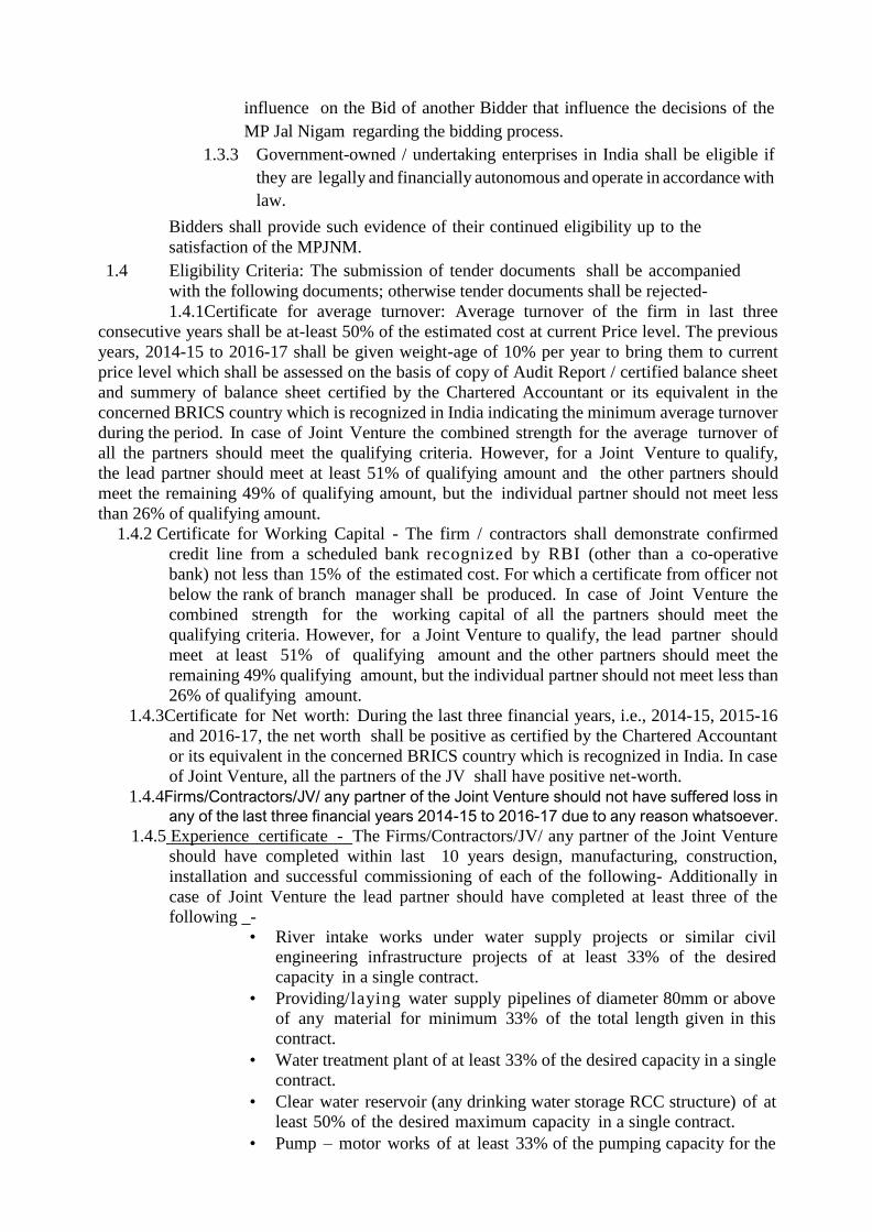
1.4 Eligibility Criteria: The submission of tender documents shall be accompanied
with the following documents; otherwise tender documents shall be rejected-
1.4.1Certificate for average turnover: Average turnover of the firm in last three
consecutive years shall be at-least 50% of the estimated cost at current Price level. The previous
years, 2014-15 to 2016-17 shall be given weight-age of 10% per year to bring them to current
price level which shall be assessed on the basis of copy of Audit Report / certified balance sheet
and summery of balance sheet certified by the Chartered Accountant or its equivalent in the
concerned BRICS country which is recognized in India indicating the minimum average turnover
during the period. In case of Joint Venture the combined strength for the average turnover of
all the partners should meet the qualifying criteria. However, for a Joint Venture to qualify,
the lead partner should meet at least 51% of qualifying amount and the other partners should
meet the remaining 49% of qualifying amount, but the individual partner should not meet less
than 26% of qualifying amount.
1.4.2 Certificate for Working Capital - The firm / contractors shall demonstrate confirmed
credit line from a scheduled bank recognized by RBI (other than a co-operative
bank) not less than 15% of the estimated cost. For which a certificate from officer not
below the rank of branch manager shall be produced. In case of Joint Venture the
combined strength for the working capital of all the partners should meet the
qualifying criteria. However, for a Joint Venture to qualify, the lead partner should
meet at least 51% of qualifying amount and the other partners should meet the
remaining 49% qualifying amount, but the individual partner should not meet less than
26% of qualifying amount.
1.4.3Certificate for Net worth: During the last three financial years, i.e., 2014-15, 2015-16
and 2016-17, the net worth shall be positive as certified by the Chartered Accountant
or its equivalent in the concerned BRICS country which is recognized in India. In case
of Joint Venture, all the partners of the JV shall have positive net-worth.
1.4.4Firms/Contractors/JV/ any partner of the Joint Venture should not have suffered loss in
any of the last three financial years 2014-15 to 2016-17 due to any reason whatsoever.
1.4.5 Experience certificate - The Firms/Contractors/JV/ any partner of the Joint Venture
should have completed within last 10 years design, manufacturing, construction,
installation and successful commissioning of each of the following- Additionally in
case of Joint Venture the lead partner should have completed at least three of the
following _-
• River intake works under water supply projects or similar civil
engineering infrastructure projects of at least 33% of the desired
capacity in a single contract.
• Providing/laying water supply pipelines of diameter 80mm or above
of any material for minimum 33% of the total length given in this
contract.
• Water treatment plant of at least 33% of the desired capacity in a single
contract.
• Clear water reservoir (any drinking water storage RCC structure) of at
least 50% of the desired maximum capacity in a single contract.
• Pump – motor works of at least 33% of the pumping capacity for the
largest pumping unit in the desired project including all civil,
mechanical and electrical works in a single contract.
➢ Firms / Contractors / JV / any partner of the Joint Venture, who are
executing the works of similar nature and of capacity at par or above
of this minimum requirement and have completed more than 75% of job
can also be considered, provided they produce certificates from the
officer not below the rank of Executive Engineer or equivalent in the
concerned BRICS country. Such certificate should also describe that the
work was/is being executed for the extended period without penalty.
➢ Experience of works with reputed private firms shall also be considered.
➢ Experience of similar nature of works may also be considered, which includes works with its similarity in quantitative infrastructural works,
its functional fulfillment, methodology and complexity such as construction of bridge pier with well sinking type foundation will be
considered for intake well experience.
1.4.6 Income tax clearance certificate from the competent authority and copy of PAN
Card and copy of Income Tax Returns filed, for the financial years 2014-15, 2015-16
and 2016-17
1.4.7 Valid registration certificate in case of registered contractors and previous year’s
(2016-17) balance sheet in case of firm of repute/ all partners of Joint Venture.
1.5 The applicants shall get the above documents verified from the originals, at least a
day before Financial bid (Envelope-C) Open Date; else their tender will not be
entertained.
1.6 Any other information or details in connection with work can be obtained from the
office of the undersigned during office hours on any working day except on the day of
opening of tenders.
1.7 The tender must be in Form 'F' for lump-sum-contract duly filled in as per
instructions contained in detailed notice and said tender forms.
1.8 No two or more concerns/firms etc. in which an individual is interested as a Proprietor
and/or partner shall tender for the execution of the same work, if they do so all such
tenders are liable to be rejected.
1.9 Not more than one tender shall be submitted by a contractor or by a firm of contractors.
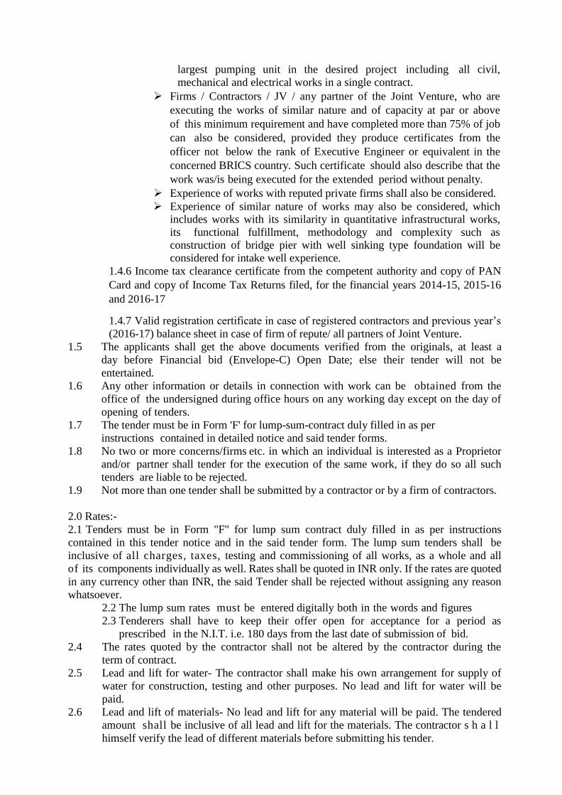
2.0 Rates:-
2.1 Tenders must be in Form "F" for lump sum contract duly filled in as per instructions
contained in this tender notice and in the said tender form. The lump sum tenders shall be
inclusive of all charges, taxes, testing and commissioning of all works, as a whole and all
of its components individually as well. Rates shall be quoted in INR only. If the rates are quoted
in any currency other than INR, the said Tender shall be rejected without assigning any reason
whatsoever.
2.2 The lump sum rates must be entered digitally both in the words and figures
2.3 Tenderers shall have to keep their offer open for acceptance for a period as
prescribed in the N.I.T. i.e. 180 days from the last date of submission of bid.
2.4 The rates quoted by the contractor shall not be altered by the contractor during the
term of contract.
2.5 Lead and lift for water- The contractor shall make his own arrangement for supply of
water for construction, testing and other purposes. No lead and lift for water will be
paid.
2.6 Lead and lift of materials- No lead and lift for any material will be paid. The tendered
amount shall be inclusive of all lead and lift for the materials. The contractor s h a l l
himself verify the lead of different materials before submitting his tender.
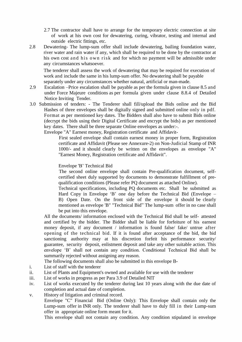
2.7 The contractor shall have to arrange for the temporary electric connection at site
of work at his own cost for dewatering, curing, vibrator, testing and internal and
outside electric fittings, etc.
2.8 Dewatering- The lump-sum offer shall include dewatering, bailing foundation water,
river water and rain water if any, which shall be required to be done by the contractor at
his own cost and h i s own r i sk and for which no payment will be admissible under
any circumstances whatsoever.
The tenderer shall assess the work of dewatering that may be required for execution of
work and include the same in his lump-sum offer. No dewatering shall be payable
separately under any circumstances whether natural, artificial or man-made.
2.9 Escalation –Price escalation shall be payable as per the formula given in clause 8.5 and
under Force Majeure conditions as per formula given under clause 8.8.4 of Detailed
Notice Inviting Tender.
3.0 Submission of tenders: - The Tenderer shall fill/upload the Bids online and the Bid
Hashes of three envelopes shall be digitally signed and submitted online only in pdf.
Format as per mentioned key dates. The Bidders shall also have to submit Bids online
(decrypt the bids using their Digital Certificate and encrypt the bids) as per mentioned
key dates. There shall be three separate Online envelopes as under:-.
Envelope "A" Earnest money, Registration certificate and Affidavit-
First sealed envelope shall contain earnest money in proper form, Registration
certificate and Affidavit (Please see Annexure-2) on Non-Judicial Stamp of INR
1000/- and it should clearly be written on the envelopes as envelope "A"
"Earnest Money, Registration certificate and Affidavit".
Envelope 'B’ Technical Bid
The second online envelope shall contain Pre-qualification document, self-
certified sheet duly supported by documents to demonstrate fulfillment of pre-
qualification conditions (Please refer PQ document as attached Online).
Technical specifications, including PQ documents etc. Shall be submitted as
Hard Copy in Envelope ‘B’ one day before the Technical Bid (Envelope –
B) Open Date. On the front side of the envelope it should be clearly
mentioned as envelope 'B" "Technical Bid” The lump-sum offer in no case shall
be put into this envelope.
All the documents/ information enclosed with the Technical Bid shall be self- attested
and certified by the bidder. The Bidder shall be liable for forfeiture of his earnest
money deposit, if any document / information is found false/ fake/ untrue after
opening of the technical bid. If it is found after acceptance of the bid, the bid
sanctioning authority may at his discretion forfeit his performance security/
guarantee, security deposit, enlistment deposit and take any other suitable action. This
envelope ‘B’ shall not contain any condition. Conditional Technical Bid shall be
summarily rejected without assigning any reason.
The following documents shall also be submitted in this envelope B-
i. List of staff with the tenderer
ii. List of Plants and Equipment's owned and available for use with the tenderer
iii. List of works in progress as per Para 3.9 of Detailed NIT
iv. List of works executed by the tenderer during last 10 years along with the due date of
completion and actual date of completion.
v. History of litigation and criminal record.
Envelope "C" Financial Bid (Online Only): This Envelope shall contain only the
Lump-sum offer in INR only. The tenderer shall have to duly fill i n their Lump-sum
offer in appropriate online form meant for it.
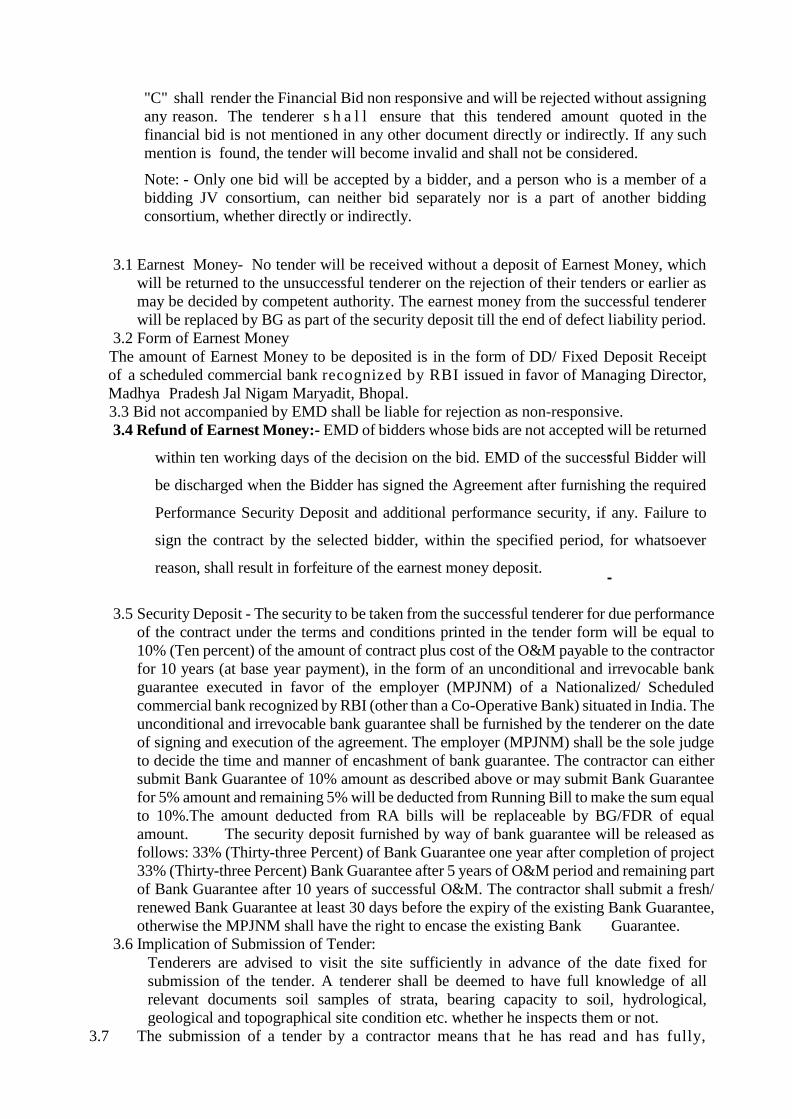
This envelope shall not contain any condition. Any condition stipulated in envelope
"C" shall render the Financial Bid non responsive and will be rejected without assigning
any reason. The tenderer s h a l l ensure that this tendered amount quoted in the
financial bid is not mentioned in any other document directly or indirectly. If any such
mention is found, the tender will become invalid and shall not be considered.
Note: - Only one bid will be accepted by a bidder, and a person who is a member of a
bidding JV consortium, can neither bid separately nor is a part of another bidding
consortium, whether directly or indirectly.
3.1 Earnest Money- No tender will be received without a deposit of Earnest Money, which
will be returned to the unsuccessful tenderer on the rejection of their tenders or earlier as
may be decided by competent authority. The earnest money from the successful tenderer
will be replaced by BG as part of the security deposit till the end of defect liability period.
3.2 Form of Earnest Money
The amount of Earnest Money to be deposited is in the form of DD/ Fixed Deposit Receipt
of a scheduled commercial bank recognized by RBI issued in favor of Managing Director,
Madhya Pradesh Jal Nigam Maryadit, Bhopal.
3.3 Bid not accompanied by EMD shall be liable for rejection as non-responsive.
3.4 Refund of Earnest Money:- EMD of bidders whose bids are not accepted will be returned
within ten working days of the decision on the bid. EMD of the successful Bidder will
be discharged when the Bidder has signed the Agreement after furnishing the required
Performance Security Deposit and additional performance security, if any. Failure to
sign the contract by the selected bidder, within the specified period, for whatsoever
reason, shall result in forfeiture of the earnest money deposit.
3.5 Security Deposit - The security to be taken from the successful tenderer for due performance
of the contract under the terms and conditions printed in the tender form will be equal to
10% (Ten percent) of the amount of contract plus cost of the O&M payable to the contractor
for 10 years (at base year payment), in the form of an unconditional and irrevocable bank
guarantee executed in favor of the employer (MPJNM) of a Nationalized/ Scheduled
commercial bank recognized by RBI (other than a Co-Operative Bank) situated in India. The
unconditional and irrevocable bank guarantee shall be furnished by the tenderer on the date
of signing and execution of the agreement. The employer (MPJNM) shall be the sole judge
to decide the time and manner of encashment of bank guarantee. The contractor can either
submit Bank Guarantee of 10% amount as described above or may submit Bank Guarantee
for 5% amount and remaining 5% will be deducted from Running Bill to make the sum equal
to 10%.The amount deducted from RA bills will be replaceable by BG/FDR of equal
amount. The security deposit furnished by way of bank guarantee will be released as
follows: 33% (Thirty-three Percent) of Bank Guarantee one year after completion of project
33% (Thirty-three Percent) Bank Guarantee after 5 years of O&M period and remaining part
of Bank Guarantee after 10 years of successful O&M. The contractor shall submit a fresh/
renewed Bank Guarantee at least 30 days before the expiry of the existing Bank Guarantee,
otherwise the MPJNM shall have the right to encase the existing Bank Guarantee.
3.6 Implication of Submission of Tender:
Tenderers are advised to visit the site sufficiently in advance of the date fixed for
submission of the tender. A tenderer shall be deemed to have full knowledge of all
relevant documents soil samples of strata, bearing capacity to soil, hydrological,
geological and topographical site condition etc. whether he inspects them or not.
3.7 The submission of a tender by a contractor means that he has read and has fully,
completely and particularly understood the notice inviting tender, conditions of
tender and all the contract documents and has made himself aware of all the standards
and specifications in this respect, laid down in the National Building Code, relevant I.S.
code and IS Specification, IRC specification. CPHEEO Manual on Water Supply and
Treatment, Annexure 'E' giving the scope and specification of the work to be done and
the conditions of contract, the site of work and quarries with their approaches etc. and
h a s satisfied himself regarding the suitability and availability of the materials at
the quarries. The responsibility of opening new quarries and construction and
maintenance of approaches shall lie wholly with the contractor.
3.8 Income Tax Clearance Certificate: -
An income tax clearance certificate in the form printed as Annexure "D" (Appendix
2.10 to PWD Manual Vol. - II Part-I) from the Income Tax Officer concerned or a
certificate from the Income Tax authority that the assessment is under consideration at
the time of submission of tender shall have to be submitted by the contractor/firm
before tender documents can be issued to him. In later case the I.T. Clearance certificate
for previous financial year will have to be submitted. In absence of I.T.C.C. the tenderer
has to submit copies of PAN and Income Tax Return filed, for the financial years 2014-
15, 2015-16, and 2016-17. This condition shall be applicable for each partner, in case the
tenderer is participating as Joint Venture.
3.9 List of works in progress - The tender must be accompanied by a list of a l l t h e
o n g o i n g contracts held by the tenderer at the time of submitting the tender in the
department and elsewhere showing therein.
(i) Amount of each contract (ii) Balance of work remaining to be done.
3.10 Prohibited Relationship: The contractor shall not be permitted to s u b mi t h i s
tender for works in the Project Implementation Unit responsible for forward and
execution of this contract in which his near relatives are posted. He shall intimate names
of his near relatives working in the Government of Madhya Pradesh Mantralaya, PHE
Department and Madhya Pradesh Jal Nigam Maryadit, Bhopal. He shall also intimate
the names of persons working with him in any capacity of subsequently employed by
him and are near relatives of any gazetted officer in the M.P. Government, Mantralaya,
Public Health Engineering Department.
Any breach of this condition by the contractor shall render him liable to be removed
from the approved list of registered contractors.
NOTE: By the terms near relative is meant wife, husband, parents, sons, daughters,
grandsons, grand daughters, brothers and sisters, brothers in law, sisters in law, father in
law and mother in law.
3.11 The lump-sum rate in INR shal l be entered digitally both in words and figures
For any discrepancy in amount mentioned in figures and words, the amount in words
shall be considered.
3.12 The tender must be signed by the owner/partner of the firm or their authorized
signatory. Each tenderer shall mention the full name, residence and place of business of the person signing the tender and this information shall be signed by the tenderer
with his usual signature. Tender by partnership firms shall mention the full names and
address of all partners. An attested copy of the constitution of the firm and the registration number of the firm shall be furnished in such a case. In case of Joint venture the Lead
partner having the authority to sign the Agreement shall place his/her signature. Tender by corporation shall be signed with the legal name of Corporation followed by the full
name and State of incorporation, and signature followed with designation of the President/Secretary or other persons authorized to sign it.
3.13 Deleted.
3.14 The layout plan and designs will be subjected to the approval of the department
and can be altered to suit the specific departmental requirement and the contractor shall
have no extra claim on that account. The responsibility for the Planning, design,
construction, erection, commissioning and testing will however rest solely with the
contractor. He will have to rectify the defect immediately within a fortnight and when
noticed either during construction period or after
3.15 The tender of one contractor for works shall not be seen, witnessed, or examined
by other contractor or contractors who himself/themselves has/have submitted the
tender for the same work. Failure to observe this condition shall render the tender of the
contractor tendering as well as of those seeing, witnessing, or examining the tender liable
for rejection.
3.16 Detailed specification and leaflets giving make etc. for all the components shall
be submitted with the tender.
3.17 Tender of any contractor who proposes any additions, deletion, alternations,
variation, or modification to any of the conditions laid down in any of the documents
prescribed by MPJNM in this regard is liable to be rejected.
3.18 Pre-Bid Meeting - The tenderer or his official representative, duly authorized by
him by letter is advised to attend the pre-bid meeting which will be convened by
Managing Director, Madhya Pradesh Jal Nigam Maryadit, Bhopal M.P. on the date and
time as given in Key dates in MPJNM office Bhopal.
i. Any change in the schedule of pre-bid meeting would be communicated on the MPJNM
website only, and no intimation to bidders in this regard shall t be given separately.
ii. Any prospective bidder may raise his queries and/or seek clarifications in writing before
or during the pre-bid meeting. The purpose of such meeting is to clarify issues and
answer questions on any matter that may be raised at that stage. The Employer may,
at his option, give such clarifications as are f e l t n e c e s s a r y .
iii. Minutes of the pre-bid meeting including the gist of the questions raised and the
responses given together with any response prepared after the meeting will be hosted
on the website.
iv. Pursuant to the pre-bid meeting if the Employer deems it necessary to amend the Bid
Document, it shall be done by issuing amendment to the online NIT.
4 Opening & Acceptance of Tenders:
4.1
Place and time of opening
Date and time of opening as per Key dates
Place of opening:
Office of The Managing Director, Madhya Pradesh
Jal Niagm Maryadit,
D-Wing, 2nd
Floor, Vindhyachal Bhawan, Bhopal (M.P.) PIN
– 462004
4.1.1 Envelope "A" shall be opened first, and its contents shall be checked. In cases where
Envelop "A" does not contain all requisite documents, such bid shall be treated as non-
responsive, and Envelop B and/or C of such bid shall not be opened.
4.1.2 Envelop "B" (Technical Bid) shall be opened online at the time and date notified in the
Key Dates. The bidder shall have t h e freedom to witness opening of the Envelop
"B". If any or all the conditions of Envelop ‘B’ is not fulfilled, Envelop "C" (Financial
Bid) of bidders shall not be opened.
4.1.3 Envelope "C" (Financial Bid) shall be opened online at the time and date notified.
The bidder shall have freedom to witness opening of the Envelop "C".
4.1.4 After opening Envelop "C" all responsive bids shall be compared to determine
the lowest evaluated bid.
4.1.5 The Employer reserves the right to accept or reject any bid, and to annul the
bidding process and reject all the bids at any time prior to t h e a w a r d
o f t h e contract, without incurring any liability whatsoever. In all such cases
reasons shall be recorded.
4.1.6 The Employer reserves the right of accepting the bid for the whole work or for a
distinct part of it.
4.1.7 Confidentiality
Information relating to examination, evaluation, comparison and
recommendation of contract award shall not be disclosed to bidders or any other
person not officially concerned with such process until final decision on the bid is
taken. Any attempt by a bidder to influence the Employer in the evaluation of
the bids or award of the contract decisions may result in the rejection of the
tender.
4.2 Powers of Managing Director: - The Managing Director will give his opinion to accept
or to recommend for acceptance or rejection of the tenders to Board of Directors or
Tender Approval Committee
4.3 Conditional Tender: Any condition in the envelope-C, containing financial bid is liable
to be rejected.
4.4 No Canvassing:
Canvassing for support or opposition in any form for the acceptance/rejection of any
tender is strictly prohibited. Any tenderer doing so will render himself liable to penalties
which may include removal of his name from the register of approved contractors or
penal action under section B of M.P. Vinirdishat Bhrashta Acharan Nivaran Vidheyak,
1982.
4.5 Unsealed Tenders:
The unsealed tenders shall be rejected, if not properly digitally sealed.
4.6 Authority of Acceptance: The authority competent to accept the tender reserves the right
for accepting tenders for the whole work or part of it or distributing the work between
one or more contractors/firms.
4.7 Validity of Offer:
Tender shall remain valid initially up to 180 days from the date of opening of envelope
'C' and in the event of the tenderers withdrawing the offer before the aforesaid date for
any reason what-so-ever his Earnest Money deposited with the tender shall be forfeited
by the Madhya Pradesh Jal Nigam Maryadit. The validity of the bid can be extended by
mutual consent in writing for a reasonable period only. The decision of the MD as to the
reasonable period shall be final.
4.8 Legal address - Notices - Tenderer shall mention in their tender, their place of residence and
postal address clearly. The delivering of any communication at the above-named place or posting in a post-box, or sending by registered post to the contractor shall be deemed
to be sufficient service thereof. Any change in address shall be intimated, in
writing to the Managing Director, Madhya Pradesh Jal Nigam Maryadit, 2nd
Floor, D-
Wing, Vindhyachal Bhawan, Bhopal-462004.
Nothing contained in the agreement and its contract conditions shall be deemed to
preclude or render inoperative the service of any notice, letter or other communication
upon the contractor personally.
4.8.1 History of litigation and criminal record -
The tenderer must provide accurate information on any litigation, criminal proceeding
or arbitration resulting from contracts (or otherwise) completed or under execution by
him over the last 10 years. A history of arbitration awards against the applicant or any
partner of the Joint venture/Consortium must be furnished.
In case the tenderer has not provided such information and it comes to the notice of the
authority, the tender will be rejected at whatsoever stage. In such cases, all the losses
that will arise out of this issue will be recovered from the tenderer/contractor and he
will not have any defense.
Even though the tenderer meets the criteria, he shall be disqualified, if he has- made
misleading or false representation in the form, statements and attachments submitted
and/or record of poor performance such as abandoning the work, not properly completing
the contract, inordinate delays in completion, or financial failures etc.
4.9 Contractor’s mistri or agent and contractors staff - The contractor shall, in his own
absence, constantly and continuously keep on the works a competent mistri or agent, and
any direction, instruction or explanations given by the Superintending Engineer or his staff
(representative) to such mistri or agent shall be deemed to the direction, instruction
or explanations given to the contractor in person. The contractor shall further provide
all staff that is necessary for the supervision, execution and measurement of the work
to ensure full compliance with the terms of contract.
5.0 Specifications:
5.1 The general specifications for the work have been given in the enclosed Annexure 'E'.
However, the following order or priority regarding specifications shall be followed by the
contractor -
5.1.1 Specifications given in the Annexure 'E' enclosed.
5.1.2 IS Specification for R.C.C. works and other civil works, pipes, valves, specials and
other materials shall be governed by relevant latest B.I.S. codes, specifications and
I.R.C. specifications with their amendments.
5.1.3 National Building Code of India, latest edition.
5.1.4 Specification for civil engineering works shall be according to CPWD specifications
5.1.5 Latest guidelines published by Ministry of Drinking Water and Sanitation for Rural
water supply schemes and Manual on water supply & treatment (latest edition)
published by CPHEEO, Govt. of India, New Delhi.
5.1.6. Any other specifications, not covered under the above said standards, shall be fixed by
the Engineer-in-Charge.
Nothing in this clause shall, however curtail the right of the Engineer-in-
Charge to alter the specification for any part or whole of the work if he considers it
necessary in the interest of work.
5.2 Materials of construction:
All materials required for construction pertaining to this tender shall be in accordance with standard specification of CPWD (with all amendment issued up-to l a s t date of
submission of tender, I.R.C. specifications and B.I.S. code of practice. The B.I.S. specification will be given preference in case there is difference in C P.W.D.
specification and B.I.S. specification issued up-to the last date of submission of Bid
and the entire work pertaining to this tender shall be executed in accordance with the above specification.
5.3 Workmanship:
The work shall be carried out according to the specification referred to hereinafter and
according to sound engineering practice. The structure should have even and smooth
finish. The decision of the Engineer-in-Charge in respect of workmanship shall be final.
5.4 Concrete:
All concrete shall be mixed in concrete mixer and compacted by mechanical vibrators.
Slump tests shall be carried out during concreting and sample test cubes prepared as per
direction of Engineer-in-Charge tested by the contractor at his own cost. The results of
the tests shall conform with the required standards and if the test results are not found
satisfactory or otherwise also if the Engineer-in-Charge considers that a structural test
is necessary, the same shall be carried out as instructed by the Engineer-in-Charge at
contractor’s expenses and if the results of this be unsatisfactory the contractor will be
bound to dismantle and reconstruct the particular portion of work which has given
unsatisfactory test results. The contractor shall make arrangement for testing of
construction material and concrete at site itself.
5.5 Steel for Reinforcement:-
All the iron and steel required for the work will be procured by the contractor at his
own cost. The Madhya Pradesh Jal Nigam Maryadit shall not supply any quantity of
steel under any circumstances, whatsoever. Steel for reinforcement shall conform to
B.I.S. 1786 (with up-to date revision). The contractor shall be required to produce the
test certificate of the manufacturers to the department before use of steel for the work.
No untested steel will be allowed to be used under any circumstances. The Madhya
Pradesh Jal Nigam Maryadit however reserves the right to get the received/supplied
steel tested at the cost of the contractor. The grade of steel etc. shall be as specified in
Annexure-E of this Detailed NIT.
5.6 Cement:
In accordance to the instructions contained in Govt. of M.P. PHED, Bhopal Memo No.
F-16-28/34 2/87 dated 28-1-1991 cement required for the work will be procured by the
contractor at his own cost from time to time as per requirement. The cement to be used
in the work shall be 43/53 grade Ordinary Portland Cement conforming to B.I.S. 8112
or 12269 approved by the Engineer-in-Charge, for all important and water retaining
structures. Minor works e.g. PCC, thrust blocks, anchor blocks etc. may, however, be
constructed with OPC conforming to IS: 269 or PPC conforming to IS: 1498.
5.7 Pipes Specials and Valves:
All the pipes, specials and valves etc. to be used in this work shall conform to
specifications as given in Annexure-E.
5.8 All material used in the civil work should be of quality approved by the Engineer-in-
Charge. The rejected material should be removed from the site immediately at the cost
of contractor. All component of civil work including electrical and mechanical work
should be of such workmanship and quality that they are liable to perform with
maximum efficiency in the normal working condition. Use of non-corrodible materials
for conveying chemicals and to resist abrasive action of sand, and use of suitable paints
and coatings for under water fittings to prevent contamination of water are expected to
be provided by the contractor.
5.9 Structural appearance: The structure should necessarily have acceptable architectural appearance. In this respect the opinion of the Madhya Pradesh Jal Nigam Maryadit will
be final and binding upon the tenderer. The tenderer shall have to modify and improve the appearance of the structure if desired by the Madhya Pradesh Jal Nigam Maryadit
without any extra payment.
5.10 Tests of Material & Structure:
5.10.1 The structure as a whole and also its individual components will have to be tested for
stability and water tightness, and necessary tests as required as per CPHEEO manual
and BIS shall have to be carried out at contractor’s own cost.
5.10.2 The contractor shall make arrangement for testing of construction materials and
concrete at site itself.
5.10.3 Testing of concrete, steel, cement, sand, metal and all other material will be carried out
at a place/lab/ institution as decided by Engineer-in-Charge at the cost of contractor as
and when Engineer-in-Charge considers necessary. The contractor shall have to make
all arrangements for sampling, transporting and other facilities for such testing.
6.0 Supply of material -
6.1 No material shall be supplied by the Madhya Pradesh Jal Nigam Maryadit.
6.2 No lead will be paid for any material such as water, cement, sand, metal, pipes, etc. or
whatsoever.
7.0 Other Essential Conditions:
7.1 Subletting:-
The contractor shall not, without the prior approval of the competent authority, in
writing, sublet or assign to any other party or parties the whole or any portion of work,
subject to maximum 25% of work under the contract. Where such approval is granted,
the contractor shall not be relieved of any obligation or duty or responsibility, which he
undertakes under the contract and the sub-contractor shall be registered with
appropriate class of contractor in MP, PWD. Also the contractor shall not sublet any
specialized nature of work under this contract. If it is found at any stage of work that the
contractor has sublet any part of work, without proper approval in writing, this act will
be considered as breach of contract.
7.2 Taxes:
All charges regarding taxes, and duties including the Income Tax, royalties, octroi duties,
cess, charge, fee, or any other taxes or duties levied on the contractors' work by
Government, Local bodies etc. shall be payable by the contractor to the concerned
authority.
All such charges and taxes except Goods and Services Tax, shall be deemed to be
included in the contractor’s bid. The Goods and Services Tax, as applicable, shall be paid
separately to the contractor. The contractor is required to submit the GSTIN within 7
days of signing of agreement.
The rates quoted shall be inclusive of all taxes and duties except GST as mentioned
above) and shall be be F.O.R. site of work; the contractor shall be fully responsible for
storage, watch and ward, insurance etc. of all stores, inventories and assets etc. during
the construction and O&M periods. The increase in taxes, levies, cesses etc. in any form
shall be payable by the contractor and the Employer shall not liable to make any payment
in this regard.
7.3 The royalty charges for extracting minor minerals for Govt. work will be paid by the
contractor to the Collector or mining authorities as per rules. Employer shall not liable to
make any payment in this regard. However, the contractor has to produce ‘No royalty
due’ Certificate from the Collector(s) of the concerned district(s) before preparation of
the final bill. Statutory payments such as Worker’s Welfare Tax and TDS on payments, as
applicable, shall be deducted from the payments due to the contractor.
7.4 Rules of labor Camps - The contractor shall be bound to follow the Madhya Pradesh
Model rule relating to layout, water supply and sanitation on labor camps (vide
Annexure - A) and the provisions of the national Building code of India, with regard
to constructions and safety.
7.5 Fair Wages:
The Contractor's shall pay not less than the fair wages to laborers engaged by him on
the work, as per rules enclosed at Annexure 'B'. 7.6 Work in the Vicinity:
The Managing Director reserves the right to take up departmental work or to award
works on contract in the vicinity without prejudice to the terms of contract.
7.7 Best Quality of Construction Materials: Material of the best quality shall be used as
approved by the Engineer-in-Charge.
If any of the quarry material of more than one quality is found, the material approved
by the Engineer-in-Charge, will be used by the contractor. If the material of required
specification conforming to B.I.S. code is not available in the nearby area/quarry, the
contractor shall arrange the same from the place where it is available.
7.8 Removal of Undesired Persons:
The contractor shall on receipt of the requisition from the Engineer-in-Charge at once
remove any person employed by him on the work who in the opinion of the Engineer-
in-Charge is unsuitable or undesirable.
7.9 Amount Due from Contractor:-
Any amount due to Madhya Pradesh Jal Nigam Maryadit from the contractor on any
account of concerning work may be recovered from him as arrears of land revenue.
7.10 Tools and Plants:
The contactor shall arrange all tools and plant to perform the contract. No tools and plants
shall be provided by the Madhya Pradesh Jal Nigam Maryadit.
7.11 Right to Increase or Decrease:-
The competent authority reserves the right to increase or decrease any item of work
during the currency of the contract and the contractor will be bound to comply with the
order of the competent authority without any claim for compensation or higher rates for
additions and alterations upto 25% of an individual item of Annexure F, beyond this limit
if increase is necessary, consent of the contractor will be required and for this additional
quantity new rate as per the current ISSR shall be arrived at.
7.12 Time Schedule and Interim Progress
(a) Time Schedule and Interim Progress:-
The work shall be done by the contractor according to the schedule fixed by the competent
authority for which a bar/PERT/CPM chart showing completion schedule shall have to be
submitted by the contractor along with the progress to be achieved fortnightly, along with
schedule program, within 30 days of signing the agreement.
(b) Execution of work according to Time Schedule:
The Bidder shall include in his bid, a detailed construction program of executing the
project, describing broadly the technology and construction methodology of major
components of the project including survey, investigation, soil exploration, design and
engineering, execution, testing, trial run, commissioning of total project. The employer
reserves the right to direct for change in detailed construction program after discussions
with the successful bidder. The bidder may annex the construction program with the bid,
such that the following progress is achieved-
S.
No.
Period Financial
Progress
Physical Progress
1 By the end of 2nd
time span
20% Completion of approval of all design and
drawing.
2 By the end of 3rd
time span
40% Completion of approval of all design and
drawing.
3 By the end of 4th
time span
60% Completion of approval of all design and
drawing.
4 By the end of 5th
time span
80% Completion of approval of all design and
drawing including completion of all ESRs & pipe
line works.
5 By the end of 6th
time span
100% Completion of approval of all design and
drawing include completion of all ESRs & pipe
line works.
Note :-( i) The progress shall be reckoned on the basis of financial progress at the end of
each Time span. Mutually agreed detailed construction program shall form part of the
Contract.
(ii) Time span = 5 months, the progress here is financial progress at the end of each time
span .
7.13 Time of Contract:
Time is the essence of the contract. Delay in the completion of the work shall amount to
breach of contract by the contractor and shall entitle the Employer to treat the contract as
repudiated and to claim damages from the party at breach. The work shall be carried out
strictly within the time period allowed for the construction i.e. 30 months (including rainy
season) by the contractor. The completion time shall be reckoned from the 21st day from
the issue of Letter of Acceptance (LOA). Liquidated damages will be dealt with in
accordance with clause 13 of the form of lump-sum contract.
7.14 COMPENSATION FOR DELAY
Without prejudice to the provisions of clause 7.14, if the contractor fails to achieve the
milestones, and the delay in execution of work is attributable to the contractor, the
Employer shall retain an amount from the sums payable and due to the contractor as per
following scale – .
Slippage in financial/physical target during the milestone under consideration –10% of
the financial target that remained unachieved/value of the corresponding component of the
work to which the physical target concerns, that remained unaccomplished.
Note: For arriving at the dates of completion of time span related to different milestones,
delays which are not attributable to the Contractor shall be considered. The slippage on
any milestone (time span)if made good in subsequent milestones or at the time of stipulated
period of completion, the amount retained as above shall be refunded. In the event of
contractor failing to make good the delay until completion of the stipulated contract period
(including extension of time) the sum so retained will be adjusted / refunded after final
completion of the project. In addition to the above, Liquidated Damage shall be levied on
the contractor at the rate of 0.05% per day of delay, limited to maximum of 10% of contract
price, for the delayed period beyond the stipulated period of completion
The decision of PD/CGM MPJNM in this regard shall be final and binding upon both the
parties.
7.15 PAYMENT
The payment of running account bills shall be made in INR only by RTGS/ECS
preferably or by 'Payee's Account’ cheque d r a w n only on t h e Bank fixed by the
Managing Director. No Bank commission charges for realizing such payments shall be
payable by MPJNM.
7.16 Transport of Material:
The contractor shall make his own arrangement for transport, handling and storage of
all materials. The Madhya Pradesh Jal Nigam Maryadit shall not be responsible or liable
in any manner to arrange for priorities for getting wagons or any other materials.
However, all possible assistance only by way of recommendations will be given, if
it is found necessary in opinion of the Engineer in charge. If it is proved in-effective
the contractor shall have no claim for any compensation on this account.
7.17 Compliance with Labour Regulations:
During continuance of the Contract, the Contractor and his sub-Contractors shall abide
at all times by all existing labor laws for the time being in force India, including,
enactments and rules made thereunder, regulations, notifications and bye laws of the State
or Central Government or local authority and any other labor law (including rules),
regulations, bye laws that may be passed or notification that may be issued under any
labor law in future either by the State or the Central Government or the local authority.
Salient features of some of the major labor laws that are applicable to construction
industry are given in the Contract Data. The Contractor shall keep the Employer
indemnified in case any action is taken against the Employer by the competent authority
on account of contravention of any of the provisions of any Act or rules made their under,
regulations or notifications including amendments. If the Employer is caused to pay or
reimburse, such amounts as may be necessary to cause or observe, or for non-observance
of the provisions stipulated in the notifications/bye laws/Acts/Rules/ regulations
including amendments, if any, on the part of the Contractor, the Engineer/Employer shall
have the right to deduct from any money due to the Contractor. The Employer/Engineer
shall also have right to recover from the Contractor any sum required or estimated to be
required for making good the loss or damage suffered by the Employer. The employees
of the Contractor and the Sub-Contractor in no case shall be treated as the employees of
the Employer at any point of time.
7.18The Contractors shall make his own arrangement at his own cost for housing of
his staff and stores for the work and M.P. Model Rules relating to layout, water
supply and sanitation shall be followed.
7.19 Observance of Law - The contractor shall abide by all the laws for the time
being in force in India including the regulations and by-laws of any local
authority and/or of any water or power (electricity) companies, with whose system the
structure is proposed to be connected.
7.20 Accident -Hoardings - Lighting Observations:
(a) When there is any Likelihood of accidents, the contractor shall comply with all
and any requirements of law on the subject, and shall provide suitable
hoarding, lighting and watchman as necessary or directed by Engineer in charge.
(b) It shall be the contractor's sole responsibility to protect - the public and his
employees against accident from any cause and he shall indemnify Madhya
Pradesh Jal Nigam Maryadit against any claims for damages for injury to
a n y person or a n y property, resulting, from any such accidents; and shall
where the provision of the Workmen's Compensation Act apply, take steps to
properly insure against any claims thereunder.
(c) On the occurrence of any accident which results in the death of any of the
workman or workmen employed by the contractor or which is so serious as to
be likely to result in the death of any such workman or workmen, the contractor
shall, within 24 hours of the happening of such accident, intimate in writing to
the concerned PIU of the Madhya Pradesh Jal Nigam Maryadit and Police
about the facts of such accident. The contractor shall indemnity Jal Nigam
against all loses or damage sustained by Jal Nigam resulting directly or
indirectly from his failure to give intimation in the manner aforesaid including
the penalties or fines if any payable by Madhya Pradesh Jal Nigam Maryadit as
consequence of failure to give notice under the Workmen's Compensation Act.
(d) In the event of an accident in respect of which compensation may become
payable under the Workman's Compensation Act VIII of 1923 whether by the
contractor or by the Government as principal e m p l o y e r it shall be lawful
for the Engineer-in-Charge to deduct out of monies due and payable to the
contractor such sum or sums of money as in the opinion of the said Engineer-
in-Charge may be sufficient to meet such liability. The opinion of Managing
Director shall be final in regard to all matters under this clause.
(e) Insurance: - Copies of Work compensation policies of labor and insurance of
whole site should be given to engineer in charge before starting of the work. It shall
be t h e duty of contractor to keep these policies in force during the existence of
contract and get them renewed as and when required.
7.21 Site Order book - An order book, to be called as site order book shall be kept and maintained at the office of
Madhya Pradesh Jal Nigam Maryadit at the site of work. All orders regarding the work are
to be entered in this book. All entries shall be signed and dated by Madhya Pradesh Jal
Nigam Maryadit officers in direct charge of the work or his authorized representatives and
noted by the contractor or his duly authorized representative. The site order book shall not
be removed from work site, except with the written permission of the Engineer-in-Charge.
7.22 Blasting:
If limited / suppressed blasting i s n e c e s s a r i l y r e q u i r e d t o b e resorted to by
the contractor in excavation of foundation it shall be the sole and exclusive
responsibility of the contractor to observe all rules and regulations regarding permission,
license procurement and storage of material thereof.
8. Special Conditions:-
8.1 Details of Joint Venture:
When the application is made by a joint venture/consortium of two or more firms, it
shall be signed by their duly authorized representatives and accompanied by a legal
document signed by all t h e parties to the joint venture/consortium confirming therein
a clear and definite manner the proposed administrative arrangements for the
management and execution of the contract, the delineation of duties, responsibilities
and scope of work to be undertaken by each of the parties, the authorized representative
of the joint venture, and an undertaking that the parties are jointly and severally liable
to the Managing Director for the performance of the contract. One of the firms shall
act as the lead firm representing the joint venture/consortium and the duties,
responsibilities and power of such lead firm shall be specifically indicated.
Experience and past performance of each of the parties of the joint venture / consortium
on works of similar nature within the last three years, current works in hand and other
contractual commitments shall be as per Para 1.4 of Detailed NIT. However, the
application to purchase the tender document can be given by the lead partner of the
Joint Venture / Consortium.
The joint venture must satisfy collectively the criteria mentioned in Para 1.4 of Detailed
Notice Inviting Tender. The relevant figures of each of the partner shall be added
together to arrive at the joint venture's total capacity.
The formation of joint ventures after submission of tender, and any change in the joint
venture, will be subject to the written approval of the Managing Director prior to the
opening of price bids. Such approval shall be denied if-
(i) partners withdraw from a joint venture and the remaining partners do not meet
the qualifying requirements
(ii) the new partners to a joint venture are not qualified, individually or as another
joint venture, or
(iii) in the opinion of the Managing Director, a substantial reduction in competition
may result.
Also that –
(a) Any change in composition of the JV Consortium, whether by way of transfer of
shares by existing members, or by issue of new shares to new members or in any
other manner, be subject to prior approval of the MP Jal Nigam, until completion
of the Operation and Maintenance period.
(b) Similar restrictions should also apply to change in constitution of the corporate
bodies who are members of the consortium.
(c) In no event, shall the lead member of JV consortium be allowed to exit the JV
consortium or dilute its membership below 51%, until completion of the Operation
and Maintenance period.
(d) A KYC check must be done for the JV consortium, as well as for its members and
if its members are corporate bodies, then for the members of such corporate bodies
as well. This is to ensure that any person otherwise disqualified/banned from
participating in the NIT, is not able to do so indirectly by virtue of being a member
of the JV consortium or by being a member of any member(s) of the JV
consortium.
Breach of the above conditions entitles Madhya Pradesh Jal Nigam Maryadit to rescind the contract without any liability, but subject to its right to receive the
prescribed liquidated damages and other rights it may have under the contract, this NIT or under law.
Also in case of breach of the above provisions, it shall attract
disqualification/ban from participating in this NIT and future tenders, without
prejudice to the rights of Madhya Pradesh Jal Nigam Maryadit under this NIT
and/or applicable laws.
8.1.1 Bid shall be signed so as to legally bind all partners, jointly and
severally, and shall be submitted with a copy of the joint venture
agreement providing the joint and several liabilities with respect to the
contract, as given in Annexure-1.
8.1.2 All witnesses and sureties shall be person of status and probity and their full names,
occupations and addresses shall be stated below their signatures.
8.2 Executive Authority of Works:
All works to be executed under this contract shall be executed under the direction and
subject to the approval in all respects, of concerned Engineer-in-charge of the Madhya
Pradesh Jal Nigam Maryadit under which the work is being executed, for time being
who shall be entitled to direct at what point or points and in what manner they are to be
commenced and from time to time carried out.
8.2.1Engineer-in-Charge:
The Engineer-in-Charge wherever used in the contract means the General Manager who
is In-Charge of the Project Implementation Unit (PIU) of Madhya Pradesh Jal Nigam
Maryadit under which the work is executed.
8.2.2The Engineer-in-Charge sha l l hav e the pow er to direct his subordinate staff such
as Manager, Dy. Manager as his representative for management and execution of works
and any direction, explanation given by his representatives shall be held to have been
given by the Engineer-in-Charge.
8.3 Agreement:
The notes and specifications given in this detailed notice inviting tender and its
Annexures are to be read in conjunction with instructions and conditions given in the
short notice inviting tenders and the conditions of contract. These have been intended to
supplement the provisions, in the N.I.T. and the condition of contract. All, these
conditions shall be binding on the parties to the contract and shall form part of the
agreement.
8.3.1Execution of Agreement:
The tenderer whose tender has been accepted shall have to execute the agreement
within Twenty days from the date of issue of information of his tender acceptance by
the competent authority (confirmation of FAX message or e-mail at the contractor’s
address or FAX number shall be deemed sufficient evidence for receipt of information
at contractor’s end) and shall e x e c u t e t h e u n c o n d i t i o n a l a n d
i r r o v o c a b l e b a n k g u a r a n t e e i n f a v o r o f t h e E m p l o y e r and will
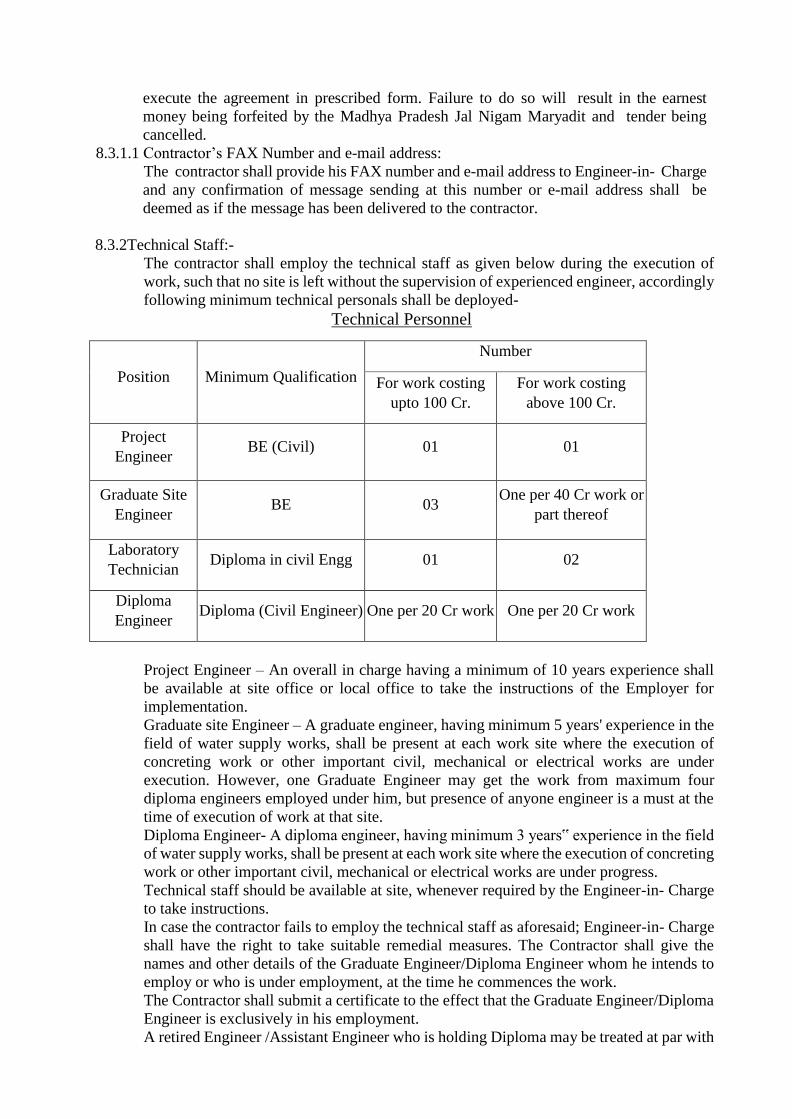
execute the agreement in prescribed form. Failure to do so will result in the earnest
money being forfeited by the Madhya Pradesh Jal Nigam Maryadit and tender being
cancelled.
8.3.1.1 Contractor’s FAX Number and e-mail address:
The contractor shall provide his FAX number and e-mail address to Engineer-in- Charge
and any confirmation of message sending at this number or e-mail address shall be
deemed as if the message has been delivered to the contractor.
8.3.2Technical Staff:-
The contractor shall employ the technical staff as given below during the execution of
work, such that no site is left without the supervision of experienced engineer, accordingly
following minimum technical personals shall be deployed-
Technical Personnel
Position Minimum Qualification
Number
For work costing
upto 100 Cr.
For work costing
above 100 Cr.
Project
Engineer BE (Civil) 01 01
Graduate Site
Engineer BE 03
One per 40 Cr work or
part thereof
Laboratory
Technician Diploma in civil Engg 01 02
Diploma
Engineer Diploma (Civil Engineer) One per 20 Cr work One per 20 Cr work
Project Engineer – An overall in charge having a minimum of 10 years experience shall
be available at site office or local office to take the instructions of the Employer for
implementation.
Graduate site Engineer – A graduate engineer, having minimum 5 years' experience in the
field of water supply works, shall be present at each work site where the execution of
concreting work or other important civil, mechanical or electrical works are under
execution. However, one Graduate Engineer may get the work from maximum four
diploma engineers employed under him, but presence of anyone engineer is a must at the
time of execution of work at that site.
Diploma Engineer- A diploma engineer, having minimum 3 years‟ experience in the field
of water supply works, shall be present at each work site where the execution of concreting
work or other important civil, mechanical or electrical works are under progress.
Technical staff should be available at site, whenever required by the Engineer-in- Charge
to take instructions.
In case the contractor fails to employ the technical staff as aforesaid; Engineer-in- Charge
shall have the right to take suitable remedial measures. The Contractor shall give the
names and other details of the Graduate Engineer/Diploma Engineer whom he intends to
employ or who is under employment, at the time he commences the work.
The Contractor shall submit a certificate to the effect that the Graduate Engineer/Diploma
Engineer is exclusively in his employment.
A retired Engineer /Assistant Engineer who is holding Diploma may be treated at par with

the Graduate Engineer.
Experienced non-engineer employee of the contractor may be considered at par as diploma
engineer after approval of the Engineer-in-Charge.
In case the contractor fails to employ the technical staff as aforesaid, he shall be liable to
pay to the Madhya Pradesh Jal Nigam Maryadit, a sum of INR 30,000/- (INR Thirty
Thousand) only for each of defaults, in case of Graduate Engineer and INR 20,000/- (INR
Twenty Thousand) only for each month in case of Diploma Engineer.
8.4 DELETED
8.5. Price Adjustment
8.5.1 Applicability
1. The price adjustment clause shall apply only for the works executed from the date of
start of work (21st day from LOA) until the end of the initial intended completion date
or extensions granted for reasons attributed to the Employer by the Engineer.
2. The Contractor shall not be entitled to any benefit arising from the price adjustment
clause for extension in the contract period for reasons attributed to the Contractor.
3. In the Force Majeure event the price escalation clause shall apply as given the Force
Majeure clause.
8.5.2 Procedure
Price Adjustment
The formula for adjustment of prices are:
R = Value of work as defined in Clause 31.1 of Conditions of Contract
Adjustment for Labour Component
(i) Price adjustment for increase or decrease in the cost due to labour shall be paid in
accordance with the following formula.
VL = 0.85 XP1/100 XR(Li – Lo ) / Lo
VL = increase or decrease in the cost of work during the month under consideration
due to changes in rates for local Labour.
Lo= the consumer price index for industrial workers for the State on 28days preceding
the date of opening of Technical Bids as published by Labour Bureau, Ministry of
Labour, Government of India.
Li= the consumer price index for industrial workers for the State for the month under
consideration as published by Labour Bureau, Ministry of Labour component of the
work.
P1 = Percentage of Labour component of the work.
Adjustment for Cement Component
(ii) Price adjustment for increase or decrease in the cost of cement procured by the
contractor shall be paid in accordance with the
following formula:
VC= 0.85 X PC/100 X R X(C1-C0)/C0
Vc= increase or decrease in the cost of work during the month under Consideration due
to changes in rates for cement.

Co= The all India wholesale price index for Pozzolana Cement on 28 days preceding the
date of opening of Technical Bids, as published by the Economic Advisor, DIPP,
Ministry of Commerce & Industry Government of India, New Delhi.
C1= The all India average wholesale price index for cement for the month under
consideration as published by the Economic Advisor, DIPP, Ministry of Commerce
& Industry Government of India, New Delhi.
Pc= Percentage of cement component of the work
Adjustment of Steel Component
(iii) Price adjustment for increase or decrease in the cost of steel procured by the
Contractor shall be paid in accordance with the following formula:
Vs= 0.85 X PS X /100 X R X (S1-S0)/S0
Vs= Increase or decrease in the cost of work during the month under consideration due
to changes in the rates for steel.
S0= The all India wholesale price index for mild steel long products / flats on 28 days
preceding the date of opening of Technical Bids, as published by the Economic
Advisor, DIPP, Ministry of Commerce & Industry Government of India, New Delhi.
Si = The all India average wholesale price index for mild steel long products / flats for the
month under consideration as published by the Economic Advisor, DIPP, Ministry of
Commerce & Industry Government of India, New Delhi.
Ps= Percentage of steel component of the work.
Note: For the application of this clause, index of mild steel long products / flats has been
Chosen to represent steel group. In any work only one of the indices i.e. either for
long products or for flats shall be used as decided by the Employer/ Executing
Agency.
Adjustment of HDPE/ Bitumin Component
(iv) Price Adjustment for increase or decrease is the cost of HDPE/bitumen shall be paid
in accordance with the following formula:
Vb= 0.85 X Pb / 100XRX( Bi – Bo) / Bo
Vb= Increase or decrease in the cost of work during the month under
consideration due to changes in rates for HDPE/ bitumen.
Bo = The official retail price of HDPE resin/bitumen at the IOC depot nearest to
the work site on the day 28 days prior to the date of opening ofTechnical
Bids.
Bi = The official retail price of HDPE resin /bitumen at the IOC depot nearest to
the work site for the 15th day of the month under consideration.
Pb= Percentage of HDPE/bitumen component of the work.
Adjustment of POL (Fuel and Lubricant) Component
( V) Price adjustment for increase or decrease in cost of POL (Fuel and Lubricant) shall
be paid in accordance with the following formula:
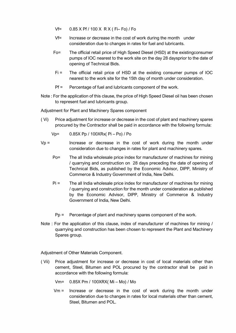
Vf= 0.85 X Pf / 100 X R X ( Fi– Fo) / Fo
Vf= Increase or decrease in the cost of work during the month under
consideration due to changes in rates for fuel and lubricants.
Fo= The official retail price of High Speed Diesel (HSD) at the existingconsumer
pumps of IOC nearest to the work site on the day 28 daysprior to the date of
opening of Technical Bids.
Fi = The official retail price of HSD at the existing consumer pumps of IOC
nearest to the work site for the 15th day of month under consideration.
Pf = Percentage of fuel and lubricants component of the work.
Note : For the application of this clause, the price of High Speed Diesel oil has been chosen
to represent fuel and lubricants group.
Adjustment for Plant and Machinery Spares component
( Vi) Price adjustment for increase or decrease in the cost of plant and machinery spares
procured by the Contractor shall be paid in accordance with the following formula:
Vp= 0.85X Pp / 100XRx( Pi – Po) / Po
Vp = Increase or decrease in the cost of work during the month under
consideration due to changes in rates for plant and machinery spares.
Po= The all India wholesale price index for manufacturer of machines for mining
/ quarrying and construction on 28 days preceding the date of opening of
Technical Bids, as published by the Economic Advisor, DIPP, Ministry of
Commerce & Industry Government of India, New Delhi.
Pi = The all India wholesale price index for manufacturer of machines for mining
/ quarrying and construction for the month under consideration as published
by the Economic Advisor, DIPP, Ministry of Commerce & Industry
Government of India, New Delhi.
Pp = Percentage of plant and machinery spares component of the work.
Note : For the application of this clause, index of manufacturer of machines for mining /
quarrying and construction has been chosen to represent the Plant and Machinery
Spares group.
Adjustment of Other Materials Component.
( Vii) Price adjustment for increase or decrease in cost of local materials other than
cement, Steel, Bitumen and POL procured by the contractor shall be paid in
accordance with the following formula:
Vm= 0.85X Pm / 100XRX( Mi – Mo) / Mo
Vm = Increase or decrease in the cost of work during the month under
consideration due to changes in rates for local materials other than cement,
Steel, Bitumen and POL.
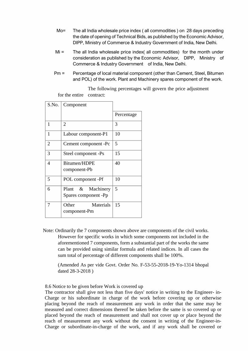
Mo= The all India wholesale price index ( all commodities ) on 28 days preceding
the date of opening of Technical Bids, as published by the Economic Advisor,
DIPP, Ministry of Commerce & Industry Government of India, New Delhi.
Mi = The all India wholesale price index( all commodities) for the month under
consideration as published by the Economic Advisor, DIPP, Ministry of
Commerce & Industry Government of India, New Delhi.
Pm = Percentage of local material component (other than Cement, Steel, Bitumen
and POL) of the work. Plant and Machinery spares component of the work.
The following percentages will govern the price adjustment
for the entire contract:
S.No. Component
Percentage
1 2 3
1 Labour component-P1 10
2 Cement component -Pc 5
3 Steel component -Ps 15
4 Bitumen/HDPE
component-Pb
40
5 POL component -Pf 10
6 Plant & Machinery
Spares component -Pp
5
7 Other Materials
component-Pm
15
Note: Ordinarily the 7 components shown above are components of the civil works.
However for specific works in which some components not included in the
aforementioned 7 components, form a substantial part of the works the same
can be provided using similar formula and related indices. In all cases the
sum total of percentage of different components shall be 100%.
(Amended As per vide Govt. Order No. F-53-55-2018-19-Yo-1314 bhopal
dated 28-3-2018 )
8.6 Notice to be given before Work is covered up
The contractor shall give not less than five days' notice in writing to the Engineer- in-
Charge or his subordinate in charge of the work before covering up or otherwise
placing beyond the reach of measurement any work in order that the same may be
measured and correct dimensions thereof be taken before the same is so covered up or
placed beyond the reach of measurement and shall not cover up or place beyond the
reach of measurement any work without the consent in writing of the Engineer-in-
Charge or subordinate-in-charge of the work, and if any work shall be covered or
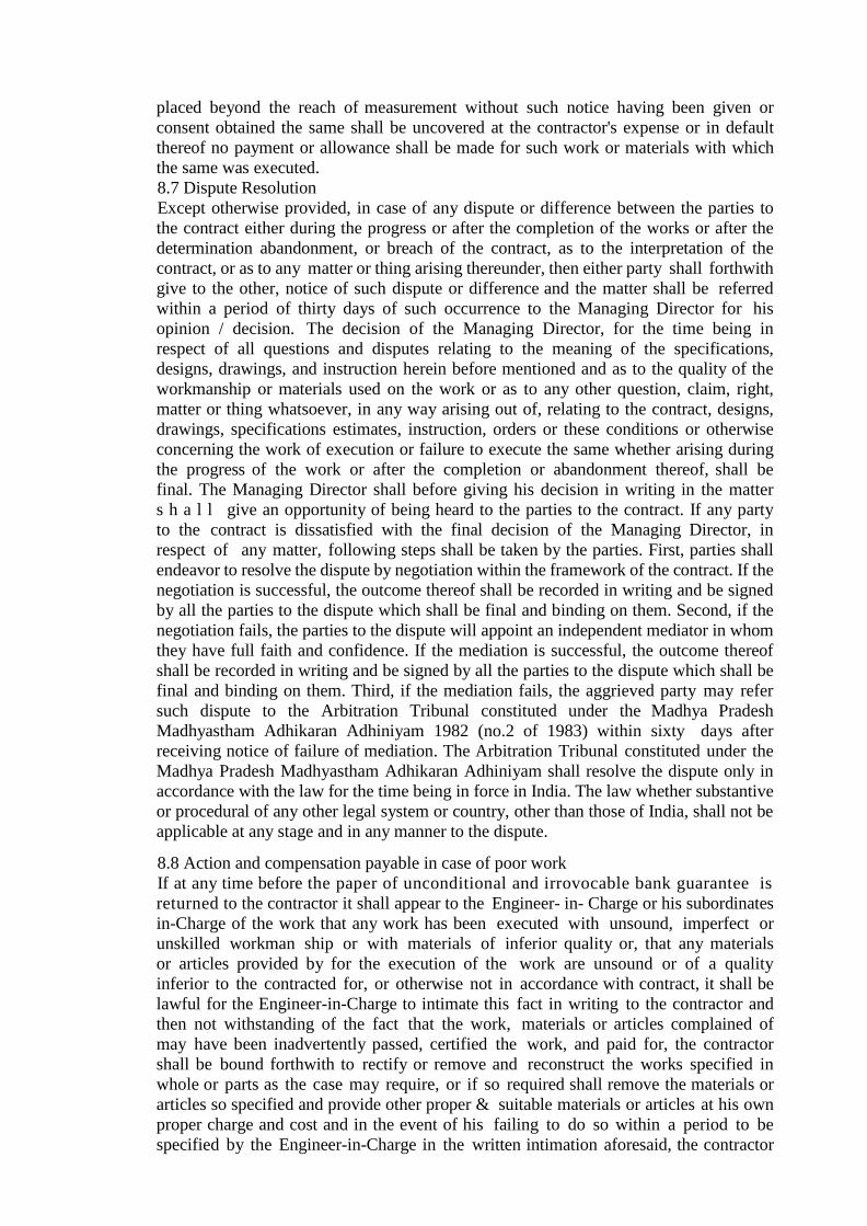
placed beyond the reach of measurement without such notice having been given or
consent obtained the same shall be uncovered at the contractor's expense or in default
thereof no payment or allowance shall be made for such work or materials with which
the same was executed.
8.7 Dispute Resolution
Except otherwise provided, in case of any dispute or difference between the parties to
the contract either during the progress or after the completion of the works or after the
determination abandonment, or breach of the contract, as to the interpretation of the
contract, or as to any matter or thing arising thereunder, then either party shall forthwith
give to the other, notice of such dispute or difference and the matter shall be referred
within a period of thirty days of such occurrence to the Managing Director for his
opinion / decision. The decision of the Managing Director, for the time being in
respect of all questions and disputes relating to the meaning of the specifications,
designs, drawings, and instruction herein before mentioned and as to the quality of the
workmanship or materials used on the work or as to any other question, claim, right,
matter or thing whatsoever, in any way arising out of, relating to the contract, designs,
drawings, specifications estimates, instruction, orders or these conditions or otherwise
concerning the work of execution or failure to execute the same whether arising during
the progress of the work or after the completion or abandonment thereof, shall be
final. The Managing Director shall before giving his decision in writing in the matter
s h a l l give an opportunity of being heard to the parties to the contract. If any party
to the contract is dissatisfied with the final decision of the Managing Director, in
respect of any matter, following steps shall be taken by the parties. First, parties shall
endeavor to resolve the dispute by negotiation within the framework of the contract. If the
negotiation is successful, the outcome thereof shall be recorded in writing and be signed
by all the parties to the dispute which shall be final and binding on them. Second, if the
negotiation fails, the parties to the dispute will appoint an independent mediator in whom
they have full faith and confidence. If the mediation is successful, the outcome thereof
shall be recorded in writing and be signed by all the parties to the dispute which shall be
final and binding on them. Third, if the mediation fails, the aggrieved party may refer
such dispute to the Arbitration Tribunal constituted under the Madhya Pradesh
Madhyastham Adhikaran Adhiniyam 1982 (no.2 of 1983) within sixty days after
receiving notice of failure of mediation. The Arbitration Tribunal constituted under the
Madhya Pradesh Madhyastham Adhikaran Adhiniyam shall resolve the dispute only in
accordance with the law for the time being in force in India. The law whether substantive
or procedural of any other legal system or country, other than those of India, shall not be
applicable at any stage and in any manner to the dispute.
8.8 Action and compensation payable in case of poor work
If at any time before the paper of unconditional and irrovocable bank guarantee is
returned to the contractor it shall appear to the Engineer- in- Charge or his subordinates
in-Charge of the work that any work has been executed with unsound, imperfect or
unskilled workman ship or with materials of inferior quality or, that any materials
or articles provided by for the execution of the work are unsound or of a quality
inferior to the contracted for, or otherwise not in accordance with contract, it shall be
lawful for the Engineer-in-Charge to intimate this fact in writing to the contractor and
then not withstanding of the fact that the work, materials or articles complained of
may have been inadvertently passed, certified the work, and paid for, the contractor
shall be bound forthwith to rectify or remove and reconstruct the works specified in
whole or parts as the case may require, or if so required shall remove the materials or
articles so specified and provide other proper & suitable materials or articles at his own
proper charge and cost and in the event of his failing to do so within a period to be
specified by the Engineer-in-Charge in the written intimation aforesaid, the contractor
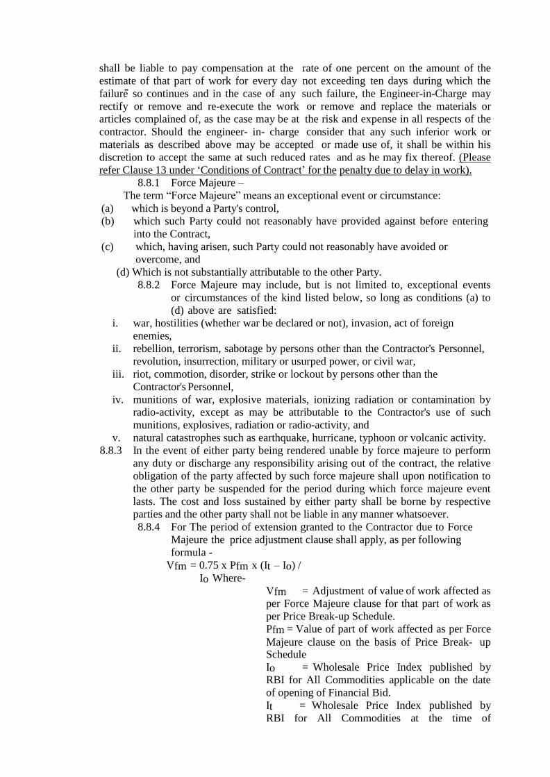
shall be liable to pay compensation at the rate of one percent on the amount of the
estimate of that part of work for every day not exceeding ten days during which the
failure so continues and in the case of any such failure, the Engineer-in-Charge may
rectify or remove and re-execute the work or remove and replace the materials or
articles complained of, as the case may be at the risk and expense in all respects of the
contractor. Should the engineer- in- charge consider that any such inferior work or
materials as described above may be accepted or made use of, it shall be within his
discretion to accept the same at such reduced rates and as he may fix thereof. (Please
refer Clause 13 under ‘Conditions of Contract’ for the penalty due to delay in work).
8.8.1 Force Majeure –
The term “Force Majeure” means an exceptional event or circumstance:
(a) which is beyond a Party's control,
(b) which such Party could not reasonably have provided against before entering
into the Contract,
(c) which, having arisen, such Party could not reasonably have avoided or
overcome, and
(d) Which is not substantially attributable to the other Party.
8.8.2 Force Majeure may include, but is not limited to, exceptional events
or circumstances of the kind listed below, so long as conditions (a) to
(d) above are satisfied:
i. war, hostilities (whether war be declared or not), invasion, act of foreign
enemies,
ii. rebellion, terrorism, sabotage by persons other than the Contractor's Personnel,
revolution, insurrection, military or usurped power, or civil war,
iii. riot, commotion, disorder, strike or lockout by persons other than the
Contractor's Personnel,
iv. munitions of war, explosive materials, ionizing radiation or contamination by
radio-activity, except as may be attributable to the Contractor's use of such
munitions, explosives, radiation or radio-activity, and
v. natural catastrophes such as earthquake, hurricane, typhoon or volcanic activity.
8.8.3 In the event of either party being rendered unable by force majeure to perform
any duty or discharge any responsibility arising out of the contract, the relative
obligation of the party affected by such force majeure shall upon notification to
the other party be suspended for the period during which force majeure event
lasts. The cost and loss sustained by either party shall be borne by respective
parties and the other party shall not be liable in any manner whatsoever.
8.8.4 For The period of extension granted to the Contractor due to Force
Majeure the price adjustment clause shall apply, as per following
formula -
Vfm = 0.75 x Pfm x (It – Io) /
Io Where-
Vfm = Adjustment of value of work affected as
per Force Majeure clause for that part of work as
per Price Break-up Schedule.
Pfm = Value of part of work affected as per Force
Majeure clause on the basis of Price Break- up Schedule
Io = Wholesale Price Index published by
RBI for All Commodities applicable on the date
of opening of Financial Bid.
It = Wholesale Price Index published by
RBI for All Commodities at the time of
consideration.
Note- However, if there is any delay in acquisition of land as per Para 19, Part – I of
NIT, the Employer shall give possession of the whole Site or such parts of the Site
as are sufficient to enable the Contractor to commence and proceed with the
execution of the Works in accordance with the approved Work Program and
possession of such further portions of the Site as may be required to enable
Contractor to proceed with the execution of the Works with due diligence in
accordance with the agreed program or proposals, as the case may be shall be
provided to the Contractor. In the event of non-possession of site as per
Contractor’s program arises the Contractor will reschedule his program according
to availability of site. If the Employer fails to give possession of the whole or
part of the Site to the contractor in accordance with above provisions, the Employer
is deemed to have delayed the start of the relevant activities and this shall be
considered for price escalation.
8.8.5 The time for performance of the relative obligation suspended by the force
majeure shall stand extended by the period for which such cause lasts. Should the
delay caused by force majeure exceed twelve months, the parties to the contract
shall be at liberty to foreclose the contract after holding mutual discussions.
8.9 Extension of Time:
If the contractor shall desire an extension of the time for completion of the work on the grounds of his having been unavoidably hindered in its execution or any other ground,
he shall apply in writing to the Engineer-in-Charge of PIU and the Officer, with whom he has signed the agreement. The Engineer-in-Charge shall, if in his opinion, (which
shall be final) find reasonable grounds, are shown therefore, may authorize such extension for such period as is reasonably necessary under the circumstances. Any
further extension of time shall be subjected to the previous sanction of the Managing Director (grounds to be shown therefore, for which a register will be maintained for the
occurrence of the hindrances and its resolution, which will be duly signed by the
contractor and the Engineer-in-charge.
i) The contract is for completion of works and therefore non approval of EOT shall not
in any way invalidate the contract. The contractor will have to complete the works.
ii) In the event of delays attributable to the contractor, the EOT shall not be given by
the Engineer-in-Charge and the Liquidated Damages shall be levied from the
contractor in accordance with the provisions of the contract.
iii) In the event, the delays are not attributable to the contractor the EOT may be issued
by the Engineer-in-Charge without imposition of Liquidated Damages either suo-
motto or on a written request of the contractor.
It is clarified that out of the total delays in completion of works, the EOT shall be
issued only for the part, which is not attributable to the contractor.
(Amended as per Govt. Order No. F-53-55-2018-19-Yo-1154 bhopal, dated 23-03-2018)
8.10 Defect Liability Period:
The defect liability period in respect of the entire structure as a whole or in parts of
individual components included in the contract shall be upto the end of Operation and
Maintenance period after successful completion of work in all respects and its testing &
commissioning
8.10.1 Contractor liable for damage done and for imperfection for the period
upto the end of Operation and Maintenance after completion certificate:
If the contractor or his work people, or servants shall break, deface, injure or destroy
any part of the building in which they may be working or any building, road, road
curbs, fences, enclosures, water pipe, cables, drains, electric or telephone posts or
wires, trees, grass or grass land or cultivated ground contiguous to the premises on
which the work or any part of it is being executed, or if any damage shall happen to the
work while in progress, from any cause whatsoever, or any imperfections become
apparent in it, within the Operation and Maintenance period after a certificate, final or
otherwise of its completion shall have been given by the Engineer-in- Charge as
aforesaid, the contractor shall make the same good at his own expenses or in default
the Engineer- in-Charge may cause the same to be made good by other workmen and
deduct the expenses (of which the certificate of the Engineer-in-Charge shall be final)
from any sums that may be then or any times thereafter may become due to the
contractor or from his security deposit or the proceed of sale thereof or of sufficient
portion thereof.
8.11 Action when the work is left Incomplete, Abandoned or Delayed beyond the
Permitted Limit allowed by the Engineer-in-Charge:
If the Contractor fails to carry out any obligation under the Contract, the Engineer in
Charge may by notice require the Contractor to make good the failure and to remedy it
within a specified reasonable time.
8.11.1 The Engineer in Charge shall be entitled to terminate the Contract if the Contractor
a) abandons the Works or otherwise plainly or otherwise demonstrates the intention not
to continue performance of his obligations under the Contract;
b) the Contractor is declared as bankrupt or goes into liquidation other than for approved
reconstruction or amalgamation;
c) without reasonable excuse fails to comply with the notice to correct a particular defect
within a reasonable period of time;
d) the Contractor does not maintain a valid instrument of bank guarantee and financial
security as prescribed;
e) the Contractor has delayed the completion of the Works by such duration for which
the maximum amount of liquidated damages is recoverable;
f) If the Contractor fails to deploy machinery and equipment or personnel or set up a field
laboratory as specified in the Contract Data;
g) If the contractor, in the judgment of the Engineer in charge has engaged in corrupt or
fraudulent practices in competing for or in executing the contract;
h) Any other act amounting to breach of contract including fundamental breaches, and
breach of fundamental terms.
In any of these events or circumstances, the Engineer in Charge may, upon giving 14
days’ notice to the Contractor, terminate the Contract and expel the Contractor from the
Site. However, in the case of sub-paragraph (b) or (g) of clause 8.11, the Engineer in
Charge may terminate the Contract immediately.
8.11.2 Notwithstanding anything contained in the above clause, the Engineer-in-Charge may
terminate the Contract for convenience by giving notice to the Contractor.
8.11.3 Payment upon Termination: If the contract is terminated under clause 8.11.1, the Engineer shall issue a certificate for
value of the work done less advance payments received upto the date of issue of the
certificate, less other recoveries due in terms of the contract, less taxes due to be deducted
at source as per applicable law and less the percentage to apply to the value of work not
completed (10%).In the event of contract being terminated (during execution or during
O&M period), under clause 8.11.1, the amount of security deposit (remaining at that
point) of the contractor will be forfeited.
8.11.4 Payment on termination under clause 8.11.2 above
If the Contract is terminated under clause 8.11.2 above, the Engineer shall issue a
certificate for the value of the work done, the reasonable cost of removal of Equipment,
repatriation of the Contractor's personnel employed solely on the Works, and the
Contractor's costs of protecting and securing the Works and less advance payments
received up to the date of the certificate, less other recoveries due in terms of the contract
and less taxes due to be deducted at source as per applicable law. If the total amount due
to the Employer exceeds any payment due to the Contractor, the difference shall be
recovered as per clause 8.11 above.
8.12 Legal Jurisdiction -
Arbitration shall always remain the primary method of resolution of dispute relating to or
arising out of this contract. Judicial proceedings shall not be an alternative for arbitration.
Subject to the provisions of the clause relating to Dispute Resolution, the Commercial
Court, Bhopal or the Commercial Division at the High Court of Madhya Pradesh,
Jabalpur, as the case may be, constituted under the provisions of the Commercial Courts,
Commercial Division and Commercial Appellate Division of High Courts Act, 2015
shall have the exclusive jurisdiction relating to all the disputes r e l a t i n g t o a n d
regarding this contract. No other Courts in India or in any other legal system or
country shall have the original jurisdiction. The Commercial Court, Bhopal or the
Commercial Division at the High Court of Madhya Pradesh, Jabalpur shall apply only
the laws for time being in force in India. The law, whether substantive law or procedural
law, of any other legal system or country, other than those of India, shall have
no application to this contract or to the dispute arising out of this contract. .
8.13 Conditions applicable for contract:
All the conditions of the tender notice shall be binding on the contractors and the
Employer in addition to the conditions of the contract in the prescribed form.
9. Bid Evaluation-
The tendered cost of each bidder shall be evaluated as below-
Effective Lump Sum Offer of the bidder = L + {CCB - CCL} Where-
L = Lump sum Cost offered by the bidder
CCB = Capitalized cost of energy charges Cc of the bidder CCL = Capitalized cost of energy charges Cc of the lowest
technically responsive bidder.
10. Following documents annexed with this N.I.T. shall form part of the
contract.
ANNEXURE – 1 : Joint Venture
ANNEXURE – 2 : Affidavit
ANNEXURE 'A' : Model rules, relating to labor water
supply sanitation etc.
ANNEXURE 'B' : Contractor's labor regulations.
ANNEXURE 'D' : Form of Income Tax Clearance
Certificate.
ANNEXURE 'E' : Specifications
ANNEXURE 'F' : Schedule of main items of work & leading
details
APPENDIX-1 : List of Villages and Water Demand
ANNEXURE 'H' : Break-up schedule of payment.
ANNEXURE 'I' : Drawings.
Managing Director
Madhya Pradesh Jal Nigam Maryadit
Vindhyachal Bhawan, Bhopal
MADHYA PRADESH JAL NIGAM MARYADIT
(A GOVT. OF M.P. UNDERTAKING)
TENDER FOR A LUMP SUM CONTRACT
FORM ‘F’
I /We do hereby tender to execute the whole of the work described in the drawing
Nos.………………… and according to the annexed specification as signed by
…………….. by………………….. and dated ……………… for the sum of
IN R……………………. and should this tender be accepted I / we do hereby agree and bind
myself/ourselves to abide by and fulfill all the conditions annexed to the said specification or
in default thereof to forfeit and pay to the Madhya Pradesh Jal Nigam Maryadit the penalties

of sums of money mentioned in the said conditions.
Dated …………………. Tenderer’s Signature………………………………….
Address……………………………………………….
Witness……………………….. Address………………………..
The above tender is hereby accepted by me on behalf of the Madhya Pradesh Jal Nigam
Maryadit.
The ………………….2018………….. Signature of authority by
which the tender is accepted
* To be expressed in words and figures.
SECURITIES
Name Address Occupation or Profession Remarks
CONDITIONS OF CONTRACT
1. The person(s) whose tender may be accepted hereinafter called the contractor(s)
shall within twenty days of the receipt by him/them of the notification of the
acceptance of his/their tender execute an unconditional and irrovocable bank
guarantee in favor of the Employer ( Managing Director, Madhya Pradesh Jal Nigam
Maryadit) for a sum equal to the percent of the sum specified in the clause 3.5 of
Detailed Notice Inviting Tender, for a period on the basis of condition for refund
of Security Deposit (Para 3.5). All damages to be borne, or other sums of money
payable by the contractor(s) to the Madhya Pradesh Jal Nigam Maryadit under the
terms of this contract may be deducted from the running bill or from any sums
which may be due or may become due to the contractors by the Madhya Pradesh
Jal Nigam Maryadit on any account whatsoever. The Employer shall be entitled to
get the bank guarantee encashed if in his opinion the contractor has committed the
breach of contract.
The Contractor(s) shall provide everything of every sort and kind (with the
exception noted in the schedule attached) which may be necessary and requisite for
the due and proper execution of the several works included in the contract according
to the true intent and meaning of the drawings and specification taken together,
which are to be signed by General Manager of PIU, (hereinafter called the
Engineer-in-Charge) and the contractor(s) whether the same may or may not be
particularly described in the specification or shown on the drawing; provided that the
same are reasonably and obviously to be inferred therefrom and in case of any
discrepancy between the drawings and the specification the Engineer-in-Charge is to
decide which shall be followed.
2. The contractor(s) shall set out the whole of the works in conjunction with an officer to be deputed by the M.D. and during the progress of the works to amend on
the requisition of the Engineer-in-Charge any errors which may arise therein and provide all the necessary labor and materials for so doing. The contractor(s) shall
provide all plant, labor and materials (with the exception noted in the schedule
attached) which may be necessary and requisite for the works. All materials and workmanship are to be the best of their respective kinds and must meet the standard
of the state of art. The contractor(s) shall handover all the work in all respects clean and perfect at the completion thereof.
3.
2(A) In respect of all bearings, hinges or similar parts intended for use in the
superstructure of any bridge, the contractor shall, whenever required, in the course
of manufacture, arrange and afford all the necessary and adequate facilities for the
purpose of inspections and tests of all or any of these parts and the material used
therein to any officer of the Directorate of Inspection of the Ministry of Works,
Production and supply of the Government of India and such bearings, hinges or
similar parts shall not be used in the superstructure of any bridge except on
production of a certificate of acceptance thereof from the Directorate of Inspection.
All inspection charges will be payable by the contractor.
4. Complete copies of the drawings and specification signed by the Engineer-in- Charge
shall be furnished by him to the contractor(s) for his/their own use and the same or
copies thereof are to be kept on buildings in-charge of the contractor's (s‟) agent who
is to be constantly kept on the ground by the contractor(s) and to whom the
instructions can be given by the Engineer-in-Charge. The contractor's shall not to
sublet the works or any part thereof without the consent in writing of the Engineer-
in-Charge.
5. The Engineer-in-Charge is to have at all times access to the works which are to be
entirely under his control. He may require the contractor(s) dismiss any person in the
contractor(s) employ upon the works who may be incompetent or misconduct
himself and the contractor(s) shall forthwith comply with such requirements.
6. The contractor(s) shall not alter, vary or deviate from the approved drawings or
specifications or execute any extra work of any kind, whatsoever. In case of daily
labor all vouchers for the same shall be delivered to the Engineer-in-Charge or the
officer in charge at-least during the week following that in which the work may have
been done and only such day work is to be allowed for as such as may have been
authorized by the Engineer-in-Charge to be so done, unless the work cannot from
its character be properly measured and valued.
7. Any authority given by the Engineer-in-Charge for any alternations or additions in
or to works is not to vitiate the contract, but all additions, omission or variations
made in carrying out the work are to be measured and valued and certified by the
Engineer-in-Charge and added to or deducted from the amount of the contract as
the case may be at rates in force in the Latest Schedule of Rates of Urban
Administration and Development Department/P.H.E. Department, as specified. In
such cases in which rates do not exist, the Managing Director will fix the rates to be
paid, whose decision shall be final and binding.
8. All works and materials brought and left upon the ground by the contractor(s) or
his/their orders for the purpose of forming part of the works shall be considered to be
the property of the Madhya Pradesh Jal Nigam Maryadit and the same shall not to be
removed or taken away by the Contractor(s) or any other person without the
special license and consent in writing of the Engineer-in-Charge but the Madhya
Pradesh Jal Nigam Maryadit shall not to be in any way answerable for any loss
or damage which may happen to or in respect of any such work or materials either
by the same being lost or stolen or injured by weather or otherwise.
9. The Engineer-in-Charge shall have the full power to require the removal from the premises of all materials which in his opinion, are not in accordance with the
specification and in case of defaults the Engineer-in-Charge shall be at liberty to employ other persons to remove the same without being answerable or accountable
for any loss or damage that may happen or arise to such materials. The Engineer-in-Charge shall also have t he full power to require other proper materials to be
substituted and in case of default the Engineer-in-Charge may cause the same to be
supplied and all costs which may attend such removal and substitution are to be borne by the contractor(s).
10. If in the opinion of the Engineer-in-Charge any of the work, is executed with
improper materials or defective workmanship, the contractor(s) shall, when
directed by the Engineer-in-Charge, forth with re-execute the same and substitute
proper materials and workmanship and in case of default of the contractor(s) in so
doing within a week the Engineer-in-Charge shall have the full power to employ
other persons to re-execute the work and the cost thereof shall be borne by the
contractor(s).
11. Any defects, shrinkage or other faults which may appear within Defect Liability
Period from the completion of the project arising out of defective or improper
materials or workmanship shall upon the direction of the Engineer-in-Charge to be
amended and made good by the contractor(s) at his/their own cost unless the
Engineer-in-Charge shall decide that he/they ought to be paid for the same and in
case of default the Madhya Pradesh Jal Nigam Maryadit may recover from the
contractors the cost or making good the works.
12. From the commencement of the works to the completion of the same, they are to be
under the contractors(s) charge. The contractor(s) shall be held responsible for and to
make good all injuries, damage and repairs occasioned or rendered necessary to
the same by fire or other causes and they are to hold the Madhya Pradesh Jal
Nigam Maryadit harmless from any claims for injuries to persons or for structure
damage to property happening from any neglect, default, want of proper care or
misconduct on the part of the contractor(s) or of any one in his/their employ during
the execution of the works.
13. The Engineer-in-Charge shall have the full power to send workmen upon the
premises to exceeded fittings and other works not included in the contract for whose
operations the contractor(s) shall afford every reasonable facility during ordinary
working hours, provided that such operations shall be carried on in such a manner
as not to impede the progress of the work included in the contract but the
contractor(s) shall not to be responsible for any damage which may happen to or be
occasioned by any such fittings or other works.
14. The works comprised in this tender are to be commenced immediately upon receipt
of the order of commencement given in writing by the Engineer-in-Charge when
possession of the site can be had, the whole work including all such additions and
variations as aforesaid (But excluding such, if any, as may have been postponed by
an order from the Engineer-in-Charge) shall be completed in every respect within
30 months including rainy season from the date of issue of the aforesaid order and
if from any cause whatever other than willful obstruction or default on the part of
the Engineer-in-Charge or his staff and except as hereinafter provided the whole of
such work shall not be finished to the satisfaction of the Engineer-in-Charge within
the said period, the contractor(s) shall forfeit to the Madhya Pradesh Jal Nigam
Maryadit from his/their bills, and/or encash the bank guarantee, and/or recover
liquidated damages for each default @ 0.05 % per day.
The above liquidated damages shall be applicable for every completed day of such
default provided that the entire amount of damages to be forfeited under the
provisions of the clause shall not exceed ten percent on the quoted cost of the
whole work as shown in the tender.
Nevertheless and in case of any extension of time, the aforesaid provisions with
amount for damages in defaults of due completion shall apply in case of non-
completion of the works within the extended time. Provided that the contractors(s)
shall not be entitled to any extension of time in respect of the extra work involved
in the extra depth of foundation mentioned in clause (5).
15. If the Contractor(s) shall become bankrupt or compound with or make any
assignment for the benefit of his/their creditors or shall suspend or delay the
performance of his/their part of the contract (except on account of causes mentioned
in clause 13 or in consequence of not having proper instructions for which one
contractor(s) shall have duly applied). The Engineer-in-Charge may give to the
contractor(s) or his/their assignee or trustee, as the case may be notice requiring the
work to be proceeded with and in case of default on the part of the contractor(s) or
his/their assignee or trustee for a period of seven days. It shall be lawful for the
Engineer-in-Charge to enter upon and take possession of the works and employ any
other persons to carry on and complete the same and to authorize him or them to
use the plant, materials and property of the contractor(s) upon the works, and the
costs and charges incurred in any way in carrying on and completion the said works
are to be paid to the Managing Director by the Contractor(s). The Managing
Director shall be t h e final authority to determine the amount spent to complete
the unfinished work. The certificate of Engineer-in-Charge and approved by
Managing Director as the value of the balance work done shall be final and binding
on the contractor.
16. The contractor(s) shall be paid on the completion of each calendar month
commencing from the date of work order, a sum equal to the total value of work
done in accordance with Annexure ''H'' (Price Break Up Schedule) since the last
payment according to the certificate of the Engineer-in-Charge. When the works
shall be completed the contractor(s) shall be entitled to receive one moiety of
the amount remaining due according to the best estimate of the same that can be
made and the contractor(s) shall be entitled to receive the balance of all moneys
due or payable to him/them under or by virtue of the contract within six months
from the completion of the works provided always that no final or other certificate
is to cover or relieve the contractor(s) from his/their liability under the provision
of clause 10 whether or not the same be notified by the Engineer-in-Charge at
the time or subsequently to the granting of any such certificate.
17. A certificate of the Engineer-in-Charge or an award of the referee hereinafter referred
to, as the case may be, showing the final balance due or payable to the
contractor(s) shall be conclusive evidence of the works having been duly completed
and that the contractor(s) shall be entitled to receive payment of the final balance
but without prejudice of the liability of the contractor(s) under provision of clause
10.
18. Provided that in case of any question/dispute of difference arising between the
Engineer-in-Charge and the Contractor(s) as to what additions if any, ought in
fairness to be made to the amount of the contract by reason of the works being
delayed through no fault of the contractor(s) or by reason or on account of any
directions of requisitions of the Engineer-in-Charge involving increased cost of the
contractor(s) beyond the cost properly attending the carrying out of the contract
according to the true intent and meaning of the signed drawings and specifications
or as to the works having been duly completed or as to the construction of these
presents or as to any other matter or thing arising under or out of this contract,
except as to matters, left during the progress of the works to the sole decision or
requisition of the Engineer-in-Charge under clauses No. 1,4,8 & 9 or in case the
contractor(s) shall be dissatisfied with any certificate of the Engineer-in-Charge
under clause 6 or under the provision in clause 13 of in case he shall withhold or
not give any certificate to which he/they may be entitled or as to the right of the
contractor's to receive any compensation or as to the amount of such compensation
payable to him/them under clause 18, then such question, dispute or difference or
such certificate of the value or matter which should be certified, as the case may be
is to be from time to time reso lved as detailed in Clause 8.6..
19. If at any time before or after the commencement of the work, Madhya Pradesh Jal
Nigam Maryadit shall, for any reason whatsoever :-
i. Causes alterations, omissions or variation in the drawings and specification
involving any curtailment of the works as originally contemplated; or
ii. Does Not require the whole of work as specified in the tender to be carried out,
the contractor(s) shall have no claim to any payment or compensation whatsoever
on the account of any profit or advantage which he/ they may have derived from
the execution of the work in full as specified in the tender but which he/they did
not derive in consequence of the curtailment of the works by reason of
alterations, omissions or variations or in consequence of the full amount of the work
not having being carried out.
But the contractor(s) shall be entitled to compensation for any loss sustained by
him/ them by reason of his/their having purchased or procured any materials or
h a v i n g entered into any engagements or having made any advances to labour

or having taken any other preliminary or incidental measures on account of or with
a view to the execution of the works or the performance of the contract.
Signature of the Contractor Managing Director
Madhya Pradesh Jal Nigam
Maryadit Vindhyachal
Bhawan, Bhopal
Dated……… Dated…………
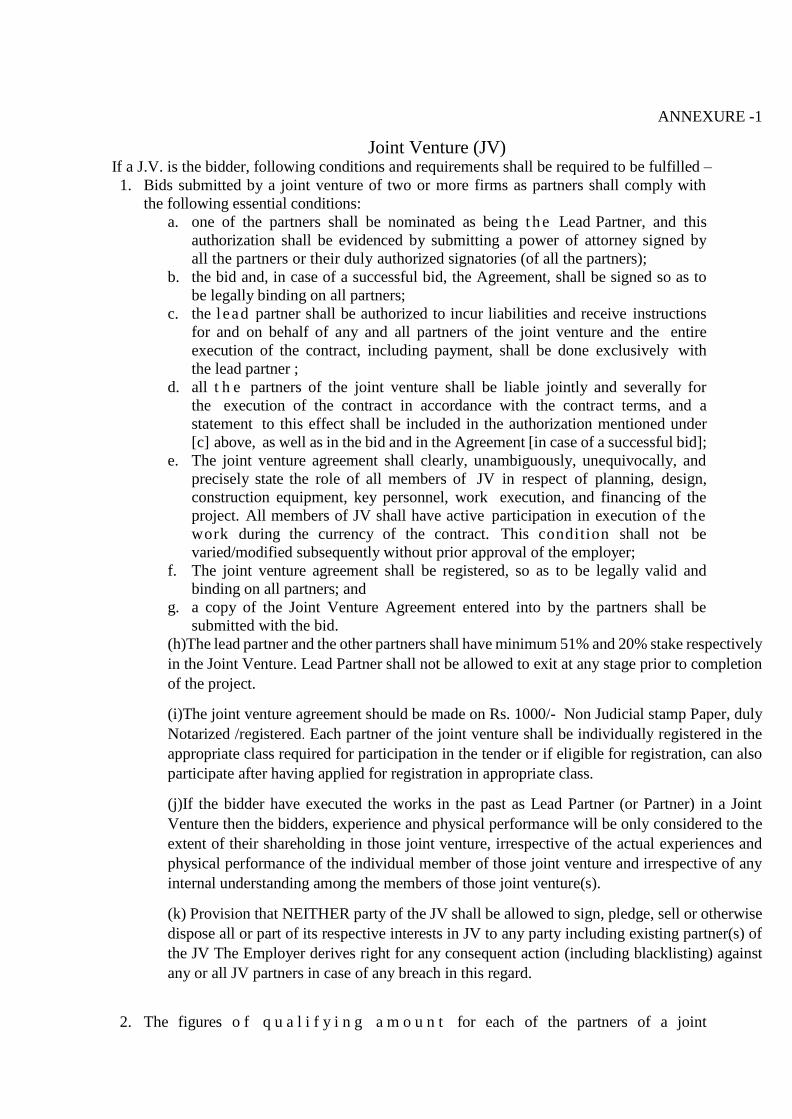
ANNEXURE -1
Joint Venture (JV) If a J.V. is the bidder, following conditions and requirements shall be required to be fulfilled –
1. Bids submitted by a joint venture of two or more firms as partners shall comply with
the following essential conditions:
a. one of the partners shall be nominated as being t h e Lead Partner, and this
authorization shall be evidenced by submitting a power of attorney signed by
all the partners or their duly authorized signatories (of all the partners);
b. the bid and, in case of a successful bid, the Agreement, shall be signed so as to
be legally binding on all partners;
c. the l ead partner shall be authorized to incur liabilities and receive instructions
for and on behalf of any and all partners of the joint venture and the entire
execution of the contract, including payment, shall be done exclusively with
the lead partner ;
d. all t h e partners of the joint venture shall be liable jointly and severally for
the execution of the contract in accordance with the contract terms, and a
statement to this effect shall be included in the authorization mentioned under
[c] above, as well as in the bid and in the Agreement [in case of a successful bid];
e. The joint venture agreement shall clearly, unambiguously, unequivocally, and
precisely state the role of all members of JV in respect of planning, design,
construction equipment, key personnel, work execution, and financing of the
project. All members of JV shall have active participation in execution of the
work during the currency of the contract. This condition shall not be
varied/modified subsequently without prior approval of the employer;
f. The joint venture agreement shall be registered, so as to be legally valid and
binding on all partners; and
g. a copy of the Joint Venture Agreement entered into by the partners shall be
submitted with the bid.
(h)The lead partner and the other partners shall have minimum 51% and 20% stake respectively
in the Joint Venture. Lead Partner shall not be allowed to exit at any stage prior to completion
of the project.
(i)The joint venture agreement should be made on Rs. 1000/- Non Judicial stamp Paper, duly
Notarized /registered. Each partner of the joint venture shall be individually registered in the
appropriate class required for participation in the tender or if eligible for registration, can also
participate after having applied for registration in appropriate class.
(j)If the bidder have executed the works in the past as Lead Partner (or Partner) in a Joint
Venture then the bidders, experience and physical performance will be only considered to the
extent of their shareholding in those joint venture, irrespective of the actual experiences and
physical performance of the individual member of those joint venture and irrespective of any
internal understanding among the members of those joint venture(s).
(k) Provision that NEITHER party of the JV shall be allowed to sign, pledge, sell or otherwise
dispose all or part of its respective interests in JV to any party including existing partner(s) of
the JV The Employer derives right for any consequent action (including blacklisting) against
any or all JV partners in case of any breach in this regard.
2. The figures o f q u a l i f y i n g a m o u n t for each of the partners of a joint
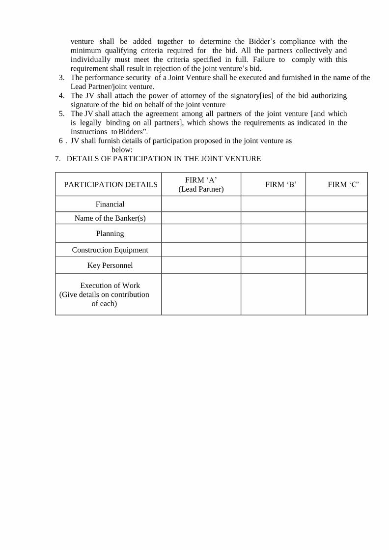
venture shall be added together to determine the Bidder’s compliance with the
minimum qualifying criteria required for the bid. All the partners collectively and
individually must meet the criteria specified in full. Failure to comply with this
requirement shall result in rejection of the joint venture’s bid.
3. The performance security of a Joint Venture shall be executed and furnished in the name of the
Lead Partner/joint venture.
4. The JV shall attach the power of attorney of the signatory[ies] of the bid authorizing
signature of the bid on behalf of the joint venture
5. The JV shall attach the agreement among all partners of the joint venture [and which
is legally binding on all partners], which shows the requirements as indicated in the
Instructions to Bidders‟.
6 . JV shall furnish details of participation proposed in the joint venture as
below:
7. DETAILS OF PARTICIPATION IN THE JOINT VENTURE
PARTICIPATION DETAILS FIRM ‘A’
(Lead Partner) FIRM ‘B’ FIRM ‘C’
Financial
Name of the Banker(s)
Planning
Construction Equipment
Key Personnel
Execution of Work
(Give details on contribution
of each)
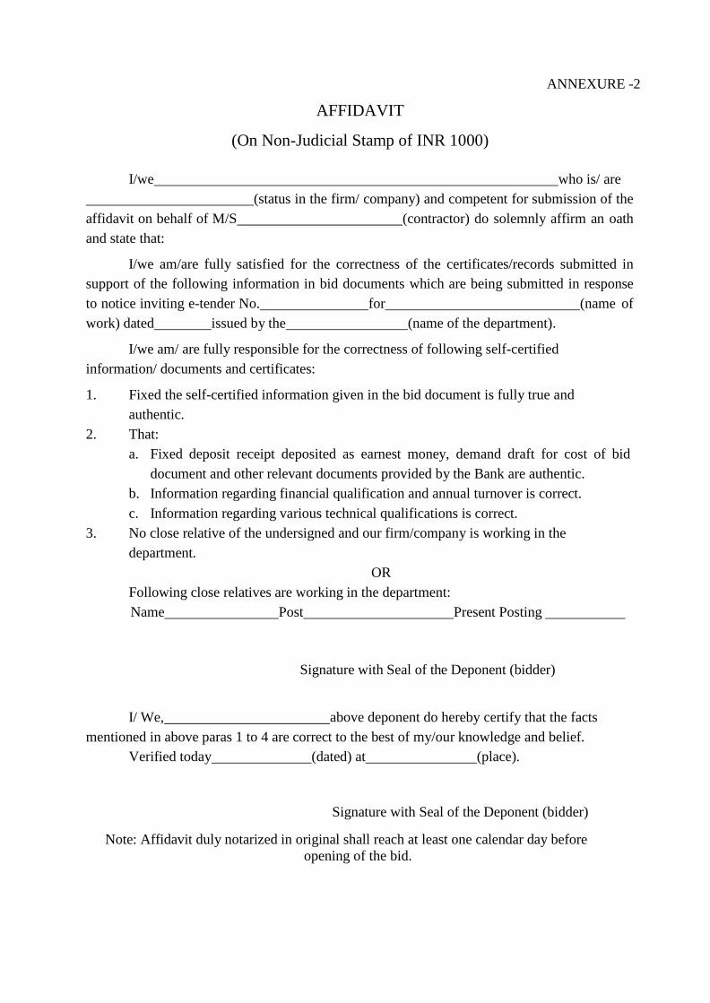
ANNEXURE -2
AFFIDAVIT
(On Non-Judicial Stamp of INR 1000)
I/we who is/ are
(status in the firm/ company) and competent for submission of the
affidavit on behalf of M/S (contractor) do solemnly affirm an oath
and state that:
I/we am/are fully satisfied for the correctness of the certificates/records submitted in
support of the following information in bid documents which are being submitted in response
to notice inviting e-tender No. for (name of
work) dated issued by the (name of the department).
I/we am/ are fully responsible for the correctness of following self-certified
information/ documents and certificates:
1. Fixed the self-certified information given in the bid document is fully true and
authentic.
2. That:
a. Fixed deposit receipt deposited as earnest money, demand draft for cost of bid
document and other relevant documents provided by the Bank are authentic.
b. Information regarding financial qualification and annual turnover is correct.
c. Information regarding various technical qualifications is correct.
3. No close relative of the undersigned and our firm/company is working in the
department.
OR
Following close relatives are working in the department:
Name Post Present Posting
Signature with Seal of the Deponent (bidder)
I/ We, above deponent do hereby certify that the facts
mentioned in above paras 1 to 4 are correct to the best of my/our knowledge and belief.
Verified today (dated) at (place).
Signature with Seal of the Deponent (bidder)
Note: Affidavit duly notarized in original shall reach at least one calendar day before
opening of the bid.
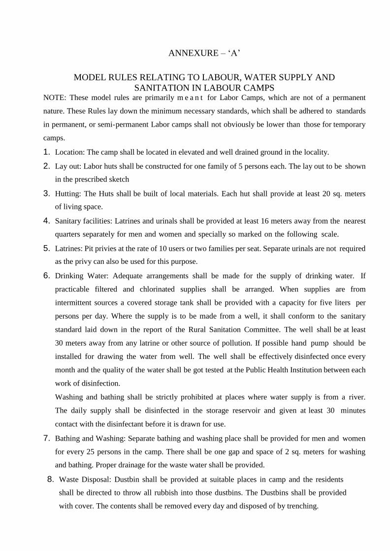
ANNEXURE – ‘A’
MODEL RULES RELATING TO LABOUR, WATER SUPPLY AND
SANITATION IN LABOUR CAMPS NOTE: These model rules are primarily m e a n t for Labor Camps, which are not of a permanent
nature. These Rules lay down the minimum necessary standards, which shall be adhered to standards
in permanent, or semi-permanent Labor camps shall not obviously be lower than those for temporary
camps.
1. Location: The camp shall be located in elevated and well drained ground in the locality.
2. Lay out: Labor huts shall be constructed for one family of 5 persons each. The lay out to be shown
in the prescribed sketch
3. Hutting: The Huts shall be built of local materials. Each hut shall provide at least 20 sq. meters
of living space.
4. Sanitary facilities: Latrines and urinals shall be provided at least 16 meters away from the nearest
quarters separately for men and women and specially so marked on the following scale.
5. Latrines: Pit privies at the rate of 10 users or two families per seat. Separate urinals are not required
as the privy can also be used for this purpose.
6. Drinking Water: Adequate arrangements shall be made for the supply of drinking water. If
practicable filtered and chlorinated supplies shall be arranged. When supplies are from
intermittent sources a covered storage tank shall be provided with a capacity for five liters per
persons per day. Where the supply is to be made from a well, it shall conform to the sanitary
standard laid down in the report of the Rural Sanitation Committee. The well shall be at least
30 meters away from any latrine or other source of pollution. If possible hand pump should be
installed for drawing the water from well. The well shall be effectively disinfected once every
month and the quality of the water shall be got tested at the Public Health Institution between each
work of disinfection.
Washing and bathing shall be strictly prohibited at places where water supply is from a river.
The daily supply shall be disinfected in the storage reservoir and given at least 30 minutes
contact with the disinfectant before it is drawn for use.
7. Bathing and Washing: Separate bathing and washing place shall be provided for men and women
for every 25 persons in the camp. There shall be one gap and space of 2 sq. meters for washing
and bathing. Proper drainage for the waste water shall be provided.
8. Waste Disposal: Dustbin shall be provided at suitable places in camp and the residents
shall be directed to throw all rubbish into those dustbins. The Dustbins shall be provided
with cover. The contents shall be removed every day and disposed of by trenching.
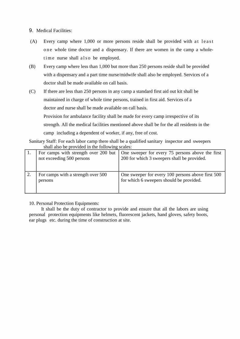
9. Medical Facilities:
(A) Every camp where 1,000 or more persons reside shall be provided with a t l e a s t
o n e whole time doctor and a dispensary. If there are women in the camp a whole-
t i m e nurse shall a l s o be employed.
(B) Every camp where less than 1,000 but more than 250 persons reside shall be provided
with a dispensary and a part time nurse/midwife shall also be employed. Services of a
doctor shall be made available on call basis.
(C) If there are less than 250 persons in any camp a standard first aid out kit shall be
maintained in charge of whole time persons, trained in first aid. Services of a
doctor and nurse shall be made available on call basis.
Provision for ambulance facility shall be made for every camp irrespective of its
strength. All the medical facilities mentioned above shall be for the all residents in the
camp including a dependent of worker, if any, free of cost.
Sanitary Staff: For each labor camp there shall be a qualified sanitary inspector and sweepers
shall also be provided in the following scales:
1. For camps with strength over 200 but
not exceeding 500 persons
One sweeper for every 75 persons above the first
200 for which 3 sweepers shall be provided.
2. For camps with a strength over 500
persons
One sweeper for every 100 persons above first 500
for which 6 sweepers should be provided.
10. Personal Protection Equipments:
It shall be the duty of contractor to provide and ensure that all the labors are using
personal protection equipments like helmets, fluorescent jackets, hand gloves, safety boots,
ear plugs etc. during the time of construction at site.

ANNEXURE –‘B’
Contractor’s Labor Regulations
The contractor shall pay not less than fair wages to laborers engaged by him in the work.
Explanation:
(a) “Fair Wages” means wages payable to the laborers on the date of payment
whether for time or piece work as notified from time to t ime and where such wages
have not been so notified the wages prescribed by the labor Department for the division
in which the work is done.
(b) The contractor shall, notwithstanding the provisions of any contract to the contrary,
cause to be paid a fair wage to laborers indirectly engaged on the work including any
labor engaged by his sub-contractors in connection with the said work as if laborers had
been immediately and directly employed by him.
(c) In respect of all laborers directly or indirectly employed on the works for the
performance of the contractor’s part of this agreement, the contractor shall comply with
or cause to be complied with all the Labor Laws for the time being in force in India.
(d) The Engineer-in-Charge shall have the right to deduct from the money due to
contractor any sum required or making good the loss suffered by a worker or workers
by reason of non-fulfillment of the conditions of the contract for the benefit of the
workers, non-payment of wages or of deduction made from his or their wages which
are not justified by their terms of the contract or non-observance of regulations.
(e) The contractor shall be primarily liable for all payments to be made under and for the
observance of the l aws in c l ud in g regulations without prejudice to his right to
claim indemnity from his sub-contractors.
(f) All the the labor laws including regulations shall be deemed to be a part of this
contract and any breach thereof shall be deemed to be a breach of this contract.
(g) The contractor shall obtain a valid license under the Contract (Regulation and
Abolition) Act, in force and rules made thereunder by the competent authority from
time to time before commencement of work and continue to have a valid license until
the completion of the work.
Any failure to fulfill this requirement shall attract the penal provisions of the laws
and this contract arising out of the resulted non-execution of the work assigned to the
contractor.
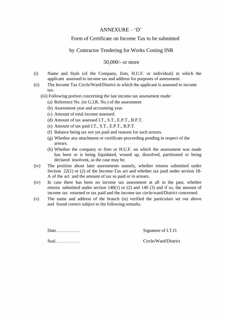
ANNEXURE – ‘D’
Form of Certificate on Income Tax to be submitted
by Contractor Tendering for Works Costing INR
50,000/- or more
(i) Name and Style (of the Company, firm, H.U.F. or individual) in which the
applicant assessed to income tax and address for purposes of assessment.
(ii) The Income Tax Circle/Ward/District in which the applicant is assessed to income
tax.
(iii) Following portion concerning the last income tax assessment made:
(a) Reference No. (or G.I.R. No.) of the assessment
(b) Assessment year and accounting year.
(c) Amount of total income assessed.
(d) Amount of tax assessed I.T., S.T., E.P.T., B.P.T.
(e) Amount of tax paid I.T., S.T., E.P.T., B.P.T.
(f) Balance being tax not yet paid and reasons for such arrears.
(g) Whether any attachment or certificate proceeding pending in respect of the
arrears.
(h) Whether the company or firm or H.U.F. on which the assessment was made
has been or is being liquidated, wound up, dissolved, partitioned or being
declared insolvent, as the case may be.
(iv) The position about later assessments namely, whether returns submitted under
Section 22(1) or (2) of the Income-Tax act and whether tax paid under section 18-
A of the act and the amount of tax so paid or in arrears.
(iv) In case there has been no income tax assessment at all in the past, whether
returns submitted under section 148(1) or (2) and 140 (3) and if so, the amount of
income tax returned or tax paid and the income tax circle/ward/District concerned.
(v) The name and address of the branch (is) verified the particulars set out above
and found correct subject to the following remarks.
Date……………. Signature of I.T.O.
Seal……………. Circle/Ward/District
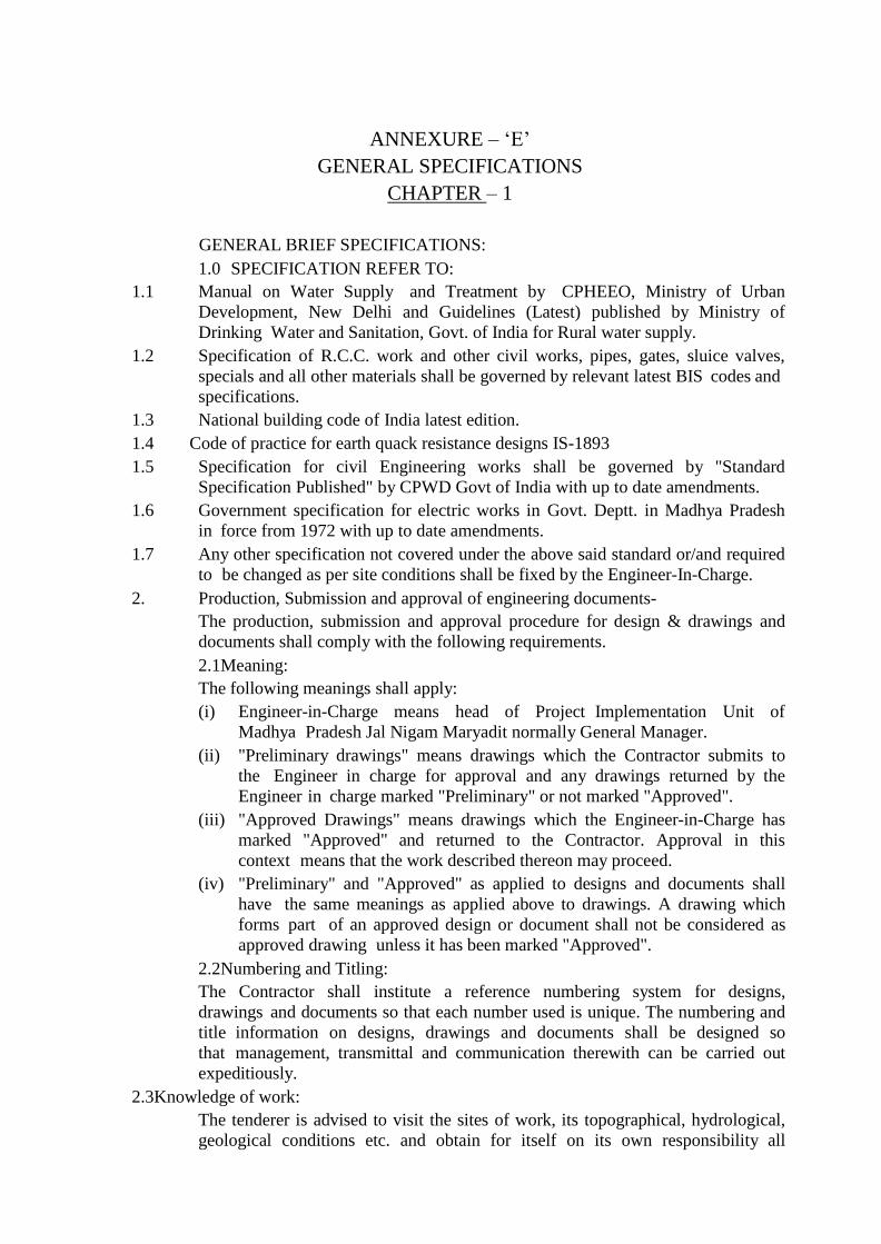
ANNEXURE – ‘E’
GENERAL SPECIFICATIONS
CHAPTER – 1
GENERAL BRIEF SPECIFICATIONS:
1.0 SPECIFICATION REFER TO:
1.1 Manual on Water Supply and Treatment by CPHEEO, Ministry of Urban
Development, New Delhi and Guidelines (Latest) published by Ministry of
Drinking Water and Sanitation, Govt. of India for Rural water supply.
1.2 Specification of R.C.C. work and other civil works, pipes, gates, sluice valves,
specials and all other materials shall be governed by relevant latest BIS codes and
specifications.
1.3 National building code of India latest edition.
1.4 Code of practice for earth quack resistance designs IS-1893
1.5 Specification for civil Engineering works shall be governed by "Standard
Specification Published" by CPWD Govt of India with up to date amendments.
1.6 Government specification for electric works in Govt. Deptt. in Madhya Pradesh
in force from 1972 with up to date amendments.
1.7 Any other specification not covered under the above said standard or/and required
to be changed as per site conditions shall be fixed by the Engineer-In-Charge.
2. Production, Submission and approval of engineering documents-
The production, submission and approval procedure for design & drawings and
documents shall comply with the following requirements.
2.1Meaning:
The following meanings shall apply:
(i) Engineer-in-Charge means head of Project Implementation Unit of
Madhya Pradesh Jal Nigam Maryadit normally General Manager.
(ii) "Preliminary drawings" means drawings which the Contractor submits to
the Engineer in charge for approval and any drawings returned by the
Engineer in charge marked "Preliminary" or not marked "Approved".
(iii) "Approved Drawings" means drawings which the Engineer-in-Charge has
marked "Approved" and returned to the Contractor. Approval in this
context means that the work described thereon may proceed.
(iv) "Preliminary" and "Approved" as applied to designs and documents shall
have the same meanings as applied above to drawings. A drawing which
forms part of an approved design or document shall not be considered as
approved drawing unless it has been marked "Approved".
2.2Numbering and Titling:
The Contractor shall institute a reference numbering system for designs,
drawings and documents so that each number used is unique. The numbering and
title information on designs, drawings and documents shall be designed so
that management, transmittal and communication therewith can be carried out
expeditiously.
2.3Knowledge of work:
The tenderer is advised to visit the sites of work, its topographical, hydrological,
geological conditions etc. and obtain for itself on its own responsibility all
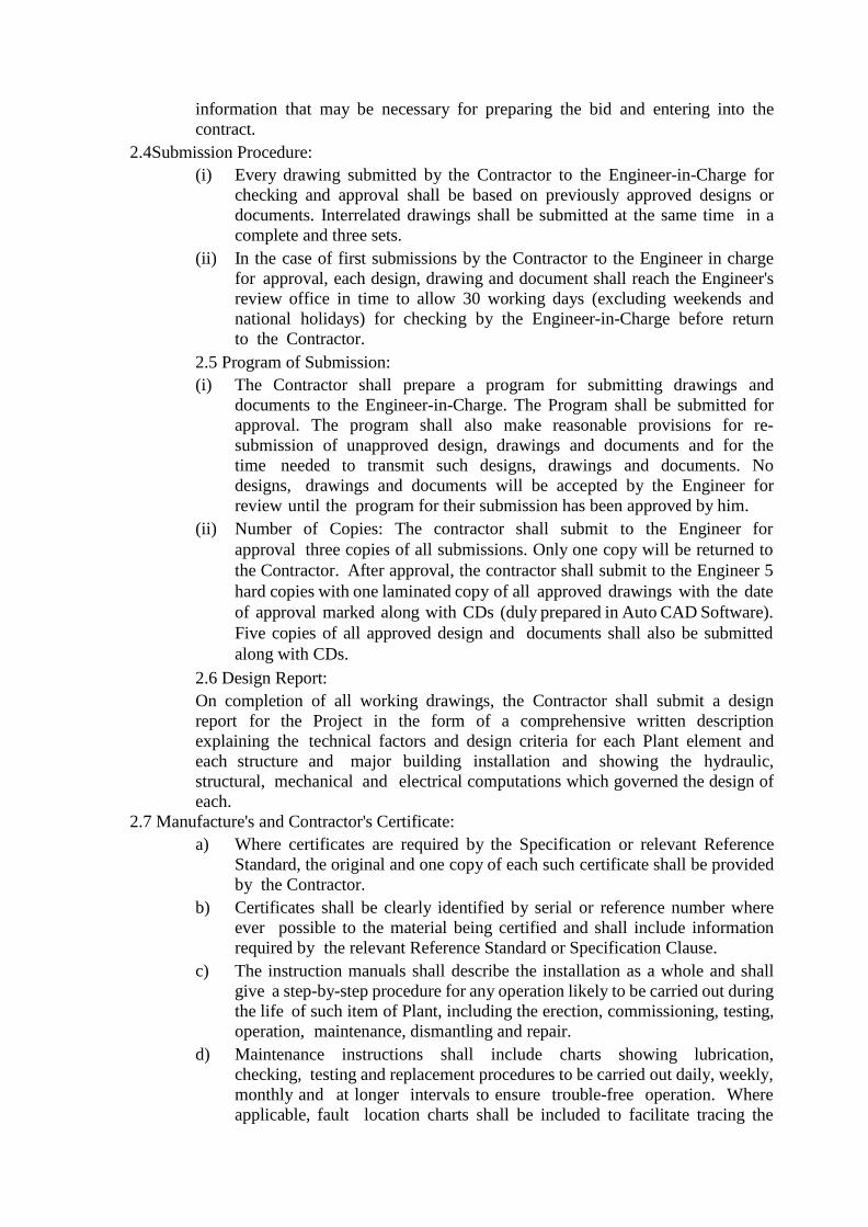
information that may be necessary for preparing the bid and entering into the
contract.
2.4Submission Procedure:
(i) Every drawing submitted by the Contractor to the Engineer-in-Charge for
checking and approval shall be based on previously approved designs or
documents. Interrelated drawings shall be submitted at the same time in a
complete and three sets.
(ii) In the case of first submissions by the Contractor to the Engineer in charge
for approval, each design, drawing and document shall reach the Engineer's
review office in time to allow 30 working days (excluding weekends and
national holidays) for checking by the Engineer-in-Charge before return
to the Contractor.
2.5 Program of Submission:
(i) The Contractor shall prepare a program for submitting drawings and
documents to the Engineer-in-Charge. The Program shall be submitted for
approval. The program shall also make reasonable provisions for re-
submission of unapproved design, drawings and documents and for the
time needed to transmit such designs, drawings and documents. No
designs, drawings and documents will be accepted by the Engineer for
review until the program for their submission has been approved by him.
(ii) Number of Copies: The contractor shall submit to the Engineer for
approval three copies of all submissions. Only one copy will be returned to
the Contractor. After approval, the contractor shall submit to the Engineer 5
hard copies with one laminated copy of all approved drawings with the date
of approval marked along with CDs (duly prepared in Auto CAD Software).
Five copies of all approved design and documents shall also be submitted
along with CDs.
2.6 Design Report:
On completion of all working drawings, the Contractor shall submit a design
report for the Project in the form of a comprehensive written description
explaining the technical factors and design criteria for each Plant element and
each structure and major building installation and showing the hydraulic,
structural, mechanical and electrical computations which governed the design of
each.
2.7 Manufacture's and Contractor's Certificate:
a) Where certificates are required by the Specification or relevant Reference
Standard, the original and one copy of each such certificate shall be provided
by the Contractor.
b) Certificates shall be clearly identified by serial or reference number where
ever possible to the material being certified and shall include information
required by the relevant Reference Standard or Specification Clause.
c) The instruction manuals shall describe the installation as a whole and shall
give a step-by-step procedure for any operation likely to be carried out during
the life of such item of Plant, including the erection, commissioning, testing,
operation, maintenance, dismantling and repair.
d) Maintenance instructions shall include charts showing lubrication,
checking, testing and replacement procedures to be carried out daily, weekly,
monthly and at longer intervals to ensure trouble-free operation. Where
applicable, fault location charts shall be included to facilitate tracing the
cause of malfunction or breakdown.
e) A section dealing with procedures for ordering spares shall also be included
in the instruction.
f) Three draft copies of the manual shall be submitted to the Engineer's
Representative prior to commissioning the works. Five final copies of the
amended and corrected manuals and drawings shall be provided at the
commencement of the period of Maintenance.
g) All the electrical and mechanical equipment’s shall be subjected to approval
by third party inspection at place of manufacture, at contractor's cost.
h) Transit insurance of all equipment's shall be the contractor's responsibility.
i) Contractor shall have to take the certificate from the electrical inspector
for regarding all electrical equipment's before commissioning of plant.
j) Important instructions charts shall be framed and fixed at appropriate and
prominent places.
3.1 Maintenance Instructions:
A maintenance manual shall be provided as supporting documents to the
equipment manufacturer's instructions.
(i) Maintenance Manual
A Checking, testing and replacement procedures to be carried out on all
mechanical and electrical plant items on a daily, weekly and monthly basis or
at longer intervals to ensure trouble free operations.
B. Fault location and remedy charts to facilitate tracing the cause of
malfunctions or breakdown and correcting faults.
C. A complete list of recommended lubricants, oils and their charts.
D. A spares schedule, which shall consist of a complete list of item wised
spares for all electrical and mechanical plant items with ordering references
and part numbers.
E. A complete list of manufacturer's instructions for operation and maintenance
of all bought-out equipment. The list shall be tabulated in alphabetical order
giving the name of the Supplier/Manufacturer, identification of the plant
item giving the model number and the literature provided including
instruction leaflets and drawing numbers.
F. Preventive maintenance details.
4. Record Drawings:
The Contractor shall provide record drawings including those drawings
submitted by the Contractor to show the whole of the plant as installed and all
civil works as built. These shall include all such drawings, diagrams and
schedules as are necessary for a complete understanding of the works.
Information given on record drawings shall include tolerance, clearances,
loadings, finishes, materials and ratings of Plant and associated civil works.
The Contractor shall ensure that the approved and completion drawings are
marked up, to show the condition of plant as installed and associated Civil
Works, as built and two copies of such marked up prints shall be submitted to
the Engineer-in-Charge for approval prior to the preparation of Record
Drawings. Submission to and approval by the Engineer-in-Charge or Record
Drawings shall be pre-requisite for the last taking over certificate. All the
Record Drawings shall be of A2 size, in five copies, out of which 3 sets shall
be plastic laminated for long-life. In addition, one set of Microfilm of all the
Record Drawings shall also be furnished. The text of all the reports shall be
prepared on a widely used IBM compatible MS Word / MS Excel, and all the
Drawings shall be prepared using AutoCAD Software and in pdf form. When
reports, drawings are furnished to Jal Nigam, two copies of the processor
files together with 2 copies of a descriptive memorandum linking these files
to the text, drawings etc., shall also be provided to the Jal Nigam on CDs, Pen
drive, data base preferable on MS office and AutoCAD latest versions and
in .pdf form.
4.1 Program of Work:
a) The works to be carried out under this Contract form an essential part of
the execution of this Water Supply Project, Satisfactory progress of the entire
project as a whole depends upon the timely completion of these works. For
this reason, great importance needs to be attached for proper programming
for the works with adequate provision for guarding against all the delays
normally encountered in execution of various activities.
b) The contractor shall include with his tender a critical path network diagram
which commences from the date of issue of Order of Commencement
and includes inter alia the various activities as per the program of works,
furnished as specified in Schedule.
(i) activity duration in months and event times should be in months
from the first event on the network and event numbers:
(ii) a tabulation of months from the starting date of the network to
enable earliest and latest event dates to be read off; duration in months
to be the last day of the month and the monsoon months of 15th
June to 15th October to be specially indicated in the Table:
(iii) the timing of events shown in the program of work to be adhered
to and shown in the network;
(iv) the erection program shall be shown in detail (with not more than 15
activities) with durations in weeks shown in brackets behind the
duration in months on the network diagram wherever considered
necessary;
(v) the program for setting-up, treating, delivery, storage (if necessary)
and placing of filter media (where appropriate) the placing being a
part of the erection program referred to in (iv) above; and
(vi) program for submission of Instruction Manuals and
Record Drawings;
c) As soon as practicable, and in any case not later than four weeks, after
acceptance of his tender the Contractor shall submit to the Engineer-in-
Charge for his approval a program showing the order of procedure in
which he proposes to carry out the works.
d) Particulars to be shown on the program shall include:
(i) Submission of drawings;
(ii) Placing of work orders;
(iii) Stages of manufacture;
(iv) Tests at place(s) of manufacture;
(v) Deliveries to Site;
(vi) Construction of Civil works ready for erection of Plant;
(vii) Mechanical completion of erection at site;
(viii) Tests at site;
(ix) Finishing and completion of civil and electrical woks.
e) Any approval of or consent to the Contractor's program by the Engineer-in-
Charge shall not relieve the Contractor of his duties and responsibilities
under the Contract.
f) Within four weeks from the date of issue of order of commencement for
the works, the Contractor shall submit to the Engineer-in-Charge for his
approval a detailed program of work together with a description of his
proposed methods of working.
g) The dates and times in the program shall allow for compliance and the
completion date for the whole of the works (except for tests on completion
and except for Maintenance) shall comply with the overall time for
completion entered in the Tender.
h) Contractor shall submit the quarterly financial planning along with the
work program. This financial planning shall be according to physical
planning.
4.2 PROGRESS:
a) The Contractor shall submit to the Engineer-in-Charge during the first week
of each month a "Monthly Progress Report" with weighted activities all
in an approved format so that actual progress at the end of the preceding
month may be compared with the Contractor's program with photographs.
Submission of monthly progress report shall be mandatory, if there is no
progress at site, report shall be submitted with comment as no progress with
the reasons.
b) The progress report shall also include status report on the following
approved individual formats:
i) Drawings;
ii) Supplies of Plant Items;
iii) Construction program;
iv) Construction Progress;
v) Overall Progress Curve;
c) From time to time the Managing Director or Engineer-in-Charge shall call
meetings in their office or at the Engineer's Site Office, as they deem
necessary for the purpose of control of the Contract, a responsible
representative of the Contractor shall attend such meetings.
d) The Contractor shall regularly review his program in the light of the progress
actually achieved and shall submit for approval updated PERT/CPM
network and bar charts at intervals to be agreed with the Engineer-in-Charge.
If progress falls behind that needed to ensure timely completion of the
various parts of the works, the Contractor shall submit proposals for
improving his methods and pace of working to the satisfaction of the
Engineer-in-Charge a n d shall take such measures as are needed to ensure
that the works are completed in time.
6. GENERAL SPECIFICATION:
6.1MATERIAL FOR CONSTRUCTION:
The material used for construction shall be governed by the provision of Part - IV
of National Building Code of India and relevant - IS Code of specification with
up to date amendment.
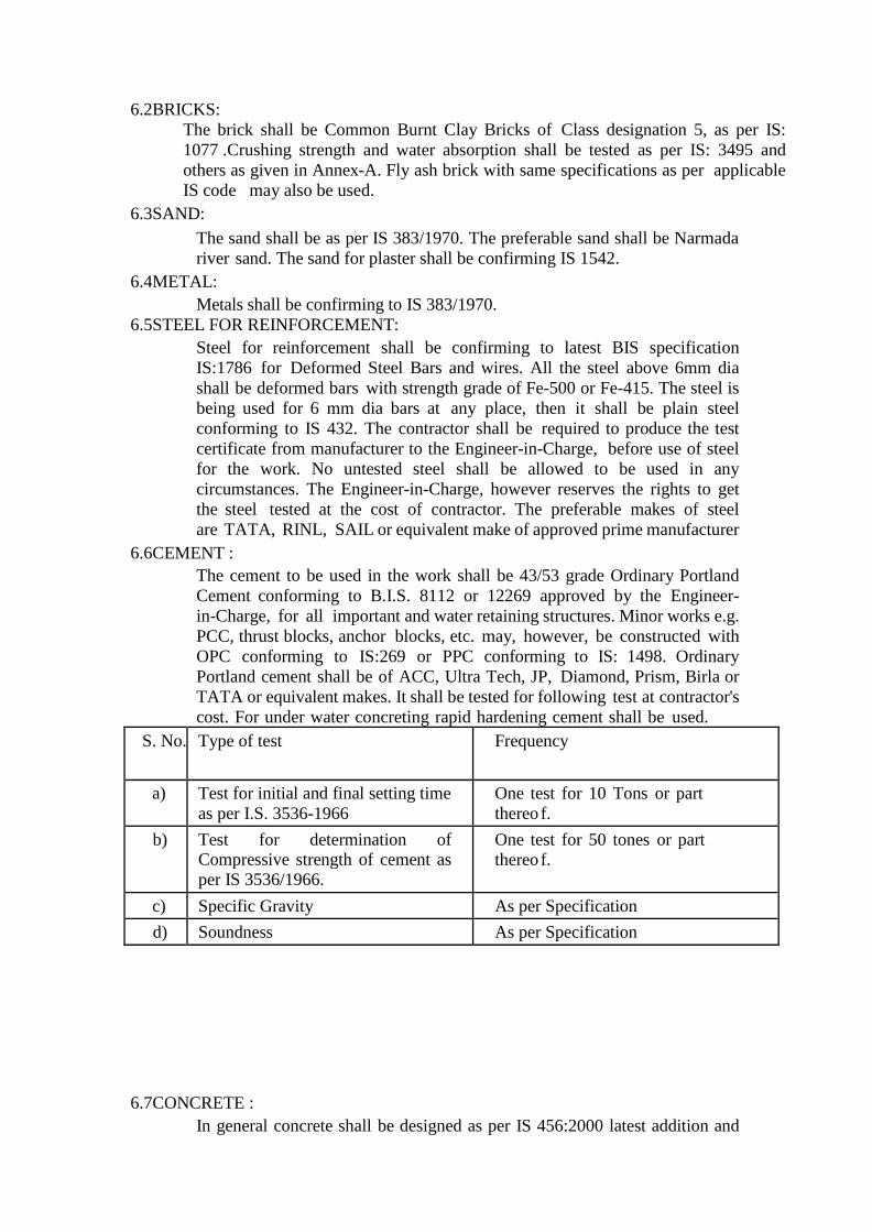
6.2BRICKS:
The brick shall be Common Burnt Clay Bricks of Class designation 5, as per IS:
1077 .Crushing strength and water absorption shall be tested as per IS: 3495 and
others as given in Annex-A. Fly ash brick with same specifications as per applicable
IS code may also be used.
6.3SAND:
The sand shall be as per IS 383/1970. The preferable sand shall be Narmada
river sand. The sand for plaster shall be confirming IS 1542.
6.4METAL:
Metals shall be confirming to IS 383/1970.
6.5STEEL FOR REINFORCEMENT:
Steel for reinforcement shall be confirming to latest BIS specification
IS:1786 for Deformed Steel Bars and wires. All the steel above 6mm dia
shall be deformed bars with strength grade of Fe-500 or Fe-415. The steel is
being used for 6 mm dia bars at any place, then it shall be plain steel
conforming to IS 432. The contractor shall be required to produce the test
certificate from manufacturer to the Engineer-in-Charge, before use of steel
for the work. No untested steel shall be allowed to be used in any
circumstances. The Engineer-in-Charge, however reserves the rights to get
the steel tested at the cost of contractor. The preferable makes of steel
are TATA, RINL, SAIL or equivalent make of approved prime manufacturer
6.6CEMENT :
The cement to be used in the work shall be 43/53 grade Ordinary Portland
Cement conforming to B.I.S. 8112 or 12269 approved by the Engineer-
in-Charge, for all important and water retaining structures. Minor works e.g.
PCC, thrust blocks, anchor blocks, etc. may, however, be constructed with
OPC conforming to IS:269 or PPC conforming to IS: 1498. Ordinary
Portland cement shall be of ACC, Ultra Tech, JP, Diamond, Prism, Birla or
TATA or equivalent makes. It shall be tested for following test at contractor's
cost. For under water concreting rapid hardening cement shall be used.
S. No. Type of test Frequency
a) Test for initial and final setting time
as per I.S. 3536-1966
One test for 10 Tons or part
thereo f.
b) Test for determination of Compressive strength of cement as
per IS 3536/1966.
One test for 50 tones or part
thereo f.
c) Specific Gravity As per Specification
d) Soundness As per Specification
6.7CONCRETE :
In general concrete shall be designed as per IS 456:2000 latest addition and
concrete for water-retaining structures shall be designed as per IS: 3370-Part-
II latest editions. All the components, which are in contact of water and its roof slabs or domes, shall be of minimum Grade M-30 e.g. jack well, intake
well-approach bridge up to H.F.L. inlet chamber, raw water channel, flash mixer, flocculators, filters, module chambers, wash water tank, clear water
sump, reservoirs, pure water channel etc. A ll other components not in
contact with water shall be of minimum M-25 Grade. The cement content per cubic meter of concrete shall not be less than the provisions of IS 456:2000
latest addition.
In general, the clear cover to reinforcement shall be as per IS 456:2000 latest
addition, but additional cover, for corrosive water of 12 mm shall be provided
on all water retaining faces of the structural members as per the provisions of
IS: 3370 (Part II) latest addition.
The concrete shall be prepared as per mix design. All ingredients of concrete shall
be weighed and mixed as per the mix design. All concrete shall be mixed by
concrete mixer and compacted with concrete vibrator only.
The contractor shall set-up a laboratory for testing of metal, concrete, cement on
the site. Slump test shall be carried- out by contractor at his own cost. During
concreting, sample test cube shall be prepared as per the frequency prescribed in
IS 456:2000 and shall be tested by contractor at his own cost. To assess the
strength of cube immediately, accelerated curing testing may also be conducted
as required by the Engineer-in-Charge. If the result of the test shall not be in
confirmity with the required standard and if the Engineer-in-Charge considers that
the structural test is necessary, the same shall be carried-out by the contractor at
his own cost. If the result of this comes again un-satisfactory then the contractor
shall be bound to dismantle and reconstruct the particular portion of work.
The formwork shall be of steel or fresh ply to get the smooth finish.
6.8DESIGNS FOR SEISMIC FORCES:
All the structures shall be designed for seismic loads that may come on the
structure during its lifetime and the design of structure shall be conforming to
IS 1893-2002 'Criteria for earthquake resistance design of structures'.
6.9RAILING:
The railing, wherever provided shall consist of 1.2 M high medium class G.I pipe
posts at 1.5 M c/c embedded welded with reinforcement in cement concrete with
3 rows of 32 mm Medium class G.I pipes railing, duly painted in two or three
coats, so as to give smooth and even finish, with synthetic enamel paint over prime
coat.
6.10PAINTING & FINISHING:
Two coats of Weather Shield Apex painting on the entire exterior civil works shall
be done outside above ground level, interior with oil bound distemper, while 2
coats enamel oil painting shall be done on doors, windows, ventilator and all steel
fabrication work i.e., railing, gantry girder etc. over one coat of primer. The number
of coats may be more than the above specified coats to give smooth and even
surface. All MS items of works in contact with water shall have epoxy coating.
7.0 ELECTRICAL WORKS:
The work shall be carried out as per drawing approved and directed by the Engineer
- in-Charge. Electrification of structures both inside and outside shall be done in
such a manner that standard level of illumination is obtained at all places. Proper
earthing arrangements as per relevant IS specifications shall be provided. The
wiring shall be in concealed only. The total number of light points shall be such
that minimum 300 Lux illumination inside the structures is available, Sufficient
Power points shall be provided.
The intake well below pipe floor, module pipe gallery shall be illuminated with
the help of sodium vapour / LED lamps. On the outside campus also, sodium
vapour / LED lamps shall be provided. On Approach Bridge decorative lighting
shall be provided on each side, suitably spaced in such a way that it provides
prescribed LUX illumination.
7.1 ELECTRIFICATION :-
7.1.1 Earthing :
(i) General
Protective conductors shall be provided for all electrical installations and
associated mechanical Plant and Equipment, exposed steel work and buildings.
Protective conductors shall be provided in accordance with the requirements of IS
3043 and the latest edition of the I E Wiring Regulations/Code of Practice for
Electrical Wiring Installation IS 732.
(ii) Earthing Conductor
Earth electrodes where used shall be galvanized, iron rods in accordance with IS
3043 having outer diameter not less than 38mm. The rod shall penetrate a minimum
of three meters below ground level. Where multi-rods are used a distance of not
less than the driven length shall separate them.
Earth rods shall have hardened tips and caps and be extendable. Galvanized iron
flats buried at a minimum depth of 600mm shall be used for interconnection of rods.
Where soil conditions make the use of rod type electrodes impracticable a grid
configuration may be used comprising horizontally buried bare galvanized iron strip
of dimensions 50mm x 10mm minimum. GI strip shall be buried at a minimum
depth of 600mm.
Each earth electrode rod if used shall be provided with an approved non-ferrous
clamp for the connection of the earthing conductor or tape as required. These
connections shall each be housed in individual concrete inspection chamber set flush
to the finished ground level and shall allow disconnection for testing of individual
electrodes. The chamber shall be permanently marked 'Electrical Earth'.
All materials used for the earth electrode installation shall be purpose made for
the application and site conditions and shall be approved by the Engineer-in-Charge.
Unless otherwise stated i n w r i t i n g i n t h i s a g r e e m e n t , all
excavation of trenches for the installation of the earth electrodes and the
inspection pit shall be carried out by the Contractor.
After the earth installation has been completed the Contractor shall demonstrate to
the Engineer-in-Charge that the resistance of the electrodes to earth and the
continuity of the earth network are within the limits specified. Any additional earth
electrodes and test instruments required for the tests shall be provided by the
Contractor.
Marker posts and plates shall be provided to mark the route of buried tape
electrodes. The markers shall be similar to those provided for cable routes.
(iii) Main Earthing Terminal
A main earth terminal shall be installed in an approved location adjacent to the
incoming supply to a building. This shall be labeled and comprise a 50mm x
6mm minimum cross section copper strip as per IS 3043. The bar shall be of sufficient
length to accommodate bolted earth bonding connections from transformers, major
items of Plant and Equipment and electrical switchgear, building structural steel
work, concrete reinforcement, the earth electrode system and the lightning
protection system. The earthing conductor shall be clearly marked as such and
shall be accessible for disconnection to facilitate testing of the earth electrode
system. For small installations an earthing terminal comprising a single brass stud
of 12mm minimum diameter shall be acceptable.
(iv) Instrument Earth
A separate instrumentation earth shall be established in each control panel. This
shall comprise one or more copper earth bars not less than 25x6mm cross-section
electrically isolated from the steel work of the panel and amounting of power
cables. The instrument earth bar or bars shall be connected radially to the main earth
bar of the control panel.
The instrument earth bar shall be provided for earthing the signal earth connection
of each instrumentation and control device and the screen or screens of each
instrument cable.
The earth bar shall have sufficient brass terminals to terminate all devices etc.
as detailed plus not less than 25% spare terminals.
The screens of instrumentation signal cables shall be earthed at one point only.
This shall normally be the nearest instrument earth bar at the control panel end.
Instrumentation signal screens shall be cut back and insulated at the field
end. The overall earth resistance shall be brought down to less than one
ohm.
7.1.2 Colors :
All cables cores shall be colour coded throughout their length and shall be so
connected between switchboard, distribution board, plant and equipment and
accessories, that the correct sequence or phase colours are preserved throughout the
system.
The colour coding should be as follows :
3 phase : red, yellow and blue
single phase or dc : red and black
earth : green / yellow
control : blue (dc), red
(ac)
7.1.3 Conductors
Copper conductors shall be used for power cables and copper conductors for
control and instrumentation throughout. Cores of cross-sectional area greater than 4
mm². Small power and control cables shall be of a minimum cross section of 2.5
mm². Internal wiring of control panels shall be of a minimum cross-section
1.5mm² flexible and standard.
Instrumentation and control cabling shall be of a minimum cross-section 1.5mm²
for external use and 1.0mm² for internal use.
7.1.4 Cable Fixing
Ties and strapping shall be suitable for securing cable and cable groups to cable tray
or ladder. They shall be resistance to chemicals. Plastic coated metal ties used in
order to obtain corrosion resistance shall not be acceptable. Nylon ties shall be
resistant to the effects of ultra-violet light and shall be self-extinguishing.
Large single cables shall be secured with cable clamps or cable cleats.
7.1.5 Cable Identification:
At each end of each cable, in a uniform and visible position a label shall be fixed on
the cable in accordance with the cable schedule. Labels shall be made of PVC and
shall be indelibly marked to the approval of the Engineer-in-Charge. The label shall
be retained using proprietary nylon strips passing through two fixing holes at
either end of the label. If the cable gland is not normally visible, then the label
shall be fixed inside the panel by means of screws.
7.1.6 Marketing Location of Underground Cables:
The location of all underground cables shall be engraved on brass or other non-
corrodible plates to be fixed to the exterior surface of all walls of buildings 300mm
above ground level and directly above the point where cables pass through the wall.
In addition concrete marker posts shall be installed at intervals of not more than 50m
at all junctions and changes of direction along the cable route. Such marker posts
shall be not less than 200mm high and of substantial construction. A drawing or
sample of a typical marker post shall be submitted for the approval.
The markers shall be marked 'electric cable' both in English and Hindi.
7.1.7 Lamp Test
Facilities shall be provided to test all lamps on an assembly. This shall comprise
a common lamp test section. Operation of the lamp test circuit shall energies a
relay in each section of the assembly in order to light each lamp and enunciator.
The lamp test circuit shall pass through auxiliary contracts on section isolators if
fitted. A short time delay shall ensure that the lamp test supply is retained to allow
visual checking of all lamps.
On small assemblies, less than ten starters, individual lamp test buttons on each
section shall be acceptable unless otherwise specified.
7.1.8 Telemetry Outstation:
This section shall house the telemetry outstation and associated cable marshalling
equipment.
The interior of the telemetry outstation section shall be accessible without
isolation of any drive or circuit. Therefore all voltages in excess of 24V shall be
screened to prevent access.
Each circuit shall be protected by an MCB such that maintenance work can be
carried out with the minimum of interference to running plant.
Interconnection of inputs and outputs to the telemetry outstation shall be
made via single edge knife type terminals to allow easy disconnection.
Analogue signals for connection to any telemetry outstation shall be connected
via a signal isolator which shall allow disconnection of the outstation signal
without disturbance to the operation of the works.
7.1.9 Emergency stop Circuitry:
Each drive or group of drives shall be provided with an emergency stop facility
which shall comprise a red coloured, mushroom headed, stay-put-twist to release
push button. The work shall be carried out strictly in accordance with latest
Indian electrification rule, latest specification of M.P.E.B. and relevant I.S.
specification. Electrification of chemical room, module chamber room, chlorine
room, chlorine storage room, clear water pump house, office room. store room,
L.T. switchgear room, toilet blocks, laboratory block etc. shall be done by
contractor in such a manner that standard level of illumination is obtained. The
wiring shall be concealed only. Separate pipes shall be provided for ordinary,
power wiring and circuit wiring. Circuits shall be decided as per rules. Power
wiring shall only be done in rigid steel conduit pipes. All accessories and pipes
shall be I.S.I. Mark. In wiring copper conductor shall be used. The electrification
shall be done by experienced electrical worker, having valid license. The
contractor shall provide MCC for the load of complete Treatment Plant except
the clear water pumps load.
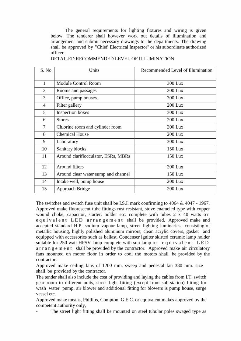
The general requirements for lighting fixtures and wiring is given
below. The tenderer shall however work out details of illumination and
arrangement and submit necessary drawings to the departments. The drawing
shall be approved by "Chief Electrical Inspector" or his subordinate authorized
officer.
DETAILED RECOMMENDED LEVEL OF ILLUMINATION
S. No. Units Recommended Level of Illumination
1 Module Control Room 300 Lux
2 Rooms and passages 200 Lux
3 Office, pump houses. 300 Lux
4 Filter gallery 200 Lux
5 Inspection boxes 300 Lux
6 Stores 200 Lux
7 Chlorine room and cylinder room 200 Lux
8 Chemical House 200 Lux
9 Laboratory 300 Lux
10 Sanitary blocks 150 Lux
11 Around clariflocculator, ESRs, MBRs 150 Lux
12 Around filters 200 Lux
13 Around clear water sump and channel 150 Lux
14 Intake well, pump house 200 Lux
15 Approach Bridge 200 Lux
The switches and switch fuse unit shall be I.S.I. mark confirming to 4064 & 4047 - 1967.
Approved make fluorescent tube fittings rust resistant, stove enameled type with copper
wound choke, capacitor, starter, holder etc. complete with tubes 2 x 40 watts o r
e q u i v a l e n t L E D a r r a n g e m e n t shall be provided. Approved make and
accepted standard H.P. sodium vapour lamp, street lighting luminaries, consisting of
metallic housing, highly polished aluminum mirrors, clean acrylic covers, gasket and
equipped with accessories such as ballast. Condenser igniter skirted ceramic lamp holder
suitable for 250 watt HPSV lamp complete with sun lamp o r e q u i v a l e n t L E D
a r r a n g e m e n t shall be provided by the contractor. Approved make air circulatory
fans mounted on motor floor in order to cool the motors shall be provided by the
contractor.
Approved make ceiling fans of 1200 mm. sweep and pedestal fan 380 mm. size
shall be provided by the contractor.
The tender shall also include the cost of providing and laying the cables from I.T. switch
gear room to different units, street light fitting (except from sub-station) fitting for
wash water pump, air blower and additional fitting for blowers is pump house, surge
vessel etc.
Approved make means, Phillips, Compton, G.E.C. or equivalent makes approved by the
competent authority only,
- The street light fitting shall be mounted on steel tubular poles swaged type as
per I.S. 2713 complete including fixing on ground with concrete block with
base plate etc. of
7.00 M. height from ground level.
- All equipment's and material shall be suitably designed and guaranteed for
normal life and satisfactory operation under the climatic conditions prevalent
at site. They should perform as per the characteristics without showing any
sign of overload, overheating etc.
- Detailed specification shall be given for all the mechanical and electrical
equipment's duly guaranteed for their satisfactory performance for at least 12
months from the date of commissioning of plant.
- Before putting the plant in operation all electrical installations, wiring etc.
shall be certified by the contractor and clearance from Govt. Electrical Inspector
shall be taken.
7.2 MOTOR CONTROL CENTER/DISTRIBUTION BOARDS :-
There shall be fixed execution design in sheet metal housing and shall be
suitable for power and light requirement and equipment's under the contract.
A distribution board with M.C.B. shall be located in chemical house to
provide power to alum and lime mixing agitator. Power supply to this
distribution board shall be from main M.C.C. in pump house. This M.C.C. in
form of L.T.O.C.B./A.C.B. shall be provided and fixed by the contractor in pump
house. The cooling etc. shall also be done by contractor.
The weather proof distribution board to energize flash mixer, clariflocculator
shall be located at suitable point.
For external and internal illumination in the module chamber room, a separated
D.B. shall be mounted in this room. This D.B. shall consist of control for wash
water pump air compressor and lighting etc.
For external and internal lighting of chlorine room and storage room a separate D.B.
shall be mounted. This will connect with L.T.O.C.B./A.C.B. A separate D.B. shall
be mounted to control the external and internal lighting of pump house.
A.D.B. for control of street light shall also be mounted in the pump house.
7.3 STARTER / PUSH BUTTON :-
For motors up to 5 H.P. D.O.L. push button starters shall be used. Motors above 5
H.P. shall have air break manually / electrically operated star delta starters.
7.4 CABLES: -
All power and control cables should be of standard make and I.S.I. mark
7.5 EARTHING FOR MOTORS :-
As per I.E. rule, 440 V motors shall be earthed to two independent earth station
common to all motor/M.C.C. etc. using shortest routes, and by interconnecting earth
wires / strips lightening Arrestor shall be provided at two distant location of buildings.
The earthling shall be done after digging the pit of standard size and depth with
600 mm x 600mm x 3 mm thick copper earth plate including accessories and providing
masonry enclosure in C.M. cover plate having locking arrangement and G.I. watering
pipe
20mm. size 2.7 m. long etc. with charcoal or coke and salt filling etc. complete.
7.6 LIGHTENING CONDUCTOR :-
Lightening conductor of 25mm dia 300mm long copper tube having single prong at
top with 85mm. dia thick copper base plate including holes shall be provided. It shall
have
20x 3mm thick copper strip with necessary support to connect the strip to surface
up to earthing plate. It shall be provided at the top of wash water tank.
7.7 ELECTRIC CONNECTION CHARGES
Power supply (excluding electric connection charges/security deposit) at all points i.e.
Intake, WTP, BPT, all over head tank all staff quarters, office building store etc. shall
be in the scope of contractor.
7.8 LENGTH OF ELECTRIC POWER LINE
Length of the electric power line 33 kV/11 kV shall be as per the scope of work,
any change in the length will be considered as variation.
8.0 VALVES & SPECIALS:-
Specification for Valves and specials and other materials shall be governed by relevant
latest BIS specifications with their amendments, the material of these valves and
specials should be DI with IS Mark, where DI pipeline and HDPE pipelines have been
laid. The valves, which are not available conforming to BIS specification its face to face
dimensions and flanges, shall be confirming to IS 14846-2000. The make of valves and
specials have been given in Chapter 1.9B. All Valves shall comply to IS/BS standard
and inspection and testing certificate shall be produced to Engineer in Charge.
All the pipes shall be fitted with sluice valve as per BIS/BS standards and wherever
necessary provided with inspection chambers.
9.0 Units of Water Treatment Plant:- All units and components of Water Treatment Plant
shall be designed as per recommendations of Manual on Water Supply and
Treatment, published by CPHEEO, Ministry of Urban Development, Govt. of India.
10.0 Minimum size of D.I. pipelines:- The minimum size of D.I. K-7 or K-9 pipes shall
be of 100 mm.
11.0 MS pipe of 600 mm and above dia.:- Wherever the size of pipeline is designed as 600
mm dia. or above, it shall be provided with Mild Steel pipes also as per specifications
of relevant latest B.I.S. Code of Practice, suitably lined and out coated with cement
mortar or epoxy coating (not merely painting) to prevent it from corrosion.
12.0 Boundary wall:- All the sites of structures e.g. intake well, pump houses, ESRs,
MBRs and/or B.P. Tanks, WTP etc. shall be provided with boundary wall of
minimum 2.0 m height from GL. The Boundary wall shall be of min. 20 cm thick
brick masonry suitably constructed on RCC beams connected with RCC columns
and having MS fabricated gate of minimum 3.5 m width.
13 Approach roads:- Wherever the specifications for approach roads are not given
in NIT, it shall be WBM and overlaying Bituminous layers as per MOST
specifications applicable for such roads. The width of roads shall be minimum
3.0 m. The specifications of BT road consist of Granular sub base with coarse
graded material (Table 400-2), compacted WBM layers with Grading-II (a) and
Grading- III (a). Primer coat with bitumen emulsion @ 0.60 kg/sqm, tack coat
@ 0.30 kg/sqm, Open Graded Premix surfacing (Case-II) and seal coat using
Type-A and B seal coats.
Managing Director
Madhya Pradesh Jal Nigam Maryadit
Vindhyachal Bhawan, Bhopal
CHAPTER – 1.1
BRIEF SPECIFICATIONS OF INTAKE WELL-CUM- PUMP-
HOUSE
Scope of work:
The tenderer shall be required to complete the following works including the
planning, design, construction, testing, commissioning and O&M -
i) Intake Well – Cum Pump House in the submergence of Bansagar Dam near
village Sukwari (near Markendeya Ghat) to draw raw water from top most layers
in different seasons and also from the lowest level of water as below-
a) Floor area should be sufficient to have panels, switch gears and
capacitors etc. The floor area shall be increased to the functional
requirement for all these, if necessary.
b) The size of the intake well should be such that it has adequate capacity
to draw 2 0 6 . 6 2 Million liter raw water in 23 hours having minimum
14.00 meter internal diameter.
c) The size of the pump house should have adequate capacity for installation
& maintenance of the pumps/motors with minimum 14.00 meter internal
diameter, to house the pumping equipment's, as per specifications
capable to supply 206.62 Million liters water in 23 hours. The pump house
may have separate floor for pumps and motors.
d) Intake well should have a proper grit chamber for the retention of
half minute or as required from the design consideration and should
have a mechanical scraping belt or bucket for de-gritting the well.
e) Suitable sluice valves/gates at the entrance of Intake well have to be
provided to control the flow with manual as well electrical operated
arrangement.
f) Proper arrangement for fresh air circulation should be there so that
suffocation does not occur during the maintenance of the well.
g) A RCC staircase to Intake well with proper railing up-to bottom, with
landing at intermittent points has to be provided.
h) A separate gantry of suitable capacity is to be provided for
maintenance purposes.
i) Proper ventilation/lighting arrangement as per the BIS requirements for
the pumps and motors are to be provided.
j) Proper lightening arrester arrangement as per BIS standards are to be
made for Intake well.
k) The internal diameter of the Intake well and pump house shall be
minimum 14.00 m.
l) The intake well shall have inlet port arrangements at different levels,
screens, racks, sluice valve arrangement with both manual and electrically
operated arrangement.
ii) Approach bridge
A suitable approach bridge, having clear width of minimum 5 m with suitable return
arrangement is to provide to connect the Intake well with the nearest ground. The
bridge should be sufficient to carry IRC class B loading.
iii) The scope of work includes all the necessary works required including ancillary
works if any, to be executed to make available the desired quantity of water into
the Intake and/or Jack well. No extra payment will be made on this account to the
contractor and rates for such work shall be deemed to be included in the quoted
rates.
The Specifications for construction of Intake well cum pump house and electrical
mechanical equipment's for the Water supply scheme are given in the following paras:
1 General
1.1 The job implies all works from detailed preliminary investigations to the final
commissioning of the structure including all ancillary works such as construction of
coffer dam for diversion of flow of river, dewatering, bailing out of water etc.
including testing during trial run period and defects liability and O&M period of this
contract.
1.2 The tenderer’s offer should be technically sound and economically viable.
1.3 The tenderer is required to arrange complete construction of civil works, supply and
installations of all the pumping sets until the whole structure is handed over to the Jal
Nigam staff authorized by the M.D/ Engineer-in-Charge. Testing will also have to be
carried out at contractor’s cost and it will be the responsibility of the contractor to
ensure that respective standards are achieved.
1.4 The Intake well is required to house vertical turbine pumps and other accessories,
therefore coordination with the pump suppliers and hydraulic model studies will be
essential for deciding arrangements of pump installations, the contractor will have to
carry out any modification, addition and alteration to the design and structure to meet
such requirement if needed without causing any extra liabilities on the MP Jal Nigam.
He will design the Intake well cum pump house in such a manner that it also meets the
efficient vortex free hydraulic and structural requirements of pumps/motors to be
installed to meet such requirements.
The trash rack of the Intake well should be suitable for ultimate capacity of this project
to draw 206.62 Million liters in 23 hours through different ports at same level. In the
Intake well cum pump house total 5 numbers of vertical turbine pumps (3 Working +
2 Standby) which may be replaced in future after O&M period, for ultimate capacity.
These pumps will operate individually or in all possible combinations. The Civil
structure will have to be such that no vortex is formed and there is no interference
or pump starvation by operating these pumps in any combination or independently.
However for structural design suitable static loading for each motor pump assembly
may be considered at the points where they will be fixed. In addition to this a live
load at motor and discharge pipe floor may also be considered. The essential vibration
effect factors will also be considered.
2 Detailed investigation
It will be necessary for the tenderer to depute technical personnel to visit the site
of construction to get them acquainted with the prevailing site conditions and
for any additional information contact the office of Engineer-in –charge to collect
all relevant information for planning and designing the entire construction work of
said structure. A safe RL of HFL should be find out by the contractor for planning
water supply head works at the Intake well site.
Main levels of Bansagar dam -
1. MWL 342.934 m
2 FRL 341.649 m
3 MDDL 323.100 m
The tenderer shall confirm the above topographical and hydrological
investigations done/data given and satisfy themselves before submission of their
tender as these details are just for guidance. No claims on variation of above data
shall be admissible & considered for payment.
2.1 Preparation of technical report-
The tenderer shall prepare a technical report for design and construction of the
said work incorporating complete information, specifications and data for
submission along with his tender.
2.2 Detail Designs and Drawings-
2.2.1 On acceptance to tender the contractor will have to submit structural details,
designs and drawings of the entire structure including allied works within 30 days
from the date of acceptance of his offer. Besides this a general layout drawing
showing the arrangement of installations of vertical turbine pumping sets, piping
arrangement at discharge floor, location of their starters control panels, main switch
board, cable laying etc. should also be supplied by the contractor. Entire civil works
related to these items viz. foundations for pump, motor, cable trenches ducts and
opening in staining wall of Intake, opening in slabs for pump opening pumps,
gantry cables and pipes etc. in all respects are to be provided by the contractor and
shall be a part of this contract.
2.2.2 The responsibility for design, construction, structural stability and water tightness
shall rest solely with the contractor. The contractor shall have to submit four sets
of completion drawings immediately after completion of work.
2.2.3 Detailed design shall include all the required calculations for all the components
including the following:-
(i) Foundation depth and its design for trash rack structure, Intake well cum
pump house Staining thickness and its design for various hydraulic conditions.
(ii) Pipe floor and motor floor design for anticipated loading conditions.
(iii) Gantry support to be designed for ultimate loading capacity including weight
of gantry girder crane.
(iv) Design of shoring scaffolding.
(v) Protection work against flood and erosion of banks near Intake well.
(vi) Design of inlet ports and/or approach conduit.
(vii) Design of Approach road/ramp with suitable approach
2.2.4 However, at the time of submitting tender, the contractor shall have to submit
an outline plan and section of the proposed work showing different components and
scope of the work.
3.0 Foundation of Intake well-
3.1 The foundation of Intake well should be designed and constructed
considering the strata met in foundation, maximum scour depth, weight of
superstructure, water force, wind force, live load of pumps, motors and
pipes, dynamic forces due to vibrations of pumps, water thrust, seismic
force, and other live loads, water thrust, uplift pressure etc. Any other forces
required to be taken for safe design, which are not mentioned here, should
also be taken into consideration for the design.
3.2 The drawings showing location of proposed work are enclosed for guidance
only. The work of foundation also includes the work of dewatering of water,
shoring of sides of excavation, scaffoldings, de-silting of foundation,
construction of coffer dam etc. for which no extra payment shall be made to
contractor. The tenderers are therefore advised to inspect the site of
construction before tendering their offer to ascertain the quantum of such works.
The tenderer shall be deemed to have full knowledge of all the relevant
documents, proposed site of construction, soil samples or strata at site. The
concrete mix for foundation RCC work should not be weaker than M30 and
the stresses in concrete shall be taken as per IS 3370 and other relevant BIS
codes/specifications.
3.3 Blasting in foundation shall be permitted only by the competent authority if the
contractor guarantees that such operation shall not pose any threat of damages.
3.4 The foundation of Intake well shall be taken down to such depth that it is safe
against scouring, settlement, overturning, floating logs and sliding. The depth of
foundation below the scour line shall not be less than 1.5 metres for adequate
anchorage purpose. In case of foundation resting on rock, the minimum
embedment in the rock shall be 1.5 metres. However minimum depth below the
scour line has to be ensured considering the sufficient factor of safety as per
prevailing IS and IRC norms. The minimum bottom floor level of intake well
should be such, so that the water can be drawn up-to the lowest supply level.
The laying of foundation concrete under water shall be done by skip boxes or
termites pipes with prior permission of the engineer in charge. Pumping out of
water shall not be permitted from the time of placing concrete up-to 24 hours
thereafter.
3.5 Sufficient dowel/ Anchor bars should be provided in the foundation by drilling
suitable diameter holes in the foundation rock and fixing for steel bars and
grouting it with suitable epoxy compounds.
3.6 Construction of trash rack structure, Intake well cum pump house
The R.C.C trash rack structure shall have the minimum suitable floor area, and
for summer and fair weather & monsoon season three inlet ports should be
provided at suitable levels.
Control sluices for lower most and monsoon level ports shall be above HFL at
Intake floor level where as all upper sluices shall be provided in the staining of
the trash rack and inlet lower and operating gears from the approach floor at top
manually and electrically. The opening in the trash rack structure has to be
provided in such a way that it is not obstructed due to any floating logs/ big
boulders or other floating bodies. And it should be able to draw designed flow
from the river at each of the ports. The top level of trash rack structure has to
connect to Intake well with an approach. Rose pieces shall be designed for 50%
clogging.
3.7 The R.C.C Intake well with RCC framed structure pump house structure
shall be having a minimum dia of 14.00 m internal with a minimum discharge
floor area for 5 numbers of vertical turbine pumping sets with all its appliances
and appurtenances. These shall be placed such as to have a clear space of 1.5
m in between the pumps/ motors, and the minimum distance of the pump/motor
from the wall should not be less than 1.5 m, and should be designed to carry
the static load, dynamic and impact load each excluding dead load of floor.
The motor floor should have a minimum floor area to accommodate starters
and capacitors for motor floor level; motor floor slab has to be designed
accordingly. The arrangement of beams for slab should be given in such a way
that these do not obstruct motor foundation and column assembly of pumps,
valves, pipelines. The head room on discharge floor shall not be less than 3.0
M below the bottom of the beams of motor floor. Sufficient sand filling in sunk
wells are to be made as per IRC clause 1207.
3.8 Staircase:
A R.C.C. staircase of minimum 1.0m width with railing for a s u i t a b l e
live load of discharge floor level to bottom of the Intake well should be
provided, on the inner circumference of the steining. The stairs shall be
provided in such a way that there is no obstruction to inlet ports or operation
rods etc. The intermediate landings should be provided at about 4.0 M vertical
intervals. The stairs should be provided with railing as per specifications.
3.9 Inlet ports:
The well staining shall be provided with 3 Nos. inlet ports with suitable thimble
plates, gates, operating rods manual/electrical operated and strainers at various
levels and directions to draw water from maximum draw down level to highest
water level. Each inlet port shall be designed to allow a flow of raw water at the
design rate of flow. The location and R.L of these ports may be altered if
required during construction if desired by the Engineer-in-charge. These inlet
ports/pipes shall be provided with sluices gates/valves with spindles, wheels and
works gears so as to operate them from pipe floor level. The size of suction well
and grit chamber shall be sufficient so that no vortex eddies or cavitation's
effects are experienced on pumps.
4.0 Pipe floor or Discharge floor:
Pipe floor should be provided to house all discharge pipes, valves and manifold
for all the vertical turbine pumping sets as per requirement. The floor slab
should be designed for a uniformly distributed expected live load and moving
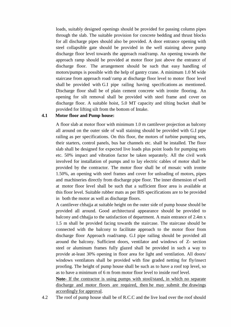
loads, suitably designed openings should be provided for passing column pipes
through the slab. The suitable provision for concrete bedding and thrust blocks
for all discharge pipes should also be provided. A door entrance opening with
steel collapsible gate should be provided in the well staining above pump
discharge floor level towards the approach road/ramp. An opening towards the
approach ramp should be provided at motor floor just above the entrance of
discharge floor. The arrangement should be such that easy handling of
motors/pumps is possible with the help of gantry crane. A minimum 1.0 M wide
staircase from approach road/ ramp at discharge floor level to motor floor level
shall be provided with G.I pipe railing having specifications as mentioned.
Discharge floor shall be of plain cement concrete with ironite flooring. An
opening for silt removal shall be provided with steel frame and cover on
discharge floor. A suitable hoist, 5.0 MT capacity and tilting bucket shall be
provided for lifting silt from the bottom of Intake.
4.1 Motor floor and Pump house:
A floor slab at motor floor with minimum 1.0 m cantilever projection as balcony
all around on the outer side of wall staining should be provided with G.I pipe
railing as per specifications. On this floor, the motors of turbine pumping sets,
their starters, control panels, bus bar channels etc. shall be installed. The floor
slab shall be designed for expected live loads plus point loads for pumping sets
etc. 50% impact and vibration factor be taken separately. All the civil work
involved for installation of pumps and to lay electric cables of motor shall be
provided by the contractor. The motor floor shall be of mosaic with ironite
1.50%, an opening with steel frames and cover for unloading of motors, pipes
and machineries directly from discharge pipe floor. The inner dimension of well
at motor floor level shall be such that a sufficient floor area is available at
this floor level. Suitable rubber mats as per BIS specifications are to be provided
in both the motor as well as discharge floors.
A cantilever chhajja at suitable height on the outer side of pump house should be
provided all around. Good architectural appearance should be provided to
balcony and chhajja to the satisfaction of department. A main entrance of 2.4m x
1.5 m shall be provided facing towards the staircase. The staircase should be
connected with the balcony to facilitate approach to the motor floor from
discharge floor Approach road/ramp. G.I pipe railing should be provided all
around the balcony. Sufficient doors, ventilator and windows of Z- section
steel or aluminum frames fully glazed shall be provided in such a way to
provide at-least 30% opening in floor area for light and ventilation. All doors/
windows ventilators shall be provided with fine graded netting for fly/insect
proofing. The height of pump house shall be such as to have a roof top level, so
as to have a minimum of 6 m from motor floor level to inside roof level.
Note- If the contractor is using pumps with stool/stand, in which no separate
discharge and motor floors are required, then he may submit the drawings
accordingly for approval.
4.2 The roof of pump house shall be of R.C.C and the live load over the roof should
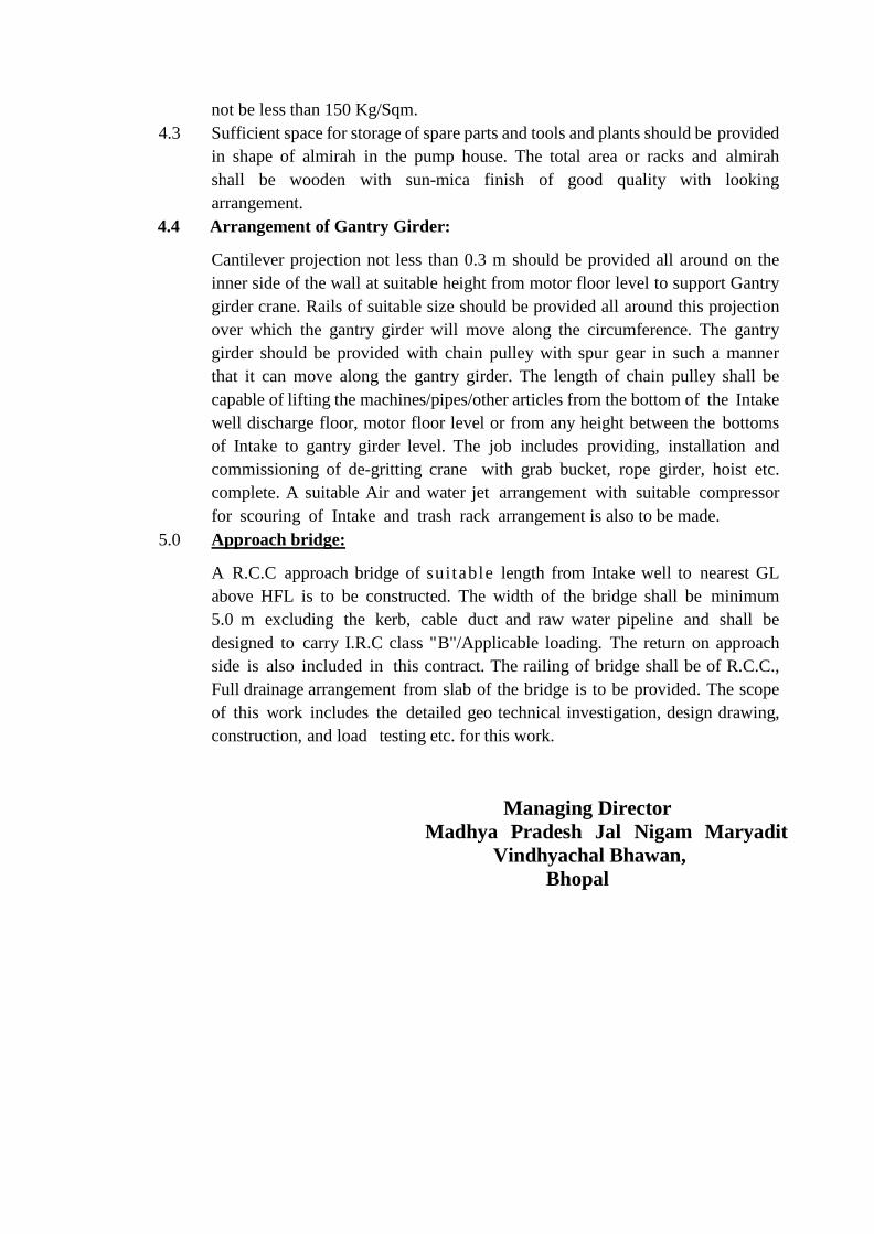
not be less than 150 Kg/Sqm.
4.3 Sufficient space for storage of spare parts and tools and plants should be provided
in shape of almirah in the pump house. The total area or racks and almirah
shall be wooden with sun-mica finish of good quality with looking
arrangement.
4.4 Arrangement of Gantry Girder:
Cantilever projection not less than 0.3 m should be provided all around on the
inner side of the wall at suitable height from motor floor level to support Gantry
girder crane. Rails of suitable size should be provided all around this projection
over which the gantry girder will move along the circumference. The gantry
girder should be provided with chain pulley with spur gear in such a manner
that it can move along the gantry girder. The length of chain pulley shall be
capable of lifting the machines/pipes/other articles from the bottom of the Intake
well discharge floor, motor floor level or from any height between the bottoms
of Intake to gantry girder level. The job includes providing, installation and
commissioning of de-gritting crane with grab bucket, rope girder, hoist etc.
complete. A suitable Air and water jet arrangement with suitable compressor
for scouring of Intake and trash rack arrangement is also to be made.
5.0 Approach bridge:
A R.C.C approach bridge of suitable length from Intake well to nearest GL
above HFL is to be constructed. The width of the bridge shall be minimum
5.0 m excluding the kerb, cable duct and raw water pipeline and shall be
designed to carry I.R.C class "B"/Applicable loading. The return on approach
side is also included in this contract. The railing of bridge shall be of R.C.C.,
Full drainage arrangement from slab of the bridge is to be provided. The scope
of this work includes the detailed geo technical investigation, design drawing,
construction, and load testing etc. for this work.
Managing Director
Madhya Pradesh Jal Nigam Maryadit
Vindhyachal Bhawan,
Bhopal
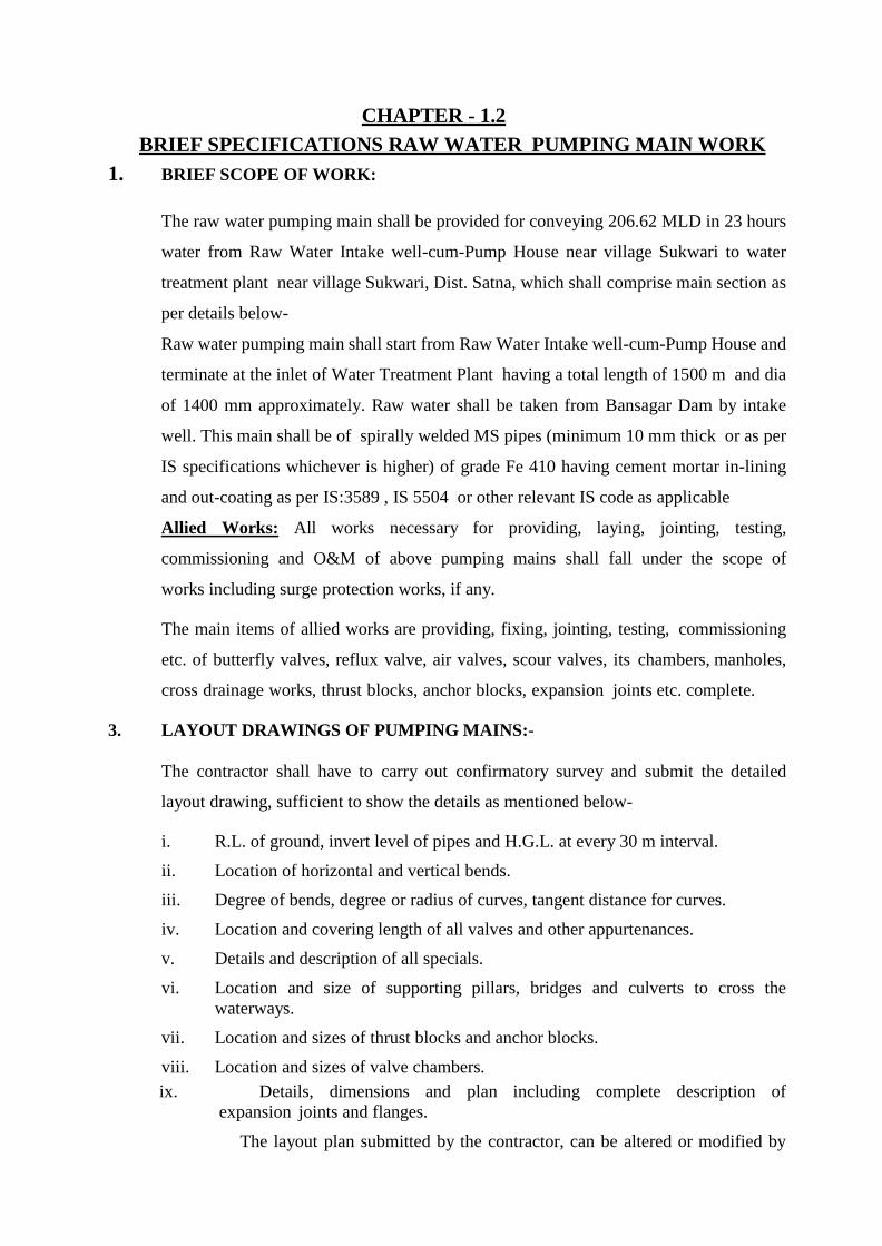
CHAPTER - 1.2
BRIEF SPECIFICATIONS RAW WATER PUMPING MAIN WORK
1. BRIEF SCOPE OF WORK:
The raw water pumping main shall be provided for conveying 206.62 MLD in 23 hours
water from Raw Water Intake well-cum-Pump House near village Sukwari to water
treatment plant near village Sukwari, Dist. Satna, which shall comprise main section as
per details below-
Raw water pumping main shall start from Raw Water Intake well-cum-Pump House and
terminate at the inlet of Water Treatment Plant having a total length of 1500 m and dia
of 1400 mm approximately. Raw water shall be taken from Bansagar Dam by intake
well. This main shall be of spirally welded MS pipes (minimum 10 mm thick or as per
IS specifications whichever is higher) of grade Fe 410 having cement mortar in-lining
and out-coating as per IS:3589 , IS 5504 or other relevant IS code as applicable
Allied Works: All works necessary for providing, laying, jointing, testing,
commissioning and O&M of above pumping mains shall fall under the scope of
works including surge protection works, if any.
The main items of allied works are providing, fixing, jointing, testing, commissioning
etc. of butterfly valves, reflux valve, air valves, scour valves, its chambers, manholes,
cross drainage works, thrust blocks, anchor blocks, expansion joints etc. complete.
3. LAYOUT DRAWINGS OF PUMPING MAINS:-
The contractor shall have to carry out confirmatory survey and submit the detailed
layout drawing, sufficient to show the details as mentioned below-
i. R.L. of ground, invert level of pipes and H.G.L. at every 30 m interval.
ii. Location of horizontal and vertical bends.
iii. Degree of bends, degree or radius of curves, tangent distance for curves.
iv. Location and covering length of all valves and other appurtenances.
v. Details and description of all specials.
vi. Location and size of supporting pillars, bridges and culverts to cross the
waterways.
vii. Location and sizes of thrust blocks and anchor blocks.
viii. Location and sizes of valve chambers.
ix. Details, dimensions and plan including complete description of
expansion joints and flanges.
The layout plan submitted by the contractor, can be altered or modified by
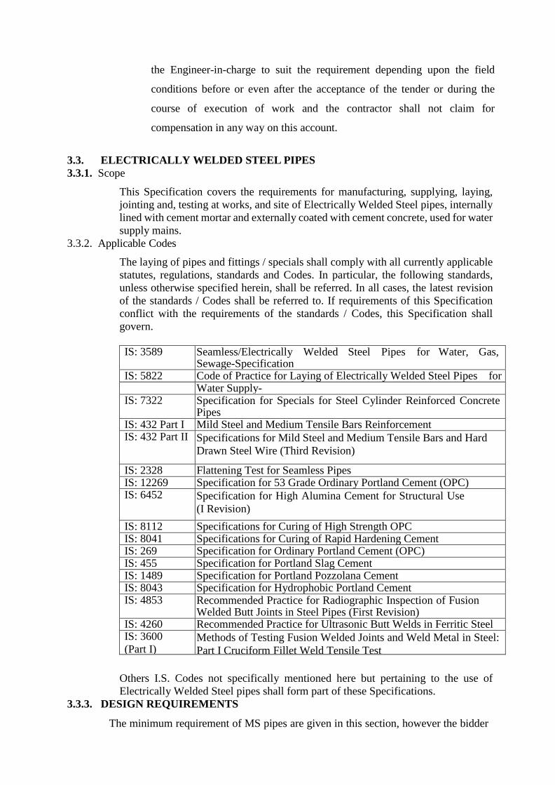
the Engineer-in-charge to suit the requirement depending upon the field
conditions before or even after the acceptance of the tender or during the
course of execution of work and the contractor shall not claim for
compensation in any way on this account.
3.3. ELECTRICALLY WELDED STEEL PIPES
3.3.1. Scope
This Specification covers the requirements for manufacturing, supplying, laying,
jointing and, testing at works, and site of Electrically Welded Steel pipes, internally
lined with cement mortar and externally coated with cement concrete, used for water
supply mains.
3.3.2. Applicable Codes
The laying of pipes and fittings / specials shall comply with all currently applicable
statutes, regulations, standards and Codes. In particular, the following standards,
unless otherwise specified herein, shall be referred. In all cases, the latest revision
of the standards / Codes shall be referred to. If requirements of this Specification
conflict with the requirements of the standards / Codes, this Specification shall
govern.
IS: 3589 Seamless/Electrically Welded Steel Pipes for Water, Gas,
Sewage-Specification IS: 5822 Code of Practice for Laying of Electrically Welded Steel Pipes for
Water Supply- IS: 7322 Specification for Specials for Steel Cylinder Reinforced Concrete
Pipes IS: 432 Part I Mild Steel and Medium Tensile Bars Reinforcement IS: 432 Part II Specifications for Mild Steel and Medium Tensile Bars and Hard
Drawn Steel Wire (Third Revision)
IS: 2328 Flattening Test for Seamless Pipes IS: 12269 Specification for 53 Grade Ordinary Portland Cement (OPC) IS: 6452 Specification for High Alumina Cement for Structural Use
(I Revision)
IS: 8112 Specifications for Curing of High Strength OPC IS: 8041 Specifications for Curing of Rapid Hardening Cement IS: 269 Specification for Ordinary Portland Cement (OPC) IS: 455 Specification for Portland Slag Cement IS: 1489 Specification for Portland Pozzolana Cement IS: 8043 Specification for Hydrophobic Portland Cement IS: 4853 Recommended Practice for Radiographic Inspection of Fusion
Welded Butt Joints in Steel Pipes (First Revision) IS: 4260 Recommended Practice for Ultrasonic Butt Welds in Ferritic Steel IS: 3600
(Part I) Methods of Testing Fusion Welded Joints and Weld Metal in Steel:
Part I Cruciform Fillet Weld Tensile Test
Others I.S. Codes not specifically mentioned here but pertaining to the use of
Electrically Welded Steel pipes shall form part of these Specifications.
3.3.3. DESIGN REQUIREMENTS
The minimum requirement of MS pipes are given in this section, however the bidder
is required to design the pipe as per provisions of IS 5822 and other applicable IS codes
with upto date amendments.
3.3.4. Material
Steel
The steel used shall be Fe 410 for manufacturing the pipes and specials shall conform
to IS: 2062. The quality of steel, chemical composition and tensile strength of the
steel plates shall be as specified in IS: 3589. The thickness of steel plates used for
manufacturing pipes shall conform to IS: 3589 or as specified. The thickness of steel
plates used shall in no case be less than that specified in IS: 3589.
Cement Mortar and Cement Concrete
The Cement Mortar and Cement Concrete used for pipes and specials shall conform
to the Specifications mentioned in Chapter 9 of Standard Specifications. The
maximum size of aggregate shall be one third the thickness of concrete cover inside
the steel pipe or 10 mm, whichever is less. The concrete mix shall have a minimum
cement content of 450 kg/m3 and a characteristic compressive strength of 25 N/mm2
at 28 days. The cement mortar shall have a minimum cement content of 600 kg/m3
and a characteristic compressive strength of 25 N/mm2 at 28 days.
Reinforcement
All cage reinforcement used in the pipes and specials shall conform to IS: 432 (Part-
1) or IS: 432 (Part-2).
Welding Electrodes
All electrodes used for welding of steel plates shall conform to IS: 814.
3.3.5. Length
The pipes shall be manufactured in lengths of 10-12 m, unless otherwise specified
or agreed to between the MPJNM and the manufacturer, for ease in handling.
3.3.6. Joints and Ends
Pipe sections shall be of swelled and plain ends suitable for swelled jointing. The
dimensions of sleeves shall be as specified in IS: 3589. Other relevant Specifications
with respect to joints and ends, as per IS: 3589 shall also be applicable.
3.3.7. Tolerances
The tolerances over dimensions of pipes for different diameters of pipes shall be as
specified in IS: 3589 and no negative tolerance in pipe thickness shall be accepted.
3.3.8. Manufacture
Pipes shall be made from steel plates by butt welding spirally. Pipes shall be of
specified nominal diameter after internal lining with 12 mm thick cement mortar as
per Specifications.
Prior to welding, edges of plates shall be prepared suitably. Prior to welding, the
plates shall be fitted closely and during welding they shall be held firmly. Welding
shall be done so that there shall be thorough fusion and complete penetration.
The ends of the steel pipes shall be perfectly vertical to its longitudinal axis.
3.3.9. Welding
For manufacturing of the steel pipes, any of the following types of welding shall be
adopted as per IS: 3589.
• Automatic submerged arc welding.
• Electric resistance welding.
The welding of pipes in the field and testing should comply with IS: 816.
Plates shall be held in the correct position. Abutting edges shall be properly squared.
Each deposited layer of the welded metal in the fusion welding process shall be
thoroughly cleaned before additional weld metal is supplied to coincide with the
centre line of joint and the finished joint shall be free from all defects.
All welds shall have complete fusion with the base metal and shall be free from
cracks, oxides, slag inclusion and gas pockets.
If welding is stopped for any reason, special care shall be taken when welding is
resumed to obtain complete penetration between weld metal, plate and weld metal
previously deposited. Three percent of all seams of pipes welded in the fabrication
shop shall be Radio graphed (as per IS: 4853) to render visible inspection of any
internal defects such as blow holes, slag inclusion or cracks. If any defects are
detected the metal at the location shall be chipped out and rewelded. In addition to
Radiography of the joints, 100 percent testing by ultrasonic equipment (as per IS:
4260) shall also be included in welding tests. Any defects found out shall be rectified
free of cost. Welds found deficient in quality shall be removed by chipping or
melting and remade as per Specifications. Chipping or cutting the weld shall not
extend to the base metal.
Sample welds shall be submitted for testing. The weld joints shall be tested in
accordance with the procedure laid down in IS: 3600 (Part-I)-1985, as specified in
IS: 5822. Approval of such tests shall be required prior to welding of the pipe.
Manual welding of special sections and fittings will be permitted when it is
impracticable to use an automatic welding machine.
Final welding of closure gaps for buried pipes shall be done after intermediate pipes
have been backfilled.
3.3.10.Radiograph of welded joints
Soon after welding, each longitudinal / spiral and circumferential welded length, the
minimum length of the weld at random for each pipe shall be radiographed to detect
welding defects, as per the requirements of IS 4853 and as directed by Engineer.
This sampling will be at random to ensure 100% coverage of junctions of
longitudinal / spiral and circumferential joints. If the results of such radiography fail
to conform to the requirements, the Contractor shall carry out at his expense 100 %
radiography test for the pertinent pipe as directed and fully satisfying the Engineer.
The percentage testing of radiography is as follows:
Pipes and Specials manufactured at Mill / Factory - 10%
Field joints welded at site - 5%
The weld ripples or weld surface irregularities and slag etc., on both inside and
outside shall be removed by any suitable mechanical process to a degree such that
resulting radiographic contact due to any remaining irregularities cannot mark or be
confused with that of objectionable defect. The radiograph shall be made in strict
accordance with the latest requirements and as per the latest and most efficient
technique either with X-ray or gamma ray equipment. The safety requirements
during radiography shall be in accordance with IS 2598.
The radiographs are to be marked in such a way that the corresponding portion of
the welded seam and the welder can be readily identified. All radiographs will be
reviewed by the Engineer to identify the defects and determine those which requires
rectification. Defects that are not acceptable shall be removed by chipping, grinding
or flame gouging to sound metal and the resulting cavities shall be welded. After
rectification, the joint is to be radiographed again to prove the quality of the repair.
The radiographs will be judged as acceptable or unacceptable by the Engineer based
on the latest standards prescribed by relevant Indian Standard specification.
All X-rays shall be taken with equipment and by personnel of the Contractor. Films
shall be developed within 24 hours of exposure and be readily accessible at all times
for inspection by the Engineer. The Contractor shall provide for the use of the
Engineer suitable X-ray viewing equipment. X-ray films shall be properly
maintained by the Contractor. A complete set of radiographs and records as
described in IS: 2595, for each job shall be retained by the Contractor and shall be
handed over to the Engineer on completion of the Contract. All films shall be
identified by the number and chart prepared indicating location of any work
associated with the pipe erection and such inspection shall be performed by the
Radiographer at the discretion of the Engineer.
Radiographic Inspection of welded joints:
All welded joints to be radiographed shall be examined in accordance with -
IS 2595 - Code of Practice for Radiographic Testing
IS 4853 - Recommended Practice for Radiographic Examination of
Fusion Welded Butt – Joints in Steel Pipes
IS 2598 - Safety Code for Industrial Radiographic Practice.
Radiographers performing radiograph shall be qualified in accordance with SNT-
TC- 1A. Supplements and Appendices “Recommended Practice for Non-destructive
Testing Personnel Qualification and Certification” published by the American
Society for Non-destructive Testing as applicable for the technique and methods will
be used.
Final acceptance of radiographs shall be based on the ability to see the prescribed
penetrameter image and the specified hole.
Sections of welds that are shown by radiography to have any of the following types
of imperfections shall be judged unacceptable and shall be repaired.
Any type of crack, or zone of incomplete fusion or penetration, any elongated slag
inclusion which has length greater than 6 mm any group of slag inclusion in line that
have an aggregate length greater than thickness in a length of 12 times thickness,
except when the distance between the successive imperfections exceeds 6 L where
L is the length of the longest imperfection in the group, rounded indications in excess
of that specified by the acceptance standards given earlier.
3.3.11.Fabrication of specials
Specials such as bends, tapers, tees shall conform to IS: 7322. Specials shall be
fabricated by cutting plates of the specified thickness to the required shape obtained
by developing the form of specials on ground. Stiffeners shall be provided wherever
necessary. Abutting profiles shall be obtained using templates which guide the
cutting torches as to obtain a uniform cut. No hand cutting shall be permitted.
Specifications for the using and testing of the plates, electrodes, welding, cleaning
etc., shall be the same as for the straight pipes.
1. Horizontal and vertical curves
Standard bends of deviations from 5 degree to 90 degrees shall be fabricated out
of steel plates. The cut pieces shall as far as possible be placed at the end of pipes
joined in the factory. The angle of the cut pieces shall be made so as to obtain
the necessary curvature. In case of deviations differing from the standards, cut
pieces shall be made to suit the particular site conditions. Length of the cut pieces
shall be in line with standard specials. The vertical cuts shall be so adjusted as to
conform to the proposed longitudinal section. Distance pieces may be used to
obtain the above conditions.
2. Tapers and Tees
Tapers and tees shall be fabricated with one or more stocks, each stock having a
stiffening ring fixed circumferentially in the centre. The stiffener rings shall be
made of M.S. Plate of approved thickness.
3. Provisions for valves
Provisions in the form of stubs of required diameter shall be fabricated by the
Contractor and shall be fixed to the pipeline after cutting pipe with necessary pad
plates.
3.3.12.Cement Concrete and Mortar Lining of Pipes and specials.
Preparation of surface before lining or coating.
The surface of pipe to be lined or coated with cement mortar or cement concrete
shall be clean. Any loose rust, loose millscale, dirt, debris, oil, grease and other
detrimental materials present shall be removed by mechanical means.
Cement Concrete lining for inside of steel pipes and specials and mortar coating
outside.
Cement Concrete shall be composed of cement, coarse and fine aggregates and water
well mixed and of proper consistency to obtain a dense, homogeneous lining that
will adhere firmly to the pipe surface. Thickness of cement concrete lining inside the
pipe shell shall be of 12 mm and that of the mortar lining outside the pipe shell shall
be 30 mm thick or as per relevant IS specifications.
3.3.13.Mixing
The concrete for internal lining shall be mixed as per provisions of IS code
3.3.14.Cover
The clear cover to the reinforcement whether steel cylinder or cage shall not be less
than 9 mm for lining and 12 mm for coating.
3.3.15.Reinforcement
Wire fabric shall be used for external reinforcement. It shall be 50 x 50 mm steel
wire mesh, 13 gauge each way, and conform to IS: 432 (Part-1) or IS: 432 (Part-2).
The reinforcement cage for the pipes shall extend throughout the pipe barrel and
shall consist of spirals or rings and straights. The spirals or rings shall be circular in
shape and shall be either wound round the steel pipe shell itself or wound round
collapsible frame or drums and then slipped on the steel pipe shell. The fabric shall
be wrapped on the shell by tack welding. The outer cage reinforcement for swelled
end portions of the pipe shall be wound on them at the time of laying. Minimum
reinforcement in the lining shall not be less than three percent of the quantity of steel
pipe shell. Splices shall be made by welding or other suitable means. The fabric shall
be wrapped on the shell by tack welding.
3.3.16.Equipment for lining of Pipes
1. Straight sections of pipe shall be lined by use of a spinning machine specifically
designed to suit for the purpose of rotating the section and centrifugally applying
cement concrete lining to the interior of steel pipe. Mechanical feeding is
preferable.
2. The Contractor shall plan for installation of sufficient number of spinning
machines/equipment for inside lining and outside coating of pipes, and the
proposed factories. If during the progress of works, it becomes necessary for
transporting of plates/pipes from one factory to the other for fabrication/lining
and or coating due to inadequate number of machines or breakdowns or to meet
progress targets, the Contractor should arrange for such transportation of pipes
from one factory to the other at his own cost.
Concreting lining and mortar coating of pipes
1. This shall be done generally in two stages to give the required thickness of the
barrel.
2. In the first stage concreting shall be done inside the pipe shell and in the second
stage placing of the mortar is done outside the pipe shell. Placing of concrete
inside the steel pipe shell shall always be done at the manufacturer’s works and
consolidated by spinning, vibrating, spinning combined with vibrations or other
appropriate mechanical means whilst the placing of mortar outside the steel pipe
shell shall be done later either at the manufacturer’s works or at site.
3. Mortar coating outside the steel pipe shell shall not commence before the expiry of three days after the completion of concreting inside, unless otherwise it is established that the concrete lining inside has attained works cube strength of not
less than 110 kg/cm2, earlier than this period. During this entire period the concrete inside the steel pipe shell shall be under curing. The mortar outside the steel pipe shell shall be either vibrated or applied under pressure.
4. In the case of pipes with plain ends or slip-in type ends, the portions that should
be left exposed without concreting or mortar lining shall be mutually agreed to
between the purchaser and the manufacturer.
Lining of specials
1. Whenever practicable, specials shall be made form cut lengths of matured lined
straight pipes. The lining shall be cut back from the end to ends to be bevelled
and welded for a sufficient distance to ensure that any of the concrete lining
which is intended to remain as part of lining shall not suffer damage by the
cutting or welding process. The concrete lining shall be made good by rendering
by hand.
2. Hand rendering of specials shall consist of freshly mixed concrete of a mixture
equivalent to that of the lining being repaired, and shall be thoroughly compacted
and finished to a smooth surface of the correct form.
Cement concrete shall be used both for lining and coating of specials. The
thickness of lining and coating shall be 25 mm. Specials shall have the nominal
dia as that of the connecting pipe after lining. Specifications for lining and
coating of specials shall be as that of the straight pipes.
3. The application of cement concrete lining to bends, or specials sections whose
shapes preclude other process of lining shall be by mechanical placement,
pneumatic placement or hand trowelling finished to produce a smooth dense
surface. Debris shall be removed as necessary, permitting the application of the
lining to a clear surface.
4. Thickness shall be as required for spun lining of straight sections except that it
may be varied by feathering or filleting to affect system lining with adjoining
sections of pipe and thickness of lining.
Determination of thickness of lining
Lining thickness shall be determined on the freshly lined pipes, at intervals frequent
enough to assure compliance. Thickness of lining may be determined by means of a
steel pin not larger than 1.5 mm in diameter or on a hardened concrete or mortar by
means of a non-destructive measurement process. The lining shall be measured at
four equidistant points on two cross sections of the barrel at each end of the pipe or
fittings. The first set shall be at least 200 mm from the respective ends of the pipe or
fitting. The second set shall be made as far into the interior of the pipe or fitting as
can be readily reached without injuring the lining.
Curing
1. After completion of concreting or mortar lining, the concrete or mortar shall be
kept wet by any suitable means such as immersion in water, covering by wet
gunny bags, or by mechanical sprinklers, for a period of not less than 14 days
when cement conforming to IS: 269 or IS: 455 or IS: 1489 or IS: 8043 or IS:
6909 is used; not less than 7 days when cement conforming to IS: 8041 or IS:
8112 is used; not less than 3 days when cement conforming to IS: 6452 or IS:
12269 is used; and not less than 21 days when cement conforming to IS: 12330
is used.
2. Non-pressure steam curing may be permitted provided the requirements of non-
pressure steam curing are fulfilled. For non pressure steam curing, the pipe shall
be subjected to the action of thoroughly saturated steam at a temperature of 38
to 54 degree C for a period of not less than 24 hours or for such additional time
as may be necessary to enable the pipe to meet the strength requirements.
Repair of defective or Damaged Areas of lining
Defective or damaged areas of linings may be patched by cutting out the defective
or damaged lining to the metal so that the edges of lining not removed are
perpendicular or slightly undercut. A fresh mix of concrete or mortar equivalent to
that of the lining being repaired shall be prepared. The cut-out area and the adjoining
lining shall be thoroughly wetted, and the concrete or mortar applied to the inside or
outside respectively and trowelled smooth with the adjoining lining. After any
surface water has evaporated, but while the patch is still moist, it shall be cured as
specified.
Protection of work
The lined pipe and fittings shall be protected from extreme heat due to direct sun
rays, from impact of rainfall, and from freezing temperatures until the linings have
cured sufficiently to withstand these conditions.
3.3.17.Workmanship
All pipes shall be cleanly finished free of cracks, surface flaws, laminations and all
other defects. They shall be cylindrical, concentric and straight in axis. The ends
shall be accurately cut and shaped for welds. The ends shall be square with the axis
of the pipe. The repair of minor defects by welding or otherwise shall be permitted
only after obtaining the prior permission from the Engineer in writing. No heating
shall be permitted.
3.3.18.Handling of pipes and specials.
During manufacturing and during the entire period of the application of concrete or
mortar lining protection and the curing thereof, the section shall be carefully
supported and handled so as to avoid injury to the fresh lining. If a pipe section must
be rolled or otherwise moved, such operation shall be done slowly and with every
reasonable precaution against damage. Any portion of the lining, coating that may
become damaged shall be cut and replaced.
During delivery, all sections shall be handled by such means and in such a manner
that no distortion or damage is done to the protection or to the section as a whole.
3.3.19. Laying of pipes
Pipes shall be laid in accordance with standard laying procedures.
All pipes shall be laid true to line and level and on pedestals wherever required, the
joints strictly conforming to welding Specifications. Joints shall be finished in a
workman like manner and shall prove to be sound and water tight. The field welding
shall be carefully carried out so as to induce the minimum heat distortion and local
hardness in steel.
In addition, the provisions of IS: 5822 shall also be applicable.
3.3.20.Field Jointing of Insides and outsides of Concrete lined pipes.
Cement mortar shall be used for lining of inside and outside lining of joints. It shall
be of the same Specifications as those of outside mortar coating of pipes, cement
mortar lining for inside and outside of field joints shall be done only after testing the
pipe line as per Clause 15.5.17.3.
Jointing Inside
For the inside lining of field joints, wire fabric of 50 x 50 mm steel mesh, 13 gauge
each way, shall be provided. Inside joints of mortar lined pipe shall be plastered with
cement mortar and finished off smooth with the inside surface of the pipe by
trowelling or by other equipment means. Before placing the joint mortar material
against the surface of the lining, these surfaces shall be carefully cleaned and wetted
to ensure good bond between the lining and joint mortar. The field joint shall be cured
for a minimum of 14 days. In any case the pipe line shall not be put into serve until
the mortar has cured for a minimum of 24 days. The joints shall be finished off smooth
with the inside surface of the lining by trowelling.
Jointing Outside
1. For this item, the joints have been classified into two groups: • Those coming under water logged area • Those coming in other area.
2. Joints under waterlogged areas: These joints shall be done with Cement Mortar
1:2 with two layers of M.S. 50 mm x 50 mm x 13 gauge weld mesh and the
thickness of mortar shall be 50 mm thick and a suitable water proofing
compound shall also be used.
3. Joints coming in other areas: This shall be done with Cement mortar 1:2, 25 mm
thick with one layer of 50 mm x 50 mm x 13 gauge wire fabric reinforcement.
4. Outside field joints shall be coated with cement mortar retained by suitable forms
so as to bridge the joints. The mortar shall be compacted within the form to
produce a dense coating without voids. The joint coating shall be kept moist for
a minimum or 14 days.
3.3.21.Fixing of fixtures
Contractor has to fix the required number of fixtures at proper locations as per the
approved Drawings and the instructions of Engineer. The fixtures shall be fixed to
the flanges by bolts, nuts and washers with necessary fireplay insertions etc. All
types of fixtures and necessary equipment required for fixing these fixtures shall be
arranged by the Contractor at his own cost.
3.3.22.Testing of Pipe line
Mechanical Test (Tensile Test)
Tensile test shall be carried out as specified in IS: 1894:1972. The tensile strength
and percentage elongation of pipes shall not be less than the values specified in the
table below. The percentage elongation shall be determined on a gauge length of 5.65 times of square root of original cross sectional area of the specimen (So).
Steel grade Tensile strength MPa (min) Percentage elongation (min)
Fe 330 330 20 Fe 410 410 18 Fe 450 450 12
Hydrostatic Testing at Works
1. Each straight pipe section whose ends are in plane at right angle to the pipe axis
shall be tested hydrostatically before the pipe is coated, wrapped or lined, as per
IS: 3589. The pipes shall withstand the test pressure without showing any signs
of weakness, leak or sweating. The test shall be carried out in the presence of the
Engineer and as per Specifications. The required pressure should be maintained
for at least 2 minutes for inspection purposes. The pipes shall be fitted with an
accurate pressure gauge approved by the Engineer.
2. The hydraulic test pressure shall be the pressure calculated from the formula
P=2St/D except that the maximum test pressure shall not exceed 5 MPa.
Where P = Test pressure in MPa
S = Stress in MPa which shall be taken as 40 % of specified minimum tensile
strength t = Specified thickness in mm
D = Specified outside diameter in mm
3. In this test, no hammering shall be permitted. Any section showing more than
one leak for each 1.5 metres of welded seam or more than 2.5 percent of the total
lengths of welded seam will be rejected. Stopping leaks by means of caulking
tools shall not be permitted. In sections showing less than one leak for each 1.5
meters of welded seam and not more than 2.5 percent of the total lengths of
welded seam, the leaks shall be repaired by chipping the weld and rewelding,
after obtaining the permission of the Engineer in writing. All such sections shall
be clearly indicated in the logbook for reference. The repaired pipe should be
retested hydrostatically for specified pressures. If on retest a pipe shows any leak
in the welded seams it will be rejected. Accepted pipe sections shall be marked
with legible marks of identification. This test is compulsory on all straight pipes.
Testing at site
1. After completing the installation of pipe line, or a section of the line and welding
of joints, a hydrostatic pressure test of the line shall be made before giving the
lining and coating to the exposed joints. The hydrostatic pressure shall be
maintained as per Clause 11.2.1 of IS: 5822:1994, during which time the pipe
shall not show any sign of sweating or oozing or spotting of water at the joints
or any part. If a drop in pressure occurs the quality of water added in order to re-
establish the test pressure, should be carefully measured. This should not exceed
0.1 litre per mm of pipe diameter per km of pipe line per day for each 30 m head
of pressure applied.
2. If the pressure measurements are not made at the lowest section, an allowance
should be made for the static head between the lowest point and the point of
measurement to ensure that the maximum pressure is not exceeded at the lowest
point. Any defective joint or part shall be repaired and retested in the presence
of the Engineer. The Contractor shall make his own arrangements for water for
field testing. Water if supplied by department will be charged at non- domestic
rates prevalent at the time of supply. The pipe line shall be tested in stretches of
not exceeding 2 km in length. This field hydraulic test is mandatory. This clause
is not negotiable.
3.3.23.Measurements
The net length of pipes of specified thickness as laid or fixed shall be measured
nearest to cm and weight shall be worked out . The portion of the pipe at the joints
shall not be included in the length of pipe work.
Excavation, refilling, shoring and timbering in trenches masonry or concrete pillars
and thrust blocks wherever required is inclusive.
4 Excavation and preparation of trenches for laying underground pipeline
4.1 The trench shall be so dug that the pipe may be laid to the required alignment and at
required depth. For road cutting and restoration of concrete/ BT roads, estimates are
based on conventional method. However, as directed by the Engineer in Charge, the
contactor is required to complete this work by either (i) using concrete cutter/ trenching
machine, or (ii) using trenchless technology. Roads are required to be restored as per
specifications of the concerned department or as directed by the engineer in charge.
When the pipeline is under a roadway, a minimum cover of 1.2 m shall be provided, in
other cases the minimum cover of 0.9 m above the crown of the pipe shall be provided,
if due to the any condition the pipe not laid at prescribed depth deduction will be made
as per UADD ISSR May 2012. The trench shall be shored, wherever necessary and kept
dry so that the workman may work therein safely and efficiently. Under roadway and
places where it is not possible to lay pipes up to required depth or laid open on ground
should be encased all round with the 1:2:4 ( M15) cement concrete.
4.2 Recovery of other serviceable material:-
All serviceable materials such as wood work, bricks, masonry etc. recovered during
the operation of cleaning or excavations, which, in the opinion of the Engineer-in-
Charge are suitable for reuse in restoring the surface, shall be separately stacked and
disposed-of as directed by Engineer-in-Charge.
4.3 Dewatering:-
Dewatering shall be carried out by the contractor, wherever necessary. The discharge
of the trench dewatering pumps shall be conveyed either to drainage channels or to
natural drains and shall not be allowed to spread over in the vicinity of work place.
Trenching:-
The trench shall be so dug that the pipe may be laid to the required alignment and at
required depth. For road cutting and restoration of concrete/ BT roads, estimates are based
on conventional method. However, as directed by the Engineer in Charge, the contactor is
required to complete this work either (i) with concrete cutter/ trenching machine, or (ii)
using trenchless technology. When the pipeline is under a roadway, a minimum cover of
1.2 m under major roads shall be provided, in other cases the minimum cover of 0.9 m
above the crown of the pipe shall be provided, if due to the any condition the pipe are not
laid at prescribed depth, deduction will be made as per UADD ISSR May 2012. The trench
shall be shored, wherever necessary and kept dry so that the workman may work therein
safely and efficiently. Under roadway and places where it is not possible to lay pipes up
to required depth or laid open on ground shall be encased all round with the 1:1.5 :3 (
M15) cement concrete.
4.4 Preparation of bottom of trench:-
The bottom of the trench shall be properly trimmed to permit even bedding of the
pipeline. The curvature of the bottom of the trench should match the curvature of the
pipe as far as possible, subtending an angle of 120o
at the centre of the pipe. Where
rock or boulders are encountered, the trench shall be trimmed to a depth of at least
100 mm below the level at which the bottom of the pipe is to be laid and filled to a
like depth with non- compressible material like sand or crusher dust or moorum of
adequate depth to give the curved seating.
4.5 Special foundation in poor soil:-
Where the bottom of the trench at subgrade is found to consist of material, which is
unstable to such a degree that in the opinion of Engineer-in-Charge it cannot be removed
and replaced with an approved material thoroughly compacted in place to support
the pipe properly, a suitable foundation for the pipe, consisting of piling, timbers
or other materials, in accordance with the direction of the Engineer-in-Charge, shall be
constructed.
4.6 Excavation in hard rock by blasting:-
Blasting for excavation shall be done only when the contractor obtains the license for
the same and only when proper precautions are taken for the protection of persons and
property. The hours of blasting shall be fixed by the Engineer-in-Charge. The
procedure of blasting shall conform to the requirement of licensing authority. The
excess excavation by blasting shall be filled up by 1:4:8 cement concrete. The
contractor shall have to make his own arrangement for procurement and storing of
explosives required for blasting.
Rubble available from excavation of hard rock, shall be the property of the contractor,
for which recovery of INR 65/- per cum of the quantity of hard rock excavated shall be
made from his running account bills.
4.7 Braced and sheeted trenches:-
Open-cut trenches shall be sheeted and braced as required by Engineer-in-Charge and
as may be necessary to protect life and property or the work. When closed sheeting is
required, it shall be so driven as to prevent adjacent soil from entering the trench either
below or through such sheeting.
4.8 Stacking of excavated material:-
All excavated materials shall be stacked in such a manner that it does not endanger the
work and avoids obstructing footpaths and roads, hydrants under pressure, surface
boxes, fire, or other utility controls shall be left unobstructed and accessible until the
work is completed. Gutters shall be kept clear or other satisfactory provisions made for
street drainage and natural watercourses shall not be obstructed.
4.9 Barricades, guards and safety provisions:-
To protect persons from injury and to avoid damage to property, adequate barricades,
construction signs, torches, red lanterns and guards, as required, shall be placed and
maintained during the progress of the construction work and until it is safe for traffic to
use the roadway. All materials, piles, equipments and pipes, which may obstruct traffic,
shall be enclosed by fences or barricades and shall be protected by proper lights when
visibility is poor. The rules and regulations of the local authorities regarding safety
provisions shall be observed.
4.10 Maintenance of traffic and closing of streets:-
The work shall be carried out in such manner that it causes the least interruption to
traffic, and the road/street may be closed in such a manner that it causes the least
interruption to the traffic. Where it is necessary for traffic to cross open trenches,
suitable bridges shall be provided. Suitable signs indicating that a streets is closed shall
be placed and necessary detour signs for the proper maintenance of traffic shall be
provided.
4.11 Structure Protection:-
Temporary support, adequate protection and maintenance of all underground and surface
structures, drains, sewers and other obstruction encountered in the progress of the work
shall be furnished under the direction of the Engineer-in-Charge. The structures, which
may have been disturbed, shall be restored upon completion of the work.
4.12 Protection of property and surface structures:-
Trees, shrubbery fences, poles and all other property and surface structure shall be
protected unless their removal is shown on the drawings or authorized by the Engineer-
in-Charge. When it is necessary to cut roots and tree branches such cutting shall be
done under the supervision and direction of the Engineer-in-Charge.
4.13 Avoidance of the Existing Service:-
As far as possible, the pipeline shall be laid below existing services, such as water and
gas pipes, cables, cable ducts and drains but not below sewers, which are usually laid at
great depth. If it is unavoidable, pipeline should be suitably protected. A minimum
clearance of 150 mm shall be provided between the pipeline and such other services.
Where thrust or auger boring is used for laying pipeline across road, railways or other
utilities, larger clearance as required by the concerned authority shall be provided.
Adequate arrangements shall be made to protect and support the other services during
laying operations. The pipeline shall be so laid as not to obstruct access to the other
services for inspection, repair and replacement. When such utilities are met with during
excavation the authority concerned shall be intimated and arrangements made to support
the utilities in consultation with them.
4.14 Restoration of sewerage system: If the sewer lines are coming in the way of pipeline
alignment, it shall be properly restored either by constructing manholes on both sides
and connecting it with similar sewer line, so as not to disrupt the services of the
sewerage system or by laying the pipeline below or above the sewerage system as per
the directions of Engineer-in-Charge.
4.15 Preparation of Formation for Sections of pipe line to be laid above Ground:-
Formation should be prepared by cutting high grounds and filling in low areas. Care has
to be taken while fixing the alignment and gradient of the pipeline, to balance the
cutting and filling quantities, as far as possible, with minimum of lead. Care should also
be taken to ensure that pipe rests fully either on cutting or on bank.
4.16 Disposal of surplus material:
Excavated material in excess than required for backfilling the trenches, shall be disposed
off as per the directions of Engineer-in-Charge. Surplus excavated stuff available at one
section shall be used for back filling at other reaches, wherever required.
4.17 Allowable Removal of Pavement
Pavement and road surfaces may be removed as a part of the trench excavation, and the
amount removed shall depend upon the width of trench specified for the installation of the
pipe and the width and length of the pavement area required to be removed for the
installation of gate valves, specials, man-holes or other structures. The width of pavement
removed along the normal trench for the installation of the pipe shall not exceed the width
of the trench specified by more than 150 mm on each side of the trench. The width and
lengths of the area of pavement removed for the installation of gate valves, specials, man-
holes or other structures shall not exceed the maximum linear dimensions of such
structures by more than 150 mm on each side. Wherever in the opinion of the authority,
existing conditions make it necessary or advisable to remove additional pavement, it shall
be removed as directed by the authority.
4.18 Replacement of Pavements and Structures
All pavements, paved footpaths, curbing, gutters, shrubbery, fences, poles, sods or other
property and surface structures removed or disturbed as a part of the work shall be restored
to a condition equal to that before the work began, furnishing all labour and materials
incidental thereto. In restoring the pavement, sound granite blocks, sound brick or asphalt
paving blocks may be re-used.
4.19 Cleaning-Up
All surplus water main materials and all tools and temporary structures shall be removed
from the site as directed by the authority. All dirt, rubbish, and excess earth from the
excavation shall be hauled to a dump and the construction site left clean to the satisfaction
of the authority.
4.20 Extra material required for back filling:
If in any case, it is required to bring the soil for back filling from outside, it should be
of good quality and should not have chemicals e.g. sulphates, chlorides & conductivity
etc., which may cause corrosion to pipes, specials and other structures, beyond the
permissible limits.
4.21 Road, rail and river crossings: -
The mode of laying the pipeline, crossing road, railway or river in the entire project
shall be determined so as to satisfy the requirement of the authority concerned. Cost of
all such crossings shall be included in the rates and no extra payment shall be made on
that account. Laisoning with the concerned authorities will be under the scope of the
contractor, only the fee/charges, if any payable to the concerned department/authority for
grant of permission will be paid/reimbursed by MPJNM.
Managing Director
Madhya Pradesh Jal Nigam
Maryadit Vindhyachal Bhawan,
Bhopal
CHAPTER - 1.3
BRIEF SPECIFICATIONS CLEAR WATER PUMPING MAIN
WORK
1. BRIEF SCOPE OF WORK:
The Clear Water Pumping Main shall be provided for conveying water from Clear
Water Sump of Treatment Plant to MBR/IPS and various OHTs/GLRs as given below.
Providing, laying & jointing of Clear water Pumping main pipes as per relevant IS
specification with upto date amendments i/c flow meters, valves, sluice valves, air
valves, scour valves, chambers, thrust block, crossings, specials & accessories etc
complete for a total length of 44.48 km ( Including MBR- 1 & 2 Sumps)
DI K9 pipe - 150 mm dia - 13000 m
DI K9 pipe - 200 mm dia - 26279 m
DI K9 pipe - 250 mm dia - 3500 m
DI K9 pipe - 350 mm dia - 500 m
MS pipe- 1300 mm dia - 1200 m
Allied Works: All works necessary for providing, laying, jointing, testing,
commissioning and O&M of above g r a v i t y / pumping mains shall fall under the
scope of works including surge protection works, if any including fixing of Electro
Magnectic Flow Meters at suitable places.
The main items of allied works are providing, fixing, jointing, testing, commissioning
etc. of butterfly valves, reflux valve, air valves, scour valves, its chambers,
manholes, cross drainage works, thrust blocks, anchor blocks, expansion joints etc.
complete.
2. LAYOUT DRAWINGS OF PUMPING MAINS:-
The contractor shall have to carry out confirmatory survey and submit the detailed
layout drawing, sufficient to show the details as mentioned below-
a. R.L. of ground, invert level of pipes and H.G.L. at every 30 m interval.
b. Location of horizontal and vertical bends.
c. Degree of bends, degree or radius of curves, tangent distance for curves.
d. Location and covering length of all valves and other appurtenances.
e. Details and description of all specials.
f. Location and size of supporting pillars, bridges and culverts to cross the
waterways.
g. Location and sizes of thrust blocks and anchor blocks.
h. Location and sizes of valve chambers.
i. Details, dimensions and plan including complete description of
expansion joints and flanges.
The layout plan submitted by the contractor, can be altered or modified by the
Engineer-in-charge to suit the requirement depending upon the field conditions
before or even after the acceptance of the tender or during the course of
execution of work and the contractor shall not claim for compensation in any
way on this account.
3.1. ELECTRICALLY WELDED STEEL PIPES
3.1.1. Scope
This Specification covers the requirements for manufacturing, supplying, laying,
jointing and, testing at works, and site of Electrically Welded Steel pipes, internally
lined with cement mortar and externally coated with cement concrete, used for
water supply mains.

3.1.2. Applicable Codes
The laying of pipes and fittings / specials shall comply with all currently applicable
statutes, regulations, standards and Codes. In particular, the following standards,
unless otherwise specified herein, shall be referred. In all cases, the latest revision
of the standards / Codes shall be referred to. If requirements of this Specification
conflict with the requirements of the standards / Codes, this Specification shall
govern.
IS: 3589 Seamless/Electrically Welded Steel Pipes for Water, Gas,
Sewage-Specification IS: 5822 Code of Practice for Laying of Electrically Welded Steel Pipes for
Water Supply- IS: 7322 Specification for Specials for Steel Cylinder Reinforced Concrete
Pipes IS: 432 Part I Mild Steel and Medium Tensile Bars Reinforcement IS: 432 Part II Specifications for Mild Steel and Medium Tensile Bars and Hard
Drawn Steel Wire (Third Revision)
IS: 2328 Flattening Test for Seamless Pipes IS: 12269 Specification for 53 Grade Ordinary Portland Cement (OPC) IS: 6452 Specification for High Alumina Cement for Structural Use
(I Revision)
IS: 8112 Specifications for Curing of High Strength OPC IS: 8041 Specifications for Curing of Rapid Hardening Cement IS: 269 Specification for Ordinary Portland Cement (OPC) IS: 455 Specification for Portland Slag Cement IS: 1489 Specification for Portland Pozzolana Cement IS: 8043 Specification for Hydrophobic Portland Cement IS: 4853 Recommended Practice for Radiographic Inspection of Fusion
Welded Butt Joints in Steel Pipes (First Revision) IS: 4260 Recommended Practice for Ultrasonic Butt Welds in Ferritic Steel IS: 3600
(Part I)
Methods of Testing Fusion Welded Joints and Weld Metal in Steel:
Part I Cruciform Fillet Weld Tensile Test
Others I.S. Codes not specifically mentioned here but pertaining to the use of
Electrically Welded Steel pipes shall form part of these Specifications.
3.1.3. Material
Steel
The steel used shall be Fe 410 for manufacturing the pipes and specials shall
conform to IS: 2062. The quality of steel, chemical composition and tensile
strength of the steel plates shall be as specified in IS: 3589. The thickness of steel
plates used for manufacturing pipes shall conform to IS: 3589 or as specified. The
thickness of steel plates used shall in no case be less than that specified in IS: 3589.
Cement Mortar and Cement Concrete
The Cement Mortar and Cement Concrete used for pipes and specials shall
conform to the Specifications mentioned in Chapter 9 of Standard Specifications.
The maximum size of aggregate shall be one third the thickness of concrete cover
inside the steel pipe or 10 mm, whichever is less. The concrete mix shall have a
minimum cement content of 450 kg/m3 and a characteristic compressive strength
of 25 N/mm2 at 28 days. The cement mortar shall have a minimum cement content
of 600 kg/m3 and a characteristic compressive strength of 25 N/mm2 at 28 days.
Reinforcement
All cage reinforcement used in the pipes and specials shall conform to IS: 432
(Part- 1) or IS: 432 (Part-2).
Welding Electrodes
All electrodes used for welding of steel plates shall conform to IS: 814.
3.1.4. Length
The pipes shall be manufactured in lengths of 10-12 m, unless otherwise specified
or agreed to between the MPJNM and the manufacturer, for ease in handling.
3.1.5. Joints and Ends
Pipe sections shall be of swelled and plain ends suitable for swelled jointing. The
dimensions of sleeves shall be as specified in IS: 3589. Other relevant
Specifications with respect to joints and ends, as per IS: 3589 shall also be
applicable.
3.1.6. Tolerances
The tolerances over dimensions of pipes for different diameters of pipes shall be as
specified in IS: 3589 and no negative tolerance in pipe thickness shall be accepted.
3.1.7. Manufacture
Pipes shall be made from steel plates by butt welding spirally. Pipes shall be of
specified nominal diameter after internal lining with 12 mm thick cement mortar
as per Specifications.
Prior to welding, edges of plates shall be prepared suitably. Prior to welding, the
plates shall be fitted closely and during welding they shall be held firmly. Welding
shall be done so that there shall be thorough fusion and complete penetration.
The ends of the steel pipes shall be perfectly vertical to its longitudinal axis.
3.1.8. Welding
For manufacturing of the steel pipes, any of the following types of welding shall
be adopted as per IS: 3589.
• Automatic submerged arc welding.
• Electric resistance welding.
The welding of pipes in the field and testing should comply with IS: 816.
Plates shall be held in the correct position. Abutting edges shall be properly
squared. Each deposited layer of the welded metal in the fusion welding process
shall be thoroughly cleaned before additional weld metal is supplied to coincide
with the centre line of joint and the finished joint shall be free from all defects.
All welds shall have complete fusion with the base metal and shall be free from
cracks, oxides, slag inclusion and gas pockets.
If welding is stopped for any reason, special care shall be taken when welding is
resumed to obtain complete penetration between weld metal, plate and weld metal
previously deposited. Three percent of all seams of pipes welded in the fabrication
shop shall be Radio graphed (as per IS: 4853) to render visible inspection of any
internal defects such as blow holes, slag inclusion or cracks. If any defects are
detected the metal at the location shall be chipped out and rewelded. In addition to
Radiography of the joints, 100 percent testing by ultrasonic equipment (as per IS:
4260) shall also be included in welding tests. Any defects found out shall be
rectified free of cost. Welds found deficient in quality shall be removed by chipping
or melting and remade as per Specifications. Chipping or cutting the weld shall not
extend to the base metal.
Sample welds shall be submitted for testing. The weld joints shall be tested in
accordance with the procedure laid down in IS: 3600 (Part-I)-1985, as specified in
IS: 5822. Approval of such tests shall be required prior to welding of the pipe.
Manual welding of special sections and fittings will be permitted when it is
impracticable to use an automatic welding machine.
Final welding of closure gaps for buried pipes shall be done after intermediate pipes
have been backfilled.
3.1.9. Radiograph of welded joints
Soon after welding, each longitudinal / spiral and circumferential welded length,
the minimum length of the weld at random for each pipe shall be radiographed to
detect welding defects, as per the requirements of IS 4853 and as directed by
Engineer. This sampling will be at random to ensure 100% coverage of junctions
of longitudinal / spiral and circumferential joints. If the results of such radiography
fail to conform to the requirements, the Contractor shall carry out at his expense
100 % radiography test for the pertinent pipe as directed and fully satisfying the
Engineer.
The percentage testing of radiography is as follows:
Pipes and Specials manufactured at Mill / Factory - 10%
Field joints welded at site - 5%
The weld ripples or weld surface irregularities and slag etc., on both inside and
outside shall be removed by any suitable mechanical process to a degree such that
resulting radiographic contact due to any remaining irregularities cannot mark or
be confused with that of objectionable defect. The radiograph shall be made in strict
accordance with the latest requirements and as per the latest and most efficient
technique either with X-ray or gamma ray equipment. The safety requirements
during radiography shall be in accordance with IS 2598.
The radiographs are to be marked in such a way that the corresponding portion of
the welded seam and the welder can be readily identified. All radiographs will be
reviewed by the Engineer to identify the defects and determine those which
requires rectification. Defects that are not acceptable shall be removed by chipping,
grinding or flame gouging to sound metal and the resulting cavities shall be welded.
After rectification, the joint is to be radiographed again to prove the quality of the
repair. The radiographs will be judged as acceptable or unacceptable by the
Engineer based on the latest standards prescribed by relevant Indian Standard
specification.
All X-rays shall be taken with equipment and by personnel of the Contractor. Films
shall be developed within 24 hours of exposure and be readily accessible at all
times for inspection by the Engineer. The Contractor shall provide for the use of
the Engineer suitable X-ray viewing equipment. X-ray films shall be properly
maintained by the Contractor. A complete set of radiographs and records as
described in IS: 2595, for each job shall be retained by the Contractor and shall be
handed over to the Engineer on completion of the Contract. All films shall be
identified by the number and chart prepared indicating location of any work
associated with the pipe erection and such inspection shall be performed by the
Radiographer at the discretion of the Engineer.
Radiographic Inspection of welded joints:
All welded joints to be radiographed shall be examined in accordance with -
IS 2595 - Code of Practice for Radiographic Testing
IS 4853 - Recommended Practice for Radiographic Examination of
Fusion Welded Butt – Joints in Steel Pipes
IS 2598 - Safety Code for Industrial Radiographic Practice.
Radiographers performing radiograph shall be qualified in accordance with SNT-
TC- 1A. Supplements and Appendices “Recommended Practice for Non-
destructive Testing Personnel Qualification and Certification” published by the
American Society for Non-destructive Testing as applicable for the technique and
methods will be used.
Final acceptance of radiographs shall be based on the ability to see the prescribed
penetrameter image and the specified hole.
Sections of welds that are shown by radiography to have any of the following types
of imperfections shall be judged unacceptable and shall be repaired.
Any type of crack, or zone of incomplete fusion or penetration, any elongated slag
inclusion which has length greater than 6 mm any group of slag inclusion in line
that have an aggregate length greater than thickness in a length of 12 times
thickness, except when the distance between the successive imperfections exceeds
6 L where L is the length of the longest imperfection in the group, rounded
indications in excess of that specified by the acceptance standards given earlier.
3.1.10.Fabrication of specials
Specials such as bends, tapers, tees shall conform to IS: 7322. Specials shall be
fabricated by cutting plates of the specified thickness to the required shape obtained
by developing the form of specials on ground. Stiffeners shall be provided
wherever necessary. Abutting profiles shall be obtained using templates which
guide the cutting torches as to obtain a uniform cut. No hand cutting shall be
permitted. Specifications for the using and testing of the plates, electrodes, welding,
cleaning etc., shall be the same as for the straight pipes.
1. Horizontal and vertical curves
Standard bends of deviations from 5 degree to 90 degrees shall be fabricated
out of steel plates. The cut pieces shall as far as possible be placed at the end of
pipes joined in the factory. The angle of the cut pieces shall be made so as to
obtain the necessary curvature. In case of deviations differing from the
standards, cut pieces shall be made to suit the particular site conditions. Length
of the cut pieces shall be in line with standard specials. The vertical cuts shall
be so adjusted as to conform to the proposed longitudinal section. Distance
pieces may be used to obtain the above conditions.
2. Tapers and Tees
Tapers and tees shall be fabricated with one or more stocks, each stock having
a stiffening ring fixed circumferentially in the centre. The stiffener rings shall
be made of M.S. Plate of approved thickness.
3. Provisions for valves
Provisions in the form of stubs of required diameter shall be fabricated by the
Contractor and shall be fixed to the pipeline after cutting pipe with necessary
pad plates.
3.1.11.Cement Concrete and Mortar Lining of Pipes and specials.
Preparation of surface before lining or coating.
The surface of pipe to be lined or coated with cement mortar or cement concrete
shall be clean. Any loose rust, loose millscale, dirt, debris, oil, grease and other
detrimental materials present shall be removed by mechanical means.
Cement Concrete lining for inside of steel pipes and specials and mortar
coating outside.
Cement Concrete shall be composed of cement, coarse and fine aggregates and
water well mixed and of proper consistency to obtain a dense, homogeneous lining
that will adhere firmly to the pipe surface. Thickness of cement concrete lining
inside the pipe shell shall be of 12 mm and that of the mortar lining outside the pipe
shell shall be 30 mm thick or as per relevant IS specifications.
3.1.12.Mixing
The concrete for internal lining shall be mixed as per provisions of IS code
3.1.13.Cover
The clear cover to the reinforcement whether steel cylinder or cage shall not be less
than 9 mm for lining and 12 mm for coating.
3.1.14.Reinforcement
Wire fabric shall be used for external reinforcement. It shall be 50 x 50 mm steel
wire mesh, 13 gauge each way, and conform to IS: 432 (Part-1) or IS: 432 (Part-
2). The reinforcement cage for the pipes shall extend throughout the pipe barrel
and shall consist of spirals or rings and straights. The spirals or rings shall be
circular in shape and shall be either wound round the steel pipe shell itself or wound
round collapsible frame or drums and then slipped on the steel pipe shell. The fabric
shall be wrapped on the shell by tack welding. The outer cage reinforcement for
swelled end portions of the pipe shall be wound on them at the time of laying.
Minimum reinforcement in the lining shall not be less than three percent of the
quantity of steel pipe shell. Splices shall be made by welding or other suitable
means. The fabric shall be wrapped on the shell by tack welding.
3.1.15.Equipment for lining of Pipes
1. Straight sections of pipe shall be lined by use of a spinning machine specifically
designed to suit for the purpose of rotating the section and centrifugally
applying cement concrete lining to the interior of steel pipe. Mechanical
feeding is preferable.
2. The Contractor shall plan for installation of sufficient number of spinning
machines/equipment for inside lining and outside coating of pipes, and the
proposed factories. If during the progress of works, it becomes necessary for
transporting of plates/pipes from one factory to the other for fabrication/lining
and or coating due to inadequate number of machines or breakdowns or to meet
progress targets, the Contractor should arrange for such transportation of pipes
from one factory to the other at his own cost.
Concreting lining and mortar coating of pipes
1. This shall be done generally in two stages to give the required thickness of the
barrel.
2. In the first stage concreting shall be done inside the pipe shell and in the second
stage placing of the mortar is done outside the pipe shell. Placing of concrete
inside the steel pipe shell shall always be done at the manufacturer’s works and
consolidated by spinning, vibrating, spinning combined with vibrations or other
appropriate mechanical means whilst the placing of mortar outside the steel
pipe shell shall be done later either at the manufacturer’s works or at site.
3. Mortar coating outside the steel pipe shell shall not commence before the expiry
of three days after the completion of concreting inside, unless otherwise it is
established that the concrete lining inside has attained works cube strength of
not less than 110 kg/cm2, earlier than this period. During this entire period the
concrete inside the steel pipe shell shall be under curing. The mortar outside
the steel pipe shell shall be either vibrated or applied under pressure.
4. In the case of pipes with plain ends or slip-in type ends, the portions that should
be left exposed without concreting or mortar lining shall be mutually agreed to
between the purchaser and the manufacturer.
Lining of specials
1. Whenever practicable, specials shall be made form cut lengths of matured lined
straight pipes. The lining shall be cut back from the end to ends to be bevelled
and welded for a sufficient distance to ensure that any of the concrete lining
which is intended to remain as part of lining shall not suffer damage by the
cutting or welding process. The concrete lining shall be made good by
rendering by hand.
2. Hand rendering of specials shall consist of freshly mixed concrete of a mixture
equivalent to that of the lining being repaired, and shall be thoroughly
compacted and finished to a smooth surface of the correct form.
Cement concrete shall be used both for lining and coating of specials. The
thickness of lining and coating shall be 25 mm. Specials shall have the nominal
dia as that of the connecting pipe after lining. Specifications for lining and
coating of specials shall be as that of the straight pipes.
3. The application of cement concrete lining to bends, or specials sections whose
shapes preclude other process of lining shall be by mechanical placement,
pneumatic placement or hand trowelling finished to produce a smooth dense
surface. Debris shall be removed as necessary, permitting the application of the
lining to a clear surface.
4. Thickness shall be as required for spun lining of straight sections except that it
may be varied by feathering or filleting to affect system lining with adjoining
sections of pipe and thickness of lining.
Determination of thickness of lining
Lining thickness shall be determined on the freshly lined pipes, at intervals frequent
enough to assure compliance. Thickness of lining may be determined by means of
a steel pin not larger than 1.5 mm in diameter or on a hardened concrete or mortar
by means of a non-destructive measurement process. The lining shall be measured
at four equidistant points on two cross sections of the barrel at each end of the pipe
or fittings. The first set shall be at least 200 mm from the respective ends of the
pipe or fitting. The second set shall be made as far into the interior of the pipe or
fitting as can be readily reached without injuring the lining.
Curing
1. After completion of concreting or mortar lining, the concrete or mortar shall be
kept wet by any suitable means such as immersion in water, covering by wet
gunny bags, or by mechanical sprinklers, for a period of not less than 14 days
when cement conforming to IS: 269 or IS: 455 or IS: 1489 or IS: 8043 or IS:
6909 is used; not less than 7 days when cement conforming to IS: 8041 or IS:
8112 is used; not less than 3 days when cement conforming to IS: 6452 or IS:
12269 is used; and not less than 21 days when cement conforming to IS: 12330
is used.
2. Non-pressure steam curing may be permitted provided the requirements of non-
pressure steam curing are fulfilled. For non pressure steam curing, the pipe shall
be subjected to the action of thoroughly saturated steam at a temperature of 38
to 54 degree C for a period of not less than 24 hours or for such additional time
as may be necessary to enable the pipe to meet the strength requirements.
Repair of defective or Damaged Areas of lining
Defective or damaged areas of linings may be patched by cutting out the defective
or damaged lining to the metal so that the edges of lining not removed are
perpendicular or slightly undercut. A fresh mix of concrete or mortar equivalent to
that of the lining being repaired shall be prepared. The cut-out area and the
adjoining lining shall be thoroughly wetted, and the concrete or mortar applied to
the inside or outside respectively and trowelled smooth with the adjoining lining.
After any surface water has evaporated, but while the patch is still moist, it shall be
cured as specified.
Protection of work
The lined pipe and fittings shall be protected from extreme heat due to direct sun
rays, from impact of rainfall, and from freezing temperatures until the linings have
cured sufficiently to withstand these conditions.
3.1.16.Workmanship
All pipes shall be cleanly finished free of cracks, surface flaws, laminations and all
other defects. They shall be cylindrical, concentric and straight in axis. The ends
shall be accurately cut and shaped for welds. The ends shall be square with the axis
of the pipe. The repair of minor defects by welding or otherwise shall be permitted
only after obtaining the prior permission from the Engineer in writing. No heating
shall be permitted.
3.1.17.Handling of pipes and specials.
During manufacturing and during the entire period of the application of concrete
or mortar lining protection and the curing thereof, the section shall be carefully
supported and handled so as to avoid injury to the fresh lining. If a pipe section
must be rolled or otherwise moved, such operation shall be done slowly and with
every reasonable precaution against damage. Any portion of the lining, coating that
may become damaged shall be cut and replaced.
During delivery, all sections shall be handled by such means and in such a manner
that no distortion or damage is done to the protection or to the section as a whole.
3.1.18. Laying of pipes
Pipes shall be laid in accordance with standard laying procedures.
All pipes shall be laid true to line and level and on pedestals wherever required, the
joints strictly conforming to welding Specifications. Joints shall be finished in a
workman like manner and shall prove to be sound and water tight. The field
welding shall be carefully carried out so as to induce the minimum heat distortion
and local hardness in steel.
In addition, the provisions of IS: 5822 shall also be applicable.
3.1.19.Field Jointing of Insides and outsides of Concrete lined pipes.
Cement mortar shall be used for lining of inside and outside lining of joints. It shall
be of the same Specifications as those of outside mortar coating of pipes, cement
mortar lining for inside and outside of field joints shall be done only after testing
the pipe line as per Clause 15.5.17.3.
Jointing Inside
For the inside lining of field joints, wire fabric of 50 x 50 mm steel mesh, 13 gauge
each way, shall be provided. Inside joints of mortar lined pipe shall be plastered with
cement mortar and finished off smooth with the inside surface of the pipe by
trowelling or by other equipment means. Before placing the joint mortar material
against the surface of the lining, these surfaces shall be carefully cleaned and wetted
to ensure good bond between the lining and joint mortar. The field joint shall be
cured for a minimum of 14 days. In any case the pipe line shall not be put into serve
until the mortar has cured for a minimum of 24 days. The joints shall be finished off
smooth with the inside surface of the lining by trowelling.
Jointing Outside
1. For this item, the joints have been classified into two groups:
• Those coming under water logged area
• Those coming in other area.
2. Joints under waterlogged areas: These joints shall be done with Cement Mortar
1:2 with two layers of M.S. 50 mm x 50 mm x 13 gauge weld mesh and the
thickness of mortar shall be 50 mm thick and a suitable water proofing
compound shall also be used.
3. Joints coming in other areas: This shall be done with Cement mortar 1:2, 25
mm thick with one layer of 50 mm x 50 mm x 13 gauge wire fabric
reinforcement.
4. Outside field joints shall be coated with cement mortar retained by suitable
forms so as to bridge the joints. The mortar shall be compacted within the form
to produce a dense coating without voids. The joint coating shall be kept moist
for a minimum or 14 days.
3.1.20.Fixing of fixtures
Contractor has to fix the required number of fixtures at proper locations as per the
approved Drawings and the instructions of Engineer. The fixtures shall be fixed to
the flanges by bolts, nuts and washers with necessary fireplay insertions etc. All
types of fixtures and necessary equipment required for fixing these fixtures shall
be arranged by the Contractor at his own cost.
3.1.21.Testing of Pipe line
Mechanical Test (Tensile Test)
Tensile test shall be carried out as specified in IS: 1894:1972. The tensile strength
and percentage elongation of pipes shall not be less than the values specified in the
table below. The percentage elongation shall be determined on a gauge length of
5.65 times of square root of original cross sectional area of the specimen (So).
Steel grade Tensile strength MPa (min) Percentage elongation (min) Fe 330 330 20 Fe 410 410 18 Fe 450 450 12
Hydrostatic Testing at Works
1. Each straight pipe section whose ends are in plane at right angle to the pipe
axis shall be tested hydrostatically before the pipe is coated, wrapped or lined,
as per IS: 3589. The pipes shall withstand the test pressure without showing
any signs of weakness, leak or sweating. The test shall be carried out in the
presence of the Engineer and as per Specifications. The required pressure
should be maintained for at least 2 minutes for inspection purposes. The pipes
shall be fitted with an accurate pressure gauge approved by the Engineer.
2. The hydraulic test pressure shall be the pressure calculated from the formula
P=2St/D except that the maximum test pressure shall not exceed 5 MPa.
Where
P = Test pressure in MPa
S = Stress in MPa which shall be taken as 40 % of specified minimum
tensile strength
t = Specified thickness in mm
D = Specified outside diameter in mm
3. In this test, no hammering shall be permitted. Any section showing more than
one leak for each 1.5 metres of welded seam or more than 2.5 percent of the
total lengths of welded seam will be rejected. Stopping leaks by means of
caulking tools shall not be permitted. In sections showing less than one leak for
each 1.5 meters of welded seam and not more than 2.5 percent of the total
lengths of welded seam, the leaks shall be repaired by chipping the weld and
rewelding, after obtaining the permission of the Engineer in writing. All such
sections shall be clearly indicated in the logbook for reference. The repaired
pipe should be retested hydrostatically for specified pressures. If on retest a
pipe shows any leak in the welded seams it will be rejected. Accepted pipe
sections shall be marked with legible marks of identification. This test is
compulsory on all straight pipes.
Testing at site
1. After completing the installation of pipe line, or a section of the line and
welding of joints, a hydrostatic pressure test of the line shall be made before
giving the lining and coating to the exposed joints. The hydrostatic pressure
shall be maintained as per Clause 11.2.1 of IS: 5822:1994, during which time
the pipe shall not show any sign of sweating or oozing or spotting of water at
the joints or any part. If a drop in pressure occurs the quality of water added in
order to re- establish the test pressure, should be carefully measured. This
should not exceed 0.1 litre per mm of pipe diameter per km of pipe line per day
for each 30 m head of pressure applied.
2. If the pressure measurements are not made at the lowest section, an allowance
should be made for the static head between the lowest point and the point of
measurement to ensure that the maximum pressure is not exceeded at the lowest
point. Any defective joint or part shall be repaired and retested in the presence
of the Engineer. The Contractor shall make his own arrangements for water for
field testing. Water if supplied by department will be charged at non- domestic
rates prevalent at the time of supply. The pipe line shall be tested in stretches
of not exceeding 2 km in length. This field hydraulic test is mandatory. This
clause is not negotiable.
3.1.22.Measurements
The net length of pipes of specified thickness as laid or fixed shall be measured
nearest to cm and weight shall be worked out . The portion of the pipe at the joints
shall not be included in the length of pipe work.
Excavation, refilling, shoring and timbering in trenches masonry or concrete pillars
and thrust blocks wherever required is inclusive.
4 Supply and laying, jointing of Ductile Iron pipes and Specials
4.1. Standards
Except as otherwise specified, the Indian/International Standards and Codes of
Practice in their latest version shall be adhered to for the design, manufacturing,
inspection, factory testing, packing, handling and transportation of product. Should
any product be offered conforming to other standards, the equipment or products
shall be equal to or superior to those specified and the documentary confirmation
shall be submitted for the prior approval of the Engineer in Charge. DI pipes of ISO
standard shall also be accepted.
IS: 8329 centrifugally cast (spun) ductile iron pressure pipes for water, gas and
sewage
IS: 5382 Rubber sealing rings for gas mains, water mains and sewers
IS: 638 Sheet rubber jointing and rubber insertion jointing
IS: 9523 Specification for DI fittings for pressure pipes for water, gas, and
sewage
BS: 4772 Specification for DI fittings
IS: 11606 Methods of sampling of cast iron pipes and fittings
IS: 1608 Mechanical testing of metals – tensile testing
IS: 12288 Code of practice for use and laying of ductile iron pipes
4.3 Specifications for Ductile Iron Pipes:
4.3.1 Casting
The pipes will be centrifugally cast (spun) Ductile Iron pipes for Water, confirming
to the IS 8329. The pipes used will be with push on joints (Rubber Gasket Joints).
The class of pipe to be used shall be of the class K-9.
4.3.2 Surface coating
The pipes shall be coated with Metallic Zink coating as per appendix A, with
a finishing layer of bituminous paint, and have factory provided cement mortar
lining in the inside as per the provisions of Appendix B of the IS 8329.
4.3.3 Standard length
The pipes will be supplied in standard lengths of 5.50 and 6.00 meters with
chamfered ends suitable for push-on jointing. Each pipe of the push on joint variety
will also be supplied with a rubber EPDM gasket, confirming to the IS: 5382. Any
change in the stipulated lengths will be approved by the Engineer – in charge.
4.3.4 Manufacture of Gaskets
The gaskets should also be supplied by the manufacturer of the pipes. They should
preferably be manufactured by the manufacturer of the pipes. In case they are not,
it will be the responsibility of the contractor to see that the manufacturer of the
pipes get them manufactured from a suitable manufacturer under its own
supervision and have it tested at his/sub contractor’s premises as per the contract.
The pipe manufacturer will however be responsible for the compatibility and
quality of the products.
4.3.5 Flanged joints
The flanged joints will confirm to the Clause 6.2 of IS 8329. The pipe supply will
also include one rubber gaskets for each flange.
4.3.6 Hydraulic test at works
Each and every pipe shall be tested hydraulically by the manufacturer as specified
under clause 11 for the pressures specified in table 1 of IS: 8329. The test shall
be carried out before application of surface coating and lining except Zinc
coating which may be applied before the hydrostatic test.
4.3.7 Test for Gaskets
The test reports for the rubber gaskets shall be as per acceptance tests of the IS 5832
and will be in accordance to Clause 3.8 and contractor shall submit the test
certificate issued by the manufacturer with the pipe supply, without which payment
for pipe supply shall not be released.
4.3.8 Third party inspection
The inspection and testing of the pipes shall be carried out by the employer and/
or inspecting agency appointed by the employer, in the manufacture’s workshop.
The pipes will be subjected to following tests for acceptance:
4.3.8.1 Visual and dimensional check as per Clause 13 and 15 of IS 8329 for
length, internal and external diameter, wall thickness, deviation from
straight length and ovality.
4.3.8.2 Mechanical Tests as per Clause 10 of IS 8329 for tensile strength and
Brinell hardness test.
4.3.8.3 Hydrostatic Test as per Clause 11 of IS: 8329.
The sampling for the above tests shall be as per the provisions under clause 9 of the
IS:8329. All the tests shall be conducted in presence of the inspecting agency. The
pipes shall be dispatched only after issue of the test certificate by the inspecting
agency for satisfactory test results as required. The inspection charges for such tests
shall be paid by the contractor to the inspecting agency.
4.3.9 Retest
If a test piece representing a batch fails in the tensile or Brinell hardness test in the
first instance, two additional tests shall be made on test pieces selected from two
other pipes from the same batch. If both the test results satisfy the specified
requirements, the batch shall be accepted. Should either of these additional test
pieces fail in the test, the batch shall be deemed as not complying the required
standards and shall be rejected.
4.3.10 Marking
4.3.10.1 All pipes will be marked as per Clause 18 of IS 8329 and show as
below:
4.3.10.2 Manufacturer name/ stamp
4.3.10.3 Nominal diameter
4.3.10.4 Class reference
4.3.10.5 A white ring line showing length of insertion at spigot end
4.3.11 Packing and Transport:
The pipes should be preferably transported by road from the factory and stored as
per the manufacturer specifications to protect damage.
4.4 Specifications for Ductile Iron Fittings (Specials)
4.4.1 General
The Ductile Iron (DI) fittings shall be D.I. fittings shall be ISI marked as per IS
: 9523-2000, suitable for Tyton joints to be used with Ductile Iron pipes with
flanged and Tyton jointing system.
4.4.2 Types of specials
The following types of DI fittings shall be manufactured and tested in accordance
with IS: 9523 or BS: 4772
4.4.2.1 flanged socket
4.4.2.2 flanged spigot
• double socket bends (900, 45
0, 22½
0, 11¼
0)
4.4.2.3 double socket branch flanged tee
4.4.2.4 all socket tee
4.4.2.5 double socket taper
4.4.2.6 All the fittings shall be of PN 16 pressure rating
4.4.3 Supply
All the DI fittings shall be supplied with one rubber ring for each socket. The rubber
ring (EPDM) shall conform to IS: 12820 and IS: 5382. Flanged fittings shall be
supplied with one rubber gasket per flange and the required number of nuts and
bolts.
4.4.4 Manufacture of Fittings / Specials
The metal used for manufacture of DI Fittings / Specials shall conform to the
appropriate grade as specified in IS : 1865-2005.
Two side lugs shall be provided on each Socketed fitting, across all types and sizes
along with Lifting loops on fitting across all types and sizes from DN 400 & above.
D.I. Fittings shall also contain a Stub, minimum length -15mm x dia.- 10 mm.,
which can be cut at random to carry out Metallographic test to ascertain minimum
80% Graphite Nodularity as per Clause – 9.1 of IS : 1865-2005, in the form - V or
VI as per IS : 7754-2003. Fittings manufactured through Induction furnace route
only shall be used.
The fittings should also be supplied by the manufacturer of the pipes. They should
preferably be manufactured by the manufacturer of the pipes. In case they are not,
it will be the responsibility of the contractor to see that the manufacturer of the
pipes get them manufactured from a suitable manufacturer under its own
supervision and have it tested at his/sub-contractors premises as per the contract.
The pipe manufacturer will however be responsible for the compatibility and
quality of the products.
4.5 Lubricant for ductile iron pipes and specials
4.5.1 General
This section covers the requirements for lubricant for the assembly of Ductile Iron
pipes and specials suitable for Tyton push-in rubber ring joint.
4.5.2 Specification
The lubricant has to have the following characteristics:
4.5.2.1 must have a paste like consistency and be ready for use
4.5.2.2 has to adhere to wet and dry surfaces of DI pipes and rubber rings
4.5.2.3 to be applied in hot and cold weather; ambient temperature 0 -
50°C, temperature of exposed pipes up to 70°C
4.5.2.4 must be non-toxic
4.5.2.5 must be water soluble
4.5.2.6 must not affect the properties of the drinking water carried in the pipes
4.5.2.7 must not have an objectionable odor
4.5.2.8 has to inhibit bacterial growth
4.5.2.9 must not be harmful to the skin
4.5.2.10 must have a shelf live not less than 2 years
4.5.2.11
4.5.3 Acceptance tests
They shall be conducted in line with the provisions of the IS 9523.
4.5.4 Packing for DI specials and Rubber Gaskets
All the DI fittings shall be properly packed with jute cloth. Rubber rings shall be
packed in polyethylene bags. Rubber rings in PE bags and nuts, bolts etc. shall be
supplied in separate jute bags.
4.6 Laying and jointing of DI pipes and specials
4.6.1 Use of tackle
Pipes should be lowered into the trench with tackle suitable for the weight of pipes.
For smaller sizes, up to 200 mm nominal bore, the pipe may be lowered by the use
of ropes but for heavier pipes suitable mechanical equipment have to be used.
4.6.2 Cleaning
All construction debris should be cleared from the inside of the pipe either before or
just after a joint is made. This is done by passing a pull-through in the pipe, or
by hand, depending on the size of the pipe. All persons should vacate any section
of trench into which the pipe is being lowered
4.6.3 Laying on steep slopes
On gradients of 1:15 or steeper, precautions should be taken to ensure that the spigot
of the pipe being laid does not move into or out of the socket of the laid pipe during
the jointing operations. As soon as the joint assembly has been completed, the pipe
should be held firmly in position while the trench is back filled over the barrel of the
pipe.
The designed anchorage shall be provided to resist the thrusts developed by internal
pressure at bends, tees, etc.
The assembly of the pipes shall be made as recommended by the pipe manufacturer
and using the suitable tools.
4.6.4 Jointing
The socket and spigot ends of the pipes shall be brushed and cleaned. The
chamfered surface and the end of the spigot shall have to be coated with a suitable
lubricant recommended by the manufacturer of the pipes. Oil, petroleum bound oils,
grease or other material which may damage the rubber gasket shall not be used
as lubricant. The rubber gasket shall be inserted into the cleaned groove of the
socket. It has to be checked for correct positioning.
The two pipes shall be aligned properly in the pipe trench and the spigot end shall
be pushed axially into the socket either manually or with a suitable tool specially
designed for the assembly of pipes and as recommended by the manufacturer. The
spigot has to be inserted up to the insertion mark on the pipe spigot. After insertion,
the correct position of the socket has to be tested with a feeler blade
4.6.5Deflection of the pipes Deflection of the pipes -if any- shall be made only after
they have fully been assembled. The deflection shall not exceed 75 % of the values
indicated by the pipe manufacturer.
4.6.6 Anchoring of the pipeline
Thrust blocks shall be provided at each bend, tee, taper, end piece to prevent undue
movements of the pipeline under pressure. They shall be constructed as per design
approved by the Engineer according to the highest pressure during operation or
testing of the pipes, the safe bearing pressure of the surrounding soil and the friction
coefficient of the soil. This item shall be payable as per the provision under BOQ.
4.6.7 Measurement and payment
The net length of pipes as laid or fixed shall be measured in running meters correct
to a cm. Specials shall be included and measured in the total length. The portion of
the pipe at the joints (inside the joints) shall not be included in the length of pipe
work.
5 Excavation and preparation of trenches for laying underground pipeline
5.1 The trench shall be so dug that the pipe may be laid to the required alignment and at
required depth. For road cutting and restoration of concrete/ BT roads, estimates are
based on conventional method. However, as directed by the Engineer in Charge, the
contactor is required to complete this work either (i) with concrete cutter/ trenching
machine, or (ii) using trenchless technology. When the pipeline is under a roadway, a
minimum cover of 1.2 m shall be provided, in other cases the minimum cover of 1
m above the crown of the pipe shall be provided. The trench shall be shored, wherever
necessary and kept dry so that the workman may work therein safely and efficiently.
Under roadway and places where it is not possible to lay pipes upto required depth
or laid open on ground should be encased all round with the 1:2:4 ( M15) cement
concrete.
5.2 Recovery of other serviceable material:-
All serviceable materials such as wood work, bricks, masonry etc. recovered during
the operation of cleaning or excavations, which, in the opinion of the Engineer-
in- Charge are suitable for reuse in restoring the surface, shall be separately stacked
and disposed-of as directed by Engineer-in-Charge.
5.3 Dewatering:-
Dewatering shall be carried out by the contractor, wherever necessary. The discharge
of the trench dewatering pumps shall be conveyed either to drainage channels or to
natural drains and shall not be allowed to spread over in the vicinity of work place.
Trenching:-
The trench shall be so dug that the pipe may be laid to the required alignment and at
required depth. For road cutting and restoration of concrete/ BT roads, estimates are
based on conventional method. However, as directed by the Engineer in Charge, the
contactor is required to complete this work either (i) with concrete cutter/ trenching
machine, or (ii) using trenchless technology. When the pipeline is under a roadway, a
minimum cover of 1.2 m under major roads shall be provided, in other cases the
minimum cover of 0.9 m above the crown of the pipe shall be provided, if due to the any
condition the pipe are not laid at prescribed depth, deduction will be made as per UADD
ISSR May 2012. The trench shall be shored, wherever necessary and kept dry so that the
workman may work therein safely and efficiently. Under roadway and places where it is
not possible to lay pipes up to required depth or laid open on ground shall be encased
all round with the 1:1.5:3 ( M20) cement concrete.
5.4 Preparation of bottom of trench:-
The bottom of the trench shall be properly trimmed to permit even bedding of the
pipeline. The curvature of the bottom of the trench should match the curvature of the
pipe as far as possible, subtending an angle of 120o
at the centre of the pipe. Where
rock or boulders are encountered, the trench shall be trimmed to a depth of at least
100 mm below the level at which the bottom of the pipe is to be laid and filled to
a like depth with non- compressible material like sand or crusher dust or moorum
of adequate depth to give the curved seating.
5.5 Special foundation in poor soil:-
Where the bottom of the trench at subgrade is found to consist of material, which
is unstable to such a degree that in the opinion of Engineer-in-Charge it cannot be
removed and replaced with an approved material thoroughly compacted in place to
support the pipe properly, a suitable foundation for the pipe, consisting of piling,
timbers or other materials, in accordance with the direction of the Engineer-in-Charge,
shall be constructed.
5.6 Excavation in hard rock by blasting:-
Blasting for excavation shall be done only when the contractor obtains the license for
the same and only when proper precautions are taken for the protection of persons and
property. The hours of blasting shall be fixed by the Engineer-in-Charge. The
procedure of blasting shall conform to the requirement of licensing authority. The
excess excavation by blasting shall be filled up by 1:4:8 cement concrete. The
contractor shall have to make his own arrangement for procurement and storing of
explosives required for blasting.
Rubble available from excavation of hard rock, shall be the property of the contractor,
for which recovery of INR 65/- per cum of the quantity of hard rock excavated shall be
made from his running account bills.
5.7 Braced and sheeted trenches:-
Open-cut trenches shall be sheeted and braced as required by Engineer-in-Charge and
as may be necessary to protect life and property or the work. When closed sheeting is
required, it shall be so driven as to prevent adjacent soil from entering the trench either
below or through such sheeting.
5.8 Stacking of excavated material:-
All excavated materials shall be stacked in such a manner that it does not endanger the
work and avoids obstructing footpaths and roads, hydrants under pressure, surface
boxes, fire, or other utility controls shall be left unobstructed and accessible until the
work is completed. Gutters shall be kept clear or other satisfactory provisions made for
street drainage and natural watercourses shall not be obstructed.
5.9 Barricades, guards and safety provisions:-
To protect persons from injury and to avoid damage to property, adequate barricades,
construction signs, torches, red lanterns and guards, as required, shall be placed and
maintained during the progress of the construction work and until it is safe for traffic to
use the roadway. All materials, piles, equipments and pipes, which may obstruct traffic,
shall be enclosed by fences or barricades and shall be protected by proper lights when
visibility is poor. The rules and regulations of the local authorities regarding safety
provisions shall be observed.
5.10 Maintenance of traffic and closing of streets:-
The work shall be carried out in such manner that it causes the least interruption to
traffic, and the road/street may be closed in such a manner that it causes the least
interruption to the traffic. Where it is necessary for traffic to cross open trenches,
suitable bridges shall be provided. Suitable signs indicating that a streets is closed shall
be placed and necessary detour signs for the proper maintenance of traffic shall be
provided.
5.11 Structure Protection:-
Temporary support, adequate protection and maintenance of all underground and
surface structures, drains, sewers and other obstruction encountered in the progress of
the work shall be furnished under the direction of the Engineer-in-Charge. The
structures, which may have been disturbed, shall be restored upon completion of the
work.
5.12 Protection of property and surface structures:-
Trees, shrubbery fences, poles and all other property and surface structure shall be
protected unless their removal is shown on the drawings or authorized by the Engineer-
in-Charge. When it is necessary to cut roots and tree branches such cutting shall be
done under the supervision and direction of the Engineer-in-Charge.
5.13 Avoidance of the Existing Service:-
As far as possible, the pipeline shall be laid below existing services, such as water and
gas pipes, cables, cable ducts and drains but not below sewers, which are usually laid at
great depth. If it is unavoidable, pipeline should be suitably protected. A minimum
clearance of 150 mm shall be provided between the pipeline and such other services.
Where thrust or auger boring is used for laying pipeline across road, railways or other
utilities, larger clearance as required by the concerned authority shall be provided.
Adequate arrangements shall be made to protect and support the other services during
laying operations. The pipeline shall be so laid as not to obstruct access to the other
services for inspection, repair and replacement. When such utilities are met with during
excavation the authority concerned shall be intimated and arrangements made to support
the utilities in consultation with them.
5.14 Restoration of sewerage system: If the sewer lines are coming in the way of pipeline
alignment, it shall be properly restored either by constructing manholes on both sides
and connecting it with similar sewer line, so as not to disrupt the services of the
sewerage system or by laying the pipeline below or above the sewerage system as per
the directions of Engineer-in-Charge.
5.15 Preparation of Formation for Sections of pipe line to be laid above Ground:-
Formation should be prepared by cutting high grounds and filling in low areas. Care has
to be taken while fixing the alignment and gradient of the pipeline, to balance the
cutting and filling quantities, as far as possible, with minimum of lead. Care should also
be taken to ensure that pipe rests fully either on cutting or on bank.
5.16 Disposal of surplus material:
Excavated material in excess than required for backfilling the trenches, shall be
disposed off as per the directions of Engineer-in-Charge. Surplus excavated stuff
available at one section shall be used for back filling at other reaches, wherever required.
5.17 Extra material required for back filling:
If in any case, it is required to bring the soil for back filling from outside, it should be
of good quality and should not have chemicals e.g. sulphates, chlorides & conductivity
etc., which may cause corrosion to pipes, specials and other structures, beyond the
permissible limits.
5.18 Road, rail and river crossings: -
The mode of laying the pipeline, crossing road, railway or river in the entire project
shall be determined so as to satisfy the requirement of the authority concerned. Cost of
all such crossings shall be included in the rates and no extra payment shall be made on
that account. Laisoning with the concerned authorities will be under the scope of the
contractor, only the fee/charges, if any payable to the concerned department/authority for
grant of permission will be paid/reimbursed by MPJNM.
Managing Director
Madhya Pradesh Jal Nigam Maryadit
CHAPTER - 1.4
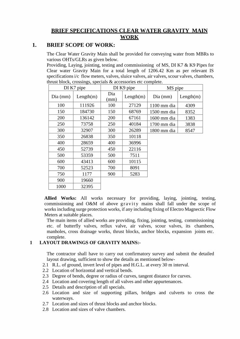
BRIEF SPECIFICATIONS CLEAR WATER GRAVITY MAIN
WORK
1. BRIEF SCOPE OF WORK:
The Clear Water Gravity Main shall be provided for conveying water from MBRs to
various OHTs/GLRs as given below.
Providing, Laying, jointing, testing and commissioning of MS, DI K7 & K9 Pipes for
Clear water Gravity Main for a total length of 1206.42 Km as per relevant IS
specifications i/c flow meters, valves, sluice valves, air valves, scour valves, chambers,
thrust block, crossings, specials & accessories etc complete.
DI K7 pipe DI K9 pipe MS pipe
Dia (mm) Length(m) Dia
(mm) Length(m) Dia (mm) Length(m)
100 111926 100 27129 1100 mm dia 4309
150 184730 150 68769 1500 mm dia 8352
200 136142 200 67161 1600 mm dia 1383
250 73758 250 40184 1700 mm dia 3838
300 32907 300 26289 1800 mm dia 8547
350 26838 350 10118 400 28659 400 36996 450 52739 450 22116 500 53359 500 7511 600 43413 600 10115 700 52523 700 8091 750 1177 900 5283 900 19660 1000 32395
Allied Works: All works necessary for providing, laying, jointing, testing,
commissioning and O&M of above g r a v i t y mains shall fall under the scope of
works including surge protection works, if any including fixing of Electro Magnectic Flow
Meters at suitable places.
The main items of allied works are providing, fixing, jointing, testing, commissioning
etc. of butterfly valves, reflux valve, air valves, scour valves, its chambers,
manholes, cross drainage works, thrust blocks, anchor blocks, expansion joints etc.
complete.
1 LAYOUT DRAWINGS OF GRAVITY MAINS:-
The contractor shall have to carry out confirmatory survey and submit the detailed
layout drawing, sufficient to show the details as mentioned below-
2.1 R.L. of ground, invert level of pipes and H.G.L. at every 30 m interval.
2.2 Location of horizontal and vertical bends.
2.3 Degree of bends, degree or radius of curves, tangent distance for curves.
2.4 Location and covering length of all valves and other appurtenances.
2.5 Details and description of all specials.
2.6 Location and size of supporting pillars, bridges and culverts to cross the
waterways.
2.7 Location and sizes of thrust blocks and anchor blocks.
2.8 Location and sizes of valve chambers.
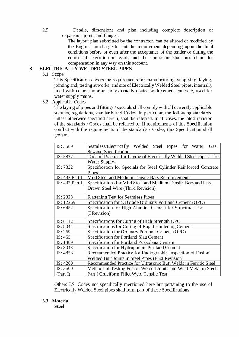
2.9 Details, dimensions and plan including complete description of
expansion joints and flanges.
The layout plan submitted by the contractor, can be altered or modified by
the Engineer-in-charge to suit the requirement depending upon the field
conditions before or even after the acceptance of the tender or during the
course of execution of work and the contractor shall not claim for
compensation in any way on this account.
3 ELECTRICALLY WELDED STEEL PIPES
3.1 Scope
This Specification covers the requirements for manufacturing, supplying, laying,
jointing and, testing at works, and site of Electrically Welded Steel pipes, internally
lined with cement mortar and externally coated with cement concrete, used for
water supply mains.
3.2 Applicable Codes
The laying of pipes and fittings / specials shall comply with all currently applicable
statutes, regulations, standards and Codes. In particular, the following standards,
unless otherwise specified herein, shall be referred. In all cases, the latest revision
of the standards / Codes shall be referred to. If requirements of this Specification
conflict with the requirements of the standards / Codes, this Specification shall
govern.
IS: 3589 Seamless/Electrically Welded Steel Pipes for Water, Gas,
Sewage-Specification IS: 5822 Code of Practice for Laying of Electrically Welded Steel Pipes for
Water Supply- IS: 7322 Specification for Specials for Steel Cylinder Reinforced Concrete
Pipes IS: 432 Part I Mild Steel and Medium Tensile Bars Reinforcement IS: 432 Part II Specifications for Mild Steel and Medium Tensile Bars and Hard
Drawn Steel Wire (Third Revision)
IS: 2328 Flattening Test for Seamless Pipes IS: 12269 Specification for 53 Grade Ordinary Portland Cement (OPC) IS: 6452 Specification for High Alumina Cement for Structural Use
(I Revision)
IS: 8112 Specifications for Curing of High Strength OPC IS: 8041 Specifications for Curing of Rapid Hardening Cement IS: 269 Specification for Ordinary Portland Cement (OPC) IS: 455 Specification for Portland Slag Cement IS: 1489 Specification for Portland Pozzolana Cement IS: 8043 Specification for Hydrophobic Portland Cement IS: 4853 Recommended Practice for Radiographic Inspection of Fusion
Welded Butt Joints in Steel Pipes (First Revision) IS: 4260 Recommended Practice for Ultrasonic Butt Welds in Ferritic Steel IS: 3600
(Part I)
Methods of Testing Fusion Welded Joints and Weld Metal in Steel:
Part I Cruciform Fillet Weld Tensile Test
Others I.S. Codes not specifically mentioned here but pertaining to the use of
Electrically Welded Steel pipes shall form part of these Specifications.
3.3 Material
Steel
The steel used shall be Fe 410 for manufacturing the pipes and specials shall
conform to IS: 2062. The quality of steel, chemical composition and tensile
strength of the steel plates shall be as specified in IS: 3589. The thickness of steel
plates used for manufacturing pipes shall conform to IS: 3589 or as specified. The
thickness of steel plates used shall in no case be less than that specified in IS: 3589.
Cement Mortar and Cement Concrete
The Cement Mortar and Cement Concrete used for pipes and specials shall
conform to the Specifications mentioned in Chapter 9 of Standard Specifications.
The maximum size of aggregate shall be one third the thickness of concrete cover
inside the steel pipe or 10 mm, whichever is less. The concrete mix shall have a
minimum cement content of 450 kg/m3 and a characteristic compressive strength
of 25 N/mm2 at 28 days. The cement mortar shall have a minimum cement content
of 600 kg/m3 and a characteristic compressive strength of 25 N/mm2 at 28 days.
Reinforcement
All cage reinforcement used in the pipes and specials shall conform to IS: 432
(Part- 1) or IS: 432 (Part-2).
Welding Electrodes
All electrodes used for welding of steel plates shall conform to IS: 814.
3.4 Length
The pipes shall be manufactured in lengths of 10-12 m, unless otherwise specified
or agreed to between the MPJNM and the manufacturer, for ease in handling.
3.5 Joints and Ends
Pipe sections shall be of swelled and plain ends suitable for swelled jointing. The
dimensions of sleeves shall be as specified in IS: 3589. Other relevant
Specifications with respect to joints and ends, as per IS: 3589 shall also be
applicable.
3.6 Tolerances
The tolerances over dimensions of pipes for different diameters of pipes shall be as
specified in IS: 3589 and no negative tolerance in pipe thickness shall be accepted.
3.7 Manufacture
Pipes shall be made from steel plates by butt welding spirally. Pipes shall be of
specified nominal diameter after internal lining with 12 mm thick cement mortar
as per Specifications.
Prior to welding, edges of plates shall be prepared suitably. Prior to welding, the
plates shall be fitted closely and during welding they shall be held firmly. Welding
shall be done so that there shall be thorough fusion and complete penetration.
The ends of the steel pipes shall be perfectly vertical to its longitudinal axis.
3.8 Welding
For manufacturing of the steel pipes, any of the following types of welding shall
be adopted as per IS: 3589.
• Automatic submerged arc welding.
• Electric resistance welding.
The welding of pipes in the field and testing should comply with IS: 816.
Plates shall be held in the correct position. Abutting edges shall be properly
squared. Each deposited layer of the welded metal in the fusion welding process
shall be thoroughly cleaned before additional weld metal is supplied to coincide
with the centre line of joint and the finished joint shall be free from all defects.
All welds shall have complete fusion with the base metal and shall be free from
cracks, oxides, slag inclusion and gas pockets.
If welding is stopped for any reason, special care shall be taken when welding is
resumed to obtain complete penetration between weld metal, plate and weld metal
previously deposited. Three percent of all seams of pipes welded in the fabrication
shop shall be Radio graphed (as per IS: 4853) to render visible inspection of any
internal defects such as blow holes, slag inclusion or cracks. If any defects are
detected the metal at the location shall be chipped out and rewelded. In addition to
Radiography of the joints, 100 percent testing by ultrasonic equipment (as per IS:
4260) shall also be included in welding tests. Any defects found out shall be
rectified free of cost. Welds found deficient in quality shall be removed by chipping
or melting and remade as per Specifications. Chipping or cutting the weld shall not
extend to the base metal.
Sample welds shall be submitted for testing. The weld joints shall be tested in
accordance with the procedure laid down in IS: 3600 (Part-I)-1985, as specified in
IS: 5822. Approval of such tests shall be required prior to welding of the pipe.
Manual welding of special sections and fittings will be permitted when it is
impracticable to use an automatic welding machine.
Final welding of closure gaps for buried pipes shall be done after intermediate pipes
have been backfilled.
3.9 Radiograph of welded joints
Soon after welding, each longitudinal / spiral and circumferential welded length,
the minimum length of the weld at random for each pipe shall be radiographed to
detect welding defects, as per the requirements of IS 4853 and as directed by
Engineer. This sampling will be at random to ensure 100% coverage of junctions
of longitudinal / spiral and circumferential joints. If the results of such radiography
fail to conform to the requirements, the Contractor shall carry out at his expense
100 % radiography test for the pertinent pipe as directed and fully satisfying the
Engineer.
The percentage testing of radiography is as follows:
Pipes and Specials manufactured at Mill / Factory - 10%
Field joints welded at site - 5%
The weld ripples or weld surface irregularities and slag etc., on both inside and
outside shall be removed by any suitable mechanical process to a degree such that
resulting radiographic contact due to any remaining irregularities cannot mark or
be confused with that of objectionable defect. The radiograph shall be made in strict
accordance with the latest requirements and as per the latest and most efficient
technique either with X-ray or gamma ray equipment. The safety requirements
during radiography shall be in accordance with IS 2598.
The radiographs are to be marked in such a way that the corresponding portion of
the welded seam and the welder can be readily identified. All radiographs will be
reviewed by the Engineer to identify the defects and determine those which
requires rectification. Defects that are not acceptable shall be removed by chipping,
grinding or flame gouging to sound metal and the resulting cavities shall be welded.
After rectification, the joint is to be radiographed again to prove the quality of the
repair. The radiographs will be judged as acceptable or unacceptable by the
Engineer based on the latest standards prescribed by relevant Indian Standard
specification.
All X-rays shall be taken with equipment and by personnel of the Contractor. Films
shall be developed within 24 hours of exposure and be readily accessible at all
times for inspection by the Engineer. The Contractor shall provide for the use of
the Engineer suitable X-ray viewing equipment. X-ray films shall be properly
maintained by the Contractor. A complete set of radiographs and records as
described in IS: 2595, for each job shall be retained by the Contractor and shall be
handed over to the Engineer on completion of the Contract. All films shall be
identified by the number and chart prepared indicating location of any work
associated with the pipe erection and such inspection shall be performed by the
Radiographer at the discretion of the Engineer.
Radiographic Inspection of welded joints:
All welded joints to be radiographed shall be examined in accordance with -
IS 2595 - Code of Practice for Radiographic Testing
IS 4853 - Recommended Practice for Radiographic Examination of
Fusion Welded Butt – Joints in Steel Pipes
IS 2598 - Safety Code for Industrial Radiographic Practice.
Radiographers performing radiograph shall be qualified in accordance with SNT-
TC- 1A. Supplements and Appendices “Recommended Practice for Non-
destructive Testing Personnel Qualification and Certification” published by the
American Society for Non-destructive Testing as applicable for the technique and
methods will be used.
Final acceptance of radiographs shall be based on the ability to see the prescribed
penetrameter image and the specified hole.
Sections of welds that are shown by radiography to have any of the following types
of imperfections shall be judged unacceptable and shall be repaired.
Any type of crack, or zone of incomplete fusion or penetration, any elongated slag
inclusion which has length greater than 6 mm any group of slag inclusion in line
that have an aggregate length greater than thickness in a length of 12 times
thickness, except when the distance between the successive imperfections exceeds
6 L where L is the length of the longest imperfection in the group, rounded
indications in excess of that specified by the acceptance standards given earlier.
3.10 Fabrication of specials
Specials such as bends, tapers, tees shall conform to IS: 7322. Specials shall be
fabricated by cutting plates of the specified thickness to the required shape obtained
by developing the form of specials on ground. Stiffeners shall be provided
wherever necessary. Abutting profiles shall be obtained using templates which
guide the cutting torches as to obtain a uniform cut. No hand cutting shall be
permitted. Specifications for the using and testing of the plates, electrodes, welding,
cleaning etc., shall be the same as for the straight pipes.
1. Horizontal and vertical curves
Standard bends of deviations from 5 degree to 90 degrees shall be fabricated
out of steel plates. The cut pieces shall as far as possible be placed at the end of
pipes joined in the factory. The angle of the cut pieces shall be made so as to
obtain the necessary curvature. In case of deviations differing from the
standards, cut pieces shall be made to suit the particular site conditions. Length
of the cut pieces shall be in line with standard specials. The vertical cuts shall
be so adjusted as to conform to the proposed longitudinal section. Distance
pieces may be used to obtain the above conditions.
2. Tapers and Tees
Tapers and tees shall be fabricated with one or more stocks, each stock having
a stiffening ring fixed circumferentially in the centre. The stiffener rings shall
be made of M.S. Plate of approved thickness.
3. Provisions for valves
Provisions in the form of stubs of required diameter shall be fabricated by the
Contractor and shall be fixed to the pipeline after cutting pipe with necessary
pad plates.
3.11 Cement Concrete and Mortar Lining of Pipes and specials.
Preparation of surface before lining or coating.
The surface of pipe to be lined or coated with cement mortar or cement concrete
shall be clean. Any loose rust, loose millscale, dirt, debris, oil, grease and other
detrimental materials present shall be removed by mechanical means.
Cement Concrete lining for inside of steel pipes and specials and mortar
coating outside.
Cement Concrete shall be composed of cement, coarse and fine aggregates and
water well mixed and of proper consistency to obtain a dense, homogeneous lining
that will adhere firmly to the pipe surface. Thickness of cement concrete lining
inside the pipe shell shall be of 12 mm and that of the mortar lining outside the pipe
shell shall be 30 mm thick or as per relevant IS specifications.
3.12 Mixing
The concrete for internal lining shall be mixed as per provisions of IS code
3.13 Cover
The clear cover to the reinforcement whether steel cylinder or cage shall not be less
than 9 mm for lining and 12 mm for coating.
3.14 Reinforcement
Wire fabric shall be used for external reinforcement. It shall be 50 x 50 mm steel
wire mesh, 13 gauge each way, and conform to IS: 432 (Part-1) or IS: 432 (Part-
2). The reinforcement cage for the pipes shall extend throughout the pipe barrel
and shall consist of spirals or rings and straights. The spirals or rings shall be
circular in shape and shall be either wound round the steel pipe shell itself or wound
round collapsible frame or drums and then slipped on the steel pipe shell. The fabric
shall be wrapped on the shell by tack welding. The outer cage reinforcement for
swelled end portions of the pipe shall be wound on them at the time of laying.
Minimum reinforcement in the lining shall not be less than three percent of the
quantity of steel pipe shell. Splices shall be made by welding or other suitable
means. The fabric shall be wrapped on the shell by tack welding.
3.15 Equipment for lining of Pipes
1. Straight sections of pipe shall be lined by use of a spinning machine specifically
designed to suit for the purpose of rotating the section and centrifugally
applying cement concrete lining to the interior of steel pipe. Mechanical
feeding is preferable.
2. The Contractor shall plan for installation of sufficient number of spinning
machines/equipment for inside lining and outside coating of pipes, and the
proposed factories. If during the progress of works, it becomes necessary for
transporting of plates/pipes from one factory to the other for fabrication/lining
and or coating due to inadequate number of machines or breakdowns or to meet
progress targets, the Contractor should arrange for such transportation of pipes
from one factory to the other at his own cost.
Concreting lining and mortar coating of pipes
1. This shall be done generally in two stages to give the required thickness of the
barrel.
2. In the first stage concreting shall be done inside the pipe shell and in the second
stage placing of the mortar is done outside the pipe shell. Placing of concrete
inside the steel pipe shell shall always be done at the manufacturer’s works and
consolidated by spinning, vibrating, spinning combined with vibrations or other
appropriate mechanical means whilst the placing of mortar outside the steel
pipe shell shall be done later either at the manufacturer’s works or at site.
3. Mortar coating outside the steel pipe shell shall not commence before the expiry
of three days after the completion of concreting inside, unless otherwise it is
established that the concrete lining inside has attained works cube strength of
not less than 110 kg/cm2, earlier than this period. During this entire period the
concrete inside the steel pipe shell shall be under curing. The mortar outside
the steel pipe shell shall be either vibrated or applied under pressure.
4. In the case of pipes with plain ends or slip-in type ends, the portions that should
be left exposed without concreting or mortar lining shall be mutually agreed to
between the purchaser and the manufacturer.
Lining of specials
1. Whenever practicable, specials shall be made form cut lengths of matured lined
straight pipes. The lining shall be cut back from the end to ends to be bevelled
and welded for a sufficient distance to ensure that any of the concrete lining
which is intended to remain as part of lining shall not suffer damage by the
cutting or welding process. The concrete lining shall be made good by
rendering by hand.
2. Hand rendering of specials shall consist of freshly mixed concrete of a mixture
equivalent to that of the lining being repaired, and shall be thoroughly
compacted and finished to a smooth surface of the correct form.
Cement concrete shall be used both for lining and coating of specials. The
thickness of lining and coating shall be 25 mm. Specials shall have the nominal
dia as that of the connecting pipe after lining. Specifications for lining and
coating of specials shall be as that of the straight pipes.
3. The application of cement concrete lining to bends, or specials sections whose
shapes preclude other process of lining shall be by mechanical placement,
pneumatic placement or hand troweling finished to produce a smooth dense
surface. Debris shall be removed as necessary, permitting the application of the
lining to a clear surface.
4. Thickness shall be as required for spun lining of straight sections except that it
may be varied by feathering or filleting to affect system lining with adjoining
sections of pipe and thickness of lining.
Determination of thickness of lining
Lining thickness shall be determined on the freshly lined pipes, at intervals frequent
enough to assure compliance. Thickness of lining may be determined by means of
a steel pin not larger than 1.5 mm in diameter or on a hardened concrete or mortar
by means of a non-destructive measurement process. The lining shall be measured
at four equidistant points on two cross sections of the barrel at each end of the pipe
or fittings. The first set shall be at least 200 mm from the respective ends of the
pipe or fitting. The second set shall be made as far into the interior of the pipe or
fitting as can be readily reached without injuring the lining.
Curing
1. After completion of concreting or mortar lining, the concrete or mortar shall be
kept wet by any suitable means such as immersion in water, covering by wet
gunny bags, or by mechanical sprinklers, for a period of not less than 14 days
when cement conforming to IS: 269 or IS: 455 or IS: 1489 or IS: 8043 or IS:
6909 is used; not less than 7 days when cement conforming to IS: 8041 or IS:
8112 is used; not less than 3 days when cement conforming to IS: 6452 or IS:
12269 is used; and not less than 21 days when cement conforming to IS: 12330
is used.
2. Non-pressure steam curing may be permitted provided the requirements of non-
pressure steam curing are fulfilled. For non-pressure steam curing, the pipe
shall be subjected to the action of thoroughly saturated steam at a temperature
of 38 to 54 degree C for a period of not less than 24 hours or for such additional
time as may be necessary to enable the pipe to meet the strength requirements.
Repair of defective or Damaged Areas of lining
Defective or damaged areas of linings may be patched by cutting out the defective
or damaged lining to the metal so that the edges of lining not removed are
perpendicular or slightly undercut. A fresh mix of concrete or mortar equivalent to
that of the lining being repaired shall be prepared. The cut-out area and the
adjoining lining shall be thoroughly wetted, and the concrete or mortar applied to
the inside or outside respectively and trowelled smooth with the adjoining lining.
After any surface water has evaporated, but while the patch is still moist, it shall be
cured as specified.
Protection of work
The lined pipe and fittings shall be protected from extreme heat due to direct sun
rays, from impact of rainfall, and from freezing temperatures until the linings have
cured sufficiently to withstand these conditions.
3.16 Workmanship
All pipes shall be cleanly finished free of cracks, surface flaws, laminations and all
other defects. They shall be cylindrical, concentric and straight in axis. The ends
shall be accurately cut and shaped for welds. The ends shall be square with the axis
of the pipe. The repair of minor defects by welding or otherwise shall be permitted
only after obtaining the prior permission from the Engineer in writing. No heating
shall be permitted.
3.17 Handling of pipes and specials.
During manufacturing and during the entire period of the application of concrete
or mortar lining protection and the curing thereof, the section shall be carefully
supported and handled so as to avoid injury to the fresh lining. If a pipe section
must be rolled or otherwise moved, such operation shall be done slowly and with
every reasonable precaution against damage. Any portion of the lining, coating that
may become damaged shall be cut and replaced.
During delivery, all sections shall be handled by such means and in such a manner
that no distortion or damage is done to the protection or to the section as a whole.
3.18 Laying of pipes
Pipes shall be laid in accordance with standard laying procedures.

All pipes shall be laid true to line and level and on pedestals wherever required, the
joints strictly conforming to welding Specifications. Joints shall be finished in a
workman like manner and shall prove to be sound and water tight. The field
welding shall be carefully carried out so as to induce the minimum heat distortion
and local hardness in steel.
In addition, the provisions of IS: 5822 shall also be applicable.
3.19 Field Jointing of Insides and outsides of Concrete lined pipes.
Cement mortar shall be used for lining of inside and outside lining of joints. It shall
be of the same Specifications as those of outside mortar coating of pipes, cement
mortar lining for inside and outside of field joints shall be done only after testing
the pipe line as per Clause 15.5.17.3.
Jointing Inside
For the inside lining of field joints, wire fabric of 50 x 50 mm steel mesh, 13 gauge
each way, shall be provided. Inside joints of mortar lined pipe shall be plastered with
cement mortar and finished off smooth with the inside surface of the pipe by
trowelling or by other equipment means. Before placing the joint mortar material
against the surface of the lining, these surfaces shall be carefully cleaned and wetted
to ensure good bond between the lining and joint mortar. The field joint shall be
cured for a minimum of 14 days. In any case the pipe line shall not be put into serve
until the mortar has cured for a minimum of 24 days. The joints shall be finished off
smooth with the inside surface of the lining by trowelling.
Jointing Outside
1. For this item, the joints have been classified into two groups:
• Those coming under water logged area
• Those coming in other area.
2. Joints under waterlogged areas: These joints shall be done with Cement Mortar
1:2 with two layers of M.S. 50 mm x 50 mm x 13 gauge weld mesh and the
thickness of mortar shall be 50 mm thick and a suitable water proofing
compound shall also be used.
3. Joints coming in other areas: This shall be done with Cement mortar 1:2, 25
mm thick with one layer of 50 mm x 50 mm x 13 gauge wire fabric
reinforcement.
4. Outside field joints shall be coated with cement mortar retained by suitable
forms so as to bridge the joints. The mortar shall be compacted within the form
to produce a dense coating without voids. The joint coating shall be kept moist
for a minimum or 14 days.
3.20 Fixing of fixtures
Contractor has to fix the required number of fixtures at proper locations as per the
approved Drawings and the instructions of Engineer. The fixtures shall be fixed to
the flanges by bolts, nuts and washers with necessary fireplay insertions etc. All
types of fixtures and necessary equipment required for fixing these fixtures shall
be arranged by the Contractor at his own cost.
3.21 Testing of Pipe line
Mechanical Test (Tensile Test)
Tensile test shall be carried out as specified in IS: 1894:1972. The tensile strength
and percentage elongation of pipes shall not be less than the values specified in the
table below. The percentage elongation shall be determined on a gauge length of
5.65 times of square root of original cross sectional area of the specimen (So).
Steel grade Tensile strength MPa (min) Percentage elongation (min) Fe 330 330 20 Fe 410 410 18 Fe 450 450 12
Hydrostatic Testing at Works
1. Each straight pipe section whose ends are in plane at right angle to the pipe
axis shall be tested hydrostatically before the pipe is coated, wrapped or lined,
as per IS: 3589. The pipes shall withstand the test pressure without showing
any signs of weakness, leak or sweating. The test shall be carried out in the
presence of the Engineer and as per Specifications. The required pressure
should be maintained for at least 2 minutes for inspection purposes. The pipes
shall be fitted with an accurate pressure gauge approved by the Engineer.
2. The hydraulic test pressure shall be the pressure calculated from the formula
P=2St/D except that the maximum test pressure shall not exceed 5 MPa.
Where
P = Test pressure in MPa
S = Stress in MPa which shall be taken as 40 % of specified minimum
tensile strength
t = Specified thickness in mm
D = Specified outside diameter in mm
3. In this test, no hammering shall be permitted. Any section showing more than
one leak for each 1.5 metres of welded seam or more than 2.5 percent of the
total lengths of welded seam will be rejected. Stopping leaks by means of
caulking tools shall not be permitted. In sections showing less than one leak for
each 1.5 meters of welded seam and not more than 2.5 percent of the total
lengths of welded seam, the leaks shall be repaired by chipping the weld and
rewelding, after obtaining the permission of the Engineer in writing. All such
sections shall be clearly indicated in the logbook for reference. The repaired
pipe should be retested hydrostatically for specified pressures. If on retest a
pipe shows any leak in the welded seams it will be rejected. Accepted pipe
sections shall be marked with legible marks of identification. This test is
compulsory on all straight pipes.
Testing at site
1. After completing the installation of pipe line, or a section of the line and
welding of joints, a hydrostatic pressure test of the line shall be made before
giving the lining and coating to the exposed joints. The hydrostatic pressure
shall be maintained as per Clause 11.2.1 of IS: 5822:1994, during which time
the pipe shall not show any sign of sweating or oozing or spotting of water at
the joints or any part. If a drop in pressure occurs the quality of water added in
order to re- establish the test pressure, should be carefully measured. This
should not exceed 0.1 litre per mm of pipe diameter per km of pipe line per day
for each 30 m head of pressure applied.
2. If the pressure measurements are not made at the lowest section, an allowance
should be made for the static head between the lowest point and the point of
measurement to ensure that the maximum pressure is not exceeded at the lowest
point. Any defective joint or part shall be repaired and retested in the presence
of the Engineer. The Contractor shall make his own arrangements for water for
field testing. Water if supplied by department will be charged at non- domestic
rates prevalent at the time of supply. The pipe line shall be tested in stretches
of not exceeding 2 km in length. This field hydraulic test is mandatory. This
clause is not negotiable.
3.22 Measurements
The net length of pipes of specified thickness as laid or fixed shall be measured
nearest to cm and weight shall be worked out . The portion of the pipe at the joints
shall not be included in the length of pipe work. Excavation, refilling, shoring and
timbering in trenches masonry or concrete pillars and thrust blocks wherever
required is inclusive.
4.0 Supply and laying, jointing of Ductile Iron pipes and Specials
4.1. Standards
Except as otherwise specified, the Indian/International Standards and Codes of
Practice in their latest version shall be adhered to for the design, manufacturing,
inspection, factory testing, packing, handling and transportation of product. Should
any product be offered conforming to other standards, the equipment or products
shall be equal to or superior to those specified and the documentary confirmation
shall be submitted for the prior approval of the Engineer in Charge. DI pipes of ISO
standard shall also be accepted.
IS: 8329 Centrifugally cast (spun) ductile iron pressure pipes for water,
gas and sewage
IS: 5382 Rubber sealing rings for gas mains, water mains and sewers
IS: 638 Sheet rubber jointing and rubber insertion jointing
IS: 9523 Specification for DI fittings for pressure pipes for water, gas, and
sewage
BS: 4772 Specification for DI fittings
IS: 11606 Methods of sampling of cast iron pipes and fittings
IS: 1608 Mechanical testing of metals – tensile testing
IS: 12288 Code of practice for use and laying of ductile iron pipes
4.2 Specifications for Ductile Iron Pipes:
4.2.1 Casting
The pipes will be centrifugally cast (spun) Ductile Iron pipes for Water, confirming
to the IS 8329. The pipes used will be with push on joints (Rubber Gasket Joints).
The class of pipe to be used shall be of the class K-7 and K9.
4.2.2 Surface coating
The pipes shall be coated with Metallic Zink coating as per appendix A, with
a finishing layer of bituminous paint, and have factory provided cement mortar
lining in the inside as per the provisions of Appendix B of the IS 8329.
4.2.3 Standard length
The pipes will be supplied in standard lengths of 5.50 and 6.00 meters with
chamfered ends suitable for push-on jointing. Each pipe of the push on joint variety
will also be supplied with a rubber EPDM gasket, confirming to the IS: 5382. Any
change in the stipulated lengths will be approved by the Engineer – in charge.
4.2.4 Manufacture of Gaskets
The gaskets should also be supplied by the manufacturer of the pipes. They should
preferably be manufactured by the manufacturer of the pipes. In case they are not,
it will be the responsibility of the contractor to see that the manufacturer of the
pipes get them manufactured from a suitable manufacturer under its own
supervision and have it tested at his/sub contractor’s premises as per the contract.
The pipe manufacturer will however be responsible for the compatibility and
quality of the products.
4.2.5 Flanged joints
The flanged joints will confirm to the Clause 6.2 of IS 8329. The pipe supply will
also include one rubber gaskets for each flange.
4.2.6 Hydraulic test at works
Each and every pipe shall be tested hydraulically by the manufacturer as specified
under clause 11 for the pressures specified in table 1 of IS: 8329. The test shall
be carried out before application of surface coating and lining except Zinc
coating which may be applied before the hydrostatic test.
4.2.7 Test for Gaskets
The test reports for the rubber gaskets shall be as per acceptance tests of the IS 5832
and will be in accordance to Clause 3.8 and contractor shall submit the test
certificate issued by the manufacturer with the pipe supply, without which payment
for pipe supply shall not be released.
4.2.8 Third party inspection
The inspection and testing of the pipes shall be carried out by the employer and/
or inspecting agency appointed by the employer, in the manufacture’s workshop.
The pipes will be subjected to following tests for acceptance:
4.2.8.1 Visual and dimensional check as per Clause 13 and 15 of IS 8329 for
length, internal and external diameter, wall thickness, deviation from
straight length and ovality.
4.2.8.2 Mechanical Tests as per Clause 10 of IS 8329 for tensile strength and
Brinell hardness test.
4.2.8.3 Hydrostatic Test as per Clause 11 of IS: 8329.
The sampling for the above tests shall be as per the provisions under clause 9 of the
IS:8329. All the tests shall be conducted in presence of the inspecting agency. The
pipes shall be dispatched only after issue of the test certificate by the inspecting
agency for satisfactory test results as required. The inspection charges for such tests
shall be paid by the contractor to the inspecting agency.
4.2.9 Retest
If a test piece representing a batch fails in the tensile or Brinell hardness test in the
first instance, two additional tests shall be made on test pieces selected from two
other pipes from the same batch. If both the test results satisfy the specified
requirements, the batch shall be accepted. Should either of these additional test
pieces fail in the test, the batch shall be deemed as not complying the required
standards and shall be rejected.
4.2.10 Marking
4.2.10.1 All pipes will be marked as per Clause 18 of IS 8329 and show as below:
4.2.10.2 Manufacturer name/ stamp
4.2.10.3 Nominal diameter
4.2.10.4 Class reference
4.2.10.5 A white ring line showing length of insertion at spigot end
4.2.11 Packing and Transport:
The pipes should be preferably transported by road from the factory and stored as
per the manufacturer specifications to protect damage.
4.3 Specifications for Ductile Iron Fittings (Specials)General
The Ductile Iron (DI) fittings shall be D.I. fittings shall be ISI marked as per IS
: 9523-2000, suitable for Tyton joints to be used with Ductile Iron pipes with
flanged and Tyton jointing system.
4.3.3 Types of specials
The following types of DI fittings shall be manufactured and tested in accordance
with IS: 9523 or BS: 4772
4.3.3.1 flanged socket
4.3.3.2 flanged spigot
• double socket bends (900, 45
0, 22½
0, 11¼
0)
4.3.3.3 double socket branch flanged tee
4.3.3.4 all socket tee
4.3.3.5 double socket taper
4.3.3.6 All the fittings shall be of PN 16 pressure rating
4.3.4 Supply
All the DI fittings shall be supplied with one rubber ring for each socket. The rubber
ring (EPDM) shall conform to IS: 12820 and IS: 5382. Flanged fittings shall be
supplied with one rubber gasket per flange and the required number of nuts and
bolts.
4.3.5 Manufacture of Fittings / Specials
The metal used for manufacture of DI Fittings / Specials shall conform to the
appropriate grade as specified in IS : 1865-2005.
Two side lugs shall be provided on each Socketed fitting, across all types and sizes
along with Lifting loops on fitting across all types and sizes from DN 400 & above.
D.I. Fittings shall also contain a Stub, minimum length -15mm x dia.- 10 mm.,
which can be cut at random to carry out Metallographic test to ascertain minimum
80% Graphite Nodularity as per Clause – 9.1 of IS : 1865-2005, in the form - V or
VI as per IS : 7754-2003. Fittings manufactured through Induction furnace route
only shall be used.
The fittings should also be supplied by the manufacturer of the pipes. They should
preferably be manufactured by the manufacturer of the pipes. In case they are not,
it will be the responsibility of the contractor to see that the manufacturer of the
pipes get them manufactured from a suitable manufacturer under its own
supervision and have it tested at his/sub-contractors premises as per the contract.
The pipe manufacturer will however be responsible for the compatibility and
quality of the products.
4.4 Lubricant for ductile iron pipes and specials
4.4.2 General
This section covers the requirements for lubricant for the assembly of Ductile Iron
pipes and specials suitable for Tyton push-in rubber ring joint.
4.4.3 Specification
The lubricant has to have the following characteristics:
4.4.3.1 must have a paste like consistency and be ready for use
4.4.3.2 has to adhere to wet and dry surfaces of DI pipes and rubber rings
4.4.3.3 to be applied in hot and cold weather; ambient temperature 0 -
50°C, temperature of exposed pipes up to 70°C
4.4.3.4 must be non-toxic
4.4.3.5 must be water soluble
4.4.3.6 must not affect the properties of the drinking water carried in the pipes
4.4.3.7 must not have an objectionable odor
4.4.3.8 has to inhibit bacterial growth
4.4.3.9 must not be harmful to the skin
4.4.3.10 must have a shelf live not less than 2 years
4.4.4 Acceptance tests
They shall be conducted in line with the provisions of the IS 9523.
4.4.5 Packing for DI specials and Rubber Gaskets
All the DI fittings shall be properly packed with jute cloth. Rubber rings shall be
packed in polyethylene bags. Rubber rings in PE bags and nuts, bolts etc. shall be
supplied in separate jute bags.
4.5 Laying and jointing of DI pipes and specials
4.5.2 Use of tackle
Pipes should be lowered into the trench with tackle suitable for the weight of pipes.
For smaller sizes, up to 200 mm nominal bore, the pipe may be lowered by the use
of ropes but for heavier pipes suitable mechanical equipment have to be used.
4.5.3 Cleaning
All construction debris should be cleared from the inside of the pipe either before or
just after a joint is made. This is done by passing a pull-through in the pipe, or
by hand, depending on the size of the pipe. All persons should vacate any section
of trench into which the pipe is being lowered
4.5.4 Laying on steep slopes
On gradients of 1:15 or steeper, precautions should be taken to ensure that the spigot
of the pipe being laid does not move into or out of the socket of the laid pipe during
the jointing operations. As soon as the joint assembly has been completed, the pipe
should be held firmly in position while the trench is back filled over the barrel of the
pipe.
The designed anchorage shall be provided to resist the thrusts developed by internal
pressure at bends, tees, etc.
The assembly of the pipes shall be made as recommended by the pipe manufacturer
and using the suitable tools.
4.5.5 Jointing
The socket and spigot ends of the pipes shall be brushed and cleaned. The
chamfered surface and the end of the spigot shall have to be coated with a suitable
lubricant recommended by the manufacturer of the pipes. Oil, petroleum bound oils,
grease or other material which may damage the rubber gasket shall not be used
as lubricant. The rubber gasket shall be inserted into the cleaned groove of the
socket. It has to be checked for correct positioning.
The two pipes shall be aligned properly in the pipe trench and the spigot end shall
be pushed axially into the socket either manually or with a suitable tool specially
designed for the assembly of pipes and as recommended by the manufacturer. The
spigot has to be inserted up to the insertion mark on the pipe spigot. After insertion,
the correct position of the socket has to be tested with a feeler blade
4.5.6Deflection of the pipes Deflection of the pipes -if any- shall be made only after
they have fully been assembled. The deflection shall not exceed 75 % of the values
indicated by the pipe manufacturer.
4.5.7 Anchoring of the pipeline
Thrust blocks shall be provided at each bend, tee, taper, end piece to prevent undue
movements of the pipeline under pressure. They shall be constructed as per design
approved by the Engineer according to the highest pressure during operation or
testing of the pipes, the safe bearing pressure of the surrounding soil and the friction
coefficient of the soil. This item shall be payable as per the provision under BOQ.
4.5.8 Measurement and payment
The net length of pipes as laid or fixed shall be measured in running meters correct
to a cm. Specials shall be included and measured in the total length. The portion of
the pipe at the joints (inside the joints) shall not be included in the length of pipe
work.
5 Excavation and preparation of trenches for laying underground pipeline
5.1 The trench shall be so dug that the pipe may be laid to the required alignment and at
required depth. For road cutting and restoration of concrete/ BT roads, estimates are
based on conventional method. However, as directed by the Engineer in Charge, the
contactor is required to complete this work either (i) with concrete cutter/ trenching
machine, or (ii) using trenchless technology. When the pipeline is under a roadway, a
minimum cover of 1.2 m under major roads shall be provided, in other cases the
minimum cover of 0.9 m above the crown of the pipe shall be provided, if due to the any
condition the pipe are not laid at prescribed depth, deduction will be made as per UADD
ISSR May 2012. The trench shall be shored, wherever necessary and kept dry so that the
workman may work therein safely and efficiently. Under roadway and places where it is
not possible to lay pipes up to required depth or laid open on ground shall be encased all
round with the 1:1.5:3 ( M15) cement concrete.
5.2 Recovery of other serviceable material:-
All serviceable materials such as wood work, bricks, masonry etc. recovered during
the operation of cleaning or excavations, which, in the opinion of the Engineer-
in- Charge are suitable for reuse in restoring the surface, shall be separately stacked
and disposed-of as directed by Engineer-in-Charge.
5.3 Dewatering:-
Dewatering shall be carried out by the contractor, wherever necessary. The discharge
of the trench dewatering pumps shall be conveyed either to drainage channels or to
natural drains and shall not be allowed to spread over in the vicinity of work place.
Trenching:-
The trench shall be so dug that the pipe may be laid to the required alignment and at
required depth. For road cutting and restoration of concrete/ BT roads, estimates are
based on conventional method. However, as directed by the Engineer in Charge, the
contactor is required to complete this work either (i) with concrete cutter/ trenching
machine, or (ii) using trenchless technology. When the pipeline is under a roadway, a
minimum cover of 1.2 m shall be provided, in other cases the minimum cover of 1 m
above the crown of the pipe shall be provided. The trench shall be shored, wherever
necessary and kept dry so that the workman may work therein safely and efficiently.
Under roadway and places where it is not possible to lay pipes upto required depth or
laid open on ground should be encased all round with the 1:2:4 ( M15) cement
concrete.
5.4 Preparation of bottom of trench:-
The bottom of the trench shall be properly trimmed to permit even bedding of the
pipeline. The curvature of the bottom of the trench should match the curvature of the
pipe as far as possible, subtending an angle of 120o
at the centre of the pipe. Where
rock or boulders are encountered, the trench shall be trimmed to a depth of at least
100 mm below the level at which the bottom of the pipe is to be laid and filled to
a like depth with non- compressible material like sand or crusher dust or moorum
of adequate depth to give the curved seating.
5.5 Special foundation in poor soil:-
Where the bottom of the trench at subgrade is found to consist of material, which
is unstable to such a degree that in the opinion of Engineer-in-Charge it cannot be
removed and replaced with an approved material thoroughly compacted in place to
support the pipe properly, a suitable foundation for the pipe, consisting of piling,
timbers or other materials, in accordance with the direction of the Engineer-in-Charge,
shall be constructed.
5.6 Excavation in hard rock by blasting:-
Blasting for excavation shall be done only when the contractor obtains the license for
the same and only when proper precautions are taken for the protection of persons and
property. The hours of blasting shall be fixed by the Engineer-in-Charge. The
procedure of blasting shall conform to the requirement of licensing authority. The
excess excavation by blasting shall be filled up by 1:4:8 cement concrete. The
contractor shall have to make his own arrangement for procurement and storing of
explosives required for blasting.
Rubble available from excavation of hard rock, shall be the property of the contractor,
for which recovery of INR 65/- per cum of the quantity of hard rock excavated shall be
made from his running account bills.
5.7 Braced and sheeted trenches:-
Open-cut trenches shall be sheeted and braced as required by Engineer-in-Charge and
as may be necessary to protect life and property or the work. When closed sheeting is
required, it shall be so driven as to prevent adjacent soil from entering the trench either
below or through such sheeting.
5.8 Stacking of excavated material:-
All excavated materials shall be stacked in such a manner that it does not endanger the
work and avoids obstructing footpaths and roads, hydrants under pressure, surface
boxes, fire, or other utility controls shall be left unobstructed and accessible until the
work is completed. Gutters shall be kept clear or other satisfactory provisions made for
street drainage and natural watercourses shall not be obstructed.
5.9 Barricades, guards and safety provisions:-
To protect persons from injury and to avoid damage to property, adequate barricades,
construction signs, torches, red lanterns and guards, as required, shall be placed and
maintained during the progress of the construction work and until it is safe for traffic to
use the roadway. All materials, piles, equipments and pipes, which may obstruct traffic,
shall be enclosed by fences or barricades and shall be protected by proper lights when
visibility is poor. The rules and regulations of the local authorities regarding safety
provisions shall be observed.
5.10 Maintenance of traffic and closing of streets:-
The work shall be carried out in such manner that it causes the least interruption to
traffic, and the road/street may be closed in such a manner that it causes the least
interruption to the traffic. Where it is necessary for traffic to cross open trenches,
suitable bridges shall be provided. Suitable signs indicating that a streets is closed shall
be placed and necessary detour signs for the proper maintenance of traffic shall be
provided.
5.11 Structure Protection:-
Temporary support, adequate protection and maintenance of all underground and
surface structures, drains, sewers and other obstruction encountered in the progress of
the work shall be furnished under the direction of the Engineer-in-Charge. The
structures, which may have been disturbed, shall be restored upon completion of the
work.
5.12 Protection of property and surface structures:-
Trees, shrubbery fences, poles and all other property and surface structure shall be
protected unless their removal is shown on the drawings or authorized by the Engineer-
in-Charge. When it is necessary to cut roots and tree branches such cutting shall be
done under the supervision and direction of the Engineer-in-Charge.
5.13 Avoidance of the Existing Service:-
As far as possible, the pipeline shall be laid below existing services, such as water and
gas pipes, cables, cable ducts and drains but not below sewers, which are usually laid at
great depth. If it is unavoidable, pipeline should be suitably protected. A minimum
clearance of 150 mm shall be provided between the pipeline and such other services.
Where thrust or auger boring is used for laying pipeline across road, railways or other
utilities, larger clearance as required by the concerned authority shall be provided.
Adequate arrangements shall be made to protect and support the other services during
laying operations. The pipeline shall be so laid as not to obstruct access to the other
services for inspection, repair and replacement. When such utilities are met with during
excavation the authority concerned shall be intimated and arrangements made to support
the utilities in consultation with them.
5.14 Restoration of sewerage system: If the sewer lines are coming in the way of pipeline
alignment, it shall be properly restored either by constructing manholes on both sides
and connecting it with similar sewer line, so as not to disrupt the services of the
sewerage system or by laying the pipeline below or above the sewerage system as per
the directions of Engineer-in-Charge.
5.15 Preparation of Formation for Sections of pipe line to be laid above Ground:-
Formation should be prepared by cutting high grounds and filling in low areas. Care has
to be taken while fixing the alignment and gradient of the pipeline, to balance the
cutting and filling quantities, as far as possible, with minimum of lead. Care should also
be taken to ensure that pipe rests fully either on cutting or on bank.
5.16 Disposal of surplus material:
Excavated material in excess than required for backfilling the trenches, shall be
disposed off as per the directions of Engineer-in-Charge. Surplus excavated stuff
available at one section shall be used for back filling at other reaches, wherever required.
5.17 Extra material required for back filling:
If in any case, it is required to bring the soil for back filling from outside, it should be
of good quality and should not have chemicals e.g. sulphates, chlorides & conductivity
etc., which may cause corrosion to pipes, specials and other structures, beyond the
permissible limits.
5.18 Road, rail and river crossings: -
The mode of laying the pipeline, crossing road, railway or river in the entire project
shall be determined so as to satisfy the requirement of the authority concerned. Cost of
all such crossings shall be included in the rates and no extra payment shall be made on
that account. Laisoning with the concerned authorities will be under the scope of the
contractor, only the fee/charges, if any payable to the concerned department/authority for
grant of permission will be paid/reimbursed by MPJNM.
CHAPTER – 1.5
BREIF SPECIFICATIONS FOR WATER TREATMENT PLANT
HAVING CAPACITY TO PROVIDE 166 MILLION LITRES
OF TREATED WATER IN 23 HOURS
All units and components of Water Treatment Plant shall be designed as per
recommendations of Manual on Water Supply and Treatment, published by
CPHEEO, Ministry of Urban Development, Govt. of India.
A- SCOPE OF WORK:
The Contract on turnkey basis comprises all necessary site investigations,
functional planning, supply of Plant, general design, detailed design, manufacture,
supply, delivery to site, installation, construction, testing and commissioning of
all works required for the Water Treatment Plant of capacity to provide 166
million liters of treated water in 23 hours including all associated mechanical and
electrical plants, equipment's and services, civil and building works, pipe lines and
appurtenances from the raw water inlet up to clear water reservoir and pump house.
The principal requirement is a spacious and convenient layout. The structure
should represent a pleasing appearance with aesthetic features forming a balance
between function and form. Architectural style representing the area/state should
be given to the structure.The interiors of the structure shall be eye appealing and in
keeping with the objectives of the plant viz., production of potable and wholesome
water.
While designing and constructing, it should be ensured that all materials, design,
construction and fabrication details for different units including doors and
windows conform to the IS-specifications and codes of practice wherever available
and in their absence, to the established standards.
1. The scope of work includes but shall not be limited to the provision of the following
:-
1.1 Study of available data with department and if required collection of additional
field data's and site investigations.
1.2 Planning and design of most economical type of treatment plant to generate
166 Million liter filtered water in 23 hours, with due consideration of future
expansion (Requirement for the year 2047).
1.3.1 The detailed design including hydraulic and structural design, development and
preparation of detailed plant working drawings, diagrams and cable schedules
and detailed structural steel fabrication drawings, preparation of design reports,
manufacture and testing at places of manufacture, transport, delivery, erection,
building-in, setting to work, commissioning, testing of all plant required for the
Water Treatment Works,
1.3.2 The contract is including but not limited to pipelines, pumping installations, blowers,
compressors, machinery, apparatus, station pipe work, lifting, handling
,ventilation equipments, electrical equipments, instrumentation, control, compatible
PLC, interfacing lighting systems, earthing, fire safety and lightning protection
systems, materials, articles, fittings and accessories, ancillary works of all kind and
nature required for installations of the highest possible operative standards and for
compliance with the standards prescribed in the Specification and with the
particulars and guarantees entered by the Contractor in the schedules.
1.4 Design & Construction of Cascade Aerator or any other suitable system, for removal
of iron in incoming Raw water if required.
1.5 Design & Construction of sedimentation tank if required.
1.6 Supply and erection of Dosing equipments of coagulants, including chemicals
with facilities to store Alum and chemicals for 3 months.
1.7 Design and construction of Flash mixers.
1.8 Design & Construction of Distribution chamber for clarifiers / flocculators.
1.9 Design & Construction of Clarifiers and flocculators.
1.10 Design & Construction of Rapid gravity sand filters, filter galleries, wash water
tank, filter back wash system and filter control block.
1.11 Design and construction of clear water sump to store treated water.
1.12 Design and construction of clear water Pump House to accommodate the clear water
pumps, electrical panels, control room etc.
1.13 Design & Construction of chlorination plant building, facilities for post and/or
pre chlorination and storage of chlorine cylinders for 90 days requirement.
1.14 The sludge, from plain sedimentation tank, clarifier and flocculators is to be
collected in sludge receiving tanks by gravity and disposed into sludge drying
beds with drainage facilities to reuse at flax mixer/ inlet channel. The back wash
water from filter is to be collected into settling tanks by gravity and to be recycled
after settlement by pumping, raw water inlet channel. The overflow from various
units shall be connected to the storm water drains for safe disposal to the
nearly water bodies with environmental acceptance.
1.15 Monitoring and instrumentation with their housing.
1.16 Electrical works including incoming cable from substation to main control
panel, motor control centers, local control and panels compatible PLC,
interfacing, power and control cabling, plant ventilation and lighting etc.
1.17 Pipe lines, valve chambers, service water installation, sampling and water
quality monitoring, instrumentation and other miscellaneous works associated with
the plant.
1.18 Levelling the treatment plant site and landscaping.
1.19 Storm water drain and sewers with appurtenances.
1.20 Administrative building, laboratory, store, and for control arrangements housing
building, i/c services such as electrical, Lighting, water supply, sanitation and
air conditioning facilities.(The air conditioning facilities shall be provided only for
control room having instrumentation.)
1.21 Guard Room - with not less than 6.0 sqmt floor area with toilet facilities and
Building services.
1.22 A Conference room – of size 6 X 12 m with sitting capacity of 30 persons with
toilet facilities and Building services.
1.23 Internal roads with storm water drains, landscaping and area lighting etc.
1.24 Training of PHE / Jal Nigam personnel in operation and maintenance of the plant
during the last three months of O&M period.
1.25 BY PASS CHANNEL
(i) Raw water channel to flocculaters by passing primary sedimentation tank.
(ii) Raw water channel to filters by passing flocculation and sedimentation unit.
The channels shall be designed as a one unit provided with sluice gates
arrangement for isolation of channels. These channels shall be designed for
capacity with 20% over load.
1.26 Cascade Aerator - shall be designed in circular shape with circular Gullet to
collect water.
1.27 Primary Sedimentation Tank. - Designed for the distension time as per the
provisions in CPHHEO Manual, it shall have properly designed inlet and out let
arrangement with due consideration to the better efficiency of settling, mechanical
sludge cleaning arrangement with sludge effluent pipe etc. complete.
1.28 CLARIFLOCULATORS : Designed with properly designed inlet and outlet
arrangement with due consideration to the better efficiency of settling, mechanical
sludge cleaning arrangement with sludge effluent pipe etc. complete.
Clariflocculator shall be designed for 25% overloading including inlet and outlet.
1.29 FILTRATION:
Designed rapid gravity sand filters in even numbers.
1.30 WALK WAY AND PIPE GALLERY:
The minimum walk way near the filter should be 1.5 mt. wide and pipe
gallery should be minimum 2.00 mt. or more wide to accommodate all the pipes and
valves and have a proper slope to drain out the wash water through wash water pipe.
1.31 MODULE CHAMBER ROOM OR CLEAR WATER CONTROL
CHAMBER ROOM:
It shall be designed to accommodate module chambers of all filters including
weir, wash water tank pump and air blowers. The height should be sufficient so
that the wash water tank may be constructed above it.
1.32 CHLORINE HOUSE AND CHLORINE CYLINDER STORE ROOM:
It should have sufficient space to accommodate liquid or gaseous feed
chlorinator with weighing machine of 2 ton capacity. The cylinder storing room
should have the sufficient capacity to accommodate cylinder/toner for at least
90 days storage. It should be forced ventilated, easily accessible from at least
two sides. It should have arrangement near the ramp to unload the truck by
providing chain pulley arrangement at a height of minimum 5.00 mt.
1.33 STORAGE TANK FOR NEUTRALIZATION OF CHLORINE:
Solution storage tank of minimum dimension 3.00x3.00x2.00 mt. size should
be provided with fire resisting tiles cladding. It should be easily accessible from
chlorine house or storage room.
1.34 CLEAR WATER STORAGE TANK/SUMP :
1.35 Designed for 2 hours detention period capacity and this capacity will be divided in 2
compartments capable for isolation provided with scouring arrangement overflow
arrangement, manholes, air ventilation cowels, ladders etc.
CLEAR WATER PUMP HOUSE :
It should have sufficient space to accommodate required number of pump and
arrangement to pump treated / clear water to the required places.
Pumping arrangement will, at least, have minimum numbers of centrifugal pumps as
specified including cable ducts, surge protection (If so required), NRV, suction pipe
etc. complete. It should have sufficient height to accommodate the gantry crane of
suitable capacity. It should have additional store room of minimum size
5.00x4.00x4mt. Switch Board room of minimum size 3.00x6.00mt and office room
minimum 4.00x6.00mt. in size and toilet units.
1.36 LABORATORY BLOCK :
There should be one laboratory block of 60 sqm minimum area or as per
recommendation of CPHEEO Manual on Water Supply and Treatment, whichever
is more; provided with one Chemist room, one office room and remaining part
for storing t h e chemicals and conduct ing the test, toilet. WC block should
be attached with laboratory.
1.33 WASTE WATER COLLECTING SUMP AND WASTE WATER LINE :
The waste water or sludge water from flocculator, clarifier and filter plant and
other units shall be collected in waste water collecting tank of at least suitable
detention time and depth according to the levels. It shall have such level that the
waste clear water tank can be cleaned easily. The overflow of waste water from
tank will be directly discharged by gravity away from treatment plant to the
natural Drain. The chambers shall be provided at maximum 60.00 mt. Internal
and at turning and where ever necessary. The diameter of the pipe should be as
per approved design and minimum class of pipe shall be RCC NP2.
1.34 WASTE WATER PIPE FROM FLOCCULATOR, FILTER, CLEAR
WATER SUMP:
The waste water line from all the units R.C.C. class NP2 up to the waste water
sump shall be provided.
1.35 SLUDGE DRYING BEDS:
Sludge drying beds shall be designed for 5 to 7 days cycle, the settled sludge from
waste water sumps will be taken to drying beds and filtrate will again be carried
to flash mixer for reuse.
1.36 INTERNAL AND EXTERNAL ELECTRIFICATION:
It should be done as per details given and as per IS S/B.I.S./I.E. Rules
COMMISSIONING AND TESTING OF PLANT :
2. BASIC INFORMATION :
2.1 The source of water will be Bansagar Dam on river Son near Sukwari village
(near Markendeya ghat) in Distt. Satna.
2.2 The quality of raw water is appended.. The quality of raw water for design
purpose may be taken as following:
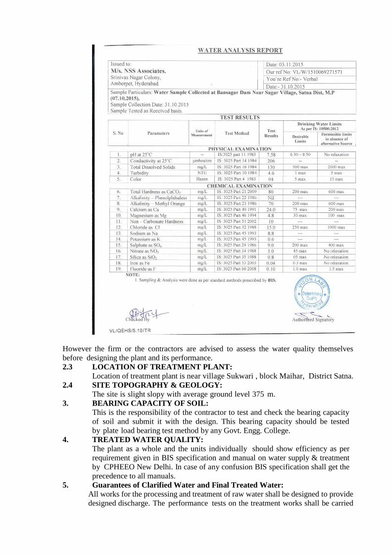
However the firm or the contractors are advised to assess the water quality themselves
before designing the plant and its performance.
2.3 LOCATION OF TREATMENT PLANT:
Location of treatment plant is near village Sukwari , block Maihar, District Satna.
2.4 SITE TOPOGRAPHY & GEOLOGY:
The site is slight slopy with average ground level 375 m.
3. BEARING CAPACITY OF SOIL:
This is the responsibility of the contractor to test and check the bearing capacity
of soil and submit it with the design. This bearing capacity should be tested
by plate load bearing test method by any Govt. Engg. College.
4. TREATED WATER QUALITY:
The plant as a whole and the units individually should show efficiency as per
requirement given in BIS specification and manual on water supply & treatment
by CPHEEO New Delhi. In case of any confusion BIS specification shall get the
precedence to all manuals.
5. Guarantees of Clarified Water and Final Treated Water:
All works for the processing and treatment of raw water shall be designed to provide
designed discharge. The performance tests on the treatment works shall be carried
out at the flow inclusive of over loading of treated water as per CPHEEO Manual
on Water Supply and Treatment..
Clarified water quality shall meet the following standards :
Turbidity - Not more than 15 NTU
Suspended solids - Not more than 15 mg/lit Residual Aluminium
- Not more than 0.5 mg/lit
Treated water quality after filtration and chlorination shall meet the following
standards :
Color - Should be free from color with 3 or less on Cobalt scale. Turbidity
- Not more than 1 NTU or less.
Suspended Solids - Not more than 2.5 mg/l
Taste & Odour - Unobjectionable
Residual aluminum- Not more than 0.2 mg/l
Coliform Organism- Nil (MPN/100/ml)
6 DETAILED SPECIFICATION OF COMPONENTS OF TREATMENT PLANT
All the units of Water Treatment Plant shall be designed on the basis of CPHEEO
Manual on Water Supply and Treatment.
6.1 INLET CHAMBER :
It shall be provided to collect the raw water form cascade aerator. It shall be
designed for designed Capacity. It shall be in R.C.C. minimum grade M-30. The
chamber shall serve the purpose of dissipating the kinetic energy of incoming
water and also provide necessary static head for flow through treatment plant,
during normal and emergent loading condition. The residual head at the end of
pumping main will be 2 m, which may be kept, is consideration during the design.
6.2 INLET CHANNEL:
It shall be designed for designed capacity with flow measuring arrangement par
shall flume type with dial type flow indicator. The raw water channel shall be
constructed in minimum grade R.C.C. M-30 concrete supported on columns at
minimum 2.00 mts, center to center in R.C.C. minimum grade M-25. A puddle
collar shall be provided to receive water.
6.2.1. FLOW MEASURING ARRANGEMENT:
The flume shall be designed for a designed flow (with a provision of 50%
over loading) with free board of not less that 30cm. The measuring flume shall
have a side chamber for float. The flume shall be open channel type. The entire
construction shall be in R.C.C. and shall be perfectly water tight and suitably
supported in R,.C.C. columns. The walkway of 1.0-meter width with G.I. pipe
railing as per specification given shall be provided. The dial type flow indicator
shall be provided near the flume to indicate the flow. The flow indicator shall have
a capacity of measuring a maximum flow of 166 million liter water in 23 hours
including 50% overloading. The weir plate will have brass edges which shall be
graduated to read in liters per hour. The weir shall operate with clear free fall
condition. It shall be ensured that the weir plates do not get submerged due to
afflux. The dial of indicator shall be properly lighted. Necessary arrangements for
proper desalting of stilling chamber shall be provided.
6.2.2. BY PASS CHANNEL
In order to provide the flexibility in operation the bypass channels shall be provided.
The by-pass channel shall be designed for designed capacity. It shall connect
the following units :-
(i) From raw water channel to flocculate by passing primary settling tank.
(ii) From raw water channel to filters by passing the flocculates and primary
settling.
(iii) From flocculate to sump by passing filters.
The necessary pens tock with simple operating arrangement shall be provided as
per
I.S. 3042-1965 or some alternative arrangement, which suits to the proposal. It
shall be constructed in minimum M-30 grade concrete and columns shall be
minimum M- 25 grade concrete.
6.3 RAPID MIXING UNIT :
It shall be flash mixer designed for designed capacity, mixer with mechanical
arrangement As per provision in Manual on water supply & treatment third
edition clause 7.4.2.
6.3.1. FLASH MIXER:
It shall be designed for detention period of 30 to 60 seconds. It shall be circular
or square tank with ratio of impeller dia to tank diameter 0.20 to 0.40 and the shaft
speed of propeller to Impart tangential velocity greater than 3mt/Sec. at the tip of
the blade. The ratio of the tank height to the diameter shall be 3:1. The power-
mixing device shall be capable of creating velocity gradient for 300 per second.
The power requirement of flash mixer shall be as per recommendation given in
I.S. 7090.
The paddles made of structural steel confirming to I.S. 226. The agitator shall
be mechanically driven consist of electric motor with continuous duty operating
through a reduction gear. To achieve good results the chemical should be added
just near the tip of blade. The design should be such that there should be no
possibility of short circuiting in the tank. It shall be designed for a full flow of
designed capacity. A desludging pipe of R.C.C. NP2 with sluice valve confirming
to B.I.S. shall be provided. The length of pipe shall be as per requirement of
layout plan, it shall be connected to waste water sump. Hand railing along
operating platform (1.0m diameter all around) of 0.75mt. height shall be provided.
The M.S. ladder of 0.75 mt. wide shall also be provided. The specification of ladder
and railing are given separately. It shall be constructed in R.C.C minimum M-25
grade concrete. Protective cover of G.I Sheet of 8 gauge shall be provided for motor.
6.4 CLARIFLOCULATOR-
Combined units of flocculation and sedimentation shall be provided immediately
after flash mixer but it should be designed on concept of tap erring velocity gradient
and settling velocity with suitable motor operated mechanical cleaning device.
6.4.1. NUMBER OF UNITS:
Clarifloculator (s) shall be provided for the total designed flow with provision for
25% overloading under emergent condition as per CPHEEO manual. The inlet and
outlet arrangement will also be designed for 25% overloading.
6.4.2. INFLOW ARRANGEMENT -
Coagulated water from flash mixer will be conveyed to the inlet of clarifloculator
through precast R.C.C. pressure pipe or CI or DI D/F of suitable dia. It should be
possible to regulate or stop flow, to individual unit. The pipes shall be laid over
firm bedding and at uniform grade. The velocity of flow through this conduit
shall preferably be between 0.25 to 0.45 mps.
6.4.3 FLOCCULATOR -
It shall be designed to provide a detention time of 30 minutes at design flow.
Other design parameter viz depth of water, velocity of flow, paddle area, peripheral
velocity of blade. Velocity gradient G and the factor GT shall be generally in
accordance with CPHEEO manual Para 7.4.3.2. Mechanical Type Flocculator.
Coagulated water will be admitted through the central hallow shaft near the water
surface and then will flow radially outwards uniformly in all directions through
slots. The velocity of flow through these slots should be about 0.2 to 0.3
m/s. Flocculation paddles 2 or 4 in numbers depending upon design will be mounted
on a vertical shaft, which will be rotated by A.C. motor 3 phase 415 v. The partition
wall and the floor slab of flocculator shall be of R.C.C. Area of opening at the
bottom of partition wall should be large enough to maintain sufficiently low
velocity of flocculated water.
6.4.4. CLARIFIER -
The Clarifier shall be designed to provide a minimum detention period of 2.0 to
2.5 hours and surface loading of 30 to 40 m3
/m2
/day at design flow. The
outlet shall comprise of V-notches and effluent launder or rectangular weir and
outlet flume. A baffle may be provided in front of the weir to stop floating matter.
A weir loading of 300 to 600 m3/day/m length may be provided.
The outer circular wall and the floor slab of the clarifier shall be of R.C.C. The
floor slab shall have a minimum slope of 1: 12. A peripheral walk way 1.2 m
shall be provided with railing for each floculator one set of 300mm dia telescopic
bleed arrangement manually operated, sluice valve extension rod and bend wheel
ISI marked shall be provided.
6.4.4.1 Sludge Removal in Plain Sedimentation Tanks and Clarifiers / Floculators
and Clarifloculators
a) The withdrawal of sludge from plain sedimentation tanks and clarifier / flocculator
/ clariflocculators be carried out into a terminal sludge collection tank for disposal
into the sludge drying beds by pumping. Suitable pump sets and pump house
have to be provided at the sludge collection tank.
b) Each plain sedimentation tank and clarifiers / flocculators / clariflocculator shall
be provided with a scraper system to direct sludge to sludge pockets for piping to
sludge control chambers. Separate draw-off pipes and valves shall be provided
for each sludge pocket.
c) Each plain sedimentation tank and clarifiers / flocculators / clariflocculator shall
be provided with a sludge control chamber. The chambers shall incorporate
equipment for both continuous and intermittent sludge draw-off. Hydrant
connections shall be provided at each chamber for flushing / washing down
purposes.
d) The sludge from the Plain sedimentation tanks and clarifiers / flocculators /
clariflocculators, shall be collected in the sludge receiving tanks. The pump
house with suitable pumping machinery shall be provided adjacent to the sludge
receiving tank for pumping out the sludge from the tank into the sludge drying
beds followed by effluent disposal to the nearby water body with environmental
acceptance and arrangement to pump this into inlet channel.
6.4.4.2 Desludging Control and Plant
Plant for the desludging system and control shall be located in the central
control house as appropriate.
Control
(i) The system shall be designed to carry out the following operations:
A) intermittent desludging alone
B) continuous desludging alone
C) intermittent and continuous desludging simultaneously.
D) Pumping of sludge from sludge receiving tank into the sludge drying
beds.
a) Clearing of Blockages
(i) Compressed air and pressure water shall be used to facilitate purging of
sludge pipes and pockets in the event of blockages.
(ii) Control of each sludge valve shall originate from a manually pre-set
electrical multi-range adjustable timer with means of independent adjustment
of frequency (time between draw offs) and duration (length of draw-off) of
desludging together with 'hand/off/auto' switching, 'state' lights (indicating
state viz. 'open/close') and associated sludge control panels. Each plain
sedimentation tank and clarifloculator shall be provided with its own
independent sludge control system, with the associated panel located in the
central control house.
(iii) Facilities for sequential sludge discharge shall be provided. Manual
override facilities both for initiation of a discharge sequence and for
operation of individual valves shall be provided. Valves controlled
automatically on an intermittent basis shall be pneumatically operated
straight through type or eccentric plug type, and shall be arranged to be
'fail safe' (e.g. on power or pneumatic failure, discharge valves shall close)
and initiate an audible and visual alarm state at the Filter control Block.
It shall be possible to open the valve manually by using a lever or similar,
under fail-safe conditions; alternative facilities such as compressed air
bottles (one for each sedimentation tank or clarifiers / floculators /
clarifloculator) or foot pumps (minimum two), shall be provided for manual
operation of valves. Each pneumatic valve shall be provided with a manually
operated guard valve and a manual bypass facility.
(iv) Continuous desludging of plain sedimentation tanks and clarifiers shall be
by adjustable bell mouth devices with cast iron bodies and bronze guides.
The devices shall be provided with operating headstocks and suitably
located position indication scales and arranged to operate in parallel with
the intermittent desludging valves.
(v) During the periods of temporary shutdown, it is required that sludge
scraping and sludge evacuation equipment shall continue to run until all
heavy solids have been removed from the system which could otherwise
compact during the shutdown period and cause difficulties on start up.
b) Hydraulic design: The total hydraulic design capacity of the sludge withdrawal
and discharge system shall not be less than 10% by volume of the Max. Water
Flow.
c) Sludge disposal pipework: The pipe work for the plain sedimentation tanks and
clarifiers / flocculators / clariflocculators sludge system (within structures) shall be
of RCC NP3 and shall enable to empty tank into the sludge well by gravity. Valves
shall be of cast iron-rubber lined type, epoxy painted outside. The valves shall
be easily accessible for manual operation. The pipe work for sludge pumping
shall be in cast iron / ductile iron.
6.4.4.3 Sedimentation Tank and Clarifiers / Flocculators / Clariflocculator
Scraping Mechanism
Sludge scrapers and mechanical flocculators Sludge scraper mechanism and
discharge arrangements shall be designed for raw water suspended solids loadings
up to 20000 mg/l for the plain sedimentation tank and 1000 mg/l solids in
clarifloccultors. The design shall allow for starting up under a sludge sit down
situations, and to accept without distortion any normal torsional or bending loads
which may occur during erection and operation, scraper mechanism shall extend to
the entire diameter of the tank.
6.4.4.4 Plain Sedimentation Tank and Clarifier Sampling :
a) Local sampling taps of approved design shall be installed to take sample from
at least three different points in each plain sedimentation tank and
clariflocculators.
b) The three sampling taps for each tank shall be grouped together and shall
discharge into a sink, which shall be connected to the main drainage system.
6.4.4.5 Drainage of Plain Sedimentation Tanks and Clarifier
Each tank shall be provided with facilities for complete gravity drainage of all
water and sludge from both the main body of tank and from sludge concentrates.
All valves, pipe work required for discharge to and connection with the main
drainage system shall be provided, so that a tank may be emptied within 6 to 8
hours. These drains shall discharge into the main works drainage duct to be
provided by the Contractor.
6.4.5 ROTATING BRIDGE-
The clarifier scraper bridge structure shall be made of welded and bolted M.S.
structural. It will be a lattice girder bridge pivoted at the center and trolley fitted
with pneumatic solid rubber tired wheel and resting on clarifier wall.
The bridge shall be 1.2 mt. wide made of welded and bolted R.S. section of
suitable size.
The scraper arm with scraper blade of suitable size fitted with rubber squeezer
shall be suspended from the top of bridge having M.S. grill walkway 8mm
thick M.S. chequered plate walk way ground flocculator drive gear. The scraper
arm shall spread across the radius of the clarifier zone and to the dia. of flocculator
zone. The bridge shall be so designed that it should also act as a hand railing or
otherwise additional double row 32mm. G.I. pipe railing light duty shall be
provided. The driving mechanism for the bridge shall rotate over the steel
fabricated track located over peripheral wall or directly over wall by rubber
tyre wheel and comprise of GEC/Kirloskar/Crompton/Jyoti make A.C. motor of
suitable rating, 4 pole horizontal foot mounted class 'B' insulation T.E.F.C. squirrel
cage motor having degree of protection as IP 55 suitable for 415 + 10 V-3 phase
50 Hz. having flexible coupling single speed worm reduction gear, duplex chain
sprocket drive, plumber block with bearing M.S. ideal and driving shaft. The
central bearing shall comprise of combined radial and thrust bearing housed in high
grade CI housing with G.M. bush for rigidity.
The bridge shall be designed to take its own dead weight with uniformly
distributed loading of 400kg/sqm. The bridge should be so braced that deflection
at mid span is less than 80mm. The central bearing assembly shall be adequately
infraction in all respect catch trays shall be provided to prevent slippage into water.
Five rings special current Collector shall be provided for each clariflocculator
for transmission of electric power through pipe laid under floor from outside to
the sub distribution board located over rotating board.
300 mm dia R.C.C. NP2 pipe and specials as required shall be provided for
each clarifier under the floor slab between sludge out let channel around inlet
well to sludge outlet chamber at periphery.
300 mm dia D/F PN-1 manually operated C.I. Non rising spindle sluice
valve confirming to B.I.S. standards and bearing ISI mark is to be provided for each
clarifloculator. One M.S. steel operating shaft with 25mm dia extension complete
with
C.I. head stock, 200 mm dia hand wheel and brass indicator plate for operation
of sluice valve for each clarifloculator is to be provided.
For each clarifier bridge 2 Nos. 450mm wide made out of M.S. black medium
class pipe to IS 1239 rung ladder painted primer and paint, fixed to clarifier bridge
structure for access inside the clarifier zone/ flocculation zone be provided.
6.5.1 FILTRATION -
Traces of suspended matter in the clarified water shall be removed by filtration.
Filter designs shall be based on the use of rapid gravity single media sand filters
using quartz sand, type being declining rate filters.
Each filter shall be hydraulically designed for an overload of 20%. Filters shall be
capable of giving a run time of at least 24 hours. The number of filters shall be in
even numbers with stand by units. All filters shall be of identical shape and size.
Each filter shall have 2 halfs. In the case of vertical flow rapid gravity sand filters;
the average rate of filtration shall be 80 to 100 lpm/sqm. The filters will be served
by an adjacent filter control block in which shall be housed the air scour and
motive power plant for valve operation and other apparatus. The main clarified
water channel shall connect to the two filter inlet channels if necessary via a
chamber. The filters shall be down-flow open rapid gravity units type or dual
media filters of the divided bed type and shall operate on declining rate principle.
All filters shall be identical in internal dimensions and shall be designed for
washing using filtered water and air scour. The air scour may precede or be
concurrent with the Wash water. The filters shall be designed so that when
receiving clarified water of the standards given in clause 2.2 the minimum period
between washes is not less than 24 hours.
6.5.2 NUMBER OF FILTER -
The filters should be in even numbers and designed for economy to filter 166
million litre treated water ( in 23 hours working ) plus about 2.0 to 3.0 times of
quantity of back wash water.
6.5.3 RATE OF FILTRATION -
The rate of filtration shall be taken as 4.8 to 6 m/hr (80 to 100 lpm/m2). The
inlet and outlet arrangements shall be designed to permit 100% overload for emergency
conditions.
6.5.4 CAPACITY OF FILTER UNITS-
The capacity of filter should be such that the number of unit can take care of the
total quantity of water to be filtered and with optimum efficiency to keep the filters working
without undue overloading at any time.
6.5.5 SIZE OF FILTER UNIT -
Where the filters are located on both sides of pipe gallery. the ratio of length to
width of a filter box shall be about 1.25 to 1.33. A minimum 2 mt depth of water shall be
provided above filter media. The filters shall be constructed in R.C.C. of minimum grade M-
30.
6.5.6 FILTER MEDIA -
Filter media will consist of sand gravel. The Specification of media shall be as
per CPHEEO manual Para 7.6.3.6 to 7.6.3.10
6.5.7 UNDER DRAINAGE SYSTEM -
The design parameters in under drainage system shall be as given in Para 7.6.3.9
of CPHEEO manual. The under drain system with central manifold or laterals either
perforated in the bottom or having umbrella type strainers on top shall be provided. The
central manifold and laterals shall be of cast iron, concrete or other suitable materials.
6.5.8 WASH WATER GUTTER (TROUGHS)-
It shall be of R.C.C. with M-30 grade it shall be designed in such a way that
the Horizontal travel of dirty water over surface of filter shall be kept in between 0.6 to
1.00 mt before reaching the Gutter. The upper edge of wash water gutter should be placed
sufficiently near to the surface of sand so that large quantity of dirty water is not left in the
filter after the completion of washing. At the same time the top of the wash water gutter
should be placed at sufficient height above the surface of the sand so that the sand will
not be washed into the gutter. The height should be considered by considering the expansion
of sand.
6.5.9 FILTER BACK WASH -
The backwash shall be arranged at such a pressure that the sand should expand
to about 130 to 150 % of its undisturbed volume. The backwash shall be of air water type.
The air shall be introduced at a rate of 36 to 45 Mt/Hr and pressure of 0.35 kg/Sq.cm for a
duration of 5 minutes and then the wash water shall be introduced through the same under
drains at a rate of 24 to 36 to cmt/hr for 10 minutes. For introducing air and water the piping
may be same or separate. it shall be worked out by the firm with due consideration to the
economy.
6.6 WASH WATER TANK -
It is advisable and economical also if wash water tank is constructed above the
clear water control chamber. Its capacity will depend on the total loss of head due to
expansion of sand. Loss in under drainage system loss in incoming pipe and height of
wash water gutter with respect to under drainage system. The bottom of wash water tank
shall be at a height of about 9.00 mt to 11.00 m, the capacity of wash water should be
varied from 2 to 6% of filtered water and should be sufficient for at least 10 minutes wash
of one filter or 5 to 6 minutes wash of two filters. The minimum capacity of tank should
be designed for washing two filters at a time. It shall be of R.C.C. with minimum grade
M-30. The most preferable shape is Rectangular. The corners of tank shall be rounded off.
The top slab of tank shall be of R.C.C. minimum grade M-30 with sufficient number of
manholes and ventilators of 100mm dia C.I. with Cowels and the aluminium ladder of 0.45
mt wide from top to bottom of tank.
A float operated mechanical gauge shall be provided. The arrangement should
be fixed in such a way that during excessive wind flow it should not be disturbed. It shall
have meter scale painted with enamel paint with black and red colour on white colour back
ground. A RCC staircase from ground to top of tank shall be provided by contractor. It
shall have the railing either on both sides or on one side as per site conditions.
6.7 APPURTENANCES -
6.7.1 RATE OF FLOW CONTROLLERS -
Since it is proposed to provide declining rate filtration hence one rate of flow
controller shall be provided. In this case filter influent shall be entered below the low
water level of filters so relatively large influent header pipe or channel will serve all the
filters. It shall be provided with influent valve for each individual filter.
6.7.2. FILTER GAUGES -
It shall be provided to measure accurately the rate or flow through each filter box
and to determine the loss of head occurring at any time during the filter run. It must be
simple in operation and easy in handling by the maintenance staff.
6.7.3 WALK WAY -
Walk way all-round the filters minimum 1.50M width shall be provided. it shall
be fitted with railing of 0.75 M height.
6.7.4 PIPE GALLERY-
Effluent wash and waste water pipes all together with the sluice valves are placed
in the pipe gallery should be well designed with minimum 2.00mt width provided with a
ladder or steel rungs to make it for the maintenance staff easily accessible to the bottom. It
should be well ventilated. It should have a sufficient slope to drain out the wash water or
other leakage water. The two pipe galleries shall be provided one gallery for effluent
pipe Air and wash water pipes and other Gallery specially for draining out the wastewater
of filters. It shall be designed by contractor and preferably of R.C.C. pipe. It shall be
connected with wastewater sump. The system will avoid the unnecessary congestion of the
pipes and avoid the hindrances in cleaning of pipe galleries. One shall be towards the module
chambers side and other towards the influent header pipe side it should be constructed with
minimum R.C.C. grade M-30.
6.7.5 EFFLUENT AND WASH WATER PIPE -
The effluent pipe shall be designed for a velocity of 0.9 to 1.8 mt./second and
wash water pipe for a velocity of 1.5 mt/second. These shall be C.I. double-flanged class
.Pipes confirming to I.S. 7181 - 1984 and C. I. specials shall be confirming to I.S. 1538-
1976. The sluice valve provided shall be confirming to I.S. 14846-2000.
6.8 MODULE CHAMBER OF CLEAR WATER CONTROL CHAMBER
It shall shave sufficient space to accommodate sluice valves of effluent pipes,
effluent discharge weir and clear water effluent pipe feeding to clear water sumps. It
shall have sufficient circulation space minimum 2.00 mt of ground floor where the module
chambers shall be minimum ceiling height of floor shall be 4.00 Mt. The ground
floor shall be easily accessible by providing aluminium ladders. Arrangement for effluent
sluice valves. air blowers piping. Wash water tank etc. It shall be framed structure of
minimum R.C.C. M-30 grade concrete. At a height of minimum 10.00 Mt. the wash water
tank shall be provided for storing the water for washing the filters. The capacity of wash
water tank is given in Para 6.6 The panels of framed structure shall be constructed of
chimney brick masonry with cement mortal 1:5 and plastered with mortar 1:5 the ground
floor as well as first floor shall have sufficient ventilation of about 30% of floor area. As
for as possible natural ventilation shall be provided the window shall be of M.S. Z-section
provided with 4 mm thick transparent glass. The gate shall be provided on all the four
sides. The main gate shall be. made of aluminium automatically closing type fitted with
glass and the other gates one towards filter sides and other towards chlorine room side
and open area side shall be made of Z section angle iron of size 1.20mt x 2.10 fitted with
glass. The windows shall be opened outside fitted with mosquito net with all arrangements
of opening and closing the window stoppers etc. complete. These shall be primed and
painted as approved by the Engineer-In-charge. The flooring in chamber shall be mosaic
with good finish upto 30-cm. height. The ground floor shall have drainage arrangement
to easily drain out water in case of cleaning the water from module chamber.
6.9 AIR BLOWER -
The Air blowers shall be designed for a free flow of air at the rate of 36 to 45
Cum/hr at a pressure of 0.35 kg/sqcm for a duration of 5 minutes. Two air blowers
including100 % standby arrangements shall be provided. The material used for the pipe and
specials should be anticorrosive preferably DI, class k-7 or C.I. Class LA double flanged
and C.I. Sluice valves confirming to I.S. 14846. These shall be mounted in clear water
control chambers at about
1.00 mt depressed floor from operating floor of effluent sluice valves.
6.10 BACK WASH WATER PUMP:-
It shall be designed for 1.00 Hr. i.e. pump shall be in position to fill wash water
tank in 1 Hr. There shall be two pumps in which one will act as stand by unit. These pumps
shall be provided on the air blower floor. The pump shall be of centrifugal type with a suitable
motor to operate on 415+10% volt, 50 Hz. B class of insulation and degree of protection
at IP-56, the suitable Auto Transformer Starter panel, Cable, suitable rating capacitors and
Stabilizer. These pumps shall be provided and fixed by the contractor. The pump shall
be provided suitably NRV, and sluice valve of PN 1.0. The size of the pipe to fill the
wash water tank shall be designed by the contractor. The pipe shall be C.I. double-flanged
class A with bell mouth at the top. The delivery pipe in wash water tank connecting to
different filter to sluice valve shall be designed by contractor and made of C.I. double-
flanged class A confirming to I.S. code in practice. The scour and over flow pipe also be
designed and provided by the contractor. The overflow pipe shall be connected with the
clear water sump pipeline or clear water sump whichever in nearer. Scour pipe shall be
connected with the waste water line of filter going to waste water sump of chamber with
necessary C.I. sluice valves.
6.11 MODULES: -
The module chamber shall be R.C.C. constructed for each filter bed separately.
It shall have two compartments. In one compartment it shall have clear water effluent pipe
with sluice valve. It shall be operated from the operating platform. The second compartment
will be used for collecting the clear water spill over the weir; the height of weir shall be
kept in order to avoid the negative head. It shall be line with tiles of standard make,
preferably in sky blue colour. The top of the module chamber shall be covered with M.S.
framed cover divided in two parts, fixed with glass of minimum 4mm thick the cover
shall be so fixed that it should be easily opened at the time of maintenance. The module
chamber shall also have arrangement for draining out the dirty water (at the time of
maintenance). The minimum 600mm. R.C.C. Class NP2 pipe with sluice valves should be
provided. The entire module chamber shall be connected with the one waste water line &
finally disposed of either in drain constructed in front of this block or in waste water
collection sump Sufficient head room above the module chamber shall be provided a M.S.
ladder from floor to the top of the module chamber shall be provided.
6.11.1 FILTER CONTROL
Filters shall be of the declining rate type with filtration rates varying by +20% of the
average over a filter run length. At the start of the filter run, when the bed is clear the
filtration rate shall be 20% above the average value whilst at the end of the filter run the
filtration rate shall be of 20% below the average value.
Clarified water shall be fed to each filter from the inlet channel through a submerged
penstock opening.
At the outlet of each filter the filtered water shall flow through an adjustable valve or
'setting valve', which shall limit the maximum flow to 20% above average flow. The valve
setting shall be adjusted during commissioning in order to achieve the required range of
filtration rates between clean bed and dirty bed conditions to within + 20% of the average
flow though the filters.
A separate valve drain shall be provided to drain the underflow chamber. Emergency access
to the underside of the filter floor shall be provided.
Filter valves and penstocks shall be fitted with electric actuators with facility for
manual operation.
Each filter shall be equipped with instruments for measurement of the differential head
across the filter bed. Measurement accuracy shall be +2% of the measured value. Each
measurement instrument shall be equipped with stainless steel needle isolating and drain
valves.
A control console for each filter shall be installed in the gallery.
These consoles shall be equipped such that the operator can initiate the backwashing
operation manually.
The control consoles for each filter shall include the following facilities and indications as
a minimum:
a) Start filter wash cycle -key operated push-button;
b) Manual/automatic key operated selector switch;
c) Filter water holding tank full-lamp;
d) Open/close push buttons for each actuated valve and penstock;
e) Open/close indication for each valve and penstock-lamp;
f) Filter ready for wash-lamp;
g) Filter washing - lamp;
h) Filter in service - lamp;
i) Filter out of service
j) Wash water pump tripped - lamp;
k) Air scour blower tripped - lamp
Filters shall be washed in sequence automatically under the control of a preset timer,
adjustable from 12 to 36 hours. Filter backwashing shall be inhibited to prevent two
filters washing simultaneously and also to prevent wash initiation when the filtered water
holding tank has insufficient water in storage.
Programmable Logic Controllers (PLCs) may be used for filter washing controls, with
each filter being controlled by a dedicated PLC with the initiation controlled by a central
PLC. PLCs shall be arranged so that failure of one unit does not disable the automatic
washing of more than one filter.
Lamps in the monitoring room shall indicate the state of each filter, i.e. filter in service,
filter washing and filter wash overdue.
Filter washing time cycles shall be manually adjusted to suit the monitored turbidity levels.
6.11.2 Filter Valves and Motive Power System
a) Butterfly valves shall be used for the filters in preference to penstocks or
sluice valves unless the penstocks or sluice valves proposed are of a size which
can be operated easily by one man.
b) Filter valves which require to be operated as part of the washing cycle shall
be operated by pneumatic power. The system shall be capable of operation in the
event of electric power failure and details shall be provided by tenderers, as to how
this will be done. The time taken to open or close any valve shall generally be
between 10-30 seconds.
c) Compressors for valve/penstocks operation duties shall be in duplicate with
duty/standby units including receivers, provided to serve only the filters. The
standby unit shall be so arranged to automatically operate if the duty unit fails and
also initiate an alarm state on the filter block control room annunciator. The
rating/capacity of each compressor shall be designed to serve a total of 3 filters,
and to enable valves on at least three filters to be operated simultaneously.
d) The compressor installation shall be designed to satisfy conditions for maximum
air demand and shall ensure the duty compressor does not start more than six
times in any hour and the running time of the duty compressor shall not exceed
35 minutes in any one hour. The standby compressor unit and receiver shall be
identical in size.
e) To avoid overheating, an integral cooling system shall be provided for each
compressor unit.
6.11.2 Piezometer Tapings
a) In two filters (to be selected by the Engineer-in-Charge's Representative), six
piezometer tapings shall be provided for each filter to determine the head loss
gradient across the media.
b) The Contractor shall provide and fix on the two filter front walls in an accessible
position (with standing platform if necessary) all the necessary puddle pipes,
strainers, manometers, tubes, calibrated scales, mounting boards and fixing
brackets, interconnecting small bore tubing, cocks and fittings.
6.12 PAVING :-
A paving in front of clear water control chamber 4.0 mt. wide shall be provided
by contractor. The paving shall be in grooved vetrified tiles good in appearance and color,
laid over M-25 cement concrete.
6.13 STAIR CASE:-
The stairs made of brick masonry in cement mortar 1:4 with anti skid tiles shall
be provided. The staircase shall be provided to connect ground level to the floor of control
room and wash water pump or air blower floor to the operating plate from of control room.
6.14.1 CHEMICAL HOUSE:
The chemicals to be added to raw water for coagulation and flocculation will be
filter alum, hydraulic lime and other coagulant aid if necessary. Looking to the characteristics
of the water only filter alum shall be sufficient. But in certain conditions where the raw
water becomes acidic in nature then hydraulic lime shall be mixed.
The minimum storage shall be for 3 months for filter alum and 3 months for
hydraulic lime and other chemicals. Store for the chemicals shall be provided below chemical
dosing room. The minimum ceiling height shall be 4 mt. In order to avoid moisture
the minimum plinth height shall be 0.90 mt. The floor should be made damp proof and it
should be filled about 0.60 mt. with sand and bituminous coating shall be provided over
it in order to avoid the moisture. The flooring shall be of concrete with acid resistance tiles
cladding on the floor & in the sides upto 2.0 mt. height. The building shall be constructed
in R.C.C. framed structure in M-25 grade concrete and panels shall be of second class brick
masonry in cement mortar 1:6 and plaster in cement mortar 1:4. The specification of brick
shall be as given in the specifications. The roof of this storage room shall have an opening
of 2x2 mt. to facilitate lifting of chemicals. The arrangement for lifting and weighting of
chemicals shall be provided by contractor from first floor of chemical house. Adequate
ventilation and lighting will be provided. It should be easily accessible to the trucks for
unloading the chemicals. The main entrance shall be 3.00 mt. wide and 3.50 mt. height
with rolling shutter. The height of alum stack should not be taken more than 2.0m with 30%
open space for passage.
6.14.2 EQUIPMENT'S FOR HANDLING CHEMICALS:
The Platform type-weighting machine 'Avery make' or equivalent of capacity
2.00 tonne for weighing the chemicals shall be provided. For transportation of chemicals
from storeroom to the solution tank, an electric operated hoist of 2.00-tone capacity of
approved make shall be provided. The chemical should be loaded in the steel tray attached
to wire rope.
6.14.3. SOLUTION TANK:
A Platform for construction of solution tank at a height of about 2.00 mt. from
first floor level shall be provided. The solution tank will be designed for the worst
condition of Turbidity for alum dosing to the designed flow. The minimum number of
solution tank shall be two so that one will be stand by unit. The capacity of tank shall be
designed for 8 Hrs. capacity with 0.30 mt. free board. The feeding arrangement shall be
automatic based on flow. It shall be designed for 10% strength of solution. The solution tank
shall be constructed in R.C.C. minimum M-30 grade and inside surface shall be lined with
acid resistance material like F.R.P. or epoxy resin. The lime solution tank shall be designed
for a dose of 5% strength of lime solution using 87% pure hydrated lime for the design
flow for the period of 8 hrs. Each tank shall have platform at least 0.75 mt. wide to
allow the worker to stand for handling the chemicals and preparation of solution the
platform shall have railing up to a minimum height of 0.75 mt. The height of the solution
tank shall not be more than 1.50 mt. from the first floor to the platform M.S. ladder 0.60
mt. wide shall be provided and it shall also be provided from solution tank platform to top
of solution tank.
6.14.4 DISSOLVING TRAYS :
The weighted chemical shall be placed into the tray. These trays shall be made up
of cement concrete with perforations both at sides and at the bottom. The weight of these
trays shall be such so as to handle easily by the workers.
6.14.5 CHEMICAL FEED DEVICES :
The solution feed device will depend upon the point of application. The pump type
of feeder shall be preferred, chemical feeder in which the solution from the chemical
solution tank shall be flown by pump through a strainer and through the float valve into the
orifice box. It shall include the necessary piping arrangement with G.M. valve for drains,
overflow, and delivery pipe as per I.S. standard. It shall also have necessary agitating
arrangement coupled with motor as per standard. It shall also have the provision to return
the excess flow to solution tank.
6.15 CHLORINATION :-
The chlorinator shall be designed for a dosing of 5mg/L. It shall be designed
for designed water flow. The chlorinator shall be vacuum type chlorinator with 100% stand
by. If any change in requirement of chlorine comes the firm may suggest and quote the rate
accordingly, the liquid chlorine shall be supplied in toners. The contractor shall have to
make arrangement for Brand new chlorine tonners with a nominal capacity of holding
one MT of liquid chlorine for minimum three months requirement. The tonners should be
as per relevant IS standard specifications. The contractor should also submit the required
test certificate and other certificate to enable these cylinders to be put into the use. These
tonners shall be taken over by the department only after these have worked up to the
satisfaction of the department, after O&M. The chlorinator shall be fixed up by the firm
with all required accessories. Due to corrosive nature of chlorine it should be conveyed
through either heavy wrought or steel pipe on flexible annealed copper to be tested for
35kg/cm2
working pressure. The long pipeline shall be avoided. The chlorine gas lines
shall be used. The gasket used shall be made or antimony lead (with 2 to 3% antimony)
or asbestos sheet. Screwed fitting shall be forged steel construction. Pressure indicators shall
have Teflon diaphragms or silver foil protectors. Pressure reducing valves shall be of bronze
or metal with a Teflon diaphragm.
6.15.1 a) The dosing rate shall be manually set and each chlorinator shall be
equipped with a 0 to 5 mg/l scale and a manual dose setter over the complete
range.
b) Mal-operation of the duty chlorination system shall be indicated in the
chlorination room and the monitoring room in order that manual changeover
to the standby system can be initiated.
c) Chlorinator shall be fitted with a pressure switch to provide an alarm in
the event of bursting disc or pressure relief to atmosphere.
6.15.2 CHLORINE HOUSE: -
It shall be situated in an isolated place and near to the feeding place in order to
avoid the long tubing. It should have at least two doors. The ventilation shall be provided
at the bottom of the floor. It shall be well lighted. In the proposed chlorinator an
auxiliary water system shall be provided. The suitable capacity of tank and a pump shall
be provided, capable of filling it with in 30 to 60 minutes. The structure shall be R.C.C.
framed with masonry panels in cement mortar 1:6 and plastered in cement mortar 1:4. The
flooring of room shall be have acid resistance tiles laid over cement concrete 1:2:4 An
exhaust at sufficient height from bottom, of 300 mm dia shall also be provided. The
ventilator shall be of aluminum Z section fixed with 4 mm thick glass in order to avoid the
corrosion; it shall be opened outside, a ramp on the main door of 2.0mt. wide to connect
the G.L. to the plinth level of chlorine house shall be provided.
6.15.3 ROOM TO STORE CHLORINE CONTAINERS:-
The capacity of the room shall be to store the minimum chlorine toners for
three months looking to the requirement of 5mg/l, average dose. The minimum space of
room shall be provided with rails and trolley as per requirement. It shall be constructed at an
isolated place near to the chlorine house for the chlorinator. It shall be constructed in R.C.C.
M-25 concrete framed structure and shall have same specification as for chlorine room.
Suitable numbers of exhaust fan of 450mm dia of G.E.C. or Khetan make or equivalent
standard make painted with Anticorrosive paint shall be provided.
6.15.4. TANK FOR NUTRALISATION OF CHLORINE:-
A solution tank of minimum size 3.0 x 3.0 x 2.0 mt shall be provided. It shall be of R.C.C.
with cladding of acid resistance tiles on all sidewalls and bottom. It should be very near to
the chlorine room and storage room and shall have easy access without obstruction. It may
be constructed below G.L. so it shall have a drain pipe 150mm dia R.C.C. class NP-2or PE
100 pipeline with sluice valve upto the nearest waste water line or upto sump.
6.15.5 EMERGENCY KIT: -
It shall consist of various tools appliances like gasket, Yokes Studs. Tie rods,
hoods, clamps, spanners, mild steel channels kits, screws pins etc. complete. It shall cover
the total precautionary arrangement parts, which shall be required at the time of chlorine
leakage. All the Gadgets shall be designed for using in controlling or stopping the leakages
from valves, fusible plugs, and sidewalls of cylinder used for handling chlorine.
6.15.6 Chlorine Residual Monitoring
a) One chlorine residual sampling and transmitting unit for settled water shall
be provided at outlet of clarifiers. Residual chlorine monitoring shall be
arranged by collecting water from the clear water reservoir.
b) The chlorine residual monitoring system shall be designed to measure
free available chlorine. The signal from the measuring cell transmitter shall
be indicated on the panel in the chlorine house with repeat indication and
recording in the Control Block monitoring room.
c) A chlorine residual recorder shall be installed as a floor mounted unit in
the chlorination room and actuated by a 4 to 20 mA signal from a residual
chlorination measurement cell mounted above ground level in the clear
water reservoir outlet chamber.
d) This cell shall be fed with a continuous supply of treated water from the
outlet main of the clear water reservoir. A suitable sampling pump shall be
supplied to feed the water to the measuring cell.
e) A signal shall be transmitted to the monitoring room and shall be used
to activate a chlorine residual indicator to be mounted in the monitoring
room panel.
f) High and low chlorine residual level alarms shall be annunciated in
the monitoring room and in the chlorination room.
g) All necessary sampling pumps, pipe work and isolation valves, for
delivering clear water to the cell shall be provided.
6.16 FIRE EXTINGUISHING - ARRANGEMENT:-
Suitable fire extinguishers shall be provided and placed in different position in
pump house and chlorine storage room besides buckets filled with sand and placed at
different places in clear water control chamber, chlorine room pump house shall also be
provided.
6.17 Water Sampling:
Continuous comparison of water samples is required and the equipment
provided shall include a suitable drained bench containing two clarity bowls
complete with all interconnecting pipe work, automatic sampling pumps and
drainage facilities for samples drawn from:
a) Raw water at the inlet works;
b) Clear water reservoir outlet.
The bench shall be sited in the reception area of the administration building.
In addition a suitable sampling arrangement shall be included in the laboratory to
enable samples to be obtained as follows :
a) Raw water at the inlet works;
b) Clarifier inlet;
c) Rapid gravity filter inlet;
d) Clear water reservoir outlet;
e) Supernatant
The sampling arrangement shall include all interconnecting pipe work,
automatic sampling pumps and taps, adequate sink and drainage, all incorporated
into a satisfactory sample bench.
In addition, convenient means shall be provided to obtain samples manually
from each filter beds outlets and sample cocks shall be provided locally at the
clear water reservoir outlet. Sludge Drying Beds
Sludge from the waste water recovery tank shall be discharged by open
impeller type sludge pumps to the drying beds. The sludge from clarifiers,
flocculators and sedimentation tanks etc., shall be pumped to the sludge drying
beds directly through a suitable designed, pumping main. The sludge drying beds
shall be with RCC M25 floor, supported by CC bed concrete of not less than
(1:3:6) prop., and with side walls of RCC M25 with proper granular material
filled up over suitable drainage system designed and laid for collecting the
filtrate and to discharge the same to the inlet chamber and arrangement to
discharge it into nearby natural drain shall also be provided.
The drying beds shall be so sized that each can contain four times the
average daily production of sludge from the waste water recovery tanks as well
as from the sludge produced from plain sedimentation tank, clarifiers / floculators
etc they shall be designed”< for a cycle period of 5 to 7 days.
Filtrate from the drying bed under drains shall be discharged in to the
inlet chamber the discharge shall meet the standards for discharge into inland
surface waters. When a drying bed is full to a depth of 200mm with dried sludge,
the sludge shall be dug out and used for landfill wherever required.
6.18 SAFETY EQUIPMENT: -
1) Self-contained air-breathing apparatus with gas mask 6 numbers.
2) Gas leakage detector orthotolodine impregnated paper type leak detection
system eight numbers.
Four chlorine gas leak detectors shall be supplied and installed, each with a
single, detector cell, two for the drum room, one for the evaporator room and
one for the chlorination room to alarm in the event of a chlorine leak.
The chlorine leak detectors in the drum room shall be mounted at each end of
the drum room. The chlorine leak detectors shall have two adjustable alarm levels
sensitive to chlorine concentrations above 1 ml/m³, and the range of adjustment
of alarms shall facilitate selection of the following alarms:
low level - 2ml/m³
high level - 4ml/m³
The low level alarm shall initiate local audible and visual alarms. The high level
alarm shall initiate local audible and visual alarms, audible and visual alarms
outside the buildings, alarms in the monitoring room, it shall shut down the
chlorination systems, isolate chlorine drums and stop all the extract fans./ Warning
signs shall be provided in English and Hindi.
3) Compressed air cylinder recharging facilities comprising of 40 litters capacity
cylinder with recharging kit to refill service cylinder or breathing apparatus - 2No.
4) Protective Clothing - Rubber & P.V.C. clothing 2 numbers.
5) First Aid Facility - Emergency Oxygen Kit 5 No. First Aid Box complete for
artificial respiration to neutralize Inhaled chlorine effect - 4 No. First Aid printed
chart. It shall be mounted on a glass framed wooden board in chlorine room.
6) Weighing Machine - The weighing machine of standard make of two tonne
capacity shall be provided to record the weight of cylinder.
7) Emergency safety showers & eye wash- the contractor shall provide two safety
showers and eye bath units. These units shall be installed at location approved
by Engineer-in-charge.
6.19 UNLOADING ARRANGEMENT: -
An arrangement with chain pulley block of 2 tons ( or appropriate) capacity at a
height of minimum
5.00 tm. supported on M.S. beam section. It shall be provided at the entrance of chlorine
storage room to unload the toners.
7.00 CLEAR WATER SUMP:-
The clear water from the module chamber shall be conveyed to the clear water
sumps either through pipe or channel designed for a velocity 0.9 to 1.8 m/sec. The selection
of pipe or channel shall be made on the basis of economy. The pipe if openly laid according
to level shall be D.I. class K-7 Tyton jonts and if covered then R.C.C. if the channel is
provided, then it should be of R.C.C. M-30 grade and covered with the R.C.C. cover slab
it shall be in horse shoe shape as for as possible. The levels shall be so fixed up so that the
tank up to water depth shall be totally underground. The tank shall be designed for a capacity
for a minimum detention period of 2 hrs. A minimum free board of 0.5 m should be provided
below the roof beam. The floor of sump shall be designed in such way that it shall have a
slope of 1:20 towards the inlet end. The shape of tank may be circular or rectangular as
per design and economy consideration preferably sump should have two compartments
connected with each other by sluice valves in order to facilitate the cleaning of sump. It
should be constructed in
R.C.C. with a minimum grade M-30 concrete and shall be provided with pressure release
system to relieve the uplift pressure. The sump should be covered at top with R.C.C. slab. The
top slab shall have adequate number of manhole chambers of size 0.9 x 1.20 m in each
compartment fixed with M.S. cover and frame painted with primer & anticorrosive paint and
locking arrangement. There should be 100 mm. dia C.I. or M.S. ventilators painted with primer
and anticorrosive paint with C.I. cowels in each quadrant of beams on the roof shall be
provided. The top of roof shall be sloped out ward to drain out rain water easily. An aluminum
ladder 0.45 mt. wide in one-man hole of both chambers shall be provided by contractor. The
inlet and outlet pipes shall be located at a diagonally opposite end in order to minimize the
short-circuiting and turbulence effect. An overflow pipe designed to maintain level shall be
provided. The scour pipe shall be laid from bottom of clear water sump to waste water sump.
All the pipes shall be fitted with sluice valve as per I.S. standard and wherever necessary
provided with inspection chambers.
A locally mounted dial type float operated level indicator to indicate the water
level shall be provided along with automatic level indication in control room.
8.00 CLEAR WATER PUMP HOUSE:-
It shall have sufficient space to accommodate required numbers of pumps for conveying
water to OHTs. There shall be one pump house of suitable size. and the minimum height shall
be provided in order to accommodate the function of Gantry. The elevation of building should
be such as to give an architectural view. It shall have one additional store room of size 6.00 x
5.00 mt. L.T. switch gear room of size 3.00 x 6.00 mt. and one office room of size 5.00 x 4.00
and attached toilet block. Additional space shall be provided for one pump set and also for
generator set if used in emergency. Sufficient minimum space between the two pumps shall be
provided for circulation and the distance of pump from the sidewall should also be minimum
2.00 mt. The distance of pumps from rear wall shall be decided to accommodate the suction
pipe, NRV, sluice valve to each pump individually. The level of pump floor may be depressed
as compared to the general floor level in pump house to avoid the negative head or negative
suction. Space for LT/HT ACB / OCB, shall also be provided for generator set if used in
emergency. The ducts for laying of electric cable from substation shall be provided. It shall be
of R.C.C. covered with chequered M.S. Plate and will have minimum size 0.6 x 0.9Mt. or
designed M-20 grade and chimney brick masonry in cement mortar 1:6 and plastered with C.M.
1:4. The capacity of the gantry crane to be provided under this contract shall be electrically
hoisting and manually moving mounted on the rails or girders to move on pumps- motors for
lifting at the time of maintenance. The floor of pump house and all other units shall be
mosaic/ironite laid over 1:2:4 cement concrete 40mm. thick. The main gate shall be of size 3.00
x 3.50mt. shall be rolling shutter, Office room, L.T. switch gear room and store room shall be
with salwood chaukhat and 40mm. thick flush doors as per I.S. specification including doors
stoppers, tower bolts etc. complete. The door or the W.C. block shall be either M.S. Fabricated
or flush doors. The window in pump house shall be about 20% of total area or provided in each
panel (except where doors are provided). The window shall also be the Z-Section fitted with 4
mm thick glass, tower bolts and all other necessary arrangements as per I.S. specification.
Minimum 12 numbers of exhaust fan 450 mm. dia shall be provided. The exhaust fan may be
G.EC. Cromption, Khetan or equivalent make. A ramp shall be provided to connect the Ground
level to the floor of pump house in main only and in other doors and in depressed floor of pump
house wherever necessary steps shall be provided. The minimum plinth height of pump house
shall be 0.60 M. It shall provide easy loading and unloading of pumps / motors from trucks by
gantry.
9.00 LABORATORY BLOCK, OFFICE AND CONTROL ROOM:-
The laboratory block may be isolated or connected with the other units. The
tentative area of laboratory block shall be 60 sqm or as per recommendation of CPHEEO
Manual on Water Supply and Treatment, whichever is more to accommodate one A.C.
Room as Control Room, Office Room, chemical room or laboratory room for testing and
attached toilet block. It shall have the same specifications as the pump house.
The contractor has to develop facility for online monitoring of water level in each
individual overhead tank/reservoir, and quantities as well as quality of water being supplied
to each overhead tank/ reservoir. Contractor has to provide online control facility for
integrating the individual data received from individual OHT/reservoir and optimize the
operation of water distribution systems control room or any other specified remote location.
The door of laboratory room & A.C. room shall be of Aluminum of size 1.20
x 2.00 Mt. self-closing type fixed with 4mm thick glass and over with rolling shutter shall
be provided (only in the laboratory room). The A.C. room shall have thermocouple ceiling
with steel bedding and PVC sheet over the mosaic flooring. The A.C. shall also be
provided by contractor. The capacity of A.C. shall be decided by contractor and of Voltas,
LG, Samsung or equivalent standard make. All around the laboratory room a platform of
1.00 Mt. wide shall be provided to put up the instruments and in two corners of wall wash
basin as per I.S. Specification fitted with water supply shall be provided. It shall have
two numbers of exhaust Fan of 300mm dia Crompton, G.E.C., Bajaj, Khetan or equivalent
make. Below the platform the Almirah for storing the chemicals fitted with wooden frames
with door shall be provided. If the laboratory block is provided isolated to the module
chamber in other building then a water sampling table, for visual examination and collection
of raw, settled filtered and chlorinated water shall be provided in laboratory room. The
testing platform and stands shall be cladded with acid resistance tiles. The following
instruments shall be provided as per I.S. Specification for laboratory by contractor.
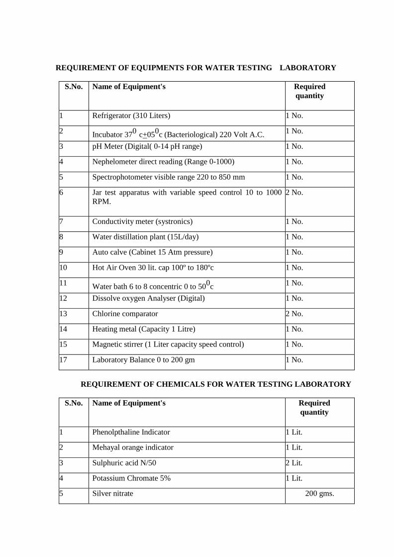
REQUIREMENT OF EQUIPMENTS FOR WATER TESTING LABORATORY
S.No. Name of Equipment's Required
quantity
1 Refrigerator (310 Liters) 1 No.
2 Incubator 37
0 c+05
0c (Bacteriological) 220 Volt A.C.
1 No.
3 pH Meter (Digital( 0-14 pH range) 1 No.
4 Nephelometer direct reading (Range 0-1000) 1 No.
5 Spectrophotometer visible range 220 to 850 mm 1 No.
6 Jar test apparatus with variable speed control 10 to 1000
RPM.
2 No.
7 Conductivity meter (systronics) 1 No.
8 Water distillation plant (15L/day) 1 No.
9 Auto calve (Cabinet 15 Atm pressure) 1 No.
10 Hot Air Oven 30 lit. cap 100º to 180ºc 1 No.
11 Water bath 6 to 8 concentric 0 to 500c 1 No.
12 Dissolve oxygen Analyser (Digital) 1 No.
13 Chlorine comparator 2 No.
14 Heating metal (Capacity 1 Litre) 1 No.
15 Magnetic stirrer (1 Liter capacity speed control) 1 No.
17 Laboratory Balance 0 to 200 gm 1 No.
REQUIREMENT OF CHEMICALS FOR WATER TESTING LABORATORY
S.No. Name of Equipment's Required
quantity
1 Phenolpthaline Indicator 1 Lit.
2 Mehayal orange indicator 1 Lit.
3 Sulphuric acid N/50 2 Lit.
4 Potassium Chromate 5% 1 Lit.
5 Silver nitrate 200 gms.
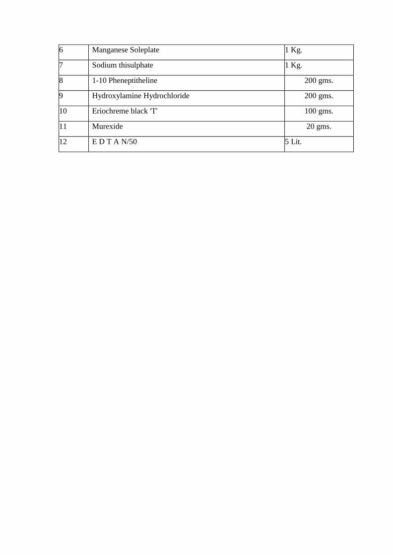
6 Manganese Soleplate 1 Kg.
7 Sodium thisulphate 1 Kg.
8 1-10 Pheneptitheline 200 gms.
9 Hydroxylamine Hydrochloride 200 gms.
10 Eriochreme black 'T' 100 gms.
11 Murexide 20 gms.
12 E D T A N/50 5 Lit.
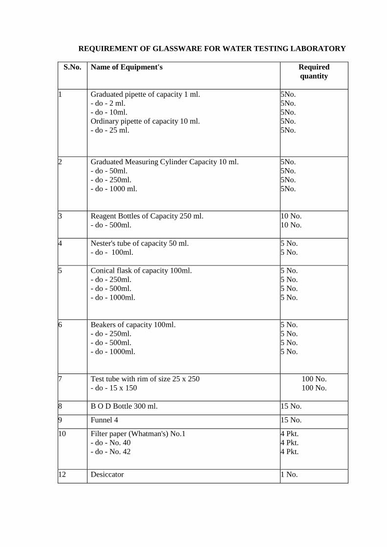
REQUIREMENT OF GLASSWARE FOR WATER TESTING LABORATORY
S.No. Name of Equipment's Required
quantity
1 Graduated pipette of capacity 1 ml.
- do - 2 ml.
- do - 10ml.
Ordinary pipette of capacity 10 ml.
- do - 25 ml.
5No.
5No.
5No.
5No.
5No.
2 Graduated Measuring Cylinder Capacity 10 ml.
- do - 50ml.
- do - 250ml.
- do - 1000 ml.
5No.
5No.
5No.
5No.
3 Reagent Bottles of Capacity 250 ml.
- do - 500ml.
10 No.
10 No.
4 Nester's tube of capacity 50 ml.
- do - 100ml.
5 No.
5 No.
5 Conical flask of capacity 100ml.
- do - 250ml.
- do - 500ml.
- do - 1000ml.
5 No.
5 No.
5 No.
5 No.
6 Beakers of capacity 100ml.
- do - 250ml.
- do - 500ml.
- do - 1000ml.
5 No.
5 No.
5 No.
5 No.
7 Test tube with rim of size 25 x 250
- do - 15 x 150
100 No.
100 No.
8 B O D Bottle 300 ml. 15 No.
9 Funnel 4 15 No.
10 Filter paper (Whatman's) No.1
- do - No. 40
- do - No. 42
4 Pkt.
4 Pkt.
4 Pkt.
12 Desiccator 1 No.
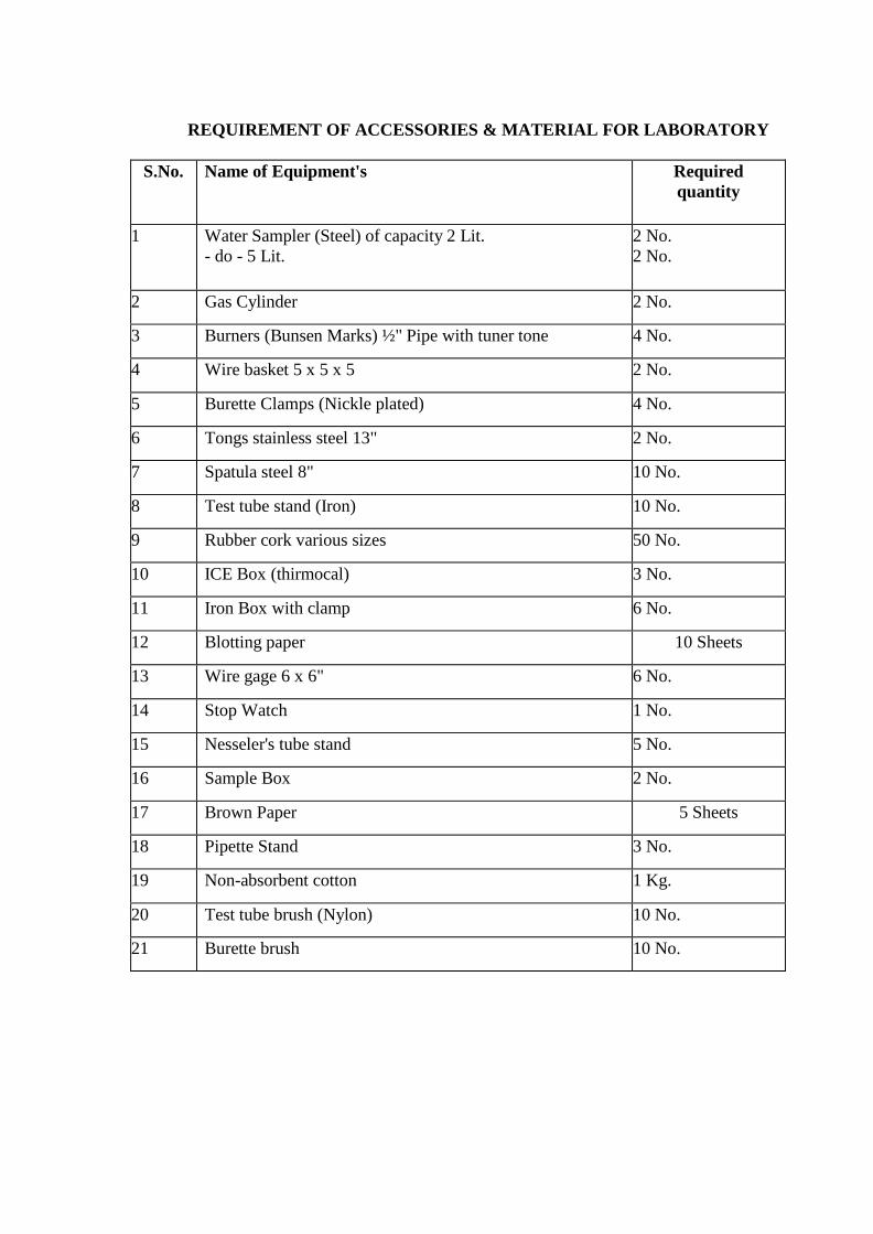
REQUIREMENT OF ACCESSORIES & MATERIAL FOR LABORATORY
S.No. Name of Equipment's Required
quantity
1 Water Sampler (Steel) of capacity 2 Lit.
- do - 5 Lit.
2 No.
2 No.
2 Gas Cylinder 2 No.
3 Burners (Bunsen Marks) ½" Pipe with tuner tone 4 No.
4 Wire basket 5 x 5 x 5 2 No.
5 Burette Clamps (Nickle plated) 4 No.
6 Tongs stainless steel 13" 2 No.
7 Spatula steel 8" 10 No.
8 Test tube stand (Iron) 10 No.
9 Rubber cork various sizes 50 No.
10 ICE Box (thirmocal) 3 No.
11 Iron Box with clamp 6 No.
12 Blotting paper 10 Sheets
13 Wire gage 6 x 6" 6 No.
14 Stop Watch 1 No.
15 Nesseler's tube stand 5 No.
16 Sample Box 2 No.
17 Brown Paper 5 Sheets
18 Pipette Stand 3 No.
19 Non-absorbent cotton 1 Kg.
20 Test tube brush (Nylon) 10 No.
21 Burette brush 10 No.
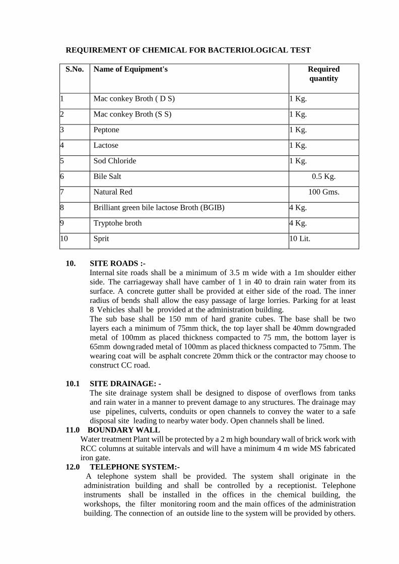
REQUIREMENT OF CHEMICAL FOR BACTERIOLOGICAL TEST
S.No. Name of Equipment's Required
quantity
1 Mac conkey Broth ( D S) 1 Kg.
2 Mac conkey Broth (S S) 1 Kg.
3 Peptone 1 Kg.
4 Lactose 1 Kg.
5 Sod Chloride 1 Kg.
6 Bile Salt 0.5 Kg.
7 Natural Red 100 Gms.
8 Brilliant green bile lactose Broth (BGIB) 4 Kg.
9 Tryptohe broth 4 Kg.
10 Sprit 10 Lit.
10. SITE ROADS :-
Internal site roads shall be a minimum of 3.5 m wide with a 1m shoulder either
side. The carriageway shall have camber of 1 in 40 to drain rain water from its
surface. A concrete gutter shall be provided at either side of the road. The inner
radius of bends shall allow the easy passage of large lorries. Parking for at least
8 Vehicles shall be provided at the administration building.
The sub base shall be 150 mm of hard granite cubes. The base shall be two
layers each a minimum of 75mm thick, the top layer shall be 40mm downgraded
metal of 100mm as placed thickness compacted to 75 mm, the bottom layer is
65mm downgraded metal of 100mm as placed thickness compacted to 75mm. The
wearing coat will be asphalt concrete 20mm thick or the contractor may choose to
construct CC road.
10.1 SITE DRAINAGE: -
The site drainage system shall be designed to dispose of overflows from tanks
and rain water in a manner to prevent damage to any structures. The drainage may
use pipelines, culverts, conduits or open channels to convey the water to a safe
disposal site leading to nearby water body. Open channels shall be lined.
11.0 BOUNDARY WALL
Water treatment Plant will be protected by a 2 m high boundary wall of brick work with
RCC columns at suitable intervals and will have a minimum 4 m wide MS fabricated
iron gate.
12.0 TELEPHONE SYSTEM:-
A telephone system shall be provided. The system shall originate in the
administration building and shall be controlled by a receptionist. Telephone
instruments shall be installed in the offices in the chemical building, the
workshops, the filter monitoring room and the main offices of the administration
building. The connection of an outside line to the system will be provided by others.
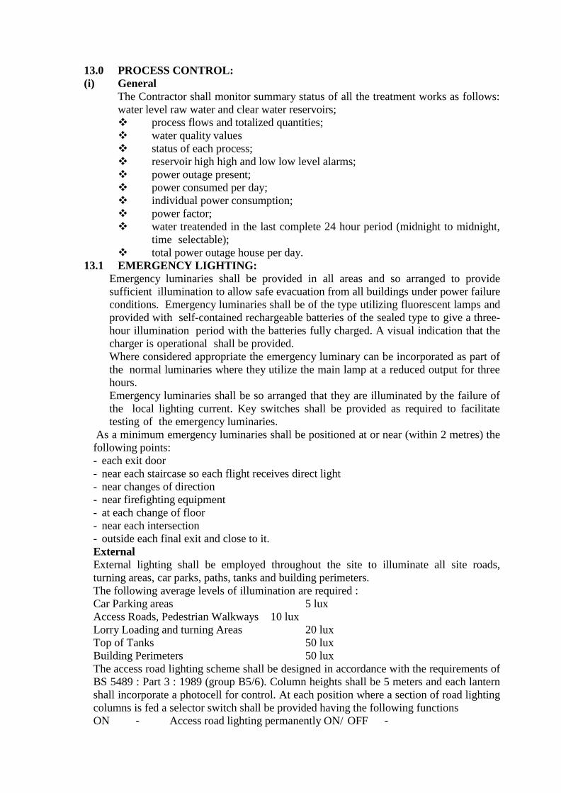
13.0 PROCESS CONTROL:
(i) General
The Contractor shall monitor summary status of all the treatment works as follows:
water level raw water and clear water reservoirs;
❖ process flows and totalized quantities;
❖ water quality values
❖ status of each process;
❖ reservoir high high and low low level alarms;
❖ power outage present;
❖ power consumed per day;
❖ individual power consumption;
❖ power factor;
❖ water treatended in the last complete 24 hour period (midnight to midnight,
time selectable);
❖ total power outage house per day.
13.1 EMERGENCY LIGHTING:
Emergency luminaries shall be provided in all areas and so arranged to provide
sufficient illumination to allow safe evacuation from all buildings under power failure
conditions. Emergency luminaries shall be of the type utilizing fluorescent lamps and
provided with self-contained rechargeable batteries of the sealed type to give a three-
hour illumination period with the batteries fully charged. A visual indication that the
charger is operational shall be provided.
Where considered appropriate the emergency luminary can be incorporated as part of
the normal luminaries where they utilize the main lamp at a reduced output for three
hours.
Emergency luminaries shall be so arranged that they are illuminated by the failure of
the local lighting current. Key switches shall be provided as required to facilitate
testing of the emergency luminaries.
As a minimum emergency luminaries shall be positioned at or near (within 2 metres) the
following points:
- each exit door
- near each staircase so each flight receives direct light
- near changes of direction
- near firefighting equipment
- at each change of floor
- near each intersection
- outside each final exit and close to it.
External
External lighting shall be employed throughout the site to illuminate all site roads,
turning areas, car parks, paths, tanks and building perimeters.
The following average levels of illumination are required :
Car Parking areas 5 lux
Access Roads, Pedestrian Walkways 10 lux
Lorry Loading and turning Areas 20 lux
Top of Tanks 50 lux
Building Perimeters 50 lux
The access road lighting scheme shall be designed in accordance with the requirements of
BS 5489 : Part 3 : 1989 (group B5/6). Column heights shall be 5 meters and each lantern
shall incorporate a photocell for control. At each position where a section of road lighting
columns is fed a selector switch shall be provided having the following functions
ON - Access road lighting permanently ON/ OFF -

Access road lighting permanently OFF AUTO -
Access road lighting under photocell control
Some flexibility in positioning of road lighting units is allowed but generally units shall
be positioned at intersections and junctions with spacing not exceeding 30 metres + 10%.
Managing Director
Madhya Pradesh Jal Nigam
Maryadit Vindhyachal Bhawan,
Bhopal
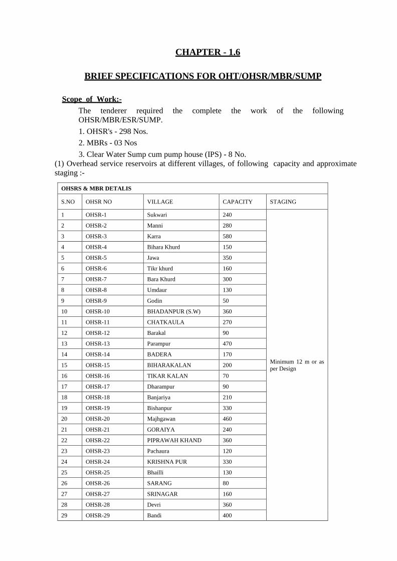
CHAPTER - 1.6
BRIEF SPECIFICATIONS FOR OHT/OHSR/MBR/SUMP
Scope of Work:-
The tenderer required the complete the work of the following
OHSR/MBR/ESR/SUMP.
1. OHSR's - 298 Nos.
2. MBRs - 03 Nos
3. Clear Water Sump cum pump house (IPS) - 8 No.
(1) Overhead service reservoirs at different villages, of following capacity and approximate
staging :-
OHSRS & MBR DETALIS
S.NO OHSR NO VILLAGE CAPACITY STAGING
1 OHSR-1 Sukwari 240
Minimum 12 m or as
per Design
2 OHSR-2 Manni 280
3 OHSR-3 Karra 580
4 OHSR-4 Bihara Khurd 150
5 OHSR-5 Jawa 350
6 OHSR-6 Tikr khurd 160
7 OHSR-7 Bara Khurd 300
8 OHSR-8 Umdaur 130
9 OHSR-9 Godin 50
10 OHSR-10 BHADANPUR (S.W) 360
11 OHSR-11 CHATKAULA 270
12 OHSR-12 Barakal 90
13 OHSR-13 Parampur 470
14 OHSR-14 BADERA 170
15 OHSR-15 BIHARAKALAN 200
16 OHSR-16 TIKAR KALAN 70
17 OHSR-17 Dharampur 90
18 OHSR-18 Banjariya 210
19 OHSR-19 Bishanpur 330
20 OHSR-20 Majhgawan 460
21 OHSR-21 GORAIYA 240
22 OHSR-22 PIPRAWAH KHAND 360
23 OHSR-23 Pachaura 120
24 OHSR-24 KRISHNA PUR 330
25 OHSR-25 Bhailli 130
26 OHSR-26 SARANG 80
27 OHSR-27 SRINAGAR 160
28 OHSR-28 Devri 360
29 OHSR-29 Bandi 400
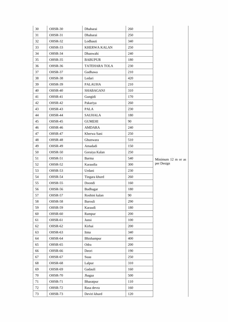
30 OHSR-30 Dhabarai 260
Minimum 12 m or as
per Design
31 OHSR-31 Dhabarai 250
32 OHSR-32 Lodhauti 340
33 OHSR-33 KHERWA KALAN 250
34 OHSR-34 Dhanwahi 240
35 OHSR-35 BABUPUR 180
36 OHSR-36 TATEHARA TOLA 230
37 OHSR-37 Gudhawa 210
38 OHSR-38 Ledari 420
39 OHSR-39 PALAUHA 210
40 OHSR-40 SHABAGANJ 310
41 OHSR-41 Gungidi 170
42 OHSR-42 Pakariya 260
43 OHSR-43 PALA 230
44 OHSR-44 SAUHALA 180
45 OHSR-45 GUMEHI 90
46 OHSR-46 AMDARA 240
47 OHSR-47 Kherwa Sani 250
48 OHSR-48 Ghunwara 510
49 OHSR-49 Amadadi 150
50 OHSR-50 Goraiya Kalan 250
51 OHSR-51 Barma 540
52 OHSR-52 Karaudia 300
53 OHSR-53 Urdani 230
54 OHSR-54 Tingara khurd 260
55 OHSR-55 Doondi 160
56 OHSR-56 Budhagar 180
57 OHSR-57 Roshini kalan 90
58 OHSR-58 Barouli 290
59 OHSR-59 Karaudi 180
60 OHSR-60 Rampur 200
61 OHSR-61 Junsi 100
62 OHSR-62 Kirhai 200
63 OHSR-63 Itma 340
64 OHSR-64 Bhishampur 400
65 OHSR-65 Odra 200
66 OHSR-66 Deori 190
67 OHSR-67 Suaa 250
68 OHSR-68 Lalpur 310
69 OHSR-69 Gadauli 160
70 OHSR-70 Jhagaa 500
71 OHSR-71 Bharatpur 110
72 OHSR-72 Rasa devra 160
73 OHSR-73 Deviri khurd 120
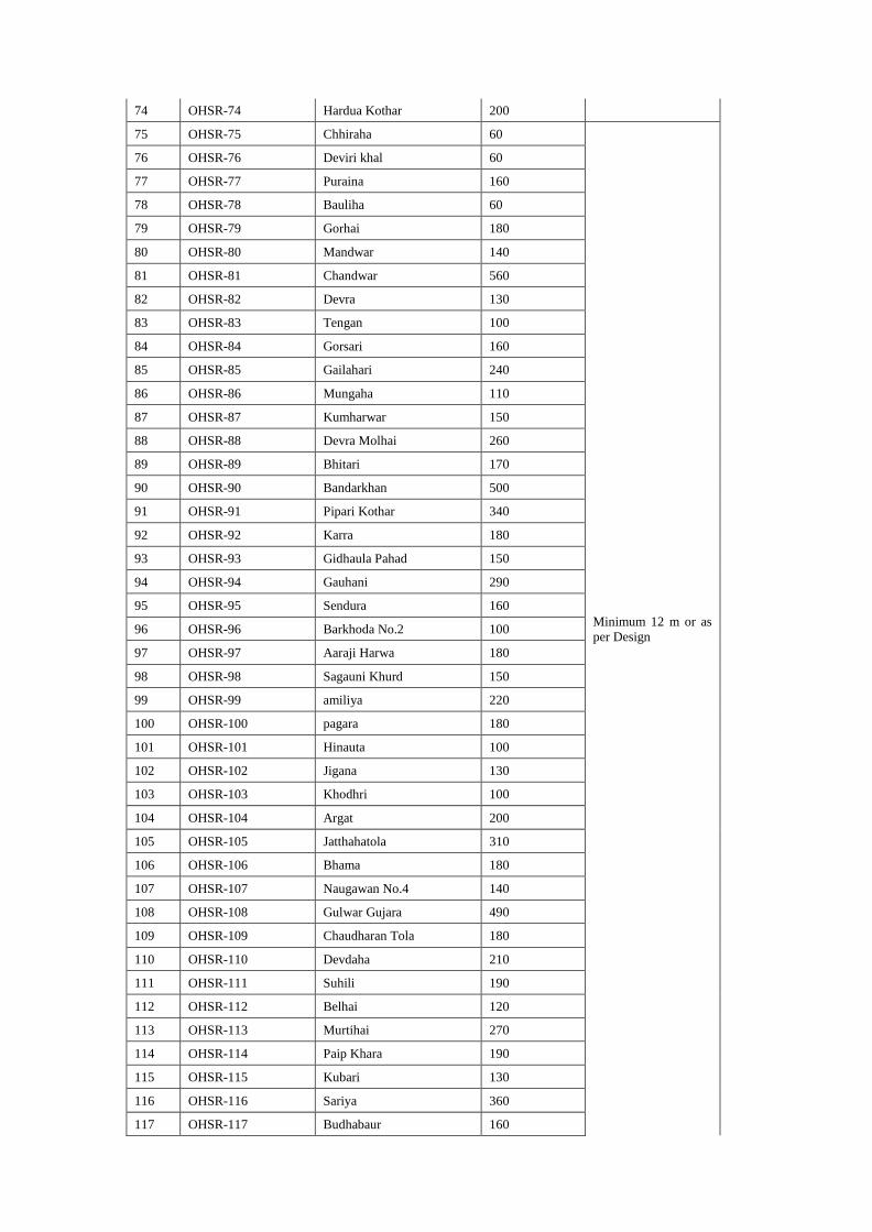
74 OHSR-74 Hardua Kothar 200
75 OHSR-75 Chhiraha 60
Minimum 12 m or as
per Design
76 OHSR-76 Deviri khal 60
77 OHSR-77 Puraina 160
78 OHSR-78 Bauliha 60
79 OHSR-79 Gorhai 180
80 OHSR-80 Mandwar 140
81 OHSR-81 Chandwar 560
82 OHSR-82 Devra 130
83 OHSR-83 Tengan 100
84 OHSR-84 Gorsari 160
85 OHSR-85 Gailahari 240
86 OHSR-86 Mungaha 110
87 OHSR-87 Kumharwar 150
88 OHSR-88 Devra Molhai 260
89 OHSR-89 Bhitari 170
90 OHSR-90 Bandarkhan 500
91 OHSR-91 Pipari Kothar 340
92 OHSR-92 Karra 180
93 OHSR-93 Gidhaula Pahad 150
94 OHSR-94 Gauhani 290
95 OHSR-95 Sendura 160
96 OHSR-96 Barkhoda No.2 100
97 OHSR-97 Aaraji Harwa 180
98 OHSR-98 Sagauni Khurd 150
99 OHSR-99 amiliya 220
100 OHSR-100 pagara 180
101 OHSR-101 Hinauta 100
102 OHSR-102 Jigana 130
103 OHSR-103 Khodhri 100
104 OHSR-104 Argat 200
105 OHSR-105 Jatthahatola 310
106 OHSR-106 Bhama 180
107 OHSR-107 Naugawan No.4 140
108 OHSR-108 Gulwar Gujara 490
109 OHSR-109 Chaudharan Tola 180
110 OHSR-110 Devdaha 210
111 OHSR-111 Suhili 190
112 OHSR-112 Belhai 120
113 OHSR-113 Murtihai 270
114 OHSR-114 Paip Khara 190
115 OHSR-115 Kubari 130
116 OHSR-116 Sariya 360
117 OHSR-117 Budhabaur 160
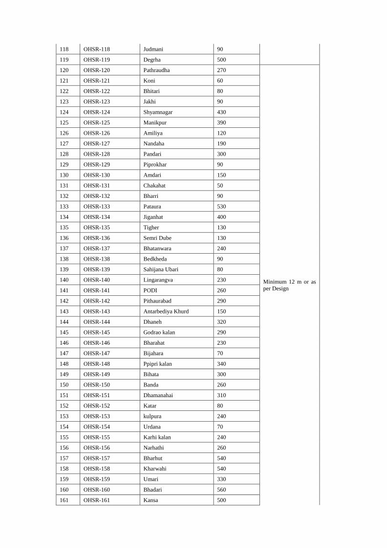
118 OHSR-118 Judmani 90
119 OHSR-119 Degrha 500
120 OHSR-120 Pathraudha 270
Minimum 12 m or as
per Design
121 OHSR-121 Koni 60
122 OHSR-122 Bhitari 80
123 OHSR-123 Jakhi 90
124 OHSR-124 Shyamnagar 430
125 OHSR-125 Manikpur 390
126 OHSR-126 Amiliya 120
127 OHSR-127 Nandaha 190
128 OHSR-128 Pandari 300
129 OHSR-129 Piprokhar 90
130 OHSR-130 Amdari 150
131 OHSR-131 Chakahat 50
132 OHSR-132 Bharri 90
133 OHSR-133 Pataura 530
134 OHSR-134 Jiganhat 400
135 OHSR-135 Tigher 130
136 OHSR-136 Semri Dube 130
137 OHSR-137 Bhatanwara 240
138 OHSR-138 Bedkheda 90
139 OHSR-139 Sahijana Ubari 80
140 OHSR-140 Lingarangva 230
141 OHSR-141 PODI 260
142 OHSR-142 Pithaurabad 290
143 OHSR-143 Antarbediya Khurd 150
144 OHSR-144 Dhaneh 320
145 OHSR-145 Godrao kalan 290
146 OHSR-146 Bharahat 230
147 OHSR-147 Bijahara 70
148 OHSR-148 Ppipri kalan 340
149 OHSR-149 Bihata 300
150 OHSR-150 Banda 260
151 OHSR-151 Dhamanahai 310
152 OHSR-152 Katar 80
153 OHSR-153 kulpura 240
154 OHSR-154 Urdana 70
155 OHSR-155 Karhi kalan 240
156 OHSR-156 Narhathi 260
157 OHSR-157 Bharhut 540
158 OHSR-158 Kharwahi 540
159 OHSR-159 Umari 330
160 OHSR-160 Bhadari 560
161 OHSR-161 Kansa 500
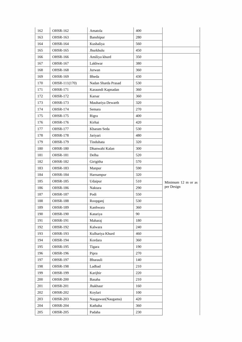
162 OHSR-162 Amatola 400
163 OHSR-163 Banshipur 280
164 OHSR-164 Kushaliya 560
165 OHSR-165 Jhurkhulu 450
166 OHSR-166 Amiliya khurd 350
Minimum 12 m or as
per Design
167 OHSR-167 Lakhwar 380
168 OHSR-168 Jurwan 360
169 OHSR-169 Bheda 430
170 OHSR-111(170) Nadan Sharda Prasad 530
171 OHSR-171 Karaundi Kapnadan 360
172 OHSR-172 Karsar 360
173 OHSR-173 Mauhariya Dewarth 320
174 OHSR-174 Semara 270
175 OHSR-175 Rigra 400
176 OHSR-176 Kirhai 420
177 OHSR-177 Kharam Seda 530
178 OHSR-178 Jariyari 480
179 OHSR-179 Tinduhata 320
180 OHSR-180 Dhanwahi Kalan 300
181 OHSR-181 Delha 520
182 OHSR-182 Girigitha 570
183 OHSR-183 Manpur 590
184 OHSR-184 Harnampur 320
185 OHSR-185 Udaipur 510
186 OHSR-186 Naktara 290
187 OHSR-187 Podi 550
188 OHSR-188 Roopganj 530
189 OHSR-189 Kanhwara 360
190 OHSR-190 Katariya 90
191 OHSR-191 Maharaj 180
192 OHSR-192 Kalwara 240
193 OHSR-193 Kulhariya Khurd 460
194 OHSR-194 Kordara 360
195 OHSR-195 Tigara 190
196 OHSR-196 Pipra 270
197 OHSR-197 Bharauli 140
198 OHSR-198 Ladbad 210
199 OHSR-199 Karijhir 220
200 OHSR-200 Basaha 210
201 OHSR-201 Jhakhaur 160
202 OHSR-202 Koylari 100
203 OHSR-203 Naugawan(Naugama) 420
204 OHSR-204 Kathaha 360
205 OHSR-205 Padaha 230
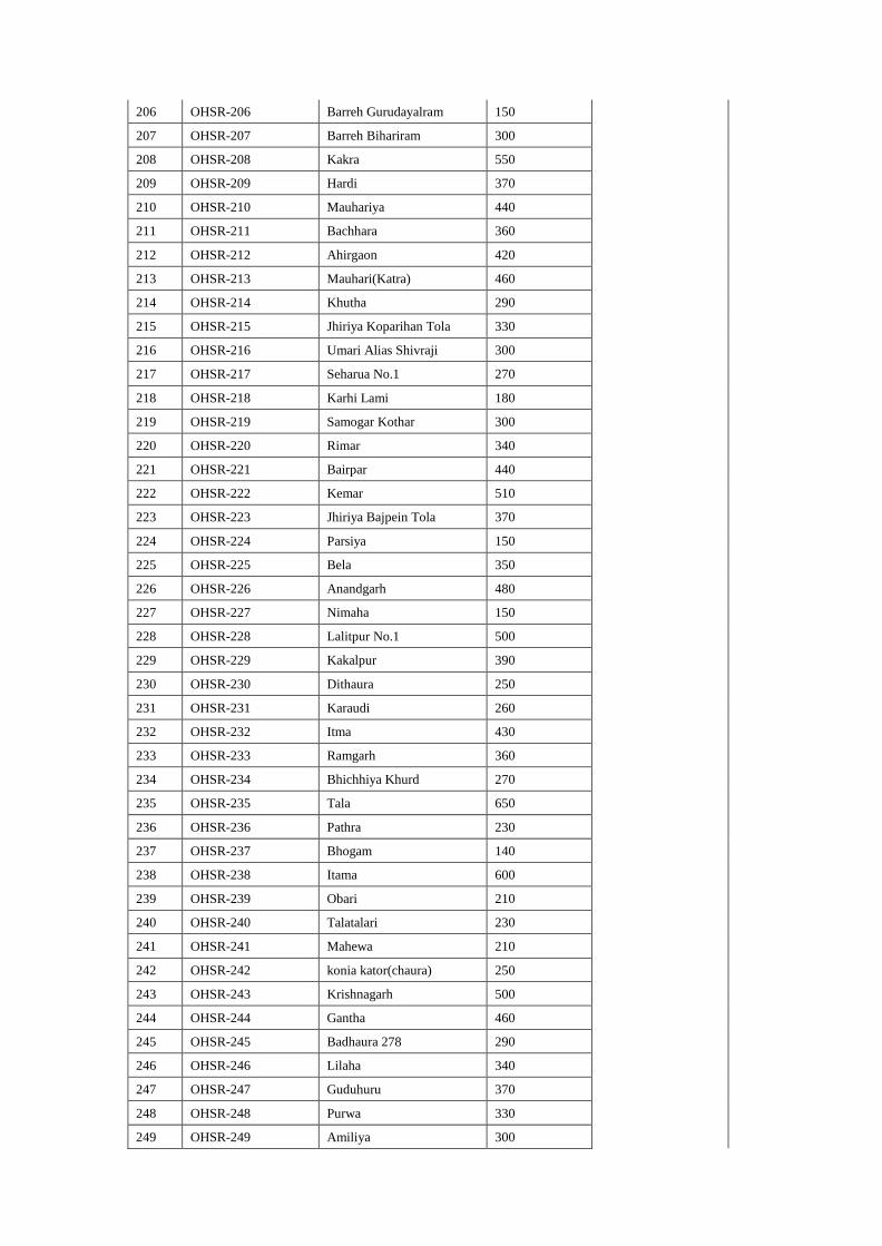
206 OHSR-206 Barreh Gurudayalram 150
207 OHSR-207 Barreh Bihariram 300
208 OHSR-208 Kakra 550
209 OHSR-209 Hardi 370
210 OHSR-210 Mauhariya 440
211 OHSR-211 Bachhara 360
212 OHSR-212 Ahirgaon 420
213 OHSR-213 Mauhari(Katra) 460
214 OHSR-214 Khutha 290
215 OHSR-215 Jhiriya Koparihan Tola 330
216 OHSR-216 Umari Alias Shivraji 300
217 OHSR-217 Seharua No.1 270
218 OHSR-218 Karhi Lami 180
219 OHSR-219 Samogar Kothar 300
220 OHSR-220 Rimar 340
221 OHSR-221 Bairpar 440
222 OHSR-222 Kemar 510
223 OHSR-223 Jhiriya Bajpein Tola 370
224 OHSR-224 Parsiya 150
225 OHSR-225 Bela 350
226 OHSR-226 Anandgarh 480
227 OHSR-227 Nimaha 150
228 OHSR-228 Lalitpur No.1 500
229 OHSR-229 Kakalpur 390
230 OHSR-230 Dithaura 250
231 OHSR-231 Karaudi 260
232 OHSR-232 Itma 430
233 OHSR-233 Ramgarh 360
234 OHSR-234 Bhichhiya Khurd 270
235 OHSR-235 Tala 650
236 OHSR-236 Pathra 230
237 OHSR-237 Bhogam 140
238 OHSR-238 Itama 600
239 OHSR-239 Obari 210
240 OHSR-240 Talatalari 230
241 OHSR-241 Mahewa 210
242 OHSR-242 konia kator(chaura) 250
243 OHSR-243 Krishnagarh 500
244 OHSR-244 Gantha 460
245 OHSR-245 Badhaura 278 290
246 OHSR-246 Lilaha 340
247 OHSR-247 Guduhuru 370
248 OHSR-248 Purwa 330
249 OHSR-249 Amiliya 300
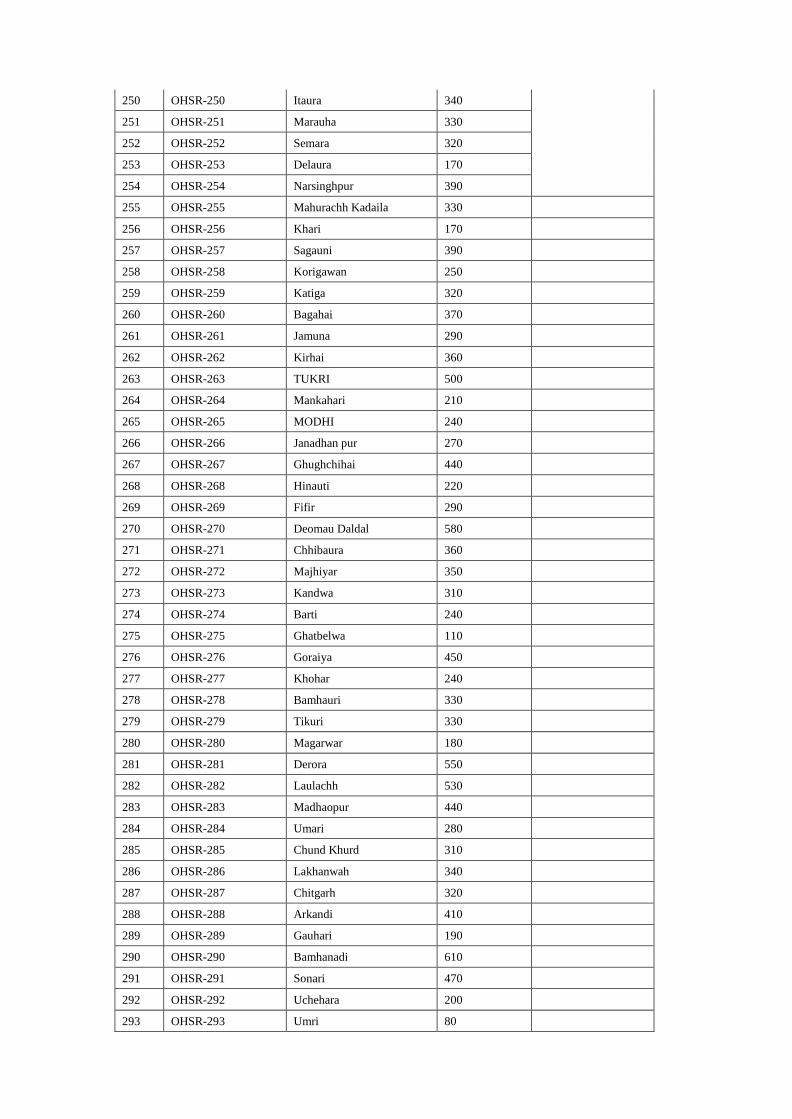
250 OHSR-250 Itaura 340
251 OHSR-251 Marauha 330
252 OHSR-252 Semara 320
253 OHSR-253 Delaura 170
254 OHSR-254 Narsinghpur 390
255 OHSR-255 Mahurachh Kadaila 330
256 OHSR-256 Khari 170
257 OHSR-257 Sagauni 390
258 OHSR-258 Korigawan 250
259 OHSR-259 Katiga 320
260 OHSR-260 Bagahai 370
261 OHSR-261 Jamuna 290
262 OHSR-262 Kirhai 360
263 OHSR-263 TUKRI 500
264 OHSR-264 Mankahari 210
265 OHSR-265 MODHI 240
266 OHSR-266 Janadhan pur 270
267 OHSR-267 Ghughchihai 440
268 OHSR-268 Hinauti 220
269 OHSR-269 Fifir 290
270 OHSR-270 Deomau Daldal 580
271 OHSR-271 Chhibaura 360
272 OHSR-272 Majhiyar 350
273 OHSR-273 Kandwa 310
274 OHSR-274 Barti 240
275 OHSR-275 Ghatbelwa 110
276 OHSR-276 Goraiya 450
277 OHSR-277 Khohar 240
278 OHSR-278 Bamhauri 330
279 OHSR-279 Tikuri 330
280 OHSR-280 Magarwar 180
281 OHSR-281 Derora 550
282 OHSR-282 Laulachh 530
283 OHSR-283 Madhaopur 440
284 OHSR-284 Umari 280
285 OHSR-285 Chund Khurd 310
286 OHSR-286 Lakhanwah 340
287 OHSR-287 Chitgarh 320
288 OHSR-288 Arkandi 410
289 OHSR-289 Gauhari 190
290 OHSR-290 Bamhanadi 610
291 OHSR-291 Sonari 470
292 OHSR-292 Uchehara 200
293 OHSR-293 Umri 80
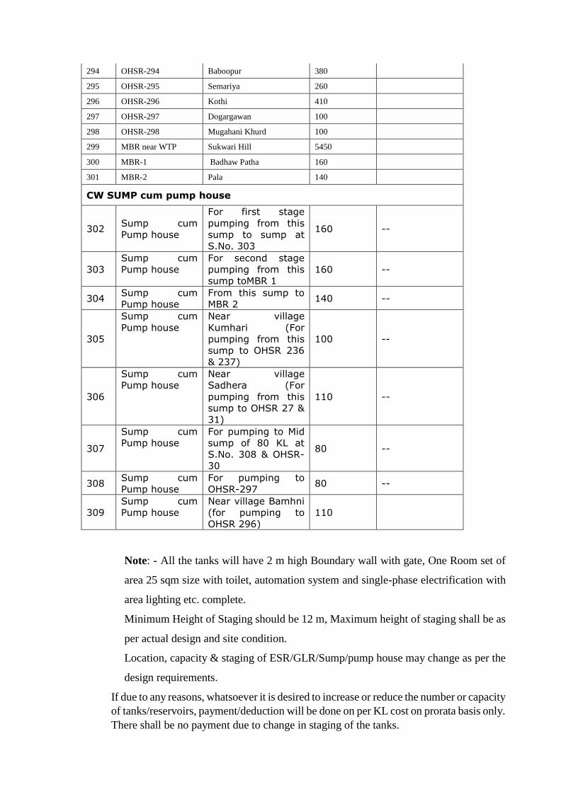
294 OHSR-294 Baboopur 380
295 OHSR-295 Semariya 260
296 OHSR-296 Kothi 410
297 OHSR-297 Dogargawan 100
298 OHSR-298 Mugahani Khurd 100
299 MBR near WTP Sukwari Hill 5450
300 MBR-1 Badhaw Patha 160
301 MBR-2 Pala 140
CW SUMP cum pump house
302 Sump cum
Pump house
For first stage
pumping from this
sump to sump at
S.No. 303
160 --
303
Sump cum
Pump house
For second stage
pumping from this
sump toMBR 1
160 --
304 Sump cum
Pump house
From this sump to
MBR 2 140 --
305
Sump cum
Pump house
Near village
Kumhari (For
pumping from this
sump to OHSR 236
& 237)
100 --
306
Sump cum
Pump house
Near village
Sadhera (For
pumping from this
sump to OHSR 27 &
31)
110 --
307
Sump cum
Pump house
For pumping to Mid
sump of 80 KL at
S.No. 308 & OHSR-
30
80 --
308 Sump cum
Pump house
For pumping to
OHSR-297 80 --
309
Sump cum
Pump house
Near village Bamhni
(for pumping to
OHSR 296)
110
Note: - All the tanks will have 2 m high Boundary wall with gate, One Room set of
area 25 sqm size with toilet, automation system and single-phase electrification with
area lighting etc. complete.
Minimum Height of Staging should be 12 m, Maximum height of staging shall be as
per actual design and site condition.
Location, capacity & staging of ESR/GLR/Sump/pump house may change as per the
design requirements.
If due to any reasons, whatsoever it is desired to increase or reduce the number or capacity
of tanks/reservoirs, payment/deduction will be done on per KL cost on prorata basis only.
There shall be no payment due to change in staging of the tanks.
General :-
[I] Construction of Ground level reservoir (sump), shall consist of two equal
compartment, all others may be with single compartment. All tanks will have central
ventilation lantern.
[II] R.C.C. Stair case and Valve chambers
[III] Pipe line arrangement including providing and laying pipes and specials of required
diameter and length.
[IV] Providing and fixing required Valves and Sluice gates.
[VI] Providing and fixing of Lightening Conductor, Water Level Indicator, Aluminium
Ladder, Railing, Manholes with locking arrangement and Ventilation hole
arrangements, internal lighting arrangement and external campus electrification etc.
[VII] Protection work all around the Reservoir, Weather Shield Apex painting, suitable
colour enamel painting, cleaning, finishing and handing over finished work to
the department.
The bidder will be required to submit detailed design, drawing, approximated quantities
of cement, steel, pipes, valves, gates and specials etc and calculation in five copies within
one month from the date of acceptance of their tender duly checked from the any IIT/NIT,
as directed by the General Manager for scrutiny and approval from competent authority.
The responsibility for design construction/structural stability and water tightness will
however rest solely with the contractor.
[I] Construction of these RCC - ESR/GLR/Sump which consists of central ventilation
shall:-
1. The reservoir shape should be circular with central dome and central
ventilation lantern so as to incorporate architectural effect to give an
impressive view. Any other shape which gives architectural impressive view
better than the above may be considered as per the decision of engineer-in-charge.
2. Free board of minimum 50cm should be provided below lowest part of roof
beam slab structure. The minimum 50cm free board should be everywhere below
bottom of straight beam, ring beam, and roof slab etc.
3. The floor level of MBR shall be so fixed, so as to provide desired water by
gravity through gravity pipelines, to proposed ESR/SUMP
4. The tenderer should assess the bearing capacity of strata at the proposed site
by conducting the required tests. It is responsibility of contractor to conduct
bearing capacity test if required and bear financial charges towards it. The
department will not make any payment towards it.
5. Design criteria
(a) Foundation shall be designed as per ascertained S.B.C. of soil as given
above and other soil parameter.
(b) The following load and forces should be considered
(i) Dead Load
(iv) Live Load – static and dynamic load due to flow and falling of water
(iii)Load due to waterWind pressure as per IS 875-1969
(v) Pressure due to Earthquake i.e. seismic force
(c) The sump shall be designed as per IS 456-2000 revised upto date and IS
3370-1976 (part I to IV) with upto date amendment and other standard code
in practice besides the stipulations made in the code.
(d) Construction joints
It should be as per clause No. 13.4 of IS 456.2000. Previously laid concrete
layer should be first cleaned by water jet and then 10mm thick layer of
cement mortar of same proportion should be laid before casting of next layer
of concrete. Formwork should be 100mm below the previously laid concrete
layer.
(e) Steel
Minimum Steel
The minimum steel for design purpose shall be as per relevant code, but
minimum steel shall be as follows:-
(i) Exposed RCC surface :- If thickness is 150mm or more both face
reinforcement shall be provided
(ii) Steel in container :- It shall be as per IS 3370 but minimum shall be as
per (i) mentioned above.
(iii)Maximum spacing of reinforcement :- The maximum spacing of main
reinforcement in slab or wall should not be more than 150mm c/c.
The spacing of secondary bars i.e. distribution steel shall not be
more than 300mm c/c.
6. The contractor shall have to make the reservoirs chlorine resistant by painting
surface with suitable Epoxy or any other material because heavy dose of
chlorination is expected to be given in water.
7. General specification
7.1 The depth of excavation will generally be guided by the underground strata and
safe bearing capacity of the soil. The foundation/mat concrete shall be laid min.
1.50m below GL. Safe bearing capacity & other soil test shall be conducted by
the contractor at his own cost. The result of SBC shall be submitted before start
of work along with the detailed structural design.
The design of foundation for OHTs, OHBRs shall not be permitted for SBC more
than 15 tonne /m2
in strata containing any type of soil, even if the reported SBC is
more than 15 tonne /m2, however, in case of rocky strata it may be considered
maximum 25 tonne /m2. No payment will be made to the contractor for carrying
out these tests or on account of change in design due to strata. No dewatering in
any condition shall be payable. The foundation shall be filled with minimum
150mm thick levelling course in cement concrete grade M-15 with 20mm metal.
7.2 All other general & common specifications shall be as per Chapter -1.
[II] R.C.C. STAIR CASE & VALVE CHAMBERS: -
[A] R.C.C STAIR CASE:-
Suitable R.C.C. Staircase of grade M-25 concrete from First Flight level to top of roof
Reservoir along circumference with G.I. railing as mentioned in the specification in Chapter
-1. Contractor shall provide an Aluminium Ladder till first flight which shall be kept at
Watchman room when not in use. The riser should be around 175 ± 25 mm and tread should
be around 275 ± 25 mm. The width of stair shall not less than 1000 mm. The landing of
minimum 1000 mm wide should be provided after 12 to 15 steps. The separate frame
structure i.e. columns and beams should be provided for staircase for the overhead tanks of
capacity 1000 kL or more. The staircase with suitable gate shall be provided to prevent
unauthorized entry on the tank.
[B] VALVE CHAMBERS:---The valve chambers for each valve of grade M-20
concrete/Brick Masonary should be constructed.
[III]P I P E LINEARRANGEMENT:----
[A] PIPES:-
[1] Each compartment shall be provided with Inlet pipe, Outlet pipe, Overflow pipe and
scour pipe . Thus, there will be one Inlet, one Outlet, one Overflow and one scour
pipe in each compartment of the reservoir.
The diameter of different type of pipes are given below.
S.No. Particulars Type of Pipe Internal Nominal
Diameter in mm.
01 Inlet pipe
lines
C.I. Class LA or D.I. D/F Class K-7/ K-9
As per Dia. of
Incoming pipe.
02 Outlet pipe
lines
--------------do------------- Next higher Dia.
than inlet or size of
main pipe of
distribution
network, whichever
is higher
03 Overflow pipe --------------do------------- Next higher Dia.
than inlet
04 Scour pipe --------------do------------- 100 mm
The inlet pipe shall be as far away from the outlet pipe as possible and outlet should be
sufficiently above the floor level so as to keep it above deposited sediment at bottom of
reservoir.
The scour pipe shall be provided at the bottom. The top of bell mouth on inlet shall
be at FTL and overflow about 5 cms. above the FTL. The overflow in any case shall
not be connected to the outlet pipe.
The cast iron or stainless steel grates of 20 mm x 20 mm on enlarge diameter of
bell mouth of outlet and scour pipes shall be provided in order to avoid the accident
during maintenance.
Specifications:-
The D.I. Double Flanged pipe should be conforming to IS:8329-2000 and while
double flanged cast iron pipe should confirm to IS:7181 latest.
(B) Specials:-
All specials required for this work of pipe line arrangement, such as duck foot bends,
puddle collars, bell mouths, bends, tees and end caps etc. shall be provided and fixed
in position as per relevant I.S.
The bell mouth required to be embedded in the concrete should be specially
manufactured with their collars as per requirement. The duck foot bend of all the
pipe shall be grouted minimum sufficiently below ground level.
(IV) Valves and Gates:-
The contractor should provide and fix in desired position the CI/DI valves
and gates for easy and effective working.
All valves should be I.S. mark and inspection and testing certificate should produce
to engineer in charge.
The double-faced sluice gate has been provided to pass water flow from one
compartment to other compartment. In close position gate face should be capable
of resisting water pressure force. There should be no leakage in closed position when
water pressure of full depth on one side and other side being empty.
For convenience in operation and maintenance of scheme, the flow controller i.e. valves shall
be of remote operation type to facilitate their operation from centralized control room at WTP
or any other specified remote location
(V) Flow Measurement:-
The arrangement for water quantity reaching to the tanks by providing & installing
in position electromagnetic flow meter of suitable diameter in inlet pipe should be
made by the contractor.
Contractor should provide arrangement such that the flow meters to be installed before
each OHT and at other place as per design shall give their reading on screen at central
control room or any other specified remote location. In addition to the above,
arrangements are also to be made for measuring of two quality parameters- residual
chlorine and turbidity at the out let of tanks and display of the same on screen at control
room or any other specified remote location.
(VI) Lightening conductor, Water level indicator, Aluminum ladder, Railing,
Manholes, ventilation holes arrangement, Internal lighting arrangement and
external campus lighting arrangements etc.
1. Lightening conductor:-
The arrangement for lightening protective system for protection of service reservoir
should be made as per I.S. 2309 – 1969 C revised up to date.
The Lightening protective system should be designed, installed and tested as per this
code and all components of the system should also be provided as per specification
mentioned in this code .
(2) Water Level Indicator: -
Each tank should be provided with water level indicator. Thus sufficient water
level indicators shall be provided in reservoir. Water level indicator shall comprise
of PVC float which should be 10 cm. more in diameter than outlet pipe. The plate
shall have turned edged to accommodate and to make easy movement of counter
weight made of iron pointer fixed with guide pulley provided with white enamel
paint write up with radium blue or black color letters. It shall be fixed on container
wall.
Contractor should provide arrangement such that the water level indicator shall display
the level of water in OHT tank on screen at central control room or any other specified
remote location.
(3) Aluminium Ladder:-
The aluminium ladder form top of roof to the inside bottom of container shall
be provided. It shall comprise of not less than 600 mm. Long double round bar
@ 250- mm. c/c. ladder shall be rigidly fixed.
(4) Railing:-
Railing should be provided on the top of roof slab along the whole circumference
and the sides of staircase as per specifications given in relevant chapter.
(5) Manhole covers:-
Manholes of minimum size 60 cms x 75 cms shall be provided. The covers shall
comprise of suitable angle iron frame and 10 gauge thick MS sheet, crossed by
suitable flat inside, with locking arrangement.
(6) Ventilators:-
The suitable air vent shall be provided as directed by Engineer-in-Charge.
(7) Electrification:-
The electrification inside and outside should be done in such a manner that standard
level of illumination is obtained inside the reservoir and in the campus. All electrical
fixtures, wires etc. shall be ISI marked. The specifications shall be as given in relevant
chapter.
(8) Float Type Valve – There shall be a float type valve for each OHSR which are fed by
gravity system.
(VII) Protection work all around the Reservoir, Weather Shield Apex painting &
colour enamel painting of approved colour, cleaning, finishing and handing over
finished work to the department :-
1.0 Protection work around sump:-
Protection work all around the sump shall be provided. It shall be circular in shape
and minimum 2.0 m in width around the outer edge of wall. It shall have 1:60
slope from center and a drain be constructed all around the tank. The protection
work shall be with M-15 grade concrete.
2.0 Weather Shield Apex painting:-
Two and more coats suitable colour Weather Shield Apex as directed by Engineer-
in- Charge shall be done after the testing of water tightness.
3.0 Colour enamel painting:-
All iron work, railing and pipes etc. shall be painted with two or more coats of
black Japan or suitable colour enamel paint over primer as directed by Engineer-in-
Charge.
4.0 Finishing:-
Although concrete shall be off shutter finish means no plaster shall be applied
over concrete to make it smooth finish, but in unavoidable circumstances if plaster
is done, then no extra payment shall be made.
5.0 Inspection & testing of concrete structure:-
5.1 In order to ensure that the construction complies with the design and all the
structural requirement, clause No. 17 of IS 456-2000 shall be followed. It should
also be noticed that during construction the settlement of sump due to self-
weight during construction should be noticed by proper procedure
5.2 Water Tightness Test
After the completion of structure it shall be tested for water tightness. Initially
the sump shall be filled gradually to ensure uniform settlement all over the area.
The full supply should reach in a period of not less than 72 hours. At the time of
testing verticality of sump should be checked by theodolite as per IS 3370 (part
I general requirement) code of practice for concrete structures for the storage of
liquids specifies water tightness test at full supply level.
After seven days period for observation after filling with water the external face
of sump should not show any sign of leakage and remain apparently dry.
5.3 The water for testing and pump for lifting water shall be arranged by the
contractor at his own cost.
5.4 The contractor shall give the test for water tightness to the entire satisfaction of
the department. The responsibility of structural stability shall solely be rest on
the contractor.
5.5 All the tanks will have a room set of area 25 sq. m with toilet etc.
5.6 All the tanks will have boundary wall of 2.00 m high and one iron gate.
5.7 All the tank will have area lighting with electrification of room and for
Electromagnetic flow meter in campus.
5.8 All the tanks & IPS will be provided with automation system as instructed by the
engineer incharge. Basic aim is to check the quantity and quality of water by
automation.
5.9 For IPSs sumps, suitable pump houses will be designed over sumps or nearby
these sumps to accommodate required nos. of pumps with all other allied
arrangements.
Managing Director
Madhya Pradesh Jal Nigam
Maryadit Vindhyachal Bhawan,
Bhopal
CHAPTER - 1.7
BRIEF SPECIFICATIONS FOR HDPE & DI DISTRIBUTION
NETWORK
BRIEF SCOPE OF WORK:-
• The scope of work shall be as given in point 1- General- Part II - brief details of work,
of this tender document.
• House service connection should be provided just inside the boundary of the consumer’s
house with the suitable MDPE pipes and ending with GI pipes and steel taps, the height of
tap must be 60 cms over ground with 15 cms nipple with rigid standing support as approved
by MPJNM.
• An RCC platform of clear size 60 cm x 60 cm in M-20 grade concrete for each house service
connection with suitable foundation should be constructed by the contractor as approved by
MPJNM
Bulk water meter: - Suitable Mechanical Jet type Bulk Water Meters should be provided at the
entry level of each village to ascertain the quantity of clear water supplied to that particular
village.
Specifications for HDPE pipes:
This specification covers the requirements for successfully designing, manufacturing,
supplying, laying, jointing and testing at works and site of High Density Polyethylene
Pipes and Ductile Iron Class K7 pipes used for water supply. Use of HDPE Pipes
shall be of pressure class of as per design requirement but minimum class of pipe
should be 6 kg/cm2 of PE 100.
Applicable Codes
The manufacturing, testing, supplying, laying, jointing and testing at work sites of
HDPE pipes shall comply with IS: 4984-1995 all currently applicable statutes,
regulations, standards and amendments and others as follows-
Code no. Title / Specification
IS 4984 High Density Polyethylene Pipes for Water Supply
IS 2530 Methods of test for polyethylene molding materials and polyethylene
compounds GRP Pipes, Joints and Fittings for use for Potable Water
Supply
IS 5382 Rubber sealing rings for gas mains, water mains and sewers.
IS 4905 Methods for random sampling
IS 7328 High density polyethylene materials for molding and extrusion
IS 7634 Laying & Jointing of Polyethylene (PE) Pipes
IS 9845 Method of analysis for the determination of specific and/or overall
migration of constituents of plastics material and articles intended to
come into contact with foodstuffs
IS 10141 Positive list of constituents of polyethylene in contact with food stuffs,
pharmaceuticals and drinking water.
IS 10146 Polyethylene for its safe use in contact with foodstuff, Pharmaceuticals
and drinking water.
Colour
The color of the pipe shall be black.
Materials
The material used for the manufacturer of pipes should not constitute toxicity hazard,
should not support microbial growth, should not give rise to unpleasant taste or odour,
cloudiness or discoloration of water. Pipe manufacturers shall obtain a certificate
to this effect from the manufacturers of raw material by any internationally reputed
organization as per the satisfaction of the Engineer-in- Charge in charge.
Raw Material
(a) Resin used to manufacture the HDPE pipes shall be 100% virgin PE Black pre-
compounded confirming to IS: 4984, IS: 7328 and ISO: 4427-2007 (latest version).
The resin proposed to be used for manufacturing of the pipes should also comply
with the following norms as per ISO 9080-2003 (latest version).
(b) The resin should also have been certified by an independent laboratory of
international repute like Bodycote / Slevan / Advantica for having passed 10,000
hour long term hydrostatic strength (LTHS) test extrapolated to 50 years to show that
the resin has a minimum MRS of over 10MPa. There should not be any brittle knee
at 80O
C before 5000 hours. Internal certificate of any resin manufacturer will not be
acceptable.
(c) Certificate from reputed organization OR Raw material supplier for having passed
the full scale rapid crack propagation test as per ISO 13478. High density
Polyethylene (HDPE) used for the manufacture of pipes shall conform to designation
PEEWA-50-T-003 of IS 7328. HDPE conforming to designation PEEWA-50- T-003
of IS:7328 may also be used with the exception that melt flow rate (MFR) shall not
exceed 1.10 g/10 min. In addition the material shall also conform to clause 5.6.2 of
IS:7328.
(d) The specified base density shall be between 940 kg/ m³ and 958 kg/ m³ (both
inclusive) when determined at 27°C according to procedure prescribed in IS 7328
The value of the density shall also not differ from the nominal value by more than 3
kg/ m³ as per 5.2.1.1 of IS 7328. The MFR of the material shall be between 0.20 and
1.10 (both inclusive) when tested at 190°C with nominal load of 5 kgf as determined by
method prescribed in IS 2530. The MFR of the material shall also be within ± 20 percent
of the value declared by the manufacturer.
(e) The resin shall be compounded with carbon black. The carbon black content in the
material shall be within 2.5 ±0.5% and the dispersion of carbon black shall be
satisfactory when tested as per IS:2530.
Anti-oxidant
The percentage of anti-oxidant used shall not be more than 0.3 percent by mass of
finished resin. The anti-oxidant used shall be physiologically harm less and shall be
selected from the list given in IS:10141
Reworked Material
No addition of Reworked/ Recycled Material from the manufacturer’s own rework
material resulting from the manufacture of pipes is permissible and the vendor is
required to use only 100% virgin resin compound.
Maximum Ovality of Pipe
The outside diameter of pipes, tolerance on the same and ovality of pipe shall be as
given in table 2 of IS 4984. Ovality shall be measured as the difference between
maximum outside diameter and minimum outside diameter measured at the same
cross section of the pipe, at 300 mm away from the cut end. For pipes to be coiled
the ovality shall be measured prior to coiling. For coiled pipes, however, re- rounding
of pipes shall be carried out prior to the measurement of ovality.
Detectability
HDPE Pipes shall be detectable when buried underground, by providing an insulated
copper wire having minimum diameter of 1.20 mm, firmly attached along the entire
length of pipe.
To avoid theft or dislocation during handling / laying or earth refilling in trench, the
insulated Copper wire shall be firmly fixed on the outer surface of HDPE pipe at Pipe
manufacturer’s works through external adhesion or co-extrusion or any other
appropriate method. The Contractor shall supply 5 sets of Ultrasonic Metal detection
instruments, suitable for on-site detection of under-ground buried HDPE pipelines,
without any extra cost and will also arrange for training of the department's personnel.
Length of Straight Pipe
The length of straight pipe used shall be more than 6 m or as agreed by Engineer-in-
Charge.
Coiling
The pipes supplied in coils shall be coiled on drums of minimum diameter of 25
times the nominal diameter of the pipe ensuring that kinking of pipe is prevented.
Pipe beyond 110mm dia shall be supplied in straight length not less than 6m.
Workmanship / Appearance
Pipes shall be free from all defect including indentations, delaminating, bubbles,
pinholes, cracks, pits, blisters, foreign inclusions that due to their nature degree or
extent detrimentally affect the strength and serviceability of the pipe. The pipe shall
be as uniform as commercially practicable in colour opacity, density and other
physical properties as per relevant IS Code or equivalent International Code. The
inside surface of each pipe shall be free of scouring, cavities, bulges, dents, ridges
and other defects that result in a variation of inside diameter from that obtained on
adjacent unaffected portions of the surface. The pipe ends shall be cut clearly and
square to the axis of the pipe. IS 4984 :1995 will be followed for visual appearance.
Handling, Transportation Storage and Lowering of pipes
During handling, transportation, storage and lowering, all sections shall be handled
by such means and in such a manner that no distortion or damage is done to the
section or to the pipes as a whole.
The following procedures should be followed so as to eliminate potential damage to
pipes and fittings and to maintain maximum safety during unloading, lifting and
lowering.
• Pipes must not be stored or transported where they are exposed to heat sources
likely to exceed 60oC.
• Pipes shall be stored such that they are not in contact with direct sunlight,
lubricating or hydraulic oils, petrol, solvents and other aggressive materials.
• Scores or scratches to a depth of greater than 10% or more of wall thickness are
not permissible; any pipes having such defects should be strictly rejected.
• PE pipes should not be subjected to rough handling during loading and unloading
operations. Rollers shall be used to move, drag the pipes across any surface.
• Only polyester webbing slings should be used to lift heavy PE (>315mm) pipes
by crane. Under no circumstances, chains, wire ropes and hooks be used on PE
pipes.
• Pipes shall not be dropped to avoid impact or bump. If any time during handling
or during installation, any damage, such as gouge, crack or fracture occurs, the
pipe shall be repaired if so permitted by the competent authority before
installation.
• During coiling care should be taken to maintain the coil diameter at or above the
specified minimum to prevent kinks. Coiling shall be done when the pipe attains
the ambient temperature from the extruder. In uncoiling or recoiling care should
be taken that sharp objects do not scour the pipe.
• When releasing coils, it must be remembered that the coil is under tension and
must be released in a controlled manner. The end of the coil should be retained at
all times, then the straps released steadily, one at a time. If the coil has bands at
different layers of the coil, then they should be released sequentially starting from
the outer layers. The amount of the energy locked up in the coil will depend on
the size of the pipe, the SDR of the pipe, and the size of the coil.
• Straight lengths should be stored on horizontal racks giving continuous support to
prevent the pipe taking on a permanent set
• Bare coils shall be wrapped with hessian cloth for long distance (> 300Kms)
transportation. The truck used for transportation of the PE pipes shall be
exclusively used of PE pipes only with no other material loaded – especially no
metallic, glass and wooden items. The truck shall not have sharp edges that can
damage the Pipe.
• Pipes manufactured at factory are to be carried to the site of work directly or
stacked suitably and neatly along the alignment/road side/elsewhere near by the
work site or as directed by the Engineer-in-Charge.
• Damages during transit, handling, storage will be to the Contractor’s account and
replacement for such pipes has to be made by the Contractor without any extra
cost as directed by the Engineer-in-Charge.
Lowering, Laying of Pipes
• Each pipe shall be thoroughly checked for any damages before laying and only
the pipes which are approved by the Engineer-in-Charge shall be laid.
• While installing the pipes in trenches, the bed of the trench should be level and
free from sharp edged stones. In most cases, the bedding is not required, as long
as the sharp and protruding stones are removed, by sieving the dug earth, before
using the same a backfill material. While laying in rocky areas suitable bed of
sand or gravel should be provided. The fill to about 10 to 15 cm above the pipe
should be fine sand or screened excavated material. Where hard rock is met with,
bed concrete M15, 15 cm or 20cm thick sand bed as approved by the Engineer-in-
Charge may be provided
• As PE pipes are flexible, long lengths of fusion-jointed pipes having joints made
above ground can be rolled or snaked into narrow trenches. Such trenches can be
excavated by narrow buckets.
• During the pipe laying of continuous fusion jointed systems, due care and
allowance should be made for the movements likely to occur due to the thermal
expansion/contraction of the material. This effect is most pronounced at end
connections to fixed positions (such as valves etc) and at branch connections.
Care should be taken in fixing by finishing the connections at a time the length of
the pipe is minimal (lower temperature times of the day.)
• For summer time installations with two fixed connection points, a slightly longer
length of PE pipe may be required to compensate for contraction of the pipe in
the cooler trench bottom.
• The final tie-in connections should be deferred until the thermal stability of the
pipeline is achieved.
• The flexibility of polyethylene pipes allows the pipe to be cold bend. The fusion
jointed PE pipe is also flexible as the plain Pipe. Thus the total system enables
directional changes within the trench without recourse to the provision of special
bends or anchor blocks. However, the pipe should not be cold bend to a radius
less than 25 times the OD of the pipe.
• The Installation of flanged fittings such as connections to sluice/air/gate valves
and hydrant tees etc., requires the use of stub ends (collars/flange adaptors
complete with backing rings and gaskets. Care should be taken when tightening
these flanges to provide even and balance torque.
• Provision should be made at all heavy fittings installation points for supports
(such as anchoring of the flange in the soil) for the flange joint to avoid the
transfer of valve wheel turning torque on to the PE flange joint.
• PE pipe is lighter than water. Hence care should be taken for normal installations
where there could be a possibility of flooding of the trench thus the trench shall
be kept free of water till the jointing has been properly done
• When flooded, some soils may lose cohesiveness, which may allow the PE pipe
to float out of the ground. Several design checks are necessary to see if
groundwater flotation may be a concern. Obviously, if the pipeline typically runs
full or nearly full of liquid, or if groundwater is always below the pipe, flotation
may not be a significant concern.
• However, weights by way of concrete blocks (anchors) are to be provided so that
the PE pipe does not float when suddenly the trench is flooded and the soil
surrounding the pipe is washed away. Thus site conditions study is necessary to
ensure the avoidance of flotation.
• Pipe embedment backfill shall be stone-free excavated material placed and
compacted to the 95% maximum dry density.
• Anchoring of the pipeline
Thrust blocks shall be provided at each bend, tee, taper, end piece to prevent
undue movements of the pipeline under pressure. They shall be constructed as
per design approved by the Engineer according to the highest pressure during
operation or testing of the pipes, the safe bearing pressure of the surrounding
soil and the friction coefficient of the soil.
• Measurement and payment
The net length of pipes as laid or fixed shall be measured in running meters
correct to a cm. Specials shall be included and measured in the total length.
The portion of the pipe at the joints (inside the joints) shall not be included in
the length of pipe work.
• Excavation and preparation of trenches for laying underground pipeline:- The trench
shall be so dug that the pipe may be laid to the required alignment and at required
depth. For road cutting and restoration of concrete/ BT roads, estimates are
based on conventional method. However, as directed by the Engineer in Charge,
the contactor is required to complete this work either (i) with concrete cutter/
trenching machine, or (ii) using trenchless technology. When the pipeline is
under a roadway, a minimum cover of 1.2 m shall be provided, in other cases
the minimum cover of 1 m above the top surface of the pipe shall be provided.
The trench shall be shored, wherever necessary and kept dry so that the
workman may work therein safely and efficiently. Under roadway and places
where it is not possible to lay pipes up to required depth or laid open on ground,
pipes should be incased all-round with the 1:2:4 (M15) cement concrete.
• Recovery of other serviceable material:-
All serviceable materials such as wood work, bricks, masonry etc. recovered during
the operation of cleaning or excavations, which, in the opinion of the Engineer-in-
Charge are suitable for reuse in restoring the surface, shall be separately stacked and
disposed-of as directed by Engineer-in-Charge.
• Dewatering:-
Dewatering shall be carried out by the contractor, wherever necessary. The discharge
of the trench dewatering pumps shall be conveyed either to drainage channels or to
natural drains and shall not be allowed to spread over in the vicinity of work place.
• . Trenching:-
• The trench shall be so dug that the pipe may be laid to the required alignment
and at required depth. For road cutting and restoration of concrete/ BT
roads, estimates are based on conventional method. However, as directed
by the Engineer in Charge, the contactor is required to complete this work
either (i) with concrete cutter/ trenching machine, or (ii) using trenchless
technology. When the pipeline is under a roadway, a minimum cover of 1.2
m under major roads shall be provided, in other cases the minimum cover
of 0.9 m above the crown of the pipe shall be provided, if due to the any
condition the pipe are not laid at prescribed depth, deduction will be made
as per UADD ISSR May 2012. The trench shall be shored, wherever
necessary and kept dry so that the workman may work therein safely and
efficiently. Under roadway and places where it is not possible to lay pipes
up to required depth or laid open on ground shall be encased all round with
the 1:2:4 ( M15) cement concrete.
Jointing of Pipes
The pipe shall have Electro-fusion jointing system that shall provide for fluid
tightness for the intended service conditions.
Bedding, Backfilling and Compaction
Bedding
In case of sandy strata no separate bedding is required. However the bottom face /
trench bed where pipe shall be placed shall be compacted to provide a minimum
compaction corresponding to 95% of maximum dry density. The pipe bedding should
be placed so as to give complete contact between the bottom of the trench and the
pipe. The minimum cover over buried pipe should be 1 m.
Back Filling
Backfilling should be placed in layers not exceeding 15cm thickness per layer, and
should be compacted to a minimum of 95% maximum dry density. The refilling
should be done on both sides of pipe together & height difference in earth fill on each
side should not be more to cause lateral movement of pipe.
Most coarse grained soil are acceptable. This may comprise of gravel or sand.
However silty sand, clayey sand, silty and clayey gravel shall not be used unless
proposed to be used in conjunction with gravel or clean sand.
It is very important that the pipe zone backfill material does not wash away or
migrate in to the native soil. Likewise, potential migration of the native soil in to the
pipe zone backfill must also be prevented.
Heavy earth moving equipment used for backfilling should not be brought until the
minimum cover over the pipe is 90 cm in the case of wide tracked bulldozers or 120
cm in the case of wheeled roaders or roller compactors.
Compaction
Vibratory methods should be used for compaction. Compaction within distances of
15 cm to 45 cm from the pipe should be usually done with hand tempers. The
backfill material should be compacted not less than 95% of maximum dry density.
Thrust Block
RCC thrust block should be suitably designed & provided at bends and at places of
reduction in cross section to take care of thrust
Fittings & Specials
All HDPE fittings/ specials shall be of minimum PN 10 or above Pressure class,
fabricated in accordance with IS: 8360 (Part I & III). PE Injection molded fittings
shall be as per IS: 8008 (Part I to IX). All fittings/specials shall be fabricated or
molded at factory only. No fabrication or molding will be allowed at site, unless
specifically permitted by the Engineer-in-Charge. Fittings will be welded on to the
pipes or other fittings by use of Electro- fusion process.
Bends
HDPE bends shall be plain square ended conforming to IS: 8360 Part I & III
Specifications. Bends shall be molded.
Tees
HDPE Tees shall be plain square ended conforming to IS: 8360 Part I & II
Specifications. Tees may be equal tees or reduced take off tees. Tees shall be
molded.
Reducers
HDPE Reducers shall be plain square ended conforming to IS: 8008 Part I & VII
Specifications. Reducer must be molded.
Flanged HDPE Pipe Ends
HDPE Stub ends shall be square ended conforming to IS: 8008 Part I & VI
Specifications. Stub ends will be welded on the pipe. Flange will be of slip on
flange type as described below.
Slip-On Flanges
Slip-on flanges shall be metallic flanges covered by epoxy coating or plastic powder
coating. Slip-on-flanges shall be conforming to standard mating relevant flange of
valves, pipes etc. Nominal pressure rating of flanges will be PN10.
Electro Fusion Tapping Saddle, Branch Saddle & Electro Fusion
fittings :
a. All the Electro fusion fittings should be manufactured with top quality virgin
pre-compounded PE 100 resin which should be compatible with the distribution
mains.
b. The products shall comply with the requirements of EN 12201-3, EN 1555-
3 or ISO 8085-3.
c. All the fittings shall be of SDR 11 rating.
d. The fittings shall have the approval from any o n e o f t h e three agencies
like KIWA, DVGW, WRC-NSF, U.K., CIPET etc.
e. All the products shall be manufactured by injection molding using virgin
compounded PE 100 polymer having a melt flow rate between 0.2- 1.4 grams/10
minutes and shall be compatible for fusing on PE 100 distribution mains
manufactured according to the relevant national or international standards. The
polymer used should comply with the requirements of EN 12201 -1.
f. Process voltage of all saddles must not exceed a maximum of 40 volts.
g. The heating elements should be designed for fusion at any ambient temperatures
between -5 to +40 degree centigrade.
h. The heating coils contained in each individual saddle should be so designed
that only one complete process cycle is necessary to fully electro fuse the
fitting to the adjoining pipe or pipeline component as applicable. The heating
coils shall be terminated at terminal pins of 4.0 or 4.7 millimeter diameter.
i. No heating element shall be exposed and all coils are to be integral part of
the body of the fitting.
j. The EF tapping / branch saddles should be fixed by fixation device and shall
be achieved by external or integral clamping device.
k. The cutter should be designed in such a way that the cut coupon is not allowed
to fall into the pipeline and is retained inside the body of the cutter.
l. A limited path style fusion indicator acting for each fusion zone as visual
recognition of completed fusion cycle should be incorporated into the body of
each fitting near the terminals. The fusion indicators should not allow the
escape of the molten polymer through them during or after the fusion process.
m. All the sockets in the electro fusion fittings should include a method of tapping
controlling the pipe penetration (pipe positioner /stopper).
n. All the electro fusion products should be individually packed in transparent
protective bags to allow easy identification without opening the bag and must
clearly indicate its contents
o. The brand name, size, raw material grade, SDR rating and batch identification
are to be embedded as part of the injection molding process. Each fitting should
also be supplied with a Data Card or stickers with appropriate barcode as well as
manual setting information for data transfer purpose.
p. Installation and Fusion Jointing
The fusion jointing process is to be carried out is as per the procedure outlined
in the DVS2202 standard, if not available equivalent standards acceptable to
employer.
A protocol for each fusion joint to be printed to ensure the joint process carried
out is error free. The electro fusion machine shall have the facility to record &
make print for each joint.
The precautions & measures as mentioned by electro fusion fittings/ machine
manufacturer should be taken up rigorously while making the joints in the
field.
The jointing procedures shall be performed with required accessories and tools
as recommended by the fittings manufacturer.
The related pipe jointing accessories such as rotary pipe cutter, Universal
clamping tools, Pipe cleaners, Pipe peelers supplied by the same electro fusion
fitting/machine supplier shall be used to ensure perfect jointing.
The usage of tapping tools such as taping keys, supplied by the same electro
fusion fitting /machine supplier must be used to ensure perfect tapping of
main lines.
The piping system will be tested as per the guidelines given by ISO standard.
The guideline shall be furnished by the supplier of electro fusion fittings,
tools and machines.
Hydraulic Testing
Pipes shall be given different hydraulic tests for ensuring quality of manufacturing as
per relevant clauses of IS specifications or prevalent standards as decided by the
engineer.
Manuals
Technical Manual on PE pipes including precautions to be taken during operation of
the pipeline.
Flanges
All flanges employed in the project must be compatible whatever material used.
Marking
All pipes shall be marked as per Clause 10 of IS 4984-1995.
Packing & Transport
The pipes should be preferably transported by road from the factory and stored as
per the manufacturer specifications to protect damage.
Summary of quality Tests:
1. Quality Mark : Pipe: IS 4984
2. Material : As per IS 4984. However only virgin resin is
allowed, reworked material is not allowed.
3. Grade of Material : PE 100 as per IS 4984 (Certificate from raw material
manufacturer is required).
4. Pressure Rating : Minimum PN 6 or above as per requirement.
5. Colour : as per IS 4984
6. Dimensions of Pipe :
Diameter : The nominal diameter (outside)
Wall thickness : As per IS 4984.
Length :
i. For diameter 90 mm and 110 mm : 100 meter (if pipes are supplied in length
less than 100 m than the cost of extra joints will be borne by the contractor.)
ii. For diameter more than 110 mm : minimum 6 meter.
(Tolerance as per IS 4984)
7. Visual Appearance : as per IS 4984.
8. Test and sampling : as per IS 4984.
9. Special Test : Notch hydraulic Test for the HDPE pipe made from
PE-100 grade raw material as per ASTM 1474 OR
ISO 13479 at manufacturers laboratory or
independent laboratory and should pass the
Hydraulic test as per IS:4984:1995 for a minimum
165 Hours. The test reports shall not be more than
three months old.
Pipe shall convey water under variable temperature
conditions ranging from 4 degree centigrade to 45
degree centigrade.
10. Jointing of pipes (pipe end):
All diameters : Electro-fusion Process
11. Quality Assurance : Quality Assurance Plan shall be got approved from
the employer before production start.
Note: All remaining parameters / specifications are as per respective BIS
specifications.
Inspection & Testing:
The inspection and testing of the sample pipes shall be carried out as per relevant IS
and/or ISO standards (latest version) by the CEIL (Certification Engineers
International Ltd.) or CIPET (Central Institute of Plastic engineering & Technology)
or any other agency approved by the MPJNM, in the manufacture's works before
dispatch and / or picking random samples of pipe from the work site.
Field Hydraulic testing of the pipelines Sectional
tests
After laying and jointing the pipeline shall be tested for tightness of barrels and
joints, and stability of thrust blocks in sections approved by the Engineer-in-Charge
in Charge. The length of the sections depends on the topographical conditions.
Preferably the pipeline stretches to be tested shall be between two chambers (air
valve, scour valve, bifurcation, other chamber).At the beginning, the Contractor shall
test stretches not exceeding 1 km. After successful organization and execution of
tests the length may be extended to more than 1 km after approval of the Engineer-
in-Charge in Charge. The hydraulic testing shall have to be commenced immediately
after laying and jointing of 1 km reach is completed.
The water required for testing shall be arranged by the contractor himself. The
Contractor shall fill the pipe and compensate the leakage during testing. The
Contractor shall provide and maintain all requisite facilities, instruments, etc. for the
field testing of the pipelines. The testing of the pipelines generally consists in three
phases: preparation, pre-test/saturation and test, immediately following the pre-test.
Generally, the following steps are required which shall be monitored and recorded in
a test protocol.
• Complete setting of the thrust blocks.
• Partial backfilling and compaction to hold the pipes in position while leaving the
joints exposed for leakage control
• Opening of all intermediate valves (if any)
• Fixing the end pieces for tests and after temporarily anchoring them against the
soil (not against the preceding pipe stretch) at the lower end with a precision
pressure gauge and the connection to the reciprocating pump for establishing the
test pressure at the higher end with a valve for air outlet
• If the pressure gauge cannot be installed at the lowest point of the pipeline, an
allowance in the test pressure to be read at the position of the gauge has to be
made accordingly
• Slowly filling the pipe from the lowest point(s). The water for this purpose shall
be reasonably clear and free of solids and suspended matter
• Complete removal of air through air valves along the line.
• Closing all air valves and scour valves.
• Slowly raising the pressure to the test pressure while inspecting the thrust blocks
and the temporary anchoring.
• Keeping the pipeline under pressure for the duration of the pre-test / saturation of
the lining by adding make-up water to maintain the pressure at the desired test
level. Make up water to be arranged by Contractor himself at his own cost.
• Start the test by maintaining the test pressure at the desired level by adding more
make-up water; record the water added carefully and the pressure in intervals of
15 minutes at the beginning and 30 minutes at the end of the test period.
The pipeline stretch will pass the test if the water added during the test period is not
exceeding the admissible limits. No section of the pipe work shall be accepted by the
Engineer-in-Charge until all requirements of the test have been obtained.
Back filling
Water used for testing should not be carelessly disposed off on land which would
ultimately find its way to trenches
On completion of a satisfactory test any temporary anchor blocks shall be broken out
and stop ends removed. Backfilling of the pipeline shall be completed.
Flushing and disinfecting of pipelines
After testing and commissioning the contractor shall flush the pipes with a velocity
not less than 1 m/s or as approved by the Engineer-in-Charge. Disinfection of drinking
water pipelines should be done by Contractor.
House Service Connections on HDPE pipes--
MDPE Pipes (PN 12.5 for 25 to 50mm Dia. and PN 16 for 16 to 20 mm dia. As per
ISO 4427 / 1996)
These specifications are for MDPE Blue/Black PE 80/100 Pipes for House Service
Connections of Dia 20 mm to 32 mm OD.
Performance requirements
The Pipe supplied should have passed the acceptance test as per ISO 4427. The
manufacturer should provide the test certificates for the following tests-
1. Melt Flow Rate
2. Density,
3. Oxidation and Induction test,
4. Hydrostatic Test ,
5. Pigment dispersion Test,
6. Longitudinal Reversion Test.
Sluice Valves on Branches/ Scour valves/ Air Valves-
Suitable numbers of CI/DI sluice valves shall be provided conforming to IS: 14846 at
different locations to regulate or isolate the flow in the network with locking chambers.
Scour Valves of CI/DI sluice valves shall be provided conforming to IS: 14846 at
different locations for emptying the pipeline for cleaning purposes with locking
chambers.
ISI marked Air valves of CI/DI shall be provided, wherever necessary with locking
chambers.
GM/ Brass Ferrules-
The ferrules for connection with HDPE shall generally conform to IS: 2692/1984
(Reaffirmed 2005). It shall be of nonferrous materials with a CI bell mouth cover and
shall be fitted with a screw and plug or valve capable of completely shutting off the water
supply to the communication pipe, if and when required.
The size of ferrule should not exceed a quarter of the nominal diameter of the main and
also be less than the size of the service pipe/connection pipe.
Compression Fittings-
Compression fittings used for House service connection should comply as per ISO 14236
with Threaded metal inserts –SS 304 with BSP Threads
Pressure Testing-
The pressure rating of compression fittings should be as per clause 8 of ISO 14236
which shall be PN16
Dimensions-
The Dimension of compression fittings shall be as per clause 7.1 of ISO 14236
Performance Requirements-
The compression fittings shall be tested as per ISO 14236. Following Test methods
shall be performed.
• -Leak tightness under internal pressure.
• Leak tightness under Internal Vacuum.
• Long term Pressure Test for Leak tightness for assembled joint
• MRS Value as per ISO 9080
• Resistance to Internal pressure.
Effects on Quality of Water-
The Compression fittings for intended for conveyance of Potable water for Human
consumption to be tested to comply with BS 6920 specifications in any of the
laboratories like DVGW / KIWA / SPGN / WRC –NSF and certificate of compliance
to be produced for the following parameters:
a. Odor & Flavor of Water.
b. Appearance of Water.
c. Growth of Micro Organism
d. Extraction of substances that may be of concern to Public Health (Cyto Toxicity)
e. Extraction of Metals.
All fittings with threaded ends should be with BSP threads.
House Service Connections on Metallic pipes--
1. Specifications for Clamp Saddle Service Connections for other pipes: Clamp saddles
for service connection from water distribution mains shall be of wrap around design, wide
skirt and wide straps support, which shall reinforce the pipe while providing excellent
stability to the saddle. Clamp Saddles for service connections shall be of fastened strap
type with threaded outlet for service connection. The service connection threading
sizes shall be conforming to IS: 554 Clamp saddles shall be suitable for DI pipes of
nominal size 3” (NB
80) to 12” (NB 300) with nominal service connection size from ½” (NB 15), ¾” (NB 20),
1” (NB 25), 1¼” (NB 32), 1½” (NB 40) and 2”( NB 50). The straps shall be elastomer
coated (insulated) type for firm grip on pipe as well as to protect the coating on the
pipe and to insulate the un-identical metals.
The saddles shall be single strap type up-to pipe sizes of NB 600 and service outlet of
½”, ¾” and 1”.The saddles shall be double strap type for pipe sizes above NB 600 or when
the service outlet is 1 ¼”, 1 ½” or 2”. Fasteners shall be of threaded nut-bolt-washer type.
Nut- bolts of size ½” (M12) shall be used for saddles of size up to 4” (NB 100) and Nut-
bolts of size 5/8” (M16) shall be used for saddles of size 6” (NB 150) and above.
The sealing between the saddle and mains shall be obtained by using a profiled elastomer
seal matching to the curvature of the pipe. The seal shall be of elastomer type, suitable
for all potable water applications. The Material of construction of the body, straps,
fasteners etc. shall be of a non-corrosive material such as engineering plastic (PE/PP)
or stainless steel or a combination of both or DI with epoxy coating. The design of
the saddle body should be such that, the service connection outlet metal insert shall
project out towards pipe side and align with the hole drilled on the pipe to ensure positive
locking against rocking or creeping on the pipe, as might be caused by vibration,
pressure or excessive external loading. The clamp saddles shall be suitable for maximum
working pressures up-to 10 bars.
1.1. Material and Design Specifications: Saddle Body: Non corrosive Engineering Plastic
body molded with Stainless steel/DI with epoxy coating threaded metal insert for
tapping outlet. Also, the stirrup metal plate shall be duly embedded in the plastic
body, except at the place of nut-bolt lugs. Threading size and dimensions shall
conform to IS:
554. The body shall have retaining cavity housing for internal and external retention
of the elastomeric seal. Sealing shall be achieved by pressure exerted by the body
while fastening the saddle straps & body on the pipe.
Saddle Strap: Saddle straps shall be made of stainless steel 304 grade / plastic strap
to prevent corrosion over the long service life.
Strap Insulation: Elastomeric (rubber) insulation / lining shall be such that none of
the Stainless Steel Strap is in direct contact with the pipe. It shall ensure a firm non
slip grip mounting on the pipe to prevent the saddle from rocking or creeping on
the pipe, as might be caused by vibration, pressure or excessive external loading.
Saddle Seal: It shall be virgin rubber SBR Grade 30 / NBR (NSF 61 approved). It
shall be of type pressure activated hydro-mechanical design. It shall be contoured
gasket to provide a positive initial seal which increases with increase in the line
pressure. Gasket shall be gridded mat, with tapered ends, with the outlet section having
O-ring contacting the saddle body multiple O-rings contacting the pipe, preferably
with a Stainless steel reinforcing ring insert molded to prevent expansion under
pressure.
Nuts- Bolts- Washer: Stainless Steel Type 304, NC rolled thread, Tightening torque
for ½” (M12) nut-bolt: 14-15 kg.m and for 5/8” (M 16) nut-bolt: 21-23 kg.m
Specifications for DI Class K7/K9 pipes:
The pipes will be centrifugally cast (spun) Ductile Iron pipes for Water confirming to the
IS 8329: 2000 / ISO 2531-1998 /BS EN 545 (latest). The pipes used will be either with
push on joints (Rubber Gasket Joints) or Flanged joints. The class of pipe to be used shall
be of the class K-7/K9 as per design.
The pipes shall be coated with Metallic zinc with a finishing layer of Bituminous Paint as
per IS: 8329.
The pipes will be supplied in standard length of 4.00, 5.00, 5.50 and 6.00 meters length
with suitably rounded or chamfered ends. Each pipe of the push on joint variety will
also be supplied with a rubber EPDM gasket. Any change in the stipulated lengths will be
approved by the Engineer. The gaskets will conform to the IS 5382:1985/ISO Standard.
The gaskets should also be supplied by the manufacturer of the pipes. They should
preferably be manufactured by the manufacturer of the pipes. In case they are not, it will be
the responsibility of the manufacturer of the pipes to have them manufactured from a
suitable manufacturer under its own supervision and have it tested at his/subcontractors
premises as per the contract. The pipe manufacturer will however be responsible for the
compatibility and quality of the products.
The flanged joints will conform to the Clause 6.2 of IS 8329/ISO Standard. Supply will also
include one rubber gaskets for each flange.
Inspection and Testing
The pipes will be subjected to following tests for acceptance:
· Visual and dimensional check as per Clause 13 and 15 of IS 8329/ISO standard
· Mechanical Test as per Clause 10 of IS 8329/ ISO standard
· Hydrostatic Test as per Clause 11 of IS 8329/ ISO standard
· The test reports for the rubber gaskets shall be as per acceptance tests of the IS: 5832
. The sampling shall be as per the provisions of the IS: 8329/ISO standard Marking
All pipes will be marked as per Clause 18 of IS 8329 and show as below:
· Manufacturer name/ stamp
· Nominal diameter
· Class reference
· A white ring line showing length of insertion at spigot
Packing and Transport
The pipes should be preferably transported by road from the factory and stored as per
the manufacturer specifications to protect damage
Hydraulic Testing
Factory test shall be as per IS:8329/ISO standard and field hydraulic test shall be carried
out for the distribution network at pressure 12 kg/ sq. cm.
Specials for Ductile Iron
Pipes General
This specification covers the general requirements for Ductile Iron (DI) fittings suitable
for Tyton joints to be used with Ductile Iron pipes with flanged and Tyton jointing system.
Types of specials
The following types of DI fittings shall be manufactured and tested in accordance with
IS: 9523 or BS: 4772/ ISO standard.
· flanged socket
· flanged spigot
· double socket bends (900, 45
0, 22 1/2
0, 11 1/4
0)
· double socket branch flanged tee
· all socket tee
· double socket taper
· retrained joints
. Collars
All the fittings shall be of class K-12
Supply
All the DI fittings shall be supplied with one rubber ring for each socket. The rubber ring
shall confirm to IS: 12820 and IS: 5382 as described in the preceding chapter.
Flanged fittings shall be supplied with one rubber gasket per flange and the required number
of nuts and bolts.
Lubricant for ductile iron pipes and specials
General
This section covers the requirements for lubricant for the assembly of Ductile Iron pipes
and specials suitable for Tyton push-in rubber ring joints.
Specification
The lubricant has to have the following characteristics:
· must have a paste like consistency and be ready for use
· has to adhere to wet and dry surfaces of DI pipes and rubber rings
· to be applied in hot and cold weather; ambient temperature 0 to 50
°C, temperature of exposed pipes up to 70 °C
· must be non-toxic
· must be water soluble
· must not affect the properties of the drinking water carried in the pipes
· must not have an objectionable odor
· has to inhibit bacterial growth
· must not be harmful to the skin
· must have a shelf live not less than 2 years
Acceptance tests
· They shall be conducted in line with the provisions of the IS 9523
Packing
All the DI fittings shall be properly packed with jute cloth. Rubber rings shall be packed
in polyethylene bags. Rubber rings in PE bags and nuts, bolts etc. shall be supplied in
separate jute bags.
The fittings should also be supplied by the manufacturer of the pipes. They should
preferably be manufactured by the manufacturer of the pipes. In case they are not, it will be
the responsibility of the manufacturer of the pipes to have them manufactured from a
suitable manufacturer under its own supervision and have it tested at his/sub-contractors
premises as per the contract. The pipe manufacturer will however be responsible for the
compatibility and quality of the products.
Summary of Quality Tests
Scope:
Supply of Ductile Iron (DI) pipe with EPDM rubber gasket for Drinking water.
Specification quality Standard
· Pipe : IS 8329/ ISO standard
· Jointing Material (EPDM rubber gasket) : IS 5382
· Classification of Pipe : Class – K- 7/K9
· Joint : Push-on-Joint (as per IS 8329/ISO standard)
· Sampling: as per respective
IS· Test: as per respective IS.
Dimensions of pipe
· Length : standard length of 4.00, 5.00, 5.50 and 6.00 meters
(tolerance as per IS 4984).
· Diameter : The nominal diameter (inside)
· Wall Thickness : as per IS 8329
Coating : Metallic Zinc with finishing layer of bituminous paint as per IS : 8329
Lining : Cement Mortar as per IS : 8329
Type of Cement : Portland Cement or Sulphate Resisting Portland Cement (as Per IS: 8329)
Quality Assurance: Quality Assurance Plan shall be got approved from the Engineer in
Charge before production start.
CHAPTER-1.8
BRIEF SPECIFICATIONS FOR RAW WATER/CLEAR WATER
PUMPING EQUIPMENTS
Scope of work:-
1.1.1 Pumps:
Vertical turbine pumps and centrifugal pumps as above complete with base plate,
sub floor discharge head, motor stool, Bowel assembly, pressure gauges etc. as
per the specifications.
1.1.2 Motors:
440 V, 3 phase, 50 cycle A.C. Solid shaft vertical motors to drive the above
mentioned vertical turbine pumps with space heaters and all other accessories as
per the specifications.
1.1.3 Capacitors:
Capacitor banks for each of above motor to improve the power factor up to at least
0.95 with accessories as per specifications attached- as per requirement
1.1.4 Starters: Auto transformer type suitable for motors shall be installed.
1.1.5 Delivery pipes and specials for pumps:
i) Suitable diameter M.S. Pipe and specials epoxy coated for delivery piping
of each of turbine pumps in the required length as per specification attached.
ii) Suitable size M.S. epoxy coated pipe for common manifold of required length.
iii) Dismantle joint as per dia. of delivery pipe.
1.1.6 Valves for delivery piping:
i) Suitable diameter swing type reflux valve (non-return valve) as per
the specifications.
ii) Suitable dia. butterfly valves as per specifications
iii) Suitable dia. butterfly valve to be installed in the manifold as per
the specifications.
iv) Suitable dia. Swing type reflux valve (non-return valve) for manifold.
1.1.7 Flow Measuring Device:
Electromagnetic full bore type flow measuring device to be installed at junction
point of pumping main and manifold outside the pump house with remote flow
indication panel to be fixed inside the pump house- one no.
1.1.8 Electronic Pressure Transducers:
For indication of delivery pressure of each pump electronic pressure transducers
with indication panel.
1.1.9 Crane:
5Ton capacities overhead gantry traveling crane
1.1.10 a) H.T. switchgear as per specifications.
b) L.T. switchgear as per specifications.
1.1.11 Temperature scanner panels as per specifications.
1.1.12 Earthing of electrical equipment's inside pump house and electrical substation as
per
I.E. rules- as required.
1.1.13 Power and control cables of suitable rating including cable trays, conduits cable
trenches, supporting materials etc. for inter connection of various electrical units
in every pumps house- as required.
i) Street lighting M.S. tubular poles for yard and street lighting with complete
fitting suitable to carry three- phase line with necessary foundation,
ii) Suitable cable conductors of suitable size from lighting distribution panel of
pump house.
iii) Distribution board for indoor/outdoor lighting.
iv) Complete water tight 250 watt mercury vapour lamp fitting on each pole to
provide illumination as desired.
v) Lightening protection of pump house building complete with earthling
stations, earthing conductors and accessories as required,
vi) Hand gloves and shock treatment charts in English and Hindi,
vii) Rubber mats in suitable sections to be provided in front of all switch boards for
their entire length,
viii) Danger/caution notice boards in English and Hindi as per I.E. rules.
1.1.14 Necessary civil work required for erection with supply of building materials, all
foundation bolts, washers‟ bolts of special design and special embedment as
required for erection including all other miscellaneous articles, e.g. lubricants and
oils required for installation, testing, commissioning, trial run and O&M.
1.1.15 Contractors shall carryout the actual site survey for determination of electrical
soil resistively.
1.2.1 All the equipment's shall be designed for operation in tropical humid climate subject
to heavy rainfall and frequent thunderstorms with ambient air temperature of
50oC a maximum and 45
oC average over 24 hours. The design of indoor
equipment shall be done for an ambient temperature of 50.c However, equipment
and apparatus to be installed outdoor subject to direct incidence of sunrays shall be
designed for operation at maximum ambient temperature of 55oC Maximum
monthly mean relative humidity is 80%, which shall be taken into consideration for
design of equipment.
1.2.2 All the materials to be used in this work must be strictly in accordance with relevant
B.I.S.
1.2.3 The work shall be carried out by a licentiate class A contractor authorized under
I.E. rules 1956 framed to in accordance with I.E. Rules of 1910. The contractor will
have to obtain the license from the M.P. inspector of electrical safety department
permitting to carry out the work.
1.2.4 The work shall be carried out strictly in accordance with latest I.E. Rules in vogue
and relevant Indian standards. (B.I.S.)
1.2.5 The pumping sets shall be installed over the properly designed foundation so as
to satisfy true alignment and vibration free installation, dynamically and statically
balanced. The installation should conform to the modern technique and should
be capable to give performances singly of with all units running in parallel in
reference to system curve. The contractor shall test the installation of pumping sets
for vibration and submit the vibration signature of pumping set for approval of the
engineer-in-charge of the work before commissioning of the plant.
1.2.6 The responsibility of commissioning and satisfactory working of all the
equipments will be that of contractor. Any defects due to faulty design, defective
material of parts used in manufacture, noticed during the entire O&M period shall
be made good by the contractor free of cost, without interruption of the plant. The
replacement shall be done within a week of such break down, free of all charges
inclusive of all cost of transportation, handling and fixing the same.
1.2.7 The tenderer shall submit along with the tender the guaranteed performance and
technical particulars of the equipments..
1.2.8 The tender shall submit the detailed description of each item provided for along
with dimensioned drawing for the lay out and connections proposed.
1.2.9 The tender shall also furnish an undertaking from the manufactures of equipment's
that before going out of production of spare parts, for the equipment's offered the
manufacturer shall give at least 12 months advance notice to the departments.
1.2.10 The tenderer shall furnish along with the tender the system efficiency curve
indicating the overall system efficiency when-
i) Only one pump is operated.
ii) Two pumps are operated in parallel. The combine discharge head curve
shall also be furnished for all above Conditions.
1.2.11 The tender shall indicate the overall kilowatt input at duty point without any tolerance.
1.2.12 The overall efficiency of each pumping unit and KW input should be quoted
without any tolerance on negative side. The efficiency and kilowatt input of
motor once quoted should be firm and shall not be allowed to be altered.
1.2.13 On completion of work contractor shall submit the completion drawing circuit
diagrams, detailed mechanical drawings of equipments and the maintenance
manual in form as desired by the engineer-in-charge of work.
1.2.14 All the equipments shall be provided with rating plate and nameplate as per the
specifications.
1.3 SPECIFICATIONS FOR PUMPS
(A) SPECIFICATIONS FOR RAW WATER VERTICAL TURBINE PUMPS
General design considerations:
The pumps shall be Vertical Turbine wet pit type non-pull out design with multi
stage bowl assembly, directly coupled through flexible pin coupling with vertical
motor without speed reduction gear. These pumps are to be installed in the intake
well cum pump house at raw water pumping station to pump the turbid water.
The rotating elements of pumps shall be dynamically balanced and over stressing
shall not occur due to sudden failure of power. Reverse rotation shall not damage the
pumps.
1.3.1 The design data for pumps are given below:
1 Providing and installation of 5 No. suitable energy efficient deep well vertical
turbine pumps for raw water at Intake well cum pump house as under:-
2 (a) 2 nos. of pumps of 53587 LPM discharge, approx. 75 m head, 1280HP
3 (b) 1no. of pump of 26794 LPM discharge, approx.. 75m head, 640 HP
4 (c) 2Nos. of pumps of 13397 LPM discharge, approx. 75m head, 320 HP (standby
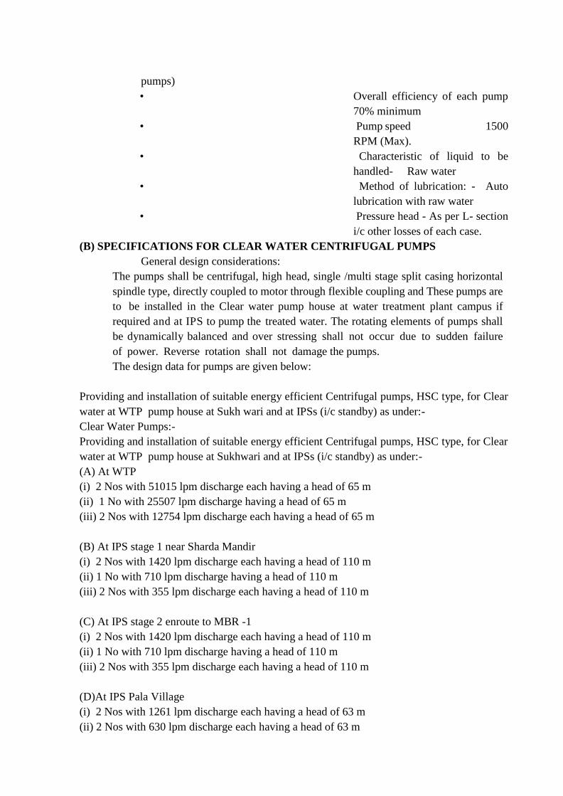
pumps)
• Overall efficiency of each pump
70% minimum
• Pump speed 1500
RPM (Max).
• Characteristic of liquid to be
handled- Raw water
• Method of lubrication: - Auto
lubrication with raw water
• Pressure head - As per L- section
i/c other losses of each case.
(B) SPECIFICATIONS FOR CLEAR WATER CENTRIFUGAL PUMPS
General design considerations:
The pumps shall be centrifugal, high head, single /multi stage split casing horizontal
spindle type, directly coupled to motor through flexible coupling and These pumps are
to be installed in the Clear water pump house at water treatment plant campus if
required and at IPS to pump the treated water. The rotating elements of pumps shall
be dynamically balanced and over stressing shall not occur due to sudden failure
of power. Reverse rotation shall not damage the pumps.
The design data for pumps are given below:
Providing and installation of suitable energy efficient Centrifugal pumps, HSC type, for Clear
water at WTP pump house at Sukh wari and at IPSs (i/c standby) as under:-
Clear Water Pumps:-
Providing and installation of suitable energy efficient Centrifugal pumps, HSC type, for Clear
water at WTP pump house at Sukhwari and at IPSs (i/c standby) as under:-
(A) At WTP
(i) 2 Nos with 51015 lpm discharge each having a head of 65 m
(ii) 1 No with 25507 lpm discharge having a head of 65 m
(iii) 2 Nos with 12754 lpm discharge each having a head of 65 m
(B) At IPS stage 1 near Sharda Mandir
(i) 2 Nos with 1420 lpm discharge each having a head of 110 m
(ii) 1 No with 710 lpm discharge having a head of 110 m
(iii) 2 Nos with 355 lpm discharge each having a head of 110 m
(C) At IPS stage 2 enroute to MBR -1
(i) 2 Nos with 1420 lpm discharge each having a head of 110 m
(ii) 1 No with 710 lpm discharge having a head of 110 m
(iii) 2 Nos with 355 lpm discharge each having a head of 110 m
(D)At IPS Pala Village
(i) 2 Nos with 1261 lpm discharge each having a head of 63 m
(ii) 2 Nos with 630 lpm discharge each having a head of 63 m
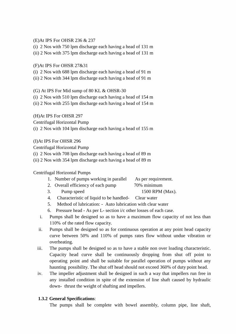
(E)At IPS For OHSR 236 & 237
(i) 2 Nos with 750 lpm discharge each having a head of 131 m
(ii) 2 Nos with 375 lpm discharge each having a head of 131 m
(F)At IPS For OHSR 27&31
(i) 2 Nos with 688 lpm discharge each having a head of 91 m
(ii) 2 Nos with 344 lpm discharge each having a head of 91 m
(G) At IPS For Mid sump of 80 KL & OHSR-30
(i) 2 Nos with 510 lpm discharge each having a head of 154 m
(ii) 2 Nos with 255 lpm discharge each having a head of 154 m
(H)At IPS For OHSR 297
Centrifugal Horizontal Pump
(i) 2 Nos with 104 lpm discharge each having a head of 155 m
(I)At IPS For OHSR 296
Centrifugal Horizontal Pump
(i) 2 Nos with 708 lpm discharge each having a head of 89 m
(ii) 2 Nos with 354 lpm discharge each having a head of 89 m
Centrifugal Horizontal Pumps
1. Number of pumps working in parallel As per requirement.
2. Overall efficiency of each pump 70% minimum
3. Pump speed 1500 RPM (Max).
4. Characteristic of liquid to be handled- Clear water
5. Method of lubrication: - Auto lubrication with clear water
6. Pressure head - As per L- section i/c other losses of each case.
i. Pumps shall be designed so as to have a maximum flow capacity of not less than
110% of the rated flow capacity.
ii. Pumps shall be designed so as for continuous operation at any point head capacity
curve between 50% and 110% of pumps rates flow without undue vibration or
overheating.
iii. The pumps shall be designed so as to have a stable non over loading characteristic.
Capacity head curve shall be continuously dropping from shut off point to
operating point and shall be suitable for parallel operation of pumps without any
haunting possibility. The shut off head should not exceed 360% of duty point head.
iv. The impeller adjustment shall be designed in such a way that impellers run free in
any installed condition in spite of the extension of line shaft caused by hydraulic
down- thrust the weight of shafting and impellers.
1.3.2 General Specifications:
The pumps shall be complete with bowel assembly, column pipe, line shaft,
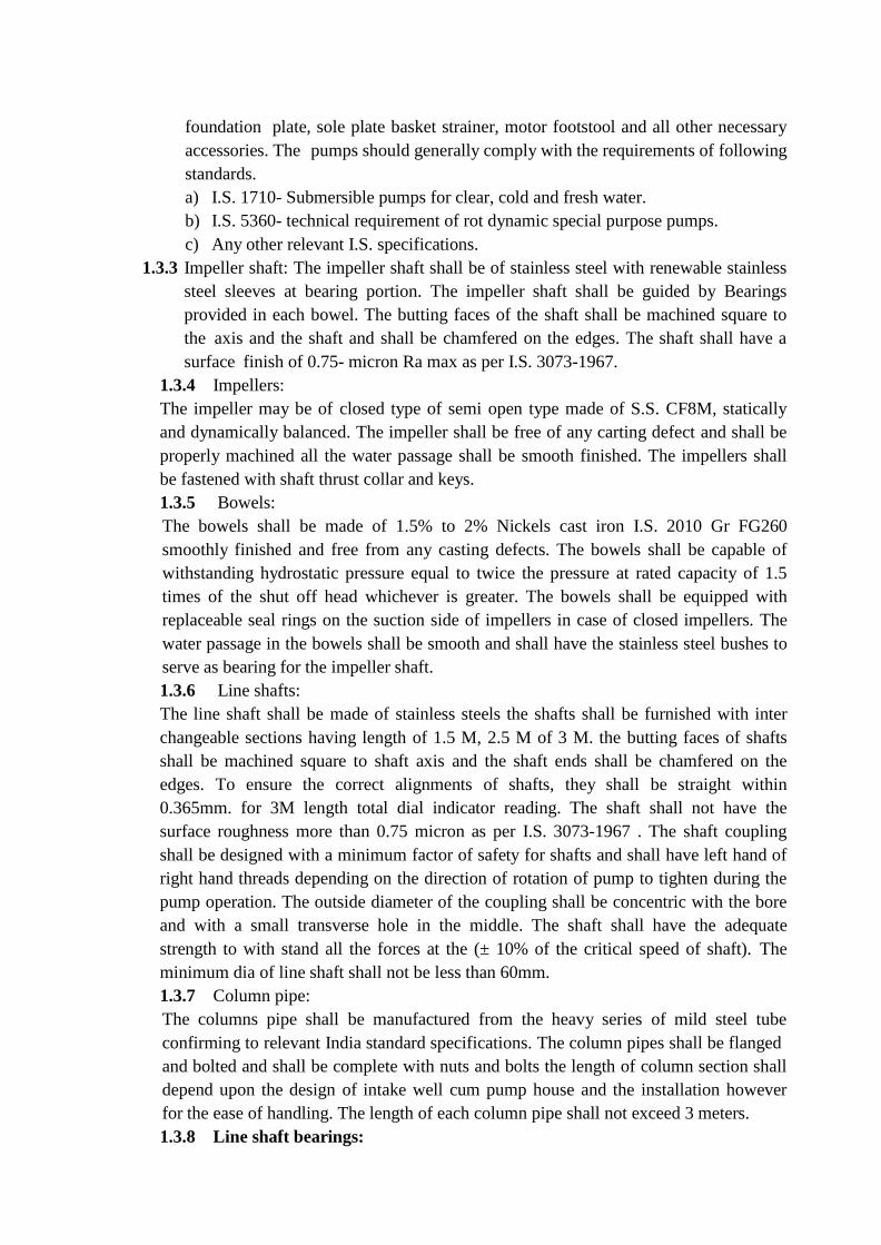
foundation plate, sole plate basket strainer, motor footstool and all other necessary
accessories. The pumps should generally comply with the requirements of following
standards.
a) I.S. 1710- Submersible pumps for clear, cold and fresh water.
b) I.S. 5360- technical requirement of rot dynamic special purpose pumps.
c) Any other relevant I.S. specifications.
1.3.3 Impeller shaft: The impeller shaft shall be of stainless steel with renewable stainless
steel sleeves at bearing portion. The impeller shaft shall be guided by Bearings
provided in each bowel. The butting faces of the shaft shall be machined square to
the axis and the shaft and shall be chamfered on the edges. The shaft shall have a
surface finish of 0.75- micron Ra max as per I.S. 3073-1967.
1.3.4 Impellers:
The impeller may be of closed type of semi open type made of S.S. CF8M, statically
and dynamically balanced. The impeller shall be free of any carting defect and shall be
properly machined all the water passage shall be smooth finished. The impellers shall
be fastened with shaft thrust collar and keys.
1.3.5 Bowels:
The bowels shall be made of 1.5% to 2% Nickels cast iron I.S. 2010 Gr FG260
smoothly finished and free from any casting defects. The bowels shall be capable of
withstanding hydrostatic pressure equal to twice the pressure at rated capacity of 1.5
times of the shut off head whichever is greater. The bowels shall be equipped with
replaceable seal rings on the suction side of impellers in case of closed impellers. The
water passage in the bowels shall be smooth and shall have the stainless steel bushes to
serve as bearing for the impeller shaft.
1.3.6 Line shafts:
The line shaft shall be made of stainless steels the shafts shall be furnished with inter
changeable sections having length of 1.5 M, 2.5 M of 3 M. the butting faces of shafts
shall be machined square to shaft axis and the shaft ends shall be chamfered on the
edges. To ensure the correct alignments of shafts, they shall be straight within
0.365mm. for 3M length total dial indicator reading. The shaft shall not have the
surface roughness more than 0.75 micron as per I.S. 3073-1967 . The shaft coupling
shall be designed with a minimum factor of safety for shafts and shall have left hand of
right hand threads depending on the direction of rotation of pump to tighten during the
pump operation. The outside diameter of the coupling shall be concentric with the bore
and with a small transverse hole in the middle. The shaft shall have the adequate
strength to with stand all the forces at the (± 10% of the critical speed of shaft). The
minimum dia of line shaft shall not be less than 60mm.
1.3.7 Column pipe:
The columns pipe shall be manufactured from the heavy series of mild steel tube
confirming to relevant India standard specifications. The column pipes shall be flanged
and bolted and shall be complete with nuts and bolts the length of column section shall
depend upon the design of intake well cum pump house and the installation however
for the ease of handling. The length of each column pipe shall not exceed 3 meters.
1.3.8 Line shaft bearings:
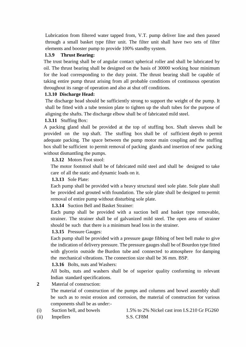
Lubrication from filtered water tapped from, V.T. pump deliver line and then passed
through a small basket type filter unit. The filter unit shall have two sets of filter
elements and booster pump to provide 100% standby system.
1.3.9 Thrust Bearing:
The trust bearing shall be of angular contact spherical roller and shall be lubricated by
oil. The thrust bearing shall be designed on the basis of 30000 working hour minimum
for the load corresponding to the duty point. The thrust bearing shall be capable of
taking entire pump thrust arising from all probable conditions of continuous operation
throughout its range of operation and also at shut off conditions.
1.3.10 Discharge Head:
The discharge head should be sufficiently strong to support the weight of the pump. It
shall be fitted with a tube tension plate to tighten up the shaft tubes for the purpose of
aligning the shafts. The discharge elbow shall be of fabricated mild steel.
1.3.11 Stuffing Box:
A packing gland shall be provided at the top of stuffing box. Shaft sleeves shall be
provided on the top shaft. The stuffing box shall be of sufficient depth to permit
adequate packing. The space between the pump motor main coupling and the stuffing
box shall be sufficient to permit removal of packing glands and insertion of new packing
without dismantling the pumps.
1.3.12 Motors Foot stool:
The motor footstool shall be of fabricated mild steel and shall be designed to take
care of all the static and dynamic loads on it.
1.3.13 Sole Plate:
Each pump shall be provided with a heavy structural steel sole plate. Sole plate shall
be provided and grouted with foundation. The sole plate shall be designed to permit
removal of entire pump without disturbing sole plate.
1.3.14 Suction Bell and Basket Strainer:
Each pump shall be provided with a suction bell and basket type removable,
strainer. The strainer shall be of galvanized mild steel. The open area of strainer
should be such that there is a minimum head loss in the strainer.
1.3.15 Pressure Gauges:
Each pump shall be provided with a pressure gauge fibbing of best bell make to give
the indication of delivery pressure. The pressure gauges shall be of Bourdon type fitted
with glycerin outside the Burdon tube and connected to atmosphere for damping
the mechanical vibrations. The connection size shall be 36 mm. BSP.
1.3.16 Bolts, nuts and Washers:
All bolts, nuts and washers shall be of superior quality conforming to relevant
Indian standard specifications.
2 Material of construction:
The material of construction of the pumps and columns and bowel assembly shall
be such as to resist erosion and corrosion, the material of construction for various
components shall be as under:-
(i) Suction bell, and bowels 1.5% to 2% Nickel cast iron I.S.210 Gr FG260
(ii) Impellers S.S. CF8M
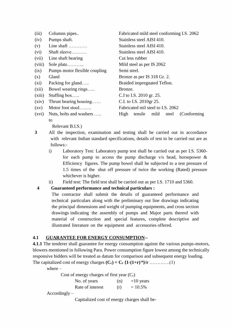
(iii) Columns pipes.. Fabricated mild steel conforming I.S. 2062
(iv) Pumps shaft. Stainless steel AISI 410.
(v) Line shaft ………… Stainless steel AISI 410.
(vi) Shaft sleeve………. Stainless steel AISI 410.
(vii) Line shaft bearing Cut less rubber
(viii) Sole plate……….. Mild steel as per IS 2062
(ix) Pumps motor flexible coupling Semi steel.
(x) Gland Bronze as per IS 318 Gr. 2.
(xi) Packing for gland….. Braided impregnated Teflon.
(xii) Bowel wearing rings….. Bronze.
(xiii) Stuffing box….. C.I to I.S. 2010 gr. 25.
(xiv) Thrust bearing housing…… C.I. to I.S. 2010gr 25.
(xv) Motor foot stool…….. Fabricated mil steel to I.S. 2062
(xvi) Nuts, bolts and washers ….. High tensile mild steel (Conforming
to
Relevant B.I.S.)
3 All the inspection, examination and testing shall be carried out in accordance
with relevant Indian standard specifications, details of test to be carried out are as
follows:-
i) Laboratory Test: Laboratory pump test shall be carried out as per I.S. 5360-
for each pump to access the pump discharge v/s head, horsepower &
Efficiency figures. The pump bowel shall be subjected to a test pressure of
1.5 times of the shut off pressure of twice the working (Rated) pressure
whichever is higher.
ii) Field test: The field test shall be carried out as per I.S. 1710 and 5360.
4 Guaranteed performance and technical particulars :
The contractor shall submit the details of guaranteed performance and
technical particulars along with the preliminary out line drawings indicating
the principal dimensions and weight of pumping equipments, and cross section
drawings indicating the assembly of pumps and Major parts thereof with
material of construction and special features, complete descriptive and
illustrated literature on the equipment and accessories offered.
4.1 GUARANTEE FOR ENERGY CONSUMPTION--
4.1.1 The tenderer shall guarantee for energy consumption against the various pumps-motors,
blowers mentioned in following Para. Power consumption figure lowest among the technically
responsive bidders will be treated as datum for comparison and subsequent energy loading.
The capitalized cost of energy charges (Cc) = Cr {1-(1+r)-n}/r ………….(1)
where –
Cost of energy charges of first year (Cr)
No. of years (n) =10 years
Rate of interest (r) = 10.5%
Accordingly –
Capitalized cost of energy charges shall be-
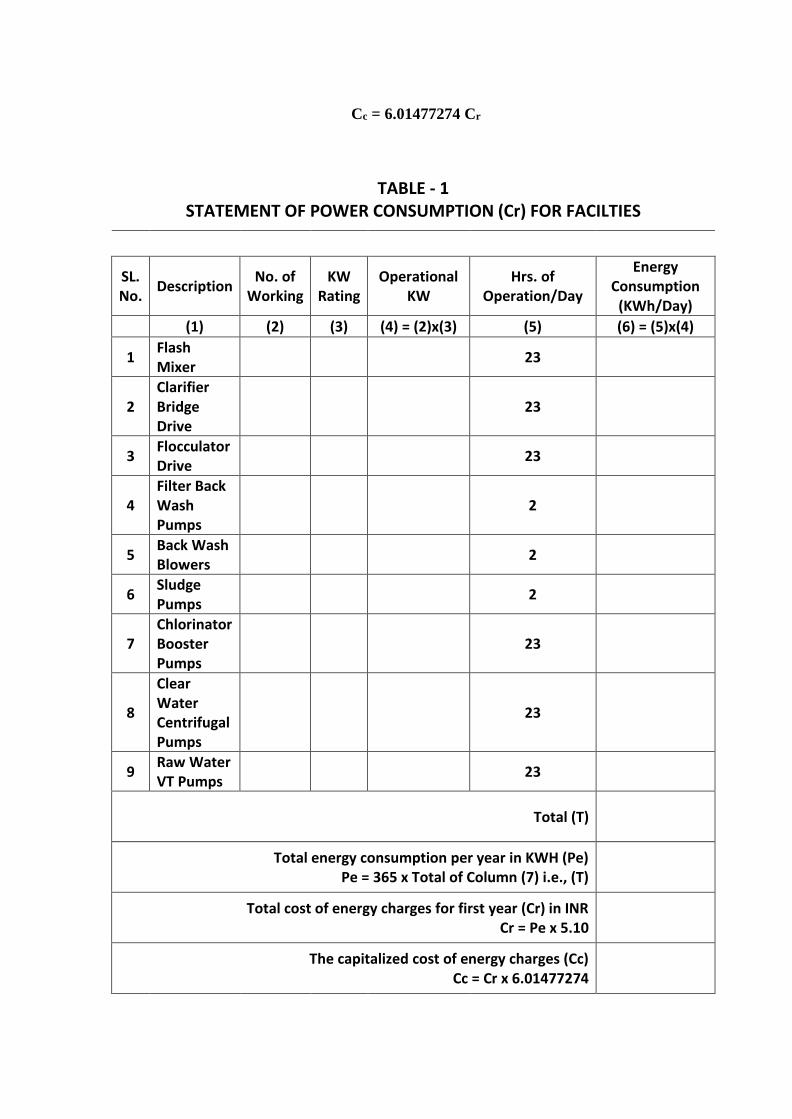
Cc = 6.01477274 Cr
TABLE - 1 STATEMENT OF POWER CONSUMPTION (Cr) FOR FACILTIES
SL. No.
Description No. of
Working KW
Rating Operational
KW Hrs. of
Operation/Day
Energy Consumption
(KWh/Day)
(1) (2) (3) (4) = (2)x(3) (5) (6) = (5)x(4)
1 Flash Mixer
23
2 Clarifier Bridge Drive
23
3 Flocculator Drive
23
4 Filter Back Wash Pumps
2
5 Back Wash Blowers
2
6 Sludge Pumps
2
7 Chlorinator Booster Pumps
23
8
Clear Water Centrifugal Pumps
23
9 Raw Water VT Pumps
23
Total (T)
Total energy consumption per year in KWH (Pe) Pe = 365 x Total of Column (7) i.e., (T)
Total cost of energy charges for first year (Cr) in INR Cr = Pe x 5.10
The capitalized cost of energy charges (Cc) Cc = Cr x 6.01477274
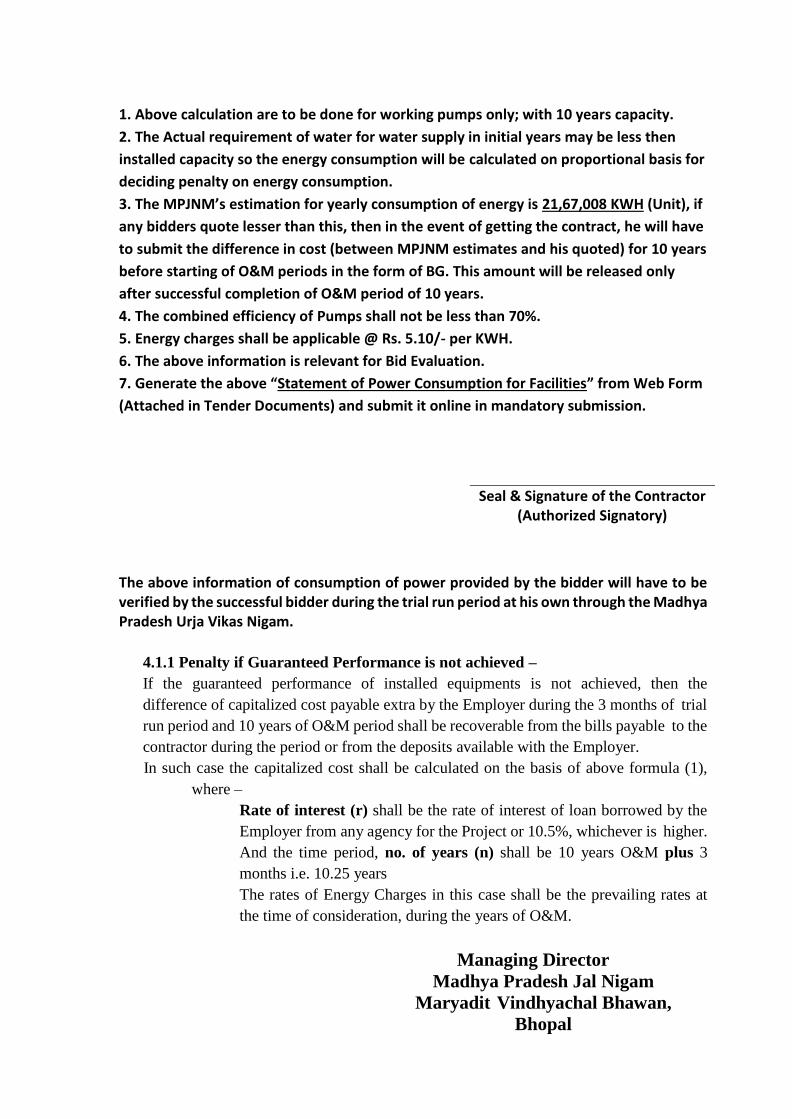
1. Above calculation are to be done for working pumps only; with 10 years capacity.
2. The Actual requirement of water for water supply in initial years may be less then
installed capacity so the energy consumption will be calculated on proportional basis for
deciding penalty on energy consumption.
3. The MPJNM’s estimation for yearly consumption of energy is 21,67,008 KWH (Unit), if
any bidders quote lesser than this, then in the event of getting the contract, he will have
to submit the difference in cost (between MPJNM estimates and his quoted) for 10 years
before starting of O&M periods in the form of BG. This amount will be released only
after successful completion of O&M period of 10 years.
4. The combined efficiency of Pumps shall not be less than 70%.
5. Energy charges shall be applicable @ Rs. 5.10/- per KWH.
6. The above information is relevant for Bid Evaluation.
7. Generate the above “Statement of Power Consumption for Facilities” from Web Form
(Attached in Tender Documents) and submit it online in mandatory submission.
Seal & Signature of the Contractor (Authorized Signatory)
The above information of consumption of power provided by the bidder will have to be verified by the successful bidder during the trial run period at his own through the Madhya Pradesh Urja Vikas Nigam.
4.1.1 Penalty if Guaranteed Performance is not achieved –
If the guaranteed performance of installed equipments is not achieved, then the
difference of capitalized cost payable extra by the Employer during the 3 months of trial
run period and 10 years of O&M period shall be recoverable from the bills payable to the
contractor during the period or from the deposits available with the Employer.
In such case the capitalized cost shall be calculated on the basis of above formula (1),
where –
Rate of interest (r) shall be the rate of interest of loan borrowed by the
Employer from any agency for the Project or 10.5%, whichever is higher.
And the time period, no. of years (n) shall be 10 years O&M plus 3
months i.e. 10.25 years
The rates of Energy Charges in this case shall be the prevailing rates at
the time of consideration, during the years of O&M.
Managing Director
Madhya Pradesh Jal Nigam
Maryadit Vindhyachal Bhawan,
Bhopal

CHAPTER - 1.9
SCOPE OF WORK AND ELECTRIFICATION OF ELECTRIC POWER
LINE CONNECTON AT INTAKE WELL, WTP SITE & IPS
Brief Scope of Work-
Design, Supply, erection and Construction of dedicated 33 KVpower supply to Intake
well cum pump house at the bank of Bansagar dam near village Sukwari (near Markendeya
ghat), for WTP near village Sukwariand various IPSs including construction of suitable
capacity substation and transformers including standby and stretching of power. Campus
lighting and allied internal and external electrical works for the entire project for all
components including all allied civil works etc. complete.
Supply and Erection of 2 X 3.15 MVA+ 1 X 1.6 MVA or suitable capacity transformers ,
Four no.s 11KV out going feeder with Yard, Fencing & other facilities along with a 18 Km
long 33 KV line, 10 km long 11 KV line & 5 Km long LT line, external electrification etc.
complete. 100 % Standby transformers to be provided at each locations..
Liaison with MPPKVVCL for new power supply agreement for getting Electricity
connection, Necessary arrangement for getting MPPKVVCL / Electrical inspectors
clearance and approval for the same or with any agency/department as required, shall be in
Contractors scope. The work shall be done with latest MPPKVVCL's specifications and IS
specifications.
• Supply, installation , testing and commissioning of two pole structure along with lightning
arrestor, disconnector AAAC conductor, clamp and connectors, insulators, hardware, CT-
PT metering set, H.T meter with enclosure etc for taking tapping from incoming overhead
line.
· Supply, installation, testing and commissioning of suitable transformer with Off-circuit
Tap Changer, necessary foundation and earthing.
· Supply, installation, testing and commissioning of the complete electrical distribution
system with Main LV switchboards, process equipment panels etc.
• Supply, installation, testing and commissioning of the complete cabling system with
terminations (scope includes supply of gland, lug, etc.) as per approved drawing.
• Supply, installation, testing and commissioning of the illumination system including new
lighting panels, lighting fixtures, cables, cable terminations, wires, GI conduits, switches,
receptacles, street lighting poles with Junction box and overhang etc. including all the
necessary accessories as per approved lighting layout drawings and technical specification.
• Supply, installation, testing and commissioning of earthing and lightning protection system
with earthing pits and connecting the pits to the earth grid and forming earth grid and
equipment connection to the grid including necessary clamps, nuts, bolts, etc all including
welding, bolting and associated civil works for two pole structure, overhead line, for all
equipments inside and outside plant as per approved layout diagram and technical
specification.
• Civil works associated with the electrical works is also included in the Contractors scope
of works. Preparation of supports and structures for erection of transformers, switchgear,
poles, cable trays and other accessories are included in the scope of works of the
contractor. The work also includes testing at the place of manufacture by a third party as
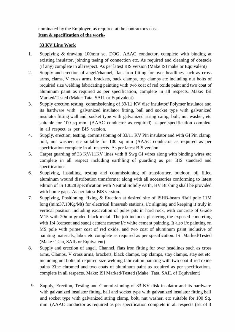
nominated by the Employer, as required at the contractor's cost.
Item & specification of the work-
33 KV Line Work
1. Supplying & drawing 100mm sq. DOG, AAAC conductor, complete with binding at
existing insulator, jointing teeing of connection etc. As required and cleaning of obstacle
(if any) complete in all respect. As per latest BIS version (Make ISI make or Equivalent)
2. Supply and erection of angel/channel, flats iron fitting for over headlines such as cross
arms, clams, V cross arms, brackets, back clamps, top clamps etc including nut bolts of
required size welding fabricating painting with two coat of red oxide paint and two coat of
aluminum paint as required as per specification, complete in all respects. Make: ISI
Marked/Tested (Make: Tata, SAIL or Equivalent)
3. Supply erection testing, commissioning of 33/11 KV disc insulator/ Polymer insulator and
its hardware with galvanized insulator fitting, ball and socket type with galvanized
insulator fitting wall and socket type with galvanized string camp, bolt, nut washer, etc
suitable for 100 sq mm. (AAAC conductor as required) as per specification complete
in all respect as per BIS version.
4. Supply, erection, testing, commissioning of 33/11 KV Pin insulator and with GI Pin clamp,
bolt, nut washer. etc suitable for 100 sq mm (AAAC conductor as required as per
specification complete in all respects. As per latest BIS version.
5. Carpet guarding of 33 KV/11KV lines with 8 Swg GI wires along with binding wires etc
complete in all respect including earthling of guarding as per BIS standard and
specifications.
6. Supplying, installing, testing and commissioning of transformer, outdoor, oil filled
aluminum wound distribution transformer along with all accessories conforming to latest
edition of IS 10028 specification with Neutral Solidly earth, HV Bushing shall be provided
with home gaps, As per latest BIS version.
7. Supplying, Positioning, fixing & Erection at desired site of ISHB-beam /Rail pole 11M
long (min:37.10Kg/Mt) for electrical lines/sub stations, i/c aligning and keeping it truly in
vertical position including excavation of poles pits in hard rock, with concrete of Grade
M15 with 20mm graded black metal. The job includes plastering the exposed concreting
with 1:4 (cement and sand) cement mortar i/c white cement painting. It also i/c painting on
MS pole with primer coat of red oxide, and two coat of aluminum paint inclusive of
painting materials, labor etc complete as required as per specification. ISI Marked/Tested
(Make : Tata, SAIL or Equivalent)
8. Supply and erection of angel. Channel, flats iron fitting for over headlines such as cross
arms, Clamps, V cross arms, brackets, black clamps, top clamps, stay clamps, stay set etc.
including nut bolts of required size welding fabrication painting with two coat if red oxide
paint/ Zinc chromed and two coats of aluminum paint as required as per specifications,
complete in all respects. Make: ISI Marked/Tested (Make: Tata, SAIL of Equivalent)
9. Supply, Erection, Testing and Commissioning of 33 KV disk insulator and its hardware
with galvanized insulator fitting, ball and socket type with galvanized insulator fitting ball
and socket type with galvanized string clamp, bolt, nut washer, etc suitable for 100 Sq.
mm. (AAAC conductor as required as per specification complete in all respects (set of 3
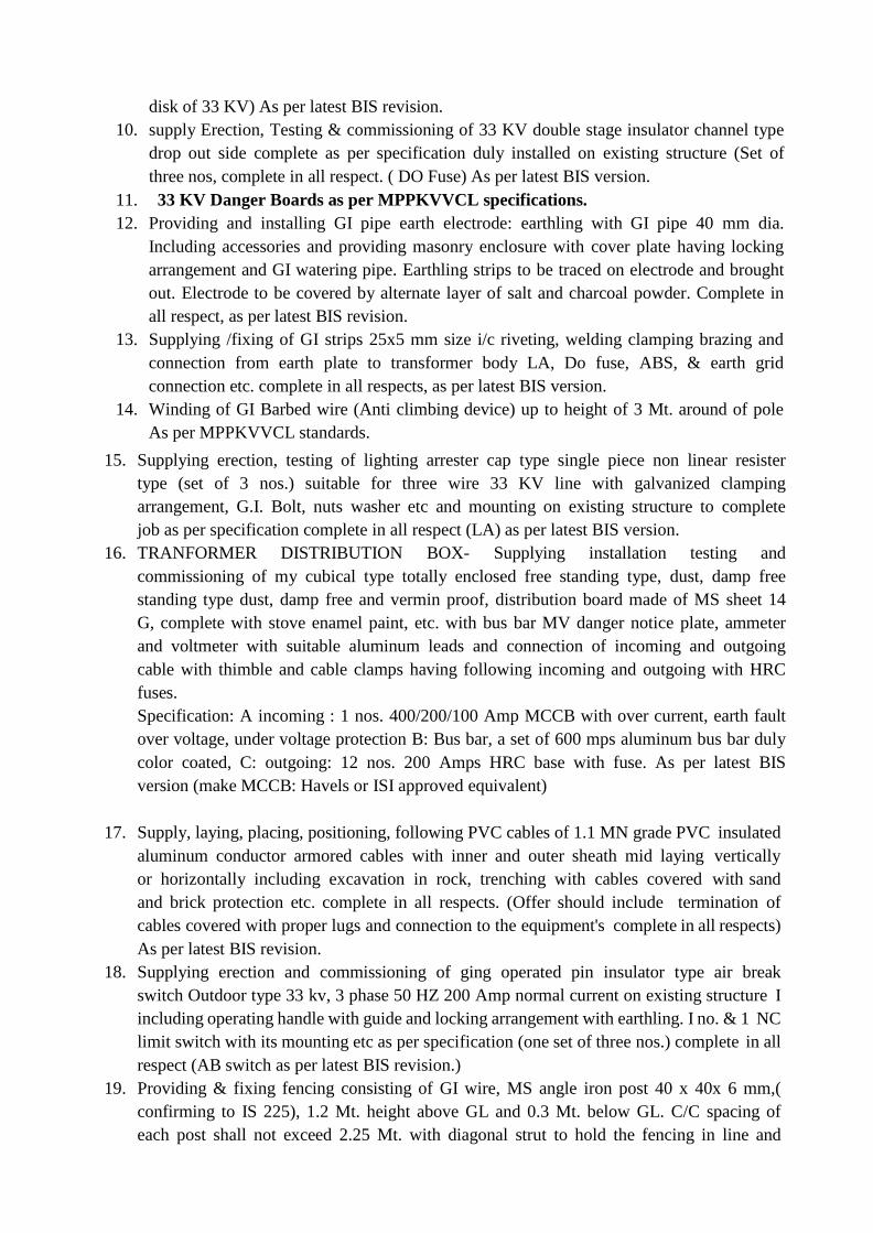
disk of 33 KV) As per latest BIS revision.
10. supply Erection, Testing & commissioning of 33 KV double stage insulator channel type
drop out side complete as per specification duly installed on existing structure (Set of
three nos, complete in all respect. ( DO Fuse) As per latest BIS version.
11. 33 KV Danger Boards as per MPPKVVCL specifications.
12. Providing and installing GI pipe earth electrode: earthling with GI pipe 40 mm dia.
Including accessories and providing masonry enclosure with cover plate having locking
arrangement and GI watering pipe. Earthling strips to be traced on electrode and brought
out. Electrode to be covered by alternate layer of salt and charcoal powder. Complete in
all respect, as per latest BIS revision.
13. Supplying /fixing of GI strips 25x5 mm size i/c riveting, welding clamping brazing and
connection from earth plate to transformer body LA, Do fuse, ABS, & earth grid
connection etc. complete in all respects, as per latest BIS version.
14. Winding of GI Barbed wire (Anti climbing device) up to height of 3 Mt. around of pole
As per MPPKVVCL standards.
15. Supplying erection, testing of lighting arrester cap type single piece non linear resister
type (set of 3 nos.) suitable for three wire 33 KV line with galvanized clamping
arrangement, G.I. Bolt, nuts washer etc and mounting on existing structure to complete
job as per specification complete in all respect (LA) as per latest BIS version.
16. TRANFORMER DISTRIBUTION BOX- Supplying installation testing and
commissioning of my cubical type totally enclosed free standing type, dust, damp free
standing type dust, damp free and vermin proof, distribution board made of MS sheet 14
G, complete with stove enamel paint, etc. with bus bar MV danger notice plate, ammeter
and voltmeter with suitable aluminum leads and connection of incoming and outgoing
cable with thimble and cable clamps having following incoming and outgoing with HRC
fuses.
Specification: A incoming : 1 nos. 400/200/100 Amp MCCB with over current, earth fault
over voltage, under voltage protection B: Bus bar, a set of 600 mps aluminum bus bar duly
color coated, C: outgoing: 12 nos. 200 Amps HRC base with fuse. As per latest BIS
version (make MCCB: Havels or ISI approved equivalent)
17. Supply, laying, placing, positioning, following PVC cables of 1.1 MN grade PVC insulated
aluminum conductor armored cables with inner and outer sheath mid laying vertically
or horizontally including excavation in rock, trenching with cables covered with sand
and brick protection etc. complete in all respects. (Offer should include termination of
cables covered with proper lugs and connection to the equipment's complete in all respects)
As per latest BIS revision.
18. Supplying erection and commissioning of ging operated pin insulator type air break
switch Outdoor type 33 kv, 3 phase 50 HZ 200 Amp normal current on existing structure I
including operating handle with guide and locking arrangement with earthling. I no. & 1 NC
limit switch with its mounting etc as per specification (one set of three nos.) complete in all
respect (AB switch as per latest BIS revision.)
19. Providing & fixing fencing consisting of GI wire, MS angle iron post 40 x 40x 6 mm,(
confirming to IS 225), 1.2 Mt. height above GL and 0.3 Mt. below GL. C/C spacing of
each post shall not exceed 2.25 Mt. with diagonal strut to hold the fencing in line and
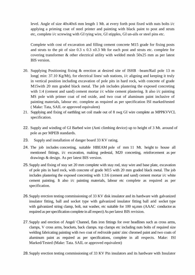
level. Angle of size 40x40x6 mm length 1 Mt. at every forth post fixed with nuts bolts i/c
applying a priming coat of steel printer and painting with black paint to post and struts
etc, complete i/c screwing with GI tying wire, GI stipples, GI un-ails or steel pins etc.
Complete with cost of excavation and filling cement concrete M15 grade for fixing posts
and struts to the pit of size 0.3 x 0.3 x0.3 Mt for each post and struts etc. complete for
covering transformer & other electrical utility with welded mesh 50x25 mm as per latest
BIS version.
20. Supplying Positioning fixing & erection at desired site of ISHB –beam/Rail pole 13 m
long( min: 37.10 Kg/Mt), for electrical lines/ sub stations, i/c aligning and keeping it truly
in vertical position including excavation of pole pits in hard rock, with concrete of grade
M15with 20 mm graded black metal. The job includes plastering the exposed concreting
with 1:4 (cement and sand) cement mortar i/c white cement plastering. It also i/c painting
MS pole with primer coat of red oxide, and two coat of aluminum paint inclusive of
painting materials, labour etc. complete as required as per specification ISI marked/tested
( Make: Tata, SAIL or approved equivalent)
21. Supplying and fixing of earthling set coil made out of 8 swg GI wire complete as MPPKVVCL
specification.
22. Supply and winding of GI Barbed wire (Anti climbing device) up to height of 3 Mt. around of
pole as per MPEB standards.
23. Supply and installation of danger board 33 KV rating.
24. The job includes concreting, suitable HBEAM pole of mm 11 Mt. height to house all
mentioned fittings, i/c excavation, making pedestal, M20 concreting, reinforcement as per
drawings & design. As per latest BIS version.
25. Supply and fixing of stay set 20 mm complete with stay rod, stay wire and base plate, excavation
of pole pits in hard rock, with concrete of grade M15 with 20 mm graded black metal. The job
includes plastering the exposed concreting with 1:3:6 (cement and sand) cement mortar i/c white
cement painting. It also i/c painting materials, labour etc complete as required as per
specification.
26. Supply erection testing commissioning of 33 KV disk insulator and its hardware with galvanized
insulator fitting, ball and socket type with galvanized insulator fitting ball arid socket type
with galvanized string clamp, bolt, nut washer, etc suitable for 100 sq.mm (AAAC conductor as
required as per specification complete in all respect) As per latest BIS revision.
27. Supply and erection of Angel/ Channel, flats iron fittings for over headlines such as cross arms,
clamps, V cross arms, brackets, back clamps. top clamps etc including nuts bolts of required size
welding fabricating painting with two coat of red/oxide paint/ zinc chromed paint and two coats of
aluminum paint as required as per specifications, complete in all respects. Make: ISI
Marked/Tested (Make: Tata. SAIL or approved equivalent)
28. Supply erection testing commissioning of 33 KV Pin insulators and its hardware with Insulator
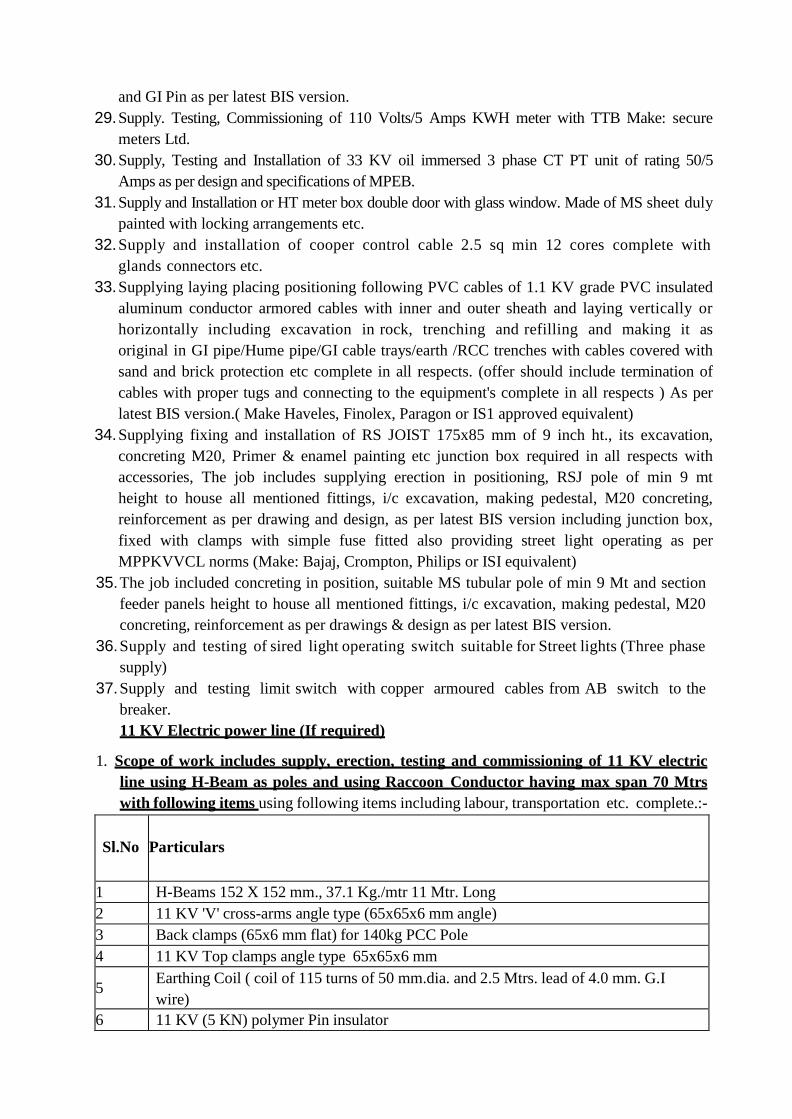
and GI Pin as per latest BIS version.
29. Supply. Testing, Commissioning of 110 Volts/5 Amps KWH meter with TTB Make: secure
meters Ltd.
30. Supply, Testing and Installation of 33 KV oil immersed 3 phase CT PT unit of rating 50/5
Amps as per design and specifications of MPEB.
31. Supply and Installation or HT meter box double door with glass window. Made of MS sheet duly
painted with locking arrangements etc.
32. Supply and installation of cooper control cable 2.5 sq min 12 cores complete with
glands connectors etc.
33. Supplying laying placing positioning following PVC cables of 1.1 KV grade PVC insulated
aluminum conductor armored cables with inner and outer sheath and laying vertically or
horizontally including excavation in rock, trenching and refilling and making it as
original in GI pipe/Hume pipe/GI cable trays/earth /RCC trenches with cables covered with
sand and brick protection etc complete in all respects. (offer should include termination of
cables with proper tugs and connecting to the equipment's complete in all respects ) As per
latest BIS version.( Make Haveles, Finolex, Paragon or IS1 approved equivalent)
34. Supplying fixing and installation of RS JOIST 175x85 mm of 9 inch ht., its excavation,
concreting M20, Primer & enamel painting etc junction box required in all respects with
accessories, The job includes supplying erection in positioning, RSJ pole of min 9 mt
height to house all mentioned fittings, i/c excavation, making pedestal, M20 concreting,
reinforcement as per drawing and design, as per latest BIS version including junction box,
fixed with clamps with simple fuse fitted also providing street light operating as per
MPPKVVCL norms (Make: Bajaj, Crompton, Philips or ISI equivalent)
35. The job included concreting in position, suitable MS tubular pole of min 9 Mt and section
feeder panels height to house all mentioned fittings, i/c excavation, making pedestal, M20
concreting, reinforcement as per drawings & design as per latest BIS version.
36. Supply and testing of sired light operating switch suitable for Street lights (Three phase
supply)
37. Supply and testing limit switch with copper armoured cables from AB switch to the
breaker.
11 KV Electric power line (If required)
1. Scope of work includes supply, erection, testing and commissioning of 11 KV electric
line using H-Beam as poles and using Raccoon Conductor having max span 70 Mtrs
with following items using following items including labour, transportation etc. complete.:-
Sl.No
Particulars
1 H-Beams 152 X 152 mm., 37.1 Kg./mtr 11 Mtr. Long
2 11 KV 'V' cross-arms angle type (65x65x6 mm angle)
3 Back clamps (65x6 mm flat) for 140kg PCC Pole
4 11 KV Top clamps angle type 65x65x6 mm
5 Earthing Coil ( coil of 115 turns of 50 mm.dia. and 2.5 Mtrs. lead of 4.0 mm. G.I
wire)
6 11 KV (5 KN) polymer Pin insulator
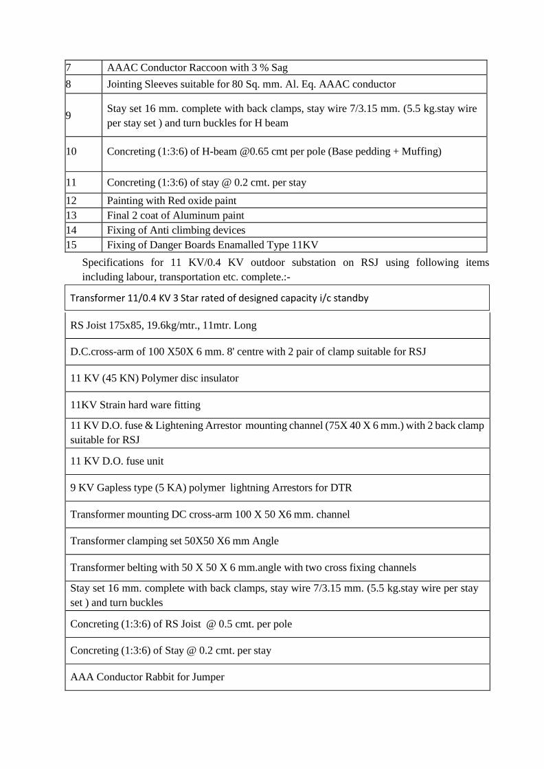
7 AAAC Conductor Raccoon with 3 % Sag
8 Jointing Sleeves suitable for 80 Sq. mm. Al. Eq. AAAC conductor
9 Stay set 16 mm. complete with back clamps, stay wire 7/3.15 mm. (5.5 kg.stay wire
per stay set ) and turn buckles for H beam
10 Concreting (1:3:6) of H-beam @0.65 cmt per pole (Base pedding + Muffing)
11 Concreting (1:3:6) of stay @ 0.2 cmt. per stay
12 Painting with Red oxide paint
13 Final 2 coat of Aluminum paint
14 Fixing of Anti climbing devices
15 Fixing of Danger Boards Enamalled Type 11KV
Specifications for 11 KV/0.4 KV outdoor substation on RSJ using following items
including labour, transportation etc. complete.:-
RS Joist 175x85, 19.6kg/mtr., 11mtr. Long
D.C.cross-arm of 100 X50X 6 mm. 8' centre with 2 pair of clamp suitable for RSJ
11 KV (45 KN) Polymer disc insulator
11KV Strain hard ware fitting
11 KV D.O. fuse & Lightening Arrestor mounting channel (75X 40 X 6 mm.) with 2 back clamp
suitable for RSJ
11 KV D.O. fuse unit
9 KV Gapless type (5 KA) polymer lightning Arrestors for DTR
Transformer mounting DC cross-arm 100 X 50 X6 mm. channel
Transformer clamping set 50X50 X6 mm Angle
Transformer belting with 50 X 50 X 6 mm.angle with two cross fixing channels
Stay set 16 mm. complete with back clamps, stay wire 7/3.15 mm. (5.5 kg.stay wire per stay
set ) and turn buckles
Concreting (1:3:6) of RS Joist @ 0.5 cmt. per pole
Concreting (1:3:6) of Stay @ 0.2 cmt. per stay
AAA Conductor Rabbit for Jumper
Transformer 11/0.4 KV 3 Star rated of designed capacity i/c standby
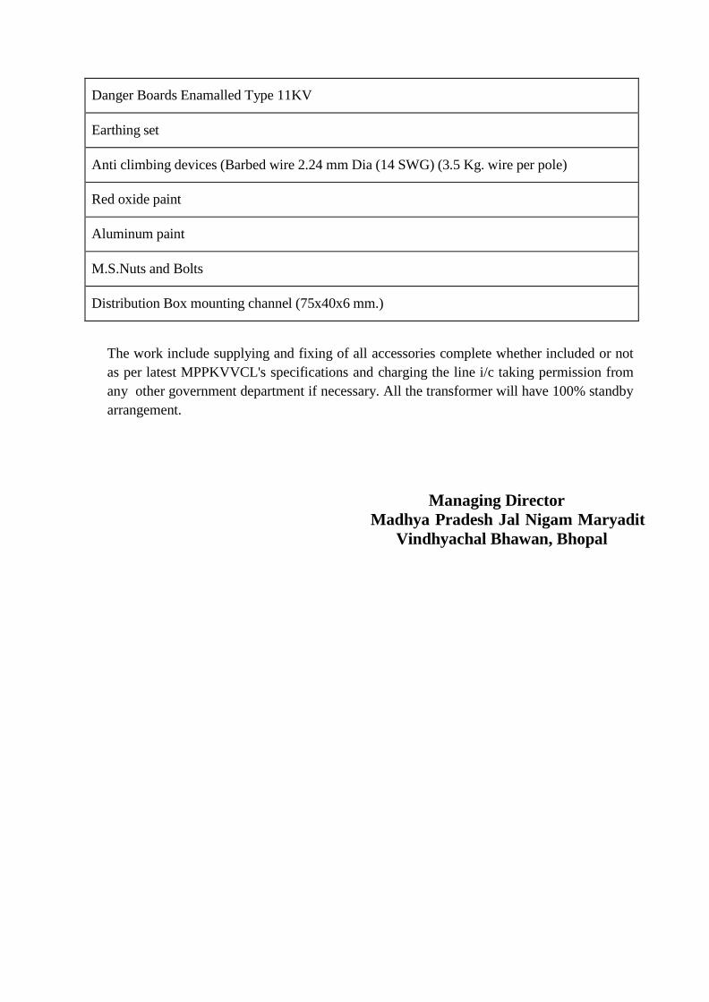
Danger Boards Enamalled Type 11KV
Earthing set
Anti climbing devices (Barbed wire 2.24 mm Dia (14 SWG) (3.5 Kg. wire per pole)
Red oxide paint
Aluminum paint
M.S.Nuts and Bolts
Distribution Box mounting channel (75x40x6 mm.)
The work include supplying and fixing of all accessories complete whether included or not
as per latest MPPKVVCL's specifications and charging the line i/c taking permission from
any other government department if necessary. All the transformer will have 100% standby
arrangement.
Managing Director
Madhya Pradesh Jal Nigam Maryadit
Vindhyachal Bhawan, Bhopal
CHAPTER – 1.10
BRIEF SPECIFICATIONS FOR APPROACH ROAD, BOUNDARY WALL
AND STAFF QUARTERS (i) The specifications of WBM and overlaying bituminous layer shall be as detailed below:-
a) Construction of Embankment/Subgrade/ earth shoulders, as per clause 305 & its sub-
clauses, Where required but with approved materials/soil like morrum CBR value not less
than 7% i/c all lead & lifts i/c excavation, cost of watering, compaction and maintenance
of surface during construction to ensure shedding & preventing ponding of water (clause
305.3.6) shaping & dressing (clause 305.3.7), finishing etc. complete but excluding
scarifying existing granular/bituminous road surface vide clause 305.6.
b) Granular Sub-Base with Coarse Graded Material ( Table:- 400- 2) (Construction of granular
sub-base by providing coarse graded material, spreading in uniform layers with motor
grader on prepared surface, mixing by mix in place method with rotator at OMC, and
compacting with vibratory roller to achieve the desired density, complete as per clause
401)
(iii) for grading-III Material
c) Providing, laying, spreading and compacting stone aggregates of specific sizes to water
bound macadam specification including spreading in uniform thickness, hand packing,
rolling with vibratory roller 8-10 tonnes in stages to proper grade and camber, applying
and brooming requisite type of screening/ binding Materials to fill up the interstices of
coarse aggregate, watering and compacting to the required density.)
By Manual Means i) Grading- I (a) Using Screening Type-A (13.2mm Agg.)
d) Providing, laying, spreading and compacting stone aggregates of specific sizes to water
bound macadam specification including spreading in uniform thickness, hand packing,
rolling with vibratory roller 8-10 tonnes in stages to proper grade and camber, applying
and brooming requisite type of screening/ binding Materials to fill up the interstices of
coarse aggregate, watering and compacting to the required density.
By Manual Means i) Grading- II (a) Using Screening Type-A (13.2mm Agg.)
e) Providing, laying, spreading and compacting stone aggregates of specific sizes to water
bound macadam specification including spreading in uniform thickness, hand packing,
rolling with vibratory roller 8-10 tonnes in stages to proper grade and camber, applying
and brooming requisite type of screening/ binding Materials to fill up the interstices of
coarse aggregate, watering and compacting to the required density.)
By Manual Means (ii) Grading- III (a) Using Screening Type-B (11.2mm Agg.)
f) Providing and applying primer coat with bitumen emulsion on prepared surface of granular Base including clearing of road surface and spraying primer at the rate of 0.60 kg/sqm
using mechanical means.
g) Providing and applying tack coat with bitumen emulsion using emulsion pressure
distributor on the prepared bituminous/granular surface cleaned with mechanical broom
and as per relevant clauses of section-503.
(ii) @ 0.30 kg per sqm (dry & hungry bituminous surfaces/granular surfaces treated with
primer)
h) Open - Graded Premix Surfacing (Providing, laying and rolling of open - graded premix
surfacing of 20 mm thickness composed of 13.2 mm to 5.6 mm aggregates either using
penetration grade bitumen or cut-back or emulsion to required line, grade and level to
serve as wearing course on a previously prepared base, including mixing in a suitable
plant, laying and rolling with a smooth wheeled roller 8-10 tonne capacity, finished to
required level and grades.)
(ii) Case - II: Open-Graded Premix
i) Surfacing using cationic Bitumen Emulsion Seal Coat (Providing and laying seal coat
sealing the voids in a bituminous surface laid to the specified levels, grade and cross
fall using Type A and B seal coats)
(i) Case - I : Type A
j) Construction of unlined surface drains of average cross sectional area 0.40 sqm in soil to
specified lines, grades, levels and dimensions to the requirement of clause 301 and
309. Excavated material to be used in embankment within a lead of 50 meters.
k) “Laying RCC Pipe NP4 / prestrssed concrete pipe on first class bedding in single row for
cross drainage purposes .
Providing and Laying Reinforced cement concrete pipe NP4 / prestressed concrete
pipe 1000 mm dia. for culverts on first class bedding of granular material (cost of bedding
included) in single row including fixing collar with cement mortar 1:2 but excluding
excavation, protection works, backfilling, concrete and masonry works in head walls and
parapets .
Note : 1. Clauses and tables mentioned in specifications above refer to MORTH
specifications.
2. Excavation, disposal of surplus earth, construction of shoulders with
approved material, Plain Cement Concrete for drains and other required works which will
facilitate full functionality shall also form part of the work.
3. Until and unless specified otherwise in this document the road width shall
be 5.5 m with 1 m shoulder on either side.
Specifications for Boundary/Compound wall
a) Excavation for foundation and footing as required including refilling and disposal
at the designated place.
b) Type of foundation shall be as per approved drawing.
c) Plain cement concrete used for foundation shall be minimum of M15 grade
d) RCC used for plinth beam foundation and columns shall be of M 20 grade.
e) Brick work with well burnt chimney bricks having crushing strength not less than 25
kg/cm2 and water absorption not more than 20% using 1:4 cement mortar.
f) Internal and external plastering shall be 12 mm thick using 1:3 cement mortar.
g) Finishing walls with Acrylic smooth exterior paint of required shade (two or more
coat applied @ 1.67 liters /10 sqm over and including base coat of water proofing
cement paint applied @2.0 kg/10sqm.
h) Providing and fixing of gate built with structural steel as per approved drawing and
specifications at every location.
i) The height of boundary wall above ground level shall be minimum 2 m.
Office Building, Administrative Building and Staff Quarters
The following office building, administrative building and staff quarters are to be
designed and constructed at Intake /WTP campus and at Maihar town as decided and approved
by Jal Nigam officials-
1. Office Building at Maihar Town with minimum plinth area 225 .00 Sqm,
2. Admin block at WTP with minimum plinth area 225 .00 Sqm
3. Store Building 75.00 Sqm at WTP
4. F – Type Quarter with minimum plinth area 93.0 Sqm each - 2 No.
5. G - Type Quarter with minimum plinth area 65.0 Sqm each - 2 Nos.
6. H - Type Quarter with minimum plinth area 46.5 Sqm each- 2 Nos.
7. I - Type Quarter with minimum plinth area 32.5 Sqm each - 12 Nos.
The general specifications of the staff quarters are as under -
All the staff quarters/Office shall be RCC framed brick masonry structures. The columns,
Beams, Lintels, Chhajjas, Slabs shall be constructed in RCC M - 25 grade of concrete and walls
shall be constructed in brick masonry with 1:6 cement mortar duly plastered with 1:5 cement
mortar. The specifications of all the materials have already given earlier, however brief
description of different components of quarters are as under -
1. Foundation - The foundation shall be of RCC footing or raft as per safe bearing capacity
of foundation strata.
2. Plinth - The minimum height of plinth shall be 0.60 m above from highest nearby ground
level. The plinth shall be filled with hard moorum or stone crusher dust duly compacted.
An RCC floor slab shall be laid at plinth level with minimum reinforcement. The
minimum thickness of slab shall not be less than 0.15 m.
3. Flooring - Kota stone flooring shall be done in I to H type of quarters and in G and F type
of quarters flooring of Vitrified tiles shall be provided.
4. Walls - The brick masonry walls shall be constructed as per specifications given earlier.
The minimum thickness of the outer walls shall be 0.20 m and partition wall may be of
half brick wall..
5. Doors - All the door frames shall be constructed by sal/malesia sal wood and panels shall
be constructed by flush door panels except outer doors. The outer door shutters shall be
constructed by teak wood panels. All the doors have one additional panel having mosquito
net in 3 track system. The doors of wash rooms may be constructed in aluminum frame
with PVC shutters. All the doors shall also be provided with interlock arrangement.
6. Windows - 30 % of floor area shall be provided for door and windows. All the windows
shall be constructed of aluminum framed with 4 mm thick glass panes and mosquito net.
MS grill shall also be provided in each window.
7. Electrification - Concealed electric fitting shall be done as per standard IE rules. Each
room shall be provided with sufficient number of points for lights, fans, power points,
sockets and etc. Separate line for inverter shall also be laid. All fixtures like energy
efficient tube lights- LED, Night lamps, Fans, Exhaust Fans, Geyser etc as required of
ISI mark and of standard make shall be provided.
8. Water Supply – Concealed water supply fitting shall be provided. GI class medium/CPVC
pipes can be used. A water storage tank of minimum 2000 lts capacity shall also be
constructed over roof. Sufficient number of points for fresh as well as for stored water
shall be provided for Kitchen, Dining room, Toilet, Court yard and etc. Provision for
geyser connection, mixers shall also be provided.
9. Sanitary – Provision of attached toilets for bed rooms shall be provided. A common toilet
shall also be provided. Glazed tiles shall be provided on inner walls of the toilet upto full
height. Toilet block should have European/Indian type WC with flushing arrangement,
shower, fresh and stored water outlets, Geyser point, and wash basin. A septic tank of
sufficient capacity shall be constructed. Internal drainage lines may be of UPVC and
external line may be of UPVC/RCC and should be laid upto local drain/sewer. Roof water
harvesting arrangement shall also be provided.
10. General - All the bed rooms will have the facility of wooden almirah, Dining room should
be provided with wash basin, Kitchen should have the facilities of Kitchen stand, Sink,
sufficient almirah/cupboard, exhaust fan and etc. Preferably all the bed rooms should
have attached toilet unit with European seats. All the fixtures shall be of standard make
and shall be ISI mark as approved by Jal Nigam Officials. H and I type quarter may be
duplex type and G & H type may be constructed as row houses and F type should be
constructed separately.
11.0 Specifications for Administrative Building at WTP and Office Building at Maihar:-
The Administrative Building and office building should be fully furnished and air
conditioned with office equipment and accessories necessary to discharge the official
functions like furniture , telecommunication, conferencing and storage and should have
sufficient number of rooms to accommodate 5 officers and 12 supporting staff. The
flooring of the office building shall be of Vitrified tiles. Minimum two toilet blocks one
for ladies and another for gents for supporting staff and attach toilet with room for
officials.
Roof water harvesting arrangement for office building/quarters shall also be provided.
The office and residential premises would be covered with boundary wall and entrance
gates giving a pleasant environment of a campus fully lighted externally and internally
with all safety supported with audio visual watch and ward and internal communication.
The Administrative/ Office Building/ Staff quarters should have covered parking sheds
with sufficient parking facilities commensurate with requirement as estimated during
time of construction by MPJNM.
Managing Director
Madhya Pradesh Jal NigamMaryadit
Vindhyachal Bhawan, Bhopal
CHAPTER – 1.11
Automation at Intake, WTP, IPS, MBR's, and ESR's
(i) General
The automatic process control of the plant shall typically be based on the use
of a number of programmable logic controllers (PLCs). These shall be located
within control panels.
The supervisory monitoring of the entire treatment plant shall be implemented
by a site system provided in the administrative building control room by the
contractor. The contractor shall also provide a static mimic panel of minimum
2m x 1m size within the administration building control room with the main
processes engraved on mosaic tales and with edgewise instruments displaying
all main flows and levels (local raw water and clear water tank levels, residual
values, number of filters in service etc.), together with indicator lamps for
combined faults for each process/area of the works. It is intended that the
operator will investigate each local area for the individual faults displayed.
The control system shall be provided and located in the administrative building
at the water treatment works. The SCADA system shall comprise the
following;
An industrial grade latest personnel computer (PC). This shall be provided to
the latest industry standard conducive to the efficient and effective operation of
the selected SCADA software package. It shall be provided with latest drives.
The fixed drive shall be sized to permit the operation of the system and the
storage of the following ;
❖ In excess of 2000 historic alarms data;
❖ Not less than 7 months archive data.
❖ Plus not less than 50% spare capacity.
❖ One latest industry standard 20" colour monitor;
❖ Mouse;
❖ 132 column alarm/event latest dot matrix printer with fan fold paper
attachment;
Colour inkjet screen dup printer with multiple single sheet feeder (the printer
shall be suitable for use at the local SCADA system);
Metal computer desk with vinyl work surface and one pedestal draw unit and
one cupboard unit, the desk shall accommodate the PC and alarm/event printer
and permit two operators to sit side by side. The desk shall be purpose built,
attractive, durable and ergonomic and it shall be sized to have not less than 50%
spare work surface when accommodating the PC and printer. The desk shall
incorporate an integral power distribution system to supply equipment mounted
on desk;
full height two door metal storage cupboard with three shelves;
2 Nos upholstered swivel chairs;
Printer trolley/s to accommodate the report and screen dump printer.
The Contractor shall provide proprietary SCADA software for the central
SCADA systems. The SCADA software shall be windows based. It shall have
a proven track record for similar applications in the water industry and shall be
supported within India.
The SCADA system shall be the same as that used for the local SCADA
systems. The software package selected shall provide facilities for the provision
of the following :
❖ Colour graphic screen representation of each plant area including system
overviews;
❖ Alarm annunciation and historic logging of alarms;'
❖ Historic event logging.
❖ Real time and historic trending of analogue variables;
❖ Preparation of simple reports;
Archiving of system variables for retrieval on to third party machines operating
industry standard spreadsheet and database software and onto machines using
the SCADA software, which shall permit trend graphs of the archived data to
be recreated.
The Contractor shall configure the SCADA system to provide facilities to:
display status, values and totals in a graphical and tabular format (see note 1);
annunciate alarms including details of the time the alarm occurred (see note 3);
provide facilities for the operator to :
acknowledge alarms
view a journal of unacknowledged alarms;
view a journal of the last 200 alarms acknowledged and unacknowledged;
carry out real time (see note 4) and historic trending of analogue values (see
note 3).
carry out data archiving of all analogue values to optical disk (see note 5);
prepare daily, weekly, monthly and annual reports (see note 6).
The SCADA system shall be configured by the Contractor to carry out any
additional requirements needed to assist in the effective and efficient operation
and monitoring of the water transmission system.
NOTES :
1. Graphic screens shall be provided as follows :
overview of the treatment works;
active colour graphic flow diagrams for each process and section of the works
sufficient to convey to the operations staff and management the status of the
plant including the power supply and control system at all times;
2. A comprehensive screen navigation system shall be provided giving access to
all screens via a system of menus and short cuts (i.e. it shall be possible to
follow from one screen to another by clicking the mouse cursor on screen
'hotspots' to effect the move from one screen to another and back against).
3. The software chosen shall have a comprehensive alarm handling capability
with the ability to annunciate, acknowledge, sort and maintain a historic record
of current and past alarms including details of when the alarm occurred, when
it was acknowledged and when it returned to normal.
4. The system shall be capable of storing real time data for one day and historic
data for 7 months.
5. The sample rates for archiving shall be the same as for trending. The archives
shall be stored in daily files. The system shall provide separate storage capacity
to store archives for one year. A warning alarm shall be provided to the operator
to advise that archiving to disk should take place or archived data will be
overwritten.
It shall be possible to;
Reintroduced the data derived from archiving and view the archived data
facility;
Display the data using industry standard spread sheet or database software in
tabular format on a third party machine;
6. The SCADA system shall manipulate the data it receives in order to prepare
reports in order to provide the Employer with a schedule of throughput and
power consumption for the period concerned. The reports shall be generated on
demand and automatically as required.
The Contractor shall monitor summary status of all the treatment works as
follows:
water level raw water and clear water reservoirs;
❖ process flows and totalized quantities;
❖ water quality values
❖ status of each process;
❖ reservoir high high and low low level alarms;
❖ power outage present;
❖ power consumed per day;

❖ individual power consumption;
❖ power factor;
❖ water treatended in the last complete 24 hour period (midnight to
midnight, time selectable);
❖ total power outage house per day.
The SCADA system and its ancillary equipment shall be powered via an
uninterruptible power supply with a hold up time at full output of the UPS for
60 minutes. The full output of the UPS shall correspond to the maximum
imposed load plus 20%.
The scope of work includes providing power backup in the form of solar panel
and battery (of atleast 100 watts capacity) at MBR/OHSR/OHT for operating
flow meters uninterruptedly and providing illumination in the campus.
Managing Director
Madhya Pradesh Jal NigamMaryadit
Vindhyachal Bhawan, Bhopal
CHAPTER – 1.12
Specifications for tunnel Specifications for tunnel work
The work specified under this contract shall include preparatory and general work, design, material
and work of any kind necessary for the due and satisfactory construction, completion and
maintenance of the works to the intent and meaning of applicable IS specifications and any further
drawing and orders that may be issued by the Engineer from time to time, compliance by the
contactor with all conditions of contract, whether specially mentioned or not in this Specification ;
all materials apparatus, plan, machinery, tools, fuel, water strutting timbering and tackle of every
description transport offices , store , workshop, staff, labour and the provision of proper and
sufficient protective works, temporary fencing, lighting, and watching required for the safety of the
public and the protection of the work and adjoining land ; the provision and maintenance of first aid
equipment, sanitary accommodation for the staff and workmen; all insurances, the payment of
wages, salaries, fees, royalties, duties or other charges; obtaining permission and clearances for all
necessary works from the competent authority; the clearance of rubbish, reinstatement and clearing
up and leaving the site in good condition.
The tunnel should be of "D" shape having a finished dimension of 3.00 m and length of 1.50
km. To expedite the progress it is proposed to provide TWO working face during construction for
allowing lowering and removing excavation muck and equipment, suitable approach road will have
to be constructed to reach the location as well as for disposal of excavated materials to suitable
identified location by contractor at its own.
The contractor is required to get the geotechnical investigations required to be done from the
Geological Survey of India, GOI and the report, design and drawings built on the basis of these
investigations should be get vetted from any IIT/NIT. The contractor will have to carry out detailed
subsurface Geo Technical investigation by taking bore holes are every 500.00 m spacing along the
alignment of the tunnel or as desired by the Geologist , G.S.I.. The holes will be drilled upto a depth
of 5.00 m below the invert-level of the tunnel. The contractor will have to submit detailed
engineering Geo Technical and rock mechanics analysis report based on bore hole data and shall
prepare Geo Technical L-Section along the tunnel alignment that will decide support system. The
contractor will then prepare detailed design and after getting them vetted from any IIT/NIT, submit
for approval of the competent authorities before commencement of actual work of contraction.
The brief scope of work includes but is not limited to -
• The tentative starting co-ordinates of the tunnel are ‘ LAT 24 deg 13 min 20.21 sec
LONG 80 deg 59 min 54.33 sec’ and the end co-ordinates are ‘LAT 24 deg 14 min
05.22 sec LONG 80 deg 59 min 35.72 sec. The tunnel is required to convey clear
water and the location of hill through which the tunnel will be excavated lies between
Bansagar dam and Amarpatan near village Mankahari.
• Driving of tunnel by tunnelling methods including excavation with supports in all
types of soil/ rock strata requiring supports including cost of supports, blasting, all
materials, machinery, labour, ventilation, lighting, drainage, dewatering, scaling
excavated surface, removing and hauling excavated muck outside tunnel upto
specified dump area and all other ancillary operations etc, complete with all
underground and ground leads and lifts.
• Dewatering and pumping of the working area in the tunnel including all connected
operations of laying of pipeline, removal of all seepage and other operations required
for maintaining cleanliness for construction work. etc. complete.
• Providing 25 mm thick guniting /shotcreting to sides and arch of tunnel in M-25
proportion by weight including cost of all materials, machinery, labour, ventilation,
lighting, drainage and all other ancillary operations etc. complete.
• Providing and fixing 25 mm dia. steel rock bolts with one end provided with
mechanical/ wedge type anchorage and other end provided with threads for fixing
washers and nuts including cost of all materials, machinery, labour, ventilation,
lighting, drainage, drilling 35-40 mm dia. holes, providing 150 mm long 20 mm thick
steel tapered wedge, providing 10 mm thick and 200x200 mm size plate washer and
nuts, driving bolt, fixing washers and nuts, tightening bolt by torque wrench after
hardness of the cement grout and all other ancillary operations etc. complete.
• Providing and fixing 25 mm diameter steel rock bolts with resin bond cement capsule
anchorage including cost of all materials, machinery, labour, ventilation, lighting,
drainage, drilling 35-40 mm dia. holes, threading one end of bolt for fixing nuts,
inserting grout capsule, driving bolt, fixing 10 mm thick and 200x200 mm size plate
washer and nuts, tightening the nuts by torque wrench after hardening of cement
grout and all other ancillary operations etc. complete.
• Providing fabrication and fixing in position permanent structural steel supports as
per details including cost of all materials, machinery, labour, ventilation, lighting,
drainage, drainage cutting, bending, welding, grinding and all other ancillary
operations etc. complete.
• Providing and constructing un-coursed rubble stone masonry with approved stones
from tunnel excavated muck in CM 1:6 proportion by volume for backfilling over
cuts/ slips on tunnel sides due to geological faults etc., including cost of all materials,
machinery, labour, ventilation, lighting, drainage, cleaning, scaffolding, batching
and mixing mortar, packing mortar and wedging stone chips in joints, curing etc.
complete.
• Providing and laying M-10 grade Design Mix cement concrete using 40 mm graded
aggregate, clean, hard, crushed for filling and levelling over-cuts in bed due to
geological faults etc., including cost of all materials, machinery, labour, ventilation,
lighting, drainage, cleaning bed, batching and mixing concrete, conveying upto
placing point in agitator cars, placing in position, vibrating, levelling compacting,
finishing, curing and all other ancillary operations etc. complete.
• Providing and laying M-20 grade design mix cement concrete using 40 mm graded
aggregate, clean, hard, crushed for kerb and bed lining including cost of all materials,
machinery, labour, ventilation, lighting, drainage, form work, batching and mixing
concrete, conveying upto placing point in agitator cars, placing in position, levelling,
vibrating, finishing, curing and all other ancillary operations etc. complete.
• Providing and laying M-20 grade design mix cement concrete using 40 mm graded
aggregate , clean, hard, crushed for sides and arch lining including cost of all
materials, machinery, labour, ventilation, lighting, drainage, form work, rail mounted
shuttering gantry, batching and mixing concrete, conveying upto placing point in
agitator cars, placing in position using placer pump, levelling, vibrating, finishing,
curing and all other ancillary operations etc. complete.
• Drilling 35 to 40 mm diameter grout holes in concrete / rock by percussion drilling
using jack hammer or stopper drills as directed to specified depth for consolidation/
contact grouting including cost of all materials, machinery, labour, ventilation,
lighting, drainage, dewatering cleaning holes and all other ancillary operations etc.
complete.
• Grouting cement slurry in grout holes under specified pressure for consolidation /
contact grouting including cost of all materials, machinery, labour, ventilation,
lighting, drainage, re-drilling wherever necessary, and all other ancillary operations
etc. complete.
• Drilling 50 to 75 mm diameter drainage holes vertical or inclined in rock / concrete
in tunnel by percussion drilling method using wagon drill or other suitable drilling
equipment including cost of all materials, machinery, labour, ventilation, lighting,
drainage etc. complete.
• Plain wet shotcreting with cement concrete M-20 mix as per specification for
thickness as specified in the drawing of as directed by the Engineer in-charge etc.
complete including all labour , admixture and other construction materials with
contractors own equipment men and material including all applicable taxes and levies
etc. complete in all respect ( 50 mm thick). In general the ACI Manual of concrete
practice recommended for shotcreting, IS:9012-1978 or relevant on Indian standards
shall be followed when using shot create for primary stabilization of rock, these
practices shall be followed but may be modified as agreed with the employer to suit
actual conditions.
• Providing fixing wire mesh of 100 mm x 100 mm size, 3.15 mm wire dia, each ways
of hard drawn steel wire fabric conforming to IS:1566-1957 including all labour and
materials with contractors own equipments including all applicable taxes and levies
etc. complete in all respect.
• Construction of approach road from the nearby B.T. Road to inlet and outlet portal
sites and safety.
• All other ancillary works which are required to be done for the satisfactory
construction of tunnel.
The following Indian Standards shall be applicable:-
I.S. No. Title
4756-1978 Safety Code for Tunnelling work (first revision)
(Reaffirmed2007)
4880 Code of practice for design of tunnels conveying water-
4880 (Pt I )-1987 General design(Reaffirmed1999)
4880 (Pt II)-1976 Geometric design (first revision) (Reaffirmed2000)
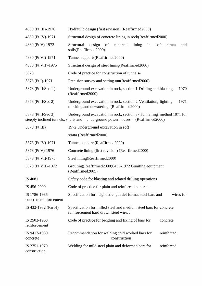
4880 (Pt III)-1976 Hydraulic design (first revision) (Reaffirmed2000)
4880 (Pt IV)-1971 Structural design of concrete lining in rock(Reaffirmed2000)
4880 (Pt V)-1972 Structural design of concrete lining in soft strata and
soils(Reaffirmed2000).
4880 (Pt VI)-1971 Tunnel supports(Reaffirmed2000)
4880 (Pt VII)-1975 Structural design of steel lining(Reaffirmed2000)
5878 Code of practice for construction of tunnels-
5878 (Pt I)-1971 Precision survey and setting out(Reaffirmed2000)
5878 (Pt II/Sec 1 ) Underground excavation in rock, section 1-Drilling and blasting. 1970
(Reaffirmed2000)
5878 (Pt II/Sec 2)- Underground excavation in rock, section 2-Ventilation, lighting 1971
mucking and dewatering. (Reaffirmed2000)
5878 (Pt II/Sec 3) Underground excavation in rock, section 3- Tunnelling method 1971 for
steeply inclined tunnels, shafts and underground power houses. (Reaffirmed2000)
5878 (Pt III) 1972 Underground excavation in soft
strata (Reaffirmed2000)
5878 (Pt IV)-1971 Tunnel supports(Reaffirmed2000)
5878 (Pt V)-1976 Concrete lining (first revision) (Reaffirmed2000)
5878 (Pt VI)-1975 Steel lining(Reaffirmed2000)
5878 (Pt VII)-1972 Grouting(Reaffirmed2000)6433-1972 Guniting equipment
(Reaffirmed2005)
IS 4081 Safety code for blasting and related drilling operations
IS 456-2000 Code of practice for plain and reinforced concrete.
IS 1786-1985 Specification for height strength def format steel bars and wires for
concrete reinforcement
IS 432-1982 (Part-I) Specification for milled steel and medium steel bars for concrete
reinforcement hard drawn steel wire. .
IS 2502-1963 Code of practice for bending and fixing of bars for concrete
reinforcement
IS 9417-1989 Recommendation for welding cold worked bars for reinforced
concrete construction
IS 2751-1979 Welding for mild steel plain and deformed bars for reinforced
construction
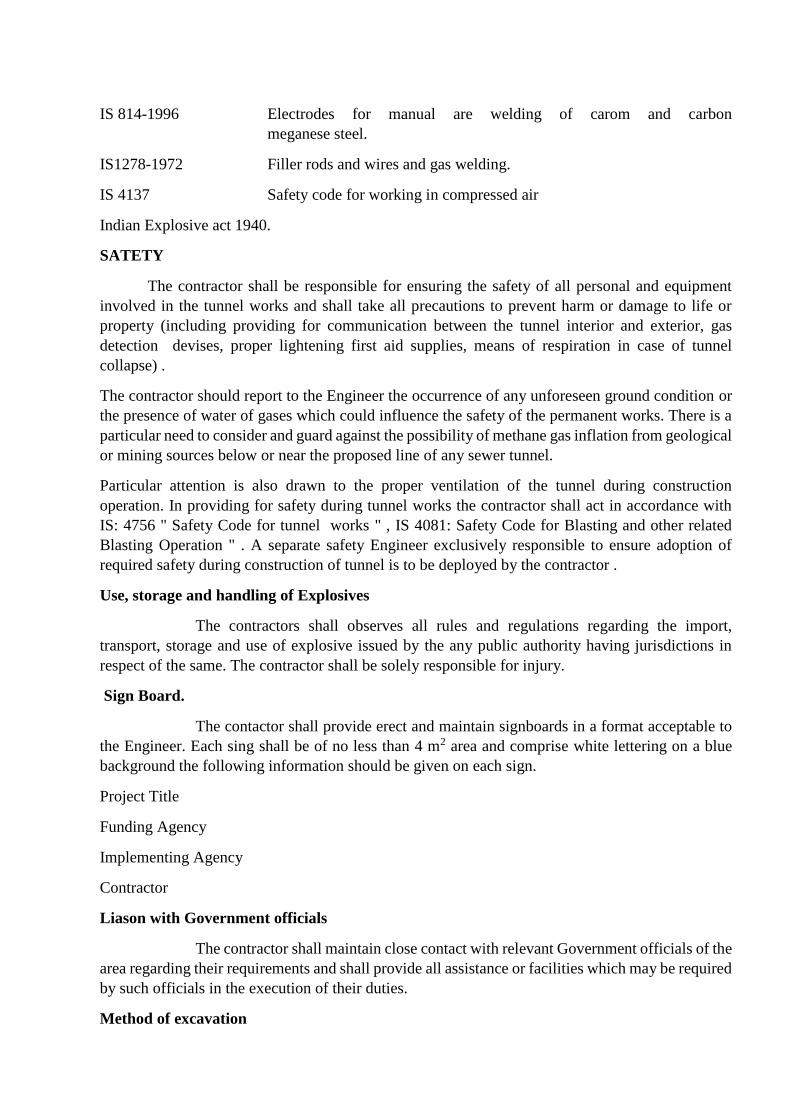
IS 814-1996 Electrodes for manual are welding of carom and carbon
meganese steel.
IS1278-1972 Filler rods and wires and gas welding.
IS 4137 Safety code for working in compressed air
Indian Explosive act 1940.
SATETY
The contractor shall be responsible for ensuring the safety of all personal and equipment
involved in the tunnel works and shall take all precautions to prevent harm or damage to life or
property (including providing for communication between the tunnel interior and exterior, gas
detection devises, proper lightening first aid supplies, means of respiration in case of tunnel
collapse) .
The contractor should report to the Engineer the occurrence of any unforeseen ground condition or
the presence of water of gases which could influence the safety of the permanent works. There is a
particular need to consider and guard against the possibility of methane gas inflation from geological
or mining sources below or near the proposed line of any sewer tunnel.
Particular attention is also drawn to the proper ventilation of the tunnel during construction
operation. In providing for safety during tunnel works the contractor shall act in accordance with
IS: 4756 " Safety Code for tunnel works " , IS 4081: Safety Code for Blasting and other related
Blasting Operation " . A separate safety Engineer exclusively responsible to ensure adoption of
required safety during construction of tunnel is to be deployed by the contractor .
Use, storage and handling of Explosives
The contractors shall observes all rules and regulations regarding the import,
transport, storage and use of explosive issued by the any public authority having jurisdictions in
respect of the same. The contractor shall be solely responsible for injury.
Sign Board.
The contactor shall provide erect and maintain signboards in a format acceptable to
the Engineer. Each sing shall be of no less than 4 m2 area and comprise white lettering on a blue
background the following information should be given on each sign.
Project Title
Funding Agency
Implementing Agency
Contractor
Liason with Government officials
The contractor shall maintain close contact with relevant Government officials of the
area regarding their requirements and shall provide all assistance or facilities which may be required
by such officials in the execution of their duties.
Method of excavation
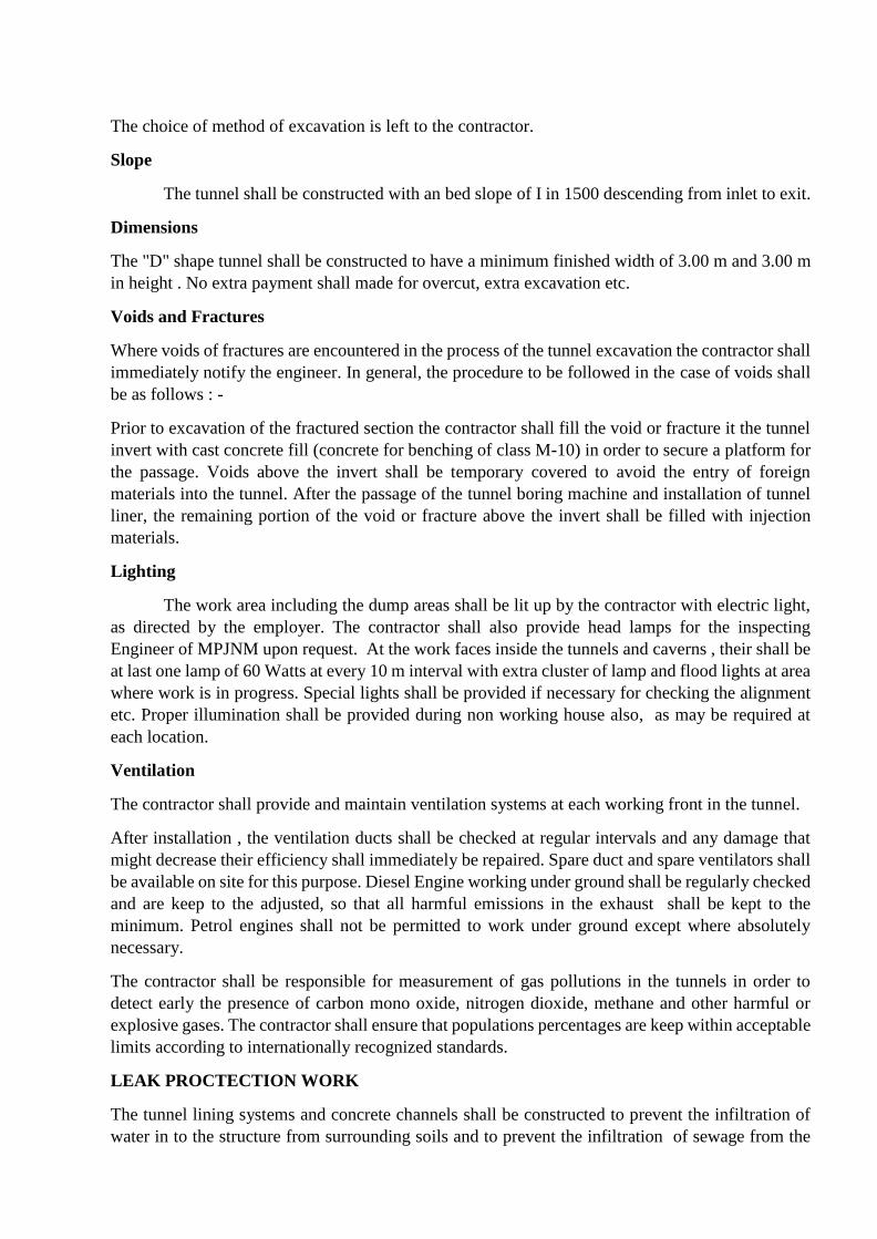
The choice of method of excavation is left to the contractor.
Slope
The tunnel shall be constructed with an bed slope of I in 1500 descending from inlet to exit.
Dimensions
The "D" shape tunnel shall be constructed to have a minimum finished width of 3.00 m and 3.00 m
in height . No extra payment shall made for overcut, extra excavation etc.
Voids and Fractures
Where voids of fractures are encountered in the process of the tunnel excavation the contractor shall
immediately notify the engineer. In general, the procedure to be followed in the case of voids shall
be as follows : -
Prior to excavation of the fractured section the contractor shall fill the void or fracture it the tunnel
invert with cast concrete fill (concrete for benching of class M-10) in order to secure a platform for
the passage. Voids above the invert shall be temporary covered to avoid the entry of foreign
materials into the tunnel. After the passage of the tunnel boring machine and installation of tunnel
liner, the remaining portion of the void or fracture above the invert shall be filled with injection
materials.
Lighting
The work area including the dump areas shall be lit up by the contractor with electric light,
as directed by the employer. The contractor shall also provide head lamps for the inspecting
Engineer of MPJNM upon request. At the work faces inside the tunnels and caverns , their shall be
at last one lamp of 60 Watts at every 10 m interval with extra cluster of lamp and flood lights at area
where work is in progress. Special lights shall be provided if necessary for checking the alignment
etc. Proper illumination shall be provided during non working house also, as may be required at
each location.
Ventilation
The contractor shall provide and maintain ventilation systems at each working front in the tunnel.
After installation , the ventilation ducts shall be checked at regular intervals and any damage that
might decrease their efficiency shall immediately be repaired. Spare duct and spare ventilators shall
be available on site for this purpose. Diesel Engine working under ground shall be regularly checked
and are keep to the adjusted, so that all harmful emissions in the exhaust shall be kept to the
minimum. Petrol engines shall not be permitted to work under ground except where absolutely
necessary.
The contractor shall be responsible for measurement of gas pollutions in the tunnels in order to
detect early the presence of carbon mono oxide, nitrogen dioxide, methane and other harmful or
explosive gases. The contractor shall ensure that populations percentages are keep within acceptable
limits according to internationally recognized standards.
LEAK PROCTECTION WORK
The tunnel lining systems and concrete channels shall be constructed to prevent the infiltration of
water in to the structure from surrounding soils and to prevent the infiltration of sewage from the

structure to surrounding soils. Measures to provide for water tightness shall be in accordance with
BS 8007. Water stop shall be provided at all constriction joints along the tunnel.
The specifications given herein are minimum required specifications. If during design or any other
stage higher specifications are required, the contractor will have to do so and no extra payment for
that will be payable.
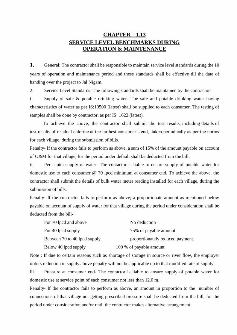
CHAPTER – 1.13
SERVICE LEVEL BENCHMARKS DURING
OPERATION & MAINTENANCE
1. General: The contractor shall be responsible to maintain service level standards during the 10
years of operation and maintenance period and these standards shall be effective till the date of
handing over the project to Jal Nigam.
2. Service Level Standards: The following standards shall be maintained by the contractor-
i. Supply of safe & potable drinking water- The safe and potable drinking water having
characteristics of water as per IS:10500 (latest) shall be supplied to each consumer. The testing of
samples shall be done by contractor, as per IS: 1622 (latest).
To achieve the above, the contractor shall submit the test results, including details of
test results of residual chlorine at the farthest consumer’s end, taken periodically as per the norms
for each village, during the submission of bills.
Penalty- If the contractor fails to perform as above, a sum of 15% of the amount payable on account
of O&M for that village, for the period under default shall be deducted from the bill.
ii. Per capita supply of water- The contactor is liable to ensure supply of potable water for
domestic use to each consumer @ 70 lpcd minimum at consumer end. To achieve the above, the
contractor shall submit the details of bulk water meter reading installed for each village, during the
submission of bills.
Penalty- If the contractor fails to perform as above; a proportionate amount as mentioned below
payable on account of supply of water for that village during the period under consideration shall be
deducted from the bill-
For 70 lpcd and above No deduction
For 40 lpcd supply 75% of payable amount
Between 70 to 40 lpcd supply proportionately reduced payment.
Below 40 lpcd supply 100 % of payable amount
Note : If due to certain reasons such as shortage of storage in source or river flow, the employer
orders reduction in supply above penalty will not be applicable up to that modified rate of supply
iii. Pressure at consumer end- The contactor is liable to ensure supply of potable water for
domestic use at service point of each consumer not less than 12.0 m.
Penalty- If the contractor fails to perform as above, an amount in proportion to the number of
connections of that village not getting prescribed pressure shall be deducted from the bill, for the
period under consideration and/or until the contractor makes alternative arrangement.
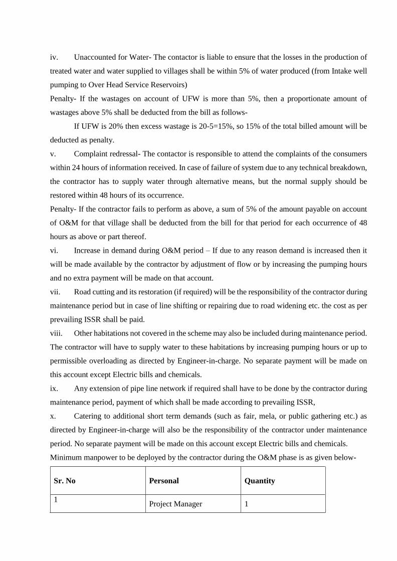
iv. Unaccounted for Water- The contactor is liable to ensure that the losses in the production of
treated water and water supplied to villages shall be within 5% of water produced (from Intake well
pumping to Over Head Service Reservoirs)
Penalty- If the wastages on account of UFW is more than 5%, then a proportionate amount of
wastages above 5% shall be deducted from the bill as follows-
If UFW is 20% then excess wastage is 20-5=15%, so 15% of the total billed amount will be
deducted as penalty.
v. Complaint redressal- The contactor is responsible to attend the complaints of the consumers
within 24 hours of information received. In case of failure of system due to any technical breakdown,
the contractor has to supply water through alternative means, but the normal supply should be
restored within 48 hours of its occurrence.
Penalty- If the contractor fails to perform as above, a sum of 5% of the amount payable on account
of O&M for that village shall be deducted from the bill for that period for each occurrence of 48
hours as above or part thereof.
vi. Increase in demand during O&M period – If due to any reason demand is increased then it
will be made available by the contractor by adjustment of flow or by increasing the pumping hours
and no extra payment will be made on that account.
vii. Road cutting and its restoration (if required) will be the responsibility of the contractor during
maintenance period but in case of line shifting or repairing due to road widening etc. the cost as per
prevailing ISSR shall be paid.
viii. Other habitations not covered in the scheme may also be included during maintenance period.
The contractor will have to supply water to these habitations by increasing pumping hours or up to
permissible overloading as directed by Engineer-in-charge. No separate payment will be made on
this account except Electric bills and chemicals.
ix. Any extension of pipe line network if required shall have to be done by the contractor during
maintenance period, payment of which shall be made according to prevailing ISSR,
x. Catering to additional short term demands (such as fair, mela, or public gathering etc.) as
directed by Engineer-in-charge will also be the responsibility of the contractor under maintenance
period. No separate payment will be made on this account except Electric bills and chemicals.
Minimum manpower to be deployed by the contractor during the O&M phase is as given below-
Sr. No
Personal Quantity
1 Project Manager 1
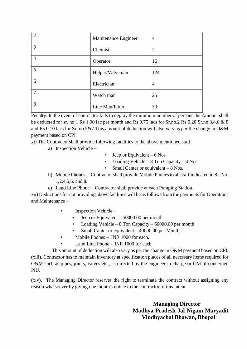
2 Maintenance Engineer 4
3 Chemist 2
4 Operator 16
5 Helper/Valveman 124
6 Electrician 4
7 Watch man 25
8 Line Man/Fitter 30
Penalty: In the event of contractor fails to deploy the minimum number of persons the Amount shall
be deducted for sr. no 1 Rs 1.00 lac per month and Rs 0.75 lacs for Sr.no.2 Rs 0.20 Sr.no 3,4,6 & 8
and Rs 0.10 lacs for Sr. no 5&7.This amount of deduction will also vary as per the change in O&M
payment based on CPI.
xi) The Contractor shall provide following facilities to the above mentioned staff –
a) Inspection Vehicle –
• Jeep or Equivalent – 6 Nos
• Loading Vehicle – 8 Ton Capacity – 4 Nos
• Small Canter or equivalent – 8 Nos.
b) Mobile Phones – Contractor shall provide Mobile Phones to all staff indicated in Sr. No.
1,2,4,5,6, and 8.
c) Land Line Phone - Contractor shall provide at each Pumping Station.
xii) Deductions for not providing above facilities will be as follows from the payments for Operations
and Maintenance –
• Inspection Vehicle –
• Jeep or Equivalent – 50000.00 per month
• Loading Vehicle – 8 Ton Capacity – 60000.00 per month
• Small Canter or equivalent – 40000.00 per Month.
• Mobile Phones – INR 1000 for each.
• Land Line Phone - INR 1000 for each.
This amount of deduction will also vary as per the change in O&M payment based on CPI.
(xiii). Contractor has to maintain inventory at specification places of all necessary items required for
O&M such as pipes, joints, valves etc., as directed by the engineer-in-charge or GM of concerned
PIU.
(xiv). The Managing Director reserves the right to terminate the contract without assigning any
reason whatsoever by giving one month's notice to the contractor of this intent.
Managing Director
Madhya Pradesh Jal Nigam Maryadit
Vindhyachal Bhawan, Bhopal
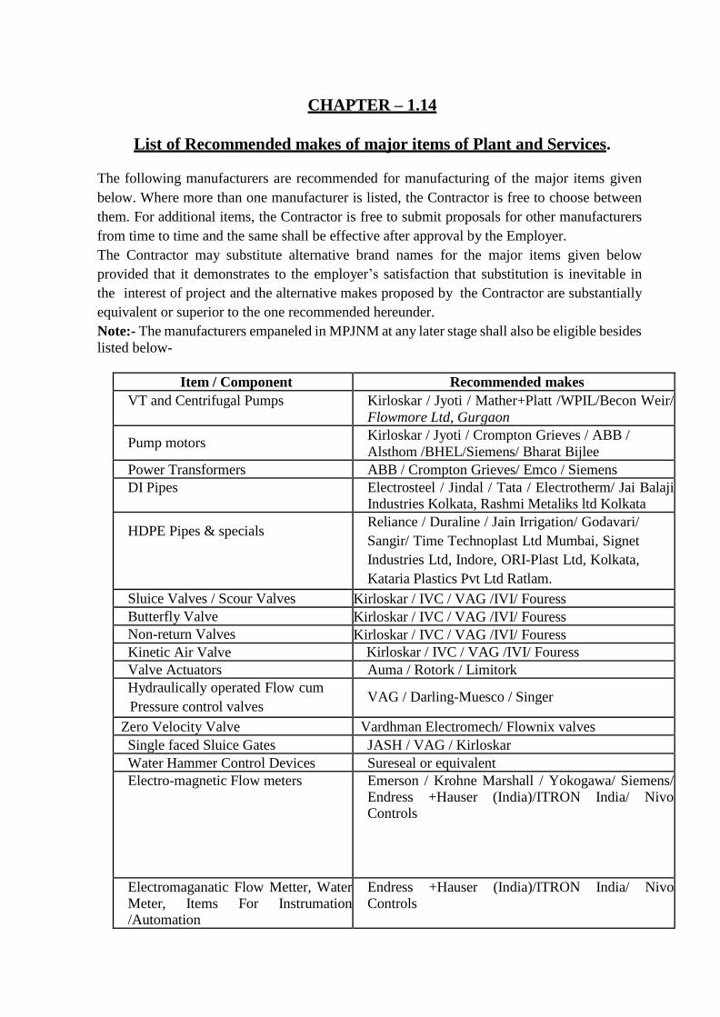
CHAPTER – 1.14
List of Recommended makes of major items of Plant and Services.
The following manufacturers are recommended for manufacturing of the major items given
below. Where more than one manufacturer is listed, the Contractor is free to choose between
them. For additional items, the Contractor is free to submit proposals for other manufacturers
from time to time and the same shall be effective after approval by the Employer.
The Contractor may substitute alternative brand names for the major items given below
provided that it demonstrates to the employer’s satisfaction that substitution is inevitable in
the interest of project and the alternative makes proposed by the Contractor are substantially
equivalent or superior to the one recommended hereunder.
Note:- The manufacturers empaneled in MPJNM at any later stage shall also be eligible besides
listed below-
Item / Component Recommended makes
VT and Centrifugal Pumps Kirloskar / Jyoti / Mather+Platt /WPIL/Becon Weir/
Flowmore Ltd, Gurgaon
Pump motors Kirloskar / Jyoti / Crompton Grieves / ABB /
Alsthom /BHEL/Siemens/ Bharat Bijlee
Power Transformers ABB / Crompton Grieves/ Emco / Siemens
DI Pipes Electrosteel / Jindal / Tata / Electrotherm/ Jai Balaji Industries Kolkata, Rashmi Metaliks ltd Kolkata
HDPE Pipes & specials Reliance / Duraline / Jain Irrigation/ Godavari/
Sangir/ Time Technoplast Ltd Mumbai, Signet
Industries Ltd, Indore, ORI-Plast Ltd, Kolkata,
Kataria Plastics Pvt Ltd Ratlam.
Sluice Valves / Scour Valves Kirloskar / IVC / VAG /IVI/ Fouress
Butterfly Valve Kirloskar / IVC / VAG /IVI/ Fouress
Non-return Valves Kirloskar / IVC / VAG /IVI/ Fouress
Kinetic Air Valve Kirloskar / IVC / VAG /IVI/ Fouress
Valve Actuators Auma / Rotork / Limitork
Hydraulically operated Flow cum
Pressure control valves VAG / Darling-Muesco / Singer
Zero Velocity Valve Vardhman Electromech/ Flownix valves
Single faced Sluice Gates JASH / VAG / Kirloskar
Water Hammer Control Devices Sureseal or equivalent
Electro-magnetic Flow meters Emerson / Krohne Marshall / Yokogawa/ Siemens/ Endress +Hauser (India)/ITRON India/ Nivo Controls
Electromaganatic Flow Metter, Water Meter, Items For Instrumation /Automation
Endress +Hauser (India)/ITRON India/ Nivo Controls
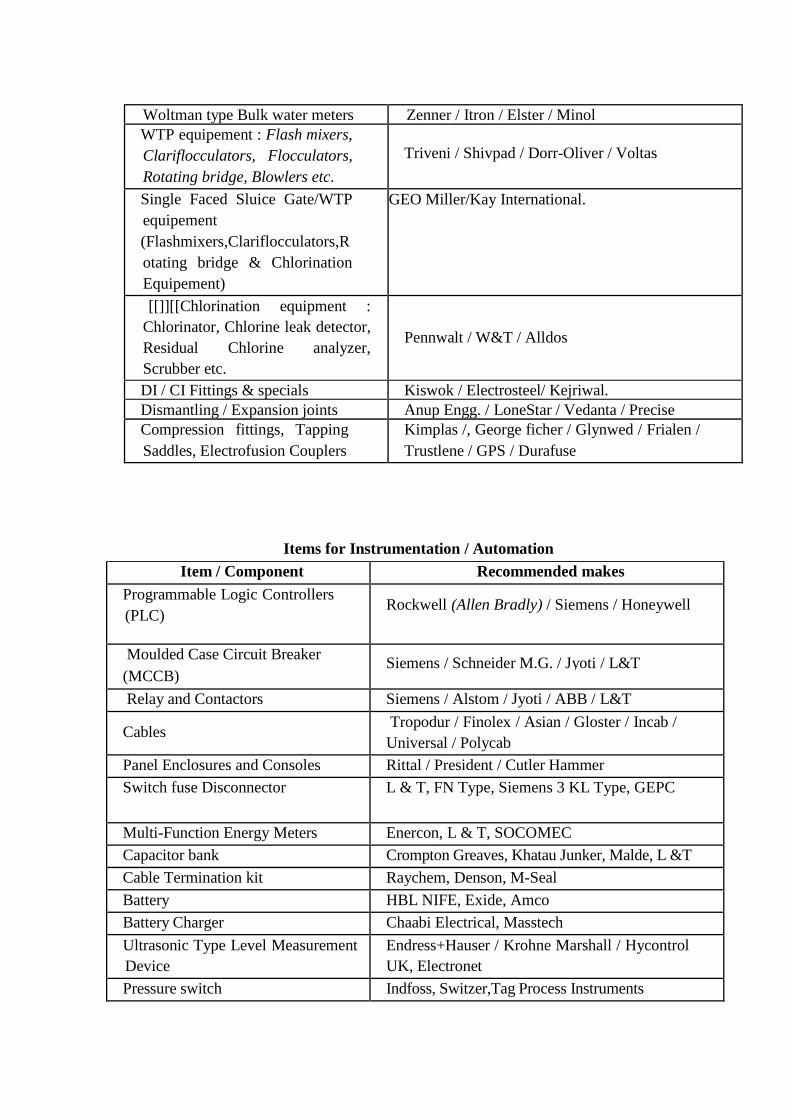
Woltman type Bulk water meters Zenner / Itron / Elster / Minol
WTP equipement : Flash mixers,
Clariflocculators, Flocculators,
Rotating bridge, Blowlers etc.
Triveni / Shivpad / Dorr-Oliver / Voltas
Single Faced Sluice Gate/WTP
equipement
(Flashmixers,Clariflocculators,R
otating bridge & Chlorination
Equipement)
GEO Miller/Kay International.
[[]][[Chlorination equipment :
Chlorinator, Chlorine leak detector,
Residual Chlorine analyzer,
Scrubber etc.
Pennwalt / W&T / Alldos
DI / CI Fittings & specials Kiswok / Electrosteel/ Kejriwal.
Dismantling / Expansion joints Anup Engg. / LoneStar / Vedanta / Precise
Compression fittings, Tapping
Saddles, Electrofusion Couplers
Kimplas /, George ficher / Glynwed / Frialen /
Trustlene / GPS / Durafuse
Items for Instrumentation / Automation
Item / Component Recommended makes
Programmable Logic Controllers
(PLC) Rockwell (Allen Bradly) / Siemens / Honeywell
Moulded Case Circuit Breaker Siemens / Schneider M.G. / Jyoti / L&T
(MCCB)
Relay and Contactors Siemens / Alstom / Jyoti / ABB / L&T
Cables Tropodur / Finolex / Asian / Gloster / Incab /
Universal / Polycab
Panel Enclosures and Consoles Rittal / President / Cutler Hammer
Switch fuse Disconnector L & T, FN Type, Siemens 3 KL Type, GEPC
Multi-Function Energy Meters Enercon, L & T, SOCOMEC
Capacitor bank Crompton Greaves, Khatau Junker, Malde, L &T
Cable Termination kit Raychem, Denson, M-Seal
Battery HBL NIFE, Exide, Amco
Battery Charger Chaabi Electrical, Masstech
Ultrasonic Type Level Measurement
Device
Endress+Hauser / Krohne Marshall / Hycontrol
UK, Electronet
Pressure switch Indfoss, Switzer,Tag Process Instruments
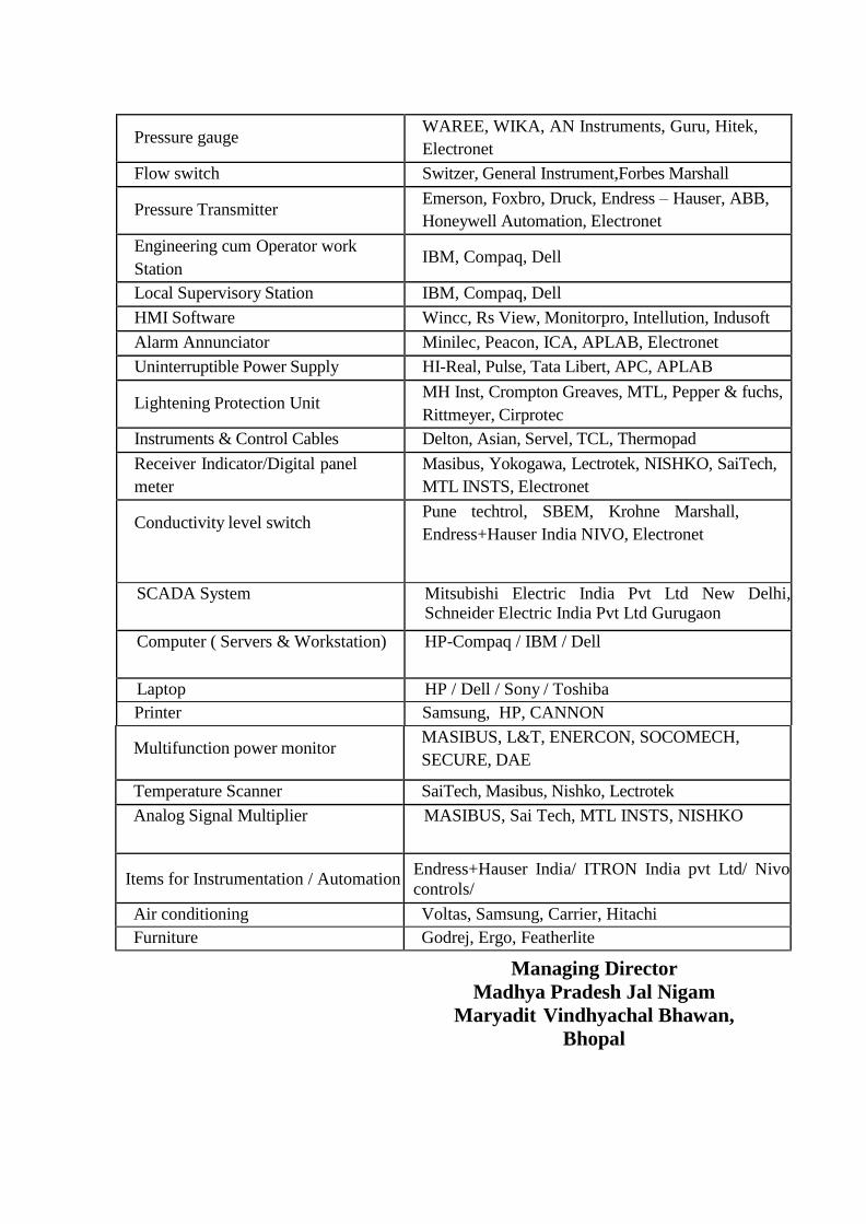
Pressure gauge WAREE, WIKA, AN Instruments, Guru, Hitek,
Electronet
Flow switch Switzer, General Instrument,Forbes Marshall
Pressure Transmitter Emerson, Foxbro, Druck, Endress – Hauser, ABB,
Honeywell Automation, Electronet
Engineering cum Operator work
Station IBM, Compaq, Dell
Local Supervisory Station IBM, Compaq, Dell
HMI Software Wincc, Rs View, Monitorpro, Intellution, Indusoft
Alarm Annunciator Minilec, Peacon, ICA, APLAB, Electronet
Uninterruptible Power Supply HI-Real, Pulse, Tata Libert, APC, APLAB
Lightening Protection Unit MH Inst, Crompton Greaves, MTL, Pepper & fuchs,
Rittmeyer, Cirprotec
Instruments & Control Cables Delton, Asian, Servel, TCL, Thermopad
Receiver Indicator/Digital panel
meter
Masibus, Yokogawa, Lectrotek, NISHKO, SaiTech,
MTL INSTS, Electronet
Conductivity level switch Pune techtrol, SBEM, Krohne Marshall,
Endress+Hauser India NIVO, Electronet
SCADA System Mitsubishi Electric India Pvt Ltd New Delhi, Schneider Electric India Pvt Ltd Gurugaon
Computer ( Servers & Workstation) HP-Compaq / IBM / Dell
Laptop HP / Dell / Sony / Toshiba
Printer Samsung, HP, CANNON
Multifunction power monitor MASIBUS, L&T, ENERCON, SOCOMECH,
SECURE, DAE
Temperature Scanner SaiTech, Masibus, Nishko, Lectrotek
Analog Signal Multiplier MASIBUS, Sai Tech, MTL INSTS, NISHKO
Items for Instrumentation / Automation Endress+Hauser India/ ITRON India pvt Ltd/ Nivo
controls/
Air conditioning Voltas, Samsung, Carrier, Hitachi
Furniture Godrej, Ergo, Featherlite
Managing Director
Madhya Pradesh Jal Nigam
Maryadit Vindhyachal Bhawan,
Bhopal

CHAPTER – 1.15
TRIAL RUN FOR 3 MONTHS AND OPERATION & MAINTENANCE
FOR 10 YEARS
1. General: The scope of work under this contract includes trial run and maintenance of
the scheme as a whole and its parts as an individual component as well. Under this
trial run period of 3 months after the completion of works (Defect liability
period is upto the end of Operation and Maintenance period which will start after trial run
of 3 months) in all respects, the contractor has to run the scheme completely and will
have to prove performance of each component individually and of whole scheme as
per the standards laid down in contract. After completion of three months trial run
the whole scheme shall be operated and maintained for 10 (Ten) years and then
shall be handed over to Madhya Pradesh Jal Nigam Maryadit.
During this period the contractor shall have to appoint necessary staff for running and
maintenance of scheme. The candidature of the staff being engaged by contractor shall
have to be approved by the Engineer In charge. During this period the staff engaged
for running and maintenance of scheme will be paid by the contractor as per the wages
rules and all the responsibilities of employees regarding safety/ insurance etc. will be of
the contractor.
During the last three months period of O&M, the Nigam will appoint staff to get hands
on training to run and maintain the scheme. Contractor and his staff will arrange
training for the staff to the satisfaction of Engineer In-charge.
2. The period of trial run shall be three calendar months from the date of actual
commissioning of scheme as certified by the Engineer-In-charge. The period of 10 years
O&M shall be from the date of actual completion of trial run of the scheme as certified by
the Engineer-In-charge
3. Intake Well cum pump house: The contractor will provide the staff to run and
maintain and keep records of the machinery and equipments, installed in intake well.
The electricity charges (excluding penalties) will be borne by MPJNM, initial
inventory of the consumables like oil, Grease, Gland packing; all type of fuses, T & P
etc. will be provided by the contractor at his own cost and expenses. The contractor
shall have to maintain consumption and stock of the inventory so as not to interrupt the
water supply. The contractor shall have to arrange for security, watch and maintain the
premises of intake well and approach bridge & road during this period.
4. Raw and Clear water pumping Mains: The contractor will have to arrange and
provide for regular surveillance of pumping mains from Intake well cum pump house
structure to treatment plant and up to MBRs and OHTs, and will have to arrange for any
repairs and maintenance during the trial run and O&M period, including damage done by
human interference or by machinery or traffic, contractor however will be free to claim
compensation on such grounds from the party responsible for such damages as admissible.
All necessary T&P, consumables, pipes etc. will be provided by the contractor at his own
cost and expenses.
5. Treatment Plant and Pump House: The contractor will provide necessary staff to run

and maintain the treatment plant the cost of chlorine, alum, lime and other chemicals
used in laboratory. The electricity charges (excluding penalties) consumed/used
during the treatment process will be borne by the MPJNM.
The contractor will maintain the record of consumption of chemicals and inventory of
stock and will apprise the Engineer in charge of shortcomings. The contractor will
bring in the notice of Engineer in charge all repairs and maintenance works done during
the day and will generate and submit reports on each important parameter being
monitored and an alarm enunciated during the day.
The contractor shall arrange for the training of the staff as nominated by the Engineer in
charge to run and maintain the plant and pump house three months prior to completion of
10 years O&M period- up to the satisfaction of Engineer in charge.
The contractor shall have to arrange and provide for watch and ward, security and
upkeep of premises of the plant during trial run period and O&M period. He will
maintain/replace the furniture/ equipment etc. if damaged during this period.
6. Master Balancing Reservoirs/GLR/ESR: The contractor will provide necessary
staff for watch and ward and maintenance of break pressure tanks and all over head
tanks under this project and will upkeep the premises of the tanks to the satisfaction
of Engineer in Charge. The contractor's staff will maintain the record of water level
in tanks and stock of inventory if any at these tanks.
7. Gravity Feeder Mains: The contractor will have to arrange and provide for regular
surveillance of gravity feeder mains from Break Pressure Tanks to all Overhead tanks
of the villages and will have to arrange for any repairs and maintenance including damage
done by human interference or by machinery or traffic, contractor however will be free
to claim compensation on such grounds from the party responsible for such damages as
admissible, the MPJNM will help in certifying the quantum of such damage during the
trial run and O&M period. All necessary T&P, consumables, pipes etc. will be provided
by the contractor at his own cost and expenses.
8. Electrical Substations and Electric Supply Line: The contractor will provide
necessary staff and arrange for the maintenance/ repairs of electrical substations and
systems developed/ constructed under this contract at intake well, treatment plant and in
the other premises. All expenses to operate and maintain shall be borne by the
contractor, except the energy charges excluding penalties etc.
After successful completion of trial run and O&M period (to be certified by the Engineer
in Charge) the scheme as a whole and its components individually will be handed
over to MPJNM for further running and maintenance.
8. Operation & Maintenance of distribution system:- The contractor is liable and
responsible for all the works which have been executed under the contract including
damage done by human interference or by machinery or traffic, contractor however will
be free to claim compensation on such grounds from the party responsible for such
damages as admissible, the MPJNM will help in certifying the quantum of such damage.
The O&M of ESRs of the villages and distribution systems are also in the scope of
contractor. Daily operation of valves, beyond the ESRs, within the village for
distribution shall be done by Gram Panchayat. Please also refer Chapter on ‘Service
Level Benchmarks during Operation & Maintenance’.
9. Handing Over after O&M period: Before handing over the components to MPJNM
all the structures shall be finished by painting as per specifications given in the
agreement and all the Electrical & Mechanical equipments shall be finished by painting
as per specifications and these must be in good running conditions.
It will be the responsibility of the contractor to show that all stipulated Service Level
Standards have been fulfilled and are up to the mark on the date of handing over the
works to MPJNM.
The MPJNM will not take any responsibility of the employees engaged by the
contractor to run the scheme during trial run and O&M period. The scheme and all its
components individually shall be handed over to MPJNM in a very good maintained
condition. (Decision of Engineer in Charge will be final in this regard).
Managing Director
Madhya Pradesh Jal Nigam
Maryadit Vindhyachal
Bhawan, Bhopal
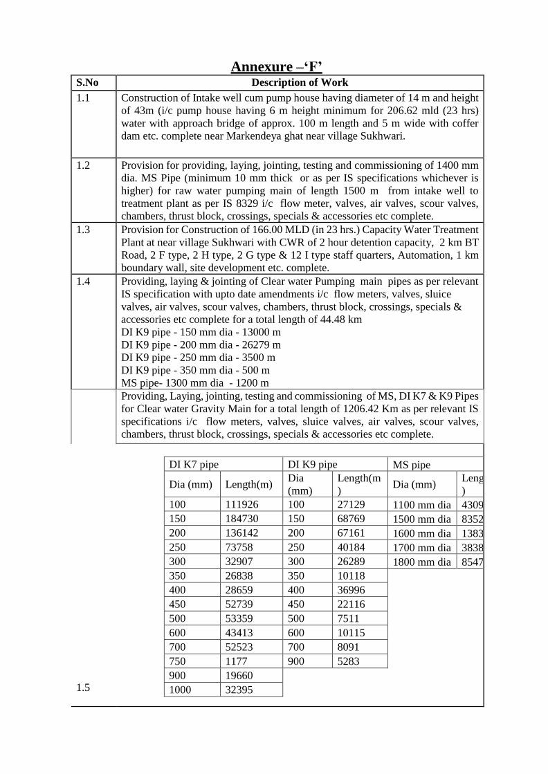
Annexure –‘F’ S.No Description of Work
1.1 Construction of Intake well cum pump house having diameter of 14 m and height
of 43m (i/c pump house having 6 m height minimum for 206.62 mld (23 hrs)
water with approach bridge of approx. 100 m length and 5 m wide with coffer
dam etc. complete near Markendeya ghat near village Sukhwari.
1.2 Provision for providing, laying, jointing, testing and commissioning of 1400 mm
dia. MS Pipe (minimum 10 mm thick or as per IS specifications whichever is
higher) for raw water pumping main of length 1500 m from intake well to
treatment plant as per IS 8329 i/c flow meter, valves, air valves, scour valves,
chambers, thrust block, crossings, specials & accessories etc complete.
1.3 Provision for Construction of 166.00 MLD (in 23 hrs.) Capacity Water Treatment
Plant at near village Sukhwari with CWR of 2 hour detention capacity, 2 km BT
Road, 2 F type, 2 H type, 2 G type & 12 I type staff quarters, Automation, 1 km
boundary wall, site development etc. complete.
1.4 Providing, laying & jointing of Clear water Pumping main pipes as per relevant
IS specification with upto date amendments i/c flow meters, valves, sluice
valves, air valves, scour valves, chambers, thrust block, crossings, specials &
accessories etc complete for a total length of 44.48 km
DI K9 pipe - 150 mm dia - 13000 m
DI K9 pipe - 200 mm dia - 26279 m
DI K9 pipe - 250 mm dia - 3500 m
DI K9 pipe - 350 mm dia - 500 m
MS pipe- 1300 mm dia - 1200 m
1.5
Providing, Laying, jointing, testing and commissioning of MS, DI K7 & K9 Pipes
for Clear water Gravity Main for a total length of 1206.42 Km as per relevant IS
specifications i/c flow meters, valves, sluice valves, air valves, scour valves,
chambers, thrust block, crossings, specials & accessories etc complete.
DI K7 pipe DI K9 pipe MS pipe
Dia (mm) Length(m) Dia
(mm)
Length(m
) Dia (mm)
Length(m
)
100 111926 100 27129 1100 mm dia 4309
150 184730 150 68769 1500 mm dia 8352
200 136142 200 67161 1600 mm dia 1383
250 73758 250 40184 1700 mm dia 3838
300 32907 300 26289 1800 mm dia 8547
350 26838 350 10118 400 28659 400 36996 450 52739 450 22116 500 53359 500 7511 600 43413 600 10115 700 52523 700 8091 750 1177 900 5283 900 19660 1000 32395
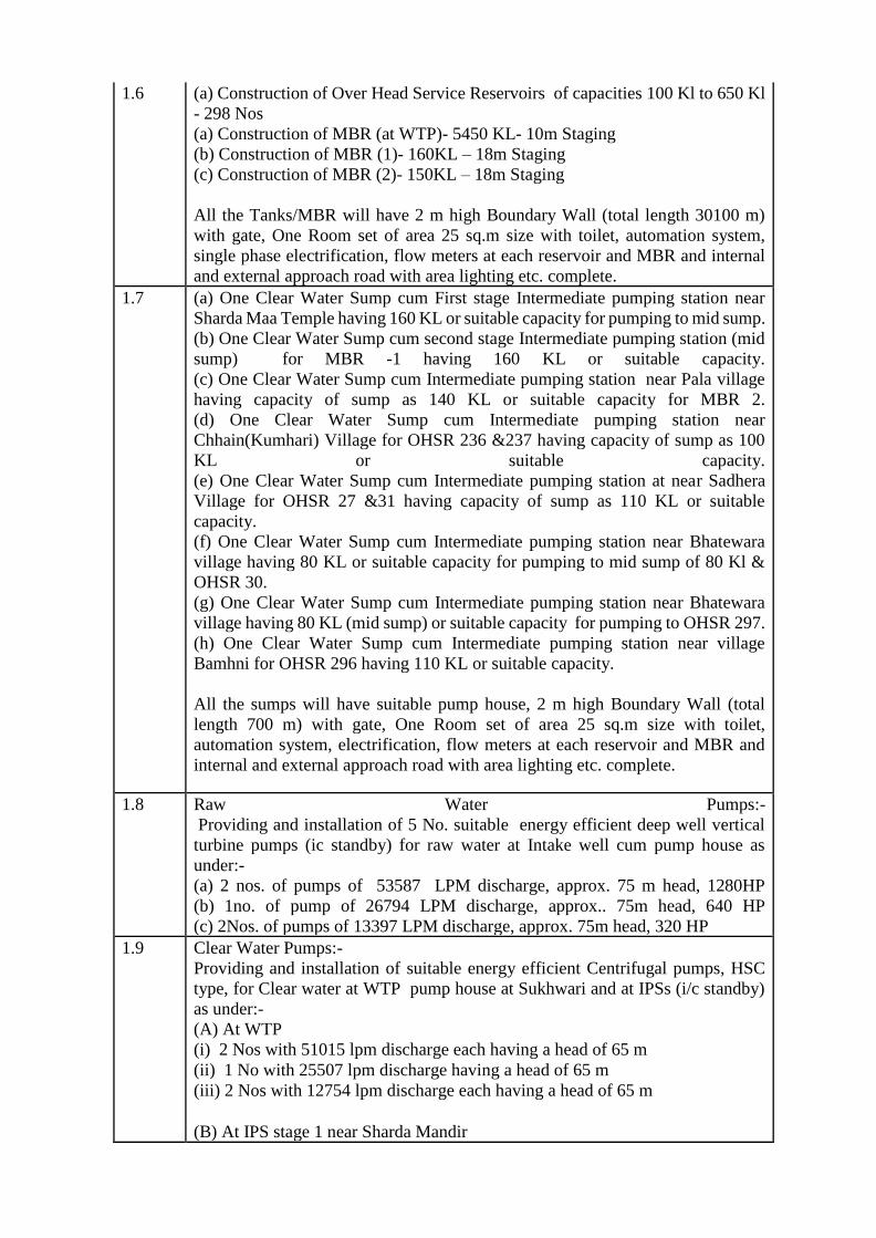
1.6 (a) Construction of Over Head Service Reservoirs of capacities 100 Kl to 650 Kl
- 298 Nos
(a) Construction of MBR (at WTP)- 5450 KL- 10m Staging
(b) Construction of MBR (1)- 160KL – 18m Staging
(c) Construction of MBR (2)- 150KL – 18m Staging
All the Tanks/MBR will have 2 m high Boundary Wall (total length 30100 m)
with gate, One Room set of area 25 sq.m size with toilet, automation system,
single phase electrification, flow meters at each reservoir and MBR and internal
and external approach road with area lighting etc. complete.
1.7 (a) One Clear Water Sump cum First stage Intermediate pumping station near
Sharda Maa Temple having 160 KL or suitable capacity for pumping to mid sump.
(b) One Clear Water Sump cum second stage Intermediate pumping station (mid
sump) for MBR -1 having 160 KL or suitable capacity.
(c) One Clear Water Sump cum Intermediate pumping station near Pala village
having capacity of sump as 140 KL or suitable capacity for MBR 2.
(d) One Clear Water Sump cum Intermediate pumping station near
Chhain(Kumhari) Village for OHSR 236 &237 having capacity of sump as 100
KL or suitable capacity.
(e) One Clear Water Sump cum Intermediate pumping station at near Sadhera
Village for OHSR 27 &31 having capacity of sump as 110 KL or suitable
capacity.
(f) One Clear Water Sump cum Intermediate pumping station near Bhatewara
village having 80 KL or suitable capacity for pumping to mid sump of 80 Kl &
OHSR 30.
(g) One Clear Water Sump cum Intermediate pumping station near Bhatewara
village having 80 KL (mid sump) or suitable capacity for pumping to OHSR 297.
(h) One Clear Water Sump cum Intermediate pumping station near village
Bamhni for OHSR 296 having 110 KL or suitable capacity.
All the sumps will have suitable pump house, 2 m high Boundary Wall (total
length 700 m) with gate, One Room set of area 25 sq.m size with toilet,
automation system, electrification, flow meters at each reservoir and MBR and
internal and external approach road with area lighting etc. complete.
1.8 Raw Water Pumps:-
Providing and installation of 5 No. suitable energy efficient deep well vertical
turbine pumps (ic standby) for raw water at Intake well cum pump house as
under:-
(a) 2 nos. of pumps of 53587 LPM discharge, approx. 75 m head, 1280HP
(b) 1no. of pump of 26794 LPM discharge, approx.. 75m head, 640 HP
(c) 2Nos. of pumps of 13397 LPM discharge, approx. 75m head, 320 HP
1.9 Clear Water Pumps:-
Providing and installation of suitable energy efficient Centrifugal pumps, HSC
type, for Clear water at WTP pump house at Sukhwari and at IPSs (i/c standby)
as under:-
(A) At WTP
(i) 2 Nos with 51015 lpm discharge each having a head of 65 m
(ii) 1 No with 25507 lpm discharge having a head of 65 m
(iii) 2 Nos with 12754 lpm discharge each having a head of 65 m
(B) At IPS stage 1 near Sharda Mandir
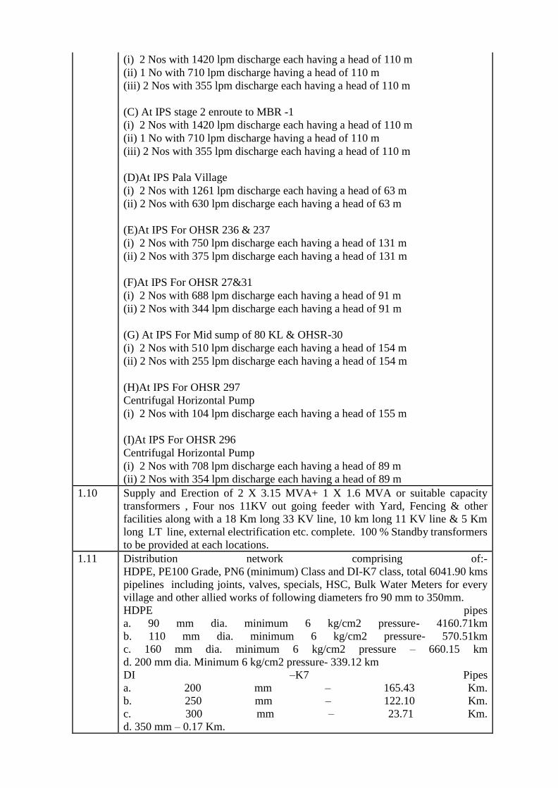
(i) 2 Nos with 1420 lpm discharge each having a head of 110 m
(ii) 1 No with 710 lpm discharge having a head of 110 m
(iii) 2 Nos with 355 lpm discharge each having a head of 110 m
(C) At IPS stage 2 enroute to MBR -1
(i) 2 Nos with 1420 lpm discharge each having a head of 110 m
(ii) 1 No with 710 lpm discharge having a head of 110 m
(iii) 2 Nos with 355 lpm discharge each having a head of 110 m
(D)At IPS Pala Village
(i) 2 Nos with 1261 lpm discharge each having a head of 63 m
(ii) 2 Nos with 630 lpm discharge each having a head of 63 m
(E)At IPS For OHSR 236 & 237
(i) 2 Nos with 750 lpm discharge each having a head of 131 m
(ii) 2 Nos with 375 lpm discharge each having a head of 131 m
(F)At IPS For OHSR 27&31
(i) 2 Nos with 688 lpm discharge each having a head of 91 m
(ii) 2 Nos with 344 lpm discharge each having a head of 91 m
(G) At IPS For Mid sump of 80 KL & OHSR-30
(i) 2 Nos with 510 lpm discharge each having a head of 154 m
(ii) 2 Nos with 255 lpm discharge each having a head of 154 m
(H)At IPS For OHSR 297
Centrifugal Horizontal Pump
(i) 2 Nos with 104 lpm discharge each having a head of 155 m
(I)At IPS For OHSR 296
Centrifugal Horizontal Pump
(i) 2 Nos with 708 lpm discharge each having a head of 89 m
(ii) 2 Nos with 354 lpm discharge each having a head of 89 m
1.10 Supply and Erection of 2 X 3.15 MVA+ 1 X 1.6 MVA or suitable capacity
transformers , Four nos 11KV out going feeder with Yard, Fencing & other
facilities along with a 18 Km long 33 KV line, 10 km long 11 KV line & 5 Km
long LT line, external electrification etc. complete. 100 % Standby transformers
to be provided at each locations.
1.11 Distribution network comprising of:-
HDPE, PE100 Grade, PN6 (minimum) Class and DI-K7 class, total 6041.90 kms
pipelines including joints, valves, specials, HSC, Bulk Water Meters for every
village and other allied works of following diameters fro 90 mm to 350mm.
HDPE pipes
a. 90 mm dia. minimum 6 kg/cm2 pressure- 4160.71km
b. 110 mm dia. minimum 6 kg/cm2 pressure- 570.51km
c. 160 mm dia. minimum 6 kg/cm2 pressure – 660.15 km
d. 200 mm dia. Minimum 6 kg/cm2 pressure- 339.12 km
DI –K7 Pipes
a. 200 mm – 165.43 Km.
b. 250 mm – 122.10 Km.
c. 300 mm – 23.71 Km.
d. 350 mm – 0.17 Km.
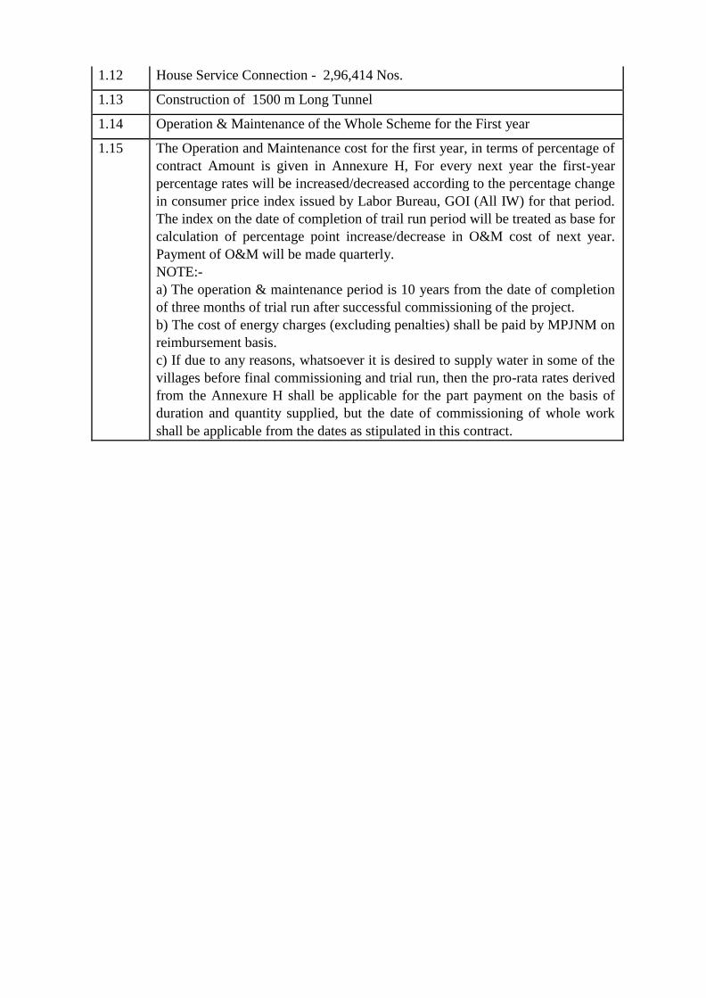
1.12 House Service Connection - 2,96,414 Nos.
1.13 Construction of 1500 m Long Tunnel
1.14 Operation & Maintenance of the Whole Scheme for the First year
1.15 The Operation and Maintenance cost for the first year, in terms of percentage of
contract Amount is given in Annexure H, For every next year the first-year
percentage rates will be increased/decreased according to the percentage change
in consumer price index issued by Labor Bureau, GOI (All IW) for that period.
The index on the date of completion of trail run period will be treated as base for
calculation of percentage point increase/decrease in O&M cost of next year.
Payment of O&M will be made quarterly.
NOTE:-
a) The operation & maintenance period is 10 years from the date of completion
of three months of trial run after successful commissioning of the project.
b) The cost of energy charges (excluding penalties) shall be paid by MPJNM on
reimbursement basis.
c) If due to any reasons, whatsoever it is desired to supply water in some of the
villages before final commissioning and trial run, then the pro-rata rates derived
from the Annexure H shall be applicable for the part payment on the basis of
duration and quantity supplied, but the date of commissioning of whole work
shall be applicable from the dates as stipulated in this contract.
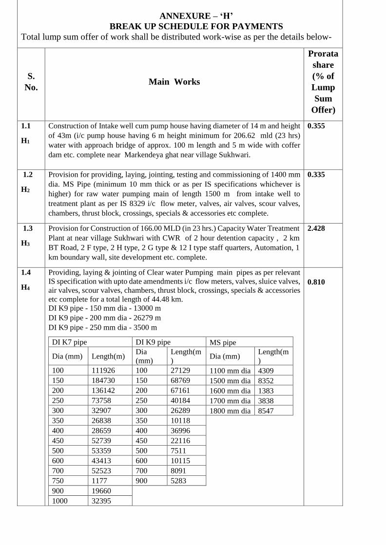
ANNEXURE – ‘H’
BREAK UP SCHEDULE FOR PAYMENTS
Total lump sum offer of work shall be distributed work-wise as per the details below-
S.
No. Main Works
Prorata
share
(% of
Lump
Sum
Offer)
1.1
H1
Construction of Intake well cum pump house having diameter of 14 m and height
of 43m (i/c pump house having 6 m height minimum for 206.62 mld (23 hrs)
water with approach bridge of approx. 100 m length and 5 m wide with coffer
dam etc. complete near Markendeya ghat near village Sukhwari.
0.355
1.2
H2
Provision for providing, laying, jointing, testing and commissioning of 1400 mm
dia. MS Pipe (minimum 10 mm thick or as per IS specifications whichever is
higher) for raw water pumping main of length 1500 m from intake well to
treatment plant as per IS 8329 i/c flow meter, valves, air valves, scour valves,
chambers, thrust block, crossings, specials & accessories etc complete.
0.335
1.3
H3
Provision for Construction of 166.00 MLD (in 23 hrs.) Capacity Water Treatment
Plant at near village Sukhwari with CWR of 2 hour detention capacity , 2 km
BT Road, 2 F type, 2 H type, 2 G type & 12 I type staff quarters, Automation, 1
km boundary wall, site development etc. complete.
2.428
1.4
H4
Providing, laying & jointing of Clear water Pumping main pipes as per relevant
IS specification with upto date amendments i/c flow meters, valves, sluice valves,
air valves, scour valves, chambers, thrust block, crossings, specials & accessories
etc complete for a total length of 44.48 km.
DI K7 pipe DI K9 pipe MS pipe
Dia (mm) Length(m) Dia
(mm)
Length(m
) Dia (mm)
Length(m
)
100 111926 100 27129 1100 mm dia 4309
150 184730 150 68769 1500 mm dia 8352
200 136142 200 67161 1600 mm dia 1383
250 73758 250 40184 1700 mm dia 3838
300 32907 300 26289 1800 mm dia 8547
350 26838 350 10118 400 28659 400 36996 450 52739 450 22116 500 53359 500 7511 600 43413 600 10115 700 52523 700 8091 750 1177 900 5283 900 19660 1000 32395
DI K9 pipe - 150 mm dia - 13000 m
DI K9 pipe - 200 mm dia - 26279 m
DI K9 pipe - 250 mm dia - 3500 m
0.810
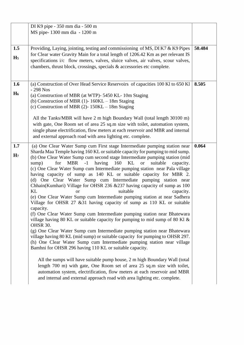
DI K9 pipe - 350 mm dia - 500 m
MS pipe- 1300 mm dia - 1200 m
1.5
H5
Providing, Laying, jointing, testing and commissioning of MS, DI K7 & K9 Pipes
for Clear water Gravity Main for a total length of 1206.42 Km as per relevant IS
specifications i/c flow meters, valves, sluice valves, air valves, scour valves,
chambers, thrust block, crossings, specials & accessories etc complete.
50.484
1.6
H6
(a) Construction of Over Head Service Reservoirs of capacities 100 Kl to 650 Kl
- 298 Nos
(a) Construction of MBR (at WTP)- 5450 KL- 10m Staging
(b) Construction of MBR (1)- 160KL – 18m Staging
(c) Construction of MBR (2)- 150KL – 18m Staging
All the Tanks/MBR will have 2 m high Boundary Wall (total length 30100 m)
with gate, One Room set of area 25 sq.m size with toilet, automation system,
single phase electrification, flow meters at each reservoir and MBR and internal
and external approach road with area lighting etc. complete.
8.505
1.7
H7
(a) One Clear Water Sump cum First stage Intermediate pumping station near
Sharda Maa Temple having 160 KL or suitable capacity for pumping to mid sump.
(b) One Clear Water Sump cum second stage Intermediate pumping station (mid
sump) for MBR -1 having 160 KL or suitable capacity.
(c) One Clear Water Sump cum Intermediate pumping station near Pala village
having capacity of sump as 140 KL or suitable capacity for MBR 2.
(d) One Clear Water Sump cum Intermediate pumping station near
Chhain(Kumhari) Village for OHSR 236 &237 having capacity of sump as 100
KL or suitable capacity.
(e) One Clear Water Sump cum Intermediate pumping station at near Sadhera
Village for OHSR 27 &31 having capacity of sump as 110 KL or suitable
capacity.
(f) One Clear Water Sump cum Intermediate pumping station near Bhatewara
village having 80 KL or suitable capacity for pumping to mid sump of 80 Kl &
OHSR 30.
(g) One Clear Water Sump cum Intermediate pumping station near Bhatewara
village having 80 KL (mid sump) or suitable capacity for pumping to OHSR 297.
(h) One Clear Water Sump cum Intermediate pumping station near village
Bamhni for OHSR 296 having 110 KL or suitable capacity.
All the sumps will have suitable pump house, 2 m high Boundary Wall (total
length 700 m) with gate, One Room set of area 25 sq.m size with toilet,
automation system, electrification, flow meters at each reservoir and MBR
and internal and external approach road with area lighting etc. complete.
0.064
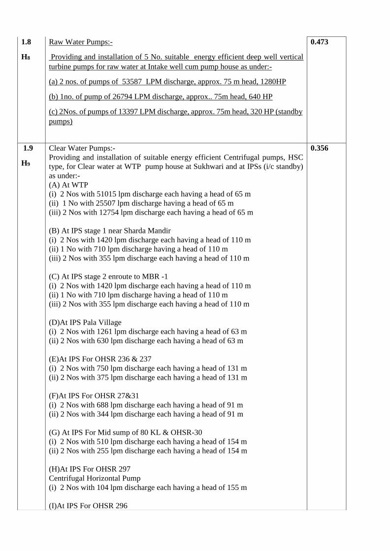
1.8
H8
Raw Water Pumps:-
Providing and installation of 5 No. suitable energy efficient deep well vertical
turbine pumps for raw water at Intake well cum pump house as under:-
(a) 2 nos. of pumps of 53587 LPM discharge, approx. 75 m head, 1280HP
(b) 1no. of pump of 26794 LPM discharge, approx.. 75m head, 640 HP
(c) 2Nos. of pumps of 13397 LPM discharge, approx. 75m head, 320 HP (standby
pumps)
0.473
1.9
H9
Clear Water Pumps:-
Providing and installation of suitable energy efficient Centrifugal pumps, HSC
type, for Clear water at WTP pump house at Sukhwari and at IPSs (i/c standby)
as under:-
(A) At WTP
(i) 2 Nos with 51015 lpm discharge each having a head of 65 m
(ii) 1 No with 25507 lpm discharge having a head of 65 m
(iii) 2 Nos with 12754 lpm discharge each having a head of 65 m
(B) At IPS stage 1 near Sharda Mandir
(i) 2 Nos with 1420 lpm discharge each having a head of 110 m
(ii) 1 No with 710 lpm discharge having a head of 110 m
(iii) 2 Nos with 355 lpm discharge each having a head of 110 m
(C) At IPS stage 2 enroute to MBR -1
(i) 2 Nos with 1420 lpm discharge each having a head of 110 m
(ii) 1 No with 710 lpm discharge having a head of 110 m
(iii) 2 Nos with 355 lpm discharge each having a head of 110 m
(D)At IPS Pala Village
(i) 2 Nos with 1261 lpm discharge each having a head of 63 m
(ii) 2 Nos with 630 lpm discharge each having a head of 63 m
(E)At IPS For OHSR 236 & 237
(i) 2 Nos with 750 lpm discharge each having a head of 131 m
(ii) 2 Nos with 375 lpm discharge each having a head of 131 m
(F)At IPS For OHSR 27&31
(i) 2 Nos with 688 lpm discharge each having a head of 91 m
(ii) 2 Nos with 344 lpm discharge each having a head of 91 m
(G) At IPS For Mid sump of 80 KL & OHSR-30
(i) 2 Nos with 510 lpm discharge each having a head of 154 m
(ii) 2 Nos with 255 lpm discharge each having a head of 154 m
(H)At IPS For OHSR 297
Centrifugal Horizontal Pump
(i) 2 Nos with 104 lpm discharge each having a head of 155 m
(I)At IPS For OHSR 296
0.356
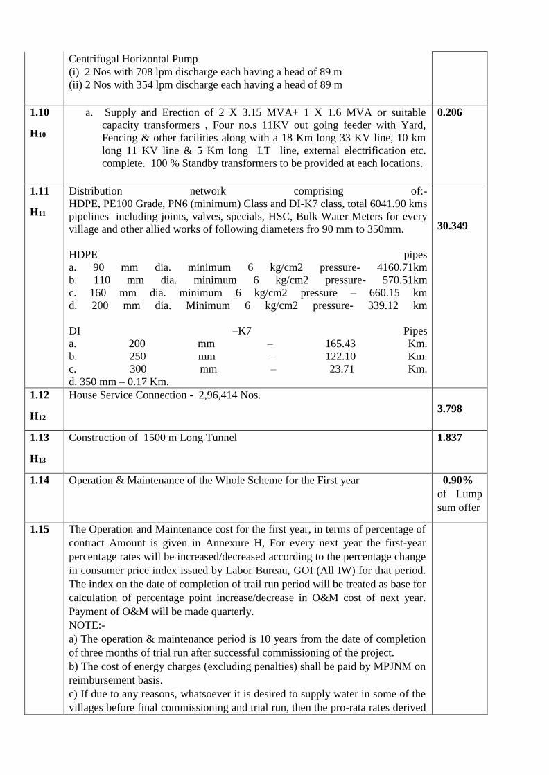
Centrifugal Horizontal Pump
(i) 2 Nos with 708 lpm discharge each having a head of 89 m
(ii) 2 Nos with 354 lpm discharge each having a head of 89 m
1.10
H10
a. Supply and Erection of 2 X 3.15 MVA+ 1 X 1.6 MVA or suitable
capacity transformers , Four no.s 11KV out going feeder with Yard,
Fencing & other facilities along with a 18 Km long 33 KV line, 10 km
long 11 KV line & 5 Km long LT line, external electrification etc.
complete. 100 % Standby transformers to be provided at each locations.
0.206
1.11
H11
Distribution network comprising of:-
HDPE, PE100 Grade, PN6 (minimum) Class and DI-K7 class, total 6041.90 kms
pipelines including joints, valves, specials, HSC, Bulk Water Meters for every
village and other allied works of following diameters fro 90 mm to 350mm.
HDPE pipes
a. 90 mm dia. minimum 6 kg/cm2 pressure- 4160.71km
b. 110 mm dia. minimum 6 kg/cm2 pressure- 570.51km
c. 160 mm dia. minimum 6 kg/cm2 pressure – 660.15 km
d. 200 mm dia. Minimum 6 kg/cm2 pressure- 339.12 km
DI –K7 Pipes
a. 200 mm – 165.43 Km.
b. 250 mm – 122.10 Km.
c. 300 mm – 23.71 Km.
d. 350 mm – 0.17 Km.
30.349
1.12
H12
House Service Connection - 2,96,414 Nos.
3.798
1.13
H13
Construction of 1500 m Long Tunnel 1.837
1.14 Operation & Maintenance of the Whole Scheme for the First year 0.90%
of Lump
sum offer
1.15 The Operation and Maintenance cost for the first year, in terms of percentage of
contract Amount is given in Annexure H, For every next year the first-year
percentage rates will be increased/decreased according to the percentage change
in consumer price index issued by Labor Bureau, GOI (All IW) for that period.
The index on the date of completion of trail run period will be treated as base for
calculation of percentage point increase/decrease in O&M cost of next year.
Payment of O&M will be made quarterly.
NOTE:-
a) The operation & maintenance period is 10 years from the date of completion
of three months of trial run after successful commissioning of the project.
b) The cost of energy charges (excluding penalties) shall be paid by MPJNM on
reimbursement basis.
c) If due to any reasons, whatsoever it is desired to supply water in some of the
villages before final commissioning and trial run, then the pro-rata rates derived
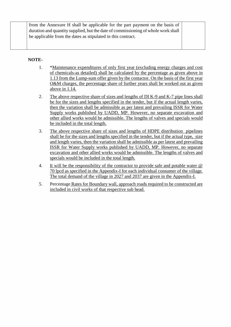
NOTE-
1. *Maintenance expenditures of only first year (excluding energy charges and cost
of chemicals-as detailed) shall be calculated by the percentage as given above in
1.13 from the Lump-sum offer given by the contactor. On the basis of the first year
O&M charges, the percentage share of further years shall be worked out as given
above in 1.14.
2. The above respective share of sizes and lengths of DI K-9 and K-7 pipe lines shall
be for the sizes and lengths specified in the tender, but if the actual length varies,
then the variation shall be admissible as per latest and prevailing ISSR for Water
Supply works published by UADD, MP. However, no separate excavation and
other allied works would be admissible. The lengths of valves and specials would
be included in the total length.
3. The above respective share of sizes and lengths of HDPE distribution pipelines
shall be for the sizes and lengths specified in the tender, but if the actual type, size
and length varies, then the variation shall be admissible as per latest and prevailing
ISSR for Water Supply works published by UADD, MP. However, no separate
excavation and other allied works would be admissible. The lengths of valves and
specials would be included in the total length.
4. It will be the responsibility of the contractor to provide safe and potable water @
70 lpcd as specified in the Appendix-I for each individual consumer of the village.
The total demand of the village in 2027 and 2037 are given in the Appendix-I.
5. Percentage Rates for Boundary wall, approach roads required to be constructed are
included in civil works of that respective sub head.
from the Annexure H shall be applicable for the part payment on the basis of
duration and quantity supplied, but the date of commissioning of whole work shall
be applicable from the dates as stipulated in this contract.
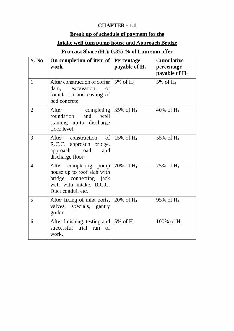
CHAPTER - 1.1
Break up of schedule of payment for the
Intake well cum pump house and Approach Bridge
Pro-rata Share (H1): 0.355 % of Lum sum offer
S. No On completion of item of
work
Percentage
payable of H1
Cumulative
percentage
payable of H1
1 After construction of coffer
dam, excavation of
foundation and casting of
bed concrete.
5% of H1 5% of H1
2 After completing
foundation and well
staining up-to discharge
floor level.
35% of H1 40% of H1
3 After construction of
R.C.C. approach bridge,
approach road and
discharge floor.
15% of H1 55% of H1
4 After completing pump
house up to roof slab with
bridge connecting jack
well with intake, R.C.C.
Duct conduit etc.
20% of H1 75% of H1
5 After fixing of inlet ports,
valves, specials, gantry
girder.
20% of H1 95% of H1
6 After finishing, testing and
successful trial run of
work.
5% of H1 100% of H1
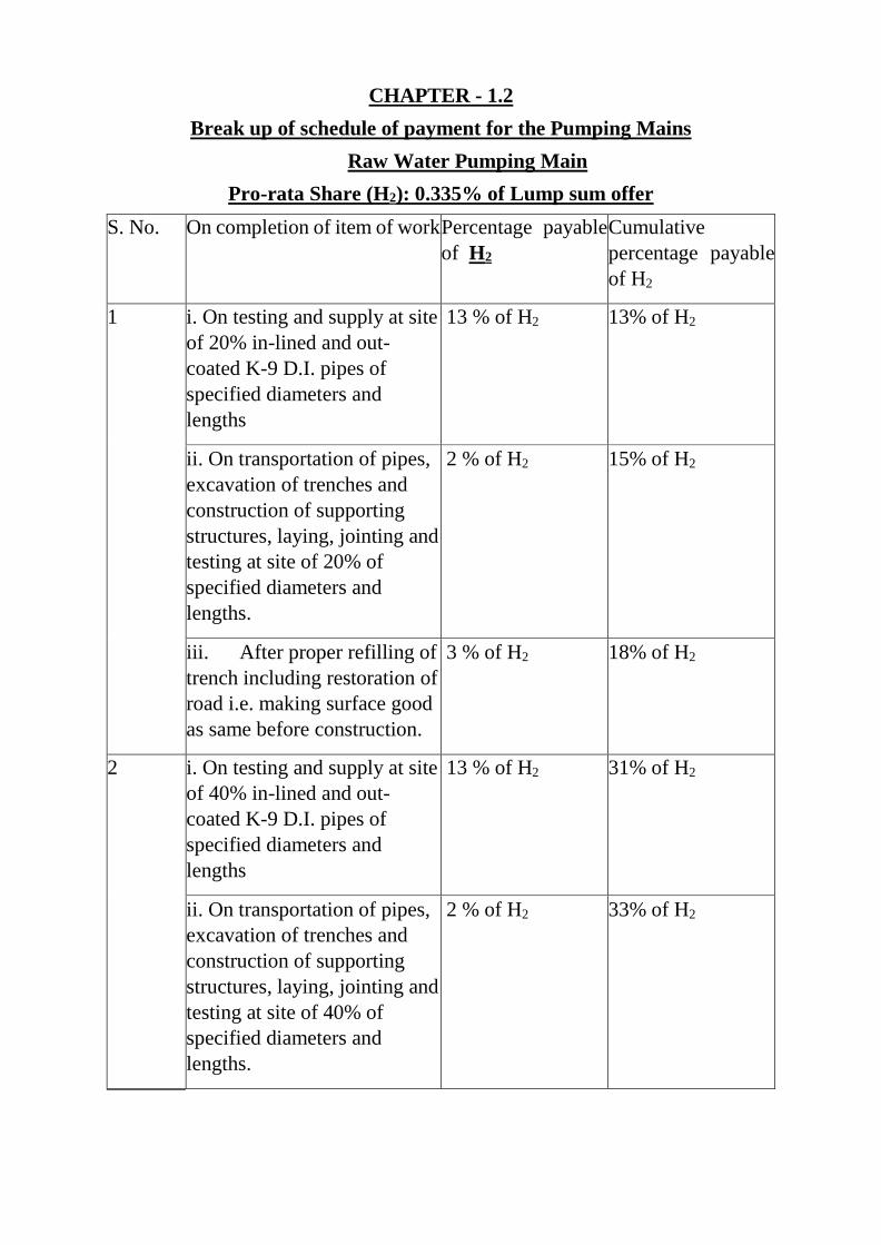
CHAPTER - 1.2
Break up of schedule of payment for the Pumping Mains
Raw Water Pumping Main
Pro-rata Share (H2): 0.335% of Lump sum offer
S. No. On completion of item of work Percentage payable
of H2
Cumulative
percentage payable
of H2
1 i. On testing and supply at site
of 20% in-lined and out-
coated K-9 D.I. pipes of
specified diameters and
lengths
13 % of H2 13% of H2
ii. On transportation of pipes,
excavation of trenches and
construction of supporting
structures, laying, jointing and
testing at site of 20% of
specified diameters and
lengths.
2 % of H2 15% of H2
iii. After proper refilling of
trench including restoration of
road i.e. making surface good
as same before construction.
3 % of H2 18% of H2
2 i. On testing and supply at site
of 40% in-lined and out-
coated K-9 D.I. pipes of
specified diameters and
lengths
13 % of H2 31% of H2
ii. On transportation of pipes,
excavation of trenches and
construction of supporting
structures, laying, jointing and
testing at site of 40% of
specified diameters and
lengths.
2 % of H2 33% of H2
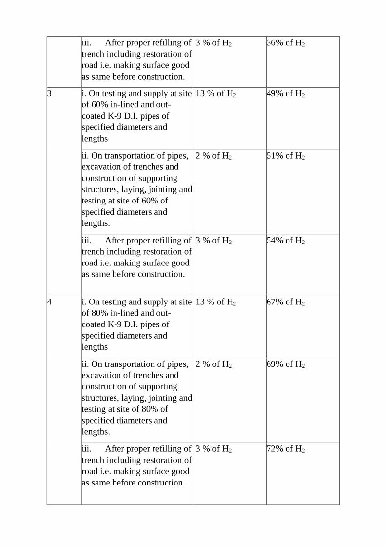
iii. After proper refilling of
trench including restoration of
road i.e. making surface good
as same before construction.
3 % of H2 36% of H2
3 i. On testing and supply at site
of 60% in-lined and out-
coated K-9 D.I. pipes of
specified diameters and
lengths
13 % of H2 49% of H2
ii. On transportation of pipes,
excavation of trenches and
construction of supporting
structures, laying, jointing and
testing at site of 60% of
specified diameters and
lengths.
2 % of H2 51% of H2
iii. After proper refilling of
trench including restoration of
road i.e. making surface good
as same before construction.
3 % of H2 54% of H2
4 i. On testing and supply at site
of 80% in-lined and out-
coated K-9 D.I. pipes of
specified diameters and
lengths
13 % of H2 67% of H2
ii. On transportation of pipes,
excavation of trenches and
construction of supporting
structures, laying, jointing and
testing at site of 80% of
specified diameters and
lengths.
2 % of H2 69% of H2
iii. After proper refilling of
trench including restoration of
road i.e. making surface good
as same before construction.
3 % of H2 72% of H2
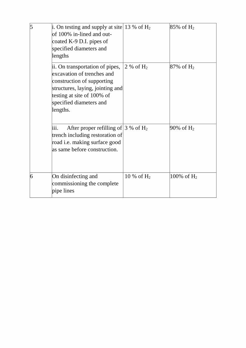
5 i. On testing and supply at site
of 100% in-lined and out-
coated K-9 D.I. pipes of
specified diameters and
lengths
13 % of H2 85% of H2
ii. On transportation of pipes,
excavation of trenches and
construction of supporting
structures, laying, jointing and
testing at site of 100% of
specified diameters and
lengths.
2 % of H2 87% of H2
iii. After proper refilling of
trench including restoration of
road i.e. making surface good
as same before construction.
3 % of H2 90% of H2
6 On disinfecting and
commissioning the complete
pipe lines
10 % of H2 100% of H2
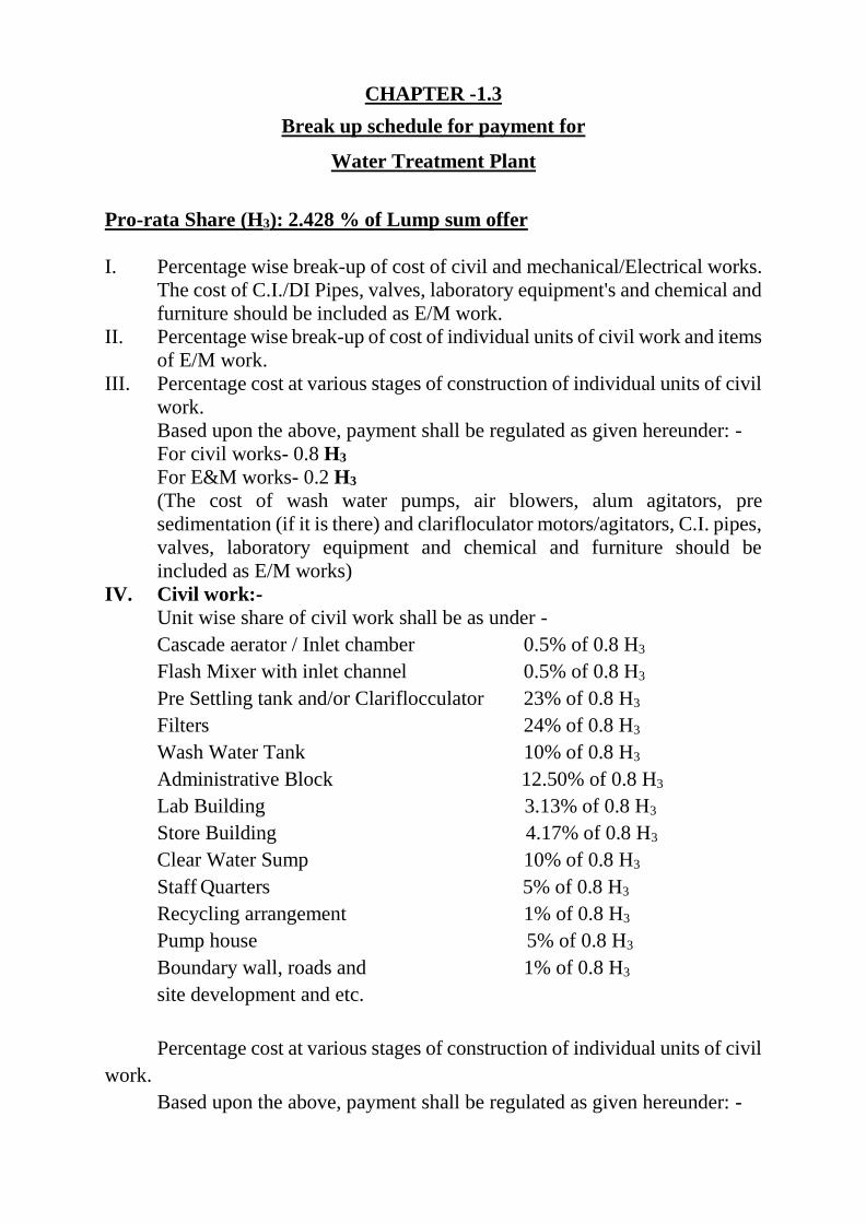
CHAPTER -1.3
Break up schedule for payment for
Water Treatment Plant
Pro-rata Share (H3): 2.428 % of Lump sum offer
I. Percentage wise break-up of cost of civil and mechanical/Electrical works.
The cost of C.I./DI Pipes, valves, laboratory equipment's and chemical and
furniture should be included as E/M work.
II. Percentage wise break-up of cost of individual units of civil work and items
of E/M work.
III. Percentage cost at various stages of construction of individual units of civil
work.
Based upon the above, payment shall be regulated as given hereunder: -
For civil works- 0.8 H3
For E&M works- 0.2 H3
(The cost of wash water pumps, air blowers, alum agitators, pre
sedimentation (if it is there) and clarifloculator motors/agitators, C.I. pipes,
valves, laboratory equipment and chemical and furniture should be
included as E/M works)
IV. Civil work:-
Unit wise share of civil work shall be as under -
Cascade aerator / Inlet chamber 0.5% of 0.8 H3
Flash Mixer with inlet channel 0.5% of 0.8 H3
Pre Settling tank and/or Clariflocculator 23% of 0.8 H3
Filters 24% of 0.8 H3
Wash Water Tank 10% of 0.8 H3
Administrative Block 12.50% of 0.8 H3
Lab Building 3.13% of 0.8 H3
Store Building 4.17% of 0.8 H3
Clear Water Sump 10% of 0.8 H3
Staff Quarters 5% of 0.8 H3
Recycling arrangement 1% of 0.8 H3
Pump house 5% of 0.8 H3
Boundary wall, roads and 1% of 0.8 H3
site development and etc.
Percentage cost at various stages of construction of individual units of civil
work.
Based upon the above, payment shall be regulated as given hereunder: -
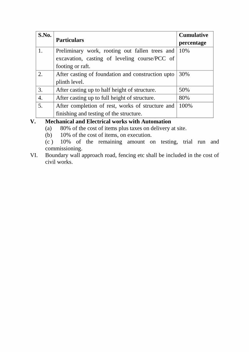
S.No. Particulars
Cumulative
percentage
1. Preliminary work, rooting out fallen trees and
excavation, casting of leveling course/PCC of
footing or raft.
10%
2. After casting of foundation and construction upto
plinth level.
30%
3. After casting up to half height of structure. 50%
4. After casting up to full height of structure. 80%
5. After completion of rest, works of structure and
finishing and testing of the structure.
100%
V. Mechanical and Electrical works with Automation
(a) 80% of the cost of items plus taxes on delivery at site.
(b) 10% of the cost of items, on execution.
(c ) 10% of the remaining amount on testing, trial run and
commissioning.
VI. Boundary wall approach road, fencing etc shall be included in the cost of
civil works.
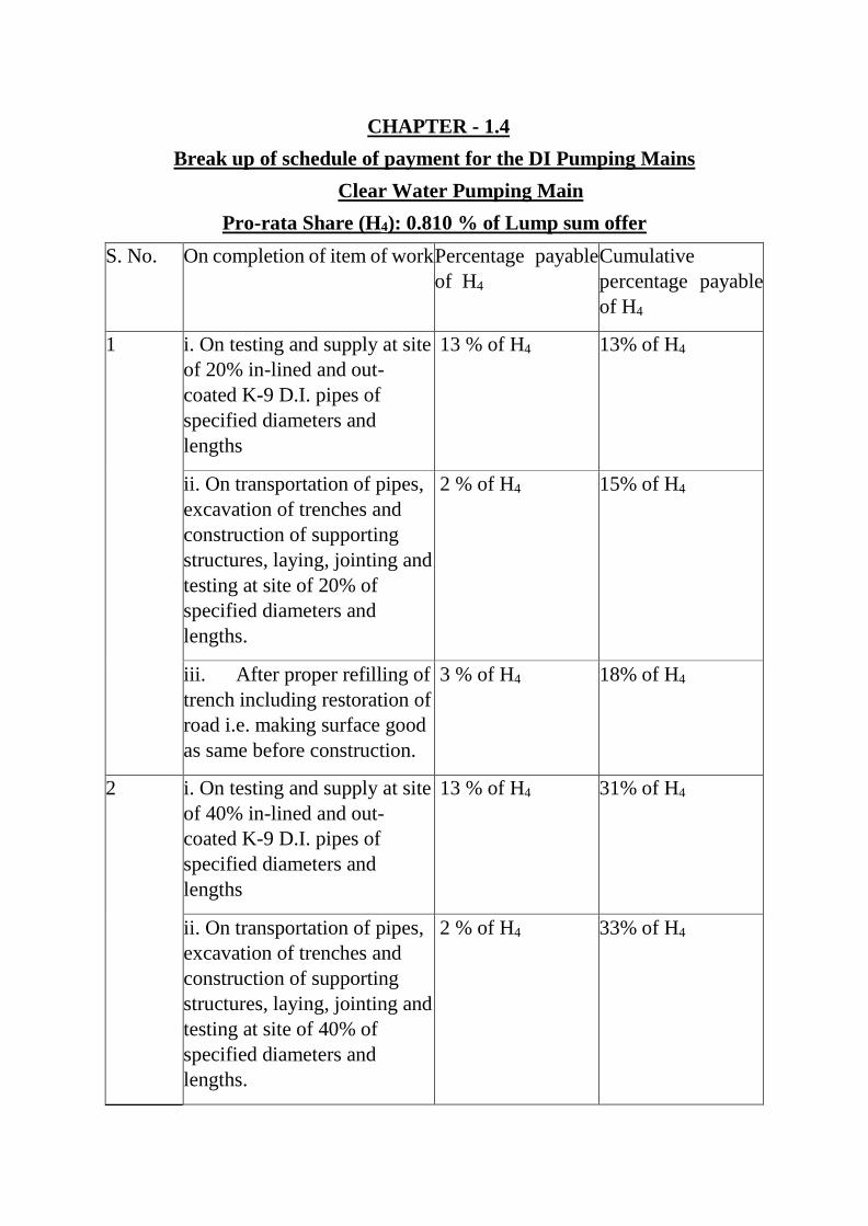
CHAPTER - 1.4
Break up of schedule of payment for the DI Pumping Mains
Clear Water Pumping Main
Pro-rata Share (H4): 0.810 % of Lump sum offer
S. No. On completion of item of work Percentage payable
of H4
Cumulative
percentage payable
of H4
1 i. On testing and supply at site
of 20% in-lined and out-
coated K-9 D.I. pipes of
specified diameters and
lengths
13 % of H4 13% of H4
ii. On transportation of pipes,
excavation of trenches and
construction of supporting
structures, laying, jointing and
testing at site of 20% of
specified diameters and
lengths.
2 % of H4 15% of H4
iii. After proper refilling of
trench including restoration of
road i.e. making surface good
as same before construction.
3 % of H4 18% of H4
2 i. On testing and supply at site
of 40% in-lined and out-
coated K-9 D.I. pipes of
specified diameters and
lengths
13 % of H4 31% of H4
ii. On transportation of pipes,
excavation of trenches and
construction of supporting
structures, laying, jointing and
testing at site of 40% of
specified diameters and
lengths.
2 % of H4 33% of H4
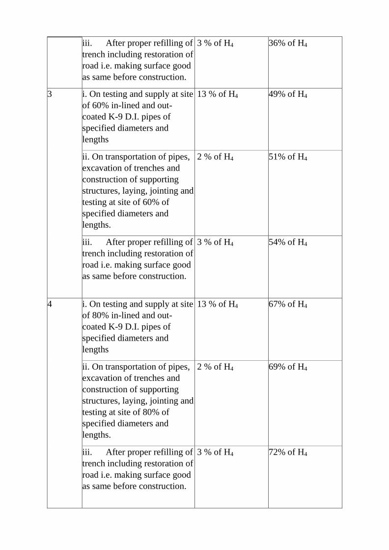
iii. After proper refilling of
trench including restoration of
road i.e. making surface good
as same before construction.
3 % of H4 36% of H4
3 i. On testing and supply at site
of 60% in-lined and out-
coated K-9 D.I. pipes of
specified diameters and
lengths
13 % of H4 49% of H4
ii. On transportation of pipes,
excavation of trenches and
construction of supporting
structures, laying, jointing and
testing at site of 60% of
specified diameters and
lengths.
2 % of H4 51% of H4
iii. After proper refilling of
trench including restoration of
road i.e. making surface good
as same before construction.
3 % of H4 54% of H4
4 i. On testing and supply at site
of 80% in-lined and out-
coated K-9 D.I. pipes of
specified diameters and
lengths
13 % of H4 67% of H4
ii. On transportation of pipes,
excavation of trenches and
construction of supporting
structures, laying, jointing and
testing at site of 80% of
specified diameters and
lengths.
2 % of H4 69% of H4
iii. After proper refilling of
trench including restoration of
road i.e. making surface good
as same before construction.
3 % of H4 72% of H4
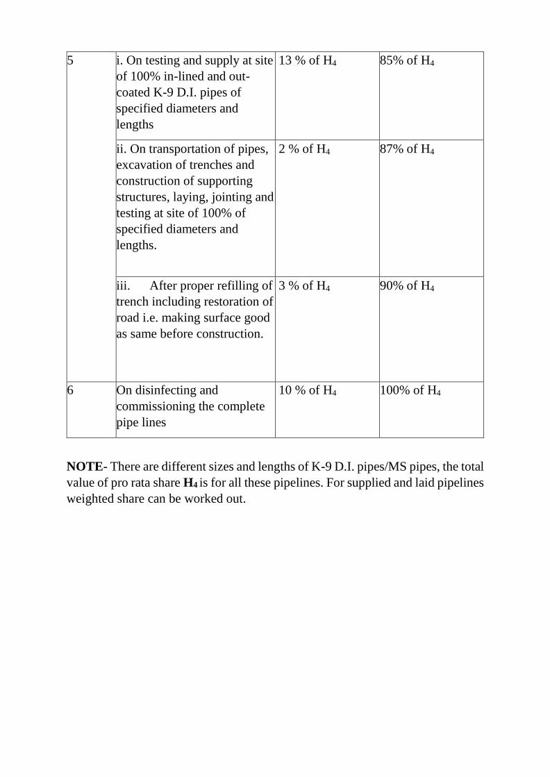
5 i. On testing and supply at site
of 100% in-lined and out-
coated K-9 D.I. pipes of
specified diameters and
lengths
13 % of H4 85% of H4
ii. On transportation of pipes,
excavation of trenches and
construction of supporting
structures, laying, jointing and
testing at site of 100% of
specified diameters and
lengths.
2 % of H4 87% of H4
iii. After proper refilling of
trench including restoration of
road i.e. making surface good
as same before construction.
3 % of H4 90% of H4
6 On disinfecting and
commissioning the complete
pipe lines
10 % of H4 100% of H4
NOTE- There are different sizes and lengths of K-9 D.I. pipes/MS pipes, the total
value of pro rata share H4 is for all these pipelines. For supplied and laid pipelines
weighted share can be worked out.
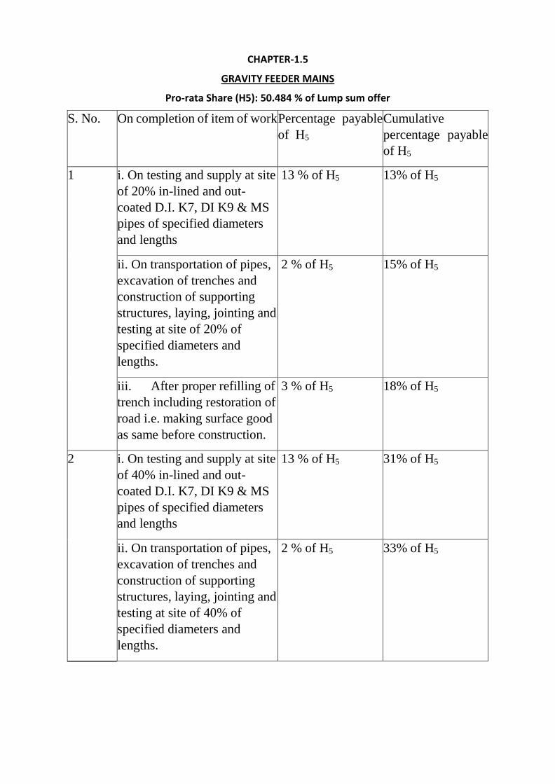
CHAPTER-1.5
GRAVITY FEEDER MAINS
Pro-rata Share (H5): 50.484 % of Lump sum offer
S. No. On completion of item of work Percentage payable
of H5
Cumulative
percentage payable
of H5
1 i. On testing and supply at site
of 20% in-lined and out-
coated D.I. K7, DI K9 & MS
pipes of specified diameters
and lengths
13 % of H5 13% of H5
ii. On transportation of pipes,
excavation of trenches and
construction of supporting
structures, laying, jointing and
testing at site of 20% of
specified diameters and
lengths.
2 % of H5 15% of H5
iii. After proper refilling of
trench including restoration of
road i.e. making surface good
as same before construction.
3 % of H5 18% of H5
2 i. On testing and supply at site
of 40% in-lined and out-
coated D.I. K7, DI K9 & MS
pipes of specified diameters
and lengths
13 % of H5 31% of H5
ii. On transportation of pipes,
excavation of trenches and
construction of supporting
structures, laying, jointing and
testing at site of 40% of
specified diameters and
lengths.
2 % of H5 33% of H5
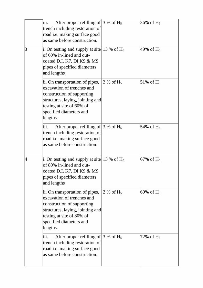
iii. After proper refilling of
trench including restoration of
road i.e. making surface good
as same before construction.
3 % of H5 36% of H5
3 i. On testing and supply at site
of 60% in-lined and out-
coated D.I. K7, DI K9 & MS
pipes of specified diameters
and lengths
13 % of H5 49% of H5
ii. On transportation of pipes,
excavation of trenches and
construction of supporting
structures, laying, jointing and
testing at site of 60% of
specified diameters and
lengths.
2 % of H5 51% of H5
iii. After proper refilling of
trench including restoration of
road i.e. making surface good
as same before construction.
3 % of H5 54% of H5
4 i. On testing and supply at site
of 80% in-lined and out-
coated D.I. K7, DI K9 & MS
pipes of specified diameters
and lengths
13 % of H5 67% of H5
ii. On transportation of pipes,
excavation of trenches and
construction of supporting
structures, laying, jointing and
testing at site of 80% of
specified diameters and
lengths.
2 % of H5 69% of H5
iii. After proper refilling of
trench including restoration of
road i.e. making surface good
as same before construction.
3 % of H5 72% of H5
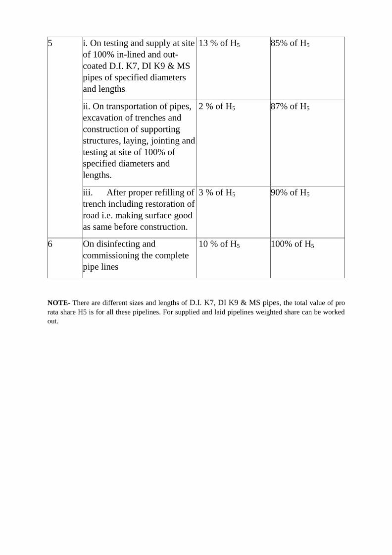
5 i. On testing and supply at site
of 100% in-lined and out-
coated D.I. K7, DI K9 & MS
pipes of specified diameters
and lengths
13 % of H5 85% of H5
ii. On transportation of pipes,
excavation of trenches and
construction of supporting
structures, laying, jointing and
testing at site of 100% of
specified diameters and
lengths.
2 % of H5 87% of H5
iii. After proper refilling of
trench including restoration of
road i.e. making surface good
as same before construction.
3 % of H5 90% of H5
6 On disinfecting and
commissioning the complete
pipe lines
10 % of H5 100% of H5
NOTE- There are different sizes and lengths of D.I. K7, DI K9 & MS pipes, the total value of pro
rata share H5 is for all these pipelines. For supplied and laid pipelines weighted share can be worked
out.
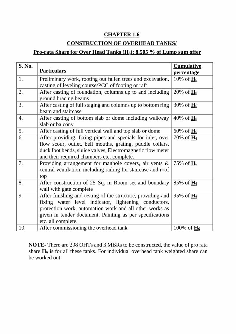
CHAPTER 1.6
CONSTRUCTION OF OVERHEAD TANKS/
Pro-rata Share for Over Head Tanks (H6): 8.505 % of Lump sum offer
S. No. Particulars
Cumulative
percentage
1. Preliminary work, rooting out fallen trees and excavation,
casting of leveling course/PCC of footing or raft
10% of H6
2. After casting of foundation, columns up to and including
ground bracing beams
20% of H6
3. After casting of full staging and columns up to bottom ring
beam and staircase
30% of H6
4. After casting of bottom slab or dome including walkway
slab or balcony
40% of H6
5. After casting of full vertical wall and top slab or dome 60% of H6
6. After providing, fixing pipes and specials for inlet, over
flow scour, outlet, bell mouths, grating, puddle collars,
duck foot bends, sluice valves, Electromagnetic flow meter
and their required chambers etc. complete.
70% of H6
7. Providing arrangement for manhole covers, air vents &
central ventilation, including railing for staircase and roof
top
75% of H6
8. After construction of 25 Sq. m Room set and boundary
wall with gate complete
85% of H6
9. After finishing and testing of the structure, providing and
fixing water level indicator, lightening conductors,
protection work, automation work and all other works as
given in tender document. Painting as per specifications
etc. all complete.
95% of H6
10. After commissioning the overhead tank 100% of H6
NOTE- There are 298 OHTs and 3 MBRs to be constructed, the value of pro rata
share H6 is for all these tanks. For individual overhead tank weighted share can
be worked out.
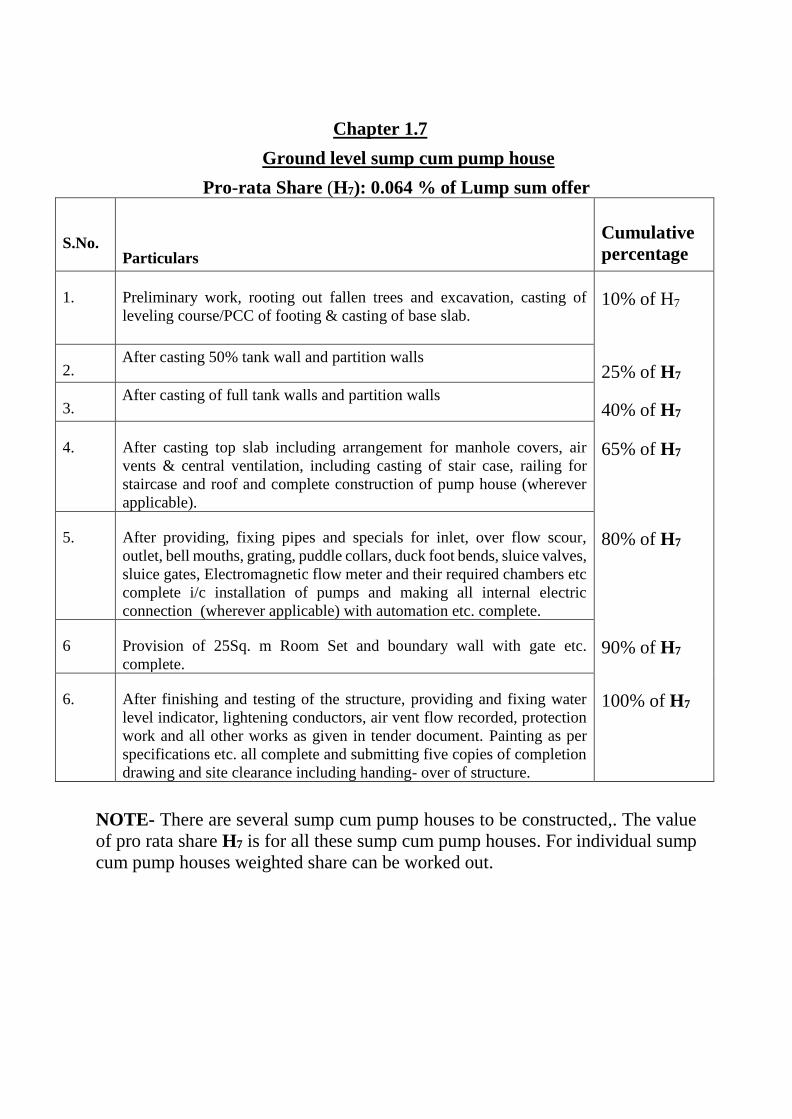
Chapter 1.7
Ground level sump cum pump house
Pro-rata Share (H7): 0.064 % of Lump sum offer
S.No.
Particulars
Cumulative
percentage
1. Preliminary work, rooting out fallen trees and excavation, casting of
leveling course/PCC of footing & casting of base slab. 10% of H7
2. After casting 50% tank wall and partition walls
25% of H7
3. After casting of full tank walls and partition walls
40% of H7
4. After casting top slab including arrangement for manhole covers, air
vents & central ventilation, including casting of stair case, railing for
staircase and roof and complete construction of pump house (wherever
applicable).
65% of H7
5. After providing, fixing pipes and specials for inlet, over flow scour,
outlet, bell mouths, grating, puddle collars, duck foot bends, sluice valves,
sluice gates, Electromagnetic flow meter and their required chambers etc
complete i/c installation of pumps and making all internal electric
connection (wherever applicable) with automation etc. complete.
80% of H7
6 Provision of 25Sq. m Room Set and boundary wall with gate etc.
complete. 90% of H7
6. After finishing and testing of the structure, providing and fixing water
level indicator, lightening conductors, air vent flow recorded, protection
work and all other works as given in tender document. Painting as per
specifications etc. all complete and submitting five copies of completion
drawing and site clearance including handing- over of structure.
100% of H7
NOTE- There are several sump cum pump houses to be constructed,. The value
of pro rata share H7 is for all these sump cum pump houses. For individual sump
cum pump houses weighted share can be worked out.
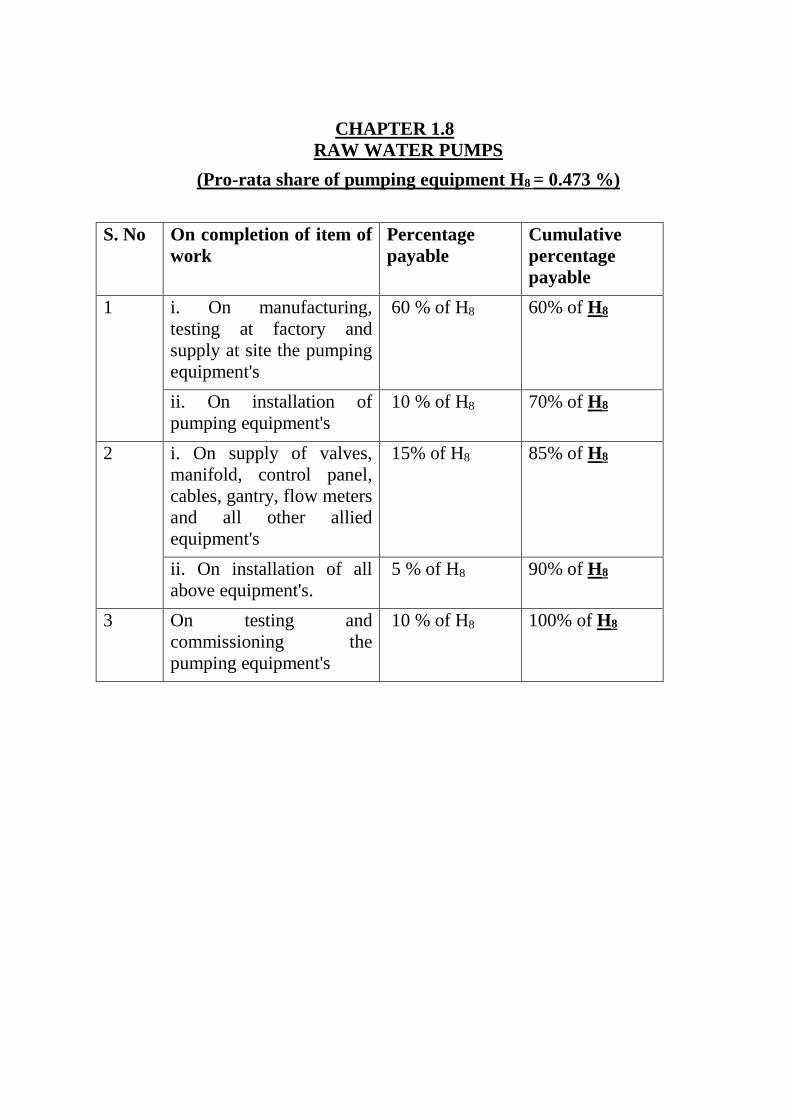
CHAPTER 1.8
RAW WATER PUMPS
(Pro-rata share of pumping equipment H8 = 0.473 %)
S. No On completion of item of
work
Percentage
payable
Cumulative
percentage
payable
1 i. On manufacturing,
testing at factory and
supply at site the pumping
equipment's
60 % of H8 60% of H8
ii. On installation of
pumping equipment's
10 % of H8 70% of H8
2 i. On supply of valves,
manifold, control panel,
cables, gantry, flow meters
and all other allied
equipment's
15% of H8 85% of H8
ii. On installation of all
above equipment's.
5 % of H8 90% of H8
3 On testing and
commissioning the
pumping equipment's
10 % of H8 100% of H8
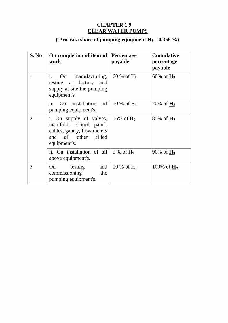
CHAPTER 1.9
CLEAR WATER PUMPS
( Pro-rata share of pumping equipment H9 = 0.356 %)
S. No On completion of item of
work
Percentage
payable
Cumulative
percentage
payable
1 i. On manufacturing,
testing at factory and
supply at site the pumping
equipment's
60 % of H9 60% of H9
ii. On installation of
pumping equipment's.
10 % of H9 70% of H9
2 i. On supply of valves,
manifold, control panel,
cables, gantry, flow meters
and all other allied
equipment's.
15% of H9 85% of H9
ii. On installation of all
above equipment's.
5 % of H9 90% of H9
3 On testing and
commissioning the
pumping equipment's.
10 % of H9 100% of H9
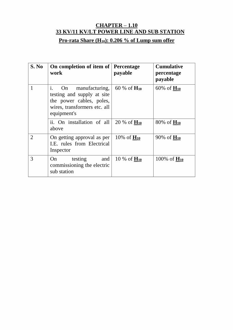
CHAPTER – 1.10
33 KV/11 KV/LT POWER LINE AND SUB STATION
Pro-rata Share (H10): 0.206 % of Lump sum offer
S. No On completion of item of
work
Percentage
payable
Cumulative
percentage
payable
1 i. On manufacturing,
testing and supply at site
the power cables, poles,
wires, transformers etc. all
equipment's
60 % of H10 60% of H10
ii. On installation of all
above
20 % of H10 80% of H10
2 On getting approval as per
I.E. rules from Electrical
Inspector
10% of H10 90% of H10
3 On testing and
commissioning the electric
sub station
10 % of H10 100% of H10
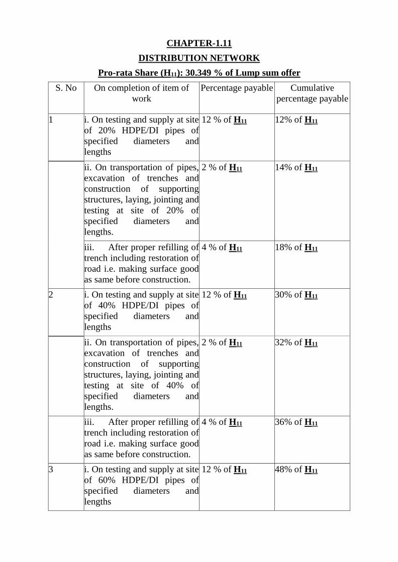
CHAPTER-1.11
DISTRIBUTION NETWORK
Pro-rata Share (H11): 30.349 % of Lump sum offer
S. No On completion of item of
work
Percentage payable Cumulative
percentage payable
1 i. On testing and supply at site
of 20% HDPE/DI pipes of
specified diameters and
lengths
12 % of H11 12% of H11
ii. On transportation of pipes,
excavation of trenches and
construction of supporting
structures, laying, jointing and
testing at site of 20% of
specified diameters and
lengths.
2 % of H11 14% of H11
iii. After proper refilling of
trench including restoration of
road i.e. making surface good
as same before construction.
4 % of H11 18% of H11
2 i. On testing and supply at site
of 40% HDPE/DI pipes of
specified diameters and
lengths
12 % of H11 30% of H11
ii. On transportation of pipes,
excavation of trenches and
construction of supporting
structures, laying, jointing and
testing at site of 40% of
specified diameters and
lengths.
2 % of H11 32% of H11
iii. After proper refilling of
trench including restoration of
road i.e. making surface good
as same before construction.
4 % of H11 36% of H11
3 i. On testing and supply at site
of 60% HDPE/DI pipes of
specified diameters and
lengths
12 % of H11 48% of H11
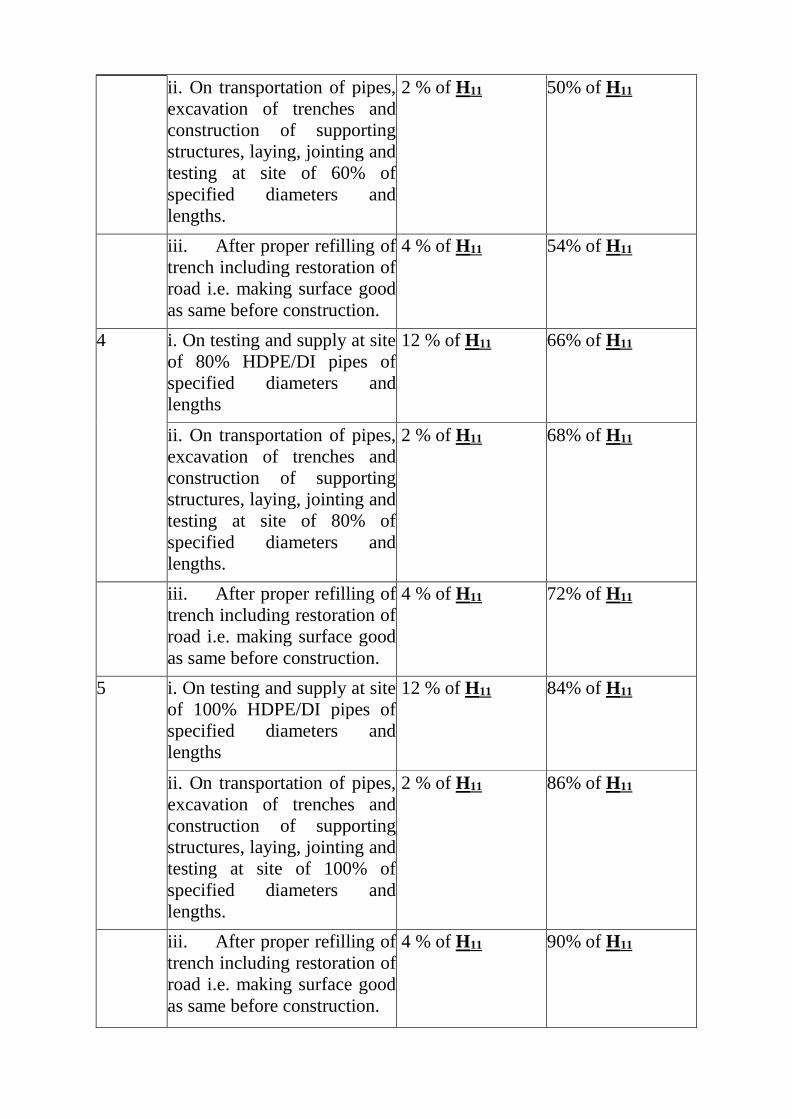
ii. On transportation of pipes,
excavation of trenches and
construction of supporting
structures, laying, jointing and
testing at site of 60% of
specified diameters and
lengths.
2 % of H11 50% of H11
iii. After proper refilling of
trench including restoration of
road i.e. making surface good
as same before construction.
4 % of H11 54% of H11
4 i. On testing and supply at site
of 80% HDPE/DI pipes of
specified diameters and
lengths
12 % of H11 66% of H11
ii. On transportation of pipes,
excavation of trenches and
construction of supporting
structures, laying, jointing and
testing at site of 80% of
specified diameters and
lengths.
2 % of H11 68% of H11
iii. After proper refilling of
trench including restoration of
road i.e. making surface good
as same before construction.
4 % of H11 72% of H11
5 i. On testing and supply at site
of 100% HDPE/DI pipes of
specified diameters and
lengths
12 % of H11 84% of H11
ii. On transportation of pipes,
excavation of trenches and
construction of supporting
structures, laying, jointing and
testing at site of 100% of
specified diameters and
lengths.
2 % of H11 86% of H11
iii. After proper refilling of
trench including restoration of
road i.e. making surface good
as same before construction.
4 % of H11 90% of H11

7 On disinfecting and
commissioning the complete
pipe lines
10 % of H11 100% of H11
NOTE- There are different sizes and lengths of HDPE and DI pipes, the total
value of pro rata share H11 is for all these pipelines. For supplied and laid pipelines
weighted share can be worked out.
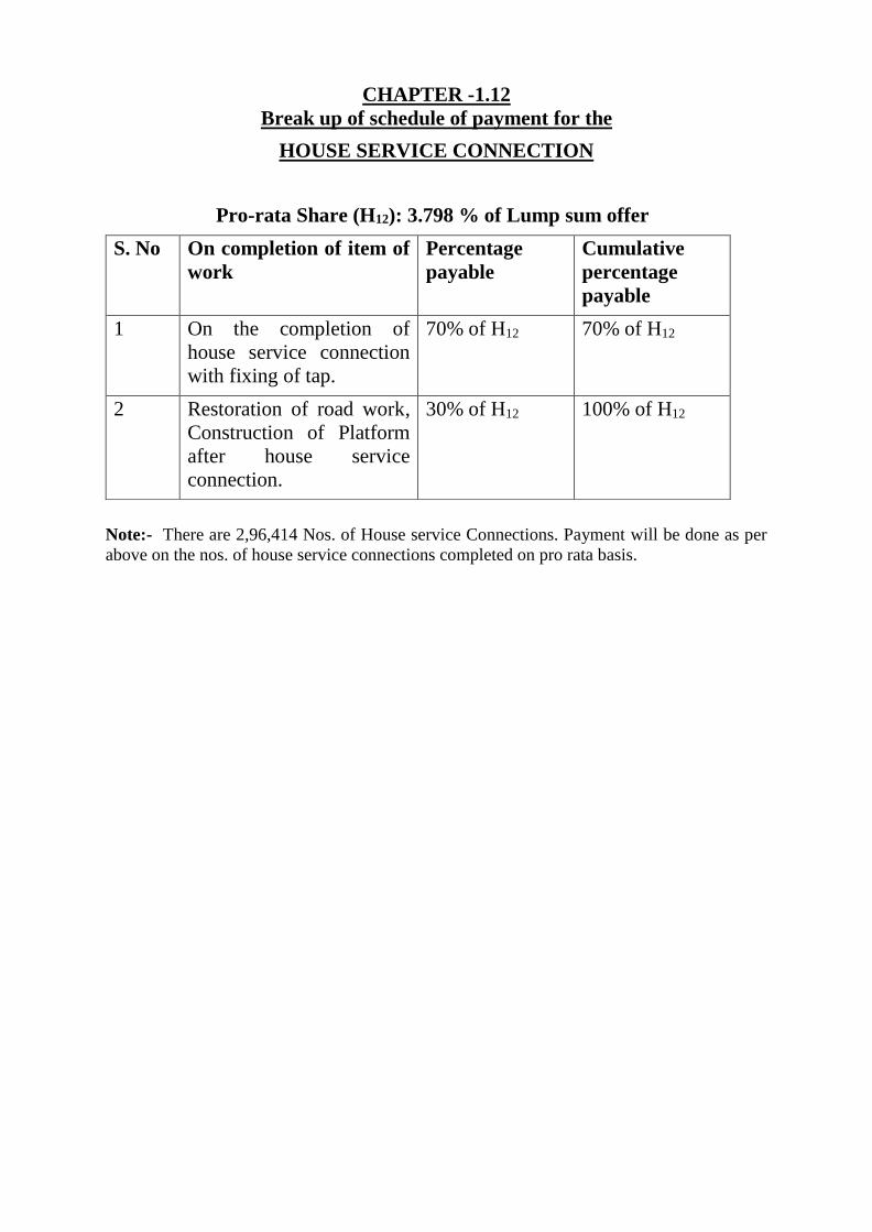
CHAPTER -1.12
Break up of schedule of payment for the
HOUSE SERVICE CONNECTION
Pro-rata Share (H12): 3.798 % of Lump sum offer
S. No On completion of item of
work
Percentage
payable
Cumulative
percentage
payable
1 On the completion of
house service connection
with fixing of tap.
70% of H12 70% of H12
2 Restoration of road work,
Construction of Platform
after house service
connection.
30% of H12 100% of H12
Note:- There are 2,96,414 Nos. of House service Connections. Payment will be done as per
above on the nos. of house service connections completed on pro rata basis.
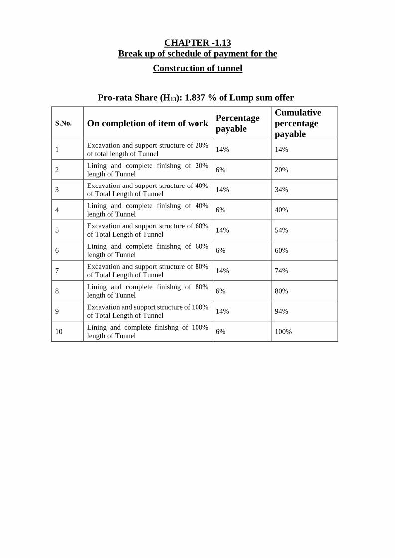
CHAPTER -1.13
Break up of schedule of payment for the
Construction of tunnel
Pro-rata Share (H13): 1.837 % of Lump sum offer
S.No. On completion of item of work Percentage
payable
Cumulative
percentage
payable
1 Excavation and support structure of 20%
of total length of Tunnel 14% 14%
2 Lining and complete finishng of 20%
length of Tunnel 6% 20%
3 Excavation and support structure of 40%
of Total Length of Tunnel 14% 34%
4 Lining and complete finishng of 40%
length of Tunnel 6% 40%
5 Excavation and support structure of 60%
of Total Length of Tunnel 14% 54%
6 Lining and complete finishng of 60%
length of Tunnel 6% 60%
7 Excavation and support structure of 80%
of Total Length of Tunnel 14% 74%
8 Lining and complete finishng of 80%
length of Tunnel 6% 80%
9 Excavation and support structure of 100%
of Total Length of Tunnel 14% 94%
10 Lining and complete finishng of 100%
length of Tunnel 6% 100%
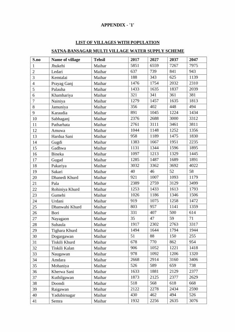
APPENDIX - '1'
LIST OF VILLAGES WITH POPULATION
SATNA-BANSAGAR MULTI VILLAGE WATER SUPPLY SCHEME
S.no Name of village Tehsil 2017 2027 2037 2047
1 Jhukehi Maihar 5851 6559 7267 7975
2 Ledari Maihar 637 739 841 943
3 Kemtalai Maihar 188 343 625 1139
4 Prayag Ganj Maihar 1476 1754 2032 2310
5 Palauha Maihar 1433 1635 1837 2039
6 Khamhariya Maihar 321 341 361 381
7 Nainiya Maihar 1279 1457 1635 1813
8 Jamuniya Maihar 356 402 448 494
9 Karaudia Maihar 891 1045 1224 1434
10 Sabhaganj Maihar 2376 2688 3000 3312
11 Patharhata Maihar 2761 3111 3461 3811
12 Amuwa Maihar 1044 1148 1252 1356
13 Hardua Sani Maihar 958 1189 1475 1830
14 Gugdi Maihar 1383 1667 1951 2235
15 Gadhwa Maihar 1131 1344 1596 1895
16 Bineka Maihar 1097 1213 1329 1445
17 Gugad Maihar 1285 1487 1689 1891
18 Pakariya Maihar 3032 3362 3692 4022
19 Sakari Maihar 40 46 52 58
20 Dhanedi Khurd Maihar 921 1007 1093 1179
21 Pala Maihar 2389 2759 3129 3499
22 Rohiniya Khurd Maihar 1253 1433 1613 1793
23 Gumehi Maihar 1026 1186 1346 1506
24 Urdani Maihar 919 1075 1258 1472
25 Dhanwahi Khurd Maihar 803 957 1141 1359
26 Bori Maihar 331 407 500 614
27 Nayagaon Maihar 35 47 59 71
28 Suhaula Maihar 1917 2302 2763 3317
29 Tighara Khurd Maihar 1494 1644 1794 1944
30 Dogargawan Maihar 51 88 150 255
31 Tiskili Khurd Maihar 678 770 862 954
32 Tiskili Kalan Maihar 906 1052 1221 1418
33 Naugawan Maihar 978 1092 1206 1320
34 Amdara Maihar 2668 2914 3160 3406
35 Mohaniya Maihar 526 589 659 738
36 Kherwa Sani Maihar 1633 1881 2129 2377
37 Kuthilgawan Maihar 1873 2125 2377 2629
38 Doondi Maihar 518 568 618 668
39 Raigawan Maihar 2122 2278 2434 2590
40 Yadubirnagar Maihar 430 462 494 526
41 Semra Maihar 1932 2256 2635 3076
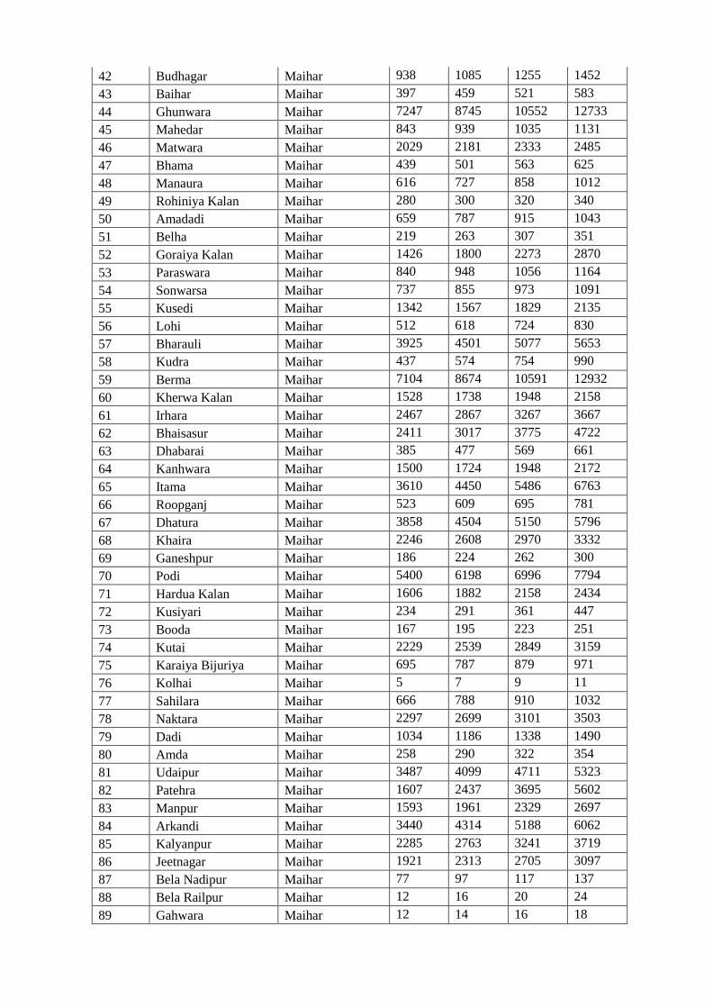
42 Budhagar Maihar 938 1085 1255 1452
43 Baihar Maihar 397 459 521 583
44 Ghunwara Maihar 7247 8745 10552 12733
45 Mahedar Maihar 843 939 1035 1131
46 Matwara Maihar 2029 2181 2333 2485
47 Bhama Maihar 439 501 563 625
48 Manaura Maihar 616 727 858 1012
49 Rohiniya Kalan Maihar 280 300 320 340
50 Amadadi Maihar 659 787 915 1043
51 Belha Maihar 219 263 307 351
52 Goraiya Kalan Maihar 1426 1800 2273 2870
53 Paraswara Maihar 840 948 1056 1164
54 Sonwarsa Maihar 737 855 973 1091
55 Kusedi Maihar 1342 1567 1829 2135
56 Lohi Maihar 512 618 724 830
57 Bharauli Maihar 3925 4501 5077 5653
58 Kudra Maihar 437 574 754 990
59 Berma Maihar 7104 8674 10591 12932
60 Kherwa Kalan Maihar 1528 1738 1948 2158
61 Irhara Maihar 2467 2867 3267 3667
62 Bhaisasur Maihar 2411 3017 3775 4722
63 Dhabarai Maihar 385 477 569 661
64 Kanhwara Maihar 1500 1724 1948 2172
65 Itama Maihar 3610 4450 5486 6763
66 Roopganj Maihar 523 609 695 781
67 Dhatura Maihar 3858 4504 5150 5796
68 Khaira Maihar 2246 2608 2970 3332
69 Ganeshpur Maihar 186 224 262 300
70 Podi Maihar 5400 6198 6996 7794
71 Hardua Kalan Maihar 1606 1882 2158 2434
72 Kusiyari Maihar 234 291 361 447
73 Booda Maihar 167 195 223 251
74 Kutai Maihar 2229 2539 2849 3159
75 Karaiya Bijuriya Maihar 695 787 879 971
76 Kolhai Maihar 5 7 9 11
77 Sahilara Maihar 666 788 910 1032
78 Naktara Maihar 2297 2699 3101 3503
79 Dadi Maihar 1034 1186 1338 1490
80 Amda Maihar 258 290 322 354
81 Udaipur Maihar 3487 4099 4711 5323
82 Patehra Maihar 1607 2437 3695 5602
83 Manpur Maihar 1593 1961 2329 2697
84 Arkandi Maihar 3440 4314 5188 6062
85 Kalyanpur Maihar 2285 2763 3241 3719
86 Jeetnagar Maihar 1921 2313 2705 3097
87 Bela Nadipur Maihar 77 97 117 137
88 Bela Railpur Maihar 12 16 20 24
89 Gahwara Maihar 12 14 16 18
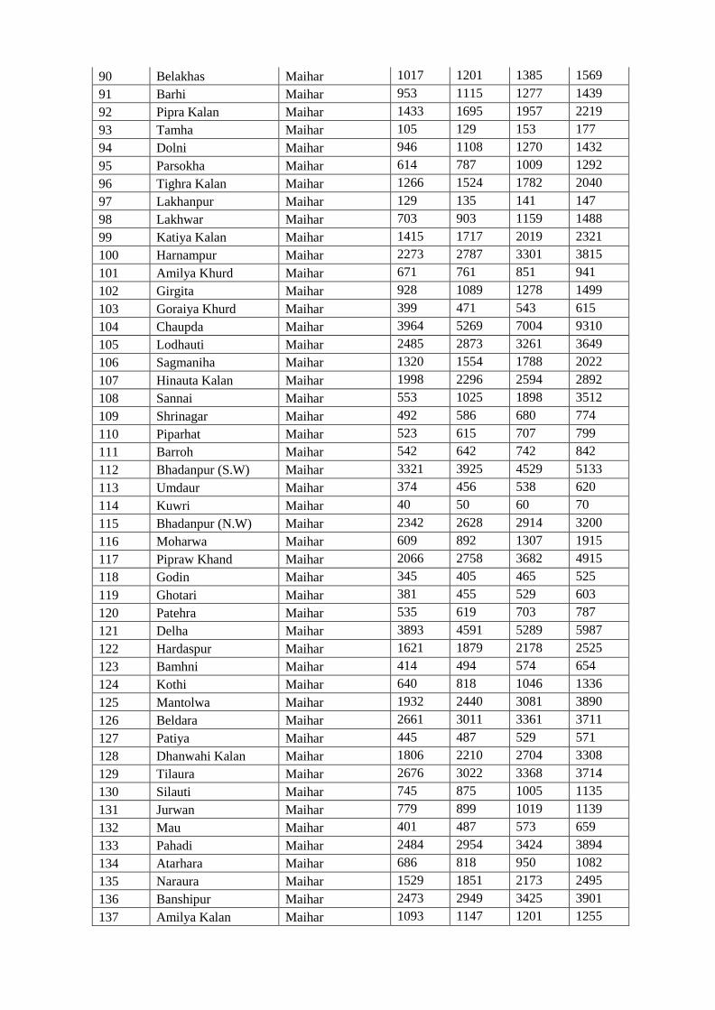
90 Belakhas Maihar 1017 1201 1385 1569
91 Barhi Maihar 953 1115 1277 1439
92 Pipra Kalan Maihar 1433 1695 1957 2219
93 Tamha Maihar 105 129 153 177
94 Dolni Maihar 946 1108 1270 1432
95 Parsokha Maihar 614 787 1009 1292
96 Tighra Kalan Maihar 1266 1524 1782 2040
97 Lakhanpur Maihar 129 135 141 147
98 Lakhwar Maihar 703 903 1159 1488
99 Katiya Kalan Maihar 1415 1717 2019 2321
100 Harnampur Maihar 2273 2787 3301 3815
101 Amilya Khurd Maihar 671 761 851 941
102 Girgita Maihar 928 1089 1278 1499
103 Goraiya Khurd Maihar 399 471 543 615
104 Chaupda Maihar 3964 5269 7004 9310
105 Lodhauti Maihar 2485 2873 3261 3649
106 Sagmaniha Maihar 1320 1554 1788 2022
107 Hinauta Kalan Maihar 1998 2296 2594 2892
108 Sannai Maihar 553 1025 1898 3512
109 Shrinagar Maihar 492 586 680 774
110 Piparhat Maihar 523 615 707 799
111 Barroh Maihar 542 642 742 842
112 Bhadanpur (S.W) Maihar 3321 3925 4529 5133
113 Umdaur Maihar 374 456 538 620
114 Kuwri Maihar 40 50 60 70
115 Bhadanpur (N.W) Maihar 2342 2628 2914 3200
116 Moharwa Maihar 609 892 1307 1915
117 Pipraw Khand Maihar 2066 2758 3682 4915
118 Godin Maihar 345 405 465 525
119 Ghotari Maihar 381 455 529 603
120 Patehra Maihar 535 619 703 787
121 Delha Maihar 3893 4591 5289 5987
122 Hardaspur Maihar 1621 1879 2178 2525
123 Bamhni Maihar 414 494 574 654
124 Kothi Maihar 640 818 1046 1336
125 Mantolwa Maihar 1932 2440 3081 3890
126 Beldara Maihar 2661 3011 3361 3711
127 Patiya Maihar 445 487 529 571
128 Dhanwahi Kalan Maihar 1806 2210 2704 3308
129 Tilaura Maihar 2676 3022 3368 3714
130 Silauti Maihar 745 875 1005 1135
131 Jurwan Maihar 779 899 1019 1139
132 Mau Maihar 401 487 573 659
133 Pahadi Maihar 2484 2954 3424 3894
134 Atarhara Maihar 686 818 950 1082
135 Naraura Maihar 1529 1851 2173 2495
136 Banshipur Maihar 2473 2949 3425 3901
137 Amilya Kalan Maihar 1093 1147 1201 1255
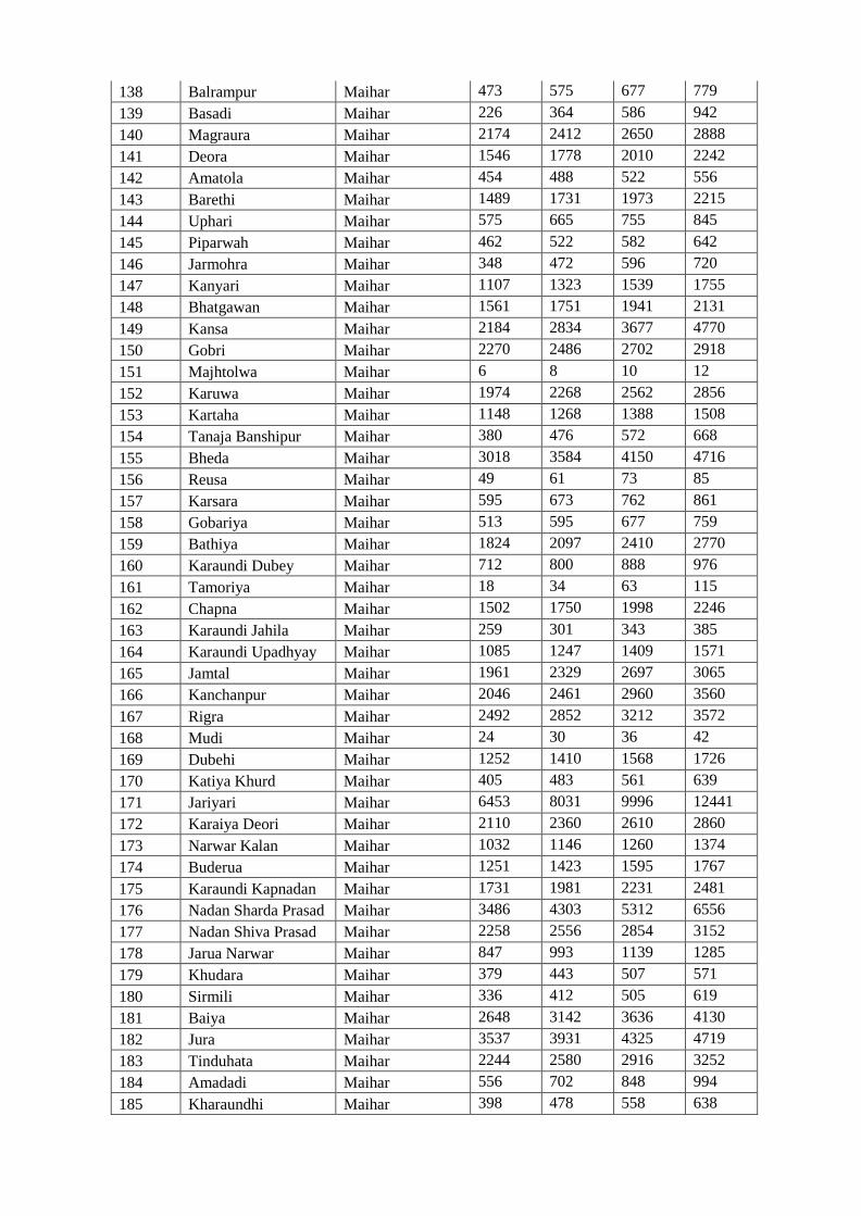
138 Balrampur Maihar 473 575 677 779
139 Basadi Maihar 226 364 586 942
140 Magraura Maihar 2174 2412 2650 2888
141 Deora Maihar 1546 1778 2010 2242
142 Amatola Maihar 454 488 522 556
143 Barethi Maihar 1489 1731 1973 2215
144 Uphari Maihar 575 665 755 845
145 Piparwah Maihar 462 522 582 642
146 Jarmohra Maihar 348 472 596 720
147 Kanyari Maihar 1107 1323 1539 1755
148 Bhatgawan Maihar 1561 1751 1941 2131
149 Kansa Maihar 2184 2834 3677 4770
150 Gobri Maihar 2270 2486 2702 2918
151 Majhtolwa Maihar 6 8 10 12
152 Karuwa Maihar 1974 2268 2562 2856
153 Kartaha Maihar 1148 1268 1388 1508
154 Tanaja Banshipur Maihar 380 476 572 668
155 Bheda Maihar 3018 3584 4150 4716
156 Reusa Maihar 49 61 73 85
157 Karsara Maihar 595 673 762 861
158 Gobariya Maihar 513 595 677 759
159 Bathiya Maihar 1824 2097 2410 2770
160 Karaundi Dubey Maihar 712 800 888 976
161 Tamoriya Maihar 18 34 63 115
162 Chapna Maihar 1502 1750 1998 2246
163 Karaundi Jahila Maihar 259 301 343 385
164 Karaundi Upadhyay Maihar 1085 1247 1409 1571
165 Jamtal Maihar 1961 2329 2697 3065
166 Kanchanpur Maihar 2046 2461 2960 3560
167 Rigra Maihar 2492 2852 3212 3572
168 Mudi Maihar 24 30 36 42
169 Dubehi Maihar 1252 1410 1568 1726
170 Katiya Khurd Maihar 405 483 561 639
171 Jariyari Maihar 6453 8031 9996 12441
172 Karaiya Deori Maihar 2110 2360 2610 2860
173 Narwar Kalan Maihar 1032 1146 1260 1374
174 Buderua Maihar 1251 1423 1595 1767
175 Karaundi Kapnadan Maihar 1731 1981 2231 2481
176 Nadan Sharda Prasad Maihar 3486 4303 5312 6556
177 Nadan Shiva Prasad Maihar 2258 2556 2854 3152
178 Jarua Narwar Maihar 847 993 1139 1285
179 Khudara Maihar 379 443 507 571
180 Sirmili Maihar 336 412 505 619
181 Baiya Maihar 2648 3142 3636 4130
182 Jura Maihar 3537 3931 4325 4719
183 Tinduhata Maihar 2244 2580 2916 3252
184 Amadadi Maihar 556 702 848 994
185 Kharaundhi Maihar 398 478 558 638
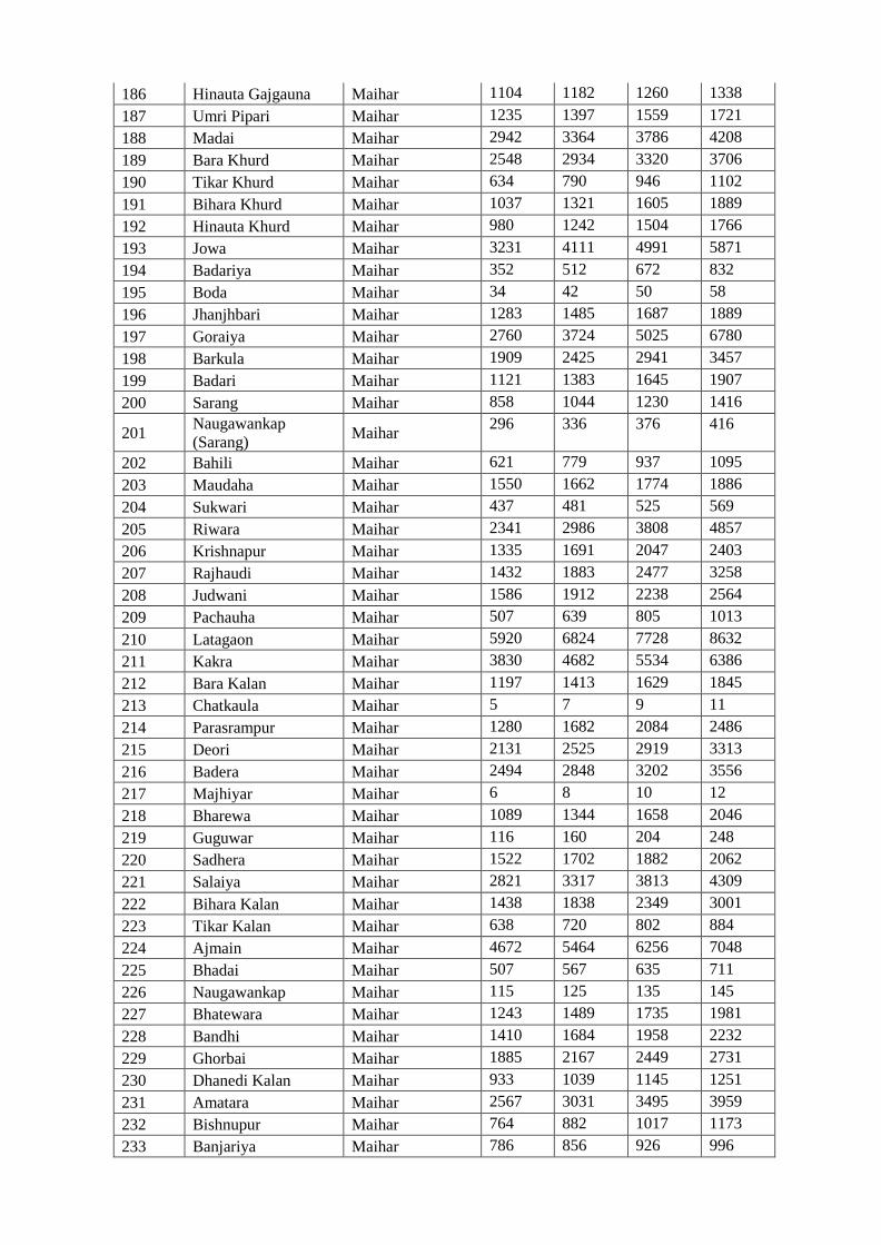
186 Hinauta Gajgauna Maihar 1104 1182 1260 1338
187 Umri Pipari Maihar 1235 1397 1559 1721
188 Madai Maihar 2942 3364 3786 4208
189 Bara Khurd Maihar 2548 2934 3320 3706
190 Tikar Khurd Maihar 634 790 946 1102
191 Bihara Khurd Maihar 1037 1321 1605 1889
192 Hinauta Khurd Maihar 980 1242 1504 1766
193 Jowa Maihar 3231 4111 4991 5871
194 Badariya Maihar 352 512 672 832
195 Boda Maihar 34 42 50 58
196 Jhanjhbari Maihar 1283 1485 1687 1889
197 Goraiya Maihar 2760 3724 5025 6780
198 Barkula Maihar 1909 2425 2941 3457
199 Badari Maihar 1121 1383 1645 1907
200 Sarang Maihar 858 1044 1230 1416
201 Naugawankap
(Sarang) Maihar
296 336 376 416
202 Bahili Maihar 621 779 937 1095
203 Maudaha Maihar 1550 1662 1774 1886
204 Sukwari Maihar 437 481 525 569
205 Riwara Maihar 2341 2986 3808 4857
206 Krishnapur Maihar 1335 1691 2047 2403
207 Rajhaudi Maihar 1432 1883 2477 3258
208 Judwani Maihar 1586 1912 2238 2564
209 Pachauha Maihar 507 639 805 1013
210 Latagaon Maihar 5920 6824 7728 8632
211 Kakra Maihar 3830 4682 5534 6386
212 Bara Kalan Maihar 1197 1413 1629 1845
213 Chatkaula Maihar 5 7 9 11
214 Parasrampur Maihar 1280 1682 2084 2486
215 Deori Maihar 2131 2525 2919 3313
216 Badera Maihar 2494 2848 3202 3556
217 Majhiyar Maihar 6 8 10 12
218 Bharewa Maihar 1089 1344 1658 2046
219 Guguwar Maihar 116 160 204 248
220 Sadhera Maihar 1522 1702 1882 2062
221 Salaiya Maihar 2821 3317 3813 4309
222 Bihara Kalan Maihar 1438 1838 2349 3001
223 Tikar Kalan Maihar 638 720 802 884
224 Ajmain Maihar 4672 5464 6256 7048
225 Bhadai Maihar 507 567 635 711
226 Naugawankap Maihar 115 125 135 145
227 Bhatewara Maihar 1243 1489 1735 1981
228 Bandhi Maihar 1410 1684 1958 2232
229 Ghorbai Maihar 1885 2167 2449 2731
230 Dhanedi Kalan Maihar 933 1039 1145 1251
231 Amatara Maihar 2567 3031 3495 3959
232 Bishnupur Maihar 764 882 1017 1173
233 Banjariya Maihar 786 856 926 996
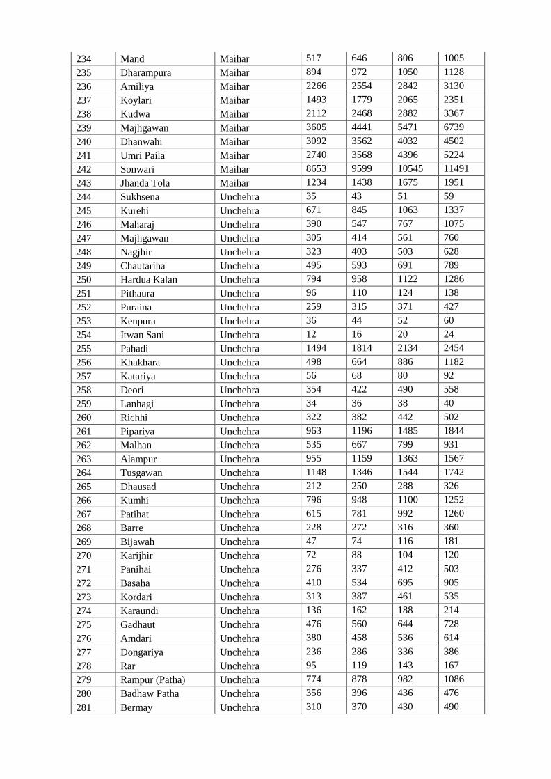
234 Mand Maihar 517 646 806 1005
235 Dharampura Maihar 894 972 1050 1128
236 Amiliya Maihar 2266 2554 2842 3130
237 Koylari Maihar 1493 1779 2065 2351
238 Kudwa Maihar 2112 2468 2882 3367
239 Majhgawan Maihar 3605 4441 5471 6739
240 Dhanwahi Maihar 3092 3562 4032 4502
241 Umri Paila Maihar 2740 3568 4396 5224
242 Sonwari Maihar 8653 9599 10545 11491
243 Jhanda Tola Maihar 1234 1438 1675 1951
244 Sukhsena Unchehra 35 43 51 59
245 Kurehi Unchehra 671 845 1063 1337
246 Maharaj Unchehra 390 547 767 1075
247 Majhgawan Unchehra 305 414 561 760
248 Nagjhir Unchehra 323 403 503 628
249 Chautariha Unchehra 495 593 691 789
250 Hardua Kalan Unchehra 794 958 1122 1286
251 Pithaura Unchehra 96 110 124 138
252 Puraina Unchehra 259 315 371 427
253 Kenpura Unchehra 36 44 52 60
254 Itwan Sani Unchehra 12 16 20 24
255 Pahadi Unchehra 1494 1814 2134 2454
256 Khakhara Unchehra 498 664 886 1182
257 Katariya Unchehra 56 68 80 92
258 Deori Unchehra 354 422 490 558
259 Lanhagi Unchehra 34 36 38 40
260 Richhi Unchehra 322 382 442 502
261 Pipariya Unchehra 963 1196 1485 1844
262 Malhan Unchehra 535 667 799 931
263 Alampur Unchehra 955 1159 1363 1567
264 Tusgawan Unchehra 1148 1346 1544 1742
265 Dhausad Unchehra 212 250 288 326
266 Kumhi Unchehra 796 948 1100 1252
267 Patihat Unchehra 615 781 992 1260
268 Barre Unchehra 228 272 316 360
269 Bijawah Unchehra 47 74 116 181
270 Karijhir Unchehra 72 88 104 120
271 Panihai Unchehra 276 337 412 503
272 Basaha Unchehra 410 534 695 905
273 Kordari Unchehra 313 387 461 535
274 Karaundi Unchehra 136 162 188 214
275 Gadhaut Unchehra 476 560 644 728
276 Amdari Unchehra 380 458 536 614
277 Dongariya Unchehra 236 286 336 386
278 Rar Unchehra 95 119 143 167
279 Rampur (Patha) Unchehra 774 878 982 1086
280 Badhaw Patha Unchehra 356 396 436 476
281 Bermay Unchehra 310 370 430 490
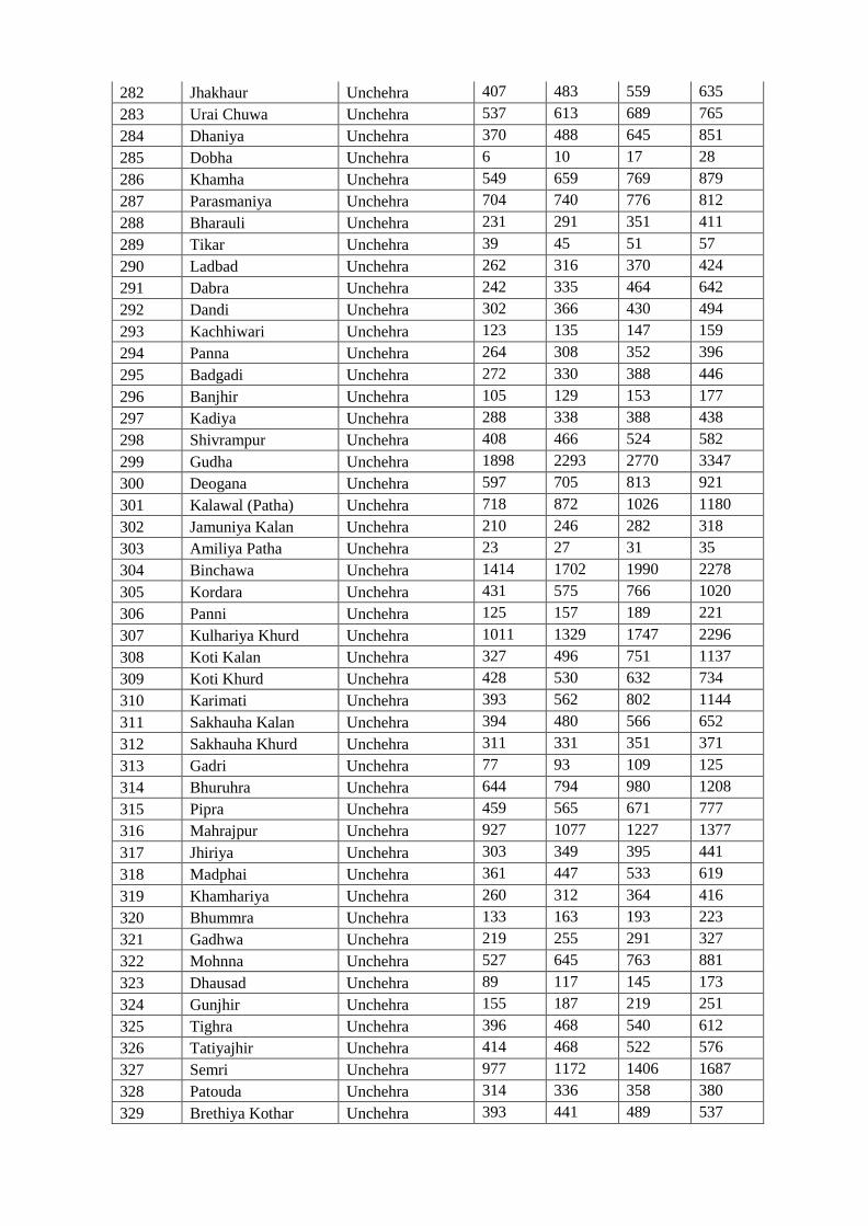
282 Jhakhaur Unchehra 407 483 559 635
283 Urai Chuwa Unchehra 537 613 689 765
284 Dhaniya Unchehra 370 488 645 851
285 Dobha Unchehra 6 10 17 28
286 Khamha Unchehra 549 659 769 879
287 Parasmaniya Unchehra 704 740 776 812
288 Bharauli Unchehra 231 291 351 411
289 Tikar Unchehra 39 45 51 57
290 Ladbad Unchehra 262 316 370 424
291 Dabra Unchehra 242 335 464 642
292 Dandi Unchehra 302 366 430 494
293 Kachhiwari Unchehra 123 135 147 159
294 Panna Unchehra 264 308 352 396
295 Badgadi Unchehra 272 330 388 446
296 Banjhir Unchehra 105 129 153 177
297 Kadiya Unchehra 288 338 388 438
298 Shivrampur Unchehra 408 466 524 582
299 Gudha Unchehra 1898 2293 2770 3347
300 Deogana Unchehra 597 705 813 921
301 Kalawal (Patha) Unchehra 718 872 1026 1180
302 Jamuniya Kalan Unchehra 210 246 282 318
303 Amiliya Patha Unchehra 23 27 31 35
304 Binchawa Unchehra 1414 1702 1990 2278
305 Kordara Unchehra 431 575 766 1020
306 Panni Unchehra 125 157 189 221
307 Kulhariya Khurd Unchehra 1011 1329 1747 2296
308 Koti Kalan Unchehra 327 496 751 1137
309 Koti Khurd Unchehra 428 530 632 734
310 Karimati Unchehra 393 562 802 1144
311 Sakhauha Kalan Unchehra 394 480 566 652
312 Sakhauha Khurd Unchehra 311 331 351 371
313 Gadri Unchehra 77 93 109 125
314 Bhuruhra Unchehra 644 794 980 1208
315 Pipra Unchehra 459 565 671 777
316 Mahrajpur Unchehra 927 1077 1227 1377
317 Jhiriya Unchehra 303 349 395 441
318 Madphai Unchehra 361 447 533 619
319 Khamhariya Unchehra 260 312 364 416
320 Bhummra Unchehra 133 163 193 223
321 Gadhwa Unchehra 219 255 291 327
322 Mohnna Unchehra 527 645 763 881
323 Dhausad Unchehra 89 117 145 173
324 Gunjhir Unchehra 155 187 219 251
325 Tighra Unchehra 396 468 540 612
326 Tatiyajhir Unchehra 414 468 522 576
327 Semri Unchehra 977 1172 1406 1687
328 Patouda Unchehra 314 336 358 380
329 Brethiya Kothar Unchehra 393 441 489 537
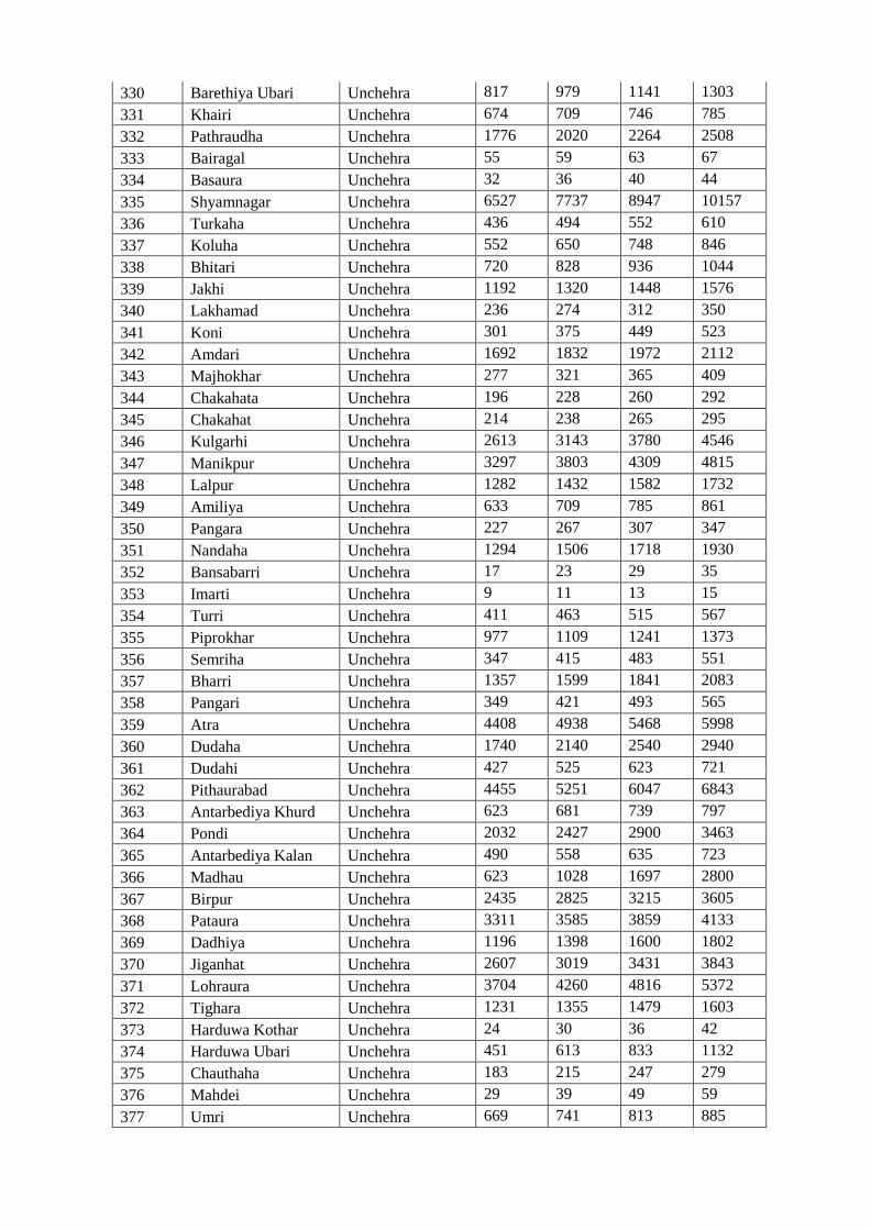
330 Barethiya Ubari Unchehra 817 979 1141 1303
331 Khairi Unchehra 674 709 746 785
332 Pathraudha Unchehra 1776 2020 2264 2508
333 Bairagal Unchehra 55 59 63 67
334 Basaura Unchehra 32 36 40 44
335 Shyamnagar Unchehra 6527 7737 8947 10157
336 Turkaha Unchehra 436 494 552 610
337 Koluha Unchehra 552 650 748 846
338 Bhitari Unchehra 720 828 936 1044
339 Jakhi Unchehra 1192 1320 1448 1576
340 Lakhamad Unchehra 236 274 312 350
341 Koni Unchehra 301 375 449 523
342 Amdari Unchehra 1692 1832 1972 2112
343 Majhokhar Unchehra 277 321 365 409
344 Chakahata Unchehra 196 228 260 292
345 Chakahat Unchehra 214 238 265 295
346 Kulgarhi Unchehra 2613 3143 3780 4546
347 Manikpur Unchehra 3297 3803 4309 4815
348 Lalpur Unchehra 1282 1432 1582 1732
349 Amiliya Unchehra 633 709 785 861
350 Pangara Unchehra 227 267 307 347
351 Nandaha Unchehra 1294 1506 1718 1930
352 Bansabarri Unchehra 17 23 29 35
353 Imarti Unchehra 9 11 13 15
354 Turri Unchehra 411 463 515 567
355 Piprokhar Unchehra 977 1109 1241 1373
356 Semriha Unchehra 347 415 483 551
357 Bharri Unchehra 1357 1599 1841 2083
358 Pangari Unchehra 349 421 493 565
359 Atra Unchehra 4408 4938 5468 5998
360 Dudaha Unchehra 1740 2140 2540 2940
361 Dudahi Unchehra 427 525 623 721
362 Pithaurabad Unchehra 4455 5251 6047 6843
363 Antarbediya Khurd Unchehra 623 681 739 797
364 Pondi Unchehra 2032 2427 2900 3463
365 Antarbediya Kalan Unchehra 490 558 635 723
366 Madhau Unchehra 623 1028 1697 2800
367 Birpur Unchehra 2435 2825 3215 3605
368 Pataura Unchehra 3311 3585 3859 4133
369 Dadhiya Unchehra 1196 1398 1600 1802
370 Jiganhat Unchehra 2607 3019 3431 3843
371 Lohraura Unchehra 3704 4260 4816 5372
372 Tighara Unchehra 1231 1355 1479 1603
373 Harduwa Kothar Unchehra 24 30 36 42
374 Harduwa Ubari Unchehra 451 613 833 1132
375 Chauthaha Unchehra 183 215 247 279
376 Mahdei Unchehra 29 39 49 59
377 Umri Unchehra 669 741 813 885
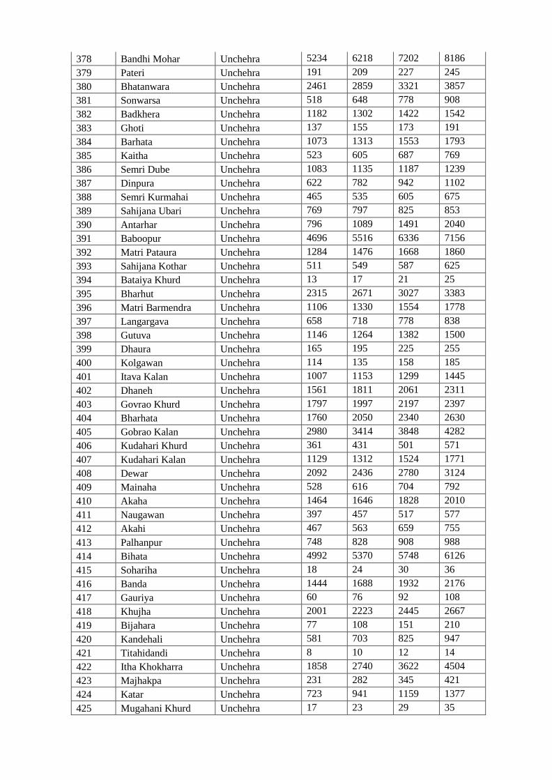
378 Bandhi Mohar Unchehra 5234 6218 7202 8186
379 Pateri Unchehra 191 209 227 245
380 Bhatanwara Unchehra 2461 2859 3321 3857
381 Sonwarsa Unchehra 518 648 778 908
382 Badkhera Unchehra 1182 1302 1422 1542
383 Ghoti Unchehra 137 155 173 191
384 Barhata Unchehra 1073 1313 1553 1793
385 Kaitha Unchehra 523 605 687 769
386 Semri Dube Unchehra 1083 1135 1187 1239
387 Dinpura Unchehra 622 782 942 1102
388 Semri Kurmahai Unchehra 465 535 605 675
389 Sahijana Ubari Unchehra 769 797 825 853
390 Antarhar Unchehra 796 1089 1491 2040
391 Baboopur Unchehra 4696 5516 6336 7156
392 Matri Pataura Unchehra 1284 1476 1668 1860
393 Sahijana Kothar Unchehra 511 549 587 625
394 Bataiya Khurd Unchehra 13 17 21 25
395 Bharhut Unchehra 2315 2671 3027 3383
396 Matri Barmendra Unchehra 1106 1330 1554 1778
397 Langargava Unchehra 658 718 778 838
398 Gutuva Unchehra 1146 1264 1382 1500
399 Dhaura Unchehra 165 195 225 255
400 Kolgawan Unchehra 114 135 158 185
401 Itava Kalan Unchehra 1007 1153 1299 1445
402 Dhaneh Unchehra 1561 1811 2061 2311
403 Govrao Khurd Unchehra 1797 1997 2197 2397
404 Bharhata Unchehra 1760 2050 2340 2630
405 Gobrao Kalan Unchehra 2980 3414 3848 4282
406 Kudahari Khurd Unchehra 361 431 501 571
407 Kudahari Kalan Unchehra 1129 1312 1524 1771
408 Dewar Unchehra 2092 2436 2780 3124
409 Mainaha Unchehra 528 616 704 792
410 Akaha Unchehra 1464 1646 1828 2010
411 Naugawan Unchehra 397 457 517 577
412 Akahi Unchehra 467 563 659 755
413 Palhanpur Unchehra 748 828 908 988
414 Bihata Unchehra 4992 5370 5748 6126
415 Sohariha Unchehra 18 24 30 36
416 Banda Unchehra 1444 1688 1932 2176
417 Gauriya Unchehra 60 76 92 108
418 Khujha Unchehra 2001 2223 2445 2667
419 Bijahara Unchehra 77 108 151 210
420 Kandehali Unchehra 581 703 825 947
421 Titahidandi Unchehra 8 10 12 14
422 Itha Khokharra Unchehra 1858 2740 3622 4504
423 Majhakpa Unchehra 231 282 345 421
424 Katar Unchehra 723 941 1159 1377
425 Mugahani Khurd Unchehra 17 23 29 35
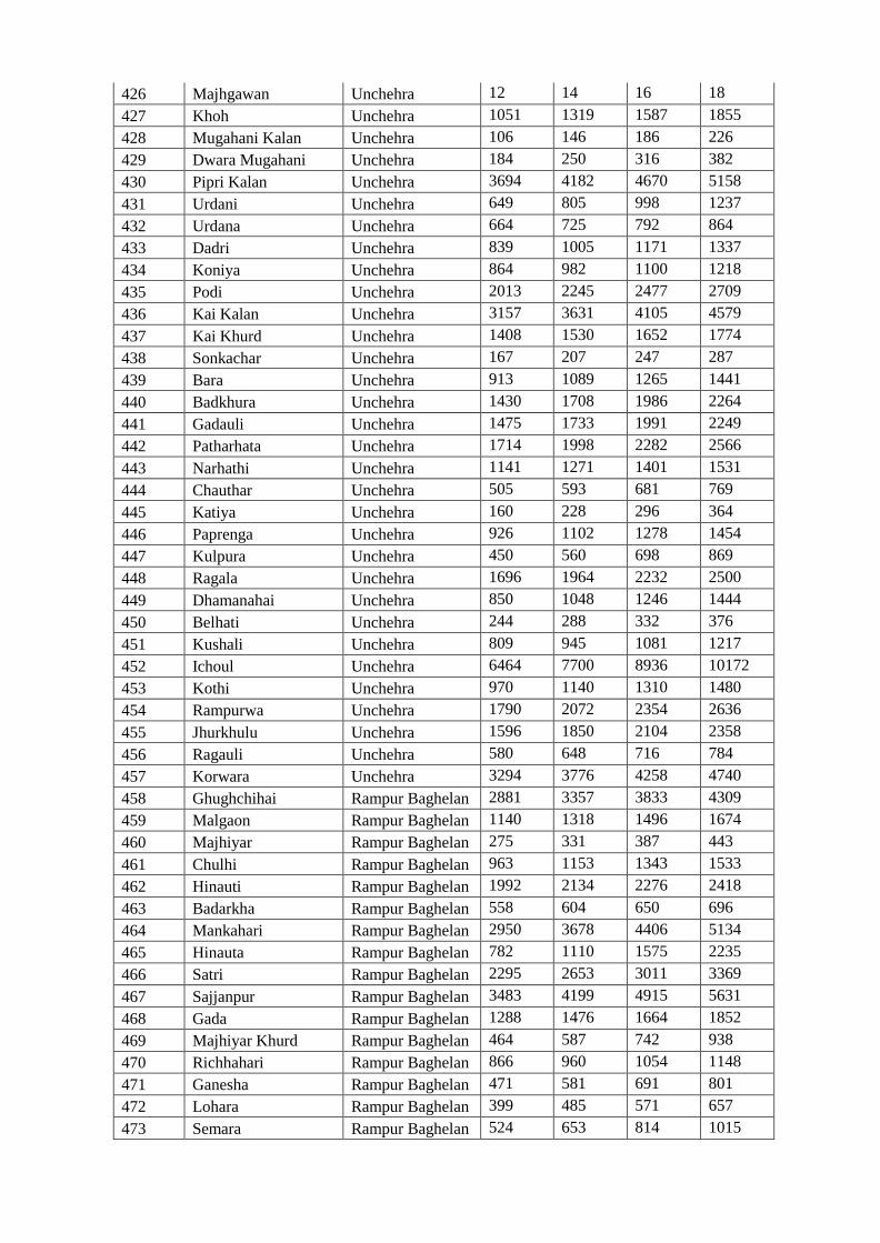
426 Majhgawan Unchehra 12 14 16 18
427 Khoh Unchehra 1051 1319 1587 1855
428 Mugahani Kalan Unchehra 106 146 186 226
429 Dwara Mugahani Unchehra 184 250 316 382
430 Pipri Kalan Unchehra 3694 4182 4670 5158
431 Urdani Unchehra 649 805 998 1237
432 Urdana Unchehra 664 725 792 864
433 Dadri Unchehra 839 1005 1171 1337
434 Koniya Unchehra 864 982 1100 1218
435 Podi Unchehra 2013 2245 2477 2709
436 Kai Kalan Unchehra 3157 3631 4105 4579
437 Kai Khurd Unchehra 1408 1530 1652 1774
438 Sonkachar Unchehra 167 207 247 287
439 Bara Unchehra 913 1089 1265 1441
440 Badkhura Unchehra 1430 1708 1986 2264
441 Gadauli Unchehra 1475 1733 1991 2249
442 Patharhata Unchehra 1714 1998 2282 2566
443 Narhathi Unchehra 1141 1271 1401 1531
444 Chauthar Unchehra 505 593 681 769
445 Katiya Unchehra 160 228 296 364
446 Paprenga Unchehra 926 1102 1278 1454
447 Kulpura Unchehra 450 560 698 869
448 Ragala Unchehra 1696 1964 2232 2500
449 Dhamanahai Unchehra 850 1048 1246 1444
450 Belhati Unchehra 244 288 332 376
451 Kushali Unchehra 809 945 1081 1217
452 Ichoul Unchehra 6464 7700 8936 10172
453 Kothi Unchehra 970 1140 1310 1480
454 Rampurwa Unchehra 1790 2072 2354 2636
455 Jhurkhulu Unchehra 1596 1850 2104 2358
456 Ragauli Unchehra 580 648 716 784
457 Korwara Unchehra 3294 3776 4258 4740
458 Ghughchihai Rampur Baghelan 2881 3357 3833 4309
459 Malgaon Rampur Baghelan 1140 1318 1496 1674
460 Majhiyar Rampur Baghelan 275 331 387 443
461 Chulhi Rampur Baghelan 963 1153 1343 1533
462 Hinauti Rampur Baghelan 1992 2134 2276 2418
463 Badarkha Rampur Baghelan 558 604 650 696
464 Mankahari Rampur Baghelan 2950 3678 4406 5134
465 Hinauta Rampur Baghelan 782 1110 1575 2235
466 Satri Rampur Baghelan 2295 2653 3011 3369
467 Sajjanpur Rampur Baghelan 3483 4199 4915 5631
468 Gada Rampur Baghelan 1288 1476 1664 1852
469 Majhiyar Khurd Rampur Baghelan 464 587 742 938
470 Richhahari Rampur Baghelan 866 960 1054 1148
471 Ganesha Rampur Baghelan 471 581 691 801
472 Lohara Rampur Baghelan 399 485 571 657
473 Semara Rampur Baghelan 524 653 814 1015
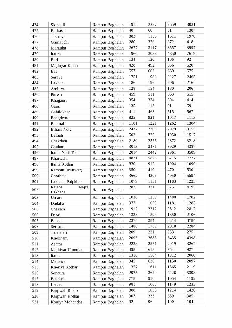
474 Sidhauli Rampur Baghelan 1915 2287 2659 3031
475 Barbasa Rampur Baghelan 40 60 91 138
476 Tikuriya Rampur Baghelan 883 1155 1511 1976
477 Ghinauchi Rampur Baghelan 280 326 372 418
478 Marauha Rampur Baghelan 2677 3117 3557 3997
479 Itaura Rampur Baghelan 1966 3088 4850 7619
480 Bari Rampur Baghelan 134 120 106 92
481 Majhiyar Kalan Rampur Baghelan 428 492 556 620
482 Baa Rampur Baghelan 657 663 669 675
483 Saraya Rampur Baghelan 1751 1989 2227 2465
484 Lakhaha Rampur Baghelan 186 196 206 216
485 Amiliya Rampur Baghelan 128 154 180 206
486 Purwa Rampur Baghelan 459 511 563 615
487 Khagaura Rampur Baghelan 354 374 394 414
488 Gauri Rampur Baghelan 135 113 91 69
489 Gahilokhar Rampur Baghelan 411 463 515 567
490 Bhagdeora Rampur Baghelan 825 921 1017 1113
491 Beernai Rampur Baghelan 1181 1221 1262 1304
492 Bihara No.2 Rampur Baghelan 2477 2703 2929 3155
493 Belhati Rampur Baghelan 502 726 1050 1517
494 Chakdahi Rampur Baghelan 2180 2526 2872 3218
495 Gauhari Rampur Baghelan 3013 3471 3929 4387
496 Itama Nadi Teer Rampur Baghelan 2014 2442 2961 3589
497 Kharwahi Rampur Baghelan 4871 5823 6775 7727
498 Itama Kothar Rampur Baghelan 820 912 1004 1096
499 Rampur (Murwar) Rampur Baghelan 350 410 470 530
500 Chorhata Rampur Baghelan 3662 4306 4950 5594
501 Lakhaha Paipkhar Rampur Baghelan 1079 1131 1183 1235
502 Rajaha Majra
Lakhaha Rampur Baghelan
287 331 375 419
503 Umari Rampur Baghelan 1036 1258 1480 1702
504 Dudaha Rampur Baghelan 977 1079 1181 1283
505 Chakera Rampur Baghelan 1912 2212 2512 2812
506 Deori Rampur Baghelan 1338 1594 1850 2106
507 Beeda Rampur Baghelan 2374 2844 3314 3784
508 Semara Rampur Baghelan 1486 1752 2018 2284
509 Talatalari Rampur Baghelan 209 231 253 275
510 Khokham Rampur Baghelan 2095 2683 3435 4398
511 Asarar Rampur Baghelan 2223 2571 2919 3267
512 Majhiyar Unmulan Rampur Baghelan 498 613 754 927
513 Itama Rampur Baghelan 1316 1564 1812 2060
514 Mahewa Rampur Baghelan 345 630 1150 2097
515 Kheriya Kothar Rampur Baghelan 1357 1611 1865 2119
516 Sonaura Rampur Baghelan 2975 3629 4426 5398
517 Bhadari Rampur Baghelan 778 916 1054 1192
518 Ledara Rampur Baghelan 981 1065 1149 1233
519 Karpwah Bhaip Rampur Baghelan 888 1038 1214 1420
520 Karpwah Kothar Rampur Baghelan 307 333 359 385
521 Koniya Mohandas Rampur Baghelan 92 96 100 104
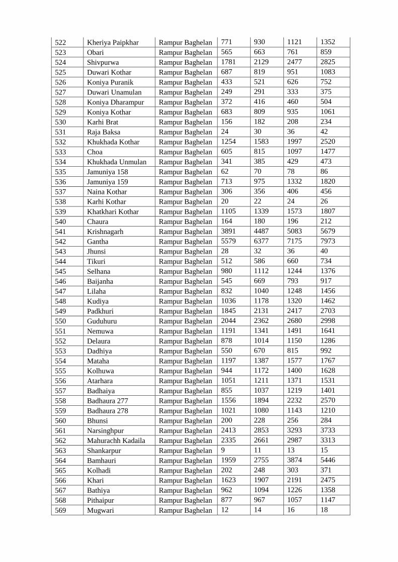
522 Kheriya Paipkhar Rampur Baghelan 771 930 1121 1352
523 Obari Rampur Baghelan 565 663 761 859
524 Shivpurwa Rampur Baghelan 1781 2129 2477 2825
525 Duwari Kothar Rampur Baghelan 687 819 951 1083
526 Koniya Puranik Rampur Baghelan 433 521 626 752
527 Duwari Unamulan Rampur Baghelan 249 291 333 375
528 Koniya Dharampur Rampur Baghelan 372 416 460 504
529 Koniya Kothar Rampur Baghelan 683 809 935 1061
530 Karhi Brat Rampur Baghelan 156 182 208 234
531 Raja Baksa Rampur Baghelan 24 30 36 42
532 Khukhada Kothar Rampur Baghelan 1254 1583 1997 2520
533 Choa Rampur Baghelan 605 815 1097 1477
534 Khukhada Unmulan Rampur Baghelan 341 385 429 473
535 Jamuniya 158 Rampur Baghelan 62 70 78 86
536 Jamuniya 159 Rampur Baghelan 713 975 1332 1820
537 Naina Kothar Rampur Baghelan 306 356 406 456
538 Karhi Kothar Rampur Baghelan 20 22 24 26
539 Khatkhari Kothar Rampur Baghelan 1105 1339 1573 1807
540 Chaura Rampur Baghelan 164 180 196 212
541 Krishnagarh Rampur Baghelan 3891 4487 5083 5679
542 Gantha Rampur Baghelan 5579 6377 7175 7973
543 Jhunsi Rampur Baghelan 28 32 36 40
544 Tikuri Rampur Baghelan 512 586 660 734
545 Selhana Rampur Baghelan 980 1112 1244 1376
546 Baijanha Rampur Baghelan 545 669 793 917
547 Lilaha Rampur Baghelan 832 1040 1248 1456
548 Kudiya Rampur Baghelan 1036 1178 1320 1462
549 Padkhuri Rampur Baghelan 1845 2131 2417 2703
550 Guduhuru Rampur Baghelan 2044 2362 2680 2998
551 Nemuwa Rampur Baghelan 1191 1341 1491 1641
552 Delaura Rampur Baghelan 878 1014 1150 1286
553 Dadhiya Rampur Baghelan 550 670 815 992
554 Mataha Rampur Baghelan 1197 1387 1577 1767
555 Kolhuwa Rampur Baghelan 944 1172 1400 1628
556 Atarhara Rampur Baghelan 1051 1211 1371 1531
557 Badhaiya Rampur Baghelan 855 1037 1219 1401
558 Badhaura 277 Rampur Baghelan 1556 1894 2232 2570
559 Badhaura 278 Rampur Baghelan 1021 1080 1143 1210
560 Bhunsi Rampur Baghelan 200 228 256 284
561 Narsinghpur Rampur Baghelan 2413 2853 3293 3733
562 Mahurachh Kadaila Rampur Baghelan 2335 2661 2987 3313
563 Shankarpur Rampur Baghelan 9 11 13 15
564 Bamhauri Rampur Baghelan 1959 2755 3874 5446
565 Kolhadi Rampur Baghelan 202 248 303 371
566 Khari Rampur Baghelan 1623 1907 2191 2475
567 Bathiya Rampur Baghelan 962 1094 1226 1358
568 Pithaipur Rampur Baghelan 877 967 1057 1147
569 Mugwari Rampur Baghelan 12 14 16 18
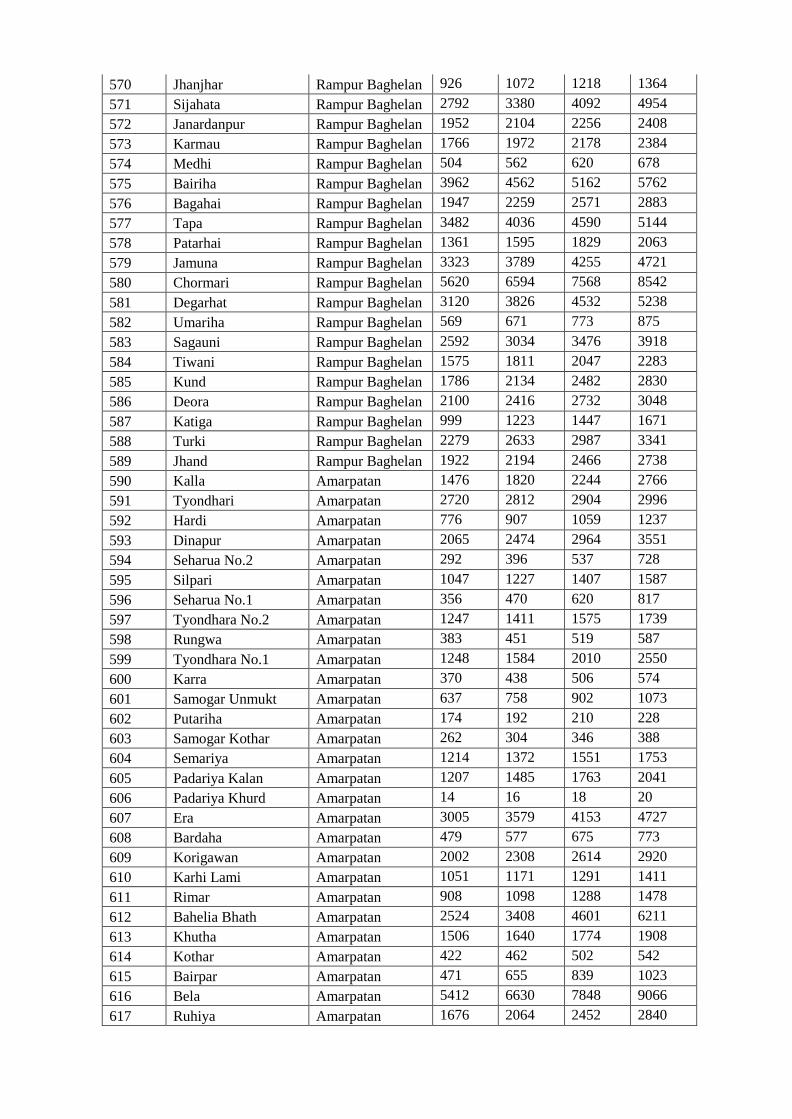
570 Jhanjhar Rampur Baghelan 926 1072 1218 1364
571 Sijahata Rampur Baghelan 2792 3380 4092 4954
572 Janardanpur Rampur Baghelan 1952 2104 2256 2408
573 Karmau Rampur Baghelan 1766 1972 2178 2384
574 Medhi Rampur Baghelan 504 562 620 678
575 Bairiha Rampur Baghelan 3962 4562 5162 5762
576 Bagahai Rampur Baghelan 1947 2259 2571 2883
577 Tapa Rampur Baghelan 3482 4036 4590 5144
578 Patarhai Rampur Baghelan 1361 1595 1829 2063
579 Jamuna Rampur Baghelan 3323 3789 4255 4721
580 Chormari Rampur Baghelan 5620 6594 7568 8542
581 Degarhat Rampur Baghelan 3120 3826 4532 5238
582 Umariha Rampur Baghelan 569 671 773 875
583 Sagauni Rampur Baghelan 2592 3034 3476 3918
584 Tiwani Rampur Baghelan 1575 1811 2047 2283
585 Kund Rampur Baghelan 1786 2134 2482 2830
586 Deora Rampur Baghelan 2100 2416 2732 3048
587 Katiga Rampur Baghelan 999 1223 1447 1671
588 Turki Rampur Baghelan 2279 2633 2987 3341
589 Jhand Rampur Baghelan 1922 2194 2466 2738
590 Kalla Amarpatan 1476 1820 2244 2766
591 Tyondhari Amarpatan 2720 2812 2904 2996
592 Hardi Amarpatan 776 907 1059 1237
593 Dinapur Amarpatan 2065 2474 2964 3551
594 Seharua No.2 Amarpatan 292 396 537 728
595 Silpari Amarpatan 1047 1227 1407 1587
596 Seharua No.1 Amarpatan 356 470 620 817
597 Tyondhara No.2 Amarpatan 1247 1411 1575 1739
598 Rungwa Amarpatan 383 451 519 587
599 Tyondhara No.1 Amarpatan 1248 1584 2010 2550
600 Karra Amarpatan 370 438 506 574
601 Samogar Unmukt Amarpatan 637 758 902 1073
602 Putariha Amarpatan 174 192 210 228
603 Samogar Kothar Amarpatan 262 304 346 388
604 Semariya Amarpatan 1214 1372 1551 1753
605 Padariya Kalan Amarpatan 1207 1485 1763 2041
606 Padariya Khurd Amarpatan 14 16 18 20
607 Era Amarpatan 3005 3579 4153 4727
608 Bardaha Amarpatan 479 577 675 773
609 Korigawan Amarpatan 2002 2308 2614 2920
610 Karhi Lami Amarpatan 1051 1171 1291 1411
611 Rimar Amarpatan 908 1098 1288 1478
612 Bahelia Bhath Amarpatan 2524 3408 4601 6211
613 Khutha Amarpatan 1506 1640 1774 1908
614 Kothar Amarpatan 422 462 502 542
615 Bairpar Amarpatan 471 655 839 1023
616 Bela Amarpatan 5412 6630 7848 9066
617 Ruhiya Amarpatan 1676 2064 2452 2840
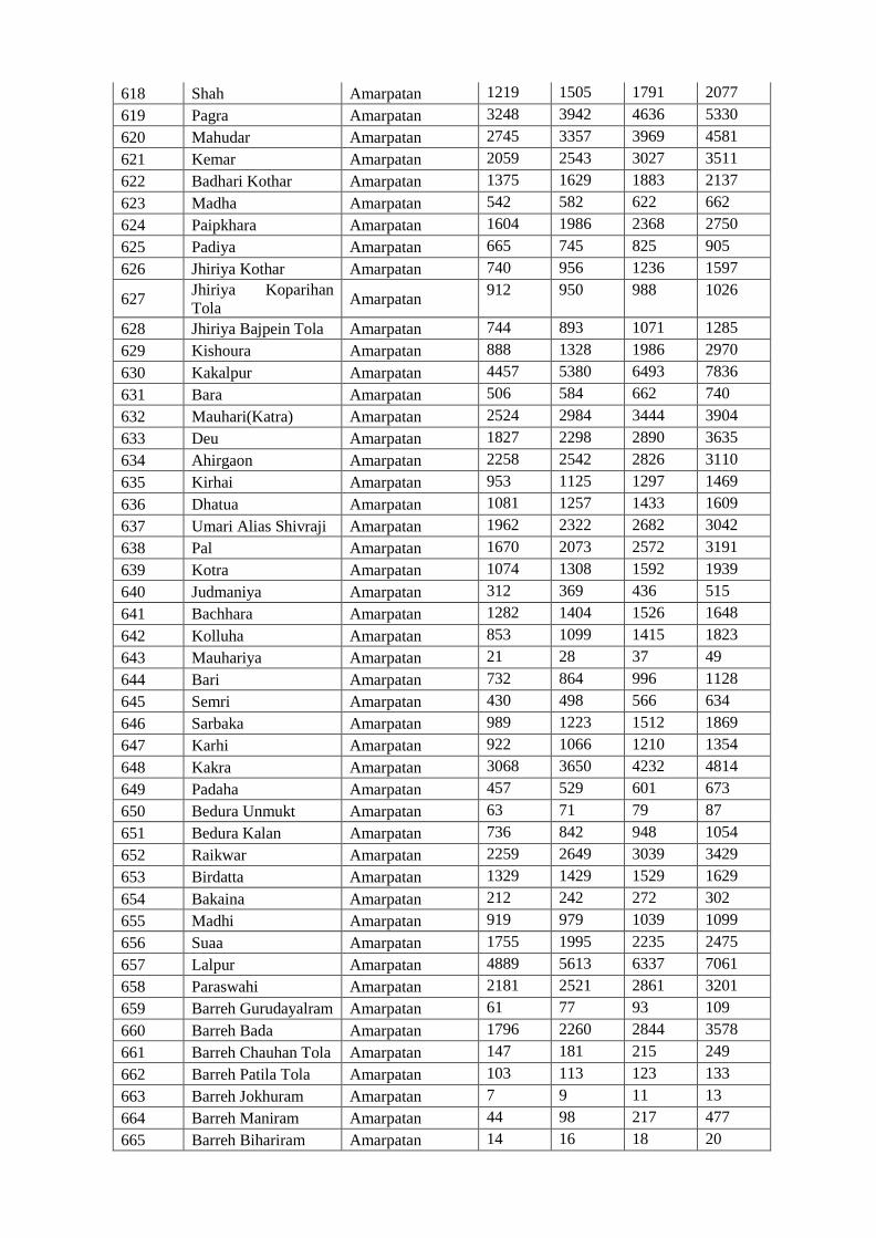
618 Shah Amarpatan 1219 1505 1791 2077
619 Pagra Amarpatan 3248 3942 4636 5330
620 Mahudar Amarpatan 2745 3357 3969 4581
621 Kemar Amarpatan 2059 2543 3027 3511
622 Badhari Kothar Amarpatan 1375 1629 1883 2137
623 Madha Amarpatan 542 582 622 662
624 Paipkhara Amarpatan 1604 1986 2368 2750
625 Padiya Amarpatan 665 745 825 905
626 Jhiriya Kothar Amarpatan 740 956 1236 1597
627 Jhiriya Koparihan
Tola Amarpatan
912 950 988 1026
628 Jhiriya Bajpein Tola Amarpatan 744 893 1071 1285
629 Kishoura Amarpatan 888 1328 1986 2970
630 Kakalpur Amarpatan 4457 5380 6493 7836
631 Bara Amarpatan 506 584 662 740
632 Mauhari(Katra) Amarpatan 2524 2984 3444 3904
633 Deu Amarpatan 1827 2298 2890 3635
634 Ahirgaon Amarpatan 2258 2542 2826 3110
635 Kirhai Amarpatan 953 1125 1297 1469
636 Dhatua Amarpatan 1081 1257 1433 1609
637 Umari Alias Shivraji Amarpatan 1962 2322 2682 3042
638 Pal Amarpatan 1670 2073 2572 3191
639 Kotra Amarpatan 1074 1308 1592 1939
640 Judmaniya Amarpatan 312 369 436 515
641 Bachhara Amarpatan 1282 1404 1526 1648
642 Kolluha Amarpatan 853 1099 1415 1823
643 Mauhariya Amarpatan 21 28 37 49
644 Bari Amarpatan 732 864 996 1128
645 Semri Amarpatan 430 498 566 634
646 Sarbaka Amarpatan 989 1223 1512 1869
647 Karhi Amarpatan 922 1066 1210 1354
648 Kakra Amarpatan 3068 3650 4232 4814
649 Padaha Amarpatan 457 529 601 673
650 Bedura Unmukt Amarpatan 63 71 79 87
651 Bedura Kalan Amarpatan 736 842 948 1054
652 Raikwar Amarpatan 2259 2649 3039 3429
653 Birdatta Amarpatan 1329 1429 1529 1629
654 Bakaina Amarpatan 212 242 272 302
655 Madhi Amarpatan 919 979 1039 1099
656 Suaa Amarpatan 1755 1995 2235 2475
657 Lalpur Amarpatan 4889 5613 6337 7061
658 Paraswahi Amarpatan 2181 2521 2861 3201
659 Barreh Gurudayalram Amarpatan 61 77 93 109
660 Barreh Bada Amarpatan 1796 2260 2844 3578
661 Barreh Chauhan Tola Amarpatan 147 181 215 249
662 Barreh Patila Tola Amarpatan 103 113 123 133
663 Barreh Jokhuram Amarpatan 7 9 11 13
664 Barreh Maniram Amarpatan 44 98 217 477
665 Barreh Bihariram Amarpatan 14 16 18 20
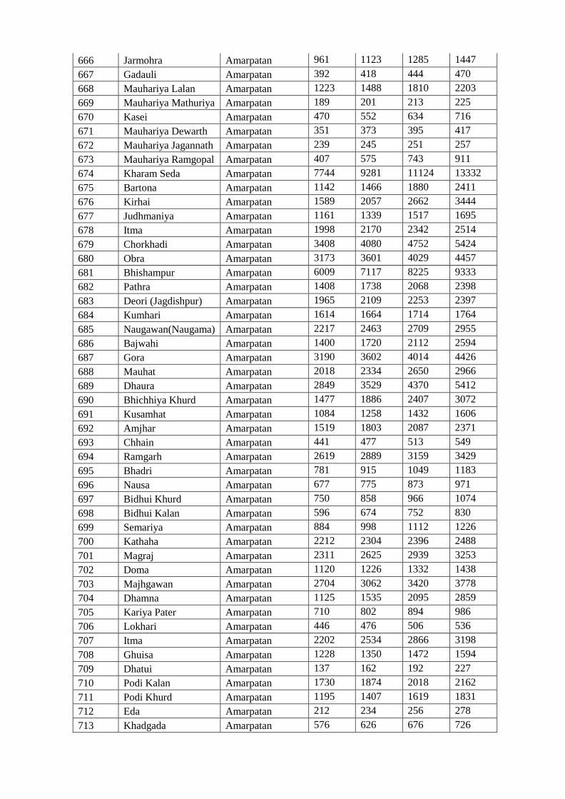
666 Jarmohra Amarpatan 961 1123 1285 1447
667 Gadauli Amarpatan 392 418 444 470
668 Mauhariya Lalan Amarpatan 1223 1488 1810 2203
669 Mauhariya Mathuriya Amarpatan 189 201 213 225
670 Kasei Amarpatan 470 552 634 716
671 Mauhariya Dewarth Amarpatan 351 373 395 417
672 Mauhariya Jagannath Amarpatan 239 245 251 257
673 Mauhariya Ramgopal Amarpatan 407 575 743 911
674 Kharam Seda Amarpatan 7744 9281 11124 13332
675 Bartona Amarpatan 1142 1466 1880 2411
676 Kirhai Amarpatan 1589 2057 2662 3444
677 Judhmaniya Amarpatan 1161 1339 1517 1695
678 Itma Amarpatan 1998 2170 2342 2514
679 Chorkhadi Amarpatan 3408 4080 4752 5424
680 Obra Amarpatan 3173 3601 4029 4457
681 Bhishampur Amarpatan 6009 7117 8225 9333
682 Pathra Amarpatan 1408 1738 2068 2398
683 Deori (Jagdishpur) Amarpatan 1965 2109 2253 2397
684 Kumhari Amarpatan 1614 1664 1714 1764
685 Naugawan(Naugama) Amarpatan 2217 2463 2709 2955
686 Bajwahi Amarpatan 1400 1720 2112 2594
687 Gora Amarpatan 3190 3602 4014 4426
688 Mauhat Amarpatan 2018 2334 2650 2966
689 Dhaura Amarpatan 2849 3529 4370 5412
690 Bhichhiya Khurd Amarpatan 1477 1886 2407 3072
691 Kusamhat Amarpatan 1084 1258 1432 1606
692 Amjhar Amarpatan 1519 1803 2087 2371
693 Chhain Amarpatan 441 477 513 549
694 Ramgarh Amarpatan 2619 2889 3159 3429
695 Bhadri Amarpatan 781 915 1049 1183
696 Nausa Amarpatan 677 775 873 971
697 Bidhui Khurd Amarpatan 750 858 966 1074
698 Bidhui Kalan Amarpatan 596 674 752 830
699 Semariya Amarpatan 884 998 1112 1226
700 Kathaha Amarpatan 2212 2304 2396 2488
701 Magraj Amarpatan 2311 2625 2939 3253
702 Doma Amarpatan 1120 1226 1332 1438
703 Majhgawan Amarpatan 2704 3062 3420 3778
704 Dhamna Amarpatan 1125 1535 2095 2859
705 Kariya Pater Amarpatan 710 802 894 986
706 Lokhari Amarpatan 446 476 506 536
707 Itma Amarpatan 2202 2534 2866 3198
708 Ghuisa Amarpatan 1228 1350 1472 1594
709 Dhatui Amarpatan 137 162 192 227
710 Podi Kalan Amarpatan 1730 1874 2018 2162
711 Podi Khurd Amarpatan 1195 1407 1619 1831
712 Eda Amarpatan 212 234 256 278
713 Khadgada Amarpatan 576 626 676 726
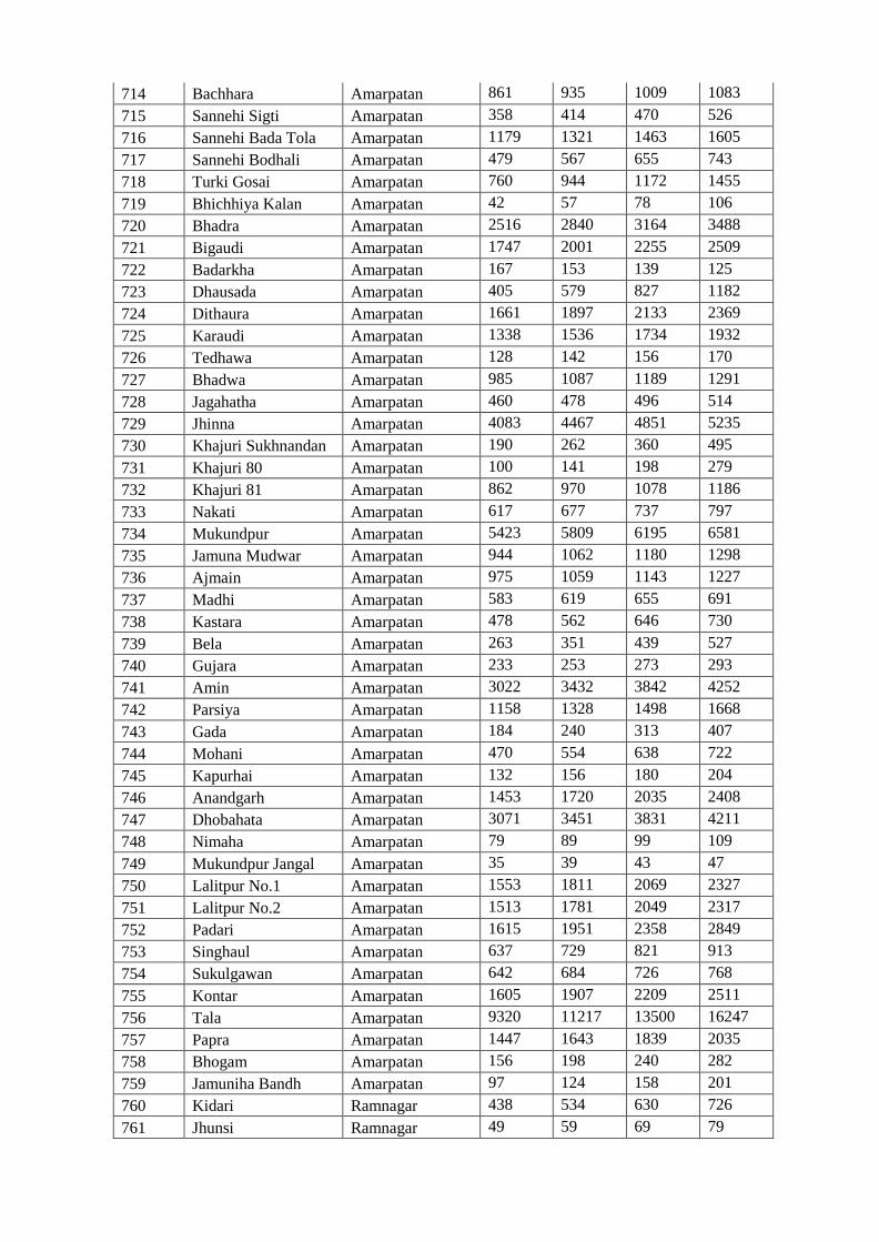
714 Bachhara Amarpatan 861 935 1009 1083
715 Sannehi Sigti Amarpatan 358 414 470 526
716 Sannehi Bada Tola Amarpatan 1179 1321 1463 1605
717 Sannehi Bodhali Amarpatan 479 567 655 743
718 Turki Gosai Amarpatan 760 944 1172 1455
719 Bhichhiya Kalan Amarpatan 42 57 78 106
720 Bhadra Amarpatan 2516 2840 3164 3488
721 Bigaudi Amarpatan 1747 2001 2255 2509
722 Badarkha Amarpatan 167 153 139 125
723 Dhausada Amarpatan 405 579 827 1182
724 Dithaura Amarpatan 1661 1897 2133 2369
725 Karaudi Amarpatan 1338 1536 1734 1932
726 Tedhawa Amarpatan 128 142 156 170
727 Bhadwa Amarpatan 985 1087 1189 1291
728 Jagahatha Amarpatan 460 478 496 514
729 Jhinna Amarpatan 4083 4467 4851 5235
730 Khajuri Sukhnandan Amarpatan 190 262 360 495
731 Khajuri 80 Amarpatan 100 141 198 279
732 Khajuri 81 Amarpatan 862 970 1078 1186
733 Nakati Amarpatan 617 677 737 797
734 Mukundpur Amarpatan 5423 5809 6195 6581
735 Jamuna Mudwar Amarpatan 944 1062 1180 1298
736 Ajmain Amarpatan 975 1059 1143 1227
737 Madhi Amarpatan 583 619 655 691
738 Kastara Amarpatan 478 562 646 730
739 Bela Amarpatan 263 351 439 527
740 Gujara Amarpatan 233 253 273 293
741 Amin Amarpatan 3022 3432 3842 4252
742 Parsiya Amarpatan 1158 1328 1498 1668
743 Gada Amarpatan 184 240 313 407
744 Mohani Amarpatan 470 554 638 722
745 Kapurhai Amarpatan 132 156 180 204
746 Anandgarh Amarpatan 1453 1720 2035 2408
747 Dhobahata Amarpatan 3071 3451 3831 4211
748 Nimaha Amarpatan 79 89 99 109
749 Mukundpur Jangal Amarpatan 35 39 43 47
750 Lalitpur No.1 Amarpatan 1553 1811 2069 2327
751 Lalitpur No.2 Amarpatan 1513 1781 2049 2317
752 Padari Amarpatan 1615 1951 2358 2849
753 Singhaul Amarpatan 637 729 821 913
754 Sukulgawan Amarpatan 642 684 726 768
755 Kontar Amarpatan 1605 1907 2209 2511
756 Tala Amarpatan 9320 11217 13500 16247
757 Papra Amarpatan 1447 1643 1839 2035
758 Bhogam Amarpatan 156 198 240 282
759 Jamuniha Bandh Amarpatan 97 124 158 201
760 Kidari Ramnagar 438 534 630 726
761 Jhunsi Ramnagar 49 59 69 79
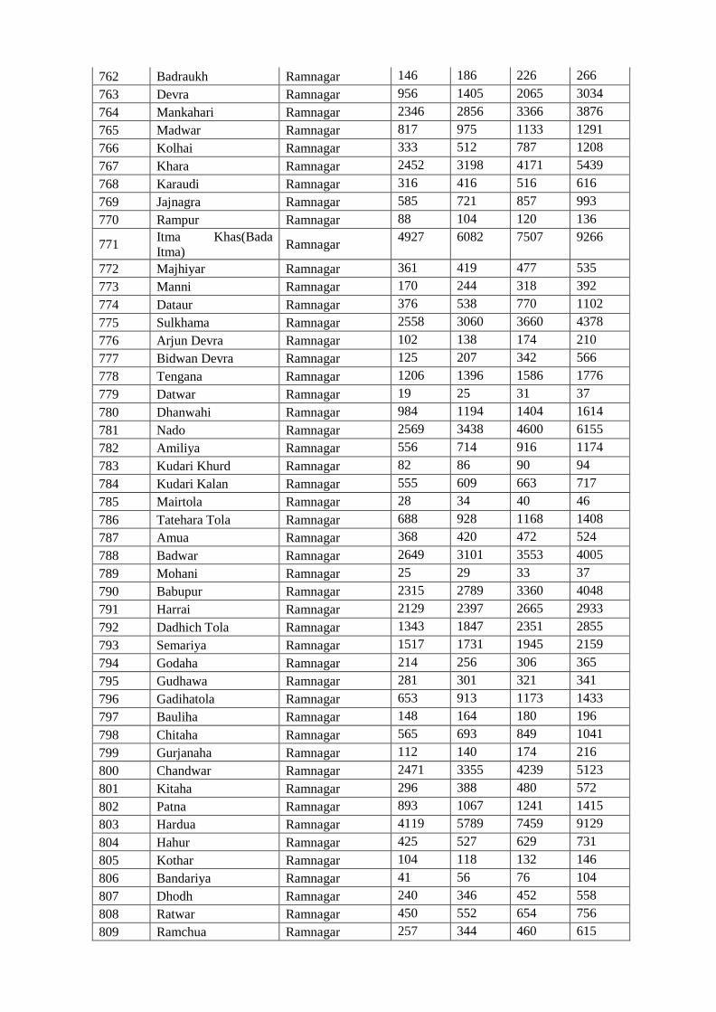
762 Badraukh Ramnagar 146 186 226 266
763 Devra Ramnagar 956 1405 2065 3034
764 Mankahari Ramnagar 2346 2856 3366 3876
765 Madwar Ramnagar 817 975 1133 1291
766 Kolhai Ramnagar 333 512 787 1208
767 Khara Ramnagar 2452 3198 4171 5439
768 Karaudi Ramnagar 316 416 516 616
769 Jajnagra Ramnagar 585 721 857 993
770 Rampur Ramnagar 88 104 120 136
771 Itma Khas(Bada
Itma) Ramnagar
4927 6082 7507 9266
772 Majhiyar Ramnagar 361 419 477 535
773 Manni Ramnagar 170 244 318 392
774 Dataur Ramnagar 376 538 770 1102
775 Sulkhama Ramnagar 2558 3060 3660 4378
776 Arjun Devra Ramnagar 102 138 174 210
777 Bidwan Devra Ramnagar 125 207 342 566
778 Tengana Ramnagar 1206 1396 1586 1776
779 Datwar Ramnagar 19 25 31 37
780 Dhanwahi Ramnagar 984 1194 1404 1614
781 Nado Ramnagar 2569 3438 4600 6155
782 Amiliya Ramnagar 556 714 916 1174
783 Kudari Khurd Ramnagar 82 86 90 94
784 Kudari Kalan Ramnagar 555 609 663 717
785 Mairtola Ramnagar 28 34 40 46
786 Tatehara Tola Ramnagar 688 928 1168 1408
787 Amua Ramnagar 368 420 472 524
788 Badwar Ramnagar 2649 3101 3553 4005
789 Mohani Ramnagar 25 29 33 37
790 Babupur Ramnagar 2315 2789 3360 4048
791 Harrai Ramnagar 2129 2397 2665 2933
792 Dadhich Tola Ramnagar 1343 1847 2351 2855
793 Semariya Ramnagar 1517 1731 1945 2159
794 Godaha Ramnagar 214 256 306 365
795 Gudhawa Ramnagar 281 301 321 341
796 Gadihatola Ramnagar 653 913 1173 1433
797 Bauliha Ramnagar 148 164 180 196
798 Chitaha Ramnagar 565 693 849 1041
799 Gurjanaha Ramnagar 112 140 174 216
800 Chandwar Ramnagar 2471 3355 4239 5123
801 Kitaha Ramnagar 296 388 480 572
802 Patna Ramnagar 893 1067 1241 1415
803 Hardua Ramnagar 4119 5789 7459 9129
804 Hahur Ramnagar 425 527 629 731
805 Kothar Ramnagar 104 118 132 146
806 Bandariya Ramnagar 41 56 76 104
807 Dhodh Ramnagar 240 346 452 558
808 Ratwar Ramnagar 450 552 654 756
809 Ramchua Ramnagar 257 344 460 615
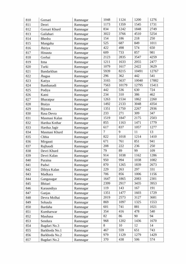
810 Gorsari Ramnagar 1048 1124 1200 1276
811 Deori Ramnagar 1173 1359 1545 1731
812 Gorsari Khurd Ramnagar 834 1242 1848 2749
813 Gailahari Ramnagar 3022 3766 4510 5254
814 Bhedra Ramnagar 154 186 218 250
815 Mungaha Ramnagar 525 687 849 1011
816 Jhiriya Ramnagar 422 498 574 650
817 Hinauta Ramnagar 609 733 857 981
818 Gorhai Ramnagar 2123 2835 3547 4259
819 Itma Ramnagar 1211 1633 2055 2477
820 Turki Ramnagar 1079 1617 2422 3629
821 Bandarkhan Ramnagar 5939 8215 10491 12767
822 Jhagaa Ramnagar 296 362 442 541
823 Katiya Ramnagar 3165 5637 10040 17882
824 Bamhanadi Ramnagar 7563 10179 12795 15411
825 Podiya Ramnagar 442 536 630 724
826 Katni Ramnagar 234 310 386 462
827 Bharatpur Ramnagar 1263 1534 1862 2260
828 Btaiya Ramnagar 1492 2133 3048 4354
829 Bijoura Ramnagar 1351 1750 2267 2936
830 Rasa Devra Ramnagar 233 271 309 347
831 Masmasi Kalan Ramnagar 1519 1847 2175 2503
832 Hardua Kothar Ramnagar 855 1163 1471 1779
833 Hardua Jagir Ramnagar 617 837 1057 1277
834 Masmasi Khurd Ramnagar 7 9 11 13
835 Chhia Ramnagar 822 1018 1214 1410
836 Mirgauti Ramnagar 671 761 851 941
837 Rajhaudi Ramnagar 208 222 236 250
838 Devri Khurd Ramnagar 79 89 99 109
839 Devri Kalan Ramnagar 914 1038 1162 1286
840 Puraina Ramnagar 950 994 1038 1082
841 Padwi Ramnagar 870 1265 1839 2673
842 Dihiya Kalan Ramnagar 229 263 297 331
843 Madkara Ramnagar 706 856 1006 1156
844 Gangasagar Ramnagar 1647 1865 2083 2301
845 Bhitari Ramnagar 2399 2917 3435 3953
846 Karaundiya Ramnagar 119 143 167 191
847 Ganjas Ramnagar 1351 1477 1603 1729
848 Devra Molhai Ramnagar 2019 2573 3127 3681
849 Sohaula Ramnagar 869 1097 1325 1553
850 Bardaha Ramnagar 601 741 881 1021
851 Kumharwar Ramnagar 354 416 478 540
852 Mauhasa Ramnagar 82 86 90 94
853 Sendura Ramnagar 968 1202 1436 1670
854 Bagdari No.3 Ramnagar 8 10 12 14
855 Barkhoda No.1 Ramnagar 467 559 651 743
856 Barkhoda No.2 Ramnagar 979 1129 1279 1429
857 Bagdari No.2 Ramnagar 370 438 506 574
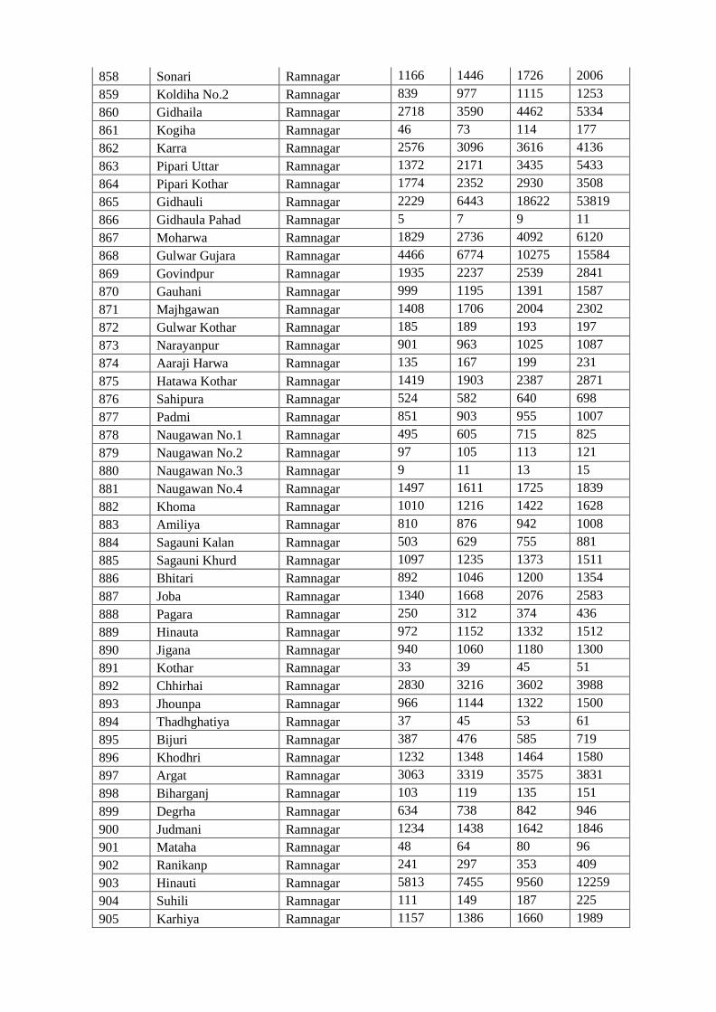
858 Sonari Ramnagar 1166 1446 1726 2006
859 Koldiha No.2 Ramnagar 839 977 1115 1253
860 Gidhaila Ramnagar 2718 3590 4462 5334
861 Kogiha Ramnagar 46 73 114 177
862 Karra Ramnagar 2576 3096 3616 4136
863 Pipari Uttar Ramnagar 1372 2171 3435 5433
864 Pipari Kothar Ramnagar 1774 2352 2930 3508
865 Gidhauli Ramnagar 2229 6443 18622 53819
866 Gidhaula Pahad Ramnagar 5 7 9 11
867 Moharwa Ramnagar 1829 2736 4092 6120
868 Gulwar Gujara Ramnagar 4466 6774 10275 15584
869 Govindpur Ramnagar 1935 2237 2539 2841
870 Gauhani Ramnagar 999 1195 1391 1587
871 Majhgawan Ramnagar 1408 1706 2004 2302
872 Gulwar Kothar Ramnagar 185 189 193 197
873 Narayanpur Ramnagar 901 963 1025 1087
874 Aaraji Harwa Ramnagar 135 167 199 231
875 Hatawa Kothar Ramnagar 1419 1903 2387 2871
876 Sahipura Ramnagar 524 582 640 698
877 Padmi Ramnagar 851 903 955 1007
878 Naugawan No.1 Ramnagar 495 605 715 825
879 Naugawan No.2 Ramnagar 97 105 113 121
880 Naugawan No.3 Ramnagar 9 11 13 15
881 Naugawan No.4 Ramnagar 1497 1611 1725 1839
882 Khoma Ramnagar 1010 1216 1422 1628
883 Amiliya Ramnagar 810 876 942 1008
884 Sagauni Kalan Ramnagar 503 629 755 881
885 Sagauni Khurd Ramnagar 1097 1235 1373 1511
886 Bhitari Ramnagar 892 1046 1200 1354
887 Joba Ramnagar 1340 1668 2076 2583
888 Pagara Ramnagar 250 312 374 436
889 Hinauta Ramnagar 972 1152 1332 1512
890 Jigana Ramnagar 940 1060 1180 1300
891 Kothar Ramnagar 33 39 45 51
892 Chhirhai Ramnagar 2830 3216 3602 3988
893 Jhounpa Ramnagar 966 1144 1322 1500
894 Thadhghatiya Ramnagar 37 45 53 61
895 Bijuri Ramnagar 387 476 585 719
896 Khodhri Ramnagar 1232 1348 1464 1580
897 Argat Ramnagar 3063 3319 3575 3831
898 Biharganj Ramnagar 103 119 135 151
899 Degrha Ramnagar 634 738 842 946
900 Judmani Ramnagar 1234 1438 1642 1846
901 Mataha Ramnagar 48 64 80 96
902 Ranikanp Ramnagar 241 297 353 409
903 Hinauti Ramnagar 5813 7455 9560 12259
904 Suhili Ramnagar 111 149 187 225
905 Karhiya Ramnagar 1157 1386 1660 1989
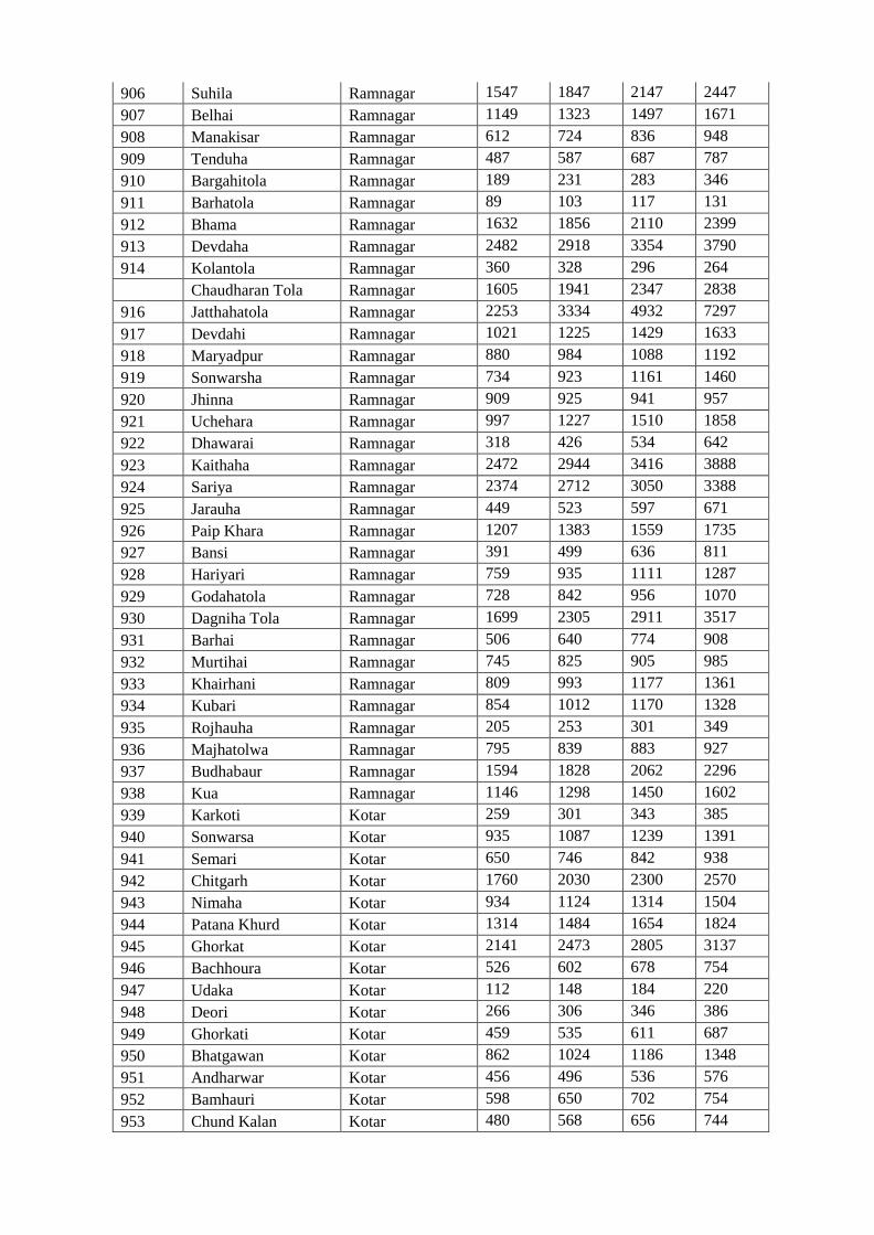
906 Suhila Ramnagar 1547 1847 2147 2447
907 Belhai Ramnagar 1149 1323 1497 1671
908 Manakisar Ramnagar 612 724 836 948
909 Tenduha Ramnagar 487 587 687 787
910 Bargahitola Ramnagar 189 231 283 346
911 Barhatola Ramnagar 89 103 117 131
912 Bhama Ramnagar 1632 1856 2110 2399
913 Devdaha Ramnagar 2482 2918 3354 3790
914 Kolantola Ramnagar 360 328 296 264
Chaudharan Tola Ramnagar 1605 1941 2347 2838
916 Jatthahatola Ramnagar 2253 3334 4932 7297
917 Devdahi Ramnagar 1021 1225 1429 1633
918 Maryadpur Ramnagar 880 984 1088 1192
919 Sonwarsha Ramnagar 734 923 1161 1460
920 Jhinna Ramnagar 909 925 941 957
921 Uchehara Ramnagar 997 1227 1510 1858
922 Dhawarai Ramnagar 318 426 534 642
923 Kaithaha Ramnagar 2472 2944 3416 3888
924 Sariya Ramnagar 2374 2712 3050 3388
925 Jarauha Ramnagar 449 523 597 671
926 Paip Khara Ramnagar 1207 1383 1559 1735
927 Bansi Ramnagar 391 499 636 811
928 Hariyari Ramnagar 759 935 1111 1287
929 Godahatola Ramnagar 728 842 956 1070
930 Dagniha Tola Ramnagar 1699 2305 2911 3517
931 Barhai Ramnagar 506 640 774 908
932 Murtihai Ramnagar 745 825 905 985
933 Khairhani Ramnagar 809 993 1177 1361
934 Kubari Ramnagar 854 1012 1170 1328
935 Rojhauha Ramnagar 205 253 301 349
936 Majhatolwa Ramnagar 795 839 883 927
937 Budhabaur Ramnagar 1594 1828 2062 2296
938 Kua Ramnagar 1146 1298 1450 1602
939 Karkoti Kotar 259 301 343 385
940 Sonwarsa Kotar 935 1087 1239 1391
941 Semari Kotar 650 746 842 938
942 Chitgarh Kotar 1760 2030 2300 2570
943 Nimaha Kotar 934 1124 1314 1504
944 Patana Khurd Kotar 1314 1484 1654 1824
945 Ghorkat Kotar 2141 2473 2805 3137
946 Bachhoura Kotar 526 602 678 754
947 Udaka Kotar 112 148 184 220
948 Deori Kotar 266 306 346 386
949 Ghorkati Kotar 459 535 611 687
950 Bhatgawan Kotar 862 1024 1186 1348
951 Andharwar Kotar 456 496 536 576
952 Bamhauri Kotar 598 650 702 754
953 Chund Kalan Kotar 480 568 656 744
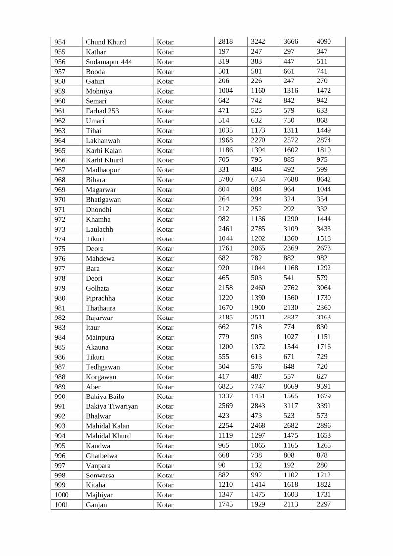
954 Chund Khurd Kotar 2818 3242 3666 4090
955 Kathar Kotar 197 247 297 347
956 Sudamapur 444 Kotar 319 383 447 511
957 Booda Kotar 501 581 661 741
958 Gahiri Kotar 206 226 247 270
959 Mohniya Kotar 1004 1160 1316 1472
960 Semari Kotar 642 742 842 942
961 Farhad 253 Kotar 471 525 579 633
962 Umari Kotar 514 632 750 868
963 Tihai Kotar 1035 1173 1311 1449
964 Lakhanwah Kotar 1968 2270 2572 2874
965 Karhi Kalan Kotar 1186 1394 1602 1810
966 Karhi Khurd Kotar 705 795 885 975
967 Madhaopur Kotar 331 404 492 599
968 Bihara Kotar 5780 6734 7688 8642
969 Magarwar Kotar 804 884 964 1044
970 Bhatigawan Kotar 264 294 324 354
971 Dhondhi Kotar 212 252 292 332
972 Khamha Kotar 982 1136 1290 1444
973 Laulachh Kotar 2461 2785 3109 3433
974 Tikuri Kotar 1044 1202 1360 1518
975 Deora Kotar 1761 2065 2369 2673
976 Mahdewa Kotar 682 782 882 982
977 Bara Kotar 920 1044 1168 1292
978 Deori Kotar 465 503 541 579
979 Golhata Kotar 2158 2460 2762 3064
980 Piprachha Kotar 1220 1390 1560 1730
981 Thathaura Kotar 1670 1900 2130 2360
982 Rajarwar Kotar 2185 2511 2837 3163
983 Itaur Kotar 662 718 774 830
984 Mainpura Kotar 779 903 1027 1151
985 Akauna Kotar 1200 1372 1544 1716
986 Tikuri Kotar 555 613 671 729
987 Tedhgawan Kotar 504 576 648 720
988 Korgawan Kotar 417 487 557 627
989 Aber Kotar 6825 7747 8669 9591
990 Bakiya Bailo Kotar 1337 1451 1565 1679
991 Bakiya Tiwariyan Kotar 2569 2843 3117 3391
992 Bhalwar Kotar 423 473 523 573
993 Mahidal Kalan Kotar 2254 2468 2682 2896
994 Mahidal Khurd Kotar 1119 1297 1475 1653
995 Kandwa Kotar 965 1065 1165 1265
996 Ghatbelwa Kotar 668 738 808 878
997 Vanpara Kotar 90 132 192 280
998 Sonwarsa Kotar 882 992 1102 1212
999 Kitaha Kotar 1210 1414 1618 1822
1000 Majhiyar Kotar 1347 1475 1603 1731
1001 Ganjan Kotar 1745 1929 2113 2297
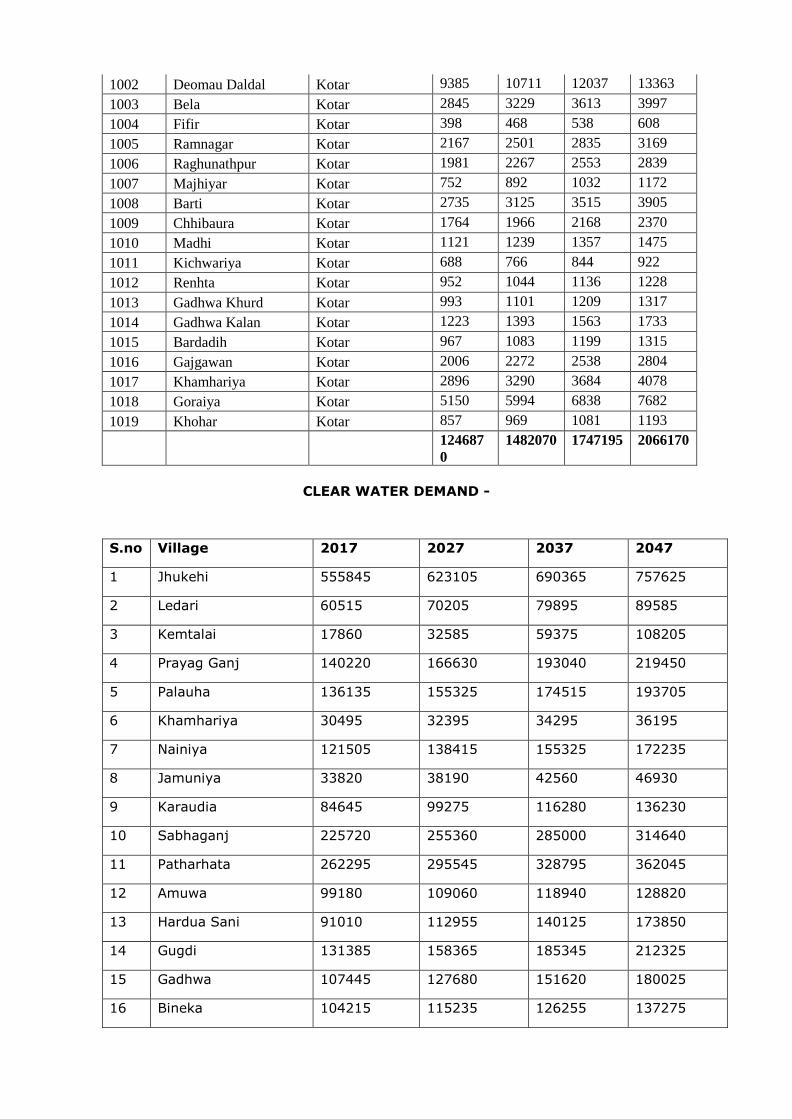
1002 Deomau Daldal Kotar 9385 10711 12037 13363
1003 Bela Kotar 2845 3229 3613 3997
1004 Fifir Kotar 398 468 538 608
1005 Ramnagar Kotar 2167 2501 2835 3169
1006 Raghunathpur Kotar 1981 2267 2553 2839
1007 Majhiyar Kotar 752 892 1032 1172
1008 Barti Kotar 2735 3125 3515 3905
1009 Chhibaura Kotar 1764 1966 2168 2370
1010 Madhi Kotar 1121 1239 1357 1475
1011 Kichwariya Kotar 688 766 844 922
1012 Renhta Kotar 952 1044 1136 1228
1013 Gadhwa Khurd Kotar 993 1101 1209 1317
1014 Gadhwa Kalan Kotar 1223 1393 1563 1733
1015 Bardadih Kotar 967 1083 1199 1315
1016 Gajgawan Kotar 2006 2272 2538 2804
1017 Khamhariya Kotar 2896 3290 3684 4078
1018 Goraiya Kotar 5150 5994 6838 7682
1019 Khohar Kotar 857 969 1081 1193
124687
0
1482070 1747195 2066170
CLEAR WATER DEMAND -
S.no Village 2017 2027 2037 2047
1 Jhukehi 555845 623105 690365 757625
2 Ledari 60515 70205 79895 89585
3 Kemtalai 17860 32585 59375 108205
4 Prayag Ganj 140220 166630 193040 219450
5 Palauha 136135 155325 174515 193705
6 Khamhariya 30495 32395 34295 36195
7 Nainiya 121505 138415 155325 172235
8 Jamuniya 33820 38190 42560 46930
9 Karaudia 84645 99275 116280 136230
10 Sabhaganj 225720 255360 285000 314640
11 Patharhata 262295 295545 328795 362045
12 Amuwa 99180 109060 118940 128820
13 Hardua Sani 91010 112955 140125 173850
14 Gugdi 131385 158365 185345 212325
15 Gadhwa 107445 127680 151620 180025
16 Bineka 104215 115235 126255 137275
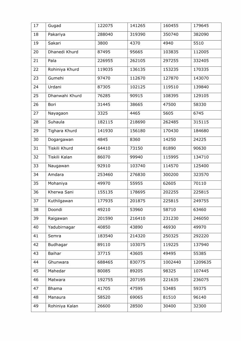
17 Gugad 122075 141265 160455 179645
18 Pakariya 288040 319390 350740 382090
19 Sakari 3800 4370 4940 5510
20 Dhanedi Khurd 87495 95665 103835 112005
21 Pala 226955 262105 297255 332405
22 Rohiniya Khurd 119035 136135 153235 170335
23 Gumehi 97470 112670 127870 143070
24 Urdani 87305 102125 119510 139840
25 Dhanwahi Khurd 76285 90915 108395 129105
26 Bori 31445 38665 47500 58330
27 Nayagaon 3325 4465 5605 6745
28 Suhaula 182115 218690 262485 315115
29 Tighara Khurd 141930 156180 170430 184680
30 Dogargawan 4845 8360 14250 24225
31 Tiskili Khurd 64410 73150 81890 90630
32 Tiskili Kalan 86070 99940 115995 134710
33 Naugawan 92910 103740 114570 125400
34 Amdara 253460 276830 300200 323570
35 Mohaniya 49970 55955 62605 70110
36 Kherwa Sani 155135 178695 202255 225815
37 Kuthilgawan 177935 201875 225815 249755
38 Doondi 49210 53960 58710 63460
39 Raigawan 201590 216410 231230 246050
40 Yadubirnagar 40850 43890 46930 49970
41 Semra 183540 214320 250325 292220
42 Budhagar 89110 103075 119225 137940
43 Baihar 37715 43605 49495 55385
44 Ghunwara 688465 830775 1002440 1209635
45 Mahedar 80085 89205 98325 107445
46 Matwara 192755 207195 221635 236075
47 Bhama 41705 47595 53485 59375
48 Manaura 58520 69065 81510 96140
49 Rohiniya Kalan 26600 28500 30400 32300
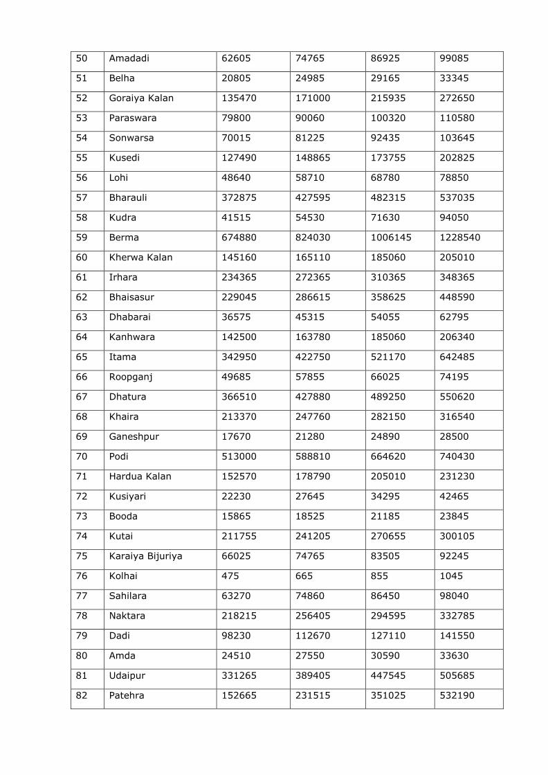
50 Amadadi 62605 74765 86925 99085
51 Belha 20805 24985 29165 33345
52 Goraiya Kalan 135470 171000 215935 272650
53 Paraswara 79800 90060 100320 110580
54 Sonwarsa 70015 81225 92435 103645
55 Kusedi 127490 148865 173755 202825
56 Lohi 48640 58710 68780 78850
57 Bharauli 372875 427595 482315 537035
58 Kudra 41515 54530 71630 94050
59 Berma 674880 824030 1006145 1228540
60 Kherwa Kalan 145160 165110 185060 205010
61 Irhara 234365 272365 310365 348365
62 Bhaisasur 229045 286615 358625 448590
63 Dhabarai 36575 45315 54055 62795
64 Kanhwara 142500 163780 185060 206340
65 Itama 342950 422750 521170 642485
66 Roopganj 49685 57855 66025 74195
67 Dhatura 366510 427880 489250 550620
68 Khaira 213370 247760 282150 316540
69 Ganeshpur 17670 21280 24890 28500
70 Podi 513000 588810 664620 740430
71 Hardua Kalan 152570 178790 205010 231230
72 Kusiyari 22230 27645 34295 42465
73 Booda 15865 18525 21185 23845
74 Kutai 211755 241205 270655 300105
75 Karaiya Bijuriya 66025 74765 83505 92245
76 Kolhai 475 665 855 1045
77 Sahilara 63270 74860 86450 98040
78 Naktara 218215 256405 294595 332785
79 Dadi 98230 112670 127110 141550
80 Amda 24510 27550 30590 33630
81 Udaipur 331265 389405 447545 505685
82 Patehra 152665 231515 351025 532190
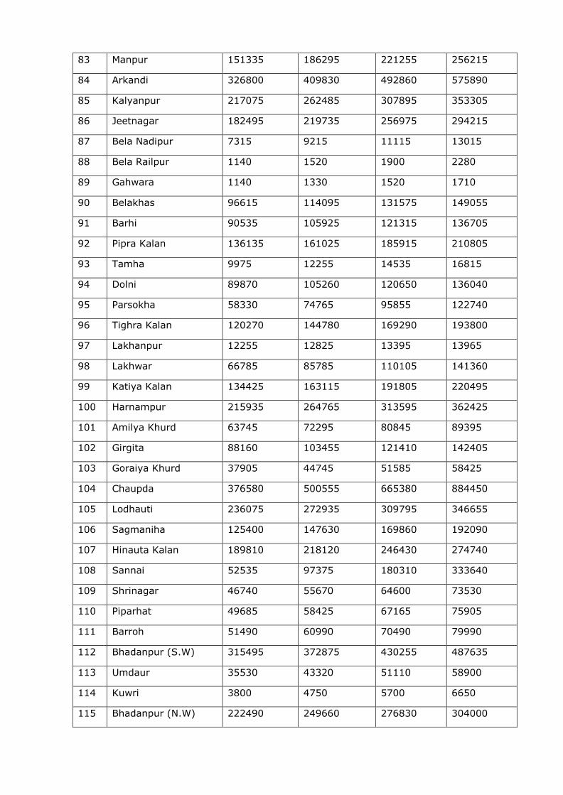
83 Manpur 151335 186295 221255 256215
84 Arkandi 326800 409830 492860 575890
85 Kalyanpur 217075 262485 307895 353305
86 Jeetnagar 182495 219735 256975 294215
87 Bela Nadipur 7315 9215 11115 13015
88 Bela Railpur 1140 1520 1900 2280
89 Gahwara 1140 1330 1520 1710
90 Belakhas 96615 114095 131575 149055
91 Barhi 90535 105925 121315 136705
92 Pipra Kalan 136135 161025 185915 210805
93 Tamha 9975 12255 14535 16815
94 Dolni 89870 105260 120650 136040
95 Parsokha 58330 74765 95855 122740
96 Tighra Kalan 120270 144780 169290 193800
97 Lakhanpur 12255 12825 13395 13965
98 Lakhwar 66785 85785 110105 141360
99 Katiya Kalan 134425 163115 191805 220495
100 Harnampur 215935 264765 313595 362425
101 Amilya Khurd 63745 72295 80845 89395
102 Girgita 88160 103455 121410 142405
103 Goraiya Khurd 37905 44745 51585 58425
104 Chaupda 376580 500555 665380 884450
105 Lodhauti 236075 272935 309795 346655
106 Sagmaniha 125400 147630 169860 192090
107 Hinauta Kalan 189810 218120 246430 274740
108 Sannai 52535 97375 180310 333640
109 Shrinagar 46740 55670 64600 73530
110 Piparhat 49685 58425 67165 75905
111 Barroh 51490 60990 70490 79990
112 Bhadanpur (S.W) 315495 372875 430255 487635
113 Umdaur 35530 43320 51110 58900
114 Kuwri 3800 4750 5700 6650
115 Bhadanpur (N.W) 222490 249660 276830 304000
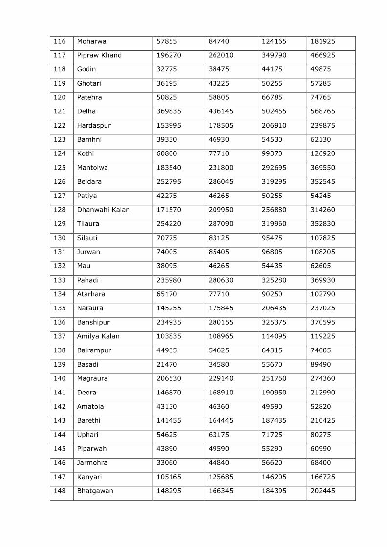
116 Moharwa 57855 84740 124165 181925
117 Pipraw Khand 196270 262010 349790 466925
118 Godin 32775 38475 44175 49875
119 Ghotari 36195 43225 50255 57285
120 Patehra 50825 58805 66785 74765
121 Delha 369835 436145 502455 568765
122 Hardaspur 153995 178505 206910 239875
123 Bamhni 39330 46930 54530 62130
124 Kothi 60800 77710 99370 126920
125 Mantolwa 183540 231800 292695 369550
126 Beldara 252795 286045 319295 352545
127 Patiya 42275 46265 50255 54245
128 Dhanwahi Kalan 171570 209950 256880 314260
129 Tilaura 254220 287090 319960 352830
130 Silauti 70775 83125 95475 107825
131 Jurwan 74005 85405 96805 108205
132 Mau 38095 46265 54435 62605
133 Pahadi 235980 280630 325280 369930
134 Atarhara 65170 77710 90250 102790
135 Naraura 145255 175845 206435 237025
136 Banshipur 234935 280155 325375 370595
137 Amilya Kalan 103835 108965 114095 119225
138 Balrampur 44935 54625 64315 74005
139 Basadi 21470 34580 55670 89490
140 Magraura 206530 229140 251750 274360
141 Deora 146870 168910 190950 212990
142 Amatola 43130 46360 49590 52820
143 Barethi 141455 164445 187435 210425
144 Uphari 54625 63175 71725 80275
145 Piparwah 43890 49590 55290 60990
146 Jarmohra 33060 44840 56620 68400
147 Kanyari 105165 125685 146205 166725
148 Bhatgawan 148295 166345 184395 202445
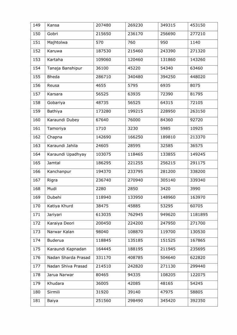
149 Kansa 207480 269230 349315 453150
150 Gobri 215650 236170 256690 277210
151 Majhtolwa 570 760 950 1140
152 Karuwa 187530 215460 243390 271320
153 Kartaha 109060 120460 131860 143260
154 Tanaja Banshipur 36100 45220 54340 63460
155 Bheda 286710 340480 394250 448020
156 Reusa 4655 5795 6935 8075
157 Karsara 56525 63935 72390 81795
158 Gobariya 48735 56525 64315 72105
159 Bathiya 173280 199215 228950 263150
160 Karaundi Dubey 67640 76000 84360 92720
161 Tamoriya 1710 3230 5985 10925
162 Chapna 142690 166250 189810 213370
163 Karaundi Jahila 24605 28595 32585 36575
164 Karaundi Upadhyay 103075 118465 133855 149245
165 Jamtal 186295 221255 256215 291175
166 Kanchanpur 194370 233795 281200 338200
167 Rigra 236740 270940 305140 339340
168 Mudi 2280 2850 3420 3990
169 Dubehi 118940 133950 148960 163970
170 Katiya Khurd 38475 45885 53295 60705
171 Jariyari 613035 762945 949620 1181895
172 Karaiya Deori 200450 224200 247950 271700
173 Narwar Kalan 98040 108870 119700 130530
174 Buderua 118845 135185 151525 167865
175 Karaundi Kapnadan 164445 188195 211945 235695
176 Nadan Sharda Prasad 331170 408785 504640 622820
177 Nadan Shiva Prasad 214510 242820 271130 299440
178 Jarua Narwar 80465 94335 108205 122075
179 Khudara 36005 42085 48165 54245
180 Sirmili 31920 39140 47975 58805
181 Baiya 251560 298490 345420 392350
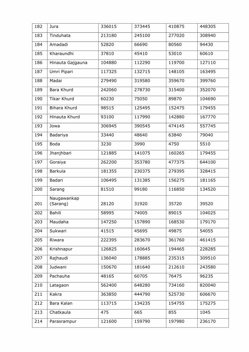
182 Jura 336015 373445 410875 448305
183 Tinduhata 213180 245100 277020 308940
184 Amadadi 52820 66690 80560 94430
185 Kharaundhi 37810 45410 53010 60610
186 Hinauta Gajgauna 104880 112290 119700 127110
187 Umri Pipari 117325 132715 148105 163495
188 Madai 279490 319580 359670 399760
189 Bara Khurd 242060 278730 315400 352070
190 Tikar Khurd 60230 75050 89870 104690
191 Bihara Khurd 98515 125495 152475 179455
192 Hinauta Khurd 93100 117990 142880 167770
193 Jowa 306945 390545 474145 557745
194 Badariya 33440 48640 63840 79040
195 Boda 3230 3990 4750 5510
196 Jhanjhbari 121885 141075 160265 179455
197 Goraiya 262200 353780 477375 644100
198 Barkula 181355 230375 279395 328415
199 Badari 106495 131385 156275 181165
200 Sarang 81510 99180 116850 134520
201
Naugawankap
(Sarang) 28120 31920 35720 39520
202 Bahili 58995 74005 89015 104025
203 Maudaha 147250 157890 168530 179170
204 Sukwari 41515 45695 49875 54055
205 Riwara 222395 283670 361760 461415
206 Krishnapur 126825 160645 194465 228285
207 Rajhaudi 136040 178885 235315 309510
208 Judwani 150670 181640 212610 243580
209 Pachauha 48165 60705 76475 96235
210 Latagaon 562400 648280 734160 820040
211 Kakra 363850 444790 525730 606670
212 Bara Kalan 113715 134235 154755 175275
213 Chatkaula 475 665 855 1045
214 Parasrampur 121600 159790 197980 236170

215 Deori 202445 239875 277305 314735
216 Badera 236930 270560 304190 337820
217 Majhiyar 570 760 950 1140
218 Bharewa 103455 127680 157510 194370
219 Guguwar 11020 15200 19380 23560
220 Sadhera 144590 161690 178790 195890
221 Salaiya 267995 315115 362235 409355
222 Bihara Kalan 136610 174610 223155 285095
223 Tikar Kalan 60610 68400 76190 83980
224 Ajmain 443840 519080 594320 669560
225 Bhadai 48165 53865 60325 67545
226 Naugawankap 10925 11875 12825 13775
227 Bhatewara 118085 141455 164825 188195
228 Bandhi 133950 159980 186010 212040
229 Ghorbai 179075 205865 232655 259445
230 Dhanedi Kalan 88635 98705 108775 118845
231 Amatara 243865 287945 332025 376105
232 Bishnupur 72580 83790 96615 111435
233 Banjariya 74670 81320 87970 94620
234 Mand 49115 61370 76570 95475
235 Dharampura 84930 92340 99750 107160
236 Amiliya 215270 242630 269990 297350
237 Koylari 141835 169005 196175 223345
238 Kudwa 200640 234460 273790 319865
239 Majhgawan 342475 421895 519745 640205
240 Dhanwahi 293740 338390 383040 427690
241 Umri Paila 260300 338960 417620 496280
242 Sonwari 822035 911905 1001775 1091645
243 Jhanda Tola 117230 136610 159125 185345
244 Sukhsena 3325 4085 4845 5605
245 Kurehi 63745 80275 100985 127015
246 Maharaj 37050 51965 72865 102125
247 Majhgawan 28975 39330 53295 72200
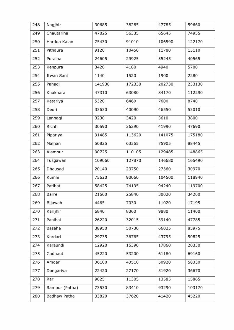
248 Nagjhir 30685 38285 47785 59660
249 Chautariha 47025 56335 65645 74955
250 Hardua Kalan 75430 91010 106590 122170
251 Pithaura 9120 10450 11780 13110
252 Puraina 24605 29925 35245 40565
253 Kenpura 3420 4180 4940 5700
254 Itwan Sani 1140 1520 1900 2280
255 Pahadi 141930 172330 202730 233130
256 Khakhara 47310 63080 84170 112290
257 Katariya 5320 6460 7600 8740
258 Deori 33630 40090 46550 53010
259 Lanhagi 3230 3420 3610 3800
260 Richhi 30590 36290 41990 47690
261 Pipariya 91485 113620 141075 175180
262 Malhan 50825 63365 75905 88445
263 Alampur 90725 110105 129485 148865
264 Tusgawan 109060 127870 146680 165490
265 Dhausad 20140 23750 27360 30970
266 Kumhi 75620 90060 104500 118940
267 Patihat 58425 74195 94240 119700
268 Barre 21660 25840 30020 34200
269 Bijawah 4465 7030 11020 17195
270 Karijhir 6840 8360 9880 11400
271 Panihai 26220 32015 39140 47785
272 Basaha 38950 50730 66025 85975
273 Kordari 29735 36765 43795 50825
274 Karaundi 12920 15390 17860 20330
275 Gadhaut 45220 53200 61180 69160
276 Amdari 36100 43510 50920 58330
277 Dongariya 22420 27170 31920 36670
278 Rar 9025 11305 13585 15865
279 Rampur (Patha) 73530 83410 93290 103170
280 Badhaw Patha 33820 37620 41420 45220
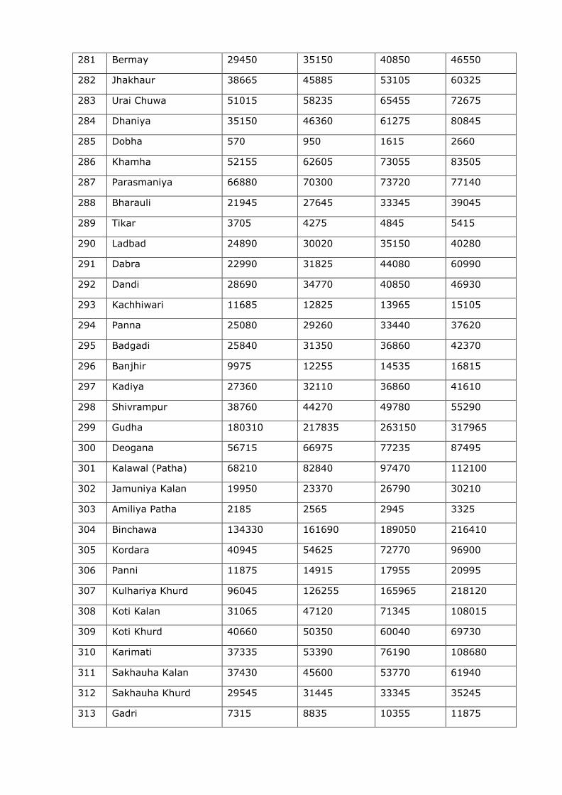
281 Bermay 29450 35150 40850 46550
282 Jhakhaur 38665 45885 53105 60325
283 Urai Chuwa 51015 58235 65455 72675
284 Dhaniya 35150 46360 61275 80845
285 Dobha 570 950 1615 2660
286 Khamha 52155 62605 73055 83505
287 Parasmaniya 66880 70300 73720 77140
288 Bharauli 21945 27645 33345 39045
289 Tikar 3705 4275 4845 5415
290 Ladbad 24890 30020 35150 40280
291 Dabra 22990 31825 44080 60990
292 Dandi 28690 34770 40850 46930
293 Kachhiwari 11685 12825 13965 15105
294 Panna 25080 29260 33440 37620
295 Badgadi 25840 31350 36860 42370
296 Banjhir 9975 12255 14535 16815
297 Kadiya 27360 32110 36860 41610
298 Shivrampur 38760 44270 49780 55290
299 Gudha 180310 217835 263150 317965
300 Deogana 56715 66975 77235 87495
301 Kalawal (Patha) 68210 82840 97470 112100
302 Jamuniya Kalan 19950 23370 26790 30210
303 Amiliya Patha 2185 2565 2945 3325
304 Binchawa 134330 161690 189050 216410
305 Kordara 40945 54625 72770 96900
306 Panni 11875 14915 17955 20995
307 Kulhariya Khurd 96045 126255 165965 218120
308 Koti Kalan 31065 47120 71345 108015
309 Koti Khurd 40660 50350 60040 69730
310 Karimati 37335 53390 76190 108680
311 Sakhauha Kalan 37430 45600 53770 61940
312 Sakhauha Khurd 29545 31445 33345 35245
313 Gadri 7315 8835 10355 11875
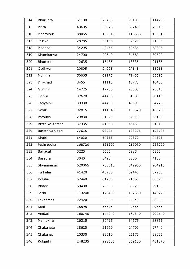
314 Bhuruhra 61180 75430 93100 114760
315 Pipra 43605 53675 63745 73815
316 Mahrajpur 88065 102315 116565 130815
317 Jhiriya 28785 33155 37525 41895
318 Madphai 34295 42465 50635 58805
319 Khamhariya 24700 29640 34580 39520
320 Bhummra 12635 15485 18335 21185
321 Gadhwa 20805 24225 27645 31065
322 Mohnna 50065 61275 72485 83695
323 Dhausad 8455 11115 13775 16435
324 Gunjhir 14725 17765 20805 23845
325 Tighra 37620 44460 51300 58140
326 Tatiyajhir 39330 44460 49590 54720
327 Semri 92815 111340 133570 160265
328 Patouda 29830 31920 34010 36100
329 Brethiya Kothar 37335 41895 46455 51015
330 Barethiya Ubari 77615 93005 108395 123785
331 Khairi 64030 67355 70870 74575
332 Pathraudha 168720 191900 215080 238260
333 Bairagal 5225 5605 5985 6365
334 Basaura 3040 3420 3800 4180
335 Shyamnagar 620065 735015 849965 964915
336 Turkaha 41420 46930 52440 57950
337 Koluha 52440 61750 71060 80370
338 Bhitari 68400 78660 88920 99180
339 Jakhi 113240 125400 137560 149720
340 Lakhamad 22420 26030 29640 33250
341 Koni 28595 35625 42655 49685
342 Amdari 160740 174040 187340 200640
343 Majhokhar 26315 30495 34675 38855
344 Chakahata 18620 21660 24700 27740
345 Chakahat 20330 22610 25175 28025
346 Kulgarhi 248235 298585 359100 431870
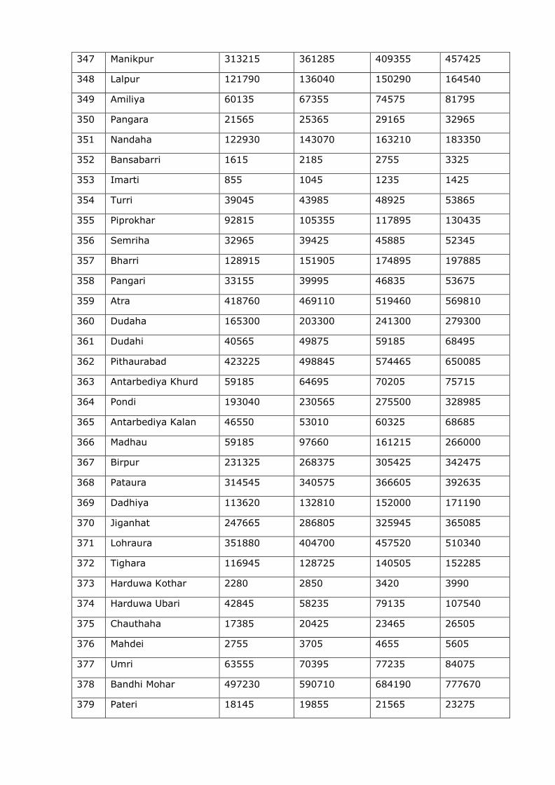
347 Manikpur 313215 361285 409355 457425
348 Lalpur 121790 136040 150290 164540
349 Amiliya 60135 67355 74575 81795
350 Pangara 21565 25365 29165 32965
351 Nandaha 122930 143070 163210 183350
352 Bansabarri 1615 2185 2755 3325
353 Imarti 855 1045 1235 1425
354 Turri 39045 43985 48925 53865
355 Piprokhar 92815 105355 117895 130435
356 Semriha 32965 39425 45885 52345
357 Bharri 128915 151905 174895 197885
358 Pangari 33155 39995 46835 53675
359 Atra 418760 469110 519460 569810
360 Dudaha 165300 203300 241300 279300
361 Dudahi 40565 49875 59185 68495
362 Pithaurabad 423225 498845 574465 650085
363 Antarbediya Khurd 59185 64695 70205 75715
364 Pondi 193040 230565 275500 328985
365 Antarbediya Kalan 46550 53010 60325 68685
366 Madhau 59185 97660 161215 266000
367 Birpur 231325 268375 305425 342475
368 Pataura 314545 340575 366605 392635
369 Dadhiya 113620 132810 152000 171190
370 Jiganhat 247665 286805 325945 365085
371 Lohraura 351880 404700 457520 510340
372 Tighara 116945 128725 140505 152285
373 Harduwa Kothar 2280 2850 3420 3990
374 Harduwa Ubari 42845 58235 79135 107540
375 Chauthaha 17385 20425 23465 26505
376 Mahdei 2755 3705 4655 5605
377 Umri 63555 70395 77235 84075
378 Bandhi Mohar 497230 590710 684190 777670
379 Pateri 18145 19855 21565 23275
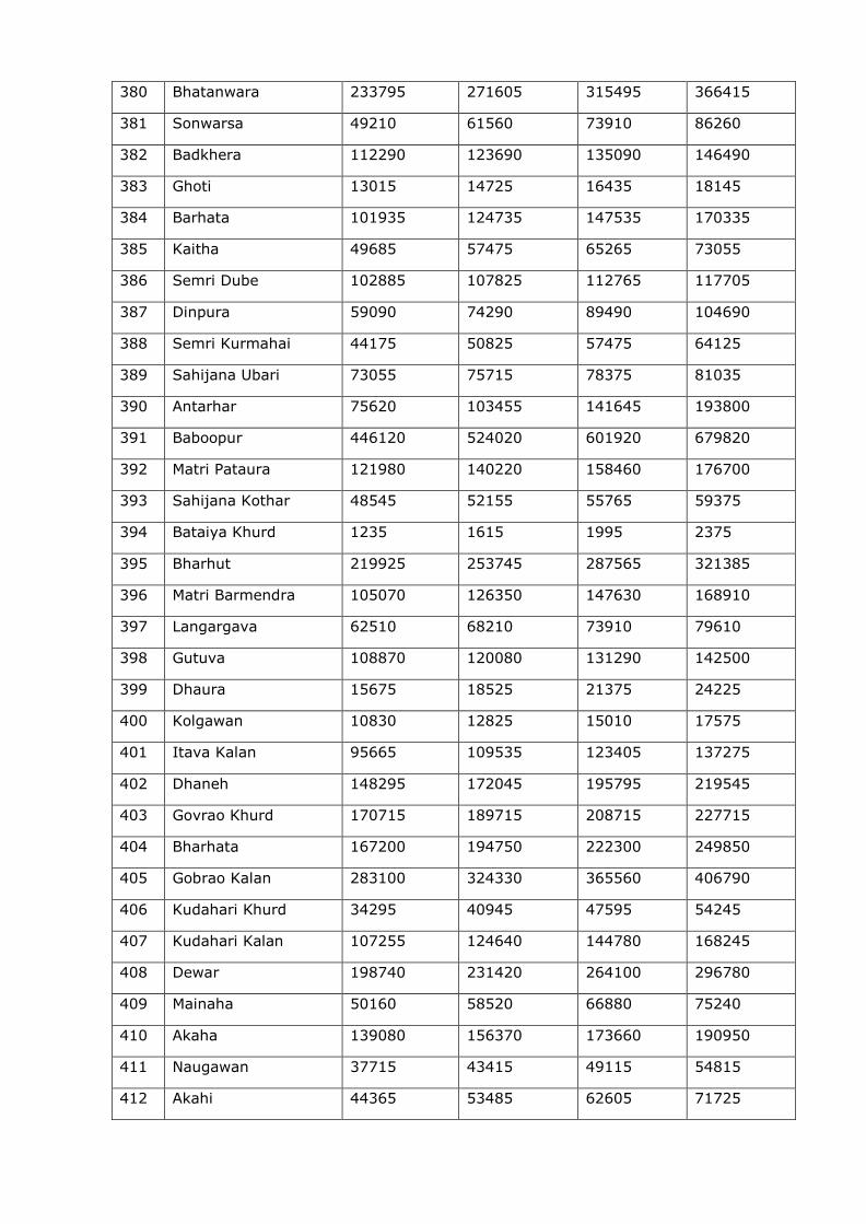
380 Bhatanwara 233795 271605 315495 366415
381 Sonwarsa 49210 61560 73910 86260
382 Badkhera 112290 123690 135090 146490
383 Ghoti 13015 14725 16435 18145
384 Barhata 101935 124735 147535 170335
385 Kaitha 49685 57475 65265 73055
386 Semri Dube 102885 107825 112765 117705
387 Dinpura 59090 74290 89490 104690
388 Semri Kurmahai 44175 50825 57475 64125
389 Sahijana Ubari 73055 75715 78375 81035
390 Antarhar 75620 103455 141645 193800
391 Baboopur 446120 524020 601920 679820
392 Matri Pataura 121980 140220 158460 176700
393 Sahijana Kothar 48545 52155 55765 59375
394 Bataiya Khurd 1235 1615 1995 2375
395 Bharhut 219925 253745 287565 321385
396 Matri Barmendra 105070 126350 147630 168910
397 Langargava 62510 68210 73910 79610
398 Gutuva 108870 120080 131290 142500
399 Dhaura 15675 18525 21375 24225
400 Kolgawan 10830 12825 15010 17575
401 Itava Kalan 95665 109535 123405 137275
402 Dhaneh 148295 172045 195795 219545
403 Govrao Khurd 170715 189715 208715 227715
404 Bharhata 167200 194750 222300 249850
405 Gobrao Kalan 283100 324330 365560 406790
406 Kudahari Khurd 34295 40945 47595 54245
407 Kudahari Kalan 107255 124640 144780 168245
408 Dewar 198740 231420 264100 296780
409 Mainaha 50160 58520 66880 75240
410 Akaha 139080 156370 173660 190950
411 Naugawan 37715 43415 49115 54815
412 Akahi 44365 53485 62605 71725
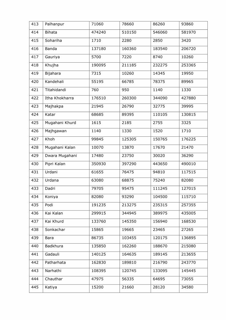
413 Palhanpur 71060 78660 86260 93860
414 Bihata 474240 510150 546060 581970
415 Sohariha 1710 2280 2850 3420
416 Banda 137180 160360 183540 206720
417 Gauriya 5700 7220 8740 10260
418 Khujha 190095 211185 232275 253365
419 Bijahara 7315 10260 14345 19950
420 Kandehali 55195 66785 78375 89965
421 Titahidandi 760 950 1140 1330
422 Itha Khokharra 176510 260300 344090 427880
423 Majhakpa 21945 26790 32775 39995
424 Katar 68685 89395 110105 130815
425 Mugahani Khurd 1615 2185 2755 3325
426 Majhgawan 1140 1330 1520 1710
427 Khoh 99845 125305 150765 176225
428 Mugahani Kalan 10070 13870 17670 21470
429 Dwara Mugahani 17480 23750 30020 36290
430 Pipri Kalan 350930 397290 443650 490010
431 Urdani 61655 76475 94810 117515
432 Urdana 63080 68875 75240 82080
433 Dadri 79705 95475 111245 127015
434 Koniya 82080 93290 104500 115710
435 Podi 191235 213275 235315 257355
436 Kai Kalan 299915 344945 389975 435005
437 Kai Khurd 133760 145350 156940 168530
438 Sonkachar 15865 19665 23465 27265
439 Bara 86735 103455 120175 136895
440 Badkhura 135850 162260 188670 215080
441 Gadauli 140125 164635 189145 213655
442 Patharhata 162830 189810 216790 243770
443 Narhathi 108395 120745 133095 145445
444 Chauthar 47975 56335 64695 73055
445 Katiya 15200 21660 28120 34580
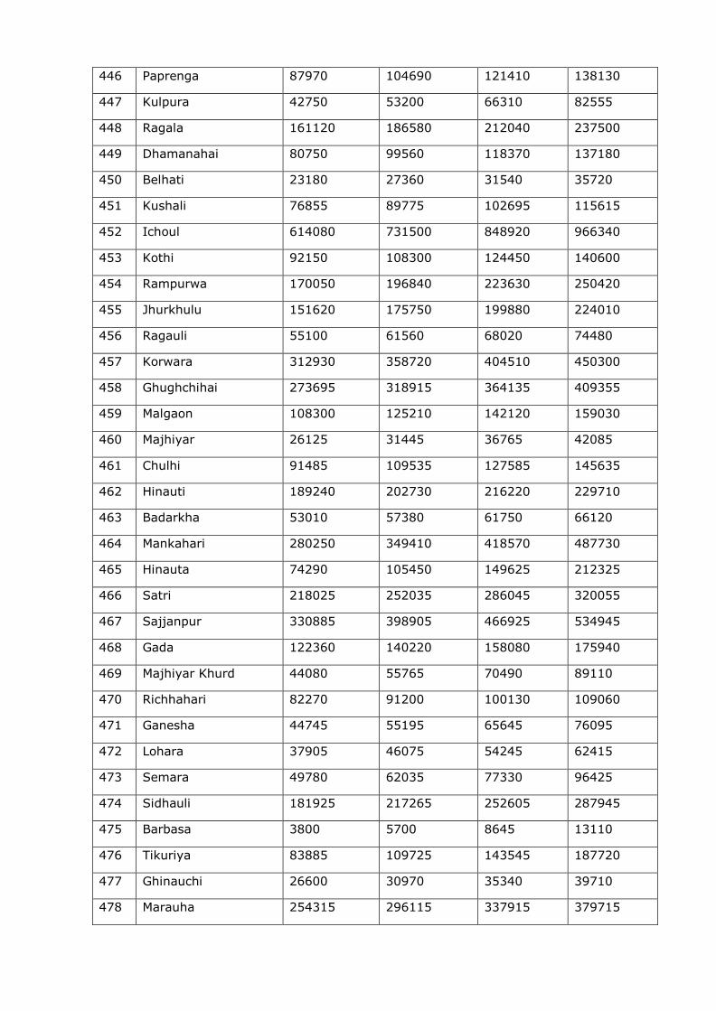
446 Paprenga 87970 104690 121410 138130
447 Kulpura 42750 53200 66310 82555
448 Ragala 161120 186580 212040 237500
449 Dhamanahai 80750 99560 118370 137180
450 Belhati 23180 27360 31540 35720
451 Kushali 76855 89775 102695 115615
452 Ichoul 614080 731500 848920 966340
453 Kothi 92150 108300 124450 140600
454 Rampurwa 170050 196840 223630 250420
455 Jhurkhulu 151620 175750 199880 224010
456 Ragauli 55100 61560 68020 74480
457 Korwara 312930 358720 404510 450300
458 Ghughchihai 273695 318915 364135 409355
459 Malgaon 108300 125210 142120 159030
460 Majhiyar 26125 31445 36765 42085
461 Chulhi 91485 109535 127585 145635
462 Hinauti 189240 202730 216220 229710
463 Badarkha 53010 57380 61750 66120
464 Mankahari 280250 349410 418570 487730
465 Hinauta 74290 105450 149625 212325
466 Satri 218025 252035 286045 320055
467 Sajjanpur 330885 398905 466925 534945
468 Gada 122360 140220 158080 175940
469 Majhiyar Khurd 44080 55765 70490 89110
470 Richhahari 82270 91200 100130 109060
471 Ganesha 44745 55195 65645 76095
472 Lohara 37905 46075 54245 62415
473 Semara 49780 62035 77330 96425
474 Sidhauli 181925 217265 252605 287945
475 Barbasa 3800 5700 8645 13110
476 Tikuriya 83885 109725 143545 187720
477 Ghinauchi 26600 30970 35340 39710
478 Marauha 254315 296115 337915 379715
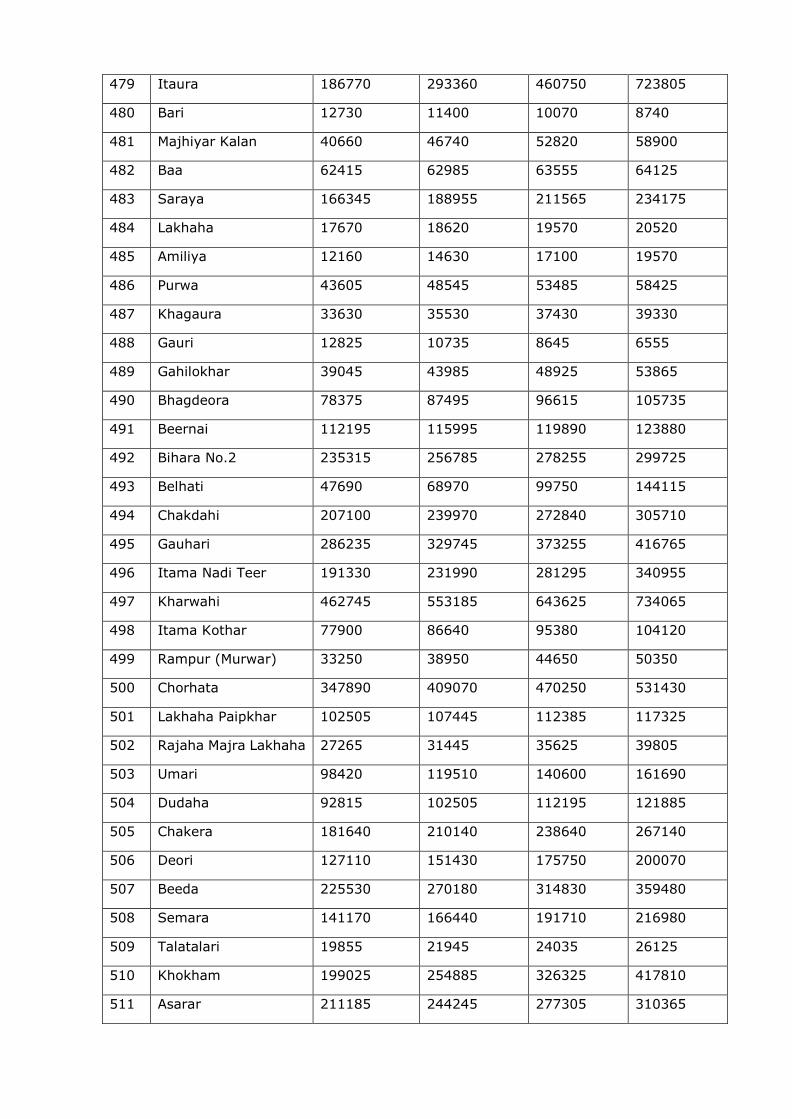
479 Itaura 186770 293360 460750 723805
480 Bari 12730 11400 10070 8740
481 Majhiyar Kalan 40660 46740 52820 58900
482 Baa 62415 62985 63555 64125
483 Saraya 166345 188955 211565 234175
484 Lakhaha 17670 18620 19570 20520
485 Amiliya 12160 14630 17100 19570
486 Purwa 43605 48545 53485 58425
487 Khagaura 33630 35530 37430 39330
488 Gauri 12825 10735 8645 6555
489 Gahilokhar 39045 43985 48925 53865
490 Bhagdeora 78375 87495 96615 105735
491 Beernai 112195 115995 119890 123880
492 Bihara No.2 235315 256785 278255 299725
493 Belhati 47690 68970 99750 144115
494 Chakdahi 207100 239970 272840 305710
495 Gauhari 286235 329745 373255 416765
496 Itama Nadi Teer 191330 231990 281295 340955
497 Kharwahi 462745 553185 643625 734065
498 Itama Kothar 77900 86640 95380 104120
499 Rampur (Murwar) 33250 38950 44650 50350
500 Chorhata 347890 409070 470250 531430
501 Lakhaha Paipkhar 102505 107445 112385 117325
502 Rajaha Majra Lakhaha 27265 31445 35625 39805
503 Umari 98420 119510 140600 161690
504 Dudaha 92815 102505 112195 121885
505 Chakera 181640 210140 238640 267140
506 Deori 127110 151430 175750 200070
507 Beeda 225530 270180 314830 359480
508 Semara 141170 166440 191710 216980
509 Talatalari 19855 21945 24035 26125
510 Khokham 199025 254885 326325 417810
511 Asarar 211185 244245 277305 310365
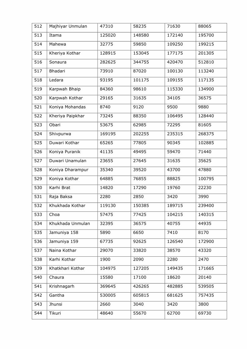
512 Majhiyar Unmulan 47310 58235 71630 88065
513 Itama 125020 148580 172140 195700
514 Mahewa 32775 59850 109250 199215
515 Kheriya Kothar 128915 153045 177175 201305
516 Sonaura 282625 344755 420470 512810
517 Bhadari 73910 87020 100130 113240
518 Ledara 93195 101175 109155 117135
519 Karpwah Bhaip 84360 98610 115330 134900
520 Karpwah Kothar 29165 31635 34105 36575
521 Koniya Mohandas 8740 9120 9500 9880
522 Kheriya Paipkhar 73245 88350 106495 128440
523 Obari 53675 62985 72295 81605
524 Shivpurwa 169195 202255 235315 268375
525 Duwari Kothar 65265 77805 90345 102885
526 Koniya Puranik 41135 49495 59470 71440
527 Duwari Unamulan 23655 27645 31635 35625
528 Koniya Dharampur 35340 39520 43700 47880
529 Koniya Kothar 64885 76855 88825 100795
530 Karhi Brat 14820 17290 19760 22230
531 Raja Baksa 2280 2850 3420 3990
532 Khukhada Kothar 119130 150385 189715 239400
533 Choa 57475 77425 104215 140315
534 Khukhada Unmulan 32395 36575 40755 44935
535 Jamuniya 158 5890 6650 7410 8170
536 Jamuniya 159 67735 92625 126540 172900
537 Naina Kothar 29070 33820 38570 43320
538 Karhi Kothar 1900 2090 2280 2470
539 Khatkhari Kothar 104975 127205 149435 171665
540 Chaura 15580 17100 18620 20140
541 Krishnagarh 369645 426265 482885 539505
542 Gantha 530005 605815 681625 757435
543 Jhunsi 2660 3040 3420 3800
544 Tikuri 48640 55670 62700 69730
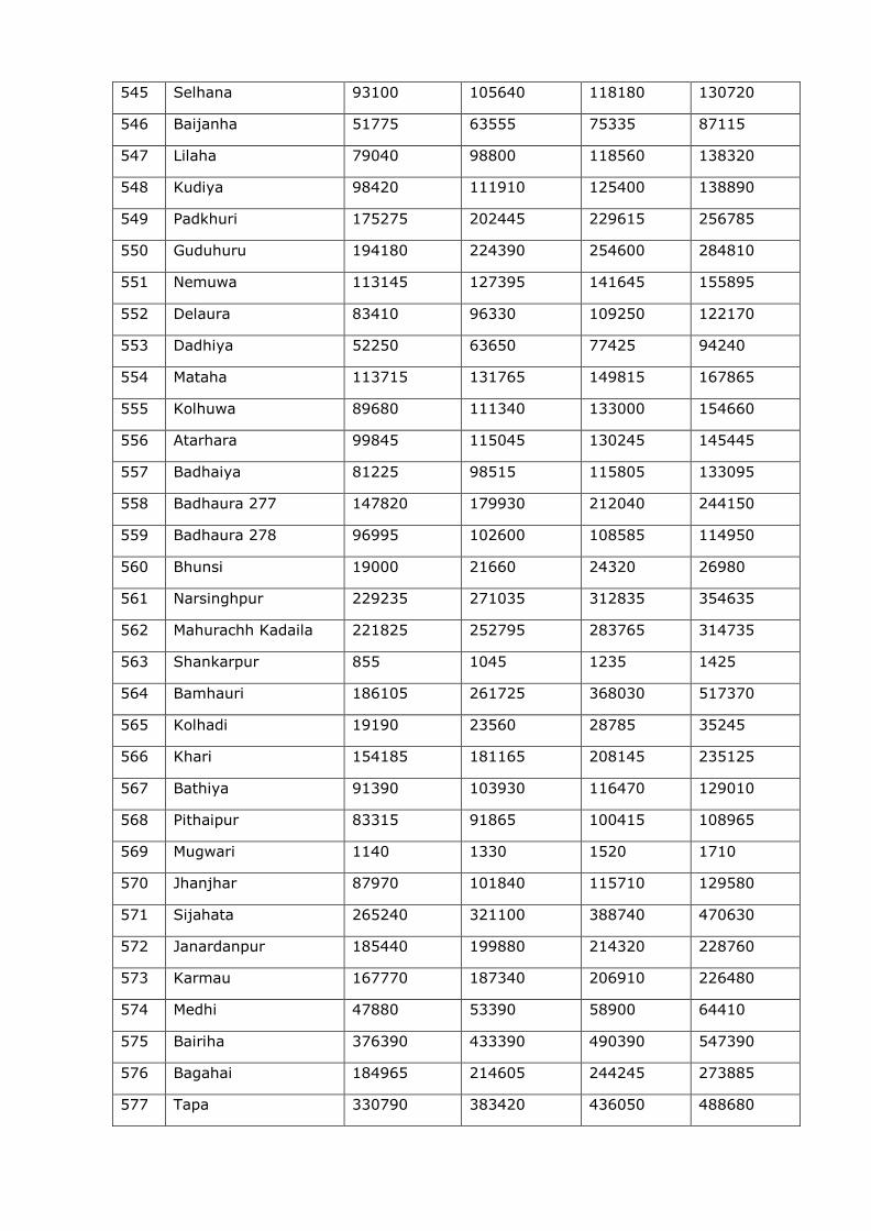
545 Selhana 93100 105640 118180 130720
546 Baijanha 51775 63555 75335 87115
547 Lilaha 79040 98800 118560 138320
548 Kudiya 98420 111910 125400 138890
549 Padkhuri 175275 202445 229615 256785
550 Guduhuru 194180 224390 254600 284810
551 Nemuwa 113145 127395 141645 155895
552 Delaura 83410 96330 109250 122170
553 Dadhiya 52250 63650 77425 94240
554 Mataha 113715 131765 149815 167865
555 Kolhuwa 89680 111340 133000 154660
556 Atarhara 99845 115045 130245 145445
557 Badhaiya 81225 98515 115805 133095
558 Badhaura 277 147820 179930 212040 244150
559 Badhaura 278 96995 102600 108585 114950
560 Bhunsi 19000 21660 24320 26980
561 Narsinghpur 229235 271035 312835 354635
562 Mahurachh Kadaila 221825 252795 283765 314735
563 Shankarpur 855 1045 1235 1425
564 Bamhauri 186105 261725 368030 517370
565 Kolhadi 19190 23560 28785 35245
566 Khari 154185 181165 208145 235125
567 Bathiya 91390 103930 116470 129010
568 Pithaipur 83315 91865 100415 108965
569 Mugwari 1140 1330 1520 1710
570 Jhanjhar 87970 101840 115710 129580
571 Sijahata 265240 321100 388740 470630
572 Janardanpur 185440 199880 214320 228760
573 Karmau 167770 187340 206910 226480
574 Medhi 47880 53390 58900 64410
575 Bairiha 376390 433390 490390 547390
576 Bagahai 184965 214605 244245 273885
577 Tapa 330790 383420 436050 488680
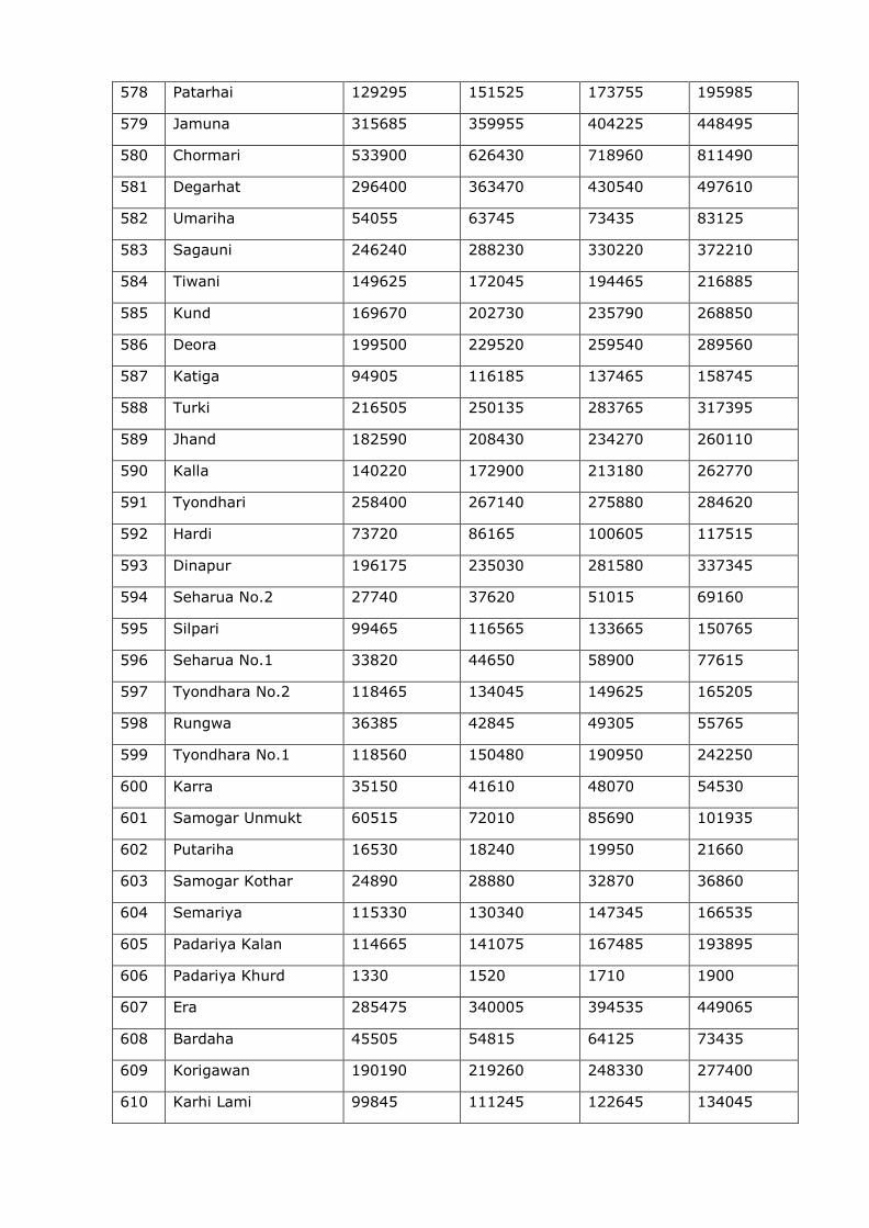
578 Patarhai 129295 151525 173755 195985
579 Jamuna 315685 359955 404225 448495
580 Chormari 533900 626430 718960 811490
581 Degarhat 296400 363470 430540 497610
582 Umariha 54055 63745 73435 83125
583 Sagauni 246240 288230 330220 372210
584 Tiwani 149625 172045 194465 216885
585 Kund 169670 202730 235790 268850
586 Deora 199500 229520 259540 289560
587 Katiga 94905 116185 137465 158745
588 Turki 216505 250135 283765 317395
589 Jhand 182590 208430 234270 260110
590 Kalla 140220 172900 213180 262770
591 Tyondhari 258400 267140 275880 284620
592 Hardi 73720 86165 100605 117515
593 Dinapur 196175 235030 281580 337345
594 Seharua No.2 27740 37620 51015 69160
595 Silpari 99465 116565 133665 150765
596 Seharua No.1 33820 44650 58900 77615
597 Tyondhara No.2 118465 134045 149625 165205
598 Rungwa 36385 42845 49305 55765
599 Tyondhara No.1 118560 150480 190950 242250
600 Karra 35150 41610 48070 54530
601 Samogar Unmukt 60515 72010 85690 101935
602 Putariha 16530 18240 19950 21660
603 Samogar Kothar 24890 28880 32870 36860
604 Semariya 115330 130340 147345 166535
605 Padariya Kalan 114665 141075 167485 193895
606 Padariya Khurd 1330 1520 1710 1900
607 Era 285475 340005 394535 449065
608 Bardaha 45505 54815 64125 73435
609 Korigawan 190190 219260 248330 277400
610 Karhi Lami 99845 111245 122645 134045
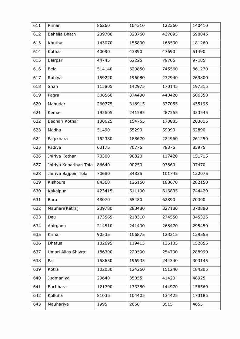
611 Rimar 86260 104310 122360 140410
612 Bahelia Bhath 239780 323760 437095 590045
613 Khutha 143070 155800 168530 181260
614 Kothar 40090 43890 47690 51490
615 Bairpar 44745 62225 79705 97185
616 Bela 514140 629850 745560 861270
617 Ruhiya 159220 196080 232940 269800
618 Shah 115805 142975 170145 197315
619 Pagra 308560 374490 440420 506350
620 Mahudar 260775 318915 377055 435195
621 Kemar 195605 241585 287565 333545
622 Badhari Kothar 130625 154755 178885 203015
623 Madha 51490 55290 59090 62890
624 Paipkhara 152380 188670 224960 261250
625 Padiya 63175 70775 78375 85975
626 Jhiriya Kothar 70300 90820 117420 151715
627 Jhiriya Koparihan Tola 86640 90250 93860 97470
628 Jhiriya Bajpein Tola 70680 84835 101745 122075
629 Kishoura 84360 126160 188670 282150
630 Kakalpur 423415 511100 616835 744420
631 Bara 48070 55480 62890 70300
632 Mauhari(Katra) 239780 283480 327180 370880
633 Deu 173565 218310 274550 345325
634 Ahirgaon 214510 241490 268470 295450
635 Kirhai 90535 106875 123215 139555
636 Dhatua 102695 119415 136135 152855
637 Umari Alias Shivraji 186390 220590 254790 288990
638 Pal 158650 196935 244340 303145
639 Kotra 102030 124260 151240 184205
640 Judmaniya 29640 35055 41420 48925
641 Bachhara 121790 133380 144970 156560
642 Kolluha 81035 104405 134425 173185
643 Mauhariya 1995 2660 3515 4655
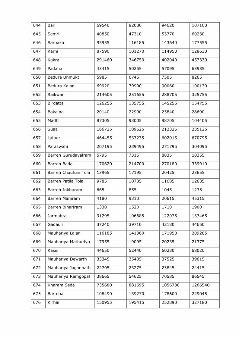
644 Bari 69540 82080 94620 107160
645 Semri 40850 47310 53770 60230
646 Sarbaka 93955 116185 143640 177555
647 Karhi 87590 101270 114950 128630
648 Kakra 291460 346750 402040 457330
649 Padaha 43415 50255 57095 63935
650 Bedura Unmukt 5985 6745 7505 8265
651 Bedura Kalan 69920 79990 90060 100130
652 Raikwar 214605 251655 288705 325755
653 Birdatta 126255 135755 145255 154755
654 Bakaina 20140 22990 25840 28690
655 Madhi 87305 93005 98705 104405
656 Suaa 166725 189525 212325 235125
657 Lalpur 464455 533235 602015 670795
658 Paraswahi 207195 239495 271795 304095
659 Barreh Gurudayalram 5795 7315 8835 10355
660 Barreh Bada 170620 214700 270180 339910
661 Barreh Chauhan Tola 13965 17195 20425 23655
662 Barreh Patila Tola 9785 10735 11685 12635
663 Barreh Jokhuram 665 855 1045 1235
664 Barreh Maniram 4180 9310 20615 45315
665 Barreh Bihariram 1330 1520 1710 1900
666 Jarmohra 91295 106685 122075 137465
667 Gadauli 37240 39710 42180 44650
668 Mauhariya Lalan 116185 141360 171950 209285
669 Mauhariya Mathuriya 17955 19095 20235 21375
670 Kasei 44650 52440 60230 68020
671 Mauhariya Dewarth 33345 35435 37525 39615
672 Mauhariya Jagannath 22705 23275 23845 24415
673 Mauhariya Ramgopal 38665 54625 70585 86545
674 Kharam Seda 735680 881695 1056780 1266540
675 Bartona 108490 139270 178600 229045
676 Kirhai 150955 195415 252890 327180
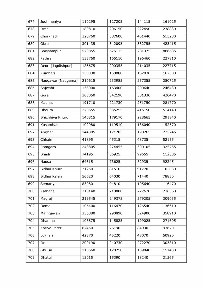
677 Judhmaniya 110295 127205 144115 161025
678 Itma 189810 206150 222490 238830
679 Chorkhadi 323760 387600 451440 515280
680 Obra 301435 342095 382755 423415
681 Bhishampur 570855 676115 781375 886635
682 Pathra 133760 165110 196460 227810
683 Deori (Jagdishpur) 186675 200355 214035 227715
684 Kumhari 153330 158080 162830 167580
685 Naugawan(Naugama) 210615 233985 257355 280725
686 Bajwahi 133000 163400 200640 246430
687 Gora 303050 342190 381330 420470
688 Mauhat 191710 221730 251750 281770
689 Dhaura 270655 335255 415150 514140
690 Bhichhiya Khurd 140315 179170 228665 291840
691 Kusamhat 102980 119510 136040 152570
692 Amjhar 144305 171285 198265 225245
693 Chhain 41895 45315 48735 52155
694 Ramgarh 248805 274455 300105 325755
695 Bhadri 74195 86925 99655 112385
696 Nausa 64315 73625 82935 92245
697 Bidhui Khurd 71250 81510 91770 102030
698 Bidhui Kalan 56620 64030 71440 78850
699 Semariya 83980 94810 105640 116470
700 Kathaha 210140 218880 227620 236360
701 Magraj 219545 249375 279205 309035
702 Doma 106400 116470 126540 136610
703 Majhgawan 256880 290890 324900 358910
704 Dhamna 106875 145825 199025 271605
705 Kariya Pater 67450 76190 84930 93670
706 Lokhari 42370 45220 48070 50920
707 Itma 209190 240730 272270 303810
708 Ghuisa 116660 128250 139840 151430
709 Dhatui 13015 15390 18240 21565
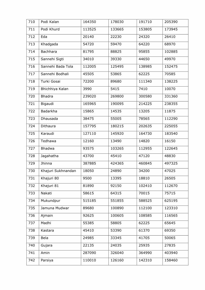
710 Podi Kalan 164350 178030 191710 205390
711 Podi Khurd 113525 133665 153805 173945
712 Eda 20140 22230 24320 26410
713 Khadgada 54720 59470 64220 68970
714 Bachhara 81795 88825 95855 102885
715 Sannehi Sigti 34010 39330 44650 49970
716 Sannehi Bada Tola 112005 125495 138985 152475
717 Sannehi Bodhali 45505 53865 62225 70585
718 Turki Gosai 72200 89680 111340 138225
719 Bhichhiya Kalan 3990 5415 7410 10070
720 Bhadra 239020 269800 300580 331360
721 Bigaudi 165965 190095 214225 238355
722 Badarkha 15865 14535 13205 11875
723 Dhausada 38475 55005 78565 112290
724 Dithaura 157795 180215 202635 225055
725 Karaudi 127110 145920 164730 183540
726 Tedhawa 12160 13490 14820 16150
727 Bhadwa 93575 103265 112955 122645
728 Jagahatha 43700 45410 47120 48830
729 Jhinna 387885 424365 460845 497325
730 Khajuri Sukhnandan 18050 24890 34200 47025
731 Khajuri 80 9500 13395 18810 26505
732 Khajuri 81 81890 92150 102410 112670
733 Nakati 58615 64315 70015 75715
734 Mukundpur 515185 551855 588525 625195
735 Jamuna Mudwar 89680 100890 112100 123310
736 Ajmain 92625 100605 108585 116565
737 Madhi 55385 58805 62225 65645
738 Kastara 45410 53390 61370 69350
739 Bela 24985 33345 41705 50065
740 Gujara 22135 24035 25935 27835
741 Amin 287090 326040 364990 403940
742 Parsiya 110010 126160 142310 158460
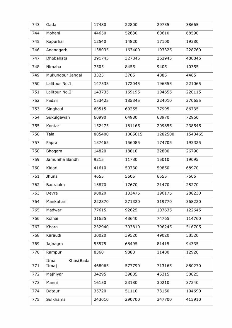
743 Gada 17480 22800 29735 38665
744 Mohani 44650 52630 60610 68590
745 Kapurhai 12540 14820 17100 19380
746 Anandgarh 138035 163400 193325 228760
747 Dhobahata 291745 327845 363945 400045
748 Nimaha 7505 8455 9405 10355
749 Mukundpur Jangal 3325 3705 4085 4465
750 Lalitpur No.1 147535 172045 196555 221065
751 Lalitpur No.2 143735 169195 194655 220115
752 Padari 153425 185345 224010 270655
753 Singhaul 60515 69255 77995 86735
754 Sukulgawan 60990 64980 68970 72960
755 Kontar 152475 181165 209855 238545
756 Tala 885400 1065615 1282500 1543465
757 Papra 137465 156085 174705 193325
758 Bhogam 14820 18810 22800 26790
759 Jamuniha Bandh 9215 11780 15010 19095
760 Kidari 41610 50730 59850 68970
761 Jhunsi 4655 5605 6555 7505
762 Badraukh 13870 17670 21470 25270
763 Devra 90820 133475 196175 288230
764 Mankahari 222870 271320 319770 368220
765 Madwar 77615 92625 107635 122645
766 Kolhai 31635 48640 74765 114760
767 Khara 232940 303810 396245 516705
768 Karaudi 30020 39520 49020 58520
769 Jajnagra 55575 68495 81415 94335
770 Rampur 8360 9880 11400 12920
771
Itma Khas(Bada
Itma) 468065 577790 713165 880270
772 Majhiyar 34295 39805 45315 50825
773 Manni 16150 23180 30210 37240
774 Dataur 35720 51110 73150 104690
775 Sulkhama 243010 290700 347700 415910
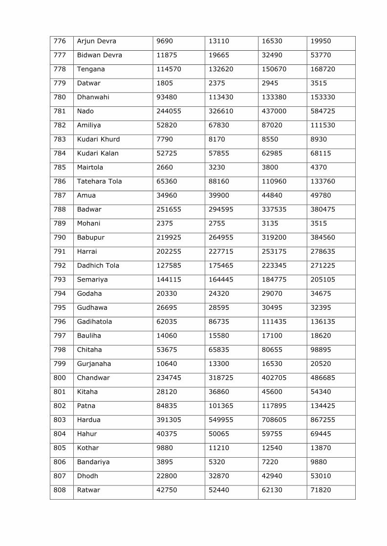
776 Arjun Devra 9690 13110 16530 19950
777 Bidwan Devra 11875 19665 32490 53770
778 Tengana 114570 132620 150670 168720
779 Datwar 1805 2375 2945 3515
780 Dhanwahi 93480 113430 133380 153330
781 Nado 244055 326610 437000 584725
782 Amiliya 52820 67830 87020 111530
783 Kudari Khurd 7790 8170 8550 8930
784 Kudari Kalan 52725 57855 62985 68115
785 Mairtola 2660 3230 3800 4370
786 Tatehara Tola 65360 88160 110960 133760
787 Amua 34960 39900 44840 49780
788 Badwar 251655 294595 337535 380475
789 Mohani 2375 2755 3135 3515
790 Babupur 219925 264955 319200 384560
791 Harrai 202255 227715 253175 278635
792 Dadhich Tola 127585 175465 223345 271225
793 Semariya 144115 164445 184775 205105
794 Godaha 20330 24320 29070 34675
795 Gudhawa 26695 28595 30495 32395
796 Gadihatola 62035 86735 111435 136135
797 Bauliha 14060 15580 17100 18620
798 Chitaha 53675 65835 80655 98895
799 Gurjanaha 10640 13300 16530 20520
800 Chandwar 234745 318725 402705 486685
801 Kitaha 28120 36860 45600 54340
802 Patna 84835 101365 117895 134425
803 Hardua 391305 549955 708605 867255
804 Hahur 40375 50065 59755 69445
805 Kothar 9880 11210 12540 13870
806 Bandariya 3895 5320 7220 9880
807 Dhodh 22800 32870 42940 53010
808 Ratwar 42750 52440 62130 71820
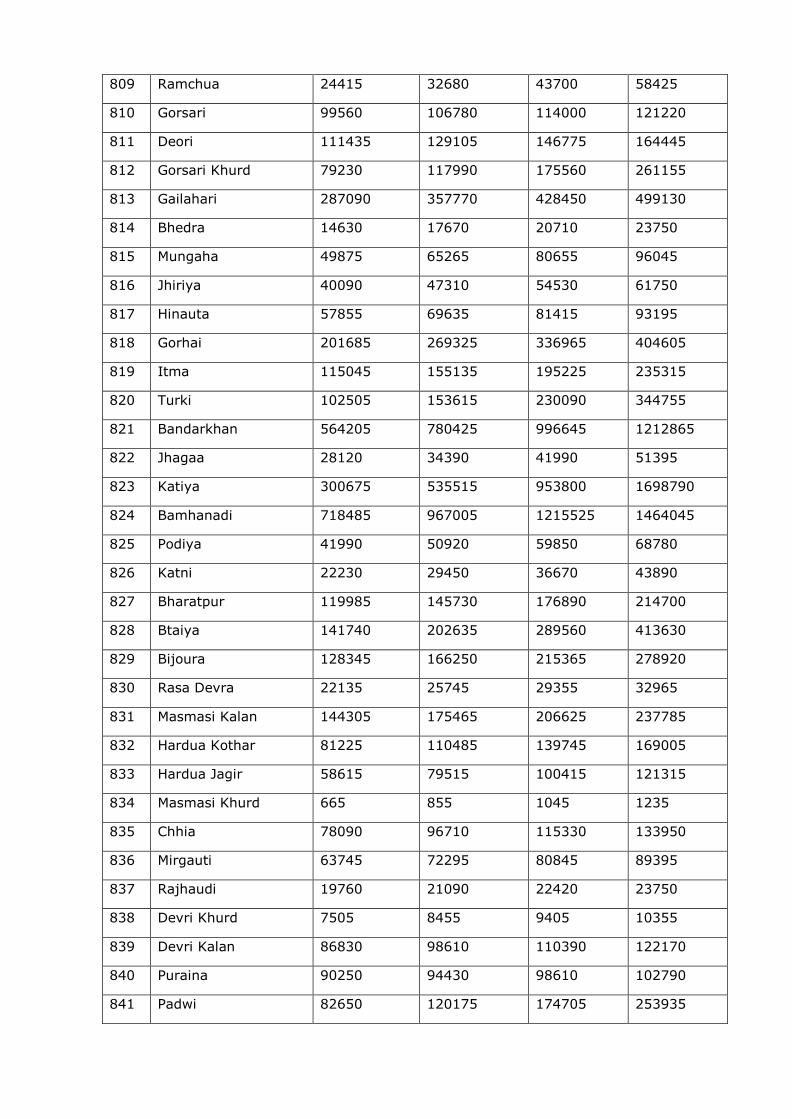
809 Ramchua 24415 32680 43700 58425
810 Gorsari 99560 106780 114000 121220
811 Deori 111435 129105 146775 164445
812 Gorsari Khurd 79230 117990 175560 261155
813 Gailahari 287090 357770 428450 499130
814 Bhedra 14630 17670 20710 23750
815 Mungaha 49875 65265 80655 96045
816 Jhiriya 40090 47310 54530 61750
817 Hinauta 57855 69635 81415 93195
818 Gorhai 201685 269325 336965 404605
819 Itma 115045 155135 195225 235315
820 Turki 102505 153615 230090 344755
821 Bandarkhan 564205 780425 996645 1212865
822 Jhagaa 28120 34390 41990 51395
823 Katiya 300675 535515 953800 1698790
824 Bamhanadi 718485 967005 1215525 1464045
825 Podiya 41990 50920 59850 68780
826 Katni 22230 29450 36670 43890
827 Bharatpur 119985 145730 176890 214700
828 Btaiya 141740 202635 289560 413630
829 Bijoura 128345 166250 215365 278920
830 Rasa Devra 22135 25745 29355 32965
831 Masmasi Kalan 144305 175465 206625 237785
832 Hardua Kothar 81225 110485 139745 169005
833 Hardua Jagir 58615 79515 100415 121315
834 Masmasi Khurd 665 855 1045 1235
835 Chhia 78090 96710 115330 133950
836 Mirgauti 63745 72295 80845 89395
837 Rajhaudi 19760 21090 22420 23750
838 Devri Khurd 7505 8455 9405 10355
839 Devri Kalan 86830 98610 110390 122170
840 Puraina 90250 94430 98610 102790
841 Padwi 82650 120175 174705 253935
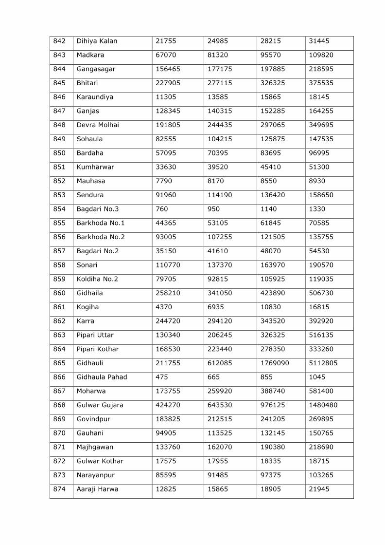
842 Dihiya Kalan 21755 24985 28215 31445
843 Madkara 67070 81320 95570 109820
844 Gangasagar 156465 177175 197885 218595
845 Bhitari 227905 277115 326325 375535
846 Karaundiya 11305 13585 15865 18145
847 Ganjas 128345 140315 152285 164255
848 Devra Molhai 191805 244435 297065 349695
849 Sohaula 82555 104215 125875 147535
850 Bardaha 57095 70395 83695 96995
851 Kumharwar 33630 39520 45410 51300
852 Mauhasa 7790 8170 8550 8930
853 Sendura 91960 114190 136420 158650
854 Bagdari No.3 760 950 1140 1330
855 Barkhoda No.1 44365 53105 61845 70585
856 Barkhoda No.2 93005 107255 121505 135755
857 Bagdari No.2 35150 41610 48070 54530
858 Sonari 110770 137370 163970 190570
859 Koldiha No.2 79705 92815 105925 119035
860 Gidhaila 258210 341050 423890 506730
861 Kogiha 4370 6935 10830 16815
862 Karra 244720 294120 343520 392920
863 Pipari Uttar 130340 206245 326325 516135
864 Pipari Kothar 168530 223440 278350 333260
865 Gidhauli 211755 612085 1769090 5112805
866 Gidhaula Pahad 475 665 855 1045
867 Moharwa 173755 259920 388740 581400
868 Gulwar Gujara 424270 643530 976125 1480480
869 Govindpur 183825 212515 241205 269895
870 Gauhani 94905 113525 132145 150765
871 Majhgawan 133760 162070 190380 218690
872 Gulwar Kothar 17575 17955 18335 18715
873 Narayanpur 85595 91485 97375 103265
874 Aaraji Harwa 12825 15865 18905 21945
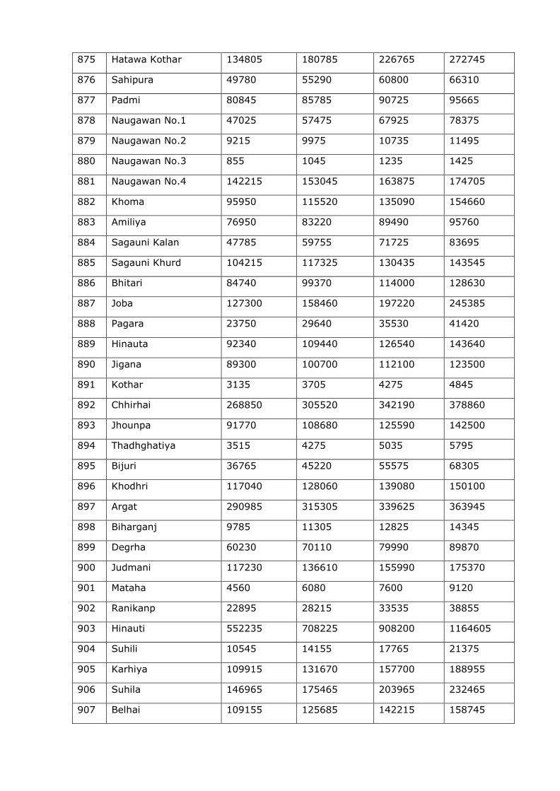
875 Hatawa Kothar 134805 180785 226765 272745
876 Sahipura 49780 55290 60800 66310
877 Padmi 80845 85785 90725 95665
878 Naugawan No.1 47025 57475 67925 78375
879 Naugawan No.2 9215 9975 10735 11495
880 Naugawan No.3 855 1045 1235 1425
881 Naugawan No.4 142215 153045 163875 174705
882 Khoma 95950 115520 135090 154660
883 Amiliya 76950 83220 89490 95760
884 Sagauni Kalan 47785 59755 71725 83695
885 Sagauni Khurd 104215 117325 130435 143545
886 Bhitari 84740 99370 114000 128630
887 Joba 127300 158460 197220 245385
888 Pagara 23750 29640 35530 41420
889 Hinauta 92340 109440 126540 143640
890 Jigana 89300 100700 112100 123500
891 Kothar 3135 3705 4275 4845
892 Chhirhai 268850 305520 342190 378860
893 Jhounpa 91770 108680 125590 142500
894 Thadhghatiya 3515 4275 5035 5795
895 Bijuri 36765 45220 55575 68305
896 Khodhri 117040 128060 139080 150100
897 Argat 290985 315305 339625 363945
898 Biharganj 9785 11305 12825 14345
899 Degrha 60230 70110 79990 89870
900 Judmani 117230 136610 155990 175370
901 Mataha 4560 6080 7600 9120
902 Ranikanp 22895 28215 33535 38855
903 Hinauti 552235 708225 908200 1164605
904 Suhili 10545 14155 17765 21375
905 Karhiya 109915 131670 157700 188955
906 Suhila 146965 175465 203965 232465
907 Belhai 109155 125685 142215 158745
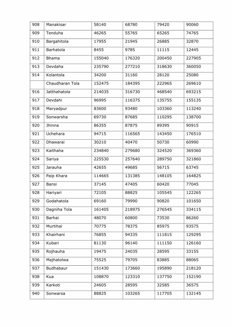
908 Manakisar 58140 68780 79420 90060
909 Tenduha 46265 55765 65265 74765
910 Bargahitola 17955 21945 26885 32870
911 Barhatola 8455 9785 11115 12445
912 Bhama 155040 176320 200450 227905
913 Devdaha 235790 277210 318630 360050
914 Kolantola 34200 31160 28120 25080
Chaudharan Tola 152475 184395 222965 269610
916 Jatthahatola 214035 316730 468540 693215
917 Devdahi 96995 116375 135755 155135
918 Maryadpur 83600 93480 103360 113240
919 Sonwarsha 69730 87685 110295 138700
920 Jhinna 86355 87875 89395 90915
921 Uchehara 94715 116565 143450 176510
922 Dhawarai 30210 40470 50730 60990
923 Kaithaha 234840 279680 324520 369360
924 Sariya 225530 257640 289750 321860
925 Jarauha 42655 49685 56715 63745
926 Paip Khara 114665 131385 148105 164825
927 Bansi 37145 47405 60420 77045
928 Hariyari 72105 88825 105545 122265
929 Godahatola 69160 79990 90820 101650
930 Dagniha Tola 161405 218975 276545 334115
931 Barhai 48070 60800 73530 86260
932 Murtihai 70775 78375 85975 93575
933 Khairhani 76855 94335 111815 129295
934 Kubari 81130 96140 111150 126160
935 Rojhauha 19475 24035 28595 33155
936 Majhatolwa 75525 79705 83885 88065
937 Budhabaur 151430 173660 195890 218120
938 Kua 108870 123310 137750 152190
939 Karkoti 24605 28595 32585 36575
940 Sonwarsa 88825 103265 117705 132145
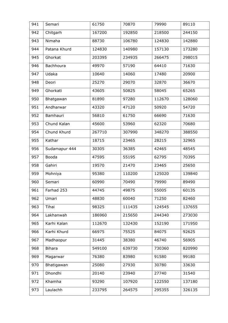
941 Semari 61750 70870 79990 89110
942 Chitgarh 167200 192850 218500 244150
943 Nimaha 88730 106780 124830 142880
944 Patana Khurd 124830 140980 157130 173280
945 Ghorkat 203395 234935 266475 298015
946 Bachhoura 49970 57190 64410 71630
947 Udaka 10640 14060 17480 20900
948 Deori 25270 29070 32870 36670
949 Ghorkati 43605 50825 58045 65265
950 Bhatgawan 81890 97280 112670 128060
951 Andharwar 43320 47120 50920 54720
952 Bamhauri 56810 61750 66690 71630
953 Chund Kalan 45600 53960 62320 70680
954 Chund Khurd 267710 307990 348270 388550
955 Kathar 18715 23465 28215 32965
956 Sudamapur 444 30305 36385 42465 48545
957 Booda 47595 55195 62795 70395
958 Gahiri 19570 21470 23465 25650
959 Mohniya 95380 110200 125020 139840
960 Semari 60990 70490 79990 89490
961 Farhad 253 44745 49875 55005 60135
962 Umari 48830 60040 71250 82460
963 Tihai 98325 111435 124545 137655
964 Lakhanwah 186960 215650 244340 273030
965 Karhi Kalan 112670 132430 152190 171950
966 Karhi Khurd 66975 75525 84075 92625
967 Madhaopur 31445 38380 46740 56905
968 Bihara 549100 639730 730360 820990
969 Magarwar 76380 83980 91580 99180
970 Bhatigawan 25080 27930 30780 33630
971 Dhondhi 20140 23940 27740 31540
972 Khamha 93290 107920 122550 137180
973 Laulachh 233795 264575 295355 326135
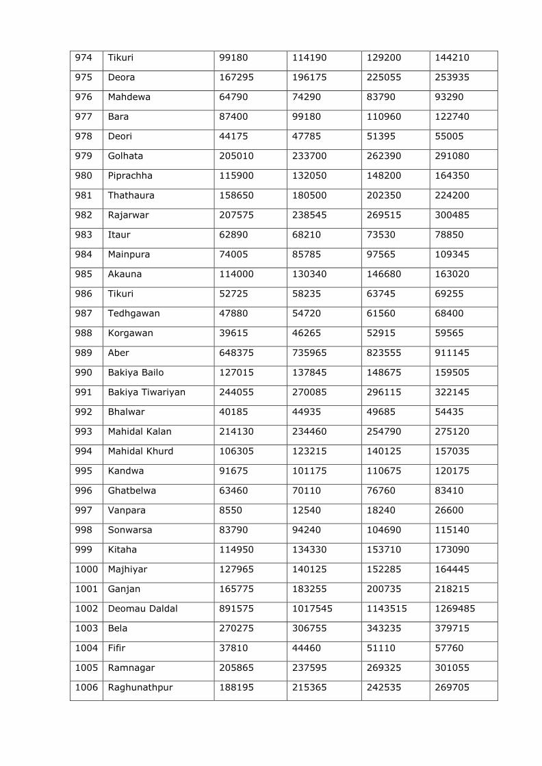
974 Tikuri 99180 114190 129200 144210
975 Deora 167295 196175 225055 253935
976 Mahdewa 64790 74290 83790 93290
977 Bara 87400 99180 110960 122740
978 Deori 44175 47785 51395 55005
979 Golhata 205010 233700 262390 291080
980 Piprachha 115900 132050 148200 164350
981 Thathaura 158650 180500 202350 224200
982 Rajarwar 207575 238545 269515 300485
983 Itaur 62890 68210 73530 78850
984 Mainpura 74005 85785 97565 109345
985 Akauna 114000 130340 146680 163020
986 Tikuri 52725 58235 63745 69255
987 Tedhgawan 47880 54720 61560 68400
988 Korgawan 39615 46265 52915 59565
989 Aber 648375 735965 823555 911145
990 Bakiya Bailo 127015 137845 148675 159505
991 Bakiya Tiwariyan 244055 270085 296115 322145
992 Bhalwar 40185 44935 49685 54435
993 Mahidal Kalan 214130 234460 254790 275120
994 Mahidal Khurd 106305 123215 140125 157035
995 Kandwa 91675 101175 110675 120175
996 Ghatbelwa 63460 70110 76760 83410
997 Vanpara 8550 12540 18240 26600
998 Sonwarsa 83790 94240 104690 115140
999 Kitaha 114950 134330 153710 173090
1000 Majhiyar 127965 140125 152285 164445
1001 Ganjan 165775 183255 200735 218215
1002 Deomau Daldal 891575 1017545 1143515 1269485
1003 Bela 270275 306755 343235 379715
1004 Fifir 37810 44460 51110 57760
1005 Ramnagar 205865 237595 269325 301055
1006 Raghunathpur 188195 215365 242535 269705
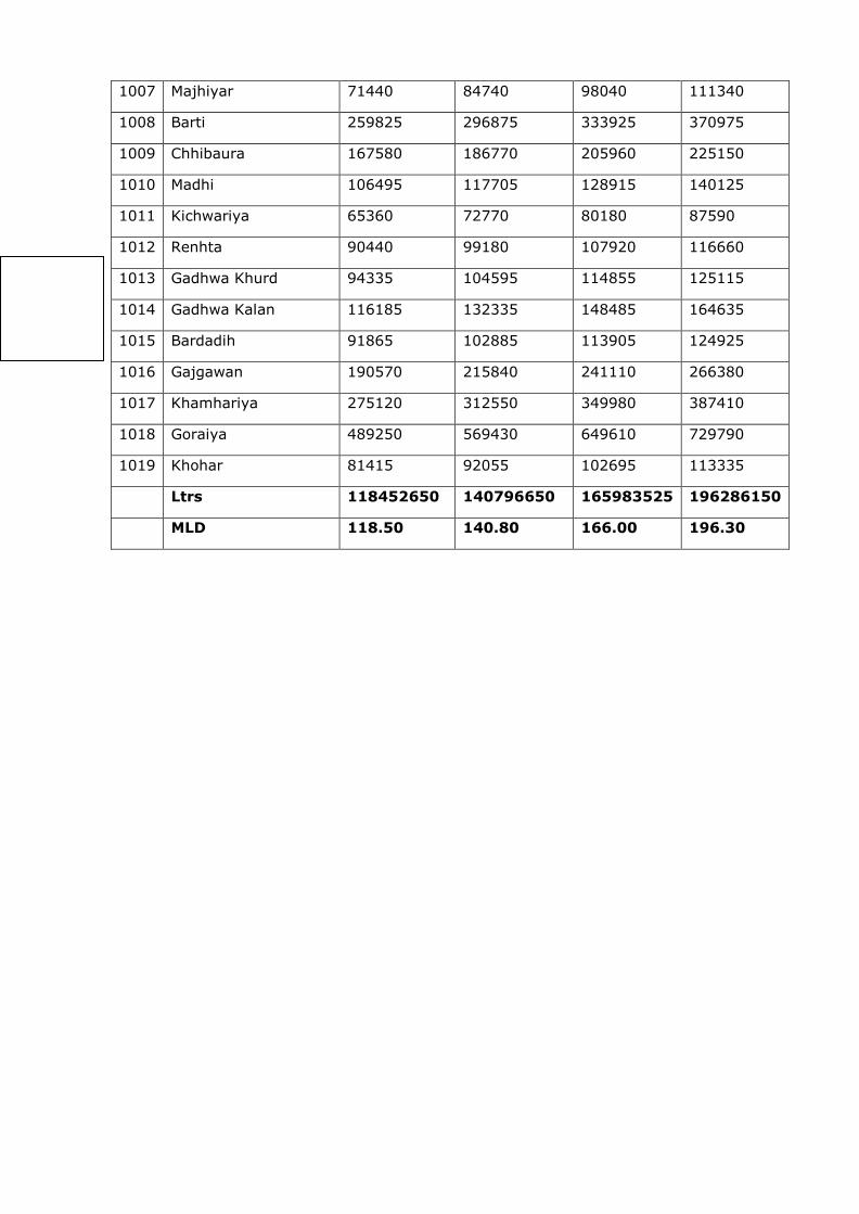
1007 Majhiyar 71440 84740 98040 111340
1008 Barti 259825 296875 333925 370975
1009 Chhibaura 167580 186770 205960 225150
1010 Madhi 106495 117705 128915 140125
1011 Kichwariya 65360 72770 80180 87590
1012 Renhta 90440 99180 107920 116660
1013 Gadhwa Khurd 94335 104595 114855 125115
1014 Gadhwa Kalan 116185 132335 148485 164635
1015 Bardadih 91865 102885 113905 124925
1016 Gajgawan 190570 215840 241110 266380
1017 Khamhariya 275120 312550 349980 387410
1018 Goraiya 489250 569430 649610 729790
1019 Khohar 81415 92055 102695 113335
Ltrs 118452650 140796650 165983525 196286150
MLD 118.50 140.80 166.00 196.30