macroscopic simulation and experimental …...macroscopic simulation and experimental measurement of...
TRANSCRIPT

Int J Adv Manuf Technol (2017) 88:1309–1317DOI 10.1007/s00170-016-8819-6
ORIGINAL ARTICLE
Macroscopic simulation and experimental measurementof melt pool characteristics in selective electron beammelting of Ti-6Al-4V
Daniel Riedlbauer1 ·Thorsten Scharowsky2 ·Robert F. Singer2 · Paul Steinmann1 ·Carolin Korner2 · Julia Mergheim1
Received: 28 August 2015 / Accepted: 22 April 2016 / Published online: 12 May 2016© The Author(s) 2016. This article is published with open access at Springerlink.com
Abstract Selective electron beam melting of Ti-6Al-4Vis a promising additive manufacturing process to producecomplex parts layer-by-layer additively. The quality anddimensional accuracy of the produced parts depend on vari-ous process parameters and their interactions. In the presentcontribution, the lifetime, width and depth of the pools ofmolten powder material are analyzed for different beampowers, scan speeds and line energies in experiments andsimulations. In the experiments, thin-walled structures arebuilt with an ARCAM AB A2 selective electron beam melt-ing machine and for the simulations a thermal finite elementsimulation tool is used, which is developed by the authors tosimulate the temperature distribution in the selective elec-tron beam melting process. The experimental and numericalresults are compared and a good agreement is observed. Thelifetime of the melt pool increases linearly with the lineenergy, whereby the melt pool dimensions show a nonlinearrelation with the line energy.
Keywords Additive manufacturing · Selective electronbeam melting · Ti-6Al-4V · Heat transfer simulation · Meltpool characteristics
� Daniel [email protected]
1 Chair of Applied Mechanics, Friedrich-Alexander-UniversitatErlangen-Nurnberg, Egerlandstraße 5, 91058 Erlangen,Germany
2 Chair of Metals Science and Technology,Friedrich-Alexander-Universitat Erlangen-Nurnberg,Martensstraße 5, 91058 Erlangen, Germany
1 Introduction
The titanium aluminium vanadium alloy Ti-6Al-4V is acommonly used engineering material in the automotive,aerospace and medical industry [20], well suited for lightweight construction due to its low density and goodmechan-ical properties. In the last few years, Ti-6Al-4V also becamemore important for the additive manufacturing of geometri-cally complex parts by the selective electron beam meltingprocess (SEBM) [17]. The SEBM process is just one amongmany additive manufacturing processes [6] and is subjectto extensive research to exploit the potentials of the elec-tron beam, such as extremely high scan speeds and the highenergy density. Major issues are the power consumption andefficiency of the electron beam [5], the evaporation of alloy-ing elements [19], the choice of suited process parameters[19] and the search for new materials [10, 13–15, 26, 28,29].
In the SEBM process of metal powders, the size andlifetime of the melt pool have a significant influence onthe dimensional accuracy of the produced part [1], espe-cially for thin-walled structures [25]. However, due to theextremely high temperatures of several thousand Kelvinand experimental challenges as X-rays, vacuum and met-allization, the measurement of temperatures and melt poolcharacteristics is very difficult during the SEBM process.Therefore, it is helpful to model and simulate the SEBMprocess to investigate the evolution of temperatures andthe dimensions and lifetime of the melt pool. The insightsgained from the simulations can be used to further improvethe predictability of the melting process and to optimize theparameters of the SEBM process, e.g. beam power and scanspeed.
For the simulation of the SEBM process, various mod-elling approaches exist. In [2, 23, 24], the Lattice - Boltzman

1310 Int J Adv Manuf Technol (2017) 88:1309–1317
- Method (LBM) is used to simulate the temperature in aTi-6Al-4V powder bed on a mesoscopic scale resolving par-ticular powder particles. However, the simulation of singlepowder particles on small time and length scales is compu-tationally intensive and thus not suited for the simulation ofthe complete SEBM process. For this purpose, the finite ele-ment method (FEM) seems to be more appropriate since itconsiders the powder material as a continuum. This methodis applied in [11, 18, 30] to simulate the mechanical stressesand warpage of the re-solidified Ti-6Al-4V material in theSEBM process. The simulation of the temperature distribu-tion with FEM in the SEBM process is conducted in [32, 33]to analyze the preheating of the metallic powder materialand to study the impact of scan speed and beam power onthe temperature distribution and the part quality. In [9], thetemperature distribution in the SEBM process is simulatedwith FEM and the influence of different scan strategies onthe homogeneity of the temperature distribution is analyzed.
In the present contribution, the temperature distributionin the SEBM of Ti-6Al-4V is simulated with FEM for dif-ferent scan parameters to investigate the melt pool width,depth and life time. Analogous experiments are performedand the experimental and numerical results are compared.
2 Experimental setup
2.1 Selective electron beam melting process
The SEBM process is a powder bed-based additive man-ufacturing process using an electron beam as heat sourcefor melting metal powders. The process takes place in avacuum chamber to achieve a high quality electron beamand to guarantee protection of powder material from theatmosphere.
For this contribution, experimental work is done using anARCAM AB A2 machine, which is schematically shown inFig. 1. A high speed camera Photron Fastcam SA3 with anInfinity K2 DistaMax Long-Distance Microscope objectiveand a Cavitar Cavilux HF laser with a wavelength of 810 nm± 10 nm for illumination are installed on top of the vacuumchamber for process observation.
The building process starts with preheating the steel startplate to the building temperature of 730 ◦C. Afterwards, thefour steps of the build process are repeated until completionof the parts. The four-process steps are powder applicationby a rake, preheating of the applied layer, selective meltingaccording to part geometry and lowering of the build table.During the process, a small helium pressure of 2.0 × 10⁻⁶
bar is maintained in the vacuum chamber to increase the sta-bility of the process. After finalizing the build process, thepowder is removed from the parts by shot peening with thesame powder which is used for the process. Nearly 100 %
buildtable
rake start plate
electron beam gun
high speed camera
objective
laser
band pass filter
mirror system
powder
vacuum chamber
90° side view
powderhopper
lead glass
laser
objective
optical path
optical path
laser light
laser light
electronbeamgun
Fig. 1 Schematic view of the electron beam melting equipment
of the powder is reused for the next build process [16]. Inthe present research, an Ti-6Al-4V powder with a compo-sition following DIN 17851 and a mean particle diameterd0,50 of 69 μm is used. The powder exhibits a particle sizedistribution between a minimum particle size of 33 μm anda maximum size of 118 μm.
For each layer, the build platform is lowered by thenominal layer thickness dnominal equal to 50 μm.
Remark 1 Due to the consolidation of the powder, theeffective powder layer thickness deffective is larger than 50μm and depends on the experimentally determined relativepowder density ρrel = 58.3 % as
deffective = dnominal
ρrel= 50 μm
0.583= 86 μm . (1)
Since the consolidation of the powder is not modelled a con-stant effective powder layer thickness deffective of 86 μm isassumed in the simulations.
In the experiments, the electron beam describes a singlestraight line in each layer resulting in a wall after severallayers. Two building processes are performed and for eachparameter combination in Table 1 a wall with a height of 3mm and thus 60 powder layers is built. A parameter com-bination is investigated by varying the electron beam powerPb, the scan speed vb and the energy input or line energy El,which is defined as
El := Pb/vb . (2)
The parameter combinations in Table 1 are chosen sincethe quality of the so produced parts is sufficiently high.

Int J Adv Manuf Technol (2017) 88:1309–1317 1311
Table 1 Parameter combinations for experiments
Pb [W] vb [ms ] El [ Jmm ]
160 1.6 0.1
240 0.8 0.3
320 1.6 0.2
480 1.6 0.3
640 1.6 0.4
720 2.4 0.3
800 4.0 0.2
1120 5.6 0.2
1600 8.0 0.2
3 Simulation
3.1 Thermal model
For the simulation of the dimensions and lifetime of the meltpool, the temperature distribution during the SEBM processfor Ti-6Al-4V is required. It is simulated from a macro-scopic point of view, i.e. the powder material is not modelledas single particles, but as a continuum with homogenizedmaterial properties. The same approach of a continuumbody is used for the molten and the re-solidified material. Inorder to compute the unknown temperature ϑ , the transientheat transfer equation
ϑρ(ϑ)c(ϑ) = −divq + f (3)
is solved. The quantity ϑ represents the derivative of ϑ withrespect to time t . The density ρ and the heat capacity c arefunctions of the temperature ϑ and make (3) highly nonlin-ear. Equation (3) describes how the temperature changes dueto heat fluxes q and heat sources f and captures heat trans-fer by conduction, convection and radiation. In the buildingchamber in the SEBM process, high vacuum is assumed andtherefore heat convection is neglected. The heat flux gener-ated by heat conduction qc is characterized by Fourier’s law
qc = −K(ϑ) · ∇ϑ . (4)
Isotropic material behaviour is assumed and the temperaturedependent conductivity tensor K is described by
K(ϑ) = K(ϑ) I . (5)
The heat flux qr induced by radiation is captured by
qr = ε σ[ϑ4 − ϑ0
4]n . (6)
with the environment temperature ϑ0. The quantity σ is theStefan-Boltzmann constant, ε is the emissivity of the mate-rial and n is the normal vector on the surface of the radiatingmaterial. The power input of the electron beam is taken into
account by the volumetric heat source term f in equation(3). Similar to the electron beam in the real process, the heatsource f moves along the surface of the currently processedpowder layer to melt the powder material. The distributionof f is modelled by the electron beam model developedin [22]. The basis of the electron beam model is a setof semi-empirical equations and theoretical considerations.Absorption, penetration depth, electron backscattering andtransmission are incorporated in the model, which is appliedin [22] for Lattice Boltzmann simulations of the temperaturedistribution in the SEBM process and is validated againstexperiments in [22]. In order to solve (3), appropriate initialand boundary conditions for the unknown temperature haveto be added. The different phases of Ti-6Al-4V in the SEBMprocess are considered in the thermal model by temperatureand phase-dependent material parameters.
3.2 Discretisation and implementation of the thermalmodel
In order to numerically solve the heat transfer (3) for theunknown temperature ϑ , it has to be discretized in time andspace. For the discretization, the method of Rothe is adoptedand thus (3) is discretized first in time and then in space.The temporal discretization is performed with an implicitRunge-Kutta method [12]. For the spatial discretization ofEq. 3, an adaptive FE method with a very fine FE mesh inthe vicinity of the electron beam is used to capture extremetemperature gradients in the vicinity of the electron beam.In contrast, the mesh in the remaining simulation space is ascoarse as possible to minimize computing time. The meshrefinement in the beam vicinity is exemplarily shown inFig. 8. In the simulation, the position of the electron beamis known at any time step and, therefore, the mesh can berefined in these areas without the use of error estimators.The discretized version of Eq. 3 is implemented with thefinite element library deal.II [4]. The library is focussedon the efficient numerical solution of partial differentialequations with a large number of degrees of freedom.
3.3 Material parameters and setup
In agreement with the experiments, Ti-6Al-4V metal pow-der is used for the simulations. The different phases ofTi-6Al-4V are considered in the thermal model by thephase and temperature dependency of the material param-eters. The melting and solidification temperatures θm andθs are 1674 and 1615 ◦C, respectively [8]. The density ρ isassumed to be different for each material phase, but constantin temperature, compare Table 2 [3, 27].
The heat capacity c is prescribed as a nonlinear functionof temperature ϑ and is shown in Fig. 2, left. Its peak in theregion of θm represents the effect of latent heat [7, 21].

1312 Int J Adv Manuf Technol (2017) 88:1309–1317
Table 2 Density ρ of the different material phases for the simulationof the SEBM process for Ti-6Al-4V
Material phase ρ [kg/m3]
Powder 2564
Melt 3800
Solid 4420
The temperature dependency of the heat conductivity K
is illustrated in Fig. 2, right. For all phases, the conductivityK increases linearly in temperature [7].
Similar as in the experiments, the electron beamdescribes a straight path on top of the current powder layerfor different combinations of Pb and vb (Table 3). In thesimulations, more parameter combinations are investigatedthan in the experiments. The additional combinations arehighlighted in gray in Table 3.
The simulation space and the boundary conditions aredepicted in Fig. 3.
The dimensions of the cuboidal simulation space are30 × 3.6 × 4 mm and at the beginning of a simulation thewhole space represents powder material. The temperatureat all boundaries of the simulation space but the one on topis held constant at 800 ◦C, which is the value measured in
Fig. 2 Heat capacity and conductivity of the material phases
Table 3 Parameter combinations for simulations
Pb [W] vb [ms ] El [ Jmm ]
160 1.6 0.1
240 0.8 0.3
480 1.6 0.3
640 1.6 0.4
720 2.4 0.3
800 4.0 0.2
1120 5.6 0.2
1600 8.0 0.2
experiments. At the top boundary, heat can be exchangedwith the environment by radiation. Assuming that the pow-der bed is preheated homogeneously, the initial temperatureis set to 800 ◦C everywhere in the simulation space. Thediameter of the beam spot is equal to 400 μm, similar asin the experiments. The time step size for time integrationranges from 4 to 20 μs during the scanning process and isadaptively increased up to 50 ms during the deposition ofthe next powder layer. In the simulations 25,000–190,000trilinear hexahedral finite elements are used for the spatialdiscretization. As indicated in Fig. 8, the mesh at the cur-rent beam position is always very fine to obtain accurateresults and further refinement of the finite element meshdid not change the results for the temperature distributionsignificantly.
The electron beam describes its path on the actual layerof material. Afterwards, the material cools down for 2.5 s,then the next powder layer is deposited by a rake and aftera time period of 2.5 s the beam starts to describe its path ontop of the added layer. As depicted in Fig. 4, the deposition
S
Beam Beam pathqr
800°C
Melt pool
dw
800°C
dd
Fig. 3 Simulation space with boundary conditions and melt poolwidth dw and depth dd
Int J Adv Manuf Technol (2017) 88:1309–1317 1313
solidified material
new powder layer
powder bed
application direction
Fig. 4 Deposition of a new powder layer in the SEBM simulation byadding new finite elements
of the new powder layer is realized by sequentially addingsingle lines of finite elements on top of the simulation space.The blue finite elements in Fig. 4 represent powder material,and the white elements characterize solidified material inthe previous layer.
4 Determination of melt pool quantities
4.1 Lifetime of the melt pool
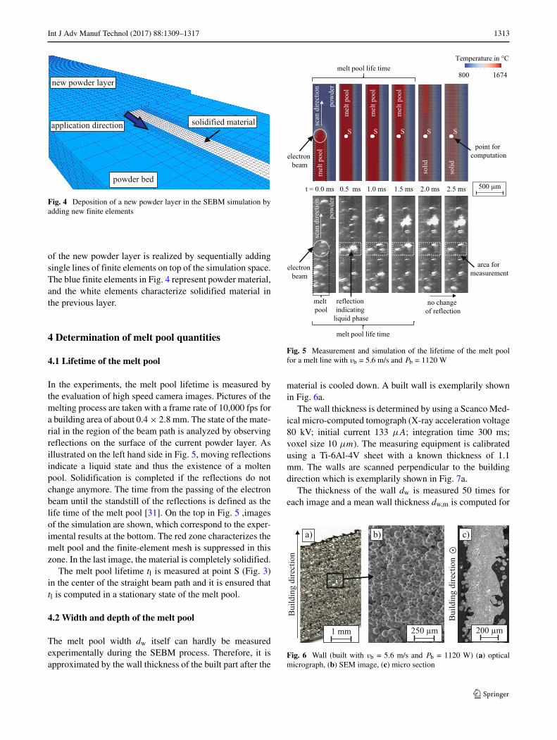
In the experiments, the melt pool lifetime is measured bythe evaluation of high speed camera images. Pictures of themelting process are taken with a frame rate of 10,000 fps fora building area of about 0.4× 2.8 mm. The state of the mate-rial in the region of the beam path is analyzed by observingreflections on the surface of the current powder layer. Asillustrated on the left hand side in Fig. 5, moving reflectionsindicate a liquid state and thus the existence of a moltenpool. Solidification is completed if the reflections do notchange anymore. The time from the passing of the electronbeam until the standstill of the reflections is defined as thelife time of the melt pool [31]. On the top in Fig. 5 ,imagesof the simulation are shown, which correspond to the exper-imental results at the bottom. The red zone characterizes themelt pool and the finite-element mesh is suppressed in thiszone. In the last image, the material is completely solidified.
The melt pool lifetime tl is measured at point S (Fig. 3)in the center of the straight beam path and it is ensured thattl is computed in a stationary state of the melt pool.
4.2 Width and depth of the melt pool
The melt pool width dw itself can hardly be measuredexperimentally during the SEBM process. Therefore, it isapproximated by the wall thickness of the built part after the
t = 0.0 ms 0.5 ms 1.0 ms 1.5 ms 2.0 ms 2.5 ms
melt
poolno change
of reflection
reflection
indicating
liquid phase
melt pool life time
area for
measurement
500 µm
electron
beam
scan
dir
ecti
on
pow
der
mel
t pool
mel
t pool
mel
t pool
mel
t pool
soli
d
soli
d
scan
dir
ecti
on
pow
der
Temperature in °C
800 1674melt pool life time
S S S S S
point for
computation
electron
beam
Fig. 5 Measurement and simulation of the lifetime of the melt poolfor a melt line with vb = 5.6 m/s and Pb = 1120 W
material is cooled down. A built wall is exemplarily shownin Fig. 6a.
The wall thickness is determined by using a Scanco Med-ical micro-computed tomograph (X-ray acceleration voltage80 kV; initial current 133 μA; integration time 300 ms;voxel size 10 μm). The measuring equipment is calibratedusing a Ti-6Al-4V sheet with a known thickness of 1.1mm. The walls are scanned perpendicular to the buildingdirection which is exemplarily shown in Fig. 7a.
The thickness of the wall dw is measured 50 times foreach image and a mean wall thickness dw,m is computed for
250 µm
b)
200 µm
c)
noitceri
dg
nidli
uB
noitceri
dg
nidli
uB
a)
1 mm
Fig. 6 Wall (built with vb = 5.6 m/s and Pb = 1120 W) (a) opticalmicrograph, (b) SEM image, (c) micro section
1314 Int J Adv Manuf Technol (2017) 88:1309–1317
200 µm
a) b)
dd
dw
dw
S
Fig. 7 (a) Measurement of the wall thickness for a built wall in a CTimage (b) melt pool width and depth in the simulation
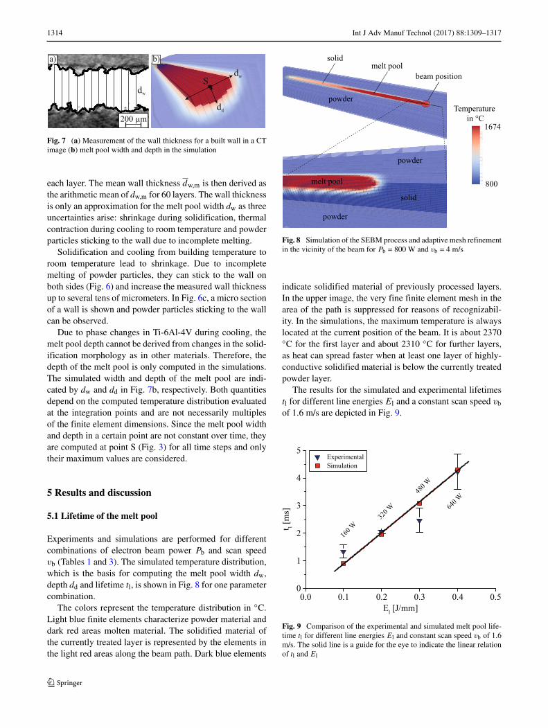
each layer. The mean wall thickness dw,m is then derived asthe arithmetic mean of dw,m for 60 layers. The wall thicknessis only an approximation for the melt pool width dw as threeuncertainties arise: shrinkage during solidification, thermalcontraction during cooling to room temperature and powderparticles sticking to the wall due to incomplete melting.
Solidification and cooling from building temperature toroom temperature lead to shrinkage. Due to incompletemelting of powder particles, they can stick to the wall onboth sides (Fig. 6) and increase the measured wall thicknessup to several tens of micrometers. In Fig. 6c, a micro sectionof a wall is shown and powder particles sticking to the wallcan be observed.
Due to phase changes in Ti-6Al-4V during cooling, themelt pool depth cannot be derived from changes in the solid-ification morphology as in other materials. Therefore, thedepth of the melt pool is only computed in the simulations.The simulated width and depth of the melt pool are indi-cated by dw and dd in Fig. 7b, respectively. Both quantitiesdepend on the computed temperature distribution evaluatedat the integration points and are not necessarily multiplesof the finite element dimensions. Since the melt pool widthand depth in a certain point are not constant over time, theyare computed at point S (Fig. 3) for all time steps and onlytheir maximum values are considered.
5 Results and discussion
5.1 Lifetime of the melt pool
Experiments and simulations are performed for differentcombinations of electron beam power Pb and scan speedvb (Tables 1 and 3). The simulated temperature distribution,which is the basis for computing the melt pool width dw,depth dd and lifetime tl, is shown in Fig. 8 for one parametercombination.
The colors represent the temperature distribution in ◦C.Light blue finite elements characterize powder material anddark red areas molten material. The solidified material ofthe currently treated layer is represented by the elements inthe light red areas along the beam path. Dark blue elements
melt pool
powder
powder
solid
Temperature
in °C1674
800
melt pool
powder
solid
beam position
Fig. 8 Simulation of the SEBM process and adaptive mesh refinementin the vicinity of the beam for Pb = 800 W and vb = 4 m/s
indicate solidified material of previously processed layers.In the upper image, the very fine finite element mesh in thearea of the path is suppressed for reasons of recognizabil-ity. In the simulations, the maximum temperature is alwayslocated at the current position of the beam. It is about 2370◦C for the first layer and about 2310 ◦C for further layers,as heat can spread faster when at least one layer of highly-conductive solidified material is below the currently treatedpowder layer.
The results for the simulated and experimental lifetimestl for different line energies El and a constant scan speed vbof 1.6 m/s are depicted in Fig. 9.
Fig. 9 Comparison of the experimental and simulated melt pool life-time tl for different line energies El and constant scan speed vb of 1.6m/s. The solid line is a guide for the eye to indicate the linear relationof tl and El

Int J Adv Manuf Technol (2017) 88:1309–1317 1315
Fig. 10 Comparison of the experimental and simulated melt poollifetime tl for different scan speeds vb
The error bars define the range of the standard devia-tion of the measured values. A good agreement between theexperimental and simulated values for tl is observed.
Figure 9 illustrates that for higher line energies El thelifetime tl becomes larger, since more energy is inducedinto the material and mainly conducted into the moltenmaterial due to its comparatively high heat conductivity.Hence, a longer time span is required for solidification. Theobserved relation between the line energy El and the meltpool lifetime tl is approximately linear in the simulationsand experiments.
The effect of the scan speed vb on the melt pool lifetimetl is shown in Fig. 10.
The life time of the melt pool tl is plotted as a function ofthe scan speed vb for different line energies El. The simu-lated and measured melt pool lifetimes coincide well for theinvestigated parameter combinations.
When the line energy El is kept constant and the scanspeed vb is increased, the lifetime of the melt pool remainsnearly constant. This tendency is found in the experimentsand the simulations.
Due to the good agreement between experiments andsimulations the developed simulation tool seems to be ableto predict the lifetime of the melt pool in the SEBM processof Ti-6Al-4V properly.
5.2 Width of the melt pool
The measured wall thickness dw,m is shown in Fig. 11 overthe height of the wall for one parameter combination.
The thickness dw,m increases only slightly over the wallheight. In the simulations, the computed melt pool width dwalso grows only marginally over the wall height. Therefore,
Fig. 11 Wall thickness over build height in experiments for Pb = 1120W and vb = 5.6 m/s
dw is only calculated (and averaged to dw,m) for the second,third and fourth layer to save computing time. The melt poolwidth of the first layer is not considered, since it is verydifferent from the following layers.
The experimental wall thickness and the simulated meltpool width are investigated for the parameter sets in theTables 1 and 3, respectively, and the results are illustrated inFig. 12.
The error bars characterize the range of the standard devi-ation of the measured wall thicknesses, which is with about200 μm for every parameter combination quite high dueto powder particles sticking on both sides of the wall. Dueto the same reason the experimental melt pool widths arehigher than the simulated ones. Another reason for the devi-ations might be that the dynamics of the melt pool [31] can
Fig. 12 Comparison of the experimental and simulated melt poolwidth for different scan speeds vb
1316 Int J Adv Manuf Technol (2017) 88:1309–1317
Fig. 13 Dependency of the melt pool depth dd on the scan speed vband the line energy El
not be captured by the thermal simulation. Therefore, theflow of the melt, which increases the dimensions of the meltpool, is not considered in the simulation.
The sets with line energy El of 0.2 J/mm show similarmelt pool widths for experiments (414 to 475 μm) and sim-ulations (344 to 352 μm), respectively. This was expected,since a similar amount of energy is induced into the mate-rial due to the same line energy. A similar melt pool widthis also observed for the simulations with a line energy of0.1, 0.3, and 0.4 J/mm, respectively. The simulations showfurther that the melt pool width increases nonlinearly withthe line energy. The influence of the line energy on the meltpool width decreases for higher line energies.
In summary, the experimental results coincide well withthe computed melt pool widths in the simulations.
5.3 Depth of the melt pool
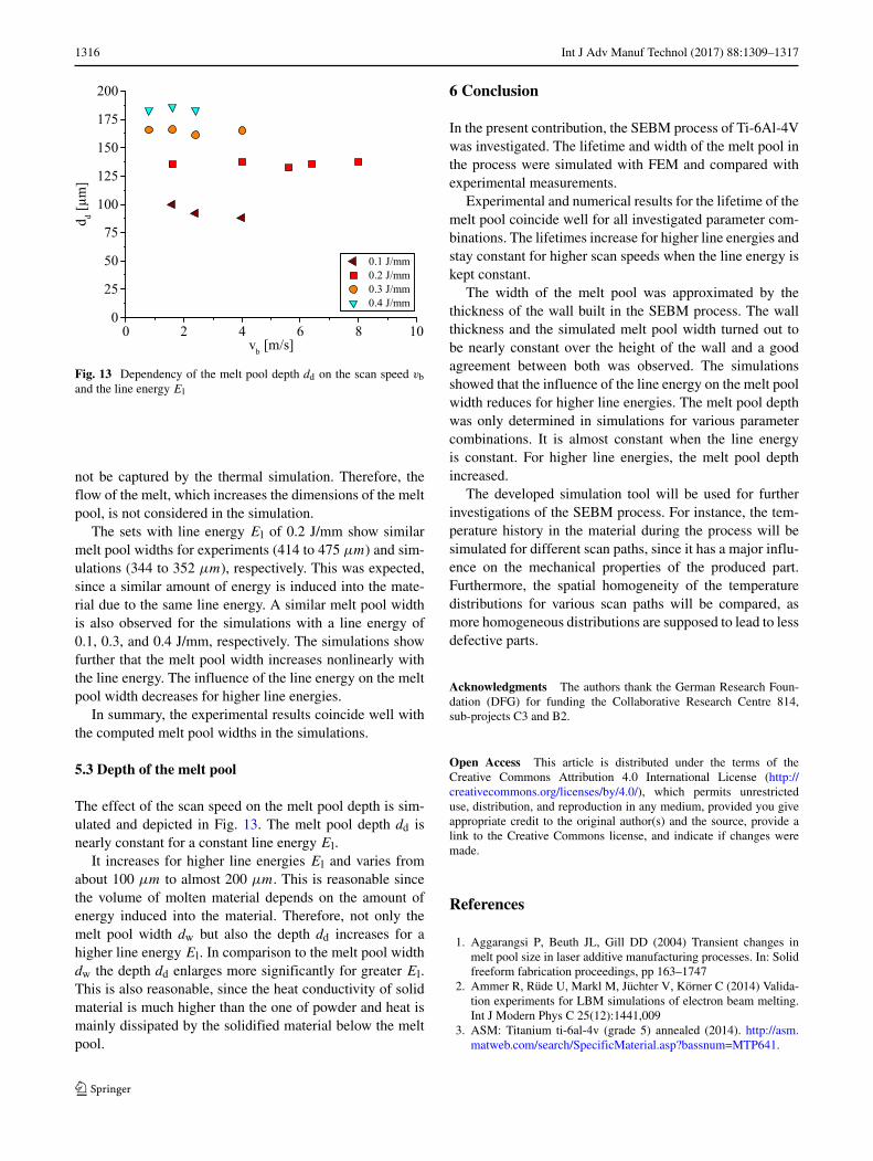
The effect of the scan speed on the melt pool depth is sim-ulated and depicted in Fig. 13. The melt pool depth dd isnearly constant for a constant line energy El.
It increases for higher line energies El and varies fromabout 100 μm to almost 200 μm. This is reasonable sincethe volume of molten material depends on the amount ofenergy induced into the material. Therefore, not only themelt pool width dw but also the depth dd increases for ahigher line energy El. In comparison to the melt pool widthdw the depth dd enlarges more significantly for greater El.This is also reasonable, since the heat conductivity of solidmaterial is much higher than the one of powder and heat ismainly dissipated by the solidified material below the meltpool.
6 Conclusion
In the present contribution, the SEBM process of Ti-6Al-4Vwas investigated. The lifetime and width of the melt pool inthe process were simulated with FEM and compared withexperimental measurements.
Experimental and numerical results for the lifetime of themelt pool coincide well for all investigated parameter com-binations. The lifetimes increase for higher line energies andstay constant for higher scan speeds when the line energy iskept constant.
The width of the melt pool was approximated by thethickness of the wall built in the SEBM process. The wallthickness and the simulated melt pool width turned out tobe nearly constant over the height of the wall and a goodagreement between both was observed. The simulationsshowed that the influence of the line energy on the melt poolwidth reduces for higher line energies. The melt pool depthwas only determined in simulations for various parametercombinations. It is almost constant when the line energyis constant. For higher line energies, the melt pool depthincreased.
The developed simulation tool will be used for furtherinvestigations of the SEBM process. For instance, the tem-perature history in the material during the process will besimulated for different scan paths, since it has a major influ-ence on the mechanical properties of the produced part.Furthermore, the spatial homogeneity of the temperaturedistributions for various scan paths will be compared, asmore homogeneous distributions are supposed to lead to lessdefective parts.
Acknowledgments The authors thank the German Research Foun-dation (DFG) for funding the Collaborative Research Centre 814,sub-projects C3 and B2.
Open Access This article is distributed under the terms of theCreative Commons Attribution 4.0 International License (http://creativecommons.org/licenses/by/4.0/), which permits unrestricteduse, distribution, and reproduction in any medium, provided you giveappropriate credit to the original author(s) and the source, provide alink to the Creative Commons license, and indicate if changes weremade.
References
1. Aggarangsi P, Beuth JL, Gill DD (2004) Transient changes inmelt pool size in laser additive manufacturing processes. In: Solidfreeform fabrication proceedings, pp 163–1747
2. Ammer R, Rude U, Markl M, Juchter V, Korner C (2014) Valida-tion experiments for LBM simulations of electron beam melting.Int J Modern Phys C 25(12):1441,009
3. ASM: Titanium ti-6al-4v (grade 5) annealed (2014). http://asm.matweb.com/search/SpecificMaterial.asp?bassnum=MTP641.

Int J Adv Manuf Technol (2017) 88:1309–1317 1317
Technical datasheet for Ti-6Al-4V from ASM AerospaceSpecifications Metals Inc.
4. Bangerth W, Hartmann R, Kanschat G (2007) deal.II - a general-purpose object-oriented finite element library. ACM Trans MathSoftw (TOMS) 33(4):24
5. Baumers M, Tuck C, Hague R, Ashcroft I, Wildman R (2010) Acomparative study of metallic additive manufacturing power con-sumption. In: Proceedings of the 2010 solid freeform fabricationsymposium
6. Bikas H, Stavropoulos P, Chryssolouris G (2015) Additive manu-facturing methods and modelling approaches: a critical review. IntJ Adv Manuf Technol:1–17
7. BoivineauM, Cagran C, Doytier D, Eyraud V, Nadal MH,WilthanB, Pottlacher G (2006) Thermophysical properties of solid andliquid Ti-6Al-4V alloy. Int J Thermophys 27(2):507–529
8. Carpenter: Titanium alloy Ti-6Al-4V (2014). http://cartech.ides.com. Technical datasheet for Ti-6Al-4V from Carpenter
9. Chen YX, Wang XJ, Chen SB (2014) The effect of electron beamenergy density on temperature field for electron beam melting.Adv Mater Res 900:631–638
10. Cormier D, Harrysson O, West H (2004) Characterization ofH13 steel produced via electron beam melting. Rapid Prototyp J10(1):35–41
11. Denlinger ER, Heigel JC, Michaleris P (2014) Residual stress anddistortion modeling of electron beam direct manufacturing Ti-6Al-4V. In: Proceedings of the institution of mechanical engineers, partb: journal of engineering manufacture p 0954405414539494
12. Ellsiepen P. (1999) Zeit- und ortsadaptive Verfahren angewandtauf Mehrphasenprobleme poroser Medien. Inst. fur Mechanik(Bauwesen), Ph.D. thesis
13. Frigola P, Harrysson O, Horn T, Ramirez D, Murr L (2014) Fabri-cating copper components with electron beam melting. Adv MaterProcess 172(7):20–24
14. Gaytan S, Murr L, Martinez E, Martinez J, Machado B, RamirezD, Medina F, Collins S, Wicker R (2010) Comparison ofmicrostructures and mechanical properties for solid and meshcobalt-base alloy prototypes fabricated by electron beam melting.Metallurg Mater Trans A 41(12):3216–3227
15. Harrysson O, Cormier D, Marcellin-Little D, Jajal K (2003) Directfabrication of metal orthopedic implants using electron beammelting technology. In: Solid freeform fabrication symposiumproceedings, pp 439–446
16. Heinl P, Muller L, Korner C, Singer RF, Muller FA (2008) Cellu-lar Ti–6Al–4V structures with interconnected macro porosity forbone implants fabricated by selective electron beam melting. ActaBiomaterialia 4(5):1536–1544
17. Heinl P, Rottmair A, Korner C, Singer RF (2007) Cellular titaniumby selective electron beam melting. Adv Eng Mater 9(5):360–364
18. Jamshidinia M, Kong F, Kovacevic R (2013) The coupled CFD-FEM model of electron beam melting. ASME District F - EarlyCareer Tech Conf Proc 12:163–171
19. Juechter V, Scharowsky T, Singer R, Korner C (2014) Process-ing window and evaporation phenomena for Ti–6Al–4V produced
by selective electron beam melting. Acta Materialia 76:252–258
20. Karunakaran K, Bernard A, Suryakumar S, Dembinski L, Tail-landier G (2012) Rapid manufacturing of metallic objects. RapidPrototyp J 18(4):264–280
21. Kaschnitz E, Reiter P, McClure J (2002) Thermophysical prop-erties of solid and liquid 90Ti–6Al–4V in the temperature rangefrom 1400 to 2300 K measured by millisecond and microsecondpulse-heating techniques. Int J Thermophys 23(1):267–275
22. Klassen A, Bauereiß A, Korner C (2014) Modelling of electronbeam absorption in complex geometries. J Phys D: Appl Phys47(6):065,307
23. Korner C, Attar E, Heinl P (2011) Mesoscopic simulation of selec-tive beammelting processes. J Mater Process Technol 211(6):978–987
24. Markl M, Ammer R, Rude U, Korner C (2014) Improving hatch-ing strategies for powder bed based additive manufacturing withan electron beam by 3D simulations. CoRR arXiv:1403.3251
25. Murr L, Gaytan S, Medina F, Martinez E, Martinez J, Hernan-dez D, Machado B, Ramirez D, Wicker R (2010) Characteri-zation of Ti–6Al–4V open cellular foams fabricated by additivemanufacturing using electron beam melting. Mater Sci Eng A527(7):1861–1868
26. Murr L, Martinez E, Gaytan S, Ramirez D, Machado B, Shindo P,Martinez J, Medina F, Wooten J, Ciscel D et al (2011) Microstruc-tural architecture, microstructures, and mechanical properties fora nickel-base superalloy fabricated by electron beam melting.Metallurg Mater Trans A 42(11):3491–3508
27. Rai R, Burgardt P, Milewski J, Lienert T, DebRoy T (2009)Heat transfer and fluid flow during electron beam welding of21Cr–6Ni–9Mn steel and Ti–6Al–4V alloy. J Phys D: Appl Phys42(2):025,503
28. Ramirez D, Murr L, Li S, Tian Y, Martinez E, Martinez J,Machado B, Gaytan S, Medina F, Wicker R (2011) Open-cellularcopper structures fabricated by additive manufacturing using elec-tron beam melting. Mater Sci Eng A 528(16):5379–5386
29. Ramirez D, Murr L, Martinez E, Hernandez D, Martinez J,Machado B, Medina F, Frigola P, Wicker R (2011) Novelprecipitate–microstructural architecture developed in the fabrica-tion of solid copper components by additive manufacturing usingelectron beam melting. Acta Mater 59(10):4088–4099
30. Riedlbauer D, Steinmann P, Mergheim J (2014) Thermomechan-ical finite element simulations of selective electron beam meltingprocesses: performance considerations. Comput Mech 54(1):109–122
31. Scharowsky T, Osmanlic F, Singer R, Korner C (2014) Melt pooldynamics during selective electron beam melting. Appl Phys A114(4):1303–1307
32. Shen N, Chou Y (2012) Numerical thermal analysis in electronbeam additive manufacturing with preheating effects. In: Pro-ceedings of the 23rd solid freeform fabrication symposium, pp774–784
33. Zah MF, Lutzmann S (2010) Modelling and simulation of electronbeam melting. Product Eng 4(1):15–23