macintosh powerbook g3 series - higher...
TRANSCRIPT

Developer Note
5/6/98Technical Publications© Apple Computer, Inc. 1998
Developer Note
Macintosh PowerBook G3 Series

Apple Computer, Inc.© 1998 Apple Computer, Inc.All rights reserved. No part of this publication may be reproduced, stored in a retrieval system, or transmitted, in any form or by any means, mechanical, electronic, photocopying, recording, or otherwise, without prior written permission of Apple Computer, Inc., except to make a backup copy of any documentation provided on CD-ROM. The Apple logo is a trademark of Apple Computer, Inc. Use of the “keyboard” Apple logo (Option-Shift-K) for commercial purposes without the prior written consent of Apple may constitute trademark infringement and unfair competition in violation of federal and state laws. No licenses, express or implied, are granted with respect to any of the technology described in this book. Apple retains all intellectual property rights associated with the technology described in this book. This book is intended to assist application developers to develop applications only for Apple-labeled or Apple-licensed computers.Every effort has been made to ensure that the information in this manual is accurate. Apple is not responsible for typographical errors.Apple Computer, Inc.1 Infinite LoopCupertino, CA 95014408-996-1010
Apple, the Apple logo, and Macintosh are trademarks of Apple Computer, Inc., registered in the United States and other countries.Adobe, Acrobat, and PostScript are trademarks of Adobe Systems Incorporated or its subsidiaries and may be registered in certain jurisdictions.
Helvetica and Palatino are registered trademarks of Linotype-Hell AG and/or its subsidiaries.ITC Zapf Dingbats is a registered trademark of International Typeface Corporation.QuickView™ is licensed from Altura Software, Inc.
Simultaneously published in the United States and Canada.
Even though Apple has reviewed this manual, APPLE MAKES NO WARRANTY OR REPRESENTATION, EITHER EXPRESS OR IMPLIED, WITH RESPECT TO THIS MANUAL, ITS QUALITY, ACCURACY, MERCHANTABILITY, OR FITNESS FOR A PARTICULAR PURPOSE. AS A RESULT, THIS MANUAL IS SOLD “AS IS,” AND YOU, THE PURCHASER, ARE ASSUMING THE ENTIRE RISK AS TO ITS QUALITY AND ACCURACY.
IN NO EVENT WILL APPLE BE LIABLE FOR DIRECT, INDIRECT, SPECIAL, INCIDENTAL, OR CONSEQUENTIAL DAMAGES RESULTING FROM ANY DEFECT OR INACCURACY IN THIS MANUAL, even if advised of the possibility of such damages.
THE WARRANTY AND REMEDIES SET FORTH ABOVE ARE EXCLUSIVE AND IN LIEU OF ALL OTHERS, ORAL OR WRITTEN, EXPRESS OR IMPLIED. No Apple dealer, agent, or employee is authorized to make any modification, extension, or addition to this warranty.
Some states do not allow the exclusion or limitation of implied warranties or liability for incidental or consequential damages, so the above limitation or exclusion may not apply to you. This warranty gives you specific legal rights, and you may also have other rights which vary from state to state.
Contents
Figures and Tables vii
Preface About This Developer Note ix
Contents of This Note ixSupplemental Reference Documents ixConventions and Abbreviations x
Typographical Conventions xStandard Abbreviations xi
Chapter 1 Introduction 15
Features 16Peripheral Devices 18Compatibility Issues 18
Expansion Bay Modules 18RAM Expansion Modules 19Machine Identification 19System Software 19
Chapter 2 Architecture 21
System Module 22G3 Microprocessor 22Backside Cache 24Bus Clock Speeds 24Memory Controller and PCI Bridge 24
I/O board 25I/O Controller ICs 25
Functions of the I/O Controllers 25Features of the I/O Controllers 26
Video Controller IC 27Power Management Unit 27
iii

Screamer Sound IC 28CardBus Controller IC 28
Chapter 3 I/O Features 29
Hard Disk Drive 30Hard Disk Specifications 31Hard Disk Connector 33
Signal Assignments 34ATA Signal Descriptions 35
Trackpad 36Keyboard 37Flat Panel Display 39External Video Connectors 39
Monitors Supported 40Monitor Connector 42Monitor Adapter 43Monitor Sense Codes 43External Video Connector 45
Serial Port 47SCSI Port 48ADB Port 49Infrared Communication Link 51Sound System 51
Sound Inputs 52Built-in Microphone 52External Sound Input 53Expansion Bay Sound Input 53CardBus Sound Input 53
Sound Outputs 53External Sound Output 54Internal Speakers 54Communication Slot 54
Ethernet Port 54Internal Modem 55
iv

Chapter 4 Expansion Features 57
Expansion Bays 58Mechanical Design of Expansion Bay Modules 59Expansion Bay Connectors 59
ATA and Floppy Disk Signals on the Expansion Bay Connector 62ATA and Floppy Disk Signal Definitions 64Unused IDE Signals on the Expansion Bay Connector 67Power on the Expansion Bay Connector 67PCI Signals on the Right Expansion Bay Connector 68PCI Control Signals in Sleep Mode 70PCI Signals During Power On and Off 71Power Sequences 73
User Installation of an Expansion Bay Module 75Sequence of Control Signals 75Guidelines for Developers 76
RAM Expansion Slots 76Mechanical Design of RAM SO-DIMMs 77Electrical Design of RAM SO-DIMMs 77
SDRAM Devices 78Configuration of RAM SO-DIMMs 79Address Multiplexing 80
RAM SO-DIMM Electrical Limits 81CardBus Slot 81
Index 83
v


Figures and Tables
Chapter 2 Architecture 21
Figure 2-1 Block diagram 23
Table 2-1 Clock speeds 24
Chapter 3 I/O Features 29
Figure 3-1 Maximum dimensions of the internal hard disk 32Figure 3-2 Hard disk connector and location 33Figure 3-3 Keyboard and embedded keypad 38Figure 3-4 Signal pins on the video connector 42Figure 3-5 S-video connector 45Figure 3-6 Serial port connector 47Figure 3-7 ADB connector 50
Table 3-1 Pin assignments on the ATA hard disk connector 34Table 3-2 Signals on the ATA hard disk connector 35Table 3-3 Types of displays 39Table 3-4 Picture sizes supported 40Table 3-5 Monitors and picture sizes 41Table 3-6 Signals on the video connector 42Table 3-7 Monitor sense codes 44Table 3-8 Pin assignments for the S-video output connector 46Table 3-9 Picture sizes for composite video output 46Table 3-10 Pin assignments on the serial port connector 47Table 3-11 SCSI connector signals 48Table 3-12 ADB connector pin assignments 50
Chapter 4 Expansion Features 57
Figure 4-1 Section through expansion bay connector 61Figure 4-2 Timing of expansion bay control signals for sleep mode 71Figure 4-3 Timing of the expansion bay control signals during power on 72Figure 4-4 Timing of the expansion bay control signals during power off 72
vii

Table 4-1 Devices supported by the expansion bays 58Table 4-2 Device ID signals and types of devices 62Table 4-3 ATA and floppy disk signals on the expansion bay connector 62Table 4-4 Audio and control signals on the expansion bay connector 65Table 4-5 Floppy disk signals on the expansion bay connector 65Table 4-6 ATA signals on the expansion bay connector 66Table 4-7 Unused IDE signals on the expansion bay connector 67Table 4-8 Power lines on the expansion bay connector 67Table 4-9 PCI signals on the expansion bay connector 68Table 4-10 Sizes of RAM expansion modules and devices 79Table 4-11 Types of DRAM devices 80
viii

P R E F A C E
About This Developer Note
This developer note is a concise description of the Macintosh PowerBook G3 Series computers, with the emphasis on the features that are new or different from those of earlier Macintosh PowerBook computers.
This developer note is intended to help hardware and software developers design products that are compatible with the Macintosh products described here. If you are not already familiar with Macintosh computers or if you would simply like additional technical information, you may wish to read the supplementary reference documents described in this preface.
Contents of This Note 0
The information in this note is arranged in four chapters.
Chapter 1, “Introduction,” introduces the Macintosh PowerBook G3 Series computers and describes their features.
Chapter 2, “Architecture,”describes the internal logic of the computers, including the main ICs.
Chapter 3, “I/O Features,”describes the standard I/O ports and the built-in I/O devices.
Chapter 4, “Expansion Features,” describes the expansion features of interest to developers. It includes development guides for expansion-bay devices, the RAM expansion modules, and the PC card slot.
Supplemental Reference Documents 0
For a description of the version of the Mac OS that comes with the new models, developers should refer to the Technote for Mac OS 8.1. The technote is available on the Technote web site at
ix

P R E F A C E
http://devworld.apple.com/dev/technotes.shtml
For the latest information about the system software for ATA devices such as the IDE drive, see Technote #1098, ATA Device Software Guide Additions and Corrections, available on the world wide web at
http://www.devworld.apple.com/dev/technotes/tn/tn1098.html
The web page for Technote #1098 includes a link to a downloadable copy of ATA Device Software Guide.
Printed copies of the technotes are available from Field Copy and Printing, telephone 1-415-323-3155. The technotes are also available on the reference library issues of the developer CD.
For more information about the PowerPC 750™ microprocessor used in the Macintosh PowerBook G3 Series computers, developers may wish to refer to the standard reference, PowerPC 740/750 Microprocessor Implementation Definition Book IV. Information about the PowerPC 750 and other G3 microprocessors is also available on the World Wide Web at
http://www.mot.com/SPS/PowerPC/index.html
Developers should also have copies of the relevant books of the Inside Macintosh series, available in technical bookstores.
Conventions and Abbreviations 0
This developer note uses the following typographical conventions and abbreviations.
Typographical Conventions 0
Computer-language text—any text that is literally the same as it appears in computer input or output—appears in Courier font.
Hexadecimal numbers are preceded by a dollar sign ($). For example, the hexadecimal equivalent of decimal 16 is written as $10.]
NoteA note like this contains information that is of interest but is not essential for an understanding of the text.
x

P R E F A C E
IMPORTANT
A note like this contains important information that you should read before proceeding.
W AR N I N G
Warnings like this direct your attention to something that could cause injury to the user, damage to either hardware or software, or loss of data.
Standard Abbreviations 0
Standard units of measure used in this note include
Other abbreviations used in this note include
A amperes MHz megahertz
dB decibels mm millimeters
GB gigabytes ms milliseconds
Hz hertz mV millivolts
K 1024 µF microfarads
KB kilobytes µW microwatts
kbps kilobits per second ns nanoseconds
kHz kilohertz Ω ohms
kΩ kilohms pF picofarads
M 1,048,576 V volts
mA milliamperes VAC volts alternating current
MB megabytes VDC volts direct current
Mbps megabits per second W watts
$n hexadecimal value n
AC alternating current
ADB Apple Desktop Bus
API application program interface
ASIC application-specific integrated circuit
ATA AT attachment
xi

P R E F A C E
ATAPI ATA packet interface
AUI auxiliary unit interface
BCD binary coded decimal
BGA ball grid array
CAS column address strobe (a memory control signal)
CCFL cold cathode fluorescent lamp
CD compact disc
CIS card information structure
CLUT color lookup table
CMOS complementary metal oxide semiconductor
CPU central processing unit
DAA data access adapter (a telephone line interface)
DAC digital-to-analog converter
DC direct current
DCE device control entry (a data structure)
DDC display data channel
DDM driver descriptor map
DMA direct memory access
DMF distribution media format
DOS disk operating system
DRAM dynamic RAM
DSP digital signal processor
DSVD digital simultaneous voice and data
EDO extended data out
EIDE extended IDE
FIFO first in, first out
FPU floating-point unit
HBA host bus adapter
IC integrated circuit
IDE integrated device electronics
xii

P R E F A C E
I/O input/output
IR infrared
IrDA Infrared Data Association
L2 level 2 or second level, a type of cache
LCD liquid crystal display
LS TTL low-power Schottky TTL
LVDS low voltage differential signaling
MMU memory management unit
NiCad nickel cadmium
NiMH nickel metal hydride
PC card an expansion card conforming to the specifications of the PCMCIA
PCI Peripheral Component Interconnect
PCMCIA Personal Computer Memory Card International Association
PDS processor-direct slot
PGA pin grid array
PLL phase-locked loop
PMU power management unit
PQFP plastic quad flatpack package
PROM programmable read-only memory
PWM pulse width modulation
RAM random-access memory
RAMDAC random-access memory, digital to analog converter
RAS row address strobe
RGB red-green-blue
RISC reduced instruction set computing
rms root-mean-square
ROM read-only memory
SCC Serial Communications Controller
SCSI Small Computer System Interface
SGRAM synchronous graphics RAM
xiii

P R E F A C E
SNR signal-to-noise ratio
SO DIMM small outline dual inline memory module
SOJ small outline J-lead package
SOP small outline package
SPD Serial Presence Detect, a feature of the SO DIMM
STN supertwist nematic (a type of LCD)
SVGA super video graphics adapter
TDM time division multiplexing
TFT thin-film transistor (a type of LCD)
TQFP thin quad flatpack package
TSOP thin small outline package
TTL transistor-transistor logic
VCC positive supply voltage (voltage for collectors)
VGA video graphics adapter
VRAM video RAM; used for display buffers
WRAM window RAM; used for display buffers
XGA extended video graphics adapter
xiv

C H A P T E R 1
Figure 1-0Listing 1-0Table 1-0
Introduction 1
15

C H A P T E R 1
Introduction
The Macintosh PowerBook G3 Series computers have a scalable design that encompasses a high-performance laptop computer as well as a low-cost laptop computer with many of the same features. This chapter summarizes the features of the Macintosh PowerBook G3 Series computers, lists available peripheral devices, and points out issues affecting compatibility.
Features 1
Here is a list of the features of the Macintosh PowerBook G3 Series computers. Each feature is described in a later chapter, as indicated in the list.
Processor: The microprocessor in the Macintosh PowerBook G3 Series computers is a PowerPC G3 microprocessor running at a clock speed of 233, 250, or 292 MHz. See “G3 Microprocessor” (page 22).
Cache: The 250- and 292-MHz models have a backside L2 cache consisting of 1 MB of fast static RAM. The clock speed for the backside cache is half the clock speed of the microprocessor. See “Backside Cache” (page 24).
Memory: The Macintosh PowerBook G3 Series computers have two standard SO-DIMM expansion slots for SDRAM modules. The computers come with 16, 32, or 64 MB of SDRAM installed. RAM is expandable up to 192 MB total, using presently available memory devices. See “RAM Expansion Slots” (page 76).
Hard disk storage: The Macintosh PowerBook G3 Series computers have built-in hard disk drives with capacities of 2, 4, or 8 GB. The hard drive is removable. For more information and developer guidelines for alternative hard drives, see “Hard Disk Drive” (page 30).
Display: The Macintosh PowerBook G3 Series computers have either a 13.3- or 14.1-inch TFT display with XGA resolution (1024 x 768 pixels) or a 12.1-inch STN display with SVGA resolution (800 x 600 pixels). Each display is backlit by a cold cathode fluorescent lamp (CCFL). See “Flat Panel Display” (page 39).
External monitor: All configurations have a standard VGA video connector for an external video monitor with XGA resolution (up to 1280 x 960 pixels). In addition, the 13.3- and 14.1-inch models have an S-video connector that supports PAL and NTSC video monitors. See “External Video Connectors” (page 39).
16 Features

C H A P T E R 1
Introduction
Video RAM: The Macintosh PowerBook G3 Series computers come with 2 or 4 MB of video SGRAM, which supports up to millions of colors on an external monitor. See “Flat Panel Display” (page 39) and “External Video Connectors” (page 39).
Graphics acceleration: The video circuits provide built-in 2D and 3D acceleration. See “Video Controller IC” (page 27).
Expansion bays: All configurations have two expansion bays for batteries, floppy disk drive, CD-ROM drive, DVD drive, and other IDE or PCI devices. Storage devices in the expansion bays can be removed and replaced while the computer is operating. See “Expansion Bays” (page 58).
CardBus slot: All configurations have a CardBus slot that accepts one Type III or two Type II CardBus cards or PC Cards. The cards can be removed and replaced while the computer is operating. The slot supports Zoomed Video. See “CardBus Slot” (page 81).
Standard I/O ports: All configurations have the standard Macintosh input and output ports:
External SCSI with an HDI-30 connector; see “SCSI Port” (page 48) Serial port with GeoPort capability; see “Serial Port” (page 47) Audio input and output ports; see “Sound System” (page 51) ADB port for external keyboard or mouse; see “ADB Port” (page 49)
Modem: Some configurations have a built-in modem with K56flex data rate. See “Internal Modem” (page 55).
Ethernet: All configurations have a built in Ethernet port with a 10BaseT connector. See “Ethernet Port” (page 54)
Infrared link: All configurations have an infrared link for up to 4 Mbit-per-second IrDA data transfer. See “Infrared Communication Link” (page 51)
Sound: All configurations have a built-in microphone and speakers as well as a line-level stereo input jack and a stereo headphone jack. See “Sound System” (page 51)
Keyboard: The keyboard is a new design with an embedded numeric keypad and inverted-T arrow keys. See “Keyboard” (page 37).
Trackpad: The integrated flat pad includes tap/double tap and drag features. See “Trackpad” (page 36).
Features 17

C H A P T E R 1
Introduction
Weight: A Macintosh PowerBook G3 Series computer weighs 3.45 kg (7.6 pounds) with the battery and CD-ROM drive installed in the expansion bays.
Size: A Macintosh PowerBook G3 Series computer is 323 mm (12.83 inches) wide, 265 mm (10.43 inches) deep, and 51 mm (2.01 inches) thick.
Peripheral Devices 1
In addition to the devices that are included with the computers, several peripheral devices are available separately:
The Macintosh PowerBook G3 Series Floppy Disk Drive is available separately for models that do not include it.
The Macintosh PowerBook G3 Series DVD-ROM drive module, which fits into the right expansion bay, is available at the time of purchase as a build-to-order option.
The Macintosh PowerBook G3 Series Intelligent Lithium Ion Battery is available separately as an additional or replacement battery.
The Macintosh PowerBook 45W AC Adapter, which comes with the computer, is also available separately. The adapter can recharge the internal battery in four hours while the computer is running or in two hours while the computer is shut down or in sleep mode.
Compatibility Issues 1
While the Macintosh PowerBook G3 Series computers have many new features, there should be no compatibility problems with applications and peripherals that operate correctly with earlier PowerBook models, with the exceptions described in this section.
Expansion Bay Modules 1
The expansion bays in the Macintosh PowerBook G3 Series computers are not the same as those in the PowerBook G3 and PowerBook 3400 computers. Expansion bay modules designed for earlier PowerBook computers will not fit
18 Peripheral Devices
C H A P T E R 1
Introduction
in the Macintosh PowerBook G3 Series computers. For more information, see “Expansion Bays” (page 58).
RAM Expansion Modules 1
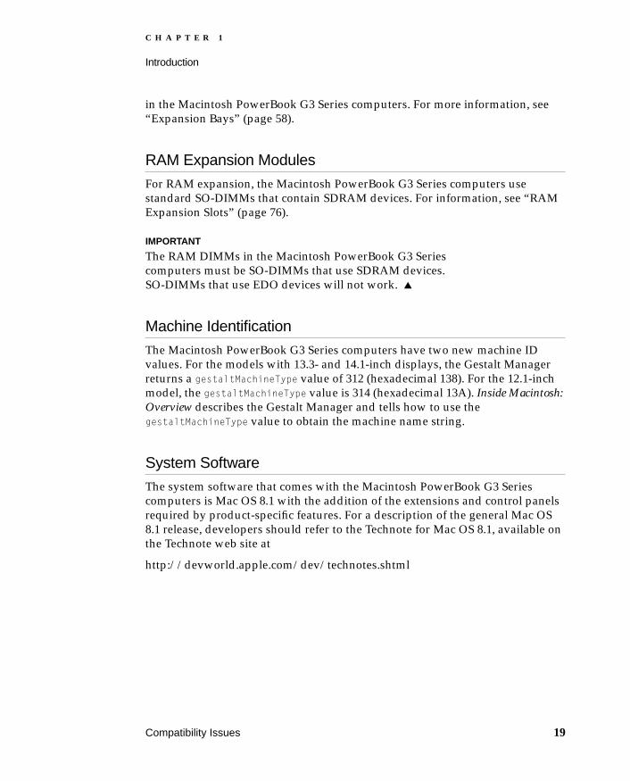
For RAM expansion, the Macintosh PowerBook G3 Series computers use standard SO-DIMMs that contain SDRAM devices. For information, see “RAM Expansion Slots” (page 76).
IMPORTANT
The RAM DIMMs in the Macintosh PowerBook G3 Series computers must be SO-DIMMs that use SDRAM devices. SO-DIMMs that use EDO devices will not work.
Machine Identification 1
The Macintosh PowerBook G3 Series computers have two new machine ID values. For the models with 13.3- and 14.1-inch displays, the Gestalt Manager returns a gestaltMachineType value of 312 (hexadecimal 138). For the 12.1-inch model, the gestaltMachineType value is 314 (hexadecimal 13A). Inside Macintosh: Overview describes the Gestalt Manager and tells how to use the gestaltMachineType value to obtain the machine name string.
System Software 1
The system software that comes with the Macintosh PowerBook G3 Series computers is Mac OS 8.1 with the addition of the extensions and control panels required by product-specific features. For a description of the general Mac OS 8.1 release, developers should refer to the Technote for Mac OS 8.1, available on the Technote web site at
http://devworld.apple.com/dev/technotes.shtml
Compatibility Issues 19

C H A P T E R 1
Introduction
W AR N I N G
There are several types of programs that may be incompatible with Mac OS 8.1 and the new Mac OS Extended format: utilities that check the integrity of a disk volume, programs that provide password security for volumes, and other programs that write data directly to a volume. The use of these programs with a disk that has been formatted in the extended format may result in loss of data.
20 Compatibility Issues

C H A P T E R 2
Figure 2-0Listing 2-0Table 2-0
Architecture 2
21

C H A P T E R 2
Architecture
The architecture of the Macintosh PowerBook G3 Series computers is designed around two main circuit boards: the system module and the I/O board. The devices on the system module communicate with the devices on the I/O board by way of the PCI bus. Figure 2-1 is a block diagram showing the major components and the relationship of the system module and the I/O board.
System Module 2
The system module contains the high-speed components: the microprocessor, the backside cache, the main memory, and the IC that contains the memory controller and the PCI bus bridge.
This section includes a description of the microprocessor, the cache, and the memory controller IC. For a description of the SO-DIMMs that contain the main memory, please see the section “RAM Expansion Slots” (page 76).
G3 Microprocessor 2
The latest family of PowerPC microprocessor designs is called “G3,” for “generation three.” The G3 microprocessors have several features that contribute to improved performance, including:
larger on-chip (L1) caches, 32 KB each for instruction cache and data cache
a built-in cache controller and cache tag RAM for the second level (L2) cache
a separate backside bus for the L2 cache, providing faster clock speed and overlapped bus transactions
a microprocessor core optimized for Mac OS applications
The G3 microprocessor in the Macintosh PowerBook G3 Series computers runs at a clock speed of either 233, 250, or 292 MHz, depending on the model. Table 2-1 (page 24) shows how the speeds of the CPU clock, the backside cache, and the main memory bus are related.
The PowerPC G3 family of microprocessors includes the PowerPC 740™ and the PowerPC 750™; the Macintosh PowerBook G3 Series computers use the PowerPC 750.
22 System Module

C H A P T E R 2
Architecture
Figure 2-1 Block diagram
Gracklememorycontrollerand PCI
bus bridge
ROM
RAMSO-DIMM
RAMSO-DIMM
SRAM
Sound in
Sound out
Serial port
IrDA link
SCSI
External video
PCI bus
L2cacheSRAM
System module
I/O board
ADB port
Keyboard
Power
Trackpad
Address
Data
Zoom video
Address
Data
PowerPCG3
micro-processor
PMUpower
managerIC
Screamersound IC
Heathrow#1
I/O anddisk
controller
Heathrow#2
I/O anddisk
controller
Internal EIDEhard disk
Communicationsslot
VideoSGRAM
Flatpanel
display
3D Rage LTvideo
controller
Leftexpansion
bay
Rightexpansion
bay
CardBusslotPCI1131
CardBusbridge
Ethernet
System Module 23

C H A P T E R 2
Architecture
Backside Cache 2
The backside cache controller and the cache tag storage are built into the microprocessor chip. The cache controller includes bus management and control hardware that allows the cache to run at an independent sub-multiple of the processor’s clock speed, rather than at the clock speed of the main system bus. In the Macintosh PowerBook G3 Series computers, the clock speed of the backside cache is half that of the microprocessor.
The data storage for the backside L2 cache consists of 1 MB of fast static RAM on the system module.
NoteThe 233-MHz model does not include a backside cache.
Bus Clock Speeds 2
Table 2-1 shows the clock speeds for the microprocessor, the backside cache, and the main buses in the Macintosh PowerBook G3 Series computers.
Memory Controller and PCI Bridge 2
The memory controller and PCI bus bridge IC is a Motorola MPC106, also called Grackle. The Grackle IC provides the bus bridge between the processor bus used on the system module and the PCI bus used for the I/O controllers on the I/O board. The Grackle IC also contains the controller for the main memory.
To enhance performance, the Grackle IC supports concurrent transactions on the main memory bus and the PCI bus.
Table 2-1 Clock speeds
Bus or device Clock speeds
G3 microprocessor 233.3 MHz 250.0 MHz 291.6 MHz
Backside L2 cache — 125.0 MHz 145.8 MHz
System bus 66.7 MHz 83.3 MHz 83.3 MHz
PCI bus 33.3 MHz 33.3 MHz 33.3 MHz
24 System Module

C H A P T E R 2
Architecture
I/O board 2
All the I/O interfaces, the video and display support, the expansion bays, and the CardBus slots are on the I/O board. The controller ICs on the I/O board are connected to the PCI bus.
I/O Controller ICs 2
The Macintosh PowerBook G3 Series computers have two Heathrow I/O controller ICs. The Heathrow IC is an integrated I/O controller and DMA engine for use in Power Macintosh computers with a PCI bus. It integrates most of the standard Macintosh I/O controllers, including SCSI, SCC, IDE, floppy disk, sound, Ethernet, and VIA.
Functions of the I/O Controllers 2
Heathrow number 1 provides the interface and control signals for
the serial port
the infrared link
the Ethernet port
the Screamer sound IC
the internal IDE hard drive
the external SCSI port
the right expansion bay, including enhanced IDE, floppy disk, and PCI interfaces
the power manager IC, described in “Power Management Unit” (page 27)
SPD (serial presence detect) for the bottom SDRAM SO-DIMM and the configuration ROM
Heathrow number 2 provides the interface and control signals for
the communications card
the left expansion bay, including enhanced IDE and floppy disk drives
I/O board 25

C H A P T E R 2
Architecture
SPD (serial presence detect) for the top SDRAM SO-DIMM
NoteFor detailed descriptions of the expansion bays, please see “Expansion Bays” (page 58).
Features of the I/O Controllers 2
Here are the features of the Heathrow ICs.
A 33MHz PCI Bus interface with both master and slave transactions
A Gated Clocks PCI arbiter
An SCSI controller implemented using the Mesh design
Two Enhanced IDE channels
An 85C30 SCC cell that supports GeoPort™ and has additional support for LocalTalk
An SWIM3 unit that supports 3.5-inch floppy drives and off-loads time-critical low-level tasks from the CPU.
The interface to the Screamer external sound chip
A VIA cell
The interface to the PMU, described in “Power Management Unit” (page 27)
A general purpose, 16-bit parallel port that supports the sound multiplex controller, the expansion bay, and the IDE channels.
A DMA controller with a channel dedicated to each I/O port. The DMA controller performs scatter/gather transfers based on a buffer list in main memory.
Certain control functions including media bay support and sleep mode.
Desktop functions including support for front panel push-buttons and control of screen illumination and fan speed.
A 10 Mbit-per-second Ethernet interface.
The Heathrow IC includes all the features of the O’Hare I/O controller used in the PowerBook 3400 and the PowerBook G3, along with a few new features. Here are the differences between the Heathrow and O’Hare ICs:
26 I/O board

C H A P T E R 2
Architecture
Heathrow includes support for 10Mbit Ethernet; O’Hare does not include Ethernet support.
Heathrow supports Enhanced IDE; O’Hare supports IDE but not EIDE.
Heathrow uses the Gated Clocks PCI arbiter; O’Hare uses a sub-set of the Gated Clocks PCI arbiter.
Heathrow supports additional interrupts.
Heathrow includes an MFM floppy-disk controller.
Video Controller IC 2
The video controller in the Macintosh PowerBook G3 Series computers is an ATI RAGE LT IC operating on the PCI bus. The RAGE LT IC has the following features:
It supports the flat-panel displays: the 12.1-inch at SVGA (800 x 600) resolution and the 13.3 and 14.1-inch at XGA (1024 x 768) resolution. The interface to the displays uses LVDS (low voltage differential signaling).
It supports an external monitor at resolutions up to 1280 by 960.
It controls a frame buffer with 4 MB of storage.
It provides 2D and 3D acceleration.
It provides color space conversions and video scaling for use with QuickTime and MPEG decompressors.
It supports the Zoomed Video port from the CardBus slot.
With some external circuitry, it supports NTSC and PAL external monitors.
Power Management Unit 2
The power manager IC in the Macintosh PowerBook G3 Series computers is a 68HC05 microprocessor, also called the PMU. It operates with its own RAM and ROM. The functions of the PMU include:
controlling the sleep and power on and off sequences
controlling power to the other ICs
controlling the brightness of the display
I/O board 27

C H A P T E R 2
Architecture
supporting the ADB, which is the interface to the trackpad and the external ADB port
monitoring battery charge level
controlling battery charging
The PMU is not mounted on the I/O board but is connected to it by a flex cable.
Screamer Sound IC 2
The Screamer sound IC is a custom IC that combines a waveform amplifier with a 16-bit digital sound encoder and decoder (codec). It is similar to the AWAC IC used in older PowerBook models, with three main differences:
It has better analog performance
It has a low-power mode
It includes a separate input used for the modem call progress sound from a PC Card modem.
The Screamer IC is not soldered directly to the I/O board but is on a small card mounted on the I/O board. The sound outputs from the Screamer IC are connected to a pair of LM4861 power amplifier ICs that provide power to drive the speakers.
CardBus Controller IC 2
The CardBus controller IC in the Macintosh PowerBook G3 Series computers is a PCI1131 device designed by Texas Instruments. It supports both 16-bit PC Cards and 32-bit CardBus Cards.
28 I/O board

C H A P T E R 3
Figure 3-0Listing 3-0Table 3-0
I/O Features 3
29

C H A P T E R 3
I/O Features
This chapter describes both the built-in I/O devices and the ports for connecting external I/O devices. Each of the following sections describes an I/O port or device:
“Hard Disk Drive”
“Trackpad”
“Keyboard”
“Flat Panel Display”
“External Video Connectors”
“Serial Port”
“SCSI Port”
“ADB Port”
“Infrared Communication Link”
“Sound System”
“Ethernet Port”
“Internal Modem”
Hard Disk Drive 3
The Macintosh PowerBook G3 Series computers have an internal hard disk drive. The drive uses the extended IDE (integrated drive electronics) interface, which is also referred to as the ATA interface. The implementation of the ATA interface on these computers is a subset of the ATA/IDE specification, ANSI proposal X3T10/0948D, Revision 2K (ATA-2).
The software that supports the internal hard disk is the same as that in previous Macintosh PowerBook models with internal IDE drives and includes DMA support. For the latest information about that software, see Technote #1098, ATA Device Software Guide Additions and Corrections, available on the world wide web at
http://www.devworld.apple.com/dev/technotes/tn/tn1098.html
The web page for Technote #1098 includes a link to a downloadable copy of ATA Device Software Guide.
30 Hard Disk Drive

C H A P T E R 3
I/O Features
Hard Disk Specifications 3
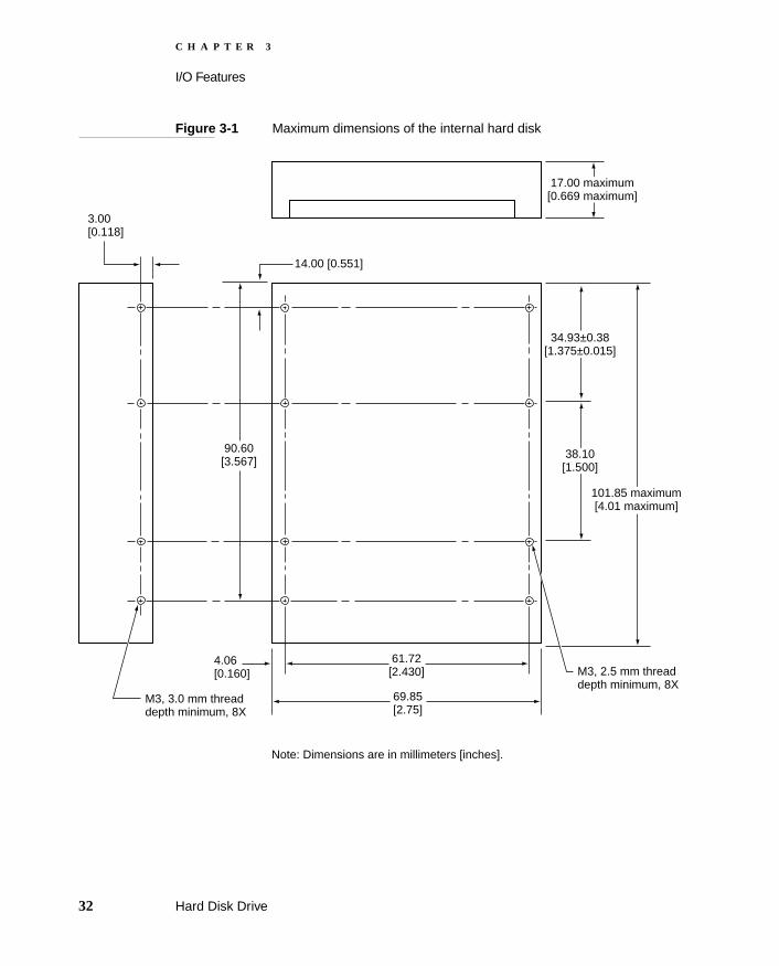
Figure 3-1 shows the maximum dimensions of the hard disk and the location of the mounting holes.
The minimum clearance between any conductive components on the drive and the bottom of the mounting envelope is 0.5 mm.
Hard Disk Drive 31
C H A P T E R 3
I/O Features
Figure 3-1 Maximum dimensions of the internal hard disk
3.00[0.118]
4.06[0.160]
61.72[2.430]
69.85[2.75]
M3, 2.5 mm threaddepth minimum, 8X
Note: Dimensions are in millimeters [inches].
17.00 maximum[0.669 maximum]
101.85 maximum[4.01 maximum]
38.10[1.500]
90.60[3.567]
14.00 [0.551]
34.93±0.38[1.375±0.015]
M3, 3.0 mm threaddepth minimum, 8X
32 Hard Disk Drive

C H A P T E R 3
I/O Features
Hard Disk Connector 3
The internal hard disk has a 48-pin connector that carries both the ATA signals and the power for the drive. The connector has the dimensions of a 50-pin connector, but with one row of pins removed, as shown in Figure 3-2. The remaining pins are in two groups: pins 1–44, which carry the signals and power, and pins 46–48, which are reserved. Pin 20 has been removed, and pin 1 is located nearest the gap, rather than at the end of the connector.
Figure 3-2 Hard disk connector and location
Note: Dimensions are in millimeters [inches].
17.00 maximum[0.669 maximum]
3.99[0.157]
10.14±0.375[0.399±0.014]
Key: vacantposition at pin 20
Vacant row in50-pin connector
Pin 1
Center line of pin 44
10.24[0.403]
14.00[0.551]
Hard Disk Drive 33

C H A P T E R 3
I/O Features
Signal Assignments 3
Table 3-1 shows the signal assignments on the 44-pin portion of the hard disk connector. A slash (/) at the beginning of a signal name indicates an active-low signal.
Table 3-1 Pin assignments on the ATA hard disk connector
Pin number Signal name
Pin number Signal name
1 /RESET 2 GROUND
3 DD7 4 DD8
5 DD6 6 DD9
7 DD5 8 DD10
9 DD4 10 DD11
11 DD3 12 DD12
13 DD2 14 DD13
15 DD1 16 DD14
17 DD0 18 DD15
19 GROUND 20 KEY
21 DMARQ 22 GROUND
23 /DIOW 24 GROUND
25 /DIOR 26 GROUND
27 IORDY 28 CSEL
29 /DMACK 30 GROUND
31 INTRQ 32 /IOCS16
33 DA1 34 /PDIAG
35 DA0 36 DA2
37 /CS0 38 /CS1
39 /DASP 40 GROUND
34 Hard Disk Drive

C H A P T E R 3
I/O Features
ATA Signal Descriptions 3
Table 3-2 describes the signals on the ATA hard disk connector.
41 +5V LOGIC 42 +5V LOGIC
43 GROUND 44 Reserved
NOTE CSEL, /DASP, /IOCS16, and /PDIAG are not used; see Table 3-2
Table 3-2 Signals on the ATA hard disk connector
Signal name Signal description
DA(0–2) Device address; used by the computer to select one of the registers in the ATA drive. For more information, see the descriptions of the CS0 and CS1 signals.
DD(0–15) Data bus; buffered from IOD(16–31) of the computer’s I/O bus. DD(0–15) are used to transfer 16-bit data to and from the drive buffer. DD(8–15) are used to transfer data to and from the internal registers of the drive, with DD(0–7) driven high when writing.
/CS0 Register select signal. It is asserted low to select the main task file registers. The task file registers indicate the command, the sector address, and the sector count.
/CS1 Register select signal. It is asserted low to select the additional control and status registers on the ATA drive.
CSEL Cable select; not available on this computer (n.c.).
/DASP Device active or slave present; not available on this computer (n.c.).
IORDY I/O ready; when driven low by the drive, signals the CPU to insert wait states into the I/O read or write cycles.
Table 3-1 Pin assignments on the ATA hard disk connector (continued)
Pin number Signal name
Pin number Signal name
Hard Disk Drive 35

C H A P T E R 3
I/O Features
The built-in ATA devices and ATA devices in the expansion bay are separately connected to the I/O bus through bidirectional bus buffers.
Trackpad 3
The pointing device in the Macintosh PowerBook G3 Series computers is a trackpad. The trackpad is a solid-state device that emulates a mouse by sensing the motions of the user’s finger over its surface and translating those motions into ADB commands.
A single button below the trackpad is used to make selections. Alternatively, the user can tap and double tap on the pad itself. As described in the user’s manual, the trackpad responds to one or two taps on the pad itself as one or
/IOCS16 I/O channel select; not used on this computer (pulled low by 1 kΩ).
/DIOR I/O data read strobe.
/DIOW I/O data write strobe.
/DMACK Used by the host to initiate a DMA transfer in response to DMARQ.
DMARQ Asserted by the device when it is ready to transfer data to or from the host.
INTRQ Interrupt request. This active high signal is used to inform the computer that a data transfer is requested or that a command has terminated.
/PDIAG Asserted by device 1 to indicate to device 0 that it has completed the power-on diagnostics; not available on this computer (n.c.).
/RESET Hardware reset to the drive; an active low signal.
Key This pin is the key for the connector.
Table 3-2 Signals on the ATA hard disk connector (continued)
Signal name Signal description
36 Trackpad

C H A P T E R 3
I/O Features
two clicks of the button. The user can tap and drag on the trackpad in much the same manner as clicking and dragging with the mouse.
Keyboard 3
On the Macintosh PowerBook G3 Series computers, the keyboard has a new layout with an embedded numeric keypad. The embedded keypad is activated by a new function key that is located in the lower left corner of the keyboard.
To activate the embedded numeric keypad, the user holds down the function key and presses the F5 (num lock) key. The num lock LED comes on to indicate that the numeric keypad is active. In that mode of operation, only the numeric keypad, the modifier keys, and certain other special functions are active, as shown in Figure 3-3. While the keyboard is in the keypad mode, the user can type alphabetical information by holding down the function key.
In addition to the embedded numeric keypad, the keypad mode gives several other keys special functions. Figure 3-3 highlights the keys that are functional when the keypad mode is active. To see the effects of the keypad mode on individual keys, the user can use the Key Caps item in the Apple menu.
The Macintosh PowerBook G3 Series computers use a new key combination for forcing a reset and power off. The user holds down the shift, function, and control keys and presses the power key. This key combination also forces a reset of the parameter RAM, so it should be used only as a last resort. To force a reset without turning off the power, the user holds down the control and command keys and presses the power key.
The keyboard is removable to allow access to the internal components and expansion connectors inside the computer. The keyboard is held in place by two catches that are accessible through the expansion bay openings. After removing the modules from the expansion bays, the user can insert a finger into each bay and release the catches.
Keyboard 37

C H A P T E R 3
I/O Features
Figure 3-3 Keyboard and embedded keypad
F5
fn
return
^6
&7
*8
(9
)0 -
-
U I O P
J K L ;
M . / ?>
:
F9 F10 F11F5 F7 F8num lock
clear 7 8 9
4 5 6
1
0
2 3 enter
pg up
pg dn sndhome
-
+.
*
/ =
insert delete prt screen scr lock pause
num lock insert delete prt screen scr lock pause
clear 7 8 9 / =
4 5 6 *
enter1 2 3 -
0 . +
pg up
home pg dn snd
]
return
shift
~
`
!1
@2
#3
$4
%5
^6
&7
*8
(9
)0 -
- +=
esc F2 F3 F4F1
Q W E R T Y U I O P [
A S D F G H J K L ; '
Z X C V B N M , . /
?><
":
delete
\tab
caps lock
shift
F9 F10 F11 F12F6 F7 F8
ctrl option option
alt
|
enter
alt
]
shift
+=
T Y [
G H '
V B N ,
<
"
delete
\
F12F6
option
alt
|
enter
38 Keyboard

C H A P T E R 3
I/O Features
Flat Panel Display 3
The Macintosh PowerBook G3 Series computers have built-in color flat panel displays that are backlit by a cold cathode fluorescent lamps (CCFL). Three sizes of displays are available.
The Macintosh PowerBook G3 Series includes models with three different sizes of displays: 12.1, 13.3, and 14.1 inches, measured diagonally. The 12.1-inch display contains 800 by 600 pixels and can show up to thousands of colors. The display technology used for the 12.1-inch display is STN (supertwist nematic). The 13.3- and 14.1-inch displays contain 1024 by 768 pixels and can show up to millions of colors. Those displays use TFT (thin-film transistor) technology for high contrast and fast response. Table 3-3 lists the display resolution and display technology for each size of display.
External Video Connectors 3
The Macintosh PowerBook G3 Series computers have a built-in connector for an external VGA or SVGA monitor. An optional adapter allows the user to attach a standard Apple video cable. The 13.3- and 14.1-inch models also have an S-video connector that supplies a video signal for an NTSC or PAL video monitor or VCR. The connectors and adapter are described in the sections
Table 3-3 Types of displays
Display size Display resolutionDisplay technology
Maximum number of colors
12.1 inches 800 by 600 (SVGA) STN Thousands
13.3 inches 1024 by 768 (XGA) TFT Millions
14.1 inches 1024 by 768 (XGA) TFT Millions
Flat Panel Display 39

C H A P T E R 3
I/O Features
Monitors Supported 3
With the adapter, the Macintosh PowerBook G3 Series computers can display on any Apple monitor, including the AV monitors and the 17-inch and 20-inch multiple scan monitors. The computers also support VGA and SVGA monitors and PAL and NTSC television monitors, as shown in Table 3-4 and Table 3-5.
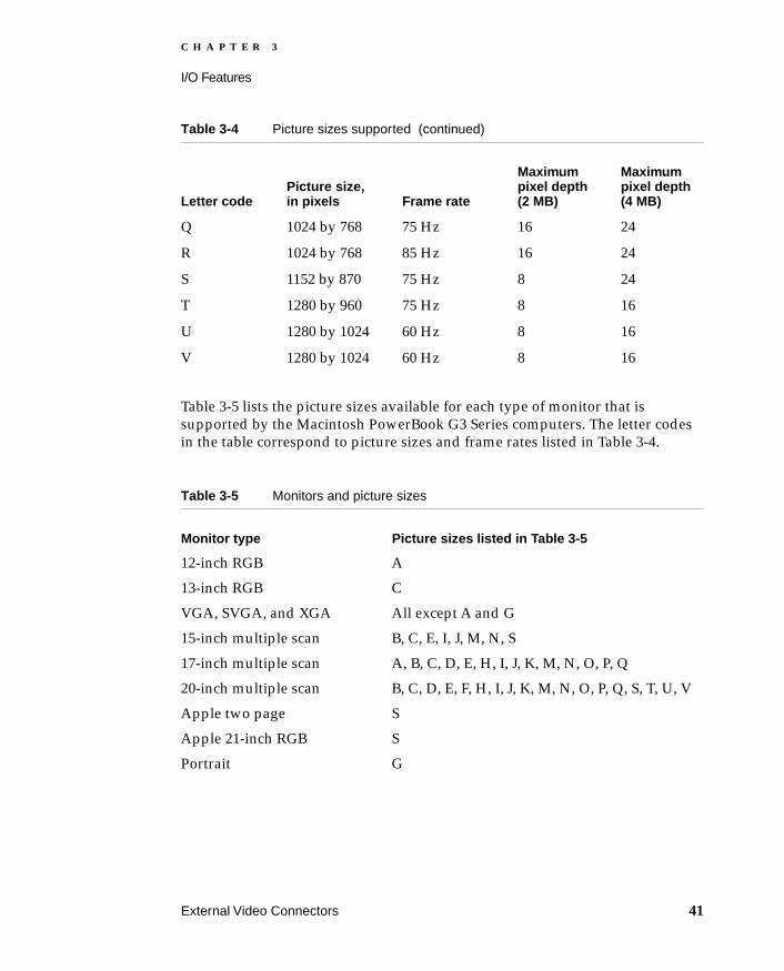
The Macintosh PowerBook G3 Series computers include either 2 or 4 MB of SGRAM. Table 3-4 lists the pixel depths supported with either 2 MB or 4 MB of SGRAM for each picture size available. The letter codes are used to identify the picture sizes supported by the monitors listed in Table 3-5.
Table 3-4 Picture sizes supported
Letter codePicture size, in pixels Frame rate
Maximum pixel depth (2 MB)
Maximum pixel depth (4 MB)
A 512 by 384 60 Hz 24 24
B 640 by 480 60 Hz 24 24
C 640 by 480* 67 Hz 24 24
D 640 by 480* 72 Hz 24 24
E 640 by 480* 75 Hz 24 24
F 640 by 480* 85 Hz 24 24
G 640 by 870 75 Hz 16 24
H 800 by 600 56 Hz 16 24
I 800 by 600 60 Hz 16 24
J 800 by 600 72 Hz 16 24
K 800 by 600 75 Hz 16 24
L 800 by 600 85 Hz 16 24
M 832 by 624 75 Hz 16 24
N 1024 by 768 60 Hz 16 24
O 1024 by 768 70 Hz 16 24
P 1024 by 768 72 Hz 16 24
40 External Video Connectors
C H A P T E R 3
I/O Features
Table 3-5 lists the picture sizes available for each type of monitor that is supported by the Macintosh PowerBook G3 Series computers. The letter codes in the table correspond to picture sizes and frame rates listed in Table 3-4.
Q 1024 by 768 75 Hz 16 24
R 1024 by 768 85 Hz 16 24
S 1152 by 870 75 Hz 8 24
T 1280 by 960 75 Hz 8 16
U 1280 by 1024 60 Hz 8 16
V 1280 by 1024 60 Hz 8 16
Table 3-5 Monitors and picture sizes
Monitor type Picture sizes listed in Table 3-5
12-inch RGB A
13-inch RGB C
VGA, SVGA, and XGA All except A and G
15-inch multiple scan B, C, E, I, J, M, N, S
17-inch multiple scan A, B, C, D, E, H, I, J, K, M, N, O, P, Q
20-inch multiple scan B, C, D, E, F, H, I, J, K, M, N, O, P, Q, S, T, U, V
Apple two page S
Apple 21-inch RGB S
Portrait G
Table 3-4 Picture sizes supported (continued)
Letter codePicture size, in pixels Frame rate
Maximum pixel depth (2 MB)
Maximum pixel depth (4 MB)
External Video Connectors 41
C H A P T E R 3
I/O Features
NoteThe Macintosh PowerBook G3 Series computers do not provide displays with 2 bits per pixel.
If the external monitor can display the same size picture as the computer, the computer can display simultaneously on both the external monitor and the flat panel display. This mode of display, called Simulscan, provides the same information on both displays. On the 13.3- and 14.1-inch models, Simulscan is available at 1024 x 768 pixels; on the 12.1-inch models, Simulscan is available at 800 x 600 pixels.
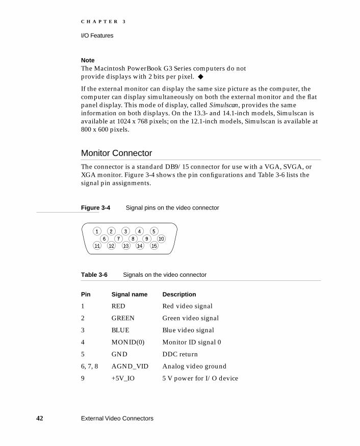
Monitor Connector 3
The connector is a standard DB9/15 connector for use with a VGA, SVGA, or XGA monitor. Figure 3-4 shows the pin configurations and Table 3-6 lists the signal pin assignments.
Figure 3-4 Signal pins on the video connector
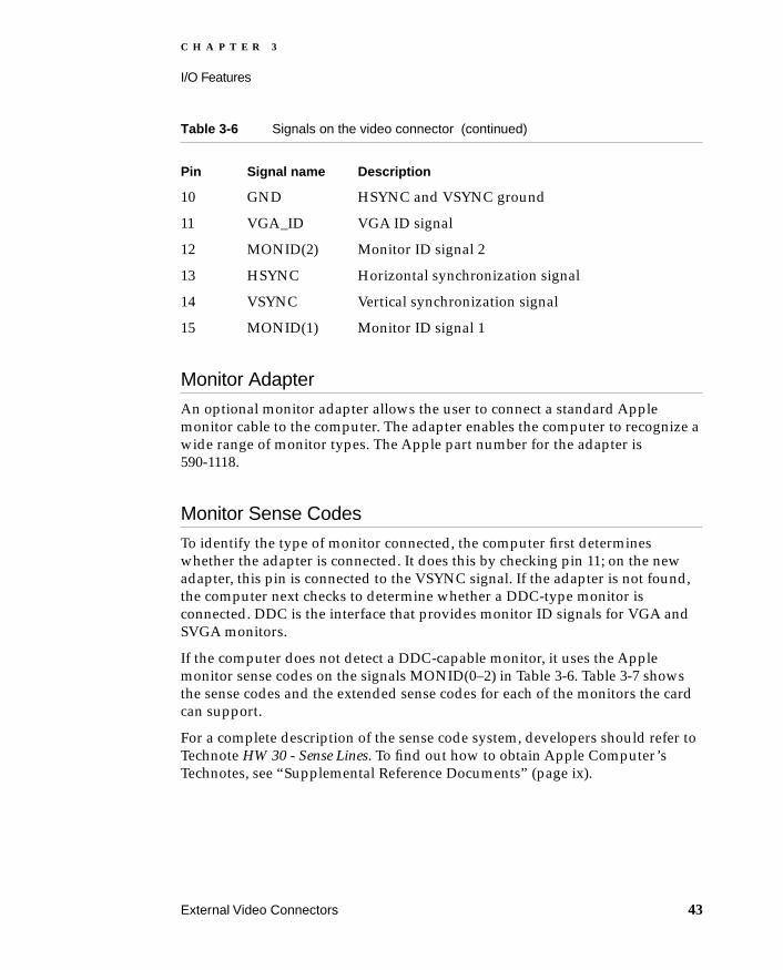
Table 3-6 Signals on the video connector
Pin Signal name Description
1 RED Red video signal
2 GREEN Green video signal
3 BLUE Blue video signal
4 MONID(0) Monitor ID signal 0
5 GND DDC return
6, 7, 8 AGND_VID Analog video ground
9 +5V_IO 5 V power for I/O device
1 2 3 4 56 7 8 9 10
11 12 13 14 15
42 External Video Connectors
C H A P T E R 3
I/O Features
Monitor Adapter 3
An optional monitor adapter allows the user to connect a standard Apple monitor cable to the computer. The adapter enables the computer to recognize a wide range of monitor types. The Apple part number for the adapter is 590-1118.
Monitor Sense Codes 3
To identify the type of monitor connected, the computer first determines whether the adapter is connected. It does this by checking pin 11; on the new adapter, this pin is connected to the VSYNC signal. If the adapter is not found, the computer next checks to determine whether a DDC-type monitor is connected. DDC is the interface that provides monitor ID signals for VGA and SVGA monitors.
If the computer does not detect a DDC-capable monitor, it uses the Apple monitor sense codes on the signals MONID(0–2) in Table 3-6. Table 3-7 shows the sense codes and the extended sense codes for each of the monitors the card can support.
For a complete description of the sense code system, developers should refer to Technote HW 30 - Sense Lines. To find out how to obtain Apple Computer’s Technotes, see “Supplemental Reference Documents” (page ix).
10 GND HSYNC and VSYNC ground
11 VGA_ID VGA ID signal
12 MONID(2) Monitor ID signal 2
13 HSYNC Horizontal synchronization signal
14 VSYNC Vertical synchronization signal
15 MONID(1) Monitor ID signal 1
Table 3-6 Signals on the video connector (continued)
Pin Signal name Description
External Video Connectors 43

C H A P T E R 3
I/O Features
Table 3-7 Monitor sense codes
Monitor typeStandard sense code Extended sense code
(S2–0) (S1,0) (S2,0) (S2,1)
Macintosh 21-inch Color Display 0 0 0 — — —
Macintosh Portrait Display 0 0 1 — — —
Macintosh 12-inch RGB Display 0 1 0 — — —
Apple Two-Page Monochrome Monitor 0 1 1 — — —
NTSC monitor 1 0 0 — — —
15-inch RGB monitor 1 0 1 — — —
Apple Multiple Scan 14 and 15 Displays 1 1 0 0 0 0 0 1 1
Apple Multiple Scan 17 and 1705 Displays 1 1 0 0 0 1 0 1 1
Apple Multiple Scan 20 Display 1 1 0 1 0 0 0 1 1
AppleVision 850, 850av, 1710, and 1710av Displays, Macintosh 12-inch Monochrome Display, or AppleColor High Resolution RGB Monitor
1 1 0 1 0 1 0 1 1
PAL monitor 1 1 1 0 0 0 0 0 0
NTSC monitor, with convolution 1 1 1 0 1 0 1 0 0
VGA or SVGA monitor 1 1 1 0 1 0 1 1 1
Macintosh 16-inch Color Display 1 1 1 1 0 1 1 0 1
PAL monitor, with convolution 1 1 1 1 1 0 0 0 0
19-inch RGB monitor 1 1 1 1 1 1 0 1 0
No monitor connected 1 1 1 1 1 1 1 1 1
44 External Video Connectors

C H A P T E R 3
I/O Features
NoteVGA, SVGA, and XGA monitors all have the same sense code. The first time the user starts up with an SVGA or XGA monitor, the video card treats it as a VGA monitor and shows a 640-by-480 pixel display. The user can switch to a larger display mode from the Monitors control panel; when that happens, the computer changes the display to the larger mode immediately and uses that mode the next time it is started up.
External Video Connector 3
The Macintosh PowerBook G3 Series computer have an S-video connector for composite video output to a PAL or NTSC video monitor or VCR. The video output connector is a 7-pin S-video connector. Figure 3-5 shows the arrangement of the pins and Table 3-8 shows the pin assignments on the S-video connector.
Figure 3-5 S-video connector
1
4 7
2 56
3
External Video Connectors 45

C H A P T E R 3
I/O Features
An adapter is available that can be plugged into the S-video connector and accepts an RCA plug from a composite video monitor.
The Macintosh PowerBook G3 Series computers provide composite video output at picture sizes and frame rates compatible with the NTSC and PAL standards; the picture sizes are listed in Table 3-9. Those picture resolutions produce underscanned displays on standard monitors.
Table 3-8 Pin assignments for the S-video output connector
Pinnumber S-video output connector
1 Analog GND
2 Analog GND
3 Video Y (luminance)
4 Video C (chroma)
5 Composite video
6 Unused
7 Unused
Table 3-9 Picture sizes for composite video output
Picture sizePixel depth (2 MB SGRAM)
Pixel depth (4 MB SGRAM)
512 by 384 24 24
640 by 480 24 24
800 by 600 16 24
832 by 624 16 24
46 External Video Connectors
C H A P T E R 3
I/O Features
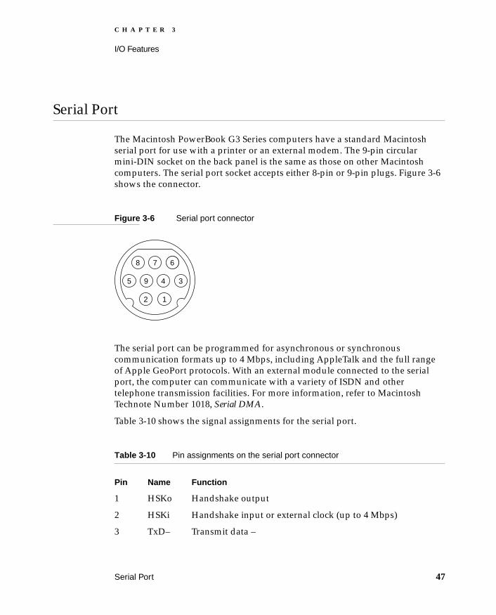
Serial Port 3
The Macintosh PowerBook G3 Series computers have a standard Macintosh serial port for use with a printer or an external modem. The 9-pin circular mini-DIN socket on the back panel is the same as those on other Macintosh computers. The serial port socket accepts either 8-pin or 9-pin plugs. Figure 3-6 shows the connector.
Figure 3-6 Serial port connector
The serial port can be programmed for asynchronous or synchronous communication formats up to 4 Mbps, including AppleTalk and the full range of Apple GeoPort protocols. With an external module connected to the serial port, the computer can communicate with a variety of ISDN and other telephone transmission facilities. For more information, refer to Macintosh Technote Number 1018, Serial DMA.
Table 3-10 shows the signal assignments for the serial port.
Table 3-10 Pin assignments on the serial port connector
Pin Name Function
1 HSKo Handshake output
2 HSKi Handshake input or external clock (up to 4 Mbps)
3 TxD– Transmit data –
8 7
1
5 4
2
39
6
Serial Port 47

C H A P T E R 3
I/O Features
SCSI Port 3
The SCSI port uses an HDI-30 connector and supports the SCSI interface as defined by the American National Standards Institute (ANSI) X3T9.2 committee.
The external HDI-30 connector is identical to those used in other PowerBook models. The data and control signals on the SCSI bus are active low signals that are driven by open drain outputs. The SCSI bus has built-in active termination.
Table 3-11 shows the signal assignments for the external SCSI connector. Pin 1 of the external SCSI connector is the /SCSI.DISK.MODE signal. When this signal is asserted at startup time, the computer operates in disk mode instead of starting up the Mac OS.
4 Gnd Ground
5 RxD– Receive data –
6 TxD+ Transmit data +
7 GPi General-purpose input (wake up CPU or perform DMA handshake)
8 RxD+ Receive data +
9 +5V Power to external device (300 mA maximum)
Table 3-11 SCSI connector signals
Pin Signal name Pin Signal name
1 /SCSI.DISK.MODE 16 /DB6
2 /DB0 17 GND
3 GND 18 /DB7
Table 3-10 Pin assignments on the serial port connector
Pin Name Function
48 SCSI Port

C H A P T E R 3
I/O Features
ADB Port 3
The Apple Desktop Bus (ADB) port on the Macintosh PowerBook G3 Series computers is functionally the same as on other Macintosh computers. The connector is located on the back of the computer.
Unlike earlier ADB-equipped computers, the Wall Street computers allow the user to unplug and replace ADB devices while the computer is operating.
The ADB connector is a 4-pin mini-DIN connector. Figure 3-7 shows the arrangement of the pins on the ADB connector.
4 /DB1 19 /DBP
5 TERMPWR (not used; reserved)
20 GND
6 /DB2 21 /REQ
7 /DB3 22 GND
8 GND 23 /BSY
9 /ACK 24 GND
10 GND 25 /ATN
11 /DB4 26 /C/D
12 GND 27 /RST
13 GND 28 /MSG
14 /DB5 29 /SEL
15 GND 30 /I/O
Table 3-11 SCSI connector signals (continued)
Pin Signal name Pin Signal name
ADB Port 49

C H A P T E R 3
I/O Features
Figure 3-7 ADB connector
The ADB is a single-master, multiple-slave serial communications bus that uses an asynchronous protocol and connects keyboards, graphics tablets, mouse devices, and other devices to the computer. The custom ADB microcontroller drives the bus and reads status from the selected external device. A 4-pin mini-DIN connector connects the ADB controller to the outside world. Table 3-12 lists the ADB connector pin assignments. For more information about the ADB, see Guide to the Macintosh Family Hardware, second edition.
IMPORTANT
The total current available for all devices connected to the +5-V pins on the ADB is 100 mA.
Table 3-12 ADB connector pin assignments
Pin number Name Description
1 ADB Bidirectional data bus used for input and output; an open collector signal pulled up to +5 volts through a 470-ohm resistor on the main logic board.
2 PSW Power-on signal; generates reset and interrupt key combinations.
3 +5V +5 volts from the computer.
4 GND Ground from the computer.
4 3
2 1
50 ADB Port

C H A P T E R 3
I/O Features
Infrared Communication Link 3
The computer has a directed infrared (IR) communication link connected internally to serial port B. When the computer is placed within range of another device with an IR interface, it can send and receive serial data using one of several communications protocols. The other device may be another IR-equipped PowerBook, a desktop computer with an IR communications link, or some other device that complies with the Infrared Data Association (IrDA) standard. The minimum range of the IR link is approximately 2 inches, and the maximum range is 34 inches for IrDA compliant devices and 6 feet for PowerBooks.
The IR link in the Macintosh PowerBook G3 Series computers supports the following communications methods:
IRTalk (LocalTalk over IR)
IrDA at up to 4.0 Mbps
For LocalTalk operation, the IR link takes serial bits from the SCC and transmits them using a modified form of pulse encoding called PPM-4. This method of encoding uses four cycles of a 3.92-MHz carrier for each pulse, which increases the system’s immunity to interference from ambient light sources. Two serial bits are encoded as a symbol consisting of a start pulse followed by either a second pulse in one of three possible positions or no second pulse.
The IrDA modulation method complies with the IrDA physical layer standard, which can be found at ftp://irda.org.
Sound System 3
The 16-bit stereo audio circuitry provides high-quality sound input and output through the built-in microphone and speakers. The user can also connect external input and output devices by way of the sound input and output jacks.
The sound system is based on the Screamer codec IC along with input and output amplifiers and signal conditioners. In the Macintosh PowerBook G3 Series computers, the Screamer codec supports three channels of digital sound:
Infrared Communication Link 51

C H A P T E R 3
I/O Features
two stereo channels plus a multiplexed channel. The sound system supports sample sizes up to 16 bits and sample rates of 11.025 kHz, 22.05 kHz, and 44.1 kHz.
The frequency response of the sound circuits, not including the microphone and speakers, is within plus or minus 2 dB from 20 Hz to 20 kHz. Total harmonic distortion and noise is less than 0.05 percent with a 1-V rms sine wave input. The signal-to-noise ratio (SNR) is 85 dB, with no audible discrete tones.
NoteAll sound level specifications in this section are rms values.
Sound Inputs 3
The sound system accepts inputs from six possible sources:
built-in microphone
external stereo sound input jack
1-bit sound from the CardBus sockets
sound from the communication (modem) slot
sound from the expansion bays
sound from a Zoomed Video device in the lower CardBus socket
The microphone and the sound input jack have dedicated input channels on the Screamer IC; the sound input from the PC Card slot has its own input, and the other three inputs share an input on the IC. Those three inputs are switched on and off by the hardware; they can be selected one at a time for play-through or recording.
Built-in Microphone 3
The sound signal from the built-in microphone goes through a dedicated preamplifier that raises its nominal 30-mV level to the 0.6-V level of the codec circuits in the Screamer IC.
52 Sound System

C H A P T E R 3
I/O Features
External Sound Input 3
The external sound input jack is located on the back of the computer near the left corner.The sound input jack accepts line-level stereo signals or an Apple PlainTalk microphone. When a connector is plugged into the external sound input jack, the computer turns off the sound input from the built-in microphone. The input jack has the following electrical characteristics:
input impedance: 6.8k
maximum level: 2.0 V rms
NoteThe sound input jack accepts the maximum sound output of an audio CD without clipping. When working with sound sources that have significantly lower levels, you may wish to increase the signal gain of the sound input circuit. You can do that using the Sound Manager as described in Inside Macintosh: Sound.
Expansion Bay Sound Input 3
The sound inputs from the expansion bays have the following electrical characteristics:
input impedance: 3.2k
maximum level: 0.5 V rms
CardBus Sound Input 3
Each CardBus socket has one sound output pin (SPKR_OUT) and the computer accepts either one or two cards. The one-bit digital signals from the sound output pins are exclusive-ORed together and routed to the Screamer IC, which sends them to the built-in speaker and the external sound output jack.
Sound Outputs 3
The sound system sends computer-generated sounds or sounds from an expansion-bay device or CardBus card to the built-in speakers, the communication slot, and the external sound output jack.
Sound System 53

C H A P T E R 3
I/O Features
External Sound Output 3
The sound output jack is located on the back of the computer at the left corner. The sound output jack provides enough current to drive a pair of low-impedance headphones. The sound output jack has the following electrical characteristics:
output impedance: 33 Ω
minimum recommended load impedance: 32 Ω
maximum level: 1 V rms
maximum current: 32 mA peak
Internal Speakers 3
The computer has two internal speakers. The computer turns off the sound signals to the internal speakers when an external device is connected to the sound output jack and during power cycling.
Communication Slot 3
Sound output signals are provided for the internal communications slot. The sound signals are at an audio level of 0.5V RMS.
Ethernet Port 3
Macintosh PowerBook G3 Series computers have a built-in Ethernet port. The Ethernet port provides a 10 Mbps Ethernet interface with a 10BaseT connection.
The Ethernet interface conforms to the ISO/IEC 8802-3 specification, where applicable.
54 Ethernet Port

C H A P T E R 3
I/O Features
Internal Modem 3
Some configurations of the Macintosh PowerBook G3 Series computers come with a modem card installed in the internal communication slot. The modem card has an RJ-45 connector that is accessible through an opening in the left side of the computer’s case.
The modem card has the following features:
K56flex technology
modem bit rates up to 56 Kbps
fax modem bit rates up to 14.4 Kbps
Facsimile applications must support Class 1 fax; a Class 1 fax application comes with the computer.
The modem appears to the system as a serial port that responds to the typical AT commands. The modem card provides a sound output for monitoring the progress of the modem connection.
Internal Modem 55


C H A P T E R 4
Figure 4-0Listing 4-0Table 4-0
Expansion Features 4
57

C H A P T E R 4
Expansion Features
This chapter consists of three sections, each of which describes one of the expansion features of the Macintosh PowerBook G3 Series computers:
“Expansion Bays”
“RAM Expansion Slots”
“CardBus Slot”
Expansion Bays 4
The expansion bays are openings on the right and left sides of the computer that accept expansion modules containing either power devices or storage devices. Either expansion bay can accommodate a battery, a floppy-disk drive, or some other 3.5-inch storage device.The expansion bay on the right side can also accommodate a 5.25-inch device such as a CD-ROM drive or a DVD-ROM drive.
The expansion bays are similar in that both have battery connectors and both support IDE devices such as a 3.5-inch floppy disk drive. In the 13.3- and 14.1-inch models, the expansion bay on the right side supports PCI-based devices as well as IDE devices, though not at the same time. Table 4-1 lists the types of devices supported by each expansion bay.
Table 4-1 Devices supported by the expansion bays
Left Expansion Bay Right Expansion Bay
Battery Battery
Floppy-disk drive Floppy-disk drive
IDE drive up to 3.5 inches IDE drive up to 5.25 inches
PCI device up to 5.25 inches (only on 13.3- and 14.1-inch models)
58 Expansion Bays

C H A P T E R 4
Expansion Features
Mechanical Design of Expansion Bay Modules 4
The primary dimensions of an expansion bay module for the Macintosh PowerBook G3 Series computers are:
Width: 106 mm; 128 mm extension in right bay only
Length: 140 mm
Thickness: 17 mm
Batteries may exceed the 17 mm thickness specification by as much as 3 mm, but only on the top and only away from the edges, which must not exceed 17 mm in thickness.
To accommodate 5.25-inch devices, a module with a 5.25-inch device can extend an additional 22 mm toward the back of the computer when the module is installed in the right expansion bay. Even with the 22 mm extension, the bottom of the module is still only 106 mm wide; the added width does not extend all the way to the bottom of the module. The extension forms a sort of shelf on one side of the module.
The right expansion bay has a hinged door that covers the extension part of the opening when a battery or other 3.5-inch device is installed.
Each expansion module has a notch on the side for the latching mechanism, which is on the front of the computer. Expansion modules that can be installed in either bay must have the notch on both sides. Modules that can only be installed in the right bay have the notch only on the side that faces the front of the computer when the module is installed.
To request manufacturing specifications for the expansion bay module, send email to [email protected].
Expansion Bay Connectors 4
Each expansion bay has two connectors: a five-contact connector for batteries and a 90-pin connector for data devices. This section describes only the 90-pin data connector.
The connector in the left expansion bay is mechanically the same as the one in the right expansion bay, but electrically it provides only IDE support and does not support the PCI bus.
Even though the connectors are the same as those in the expansion bay in the PowerBook 3400 computer, expansion modules for that computer will not work
Expansion Bays 59

C H A P T E R 4
Expansion Features
in a Macintosh PowerBook G3 Series computer. The expansion-bay connector pins marked ADAPTER_PWR in the Macintosh PowerBook G3 Series computers are similar to the pins marked RAW_BAT on the PowerBook 3400 computer. Their function is the same: to accept power input from a power adapter.
The expansion bay connector is a 90-pin shielded connector with two rows of pins. The rows of pins are divided into two groups by a gap that occurs between pins 11 and 12 in one row and between pins 56 and 57 in the other row.
The connector used on the expansion modules is AMP part number 787481-1. For a specification sheet or information about obtaining this connector, contact AMP at
AMP, Inc.
19200 Stevens Creek Blvd.
Cupertino, CA 95014-2578
408-725-4914
Figure 4-1 (page 61) shows a section through the expansion bay connector and gives its dimensions.
60 Expansion Bays

C H A P T E R 4
Expansion Features
Figure 4-1 Section through expansion bay connector
IMPORTANT
The expansion bay connectors are designed so that when a module is inserted into either expansion bay, the first connection is the ground by way of the connector shells, then the power pins make contact, and last of all the signal lines.
Either expansion bay connector can be used for different kinds of devices. The values of the device ID signals DEV_ID(2–0) determine how the other signals are connected, as shown in Table 4-2 (page 62). A value of 0 corresponds to a device ID line connected to ground; a value of 1 corresponds to an open line.
IMPORTANT
An expansion bay module must never tie or pull up any device ID line to any power main.
6.45 [0.254]Contacts
5.00 [1.97]
9.45 [0.372]
14.65 [0.577]
3.50 [0.138]
Note: Dimensions are in millimeters [inches].
Expansion Bays 61

C H A P T E R 4
Expansion Features
ATA and Floppy Disk Signals on the Expansion Bay Connector 4
Table 4-3 shows the signal assignments on the left expansion bay connector and on the right expansion bay connector when it is used with an ATA device or a floppy disk drive. Signal names that begin with a slash (/) are active low.
NoteThe table shows the signals in the same arrangement as the pins on the connector; that is, with pin 1 next to pin 46 and pin 45 next to pin 90.
Table 4-2 Device ID signals and types of devices
DEV_ID(2) DEV_ID(1) DEV_ID(0) Type of device
0 0 0 MFM/GCR floppy disk, auto eject
0 0 1 Reserved
0 1 0 Reserved
0 1 1 ATA device; if the device supports DMA operation, DEV_ID(1) and DEV_ID(0) are connected together
1 0 0 Reserved
1 0 1 PCI device
1 1 0 Power input device
1 1 1 No device installed
Table 4-3 ATA and floppy disk signals on the expansion bay connector
Pin Direction Signal name Pin Direction Signal name
1 – n.c. 46 – n.c.
2 – n.c. 47 – n.c.
3 A3.3V 48 I SND_IN_L
4 I SND_IN_RET 49 I SND_IN_R
continued
62 Expansion Bays

C H A P T E R 4
Expansion Features
5 R Reserved 50 R Reserved
6 R Reserved 51 R ADAPTER_PWR
7 GND 52 R ADAPTER_PWR
8 R Reserved 53 – n.c.
9 I /DEV_IN 54 I/O DEV_ID(0)
10 I/O DEV_ID(1) 55 I/O DEV_ID(2)
11 GND 56 Reserved
— — (Gap) — — (Gap)
12 +5V 57 – n.c.
13 O /WRREQ 58 GND
14 O PHASE(0) 59 O PHASE(1)
15 +5V 60 O PHASE(2)
16 O PHASE(3) 61 LONG GND
17 O WRDATA 62 +5V
18 I RDDATA 63 O /FL_ENABLE
19 O HDSEL 64 O /IDE_RST
20 GND 65 – Reserved
21 – Reserved 66 – Reserved
22 – Reserved 67 +5V
23 – Reserved 68 – Reserved
24 I IOCHRDY 69 I/O IDE_D(0)
25 GND 70 I/O IDE_D(1)
26 I/O IDE_D(2) 71 I/O IDE_D(3)
27 +3V 72 I/O IDE_D(4)
continued
Table 4-3 ATA and floppy disk signals on the expansion bay connector (continued)
Pin Direction Signal name Pin Direction Signal name
Expansion Bays 63

C H A P T E R 4
Expansion Features
ATA and Floppy Disk Signal Definitions 4
The signals on the expansion bay connector are of three types: expansion bay audio and control signals, floppy disk signals, and ATA signals. The next three tables describe the three types of signals: Table 4-4 (page 65) describes the audio and control signals, Table 4-5 (page 65) describes the floppy disk signals, and Table 4-6 (page 66) describes the ATA signals.
28 I/O IDE_D(5) 73 I/O IDE_D(6)
29 I/O IDE_D(7) 74 GND
30 I/O IDE_D(8) 75 I/O IDE_D(9)
31 I/O IDE_D(10) 76 I/O IDE_D(11)
32 +3V 77 I/O IDE_D(12)
33 I/O IDE_D(13) 78 I/O IDE_D(14)
34 I/O IDE_D(15) 79 GND
35 O /DIOR 80 O /DIOW
36 O /CS3FX 81 O /CS1FX
37 +3V 82 O IDE_ADDR(0)
38 O IDE_ADDR(1) 83 O IDE_ADDR(2)
39 O /DMACK 84 GND
40 I DMARQ 85 I IDE_INTRQ
41 Reserved 86 Reserved
42 +3V 87 Reserved
43 Reserved 88 Reserved
44 Reserved 89 GND
45 ADAPTER_PWR 90 ADAPTER_PWR
Table 4-3 ATA and floppy disk signals on the expansion bay connector (continued)
Pin Direction Signal name Pin Direction Signal name
64 Expansion Bays

C H A P T E R 4
Expansion Features
Table 4-4 Audio and control signals on the expansion bay connector
Signal name Signal description
DEV_ID(0–2) These three signal lines identify the type of expansion bay device. Table 4-2 (page 62) shows the identification codes for different devices.
/DEV_IN This signal should be low whenever a device is installed in the expansion bay; it is used by the Heathrow IC to determine when a device has been inserted or removed. The expansion bay module should connect this pin to ground.
/IDE_RST/BUF_PCI_RST
Reset signals.
Table 4-5 Floppy disk signals on the expansion bay connector
Signal name Signal description
FD_RD Read data from the floppy disk drive.
/FL_ENABLE Floppy disk drive enable.
PHASE(0–3) Phase(0–2) are state-control lines to the drive; Phase(3) is the strobe signal for writing to the drive’s control registers.
WRDATA Write data to the floppy disk drive.
/WRREQ Write data request signal.
Expansion Bays 65

C H A P T E R 4
Expansion Features
NoteSignal names that begin with a slash (/) are active low.
Table 4-6 ATA signals on the expansion bay connector
Signal name Signal description
/CS1FX Register select signal. It is asserted low to select the main task file registers. The task file registers indicate the command, the sector address, and the sector count.
/CS3FX Register select signal. It is asserted low to select the additional control and status registers on the IDE drive.
/DIOR I/O data read strobe.
/DIOW I/O data write strobe.
DMARQ DMA request signal.
DMACK DMA acknowledge signal.
IDE_ADDR(0–2) IDE device address; used by the computer to select one of the registers in the drive. For more information, see the descriptions of the /CS1FX and /CS3FX signals.
IDE_D(0–15) IDE data bus, buffered from IOD(16–31) of the controller IC. IDE_D(0–15) are used to transfer 16-bit data to and from the drive buffer. IDE_D(0–7) are used to transfer data to and from the drive’s internal registers, with IDE_D(8-15) driven high when writing.
IOCHRDY I/O channel ready; when driven low by the IDE drive, signals the CPU to insert wait states into the I/O read or write cycles.
IDE_INTRQ IDE interrupt request. This active high signal is used to inform the computer that a data transfer is requested or that a command has terminated.
/MB_IDE_RST Hardware reset to the IDE drive.
66 Expansion Bays

C H A P T E R 4
Expansion Features
Unused IDE Signals on the Expansion Bay Connector 4
Several signals defined in the standard interface for the IDE drive are not used by the expansion bay. Those signals are listed in Table 4-7 along with any action required for the device to operate in the expansion bay.
Power on the Expansion Bay Connector 4
Table 4-8 describes the power lines on the expansion bay connector. The MB_+5V and MB_+3V lines are controlled by the /MB_PWR signal from the Heathrow IC.
IMPORTANT
The maximum combined total power available from the MB_+5V and MB_+3V lines is 5 W.
Table 4-7 Unused IDE signals on the expansion bay connector
Signal name Comment
CSEL This signal must be tied to ground to configure the device as the master in the default mode.
IOCS16 No action required.
PDIAG No action required; the device is never operated in master-slave mode.
DAS No action required.
Table 4-8 Power lines on the expansion bay connector
Signal name Signal description
GND Ground.
MB_+5V 5 V power; maximum total current is 1.0 A.
MB_+3V 3 V power; maximum total current is 1.5 A.
ADAPTER_PWR Power input from a power adapter.
Expansion Bays 67

C H A P T E R 4
Expansion Features
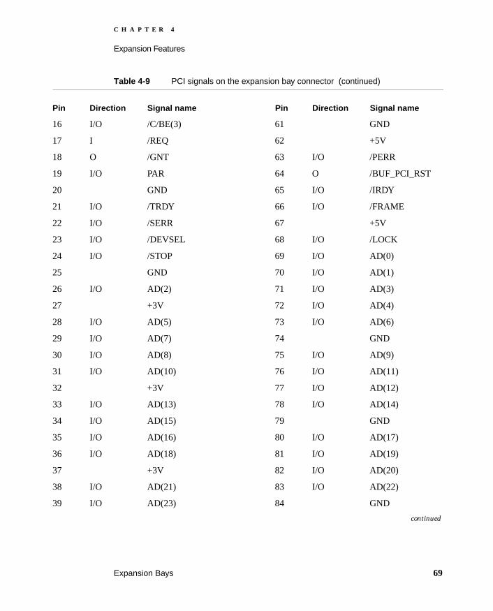
PCI Signals on the Right Expansion Bay Connector 4
Table 4-9 (page 68) shows the signal assignments on the right expansion bay connector when it is used with a PCI device. Signal names that begin with a slash (/) are active low.
NoteThe table shows the signals in the same arrangement as the pins on the connector; that is, with pin 1 next to pin 46 and pin 45 next to pin 90.
Table 4-9 PCI signals on the expansion bay connector
Pin Direction Signal name Pin Direction Signal name
1 n.c. 46 n.c.
2 n.c. 47 n.c.
3 A3.3V 48 I SND_IN_L
4 I SND_IN_RET 49 I SND_IN_R
5 R Reserved 50 R Reserved
6 R Reserved 51 O ADAPTER_PWR
7 GND 52 O ADAPTER_PWR
8 O MB_PCI_IDSEL 53 n.c.
9 I /DEV_IN 54 I/O DEV_ID(0)
10 I/O DEV_ID(1) 55 I/O DEV_ID(2)
11 GND 56 O PCI_CLK
— — (Gap) — — (Gap)
12 +5V 57 n.c.
13 I /INTA 58 GND
14 I/O /C/BE(0) 59 I/O /C/BE(1)
15 +5V 60 I/O /C/BE(2)
continued
68 Expansion Bays
C H A P T E R 4
Expansion Features
16 I/O /C/BE(3) 61 GND
17 I /REQ 62 +5V
18 O /GNT 63 I/O /PERR
19 I/O PAR 64 O /BUF_PCI_RST
20 GND 65 I/O /IRDY
21 I/O /TRDY 66 I/O /FRAME
22 I/O /SERR 67 +5V
23 I/O /DEVSEL 68 I/O /LOCK
24 I/O /STOP 69 I/O AD(0)
25 GND 70 I/O AD(1)
26 I/O AD(2) 71 I/O AD(3)
27 +3V 72 I/O AD(4)
28 I/O AD(5) 73 I/O AD(6)
29 I/O AD(7) 74 GND
30 I/O AD(8) 75 I/O AD(9)
31 I/O AD(10) 76 I/O AD(11)
32 +3V 77 I/O AD(12)
33 I/O AD(13) 78 I/O AD(14)
34 I/O AD(15) 79 GND
35 I/O AD(16) 80 I/O AD(17)
36 I/O AD(18) 81 I/O AD(19)
37 +3V 82 I/O AD(20)
38 I/O AD(21) 83 I/O AD(22)
39 I/O AD(23) 84 GND
continued
Table 4-9 PCI signals on the expansion bay connector (continued)
Pin Direction Signal name Pin Direction Signal name
Expansion Bays 69

C H A P T E R 4
Expansion Features
PCI Control Signals in Sleep Mode 4
The following PCI control signals are disconnected from the expansion bay during sleep: /DEVSEL, /FRAME, /GRANT, /INT, /IRDY, /LOCK, /PERR, /REQ, /SERR, /STOP, and /TRDY. PCI devices on a module in the expansion bay should have these signals pulled up through 100 KΩ resistors to the PCI device Vcc.
Figure 4-2 (page 71) shows the timing of the control signals on the expansion bay connector as the computer goes into and emerges from sleep mode.
40 I/O AD(24) 85 I/O AD(25)
41 I/O AD(26) 86 I/O AD(27)
42 +3V 87 I/O AD(28)
43 I/O AD(29) 88 I/O AD(30)
44 I/O AD(31) 89 GND
45 ADAPTER_PWR 90 ADAPTER_PWR
Table 4-9 PCI signals on the expansion bay connector (continued)
Pin Direction Signal name Pin Direction Signal name
70 Expansion Bays

C H A P T E R 4
Expansion Features
Figure 4-2 Timing of expansion bay control signals for sleep mode
PCI Signals During Power On and Off 4
Figure 4-3 (page 72) shows the timing of the control signals on the expansion module during the power-on sequence. Figure 4-4 (page 72) shows the timing of the control signals on the expansion module during the power-off sequence.
/CFW
SLEEP
PCICLK
t1 2t 3t
= 16 ms min. /CFW to clocks stopped
= 16 ms min. Clocks stopped to system sleep
= 50 ms min. Clocks started to clock valid
t1
2t
3t
Hi-Z Hi-Z
*/DEVSEL, /FRAME, /GRANT, /INT, /IRDY, /LOCK, /PERR, /REQ, /SERR, /STOP, and /TRDY
AD, C/BE,and controls*
/BUF_PCI_RST
Expansion Bays 71

C H A P T E R 4
Expansion Features
Figure 4-3 Timing of the expansion bay control signals during power on
Figure 4-4 Timing of the expansion bay control signals during power off
Hi-Z
/DEV_IN
/MB_PWREN
+3 V, +5 V
/BUF_PCI_RST and /IDE_RST
= 250 ms min.
= 5 ms min.
= 10 ms min.
t 1
2t
3t
*/DEVSEL, /FRAME, /GRANT, /INT, /IRDY, /LOCK, /PERR, /REQ, /SERR, /STOP, and /TRDY
AD, C/BE, and controls*
t1 2t 3t
/DEV_IN
/MB_PWREN
+3 V, +5 V
/BUF_PCI_RST and /IDE_RST
Hi-Z AD, C/BE, and controls*
*/DEVSEL, /FRAME, /GRANT, /INT, /IRDY, /LOCK, /PERR, /REQ, /SERR, /STOP, and /TRDY
72 Expansion Bays
C H A P T E R 4
Expansion Features
Power Sequences 4
Here are the sequences of events on the power supply and PCI control signals when the operating mode of the computer changes. Knowledge of these sequences will help developers design devices that operate properly when the computer switches from one power mode to another.
Power Sequence From Off to On 4
Here is the sequence of states and events when the computer switches from off to on:
1. The computer is in the power-off mode.
2. The PMU detects power on.
3. The main power supplies (+5V, +3.3V, and +2.6V) switch on.
4. The clocks begin operating.
5. The /CFW signal changes to high (inactive).
6. The /RESET signal changes to high (inactive).
7. The processor starts executing the ROM code.
8. If a module is installed in the expansion bay, power to the expansion bay switches on and the port is opened.
9. The computer loads and launches the operating system from the available mass storage device.
10. The computer is in the on (normal operating) mode.
Power Sequence From On to Sleep 4
Here is the sequence of states and events when the computer switches from on to sleep:
1. The computer is in the on (normal operating) mode.
2. The SLEEP mode is initiated by the user or by some predetermined condition.
3. The processor stops running.
4. The /CFW signal changes to low (active).
5. There is a time delay of 16 ms.
Expansion Bays 73

C H A P T E R 4
Expansion Features
6. The clocks stop operating.
7. The SLEEP signal switches to high (active), which switches off the power to unused circuitry.
8. If a PCI device is installed in the expansion bay, power to the expansion bay remains on.
9. If the expansion bay does not have a PCI device installed in it, power to the expansion bay switches off and the port is closed.
10. The computer is in sleep mode.
Power Sequence From Sleep to On 4
Here is the sequence of states and events when the computer switches from sleep to on:
1. The computer is in sleep mode.
2. The PMU detects keyboard activity or the power-on switch.
3. The SLEEP signal changes to low (inactive).
4. The clocks begin operating.
5. The /CFW signal changes to high (inactive).
6. An interrupt is sent to the main processor.
7. The processor starts executing code.
8. If power to the expansion bay was off and an expansion bay module is still present, expansion bay power switches to on and the port is opened.
9. The display buffer is reloaded.
10. The computer is in the on (normal operating) mode.
Power Sequence From On to Off 4
Here is the sequence of states and events when the computer switches from on to off:
1. The computer is in the on (normal operating) mode.
2. The computer detects the shutdown signal.
3. The processor stops running.
74 Expansion Bays

C H A P T E R 4
Expansion Features
4. The /CFW signal changes to low (active).
5. There is a time delay of 16 ms.
6. The system /RESET signal is asserted on the CPU and PCI busses.
7. The clocks stop operating.
8. The main power supplies (+5V, +3.3V, and +2.6V) switch off.
9. The computer is in the power-off mode.
User Installation of an Expansion Bay Module 4
The user can insert a module into the expansion bay while the computer is operating. This section describes the sequence of control events in the computer and gives guidelines for designing an expansion bay module so that such insertion does not cause damage to the module or the computer.
IMPORTANT
This section does not apply to expansion bay modules that use PCI devices.
IMPORTANT
The user must not remove a module from the expansion bay while the computer is communicating with the module or, for a module with a disk drives, while the disk is spinning.
Sequence of Control Signals 4
Specific signals to the Heathrow IC allow the computer to detect the insertion of a module into the expansion bay and take appropriate action. For example, when module with an ATA device is inserted, the computer performs the following sequence of events:
1. When a module is inserted, the /DEV_IN signal goes low, causing the Heathrow IC to generate an interrupt.
2. System software responds to the interrupt, determines the type of module inserted, and sets the /MB_PWR_EN signal low, which turns on the power to the expansion bay; see Figure 4-3 (page 72).
Expansion Bays 75

C H A P T E R 4
Expansion Features
3. System software internally notifies the appropriate driver of the presence of a newly inserted module.
Essentially the reverse sequence occurs when a module is removed from the expansion bay:
1. When the module is removed, the /DEV_IN signal goes high causing the Heathrow IC to generate an interrupt.
2. System software responds to the interrupt and notifies the appropriate driver that the module has been removed.
Guidelines for Developers 4
Each expansion bay module must be designed to prevent damage to itself and to the computer when the user inserts or removes an expansion bay module with the computer running.
The expansion bay connector is designed so that when the module is inserted the ground and power pins make contact before the signal lines.
Even though you can design an expansion bay module that minimizes the possibility of damage when it is inserted hot—that is, while the computer is running—your instructions to the user should include warnings about the possibility of data corruption.
RAM Expansion Slots 4
The Macintosh PowerBook G3 Series computers have two RAM expansion slots that accommodate standard SO (small outline) DIMMs using SDRAM devices. One slot is on the bottom of the system module and is normally occupied by the factory-installed SO-DIMM. The other slot is on the top of the system module and is available for a user-installed SO-DIMM.
RAM expansion SO-DIMMs for the Macintosh PowerBook G3 Series computers must use SDRAM devices. If the user installs an SO-DIMM that uses EDO devices, the death chimes will sound when the user attempts to restart the computer.
An SO-DIMM for the Macintosh PowerBook G3 Series computers can contain either 16, 32, 64, or 128 MB of memory. Because of space limitations, a 128 MB SO-DIMM will fit only in the top slot.
76 RAM Expansion Slots

C H A P T E R 4
Expansion Features
Total RAM capacity using the highest-density devices available is 192 MB and is limited by the space available for the SO-DIMMs. The bottom slot can accommodate a 1.5-inch SO-DIMM with up to 64 MB of SDRAM. The top slot can accommodate a 2.0-inch SO-DIMM with up to 128 MB of SDRAM.
NoteFuture devices with higher density may allow expansion beyond the current 192-MB limit.
Mechanical Design of RAM SO-DIMMs 4
The RAM expansion modules used in the Macintosh PowerBook G3 Series computers are standard 144-pin 8-byte DRAM SO-DIMMs, as defined in the JEDEC specifications.
The mechanical characteristics of the RAM expansion SO-DIMM are given in the JEDEC specification for the 144-pin 8-byte DRAM SO-DIMM. The specification number is JEDEC MO-190; it is available from the Electronics Industry Association’s web site, at
http://www.eia.org/jedec/download/freestd/pub95/#MO
The specification defines SO-DIMMs with nominal heights of 1.0, 1.25, 1.5, or 2.0 inches. Macintosh PowerBook G3 Series computers can accommodate two SO-DIMMS, one with a height up to 1.5 inches and the other with a height up to 2.0 inches.
IMPORTANT
The JEDEC specifications for the heights of the SO-DIMMs gives a plus-or-minus 0.15 mm tolerance. In the Macintosh PowerBook G3 Series computers, the specified heights for the SO-DIMMs are maximum heights.
The JEDEC specification defines the maximum depth or thickness of an SO-DIMM as 3.8 mm. That specification is also a maximum: Modules that exceed the specified thickness can cause reliability problems.
Electrical Design of RAM SO-DIMMs 4
The electrical characteristics of the RAM SO-DIMM are given in section 4.5.6 of the JEDEC Standard 21-C, release 7. The specification is available from the Electronics Industry Association’s web site, at
RAM Expansion Slots 77
C H A P T E R 4
Expansion Features
http://www.eia.org/jedec/download/freestd/pub21/
The specification defines several attributes of the DIMM, including storage capacity and configuration, connector pin assignments, and electrical loading. The specification supports SO-DIMMs with either one or two banks of memory.
The JEDEC specification for the SO-DIMM defines a Serial Presence Detect (SPD) feature that contains the attributes of the module. SO-DIMMs for use in the Macintosh PowerBook G3 Series computers are required to have the SPD feature. Information about the required values to be stored in the presence detect EEPROM is in section 4.1.2.5 and Figure 4.5.6–C (144 Pin SDRAM SO–DIMM, PD INFORMATION) of the JEDEC standard 21-C specification, release 7.
Because the SO-DIMM connector has only two clock lines, and each clock line is limited to only 4 loads, an SO-DIMM with more than 8 SDRAM devices must have buffers on the clock lines. The buffers must be zero-delay type, such as phase-lock loop (PLL), which regenerates the clock signals. For example, the computer can support a 128-MB SO-DIMM using 16 devices and a PLL clock buffer.
SDRAM Devices 4
The SDRAM devices used in the RAM expansion modules must be self-refresh type devices for operation from a 3.3-V power supply. The speed of the SDRAM devices must be 100 MHz or greater.
The devices are programmed to operate with a CAS latency of 3. At that CAS latency, the access time from the clock transition must be 7 ns or less. The burst length must be at least 4 and the minimum clock delay for back-to-back random column access cycles must be a latency of 1 clock cycle.
When the computer is in sleep mode, the maximum power-supply current available for each bank of SDRAM is 6 mA (see the section “RAM SO-DIMM Electrical Limits”). Developers should specify SDRAM devices with low power specifications so as to stay within that limit.
78 RAM Expansion Slots

C H A P T E R 4
Expansion Features
Configuration of RAM SO-DIMMs 4
Table 4-10 (page 79) shows the sizes of the RAM expansion modules that can be used in the Macintosh PowerBook G3 Series computers and the different sizes of SDRAM devices that make up those modules.
Macintosh PowerBook G3 Series computers accept either one or two SO-DIMMs. Any of the supported SO-DIMM sizes may be installed in either slot. The memory controller configures the combined memory of the SO-DIMMs into a contiguous array of memory addresses.
NoteThe Macintosh PowerBook G3 Series computers do not support memory interleaving, so installing two SO-DIMMs of the same size does not result in any performance gain.
Table 4-10 Sizes of RAM expansion modules and devices
Device sizeDevice configuration
Number of devicesper bank
Size ofeach bank
16 Mbits 2M x 4 x 2 16 32 MB
16 Mbits 1M x 8 x 2 8 16 MB
16 Mbits 512K x 16 x 2 4 8 MB
64 Mbits 8M x 4 x 2 16 128 MB
64 Mbits 4M x 4 x 4 16 128 MB
64 Mbits 4M x 8 x 2 8 64 MB
64 Mbits 2M x 8 x 4 8 64 MB
64 Mbits 2M x 16 x 2 4 32 MB
64 Mbits 1M x 16 x 4 4 32 MB
64 Mbits 1M x 32 x 2 2 16 MB
64 Mbits 512K x 32 x 4 2 16 MB
RAM Expansion Slots 79

C H A P T E R 4
Expansion Features
Address Multiplexing 4
Signals A[0] – A[13] on each RAM SO-DIMM make up a 14-bit multiplexed address bus that can support several different types of SDRAM devices. Table 4-11 (page 80) lists the types of devices that can be used in the Macintosh PowerBook G3 Series computers by size, configuration, and sizes of row and column addresses.
IMPORTANT
The Macintosh PowerBook G3 Series computers support only the types of SDRAM devices specified in Table 4-11. Other types of DRAM devices should not be used with these computers.
Table 4-11 Types of DRAM devices
Device sizeDevice configuration
Size of row address
Size of column address
16 Mbits 2M x 4 x 2 11 10
16 Mbits 1M x 8 x 2 11 9
16 Mbits 512K x 16 x 2 11 8
64 Mbits 8M x 4 x 2 13 10
64 Mbits 4M x 4 x 4 12 10
64 Mbits 4M x 8 x 2 13 9
64 Mbits 2M x 8 x 4 12 9
64 Mbits 2M x 16 x 2 13 8
64 Mbits 1M x 16 x 4 12 8
64 Mbits 1M x 32 x 2 13 7
64 Mbits 512K x 32 x 4 12 7
80 RAM Expansion Slots

C H A P T E R 4
Expansion Features
RAM SO-DIMM Electrical Limits 4
Each RAM SO-DIMM must not exceed the following maximum current limits on the +3 V supply:
Active 1.2 A (8 devices at 150 mA each)
Sleep 6 mA per bank
The maximum current specified for active operation generally rules out the use of 4-bit-wide SDRAM devices in a RAM expansion card. Such a card would have 16 such devices, and the 1.2 A maximum current would allow only about 75 mA per device. To stay within the current limits, RAM expansion cards should use only 8-bit or 16-bit SDRAM devices.
The restriction on sleep current is required not only to maximize the battery life but to meet the limitations of the backup battery during hot swapping of the main battery.
CardBus Slot 4
The CardBus slot accepts either one Type III card or two Type II cards. The slot supports both 16-bit PC Cards and 32-bit CardBus Cards. The cards can be removed and replaced while the computer is operating. The slot supports Zoomed Video on the lower card connector.
For information about the latest version of the PC Card Manager, developers should refer to the PC Card Manager v3.0 SDK. The SDK is available on the March 1997 Reference Library edition of the Developer CD and on the Apple Developer World web page at:
ftp://ftp.apple.com/devworld/Development_Kits/PC_Card_Manager/
CardBus Slot 81

Index
A
abbreviations xiaccess to internal components 37ADB (Apple Desktop Bus) port 48, 49ADB connector 50ATA Device Software Guide x, 30ATA disk interface 30ATA hard disk 30
connectorpin assignments on 34
data bus 36dimensions and mounting holes 31signals 35
B
backside cache 24block diagram 23
C
cache, See backside cacheCardBus controller IC 28clock speeds 22, 24compatibility 18connectors
ADB 50expansion bay 59external monitor 42external video 42hard disk 34HDI-30 for SCSI port 48monitor 42SCSI 48
SCSI port 48serial port 47S-video 45
custom ICsHeathrow 25Screamer 52
D
DDC monitors 43disk mode 48displays
external monitorsadapter for 43DDC monitors 43sense codes 43VGA, SVGA, and XGA monitors 45
external video monitors 40VGA and SVGA monitors 40
flat panel 39
E
EDO devices not supported 76ethernet port 54expansion bay connectors 59–72
and sleep mode 70ATA and floppy disk signals on 62PCI signals 70–72
in sleep mode 70power on and off 71
PCI signals on 68power on 67signal assignments 62, 68signal definitions 64–67
83

I N D E X
expansion bay moduleinstallation by the user 75
expansion bay modulesdimensions 59mechanical design of 59
expansion bays 58–76. See alsoexpansion bay module 58
F
features 16flat panel display 39
G
G3 microprocessor 22gestaltMachineType value 19Grackle IC 24
H
hard disk 30ATA data bus 36dimensions and mounting holes 31
hard disk connector 34pin assignments on 34signals on 35
hard disk drive 30HDI-30 connector 48Heathrow I/O controller IC 25hot swapping of expansion bay modules 75
I
IDE disk interface. See ATA disk interface 30IDE hard disk 30I/O board 22, 25I/O controller ICs 25, 26
I/O portsmonitor 42SCSI 48serial 47
IR (infrared) link 51
J
JEDEC specifications for SO-DIMMs 77
K
keyboard 37embedded keypad 37removing 37United States layout 38
L
L2 cache 24LocalTalk over IR link 51
M
machine identification 19Mac OS 8.1 ix, 19memory controller IC 24memory interleaving not supported 79microprocessor 22modem 55monitor adapter 43monitors
adapter for 43monitor sense codes 43MPC106 IC 24
84

I N D E X
N, O
NTSC video monitor 45
P, Q
PAL video monitor 45PCI1131 IC 28PCI bus bridge 24PCI signals
power sequences 73–75off to on 73on to off 74on to sleep 73sleep to on 74
pointing device 36power management unit IC 27PowerPC 750 microprocessor 22
R
RAM expansion 76–81maximum current limits 81module sizes 79SDRAM device specifications 78sizes of SO-DIMMs 76
RAM expansion modulesaddress multiplexing on 80
S
Screamer sound IC 28, 52SCSI port 48
connector 48SDRAM devices, for memory expansion 76SDRAM device specifications 78serial port 47serial port connector 47serial presence detect, on SO-DIMM 78Simulscan 42
sleep modeand expansion bays 70
SLEEP signal 73, 74SO-DIMMs
address multiplexing on 80configurations 79electrical design of 77electrical limits for 81mechanical design of 77SDRAM device specifications 78
SO-DIMMs, for RAM expansion 76sound
input sources 52built-in microphone 52expansion bay 53PC card 53
internal speakers 54output devices 53signals on the expansion bay 54signals on the PCI slot 54
sound circuitselectrical characteristics 53, 54
sound IC 28, 52sound sample rates 52sound specifications 52sound system 51–54speakers 54SVGA monitors 40, 45S-video connector 45system module 22
T
trackball 36trackpad 36TV connector 45
U
user installation of expansion bay modules 75
85

I N D E X
V, W
VGA monitors 40, 45video connector 42video controller IC 27video for external monitor 39–45video monitors 40
DDC monitors 43sense codes 43VGA, SVGA, and XGA monitors 45VGA and SVGA monitors 40XGA monitors 40
X, Y, Z
XGA monitors 40, 45
86

T H E A P P L E P U B L I S H I N G S Y S T E M
This Apple manual was written, edited, and composed on a desktop publishing system using Apple Macintosh computers and FrameMaker software. Line art was created using Adobe™ Illustrator and Adobe Photoshop.
Text type is Palatino® and display type is Helvetica®. Bullets are ITC Zapf Dingbats®. Some elements, such as program listings, are set in Adobe Letter Gothic.
WRITERAllen Watson III
DEVELOPMENTAL EDITORDonna S. Lee
ILLUSTRATORDavid Arrigoni
PRODUCTION EDITORGerri Gray
Special thanks to Peter Baum, Ger Downey, Glen Harada, Kent Miller, and Sandra Green