machine dynamics research laboratory - … · machine dynamics research laboratory ......
TRANSCRIPT
Machine Dynamics Research Laboratory The MDRL at Penn State works with industry collaborators to solve problems in the area of precision engineering, including grinding, machine tool dynamics, spindle and bearing metrology, and manufacturing with brittle materials.
Our strengths in machine design, finite element analysis, machine dynamics, vibration testing, precision manufacturing, and instrumentation allow efficient investigation of precision engineering questions.
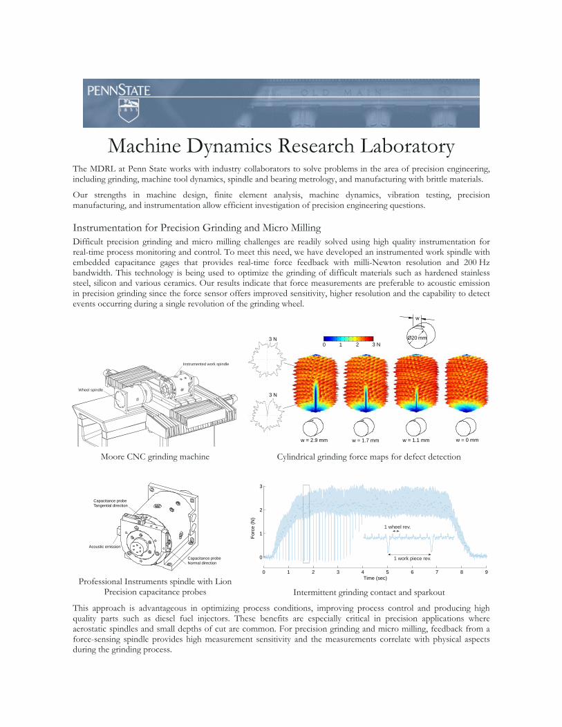
Instrumentation for Precision Grinding and Micro Milling Difficult precision grinding and micro milling challenges are readily solved using high quality instrumentation for real-time process monitoring and control. To meet this need, we have developed an instrumented work spindle with embedded capacitance gages that provides real-time force feedback with milli-Newton resolution and 200 Hz bandwidth. This technology is being used to optimize the grinding of difficult materials such as hardened stainless steel, silicon and various ceramics. Our results indicate that force measurements are preferable to acoustic emission in precision grinding since the force sensor offers improved sensitivity, higher resolution and the capability to detect events occurring during a single revolution of the grinding wheel.
Wheel spindle
Instrumented work spindle
Moore CNC grinding machine
Capacitance probe
Tangential direction
Acoustic emission
Capacitance probe
Normal direction
Professional Instruments spindle with Lion
Precision capacitance probes
w = 2.9 mm w = 1.7 mm w = 1.1 mm w = 0 mm
3 N
3 N3 N210
Ø20 mm
w
Cylindrical grinding force maps for defect detection
0
1
2
3
Fo
rce
(N
)
0 1 2 3 4 5 6 7 8 9
Time (sec)
1 work piece rev.
1 wheel rev.
Intermittent grinding contact and sparkout
This approach is advantageous in optimizing process conditions, improving process control and producing high quality parts such as diesel fuel injectors. These benefits are especially critical in precision applications where aerostatic spindles and small depths of cut are common. For precision grinding and micro milling, feedback from a force-sensing spindle provides high measurement sensitivity and the measurements correlate with physical aspects during the grinding process.
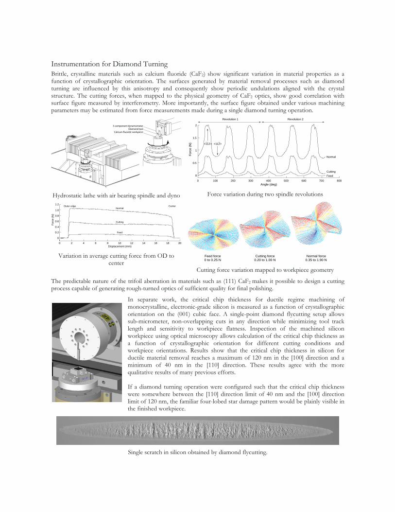
Instrumentation for Diamond Turning Brittle, crystalline materials such as calcium fluoride (CaF2) show significant variation in material properties as a function of crystallographic orientation. The surfaces generated by material removal processes such as diamond turning are influenced by this anisotropy and consequently show periodic undulations aligned with the crystal structure. The cutting forces, when mapped to the physical geometry of CaF2 optics, show good correlation with surface figure measured by interferometry. More importantly, the surface figure obtained under various machining parameters may be estimated from force measurements made during a single diamond turning operation.
3-component dynamometer
Calcium fluoride workpieceDiamond tool
Hydrostatic lathe with air bearing spindle and dyno
0 2 4 6 8 10 12 14 16 18 20
0
0.2
0.4
0.6
0.8
1.0
Displacement (mm)
Fo
rce
(N
)
Normal
Feed
Cutting
1.2Outer edge Center
Variation in average cutting force from OD to
center
0 100 200 300 400 500 600 700 800
0
0.5
1
1.5
2
Angle (deg)
Fo
rce
(N
)
Normal
Feed
Cutting
Revolution 1 Revolution 2
<112> <112>
Force variation during two spindle revolutions
Feed force Cutting force Normal force0 to 0.25 N 0.20 to 1.00 N 0.35 to 1.90 N
Cutting force variation mapped to workpiece geometry
The predictable nature of the trifoil aberration in materials such as (111) CaF2 makes it possible to design a cutting process capable of generating rough-turned optics of sufficient quality for final polishing.
In separate work, the critical chip thickness for ductile regime machining of monocrystalline, electronic-grade silicon is measured as a function of crystallographic orientation on the (001) cubic face. A single-point diamond flycutting setup allows sub-micrometer, non-overlapping cuts in any direction while minimizing tool track length and sensitivity to workpiece flatness. Inspection of the machined silicon workpiece using optical microscopy allows calculation of the critical chip thickness as a function of crystallographic orientation for different cutting conditions and workpiece orientations. Results show that the critical chip thickness in silicon for ductile material removal reaches a maximum of 120 nm in the [100] direction and a minimum of 40 nm in the [110] direction. These results agree with the more qualitative results of many previous efforts. If a diamond turning operation were configured such that the critical chip thickness were somewhere between the [110] direction limit of 40 nm and the [100] direction limit of 120 nm, the familiar four-lobed star damage pattern would be plainly visible in the finished workpiece.
Single scratch in silicon obtained by diamond flycutting.
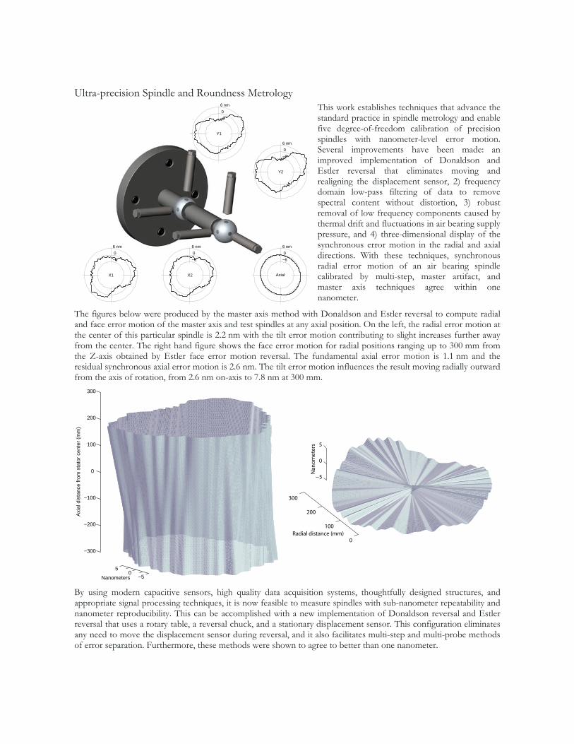
Ultra-precision Spindle and Roundness Metrology This work establishes techniques that advance the standard practice in spindle metrology and enable five degree-of-freedom calibration of precision spindles with nanometer-level error motion. Several improvements have been made: an improved implementation of Donaldson and Estler reversal that eliminates moving and realigning the displacement sensor, 2) frequency domain low-pass filtering of data to remove spectral content without distortion, 3) robust removal of low frequency components caused by thermal drift and fluctuations in air bearing supply pressure, and 4) three-dimensional display of the synchronous error motion in the radial and axial directions. With these techniques, synchronous radial error motion of an air bearing spindle calibrated by multi-step, master artifact, and master axis techniques agree within one nanometer.
The figures below were produced by the master axis method with Donaldson and Estler reversal to compute radial and face error motion of the master axis and test spindles at any axial position. On the left, the radial error motion at the center of this particular spindle is 2.2 nm with the tilt error motion contributing to slight increases further away from the center. The right hand figure shows the face error motion for radial positions ranging up to 300 mm from the Z-axis obtained by Estler face error motion reversal. The fundamental axial error motion is 1.1 nm and the residual synchronous axial error motion is 2.6 nm. The tilt error motion influences the result moving radially outward from the axis of rotation, from 2.6 nm on-axis to 7.8 nm at 300 mm.
−50
5
−300
−200
−100
0
100
200
300
Nanometers
Axia
l d
ista
nce
fro
m s
tato
r ce
nte
r (m
m)
0
100
200
300
−5
0
5
Radial distance (mm)
Nan
omet
ers
By using modern capacitive sensors, high quality data acquisition systems, thoughtfully designed structures, and appropriate signal processing techniques, it is now feasible to measure spindles with sub-nanometer repeatability and nanometer reproducibility. This can be accomplished with a new implementation of Donaldson reversal and Estler reversal that uses a rotary table, a reversal chuck, and a stationary displacement sensor. This configuration eliminates any need to move the displacement sensor during reversal, and it also facilitates multi-step and multi-probe methods of error separation. Furthermore, these methods were shown to agree to better than one nanometer.
−6
0
6 nm
Axial
−6
0
6 nm
X1
−6
0
6 nm
X2
−6
0
6 nm
Y2
−6
0
6 nm
Y1
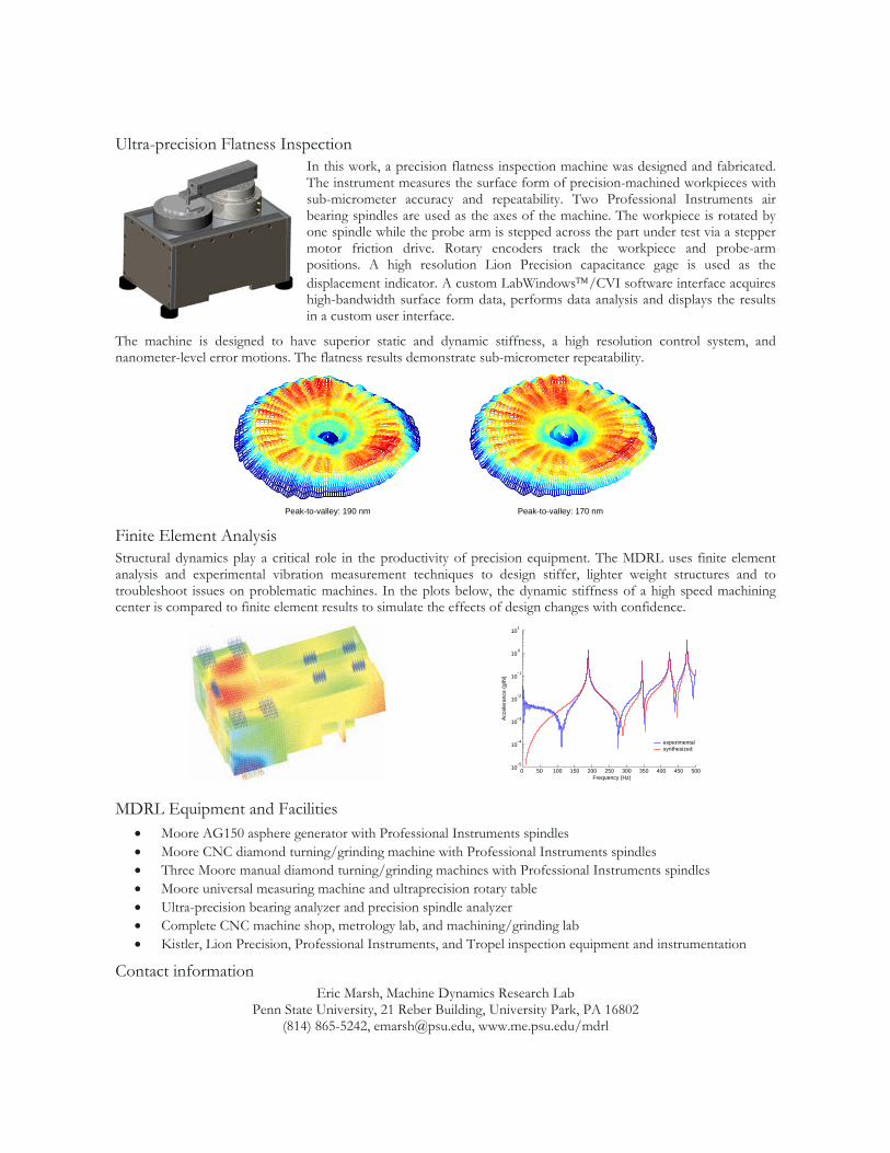
Ultra-precision Flatness Inspection In this work, a precision flatness inspection machine was designed and fabricated. The instrument measures the surface form of precision-machined workpieces with sub-micrometer accuracy and repeatability. Two Professional Instruments air bearing spindles are used as the axes of the machine. The workpiece is rotated by one spindle while the probe arm is stepped across the part under test via a stepper motor friction drive. Rotary encoders track the workpiece and probe-arm positions. A high resolution Lion Precision capacitance gage is used as the displacement indicator. A custom LabWindows™/CVI software interface acquires high-bandwidth surface form data, performs data analysis and displays the results in a custom user interface.
The machine is designed to have superior static and dynamic stiffness, a high resolution control system, and nanometer-level error motions. The flatness results demonstrate sub-micrometer repeatability.
Peak-to-valley: 190 nm Peak-to-valley: 170 nm
Finite Element Analysis Structural dynamics play a critical role in the productivity of precision equipment. The MDRL uses finite element analysis and experimental vibration measurement techniques to design stiffer, lighter weight structures and to troubleshoot issues on problematic machines. In the plots below, the dynamic stiffness of a high speed machining center is compared to finite element results to simulate the effects of design changes with confidence.
0 50 100 150 200 250 300 350 400 450 50010
−5
10−4
10−3
10−2
10−1
100
101
Frequency (Hz)
Acce
lera
nce
(g
/N)
experimental
synthesized
MDRL Equipment and Facilities • Moore AG150 asphere generator with Professional Instruments spindles • Moore CNC diamond turning/grinding machine with Professional Instruments spindles • Three Moore manual diamond turning/grinding machines with Professional Instruments spindles • Moore universal measuring machine and ultraprecision rotary table • Ultra-precision bearing analyzer and precision spindle analyzer • Complete CNC machine shop, metrology lab, and machining/grinding lab • Kistler, Lion Precision, Professional Instruments, and Tropel inspection equipment and instrumentation
Contact information Eric Marsh, Machine Dynamics Research Lab
Penn State University, 21 Reber Building, University Park, PA 16802 (814) 865-5242, [email protected], www.me.psu.edu/mdrl