machine drawing mec-354 shankar sehgal uiet, panjab university, chandigarh
TRANSCRIPT
Machine DrawingMEC-354
Shankar SehgalUIET, Panjab University, Chandigarh


Standard Abbreviations
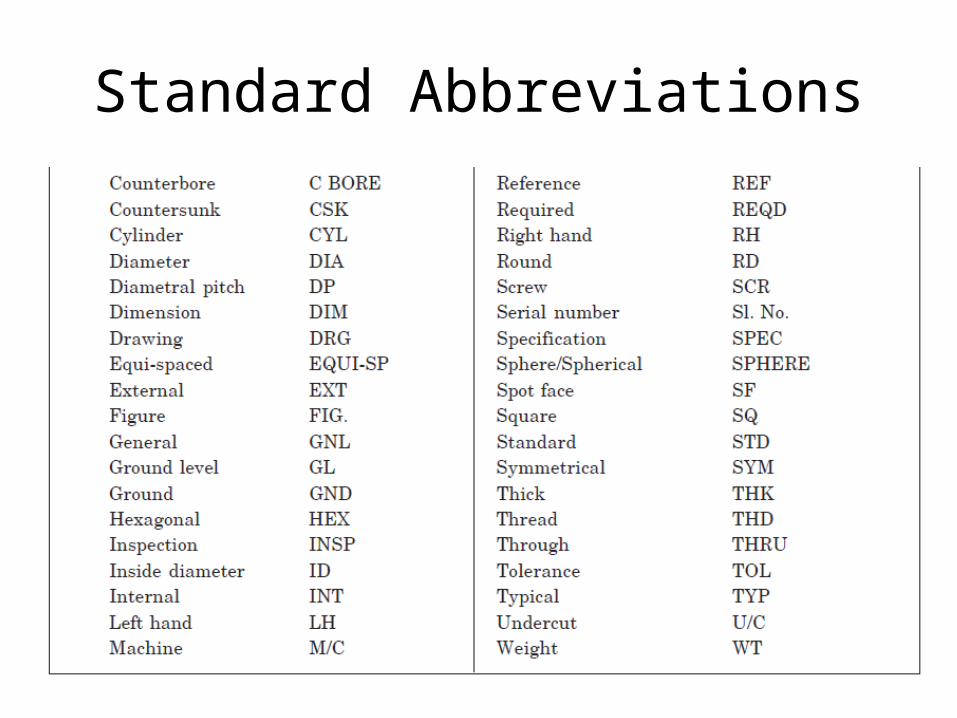
Standard Abbreviations

Standard Abbreviations
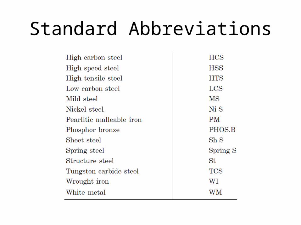
Standard Abbreviations
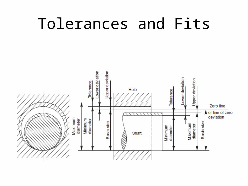
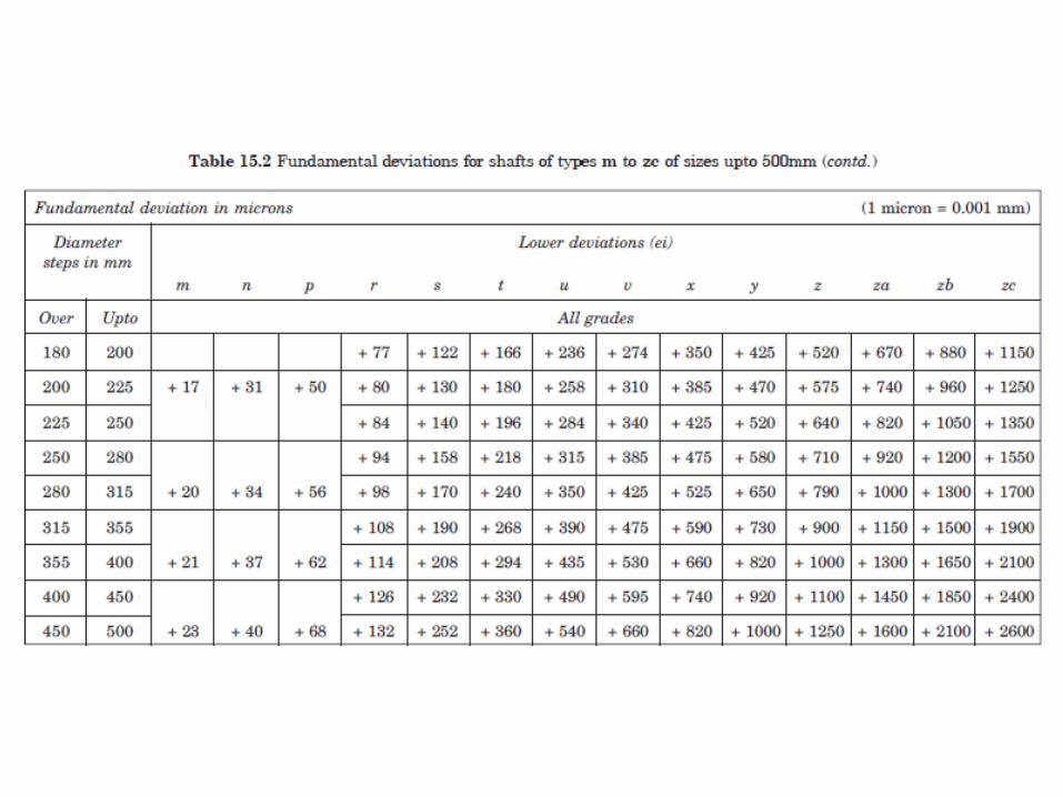
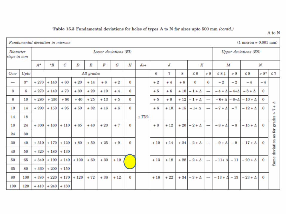
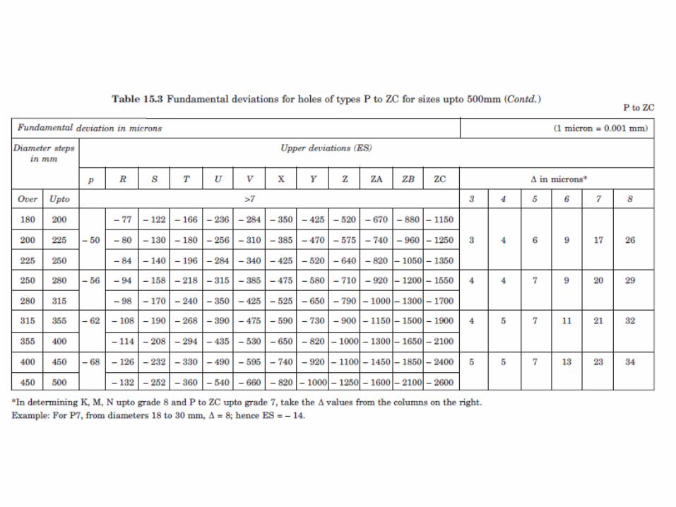
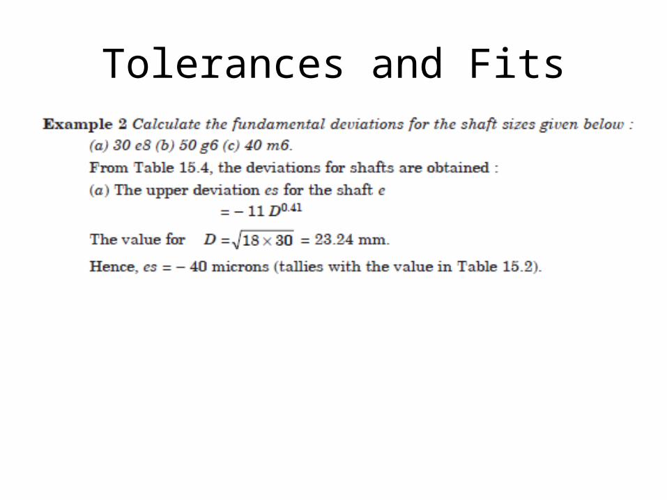
Tolerances and Fits
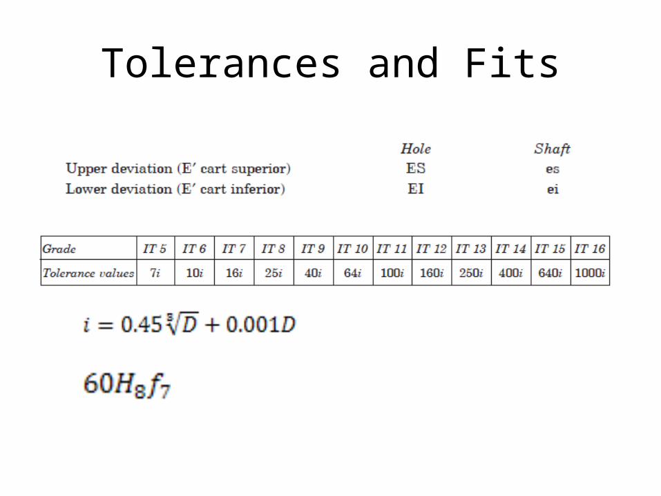
Tolerances and Fits
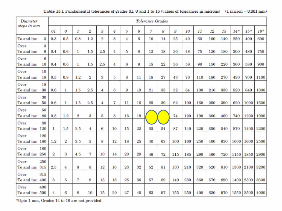
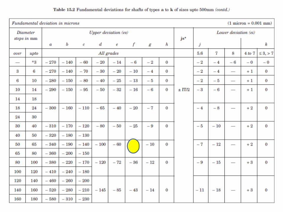

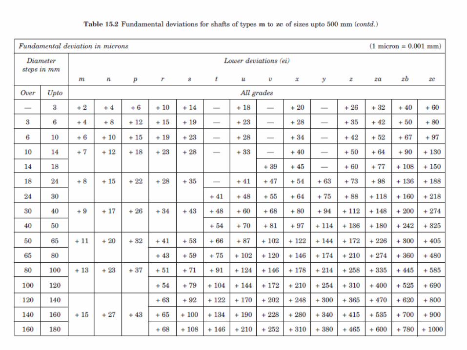


Tolerances and Fits
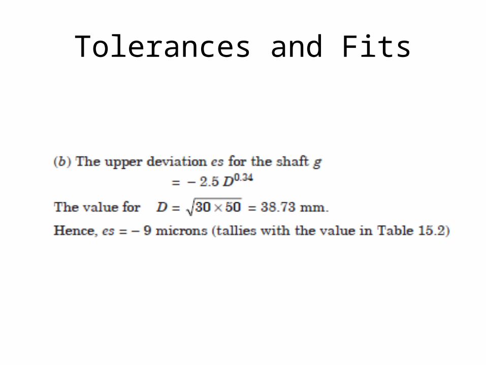
Tolerances and Fits
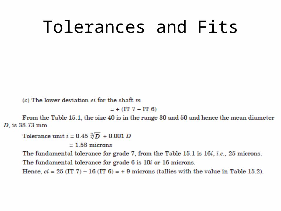
Tolerances and Fits

Tolerancing individual dimensions

Tolerancing individual dimensions

Tolerancing individual dimensions
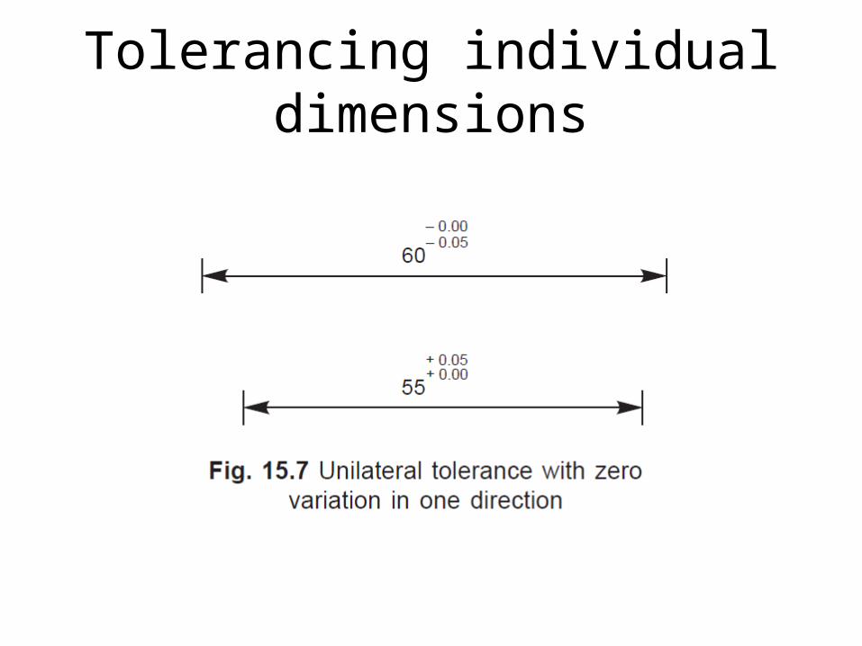
Tolerancing individual dimensions
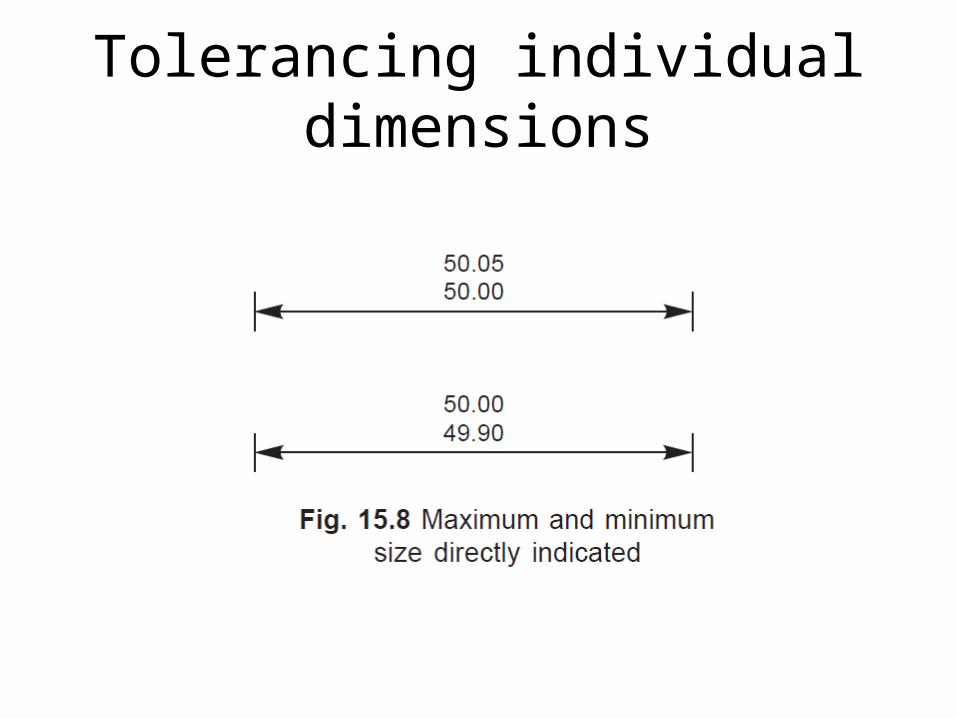
Tolerancing individual dimensions
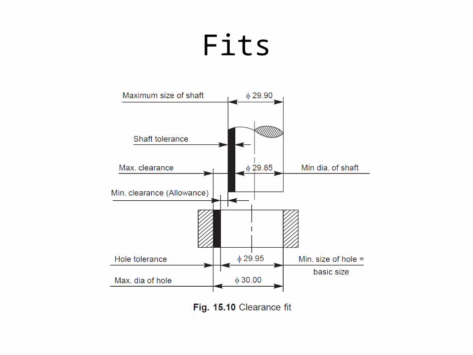
Fits
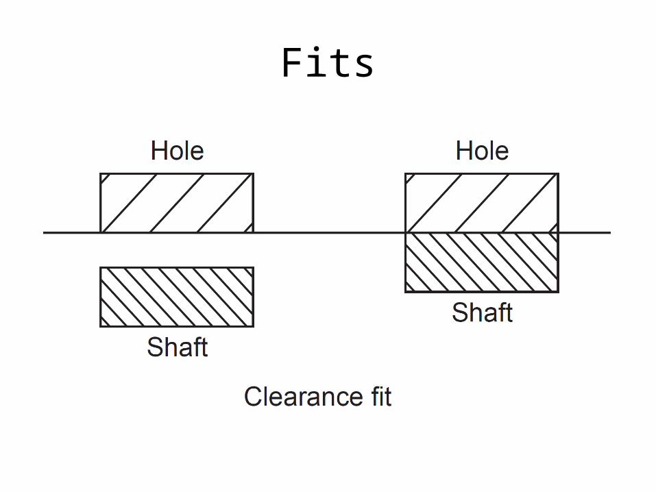
Fits

Fits

Fits
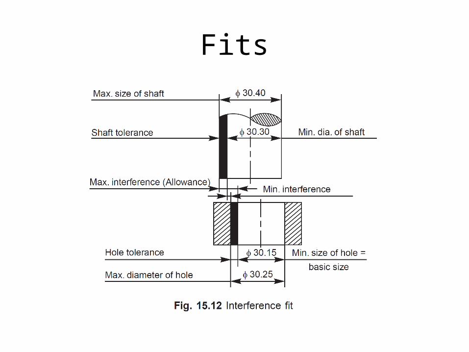
Fits

Fits

Shaft basis system
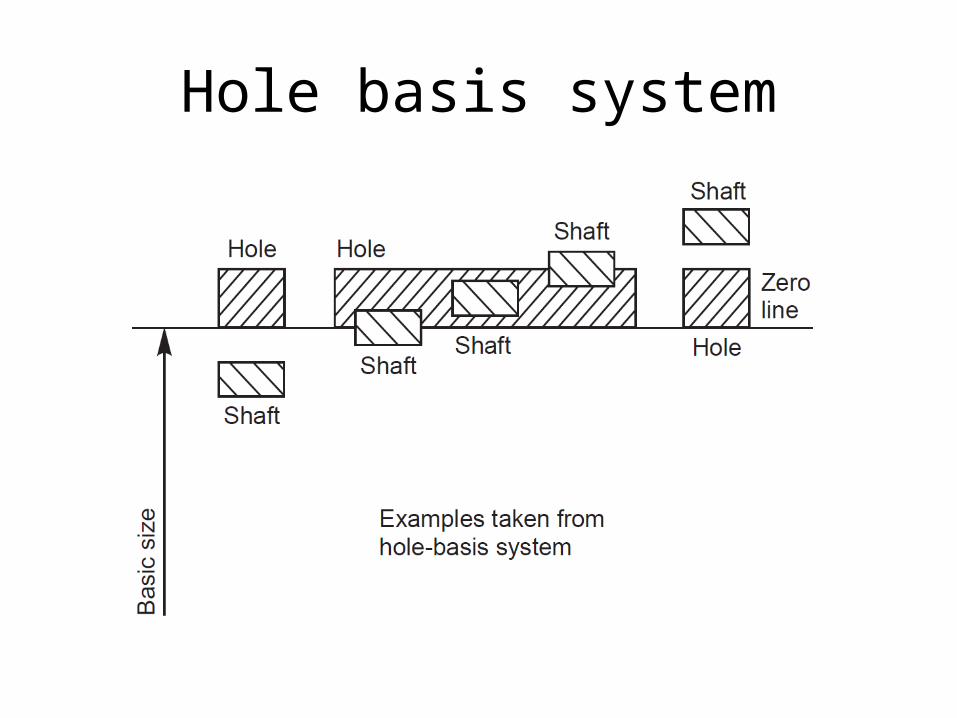
Hole basis system
Machining symbols
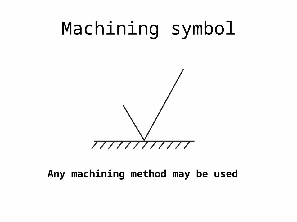
Machining symbol
Any machining method may be used

Machining symbol
Circle means: Material removal not permitted
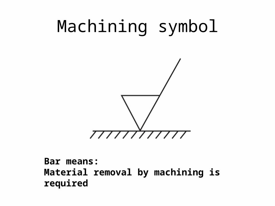
Machining symbol
Bar means: Material removal by machining is required
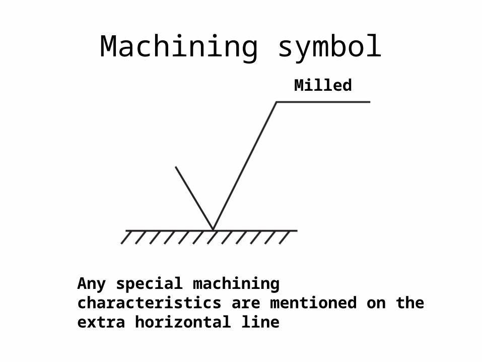
Machining symbol
Any special machining characteristics are mentioned on the extra horizontal line
Milled
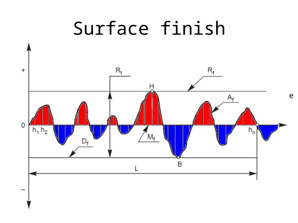
Surface finish
Actual profile
Reference profile
Datum profile Mean profile
Peak-to-valley height
Surface finish parameters
• Actual profile:– It is the profile of the actual surface obtained by
finishing operation• Reference profile:– It is the profile to which the irregularities of the
surface are referred to. It passes through the highest point of the actual profile.
Surface finish parameters
• Datum profile:– It is the profile, parallel to the reference profile. It
passes through the lowest point B of the actual profile.
• Mean profile:– It is that profile, within the sampling length
chosen (L), such that the sum of the material filled areas enclosed above it by the actual profile is equal to the sum of the material-void areas enclosed below it by the profile.
Surface finish parameters
• Peak-to-valley height:– It is the distance from the datum profile to the
reference profile.
• Mean roughness index:– It is the arithmetic mean of the absolute values of
the heights hi between the actual and mean profiles. It is given by,
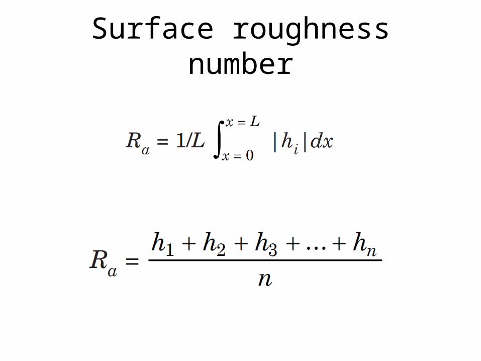
Surface roughness number
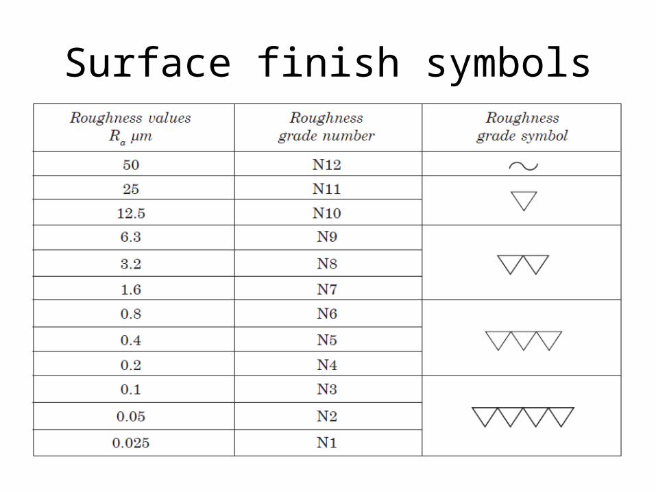
Surface finish symbols
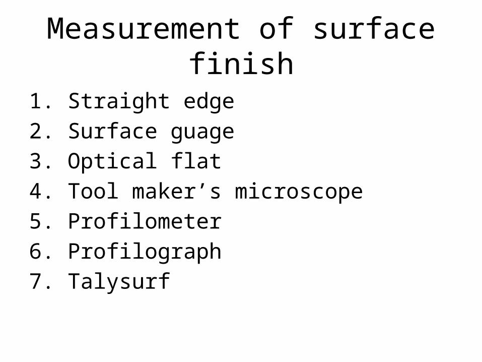
Measurement of surface finish
1. Straight edge2. Surface guage3. Optical flat4. Tool maker’s microscope5. Profilometer6. Profilograph7. Talysurf
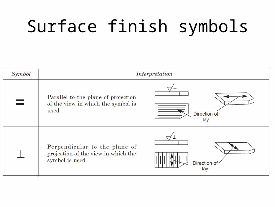
Surface finish symbols
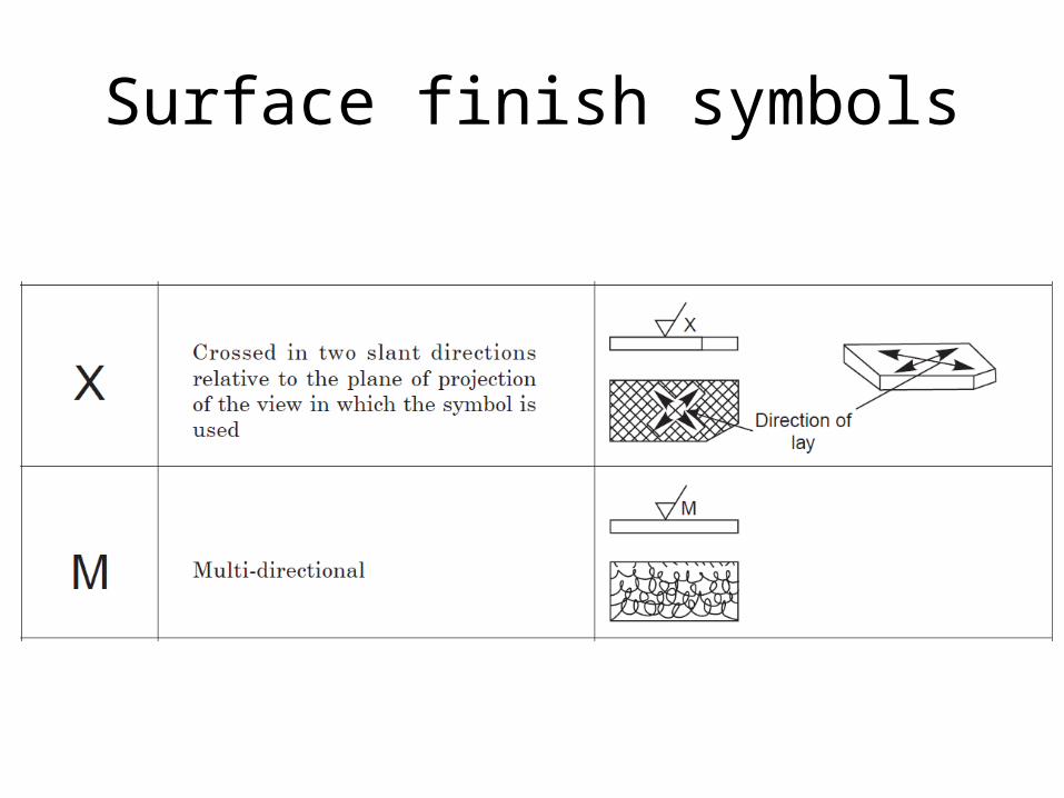
Surface finish symbols
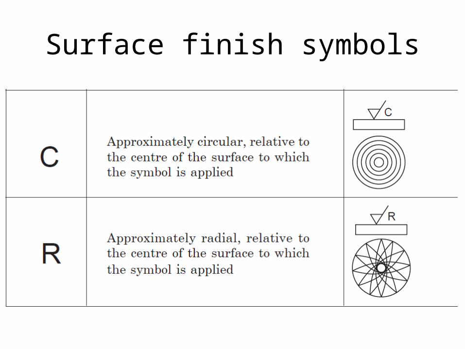
Surface finish symbols
Welding symbols
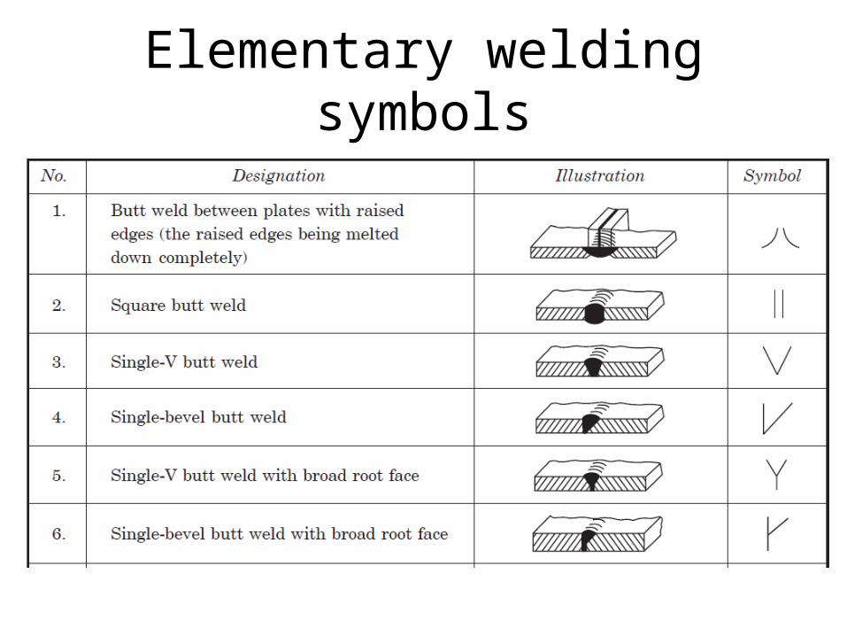
Elementary welding symbols
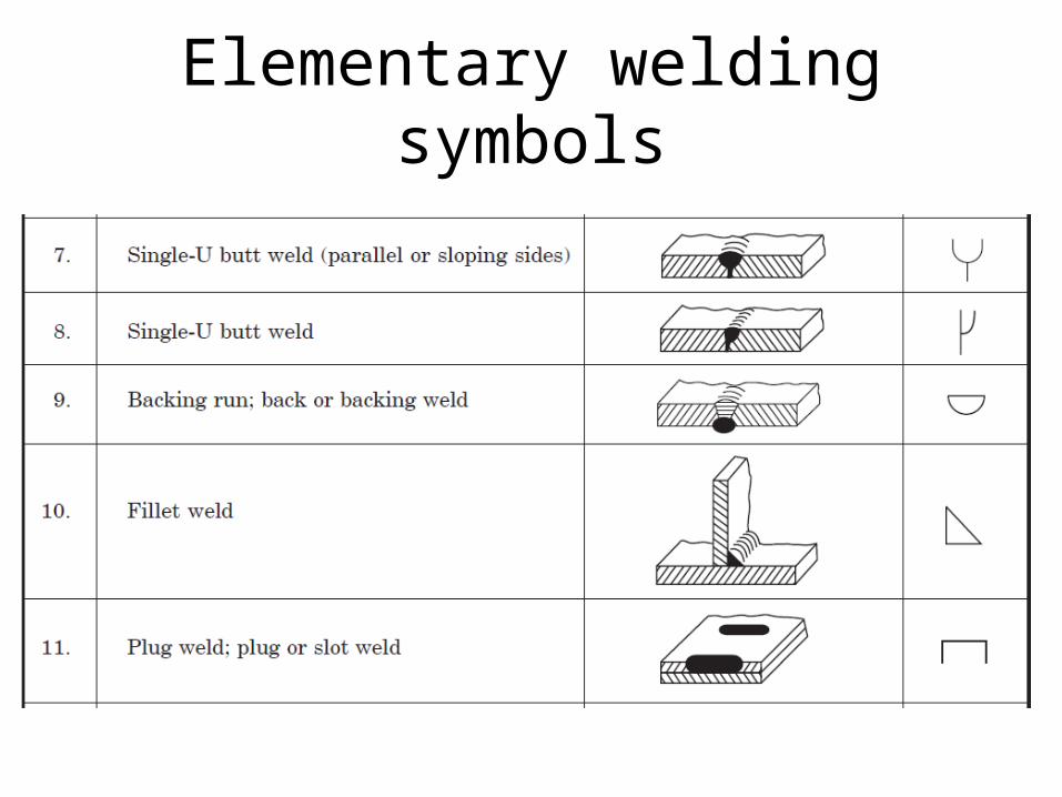
Elementary welding symbols

Elementary welding symbols
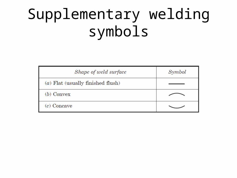
Supplementary welding symbols
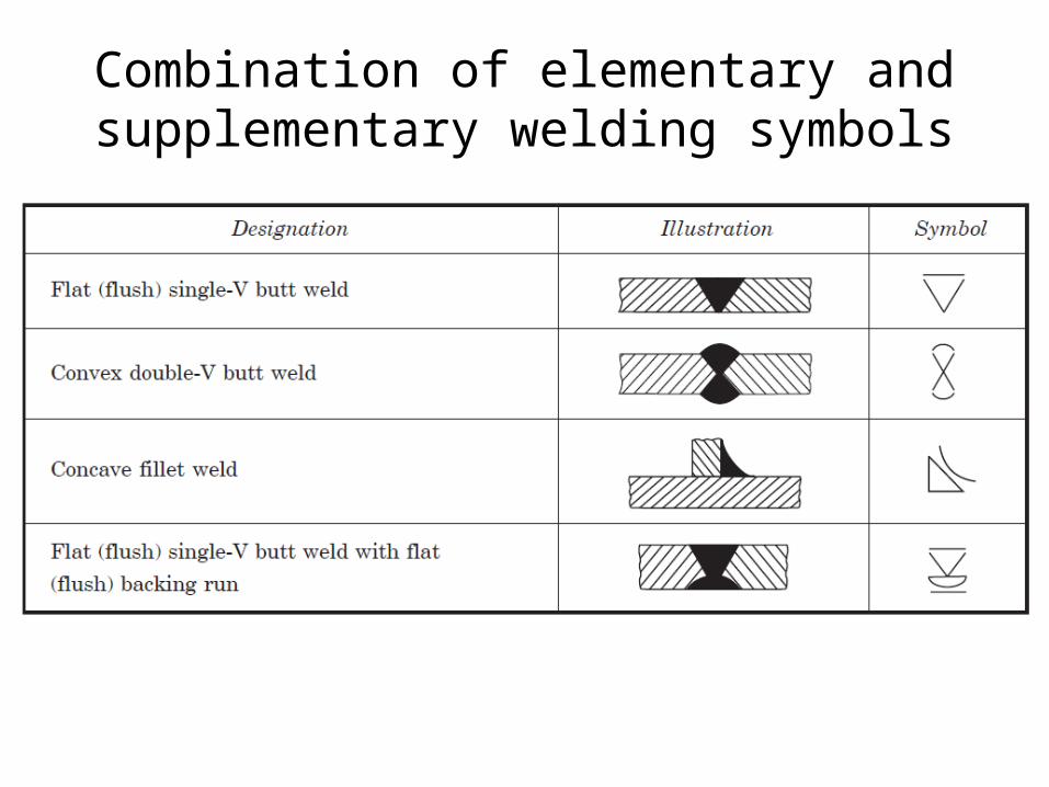
Combination of elementary and supplementary welding symbols
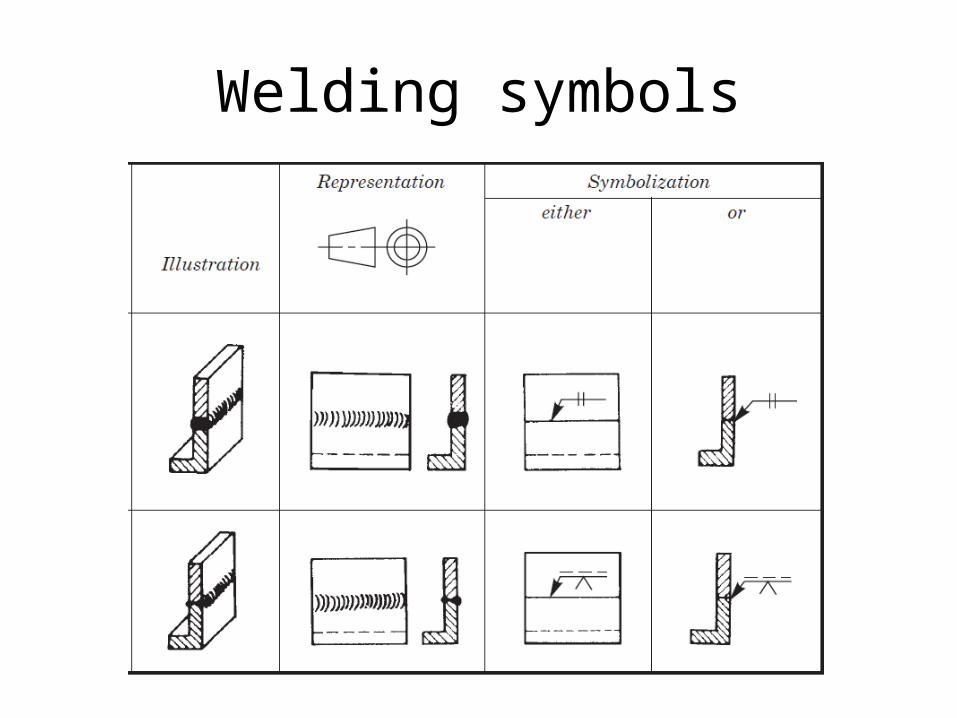
Welding symbols

Indication of edge preparation
Dotted line is on LOWER side. This means that LOWER plate is to be prepared
Welding symbol on continuous line (and not on dotted line).This means that weld is to be made on arrow side (and not on the other side).
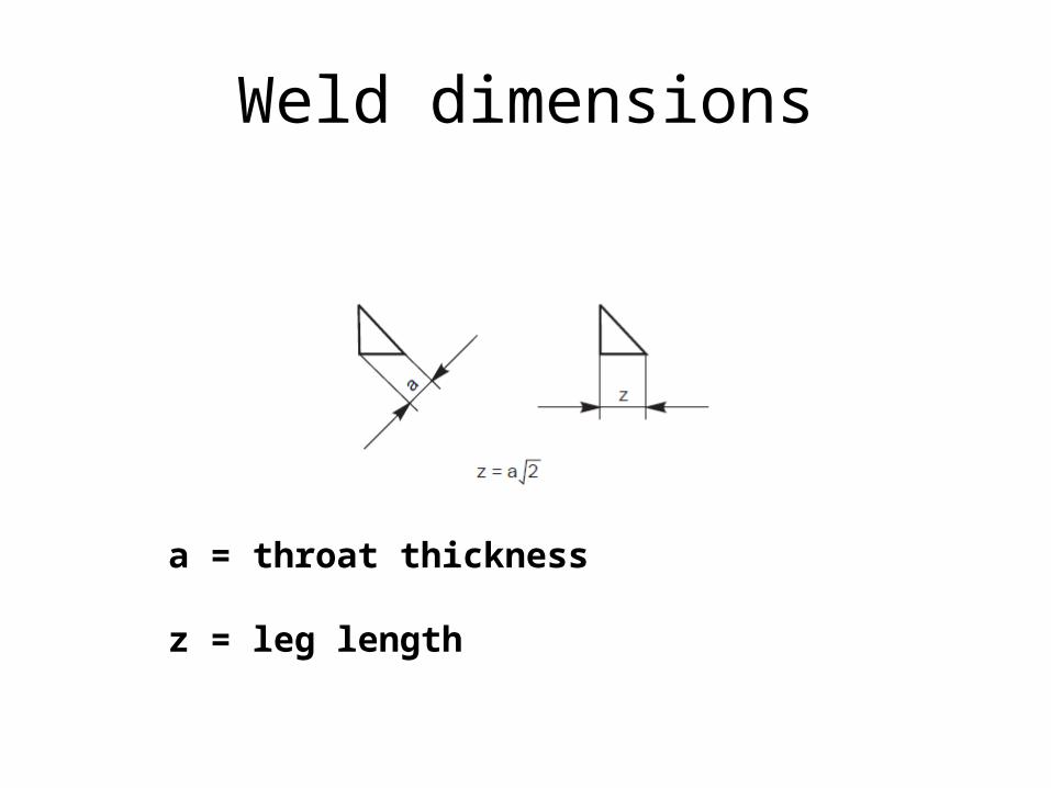
Weld dimensions
a = throat thickness
z = leg length
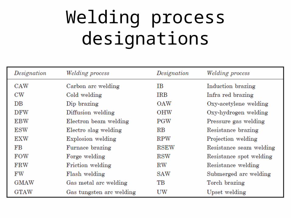
Welding process designations
Screw threads

Screw threads

Screw threads
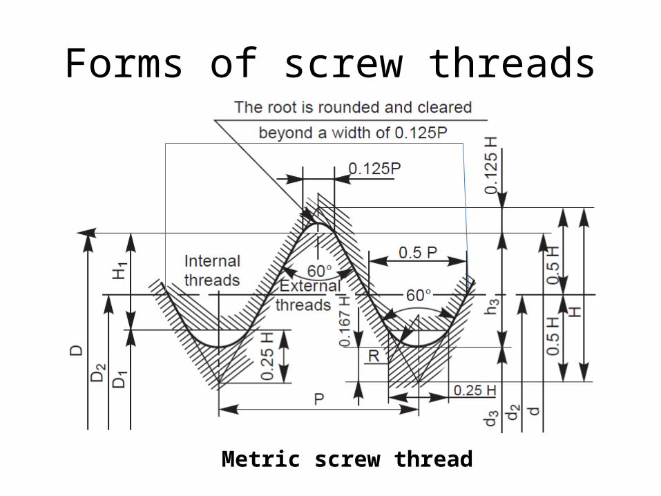
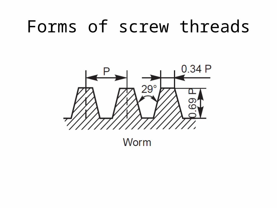
Forms of screw threads
Metric screw thread
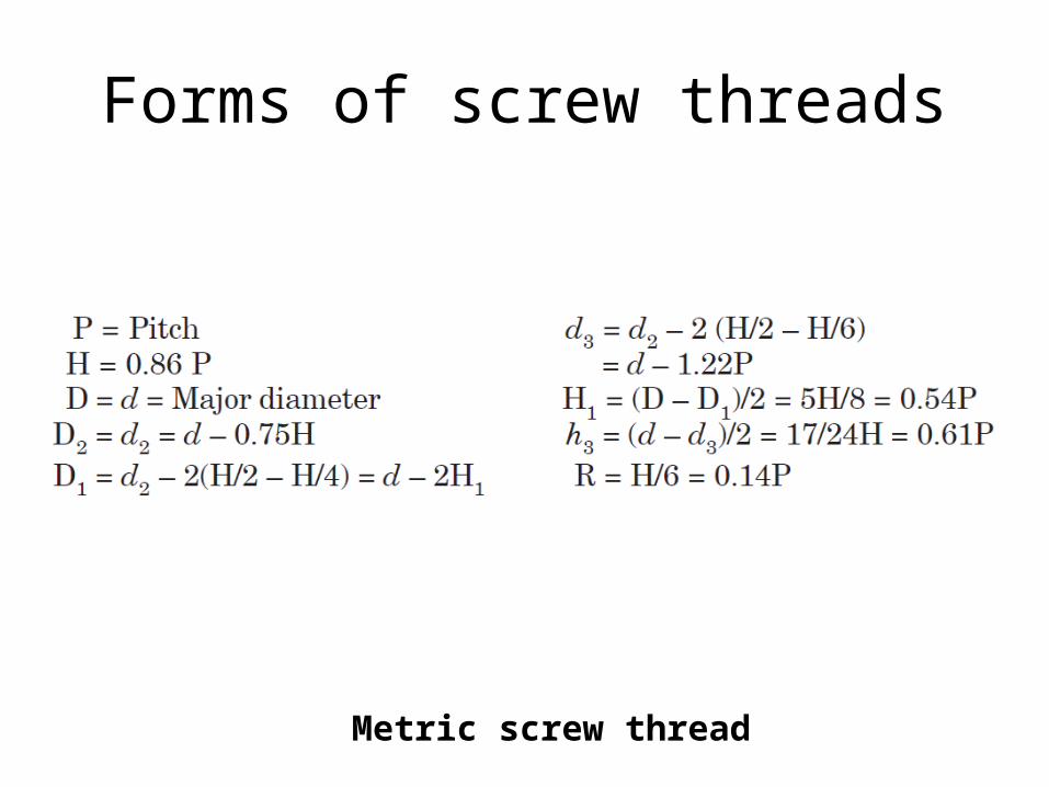
Forms of screw threads
Metric screw thread
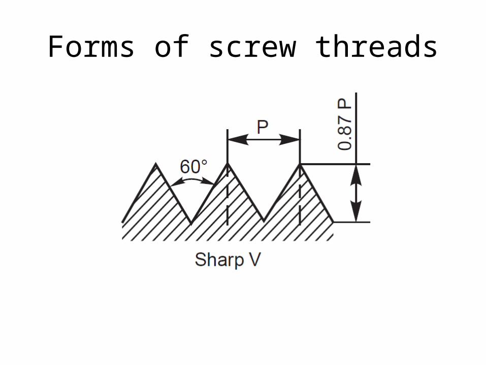
Forms of screw threads
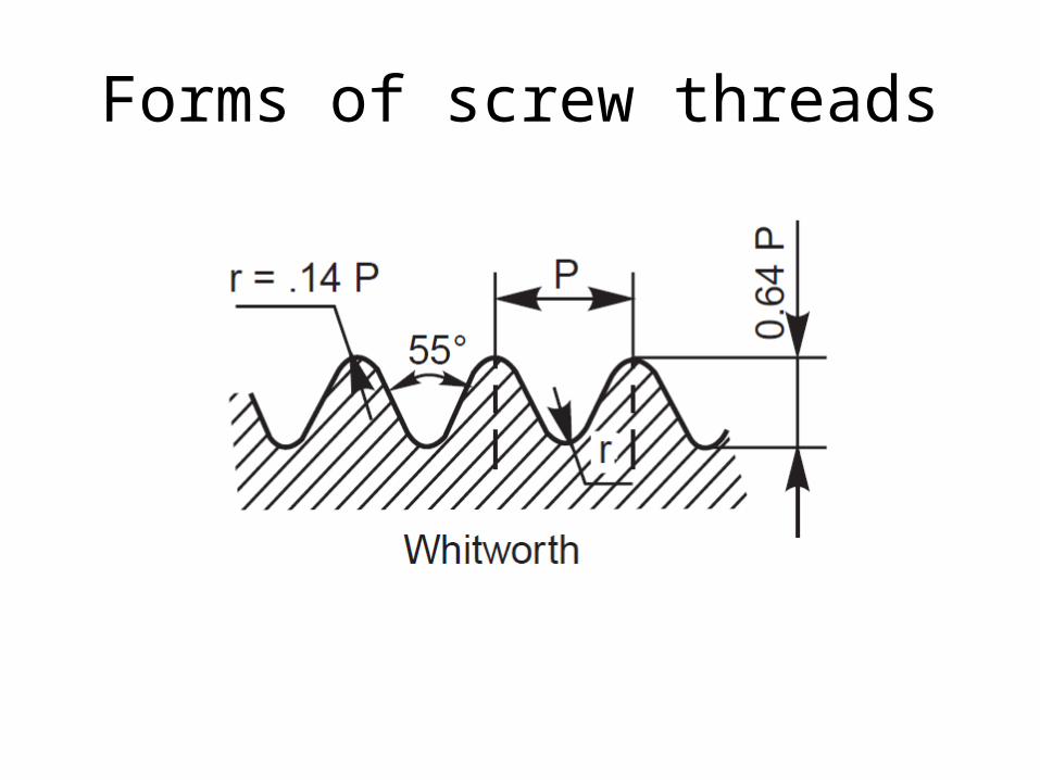
Forms of screw threads
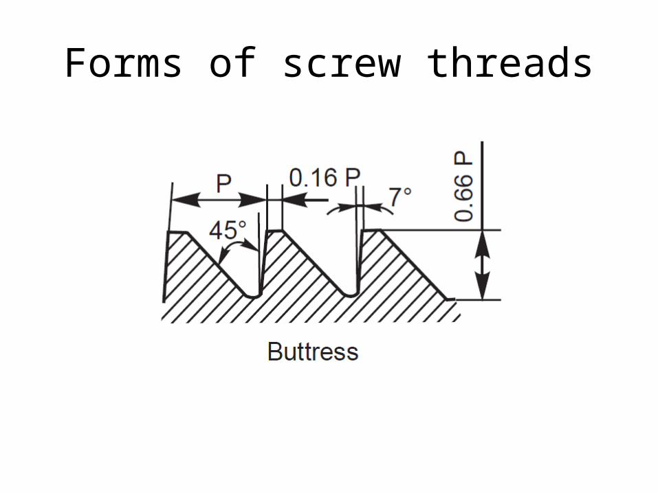
Forms of screw threads

Forms of screw threads

Forms of screw threads
Forms of screw threads
Thread designation
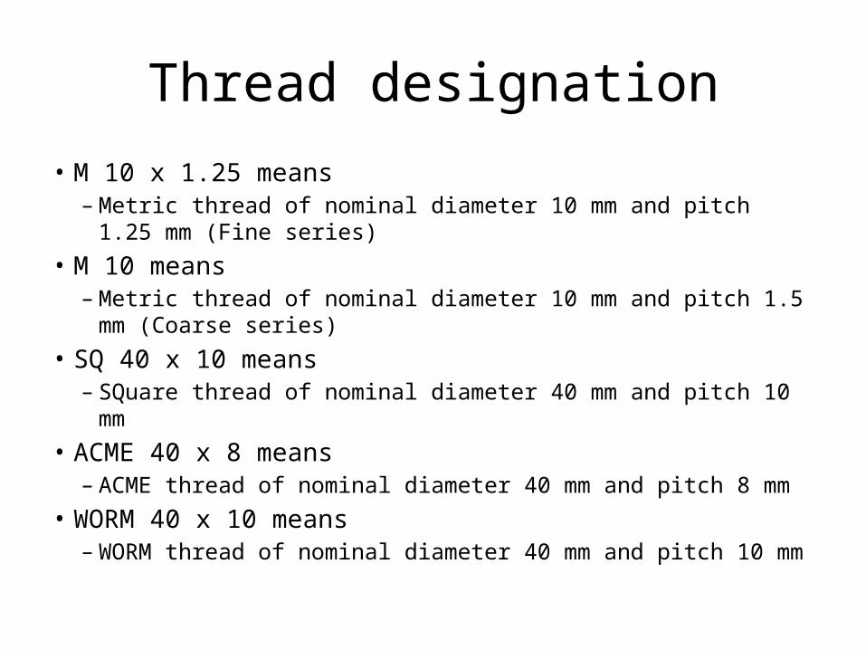
• M 10 x 1.25 means– Metric thread of nominal diameter 10 mm and pitch 1.25 mm (Fine
series)• M 10 means
– Metric thread of nominal diameter 10 mm and pitch 1.5 mm (Coarse series)
• SQ 40 x 10 means– SQuare thread of nominal diameter 40 mm and pitch 10 mm
• ACME 40 x 8 means– ACME thread of nominal diameter 40 mm and pitch 8 mm
• WORM 40 x 10 means– WORM thread of nominal diameter 40 mm and pitch 10 mm

Left hand thread
Side mirror of Activa scooter
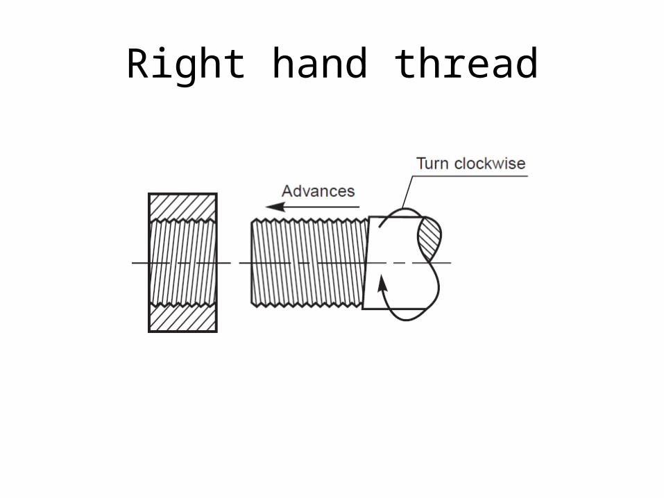
Right hand thread

Conventional representation of threads
• Crests of threads are indicated by a continuous thick line and the roots, by a continuous thin line.
• For hidden screw threads, the crests and roots are indicated by dotted lin
• For threaded parts in section, hatching should be extended to the line defining the crest of the thread.
• In the view from side, the threaded roots are represented by a
• portion of a circle, drawn with a continuous thin line, of length approximately three-quarters of the circumference.
Conventional representation of threads
• The limit of useful length of screw threads is represented by a continuous thick line or a dotted line, depending on its visibility. The length up to which the incomplete threads are formed beyond the useful limit, is known as a run-out. It is represented by two inclined lines.

Conventional representation of threads

Conventional representation of threads
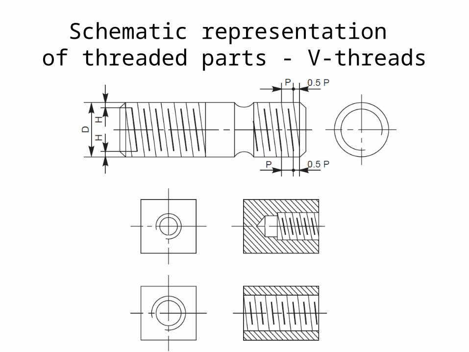
Schematic representation of threaded parts - V-threads
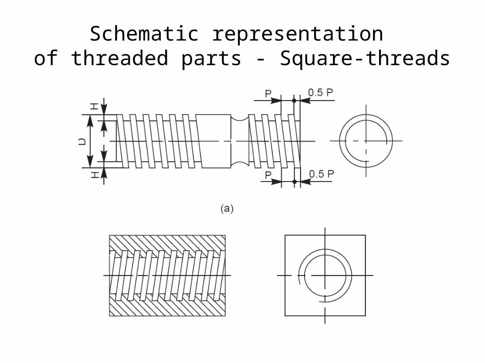
Schematic representation of threaded parts - Square-threads
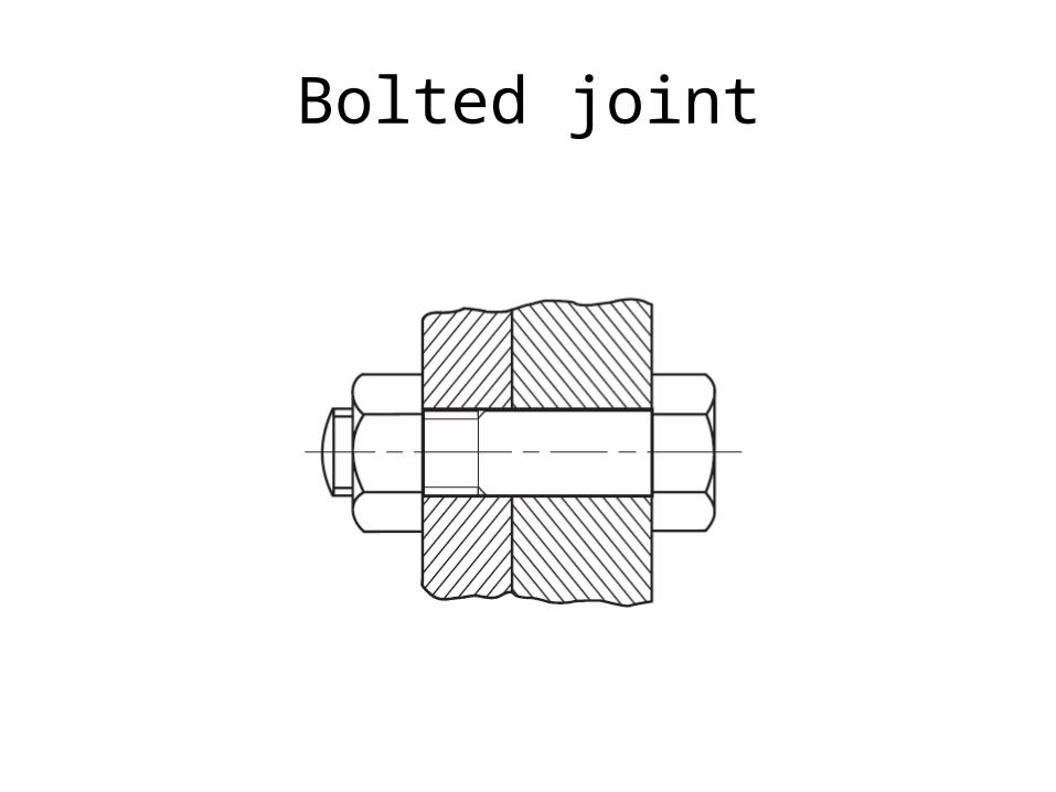
Bolted joint

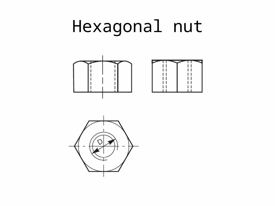
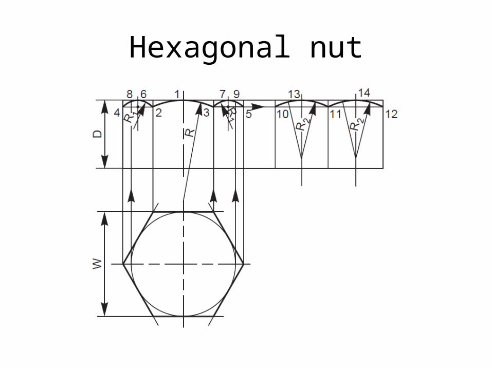
Hexagonal nut
Hexagonal nut
Hexagonal nut
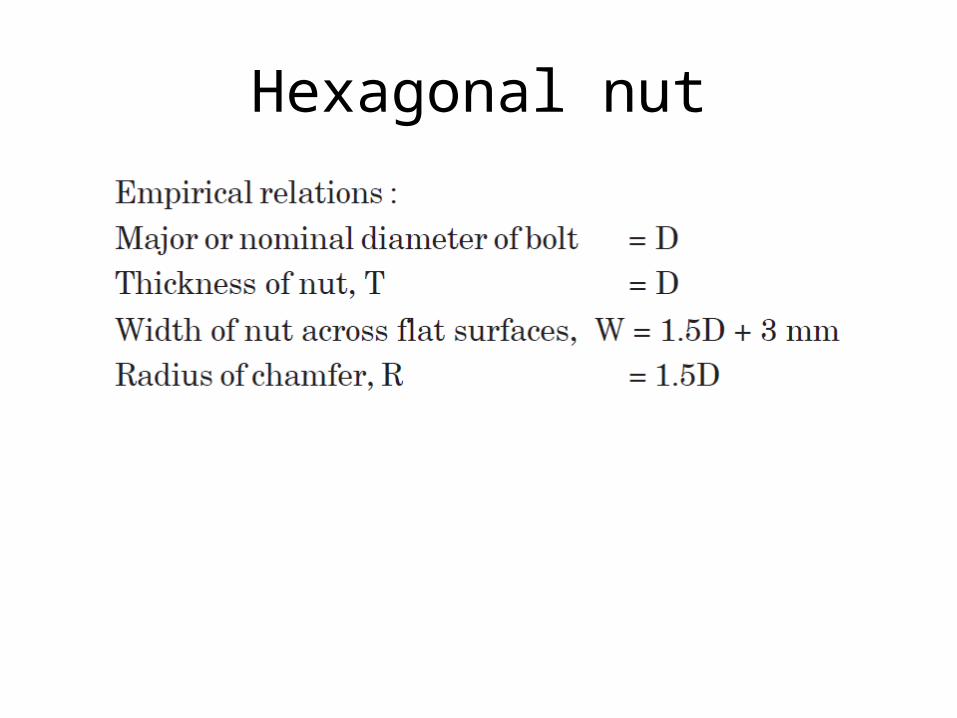
Hexagonal nut

Method of drawing hexagonal nut1. Draw the top view by drawing a circle of diameter, W and describe a regular
hexagon on it, by keeping any two parallel sides of the hexagon, horizontal.2. Project the view from the front, and the view from side, and mark the height equal
to D.3. With radius R, draw the chamfer arc 2-1-3 passing through the point 1 in the front
face.4. Mark points 4 and 5, lying in-line with 2 and 3.5. Locate points 8,9 on the top surface, by projecting from the view from above.6. Draw the chamfers 4–8 and 5–9.7. Locate points 6 and 7, lying at the middle of the outer two faces.8. Draw circular arcs passing through the points 4, 6, 2 and 3, 7, 5, after determining
the radius R1 geometrically.9. Project the view from the side and locate points 10, 11 and 12.10. Mark points 13 and 14, lying at the middle of the two faces (view from the side).11. Draw circular arcs passing through the points 10, 13, 11 and 11, 14, 12, after
determining the radius R2 geometrically.
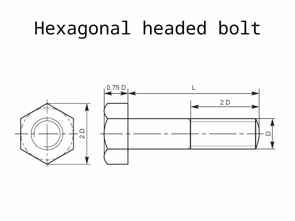
Hexagonal headed bolt
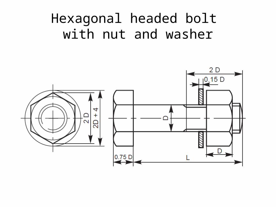
Hexagonal headed bolt with nut and washer
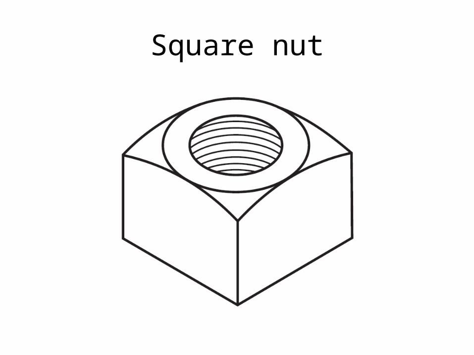
Square nut
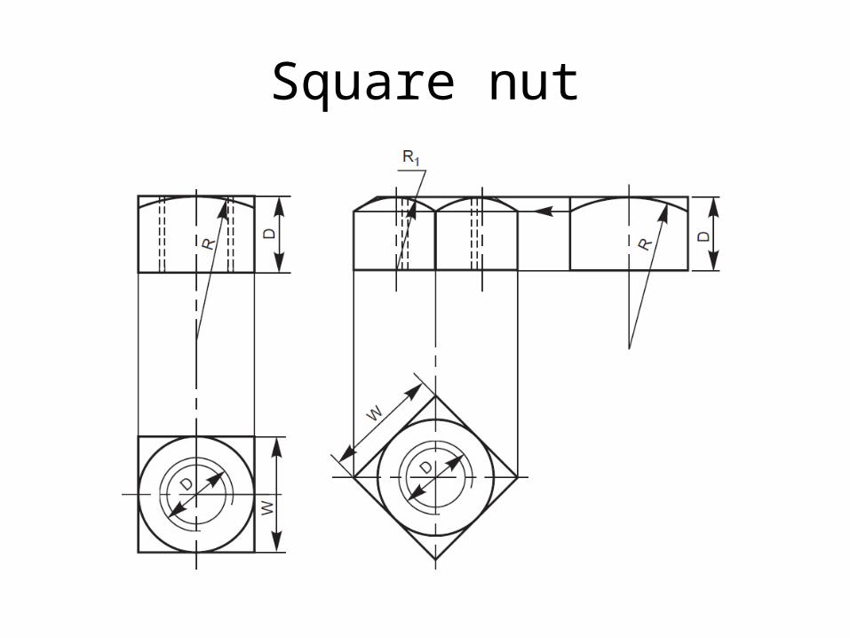
Square nut

Square nut

Square headed bolt
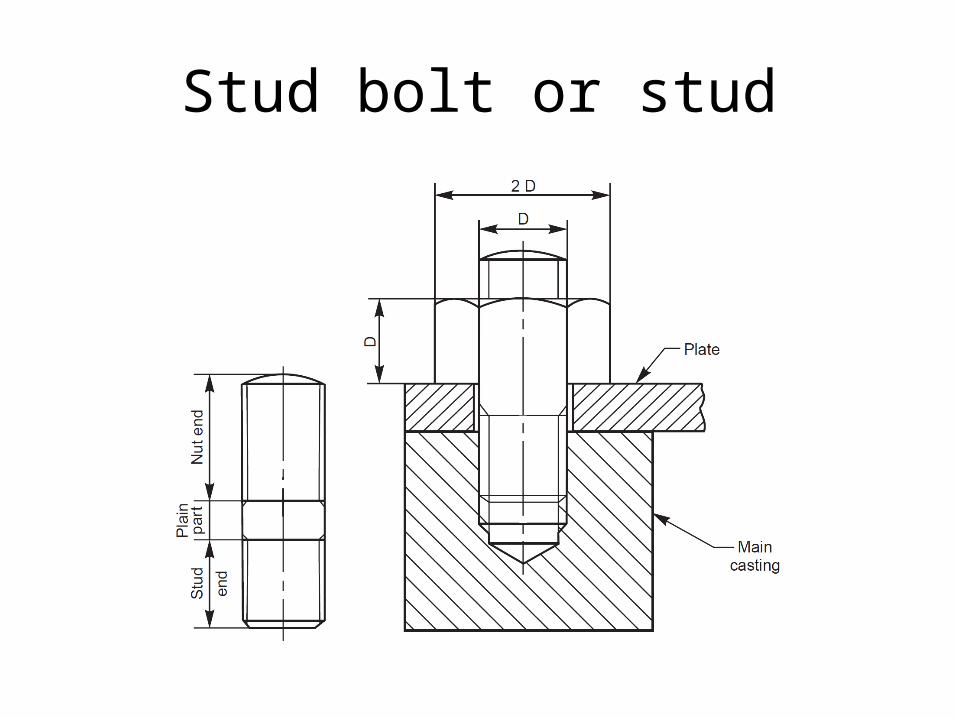
Stud bolt or stud

Nuts
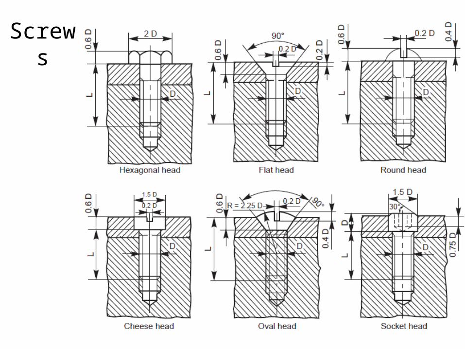
Screws
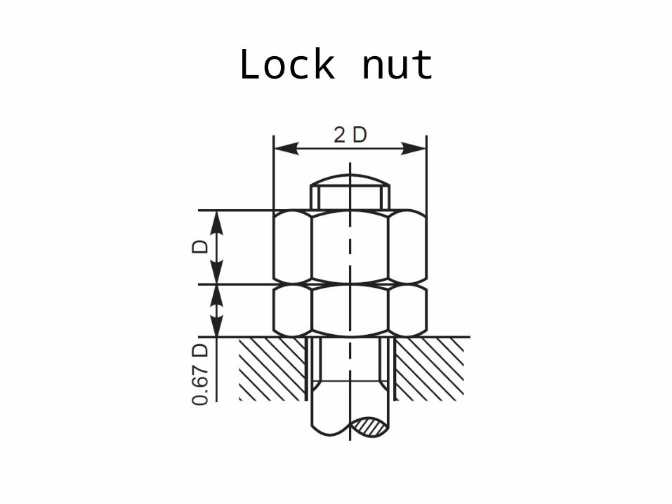
Lock nut

Lock nut
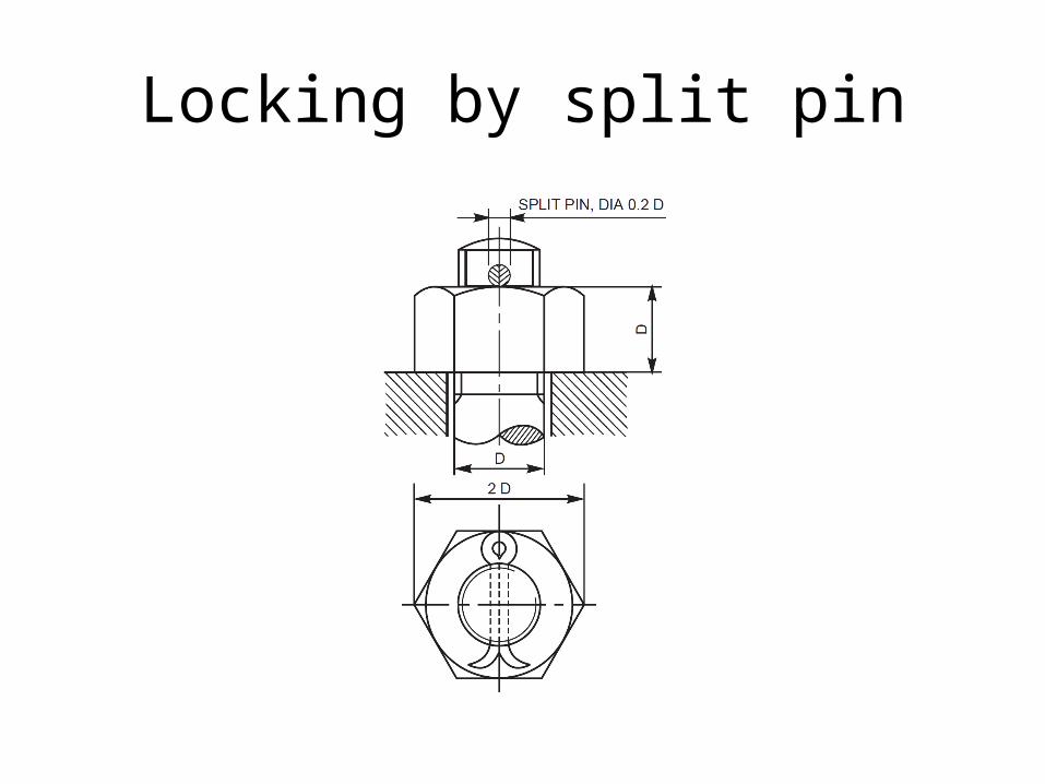
Locking by split pin
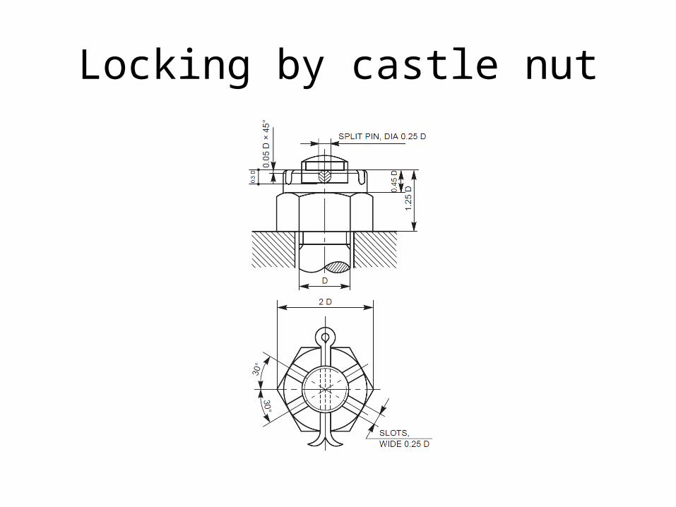
Locking by castle nut
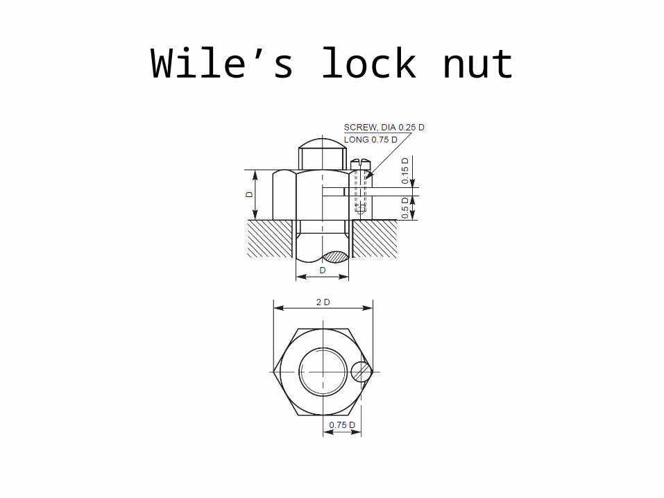
Wile’s lock nut
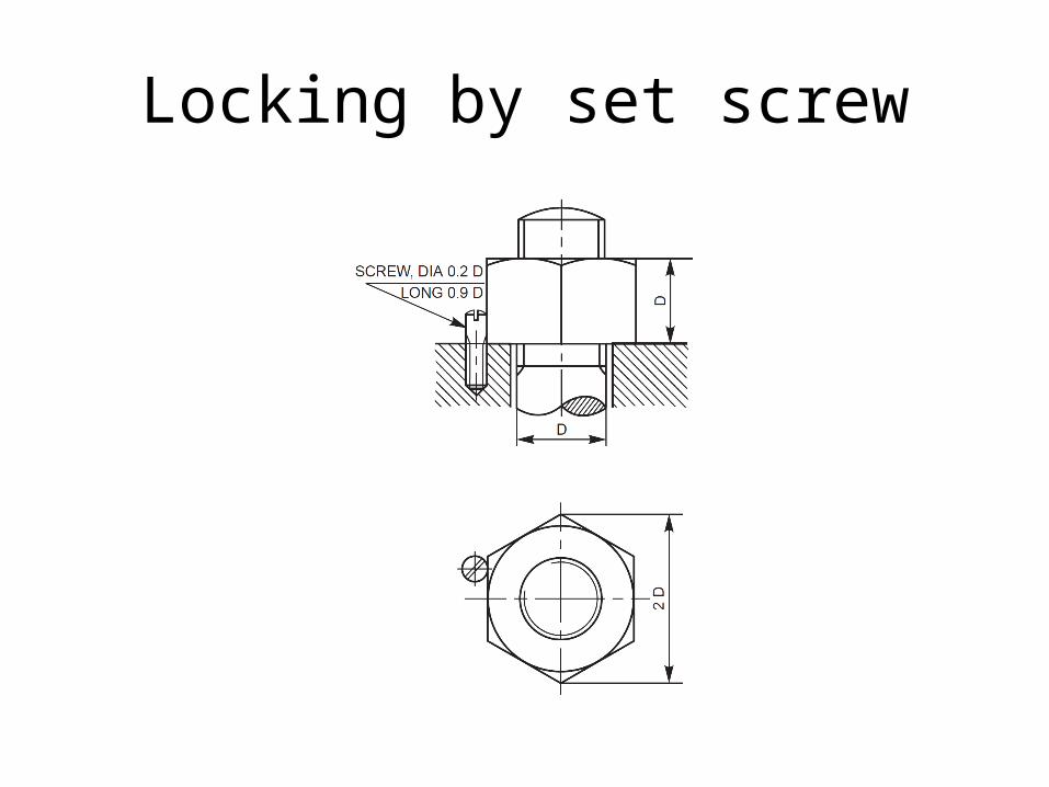
Locking by set screw
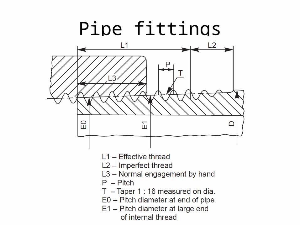
Pipe fittings
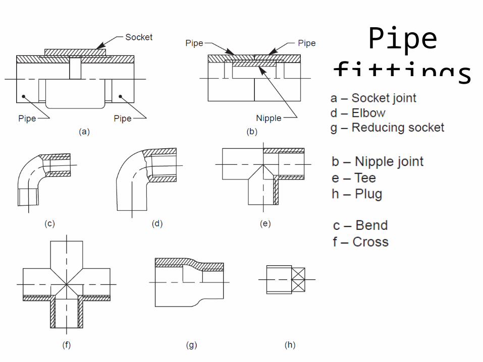
Pipe fittings
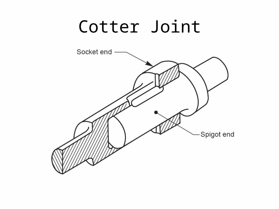
Cotter Joint
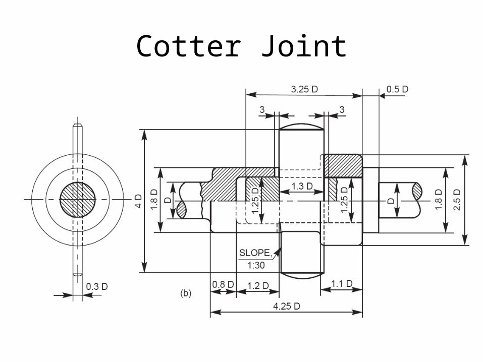
Cotter Joint
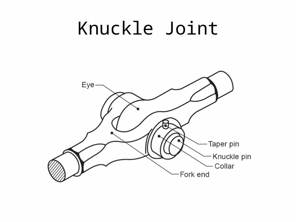
Knuckle Joint
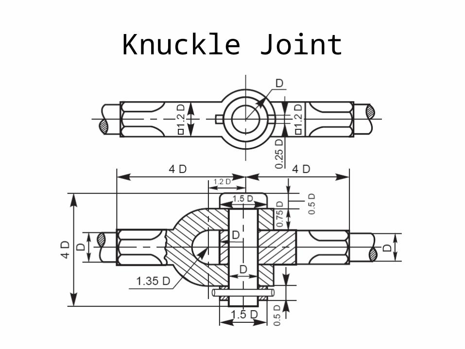
Knuckle Joint
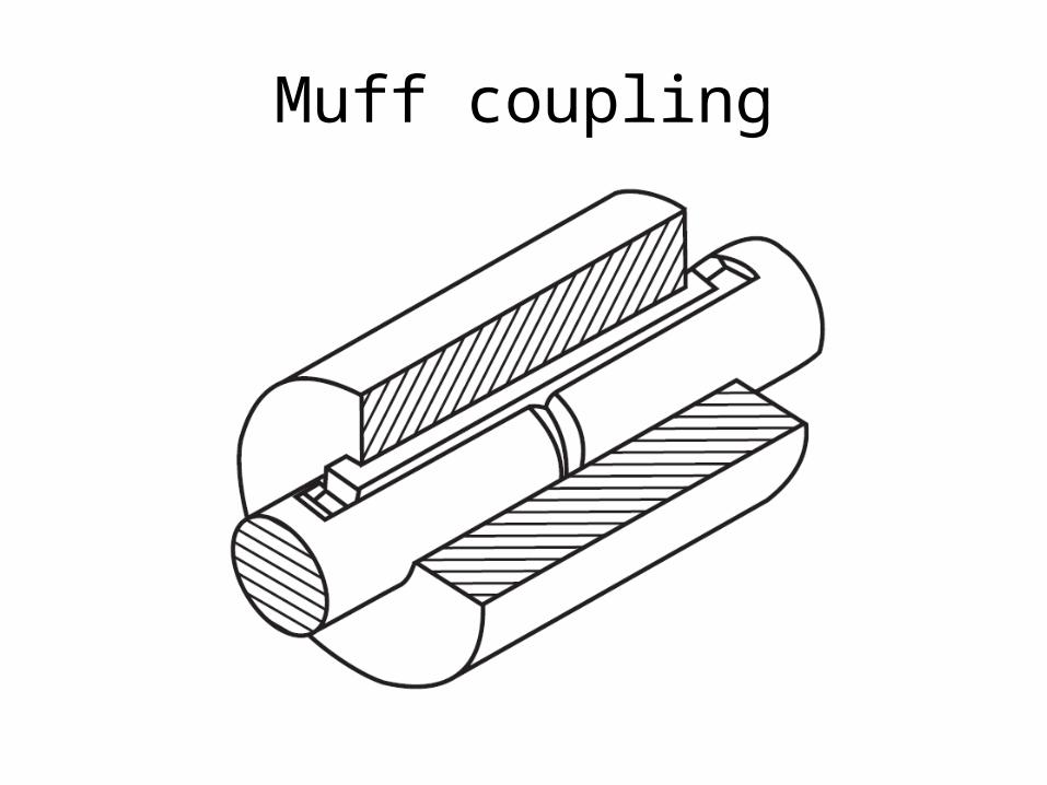
Muff coupling
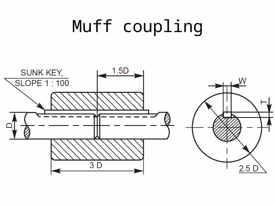
Muff coupling

Flange coupling

Flange coupling
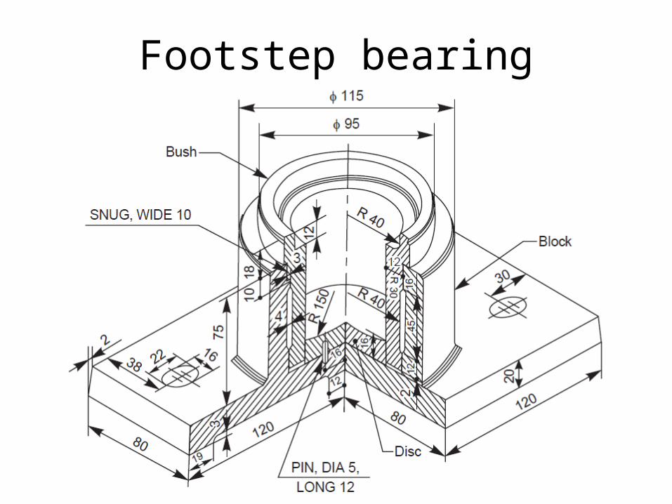
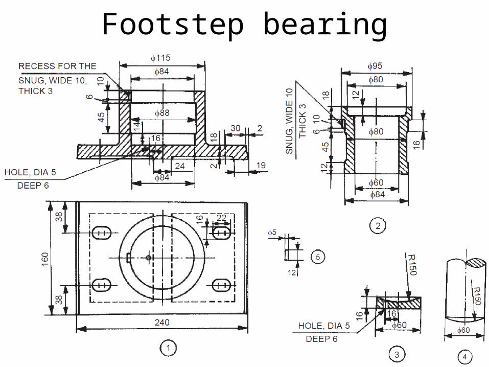
Footstep bearing
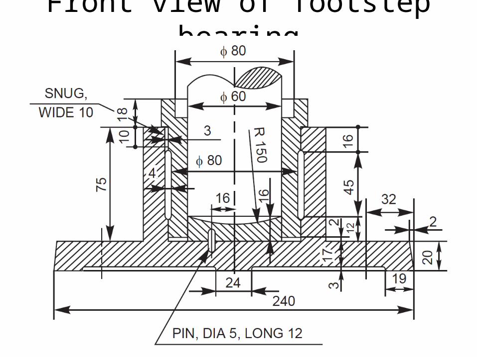
Front view of footstep bearing

Top view of footstep bearing
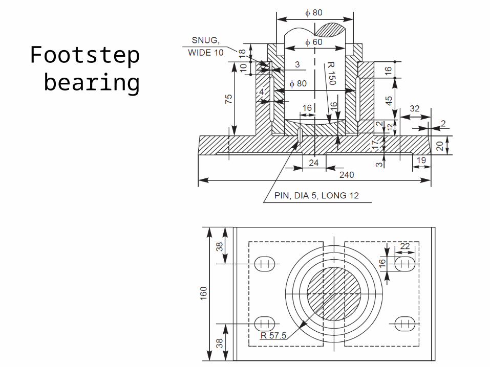
Footstep bearing
Footstep bearing
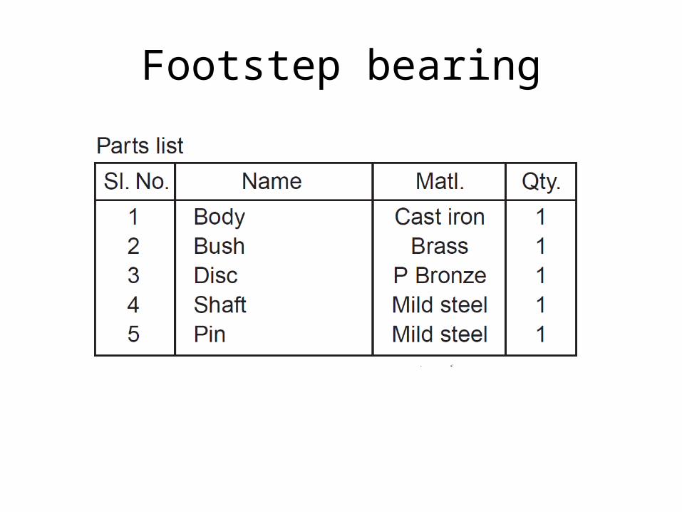
Footstep bearing

Plummer block

Front view of plummer block
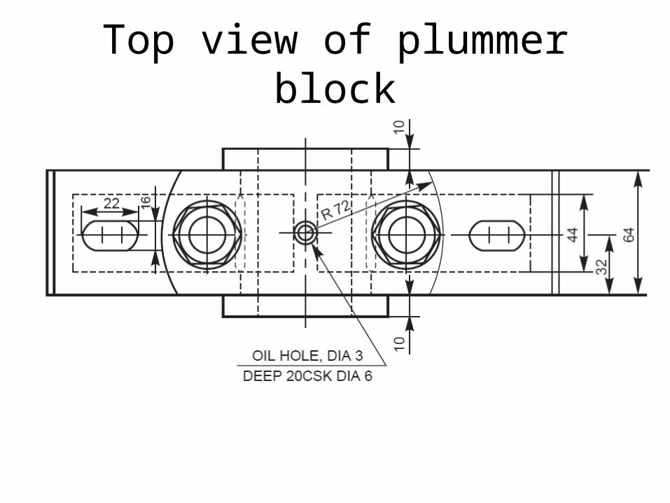
Top view of plummer block
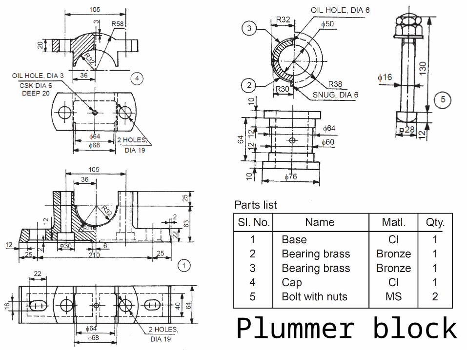
Plummer block

Screw jack
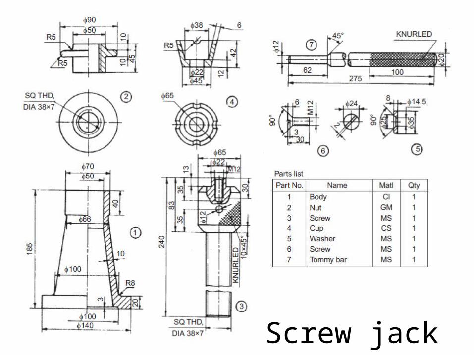
Screw jack
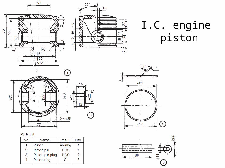
I.C. engine piston

I.C. engine connecting rod

I.C. engine connecting rod


Lathe tail stock