m2233x-x 7 handsfree user manual english polski - …€¦ · m2233x-x 7 handsfree user manual...
TRANSCRIPT

M2233x-x 7 handsfree user manual
please select the language
English
Français
Italiano
Polski
Español
Português
eština
Sloven ina
Suomi
Norsk
Svenska
Dansk
VER:1.0 │ │ 04.04.2014
ABB-Welcome M
Pos: 2 /DinA4 - Anl eitun gen Online /Inh alt/KNX/Doo rEntry /832 20-AP- xxx/Tit elblat t - 832 20-AP-xxx - ABB @ 1 9\m od_ 132 3249 806 476 _15. docx @ 11 108 4 @ @ 1
M2233.-.7" Video hands-free indoorstation
=== E nde der Liste für Tex tma rke C over == =
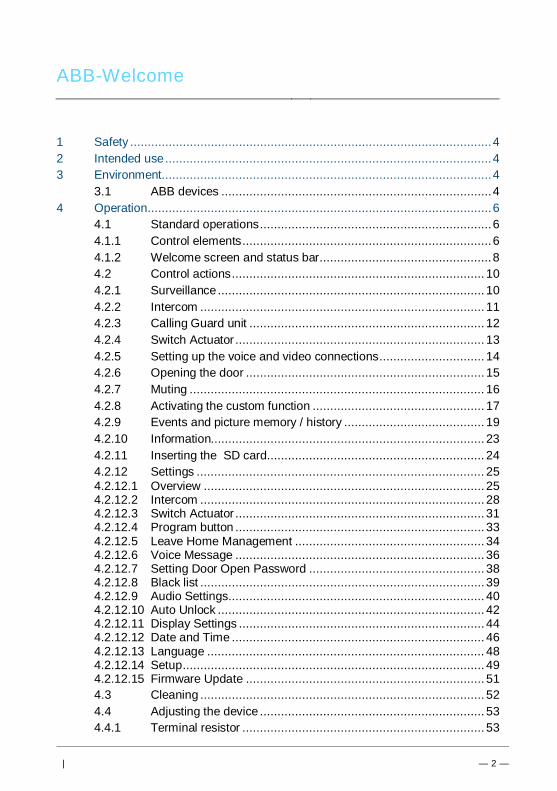
ABB-Welcome
| — 2 —
Pos: 4 /Busc h-Ja ege r (N eust rukt ur)/ Mo dul-St ruktu r/Onli ne-D oku ment ation /Inh altsve rzeich nis ( --> Fü r alle Doku men te <-- )/In haltsve rzeic hnis @ 19\ mod _13 206 490 4438 6_1 5.d ocx @ 109 653 @ @ 1
1 Safety ....................................................................................................... 42 Intended use ............................................................................................. 43 Environment .............................................................................................. 4
3.1 ABB devices ............................................................................. 44 Operation .................................................................................................. 6
4.1 Standard operations .................................................................. 64.1.1 Control elements ....................................................................... 64.1.2 Welcome screen and status bar ................................................. 84.2 Control actions ........................................................................ 104.2.1 Surveillance ............................................................................ 104.2.2 Intercom ................................................................................. 114.2.3 Calling Guard unit ................................................................... 124.2.4 Switch Actuator ....................................................................... 134.2.5 Setting up the voice and video connections .............................. 144.2.6 Opening the door .................................................................... 154.2.7 Muting .................................................................................... 164.2.8 Activating the custom function ................................................. 174.2.9 Events and picture memory / history ........................................ 194.2.10 Information.............................................................................. 234.2.11 Inserting the SD card .............................................................. 244.2.12 Settings .................................................................................. 254.2.12.1 Overview ................................................................................ 254.2.12.2 Intercom ................................................................................. 284.2.12.3 Switch Actuator ....................................................................... 314.2.12.4 Program button ....................................................................... 334.2.12.5 Leave Home Management ...................................................... 344.2.12.6 Voice Message ....................................................................... 364.2.12.7 Setting Door Open Password .................................................. 384.2.12.8 Black list ................................................................................. 394.2.12.9 Audio Settings ......................................................................... 404.2.12.10 Auto Unlock ............................................................................ 424.2.12.11 Display Settings ...................................................................... 444.2.12.12 Date and Time ........................................................................ 464.2.12.13 Language ............................................................................... 484.2.12.14 Setup ...................................................................................... 494.2.12.15 Firmware Update .................................................................... 514.3 Cleaning ................................................................................. 524.4 Adjusting the device ................................................................ 534.4.1 Terminal resistor ..................................................................... 53

ABB-Welcome
| — 3 —
4.4.2 Connection ............................................................................. 545 Technical data......................................................................................... 556 Mounting / Installation.............................................................................. 56
6.1 Requirements for the electrician............................................... 566.2 General installation instructions ............................................... 576.3 Mounting ................................................................................. 58
=== E nde der Liste für Tex tma rke TOC == =
ABB-Welcome M Safety
| — 4 —
Pos: 6 /Busc h-Ja ege r (N eust rukt ur)/ Mo dul-St ruktu r/Onli ne-D oku ment ation /Übe rschri ften (- -> Für alle D okum ent e < --)/ 1. Eb ene/S - T /Sicher heit @ 18\ mod _13 026 127 917 90_ 15.d ocx @ 103 357 @ 1 @ 1
1 SafetyPos: 7 /Busc h-Ja ege r (N eust rukt ur)/ Mo dul-St ruktu r/Onli ne-D oku ment ation /Sicher heit (-- > Für alle Dok um ente <- -)/Wa rn hinweise /Sicher heit - 23 0 V @ 18\m od_ 130 260 681 675 0_15 .docx @ 1 033 08 @ @ 1
WarningElectric voltage!Risk of death and fire due to electrical voltage of 100-240 V.– Work on the 100-240V supply system may only be performed by
authorised electricians!– Disconnect the mains power supply prior to installation and/or
disassembly!
Pos: 8 /Busc h-Ja ege r (N eust rukt ur)/ Mo dul-St ruktu r/Onli ne-D oku ment ation /Übe rschri ften (- -> Für alle D okum ent e < --)/ 1. Eb ene/A - F /Bestim mun gsge mä ßer Geb rau ch @ 18\ mod _13 027 6332 131 6_1 5.do cx @ 1034 83 @ 1 @ 1
2 Intended usePos: 9 /DinA4 - Anl eitun gen Online /Inh alt/KNX/Doo rEntry /832 20-AP- xxx/Besti mmu ngsg em aesse r Ge bra uch - 83 220 -AP-xxx- 500 @ 2 0\mo d_1 324 561 168 699 _15. docx @ 11 272 8 @ @ 1
The M2233x-x is an integral part of the ABB Welcome M door communication systemand operates exclusively with components from this system. The device must only beinstalled in dry indoor rooms.
Pos: 10 /B usch-J aeg er (Neus truk tur )/M odul -Strukt ur/O nline -Doku me ntatio n/Übe rsch rifte n ( --> Fü r alle Doku men te < -- )/1. E bene /U - Z/U mwelt @ 18\ mod _13 026 141 5896 7_1 5.d ocx @ 103 383 @ 1 @ 1
3 EnvironmentPos: 11 /B usch-J aeg er (Neus truk tur )/M odul -Strukt ur/O nline -Doku me ntatio n/Umw elt ( --> Für all e Doku me nte <-- )/Hinweis e/Hinw eis - U mwelt - Hinweis Elektr oge räte @ 1 8\mo d_1 302 763 973 434 _15. docx @ 10 350 0 @ @ 1
Consider the protection of the environment!Used electric and electronic devices must not be disposed of withdomestic waste.– The device contains valuable raw materials which can be recycled.
Therefore, dispose of the device at the appropriate collectingdepot.
Pos: 12 /Di nA4 - A nleitu ngen Onlin e/Ueb ersc hrift en/2 ./ABB Gera ete @ 19 \mo d_1 323 162 843 832_ 15. docx @ 11 087 5 @ 2 @ 1
3.1 ABB devicesPos: 13 /B usch-J aeg er (Neus truk tur )/M odul -Strukt ur/O nline -Doku me ntatio n/Umw elt ( --> Für all e Doku me nte <-- )/Hinweis e/Hinw eis - U mwelt - ABB Elektro ger äte @ 19\ mo d_1 3231 627 458 39_ 15.d ocx @ 110 867 @ @ 1
All packaging materials and devices from ABB bear the markings and test seals forproper disposal. Always dispose of the packaging material and electric devices and theircomponents via the authorized collecting depots and disposal companies.
ABB-Welcome M Environment
| — 5 —
ABB products meet the legal requirements, in particular the laws governing electronicand electrical devices and the REACH ordinance.(EU-Directive 2002/96/EG WEEE and 2002/95/EG RoHS)(EU-REACH ordinance and law for the implementation of the ordinance (EG)No.1907/2006)
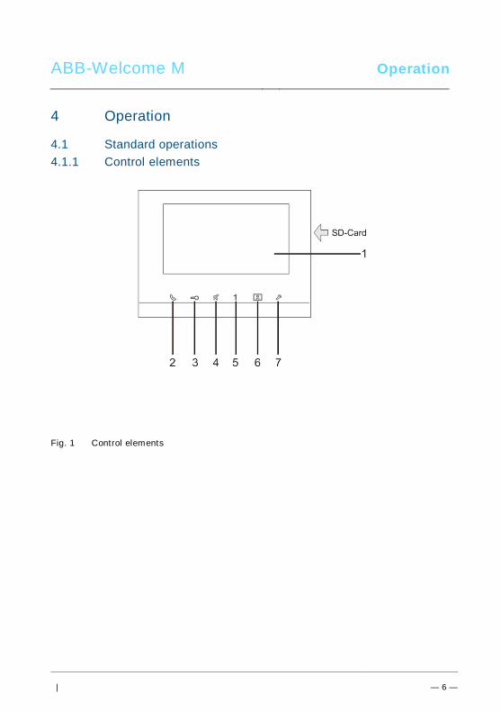
ABB-Welcome M Operation
| — 6 —
Pos: 18 /Di nA4 - A nleitu ngen Onlin e/Ueb ersc hrift en/1 ./Bedie nun g @ 18\m od_ 130 261 392 416 5_15 .docx @ 1 033 65 @ 1 @ 1
4 OperationPos: 19 /Di nA4 - A nleitu ngen Onlin e/Ueb ersc hrift en/2 ./Nor male r Bet rieb @ 18 \mo d_1 302 768 8209 65_ 15. docx @ 10 3540 @ 2 @ 1
4.1 Standard operationsPos: 20 /Di nA4 - A nleitu ngen Onlin e/Ueb ersc hrift en/3 ./Bedie nele men te @ 20\ mod _13 232 6022 055 9_1 5.do cx @ 1 116 47 @ 3 @ 1
4.1.1 Control elementsPos: 21 /Di nA4 - A nleitu ngen Onlin e/In halt/KNX/Do orEnt ry/83 220 -AP-xxx/Be dienel eme nte - 8 322 0-AP-xxx @ 18\ mo d_1 3032 128 536 05_ 15.d ocx @ 103 673 @ @ 1
Fig. 1 Control elements
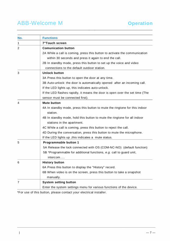
ABB-Welcome M Operation
| — 7 —
No. Functions1 7"Touch screen2 Comunication button
2A While a call is coming, press this button to activate the communication within 30 seconds and press it again to end the call.2B In standby mode, press this button to set up the voice and video
connections to the default outdoor station.3 Unlock button
3A Press this button to open the door at any time.3B Auto-unlock: the door is automatically opened after an incoming call.If the LED lights up, this indicates auto-unlock.If the LED flashes rapidly, it means the door is open over the set time (Thesensor must be connected first).
4 Mute button4A In standby mode, press this button to mute the ringtone for this indoor station.4B In standby mode, hold this button to mute the ringtone for all indoor stations in the apartment.4C While a call is coming, press this button to reject the call.4D During the conversation, press this button to mute the microphone.If the LED lights up ,this indicates a mute status.
5 Programmable button 15A Release the lock connected with OS (COM-NC-NO) (default function)5B *Programmable for additional functions, e.g. call to guard unit,
intercom.....
6 History button6A Press this button to display the "History" record.6B When video is on the screen, press this button to take a snapshot
manually.
7 System setting buttonEnter the system settings menu for various functions of the device.
*For use of this button, please contact your electrical installer.
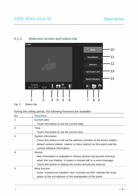
ABB-Welcome M Operation
| — 8 —
4.1.2 Welcome screen and status bar
Fig. 2 Status bar
During the calling period, the following functions are available:No. Functions1 Current date
- Touch this button to set the current date..
2 Time- Touch this button to set the correct time .
3 System information- Touch this button to call up the address (number of the indoor station,
default outdoor station, master or slave station) on this panel and thecurrent software information.
4 History- New information is available in History (events and picture memory)
when this icon flashes. it means a missed call or a voice message.- Touch this button to display the events and picture memory .
5 Mute function- Icons "crossed-out handset" and "crossed-out bell" indicate the mute
status of the microphone or the loudspeaker of the panel.
3 92 4 65 7 8
10
1
11
12
13
14
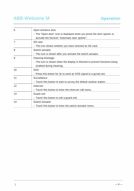
ABB-Welcome M Operation
| — 9 —
6 Open entrance door- The "Open door" icon is displayed when you press the door opener or
activate the function "Automatic door opener".
7 SD card- The icon shows whether you have inserted an SD card.
8 Switch actuator- The icon is shown after you activate the switch actuator.
9 Cleaning blockage- The icon is shown when the display is blocked to prevent functions being
enabled during cleaning.
10 SOS- Press this button for 3s to send an SOS signal to a gurad unit.
11 Surveillance- Touch this button to start to survey the default outdoor station .
12 Intercom- Touch this button to enter the intercom call menu.
13 Guard unit- Touch this button to call a guard unit.
14 Switch Actuator- Touch this button to enter the switch actuator menu.
Pos: 29 /B usch-J aeg er (Neus truk tur )/M odul -Strukt ur/O nline -Doku me ntatio n/Steu er mod ule - Onlin e-Dok ume ntati on ( -- > Für alle Dok ume nte <- -)/ +++ ++ ++ +++ ++ S eiten umb ruch + +++ ++ ++ +++ + @ 9\m od_ 126 8898 668 093 _0. docx @ 521 49 @ @ 1
Pos: 22 /B usch-J aeg er (Neus truk tur )/M odul -Strukt ur/O nline -Doku me ntatio n/Steu er mod ule - Onlin e-Dok ume ntati on ( -- > Für alle Dok ume nte <- -)/ +++ ++ ++ +++ ++ S eiten umb ruch + +++ ++ ++ +++ + @ 9\m od_ 126 8898 668 093 _0. docx @ 521 49 @ @ 1
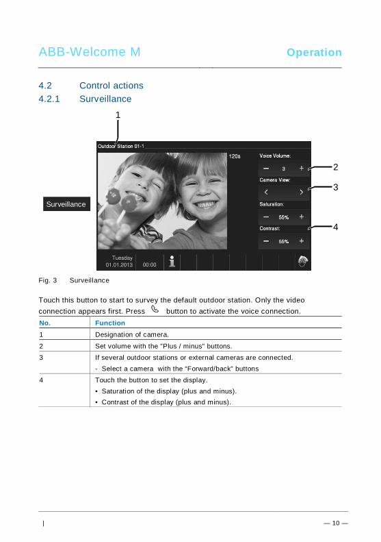
ABB-Welcome M Operation
| — 10 —
Pos: 26 /Di nA4 - A nleitu ngen Onlin e/Ueb ersc hrift en/2 ./Bedie nakti onen @ 2 0\m od_ 1323 262 294 281 _15. docx @ 11 191 1 @ 2 @ 1
4.2 Control actionsPos: 27 /Di nA4 - A nleitu ngen Onlin e/Ueb ersc hrift en/3 ./Spr ech- und Videov erbi ndu ng @ 20\ mod _13 232 6236 870 0_1 5.do cx @ 1119 27 @ 3 @ 1
4.2.1 SurveillancePos: 28 /Di nA4 - A nleitu ngen Onlin e/In halt/KNX/Do orEnt ry/83 220 -AP-xxx/Sp rech - u nd Vide over bind ung - 8 322 0-AP-xxx @ 20\ mo d_1 3232 623 418 52_ 15.d ocx @ 111 919 @ @ 1
Fig. 3 Surveillance
Touch this button to start to survey the default outdoor station. Only the videoconnection appears first. Press button to activate the voice connection.No. Function1 Designation of camera.
2 Set volume with the "Plus / minus" buttons.
3 If several outdoor stations or external cameras are connected.- Select a camera with the “Forward/back” buttons
4 Touch the button to set the display.• Saturation of the display (plus and minus).• Contrast of the display (plus and minus).
Pos: 29 /B usch-J aeg er (Neus truk tur )/M odul -Strukt ur/O nline -Doku me ntatio n/Steu er mod ule - Onlin e-Dok ume ntati on ( -- > Für alle Dok ume nte <- -)/ +++ ++ ++ +++ ++ S eiten umb ruch + +++ ++ ++ +++ + @ 9\m od_ 126 8898 668 093 _0. docx @ 521 49 @ @ 1
2
3
4
1
Surveillance
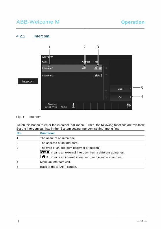
ABB-Welcome M Operation
| — 11 —
Pos: 30 /Di nA4 - A nleitu ngen Onlin e/Ueb ersc hrift en/3 ./Tuer oeff nen @ 2 0\mo d_1 323 263 277 453 _15. docx @ 11 193 5 @ 3 @ 1
4.2.2 IntercomPos: 31 /Di nA4 - A nleitu ngen Onlin e/In halt/KNX/Do orEnt ry/83 220 -AP-xxx/ Tue r o effne n - 832 20-AP-x xx @ 20\m od_ 132 326 795 847 9_15 .docx @ 1 121 09 @ @ 1
Fig. 4 Intercom
Touch this button to enter the intercom call menu . Then, the following functions are available.Set the intercom call lists in the “System setting-intercom setting“ menu first.No. Functions1 The name of an intercom.
2 The address of an intercom.
3 The type of an intercom (external or internal). means an external intercom from a different apartment. means an internal intercom from the same apartment.
4 Make an intercom call.
5 Back to the START screen.
4
1
Intercom
5
2 3
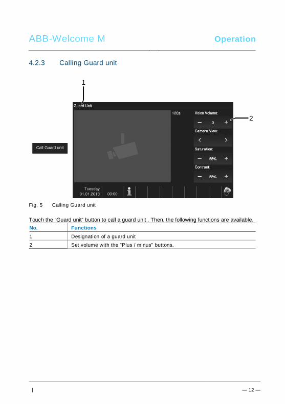
ABB-Welcome M Operation
| — 12 —
4.2.3 Calling Guard unitPos: 31 /Di nA4 - A nleitu ngen Onlin e/In halt/KNX/Do orEnt ry/83 220 -AP-xxx/ Tue r o effne n - 832 20-AP-x xx @ 20\m od_ 132 326 795 847 9_15 .docx @ 1 121 09 @ @ 1
Fig. 5 Calling Guard unit
Touch the “Guard unit“ button to call a guard unit . Then, the following functions are available.No. Functions1 Designation of a guard unit
2 Set volume with the "Plus / minus" buttons.
Call Guard unit
2
1
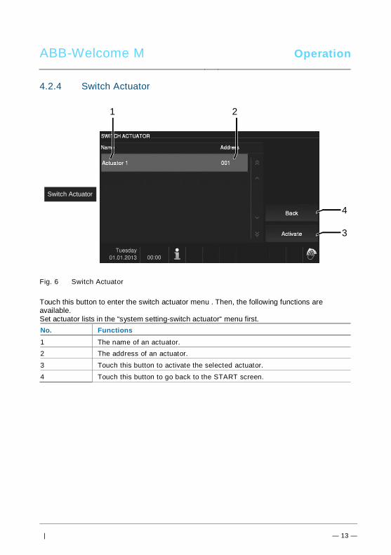
ABB-Welcome M Operation
| — 13 —
4.2.4 Switch ActuatorPos: 31 /Di nA4 - A nleitu ngen Onlin e/In halt/KNX/Do orEnt ry/83 220 -AP-xxx/ Tue r o effne n - 832 20-AP-x xx @ 20\m od_ 132 326 795 847 9_15 .docx @ 1 121 09 @ @ 1
Fig. 6 Switch Actuator
Touch this button to enter the switch actuator menu . Then, the following functions areavailable.Set actuator lists in the “system setting-switch actuator“ menu first.No. Functions1 The name of an actuator.2 The address of an actuator.
3 Touch this button to activate the selected actuator.
4 Touch this button to go back to the START screen.
Switch Actuator
4
1 2
3
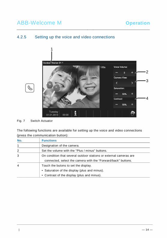
ABB-Welcome M Operation
| — 14 —
4.2.5 Setting up the voice and video connectionsPos: 31 /Di nA4 - A nleitu ngen Onlin e/In halt/KNX/Do orEnt ry/83 220 -AP-xxx/ Tue r o effne n - 832 20-AP-x xx @ 20\m od_ 132 326 795 847 9_15 .docx @ 1 121 09 @ @ 1
Fig. 7 Switch Actuator
The following functions are available for setting up the voice and video connections(press the communication button):No. Functions1 Designation of the camera.
2 Set the volume with the "Plus / minus" buttons.
3 On condition that several outdoor stations or external cameras areconnected, select the camera with the “Forward/back” buttons.
4 Touch the butons to set the display.• Saturation of the display (plus and minus).• Contrast of the display (plus and minus).
Pos: 29 /B usch-J aeg er (Neus truk tur )/M odul -Strukt ur/O nline -Doku me ntatio n/Steu er mod ule - Onlin e-Dok ume ntati on ( -- > Für alle Dok ume nte <- -)/ +++ ++ ++ +++ ++ S eiten umb ruch + +++ ++ ++ +++ + @ 9\m od_ 126 8898 668 093 _0. docx @ 521 49 @ @ 1
2
3
4
1
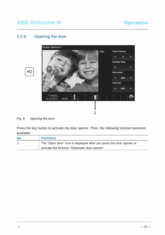
ABB-Welcome M Operation
| — 15 —
4.2.6 Opening the doorPos: 31 /Di nA4 - A nleitu ngen Onlin e/In halt/KNX/Do orEnt ry/83 220 -AP-xxx/ Tue r o effne n - 832 20-AP-x xx @ 20\m od_ 132 326 795 847 9_15 .docx @ 1 121 09 @ @ 1
Fig. 8 Opening the door
Press the key button to activate the door opener. Then, the following function becomesavailable:No. Functions1 The "Open door" icon is displayed after you press the door opener or
activate the function "Automatic door opener".
1
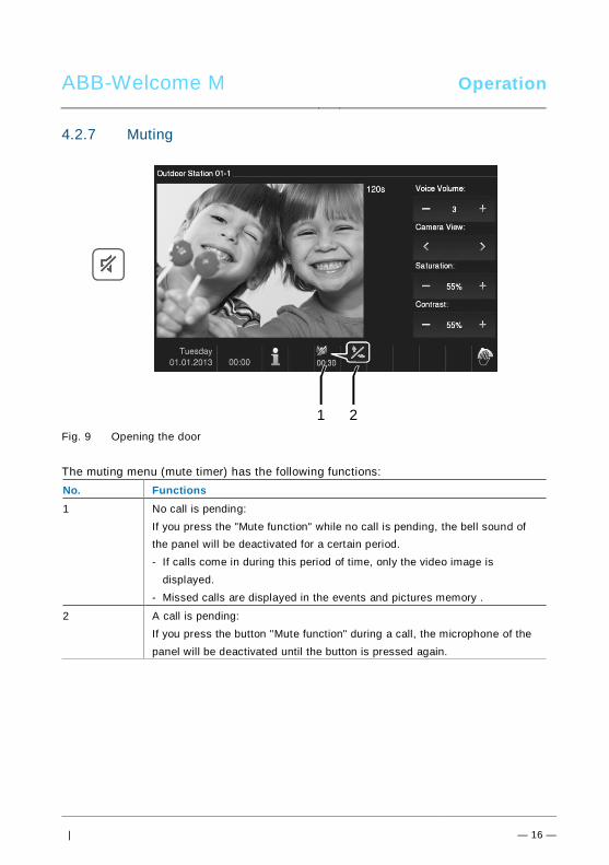
ABB-Welcome M Operation
| — 16 —
4.2.7 MutingPos: 31 /Di nA4 - A nleitu ngen Onlin e/In halt/KNX/Do orEnt ry/83 220 -AP-xxx/ Tue r o effne n - 832 20-AP-x xx @ 20\m od_ 132 326 795 847 9_15 .docx @ 1 121 09 @ @ 1
Fig. 9 Opening the door
The muting menu (mute timer) has the following functions:No. Functions1 No call is pending:
If you press the "Mute function" while no call is pending, the bell sound ofthe panel will be deactivated for a certain period.- If calls come in during this period of time, only the video image is
displayed.- Missed calls are displayed in the events and pictures memory .
2 A call is pending:If you press the button "Mute function" during a call, the microphone of thepanel will be deactivated until the button is pressed again.
1 2
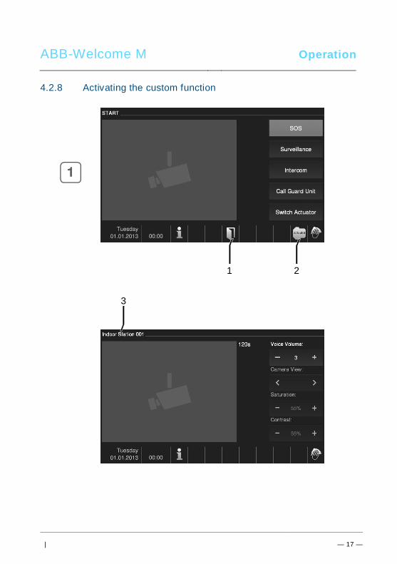
ABB-Welcome M Operation
| — 17 —
4.2.8 Activating the custom functionPos: 31 /Di nA4 - A nleitu ngen Onlin e/In halt/KNX/Do orEnt ry/83 220 -AP-xxx/ Tue r o effne n - 832 20-AP-x xx @ 20\m od_ 132 326 795 847 9_15 .docx @ 1 121 09 @ @ 1
1 2
3
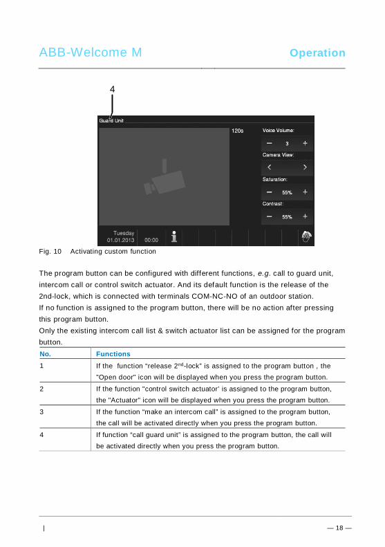
ABB-Welcome M Operation
| — 18 —
Fig. 10 Activating custom function
The program button can be configured with different functions , e.g. call to guard unit,intercom call or control switch actuator. And its default function is the release of the2nd-lock, which is connected with terminals COM-NC-NO of an outdoor station.If no function is assigned to the program button, there will be no action after pressingthis program button.Only the existing intercom call list & switch actuator list can be assigned for the programbutton.No. Functions1 If the function “release 2nd-lock” is assigned to the program button , the
"Open door" icon will be displayed when you press the program button.
2 If the function "control switch actuator’ is assigned to the program button,the "Actuator" icon will be displayed when you press the program button.
3 If the function “make an intercom call” is assigned to the program button,the call will be activated directly when you press the program button.
4 If function “call guard unit” is assigned to the program button, the call willbe activated directly when you press the program button.
4
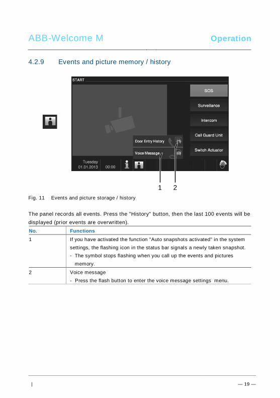
ABB-Welcome M Operation
| — 19 —
4.2.9 Events and picture memory / historyPos: 31 /Di nA4 - A nleitu ngen Onlin e/In halt/KNX/Do orEnt ry/83 220 -AP-xxx/ Tue r o effne n - 832 20-AP-x xx @ 20\m od_ 132 326 795 847 9_15 .docx @ 1 121 09 @ @ 1
Fig. 11 Events and picture storage / history
The panel records all events. Press the "History" button, then the last 100 events will bedisplayed (prior events are overwritten).No. Functions1 If you have activated the function "Auto snapshots activated" in the system
settings, the flashing icon in the status bar signals a newly taken snapshot.- The symbol stops flashing when you call up the events and pictures
memory.
2 Voice message- Press the flash button to enter the voice message settings menu.
1 2
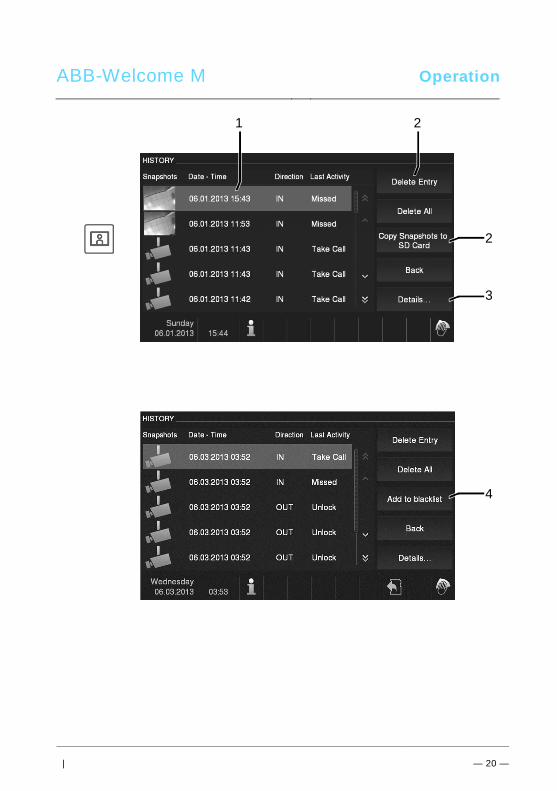
ABB-Welcome M Operation
| — 20 —
1 2
2
3
4
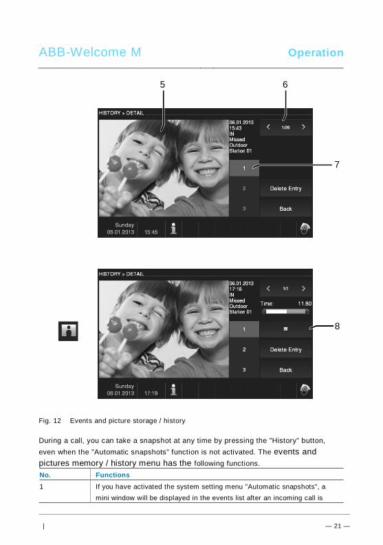
ABB-Welcome M Operation
| — 21 —
Fig. 12 Events and picture storage / history
During a call, you can take a snapshot at any time by pressing the "History" button,even when the "Automatic snapshots" function is not activated. The events andpictures memory / history menu has the following functions.No. Functions1 If you have activated the system setting menu "Automatic snapshots", a
mini window will be displayed in the events list after an incoming call is
8
5 6
7
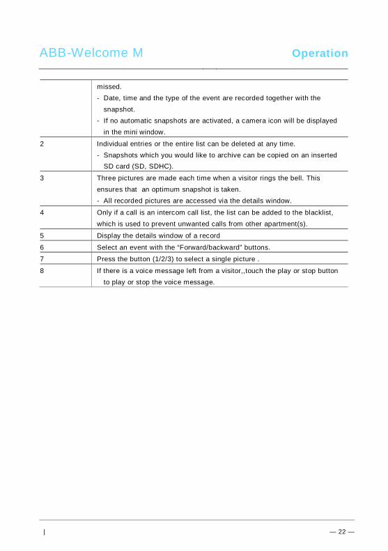
ABB-Welcome M Operation
| — 22 —
missed.- Date, time and the type of the event are recorded together with the
snapshot.- If no automatic snapshots are activated, a camera icon will be displayed
in the mini window.
2 Individual entries or the entire list can be deleted at any time.- Snapshots which you would like to archive can be copied on an inserted
SD card (SD, SDHC).
3 Three pictures are made each time when a visitor rings the bell. Thisensures that an optimum snapshot is taken.- All recorded pictures are accessed via the details window.
4 Only if a call is an intercom call list, the list can be added to the blacklist,which is used to prevent unwanted calls from other apartment(s).
5 Display the details window of a record
6 Select an event with the “Forward/backward” buttons.
7 Press the button (1/2/3) to select a single picture .
8 If there is a voice message left from a visitor,,touch the play or stop buttonto play or stop the voice message.
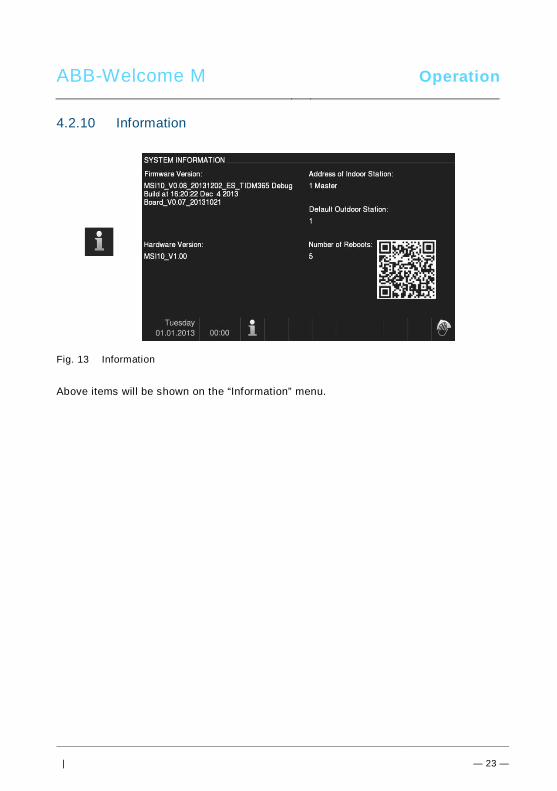
ABB-Welcome M Operation
| — 23 —
4.2.10 InformationPos: 31 /Di nA4 - A nleitu ngen Onlin e/In halt/KNX/Do orEnt ry/83 220 -AP-xxx/ Tue r o effne n - 832 20-AP-x xx @ 20\m od_ 132 326 795 847 9_15 .docx @ 1 121 09 @ @ 1
Fig. 13 Information
Above items will be shown on the “Information” menu.
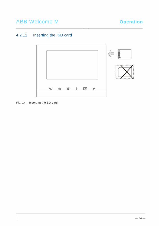
ABB-Welcome M Operation
| — 24 —
4.2.11 Inserting the SD cardPos: 31 /Di nA4 - A nleitu ngen Onlin e/In halt/KNX/Do orEnt ry/83 220 -AP-xxx/ Tue r o effne n - 832 20-AP-x xx @ 20\m od_ 132 326 795 847 9_15 .docx @ 1 121 09 @ @ 1
Fig. 14 Inserting the SD card
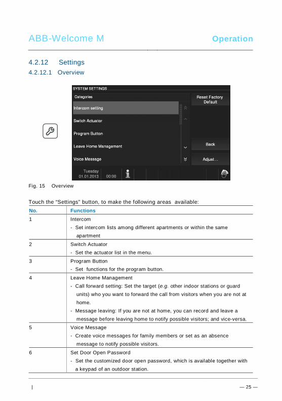
ABB-Welcome M Operation
| — 25 —
4.2.12 SettingsPos: 31 /Di nA4 - A nleitu ngen Onlin e/In halt/KNX/Do orEnt ry/83 220 -AP-xxx/ Tue r o effne n - 832 20-AP-x xx @ 20\m od_ 132 326 795 847 9_15 .docx @ 1 121 09 @ @ 1
4.2.12.1 Overview
Fig. 15 Overview
Touch the “Settings” button, to make the following areas available:No. Functions1 Intercom
- Set intercom lists among different apartments or within the sameapartment
2 Switch Actuator- Set the actuator list in the menu.
3 Program Button- Set functions for the program button.
4 Leave Home Management- Call forward setting: Set the target (e.g. other indoor stations or guard
units) who you want to forward the call from visitors when you are not athome.
- Message leaving: If you are not at home, you can record and leave amessage before leaving home to notify possible visitors; and vice-versa.
5 Voice Message- Create voice messages for family members or set as an absence
message to notify possible visitors.
6 Set Door Open Password- Set the customized door open password, which is available together with
a keypad of an outdoor station.
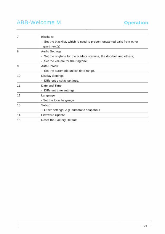
ABB-Welcome M Operation
| — 26 —
7 BlackList- Set the blacklist, which is used to prevent unwanted calls from otherapartment(s)
8 Audio Settings- Set the ringtone for the outdoor stations, the doorbell and others;- Set the volume for the ringtone
9 Auto Unlock- Set the automatic unlock time range.
10 Display Settings- Different display settings.
11 Date and Time- Different time settings
12 Language- Set the local language
13 Set-up- Other settings, e.g. automatic snapshots
14 Firmware Update
15 Reset the Factory Default

ABB-Welcome M Operation
| — 27 —
Fig. 16 Overview of settings
To turn to the setting areas of the list field (1), carry out the following steps:No. Function1 To display the hidden functions, click on the scroll buttons (2).
2 Touch one of the setting areas.
3 Touch the button "Set" (3).- The device turns to the selected settings area.- The individual functions are described in the following chapters.- The device turns back to the start page when pressing the button "Back".
4 By tipping on this button you back to the start page.
4
1 2
3
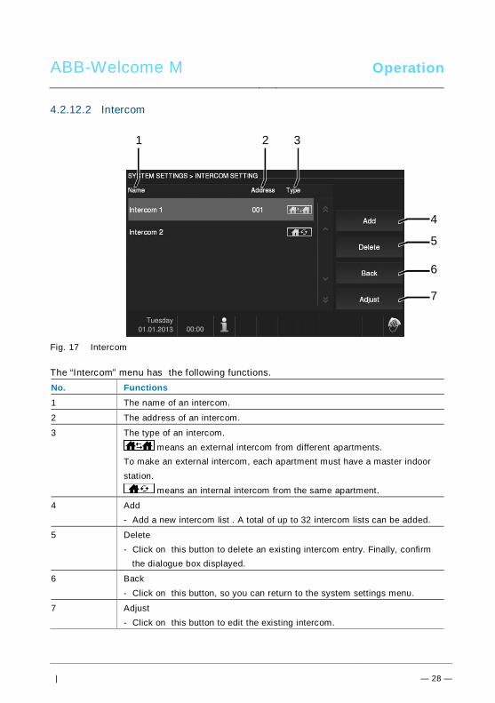
ABB-Welcome M Operation
| — 28 —
4.2.12.2 Intercom
Fig. 17 Intercom
The “Intercom” menu has the following functions.No. Functions1 The name of an intercom.
2 The address of an intercom.
3 The type of an intercom. means an external intercom from different apartments.
To make an external intercom, each apartment must have a master indoorstation.
means an internal intercom from the same apartment.
4 Add- Add a new intercom list . A total of up to 32 intercom lists can be added.
5 Delete- Click on this button to delete an existing intercom entry. Finally, confirm
the dialogue box displayed.
6 Back- Click on this button, so you can return to the system settings menu.
7 Adjust- Click on this button to edit the existing intercom.
4
5
1 32
6
7
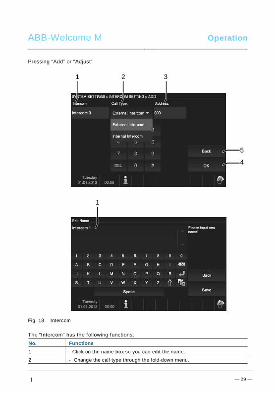
ABB-Welcome M Operation
| — 29 —
Pressing “Add” or “Adjust”
Fig. 18 Intercom
The “Intercom” has the following functions:No. Functions1 - Click on the name box so you can edit the name.
2 - Change the call type through the fold-down menu.
5
4
1 32
1
ABB-Welcome M Operation
| — 30 —
*External intercom” means a call from different apartments*Internal intercom” means a call from the same apartment
3 - Edit the address via the numeric keyboard, from 001 to 250.*If the call is an internal intercom, there is no need to set the target
address.
4 - Touch the “OK” button to activate the settings.
5 - Touch the “Back” button, so you can return to the “ Intercom settings”menu without saving the settings.
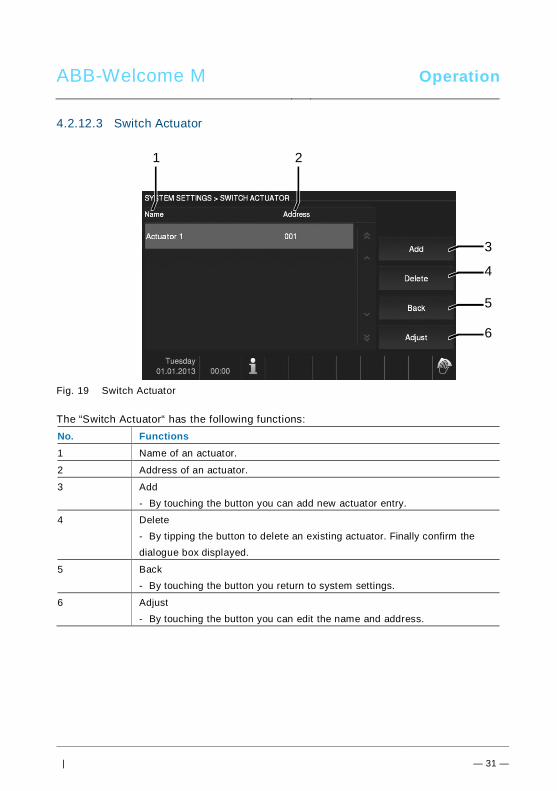
ABB-Welcome M Operation
| — 31 —
4.2.12.3 Switch Actuator
Fig. 19 Switch Actuator
The “Switch Actuator“ has the following functions:No. Functions1 Name of an actuator.
2 Address of an actuator.
3 Add- By touching the button you can add new actuator entry.
4 Delete- By tipping the button to delete an existing actuator. Finally confirm thedialogue box displayed.
5 Back- By touching the button you return to system settings.
6 Adjust- By touching the button you can edit the name and address.
3
4
1 2
5
6
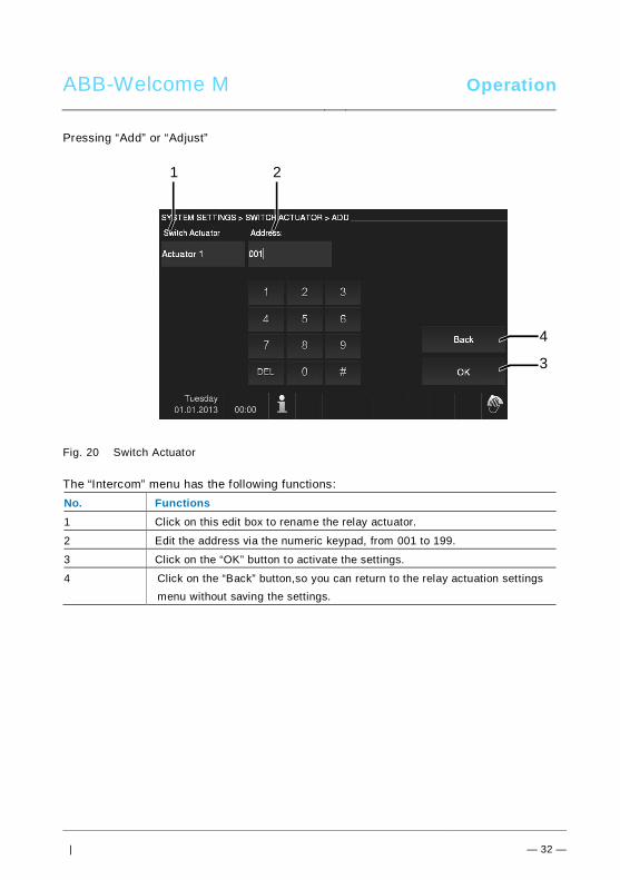
ABB-Welcome M Operation
| — 32 —
Pressing “Add” or “Adjust”
Fig. 20 Switch Actuator
The “Intercom” menu has the following functions:No. Functions1 Click on this edit box to rename the relay actuator.
2 Edit the address via the numeric keypad, from 001 to 199.
3 Click on the “OK” button to activate the settings.
4 Click on the “Back” button,so you can return to the relay actuation settingsmenu without saving the settings.
4
3
1 2
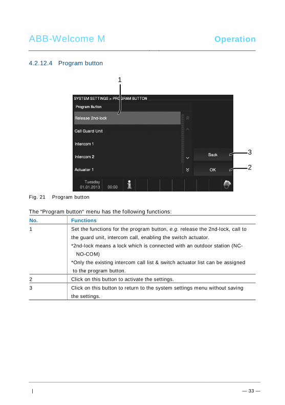
ABB-Welcome M Operation
| — 33 —
4.2.12.4 Program button
Fig. 21 Program button
The “Program button“ menu has the following functions:No. Functions1 Set the functions for the program button, e.g. release the 2nd-lock, call to
the guard unit, intercom call, enabling the switch actuator.*2nd-lock means a lock which is connected with an outdoor station (NC-
NO-COM)*Only the existing intercom call list & switch actuator list can be assigned to the program button.
2 Click on this button to activate the settings.
3 Click on this button to return to the system settings menu without savingthe settings.
3
2
1
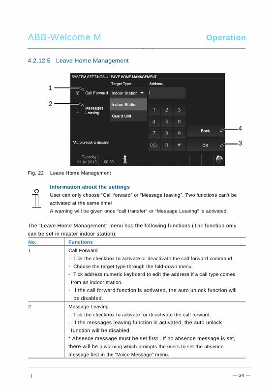
ABB-Welcome M Operation
| — 34 —
4.2.12.5 Leave Home Management
Fig. 22 Leave Home Management
Information about the settingsUser can only choose “Call forward” or “Message leaving”. Two functions can’t beactivated at the same time!A warning will be given once “call transfer” or “Message Leaving” is activated.
The “Leave Home Management” menu has the following functions (The function onlycan be set in master indoor station):No. Functions1 Call Forward
- Tick the checkbox to activate or deactivate the call forward command.- Choose the target type through the fold-down menu.- Tick address numeric keyboard to edit the address if a call type comesfrom an indoor station.
- If the call forward function is activated, the auto unlock function willbe disabled.
2 Message Leaving- Tick the checkbox to activate or deactivate the call forward.- If the messages leaving function is activated, the auto unlockfunction will be disabled.
* Absence message must be set first . If no absence message is set,there will be a warning which prompts the users to set the absencemessage first in the “Voice Message” menu.
4
3
1
2
ABB-Welcome M Operation
| — 35 —
3 OK- Touch this button to activate the settings.
4 Back- Touch this button to return to the system settings menu without savingthe settings.
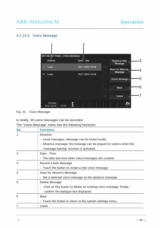
ABB-Welcome M Operation
| — 36 —
4.2.12.6 Voice Message
Fig. 23 Voice Message
In totally, 30 voice messages can be recorded.The “Voice Message” menu has the following functions:No. Functions1 Direction
- Local messages: Message can be heard locally- Absence message: the message can be played for visitors when the
“message leaving” function is activated.
2 Date - Time- The date and time when voice messages are created.
3 Record a New Message- Touch the button to create a new voice message.
4 Save for Absence Message- Set a selected voice message as the absence message
5 Delete Message- Click on this button to delete an existing voice message. Finally,
confirm the dialogue box displayed.
6 Back- Touch the button to return to the system settings menu..
7 Listen
6
7
1 2
3
4
5
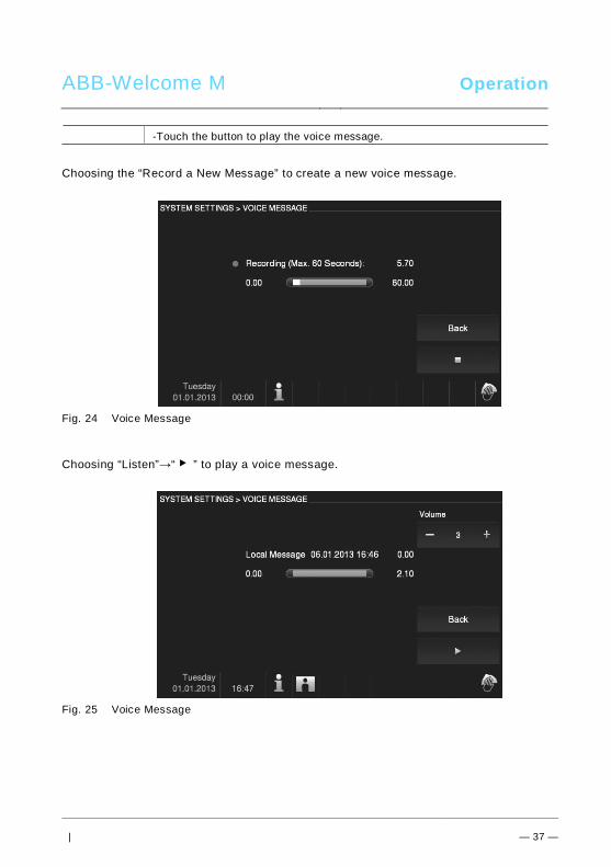
ABB-Welcome M Operation
| — 37 —
-Touch the button to play the voice message.
Choosing the “Record a New Message” to create a new voice message.
Fig. 24 Voice Message
Choosing “Listen”→“ ▶ ” to play a voice message.
Fig. 25 Voice Message
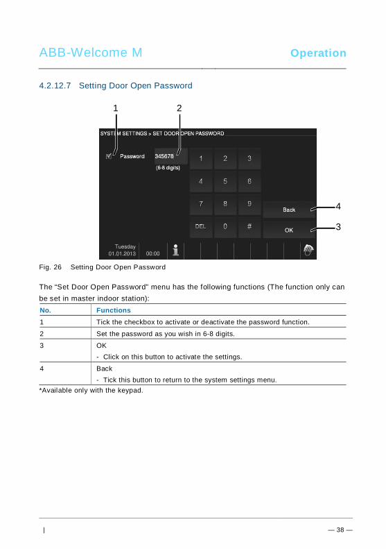
ABB-Welcome M Operation
| — 38 —
4.2.12.7 Setting Door Open Password
Fig. 26 Setting Door Open Password
The “Set Door Open Password” menu has the following functions (The function only canbe set in master indoor station):No. Functions1 Tick the checkbox to activate or deactivate the password function.
2 Set the password as you wish in 6-8 digits.
3 OK- Click on this button to activate the settings.
4 Back- Tick this button to return to the system settings menu.
*Available only with the keypad.
4
3
21
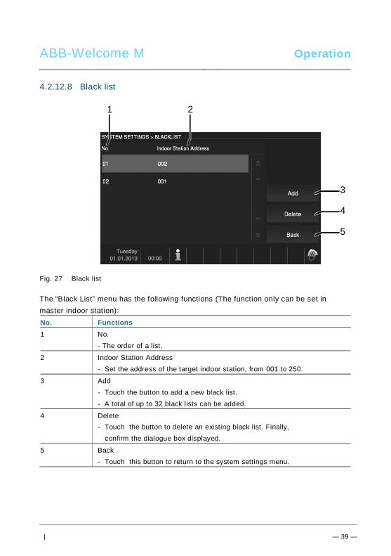
ABB-Welcome M Operation
| — 39 —
4.2.12.8 Black list
Fig. 27 Black list
The “Black List” menu has the following functions (The function only can be set inmaster indoor station):No. Functions1 No.
- The order of a list.
2 Indoor Station Address- Set the address of the target indoor station, from 001 to 250.
3 Add- Touch the button to add a new black list.- A total of up to 32 black lists can be added.
4 Delete- Touch the button to delete an existing black list. Finally,
confirm the dialogue box displayed.
5 Back- Touch this button to return to the system settings menu.
4
5
1 2
3
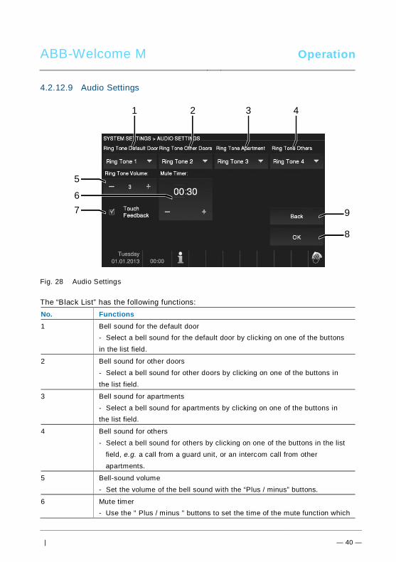
ABB-Welcome M Operation
| — 40 —
4.2.12.9 Audio Settings
Fig. 28 Audio Settings
The “Black List” has the following functions:No. Functions1 Bell sound for the default door
- Select a bell sound for the default door by clicking on one of the buttonsin the list field.
2 Bell sound for other doors- Select a bell sound for other doors by clicking on one of the buttons inthe list field.
3 Bell sound for apartments- Select a bell sound for apartments by clicking on one of the buttons inthe list field.
4 Bell sound for others- Select a bell sound for others by clicking on one of the buttons in the list
field, e.g. a call from a guard unit, or an intercom call from otherapartments.
5 Bell-sound volume- Set the volume of the bell sound with the “Plus / minus” buttons.
6 Mute timer- Use the " Plus / minus " buttons to set the time of the mute function which
9
8
1 2
5
3 4
67
ABB-Welcome M Operation
| — 41 —
you activate with the "mute" button.- Before adjusting the "Hours" or "Minutes", the active range is highlighted
with a frame.
7 Touch Feedback- Tick the checkbox to activate or deactivate the feedback tone whichsounds when the display or the button is touched.
8 OK- Touch this button to activate the settings.
9 Back- Touch this button to return to the system settings menu.
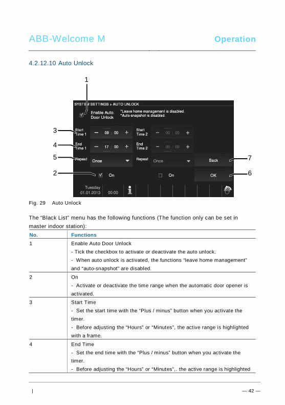
ABB-Welcome M Operation
| — 42 —
4.2.12.10 Auto Unlock
Fig. 29 Auto Unlock
The “Black List” menu has the following functions (The function only can be set inmaster indoor station):No. Functions1 Enable Auto Door Unlock
- Tick the checkbox to activate or deactivate the auto unlock.- When auto unlock is activated, the functions “leave home management”and “auto-snapshot” are disabled.
2 On- Activate or deactivate the time range when the automatic door opener isactivated.
3 Start Time- Set the start time with the “Plus / minus” button when you activate thetimer.- Before adjusting the “Hours” or “Minutes”, the active range is highlightedwith a frame.
4 End Time- Set the end time with the “Plus / minus” button when you activate thetimer.- Before adjusting the “Hours” or “Minutes”,. the active range is highlighted
7
6
3
1
4
5
2
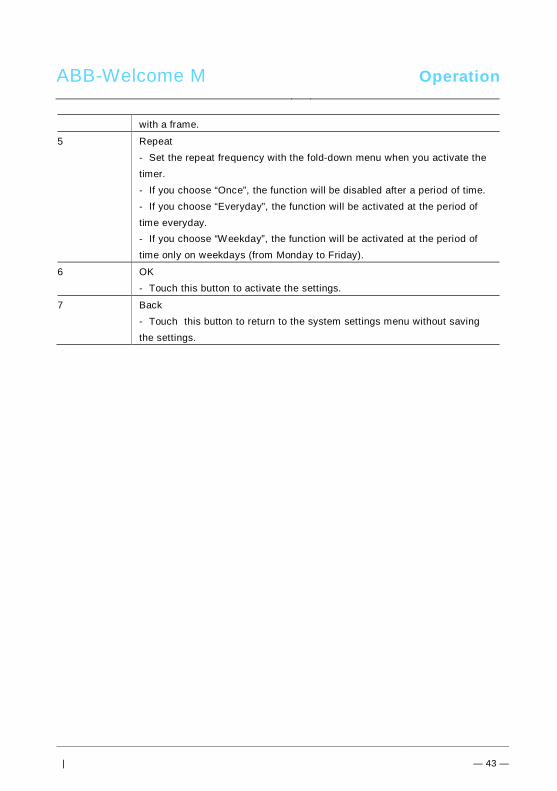
ABB-Welcome M Operation
| — 43 —
with a frame.
5 Repeat- Set the repeat frequency with the fold-down menu when you activate thetimer.- If you choose “Once”, the function will be disabled after a period of time.- If you choose “Everyday”, the function will be activated at the period oftime everyday.- If you choose “Weekday”, the function will be activated at the period oftime only on weekdays (from Monday to Friday).
6 OK- Touch this button to activate the settings.
7 Back- Touch this button to return to the system settings menu without savingthe settings.
Pos: 32 /B usch-J aeg er (Neus truk tur )/M odul -Strukt ur/O nline -Doku me ntatio n/Steu er mod ule - Onlin e-Dok ume ntati on ( -- > Für alle Dok ume nte <- -)/ +++ ++ ++ +++ ++ S eiten umb ruch + +++ ++ ++ +++ + @ 9\m od_ 126 8898 668 093 _0. docx @ 521 49 @ @ 1
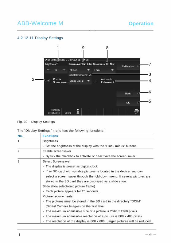
ABB-Welcome M Operation
| — 44 —
4.2.12.11 Display Settings
Fig. 30 Display Settings
The "Display Settings" menu has the following functions:No. Functions1 Brightness
- Set the brightness of the display with the "Plus / minus" buttons.
2 Enable screensaver- By tick the checkbox to activate or deactivate the screen saver.
3 Select Screensaver- The display is preset as digital clock- If an SD card with suitable pictures is located in the device, you can
select a screen saver through the fold-down menu. If several pictures arestored in the SD card they are displayed as a slide show.
Slide show (electronic picture frame)- Each picture appears for 20 seconds.Picture requirements:- The pictures must be stored in the SD card in the directory "DCIM"
(Digital Camera Images) on the first level.- The maximum admissible size of a picture is 2048 x 1960 pixels.- The maximum admissible resolution of a picture is 800 x 480 pixels.- The resolution of the display is 800 x 600. Larger pictures will be reduced
6
5
1 9 8
7
234
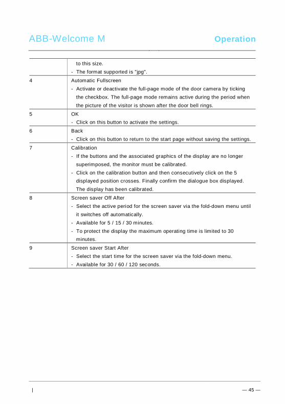
ABB-Welcome M Operation
| — 45 —
to this size.- The format supported is "jpg".
4 Automatic Fullscreen- Activate or deactivate the full-page mode of the door camera by ticking
the checkbox. The full-page mode remains active during the period whenthe picture of the visitor is shown after the door bell rings.
5 OK- Click on this button to activate the settings.
6 Back- Click on this button to return to the start page without saving the settings.
7 Calibration- If the buttons and the associated graphics of the display are no longer
superimposed, the monitor must be calibrated.- Click on the calibration button and then consecutively click on the 5
displayed position crosses. Finally confirm the dialogue box displayed. The display has been calibrated.
8 Screen saver Off After- Select the active period for the screen saver via the fold-down menu until
it switches off automatically.- Available for 5 / 15 / 30 minutes.- To protect the display the maximum operating time is limited to 30
minutes.
9 Screen saver Start After- Select the start time for the screen saver via the fold-down menu.- Available for 30 / 60 / 120 seconds.
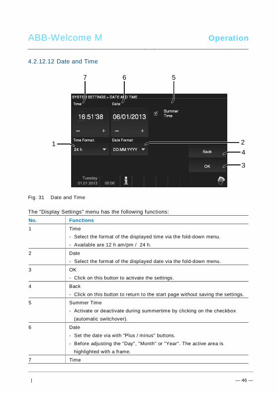
ABB-Welcome M Operation
| — 46 —
4.2.12.12 Date and Time
Fig. 31 Date and Time
The "Display Settings" menu has the following functions:No. Functions1 Time
- Select the format of the displayed time via the fold-down menu.- Available are 12 h am/pm / 24 h.
2 Date- Select the format of the displayed date via the fold-down menu.
3 OK- Click on this button to activate the settings.
4 Back- Click on this button to return to the start page without saving the settings.
5 Summer Time- Activate or deactivate during summertime by clicking on the checkbox
(automatic switchover).
6 Date- Set the date via with "Plus / minus" buttons.- Before adjusting the "Day", "Month" or "Year". The active area is
highlighted with a frame.
7 Time
4
3
7 6 5
1 2
ABB-Welcome M Operation
| — 47 —
- Set the time with the "Plus / minus" buttons.- Before adjusting the "Hours", "Minutes" or "Seconds", the active area is
highlighted with a frame.

ABB-Welcome M Operation
| — 48 —
4.2.12.13 Language
Fig. 32 Language
The "Language" menu has the following functions:No. Functions1 Language (list field)
- Here the languages available are listed
2 Scroll- To display the hidden languages, tick the scroll boxes.
3 OKTick this button to activate the settings.
4 Back- Tick this button to return to the start page without saving the settings.
4
3
1 2
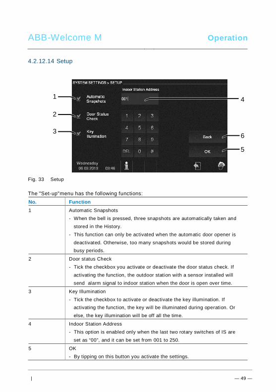
ABB-Welcome M Operation
| — 49 —
4.2.12.14 Setup
Fig. 33 Setup
The "Set-up"menu has the following functions:No. Function1 Automatic Snapshots
- When the bell is pressed, three snapshots are automatically taken andstored in the History.
- This function can only be activated when the automatic door opener isdeactivated. Otherwise, too many snapshots would be stored duringbusy periods.
2 Door status Check- Tick the checkbox you activate or deactivate the door status check. If
activating the function, the outdoor station with a sensor installed willsend alarm signal to indoor station when the door is open over time.
3 Key Illumination- Tick the checkbox to activate or deactivate the key illumination. If
activating the function, the key will be illuminated during operation. Orelse, the key illumination will be off all the time.
4 Indoor Station Address- This option is enabled only when the last two rotary switches of IS are
set as “00”, and it can be set from 001 to 250.
5 OK- By tipping on this button you activate the settings.
6
5
1
2
3
4
ABB-Welcome M Operation
| — 50 —
6 Back- By tipping on this button you return to the start page without saving the
settings.
ABB-Welcome M Operation
| — 51 —
4.2.12.15 Firmware Update
If the firmware for your device is to be updated, carry out the following steps:1. Get the new version of firmware from your electrical installer, and copy it into a SD-
card.2. Insert the SD-card into the card slot on your indoor station.3. Select “Firmware Update”4. Execute the firmware updated by selecting “Updating”5. Confirm the popup with “yes”.Pos: 67 /Di nA4 - A nleitu ngen Onlin e/Ueb ersc hrift en/2 ./Reini gung @ 1 9\m od_ 131 0733 980 533 _15. docx @ 10 785 3 @ 2 @ 1
ABB-Welcome M Operation
| — 52 —
4.3 CleaningPos: 68 /Di nA4 - A nleitu ngen Onlin e/In halt/KNX/Do orEnt ry/Reini gun g/Reini gun g Touchsc ree nm onito r @ 19\m od_ 131 073 410 897 8_15 .docx @ 1 078 62 @ @ 1
CautionRisk of damage to the screen surface.The screen surface can be damaged by hard or sharp objects!Never use such objects for entries on the touch screen monitor.- Use your finger or a plastic stylus.
The screen surface can be damaged by cleaning fluids or abrasiveagents!- Clean the surfaces using a soft cloth and commercially available
glass cleaner.- Never use abrasive cleaning agents.
Pos: 69 /B usch-J aeg er (Neus truk tur )/M odul -Strukt ur/O nline -Doku me ntatio n/Steu er mod ule - Onlin e-Dok ume ntati on ( -- > Für alle Dok ume nte <- -)/ +++ ++ ++ +++ ++ S eiten umb ruch + +++ ++ ++ +++ + @ 9\m od_ 126 8898 668 093 _0. docx @ 521 49 @ @ 1
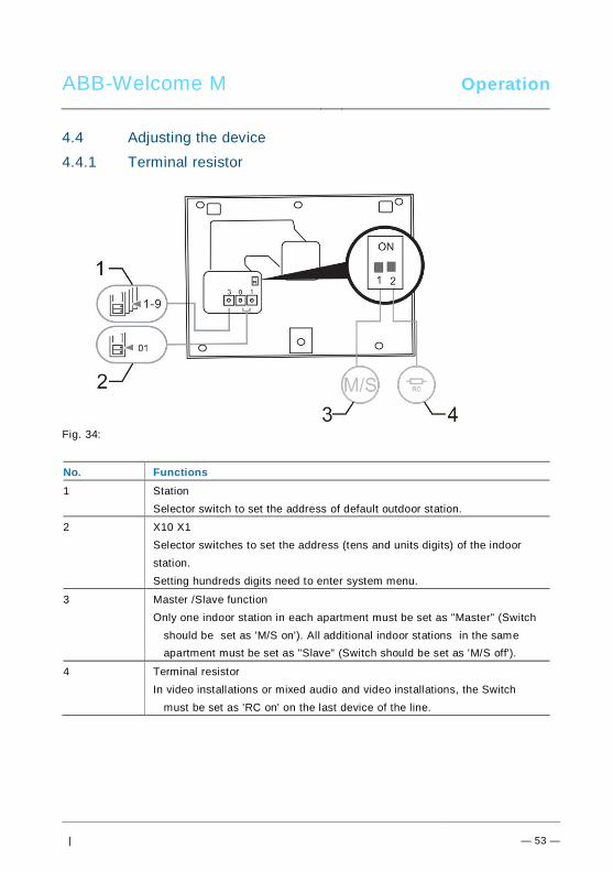
ABB-Welcome M Operation
| — 53 —
Pos: 70 /Di nA4 - A nleitu ngen Onlin e/Ueb ersc hrift en/2 ./Ge raet eeins tellun gen @ 1 8\mo d_1 302 768 847 744 _15. docx @ 10 354 8 @ 2 @ 1
4.4 Adjusting the devicePos: 71 /Di nA4 - A nleitu ngen Onlin e/Ueb ersc hrift en/3 ./Abschl usswide rsta nd @ 19\ mod _13 219 5807 990 6_1 5.do cx @ 1100 83 @ 3 @ 1
Pos: 72 /Di nA4 - A nleitu ngen Onlin e/In halt/KNX/Do orEnt ry/Bedie nun g/Abschl usswide rsta nd s etzen 83 220 -AP-xxx @ 19\ mod _13 1072 339 236 9_1 5.do cx @ 1 078 41 @ @ 1
4.4.1 Terminal resistor
Fig. 34:Pos: 74 /Di nA4 - A nleitu ngen Onlin e/In halt/KNX/Do orEnt ry/Bedie nun g/M aste r/Slave Sc halte r setz en 832 20-AP-xxx @ 1 9\m od_1 310 723 320 966 _15. docx @ 10 783 3 @ @
No. Functions1 Station
Selector switch to set the address of default outdoor station.
2 X10 X1Selector switches to set the address (tens and units digits) of the indoorstation.Setting hundreds digits need to enter system menu.
3 Master /Slave functionOnly one indoor station in each apartment must be set as "Master" (Switch
should be set as 'M/S on'). All additional indoor stations in the sameapartment must be set as "Slave" (Switch should be set as 'M/S off').
4 Terminal resistorIn video installations or mixed audio and video installations, the Switch
must be set as 'RC on' on the last device of the line.
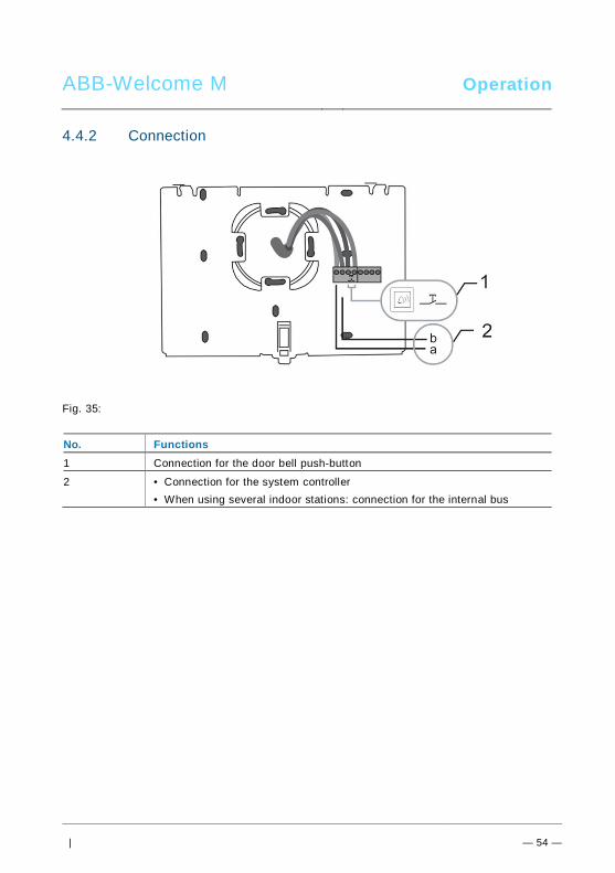
ABB-Welcome M Operation
| — 54 —
4.4.2 Connection
Fig. 35:
No. Functions1 Connection for the door bell push-button
2 • Connection for the system controller• When using several indoor stations: connection for the internal bus
Pos: 75 /B usch-J aeg er (Neus truk tur )/M odul -Strukt ur/O nline -Doku me ntatio n/Steu er mod ule - Onlin e-Dok ume ntati on ( -- > Für alle Dok ume nte <- -)/ +++ ++ ++ +++ ++ S eiten umb ruch + +++ ++ ++ +++ + @ 9\m od_ 126 8898 668 093 _0. docx @ 521 49 @ @ 1
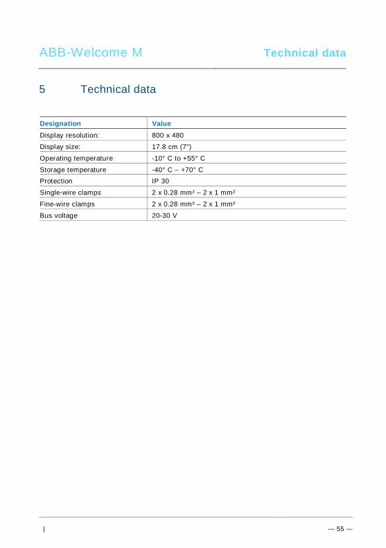
ABB-Welcome M Technical data
| — 55 —
Pos: 76 /Di nA4 - A nleitu ngen Onlin e/Ueb ersc hrift en/1 ./Technisc he D aten @ 18 \mo d_1 302 615 863 001 _15. docx @ 10 341 6 @ 1 @ 1
5 Technical dataPos: 77 /Di nA4 - A nleitu ngen Onlin e/In halt/KNX/Do orEnt ry/83 220 -AP-xxx/ Tech nische Date n - 832 20-AP-x xx @ 1 8\m od_ 130 321 285 4559 _15 .docx @ 1 037 05 @ @ 1
Designation ValueDisplay resolution: 800 x 480
Display size: 17.8 cm (7")
Operating temperature -10° C to +55° C
Storage temperature -40° C – +70° CProtection IP 30
Single-wire clamps 2 x 0.28 mm² – 2 x 1 mm²
Fine-wire clamps 2 x 0.28 mm² – 2 x 1 mm²
Bus voltage 20-30 V
Pos: 78 /B usch-J aeg er (Neus truk tur )/M odul -Strukt ur/O nline -Doku me ntatio n/Steu er mod ule - Onlin e-Dok ume ntati on ( -- > Für alle Dok ume nte <- -)/ +++ ++ ++ +++ ++ S eiten umb ruch + +++ ++ ++ +++ + @ 9\m od_ 126 8898 668 093 _0. docx @ 521 49 @ @ 1
ABB-Welcome M Mounting / Installation
| — 56 —
Pos: 79 /B usch-J aeg er (Neus truk tur )/M odul -Strukt ur/O nline -Doku me ntatio n/Übe rsch rifte n ( --> Fü r alle Doku men te < -- )/1. E bene /M - O/ Mont age / Ins tallatio n @ 18\ mod _13 0261 396 611 1_1 5.do cx @ 1 033 73 @ 1 @ 1
6 Mounting / InstallationPos: 80 /B usch-J aeg er (Neus truk tur )/M odul -Strukt ur/O nline -Doku me ntatio n/Siche rheit (- -> Fü r alle D oku ment e < --) /War nhinweis e/Siche rheit - Nie ders pan nun gs- und 230 V-Leit ung en @ 18\ mod _13 026 178 214 91_1 5.d ocx @ 103 465 @ @ 1
WarningElectric voltage!Risk of death and fire due to electrical voltage of 100-240 V.– Low-voltage and 100-240 V cables must not be installed together in
a flush-mounted socket!In case of a short-circuit there is the danger of a 100-240 V load onthe low-voltage line.
Pos: 81 /B usch-J aeg er (Neus truk tur )/M odul -Strukt ur/O nline -Doku me ntatio n/Siche rheit (- -> Fü r alle D oku ment e < --) /War nhinweis e/Siche rheit - Fachk enn tnisse @ 18 \mo d_1 302 774 384 017_ 15. docx @ 10 356 4 @ 2 @ 1
6.1 Requirements for the electrician
WarningElectric voltage!Install the device only if you have the necessary electrical engineeringknowledge and experience.• Incorrect installation endangers your life and that of the user of the
electrical system.• Incorrect installation can cause serious damage to property, e.g.
due to fire.The minimum necessary expert knowledge and requirements for the
installation are as follows:• Apply the "five safety rules" (DIN VDE 0105, EN 50110):
1. Disconnect from power;2. Secure against being re-connected;3. Ensure there is no voltage;4. Connect to earth;5. Cover or barricade adjacent live parts.
• Use suitable personal protective clothing.• Use only suitable tools and measuring devices.• Check the type supply network (TN system, IT system, TT system)
to secure the following power supply conditions (classic connectionto ground, protective earthing, necessary additional measures,etc.).
Pos: 82 /Di nA4 - A nleitu ngen Onlin e/In halt/KNX/Do orEnt ry/M onta ge/ Mont age hinweis e - Allg emei n @ 1 9\m od_ 131 056 367 047 8_15 .docx @ 1 077 43 @ 2 @ 1
ABB-Welcome M Mounting / Installation
| — 57 —
6.2 General installation instructions• Terminate all branches of the wiring system via a connected bus device (e.g.,
indoor station, outdoor station, system device).• Do not install the system controller directly next to the bell transformer and other
power supplies (to avoid interference).• Do not install the wires of the system bus together with 100-240 V wires.• Do not use common cables for the connecting wires of the door openers and wires
of the system bus.• Avoid bridges between different cable types.• Use only two wires for the system bus in a four-core or multi-core cable.• When looping, never install the incoming and outgoing bus inside the same cable.• Never install the internal and external bus inside the same cable.Pos: 83 /B usch-J aeg er (Neus truk tur )/M odul -Strukt ur/O nline -Doku me ntatio n/Steu er mod ule - Onlin e-Dok ume ntati on ( -- > Für alle Dok ume nte <- -)/ +++ ++ ++ +++ ++ S eiten umb ruch + +++ ++ ++ +++ + @ 9\m od_ 126 8898 668 093 _0. docx @ 521 49 @ @ 1
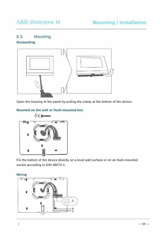
ABB-Welcome M Mounting / Installation
| — 58 —
Pos: 84 /B usch-J aeg er (Neus truk tur )/M odul -Strukt ur/O nline -Doku me ntatio n/Übe rsch rifte n ( --> Fü r alle Doku men te < -- )/2. E bene /M - O/ Mont age @ 1 8\m od_1 302 615 960 458 _15. docx @ 10 342 4 @ 2 @ 1
6.3 MountingPos: 85. 1 /DinA4 - Anleit ung en O nline/I nhal t/KNX/DoorE ntry/ 832 20-AP-xxx /Mo nta ge - Mo dule/ Mon tag e - Mon tage dos e -- 83 220 -AP-xxx @ 19\ mod _132 325 040 684 8_1 5.doc x @ 1 110 98 @ @ 1
Dismantling
Open the housing of the panel by pulling the clamp at the bottom of the device.
Mounted on the wall or flush-mounted box
Fix the bottom of the device directly on a level wall surface or on an flush-mountedsocket according to DIN 49073-1.
Wiring
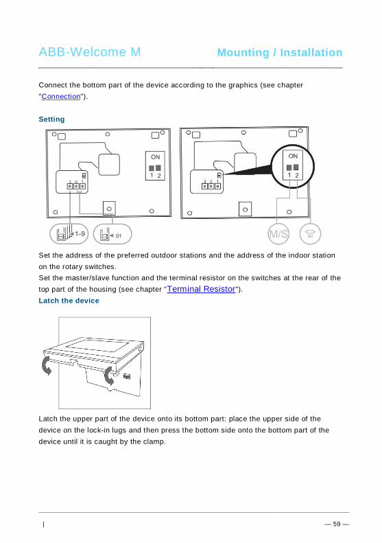
ABB-Welcome M Mounting / Installation
| — 59 —
Connect the bottom part of the device according to the graphics (see chapter"Connection").
Setting
Set the address of the preferred outdoor stations and the address of the indoor stationon the rotary switches.Set the master/slave function and the terminal resistor on the switches at the rear of thetop part of the housing (see chapter "Terminal Resistor").Latch the device
Latch the upper part of the device onto its bottom part: place the upper side of thedevice on the lock-in lugs and then press the bottom side onto the bottom part of thedevice until it is caught by the clamp.
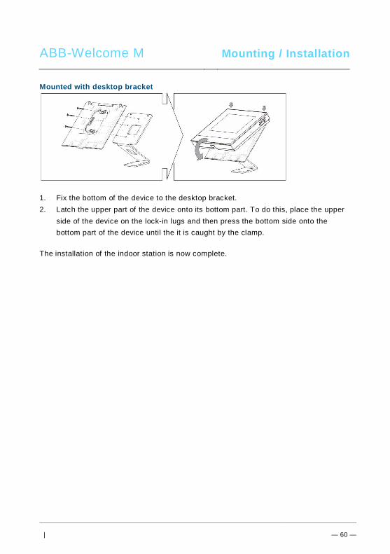
ABB-Welcome M Mounting / Installation
| — 60 —
Mounted with desktop bracket
1. Fix the bottom of the device to the desktop bracket.2. Latch the upper part of the device onto its bottom part. To do this, place the upper
side of the device on the lock-in lugs and then press the bottom side onto thebottom part of the device until the it is caught by the clamp.
The installation of the indoor station is now complete.
Pos: 94 /B usch-J aeg er (Neus truk tur )/M odul -Strukt ur/O nline -Doku me ntatio n/Steu er mod ule - Onlin e-Dok ume ntati on ( -- > Für alle Dok ume nte <- -)/ +++ ++ ++ +++ ++ S eiten umb ruch + +++ ++ ++ +++ + @ 9\m od_ 126 8898 668 093 _0. docx @ 521 49 @ @ 1
ABB-Welcome M Mounting / Installation
Pos: 95 /Di nA4 - A nleitu ngen Onlin e/In halt/KNX/Do orEnt ry/Proj ektier ung -M erkbl att/Pr ojektie rPos: 9 7 /Busc h-Ja ege r (N eust ruktu r)/ Mo dul-Str uktu r/Onli ne-D oku ment ation /Rückseit en (-- > Für alle Dok um ente <- -)/R ückseit e - Bus ch-J aeg er - Allgem ein @ 20\ mod _13 273 200 748 86_1 5.d ocx @ 137 103 @ @ 1
Notice=== E nde der Liste für Tex tma rke Ba ckcove r = ==
We reserve the right to at all times make technical changes as well as changes to thecontents of this document without prior notice.The detailed specifications agreed to at the time of ordering apply to all orders. ABBaccepts no responsibility for possible errors or incompleteness in this document. We reserve all rights to this document and the topics and illustrations contained therein.The document and its contents, or extracts thereof, must not be reproduced, transmittedor reused by third parties without prior written consent by ABB.
VER:1.0 │ 02.06.2014
ABB-Welcome M
Pos: 2 /DinA4 - Anl eitun gen Online /Inh alt/KNX/Doo rEntry /832 20-AP- xxx/Tit elblat t - 832 20-AP-xxx - ABB @ 1 9\m od_ 132 3249 806 476 _15. docx @ 11 108 4 @ @ 1
WM1701
WM3701
Moniteur intérieurmains libres avec écranvidéo 7"
=== E nde der Liste für Tex tma rke C over == =
ABB-Welcome M Ecran 7’’
— 2 —
Pos: 4 /Busc h-Ja ege r (N eust rukt ur)/ Mo dul-St ruktu r/Onli ne-D oku ment ation /Inh altsve rzeich nis ( --> Fü r alle Doku men te <-- )/In haltsve rzeic hnis @ 19\ mod _13 206 490 4438 6_1 5.d ocx @ 109 653 @ @ 1
1 Sécurité .................................................................................................... 32 Usage prévu ............................................................................................. 33 Environnement .......................................................................................... 4
3.1 Appareils ABB ........................................................................... 44 Fonctionnement ........................................................................................ 5
4.1 Fonctionnement normal ............................................................. 54.1.1 Éléments de commande ............................................................ 54.1.2 Écran d'accueil et barre d'état .................................................... 84.2 Commandes ........................................................................... 104.2.1 Surveillance ............................................................................ 104.2.2 Intercom ................................................................................. 114.2.3 Appel de l'interface gardien ..................................................... 114.2.4 Relais actionneur .................................................................... 134.2.5 Configuration des connexions voix et vidéo .............................. 144.2.6 Ouverture de la porte .............................................................. 154.2.7 Mode silencieux ...................................................................... 164.2.8 Configuration de la touche programmable ................................ 174.2.9 Mémoire d'évènements et d'images / historique ....................... 204.2.10 Informations ............................................................................ 244.2.11 Insertion de la carte SD ........................................................... 254.2.12 Paramètres ............................................................................. 264.2.12.1 Présentation ........................................................................... 264.2.12.2 Intercom ................................................................................. 294.2.12.3 Relais actionneur .................................................................... 334.2.12.4 Touche programmable ............................................................ 354.2.12.5 Gestion des absences ............................................................. 364.2.12.6 Message vocal ........................................................................ 384.2.12.7 Configuration du code d'ouverture de porte .............................. 414.2.12.8 Liste noire ............................................................................... 424.2.12.9 Réglages audio ....................................................................... 444.2.12.10 Déverrouillage auto ................................................................. 464.2.12.11 Réglages de l'écran ................................................................. 484.2.12.12 Date et Heure ......................................................................... 504.2.12.13 Langue ................................................................................... 524.2.12.14 Configuration .......................................................................... 53
ABB-Welcome M Ecran 7’’
— 3 —
4.2.12.15 Mise à jour logicielle ................................................................ 554.3 Nettoyage ............................................................................... 564.4 Réglage de l'appareil ............................................................... 574.4.1 Résistance terminale ............................................................... 574.4.2 Connexion .............................................................................. 59
5 Caractéristiques techniques ..................................................................... 606 Montage / Installation .............................................................................. 61
6.1 Exigences à l'égard de l'électricien........................................... 626.2 Consignes d'installation générales ........................................... 636.3 Montage ................................................................................. 64
=== E nde der Liste für Tex tma rke TOC == =Pos: 6 /Busc h-Ja ege r (N eust rukt ur)/ Mo dul-St ruktu r/Onli ne-D oku ment ation /Übe rschri ften (- -> Für alle D okum ent e < --)/ 1. Eb ene/S - T /Sicher heit @ 18\ mod _13 026 127 917 90_ 15.d ocx @ 103 357 @ 1 @ 1
1 SécuritéPos: 7 /Busc h-Ja ege r (N eust rukt ur)/ Mo dul-St ruktu r/Onli ne-D oku ment ation /Sicher heit (-- > Für alle Dok um ente <- -)/Wa rn hinweise /Sicher heit - 23 0 V @ 18\m od_ 130 260 681 675 0_15 .docx @ 1 033 08 @ @ 1
Avertissement
Tension électrique !
Danger de mort et d'incendie en raison de la présence d'une tension électriquede 100-240 V.– Les travaux sur le système d'alimentation 100-240 V peuvent uniquement
être effectués par des électriciens autorisés !– Débrancher l'alimentation secteur avant l'installation et/ou le démontage !
Pos: 8 /Busc h-Ja ege r (N eust rukt ur)/ Mo dul-St ruktu r/Onli ne-D oku ment ation /Übe rschri ften (- -> Für alle D okum ent e < --)/ 1. Eb ene/A - F /Bestim mun gsge mä ßer Geb rau ch @ 18\ mod _13 027 6332 131 6_1 5.do cx @ 1034 83 @ 1 @ 1
2 Usage prévuPos: 9 /DinA4 - Anl eitun gen Online /Inh alt/KNX/Doo rEntry /832 20-AP- xxx/Besti mmu ngsg em aesse r Ge bra uch - 83 220 -AP-xxx- 500 @ 2 0\mo d_1 324 561 168 699 _15. docx @ 11 272 8 @ @ 1
Le WMx701 fait partie intégrale du système ABB Welcome M et fonctionne exclusivementavec des composants de ce système. L'appareil doit uniquement être installé dans des locauxintérieurs secs.
Pos: 10 /B usch-J aeg er (Neus truk tur )/M odul -Strukt ur/O nline -Doku me ntatio n/Übe rsch rifte n ( --> Fü r alle Doku men te < -- )/1. E bene /U - Z/U mwelt @ 18\ mod _13 026 141 5896 7_1 5.d ocx @ 103 383 @ 1 @ 1
ABB-Welcome M Ecran 7’’
3 EnvironnementPos: 11 /B usch-J aeg er (Neus truk tur )/M odul -Strukt ur/O nline -Doku me ntatio n/Umw elt ( --> Für all e Doku me nte <-- )/Hinweis e/Hinw eis - U mwelt - Hinweis Elektr oge räte @ 1 8\mo d_1 302 763 973 434 _15. docx @ 10 350 0 @ @ 1
Prendre en compte la protection de l'environnement !
Les appareils électriques et électroniques usagés ne doivent pas êtreéliminés avec les ordures ménagères.– L'appareil contient des matières premières de valeur qui peuvent être
recyclées. Par conséquent, l'élimination de l'appareil doit se faire dansun centre de collecte approprié.
Pos: 12 /Di nA4 - A nleitu ngen Onlin e/Ueb ersc hrift en/2 ./ABB Gera ete @ 19 \mo d_1 323 162 843 832_ 15. docx @ 11 087 5 @ 2 @ 1
3.1 Appareils ABBPos: 13 /B usch-J aeg er (Neus truk tur )/M odul -Strukt ur/O nline -Doku me ntatio n/Umw elt ( --> Für all e Doku me nte <-- )/Hinweis e/Hinw eis - U mwelt - ABB Elektro ger äte @ 19\ mo d_1 3231 627 458 39_ 15.d ocx @ 110 867 @ @ 1
Tous les matériaux d'emballage et appareils ABB portent les marquages et sceaux d'essaipour une élimination correcte. Il faut toujours éliminer les matériaux d'emballage et lesproduits électriques ainsi que leurs composants via des centres de collecte et entreprisesagréés.Les produits ABB sont conformes aux exigences légales, et aux lois régissant les appareilsélectroniques et électriques et au règlement REACH.(Directive européenne 2002/96/CE DEEE et 2002/95/CE RoHS)(Règlement REACH et loi sur l'application du règlement (CE) n°1907/2006)
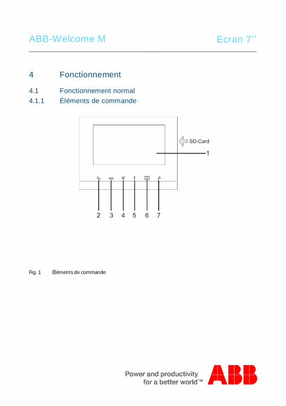
ABB-Welcome M Ecran 7’’
Pos: 18 /Di nA4 - A nleitu ngen Onlin e/Ueb ersc hrift en/1 ./Bedie nun g @ 18\m od_ 130 261 392 416 5_15 .docx @ 1 033 65 @ 1 @ 1
4 FonctionnementPos: 19 /Di nA4 - A nleitu ngen Onlin e/Ueb ersc hrift en/2 ./Nor male r Bet rieb @ 18 \mo d_1 302 768 8209 65_ 15. docx @ 10 3540 @ 2 @ 1
4.1 Fonctionnement normalPos: 20 /Di nA4 - A nleitu ngen Onlin e/Ueb ersc hrift en/3 ./Bedie nele men te @ 20\ mod _13 232 6022 055 9_1 5.do cx @ 1 116 47 @ 3 @ 1
4.1.1 Éléments de commandePos: 21 /Di nA4 - A nleitu ngen Onlin e/In halt/KNX/Do orEnt ry/83 220 -AP-xxx/Be dienel eme nte - 8 322 0-AP-xxx @ 18\ mo d_1 3032 128 536 05_ 15.d ocx @ 103 673 @ @ 1
Fig. 1 Éléments de commande
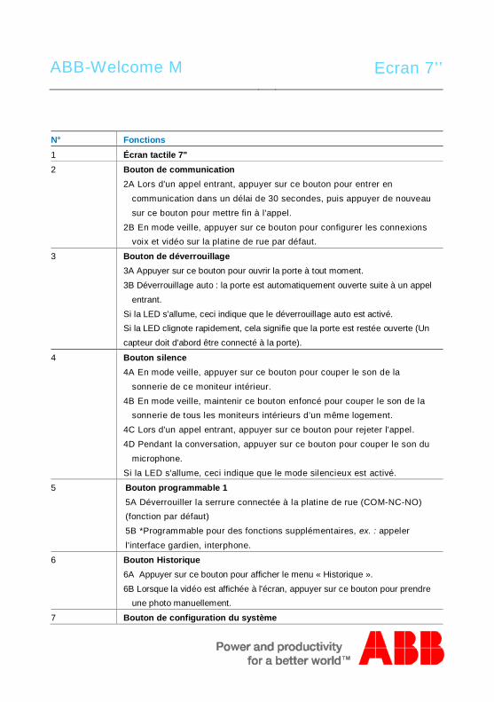
ABB-Welcome M Ecran 7’’
N° Fonctions1 Écran tactile 7"2 Bouton de communication
2A Lors d'un appel entrant, appuyer sur ce bouton pour entrer encommunication dans un délai de 30 secondes, puis appuyer de nouveausur ce bouton pour mettre fin à l'appel.
2B En mode veille, appuyer sur ce bouton pour configurer les connexionsvoix et vidéo sur la platine de rue par défaut.
3 Bouton de déverrouillage3A Appuyer sur ce bouton pour ouvrir la porte à tout moment.3B Déverrouillage auto : la porte est automatiquement ouverte suite à un appel
entrant.Si la LED s'allume, ceci indique que le déverrouillage auto est activé.Si la LED clignote rapidement, cela signifie que la porte est restée ouverte (Uncapteur doit d'abord être connecté à la porte).
4 Bouton silence4A En mode veille, appuyer sur ce bouton pour couper le son de la
sonnerie de ce moniteur intérieur.4B En mode veille, maintenir ce bouton enfoncé pour couper le son de la
sonnerie de tous les moniteurs intérieurs d’un même logement.4C Lors d'un appel entrant, appuyer sur ce bouton pour rejeter l'appel.4D Pendant la conversation, appuyer sur ce bouton pour couper le son du
microphone.Si la LED s'allume, ceci indique que le mode silencieux est activé.
5 Bouton programmable 15A Déverrouiller la serrure connectée à la platine de rue (COM-NC-NO)(fonction par défaut)5B *Programmable pour des fonctions supplémentaires, ex. : appelerl'interface gardien, interphone.
6 Bouton Historique6A Appuyer sur ce bouton pour afficher le menu « Historique ».6B Lorsque la vidéo est affichée à l'écran, appuyer sur ce bouton pour prendre
une photo manuellement.
7 Bouton de configuration du système
ABB-Welcome M Ecran 7’’
Permet d'accéder au menu de configuration du système pour les diversesfonctions de l'appareil.
*Pour l'utilisation de ce bouton, veuillez contacter votre électricien.
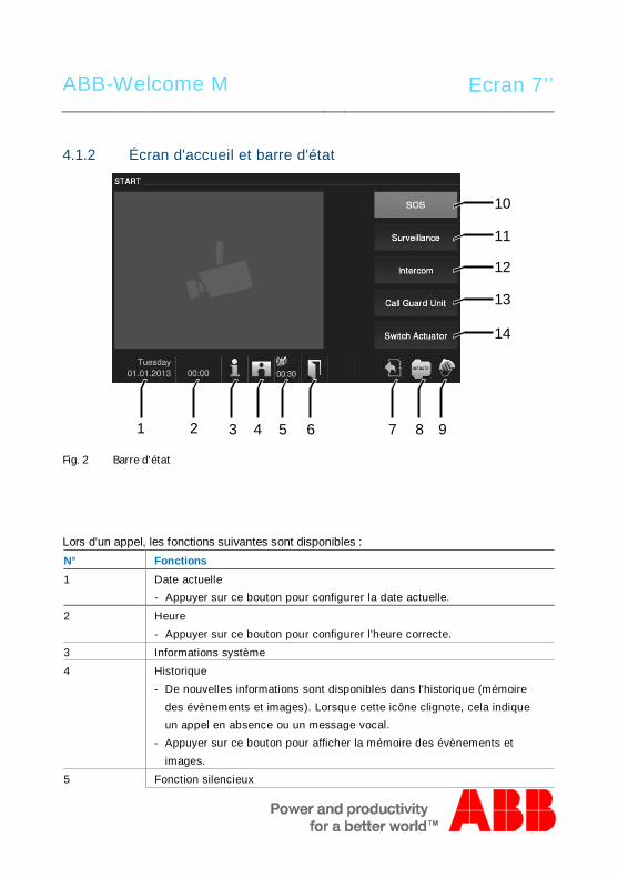
ABB-Welcome M Ecran 7’’
4.1.2 Écran d'accueil et barre d'état
Fig. 2 Barre d'état
Lors d'un appel, les fonctions suivantes sont disponibles :N° Fonctions1 Date actuelle
- Appuyer sur ce bouton pour configurer la date actuelle.
2 Heure- Appuyer sur ce bouton pour configurer l'heure correcte.
3 Informations système
4 Historique- De nouvelles informations sont disponibles dans l'historique (mémoire
des évènements et images). Lorsque cette icône clignote, cela indiqueun appel en absence ou un message vocal.
- Appuyer sur ce bouton pour afficher la mémoire des évènements etimages.
5 Fonction silencieux
3 92 4 65 7 8
10
1
11
12
13
14
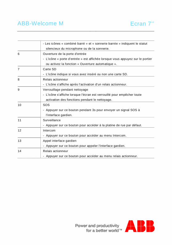
ABB-Welcome M Ecran 7’’
- Les icônes « combiné barré » et « sonnerie barrée » indiquent le statutsilencieux du microphone ou de la sonnerie.
6 Ouverture de la porte d'entrée- L'icône « porte d'entrée » est affichée lorsque vous appuyez sur le portier
ou activez la fonction « Ouverture automatique ».
7 Carte SD- L'icône indique si vous avez inséré ou non une carte SD.
8 Relais actionneur- L'icône s'affiche après l'activation d’un relais actionneur.
9 Verrouillage pendant nettoyage- L'icône s'affiche lorsque l'écran est verrouillé pour empêcher toute
activation des fonctions pendant le nettoyage.
10 SOS- Appuyer sur ce bouton pendant 3s pour envoyer un signal SOS à
l'interface gardien.
11 Surveillance- Appuyer sur ce bouton pour accéder à la platine de rue par défaut.
12 Intercom- Appuyer sur ce bouton pour accéder au menu Intercom.
13 Appel interface gardien- Appuyer sur ce bouton pour appeler l'interface gardien.
14 Relais actionneur- Appuyer sur ce bouton pour accéder au menu relais actionneur.
Pos: 29 /B usch-J aeg er (Neus truk tur )/M odul -Strukt ur/O nline -Doku me ntatio n/Steu er mod ule - Onlin e-Dok ume ntati on ( -- > Für alle Dok ume nte <- -)/ +++ ++ ++ +++ ++ S eiten umb ruch + +++ ++ ++ +++ + @ 9\m od_ 126 8898 668 093 _0. docx @ 521 49 @ @ 1
Pos: 22 /B usch-J aeg er (Neus truk tur )/M odul -Strukt ur/O nline -Doku me ntatio n/Steu er mod ule - Onlin e-Dok ume ntati on ( -- > Für alle Dok ume nte <- -)/ +++ ++ ++ +++ ++ S eiten umb ruch + +++ ++ ++ +++ + @ 9\m od_ 126 8898 668 093 _0. docx @ 521 49 @ @ 1
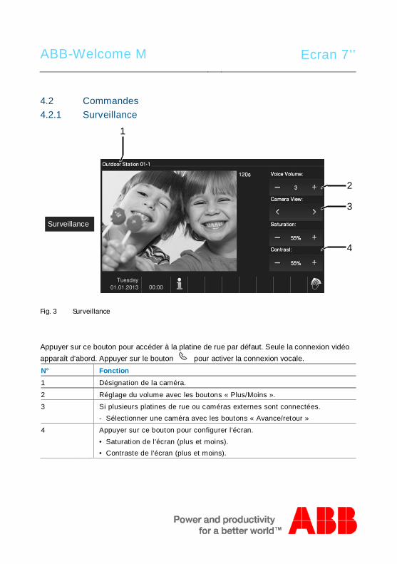
ABB-Welcome M Ecran 7’’
Pos: 26 /Di nA4 - A nleitu ngen Onlin e/Ueb ersc hrift en/2 ./Bedie nakti onen @ 2 0\m od_ 1323 262 294 281 _15. docx @ 11 191 1 @ 2 @ 1
4.2 CommandesPos: 27 /Di nA4 - A nleitu ngen Onlin e/Ueb ersc hrift en/3 ./Spr ech- und Videov erbi ndu ng @ 20\ mod _13 232 6236 870 0_1 5.do cx @ 1119 27 @ 3 @ 1
4.2.1 SurveillancePos: 28 /Di nA4 - A nleitu ngen Onlin e/In halt/KNX/Do orEnt ry/83 220 -AP-xxx/Sp rech - u nd Vide over bind ung - 8 322 0-AP-xxx @ 20\ mo d_1 3232 623 418 52_ 15.d ocx @ 111 919 @ @ 1
Fig. 3 Surveillance
Appuyer sur ce bouton pour accéder à la platine de rue par défaut. Seule la connexion vidéoapparaît d'abord. Appuyer sur le bouton pour activer la connexion vocale.N° Fonction1 Désignation de la caméra.
2 Réglage du volume avec les boutons « Plus/Moins ».
3 Si plusieurs platines de rue ou caméras externes sont connectées.- Sélectionner une caméra avec les boutons « Avance/retour »
4 Appuyer sur ce bouton pour configurer l'écran.• Saturation de l'écran (plus et moins).• Contraste de l'écran (plus et moins).
Pos: 29 /B usch-J aeg er (Neus truk tur )/M odul -Strukt ur/O nline -Doku me ntatio n/Steu er mod ule - Onlin e-Dok ume ntati on ( -- > Für alle Dok ume nte <- -)/ +++ ++ ++ +++ ++ S eiten umb ruch + +++ ++ ++ +++ + @ 9\m od_ 126 8898 668 093 _0. docx @ 521 49 @ @ 1
2
3
4
1
Surveillance
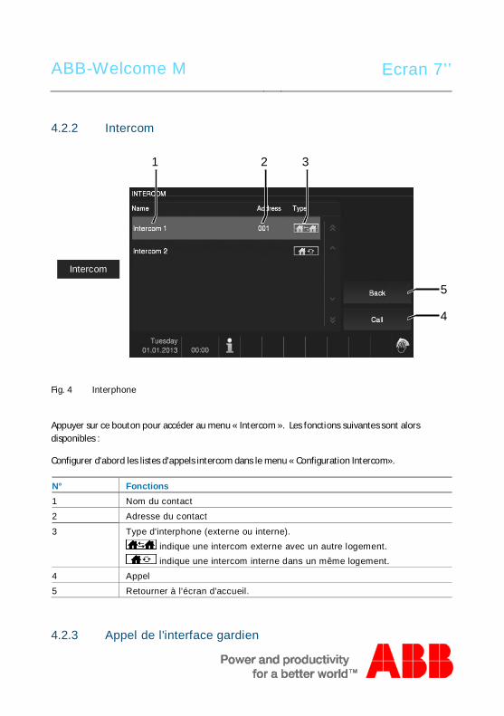
ABB-Welcome M Ecran 7’’
Pos: 30 /Di nA4 - A nleitu ngen Onlin e/Ueb ersc hrift en/3 ./Tuer oeff nen @ 2 0\mo d_1 323 263 277 453 _15. docx @ 11 193 5 @ 3 @ 1
4.2.2 IntercomPos: 31 /Di nA4 - A nleitu ngen Onlin e/In halt/KNX/Do orEnt ry/83 220 -AP-xxx/ Tue r o effne n - 832 20-AP-x xx @ 20\m od_ 132 326 795 847 9_15 .docx @ 1 121 09 @ @ 1
Fig. 4 Interphone
Appuyer sur ce bouton pour accéder au menu « Intercom ». Les fonctions suivantes sont alorsdisponibles :
Configurer d'abord les listes d'appels intercom dans le menu « Configuration Intercom».
N° Fonctions1 Nom du contact
2 Adresse du contact
3 Type d'interphone (externe ou interne). indique une intercom externe avec un autre logement. indique une intercom interne dans un même logement.
4 Appel
5 Retourner à l'écran d'accueil.
4.2.3 Appel de l'interface gardien
4
1
Intercom
5
2 3
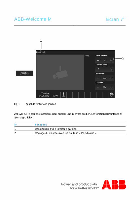
ABB-Welcome M Ecran 7’’
Pos: 31 /Di nA4 - A nleitu ngen Onlin e/In halt/KNX/Do orEnt ry/83 220 -AP-xxx/ Tue r o effne n - 832 20-AP-x xx @ 20\m od_ 132 326 795 847 9_15 .docx @ 1 121 09 @ @ 1
Fig. 5 Appel de l'interface gardien
Appuyer sur le bouton « Gardien » pour appeler une interface gardien. Les fonctions suivantes sontalors disponibles :
N° Fonctions1 Désignation d'une interface gardien2 Réglage du volume avec les boutons « Plus/Moins ».
Appel del'interface
2
1
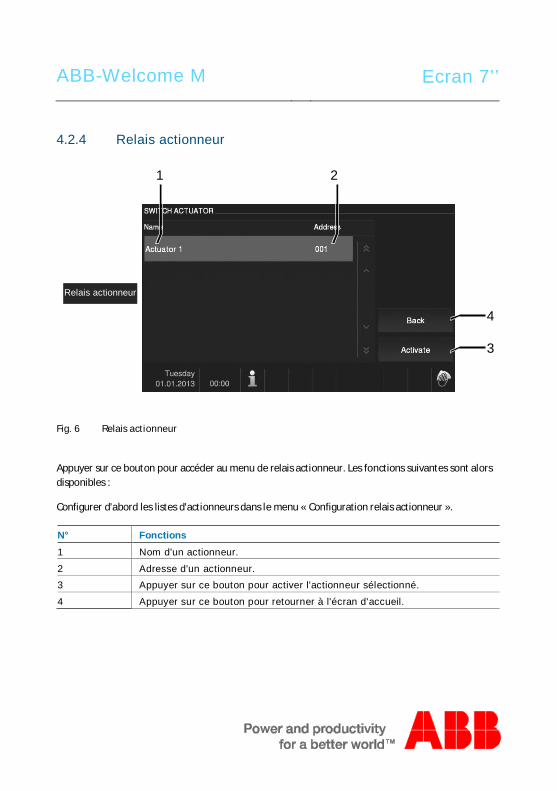
ABB-Welcome M Ecran 7’’
4.2.4 Relais actionneurPos: 31 /Di nA4 - A nleitu ngen Onlin e/In halt/KNX/Do orEnt ry/83 220 -AP-xxx/ Tue r o effne n - 832 20-AP-x xx @ 20\m od_ 132 326 795 847 9_15 .docx @ 1 121 09 @ @ 1
Fig. 6 Relais actionneur
Appuyer sur ce bouton pour accéder au menu de relais actionneur. Les fonctions suivantes sont alorsdisponibles :
Configurer d'abord les listes d'actionneurs dans le menu « Configuration relais actionneur ».
N° Fonctions1 Nom d'un actionneur.
2 Adresse d'un actionneur.3 Appuyer sur ce bouton pour activer l'actionneur sélectionné.
4 Appuyer sur ce bouton pour retourner à l'écran d'accueil.
Relais actionneur
4
1 2
3
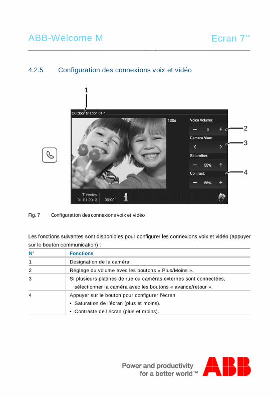
ABB-Welcome M Ecran 7’’
4.2.5 Configuration des connexions voix et vidéoPos: 31 /Di nA4 - A nleitu ngen Onlin e/In halt/KNX/Do orEnt ry/83 220 -AP-xxx/ Tue r o effne n - 832 20-AP-x xx @ 20\m od_ 132 326 795 847 9_15 .docx @ 1 121 09 @ @ 1
Fig. 7 Configuration des connexions voix et vidéo
Les fonctions suivantes sont disponibles pour configurer les connexions voix et vidéo (appuyersur le bouton communication) :N° Fonctions1 Désignation de la caméra.
2 Réglage du volume avec les boutons « Plus/Moins ».
3 Si plusieurs platines de rue ou caméras externes sont connectées,sélectionner la caméra avec les boutons « avance/retour ».
4 Appuyer sur le bouton pour configurer l'écran.• Saturation de l'écran (plus et moins).• Contraste de l'écran (plus et moins).
Pos: 29 /B usch-J aeg er (Neus truk tur )/M odul -Strukt ur/O nline -Doku me ntatio n/Steu er mod ule - Onlin e-Dok ume ntati on ( -- > Für alle Dok ume nte <- -)/ +++ ++ ++ +++ ++ S eiten umb ruch + +++ ++ ++ +++ + @ 9\m od_ 126 8898 668 093 _0. docx @ 521 49 @ @ 1
2
3
4
1
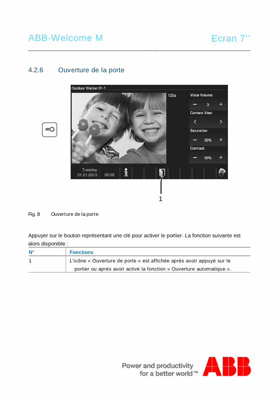
ABB-Welcome M Ecran 7’’
4.2.6 Ouverture de la portePos: 31 /Di nA4 - A nleitu ngen Onlin e/In halt/KNX/Do orEnt ry/83 220 -AP-xxx/ Tue r o effne n - 832 20-AP-x xx @ 20\m od_ 132 326 795 847 9_15 .docx @ 1 121 09 @ @ 1
Fig. 8 Ouverture de la porte
Appuyer sur le bouton représentant une clé pour activer le portier. La fonction suivante estalors disponible :N° Fonctions1 L'icône « Ouverture de porte » est affichée après avoir appuyé sur le
portier ou après avoir activé la fonction « Ouverture automatique ».
1
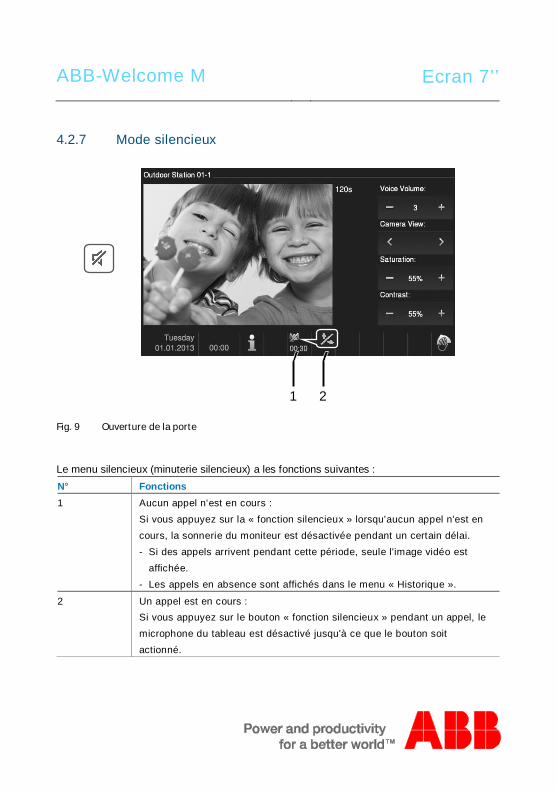
ABB-Welcome M Ecran 7’’
4.2.7 Mode silencieuxPos: 31 /Di nA4 - A nleitu ngen Onlin e/In halt/KNX/Do orEnt ry/83 220 -AP-xxx/ Tue r o effne n - 832 20-AP-x xx @ 20\m od_ 132 326 795 847 9_15 .docx @ 1 121 09 @ @ 1
Fig. 9 Ouverture de la porte
Le menu silencieux (minuterie silencieux) a les fonctions suivantes :N° Fonctions1 Aucun appel n'est en cours :
Si vous appuyez sur la « fonction silencieux » lorsqu'aucun appel n'est encours, la sonnerie du moniteur est désactivée pendant un certain délai.- Si des appels arrivent pendant cette période, seule l'image vidéo est
affichée.- Les appels en absence sont affichés dans le menu « Historique ».
2 Un appel est en cours :Si vous appuyez sur le bouton « fonction silencieux » pendant un appel, lemicrophone du tableau est désactivé jusqu'à ce que le bouton soitactionné.
1 2
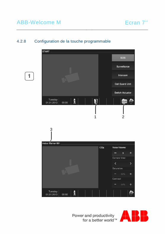
ABB-Welcome M Ecran 7’’
4.2.8 Configuration de la touche programmablePos: 31 /Di nA4 - A nleitu ngen Onlin e/In halt/KNX/Do orEnt ry/83 220 -AP-xxx/ Tue r o effne n - 832 20-AP-x xx @ 20\m od_ 132 326 795 847 9_15 .docx @ 1 121 09 @ @ 1
1 2
3
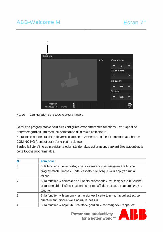
ABB-Welcome M Ecran 7’’
Fig. 10 Configuration de la touche programmable
La touche programmable peut être configurée avec différentes fonctions, ex. : appel del'interface gardien, intercom ou commande d’un relais actionneur.Sa fonction par défaut est le déverrouillage de la 2e serrure, qui est connectée aux bornesCOM-NC-NO (contact sec) d'une platine de rue.Seules la liste d’intercom existante et la liste de relais actionneurs peuvent être assignées àcette touche programmable.
N° Fonctions1 Si la fonction « déverrouillage de la 2e serrure » est assignée à la touche
programmable, l'icône « Porte » est affichée lorsque vous appuyez sur la
touche.
2 Si la fonction « commande du relais actionneur » est assignée à la toucheprogrammable, l'icône « actionneur » est affichée lorsque vous appuyez latouche.
3 Si la fonction « Intercom » est assignée à cette touche, l'appel est activédirectement lorsque vous appuyez dessus.
4 Si la fonction « appel de l'interface gardien » est assignée, l'appel est
4
ABB-Welcome M Ecran 7’’
activé directement lorsque vous appuyez sur la touche.
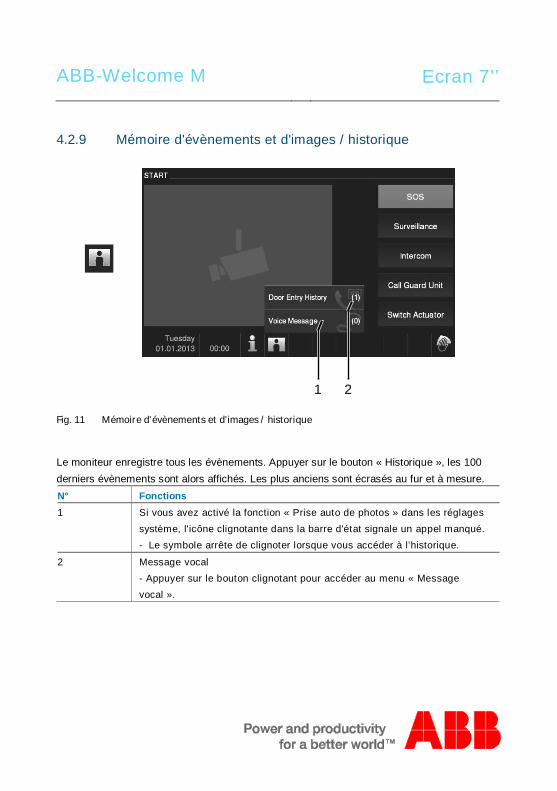
ABB-Welcome M Ecran 7’’
4.2.9 Mémoire d'évènements et d'images / historiquePos: 31 /Di nA4 - A nleitu ngen Onlin e/In halt/KNX/Do orEnt ry/83 220 -AP-xxx/ Tue r o effne n - 832 20-AP-x xx @ 20\m od_ 132 326 795 847 9_15 .docx @ 1 121 09 @ @ 1
Fig. 11 Mémoire d'évènements et d'images / historique
Le moniteur enregistre tous les évènements. Appuyer sur le bouton « Historique », les 100derniers évènements sont alors affichés. Les plus anciens sont écrasés au fur et à mesure.N° Fonctions1 Si vous avez activé la fonction « Prise auto de photos » dans les réglages
système, l'icône clignotante dans la barre d'état signale un appel manqué.- Le symbole arrête de clignoter lorsque vous accéder à l’historique.
2 Message vocal- Appuyer sur le bouton clignotant pour accéder au menu « Messagevocal ».
1 2
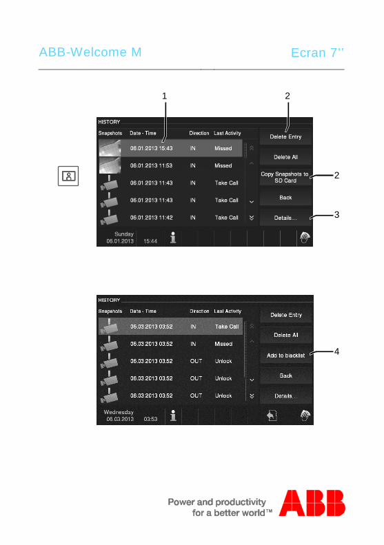
ABB-Welcome M Ecran 7’’
1 2
2
3
4
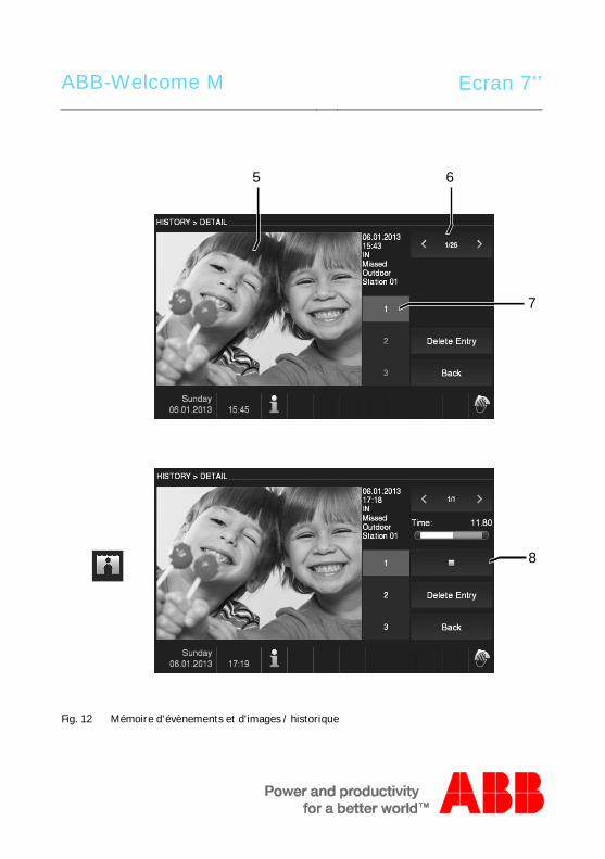
ABB-Welcome M Ecran 7’’
Fig. 12 Mémoire d'évènements et d'images / historique
8
5 6
7
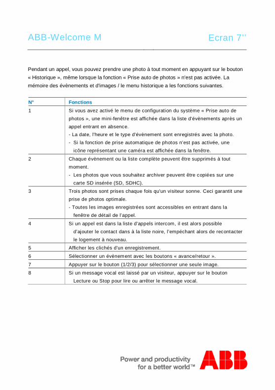
ABB-Welcome M Ecran 7’’
Pendant un appel, vous pouvez prendre une photo à tout moment en appuyant sur le bouton« Historique », même lorsque la fonction « Prise auto de photos » n'est pas activée. Lamémoire des évènements et d'images / le menu historique a les fonctions suivantes.
N° Fonctions1 Si vous avez activé le menu de configuration du système « Prise auto de
photos », une mini-fenêtre est affichée dans la liste d'évènements après unappel entrant en absence.- La date, l'heure et le type d'évènement sont enregistrés avec la photo.- Si la fonction de prise automatique de photos n'est pas activée, une
icône représentant une caméra est affichée dans la fenêtre.
2 Chaque évènement ou la liste complète peuvent être supprimés à toutmoment.- Les photos que vous souhaitez archiver peuvent être copiées sur une
carte SD insérée (SD, SDHC).
3 Trois photos sont prises chaque fois qu'un visiteur sonne. Ceci garantit uneprise de photos optimale.- Toutes les images enregistrées sont accessibles en entrant dans la
fenêtre de détail de l’appel.
4 Si un appel est dans la liste d'appels intercom, il est alors possibled’ajouter le contact dans à la liste noire, l’empéchant alors de recontacterle logement à nouveau.
5 Afficher les clichés d'un enregistrement.
6 Sélectionner un évènement avec les boutons « avance/retour ».
7 Appuyer sur le bouton (1/2/3) pour sélectionner une seule image.
8 Si un message vocal est laissé par un visiteur, appuyer sur le boutonLecture ou Stop pour lire ou arrêter le message vocal.
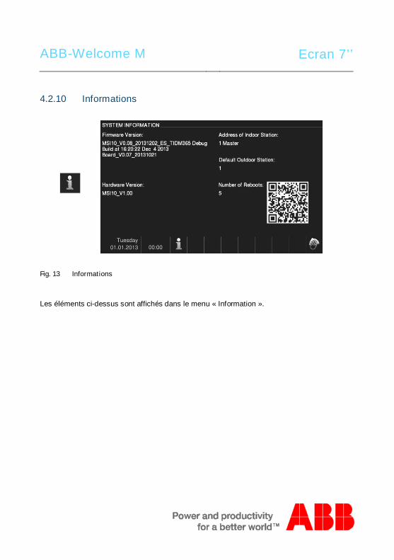
ABB-Welcome M Ecran 7’’
4.2.10 InformationsPos: 31 /Di nA4 - A nleitu ngen Onlin e/In halt/KNX/Do orEnt ry/83 220 -AP-xxx/ Tue r o effne n - 832 20-AP-x xx @ 20\m od_ 132 326 795 847 9_15 .docx @ 1 121 09 @ @ 1
Fig. 13 Informations
Les éléments ci-dessus sont affichés dans le menu « Information ».
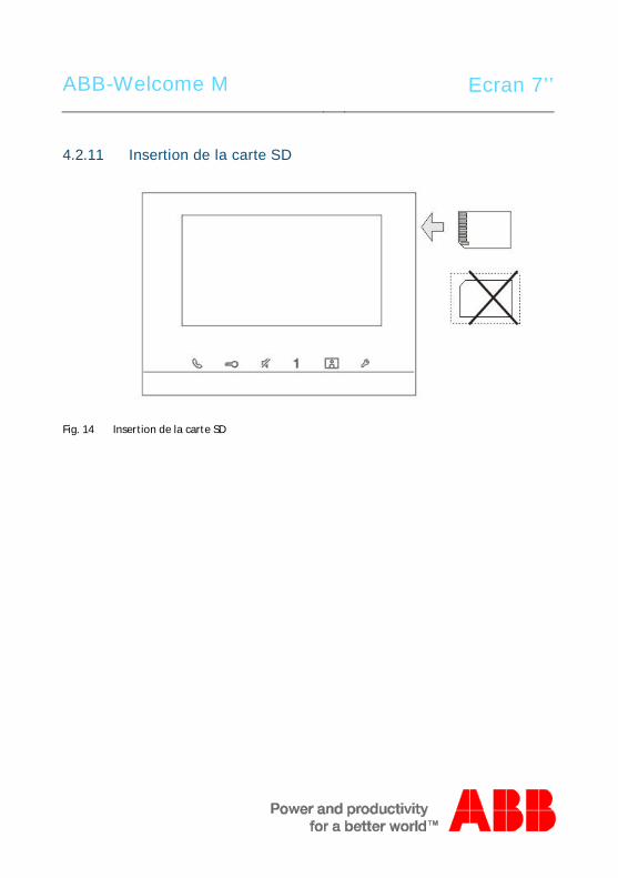
ABB-Welcome M Ecran 7’’
4.2.11 Insertion de la carte SDPos: 31 /Di nA4 - A nleitu ngen Onlin e/In halt/KNX/Do orEnt ry/83 220 -AP-xxx/ Tue r o effne n - 832 20-AP-x xx @ 20\m od_ 132 326 795 847 9_15 .docx @ 1 121 09 @ @ 1
Fig. 14 Insertion de la carte SD

ABB-Welcome M Ecran 7’’
4.2.12 ParamètresPos: 31 /Di nA4 - A nleitu ngen Onlin e/In halt/KNX/Do orEnt ry/83 220 -AP-xxx/ Tue r o effne n - 832 20-AP-x xx @ 20\m od_ 132 326 795 847 9_15 .docx @ 1 121 09 @ @ 1
4.2.12.1 Présentation
Fig. 15 Présentation
Appuyer sur le bouton « Paramètres » pour rendre les champs suivants accessibles :N° Fonctions1 Gestion intercom
- Permet de configurer les listes des intercom entre différents logementet/ou au sein d’un même logement.
2 Relais actionneur- Permet de configurer la liste d'actionneurs dans le menu.
3 Touche programmable- Permet de configurer les fonctions de la touche programmable.
4 Gestion des absences- Réglage du transfert d'appels : Permet de configurer la destination (ex. :
autres moniteurs intérieurs ou interfaces gardien) pour transférer l'appeld'un visiteur lorsque vous n'êtes pas à votre domicile.
- Message d'absence : Si vous n'êtes pas à votre domicile, vous pouvezenregistrer et laisser un message avant de quitter votre domicile pourinformer les éventuels visiteurs ; et vice-versa.
5 Message vocal
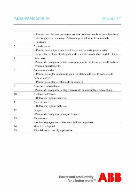
ABB-Welcome M Ecran 7’’
- Permet de créer des messages vocaux pour les membres de la famille oud'enregistrer un message d'absence pour informer les éventuelsvisiteurs.
6 Code de porte- Permet de configurer le code d'ouverture de porte personnalisé,
disponible seulement si la platine de rue est équipée d’un module clavier.
7 Liste noire- Permet de configurer la liste noire pour empêcher les appels indésirablesd'autres appartements.
8 Paramètres audio- Permet de régler la sonnerie pour les platines de rue, la sonnette deporte et autres ;- Permet de régler le volume de la sonnerie.
9 Ouverture automatique- Permet de configurer la plage horaire de déverrouillage automatique.
10 Réglage de l’écran- Différents réglages d'écran.
11 Date et heure- Différents réglages d'heure.
12 Langue- Permet de configurer la langue locale
13 Paramètres- Autres réglages, ex. : prise automatique de photos
14 Mise à jour logiciel
15 Réinitialisation des réglages usine
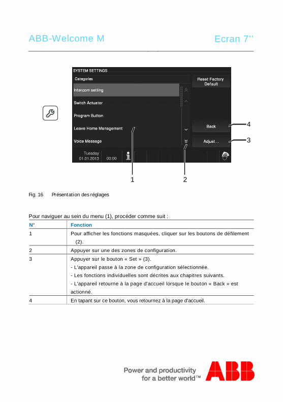
ABB-Welcome M Ecran 7’’
Fig. 16 Présentation des réglages
Pour naviguer au sein du menu (1), procéder comme suit :N° Fonction1 Pour afficher les fonctions masquées, cliquer sur les boutons de défilement
(2).
2 Appuyer sur une des zones de configuration.
3 Appuyer sur le bouton « Set » (3).- L'appareil passe à la zone de configuration sélectionnée.- Les fonctions individuelles sont décrites aux chapitres suivants.- L'appareil retourne à la page d'accueil lorsque le bouton « Back » estactionné.
4 En tapant sur ce bouton, vous retournez à la page d'accueil.
4
1 2
3
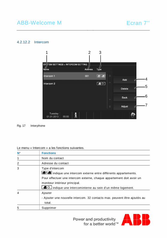
ABB-Welcome M Ecran 7’’
4.2.12.2 Intercom
Fig. 17 Interphone
Le menu « Intercom » a les fonctions suivantes.N° Fonctions1 Nom du contact
2 Adresse du contact
3 Type d'intercom indique une intercom externe entre différents appartements.
Pour effectuer une intercom externe, chaque appartement doit avoir unmoniteur intérieur principal.
indique une intercominterne au sein d’un même logement.
4 Ajouter- Ajouter une nouvelle intercom. 32 contacts max. peuvent être ajoutés au
total.
5 Supprimer
4
5
1 32
6
7

ABB-Welcome M Ecran 7’’
- Cliquer sur ce bouton pour supprimer un contact. Valider la supression.
6 Retour- Cliquer sur ce bouton pour retourner au menu de configuration du
système.
7 Modifier- Cliquer sur ce bouton pour modifier les données d’un contact éxistant.
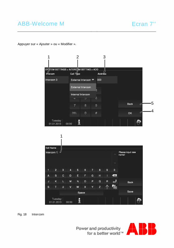
ABB-Welcome M Ecran 7’’
Appuyer sur « Ajouter » ou « Modifier ».
Fig. 18 Intercom
5
4
1 32
1
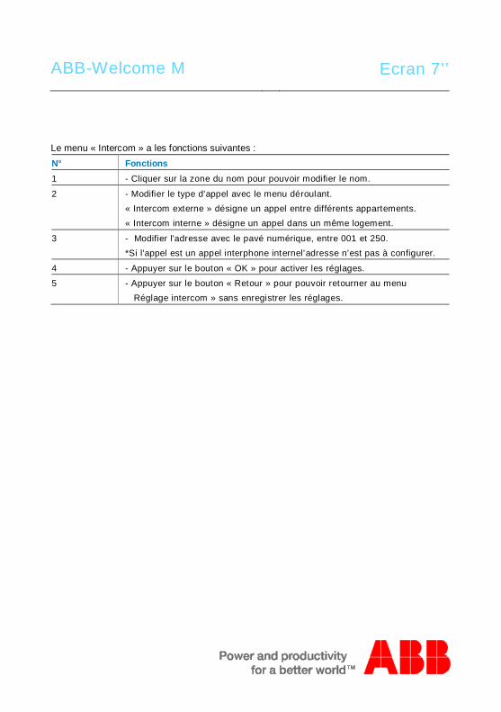
ABB-Welcome M Ecran 7’’
Le menu « Intercom » a les fonctions suivantes :N° Fonctions1 - Cliquer sur la zone du nom pour pouvoir modifier le nom.
2 - Modifier le type d'appel avec le menu déroulant.« Intercom externe » désigne un appel entre différents appartements.« Intercom interne » désigne un appel dans un même logement.
3 - Modifier l'adresse avec le pavé numérique, entre 001 et 250.*Si l'appel est un appel interphone internel’adresse n’est pas à configurer.
4 - Appuyer sur le bouton « OK » pour activer les réglages.
5 - Appuyer sur le bouton « Retour » pour pouvoir retourner au menuRéglage intercom » sans enregistrer les réglages.
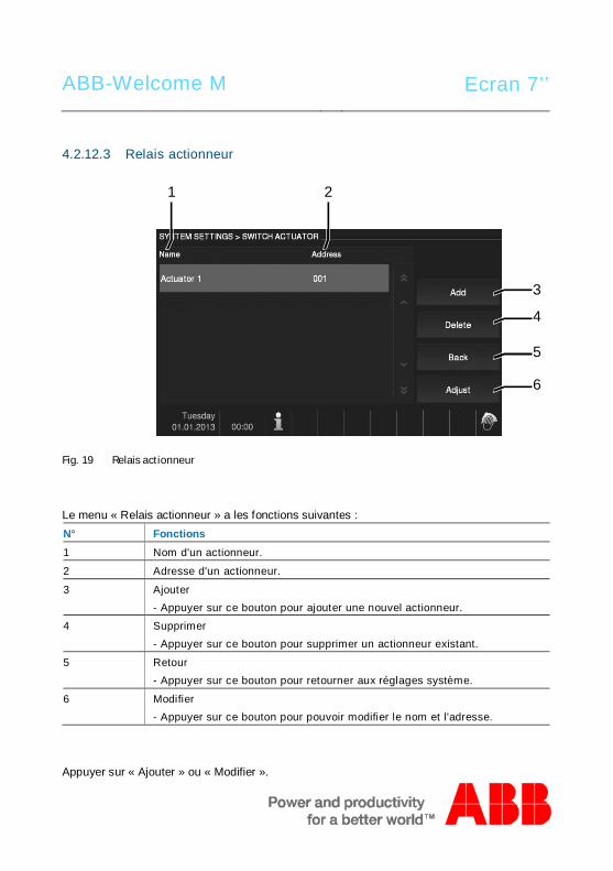
ABB-Welcome M Ecran 7’’
4.2.12.3 Relais actionneur
Fig. 19 Relais actionneur
Le menu « Relais actionneur » a les fonctions suivantes :N° Fonctions1 Nom d'un actionneur.
2 Adresse d'un actionneur.
3 Ajouter- Appuyer sur ce bouton pour ajouter une nouvel actionneur.
4 Supprimer- Appuyer sur ce bouton pour supprimer un actionneur existant.
5 Retour- Appuyer sur ce bouton pour retourner aux réglages système.
6 Modifier- Appuyer sur ce bouton pour pouvoir modifier le nom et l'adresse.
Appuyer sur « Ajouter » ou « Modifier ».
3
4
1 2
5
6
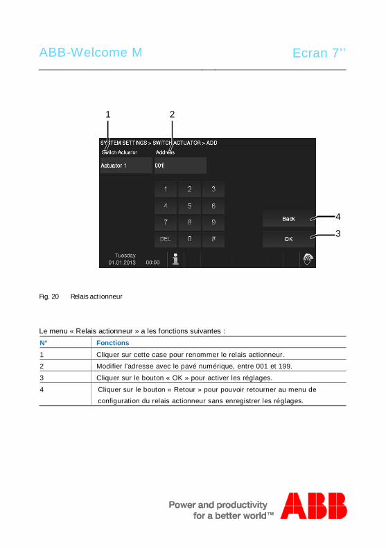
ABB-Welcome M Ecran 7’’
Fig. 20 Relais actionneur
Le menu « Relais actionneur » a les fonctions suivantes :N° Fonctions1 Cliquer sur cette case pour renommer le relais actionneur.
2 Modifier l'adresse avec le pavé numérique, entre 001 et 199.
3 Cliquer sur le bouton « OK » pour activer les réglages.
4 Cliquer sur le bouton « Retour » pour pouvoir retourner au menu deconfiguration du relais actionneur sans enregistrer les réglages.
4
3
1 2
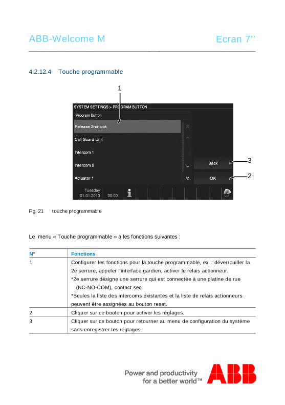
ABB-Welcome M Ecran 7’’
4.2.12.4 Touche programmable
Fig. 21 touche programmable
Le menu « Touche programmable » a les fonctions suivantes :
N° Fonctions1 Configurer les fonctions pour la touche programmable, ex. : déverrouiller la
2e serrure, appeler l'interface gardien, activer le relais actionneur.*2e serrure désigne une serrure qui est connectée à une platine de rue
(NC-NO-COM), contact sec.*Seules la liste des intercoms éxistantes et la liste de relais actionneurspeuvent être assignées au bouton reset.
2 Cliquer sur ce bouton pour activer les réglages.
3 Cliquer sur ce bouton pour retourner au menu de configuration du systèmesans enregistrer les réglages.
3
2
1
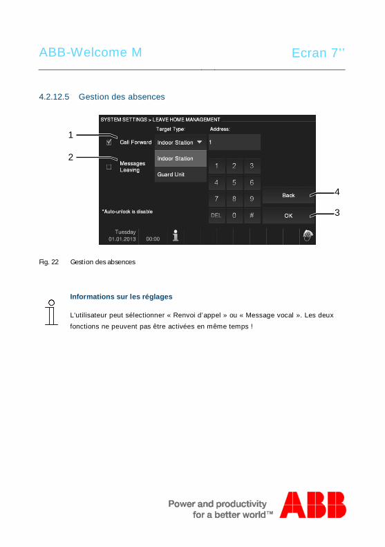
ABB-Welcome M Ecran 7’’
4.2.12.5 Gestion des absences
Fig. 22 Gestion des absences
Informations sur les réglages
L'utilisateur peut sélectionner « Renvoi d’appel » ou « Message vocal ». Les deuxfonctions ne peuvent pas être activées en même temps !
4
3
1
2
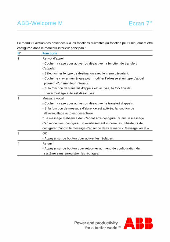
ABB-Welcome M Ecran 7’’
Le menu « Gestion des absences » a les fonctions suivantes (la fonction peut uniquement êtreconfigurée dans le moniteur intérieur principal) :N° Fonctions1 Renvoi d’appel
- Cocher la case pour activer ou désactiver la fonction de transfertd'appels.- Sélectionner le type de destination avec le menu déroulant.- Cocher le clavier numérique pour modifier l'adresse si un type d'appelprovient d'un moniteur intérieur.
- Si la fonction de transfert d'appels est activée, la fonction dedéverrouillage auto est désactivée.
2 Message vocal- Cocher la case pour activer ou désactiver le transfert d'appels.- Si la fonction de message d'absence est activée, la fonction dedéverrouillage auto est désactivée.
* Le message d'absence doit d'abord être configuré. Si aucun messaged'absence n'est configuré, un avertissement informe les utilisateurs deconfigurer d'abord le message d'absence dans le menu « Message vocal ».
3 OK- Appuyer sur ce bouton pour activer les réglages.
4 Retour- Appuyer sur ce bouton pour retourner au menu de configuration dusystème sans enregistrer les réglages.
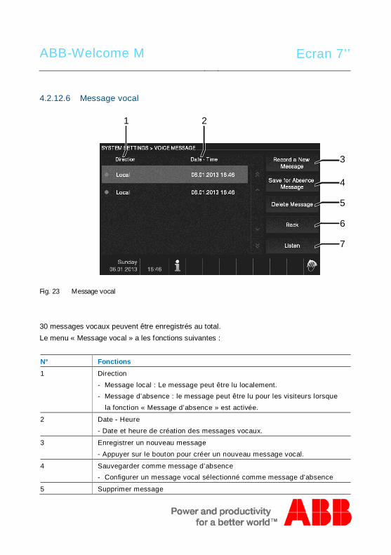
ABB-Welcome M Ecran 7’’
4.2.12.6 Message vocal
Fig. 23 Message vocal
30 messages vocaux peuvent être enregistrés au total.Le menu « Message vocal » a les fonctions suivantes :
N° Fonctions1 Direction
- Message local : Le message peut être lu localement.- Message d’absence : le message peut être lu pour les visiteurs lorsque
la fonction « Message d’absence » est activée.
2 Date - Heure- Date et heure de création des messages vocaux.
3 Enregistrer un nouveau message- Appuyer sur le bouton pour créer un nouveau message vocal.
4 Sauvegarder comme message d’absence- Configurer un message vocal sélectionné comme message d'absence
5 Supprimer message
6
7
1 2
3
4
5
ABB-Welcome M Ecran 7’’
- Cliquer sur ce bouton pour supprimer un message vocal existant. Puis,valider la boîte de dialogue affichée.
6 Retour- Appuyer sur le bouton pour retourner au menu de configuration dusystème.
7 Ecouter- Appuyer sur le bouton pour lire le message vocal.
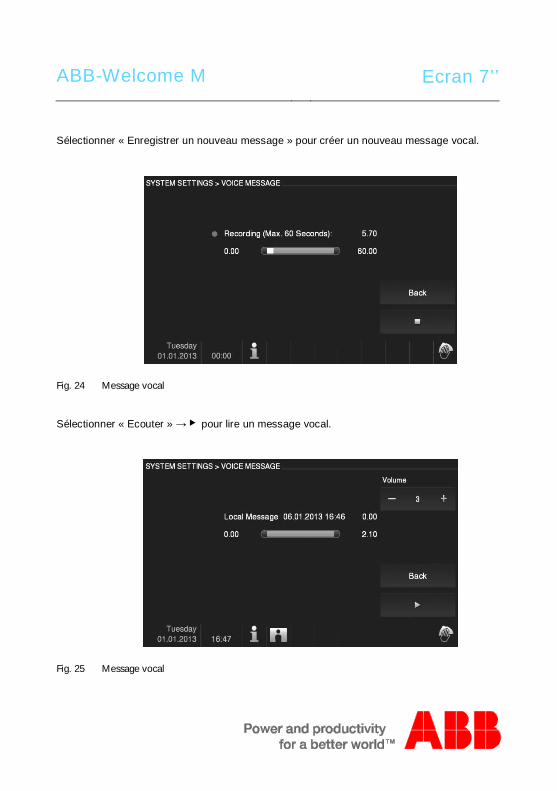
ABB-Welcome M Ecran 7’’
Sélectionner « Enregistrer un nouveau message » pour créer un nouveau message vocal.
Fig. 24 Message vocal
Sélectionner « Ecouter » → ▶ pour lire un message vocal.
Fig. 25 Message vocal

ABB-Welcome M Ecran 7’’
4.2.12.7 Configuration du code d'ouverture de porte
Fig. 26 Configuration du code d'ouverture de porte
Le menu « Configuration du code de porte » a les fonctions suivantes (la fonction peutuniquement être configurée dans le moniteur intérieur principal) :N° Fonctions1 Cocher la case pour activer ou désactiver la fonction de code.
2 Configurer le mot de passe au format 6-8 chiffres.
3 OK- Cliquer sur ce bouton pour activer les réglages.
4 Reour- Appuyer sur ce bouton pour retourner au menu de configuration dusystème.
*Uniquement disponible avec un module clavier sur la platine de rue.
4
3
21
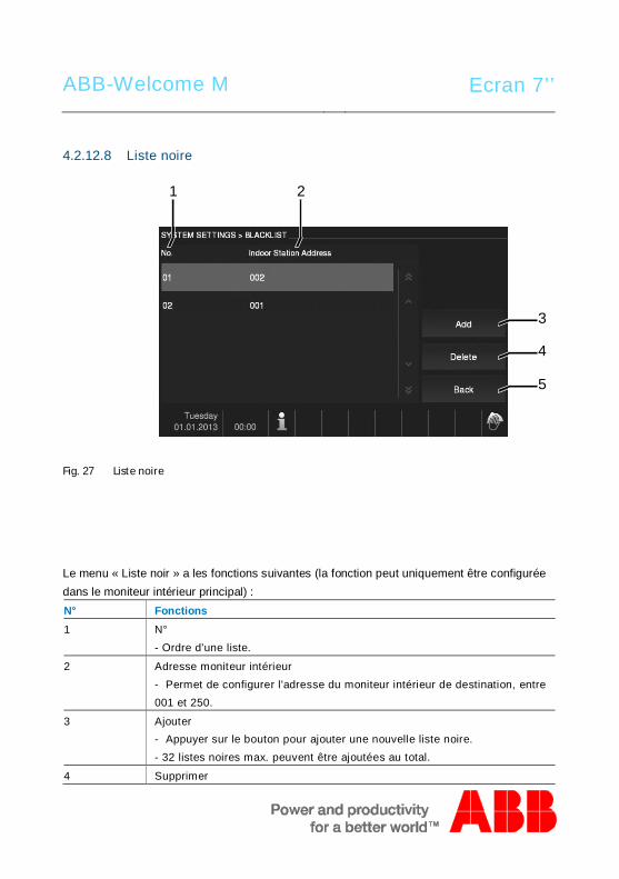
ABB-Welcome M Ecran 7’’
4.2.12.8 Liste noire
Fig. 27 Liste noire
Le menu « Liste noir » a les fonctions suivantes (la fonction peut uniquement être configuréedans le moniteur intérieur principal) :N° Fonctions1 N°
- Ordre d'une liste.
2 Adresse moniteur intérieur- Permet de configurer l'adresse du moniteur intérieur de destination, entre001 et 250.
3 Ajouter- Appuyer sur le bouton pour ajouter une nouvelle liste noire.- 32 listes noires max. peuvent être ajoutées au total.
4 Supprimer
4
5
1 2
3
ABB-Welcome M Ecran 7’’
- Appuyer sur le bouton pour supprimer une liste noire existante.
5 Retour- Appuyer sur ce bouton pour retourner au menu de configuration dusystème.
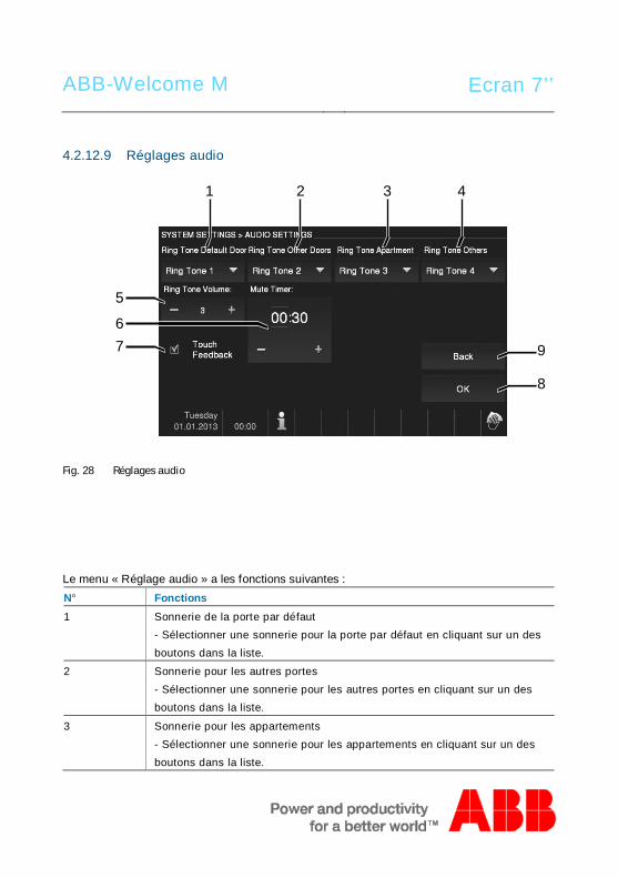
ABB-Welcome M Ecran 7’’
4.2.12.9 Réglages audio
Fig. 28 Réglages audio
Le menu « Réglage audio » a les fonctions suivantes :N° Fonctions1 Sonnerie de la porte par défaut
- Sélectionner une sonnerie pour la porte par défaut en cliquant sur un desboutons dans la liste.
2 Sonnerie pour les autres portes- Sélectionner une sonnerie pour les autres portes en cliquant sur un desboutons dans la liste.
3 Sonnerie pour les appartements- Sélectionner une sonnerie pour les appartements en cliquant sur un desboutons dans la liste.
9
8
1 2
5
3 4
67
ABB-Welcome M Ecran 7’’
4 Sonnerie pour les autres- Sélectionner une sonnerie pour les autres en cliquant sur un des boutons
dans la liste, ex. : un appel d'une interface gardien ou un appelinterphone d'autres appartements.
5 Volume de la sonnerie- Régler le volume de la sonnerie avec les boutons « Plus / Moins ».
6 Minuterie mode silencieux- Utiliser les touches « Plus / Moins » pour régler l'heure de la fonction
silence que vous activez avec le bouton « mute ».- Avant de régler les heures ou minutes, la plage active est encadrée.
7 Touch Feedback- Cocher la case pour activer ou désactiver le retour de son qui est émislorsque l'écran ou le bouton est actionné.
8 OK- Appuyer sur ce bouton pour activer les réglages.
9 Retour- Appuyer sur ce bouton pour retourner au menu de configuration dusystème.
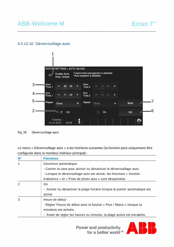
ABB-Welcome M Ecran 7’’
4.2.12.10 Déverrouillage auto
Fig. 29 Déverrouillage auto
Le menu « Déverrouillage auto » a les fonctions suivantes (la fonction peut uniquement êtreconfigurée dans le moniteur intérieur principal) :N° Fonctions1 Ouverture automatique
- Cocher la case pour activer ou désactiver le déverrouillage auto.- Lorsque le déverrouillage auto est activé, les fonctions « Gestiond’absence » et « Prise de photo auto » sont désactivées.
2 On- Activer ou désactiver la plage horaire lorsque le portier automatique estactivé.
3 Heure de début- Régler l'heure de début avec le bouton « Plus / Moins » lorsque laminuterie est activée.- Avant de régler les heures ou minutes, la plage active est encadrée.
7
6
3
1
4
5
2
ABB-Welcome M Ecran 7’’
4 Heure de fin- Régler l'heure de fin avec le bouton « Plus / Moins » lorsque la minuterieest activée.- Avant de régler les heures ou minutes, la plage active est encadrée.
5 Répéter- Permet de configurer la fréquence de répétition avec le menu déroulantlorsque la minuterie est activée.- Si vous sélectionnez « Une fois », la fonction est désactivée après uncertain délai.- Si vous sélectionnez « Tous les jours », la fonction est activée selon unefréquence journalière.- Si vous sélectionnez « En semaine », la fonction est activée uniquementles jours de semaine (du lundi au vendredi).
6 OK- Appuyer sur ce bouton pour activer les réglages.
7 Retour- Appuyer sur ce bouton pour retourner au menu de configuration dusystème sans enregistrer les réglages.
Pos: 32 /B usch-J aeg er (Neus truk tur )/M odul -Strukt ur/O nline -Doku me ntatio n/Steu er mod ule - Onlin e-Dok ume ntati on ( -- > Für alle Dok ume nte <- -)/ +++ ++ ++ +++ ++ S eiten umb ruch + +++ ++ ++ +++ + @ 9\m od_ 126 8898 668 093 _0. docx @ 521 49 @ @ 1
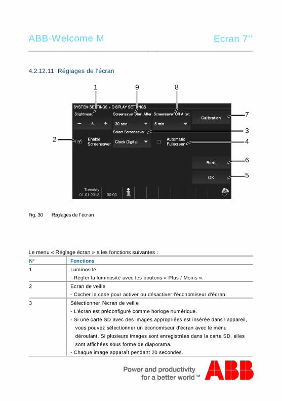
ABB-Welcome M Ecran 7’’
4.2.12.11 Réglages de l'écran
Fig. 30 Réglages de l'écran
Le menu « Réglage écran » a les fonctions suivantes :N° Fonctions1 Luminosité
- Régler la luminosité avec les boutons « Plus / Moins ».
2 Ecran de veille- Cocher la case pour activer ou désactiver l'économiseur d'écran.
3 Sélectionner l’écran de veille- L'écran est préconfiguré comme horloge numérique.- Si une carte SD avec des images appropriées est insérée dans l'appareil,
vous pouvez sélectionner un économiseur d'écran avec le menudéroulant. Si plusieurs images sont enregistrées dans la carte SD, ellessont affichées sous forme de diaporama.
- Chaque image apparaît pendant 20 secondes.
6
5
1 9 8
7
234
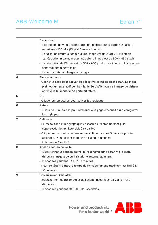
ABB-Welcome M Ecran 7’’
Exigences :- Les images doivent d'abord être enregistrées sur la carte SD dans le
répertoire « DCIM » (Digital Camera Images).- La taille maximum autorisée d'une image est de 2048 x 1960 pixels.- La résolution maximum autorisée d'une image est de 800 x 480 pixels.- La résolution de l'écran est de 800 x 600 pixels. Les images plus grandes
sont réduites à cette taille.- Le format pris en charge est « jpg ».
4 Plein écran auto- Cocher la case pour activer ou désactiver le mode plein écran. Le mode
plein écran reste actif pendant la durée d'affichage de l'image du visiteuraprès que la sonnerie de porte ait retenti.
5 OK- Cliquer sur ce bouton pour activer les réglages.
6 Retour- Cliquer sur ce bouton pour retourner à la page d'accueil sans enregistrer
les réglages.
7 Calibrage- Si les boutons et les graphiques associés à l'écran ne sont plus
superposés, le moniteur doit être calibré.- Cliquer sur le bouton calibration puis cliquer sur les 5 croix de position
affichées. Puis, valider la boîte de dialogue affichée. L'écran a été calibré.
8 Arret de l’écran de veille- Sélectionner la période active de l'économiseur d'écran via le menu
déroulant jusqu'à ce qu'il s'éteigne automatiquement.- Disponible pendant 5 / 15 / 30 minutes.- Pour protéger l'écran, le temps de fonctionnement maximum est limité à
30 minutes.
9 Screen saver Start After- Sélectionner l'heure de début de l'économiseur d'écran via le menu
déroulant.- Disponible pendant 30 / 60 / 120 secondes.
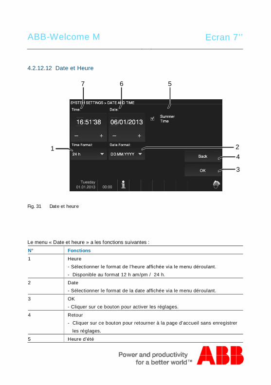
ABB-Welcome M Ecran 7’’
4.2.12.12 Date et Heure
Fig. 31 Date et heure
Le menu « Date et heure » a les fonctions suivantes :N° Fonctions1 Heure
- Sélectionner le format de l'heure affichée via le menu déroulant.- Disponible au format 12 h am/pm / 24 h.
2 Date- Sélectionner le format de la date affichée via le menu déroulant.
3 OK- Cliquer sur ce bouton pour activer les réglages.
4 Retour- Cliquer sur ce bouton pour retourner à la page d'accueil sans enregistrer
les réglages.
5 Heure d’été
4
3
7 6 5
1 2
ABB-Welcome M Ecran 7’’
- Cocher la case pour activer ou désactiver pendant l'heure d'été(basculement automatique).
6 Date- Configurer la date via les boutons « Plus/Moins ».- Avant de régler « Jour », « Mois » ou « Année ». La zone active est
encadrée.
7 Heure- Configurer l'heure avec les boutons « Plus/Moins ».- Avant de régler les « Heure », « Minutes » ou « Secondes », la zone
active est encadrée.
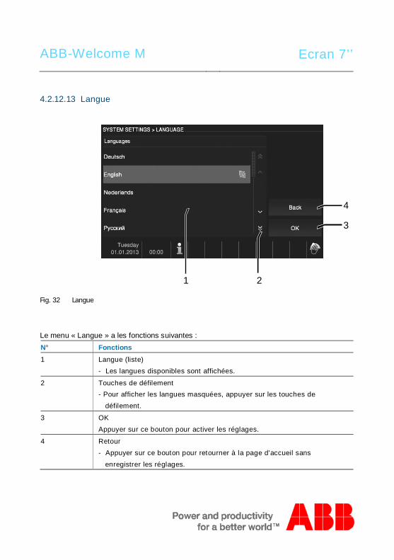
ABB-Welcome M Ecran 7’’
4.2.12.13 Langue
Fig. 32 Langue
Le menu « Langue » a les fonctions suivantes :N° Fonctions1 Langue (liste)
- Les langues disponibles sont affichées.
2 Touches de défilement- Pour afficher les langues masquées, appuyer sur les touches de
défilement.
3 OKAppuyer sur ce bouton pour activer les réglages.
4 Retour- Appuyer sur ce bouton pour retourner à la page d'accueil sans
enregistrer les réglages.
4
3
1 2
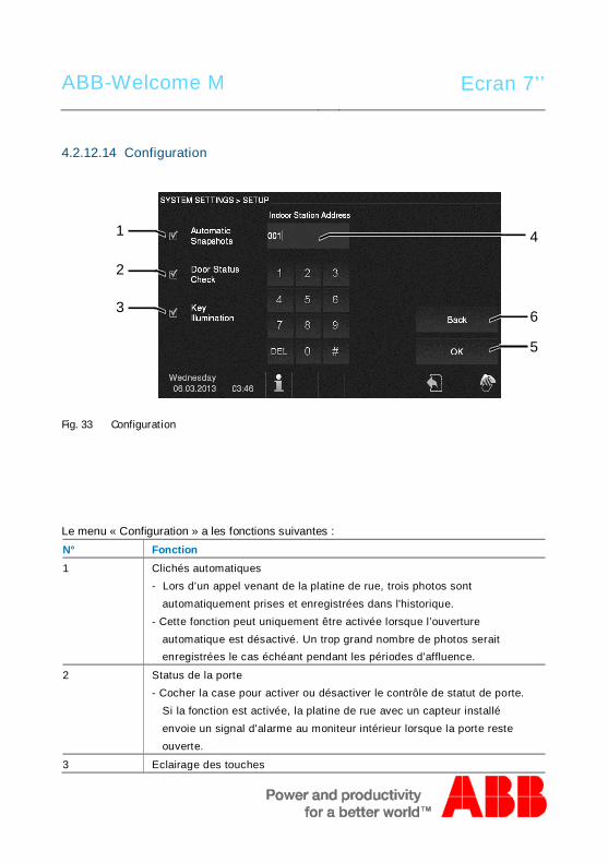
ABB-Welcome M Ecran 7’’
4.2.12.14 Configuration
Fig. 33 Configuration
Le menu « Configuration » a les fonctions suivantes :N° Fonction1 Clichés automatiques
- Lors d’un appel venant de la platine de rue, trois photos sontautomatiquement prises et enregistrées dans l'historique.
- Cette fonction peut uniquement être activée lorsque l’ouvertureautomatique est désactivé. Un trop grand nombre de photos seraitenregistrées le cas échéant pendant les périodes d'affluence.
2 Status de la porte- Cocher la case pour activer ou désactiver le contrôle de statut de porte.
Si la fonction est activée, la platine de rue avec un capteur installéenvoie un signal d'alarme au moniteur intérieur lorsque la porte resteouverte.
3 Eclairage des touches
6
5
1
2
3
4
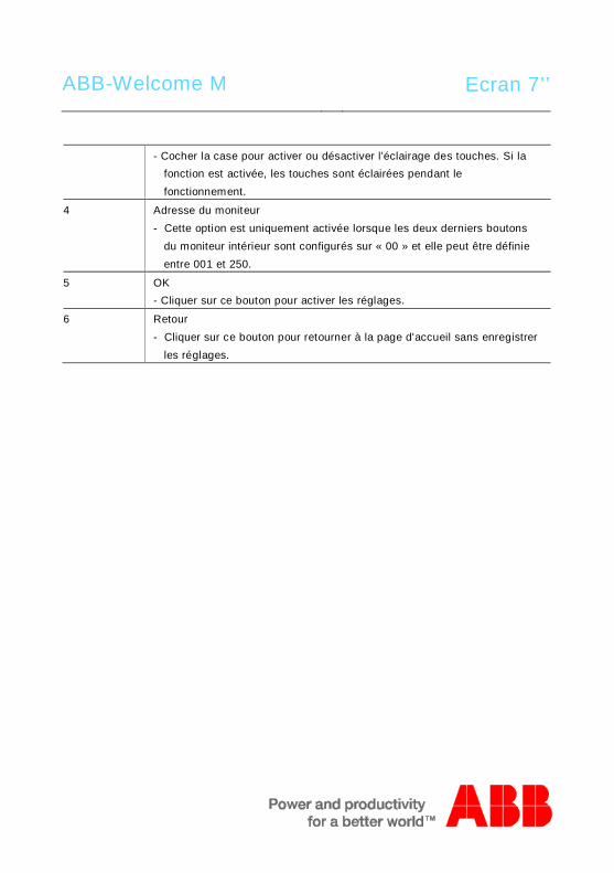
ABB-Welcome M Ecran 7’’
- Cocher la case pour activer ou désactiver l'éclairage des touches. Si lafonction est activée, les touches sont éclairées pendant lefonctionnement.
4 Adresse du moniteur- Cette option est uniquement activée lorsque les deux derniers boutons
du moniteur intérieur sont configurés sur « 00 » et elle peut être définieentre 001 et 250.
5 OK- Cliquer sur ce bouton pour activer les réglages.
6 Retour- Cliquer sur ce bouton pour retourner à la page d'accueil sans enregistrer
les réglages.
ABB-Welcome M Ecran 7’’
4.2.12.15 Mise à jour logicielle
Si le logiciel de votre appareil doit être mis à jour, procéder comme suit :1. Obtenir la nouvelle version du logiciel auprès de l'électricien et la copier sur une carte
SD.2. Insérer la carte SD dans le logement pour cartes du moniteur intérieur.3. Sélectionner « Mise à jour du logiciel ».4. Exécuter le logiciel mis à jour en sélectionnant « Mise à jour ».5. Valider avec « Oui ».Pos: 67 /Di nA4 - A nleitu ngen Onlin e/Ueb ersc hrift en/2 ./Reini gung @ 1 9\m od_ 131 0733 980 533 _15. docx @ 10 785 3 @ 2 @ 1
ABB-Welcome M Ecran 7’’
4.3 NettoyagePos: 68 /Di nA4 - A nleitu ngen Onlin e/In halt/KNX/Do orEnt ry/Reini gun g/Reini gun g Touchsc ree nm onito r @ 19\m od_ 131 073 410 897 8_15 .docx @ 1 078 62 @ @ 1
Attention
Risque d'endommagement de la surface de l'écran.
La surface de l'écran peut être endommagée par des objets durs outranchants !Ne jamais utiliser d'objets pour effectuer des saisies sur l'écran tactile.– Utiliser son doigt ou un stylet en plastique.
La surface de l'écran peut être endommagée par des fluides de nettoyage ouagents abrasifs !– Nettoyer les surfaces à l'aide d'un chiffon doux et d'un produit pour
vitres vendu dans le commerce.– Ne jamais utiliser d'agents de nettoyage abrasifs.
Pos: 69 /B usch-J aeg er (Neus truk tur )/M odul -Strukt ur/O nline -Doku me ntatio n/Steu er mod ule - Onlin e-Dok ume ntati on ( -- > Für alle Dok ume nte <- -)/ +++ ++ ++ +++ ++ S eiten umb ruch + +++ ++ ++ +++ + @ 9\m od_ 126 8898 668 093 _0. docx @ 521 49 @ @ 1
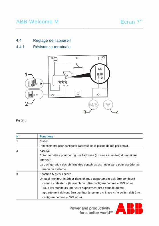
ABB-Welcome M Ecran 7’’
Pos: 70 /Di nA4 - A nleitu ngen Onlin e/Ueb ersc hrift en/2 ./Ge raet eeins tellun gen @ 1 8\mo d_1 302 768 847 744 _15. docx @ 10 354 8 @ 2 @ 1
4.4 Réglage de l'appareilPos: 71 /Di nA4 - A nleitu ngen Onlin e/Ueb ersc hrift en/3 ./Abschl usswide rsta nd @ 19\ mod _13 219 5807 990 6_1 5.do cx @ 1100 83 @ 3 @ 1
Pos: 72 /Di nA4 - A nleitu ngen Onlin e/In halt/KNX/Do orEnt ry/Bedie nun g/Abschl usswide rsta nd s etzen 83 220 -AP-xxx @ 19\ mod _13 1072 339 236 9_1 5.do cx @ 1 078 41 @ @ 1
4.4.1 Résistance terminale
Fig. 34 :Pos: 74 /Di nA4 - A nleitu ngen Onlin e/In halt/KNX/Do orEnt ry/Bedie nun g/M aste r/Slave Sc halte r setz en 832 20-AP-xxx @ 1 9\m od_1 310 723 320 966 _15. docx @ 10 783 3 @ @
N° Fonctions1 Station
Potentiomètre pour configurer l'adresse de la platine de rue par défaut.
2 X10 X1Potenriomètres pour configurer l'adresse (dizaines et unités) du moniteurintérieur.La configuration des chiffres des centaines est nécessaire pour accéder au
menu du système.
3 Fonction Master / SlaveUn seul moniteur intérieur dans chaque appartement doit être configuré
comme « Master » (le switch doit être configuré comme « M/S on »).Tous les moniteurs intérieurs supplémentaires dans le mêmeappartement doivent être configurés comme « Slave » (le switch doit êtreconfiguré comme « M/S off »).
ABB-Welcome M Ecran 7’’
4 Résistance terminaleDans les installations vidéo ou les installations audio/vidéo combinées, le
commutateur doit être configuré comme « RC on » sur le dernier appareilde la ligne.
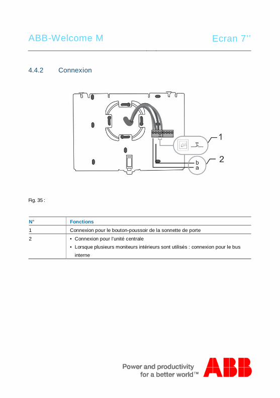
ABB-Welcome M Ecran 7’’
4.4.2 Connexion
Fig. 35 :
N° Fonctions1 Connexion pour le bouton-poussoir de la sonnette de porte
2 • Connexion pour l’unité centrale• Lorsque plusieurs moniteurs intérieurs sont utilisés : connexion pour le bus
interne
Pos: 75 /B usch-J aeg er (Neus truk tur )/M odul -Strukt ur/O nline -Doku me ntatio n/Steu er mod ule - Onlin e-Dok ume ntati on ( -- > Für alle Dok ume nte <- -)/ +++ ++ ++ +++ ++ S eiten umb ruch + +++ ++ ++ +++ + @ 9\m od_ 126 8898 668 093 _0. docx @ 521 49 @ @ 1
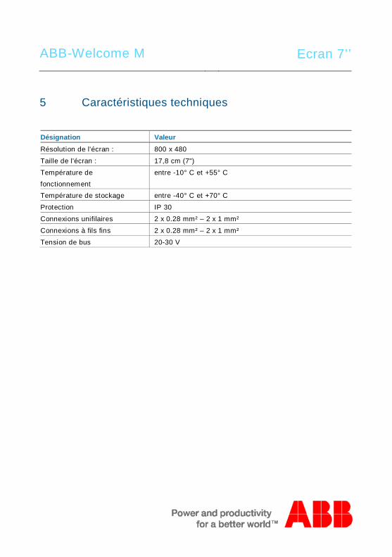
ABB-Welcome M Ecran 7’’
Pos: 76 /Di nA4 - A nleitu ngen Onlin e/Ueb ersc hrift en/1 ./Technisc he D aten @ 18 \mo d_1 302 615 863 001 _15. docx @ 10 341 6 @ 1 @ 1
5 Caractéristiques techniquesPos: 77 /Di nA4 - A nleitu ngen Onlin e/In halt/KNX/Do orEnt ry/83 220 -AP-xxx/ Tech nische Date n - 832 20-AP-x xx @ 1 8\m od_ 130 321 285 4559 _15 .docx @ 1 037 05 @ @ 1
Désignation ValeurRésolution de l'écran : 800 x 480
Taille de l'écran : 17,8 cm (7")
Température defonctionnement
entre -10° C et +55° C
Température de stockage entre -40° C et +70° C
Protection IP 30
Connexions unifilaires 2 x 0.28 mm² – 2 x 1 mm²
Connexions à fils fins 2 x 0.28 mm² – 2 x 1 mm²
Tension de bus 20-30 V
Pos: 78 /B usch-J aeg er (Neus truk tur )/M odul -Strukt ur/O nline -Doku me ntatio n/Steu er mod ule - Onlin e-Dok ume ntati on ( -- > Für alle Dok ume nte <- -)/ +++ ++ ++ +++ ++ S eiten umb ruch + +++ ++ ++ +++ + @ 9\m od_ 126 8898 668 093 _0. docx @ 521 49 @ @ 1
ABB-Welcome M Ecran 7’’
Pos: 79 /B usch-J aeg er (Neus truk tur )/M odul -Strukt ur/O nline -Doku me ntatio n/Übe rsch rifte n ( --> Fü r alle Doku men te < -- )/1. E bene /M - O/ Mont age / Ins tallatio n @ 18\ mod _13 0261 396 611 1_1 5.do cx @ 1 033 73 @ 1 @ 1
6 Montage / InstallationPos: 80 /B usch-J aeg er (Neus truk tur )/M odul -Strukt ur/O nline -Doku me ntatio n/Siche rheit (- -> Fü r alle D oku ment e < --) /War nhinweis e/Siche rheit - Nie ders pan nun gs- und 230 V-Leit ung en @ 18\ mod _13 026 178 214 91_1 5.d ocx @ 103 465 @ @ 1
Avertissement
Tension électrique !
Danger de mort et d'incendie en raison de la présence d'une tensionélectrique de 100-240 V.– Les câbles basse tension et 100-240 V ne doivent pas être installés
ensemble dans une prise encastrée !En cas de court-circuit, il existe un risque de charge 100-240 V sur laligne basse tension.
Pos: 81 /B usch-J aeg er (Neus truk tur )/M odul -Strukt ur/O nline -Doku me ntatio n/Siche rheit (- -> Fü r alle D oku ment e < --) /War nhinweis e/Siche rheit - Fachk enn tnisse @ 18 \mo d_1 302 774 384 017_ 15. docx @ 10 356 4 @ 2 @ 1
ABB-Welcome M Ecran 7’’
6.1 Exigences à l'égard de l'électricien
Avertissement
Tension électrique !
L'installation de l'appareil par un électricien est uniquement possible s'ilpossède les connaissances techniques et compétences nécessaires.• Toute installation incorrecte peut mettre en danger votre vie et celle de
l'utilisateur du système électrique.• Toute installation incorrecte peut entraîner des dommages, p. ex. : en
raison d'un incendie.Les connaissances nécessaires minimum et les exigences relatives à
l'installation sont les suivantes :• Appliquer les « cinq règles de sécurité » (DIN VDE 0105, EN 50110) :
1. Débrancher l'appareil de la source d'alimentation ;2. Empêcher tout rebranchement de l'appareil ;3. S'assurer de l'absence de tension ;4. Raccorder à la terre ;5. Recouvrir ou isoler les pièces voisines sous tension.
• Porter des vêtements de protection appropriés.• Utiliser uniquement des outils et appareils de mesure appropriés.• Vérifier le type de réseau d'alimentation (système TN, système IT,
système TT) pour garantir les conditions d'alimentation électriquessuivantes (connexion à la terre classique, mise à la terre de protection,mesures supplémentaires nécessaires, etc.).
Pos: 82 /Di nA4 - A nleitu ngen Onlin e/In halt/KNX/Do orEnt ry/M onta ge/ Mont age hinweis e - Allg emei n @ 1 9\m od_ 131 056 367 047 8_15 .docx @ 1 077 43 @ 2 @ 1
ABB-Welcome M Ecran 7’’
6.2 Consignes d'installation générales• Terminer toutes les extrémités du système de câblage via un appareil de bus connecté
(p. ex., moniteur intérieur, platine de rue, appareil système).• Ne pas installer le contrôleur système juste à côté du transformateur de sonnerie et
autres alimentations électriques (pour éviter les interférences).• Ne pas installer les câbles du bus système avec des câbles 100-240 V.• Ne pas utiliser des câbles communs pour les câbles de raccordement des portiers et les
câbles du bus système.• Éviter les ponts entre les différents types de câbles.• Utiliser uniquement deux câbles pour le bus système dans un câble à quatre conducteurs
ou plus.• En cas de structure en boucle, ne jamais installer les bus de départ et d'arrivée à
l'intérieur du même câble.• Ne jamais installer les bus interne et externe à l'intérieur du même câble.Pos: 83 /B usch-J aeg er (Neus truk tur )/M odul -Strukt ur/O nline -Doku me ntatio n/Steu er mod ule - Onlin e-Dok ume ntati on ( -- > Für alle Dok ume nte <- -)/ +++ ++ ++ +++ ++ S eiten umb ruch + +++ ++ ++ +++ + @ 9\m od_ 126 8898 668 093 _0. docx @ 521 49 @ @ 1
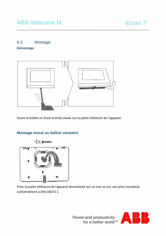
ABB-Welcome M Ecran 7’’
Pos: 84 /B usch-J aeg er (Neus truk tur )/M odul -Strukt ur/O nline -Doku me ntatio n/Übe rsch rifte n ( --> Fü r alle Doku men te < -- )/2. E bene /M - O/ Mont age @ 1 8\m od_1 302 615 960 458 _15. docx @ 10 342 4 @ 2 @ 1
6.3 MontagePos: 85. 1 /DinA4 - Anleit ung en O nline/I nhal t/KNX/DoorE ntry/ 832 20-AP-xxx /Mo nta ge - Mo dule/ Mon tag e - Mon tage dos e -- 83 220 -AP-xxx @ 19\ mod _132 325 040 684 8_1 5.doc x @ 1 110 98 @ @ 1
Démontage
Ouvrir le boîtier en tirant la bride située sur la partie inférieure de l'appareil.
Montage mural ou boîtier encastré
Fixer la partie inférieure de l'appareil directement sur un mur ou sur une prise encastréeconformément à DIN 49073-1.
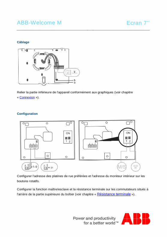
ABB-Welcome M Ecran 7’’
Câblage
Relier la partie inférieure de l'appareil conformément aux graphiques (voir chapitre« Connexion »).
Configuration
Configurer l'adresse des platines de rue préférées et l'adresse du moniteur intérieur sur lesboutons rotatifs.
Configurer la fonction maître/esclave et la résistance terminale sur les commutateurs situés àl'arrière de la partie supérieure du boîtier (voir chapitre « Résistance terminale »).
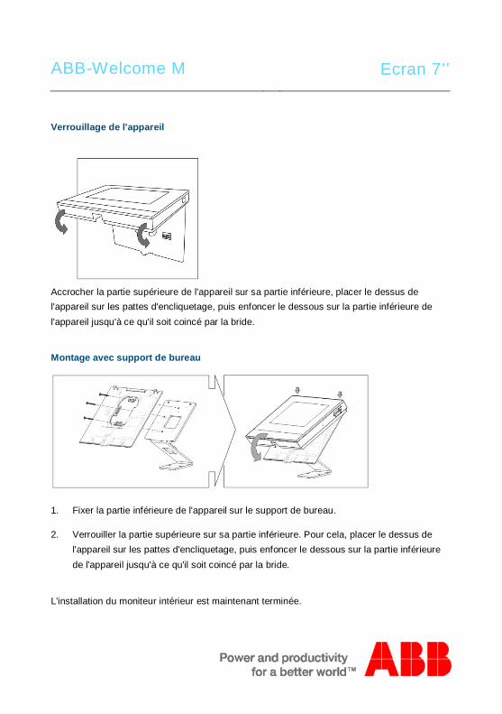
ABB-Welcome M Ecran 7’’
Verrouillage de l'appareil
Accrocher la partie supérieure de l'appareil sur sa partie inférieure, placer le dessus del'appareil sur les pattes d'encliquetage, puis enfoncer le dessous sur la partie inférieure del'appareil jusqu'à ce qu'il soit coincé par la bride.
Montage avec support de bureau
1. Fixer la partie inférieure de l'appareil sur le support de bureau.
2. Verrouiller la partie supérieure sur sa partie inférieure. Pour cela, placer le dessus del'appareil sur les pattes d'encliquetage, puis enfoncer le dessous sur la partie inférieurede l'appareil jusqu'à ce qu'il soit coincé par la bride.
L'installation du moniteur intérieur est maintenant terminée.
Pos: 94 /B usch-J aeg er (Neus truk tur )/M odul -Strukt ur/O nline -Doku me ntatio n/Steu er mod ule - Onlin e-Dok ume ntati on ( -- > Für alle Dok ume nte <- -)/ +++ ++ ++ +++ ++ S eiten umb ruch + +++ ++ ++ +++ + @ 9\m od_ 126 8898 668 093 _0. docx @ 521 49 @ @ 1
ABB-Welcome M Ecran 7’’
Pos: 95 /Di nA4 - A nleitu ngen Onlin e/In halt/KNX/Do orEnt ry/Proj ektier ung -M erkbl att/Pr ojektie rPos: 9 7 /Busc h-Ja ege r (N eust ruktu r)/ Mo dul-Str uktu r/Onli ne-D oku ment ation /Rückseit en (-- > Für alle Dok um ente <- -)/R ückseit e - Bus ch-J aeg er - Allgem ein @ 20\ mod _13 273 200 748 86_1 5.d ocx @ 137 103 @ @ 1
Mentions légales=== E nde der Liste für Tex tma rke Ba ckcove r = ==
Nous nous réservons le droit d'effectuer à tout moment des modifications techniques ou demodifier le contenu de ce document sans préavis.Les spécifications détaillées convenues au moment de la commande s'appliquent à toutes lescommandes. ABB ne peut être tenu responsable des erreurs ou omissions dans ce document. Nous nous réservons tous les droits de propriété sur ce document, ainsi que sur lesinformations et les illustrations qu'il contient. Le document et son contenu, ou extraits de celui-ci, ne doivent pas être reproduits, transmis ou réutilisés par des tiers sans avis écrit préalabled'ABB.
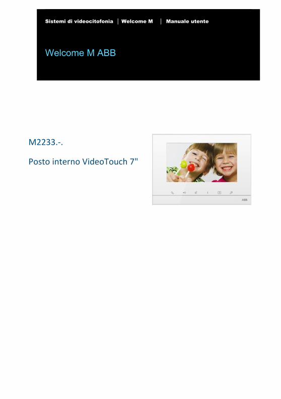
Sistemi di videocitofonia │ Welcome M │ Manuale utente
Welcome M ABB
Pos: 2 /DinA4 - Anleitungen Online/Inhalt/KNX/DoorEntry/83220-AP-xxx/Titelblatt - 83220-AP-xxx - ABB @ 19\mod_1323249806476_15.docx @ 111084 @ @ 1
M2233.‐.
Posto interno VideoTouch 7"
=== Ende der Liste für Textmarke Cover ===
ABB-Welcome
| — 2 —
Pos: 4 /Busch-Jaeger (Neustruktur)/Modul-Struktur/Online-Dokumentation/Inhaltsverzeichnis (--> Für alle Dokumente <--)/Inhaltsverzeichnis @ 19\mod_1320649044386_15.docx @ 109653 @ @ 1
1 Sicurezza .......................................................... 4 2 Uso previsto...................................................... 4 3 Ambiente .......................................................... 4
3.1 Dispositivi ABB ................................ 5 4 Funzionamento ................................................. 6
4.1 Funzionamento standard ................. 6 4.1.1 Comandi ................................................................ 6 4.1.2 Pagina di benvenuto e barra di stato ..................... 8 4.2 Azioni di controllo........................... 10 4.2.1 Controllo .............................................................. 10 4.2.2 Intercom ............................................................... 11 4.2.3 Chiama portineria ................................................ 12 4.2.4 Attuatore .............................................................. 13 4.2.5 Impostazione del collegamento vocale e video ... 14 4.2.6 Apertura porta ...................................................... 15 4.2.7 Funzione Mute ..................................................... 16 4.2.8 Attivazione della funzione di personalizzazione ... 17 4.2.9 Archivio eventi e immagini ................................... 19 4.2.10 Info ....................................................................... 23 4.2.11 Inserimento della scheda SD ............................... 24 4.2.12 Impostazioni ........................................................ 25 4.2.12.1 Panoramica ................................... 25 4.2.12.2 Intercom ......................................... 28 4.2.12.3 Attuatore ........................................ 32 4.2.12.4 Pulsante programmabile ................ 34 4.2.12.5 Gestione Leave Home ................... 35 4.2.12.6 Messaggio vocale .......................... 37 4.2.12.7 Impostazione password porta
aperta ............................................ 40 4.2.12.8 Blacklist ......................................... 41 4.2.12.9 Impostazioni audio ......................... 43 4.2.12.10 Sblocco automatico ....................... 45 4.2.12.11 Impostazioni display ...................... 47 4.2.12.12 Data e ora ...................................... 49 4.2.12.13 Lingua ............................................ 51
ABB-Welcome
| — 3 —
4.2.12.14 Configurazione .............................. 52 4.2.12.15 Aggiornamento Firmware .............. 54 4.3 Pulizia ............................................ 55 4.4 Regolazione del dispositivo ........... 56 4.4.1 Resistenza terminale di chiusura ......................... 56 4.4.2 Collegamento ...................................................... 58
5 Dati tecnici ...................................................... 59 6 Montaggio/Installazione .................................. 60
6.1 Obblighi dell'elettricista .................. 60 6.2 Istruzioni generali di installazione .. 61 6.3 Montaggio ...................................... 62
=== Ende der Liste für Textmarke TOC ===
ABB-Welcome M
| — 4 —
Pos: 6 /Busch-Jaeger (Neustruktur)/Modul-Struktur/Online-Dokumentation/Überschriften (--> Für alle Dokumente <--)/1. Ebene/S - T/Sicherheit @ 18\mod_1302612791790_15.docx @ 103357 @ 1 @ 1
1 Sicurezza Pos: 7 /Busch-Jaeger (Neustruktur)/Modul-Struktur/Online-Dokumentation/Sicherheit (--> Für alle Dokumente <--)/Warnhinweise/Sicherheit - 230 V @ 18\mod_1302606816750_15.docx @ 103308 @ @ 1
Attenzione
Tensione elettrica!
Rischio di morte ed incendio dovuto alla presenza di tensione elettrica 100-
240 V.
– Gli interventi sul sistema di alimentazione 100-240V possono essere
effettuati solo da elettricisti autorizzati.
– Scollegare l'alimentazione di rete prima dell'installazione e/o dello
smontaggio.
Pos: 8 /Busch-Jaeger (Neustruktur)/Modul-Struktur/Online-Dokumentation/Überschriften (--> Für alle Dokumente <--)/1. Ebene/A - F/Bestimmungsgemäßer Gebrauch @ 18\mod_1302763321316_15.docx @ 103483 @ 1 @ 1
2 Uso previsto Pos: 9 /DinA4 - Anleitungen Online/Inhalt/KNX/DoorEntry/83220-AP-xxx/Bestimmungsgemaesser Gebrauch - 83220-AP-xxx-500 @ 20\mod_1324561168699_15.docx @ 112728 @ @ 1
Il M2233x-x è parte integrante del sistema di videocitofonia Welcome M di ABB e funziona
unicamente con i componenti di questo sistema. Il dispositivo deve essere installato in
ambienti chiusi e asciutti.
Pos: 10 /Busch-Jaeger (Neustruktur)/Modul-Struktur/Online-Dokumentation/Überschriften (--> Für alle Dokumente <--)/1. Ebene/U - Z/Umwelt @ 18\mod_1302614158967_15.docx @ 103383 @ 1 @ 1
3 Ambiente Pos: 11 /Busch-Jaeger (Neustruktur)/Modul-Struktur/Online-Dokumentation/Umwelt (--> Für alle Dokumente <--)/Hinweise/Hinweis - Umwelt - Hinweis Elektrogeräte @ 18\mod_1302763973434_15.docx @ 103500 @ @ 1
Prestare attenzione alla tutela dell'ambiente!
I dispositivi elettrici ed elettronici usati devono essere smaltiti
separatamente dai rifiuti domestici.
– Il dispositivo è composto da materie prime che possono essere
riciclate. Occorre pertanto smaltire il dispositivo presso specifici centri
di raccolta.
ABB-Welcome M
| — 5 —
Pos: 12 /DinA4 - Anleitungen Online/Ueberschriften/2./ABB Geraete @ 19\mod_1323162843832_15.docx @ 110875 @ 2 @ 1
3.1 Dispositivi ABB Pos: 13 /Busch-Jaeger (Neustruktur)/Modul-Struktur/Online-Dokumentation/Umwelt (--> Für alle Dokumente <--)/Hinweise/Hinweis - Umwelt - ABB Elektrogeräte @ 19\mod_1323162745839_15.docx @ 110867 @ @ 1
Tutti gli imballaggi e i dispositivi ABB riportano i marchi e i sigilli di verifica per il corretto
smaltimento. Smaltire gli imballaggi, i dispositivi elettrici e i relativi componenti presso centri di
raccolta autorizzati e società addette allo smaltimento rifiuti.
I prodotti ABB soddisfano i requisiti di legge, in particolare delle leggi relative ai dispositivi
elettrici ed elettronici, e il regolamento per la registrazione, la valutazione, l'autorizzazione e la
restrizione delle sostanze chimiche (REACH).
(Direttiva UE 2002/96/CE RAEE e 2002/95/CE RoHS)
(Regolamento 1907/2006/CE (REACH) e legge per l'implementazione del regolamento CE)
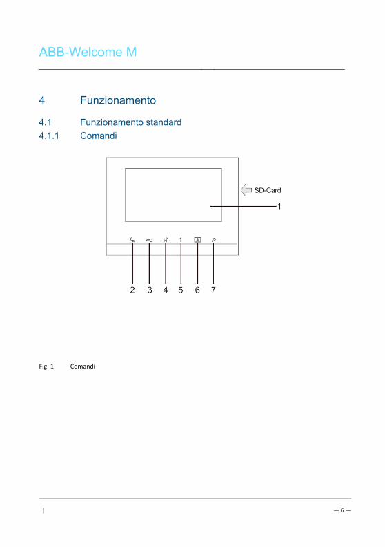
ABB-Welcome M
| — 6 —
Pos: 18 /DinA4 - Anleitungen Online/Ueberschriften/1./Bedienung @ 18\mod_1302613924165_15.docx @ 103365 @ 1 @ 1
4 Funzionamento Pos: 19 /DinA4 - Anleitungen Online/Ueberschriften/2./Normaler Betrieb @ 18\mod_1302768820965_15.docx @ 103540 @ 2 @ 1
4.1 Funzionamento standard Pos: 20 /DinA4 - Anleitungen Online/Ueberschriften/3./Bedienelemente @ 20\mod_1323260220559_15.docx @ 111647 @ 3 @ 1
4.1.1 Comandi Pos: 21 /DinA4 - Anleitungen Online/Inhalt/KNX/DoorEntry/83220-AP-xxx/Bedienelemente - 83220-AP-xxx @ 18\mod_1303212853605_15.docx @ 103673 @ @ 1
Fig. 1 Comandi
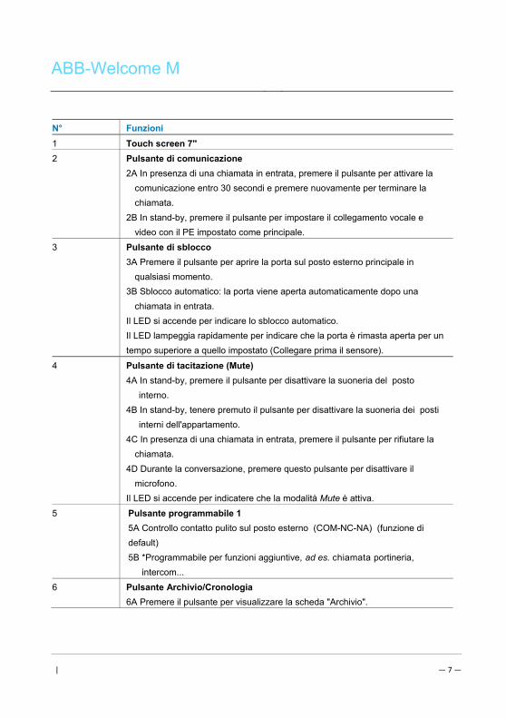
ABB-Welcome M
| — 7 —
N° Funzioni
1 Touch screen 7''
2 Pulsante di comunicazione
2A In presenza di una chiamata in entrata, premere il pulsante per attivare la
comunicazione entro 30 secondi e premere nuovamente per terminare la
chiamata.
2B In stand-by, premere il pulsante per impostare il collegamento vocale e
video con il PE impostato come principale.
3 Pulsante di sblocco
3A Premere il pulsante per aprire la porta sul posto esterno principale in
qualsiasi momento.
3B Sblocco automatico: la porta viene aperta automaticamente dopo una
chiamata in entrata.
Il LED si accende per indicare lo sblocco automatico.
Il LED lampeggia rapidamente per indicare che la porta è rimasta aperta per un
tempo superiore a quello impostato (Collegare prima il sensore).
4 Pulsante di tacitazione (Mute)
4A In stand-by, premere il pulsante per disattivare la suoneria del posto
interno.
4B In stand-by, tenere premuto il pulsante per disattivare la suoneria dei posti
interni dell'appartamento.
4C In presenza di una chiamata in entrata, premere il pulsante per rifiutare la
chiamata.
4D Durante la conversazione, premere questo pulsante per disattivare il
microfono.
Il LED si accende per indicatere che la modalità Mute è attiva.
5 Pulsante programmabile 1
5A Controllo contatto pulito sul posto esterno (COM-NC-NA) (funzione di
default)
5B *Programmabile per funzioni aggiuntive, ad es. chiamata portineria,
intercom...
6 Pulsante Archivio/Cronologia
6A Premere il pulsante per visualizzare la scheda "Archivio".
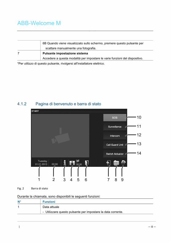
ABB-Welcome M
| — 8 —
6B Quando viene visualizzato sullo schermo, premere questo pulsante per
scattare manualmente una fotografia.
7 Pulsante impostazione sistema
Accedere a questa modalità per impostare le varie funzioni del dispositivo.
*Per utilizzo di questo pulsante, rivolgersi all'installatore elettrico.
4.1.2 Pagina di benvenuto e barra di stato
Fig. 2 Barra di stato
Durante la chiamata, sono disponibili le seguenti funzioni:
N° Funzioni
1 Data attuale
- Utilizzare questo pulsante per impostare la data corrente.
3 92 4 65 7 8
10
1
11
12
13
14
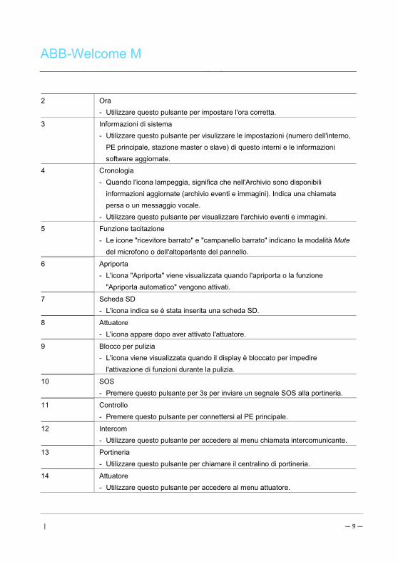
ABB-Welcome M
| — 9 —
2 Ora
- Utilizzare questo pulsante per impostare l'ora corretta.
3 Informazioni di sistema
- Utilizzare questo pulsante per visulizzare le impostazioni (numero dell'interno,
PE principale, stazione master o slave) di questo interni e le informazioni
software aggiornate.
4 Cronologia
- Quando l'icona lampeggia, significa che nell'Archivio sono disponibili
informazioni aggiornate (archivio eventi e immagini). Indica una chiamata
persa o un messaggio vocale.
- Utilizzare questo pulsante per visualizzare l'archivio eventi e immagini.
5 Funzione tacitazione
- Le icone "ricevitore barrato" e "campanello barrato" indicano la modalità Mute
del microfono o dell'altoparlante del pannello.
6 Apriporta
- L'icona "Apriporta" viene visualizzata quando l'apriporta o la funzione
"Apriporta automatico" vengono attivati.
7 Scheda SD
- L'icona indica se è stata inserita una scheda SD.
8 Attuatore
- L'icona appare dopo aver attivato l'attuatore.
9 Blocco per pulizia
- L'icona viene visualizzata quando il display è bloccato per impedire
l'attivazione di funzioni durante la pulizia.
10 SOS
- Premere questo pulsante per 3s per inviare un segnale SOS alla portineria.
11 Controllo
- Premere questo pulsante per connettersi al PE principale.
12 Intercom
- Utilizzare questo pulsante per accedere al menu chiamata intercomunicante.
13 Portineria
- Utilizzare questo pulsante per chiamare il centralino di portineria.
14 Attuatore
- Utilizzare questo pulsante per accedere al menu attuatore. Pos: 29 /Busch-Jaeger (Neustruktur)/Modul-Struktur/Online-Dokumentation/Steuermodule - Online-Dokumentation (--> Für alle Dokumente <--)/++++++++++++ Seitenumbruch ++++++++++++ @ 9\mod_1268898668093_0.docx @ 52149 @ @ 1
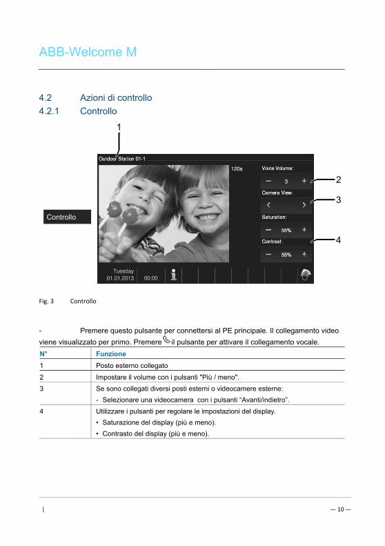
ABB-Welcome M
| — 10 —
Pos: 26 /DinA4 - Anleitungen Online/Ueberschriften/2./Bedienaktionen @ 20\mod_1323262294281_15.docx @ 111911 @ 2 @ 1
4.2 Azioni di controllo Pos: 27 /DinA4 - Anleitungen Online/Ueberschriften/3./Sprech- und Videoverbindung @ 20\mod_1323262368700_15.docx @ 111927 @ 3 @ 1
4.2.1 Controllo Pos: 28 /DinA4 - Anleitungen Online/Inhalt/KNX/DoorEntry/83220-AP-xxx/Sprech- und Videoverbindung - 83220-AP-xxx @ 20\mod_1323262341852_15.docx @ 111919 @ @ 1
Fig. 3 Controllo
- Premere questo pulsante per connettersi al PE principale. Il collegamento video
viene visualizzato per primo. Premere il pulsante per attivare il collegamento vocale.
N° Funzione
1 Posto esterno collegato
2 Impostare il volume con i pulsanti "Più / meno".
3 Se sono collegati diversi posti esterni o videocamere esterne:
- Selezionare una videocamera con i pulsanti “Avanti/indietro”.
4 Utilizzare i pulsanti per regolare le impostazioni del display.
• Saturazione del display (più e meno).
• Contrasto del display (più e meno). Pos: 29 /Busch-Jaeger (Neustruktur)/Modul-Struktur/Online-Dokumentation/Steuermodule - Online-Dokumentation (--> Für alle Dokumente <--)/++++++++++++ Seitenumbruch ++++++++++++ @ 9\mod_1268898668093_0.docx @ 52149 @ @ 1
2
3
4
1
Controllo
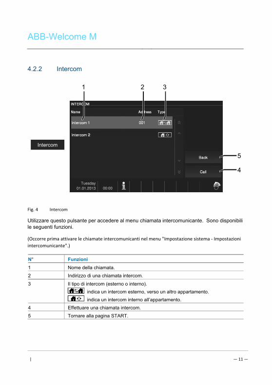
ABB-Welcome M
| — 11 —
Pos: 30 /DinA4 - Anleitungen Online/Ueberschriften/3./Tuer oeffnen @ 20\mod_1323263277453_15.docx @ 111935 @ 3 @ 1
4.2.2 Intercom Pos: 31 /DinA4 - Anleitungen Online/Inhalt/KNX/DoorEntry/83220-AP-xxx/Tuer oeffnen - 83220-AP-xxx @ 20\mod_1323267958479_15.docx @ 112109 @ @ 1
Fig. 4 Intercom
Utilizzare questo pulsante per accedere al menu chiamata intercomunicante. Sono disponibili le seguenti funzioni.
(Occorre prima attivare le chiamate intercomunicanti nel menu "Impostazione sistema ‐ Impostazioni
intercomunicante".)
N° Funzioni
1 Nome della chiamata.
2 Indirizzo di una chiamata intercom.
3 Il tipo di intercom (esterno o interno).
indica un intercom esterno, verso un altro appartamento.
indica un intercom interno all’appartamento.
4 Effettuare una chiamata intercom.
5 Tornare alla pagina START.
4
1
Intercom
5
2 3
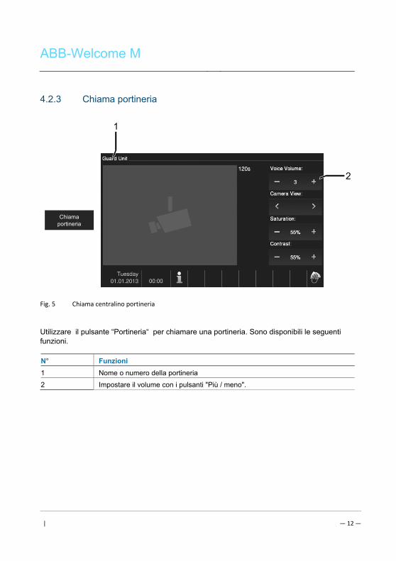
ABB-Welcome M
| — 12 —
4.2.3 Chiama portineria Pos: 31 /DinA4 - Anleitungen Online/Inhalt/KNX/DoorEntry/83220-AP-xxx/Tuer oeffnen - 83220-AP-xxx @ 20\mod_1323267958479_15.docx @ 112109 @ @ 1
Fig. 5 Chiama centralino portineria
Utilizzare il pulsante “Portineria“ per chiamare una portineria. Sono disponibili le seguenti funzioni.
N° Funzioni
1 Nome o numero della portineria
2 Impostare il volume con i pulsanti "Più / meno".
Chiama portineria
2
1
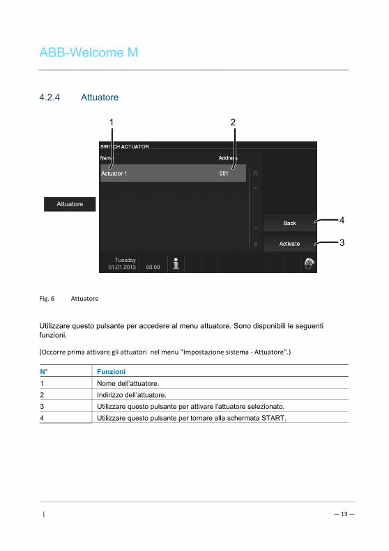
ABB-Welcome M
| — 13 —
4.2.4 Attuatore Pos: 31 /DinA4 - Anleitungen Online/Inhalt/KNX/DoorEntry/83220-AP-xxx/Tuer oeffnen - 83220-AP-xxx @ 20\mod_1323267958479_15.docx @ 112109 @ @ 1
Fig. 6 Attuatore
Utilizzare questo pulsante per accedere al menu attuatore. Sono disponibili le seguenti funzioni.
(Occorre prima attivare gli attuatori nel menu "Impostazione sistema ‐ Attuatore".)
N° Funzioni
1 Nome dell’attuatore.
2 Indirizzo dell’attuatore.
3 Utilizzare questo pulsante per attivare l'attuatore selezionato.
4 Utilizzare questo pulsante per tornare alla schermata START.
Attuatore
4
1 2
3
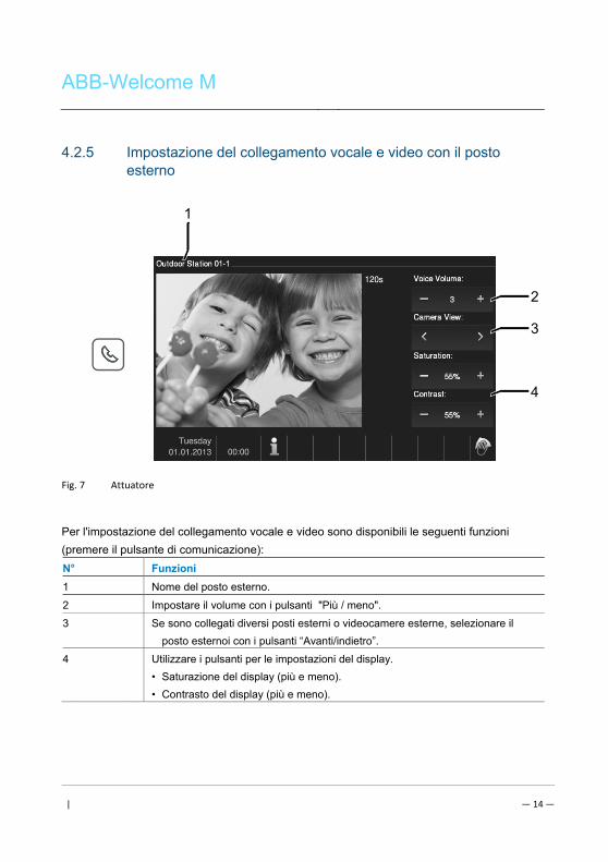
ABB-Welcome M
| — 14 —
4.2.5 Impostazione del collegamento vocale e video con il posto esterno
Pos: 31 /DinA4 - Anleitungen Online/Inhalt/KNX/DoorEntry/83220-AP-xxx/Tuer oeffnen - 83220-AP-xxx @ 20\mod_1323267958479_15.docx @ 112109 @ @ 1
Fig. 7 Attuatore
Per l'impostazione del collegamento vocale e video sono disponibili le seguenti funzioni
(premere il pulsante di comunicazione):
N° Funzioni
1 Nome del posto esterno.
2 Impostare il volume con i pulsanti "Più / meno".
3 Se sono collegati diversi posti esterni o videocamere esterne, selezionare il
posto esternoi con i pulsanti “Avanti/indietro”.
4 Utilizzare i pulsanti per le impostazioni del display.
• Saturazione del display (più e meno).
• Contrasto del display (più e meno). Pos: 29 /Busch-Jaeger (Neustruktur)/Modul-Struktur/Online-Dokumentation/Steuermodule - Online-Dokumentation (--> Für alle Dokumente <--)/++++++++++++ Seitenumbruch ++++++++++++ @ 9\mod_1268898668093_0.docx @ 52149 @ @ 1
2
3
4
1
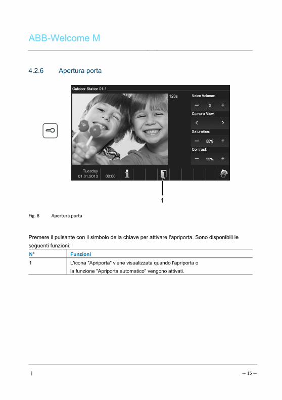
ABB-Welcome M
| — 15 —
4.2.6 Apertura porta Pos: 31 /DinA4 - Anleitungen Online/Inhalt/KNX/DoorEntry/83220-AP-xxx/Tuer oeffnen - 83220-AP-xxx @ 20\mod_1323267958479_15.docx @ 112109 @ @ 1
Fig. 8 Apertura porta
Premere il pulsante con il simbolo della chiave per attivare l'apriporta. Sono disponibili le
seguenti funzioni:
N° Funzioni
1 L'icona "Apriporta" viene visualizzata quando l'apriporta o
la funzione "Apriporta automatico" vengono attivati.
1
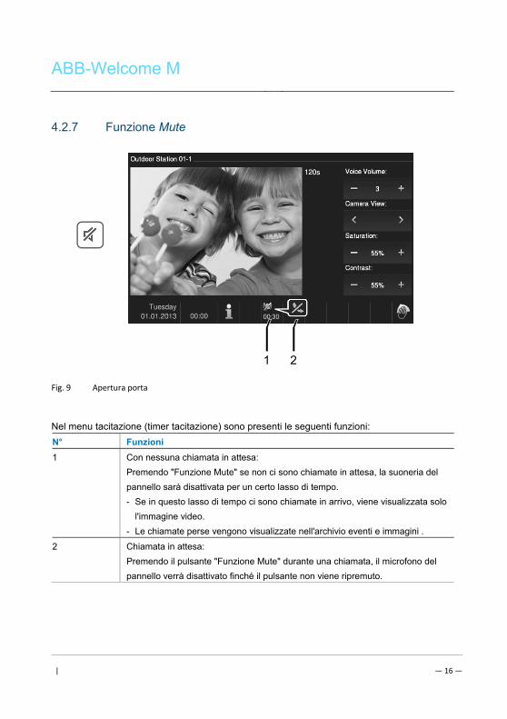
ABB-Welcome M
| — 16 —
4.2.7 Funzione Mute Pos: 31 /DinA4 - Anleitungen Online/Inhalt/KNX/DoorEntry/83220-AP-xxx/Tuer oeffnen - 83220-AP-xxx @ 20\mod_1323267958479_15.docx @ 112109 @ @ 1
Fig. 9 Apertura porta
Nel menu tacitazione (timer tacitazione) sono presenti le seguenti funzioni:
N° Funzioni
1 Con nessuna chiamata in attesa:
Premendo "Funzione Mute" se non ci sono chiamate in attesa, la suoneria del
pannello sarà disattivata per un certo lasso di tempo.
- Se in questo lasso di tempo ci sono chiamate in arrivo, viene visualizzata solo
l'immagine video.
- Le chiamate perse vengono visualizzate nell'archivio eventi e immagini .
2 Chiamata in attesa:
Premendo il pulsante "Funzione Mute" durante una chiamata, il microfono del
pannello verrà disattivato finché il pulsante non viene ripremuto.
1 2
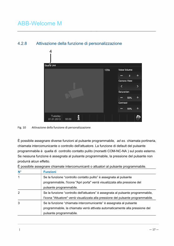
ABB-Welcome M
| — 17 —
4.2.8 Attivazione della funzione di personalizzazione Pos: 31 /DinA4 - Anleitungen Online/Inhalt/KNX/DoorEntry/83220-AP-xxx/Tuer oeffnen - 83220-AP-xxx @ 20\mod_1323267958479_15.docx @ 112109 @ @ 1
Fig. 10 Attivazione della funzione di personalizzazione
È possibile assegnare diverse funzioni al pulsante programmabile, ad es. chiamata portineria,
chiamata intercomunicante o controllo dell'attuatore. La funzione di default del pulsante
programmabile è quella di controllo contatto pulito (morsetti COM-NC-NA ) sul posto esterno.
Se nessuna funzione è assegnata al pulsante programmabile, la pressione del pulsante non
produrrà alcun effetto.
È possibile assegnare chiamate intercomunicanti o attuatori al pulsante programmabile.
N° Funzioni
1 Se la funzione “controllo contatto pulito” è assegnata al pulsante
programmabile, l'icona "Apri porta" verrà visualizzata alla pressione del
pulsante programmabile.
2 Se la funzione “controllo dell'attuatore” è assegnata al pulsante programmabile,
l'icona "Attuatore" verrà visualizzata alla pressione del pulsante programmabile.
3 Se la funzione “chiamata intercomunicante” è assegnata al pulsante
programmabile, la chiamata verrà attivata automaticamente alla pressione del
pulsante programmabile.
4
ABB-Welcome M
| — 18 —
4 Se la funzione “chiama centralino di portineria” è assegnata al pulsante
programmabile, la chiamata verrà attivata automaticamente alla pressione del
pulsante programmabile.
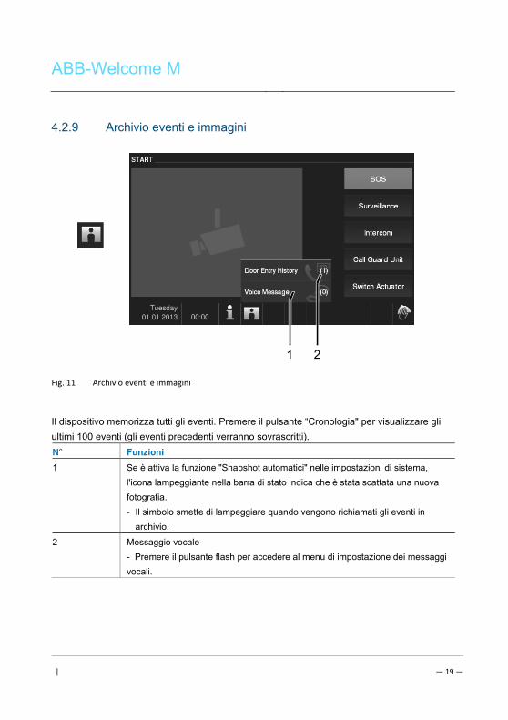
ABB-Welcome M
| — 19 —
4.2.9 Archivio eventi e immagini Pos: 31 /DinA4 - Anleitungen Online/Inhalt/KNX/DoorEntry/83220-AP-xxx/Tuer oeffnen - 83220-AP-xxx @ 20\mod_1323267958479_15.docx @ 112109 @ @ 1
Fig. 11 Archivio eventi e immagini
Il dispositivo memorizza tutti gli eventi. Premere il pulsante “Cronologia" per visualizzare gli
ultimi 100 eventi (gli eventi precedenti verranno sovrascritti).
N° Funzioni
1 Se è attiva la funzione "Snapshot automatici" nelle impostazioni di sistema,
l'icona lampeggiante nella barra di stato indica che è stata scattata una nuova
fotografia.
- Il simbolo smette di lampeggiare quando vengono richiamati gli eventi in
archivio.
2 Messaggio vocale
- Premere il pulsante flash per accedere al menu di impostazione dei messaggi
vocali.
1 2
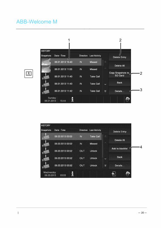
ABB-Welcome M
| — 20 —
1 2
2
3
4
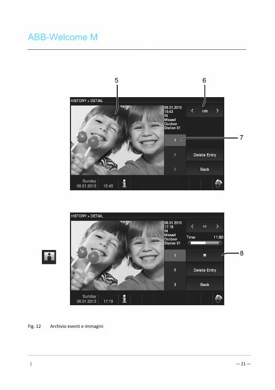
ABB-Welcome M
| — 21 —
Fig. 12 Archivio eventi e immagini
8
5 6
7
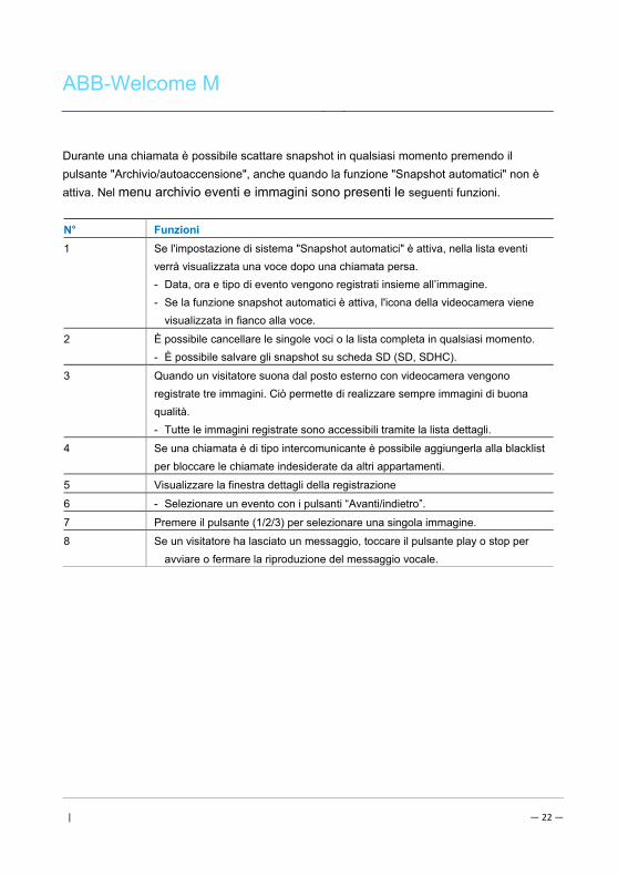
ABB-Welcome M
| — 22 —
Durante una chiamata è possibile scattare snapshot in qualsiasi momento premendo il
pulsante "Archivio/autoaccensione", anche quando la funzione "Snapshot automatici" non è
attiva. Nel menu archivio eventi e immagini sono presenti le seguenti funzioni.
N° Funzioni
1 Se l'impostazione di sistema "Snapshot automatici" è attiva, nella lista eventi
verrà visualizzata una voce dopo una chiamata persa.
- Data, ora e tipo di evento vengono registrati insieme all’immagine.
- Se la funzione snapshot automatici è attiva, l'icona della videocamera viene
visualizzata in fianco alla voce.
2 È possibile cancellare le singole voci o la lista completa in qualsiasi momento.
- È possibile salvare gli snapshot su scheda SD (SD, SDHC).
3 Quando un visitatore suona dal posto esterno con videocamera vengono
registrate tre immagini. Ciò permette di realizzare sempre immagini di buona
qualità.
- Tutte le immagini registrate sono accessibili tramite la lista dettagli.
4 Se una chiamata è di tipo intercomunicante è possibile aggiungerla alla blacklist
per bloccare le chiamate indesiderate da altri appartamenti.
5 Visualizzare la finestra dettagli della registrazione
6 - Selezionare un evento con i pulsanti “Avanti/indietro”.
7 Premere il pulsante (1/2/3) per selezionare una singola immagine.
8 Se un visitatore ha lasciato un messaggio, toccare il pulsante play o stop per
avviare o fermare la riproduzione del messaggio vocale.
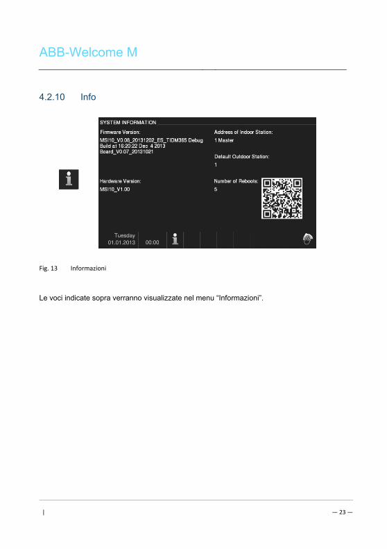
ABB-Welcome M
| — 23 —
4.2.10 Info Pos: 31 /DinA4 - Anleitungen Online/Inhalt/KNX/DoorEntry/83220-AP-xxx/Tuer oeffnen - 83220-AP-xxx @ 20\mod_1323267958479_15.docx @ 112109 @ @ 1
Fig. 13 Informazioni
Le voci indicate sopra verranno visualizzate nel menu “Informazioni”.
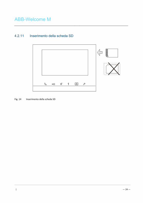
ABB-Welcome M
| — 24 —
4.2.11 Inserimento della scheda SD Pos: 31 /DinA4 - Anleitungen Online/Inhalt/KNX/DoorEntry/83220-AP-xxx/Tuer oeffnen - 83220-AP-xxx @ 20\mod_1323267958479_15.docx @ 112109 @ @ 1
Fig. 14 Inserimento della scheda SD
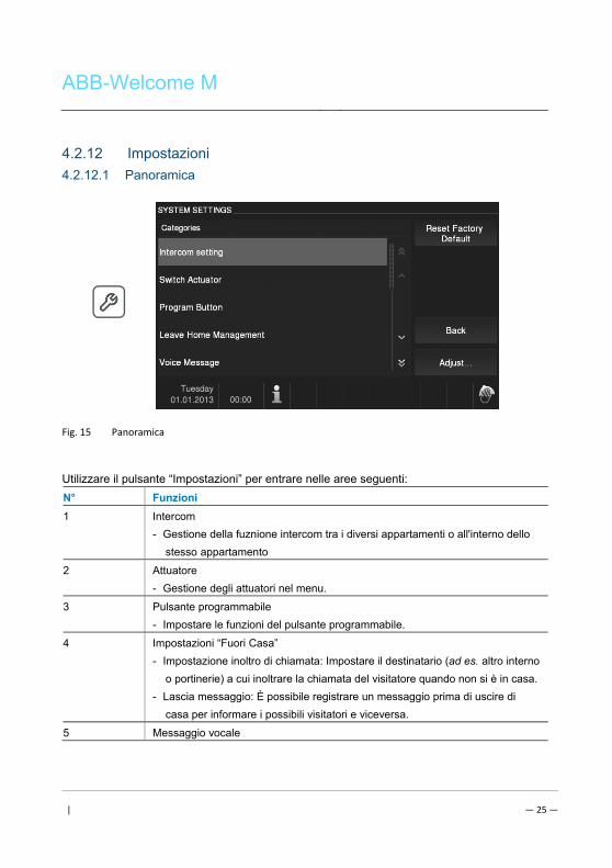
ABB-Welcome M
| — 25 —
4.2.12 Impostazioni Pos: 31 /DinA4 - Anleitungen Online/Inhalt/KNX/DoorEntry/83220-AP-xxx/Tuer oeffnen - 83220-AP-xxx @ 20\mod_1323267958479_15.docx @ 112109 @ @ 1
4.2.12.1 Panoramica
Fig. 15 Panoramica
Utilizzare il pulsante “Impostazioni” per entrare nelle aree seguenti:
N° Funzioni
1 Intercom
- Gestione della fuznione intercom tra i diversi appartamenti o all'interno dello
stesso appartamento
2 Attuatore
- Gestione degli attuatori nel menu.
3 Pulsante programmabile
- Impostare le funzioni del pulsante programmabile.
4 Impostazioni “Fuori Casa”
- Impostazione inoltro di chiamata: Impostare il destinatario (ad es. altro interno
o portinerie) a cui inoltrare la chiamata del visitatore quando non si è in casa.
- Lascia messaggio: È possibile registrare un messaggio prima di uscire di
casa per informare i possibili visitatori e viceversa.
5 Messaggio vocale
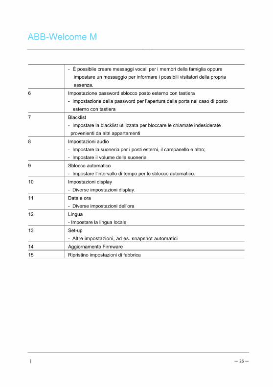
ABB-Welcome M
| — 26 —
- È possibile creare messaggi vocali per i membri della famiglia oppure
impostare un messaggio per informare i possibili visitatori della propria
assenza.
6 Impostazione password sblocco posto esterno con tastiera
- Impostazione della password per l’apertura della porta nel caso di posto
esterno con tastiera
7 Blacklist
- Impostare la blacklist utilizzata per bloccare le chiamate indesiderate
provenienti da altri appartamenti
8 Impostazioni audio
- Impostare la suoneria per i posti esterni, il campanello e altro;
- Impostare il volume della suoneria
9 Sblocco automatico
- Impostare l'intervallo di tempo per lo sblocco automatico.
10 Impostazioni display
- Diverse impostazioni display.
11 Data e ora
- Diverse impostazioni dell'ora
12 Lingua
- Impostare la lingua locale
13 Set-up
- Altre impostazioni, ad es. snapshot automatici
14 Aggiornamento Firmware
15 Ripristino impostazioni di fabbrica
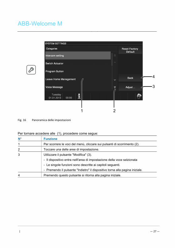
ABB-Welcome M
| — 27 —
Fig. 16 Panoramica delle impostazioni
Per tornare accedere alle (1), procedere come segue:
N° Funzione
1 Per scorrere le voci del menù, cliccare sui pulsanti di scorrimento (2).
2 Toccare una delle aree di impostazione.
3 Utilizzare il pulsante "Modifica" (3).
- Il dispositivo entra nelll'area di impostazione della voce selzionata
- Le singole funzioni sono descritte ai capitoli seguenti.
- Premendo il pulsante "Indietro" il dispositivo torna alla pagina iniziale.
4 Premendo questo pulsante si ritorna alla pagina iniziale.
4
1 2
3
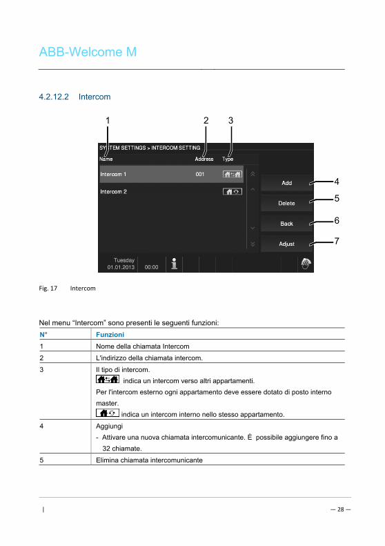
ABB-Welcome M
| — 28 —
4.2.12.2 Intercom
Fig. 17 Intercom
Nel menu “Intercom” sono presenti le seguenti funzioni:
N° Funzioni
1 Nome della chiamata Intercom
2 L'indirizzo della chiamata intercom.
3 Il tipo di intercom.
indica un intercom verso altri appartamenti.
Per l'intercom esterno ogni appartamento deve essere dotato di posto interno
master.
indica un intercom interno nello stesso appartamento.
4 Aggiungi
- Attivare una nuova chiamata intercomunicante. È possibile aggiungere fino a
32 chiamate.
5 Elimina chiamata intercomunicante
4
5
1 32
6
7
ABB-Welcome M
| — 29 —
- Cliccare su questo pulsante per eliminare un intercom esistente. Infine
confermare sull casella visualizzata.
6 Indietro
- Cliccare su questo pulsante per tornare al menu delle impostazioni di
sistema.
7 Regolazione
- Cliccare su questo pulsante per modificare le impostazioni di una chiamata
intercom.
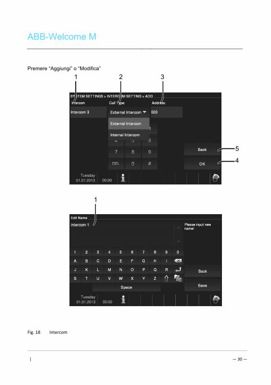
ABB-Welcome M
| — 30 —
Premere “Aggiungi” o “Modifica”
Fig. 18 Intercom
5
4
1 32
1
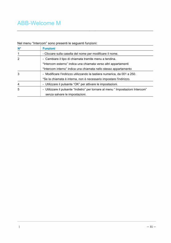
ABB-Welcome M
| — 31 —
Nel menu “Intercom” sono presenti le seguenti funzioni:
N° Funzioni
1 - Cliccare sulla casella del nome per modificare il nome.
2 - Cambiare il tipo di chiamata tramite menu a tendina.
*Intercom esterno” indica una chiamata verso altri appartamenti
*Intercom interno” indica una chiamata nello stesso appartamento
3 - Modificare l'indirizzo utilizzando la tastiera numerica, da 001 a 250.
*Se la chiamata è interna, non è necessario impostare l'indirizzo.
4 - Utilizzare il pulsante “OK” per attivare le impostazioni.
5 - Utilizzare il pulsante “Indietro” per tornare al menu “ Impostazioni Intercom”
senza salvare le impostazioni.
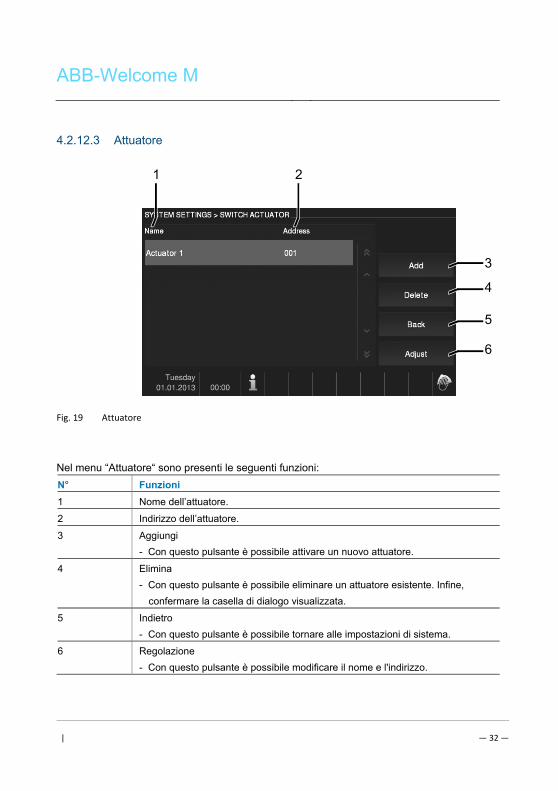
ABB-Welcome M
| — 32 —
4.2.12.3 Attuatore
Fig. 19 Attuatore
Nel menu “Attuatore“ sono presenti le seguenti funzioni:
N° Funzioni
1 Nome dell’attuatore.
2 Indirizzo dell’attuatore.
3 Aggiungi
- Con questo pulsante è possibile attivare un nuovo attuatore.
4 Elimina
- Con questo pulsante è possibile eliminare un attuatore esistente. Infine,
confermare la casella di dialogo visualizzata.
5 Indietro
- Con questo pulsante è possibile tornare alle impostazioni di sistema.
6 Regolazione
- Con questo pulsante è possibile modificare il nome e l'indirizzo.
3
4
1 2
5
6
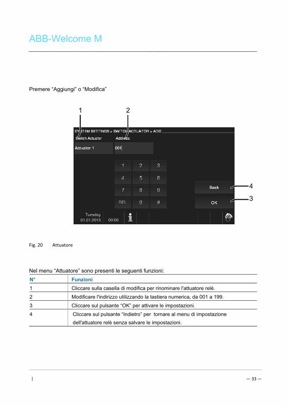
ABB-Welcome M
| — 33 —
Premere “Aggiungi” o “Modifica”
Fig. 20 Attuatore
Nel menu “Attuatore” sono presenti le seguenti funzioni:
N° Funzioni
1 Cliccare sulla casella di modifica per rinominare l'attuatore relè.
2 Modificare l'indirizzo utilizzando la tastiera numerica, da 001 a 199.
3 Cliccare sul pulsante “OK” per attivare le impostazioni.
4 Cliccare sul pulsante “Indietro” per tornare al menu di impostazione
dell'attuatore relè senza salvare le impostazioni.
4
3
1 2
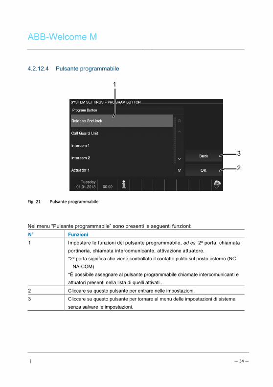
ABB-Welcome M
| — 34 —
4.2.12.4 Pulsante programmabile
Fig. 21 Pulsante programmabile
Nel menu “Pulsante programmabile” sono presenti le seguenti funzioni:
N° Funzioni
1 Impostare le funzioni del pulsante programmabile, ad es. 2a porta, chiamata
portineria, chiamata intercomunicante, attivazione attuatore.
*2a porta significa che viene controllato il contatto pulito sul posto esterno (NC-
NA-COM)
*È possibile assegnare al pulsante programmabile chiamate intercomunicanti e
attuatori presenti nella lista di quelli attivati .
2 Cliccare su questo pulsante per entrare nelle impostazioni.
3 Cliccare su questo pulsante per tornare al menu delle impostazioni di sistema
senza salvare le impostazioni.
3
2
1
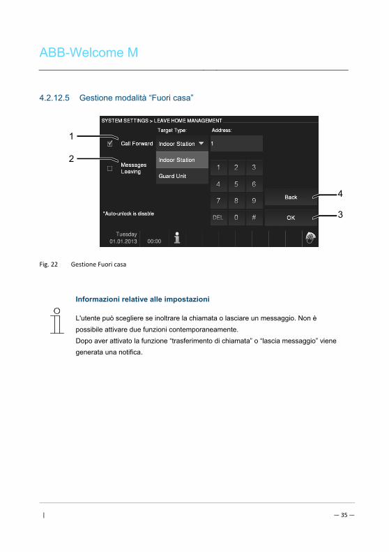
ABB-Welcome M
| — 35 —
4.2.12.5 Gestione modalità “Fuori casa”
Fig. 22 Gestione Fuori casa
Informazioni relative alle impostazioni
L'utente può scegliere se inoltrare la chiamata o lasciare un messaggio. Non è
possibile attivare due funzioni contemporaneamente.
Dopo aver attivato la funzione “trasferimento di chiamata” o “lascia messaggio” viene
generata una notifica.
4
3
1
2
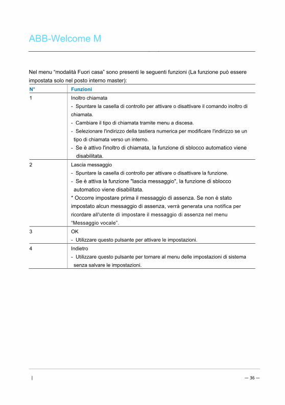
ABB-Welcome M
| — 36 —
Nel menu “modalità Fuori casa” sono presenti le seguenti funzioni (La funzione può essere
impostata solo nel posto interno master):
N° Funzioni
1 Inoltro chiamata
- Spuntare la casella di controllo per attivare o disattivare il comando inoltro di
chiamata.
- Cambiare il tipo di chiamata tramite menu a discesa.
- Selezionare l'indirizzo della tastiera numerica per modificare l'indirizzo se un
tipo di chiamata verso un interno.
- Se è attivo l'inoltro di chiamata, la funzione di sblocco automatico viene
disabilitata.
2 Lascia messaggio
- Spuntare la casella di controllo per attivare o disattivare la funzione.
- Se è attiva la funzione "lascia messaggio", la funzione di sblocco
automatico viene disabilitata.
* Occorre impostare prima il messaggio di assenza. Se non è stato
impostato alcun messaggio di assenza, verrà generata una notifica per
ricordare all'utente di impostare il messaggio di assenza nel menu
“Messaggio vocale”.
3 OK
- Utilizzare questo pulsante per attivare le impostazioni.
4 Indietro
- Utilizzare questo pulsante per tornare al menu delle impostazioni di sistema
senza salvare le impostazioni.
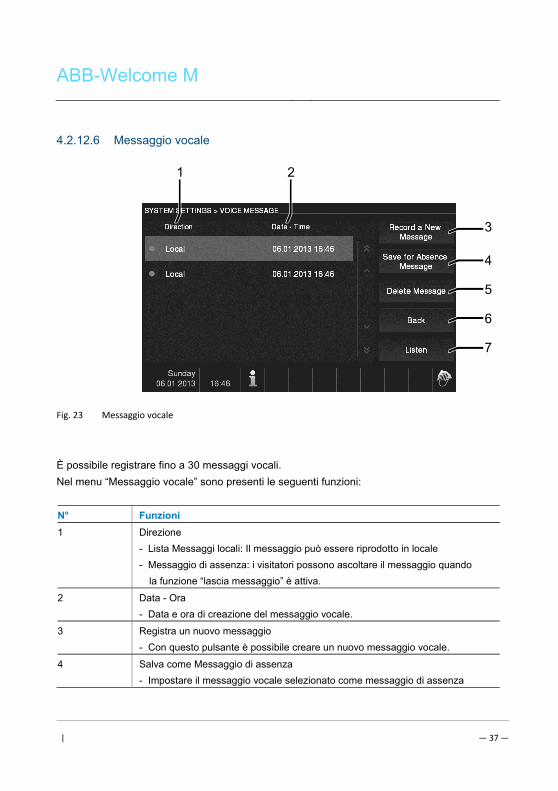
ABB-Welcome M
| — 37 —
4.2.12.6 Messaggio vocale
Fig. 23 Messaggio vocale
È possibile registrare fino a 30 messaggi vocali.
Nel menu “Messaggio vocale” sono presenti le seguenti funzioni:
N° Funzioni
1 Direzione
- Lista Messaggi locali: Il messaggio può essere riprodotto in locale
- Messaggio di assenza: i visitatori possono ascoltare il messaggio quando
la funzione “lascia messaggio” è attiva.
2 Data - Ora
- Data e ora di creazione del messaggio vocale.
3 Registra un nuovo messaggio
- Con questo pulsante è possibile creare un nuovo messaggio vocale.
4 Salva come Messaggio di assenza
- Impostare il messaggio vocale selezionato come messaggio di assenza
6
7
1 2
3
4
5
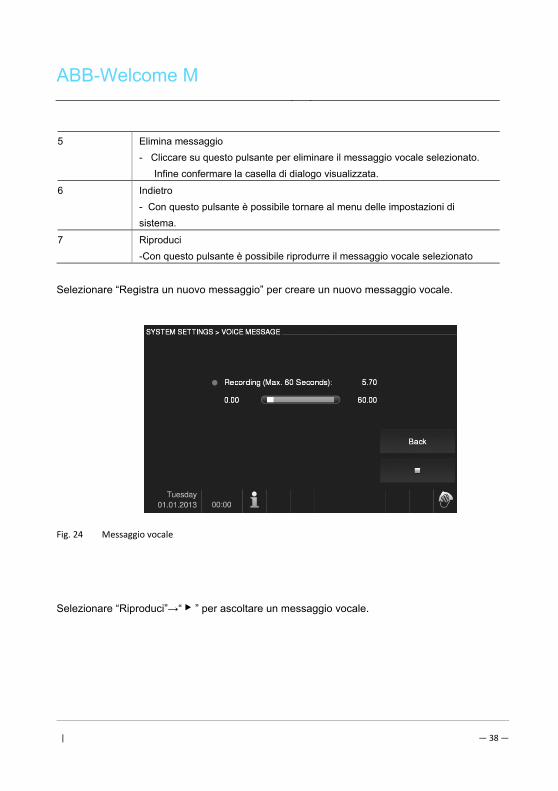
ABB-Welcome M
| — 38 —
5 Elimina messaggio
- Cliccare su questo pulsante per eliminare il messaggio vocale selezionato.
Infine confermare la casella di dialogo visualizzata.
6 Indietro
- Con questo pulsante è possibile tornare al menu delle impostazioni di
sistema.
7 Riproduci
-Con questo pulsante è possibile riprodurre il messaggio vocale selezionato
Selezionare “Registra un nuovo messaggio” per creare un nuovo messaggio vocale.
Fig. 24 Messaggio vocale
Selezionare “Riproduci”→“ ▶ ” per ascoltare un messaggio vocale.

ABB-Welcome M
| — 39 —
Fig. 25 Messaggio vocale
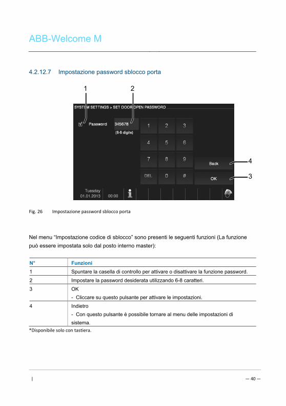
ABB-Welcome M
| — 40 —
4.2.12.7 Impostazione password sblocco porta
Fig. 26 Impostazione password sblocco porta
Nel menu “Impostazione codice di sblocco” sono presenti le seguenti funzioni (La funzione
può essere impostata solo dal posto interno master):
N° Funzioni
1 Spuntare la casella di controllo per attivare o disattivare la funzione password.
2 Impostare la password desiderata utilizzando 6-8 caratteri.
3 OK
- Cliccare su questo pulsante per attivare le impostazioni.
4 Indietro
- Con questo pulsante è possibile tornare al menu delle impostazioni di
sistema.
*Disponibile solo con tastiera.
4
3
21
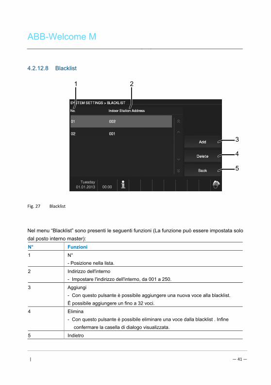
ABB-Welcome M
| — 41 —
4.2.12.8 Blacklist
Fig. 27 Blacklist
Nel menu “Blacklist” sono presenti le seguenti funzioni (La funzione può essere impostata solo
dal posto interno master):
N° Funzioni
1 N°
- Posizione nella lista.
2 Indirizzo dell'interno
- Impostare l'indirizzo dell'interno, da 001 a 250.
3 Aggiungi
- Con questo pulsante è possibile aggiungere una nuova voce alla blacklist.
È possibile aggiungere un fino a 32 voci.
4 Elimina
- Con questo pulsante è possibile eliminare una voce dalla blacklist . Infine
confermare la casella di dialogo visualizzata.
5 Indietro
4
5
1 2
3
ABB-Welcome M
| — 42 —
- Con questo pulsante è possibile tornare al menu delle impostazioni di
sistema.
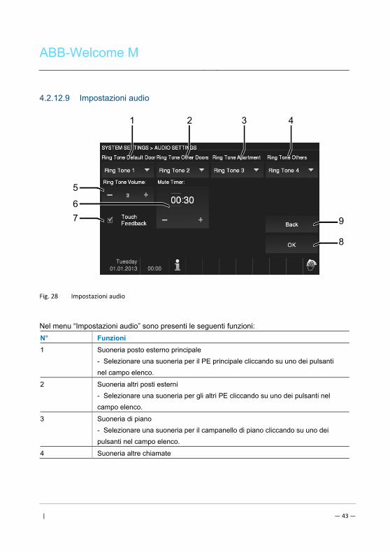
ABB-Welcome M
| — 43 —
4.2.12.9 Impostazioni audio
Fig. 28 Impostazioni audio
Nel menu “Impostazioni audio” sono presenti le seguenti funzioni:
N° Funzioni
1 Suoneria posto esterno principale
- Selezionare una suoneria per il PE principale cliccando su uno dei pulsanti
nel campo elenco.
2 Suoneria altri posti esterni
- Selezionare una suoneria per gli altri PE cliccando su uno dei pulsanti nel
campo elenco.
3 Suoneria di piano
- Selezionare una suoneria per il campanello di piano cliccando su uno dei
pulsanti nel campo elenco.
4 Suoneria altre chiamate
9
8
1 2
5
3 4
6 7
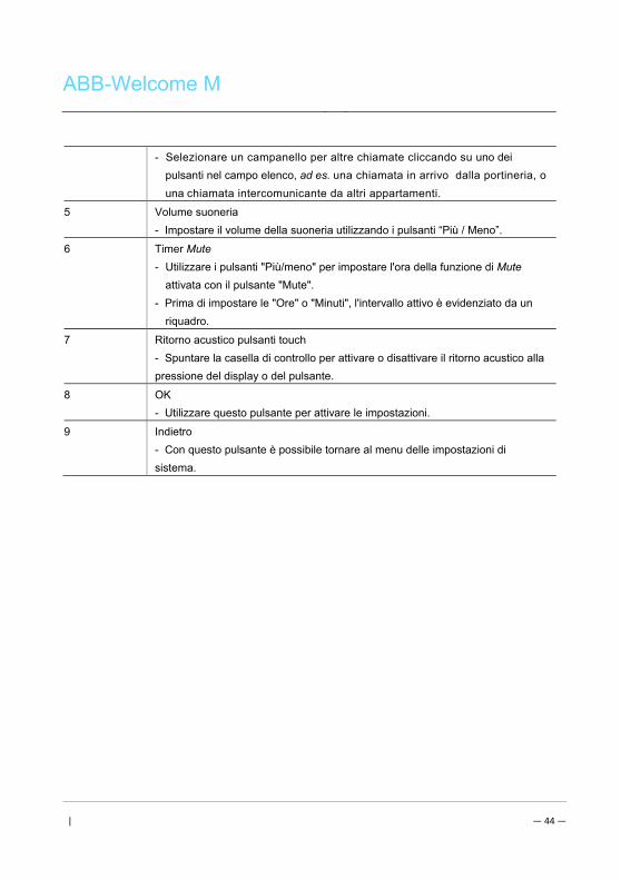
ABB-Welcome M
| — 44 —
- Selezionare un campanello per altre chiamate cliccando su uno dei
pulsanti nel campo elenco, ad es. una chiamata in arrivo dalla portineria, o
una chiamata intercomunicante da altri appartamenti.
5 Volume suoneria
- Impostare il volume della suoneria utilizzando i pulsanti “Più / Meno”.
6 Timer Mute
- Utilizzare i pulsanti "Più/meno" per impostare l'ora della funzione di Mute
attivata con il pulsante "Mute".
- Prima di impostare le "Ore" o "Minuti", l'intervallo attivo è evidenziato da un
riquadro.
7 Ritorno acustico pulsanti touch
- Spuntare la casella di controllo per attivare o disattivare il ritorno acustico alla
pressione del display o del pulsante.
8 OK
- Utilizzare questo pulsante per attivare le impostazioni.
9 Indietro
- Con questo pulsante è possibile tornare al menu delle impostazioni di
sistema.
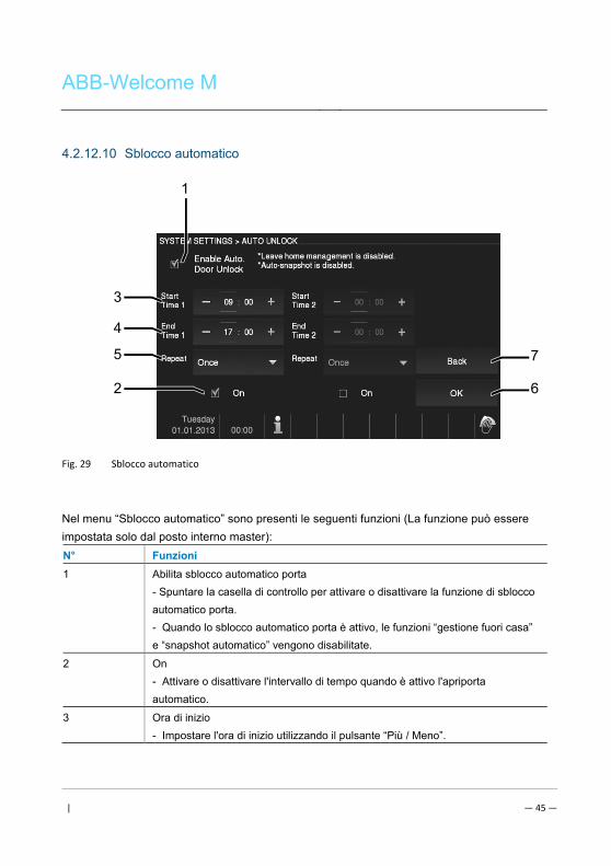
ABB-Welcome M
| — 45 —
4.2.12.10 Sblocco automatico
Fig. 29 Sblocco automatico
Nel menu “Sblocco automatico” sono presenti le seguenti funzioni (La funzione può essere
impostata solo dal posto interno master):
N° Funzioni
1 Abilita sblocco automatico porta
- Spuntare la casella di controllo per attivare o disattivare la funzione di sblocco
automatico porta.
- Quando lo sblocco automatico porta è attivo, le funzioni “gestione fuori casa”
e “snapshot automatico” vengono disabilitate.
2 On
- Attivare o disattivare l'intervallo di tempo quando è attivo l'apriporta
automatico.
3 Ora di inizio
- Impostare l'ora di inizio utilizzando il pulsante “Più / Meno”.
7
6
3
1
4
5
2
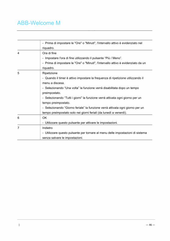
ABB-Welcome M
| — 46 —
- Prima di impostare le "Ore" o "Minuti", l'intervallo attivo è evidenziato nel
riquadro.
4 Ora di fine
- Impostare l'ora di fine utilizzando il pulsante “Più / Meno”.
- Prima di impostare le "Ore" o "Minuti", l'intervallo attivo è evidenziato da un
riquadro.
5 Ripetizione
- Quando il timer è attivo impostare la frequenza di ripetizione utilizzando il
menu a discesa.
- Selezionando “Una volta” la funzione verrà disabilitata dopo un tempo
preimpostato.
- Selezionando “Tutti i giorni” la funzione verrà attivata ogni giorno per un
tempo preimpostato.
- Selezionando “Giorno feriale” la funzione verrà attivata ogni giorno per un
tempo preimpostato solo nei giorni feriali (da lunedì a venerdì).
6 OK
- Utilizzare questo pulsante per attivare le impostazioni.
7 Indietro
- Utilizzare questo pulsante per tornare al menu delle impostazioni di sistema
senza salvare le impostazioni.
Pos: 32 /Busch-Jaeger (Neustruktur)/Modul-Struktur/Online-Dokumentation/Steuermodule - Online-Dokumentation (--> Für alle Dokumente <--)/++++++++++++ Seitenumbruch ++++++++++++ @ 9\mod_1268898668093_0.docx @ 52149 @ @ 1
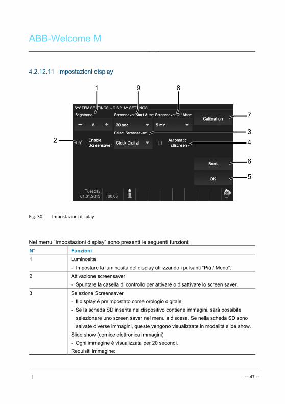
ABB-Welcome M
| — 47 —
4.2.12.11 Impostazioni display
Fig. 30 Impostazioni display
Nel menu “Impostazioni display” sono presenti le seguenti funzioni:
N° Funzioni
1 Luminosità
- Impostare la luminosità del display utilizzando i pulsanti “Più / Meno”.
2 Attivazione screensaver
- Spuntare la casella di controllo per attivare o disattivare lo screen saver.
3 Selezione Screensaver
- Il display è preimpostato come orologio digitale
- Se la scheda SD inserita nel dispositivo contiene immagini, sarà possibile
selezionare uno screen saver nel menu a discesa. Se nella scheda SD sono
salvate diverse immagini, queste vengono visualizzate in modalità slide show.
Slide show (cornice elettronica immagini)
- Ogni immagine è visualizzata per 20 secondi.
Requisiti immagine:
6
5
1 9 8
7
2 3 4
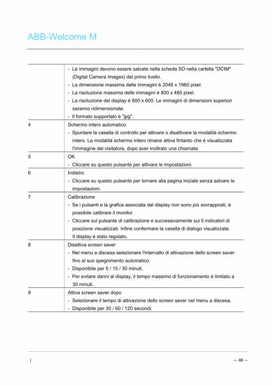
ABB-Welcome M
| — 48 —
- Le immagini devono essere salvate nella scheda SD nella cartella "DCIM"
(Digital Camera Images) del primo livello.
- La dimensione massima delle immagini è 2048 x 1960 pixel.
- La risoluzione massima delle immagini è 800 x 480 pixel.
- La risoluzione del display è 800 x 600. Le immagini di dimensioni superiori
saranno ridimensionate.
- Il formato supportato è "jpg".
4 Schermo intero automatico
- Spuntare la casella di controllo per attivare o disattivare la modalità schermo
intero. La modalità schermo intero rimane attiva fintanto che è visualizzata
l'immagine del visitatore, dopo aver inoltrato una chiamata
5 OK
- Cliccare su questo pulsante per attivare le impostazioni.
6 Indietro
- Cliccare su questo pulsante per tornare alla pagina iniziale senza salvare le
impostazioni.
7 Calibrazione
- Se i pulsanti e la grafica associata del display non sono più sovrapposti, è
possibile calibrare il monitor.
- Cliccare sul pulsante di calibrazione e successivamente sui 5 indicatori di
posizione visualizzati. Infine confermare la casella di dialogo visualizzata.
Il display è stato regolato.
8 Disattiva screen saver
- Nel menu a discesa selezionare l'intervallo di attivazione dello screen saver
fino al suo spegnimento automatico.
- Disponibile per 5 / 15 / 30 minuti.
- Per evitare danni al display, il tempo massimo di funzionamento è limitato a
30 minuti.
9 Attiva screen saver dopo
- Selezionare il tempo di attivazione dello screen saver nel menu a discesa.
- Disponibile per 30 / 60 / 120 secondi.
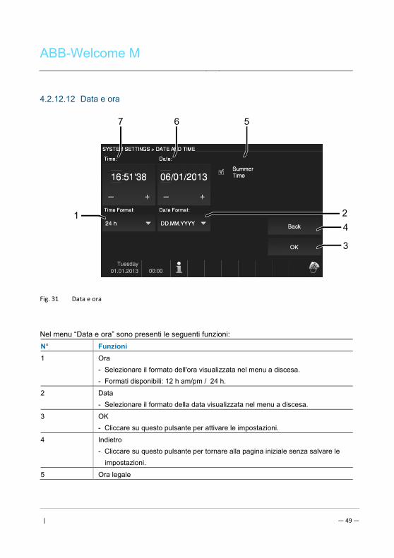
ABB-Welcome M
| — 49 —
4.2.12.12 Data e ora
Fig. 31 Data e ora
Nel menu “Data e ora” sono presenti le seguenti funzioni:
N° Funzioni
1 Ora
- Selezionare il formato dell'ora visualizzata nel menu a discesa.
- Formati disponibili: 12 h am/pm / 24 h.
2 Data
- Selezionare il formato della data visualizzata nel menu a discesa.
3 OK
- Cliccare su questo pulsante per attivare le impostazioni.
4 Indietro
- Cliccare su questo pulsante per tornare alla pagina iniziale senza salvare le
impostazioni.
5 Ora legale
4
3
7 6 5
1 2
ABB-Welcome M
| — 50 —
- Spuntare la casella di controllo per attivare o disattivare l'ora legale
(commutazione automatica).
6 Data
- Impostare la data utilizzando i pulsanti "Più / Meno".
- Impostare "Giorno", "Mese" o "Anno". L'area attiva è evidenziata da un
riquadro.
7 Ora
- Impostare l'ora utilizzando i pulsanti "Più / Meno".
- Prima di impostare le "Ore", i "Minuti" o i "Secondi" l'area attiva è evidenziata
da un riquadro.

ABB-Welcome M
| — 51 —
4.2.12.13 Lingua
Fig. 32 Lingua
Nel menu "Lingua" sono presenti le seguenti funzioni:
N° Funzioni
1 Lingua (campo elenco)
- Vengono elencate tutte le lingue disponibili.
2 Scorri
- Per visualizzare le lingue nascoste, spuntare le caselle di scorrimento.
3 OK
Con questo pulsante è possibile attivare le impostazioni.
4 Indietro
- Con questo pulsante è possibile tornare alla pagina iniziale senza salvare le
impostazioni.
4
3
1 2
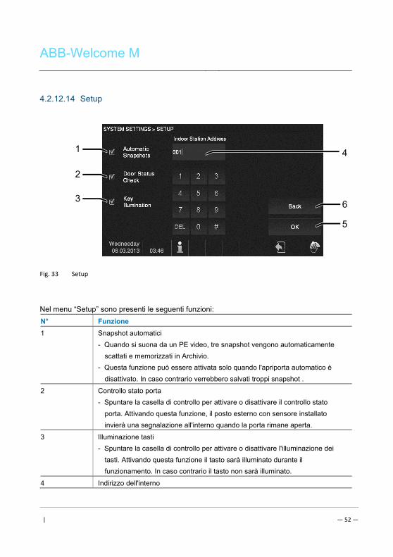
ABB-Welcome M
| — 52 —
4.2.12.14 Setup
Fig. 33 Setup
Nel menu “Setup” sono presenti le seguenti funzioni:
N° Funzione
1 Snapshot automatici
- Quando si suona da un PE video, tre snapshot vengono automaticamente
scattati e memorizzati in Archivio.
- Questa funzione può essere attivata solo quando l'apriporta automatico è
disattivato. In caso contrario verrebbero salvati troppi snapshot .
2 Controllo stato porta
- Spuntare la casella di controllo per attivare o disattivare il controllo stato
porta. Attivando questa funzione, il posto esterno con sensore installato
invierà una segnalazione all'interno quando la porta rimane aperta.
3 Illuminazione tasti
- Spuntare la casella di controllo per attivare o disattivare l'illuminazione dei
tasti. Attivando questa funzione il tasto sarà illuminato durante il
funzionamento. In caso contrario il tasto non sarà illuminato.
4 Indirizzo dell'interno
6
5
1
2
3
4
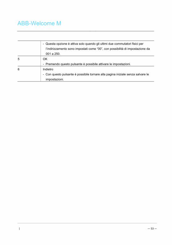
ABB-Welcome M
| — 53 —
- Questa opzione è attiva solo quando gli ultimi due commutatori fisici per
l’indirizzamento sono impostati come “00”, con possibilità di impostazione da
001 a 250.
5 OK
- Premendo questo pulsante è possibile attivare le impostazioni.
6 Indietro
- Con questo pulsante è possibile tornare alla pagina iniziale senza salvare le
impostazioni.
ABB-Welcome M
| — 54 —
4.2.12.15 Aggiornamento Firmware Se il firmware del dispositivo necessita di essere aggiornato, procedere come segue:
1. Richiedere la nuova versione firmware all'installatore elettrico e copiarla sulla scheda SD.
2. Inserire la scheda SD nello slot dell'interno.
3. Selezionare “Aggiornamento Firmware”
4. Eseguire l'aggiornamento firmware selezionando “Aggiorna”
5. Confermare il popup con “sì”. Pos: 67 /DinA4 - Anleitungen Online/Ueberschriften/2./Reinigung @ 19\mod_1310733980533_15.docx @ 107853 @ 2 @ 1
ABB-Welcome M
| — 55 —
4.3 Pulizia Pos: 68 /DinA4 - Anleitungen Online/Inhalt/KNX/DoorEntry/Reinigung/Reinigung Touchscreenmonitor @ 19\mod_1310734108978_15.docx @ 107862 @ @ 1
Attenzione
Rischio di danneggiamento della superficie dello schermo.
Oggetti duri o appuntiti possono danneggiare la superficie dello schermo.
Non servirsi di oggetti simili per l'utilizzo del touch screen.
- Usare le dita o uno stilo di plastica.
Prodotti per la pulizia e agenti abrasivi possono danneggiare la superficie
dello schermo.
- Pulire le superfici con un panno morbido e un detergente vetri in
commercio.
- Non utilizzare prodotti di pulizia abrasivi.
Pos: 69 /Busch-Jaeger (Neustruktur)/Modul-Struktur/Online-Dokumentation/Steuermodule - Online-Dokumentation (--> Für alle Dokumente <--)/++++++++++++ Seitenumbruch ++++++++++++ @ 9\mod_1268898668093_0.docx @ 52149 @ @ 1
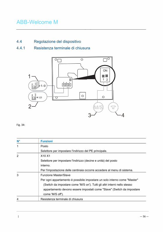
ABB-Welcome M
| — 56 —
Pos: 70 /DinA4 - Anleitungen Online/Ueberschriften/2./Geraeteeinstellungen @ 18\mod_1302768847744_15.docx @ 103548 @ 2 @ 1
4.4 Regolazione del dispositivo Pos: 71 /DinA4 - Anleitungen Online/Ueberschriften/3./Abschlusswiderstand @ 19\mod_1321958079906_15.docx @ 110083 @ 3 @ 1 Pos: 72 /DinA4 - Anleitungen Online/Inhalt/KNX/DoorEntry/Bedienung/Abschlusswiderstand setzen 83220-AP-xxx @ 19\mod_1310723392369_15.docx @ 107841 @ @ 1
4.4.1 Resistenza terminale di chiusura
Fig. 34:
Pos: 74 /DinA4 - Anleitungen Online/Inhalt/KNX/DoorEntry/Bedienung/Master/Slave Schalter setzen 83220-AP-xxx @ 19\mod_1310723320966_15.docx @ 107833 @ @
N° Funzioni
1 Posto
Selettore per impostare l'indirizzo del PE principale.
2 X10 X1
Selettore per impostare l'indirizzo (decine e unità) del posto
interno.
Per l'impostazione delle centinaia occorre accedere al menu di sistema.
3 Funzione Master/Slave
Per ogni appartamento è possibile impostare un solo interno come "Master"
(Switch da impostare come 'M/S on'). Tutti gli altri interni nello stesso
appartamento devono essere impostati come "Slave" (Switch da impostare
come 'M/S off').
4 Resistenza terminale di chiusura
ABB-Welcome M
| — 57 —
Negli impianti video o impianti misti audio/video, lo switch deve essere
impostato come 'RC on' sull'ultimo dispositivo di linea.
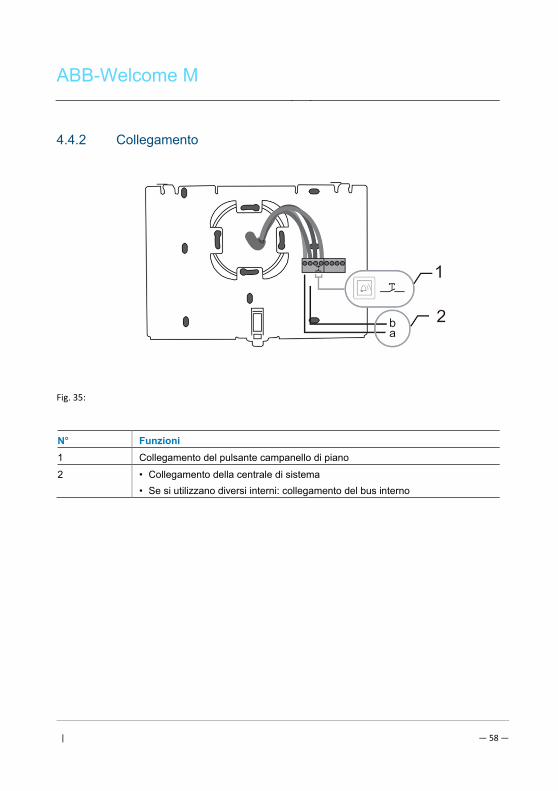
ABB-Welcome M
| — 58 —
4.4.2 Collegamento
Fig. 35:
N° Funzioni
1 Collegamento del pulsante campanello di piano
2 • Collegamento della centrale di sistema
• Se si utilizzano diversi interni: collegamento del bus interno
Pos: 75 /Busch-Jaeger (Neustruktur)/Modul-Struktur/Online-Dokumentation/Steuermodule - Online-Dokumentation (--> Für alle Dokumente <--)/++++++++++++ Seitenumbruch ++++++++++++ @ 9\mod_1268898668093_0.docx @ 52149 @ @ 1
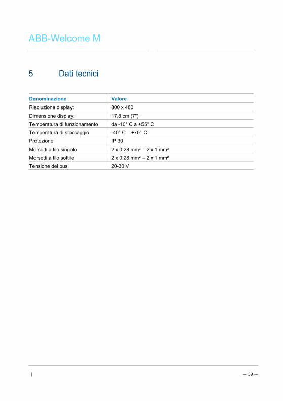
ABB-Welcome M
| — 59 —
Pos: 76 /DinA4 - Anleitungen Online/Ueberschriften/1./Technische Daten @ 18\mod_1302615863001_15.docx @ 103416 @ 1 @ 1
5 Dati tecnici Pos: 77 /DinA4 - Anleitungen Online/Inhalt/KNX/DoorEntry/83220-AP-xxx/Technische Daten - 83220-AP-xxx @ 18\mod_1303212854559_15.docx @ 103705 @ @ 1
Denominazione Valore
Risoluzione display: 800 x 480
Dimensione display: 17,8 cm (7")
Temperatura di funzionamento da -10° C a +55° C
Temperatura di stoccaggio -40° C – +70° C
Protezione IP 30
Morsetti a filo singolo 2 x 0,28 mm² – 2 x 1 mm²
Morsetti a filo sottile 2 x 0,28 mm² – 2 x 1 mm²
Tensione del bus 20-30 V
Pos: 78 /Busch-Jaeger (Neustruktur)/Modul-Struktur/Online-Dokumentation/Steuermodule - Online-Dokumentation (--> Für alle Dokumente <--)/++++++++++++ Seitenumbruch ++++++++++++ @ 9\mod_1268898668093_0.docx @ 52149 @ @ 1
ABB-Welcome M
| — 60 —
Pos: 79 /Busch-Jaeger (Neustruktur)/Modul-Struktur/Online-Dokumentation/Überschriften (--> Für alle Dokumente <--)/1. Ebene/M - O/Montage / Installation @ 18\mod_1302613966111_15.docx @ 103373 @ 1 @ 1
6 Montaggio/Installazione Pos: 80 /Busch-Jaeger (Neustruktur)/Modul-Struktur/Online-Dokumentation/Sicherheit (--> Für alle Dokumente <--)/Warnhinweise/Sicherheit - Niederspannungs- und 230 V-Leitungen @ 18\mod_1302617821491_15.docx @ 103465 @ @ 1
Attenzione
Tensione elettrica!
Rischio di morte ed incendio dovuto alla presenza di tensione elettrica 100-
240 V.
– Non installare contemporaneamente i cavi di bassa tensione e i cavi
100-240 V in una presa da incasso!
Pericolo di carico da 100-240 V sulla linea a bassa tensione in caso di
cortocircuito.
Pos: 81 /Busch-Jaeger (Neustruktur)/Modul-Struktur/Online-Dokumentation/Sicherheit (--> Für alle Dokumente <--)/Warnhinweise/Sicherheit - Fachkenntnisse @ 18\mod_1302774384017_15.docx @ 103564 @ 2 @ 1
6.1 Obblighi dell'elettricista
Attenzione
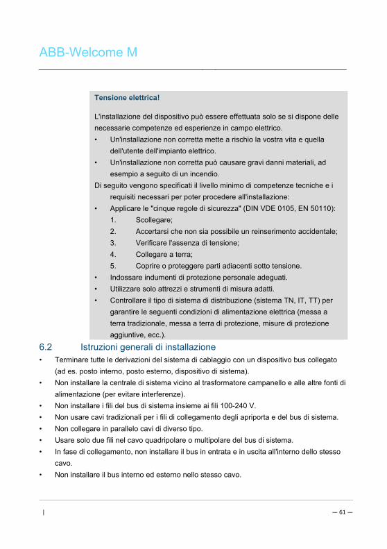
ABB-Welcome M
| — 61 —
Tensione elettrica!
L'installazione del dispositivo può essere effettuata solo se si dispone delle
necessarie competenze ed esperienze in campo elettrico.
• Un'installazione non corretta mette a rischio la vostra vita e quella
dell'utente dell'impianto elettrico.
• Un'installazione non corretta può causare gravi danni materiali, ad
esempio a seguito di un incendio.
Di seguito vengono specificati il livello minimo di competenze tecniche e i
requisiti necessari per poter procedere all'installazione:
• Applicare le "cinque regole di sicurezza" (DIN VDE 0105, EN 50110):
1. Scollegare;
2. Accertarsi che non sia possibile un reinserimento accidentale;
3. Verificare l'assenza di tensione;
4. Collegare a terra;
5. Coprire o proteggere parti adiacenti sotto tensione.
• Indossare indumenti di protezione personale adeguati.
• Utilizzare solo attrezzi e strumenti di misura adatti.
• Controllare il tipo di sistema di distribuzione (sistema TN, IT, TT) per
garantire le seguenti condizioni di alimentazione elettrica (messa a
terra tradizionale, messa a terra di protezione, misure di protezione
aggiuntive, ecc.). Pos: 82 /DinA4 - Anleitungen Online/Inhalt/KNX/DoorEntry/Montage/Montagehinweise - Allgemein @ 19\mod_1310563670478_15.docx @ 107743 @ 2 @ 1
6.2 Istruzioni generali di installazione
• Terminare tutte le derivazioni del sistema di cablaggio con un dispositivo bus collegato
(ad es. posto interno, posto esterno, dispositivo di sistema).
• Non installare la centrale di sistema vicino al trasformatore campanello e alle altre fonti di
alimentazione (per evitare interferenze).
• Non installare i fili del bus di sistema insieme ai fili 100-240 V.
• Non usare cavi tradizionali per i fili di collegamento degli apriporta e del bus di sistema.
• Non collegare in parallelo cavi di diverso tipo.
• Usare solo due fili nel cavo quadripolare o multipolare del bus di sistema.
• In fase di collegamento, non installare il bus in entrata e in uscita all'interno dello stesso
cavo.
• Non installare il bus interno ed esterno nello stesso cavo. Pos: 83 /Busch-Jaeger (Neustruktur)/Modul-Struktur/Online-Dokumentation/Steuermodule - Online-Dokumentation (--> Für alle Dokumente <--)/++++++++++++ Seitenumbruch ++++++++++++ @ 9\mod_1268898668093_0.docx @ 52149 @ @ 1
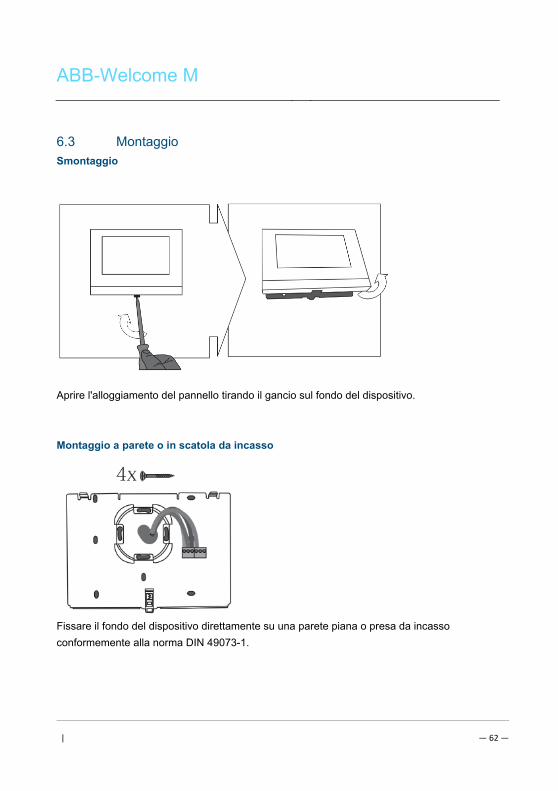
ABB-Welcome M
| — 62 —
Pos: 84 /Busch-Jaeger (Neustruktur)/Modul-Struktur/Online-Dokumentation/Überschriften (--> Für alle Dokumente <--)/2. Ebene/M - O/Montage @ 18\mod_1302615960458_15.docx @ 103424 @ 2 @ 1
6.3 Montaggio Pos: 85.1 /DinA4 - Anleitungen Online/Inhalt/KNX/DoorEntry/83220-AP-xxx/Montage - Module/Montage - Montagedose -- 83220-AP-xxx @ 19\mod_1323250406848_15.docx @ 111098 @ @ 1
Smontaggio
Aprire l'alloggiamento del pannello tirando il gancio sul fondo del dispositivo.
Montaggio a parete o in scatola da incasso
Fissare il fondo del dispositivo direttamente su una parete piana o presa da incasso
conformemente alla norma DIN 49073-1.
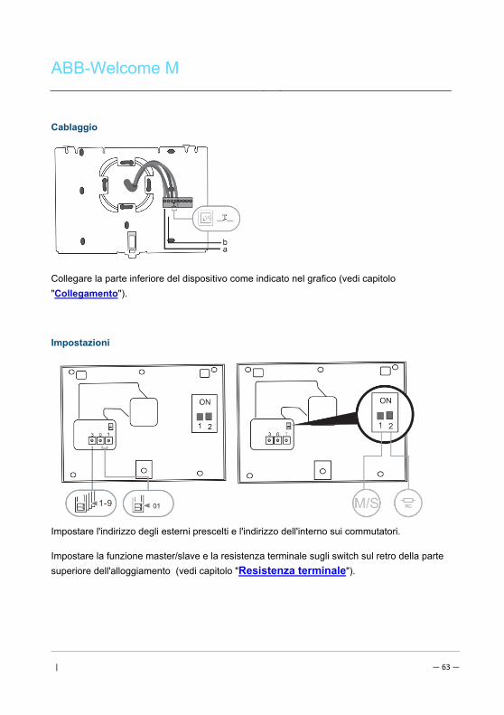
ABB-Welcome M
| — 63 —
Cablaggio
Collegare la parte inferiore del dispositivo come indicato nel grafico (vedi capitolo
"Collegamento").
Impostazioni
Impostare l'indirizzo degli esterni prescelti e l'indirizzo dell'interno sui commutatori.
Impostare la funzione master/slave e la resistenza terminale sugli switch sul retro della parte
superiore dell'alloggiamento (vedi capitolo "Resistenza terminale").
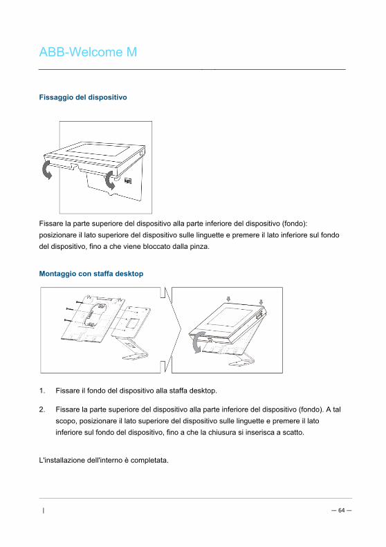
ABB-Welcome M
| — 64 —
Fissaggio del dispositivo
Fissare la parte superiore del dispositivo alla parte inferiore del dispositivo (fondo):
posizionare il lato superiore del dispositivo sulle linguette e premere il lato inferiore sul fondo
del dispositivo, fino a che viene bloccato dalla pinza.
Montaggio con staffa desktop
1. Fissare il fondo del dispositivo alla staffa desktop.
2. Fissare la parte superiore del dispositivo alla parte inferiore del dispositivo (fondo). A tal
scopo, posizionare il lato superiore del dispositivo sulle linguette e premere il lato
inferiore sul fondo del dispositivo, fino a che la chiusura si inserisca a scatto.
L'installazione dell'interno è completata.
ABB-Welcome M
| — 65 —
Pos: 94 /Busch-Jaeger (Neustruktur)/Modul-Struktur/Online-Dokumentation/Steuermodule - Online-Dokumentation (--> Für alle Dokumente <--)/++++++++++++ Seitenumbruch ++++++++++++ @ 9\mod_1268898668093_0.docx @ 52149 @ @ 1

ABB-Welcome M
Pos: 95 /DinA4 - Anleitungen Online/Inhalt/KNX/DoorEntry/Projektierung-Merkblatt/ProjektierPos: 97 /Busch-Jaeger (Neustruktur)/Modul-Struktur/Online-Dokumentation/Rückseiten (--> Für alle Dokumente <--)/Rückseite - Busch-Jaeger - Allgemein @ 20\mod_1327320074886_15.docx @ 137103 @ @ 1
Avvertenza === Ende der Liste für Textmarke Backcover ===
Ci riserviamo il diritto di apportare, in qualsiasi momento, modifiche tecniche o modificare il
contenuto del presente documento senza preavviso.
Le specifiche dettagliate concordate al momento dell'ordine si applicano a tutti gli ordini. ABB
declina ogni responsabilità per eventuali errori o incompletezze in questo documento.
Ci riserviamo tutti i diritti del presente documento, degli argomenti e delle illustrazioni ivi
contenute. È vietata la riproduzione, la divulgazione a terzi o l'utilizzo dei relativi contenuti in
toto o in parte, senza il previo consenso scritto da parte di ABB.
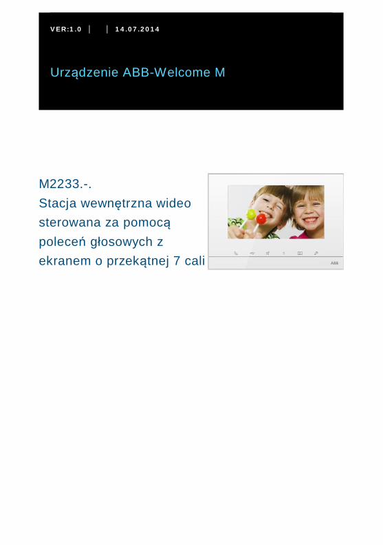
VER:1.0 │ │ 14.07.2014
Urządzenie ABB-Welcome M
Pos: 2 /DinA4 - Anl eitun gen Online /Inh alt/KNX/Doo rEntry /832 20-AP- xxx/Tit elblat t - 832 20-AP-xxx - ABB @ 1 9\m od_ 132 3249 806 476 _15. docx @ 11 108 4 @ @ 1
M2233.-.Stacja wewnętrzna wideosterowana za pomocąpoleceń głosowych zekranem o przekątnej 7 cali
=== E nde der Liste für Tex tma rke C over == =
ABB-Welcome
| — 2 —
Pos: 4 /Busc h-Ja ege r (N eust rukt ur)/ Mo dul-St ruktu r/Onli ne-D oku ment ation /Inh altsve rzeich nis ( --> Fü r alle Doku men te <-- )/In haltsve rzeic hnis @ 19\ mod _13 206 490 4438 6_1 5.d ocx @ 109 653 @ @ 1
1 Bezpieczeństwo ........................................................................................ 42 Przeznaczenie .......................................................................................... 43 Środowisko ............................................................................................... 4
3.1 Urządzenia ABB ........................................................................ 44 Działanie ................................................................................................... 6
4.1 Operacje standardowe .............................................................. 64.1.1 Elementy sterujące .................................................................... 64.1.2 Ekran powitalny i pasek stanu.................................................... 84.2 Elementy sterujące .................................................................. 114.2.1 Nadzór .................................................................................... 114.2.2 Interkom ................................................................................. 124.2.3 Połączenie z konsolą portierską ............................................... 134.2.4 Siłownik przełącznika .............................................................. 144.2.5 Ustawianie połączeń głosowego i wideo................................... 154.2.6 Otwieranie drzwi ..................................................................... 164.2.7 Wyciszenie ............................................................................. 174.2.8 Włączanie funkcji niestandardowych ........................................ 184.2.9 Pamięć zdarzeń i zdjęć / historia .............................................. 204.2.10 Informacje ............................................................................... 244.2.11 Wkładanie karty SD ................................................................. 254.2.12 Ustawienia .............................................................................. 264.2.12.1 Przegląd ................................................................................. 264.2.12.2 Interkom ................................................................................. 294.2.12.3 Siłownik przełącznika .............................................................. 324.2.12.4 Przycisk programowalny .......................................................... 344.2.12.5 Zarządzanie domem pod nieobecność mieszkańców ............... 354.2.12.6 Wiadomość głosowa ............................................................... 374.2.12.7 Ustawianie hasła otwierania drzwi ........................................... 404.2.12.8 Lista zastrzeżeń ...................................................................... 414.2.12.9 Ustawienia audio ..................................................................... 424.2.12.10 Automatyczne zwalnianie blokady ........................................... 444.2.12.11 Ustawienia wyświetlacza ......................................................... 464.2.12.12 Data i godzina ......................................................................... 484.2.12.13 Język ...................................................................................... 504.2.12.14 Konfiguracja ............................................................................ 514.2.12.15 Aktualizacja oprogramowania układowego ............................... 534.3 Czyszczenie............................................................................ 544.4 Regulacja urządzenia .............................................................. 554.4.1 Rezystor końcowy ................................................................... 55
ABB-Welcome
| — 3 —
4.4.2 Połączenie .............................................................................. 565 Dane techniczne ..................................................................................... 576 Montaż / instalacja .................................................................................. 58
6.1 Wymagania wobec elektryków ................................................. 586.2 Ogólna instrukcja montażu ...................................................... 596.3 Montaż ................................................................................... 60
=== E nde der Liste für Tex tma rke TOC == =
ABB-Welcome
| — 4 —
Pos: 6 /Busc h-Ja ege r (N eust rukt ur)/ Mo dul-St ruktu r/Onli ne-D oku ment ation /Übe rschri ften (- -> Für alle D okum ent e < --)/ 1. Eb ene/S - T /Sicher heit @ 18\ mod _13 026 127 917 90_ 15.d ocx @ 103 357 @ 1 @ 1
1 BezpieczeństwoPos: 7 /Busc h-Ja ege r (N eust rukt ur)/ Mo dul-St ruktu r/Onli ne-D oku ment ation /Sicher heit (-- > Für alle Dok um ente <- -)/Wa rn hinweise /Sicher heit - 23 0 V @ 18\m od_ 130 260 681 675 0_15 .docx @ 1 033 08 @ @ 1
OstrzeżenieNapięcie elektryczne!Ryzyko śmierci i pożaru z powodu napięcia elektrycznego równego 100–240 V.– Prace przy układzie zasilania o mocy 100–240 V mogą być
wykonywane tylko przez uprawnionych elektryków!– Odłączyć zasilanie elektryczne przed instalacją lub demontażem!
Pos: 8 /Busc h-Ja ege r (N eust rukt ur)/ Mo dul-St ruktu r/Onli ne-D oku ment ation /Übe rschri ften (- -> Für alle D okum ent e < --)/ 1. Eb ene/A - F /Bestim mun gsge mä ßer Geb rau ch @ 18\ mod _13 027 6332 131 6_1 5.do cx @ 1034 83 @ 1 @ 1
2 PrzeznaczeniePos: 9 /DinA4 - Anl eitun gen Online /Inh alt/KNX/Doo rEntry /832 20-AP- xxx/Besti mmu ngsg em aesse r Ge bra uch - 83 220 -AP-xxx- 500 @ 2 0\mo d_1 324 561 168 699 _15. docx @ 11 272 8 @ @ 1
Urządzenie M2233x-x stanowi integralną część systemu domofonowego ABB WelcomeM, działającą wyłącznie z elementami tego systemu. Urządzenie można instalować tylkow suchych pomieszczeniach wewnątrz budynku.
Pos: 10 /B usch-J aeg er (Neus truk tur )/M odul -Strukt ur/O nline -Doku me ntatio n/Übe rsch rifte n ( --> Fü r alle Doku men te < -- )/1. E bene /U - Z/U mwelt @ 18\ mod _13 026 141 5896 7_1 5.d ocx @ 103 383 @ 1 @ 1
3 ŚrodowiskoPos: 11 /B usch-J aeg er (Neus truk tur )/M odul -Strukt ur/O nline -Doku me ntatio n/Umw elt ( --> Für all e Doku me nte <-- )/Hinweis e/Hinw eis - U mwelt - Hinweis Elektr oge räte @ 1 8\mo d_1 302 763 973 434 _15. docx @ 10 350 0 @ @ 1
Ochrona środowiska!Nie można wyrzucać urządzeń elektrycznych ani elektronicznych zodpadami z gospodarstwa domowego.– Urządzenie zawiera cenne surowce, które można ponownie
wykorzystać. Dlatego należy je oddać do odpowiedniego punktuzbiórki.
Pos: 12 /Di nA4 - A nleitu ngen Onlin e/Ueb ersc hrift en/2 ./ABB Gera ete @ 19 \mo d_1 323 162 843 832_ 15. docx @ 11 087 5 @ 2 @ 1
3.1 Urządzenia ABBPos: 13 /B usch-J aeg er (Neus truk tur )/M odul -Strukt ur/O nline -Doku me ntatio n/Umw elt ( --> Für all e Doku me nte <-- )/Hinweis e/Hinw eis - U mwelt - ABB Elektro ger äte @ 19\ mo d_1 3231 627 458 39_ 15.d ocx @ 110 867 @ @ 1
Na wszystkich materiałach pakunkowych i urządzeniach firmy ABB znajdują sięoznakowania i symbole atestujące dotyczące ich właściwej utylizacji. Materiałypakunkowe i urządzenia elektryczne, jak również ich elementy należy zawsze oddawaćdo utylizacji w autoryzowanych punktach zbiórki lub zakładach utylizacji odpadów.
ABB-Welcome
| — 5 —
Produkty firmy ABB spełniają wymogi prawne i są w szczególności zgodne z ustawami ourządzeniach elektrycznych i elektronicznych oraz rozporządzeniem REACH.(Dyrektywa UE 2002/96/EG WEEE i RoHS 2002/95/WE)(Rozporządzenie UE REACH i ustawa wykonawcza do rozporządzenia (WE) nr1907/2006)
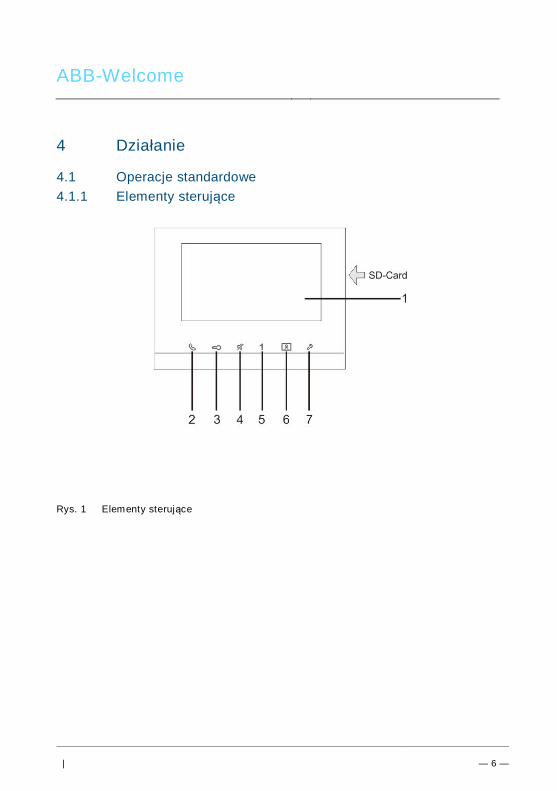
ABB-Welcome
| — 6 —
Pos: 18 /Di nA4 - A nleitu ngen Onlin e/Ueb ersc hrift en/1 ./Bedie nun g @ 18\m od_ 130 261 392 416 5_15 .docx @ 1 033 65 @ 1 @ 1
4 DziałaniePos: 19 /Di nA4 - A nleitu ngen Onlin e/Ueb ersc hrift en/2 ./Nor male r Bet rieb @ 18 \mo d_1 302 768 8209 65_ 15. docx @ 10 3540 @ 2 @ 1
4.1 Operacje standardowePos: 20 /Di nA4 - A nleitu ngen Onlin e/Ueb ersc hrift en/3 ./Bedie nele men te @ 20\ mod _13 232 6022 055 9_1 5.do cx @ 1 116 47 @ 3 @ 1
4.1.1 Elementy sterującePos: 21 /Di nA4 - A nleitu ngen Onlin e/In halt/KNX/Do orEnt ry/83 220 -AP-xxx/Be dienel eme nte - 8 322 0-AP-xxx @ 18\ mo d_1 3032 128 536 05_ 15.d ocx @ 103 673 @ @ 1
Rys. 1 Elementy sterujące
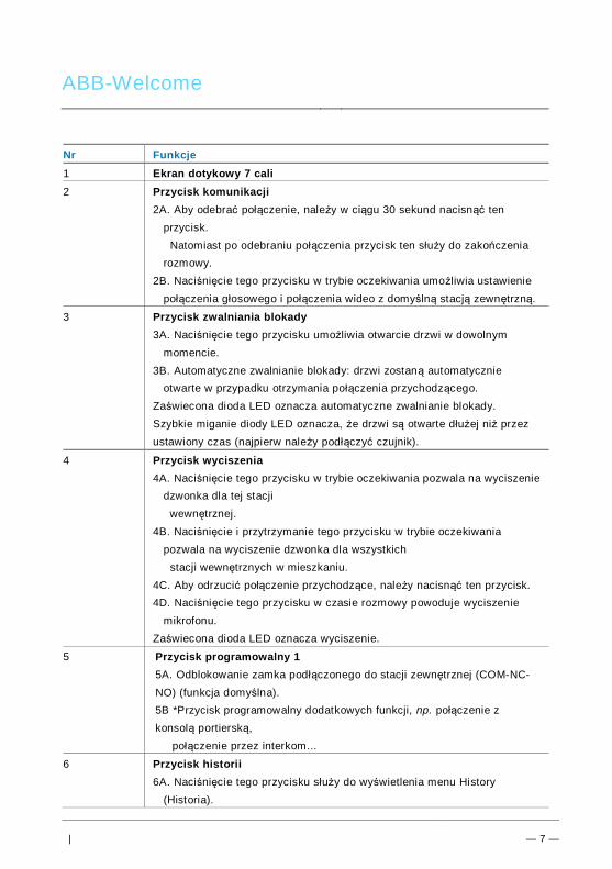
ABB-Welcome
| — 7 —
Nr Funkcje1 Ekran dotykowy 7 cali2 Przycisk komunikacji
2A. Aby odebrać połączenie, należy w ciągu 30 sekund nacisnąć tenprzycisk.
Natomiast po odebraniu połączenia przycisk ten służy do zakończeniarozmowy.
2B. Naciśnięcie tego przycisku w trybie oczekiwania umożliwia ustawieniepołączenia głosowego i połączenia wideo z domyślną stacją zewnętrzną.
3 Przycisk zwalniania blokady3A. Naciśnięcie tego przycisku umożliwia otwarcie drzwi w dowolnym
momencie.3B. Automatyczne zwalnianie blokady: drzwi zostaną automatycznie
otwarte w przypadku otrzymania połączenia przychodzącego.Zaświecona dioda LED oznacza automatyczne zwalnianie blokady.Szybkie miganie diody LED oznacza, że drzwi są otwarte dłużej niż przezustawiony czas (najpierw należy podłączyć czujnik).
4 Przycisk wyciszenia4A. Naciśnięcie tego przycisku w trybie oczekiwania pozwala na wyciszenie
dzwonka dla tej stacji wewnętrznej.4B. Naciśnięcie i przytrzymanie tego przycisku w trybie oczekiwania
pozwala na wyciszenie dzwonka dla wszystkich stacji wewnętrznych w mieszkaniu.4C. Aby odrzucić połączenie przychodzące, należy nacisnąć ten przycisk.4D. Naciśnięcie tego przycisku w czasie rozmowy powoduje wyciszenie
mikrofonu.Zaświecona dioda LED oznacza wyciszenie.
5 Przycisk programowalny 15A. Odblokowanie zamka podłączonego do stacji zewnętrznej (COM-NC-NO) (funkcja domyślna).5B *Przycisk programowalny dodatkowych funkcji, np. połączenie zkonsolą portierską,
połączenie przez interkom...
6 Przycisk historii6A. Naciśnięcie tego przycisku służy do wyświetlenia menu History
(Historia).
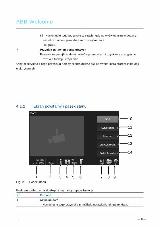
ABB-Welcome
| — 8 —
6B. Naciśnięcie tego przycisku w czasie, gdy na wyświetlaczu widocznyjest obraz wideo, powoduje ręczne wykonanie migawki.
7 Przycisk ustawień systemowychPozwala na przejście do ustawień systemowych i uzyskanie dostępu do
różnych funkcji urządzenia.
*Aby skorzystać z tego przycisku należy skontaktować się ze swoim instalatorem instalacjielektrycznych.
4.1.2 Ekran powitalny i pasek stanu
Fig. 2 Pasek stanu
Podczas połączenia dostępne są następujące funkcje:Nr Funkcje1 Aktualna data
– Naciśnięcie tego przycisku umożliwia ustawienie aktualnej daty.
3 92 4 65 7 8
10
1
11
12
13
14
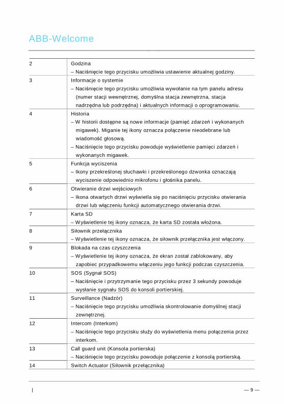
ABB-Welcome
| — 9 —
2 Godzina– Naciśnięcie tego przycisku umożliwia ustawienie aktualnej godziny.
3 Informacje o systemie– Naciśnięcie tego przycisku umożliwia wywołanie na tym panelu adresu
(numer stacji wewnętrznej, domyślna stacja zewnętrzna, stacjanadrzędna lub podrzędna) i aktualnych informacji o oprogramowaniu.
4 Historia– W historii dostępne są nowe informacje (pamięć zdarzeń i wykonanych
migawek). Miganie tej ikony oznacza połączenie nieodebrane lubwiadomość głosową.
– Naciśnięcie tego przycisku powoduje wyświetlenie pamięci zdarzeń iwykonanych migawek.
5 Funkcja wyciszenia– Ikony przekreślonej słuchawki i przekreślonego dzwonka oznaczają
wyciszenie odpowiednio mikrofonu i głośnika panelu.
6 Otwieranie drzwi wejściowych– Ikona otwartych drzwi wyświetla się po naciśnięciu przycisku otwierania
drzwi lub włączeniu funkcji automatycznego otwierania drzwi.
7 Karta SD– Wyświetlenie tej ikony oznacza, że karta SD została włożona.
8 Siłownik przełącznika– Wyświetlenie tej ikony oznacza, że siłownik przełącznika jest włączony.
9 Blokada na czas czyszczenia– Wyświetlenie tej ikony oznacza, że ekran został zablokowany, aby
zapobiec przypadkowemu w łączeniu jego funkcji podczas czyszczenia.
10 SOS (Sygnał SOS)– Naciśnięcie i przytrzymanie tego przycisku przez 3 sekundy powoduje
wysłanie sygnału SOS do konsoli portierskiej.
11 Surveillance (Nadzór)– Naciśnięcie tego przycisku umożliwia skontrolowanie domyślnej stacji
zewnętrznej.
12 Intercom (Interkom)– Naciśnięcie tego przycisku służy do wyświetlenia menu połączenia przez
interkom.
13 Call guard unit (Konsola portierska)– Naciśnięcie tego przycisku powoduje połączenie z konsolą portierską.
14 Switch Actuator (Siłownik przełącznika)
ABB-Welcome
| — 10 —
– Naciśnięcie tego przycisku służy do wyświetlenia menu siłownikaprzełącznika.
Pos: 29 /B usch-J aeg er (Neus truk tur )/M odul -Strukt ur/O nline -Doku me ntatio n/Steu er mod ule - Onlin e-Dok ume ntati on ( -- > Für alle Dok ume nte <- -)/ +++ ++ ++ +++ ++ S eiten umb ruch + +++ ++ ++ +++ + @ 9\m od_ 126 8898 668 093 _0. docx @ 521 49 @ @ 1
Pos: 22 /B usch-J aeg er (Neus truk tur )/M odul -Strukt ur/O nline -Doku me ntatio n/Steu er mod ule - Onlin e-Dok ume ntati on ( -- > Für alle Dok ume nte <- -)/ +++ ++ ++ +++ ++ S eiten umb ruch + +++ ++ ++ +++ + @ 9\m od_ 126 8898 668 093 _0. docx @ 521 49 @ @ 1
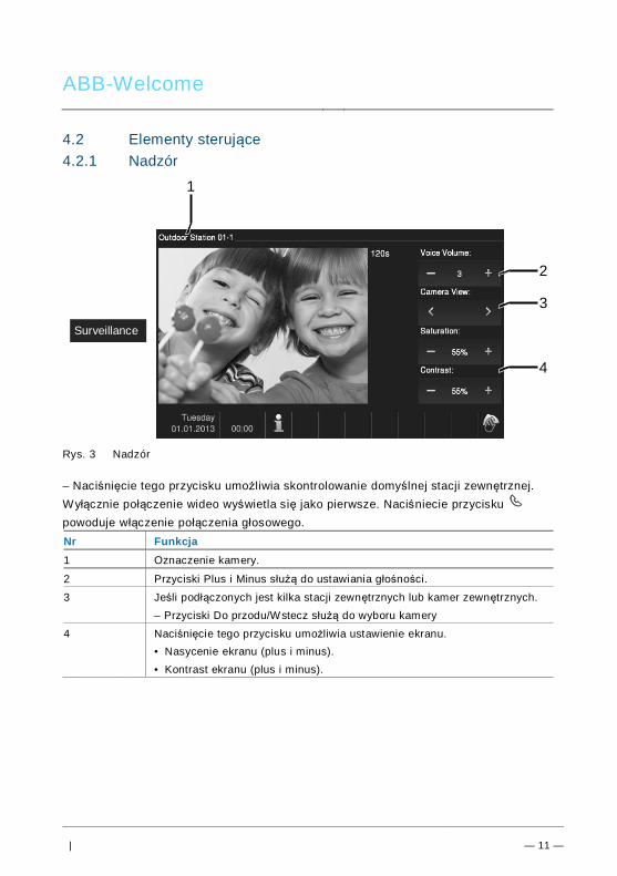
ABB-Welcome
| — 11 —
Pos: 26 /Di nA4 - A nleitu ngen Onlin e/Ueb ersc hrift en/2 ./Bedie nakti onen @ 2 0\m od_ 1323 262 294 281 _15. docx @ 11 191 1 @ 2 @ 1
4.2 Elementy sterującePos: 27 /Di nA4 - A nleitu ngen Onlin e/Ueb ersc hrift en/3 ./Spr ech- und Videov erbi ndu ng @ 20\ mod _13 232 6236 870 0_1 5.do cx @ 1119 27 @ 3 @ 1
4.2.1 NadzórPos: 28 /Di nA4 - A nleitu ngen Onlin e/In halt/KNX/Do orEnt ry/83 220 -AP-xxx/Sp rech - u nd Vide over bind ung - 8 322 0-AP-xxx @ 20\ mo d_1 3232 623 418 52_ 15.d ocx @ 111 919 @ @ 1
Rys. 3 Nadzór
– Naciśnięcie tego przycisku umożliwia skontrolowanie domyślnej stacji zewnętrznej.Wyłącznie połączenie wideo wyświetla się jako pierwsze. Naciśniecie przyciskupowoduje włączenie połączenia głosowego.Nr Funkcja1 Oznaczenie kamery.
2 Przyciski Plus i Minus służą do ustawiania głośności.
3 Jeśli podłączonych jest kilka stacji zewnętrznych lub kamer zewnętrznych.– Przyciski Do przodu/Wstecz służą do wyboru kamery
4 Naciśnięcie tego przycisku umożliwia ustawienie ekranu.• Nasycenie ekranu (plus i minus).• Kontrast ekranu (plus i minus).
Pos: 29 /B usch-J aeg er (Neus truk tur )/M odul -Strukt ur/O nline -Doku me ntatio n/Steu er mod ule - Onlin e-Dok ume ntati on ( -- > Für alle Dok ume nte <- -)/ +++ ++ ++ +++ ++ S eiten umb ruch + +++ ++ ++ +++ + @ 9\m od_ 126 8898 668 093 _0. docx @ 521 49 @ @ 1
2
3
4
1
Surveillance
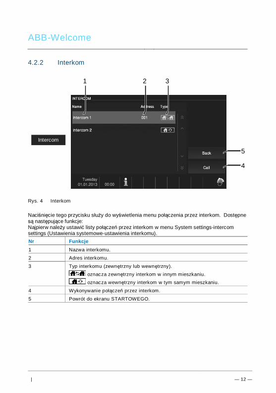
ABB-Welcome
| — 12 —
Pos: 30 /Di nA4 - A nleitu ngen Onlin e/Ueb ersc hrift en/3 ./Tuer oeff nen @ 2 0\mo d_1 323 263 277 453 _15. docx @ 11 193 5 @ 3 @ 1
4.2.2 InterkomPos: 31 /Di nA4 - A nleitu ngen Onlin e/In halt/KNX/Do orEnt ry/83 220 -AP-xxx/ Tue r o effne n - 832 20-AP-x xx @ 20\m od_ 132 326 795 847 9_15 .docx @ 1 121 09 @ @ 1
Rys. 4 Interkom
Naciśnięcie tego przycisku służy do wyświetlenia menu połączenia przez interkom. Dostępnesą następujące funkcje:Najpierw należy ustawić listy połączeń przez interkom w menu System settings-intercomsettings (Ustawienia systemowe-ustawienia interkomu).Nr Funkcje1 Nazwa interkomu.
2 Adres interkomu.
3 Typ interkomu (zewnętrzny lub wewnętrzny). oznacza zewnętrzny interkom w innym mieszkaniu. oznacza wewnętrzny interkom w tym samym mieszkaniu.
4 Wykonywanie połączeń przez interkom.
5 Powrót do ekranu STARTOWEGO.
4
1
Intercom
5
2 3
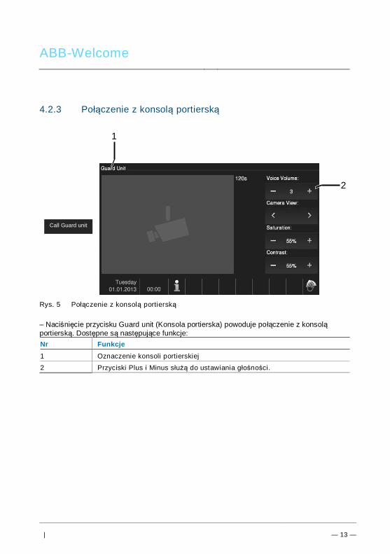
ABB-Welcome
| — 13 —
4.2.3 Połączenie z konsolą portierskąPos: 31 /Di nA4 - A nleitu ngen Onlin e/In halt/KNX/Do orEnt ry/83 220 -AP-xxx/ Tue r o effne n - 832 20-AP-x xx @ 20\m od_ 132 326 795 847 9_15 .docx @ 1 121 09 @ @ 1
Rys. 5 Połączenie z konsolą portierską
– Naciśnięcie przycisku Guard unit (Konsola portierska) powoduje połączenie z konsoląportierską. Dostępne są następujące funkcje:Nr Funkcje1 Oznaczenie konsoli portierskiej
2 Przyciski Plus i Minus służą do ustawiania głośności.
Call Guard unit
2
1
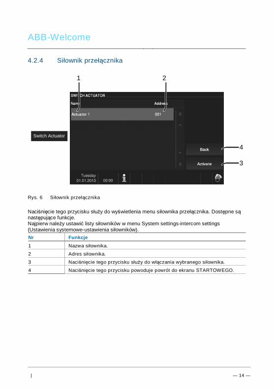
ABB-Welcome
| — 14 —
4.2.4 Siłownik przełącznikaPos: 31 /Di nA4 - A nleitu ngen Onlin e/In halt/KNX/Do orEnt ry/83 220 -AP-xxx/ Tue r o effne n - 832 20-AP-x xx @ 20\m od_ 132 326 795 847 9_15 .docx @ 1 121 09 @ @ 1
Rys. 6 Siłownik przełącznika
Naciśnięcie tego przycisku służy do wyświetlenia menu siłownika przełącznika. Dostępne sąnastępujące funkcje.Najpierw należy ustawić listy siłowników w menu System settings-intercom settings(Ustawienia systemowe-ustawienia siłowników).Nr Funkcje1 Nazwa siłownika.
2 Adres siłownika.
3 Naciśnięcie tego przycisku służy do włączania wybranego siłownika.
4 Naciśnięcie tego przycisku powoduje powrót do ekranu STARTOWEGO.
Switch Actuator
4
1 2
3
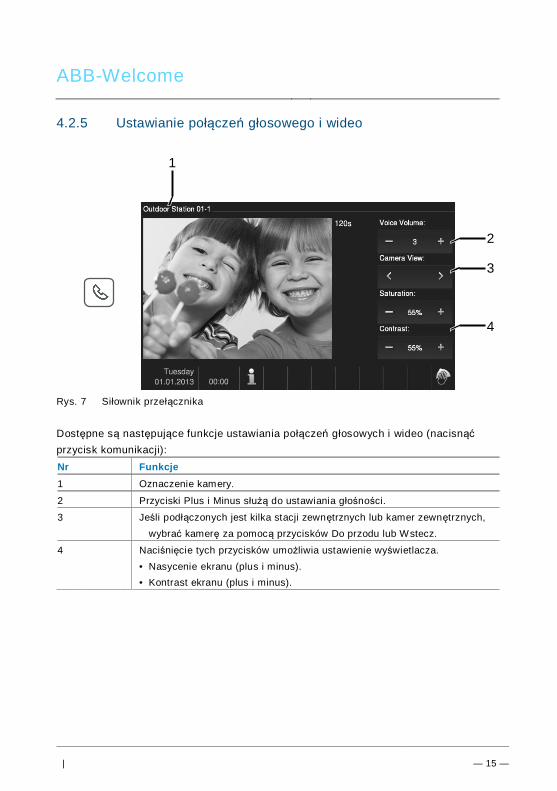
ABB-Welcome
| — 15 —
4.2.5 Ustawianie połączeń głosowego i wideoPos: 31 /Di nA4 - A nleitu ngen Onlin e/In halt/KNX/Do orEnt ry/83 220 -AP-xxx/ Tue r o effne n - 832 20-AP-x xx @ 20\m od_ 132 326 795 847 9_15 .docx @ 1 121 09 @ @ 1
Rys. 7 Siłownik przełącznika
Dostępne są następujące funkcje ustawiania połączeń głosowych i wideo (nacisnąćprzycisk komunikacji):Nr Funkcje1 Oznaczenie kamery.
2 Przyciski Plus i Minus służą do ustawiania głośności.
3 Jeśli podłączonych jest kilka stacji zewnętrznych lub kamer zewnętrznych,wybrać kamerę za pomocą przycisków Do przodu lub Wstecz.
4 Naciśnięcie tych przycisków umożliwia ustawienie wyświetlacza.• Nasycenie ekranu (plus i minus).• Kontrast ekranu (plus i minus).
Pos: 29 /B usch-J aeg er (Neus truk tur )/M odul -Strukt ur/O nline -Doku me ntatio n/Steu er mod ule - Onlin e-Dok ume ntati on ( -- > Für alle Dok ume nte <- -)/ +++ ++ ++ +++ ++ S eiten umb ruch + +++ ++ ++ +++ + @ 9\m od_ 126 8898 668 093 _0. docx @ 521 49 @ @ 1
2
3
4
1
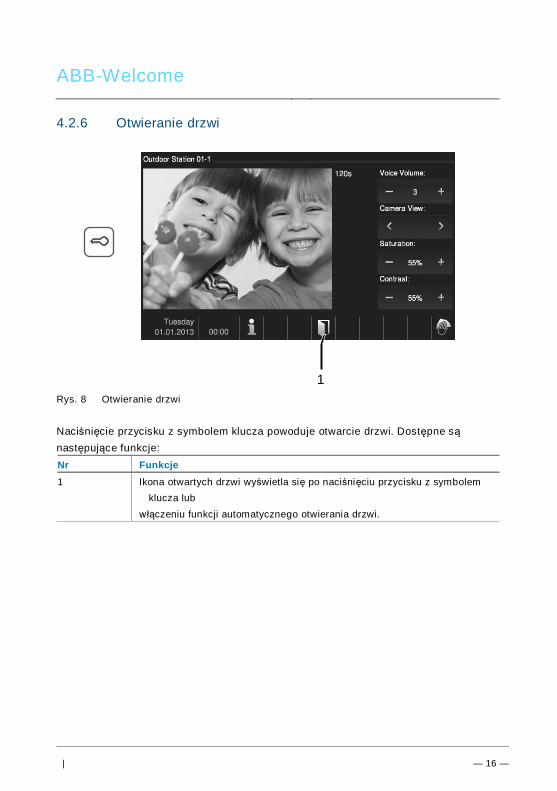
ABB-Welcome
| — 16 —
4.2.6 Otwieranie drzwiPos: 31 /Di nA4 - A nleitu ngen Onlin e/In halt/KNX/Do orEnt ry/83 220 -AP-xxx/ Tue r o effne n - 832 20-AP-x xx @ 20\m od_ 132 326 795 847 9_15 .docx @ 1 121 09 @ @ 1
Rys. 8 Otwieranie drzwi
Naciśnięcie przycisku z symbolem klucza powoduje otwarcie drzwi. Dostępne sąnastępujące funkcje:Nr Funkcje1 Ikona otwartych drzwi wyświetla się po naciśnięciu przycisku z symbolem
klucza lubwłączeniu funkcji automatycznego otwierania drzwi.
1
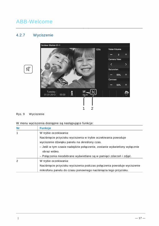
ABB-Welcome
| — 17 —
4.2.7 WyciszeniePos: 31 /Di nA4 - A nleitu ngen Onlin e/In halt/KNX/Do orEnt ry/83 220 -AP-xxx/ Tue r o effne n - 832 20-AP-x xx @ 20\m od_ 132 326 795 847 9_15 .docx @ 1 121 09 @ @ 1
Rys. 9 Wyciszenie
W menu wyciszenia dostępne są następujące funkcje:Nr Funkcje1 W trybie oczekiwania:
Naciśnięcie przycisku wyciszenia w trybie oczekiwania powodujewyciszenie dźwięku panelu na określony czas.– Jeśli w tym czasie nadejdzie połączenie, zostanie wyświetlony wyłącznie
obraz wideo.– Połączenia nieodebrane wyświetlane są w pamięci zdarzeń i zdjęć.
2 W trybie oczekiwania:Naciśnięcie przycisku wyciszenia podczas połączenia powoduje wyciszeniemikrofonu panelu do czasu ponownego naciśnięcia tego przycisku.
1 2
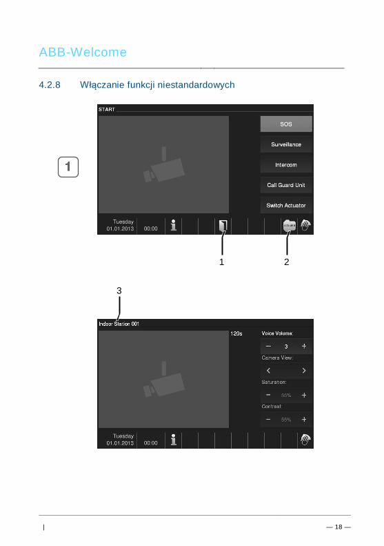
ABB-Welcome
| — 18 —
4.2.8 Włączanie funkcji niestandardowychPos: 31 /Di nA4 - A nleitu ngen Onlin e/In halt/KNX/Do orEnt ry/83 220 -AP-xxx/ Tue r o effne n - 832 20-AP-x xx @ 20\m od_ 132 326 795 847 9_15 .docx @ 1 121 09 @ @ 1
1 2
3
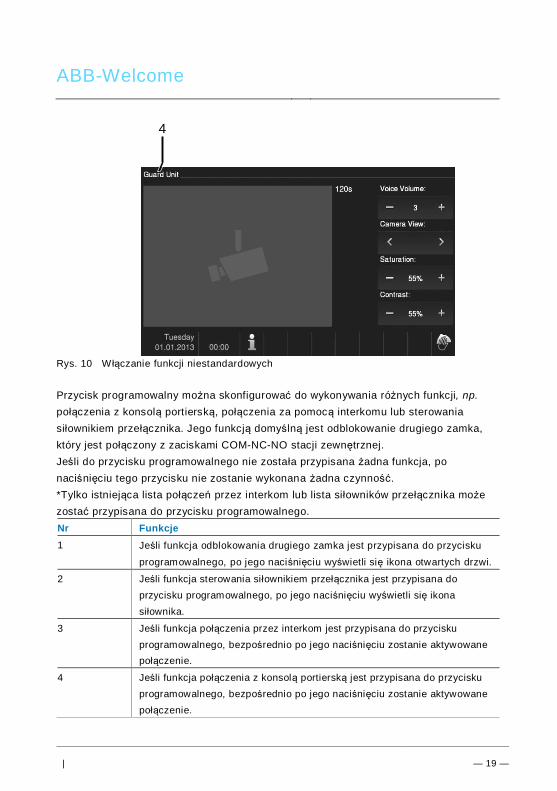
ABB-Welcome
| — 19 —
Rys. 10 W łączanie funkcji niestandardowych
Przycisk programowalny można skonfigurować do wykonywania różnych funkcji, np.połączenia z konsolą portierską, połączenia za pomocą interkomu lub sterowaniasiłownikiem przełącznika. Jego funkcją domyślną jest odblokowanie drugiego zamka,który jest połączony z zaciskami COM-NC-NO stacji zewnętrznej.Jeśli do przycisku programowalnego nie została przypisana żadna funkcja, ponaciśnięciu tego przycisku nie zostanie wykonana żadna czynność.*Tylko istniejąca lista połączeń przez interkom lub lista siłowników przełącznika możezostać przypisana do przycisku programowalnego.Nr Funkcje1 Jeśli funkcja odblokowania drugiego zamka jest przypisana do przycisku
programowalnego, po jego naciśnięciu wyświetli się ikona otwartych drzwi.
2 Jeśli funkcja sterowania siłownikiem przełącznika jest przypisana doprzycisku programowalnego, po jego naciśnięciu wyświetli się ikonasiłownika.
3 Jeśli funkcja połączenia przez interkom jest przypisana do przyciskuprogramowalnego, bezpośrednio po jego naciśnięciu zostanie aktywowanepołączenie.
4 Jeśli funkcja połączenia z konsolą portierską jest przypisana do przyciskuprogramowalnego, bezpośrednio po jego naciśnięciu zostanie aktywowanepołączenie.
4
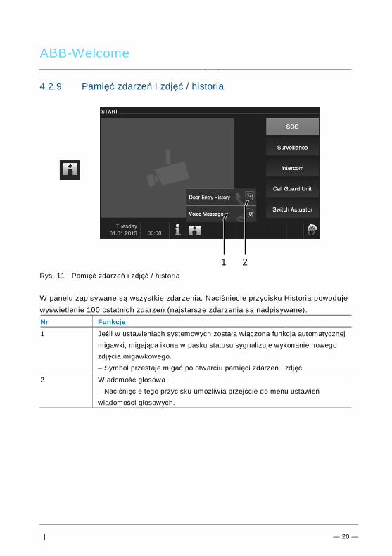
ABB-Welcome
| — 20 —
4.2.9 Pamięć zdarzeń i zdjęć / historiaPos: 31 /Di nA4 - A nleitu ngen Onlin e/In halt/KNX/Do orEnt ry/83 220 -AP-xxx/ Tue r o effne n - 832 20-AP-x xx @ 20\m od_ 132 326 795 847 9_15 .docx @ 1 121 09 @ @ 1
Rys. 11 Pamięć zdarzeń i zdjęć / historia
W panelu zapisywane są wszystkie zdarzenia. Naciśnięcie przycisku Historia powodujewyświetlenie 100 ostatnich zdarzeń (najstarsze zdarzenia są nadpisywane).Nr Funkcje1 Jeśli w ustawieniach systemowych została włączona funkcja automatycznej
migawki, migająca ikona w pasku statusu sygnalizuje wykonanie nowegozdjęcia migawkowego.– Symbol przestaje migać po otwarciu pamięci zdarzeń i zdjęć.
2 Wiadomość głosowa– Naciśnięcie tego przycisku umożliwia przejście do menu ustawieńwiadomości głosowych.
1 2
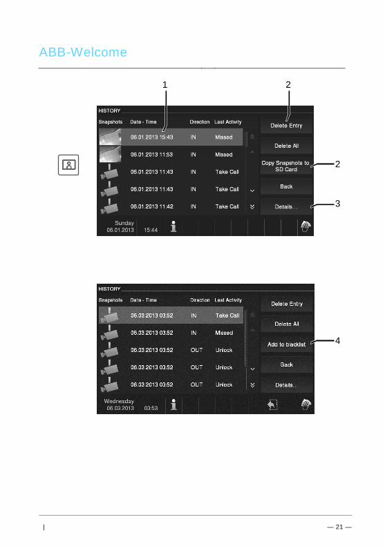
ABB-Welcome
| — 21 —
1 2
2
3
4
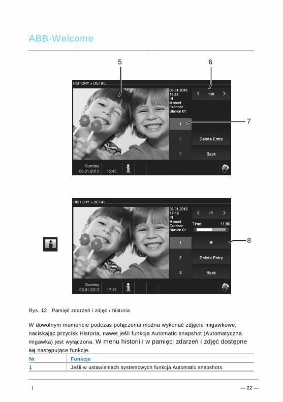
ABB-Welcome
| — 22 —
Rys. 12 Pamięć zdarzeń i zdjęć / historia
W dowolnym momencie podczas połączenia można wykonać zdjęcie migawkowe,naciskając przycisk Historia, nawet jeś li funkcja Automatic snapshot (Automatycznamigawka) jest wyłączona. W menu historii i w pamięci zdarzeń i zdjęć dostępnesą następujące funkcje.Nr Funkcje1 Jeśli w ustawieniach systemowych funkcja Automatic snapshots
8
5 6
7
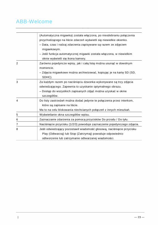
ABB-Welcome
| — 23 —
(Automatyczna migawka) została włączona, po nieodebraniu połączeniaprzychodzącego na liście zdarzeń wyświetli się niewielkie okienko.– Data, czas i rodzaj zdarzenia zapisywane są razem ze zdjęciem
migawkowym.– Jeśli funkcja automatycznej migawki została włączona, w niewielkim
oknie wyświetli się ikona kamery.
2 Zarówno pojedyncze wpisy, jak i całą listę można usunąć w dowolnymmomencie.– Zdjęcia migawkowe można archiwizować, kopiując je na kartę SD (SD,
SDHC).
3 Za każdym razem po naciśnięciu dzwonka wykonywane są trzy zdjęciaodwiedzającego. Zapewnia to uzyskanie optymalnego obrazu.– Dostęp do wszystkich zapisanych zdjęć można uzyskać w oknie
szczegółów.
4 Do listy zastrzeżeń można dodać jedynie te połączenia przez interkom,które są zapisane na liście.
Ma to na celu blokowania niechcianych połączeń z innych mieszkań.
5 Wyświetlanie okna szczegółów wpisu.
6 Zaznaczanie zdarzenia za pomocą przycisków Do przodu / Do tyłu.
7 Naciśnięcie przycisku (1/2/3) powoduje zaznaczenie pojedynczego zdjęcia.
8 Jeśli odwiedzający pozostawił wiadomość głosową, naciśnięcie przyciskuPlay (Odtwarzaj) lub Stop (Zatrzymaj) powoduje odpowiednioodtworzenie lub zatrzymanie odtwarzanej wiadomości.
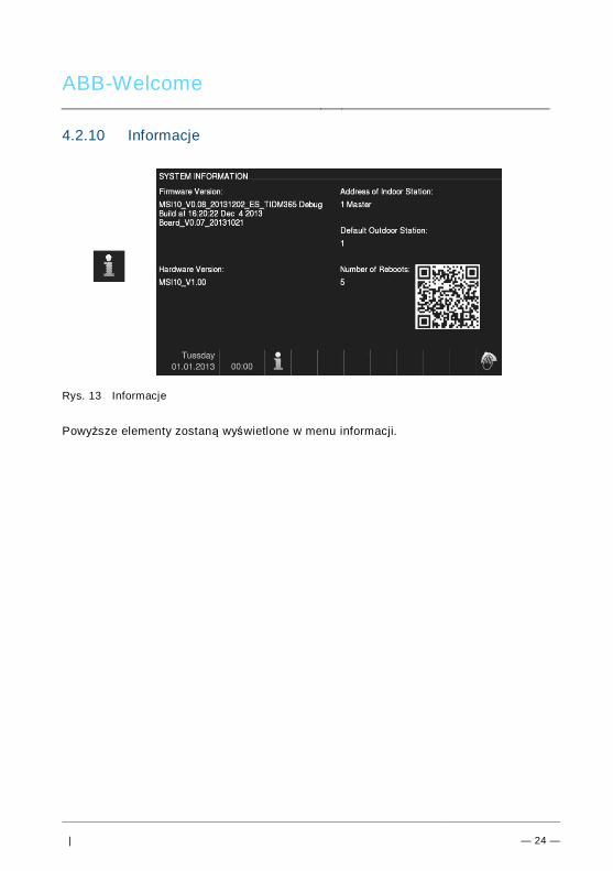
ABB-Welcome
| — 24 —
4.2.10 InformacjePos: 31 /Di nA4 - A nleitu ngen Onlin e/In halt/KNX/Do orEnt ry/83 220 -AP-xxx/ Tue r o effne n - 832 20-AP-x xx @ 20\m od_ 132 326 795 847 9_15 .docx @ 1 121 09 @ @ 1
Rys. 13 Informacje
Powyższe elementy zostaną wyświetlone w menu informacji.
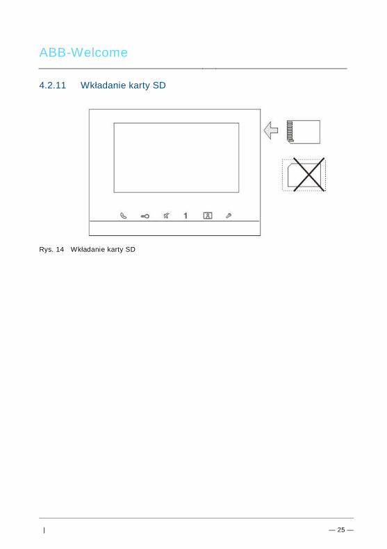
ABB-Welcome
| — 25 —
4.2.11 Wkładanie karty SDPos: 31 /Di nA4 - A nleitu ngen Onlin e/In halt/KNX/Do orEnt ry/83 220 -AP-xxx/ Tue r o effne n - 832 20-AP-x xx @ 20\m od_ 132 326 795 847 9_15 .docx @ 1 121 09 @ @ 1
Rys. 14 Wkładanie karty SD

ABB-Welcome
| — 26 —
4.2.12 UstawieniaPos: 31 /Di nA4 - A nleitu ngen Onlin e/In halt/KNX/Do orEnt ry/83 220 -AP-xxx/ Tue r o effne n - 832 20-AP-x xx @ 20\m od_ 132 326 795 847 9_15 .docx @ 1 121 09 @ @ 1
4.2.12.1 Przegląd
Rys. 15 Przegląd
Naciśnięcie przycisku Settings (Ustawienia) umożliwia dostęp do następujących funkcji:Nr Funkcje1 Intercom (Interkom)
- Ustawianie list interkomów między różnymi mieszkaniami lub w tymsamym mieszkaniu
2 Switch Actuator (Siłownik przełącznika)- W tym menu można ustawić listę siłowników
3 Program Button (Przycisk programowalny)- Ustawianie funkcji dla przycisku programowalnego.
4 Leave Home Management (Zarządzanie domem pod nieobecnośćmieszkańców)
- Ustawianie przekierowania połączeń: ustawianie odbiorcy (np. innastacja wewnętrzna lub konsola portierska), do którego będąprzekierowywane połączenia od odwiedzających podczas nieobecnościmieszkańców.
- Pozostawianie wiadomości: przed wyjściem z domu można nagrać ipozostawić wiadomość dla ewentualnych odwiedzających izarejestrować wiadomości od nich.
5 Voice Message (Wiadomość głosowa)- Tworzenie wiadomości głosowej do członków rodziny lub ustawianie
wiadomości dla ewentualnych odwiedzających informującej o
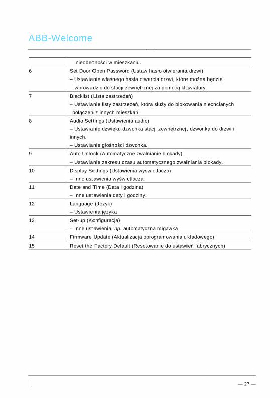
ABB-Welcome
| — 27 —
nieobecności w mieszkaniu.
6 Set Door Open Password (Ustaw hasło otwierania drzwi)– Ustawianie własnego hasła otwarcia drzwi, które można będzie
wprowadzić do stacji zewnętrznej za pomocą klawiatury.
7 Blacklist (Lista zastrzeżeń)– Ustawianie listy zastrzeżeń, która służy do blokowania niechcianychpołączeń z innych mieszkań.
8 Audio Settings (Ustawienia audio)– Ustawianie dźwięku dzwonka stacji zewnętrznej, dzwonka do drzwi iinnych.– Ustawianie głośności dzwonka.
9 Auto Unlock (Automatyczne zwalnianie blokady)– Ustawianie zakresu czasu automatycznego zwalniania blokady.
10 Display Settings (Ustawienia wyświetlacza)– Inne ustawienia wyświetlacza.
11 Date and Time (Data i godzina)– Inne ustawienia daty i godziny.
12 Language (Język)– Ustawienia języka
13 Set-up (Konfiguracja)– Inne ustawienia, np. automatyczna migawka
14 Firmware Update (Aktualizacja oprogramowania układowego)
15 Reset the Factory Default (Resetowanie do ustawień fabrycznych)
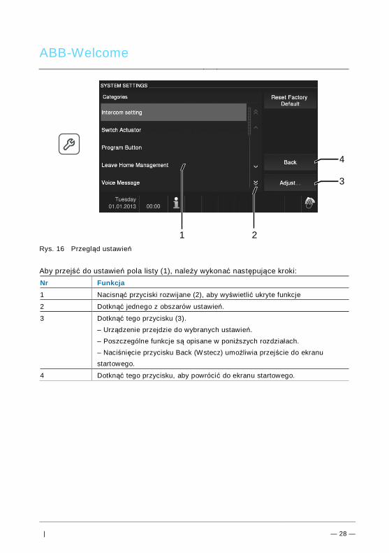
ABB-Welcome
| — 28 —
Rys. 16 Przegląd ustawień
Aby przejść do ustawień pola listy (1), należy wykonać następujące kroki:Nr Funkcja1 Nacisnąć przyciski rozwijane (2), aby wyświetlić ukryte funkcje
2 Dotknąć jednego z obszarów ustawień.
3 Dotknąć tego przycisku (3).– Urządzenie przejdzie do wybranych ustawień.– Poszczególne funkcje są opisane w poniższych rozdziałach.– Naciśnięcie przycisku Back (Wstecz) umożliwia przejście do ekranustartowego.
4 Dotknąć tego przycisku, aby powrócić do ekranu startowego.
4
1 2
3
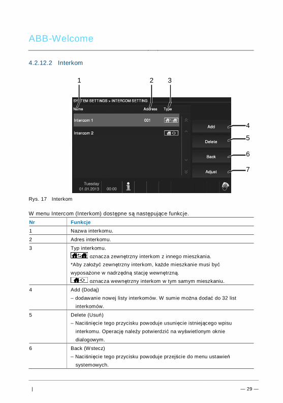
ABB-Welcome
| — 29 —
4.2.12.2 Interkom
Rys. 17 Interkom
W menu Intercom (Interkom) dostępne są następujące funkcje.Nr Funkcje1 Nazwa interkomu.
2 Adres interkomu.
3 Typ interkomu. oznacza zewnętrzny interkom z innego mieszkania.
*Aby założyć zewnętrzny interkom, każde mieszkanie musi byćwyposażone w nadrzędną stację wewnętrzną.
oznacza wewnętrzny interkom w tym samym mieszkaniu.
4 Add (Dodaj)– dodawanie nowej listy interkomów. W sumie można dodać do 32 list
interkomów.
5 Delete (Usuń)– Naciśnięcie tego przycisku powoduje usunięcie istniejącego wpisu
interkomu. Operację należy potwierdzić na wyświetlonym okniedialogowym.
6 Back (Wstecz)– Naciśnięcie tego przycisku powoduje przejście do menu ustawień
systemowych.
4
5
1 32
6
7
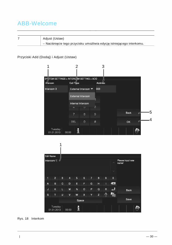
ABB-Welcome
| — 30 —
7 Adjust (Ustaw)– Naciśnięcie tego przycisku umożliwia edycję istniejącego interkomu.
Przyciski Add (Dodaj) i Adjust (Ustaw)
Rys. 18 Interkom
5
4
1 32
1
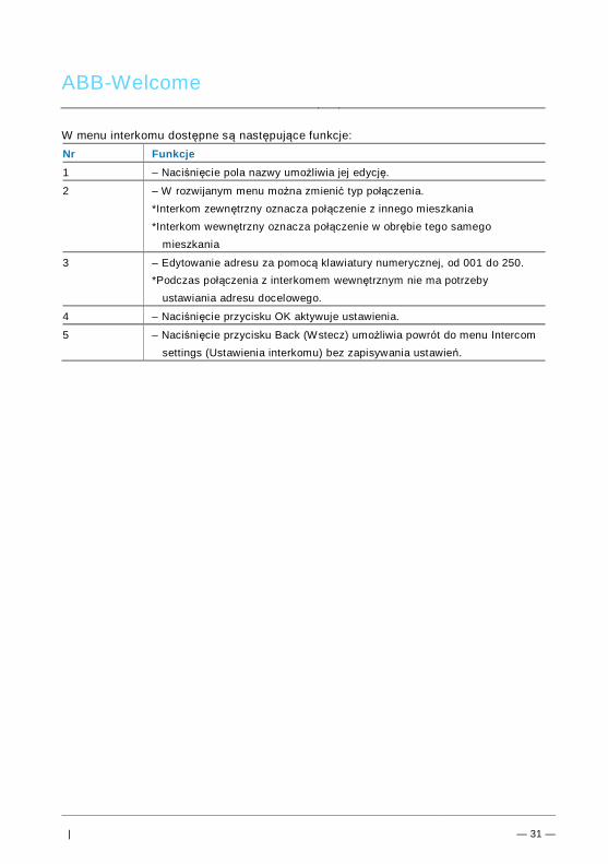
ABB-Welcome
| — 31 —
W menu interkomu dostępne są następujące funkcje:Nr Funkcje1 – Naciśnięcie pola nazwy umożliwia jej edycję.
2 – W rozwijanym menu można zmienić typ połączenia.*Interkom zewnętrzny oznacza połączenie z innego mieszkania*Interkom wewnętrzny oznacza połączenie w obrębie tego samego
mieszkania
3 – Edytowanie adresu za pomocą klawiatury numerycznej, od 001 do 250.*Podczas połączenia z interkomem wewnętrznym nie ma potrzeby
ustawiania adresu docelowego.
4 – Naciśnięcie przycisku OK aktywuje ustawienia.
5 – Naciśnięcie przycisku Back (Wstecz) umożliwia powrót do menu Intercomsettings (Ustawienia interkomu) bez zapisywania ustawień.
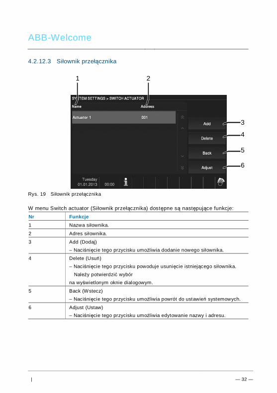
ABB-Welcome
| — 32 —
4.2.12.3 Siłownik przełącznika
Rys. 19 Siłownik przełącznika
W menu Switch actuator (Siłownik przełącznika) dostępne są następujące funkcje:Nr Funkcje1 Nazwa siłownika.
2 Adres siłownika.
3 Add (Dodaj)– Naciśnięcie tego przycisku umożliwia dodanie nowego siłownika.
4 Delete (Usuń)– Naciśnięcie tego przycisku powoduje usunięcie istniejącego siłownika.
Należy potwierdzić wybórna wyświetlonym oknie dialogowym.
5 Back (Wstecz)– Naciśnięcie tego przycisku umożliwia powrót do ustawień systemowych.
6 Adjust (Ustaw)– Naciśnięcie tego przycisku umożliwia edytowanie nazwy i adresu.
3
4
1 2
5
6
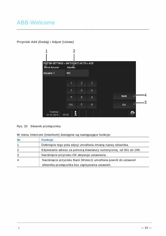
ABB-Welcome
| — 33 —
Przyciski Add (Dodaj) i Adjust (Ustaw)
Rys. 20 Siłownik przełącznika
W menu Intercom (Interkom) dostępne są następujące funkcje:Nr Funkcje1 Dotknięcie tego pola edycji umożliwia zmianę nazwy siłownika.
2 Edytowanie adresu za pomocą klawiatury numerycznej, od 001 do 199.
3 Naciśnięcie przycisku OK aktywuje ustawienia.
4 Naciśnięcie przycisku Back (Wstecz) umożliwia powrót do ustawieńsiłownika przełącznika bez zapisywania ustawień.
4
3
1 2
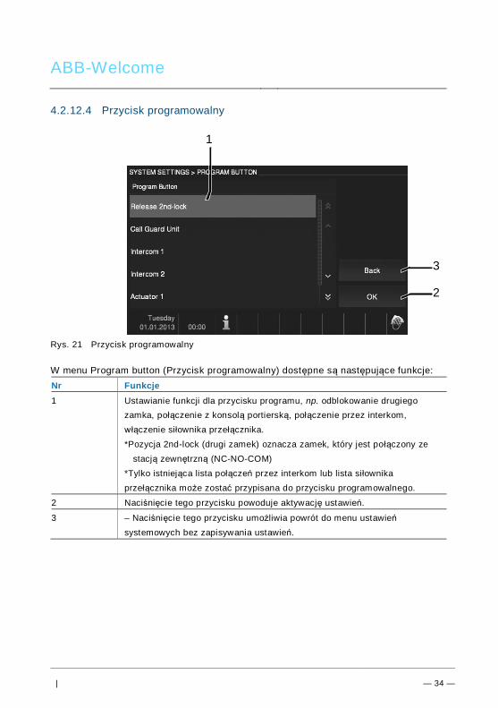
ABB-Welcome
| — 34 —
4.2.12.4 Przycisk programowalny
Rys. 21 Przycisk programowalny
W menu Program button (Przycisk programowalny) dostępne są następujące funkcje:Nr Funkcje1 Ustawianie funkcji dla przycisku programu, np. odblokowanie drugiego
zamka, połączenie z konsolą portierską, połączenie przez interkom,włączenie siłownika przełącznika.*Pozycja 2nd-lock (drugi zamek) oznacza zamek, który jest połączony ze
stacją zewnętrzną (NC-NO-COM)*Tylko istniejąca lista połączeń przez interkom lub lista siłownikaprzełącznika może zostać przypisana do przycisku programowalnego.
2 Naciśnięcie tego przycisku powoduje aktywację ustawień.
3 – Naciśnięcie tego przycisku umożliwia powrót do menu ustawieńsystemowych bez zapisywania ustawień.
3
2
1
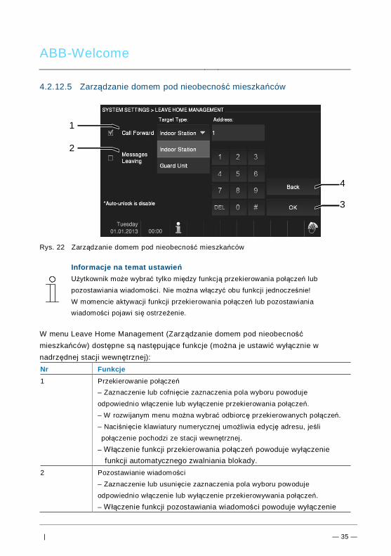
ABB-Welcome
| — 35 —
4.2.12.5 Zarządzanie domem pod nieobecność mieszkańców
Rys. 22 Zarządzanie domem pod nieobecność mieszkańców
Informacje na temat ustawieńUżytkownik może wybrać tylko między funkcją przekierowania połączeń lubpozostawiania wiadomości. Nie można włączyć obu funkcji jednocześnie!W momencie aktywacji funkcji przekierowania połączeń lub pozostawianiawiadomości pojawi się ostrzeżenie.
W menu Leave Home Management (Zarządzanie domem pod nieobecnośćmieszkańców) dostępne są następujące funkcje (można je ustawić wyłącznie wnadrzędnej stacji wewnętrznej):Nr Funkcje1 Przekierowanie połączeń
– Zaznaczenie lub cofnięcie zaznaczenia pola wyboru powodujeodpowiednio włączenie lub wyłączenie przekierowania połączeń.– W rozwijanym menu można wybrać odbiorcę przekierowanych połączeń.– Naciśnięcie klawiatury numerycznej umożliwia edycję adresu, jeślipołączenie pochodzi ze stacji wewnętrznej.
– Włączenie funkcji przekierowania połączeń powoduje wyłączeniefunkcji automatycznego zwalniania blokady.
2 Pozostawianie wiadomości– Zaznaczenie lub usunięcie zaznaczenia pola wyboru powodujeodpowiednio włączenie lub wyłączenie przekierowywania połączeń.– Włączenie funkcji pozostawiania wiadomości powoduje wyłączenie
4
3
1
2
ABB-Welcome
| — 36 —
funkcji automatycznego zwalniania blokady.*Najpierw należy ustawić wiadomość w razie nieobecności. Jeśliwiadomość w razie nieobecności nie została ustawiona, zostaniewyświetlone ostrzeżenie z informacją, aby w menu Voice Message(Wiadomość głosowa) najpierw ustawić wiadomość w razienieobecności.
3 OK– Dotknięcie tego przycisku powoduje aktywację ustawień.
4 Wstecz– Dotknięcie tego przycisku umożliwia powrót do menu ustawieńsystemowych bez zapisywania ustawień.
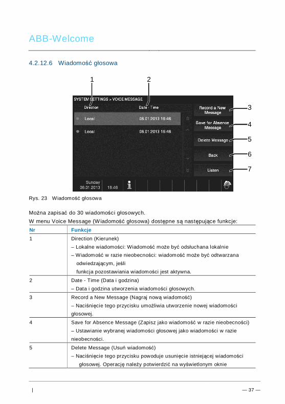
ABB-Welcome
| — 37 —
4.2.12.6 Wiadomość głosowa
Rys. 23 Wiadomość głosowa
Można zapisać do 30 wiadomości głosowych.W menu Voice Message (Wiadomość głosowa) dostępne są następujące funkcje:Nr Funkcje1 Direction (Kierunek)
– Lokalne wiadomości: Wiadomość może być odsłuchana lokalnie– Wiadomość w razie nieobecności: wiadomość może być odtwarzana
odwiedzającym, jeślifunkcja pozostawiania wiadomości jest aktywna.
2 Date - Time (Data i godzina)– Data i godzina utworzenia wiadomości głosowych.
3 Record a New Message (Nagraj nową wiadomość)– Naciśnięcie tego przycisku umożliwia utworzenie nowej wiadomościgłosowej.
4 Save for Absence Message (Zapisz jako wiadomość w razie nieobecności)– Ustawianie wybranej wiadomości głosowej jako wiadomości w razienieobecności.
5 Delete Message (Usuń wiadomość)– Naciśnięcie tego przycisku powoduje usunięcie istniejącej wiadomości
głosowej. Operację należy potwierdzić na wyświetlonym oknie
6
7
1 2
3
4
5
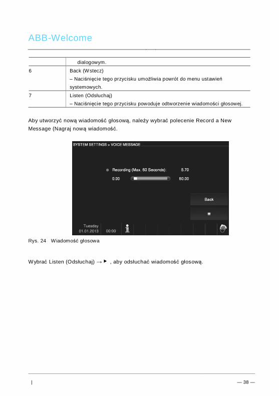
ABB-Welcome
| — 38 —
dialogowym.
6 Back (Wstecz)– Naciśnięcie tego przycisku umożliwia powrót do menu ustawieńsystemowych.
7 Listen (Odsłuchaj)– Naciśnięcie tego przycisku powoduje odtworzenie wiadomości głosowej.
Aby utworzyć nową wiadomość głosową, należy wybrać polecenie Record a NewMessage (Nagraj nową wiadomość.
Rys. 24 Wiadomość głosowa
Wybrać Listen (Odsłuchaj) → ▶ , aby odsłuchać wiadomość głosową.
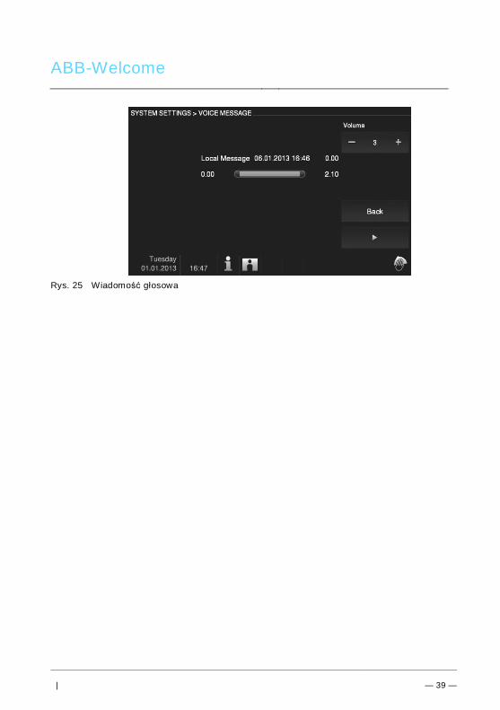
ABB-Welcome
| — 39 —
Rys. 25 Wiadomość głosowa
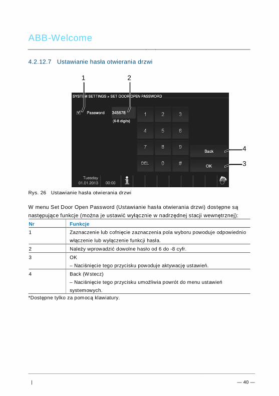
ABB-Welcome
| — 40 —
4.2.12.7 Ustawianie hasła otwierania drzwi
Rys. 26 Ustawianie hasła otwierania drzwi
W menu Set Door Open Password (Ustawianie has ła otwierania drzwi) dostępne sąnastępujące funkcje (można je ustawić wyłącznie w nadrzędnej stacji wewnętrznej):Nr Funkcje1 Zaznaczenie lub cofnięcie zaznaczenia pola wyboru powoduje odpowiednio
włączenie lub wyłączenie funkcji hasła.
2 Należy wprowadzić dowolne hasło od 6 do -8 cyfr.
3 OK– Naciśnięcie tego przycisku powoduje aktywację ustawień.
4 Back (Wstecz)– Naciśnięcie tego przycisku umożliwia powrót do menu ustawieńsystemowych.
*Dostępne tylko za pomocą klawiatury.
4
3
21
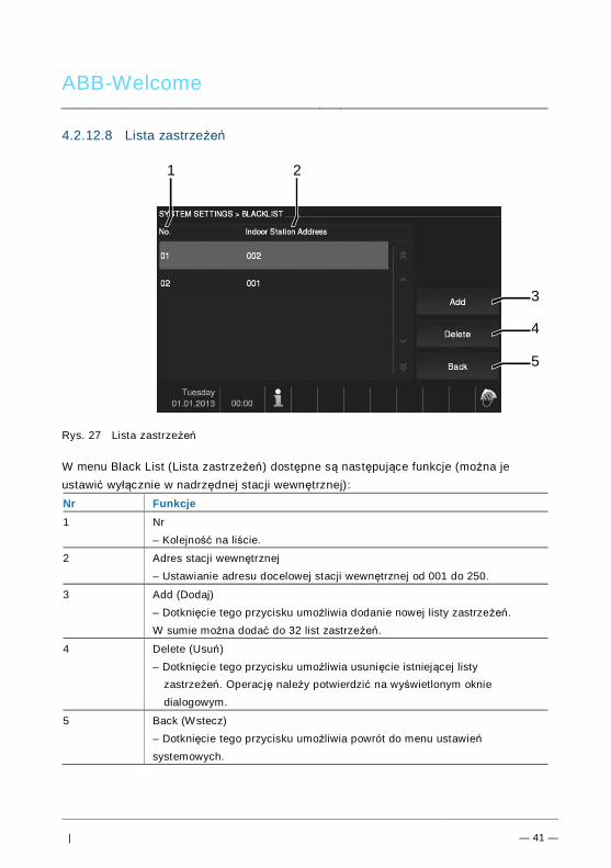
ABB-Welcome
| — 41 —
4.2.12.8 Lista zastrzeżeń
Rys. 27 Lista zastrzeżeń
W menu Black List (Lista zastrzeżeń) dostępne są następujące funkcje (można jeustawić wyłącznie w nadrzędnej stacji wewnętrznej):Nr Funkcje1 Nr
– Kolejność na liście.
2 Adres stacji wewnętrznej– Ustawianie adresu docelowej stacji wewnętrznej od 001 do 250.
3 Add (Dodaj)– Dotknięcie tego przycisku umożliwia dodanie nowej listy zastrzeżeń.W sumie można dodać do 32 list zastrzeżeń.
4 Delete (Usuń)– Dotknięcie tego przycisku umożliwia usunięcie istniejącej listy
zastrzeżeń. Operację należy potwierdzić na wyświetlonym okniedialogowym.
5 Back (Wstecz)– Dotknięcie tego przycisku umożliwia powrót do menu ustawieńsystemowych.
4
5
1 2
3
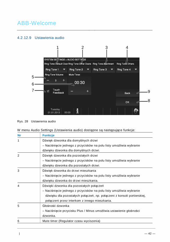
ABB-Welcome
| — 42 —
4.2.12.9 Ustawienia audio
Rys. 28 Ustawienia audio
W menu Audio Settings (Ustawienia audio) dostępne są następujące funkcje:Nr Funkcje1 Dźwięk dzwonka dla domyślnych drzwi
– Naciśnięcie jednego z przycisków na polu listy umożliwia wybraniedźwięku dzwonka dla domyślnych drzwi.
2 Dźwięk dzwonka dla pozostałych drzwi– Naciśnięcie jednego z przycisków na polu listy umożliwia wybraniedźwięku dzwonka dla pozostałych drzwi.
3 Dźwięk dzwonka do drzwi mieszkania– Naciśnięcie jednego z przycisków na polu listy umożliwia wybraniedźwięku dzwonka do drzwi mieszkania.
4 Dźwięki dzwonka dla pozostałych połączeń– Naciśnięcie jednego z przycisków na polu listy umożliwia wybranie
dźwięku dla pozostałych połączeń, np. połączeni z konsoli portierskiej,połączeni przez interkom z innego mieszkania.
5 Głośność dzwonka– Naciśnięcie przycisku Plus / Minus umożliwia ustawienie głośnościdzwonka.
6 Mute timer (Regulator czasu wyciszenia)
9
8
1 2
5
3 4
67
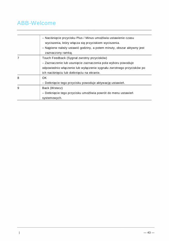
ABB-Welcome
| — 43 —
– Naciśnięcie przycisku Plus / Minus umożliwia ustawienie czasuwyciszenia, który w łącza się przyciskiem wyciszenia.
– Najpierw należy ustawić godziny, a potem minuty, obszar aktywny jestzaznaczony ramką.
7 Touch Feedback (Sygnał zwrotny przycisków)– Zaznaczenie lub usunięcie zaznaczenia pola wyboru powodujeodpowiednio włączenie lub wyłączenie sygnału zwrotnego przycisków poich naciśnięciu lub dotknięciu na ekranie.
8 OK– Dotknięcie tego przycisku powoduje aktywację ustawień.
9 Back (Wstecz)– Dotknięcie tego przycisku umożliwia powrót do menu ustawieńsystemowych.
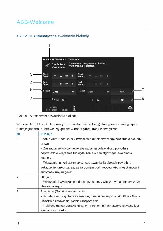
ABB-Welcome
| — 44 —
4.2.12.10 Automatyczne zwalnianie blokady
Rys. 29 Automatyczne zwalnianie blokady
W menu Auto Unlock (Automatyczne zwalnianie blokady) dostępne są następującefunkcje (można je ustawić wyłącznie w nadrzędnej stacji wewnętrznej):Nr Funkcje1 Enable Auto Door Unlock (W łączanie automatycznego zwalniania blokady
drzwi)– Zaznaczenie lub cofnięcie zaznaczenia pola wyboru powodujeodpowiednio włączenie lub wyłączenie automatycznego zwalnianiablokady.– W łączenie funkcji automatycznego zwalniania blokady powodujewyłączenie funkcji zarządzania domem pod nieobecność mieszkańców iautomatycznej migawki.
2 On (W ł.)– W łączanie i wyłączanie zakresu czasu przy w łączonym automatycznymelektrozaczepie.
3 Start time (Godzina rozpoczęcia)– Po włączeniu regulatora czasowego naciśnięcie przycisku Plus / Minusumożliwia ustawienie godziny rozpoczęcia.– Najpierw należy ustawić godziny, a potem minuty, zakres aktywny jestzaznaczony ramką.
7
6
3
1
4
5
2
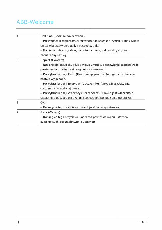
ABB-Welcome
| — 45 —
4 End time (Godzina zakończenia)– Po włączeniu regulatora czasowego naciśnięcie przycisku Plus / Minusumożliwia ustawienie godziny zakończenia.– Najpierw ustawić godziny, a potem minuty, zakres aktywny jestzaznaczony ramką.
5 Repeat (Powtórz)– Naciśnięcie przycisku Plus / Minus umożliwia ustawienie częstotliwościpowtarzania po włączeniu regulatora czasowego.– Po wybraniu opcji Once (Raz), po upływie ustalonego czasu funkcjazostaje wyłączona.– Po wybraniu opcji Everyday (Codziennie), funkcja jest włączanacodziennie o ustalonej porze.– Po wybraniu opcji Weekday (Dni robocze), funkcja jest w łączana oustalonej porze, ale tylko w dni robocze (od poniedziałku do piątku).
6 OK– Dotknięcie tego przycisku powoduje aktywację ustawień.
7 Back (Wstecz)– Dotknięcie tego przycisku umożliwia powrót do menu ustawieńsystemowych bez zapisywania ustawień.
Pos: 32 /B usch-J aeg er (Neus truk tur )/M odul -Strukt ur/O nline -Doku me ntatio n/Steu er mod ule - Onlin e-Dok ume ntati on ( -- > Für alle Dok ume nte <- -)/ +++ ++ ++ +++ ++ S eiten umb ruch + +++ ++ ++ +++ + @ 9\m od_ 126 8898 668 093 _0. docx @ 521 49 @ @ 1
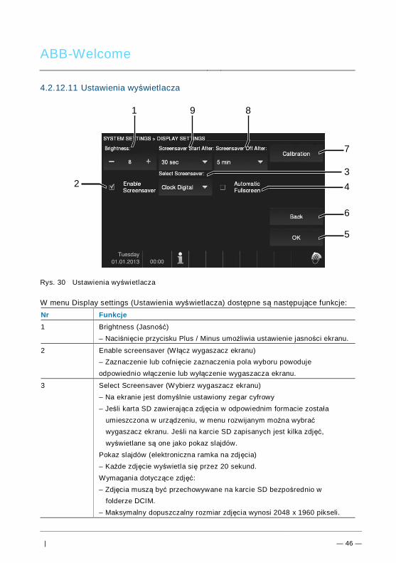
ABB-Welcome
| — 46 —
4.2.12.11 Ustawienia wyświetlacza
Rys. 30 Ustawienia wyświetlacza
W menu Display settings (Ustawienia wyświetlacza) dostępne są następujące funkcje:Nr Funkcje1 Brightness (Jasność)
– Naciśnięcie przycisku Plus / Minus umożliwia ustawienie jasności ekranu.
2 Enable screensaver (W łącz wygaszacz ekranu)– Zaznaczenie lub cofnięcie zaznaczenia pola wyboru powodujeodpowiednio włączenie lub wyłączenie wygaszacza ekranu.
3 Select Screensaver (Wybierz wygaszacz ekranu)– Na ekranie jest domyślnie ustawiony zegar cyfrowy– Jeśli karta SD zawierająca zdjęcia w odpowiednim formacie została
umieszczona w urządzeniu, w menu rozwijanym można wybraćwygaszacz ekranu. Jeśli na karcie SD zapisanych jest kilka zdjęć,wyświetlane są one jako pokaz slajdów.
Pokaz slajdów (elektroniczna ramka na zdjęcia)– Każde zdjęcie wyświetla się przez 20 sekund.Wymagania dotyczące zdjęć:– Zdjęcia muszą być przechowywane na karcie SD bezpośrednio w
folderze DCIM.– Maksymalny dopuszczalny rozmiar zdjęcia wynosi 2048 x 1960 pikseli.
6
5
1 9 8
7
234
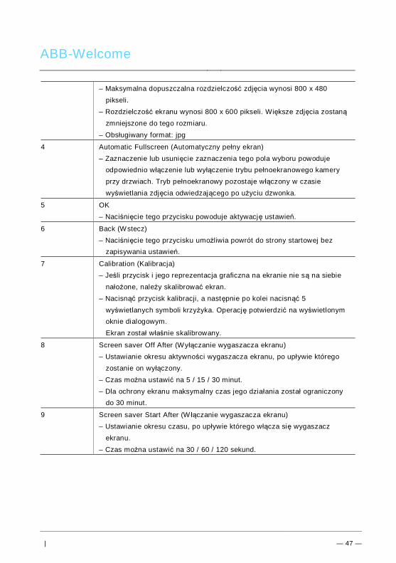
ABB-Welcome
| — 47 —
– Maksymalna dopuszczalna rozdzielczość zdjęcia wynosi 800 x 480pikseli.
– Rozdzielczość ekranu wynosi 800 x 600 pikseli. Większe zdjęcia zostanązmniejszone do tego rozmiaru.
– Obsługiwany format: jpg
4 Automatic Fullscreen (Automatyczny pełny ekran)– Zaznaczenie lub usunięcie zaznaczenia tego pola wyboru powoduje
odpowiednio włączenie lub wyłączenie trybu pełnoekranowego kameryprzy drzwiach. Tryb pełnoekranowy pozostaje włączony w czasiewyświetlania zdjęcia odwiedzającego po użyciu dzwonka.
5 OK– Naciśnięcie tego przycisku powoduje aktywację ustawień.
6 Back (Wstecz)– Naciśnięcie tego przycisku umożliwia powrót do strony startowej bez
zapisywania ustawień.
7 Calibration (Kalibracja)– Jeśli przycisk i jego reprezentacja graficzna na ekranie nie są na siebie
nałożone, należy skalibrować ekran.– Nacisnąć przycisk kalibracji, a następnie po kolei nacisnąć 5
wyświetlanych symboli krzyżyka. Operację potwierdzić na wyświetlonymoknie dialogowym.
Ekran został właśnie skalibrowany.
8 Screen saver Off After (Wyłączanie wygaszacza ekranu)– Ustawianie okresu aktywności wygaszacza ekranu, po upływie którego
zostanie on wyłączony.– Czas można ustawić na 5 / 15 / 30 minut.– Dla ochrony ekranu maksymalny czas jego działania został ograniczony
do 30 minut.
9 Screen saver Start After (W łączanie wygaszacza ekranu)– Ustawianie okresu czasu, po upływie którego włącza się wygaszacz
ekranu.– Czas można ustawić na 30 / 60 / 120 sekund.
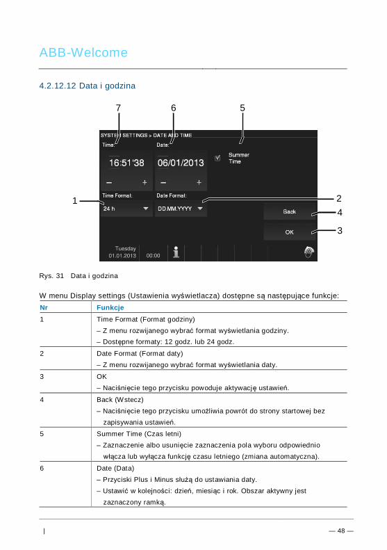
ABB-Welcome
| — 48 —
4.2.12.12 Data i godzina
Rys. 31 Data i godzina
W menu Display settings (Ustawienia wyświetlacza) dostępne są następujące funkcje:Nr Funkcje1 Time Format (Format godziny)
– Z menu rozwijanego wybrać format wyświetlania godziny.– Dostępne formaty: 12 godz. lub 24 godz.
2 Date Format (Format daty)– Z menu rozwijanego wybrać format wyświetlania daty.
3 OK– Naciśnięcie tego przycisku powoduje aktywację ustawień.
4 Back (Wstecz)– Naciśnięcie tego przycisku umożliwia powrót do strony startowej bez
zapisywania ustawień.
5 Summer Time (Czas letni)– Zaznaczenie albo usunięcie zaznaczenia pola wyboru odpowiednio
włącza lub wyłącza funkcję czasu letniego (zmiana automatyczna).
6 Date (Data)– Przyciski Plus i Minus służą do ustawiania daty.– Ustawić w kolejności: dzień, miesiąc i rok. Obszar aktywny jest
zaznaczony ramką.
4
3
7 6 5
1 2
ABB-Welcome
| — 49 —
7 Time (Godzina)Przyciski Plus i Minus służą do ustawiania godziny.– Ustawić w kolejności godziny, minuty i sekundy, obszar aktywny jest
zaznaczony ramką.
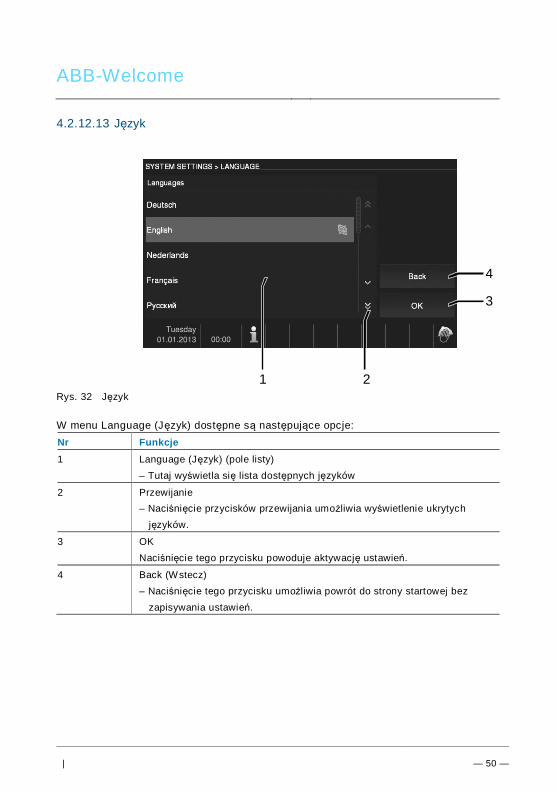
ABB-Welcome
| — 50 —
4.2.12.13 Język
Rys. 32 Język
W menu Language (Język) dostępne są następujące opcje:Nr Funkcje1 Language (Język) (pole listy)
– Tutaj wyświetla się lista dostępnych języków
2 Przewijanie– Naciśnięcie przycisków przewijania umożliwia wyświetlenie ukrytych
języków.
3 OKNaciśnięcie tego przycisku powoduje aktywację ustawień.
4 Back (Wstecz)– Naciśnięcie tego przycisku umożliwia powrót do strony startowej bez
zapisywania ustawień.
4
3
1 2
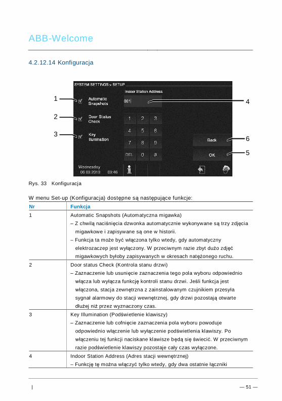
ABB-Welcome
| — 51 —
4.2.12.14 Konfiguracja
Rys. 33 Konfiguracja
W menu Set-up (Konfiguracja) dostępne są następujące funkcje:Nr Funkcja1 Automatic Snapshots (Automatyczna migawka)
– Z chwilą naciśnięcia dzwonka automatycznie wykonywane są trzy zdjęciamigawkowe i zapisywane są one w historii.
– Funkcja ta może być włączona tylko wtedy, gdy automatycznyelektrozaczep jest wyłączony. W przeciwnym razie zbyt dużo zdjęćmigawkowych byłoby zapisywanych w okresach natężonego ruchu.
2 Door status Check (Kontrola stanu drzwi)– Zaznaczenie lub usunięcie zaznaczenia tego pola wyboru odpowiednio
włącza lub wyłącza funkcję kontroli stanu drzwi. Jeśli funkcja jestwłączona, stacja zewnętrzna z zainstalowanym czujnikiem przesyłasygnał alarmowy do stacji wewnętrznej, gdy drzwi pozostają otwartedłużej niż przez wyznaczony czas.
3 Key Illumination (Podświetlenie klawiszy)– Zaznaczenie lub cofnięcie zaznaczenia pola wyboru powoduje
odpowiednio włączenie lub wyłączenie podświetlenia klawiszy. Powłączeniu tej funkcji naciskane klawisze będą się świecić. W przeciwnymrazie podświetlenie klawiszy pozostaje cały czas wyłączone.
4 Indoor Station Address (Adres stacji wewnętrznej)– Funkcję tę można włączyć tylko wtedy, gdy dwa ostatnie łączniki
6
5
1
2
3
4
ABB-Welcome
| — 52 —
pokrętne stacji wewnętrznej są ustawione na 00. Adres można ustawić wzakresie od 001 do 250.
5 OK– Naciśnięcie tego przycisku powoduje aktywację ustawień.
6 Back (Wstecz)– Naciśnięcie tego przycisku umożliwia powrót do strony startowej bez
zapisywania ustawień.
ABB-Welcome
| — 53 —
4.2.12.15 Aktualizacja oprogramowania układowego
Aby zaktualizować oprogramowanie układowe urządzenia należy wykonać następującekroki:1. Od instalatora instalacji elektrycznej uzyskać nową wersję oprogramowania
układowego i skopiować ją na kartę SD.2. Włożyć kartę SD do gniazda znajdującego się w stacji wewnętrznej.3. Wybrać opcję Firmware Update (Aktualizacja oprogramowania układowego).4. Wykonać aktualizację oprogramowania układowego, wybierając opcję
Updating (Aktualizacja).5. Na wyskakującym oknie zaznaczyć pozycję Yes (Tak).Pos: 67 /Di nA4 - A nleitu ngen Onlin e/Ueb ersc hrift en/2 ./Reini gung @ 1 9\m od_ 131 0733 980 533 _15. docx @ 10 785 3 @ 2 @ 1
ABB-Welcome
| — 54 —
4.3 CzyszczeniePos: 68 /Di nA4 - A nleitu ngen Onlin e/In halt/KNX/Do orEnt ry/Reini gun g/Reini gun g Touchsc ree nm onito r @ 19\m od_ 131 073 410 897 8_15 .docx @ 1 078 62 @ @ 1
OstrzeżenieRyzyko uszkodzenia powierzchni ekranu.Powierzchnię ekranu można uszkodzić twardymi lub ciężkimiprzedmiotami!Nigdy nie należy stosować takich przedmiotów do obsługi ekranudotykowego.– Używać palca lub plastikowego rysika.
Powierzchnię ekranu można uszkodzić, stosując płyny do czyszczenialub środki ścierne!– Powierzchnie czyścić, używając miękkiej ściereczki lub dostępnego
w sprzedaży płynu do mycia okien.– Nigdy nie stosować środków czystości ze środkiem ściernym.
Pos: 69 /B usch-J aeg er (Neus truk tur )/M odul -Strukt ur/O nline -Doku me ntatio n/Steu er mod ule - Onlin e-Dok ume ntati on ( -- > Für alle Dok ume nte <- -)/ +++ ++ ++ +++ ++ S eiten umb ruch + +++ ++ ++ +++ + @ 9\m od_ 126 8898 668 093 _0. docx @ 521 49 @ @ 1
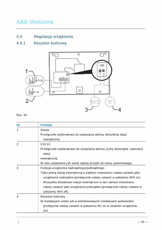
ABB-Welcome
| — 55 —
Pos: 70 /Di nA4 - A nleitu ngen Onlin e/Ueb ersc hrift en/2 ./Ge raet eeins tellun gen @ 1 8\mo d_1 302 768 847 744 _15. docx @ 10 354 8 @ 2 @ 1
4.4 Regulacja urządzeniaPos: 71 /Di nA4 - A nleitu ngen Onlin e/Ueb ersc hrift en/3 ./Abschl usswide rsta nd @ 19\ mod _13 219 5807 990 6_1 5.do cx @ 1100 83 @ 3 @ 1
Pos: 72 /Di nA4 - A nleitu ngen Onlin e/In halt/KNX/Do orEnt ry/Bedie nun g/Abschl usswide rsta nd s etzen 83 220 -AP-xxx @ 19\ mod _13 1072 339 236 9_1 5.do cx @ 1 078 41 @ @ 1
4.4.1 Rezystor końcowy
Rys. 34Pos: 74 /Di nA4 - A nleitu ngen Onlin e/In halt/KNX/Do orEnt ry/Bedie nun g/M aste r/Slave Sc halte r setz en 832 20-AP-xxx @ 1 9\m od_1 310 723 320 966 _15. docx @ 10 783 3 @ @
Nr Funkcje1 Stacja
Przełącznik wybierakowy do ustawiania adresu domyślnej stacjizewnętrznej.
2 X10 X1Przełączniki wybierakowe do ustawiania adresu (cyfry dziesiątek i jedności)
stacjiwewnętrznej.W celu ustawienia cyfr setek należy przejść do menu systemowego.
3 Funkcja urządzenia nadrzędnego/podrzędnegoTylko jedną stację wewnętrzną w każdym mieszkaniu należy ustawić jako
urządzenie nadrzędne (przełącznik należy ustawić w położeniu M/S on).Wszystkie dodatkowe stacje wewnętrzne w tym samym mieszkaniunależy ustawić jako urządzenia podrzędne (przełącznik należy ustawić wpołożeniu M/S off).
4 Rezystor końcowyW instalacjach wideo lub w kombinowanych instalacjach audio/wideo
przełącznik należy ustawić w położeniu RC on w ostatnim urządzeniulinii.
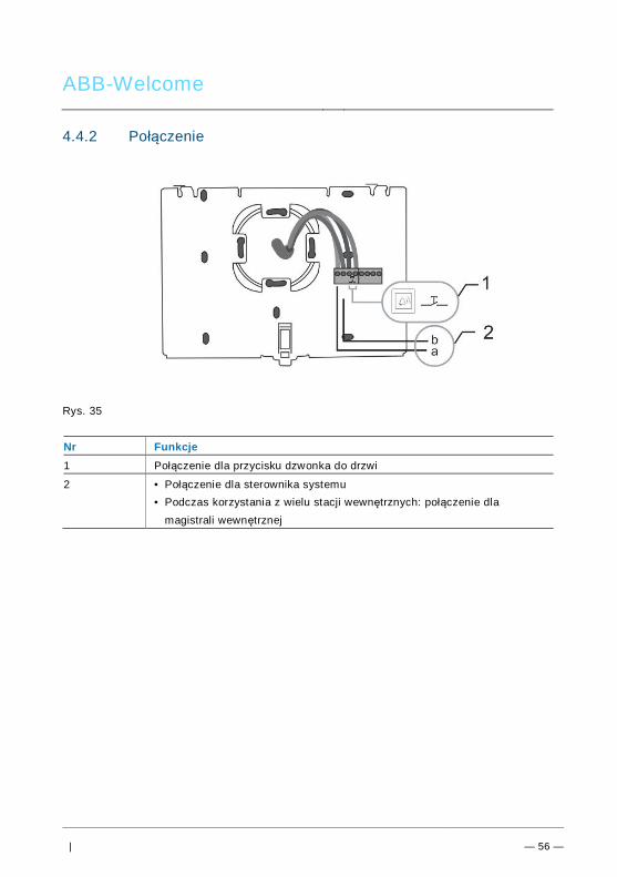
ABB-Welcome
| — 56 —
4.4.2 Połączenie
Rys. 35
Nr Funkcje1 Połączenie dla przycisku dzwonka do drzwi
2 • Połączenie dla sterownika systemu• Podczas korzystania z wielu stacji wewnętrznych: połączenie dla
magistrali wewnętrznej
Pos: 75 /B usch-J aeg er (Neus truk tur )/M odul -Strukt ur/O nline -Doku me ntatio n/Steu er mod ule - Onlin e-Dok ume ntati on ( -- > Für alle Dok ume nte <- -)/ +++ ++ ++ +++ ++ S eiten umb ruch + +++ ++ ++ +++ + @ 9\m od_ 126 8898 668 093 _0. docx @ 521 49 @ @ 1
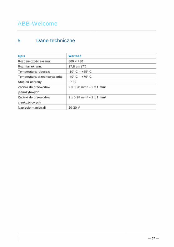
ABB-Welcome
| — 57 —
Pos: 76 /Di nA4 - A nleitu ngen Onlin e/Ueb ersc hrift en/1 ./Technisc he D aten @ 18 \mo d_1 302 615 863 001 _15. docx @ 10 341 6 @ 1 @ 1
5 Dane technicznePos: 77 /Di nA4 - A nleitu ngen Onlin e/In halt/KNX/Do orEnt ry/83 220 -AP-xxx/ Tech nische Date n - 832 20-AP-x xx @ 1 8\m od_ 130 321 285 4559 _15 .docx @ 1 037 05 @ @ 1
Opis WartośćRozdzielczość ekranu: 800 × 480
Rozmiar ekranu: 17,8 cm (7")
Temperatura robocza: -10° C – +55° CTemperatura przechowywania: -40° C – +70° C
Stopień ochrony IP 30
Zaciski do przewodówjednożyłowych
2 x 0,28 mm² – 2 x 1 mm²
Zaciski do przewodówcienkożyłowych
2 x 0,28 mm² – 2 x 1 mm²
Napięcie magistrali 20-30 V
Pos: 78 /B usch-J aeg er (Neus truk tur )/M odul -Strukt ur/O nline -Doku me ntatio n/Steu er mod ule - Onlin e-Dok ume ntati on ( -- > Für alle Dok ume nte <- -)/ +++ ++ ++ +++ ++ S eiten umb ruch + +++ ++ ++ +++ + @ 9\m od_ 126 8898 668 093 _0. docx @ 521 49 @ @ 1
ABB-Welcome
| — 58 —
Pos: 79 /B usch-J aeg er (Neus truk tur )/M odul -Strukt ur/O nline -Doku me ntatio n/Übe rsch rifte n ( --> Fü r alle Doku men te < -- )/1. E bene /M - O/ Mont age / Ins tallatio n @ 18\ mod _13 0261 396 611 1_1 5.do cx @ 1 033 73 @ 1 @ 1
6 Montaż / instalacjaPos: 80 /B usch-J aeg er (Neus truk tur )/M odul -Strukt ur/O nline -Doku me ntatio n/Siche rheit (- -> Fü r alle D oku ment e < --) /War nhinweis e/Siche rheit - Nie ders pan nun gs- und 230 V-Leit ung en @ 18\ mod _13 026 178 214 91_1 5.d ocx @ 103 465 @ @ 1
OstrzeżenieNapięcie elektryczne!Ryzyko śmierci i pożaru z powodu napięcia elektrycznego równego100–240 V.– Przewodów niskonapięciowych i 100–240 V nie wolno układać
razem w jednej puszce podtynkowej!Jeśli dojdzie do zwarcia, istnieje niebezpieczeństwo wystąpienianapięcia 100–240 V w przewodach niskonapięciowych.
Pos: 81 /B usch-J aeg er (Neus truk tur )/M odul -Strukt ur/O nline -Doku me ntatio n/Siche rheit (- -> Fü r alle D oku ment e < --) /War nhinweis e/Siche rheit - Fachk enn tnisse @ 18 \mo d_1 302 774 384 017_ 15. docx @ 10 356 4 @ 2 @ 1
6.1 Wymagania wobec elektryków
OstrzeżenieNapięcie elektryczne!Urządzenie wolno instalować jedynie osobom posiadającym koniecznąwiedzę i doświadczenie w dziedzinie elektrotechniki.• Niefachowa instalacja zagraża życiu instalatora i użytkowników
instalacji elektrycznej.• Niefachowa instalacja może prowadzić do poważnych szkód
rzeczowych, na przykład pożaru.Wymagana wiedza fachowa i warunki instalacji:• Stosować poniższe zasady bezpieczeństwa (DIN VDE 0105, EN
50110):1. Odłączyć od sieci.2. Zabezpieczyć przed ponownym włączeniem.3. Sprawdzić, czy urządzenie nie jest pod napięciem.4. Podłączyć do uziemienia.5. Zakryć lub odgrodzić sąsiadujące części znajdujące się podnapięciem.
• Stosować odpowiednią odzież ochronną.• Stosować wyłącznie odpowiednie narzędzia i przyrządy pomiarowe.• Sprawdzić rodzaj sieci zasilającej (system TN, system IT i system
TT) i przestrzegać wynikających z tego warunków przyłączenia
ABB-Welcome
| — 59 —
(klasyczne zerowanie, uziemienie ochronne, koniecznośćwykonania dodatkowych pomiarów, itd.).
Pos: 82 /Di nA4 - A nleitu ngen Onlin e/In halt/KNX/Do orEnt ry/M onta ge/ Mont age hinweis e - Allg emei n @ 1 9\m od_ 131 056 367 047 8_15 .docx @ 1 077 43 @ 2 @ 1
6.2 Ogólna instrukcja montażu• Wszystkie odgałęzienia przewodów powinny zostać zakończone podłączonym
urządzeniem magistrali (np. stacja wewnętrzna, zewnętrzna lub urządzeniesystemowe).
• Nie instalować centrali systemu bezpośrednio obok transformatorów dzwonka lubinnych urządzeń zasilających (unikanie interferencji).
• Nie układać przewodów magistrali systemowej wspólnie z przewodami 100–240 V.• Nie używać wspólnego kabla dla przewodów przyłączowych elektrozaczepów i
przewodów magistrali systemowej.• Unikać złączeń między różnymi typami kabli.• W kablu, który ma cztery lub więcej żył, do magistrali systemowej należy
wykorzystać tylko dwie żyły.• Przy łączeniu przelotowym nigdy nie prowadzić przychodzącej i wychodzącej
magistrali w tym samym kablu.• Nigdy nie prowadzić magistrali wewnętrznej i zewnętrznej w tym samym kablu.Pos: 83 /B usch-J aeg er (Neus truk tur )/M odul -Strukt ur/O nline -Doku me ntatio n/Steu er mod ule - Onlin e-Dok ume ntati on ( -- > Für alle Dok ume nte <- -)/ +++ ++ ++ +++ ++ S eiten umb ruch + +++ ++ ++ +++ + @ 9\m od_ 126 8898 668 093 _0. docx @ 521 49 @ @ 1
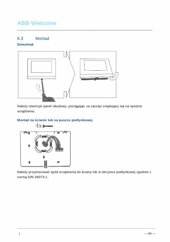
ABB-Welcome
| — 60 —
Pos: 84 /B usch-J aeg er (Neus truk tur )/M odul -Strukt ur/O nline -Doku me ntatio n/Übe rsch rifte n ( --> Fü r alle Doku men te < -- )/2. E bene /M - O/ Mont age @ 1 8\m od_1 302 615 960 458 _15. docx @ 10 342 4 @ 2 @ 1
6.3 MontażPos: 85. 1 /DinA4 - Anleit ung en O nline/I nhal t/KNX/DoorE ntry/ 832 20-AP-xxx /Mo nta ge - Mo dule/ Mon tag e - Mon tage dos e -- 83 220 -AP-xxx @ 19\ mod _132 325 040 684 8_1 5.doc x @ 1 110 98 @ @ 1
Demontaż
Należy otworzyć panel obudowy, pociągając za zaczep znajdujący się na spodzieurządzenia.
Montaż na ścianie lub na puszce podtynkowej
Należy przymocować spód urządzenia do ściany lub w skrzynce podtynkowej zgodnie znormą DIN 49073-1.
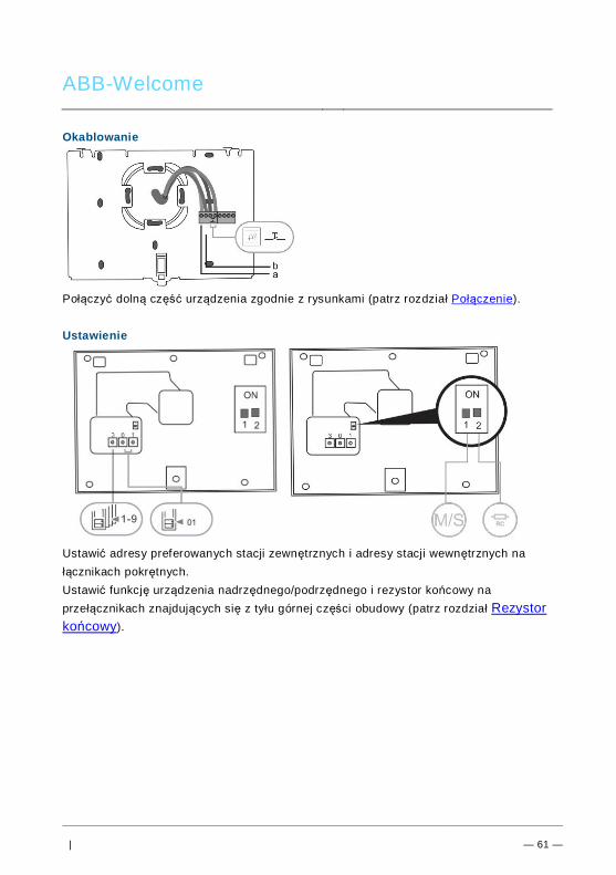
ABB-Welcome
| — 61 —
Okablowanie
Połączyć dolną część urządzenia zgodnie z rysunkami (patrz rozdział Połączenie).
Ustawienie
Ustawić adresy preferowanych stacji zewnętrznych i adresy stacji wewnętrznych nałącznikach pokrętnych.Ustawić funkcję urządzenia nadrzędnego/podrzędnego i rezystor końcowy naprzełącznikach znajdujących się z tyłu górnej części obudowy (patrz rozdział Rezystorkońcowy).
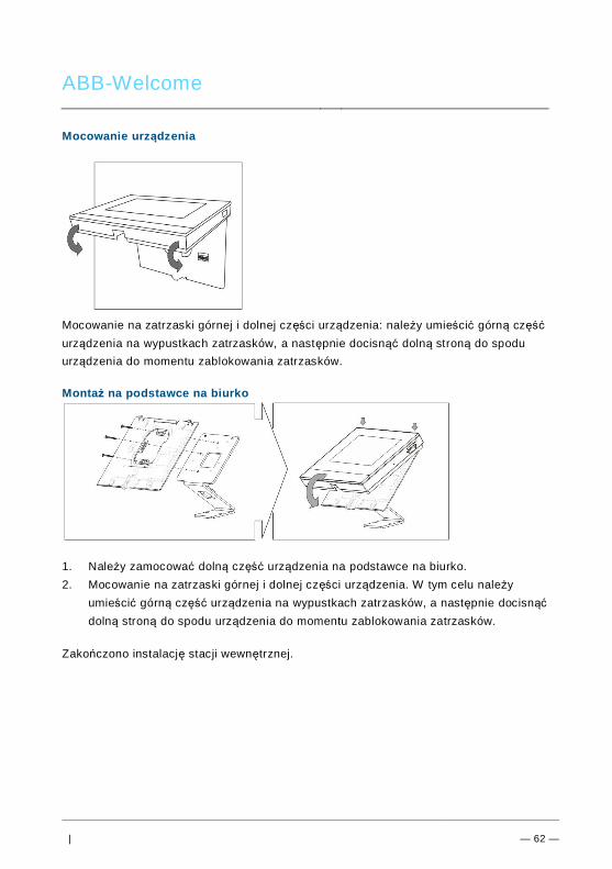
ABB-Welcome
| — 62 —
Mocowanie urządzenia
Mocowanie na zatrzaski górnej i dolnej części urządzenia: należy umieścić górną częśćurządzenia na wypustkach zatrzasków, a następnie docisnąć dolną stroną do spoduurządzenia do momentu zablokowania zatrzasków.
Montaż na podstawce na biurko
1. Należy zamocować dolną część urządzenia na podstawce na biurko.2. Mocowanie na zatrzaski górnej i dolnej części urządzenia. W tym celu należy
umieścić górną część urządzenia na wypustkach zatrzasków, a następnie docisnąćdolną stroną do spodu urządzenia do momentu zablokowania zatrzasków.
Zakończono instalację stacji wewnętrznej.
Pos: 94 /B usch-J aeg er (Neus truk tur )/M odul -Strukt ur/O nline -Doku me ntatio n/Steu er mod ule - Onlin e-Dok ume ntati on ( -- > Für alle Dok ume nte <- -)/ +++ ++ ++ +++ ++ S eiten umb ruch + +++ ++ ++ +++ + @ 9\m od_ 126 8898 668 093 _0. docx @ 521 49 @ @ 1
ABB-Welcome M Error! Use the Home tab
to apply 标题 1 to the
text that you want to
appear here.
| — 63 —
Pos: 95 /Di nA4 - A nleitu ngen Onlin e/In halt/KNX/Do orEnt ry/Proj ektier ung -M erkbl att/Pr ojektie rPos: 9 7 /Busc h-Ja ege r (N eust ruktu r)/ Mo dul-Str uktu r/Onli ne-D oku ment ation /Rückseit en (-- > Für alle Dok um ente <- -)/R ückseit e - Bus ch-J aeg er - Allgem ein @ 20\ mod _13 273 200 748 86_1 5.d ocx @ 137 103 @ @ 1
Uwaga=== E nde der Liste für Tex tma rke Ba ckcove r = ==
Firma ABB zastrzega sobie prawo do wprowadzania zmian technicznych, jak równieżzmian treści niniejszego dokumentu w dowolnym momencie i bez uprzedzenia.Szczegółowe dane techniczne uzgodnione w czasie składania zamówienia stosuje siędo wszystkich zamówień. Firma ABB nie ponosi żadnej odpowiedzialności za błędy aniza braki, jakie mogą pojawić się w niniejszym dokumencie. Wszelkie prawa do niniejszego dokumentu i zawartych w nim informacji są zastrzeżone.Osobom trzecim zabrania się powielania, przesyłania czy ponownego wykorzystywanianiniejszego dokumentu lub jego części bez uprzedniej pisemnej zgody firmy ABB.