lwm 4.1 low voltage cable jointing - sp energy networks · this section of the live working manual...
TRANSCRIPT
LOW VOLTAGE CABLE JOINTING
OPSAF-12-011
Issue No. 7
© SP Power Systems Limited Page 1 of 20 LWM 4.1
1. SCOPE
This section of the Live Working Manual details generalised procedures to be followed when Live Low Voltage cable jointing is to be carried out. The procedures apply the principles established by the ScottishPower Safety Rules (Electrical and Mechanical) to achieve Safety from the System and in particular OPSAF-10-012 (PSSI 12) - Low Voltage Apparatus.
2. ISSUE RECORD
This is a Reference document. The current version is held on the EN Document Library. It is your responsibility to ensure you work to the current version.
Issue Date Issue No Author Amendment Details
November 2009 6 Only published to the Intranet
Clark Sherry Document Reviewed and updated to include new and revised practices and techniques. Procedure for Temporary Jointing added
July 2019 7 Colin Rundell Document thoroughly updated. Section 7: general update including justification, PPE and accompaniment 7.14: table added giving guidance on glove use 9.2: testing voltage conditions added 9.3: cutting live cables added Procedures WL 1.10 to WL 1.14: general updates Procedure WL 1.16 withdrawn (breaking down oil or compound filled joints) Procedure WL1.19: general update Section 16: general update
3. ISSUE AUTHORITY
Author Owner Issue Authority
Colin Rundell Operational Safety Engineer
Gary Evans Operational Assurance Manager
Frank Monaghan Health and Safety Director
4. REVIEW
This is a Reference document which has a 5 year retention period after which a reminder will be issued to review and extend retention or archive.
DISTRIBUTION
This document is part of the Live Working Manual but does not have a maintained distribution list.

LOW VOLTAGE CABLE JOINTING
OPSAF-12-011
Issue No. 7
© SP Power Systems Limited Page 2 of 20 LWM 4.1
5. CONTENT
1. SCOPE .......................................................................................................................................... 1
2. ISSUE RECORD ........................................................................................................................... 1
3. ISSUE AUTHORITY....................................................................................................................... 1
4. REVIEW ........................................................................................................................................ 1
DISTRIBUTION ...................................................................................................................................... 1
5. CONTENT ..................................................................................................................................... 2
6. DEFINITIONS ................................................................................................................................ 2
7. GENERAL ..................................................................................................................................... 3
8. PRELIMINARY STEPS ................................................................................................................. 5
9. PROCEDURE FOR ACCESSING, TESTING AND CUTTING DISTRIBUTOR MAINS AND SERVICE CABLES ................................................................................................................................ 6
10. PROCEDURE WL1.10 - MAKING STRAIGHT JOINTS OR LOOP JOINTS/TROUSER JOINTS (WAVEFORM, DISTRICABLE, PILC) ..................................................................................... 9
11. PROCEDURE WL1.11 - MAKING BREECH JOINTS OR THREE LOOSE END JOINTS (WAVEFORM, DISTRICABLE, PILC) ................................................................................................... 9
12. PROCEDURE WL1.12 - MAKING SERVICE JOINTS ............................................................. 10
13. PROCEDURE WL1.13 MAKING SERVICE CABLE STRAIGHT JOINTS ............................... 13
14. PROCEDURE WL1.14 - MAKING POT ENDS (WAVEFORM, DISTRICABLE, CONCENTRIC, PILC OR SERVICE CABLES) .............................................................................................................. 14
15. PROCEDURE WL1.19 MAKING, BREAKING DOWN AND RE-MAKING TEMPORARY JOINTS ................................................................................................................................................ 15
16. PROCEDURE FOR REMOVAL OF RIGID DUCTING FROM AROUND MAIN OR SERVICE CABLE 18
6. DEFINITIONS
Terms printed in bold type are as defined in the ScottishPower Safety Rules (Electrical and Mechanical) 4th Edition.

LOW VOLTAGE CABLE JOINTING
OPSAF-12-011
Issue No. 7
© SP Power Systems Limited Page 3 of 20 LWM 4.1
7. GENERAL
7.1 Jointing of Live Low Voltage cables will only be permitted where there is suitable justification [refer to OPSAF-01-001 (LWM 1.1) Policy for Live work]. Jointing of Live Low Voltage cables (or those cables being treated as Live) shall be in accordance with these general requirements and the procedures detailed in this manual.
7.2 All work shall be carried out using Approved insulated tools, Approved test equipment, Approved insulated shrouding and unless identified as inappropriate in the risk assessment, whilst positioned on an Approved insulated mat. A list of Approved tools for this type of work is included in OPSAF-12-024 (LWM 8.1) Appendix B.
7.3 For work on LV cables the following are the minimum Personal Protective Equipment requirements:
FR coveralls, fastened at the ankles, wrists and neck. Light eye protection shall be worn at all times other than when making or breaking
any electrical load or parallel, or removing lead sheath when an Approved full face visor or helmet with integral visor deployed shall be worn.
Class 1 insulated rubber gloves shall be worn as required by part 7.14 below. See
also OPSAF-12-025 (LWM 8.2) Insulated Gloves for Electrical Purposes other than HV Rubber Glove Working.
These minimum PPE requirements may be increased, either by individual procedures within this document or as a result of the site specific risk assessment e.g. a requirement to wear head or hearing protection, or wearing leather protective outer gloves over insulated gloves when making connections.
7.4 For any work to be carried out in accordance with the following procedures the Authorised Person carrying out the jointing activities shall be accompanied by a suitably Authorised Person.
7.5 The generalised procedures that follow are intended to supplement but not supersede the joint manufacturer’s installation instructions by emphasising the need to maintain safe working practices when working on Live LV cables.
7.6 Caution must be exercised at all times while stripping an LV cable.
7.7 The use of a hacksaw or other tool to cut directly into the cores of an LV cable through the outer sheath and insulation is forbidden unless the conditions of OPSAF-10-012 (PSSI 12) section 12.1 can be met.
7.8 The LV cables(s) to be worked on shall be identified in accordance with OPSAF-10-012 (PSSI 12) Appendix 1. Permission from a supervisor shall be obtained before proceeding to strip a wire armoured cable.
7.9 Stripping of a PILC cable that is believed to be an LV cable shall cease immediately and advice be sought from a Senior Authorised Person if:
7.9.1 The cable has a copper screen, metallised paper or carbon screen under the sheath;
7.9.2 The cable contains only three cores.
7.10 No work or testing shall be carried out at any point where there is evidence of damage, deterioration or distress to an LV cable that has not been proven not Live. Refer to the
LOW VOLTAGE CABLE JOINTING
OPSAF-12-011
Issue No. 7
© SP Power Systems Limited Page 4 of 20 LWM 4.1
OPSAF-10-012 (PSSI 12) appendices 1 and 2 for further guidance on excavating and fault working.
7.11 Apply prods of test equipment in the connector area of cores and never in the vicinity of the crutch.
7.12 Check the integrity of the insulation and continuity of any new or out of service LV cable in accordance with OPSAF 12-061 (LWM 2.6) prior to jointing. This may include a moisture test.
7.13 Ensure that before preparing any LV cable for jointing, the remote end of the cable is properly terminated. On service cables, where practicable cut-out fuses shall be withdrawn and Approved shrouds applied or empty fuse carriers inserted leaving no Live contacts exposed.
7.14 The table below states when rubber gloves and (where applicable) leather outer gloves shall be worn when working on LV cables that are Live or being treated as Live. For hand protection during other parts of the jointing activities, refer to the current ScottishPower glove guide.
Gloves for Cable Jointing
Type of cable Class 1 rubber gloves shall be worn at all times from the point of:
Point at which leather outer gloves shall be worn
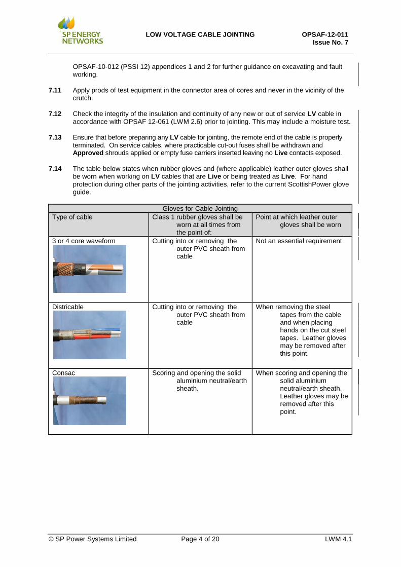
3 or 4 core waveform
Cutting into or removing the outer PVC sheath from cable
Not an essential requirement
Districable
Cutting into or removing the outer PVC sheath from cable
When removing the steel tapes from the cable and when placing hands on the cut steel tapes. Leather gloves may be removed after this point.
Consac
Scoring and opening the solid aluminium neutral/earth sheath.
When scoring and opening the solid aluminium neutral/earth sheath. Leather gloves may be removed after this point.

LOW VOLTAGE CABLE JOINTING
OPSAF-12-011
Issue No. 7
© SP Power Systems Limited Page 5 of 20 LWM 4.1
PILC cable (main or service) - not concentric
Scoring and opening the lead sheath
When scoring and opening the lead sheath. Leather gloves may be removed after this point.
Plastic service cable
Cutting into or removing the outer PVC sheath from cable
Not an essential requirement
PILC concentric cable (main or service)
Scoring and opening the lead sheath.
When scoring and opening the lead sheath. Leather gloves may be removed after this point.
8. PRELIMINARY STEPS
The following steps shall be carried out prior to Live LV jointing.
Step 1 Complete a Site Risk Assessment in accordance with the Health and Safety Handbook. Step 2 Consult appropriate cable records prior to the commencement of any excavation. Step 3 Use cable avoidance tool (CAT) to indicate position of buried cables before and during
excavation. Step 4 Use safe digging techniques to avoid inadvertent contact while carrying out any excavation. Step 5 Identify any cable on which work is to commence in accordance with the procedure specified in
OPSAF-10-012 (PSSI 12), Appendix 1. Step 6 Visually inspect the cable on which it is proposed to carry out work to ascertain its general
physical condition. In the event of any significant deficiency in the condition which could give rise to Danger, stop work immediately and do not attempt to work on the cable. Revise the Site Risk Assessment. Any ongoing work shall only take place by an appropriately Authorised Person in accordance with PSSI 12 Appendix 2.
Step 7 Assess the immediate surroundings of the cable to be worked on for possible Dangers, which
could arise from adjacent metal work e.g. exposed metal water pipes. Step 8 Screen or shroud all exposed metal work identified in Step 7 above with Approved insulating
material to avoid Danger.

LOW VOLTAGE CABLE JOINTING
OPSAF-12-011
Issue No. 7
© SP Power Systems Limited Page 6 of 20 LWM 4.1
9. PROCEDURE FOR ACCESSING, TESTING AND CUTTING DISTRIBUTOR MAINS AND SERVICE CABLES
The following cable types are in common use. Live jointing techniques shall be used at all times when working on LV cables.
9.1 Accessing the phase, neutral and earth conductors
(a) Waveform (3 or 4 core) Step 1 Remove outer PVC sheath using insulated ceramic stripping knife. Step 2 Remove the soft unvulcanised rubber, if present, in which the neutral/earth or earth wires are
embedded using an insulated Hepnyf. Step 3 Lift the neutral/earth or earth wires using an insulated core separator from the inner rubber
bedding. Step 4 Remove the inner unvulcanised rubber from the cores using an insulated Hepnyf.
(b) Districable Step 1 Remove the outer PVC sheath using insulated ceramic stripping knife. Step 2 Remove steel armour tapes as follows: - Fix a wire binder against the end of the PVC sheath at either end of the sheath cut. Cut the
tapes in the centre of the joint using an insulated stripping knife and tear off each side at the binder, nicking the tapes at the binders as necessary.
Step 3 Apply double wrap of PVC tape at the binders to prevent damage resulting from the sharp edges
of the steel tape. (c) PILC Cables
Note: Concentric PILC main and triple concentric service cables shall not be jointed Live. They may be
stripped down Live to a point where the lead sheath and the belting papers have been removed. If it is confirmed that the cable is a concentric PILC main or triple concentric service cable then it shall be Isolated. The cable can be temporarily re-energised to allow polarity/phase testing to be carried out only after all cores have been cut and insulated using Live working techniques. Single phase PILC concentric service cables may be jointed Live only if testing proves the outer strands/wires are the neutral conductor. If testing proves the outer strands/wires are a phase then the cable shall be Isolated.
Step 1 Remove outer hessian serving using an insulated ceramic stripping knife. Step 2 Strip the armours of the cable using a guarded saw, insulated junior hacksaw and/or tin-snips to
the dimensions given in the installation instructions. Step 3 Remove any inner hessian or fabric tapes then clean and degrease to expose the lead sheath Step 4 Complete armour / earth bonds Step 5 Connect a temporary continuity bond on to the lead sheath adjacent to armour bond(s). Step 6 Remove the lead sheath and belting papers using insulated Hepnyf to the point where the
neutral and phase cores are accessible.

LOW VOLTAGE CABLE JOINTING
OPSAF-12-011
Issue No. 7
© SP Power Systems Limited Page 7 of 20 LWM 4.1
(d) Consac Cable Consac cables shall not be worked on Live. Before work starts all reasonably practicable steps shall be taken to ensure cables are not Live. Although conductors are proved not Live, Live working techniques shall be used.
Step 1 Remove PVC sheath using an insulated ceramic stripping knife and clean and degrease the
aluminium sheath. Step 2 Strip the cable using the Approved Kennion Irvine Consac cable sheath cutting tool to the point
where the insulated phase cores are accessible. Step 3 Test the three conductors and neutral with an Approved test lamp for phase-to-earth and
phase-to-phase voltages. Step 4 Stop all work on the cable if it is found to be Live and refer to the supervisor. Do no further
work on the cable until it has been Isolated and proved to be not Live. After the cable has been Isolated, work may resume whilst continuing to use Live working techniques.
(e) Plastic Service Cables
Step 1 Remove outer PVC sheath and any plastic or fabric tapes over the earth, neutral or
neutral/earth wires using an insulated ceramic stripping knife. Step 2 Cut half of the earth, neutral or neutral/earth wires using a core guard and core cutters. Step 3 Unwind the wires and reconnect together using and extended brass tunnel connector. Step 4 Repeat for the other half of the remaining earth, neutral or neutral/earth wires. Step 5 Remove inner PVC sheath if present and any plastic or fabric fillers from between and
around the phase conductors using an insulated ceramic coring knife.
9.2 Testing Voltage Conditions
The following tests shall be carried out in accordance with OPSAF-12-003 (LWM 2.1) and OPSAF-12-061 (LWM 2.6). NOTE: When a cable is to be made Live for the first time by jointing, it shall be confirmed that the
appropriate checks such as insulation resistance and continuity tests have been completed and that the remote ends have been terminated in an Approved manner such that it is safe to energise. When the cable is being re-energised by jointing, then before re-making the cable Live, consider if further checks are required on the remote end(s) of the cable to ensure that it is safe to proceed.
When there is one Live cable involved in a cable jointing activity then the tests in the table below shall be completed using an Approved test lamp. Finally, conditions between core(s) prior to making connection shall be verified. If the results prove to be different from those expected, STOP and consult with a supervisor.
Test L1- E&N or N/E L2- E&N or N/E L3- E&N or N/E Neutral - Earth
Expected Result 230V 230V 230V 0V
Test L1- L2 L1- L3 L2- L3
Expected Result 400V 400V 400V When there are two or more Live cables to be jointed together then the tests above shall be carried out on each Live cable plus the additional tests below. Once the phasing tests on the cables have

LOW VOLTAGE CABLE JOINTING
OPSAF-12-011
Issue No. 7
© SP Power Systems Limited Page 8 of 20 LWM 4.1
been completed then all same-phase cores shall be marked with phasing tape prior to any connections being made. Finally, conditions between cores of different cables shall be verified as detailed in the table below prior to making connection.
Test L1- L1 L1- L2 L1- L3 L2- L2 L2- L3 L3- L3
Expected Result 0V 400V 400V 0V 400V 0V
9.3 Cutting Live LV Cables
Where a LV cable(s) is to be cut to carry out any of the jointing procedures then the following steps shall be carried out using Live jointing techniques. Step 1 Prepare the cables by accessing the conductors as in section 9.1 of this document. Step 2 Confirm the voltage conditions of the cable(s) by testing as described in section 9.2 using an
Approved test lamp, by puncturing the core insulation away from the crutch of the cable. The punctures shall be over-taped with PVC tape after testing.
Step 3 Insulate temporarily all exposed earth or neutral/earth conductors and exposed lead sheaths
with Approved screening material. Step 4 Lift the phase core to be cut using an insulated core separator. Protect the remaining cores from
inadvertent damage during the cutting process with the insulated core guard. Cut one phase at a time using insulated core cutters or insulated junior hacksaw and insulate the cores temporarily with insulated end caps.
Step 5 Remove temporary shrouding and cut the neutral or neutral/earth and then earth conductors only
after all phase conductors have been cut and insulated. Insulate the neutral temporarily with insulated end caps.
Step 6 If the cable has been cut to establish a Point of Isolation, apply a Caution Notice at a suitable
position.

LOW VOLTAGE CABLE JOINTING
OPSAF-12-011
Issue No. 7
© SP Power Systems Limited Page 9 of 20 LWM 4.1
10. PROCEDURE WL1.10 - MAKING STRAIGHT JOINTS OR LOOP JOINTS/TROUSER JOINTS (WAVEFORM, DISTRICABLE, PILC)
Step 1 Prepare the cables by accessing the conductors as in section 9.1 of this document. Step 2 Confirm the voltage conditions of the cable(s) by testing as described in section 9.2 using an
Approved test lamp, by puncturing the core insulation away from the crutch of the cable. The punctures shall be over-taped with PVC tape after testing.
Step 3 Refer to section 9.3 when cables are to be cut before jointing. Step 4 Make the permanent earth, neutral or neutral/earth conductor connection(s) in accordance with
the appropriate installation instruction. Step 5 Insulate temporarily all exposed earth, neutral or neutral/earth conductors and exposed lead
sheaths with Approved screening material. Step 6 In accordance with section 9.2, confirm with an Approved test lamp that the conductors to be
connected are of the same phase. Step 7 Working on one phase at a time set and cut cores at the connector position. Complete
connection and insulation of the phase conductors in accordance with the appropriate installation instructions.
Step 8 Remove the temporary Approved screening material from the earth, neutral or neutral/earth
conductor and lead sheath. Step 9 Complete the joint in accordance with the installation instruction.
11. PROCEDURE WL1.11 - MAKING BREECH JOINTS OR THREE LOOSE END JOINTS (WAVEFORM, DISTRICABLE, PILC)
Step 1 Prepare the cables by accessing the conductors as in section 9.1 of this document. Step 2 Confirm the voltage conditions of the cable(s) by testing as described in section 9.2 using an
Approved test lamp, by puncturing the core insulation away from the crutch of the cable. The punctures shall be over-taped with PVC tape after testing.
Step 3 When cables are to be cut prior to jointing refer to section 9.3. Step 4 Make the permanent Earth, Neutral or Neutral/Earth conductor connection(s) in accordance with
the appropriate installation instruction. Step 5 Insulate temporarily all exposed earth, neutral or neutral/earth conductors and exposed lead
sheaths with Approved screening material. Step 6 In accordance with section 9.2, and working on one phase at a time, confirm with an Approved
test lamp that the conductors to be connected are of the same phase, prior to connection. Step 7 Working on one phase at a time set and cut cores at the connector position. Complete
connection and insulation of the phase conductors in accordance with the appropriate installation instructions.
Step 8 Remove the temporary Approved screening material from the earth, neutral or neutral/earth
conductor and lead sheath. Step 9 Complete the joint in accordance with the appropriate installation instruction
LOW VOLTAGE CABLE JOINTING
OPSAF-12-011
Issue No. 7
© SP Power Systems Limited Page 10 of 20 LWM 4.1
12. PROCEDURE WL1.12 - MAKING SERVICE JOINTS
12.1 Service Joints on Waveform, Districable and PILC Cables using Insulated Insulation Piercing Connectors (IIPC)
For the sake of clarity the following procedure has been written for a single service cable. The procedure is also applicable to three phase or multiple service cables.
Step 1 Strip the service cable and terminate in cut-out in accordance with the installation instructions. Step 2 Strip the main cable in accordance with the appropriate installation instruction and section 9.1 of
this document. Step 3 Confirm the voltage conditions of the cable(s) by testing as described in section 9.2 using an
Approved test lamp, by puncturing the core insulation away from the crutch of the cable. The punctures shall be over-taped with PVC tape after testing.
Step 4 Strip the service cable at the joint end following the appropriate installation instruction and carry
out insulation resistance and continuity tests in accordance with OPSAF-12-061 (LWM 2.6). either, (a) Three core Waveform Cables Step 5 Make off the service cable neutral/earth conductor and cross bonding connections. Step 6 Screen, temporarily all exposed earth, neutral and neutral/earth conductors with Approved
screening material. Step 7 Working on one phase at a time, connect the service cable phase conductors to the phase
conductors of the main cable using an appropriate Approved mechanical connector. Step 8 Remove the temporary Approved screening material from the earth, neutral or neutral/earth
conductor and lead sheath. Step 9 Check the cut-out for incoming supply correct polarity, neutral and earth loop impedance and
phase rotation as applicable in accordance with OPSAF-12-061 (LWM 2.6).
Step 10 Complete the joint in accordance with appropriate installation instruction. or, (b) Four core Waveform Cables Step 5 Make off the service cable earth or neutral/earth conductor cross bonding connections. Step 6 Connect the Approved mechanical connector to the neutral core of the main and confirm
connection by using an Approved test lamp. Step 7 For Non-P.M.E. supplies connect the service cable earth and neutral conductors in accordance
with the appropriate installation instruction.
For P.M.E. supplies connect the service cable neutral/earth to neutral and earth cross bond in accordance with the appropriate installation instruction.
Step 8 Screen, temporarily all exposed earth, neutral and neutral/earth conductors with Approved
screening material. Step 9 Working on one phase at a time, connect the service cable phase conductors to the phase
conductors of the main cable using appropriate approved mechanical connector. Step 10 Remove the temporary Approved screening material from the earth, neutral or neutral/earth
conductor and lead sheath.

LOW VOLTAGE CABLE JOINTING
OPSAF-12-011
Issue No. 7
© SP Power Systems Limited Page 11 of 20 LWM 4.1
Step 11 Check the cut-out for incoming supply correct polarity, neutral and earth loop impedance and
phase rotation as applicable in accordance with OPSAF-12-061 (LWM 2.6). Step 12 Complete the joint in accordance with the appropriate installation instruction.
or, (c) Districable Step 5 Remove the lead covering from the neutral/earth conductor on the main cable.
Step 6 Make the service cable neutral/earth connection using the Approved mechanical connector prior to connection of phases. Carry out polarity tests to confirm contact.
Step 7 Screen temporarily all exposed earth, neutral and neutral/earth conductors and exposed lead
sheaths with Approved screening material. Step 8 Working on one phase at a time, connect the service cable phase conductors to the phase
conductors of the main cable using Approved mechanical connector. Step 9 Remove the temporary Approved screening material from the earth, neutral or neutral/earth
conductor and lead sheath. Step 10 Check the cut-out for incoming supply and correct polarity.
Step 11 Check the cut-out for incoming supply correct polarity, neutral and earth loop impedance and phase rotation as applicable in accordance with OPSAF-12-061 (LWM 2.6).
Step 12 Complete the joint in accordance with the appropriate installation instruction. or, (d) PILC Cables Step 5 Make the permanent earth bond on the lead sheaths. Step 6 Connect the Approved mechanical connector to the neutral core of the main and confirm
connection by using an Approved test lamp. Step 7 For Non-P.M.E. supplies connect the service cable earth and neutral conductors in accordance
with the appropriate installation instruction. For P.M.E. supplies connect the service cable neutral/earth to neutral and earth lead sheath
bond in accordance with the appropriate installation instruction. Step 8 Screen, temporarily all exposed earth, neutral and neutral/earth conductors and lead sheaths
with Approved screening material. Step 9 Working on one phase at a time, connect the service cable phase conductors to the phase
conductors of the main cable using Approved mechanical connector. Step 10 Remove the temporary Approved screening material from the earth, neutral or neutral/earth
conductor and lead sheath. Step 11 Check the cut-out for incoming supply and correct polarity. Step 12 Check the cut-out for incoming supply correct polarity, neutral and earth loop impedance and
phase rotation as applicable in accordance with OPSAF-12-061 (LWM 2.6). Step 13 Complete the joint in accordance with the appropriate installation instruction.

LOW VOLTAGE CABLE JOINTING
OPSAF-12-011
Issue No. 7
© SP Power Systems Limited Page 12 of 20 LWM 4.1
12.2 Service Cable to Service Cable Branch Joints using Mechanical Connectors
The following procedure has been written to allow a single phase service cable to be branched from a single or three phase service cable to give a supply to street furniture.
Step 1 Strip the new service cable end and terminate in cut-out in accordance with the appropriate installation instruction.
Step 2 Strip the through service cable in accordance with the appropriate installation instruction. and
section 9.1 of this document, to the point where the neutral and phase cores are accessible. Step 3 Confirm the voltage conditions of the cable(s) by testing as described in section 9.2 using an
Approved test lamp, by puncturing the core insulation away from the crutch of the cable. The punctures shall be over-taped with PVC tape after testing.
Step 4 Strip the new service cable at the joint end following the appropriate installation instruction and
carry out insulation resistance and continuity tests in accordance with OPSAF-12-061 (LWM 2.6)
Note: For PILC cables, make the permanent earth bond on the lead sheath. Step 5 Connect the earth and neutral or neutral/earth, conductors in accordance with the appropriate
installation instruction. Step 6 Screen, temporarily all exposed earth, neutral and neutral/earth conductors and lead sheaths
with Approved screening material. Step 7 Working on one phase at a time set and cut core at the connector position. Complete
connection and insulation of the phase conductors in accordance with the appropriate installation instructions.
Step 8 Remove the temporary Approved screening material from the earth, neutral or neutral/earth
conductor and lead sheath.
Step 9 Check the cut-out for incoming supply correct polarity, neutral and earth loop impedance and phase rotation as applicable in accordance with OPSAF-12-061 (LWM 2.6).
Step 10 Complete the joint in accordance with the appropriate installation instruction.

LOW VOLTAGE CABLE JOINTING
OPSAF-12-011
Issue No. 7
© SP Power Systems Limited Page 13 of 20 LWM 4.1
13. PROCEDURE WL1.13 MAKING SERVICE CABLE STRAIGHT JOINTS
Step 1 Ensure that before preparing a service cable for jointing, the remote end of the service is properly terminated and where practicable cut-out fuses are withdrawn leaving no Live contacts exposed.
Step 2 Prepare the cables by accessing the conductors as in section 9.1 of this document. Step 3 Confirm the voltage conditions of the cable(s) by testing as described in section 9.2 using an
Approved test lamp, by puncturing the core insulation away from the crutch of the cable. The punctures shall be over-taped with PVC tape after testing.
Step 4 Refer to section 9.3 when cables are to be cut prior to jointing. Step 5 Make the permanent earth, neutral or neutral/earth conductor connection(s) in accordance with
the appropriate Approved installation instruction. Step 6 Insulate temporarily all exposed earth, neutral or neutral/earth conductors and exposed lead
sheaths with Approved screening material. Step 7 Confirm with an Approved test lamp, prior to connection and working on one phase at a time,
the conductors to be connected are safe to energise. Step 8 Working on one phase at a time set and cut cores at the connector position. Complete
connection and insulation of the phase conductors in accordance with the appropriate installation instructions.
Step 9 Remove the temporary Approved screening material from the earth, neutral or neutral/earth
conductor and lead sheath.
Step 10 Check the cut-out for incoming supply correct polarity, neutral and earth loop impedance and phase rotation as applicable in accordance with OPSAF-12-061 (LWM 2.6).
Step 11 Complete the joint in accordance with the appropriate installation instruction.

LOW VOLTAGE CABLE JOINTING
OPSAF-12-011
Issue No. 7
© SP Power Systems Limited Page 14 of 20 LWM 4.1
14. PROCEDURE WL1.14 - MAKING POT ENDS (WAVEFORM, DISTRICABLE, CONCENTRIC, PILC OR SERVICE CABLES)
This procedure is applicable for permanent pot ends. All disconnections shall where reasonably practicable be cut outside customer’s boundary and as close to the main service joint as detailed in EPS-04-002. Disconnection sheet to be completed in accordance with local management procedure where required. Step 1 Prepare the cable by accessing conductors as section 9.1 of this document. Step 2 Confirm the voltage conditions of the cable(s) by testing as described in section 9.2 using an
Approved test lamp, by puncturing the core insulation away from the crutch of the cable. The punctures shall be over-taped with PVC tape after testing.
Step 3 Insulate temporarily all exposed earth, neutral or neutral/earth conductors and exposed lead
sheaths with Approved screening material. Step 4 Lift the phase core to be cut using an insulated core separator. Protect the remaining cores from
inadvertent damage during the cutting process with the insulated core guard. Cut one phase at a time and permanently insulate the cores following appropriate installation instruction.
Note: During the cutting process the not Live cores shall be insulated using Approved insulated end
caps. Step 5 Remove the temporary Approved screening material from the earth, neutral or neutral/earth
conductor and lead sheath.
Step 6 Cut the earth, neutral or neutral/earth conductors only after all phase conductors have been cut and insulated.
Step 7 Complete the joint in accordance with the appropriate installation instruction.
LOW VOLTAGE CABLE JOINTING
OPSAF-12-011
Issue No. 7
© SP Power Systems Limited Page 15 of 20 LWM 4.1
15. PROCEDURE WL1.19 MAKING, BREAKING DOWN AND RE-MAKING TEMPORARY JOINTS
This procedure refers to the joints described in NETOP-21-002.
NOTE: During fault location and repair processes it may be required to make off temporary joints. Temporary joints shall be protected in line with Local Network Operations Guidance Note(s).
There are four types of temporary joints approved for use. They are:
Temporary Open & Test,
Temporary Cut & Test,
Temporary Pot End
Temporary Strap-Over
15.1 Making Temporary Joints
15.1.1 Making Temporary Open & Test
This is where a cable needs to be opened and tested to establish the fault conditions/direction.
Step 1 Prepare the cables by accessing the conductors as in section 9.1 of this document. Step 2 Confirm the voltage conditions of the cable(s) by testing as described in section 9.2 using an
Approved test lamp, by puncturing the core insulation away from the crutch of the cable. The punctures shall be over-taped with PVC tape after testing.
NOTE: For PILC Cables; Make the permanent earth continuity connection between the lead sheaths
and remove temporary continuity bond.
Step 3 Complete temporary Open & Test in accordance with Local Network Operations Guidance Note(s)
15.1.2 Making Temporary Cut & Test
This is where a cable needs to be opened, cut and tested to establish the fault conditions/direction. The neutral shall be left continuous throughout this procedure. Step 1 Prepare the cables by accessing the conductors as in section 9.1 of this document.
Step 2 Confirm the voltage conditions of the cable(s) by testing as described in section 9.2 using an
Approved test lamp, by puncturing the core insulation away from the crutch of the cable. The punctures shall be over-taped with PVC tape after testing.
Step 3 Insulate temporarily all exposed earth or neutral/earth conductors and exposed lead sheaths with Approved screening material.
Step 4 Lift the phase core to be cut using an insulated core separator. Protect the remaining cores from inadvertent damage during the cutting process with the insulated core guard. Cut one phase at a time using insulated core cutters or insulated junior hacksaw and insulate the cores temporarily with insulated end caps.
NOTE: For fault location only the appropriate number of cores should be cut. The neutral should be left continuous and earth continuity shall be maintained. For PILC cables; make the permanent earth continuity connection between the lead sheaths and remove temporary continuity bond.
Step 5 Complete temporary Cut & Test in accordance with Local Network Operations Guidance Note(s)
LOW VOLTAGE CABLE JOINTING
OPSAF-12-011
Issue No. 7
© SP Power Systems Limited Page 16 of 20 LWM 4.1
15.1.3 Making Temporary Pot End
This is where a cable needs to be pot ended during fault location/repair process, where it has been established that all phase cores, neutral, neutral/earth or earth cores need to be cut. Step 1 Prepare the cables by accessing the conductors as in section 9.1 of this document. Step 2 Confirm the voltage conditions of the cable(s) by testing as described in section 9.2 using an
Approved test lamp, by puncturing the core insulation away from the crutch of the cable. The punctures shall be over-taped with PVC tape after testing.
Step 3 Insulate temporarily all exposed earth or neutral/earth conductor and exposed lead sheaths with
Approved screening material. Step 4 Lift the phase core to be cut using an insulated core separator. Protect the remaining cores from
inadvertent damage during the cutting process with the insulated core guard. Cut one phase at a time using insulated core cutters or insulated junior hacksaw and insulate the cores temporarily with insulated end caps.
Step 5 Remove temporary shrouding and cut the neutral or neutral/earth and then earth conductors only
after all phase conductors have been cut and insulated. Insulate the neutral temporarily with insulated end caps.
Step 6 Complete the temporary pot end in accordance with Local Network Operations Guidance
Note(s).
15.1.4 Making Temporary Strap-Over
This is where a cable needs to be opened, tested and a phase core cut and strapped across onto another healthy phase core to allow a temporary supply to be given while fault location/work is still in progress. This process shall only be done when a backfeed is not available and carried out between the point of fault and pot end location. Step 1 Prepare the cables by accessing the conductors as in section 9.1 of this document.
Step 2 Confirm the voltage conditions of the cable(s) by testing as described in section 9.2 using an
Approved test lamp, by puncturing the core insulation away from the crutch of the cable. The punctures shall be over-taped with PVC tape after testing.
Step 3 Insulated temporarily all exposed earth or neutral/earth conductors and exposed lead sheaths
with Approved screening material.
Step 4 Lift the not Live phase core to be cut using an insulated core separator. Protect the remaining cores from inadvertent damage during the cutting process with the insulated core guard.
Step 5 Cut the not Live phase core and insulate the source of supply side end with insulated end caps.
Step 6 Connect the other end on to a healthy phase core with an approved branch connector and insulate in accordance with the appropriate installation instruction.
Step 7 Complete the temporary pot end in accordance with Local Network Operations Guidance Note(s).
LOW VOLTAGE CABLE JOINTING
OPSAF-12-011
Issue No. 7
© SP Power Systems Limited Page 17 of 20 LWM 4.1
15.2 Making Temporary Joints Permanent
Note: Temporary protection used shall be removed in line with Local Network Operations Guidance. The following procedures are to be followed to complete the joint to a permanent state.
15.2.1 Remake Open & Test to be filled with Permanent Resin
(a) Waveform (3 or 4 core) or Districable
Step 1 Abrade outer sheath, fit joint shell and fill with permanent resin (b) PILC Cables
Step 1 Degrease lead sheath and apply moisture seals.
Step 2 Fit joint shell and fill with permanent resin. (c) Consac Cable
Step 1 Degrease aluminium sheath.
Step 2 Abrade outer sheath, apply moisture seals, fit joint shell and fill with permanent resin.
15.2.2 Remake Cut & Test to be filled with Permanent Resin
Step 1 Confirm the voltage conditions of the cable(s) by testing as described in section 9.2 using an Approved test lamp, by puncturing the core insulation away from the crutch of the cable. The punctures shall be over-taped with PVC tape after testing.
Step 2 Insulate temporarily all exposed earth, neutral or neutral/earth conductors and exposed lead sheaths with Approved screening material.
Step 3 Confirm with an Approved test lamp, prior to connection and working on one phase at a time, the conductors to be connected are of the same phase.
Step 4 Working on one phase at a time set cores at the connector position. Complete connection and
insulation of the phase conductors in accordance with the appropriate installation instructions.
Step 5 Remove the temporary Approved screening material from the earth, neutral or neutral/earth conductor and lead sheath.
Step 6 For PILC cables re-torque the existing worm drive clips of the permanent earth continuity
connection.
Step 7 Complete the joint in accordance with the approved installation instruction.
15.2.3 Remake Pot End to be filled with Permanent Resin
Step 1 For PILC cables re-torque the existing earth bond connections.
Step 2 Complete the joint in accordance with the approved installation instruction.

LOW VOLTAGE CABLE JOINTING
OPSAF-12-011
Issue No. 7
© SP Power Systems Limited Page 18 of 20 LWM 4.1
15.2.4 Remake Strap-Over to be filled with Permanent Resin
Note: This procedure shall be done not Live
Step 1 Insulate temporarily all exposed earth or neutral/earth conductors and exposed lead sheaths with Approved screening material.
Step 2 Remove Approved branch connector and insulate the uncut phase conductor with CR sheeting, and the cut phase core with an Approved insulated end cap.
Step 3 Set core at the connector position. Complete connection and insulation of the phase conductor in accordance with the appropriate installation instructions.
Step 4 Remove all Approved screening material
Step 5 For PILC cables re-torque the existing worm drive clips of the permanent earth continuity connection.
Step 6 Complete the joint in accordance with the Approved installation instruction.
16. PROCEDURE FOR REMOVAL OF RIGID DUCTING FROM AROUND MAIN OR SERVICE CABLE
Note: In addition to carrying out an onsite risk assessment, a number of additional risks / hazards may be present when removing ducting. The following list is known hazards that have been identified when carrying out this procedure.
Risk of explosion from faulty live cable within duct.
Signs of distress i.e. smoke, discolouration or smell of carbon.
Opening of incorrect ducts and subsequent damage to other utilities.
The possible presence of potentially explosive gas trapped within the duct. For this reason no naked flames or smoking are permitted while undertaking this work.
Contaminated / foul water within the duct.
Excessive water on long ducted runs.
Accessibility issues – close proximity of other utilities or multiple duct runs.
Awareness of other utilities high pressure gas or water systems. This list is not exhaustive. If any of the above are detected seek assistance before proceeding.
16.1 REMOVAL OF RIGID DUCTING
Step 1 Create an inspection window at the top of the duct by using an Approved insulated Hepnyf to make two parallel cuts along the length of the duct for a distance of 150mm at the centre point of the joint position.
Step 2 Using the Approved insulated Hepnyf make a circumferential cut to join the two parallel cuts and remove the section of ducting exposing the window.
Step 3 Identify the location of the cable within the ducting. Manipulate the cable to ensure it is situated at the bottom of the duct before proceeding.
Step 4 Using the Approved insulated Hepnyf, make a further two parallel cuts approximately half-way down each side of the duct to the required length for the appropriate joint type.
Step 5 Using the Approved insulated Hepnyf make a circumferential cut to join the two parallel cuts and remove the top section of ducting.
Step 6 Lift, and support the cable from the bottom of the duct.

LOW VOLTAGE CABLE JOINTING
OPSAF-12-011
Issue No. 7
© SP Power Systems Limited Page 19 of 20 LWM 4.1
Step 7 Protect the cable utilising the cut section of duct or neoprene sheeting etc. Use either the
Approved insulated Hepnyf or insulated junior hacksaw to remove the lower section of the duct.
16.2 REMOVAL OF CLASS 2, CIRCULAR SECTION EXTRUDED PLASTIC DUCTS
Approved tools required to remove Class 2 circular section ducting
Depth saw General purpose saw Ball pein hammer
Step 1 Due to the variance of the thickness of the duct an initial depth of 3mm shall be applied to the depth saw blade.
Step 2 Make two parallel cuts 100mm apart (picture 1). Make a further two parallel cuts perpendicular to the original cuts as per (picture 2) to form an inspection window at centre of jointing position.
Picture 1 Picture 2
Step 3 With a firm strike of the hammer remove the inspection window to expose the cable within the duct. If the inspection window fails to collapse then re adjust the depth of the initial cuts by 1mm increments until the window can be opened. (Picture 3)
Step 4 Ascertain the thickness of the ducting and set the depth saw accordingly.
Step 5 Identify the location of the cable within the ducting before proceeding. (picture 3)
Picture 3
Step 6 Make two circumferential cuts in the duct at the required length for the appropriate joint type using the guarded saw. (Picture 4)

LOW VOLTAGE CABLE JOINTING
OPSAF-12-011
Issue No. 7
© SP Power Systems Limited Page 20 of 20 LWM 4.1
Picture 4
Step 7 Manipulate the cut section until it becomes free from the main length of the duct (picture 5)
Picture 5
Step 8 Move the cut section to one side and insert a guiderail (length of wood, earth spikes, cable guard or similar). Cut along the duct ensuring the guiderail is between the saw and the cable (pictures 6 and 7)
Picture 6 Picture 7
Step 9 Remove the cut section of duct and the guiderail. Inspect the cable ensuring no damage has occurred (picture 8 and 9)
Picture 8 Picture 9