lush 101 manual
DESCRIPTION
la la la cool faceTRANSCRIPT
User Manual
Multitimbral Polyphonic Synthesizer
1
Overview
Overview
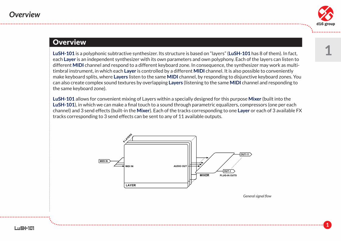
LuSH-101 is a polyphonic subtractive synthesizer. Its structure is based on “layers” (LuSH-101 has 8 of them). In fact, each Layer is an independent synthesizer with its own parameters and own polyphony. Each of the layers can listen to different MIDI channel and respond to a different keyboard zone. In consequence, the synthesizer may work as multi-timbral instrument, in which each Layer is controlled by a different MIDI channel. It is also possible to conveniently make keyboard splits, where Layers listen to the same MIDI channel, by responding to disjunctive keyboard zones. You can also create complex sound textures by overlapping Layers (listening to the same MIDI channel and responding to the same keyboard zone).
LuSH-101 allows for convenient mixing of Layers within a specially designed for this purpose Mixer (built into the LuSH-101), in which we can make a final touch to a sound through parametric equalizers, compressors (one per each channel) and 3 send effects (built-in the Mixer). Each of the tracks corresponding to one Layer or each of 3 available FX tracks corresponding to 3 send effects can be sent to any of 11 available outputs.
1
General signal flow
2
1
Overview
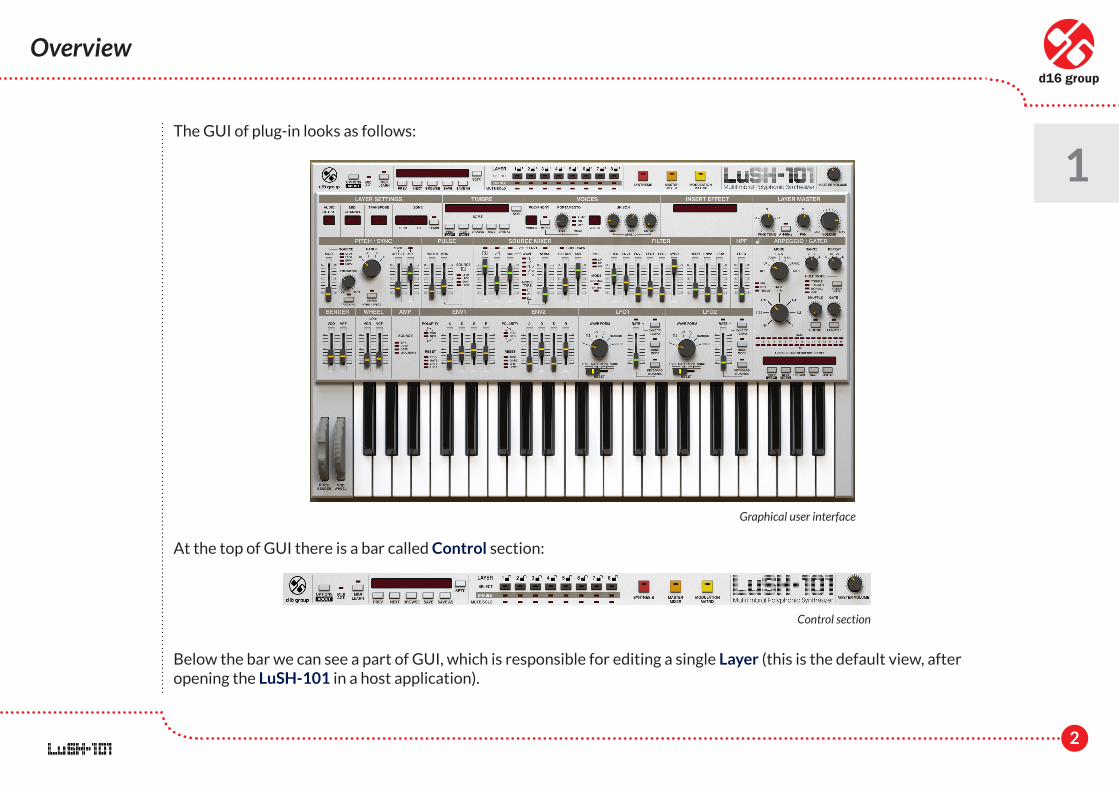
The GUI of plug-in looks as follows:
At the top of GUI there is a bar called Control section:
Below the bar we can see a part of GUI, which is responsible for editing a single Layer (this is the default view, after opening the LuSH-101 in a host application).
Graphical user interface
Control section
3
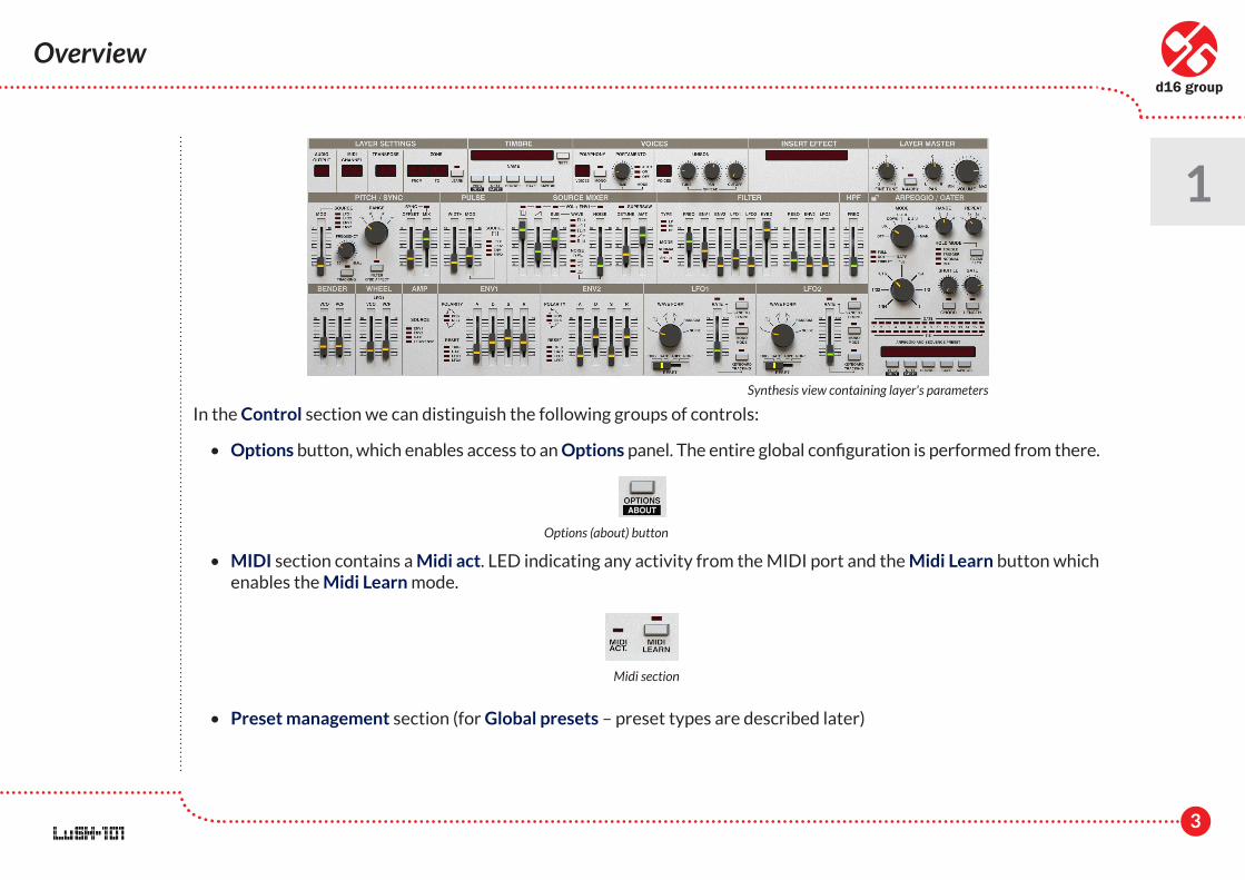
In the Control section we can distinguish the following groups of controls:
• Options button, which enables access to an Options panel. The entire global configuration is performed from there.
• MIDI section contains a Midi act. LED indicating any activity from the MIDI port and the Midi Learn button which enables the Midi Learn mode.
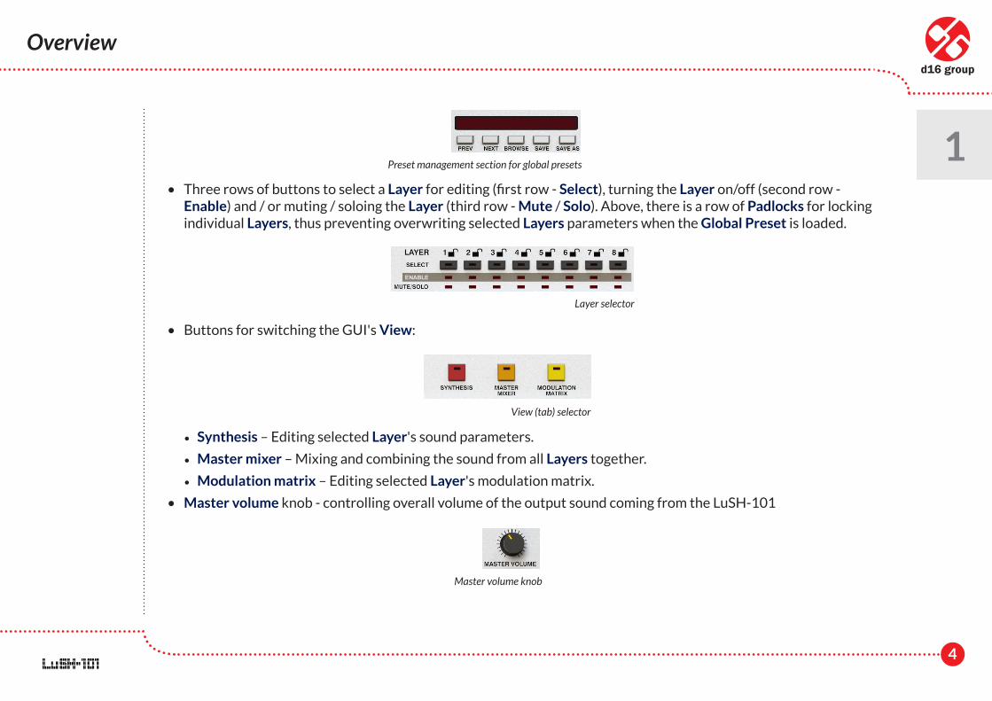
• Preset management section (for Global presets – preset types are described later)
1
Overview
Synthesis view containing layer's parameters
Options (about) button
Midi section
4
1
Overview
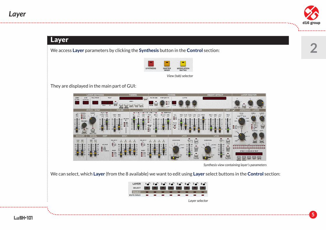
• Three rows of buttons to select a Layer for editing (first row - Select), turning the Layer on/off (second row - Enable) and / or muting / soloing the Layer (third row - Mute / Solo). Above, there is a row of Padlocks for locking individual Layers, thus preventing overwriting selected Layers parameters when the Global Preset is loaded.
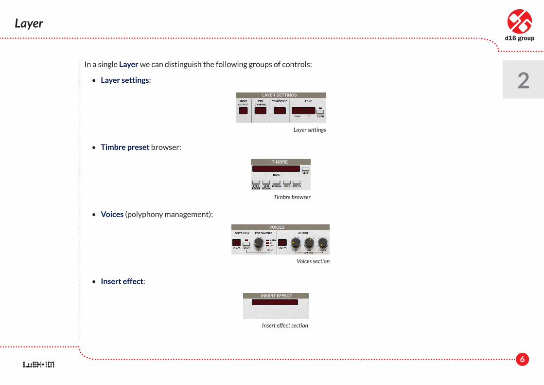
• Buttons for switching the GUI's View:
• Synthesis – Editing selected Layer's sound parameters.
• Master mixer – Mixing and combining the sound from all Layers together.
• Modulation matrix – Editing selected Layer's modulation matrix.
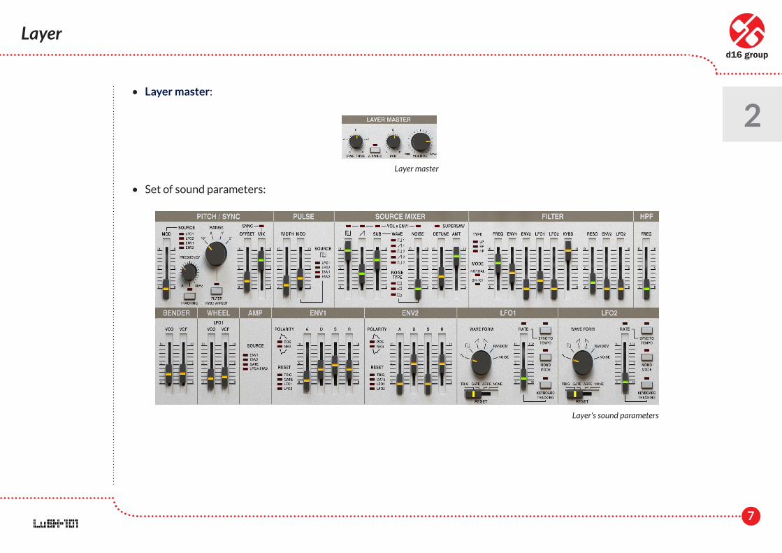
• Master volume knob - controlling overall volume of the output sound coming from the LuSH-101
Preset management section for global presets
Layer selector
View (tab) selector
Master volume knob
5
2
Layer
Layer
We access Layer parameters by clicking the Synthesis button in the Control section:
They are displayed in the main part of GUI:
We can select, which Layer (from the 8 available) we want to edit using Layer select buttons in the Control section:
View (tab) selector
Synthesis view containing layer's parameters
Layer selector
6
2
Layer
In a single Layer we can distinguish the following groups of controls:
• Layer settings:
• Timbre preset browser:
• Voices (polyphony management):
• Insert effect:
Layer settings
Timbre browser
Voices section
Insert effect section
7
2
Layer
• Layer master:
• Set of sound parameters:
Layer master
Layer's sound parameters
8
2
Layer • Layer settings
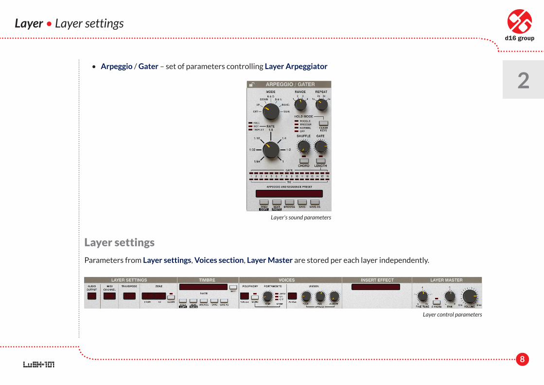
• Arpeggio / Gater – set of parameters controlling Layer Arpeggiator
Layer settings
Parameters from Layer settings, Voices section, Layer Master are stored per each layer independently.
Layer's sound parameters
Layer control parameters
9
2
Layer • Layer settings
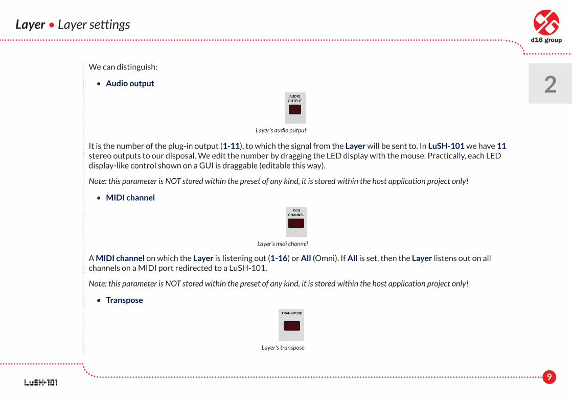
We can distinguish:
• Audio output
It is the number of the plug-in output (1-11), to which the signal from the Layer will be sent to. In LuSH-101 we have 11 stereo outputs to our disposal. We edit the number by dragging the LED display with the mouse. Practically, each LED display-like control shown on a GUI is draggable (editable this way).
Note: this parameter is NOT stored within the preset of any kind, it is stored within the host application project only!
• MIDI channel
A MIDI channel on which the Layer is listening out (1-16) or All (Omni). If All is set, then the Layer listens out on all channels on a MIDI port redirected to a LuSH-101.
Note: this parameter is NOT stored within the preset of any kind, it is stored within the host application project only!
• Transpose
Layer's audio output
Layer's midi channel
Layer's transpose
10
2
Layer • Layer settings
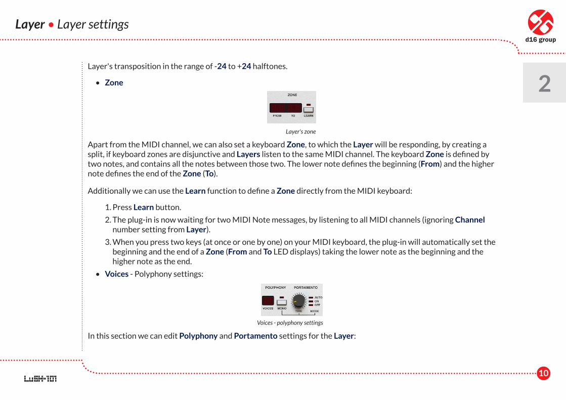
Layer's transposition in the range of -24 to +24 halftones.
• Zone
Apart from the MIDI channel, we can also set a keyboard Zone, to which the Layer will be responding, by creating a split, if keyboard zones are disjunctive and Layers listen to the same MIDI channel. The keyboard Zone is defined by two notes, and contains all the notes between those two. The lower note defines the beginning (From) and the higher note defines the end of the Zone (To).
Additionally we can use the Learn function to define a Zone directly from the MIDI keyboard:
1. Press Learn button.
2. The plug-in is now waiting for two MIDI Note messages, by listening to all MIDI channels (ignoring Channel number setting from Layer).
3. When you press two keys (at once or one by one) on your MIDI keyboard, the plug-in will automatically set the beginning and the end of a Zone (From and To LED displays) taking the lower note as the beginning and the higher note as the end.
• Voices - Polyphony settings:
In this section we can edit Polyphony and Portamento settings for the Layer:
Layer's zone
Voices - polyphony settings
11
Layer • Layer settings
2 • Voices – It is the total number of voices of Polyphony for Layer (up to 32 voices). If the number of voices is
equal to 1 then implicitly the Mono mode is set and other controls in this section start to work.
• Mono – This button turns on/off the Mono mode. If the number of voices of Polyphony is greater than 1, then we may use this switch to overturn the Mono mode on. In this situation the Polyphony is automatically reduced to one voice.
• Mode – This controls the Portamento mode and works only in the Mono mode and it has three values:
– Off – Portamento is off.
– On – Portamento is always on (for overlapping and non-overlapping MIDI notes).
– Auto – Portamento works only for overlapping MIDI notes.
• Time – It is the time of smooth pitch transition between two successively incoming notes.
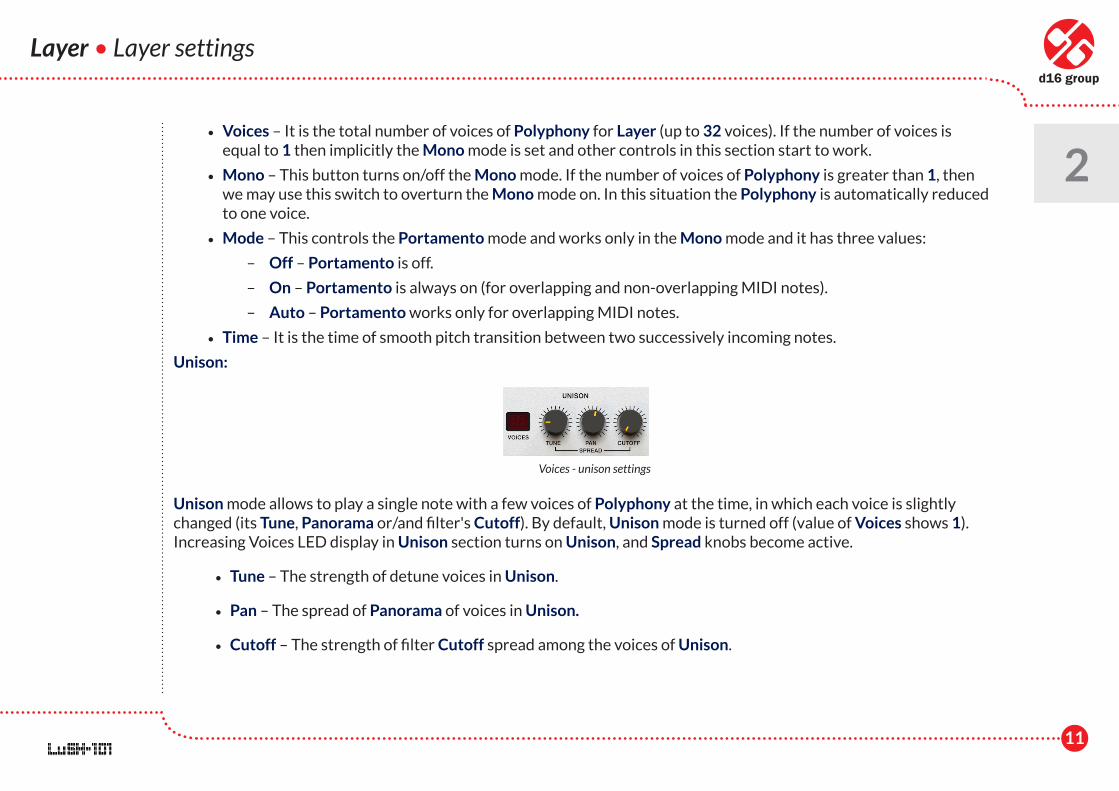
Unison:
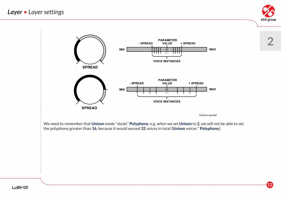
Unison mode allows to play a single note with a few voices of Polyphony at the time, in which each voice is slightly changed (its Tune, Panorama or/and filter's Cutoff). By default, Unison mode is turned off (value of Voices shows 1). Increasing Voices LED display in Unison section turns on Unison, and Spread knobs become active.
• Tune – The strength of detune voices in Unison.
• Pan – The spread of Panorama of voices in Unison.
• Cutoff – The strength of filter Cutoff spread among the voices of Unison.
Voices - unison settings
12
Layer • Layer settings
2
We need to remember that Unison mode “steals” Polyphony, e.g. when we set Unison to 2, we will not be able to set the polyphony greater than 16, because it would exceed 32 voices in total (Unison voices * Polyphony).
Unison spread
13
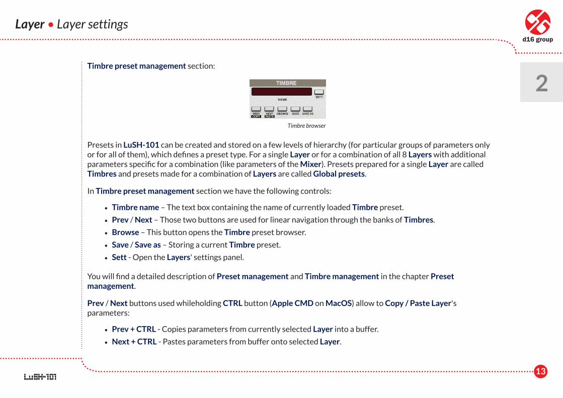
Timbre preset management section:
Presets in LuSH-101 can be created and stored on a few levels of hierarchy (for particular groups of parameters only or for all of them), which defines a preset type. For a single Layer or for a combination of all 8 Layers with additional parameters specific for a combination (like parameters of the Mixer). Presets prepared for a single Layer are called Timbres and presets made for a combination of Layers are called Global presets.
In Timbre preset management section we have the following controls:
• Timbre name – The text box containing the name of currently loaded Timbre preset.
• Prev / Next – Those two buttons are used for linear navigation through the banks of Timbres.
• Browse – This button opens the Timbre preset browser.
• Save / Save as – Storing a current Timbre preset.
• Sett - Open the Layers' settings panel.
You will find a detailed description of Preset management and Timbre management in the chapter Preset management.
Prev / Next buttons used whileholding CTRL button (Apple CMD on MacOS) allow to Copy / Paste Layer's parameters:
• Prev + CTRL - Copies parameters from currently selected Layer into a buffer.
• Next + CTRL - Pastes parameters from buffer onto selected Layer.
Layer • Layer settings
2
Timbre browser
14
Layer • Synthesis
2Synthesis
LuSH-101 is a subtractive synthesizer and the control of the signal flow used here does not differ substantially from most of compact hardware or software synthesizers on the market. It encompasses all the elements and components widely used in modern synthesizers.
Oscillators - VCO
LuSH-101 has four oscillators:
• Square with adjustable pulse width and HardSync option,
• Sawtooth with HardSync and SuperSaw options, Note: Supersaw oscillator operates on mixing few sawtooth waveforms, each slightly detuned.
• Suboscillator with 5 different waveforms to select from:
• Square with 50 / 50 pulse width, one octave below base frequency,
• Sawtooth, one octave below base frequency,
• Square with 50 / 50 pulse width, two octaves below base frequency,
• Sawtooth, two octaves below base frequency,
• Square with 25 / 75 pulse width, two octaves below base frequency,
• Noise generator with three different colors to select from:
• White,
• Pink,
• Brown.
15
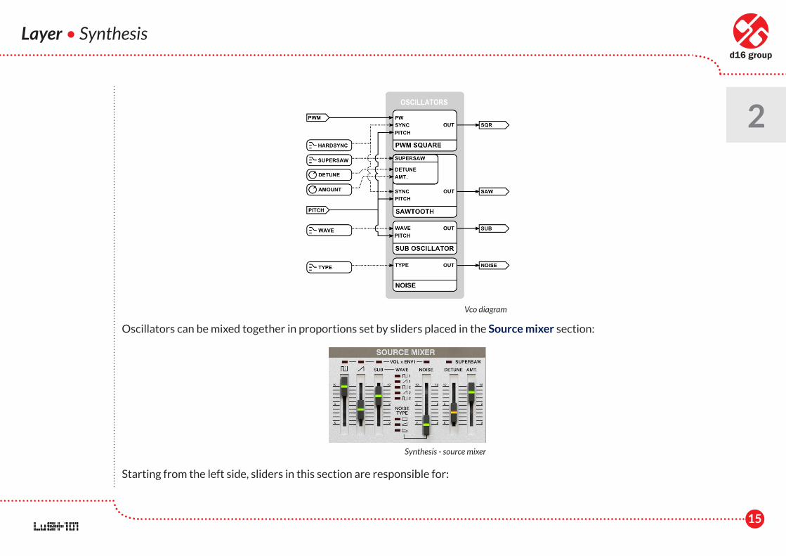
Oscillators can be mixed together in proportions set by sliders placed in the Source mixer section:
Starting from the left side, sliders in this section are responsible for:
Layer • Synthesis
2
Vco diagram
Synthesis - source mixer
16
Layer • Synthesis
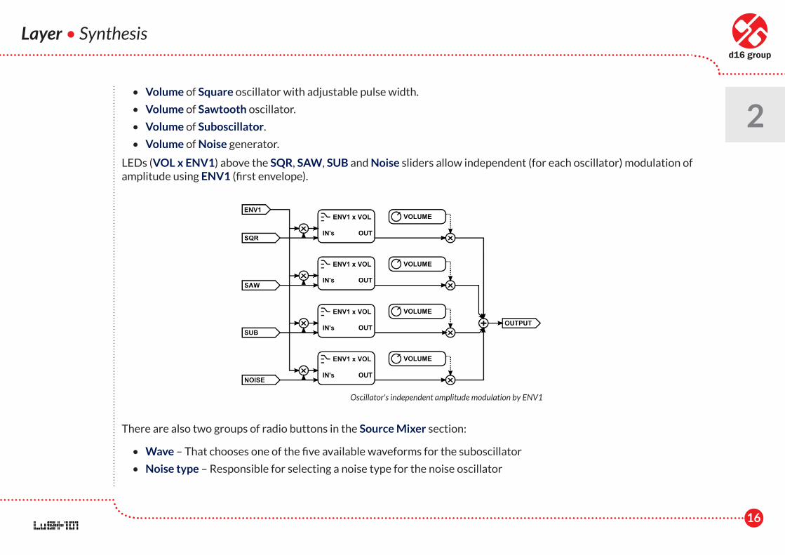
2 • Volume of Square oscillator with adjustable pulse width.
• Volume of Sawtooth oscillator.
• Volume of Suboscillator.
• Volume of Noise generator.
LEDs (VOL x ENV1) above the SQR, SAW, SUB and Noise sliders allow independent (for each oscillator) modulation of amplitude using ENV1 (first envelope).
There are also two groups of radio buttons in the Source Mixer section:
• Wave – That chooses one of the five available waveforms for the suboscillator
• Noise type – Responsible for selecting a noise type for the noise oscillator
Oscillator's independent amplitude modulation by ENV1
17
HardSync
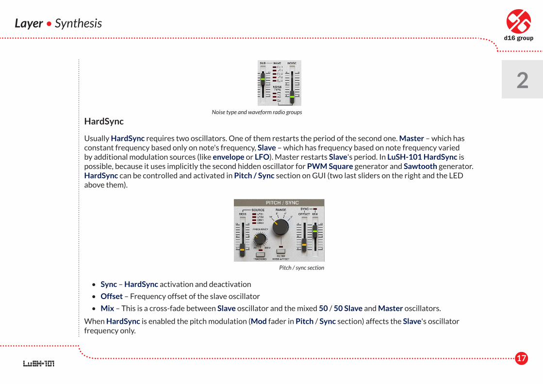
Usually HardSync requires two oscillators. One of them restarts the period of the second one. Master – which has constant frequency based only on note's frequency, Slave – which has frequency based on note frequency varied by additional modulation sources (like envelope or LFO). Master restarts Slave's period. In LuSH-101 HardSync is possible, because it uses implicitly the second hidden oscillator for PWM Square generator and Sawtooth generator. HardSync can be controlled and activated in Pitch / Sync section on GUI (two last sliders on the right and the LED above them).
• Sync – HardSync activation and deactivation
• Offset – Frequency offset of the slave oscillator
• Mix – This is a cross-fade between Slave oscillator and the mixed 50 / 50 Slave and Master oscillators.
When HardSync is enabled the pitch modulation (Mod fader in Pitch / Sync section) affects the Slave's oscillator frequency only.
Layer • Synthesis
2Noise type and waveform radio groups
Pitch / sync section

18
Layer • Synthesis
2Supersaw
Two last sliders in the Source Mixer section and the LED above them are responsible for controlling the SuperSaw mode for the Sawtooth oscillator.
Supersaw LED activates and deactivates that mode, and parameters:
• Amt. - Amount, the effect strength, the bigger the value is, the more saw oscillators are added.
• Detune – This is the detune value between additional saw oscillators.
Note: Please note that SuperSaw and HardSync cannot work at once. If you turn on HardSync mode, SuperSaw will be automatically disabled.
Supersaw works alternatively to Sawtooth oscillator, therefore, the amplitude of Supersaw is controlled by Sawtooth's volume fader in the Source Mixer section.
Supersaw parameters
Synthesis - source mixer
19
Layer • Synthesis
2Pulse Width Modulation – PWM
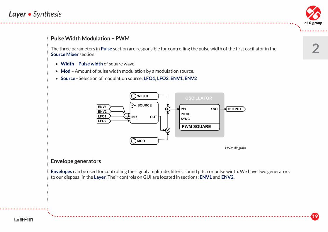
The three parameters in Pulse section are responsible for controlling the pulse width of the first oscillator in the Source Mixer section:
• Width – Pulse width of square wave.
• Mod – Amount of pulse width modulation by a modulation source.
• Source - Selection of modulation source: LFO1, LFO2, ENV1, ENV2
Envelope generators
Envelopes can be used for controlling the signal amplitude, filters, sound pitch or pulse width. We have two generators to our disposal in the Layer. Their controls on GUI are located in sections: ENV1 and ENV2.
PWM diagram
20
Layer • Synthesis
2
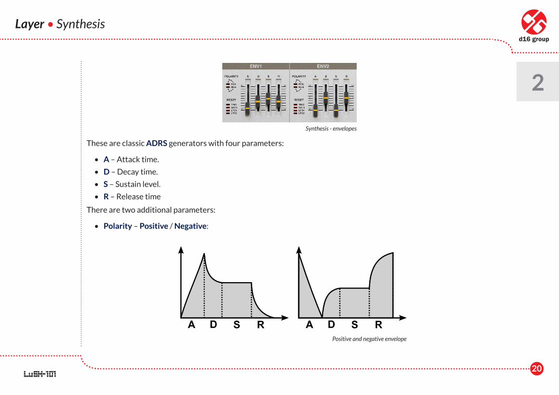
These are classic ADRS generators with four parameters:
• A – Attack time.
• D – Decay time.
• S – Sustain level.
• R – Release time
There are two additional parameters:
• Polarity – Positive / Negative:
Synthesis - envelopes
Positive and negative envelope
21
Layer • Synthesis
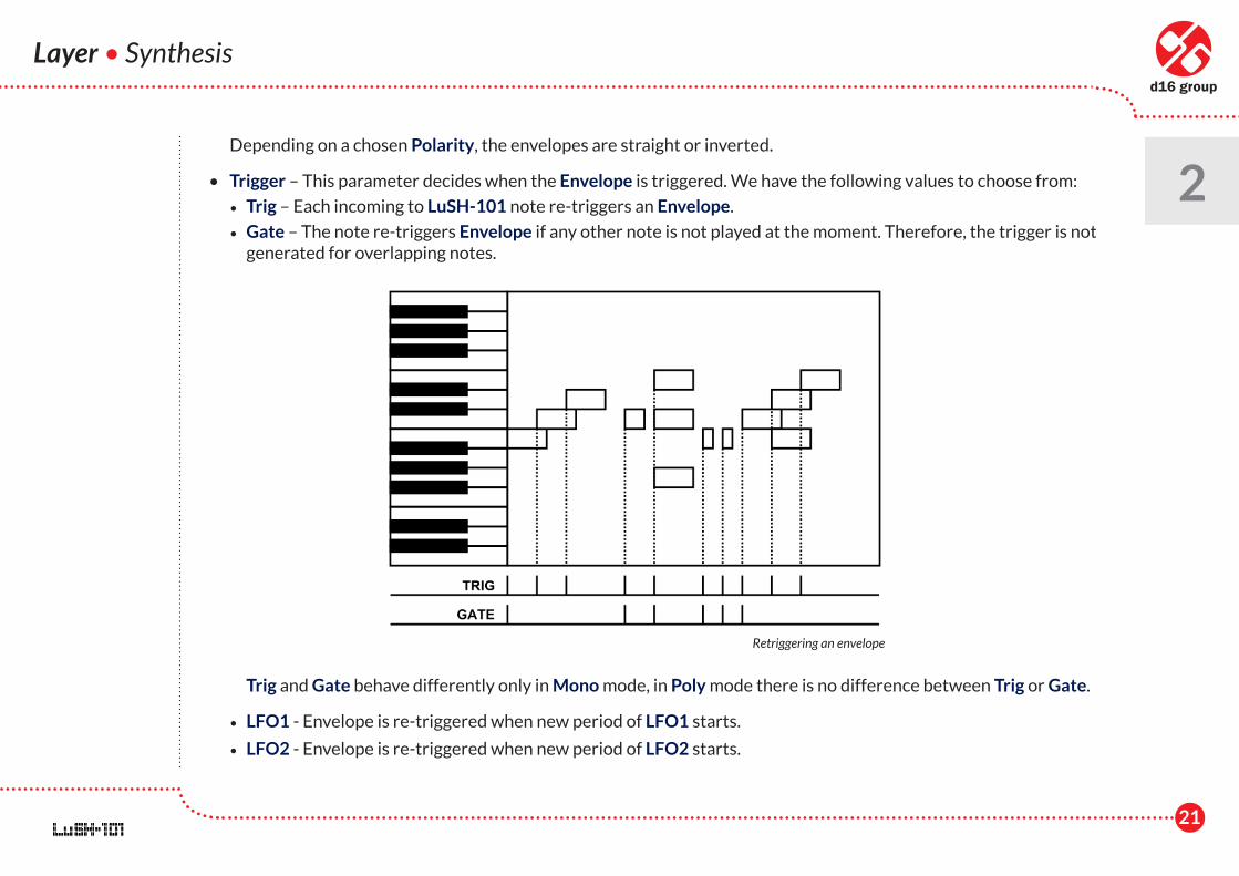
2 Depending on a chosen Polarity, the envelopes are straight or inverted.
• Trigger – This parameter decides when the Envelope is triggered. We have the following values to choose from:
• Trig – Each incoming to LuSH-101 note re-triggers an Envelope.
• Gate – The note re-triggers Envelope if any other note is not played at the moment. Therefore, the trigger is not generated for overlapping notes.
Trig and Gate behave differently only in Mono mode, in Poly mode there is no difference between Trig or Gate.
• LFO1 - Envelope is re-triggered when new period of LFO1 starts.
• LFO2 - Envelope is re-triggered when new period of LFO2 starts.
Retriggering an envelope
22
Layer • Synthesis
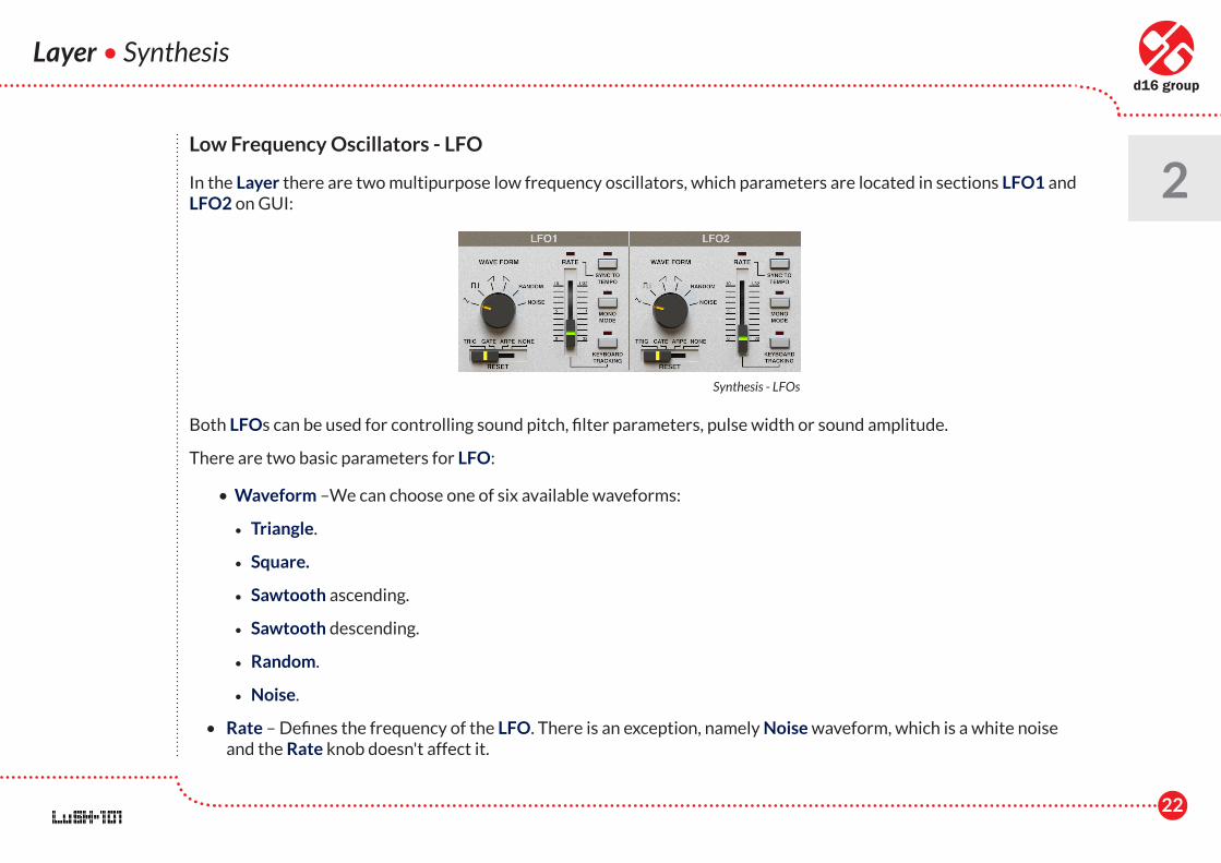
2Low Frequency Oscillators - LFO
In the Layer there are two multipurpose low frequency oscillators, which parameters are located in sections LFO1 and LFO2 on GUI:
Both LFOs can be used for controlling sound pitch, filter parameters, pulse width or sound amplitude.
There are two basic parameters for LFO:
• Waveform –We can choose one of six available waveforms:
• Triangle.
• Square.
• Sawtooth ascending.
• Sawtooth descending.
• Random.
• Noise.
• Rate – Defines the frequency of the LFO. There is an exception, namely Noise waveform, which is a white noise and the Rate knob doesn't affect it.
Synthesis - LFOs
23
Layer • Synthesis
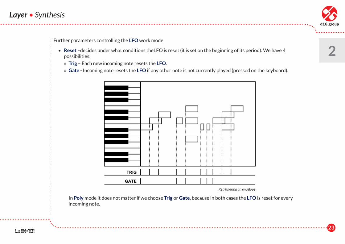
2Further parameters controlling the LFO work mode:
• Reset –decides under what conditions theLFO is reset (it is set on the beginning of its period). We have 4 possibilities:
• Trig – Each new incoming note resets the LFO.
• Gate - Incoming note resets the LFO if any other note is not currently played (pressed on the keyboard).
In Poly mode it does not matter if we choose Trig or Gate, because in both cases the LFO is reset for every incoming note.
Retriggering an envelope
24
Layer • Synthesis
2 • Arpe - This works only when the Arpeggiator is active. The LFO is reset when the Arpeggiator starts generating
a sequence, i.e. when we release all the keys on the MIDI keyboard and press them (or one of them) again.
• None – the LFO is never reset.
• Sync to tempo – This switch is responsible for the LFO’s synchronization with the tempo. By default, the LFO is internally timed (Sync if off). When we turn on Sync, the frequency of the LFO will depend on the tempo set in a host application and the Rate will be a discrete parameter which defines a time scale (as notation values): 32, 16, 8, 4, 2, 1 bars, 1/2 , 1/4 , 1/8 , 1/16 and 1/32
• Keyboard Tracking – When turned on, the frequency of the note affects the LFO frequency. With this feature we can achieve a simple FM synthesis (modulating a frequency of VCO with LFO).
• Mono mode – Turned off by default. In Poly mode with Mono switched on, all voices in the Layer have synchronized LFOs together in a phase, giving an impression of a single LFO controlling all voices at once.
Filters
LuSH-101 has two serially connected filters.
• The second one is a multi-mode resonant filter (Lo-pass, Band-pass and Hi-pass)
• The first one is a Hi-pass filter with a characteristic RC analogue filter.
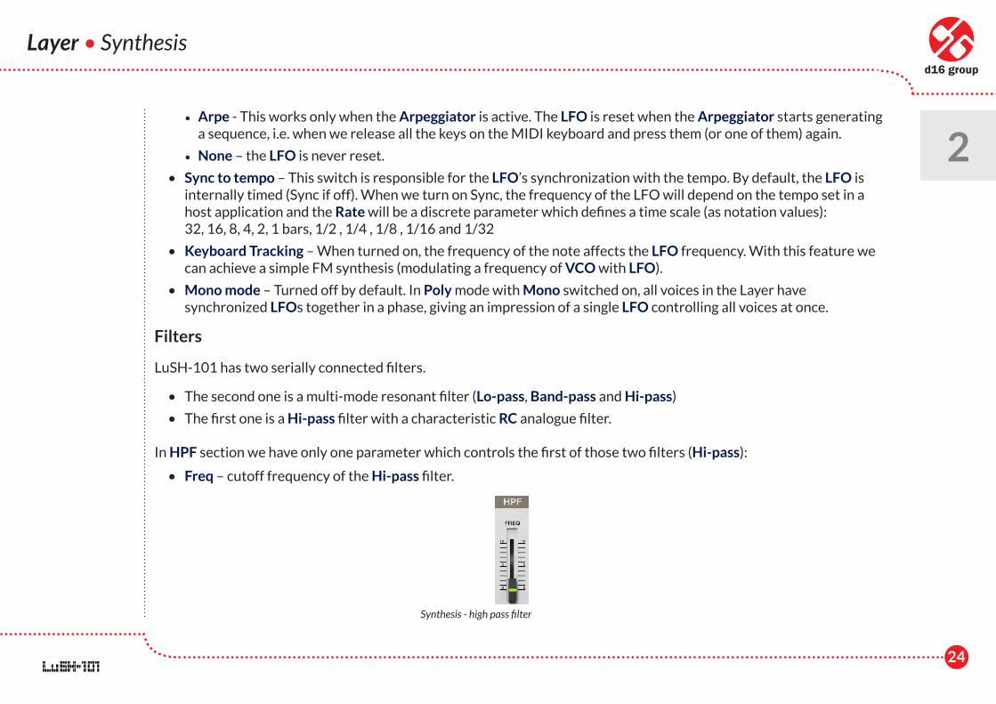
In HPF section we have only one parameter which controls the first of those two filters (Hi-pass):
• Freq – cutoff frequency of the Hi-pass filter.
Synthesis - high pass filter
25
Layer • Synthesis
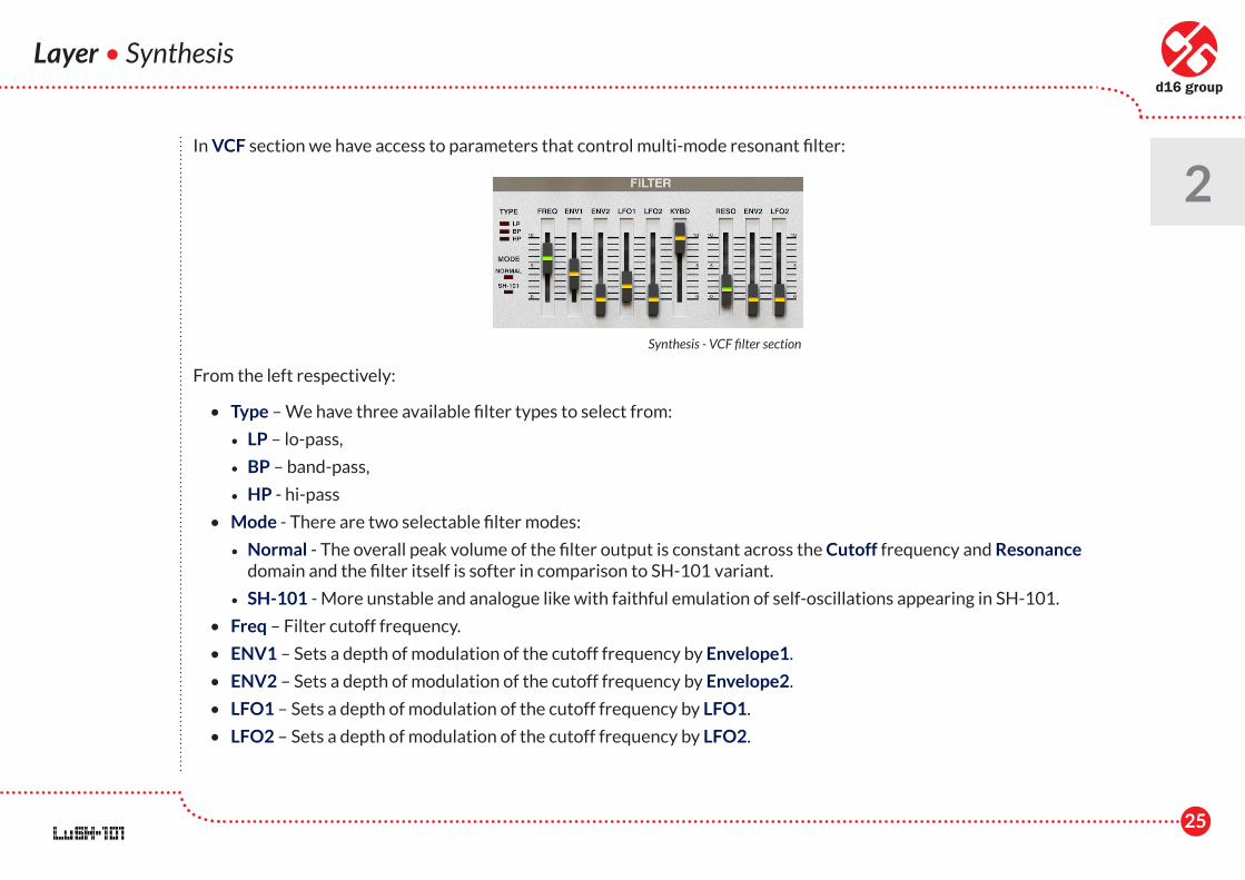
2In VCF section we have access to parameters that control multi-mode resonant filter:
From the left respectively:
• Type – We have three available filter types to select from:
• LP – lo-pass,
• BP – band-pass,
• HP - hi-pass
• Mode - There are two selectable filter modes:
• Normal - The overall peak volume of the filter output is constant across the Cutoff frequency and Resonance domain and the filter itself is softer in comparison to SH-101 variant.
• SH-101 - More unstable and analogue like with faithful emulation of self-oscillations appearing in SH-101.
• Freq – Filter cutoff frequency.
• ENV1 – Sets a depth of modulation of the cutoff frequency by Envelope1.
• ENV2 – Sets a depth of modulation of the cutoff frequency by Envelope2.
• LFO1 – Sets a depth of modulation of the cutoff frequency by LFO1.
• LFO2 – Sets a depth of modulation of the cutoff frequency by LFO2.
Synthesis - VCF filter section
26
Layer • Synthesis
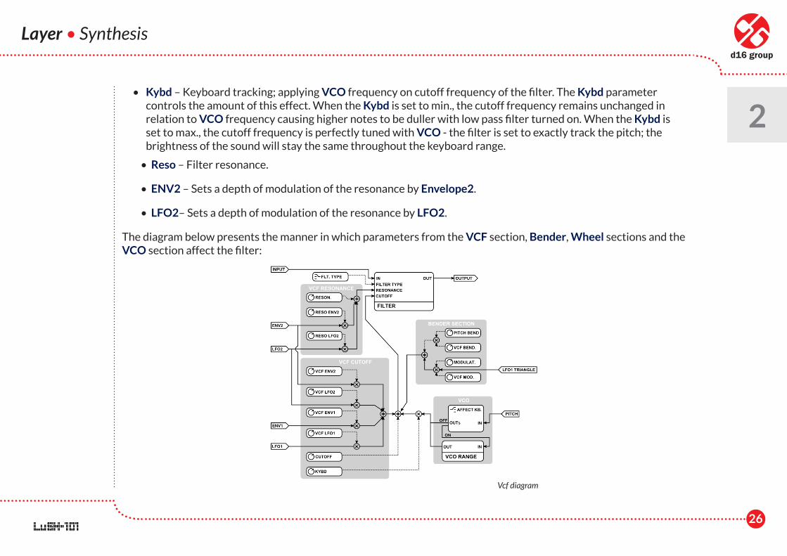
2 • Kybd – Keyboard tracking; applying VCO frequency on cutoff frequency of the filter. The Kybd parameter
controls the amount of this effect. When the Kybd is set to min., the cutoff frequency remains unchanged in relation to VCO frequency causing higher notes to be duller with low pass filter turned on. When the Kybd is set to max., the cutoff frequency is perfectly tuned with VCO - the filter is set to exactly track the pitch; the brightness of the sound will stay the same throughout the keyboard range.
• Reso – Filter resonance.
• ENV2 – Sets a depth of modulation of the resonance by Envelope2.
• LFO2– Sets a depth of modulation of the resonance by LFO2.
The diagram below presents the manner in which parameters from the VCF section, Bender, Wheel sections and the VCO section affect the filter:
Vcf diagram
27
Layer • Synthesis
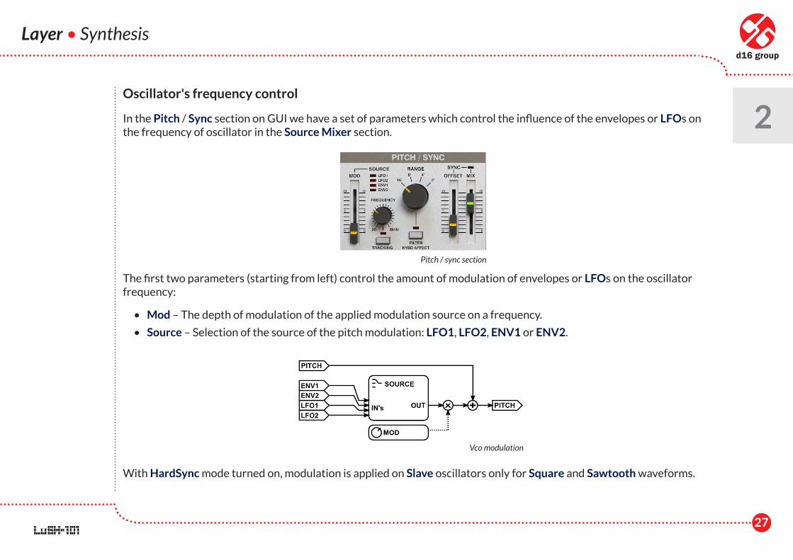
2Oscillator's frequency control
In the Pitch / Sync section on GUI we have a set of parameters which control the influence of the envelopes or LFOs on the frequency of oscillator in the Source Mixer section.
The first two parameters (starting from left) control the amount of modulation of envelopes or LFOs on the oscillator frequency:
• Mod – The depth of modulation of the applied modulation source on a frequency.
• Source – Selection of the source of the pitch modulation: LFO1, LFO2, ENV1 or ENV2.
With HardSync mode turned on, modulation is applied on Slave oscillators only for Square and Sawtooth waveforms.
Pitch / sync section
Vco modulation
28
Layer • Synthesis
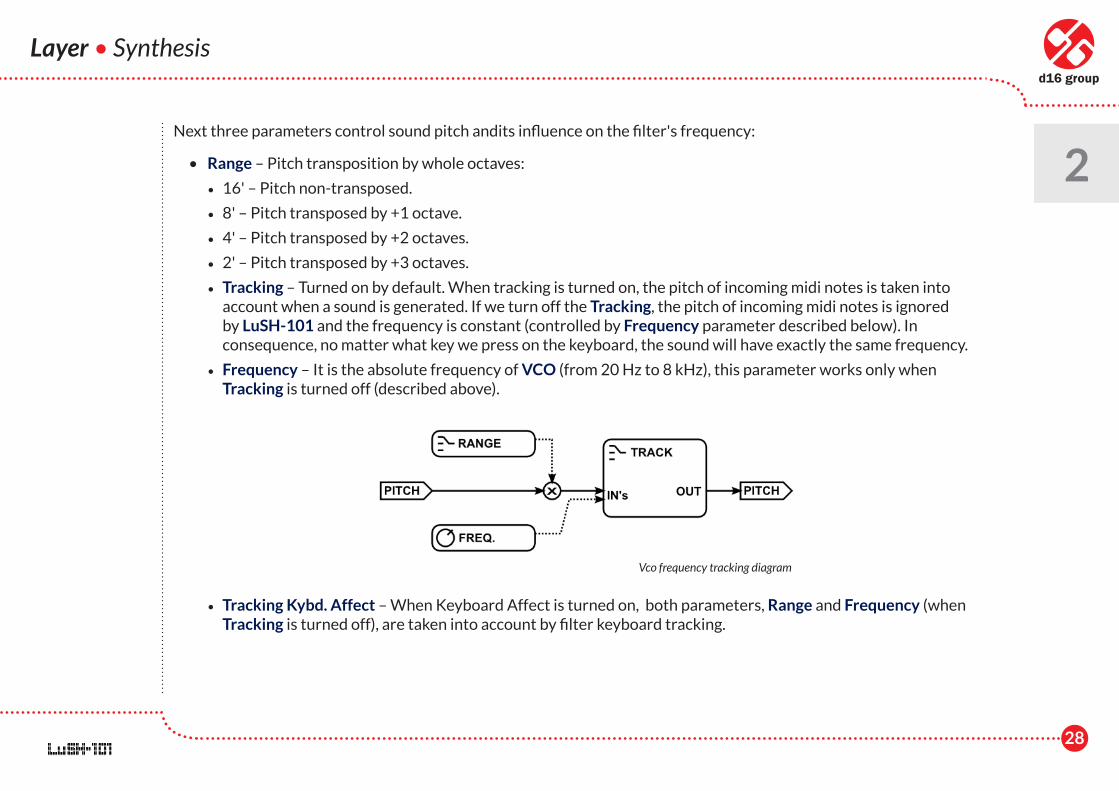
2Next three parameters control sound pitch andits influence on the filter's frequency:
• Range – Pitch transposition by whole octaves:
• 16' – Pitch non-transposed.
• 8' – Pitch transposed by +1 octave.
• 4' – Pitch transposed by +2 octaves.
• 2' – Pitch transposed by +3 octaves.
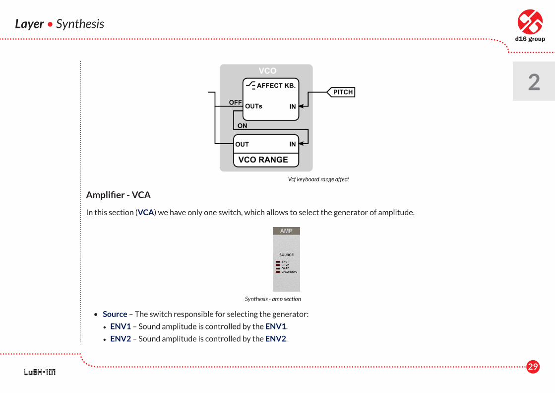
• Tracking – Turned on by default. When tracking is turned on, the pitch of incoming midi notes is taken into account when a sound is generated. If we turn off the Tracking, the pitch of incoming midi notes is ignored by LuSH-101 and the frequency is constant (controlled by Frequency parameter described below). In consequence, no matter what key we press on the keyboard, the sound will have exactly the same frequency.
• Frequency – It is the absolute frequency of VCO (from 20 Hz to 8 kHz), this parameter works only when Tracking is turned off (described above).
• Tracking Kybd. Affect – When Keyboard Affect is turned on, both parameters, Range and Frequency (when Tracking is turned off), are taken into account by filter keyboard tracking.
Vco frequency tracking diagram
29
Layer • Synthesis
2
Amplifier - VCA
In this section (VCA) we have only one switch, which allows to select the generator of amplitude.
• Source – The switch responsible for selecting the generator:
• ENV1 – Sound amplitude is controlled by the ENV1.
• ENV2 – Sound amplitude is controlled by the ENV2.
Vcf keyboard range affect
Synthesis - amp section
30
Layer • Synthesis
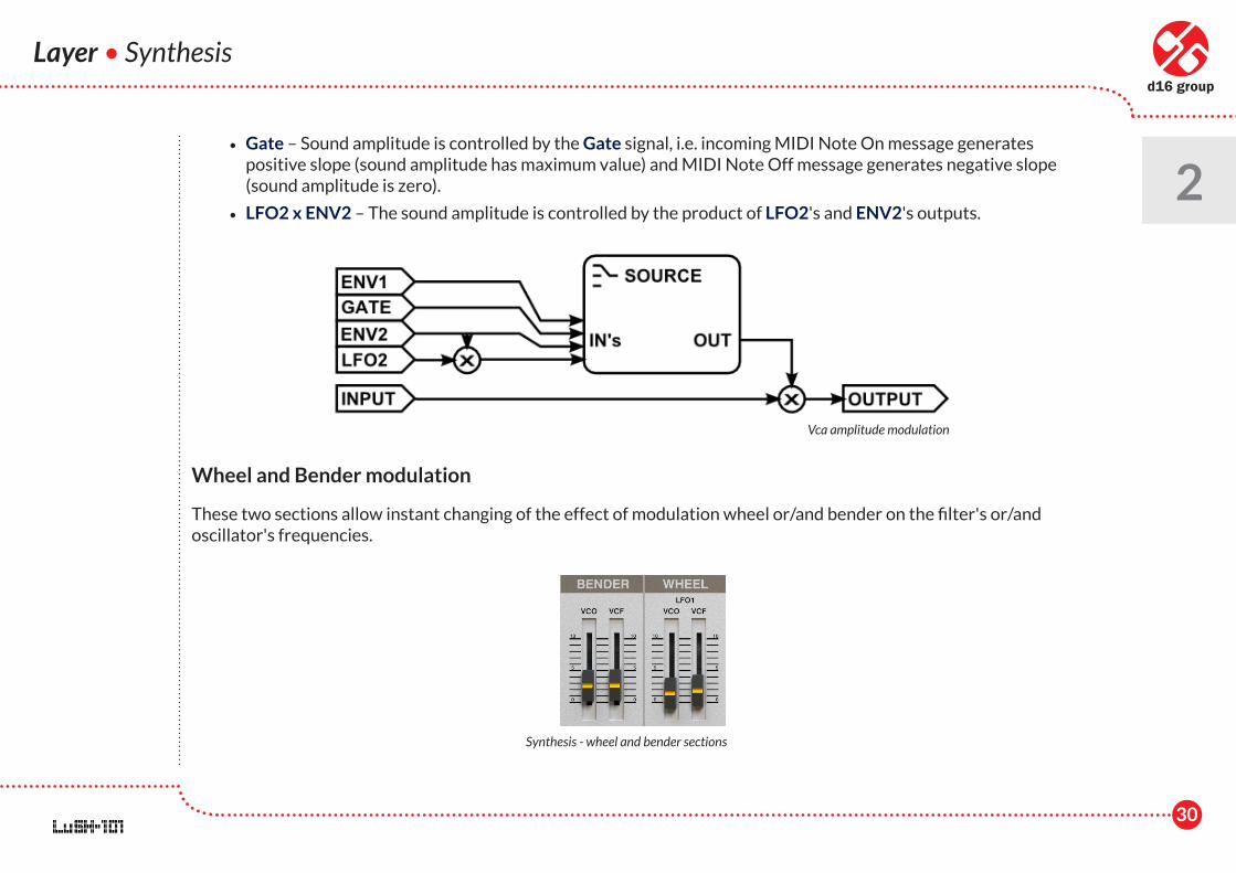
2 • Gate – Sound amplitude is controlled by the Gate signal, i.e. incoming MIDI Note On message generates
positive slope (sound amplitude has maximum value) and MIDI Note Off message generates negative slope (sound amplitude is zero).
• LFO2 x ENV2 – The sound amplitude is controlled by the product of LFO2's and ENV2's outputs.
Wheel and Bender modulation
These two sections allow instant changing of the effect of modulation wheel or/and bender on the filter's or/and oscillator's frequencies.
Vca amplitude modulation
Synthesis - wheel and bender sections

31
• Wheel – Allows controlling, through the modulation wheel, the depth of effect of LFO1 on the oscillator frequency or/and filter cutoff frequency. We have the following parameters:
• VCO – The depth of modulation of the oscillator's frequency by LFO1's output – gives a vibratto effect controlled by the modulation wheel.
• VCF – The depth of modulation of the filter frequency by LFO1's output.
Note: Please note that the waveform of the LFO1 output for the wheel section is always triangular. The waveform parameter in LFO1 section is ignored here.
• Bender – Allows using the pitch bender to control oscillator's frequency or/and filter cutoff frequency. There are two parameters:
• VCO – The range the bender affects the oscillator's frequency.
• VCF – The range the bender affects the filter cutoff frequency.
The diagram below presents the manner in which VCO parameters in Bender and Wheel sections influence the oscillator frequency:
Layer • Synthesis
2
Wheel and bender affecting vco
32
Layer • Synthesis
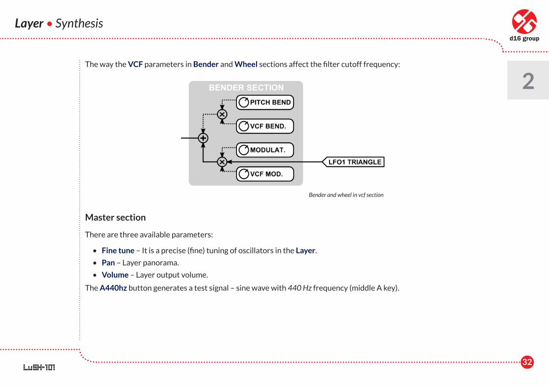
2The way the VCF parameters in Bender and Wheel sections affect the filter cutoff frequency:
Master section
There are three available parameters:
• Fine tune – It is a precise (fine) tuning of oscillators in the Layer.
• Pan – Layer panorama.
• Volume – Layer output volume.
The A440hz button generates a test signal – sine wave with 440 Hz frequency (middle A key).
Bender and wheel in vcf section
33
Layer • Insert effects
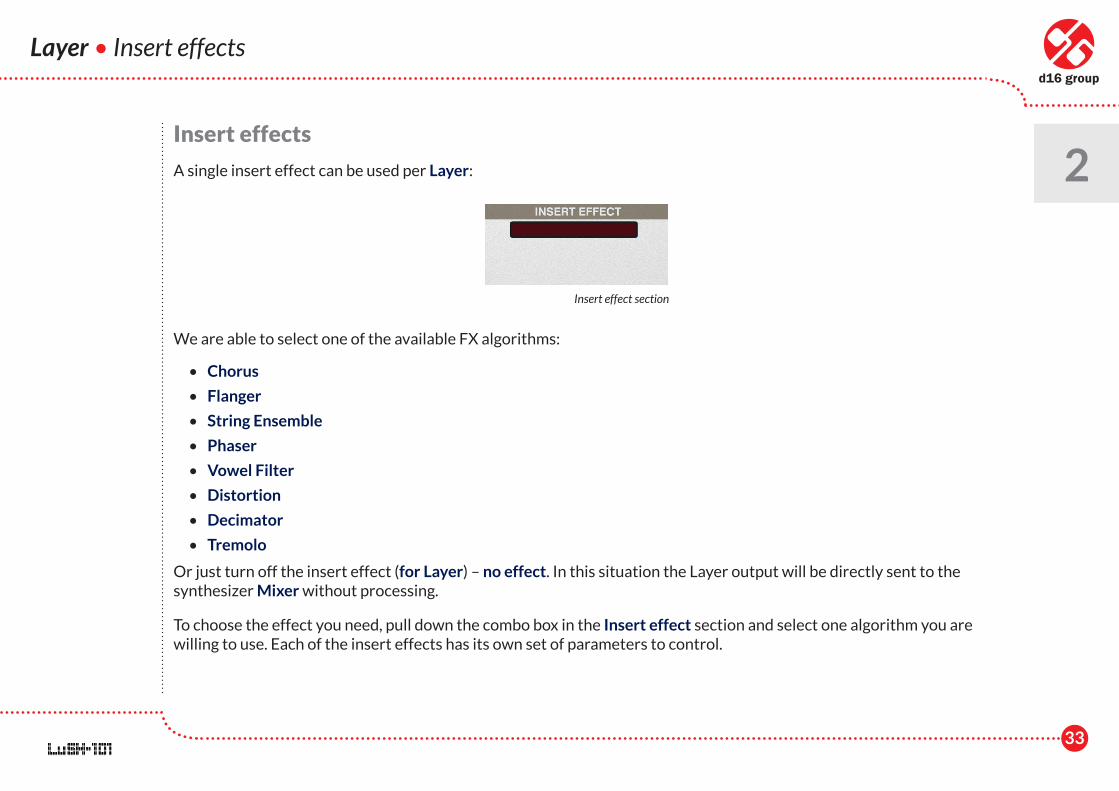
2Insert effects
A single insert effect can be used per Layer:
We are able to select one of the available FX algorithms:
• Chorus
• Flanger
• String Ensemble
• Phaser
• Vowel Filter
• Distortion
• Decimator
• Tremolo
Or just turn off the insert effect (for Layer) – no effect. In this situation the Layer output will be directly sent to the synthesizer Mixer without processing.
To choose the effect you need, pull down the combo box in the Insert effect section and select one algorithm you are willing to use. Each of the insert effects has its own set of parameters to control.
Insert effect section

34
Layer • Insert effects
2Chorus
• Speed – LFO speed. We have three fixed values:
• Slow
• Fast
• Mid
• Mode – Chorus mode.
• Thin – Single delay line.
• Fat – Double delay line.
• Stereo – Stereo phase shift between LFO controlling delay lines for left and right channels.
• Dry / Wet – Proportions between processed and unprocessed sound.
Flanger
Insert effect - chorus
Insert effect - flanger
35
Layer • Insert effects
2 • Depth – Depth of flanger effect.
• Rate – LFO frequency.
• Feedback – Flanger feedback.
• Invert – Inverting flanger feedback.
• Dry / wet – Proportions between processed and unprocessed sound.
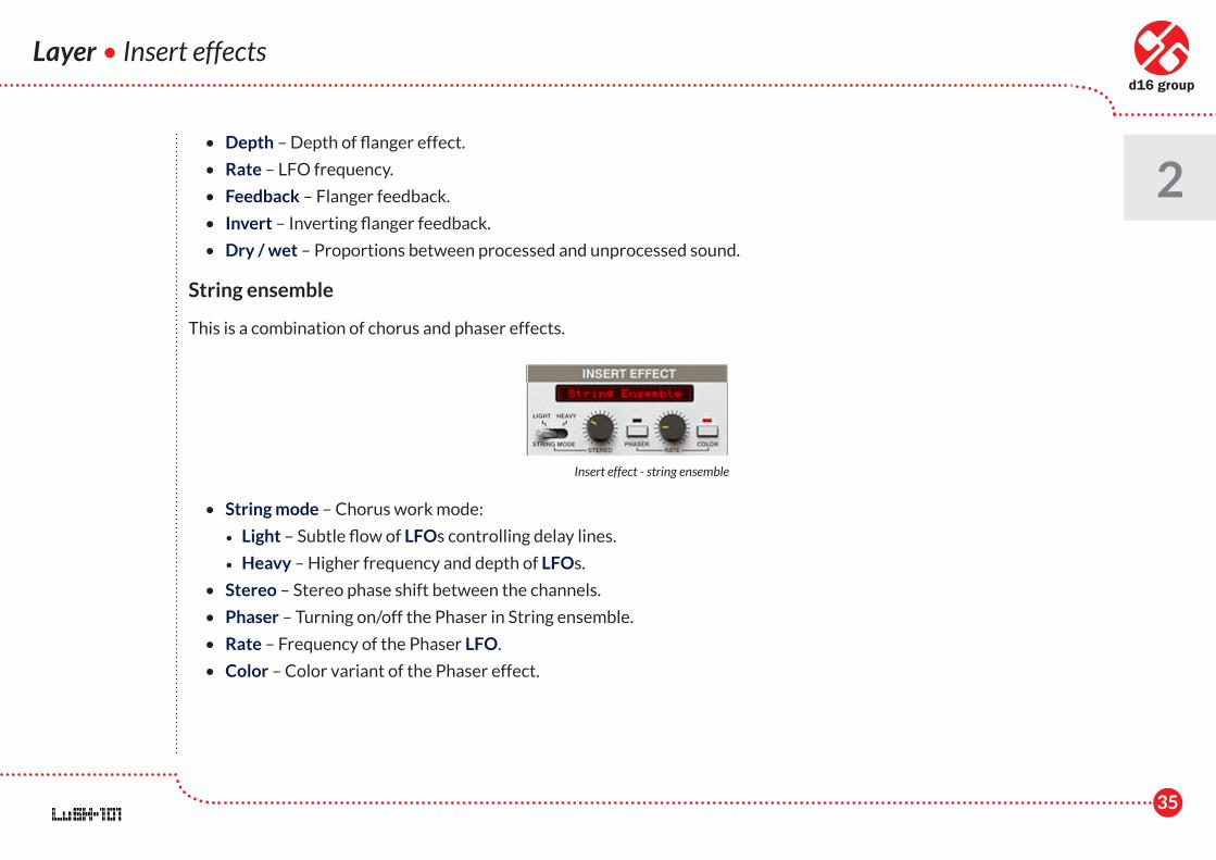
String ensemble
This is a combination of chorus and phaser effects.
• String mode – Chorus work mode:
• Light – Subtle flow of LFOs controlling delay lines.
• Heavy – Higher frequency and depth of LFOs.
• Stereo – Stereo phase shift between the channels.
• Phaser – Turning on/off the Phaser in String ensemble.
• Rate – Frequency of the Phaser LFO.
• Color – Color variant of the Phaser effect.
Insert effect - string ensemble
36
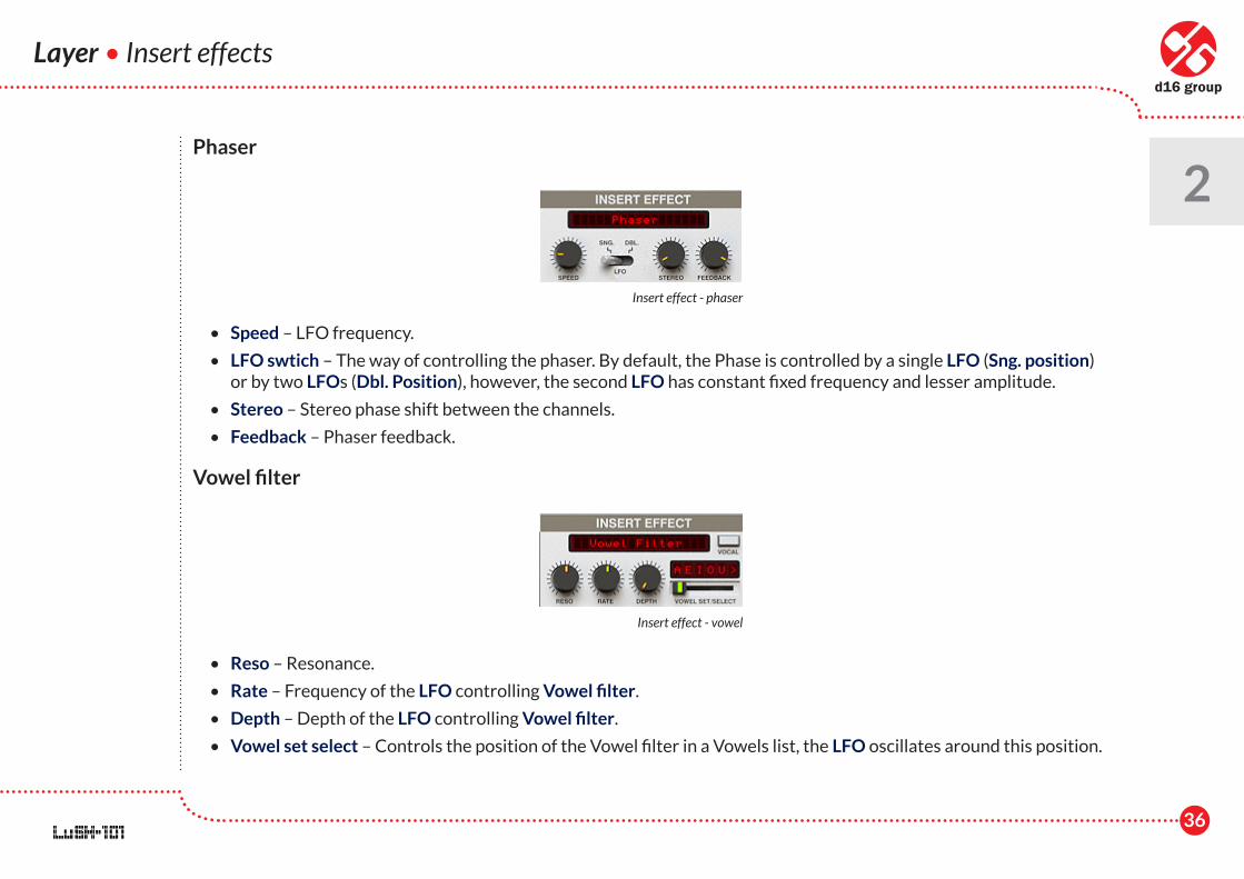
Phaser
• Speed – LFO frequency.
• LFO swtich – The way of controlling the phaser. By default, the Phase is controlled by a single LFO (Sng. position) or by two LFOs (Dbl. Position), however, the second LFO has constant fixed frequency and lesser amplitude.
• Stereo – Stereo phase shift between the channels.
• Feedback – Phaser feedback.
Vowel filter
• Reso – Resonance.
• Rate – Frequency of the LFO controlling Vowel filter.
• Depth – Depth of the LFO controlling Vowel filter.
• Vowel set select – Controls the position of the Vowel filter in a Vowels list, the LFO oscillates around this position.
Layer • Insert effects
2
Insert effect - phaser
Insert effect - vowel
37
Layer • Insert effects
2
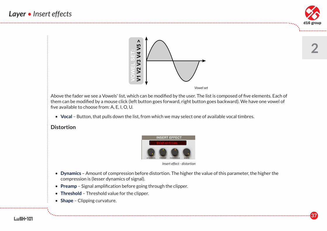
Above the fader we see a Vowels' list, which can be modified by the user. The list is composed of five elements. Each of them can be modified by a mouse click (left button goes forward, right button goes backward). We have one vowel of five available to choose from: A, E, I, O, U.
• Vocal – Button, that pulls down the list, from which we may select one of available vocal timbres.
Distortion
• Dynamics – Amount of compression before distortion. The higher the value of this parameter, the higher the compression is (lesser dynamics of signal).
• Preamp – Signal amplification before going through the clipper.
• Threshold – Threshold value for the clipper.
• Shape – Clipping curvature.
Vowel set
Insert effect - distortion
38
Layer • Insert effects
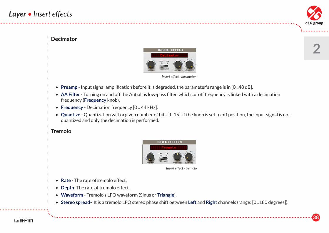
2Decimator
• Preamp - Input signal amplification before it is degraded, the parameter's range is in [0 ..48 dB].
• AA Filter - Turning on and off the Antialias low-pass filter, which cutoff frequency is linked with a decimation frequency (Frequency knob).
• Frequency - Decimation frequency [0 .. 44 kHz].
• Quantize - Quantization with a given number of bits [1..15], if the knob is set to off position, the input signal is not quantized and only the decimation is performed.
Tremolo
• Rate - The rate oftremolo effect.
• Depth–The rate of tremolo effect.
• Waveform - Tremolo's LFO waveform (Sinus or Triangle).
• Stereo spread– It is a tremolo LFO stereo phase shift between Left and Right channels (range: [0 ..180 degrees]).
Insert effect - decimator
Insert effect - tremolo
39
Layer • Arpeggiator
2Arpeggiator
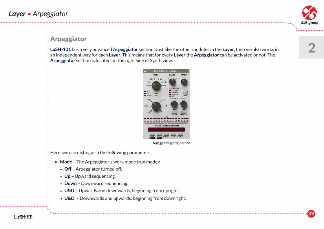
LuSH-101 has a very advanced Arpeggiator section. Just like the other modules in the Layer, this one also works in an independent way for each Layer. This means that for every Layer the Arpeggiator can be activated or not. The Arpeggiator section is located on the right side of Synth view.
Here, we can distinguish the following parameters:
• Mode – The Arpeggiator's work mode (run mode):
• Off – Arpeggiator turned off.
• Up – Upward sequencing.
• Down – Downward sequencing.
• U&D – Upwards and downwards, beginning from upright.
• U&D – Downwards and upwards, beginning from downright.
Arpeggiator (gater) section
40
• Random – Random order sequencing.
• Manual – Sequencing accordingly with the order of pressed keys on the MIDI keyboard.
• Range – Arpeggiator range expressed in octaves.
• Repeat – Number of repetitions of the Arpeggiator sequence in each octave.
• Rate – Rhythmical value of a single step in the Arpeggiator sequence: 1 bar, 1/2 , 1/4 , 1/8 , 1/16 , 1/32 and 1/64
Additionally with the help of three LEDs: Full / Dot / Tri, working in radio mode, we can modify the rhythmical value of the Rate parameter:
• Full – Full note.
• Dot – Dotted note.
• Tri – Triplet.
• Shuffle – Shuffle strength for generated sequence.
• Gate – Note length for a single step in a generated sequence. If the Gate is set to 100%, notes generated in an Arpeggiator sequence will be overlapping each other (Legato)
• Chord – When turned off, the Arpeggiator behaves regularly (it generates monophonical sequence accordingly with other settings), but if it is turned on, the Arpeggiator acts as a gater. Pressing the Chord on the MIDI keyboard will cause the Arpeggiator to play all sounds at once in a single step. Please note, that to use the Chord mode, you need to set an adequate polyphony to make it work.
• Hold mode – Typical Hold mode causes the Arpeggiator sequence to constantly play, despite the fact the MIDI keys are no longer held on the keyboard. Successively pressed keys will be added to the Arpeggiator sequence, in other words, incoming MIDI Note off messages are ignored. In LuSH-101 we have a few Hold modes to select from:
• Off – Hold is inactive.
• Normal – Hold mode works regularly (as described above).
Layer • Arpeggiator
2
41
• Trigger – When keys are pressed on the keyboard, the notes corresponding to them are added to a sequence. When we press and hold, for example, two keys, they are added to a sequence, even if we release one of them, two notes are still in queue (playing). Even if we release all pressed keys, the sequence will be still playing, however when at this point we press any notes again on the MIDI keyboard, the notes previously played are removed from the sequence, and the new ones pressed will be added to sequence immediately.
• Toggle – In this mode the MIDI keyboard works in Toggle mode; pressing one key adds a corresponding note to the Arpeggiator's sequence, pressing the same key once again removes the note from the sequence.
• Clear keys – irrespective of the chosen Hold mode, using this button will remove all the notes from the Arpeggiator sequence, which were earlier added with Hold mode. Using Clear keys button while holding CTRL performs the action for all Layers in LuSH-101.
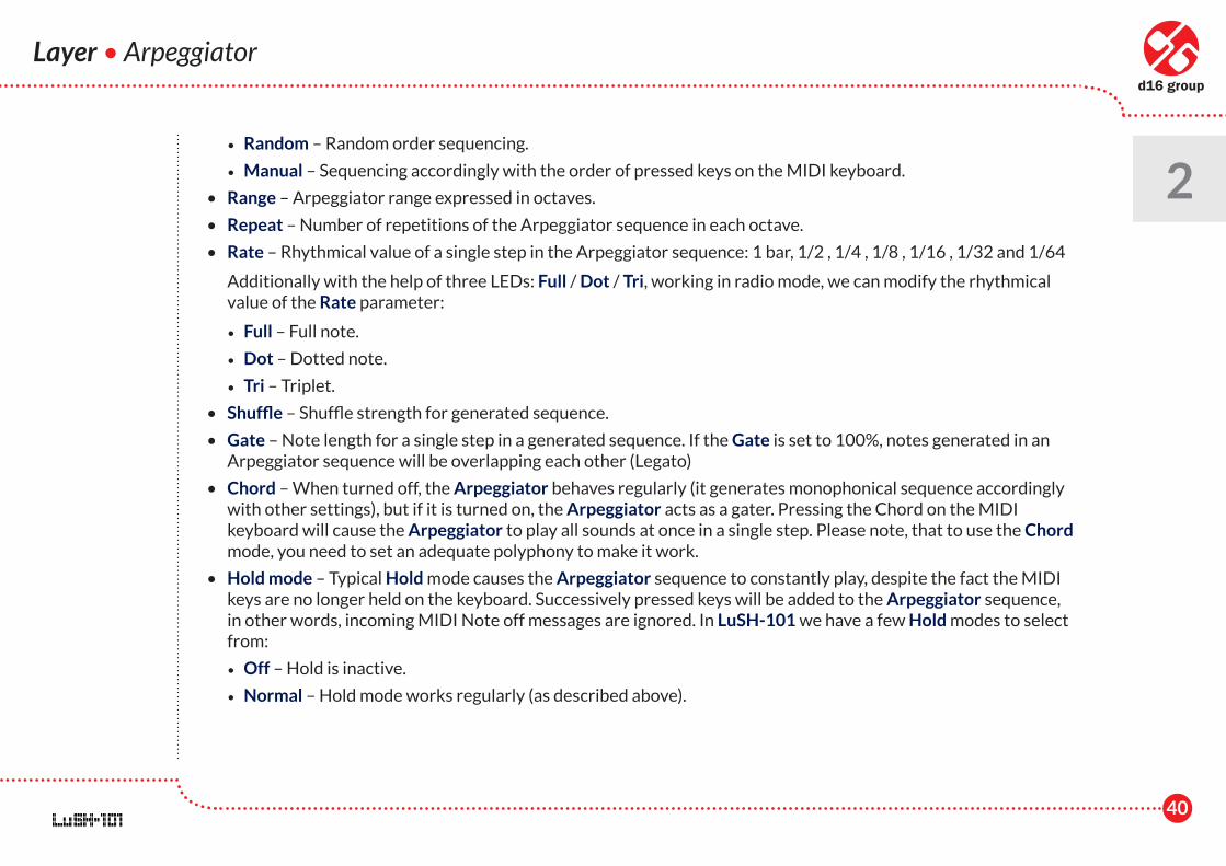
In the bottom part of Arpeggio / Gate section there are two rows of LEDs. Each column accords with a single step of the Arpeggiator sequence – although that single complete cycle of the Arpeggiator can be much longer, because of Range and Repeat values or/and the number of keys pressed on the MIDI keyboard simultaneously.
16 LEDs correspond to 16 steps. When the 16th step is reached, the Arpeggiator goes back to the 1st step. LEDs work in toggle mode, and therefore:
• The first row (Gate) displays whether the step is played or not. If LED is set, the step is played. If LED is unset, then the pause is generated and the note that should appear in this place is omitted.
• The second row (Tie) is used for tying the notes together. If the LED is set, the step corresponding to that LED is tied together with the next step. Setting the adjacent LEDs will tie all the notes into a single longer one.
Layer • Arpeggiator
2
Arpeggiator (gater) section
42
Layer • Arpeggiator
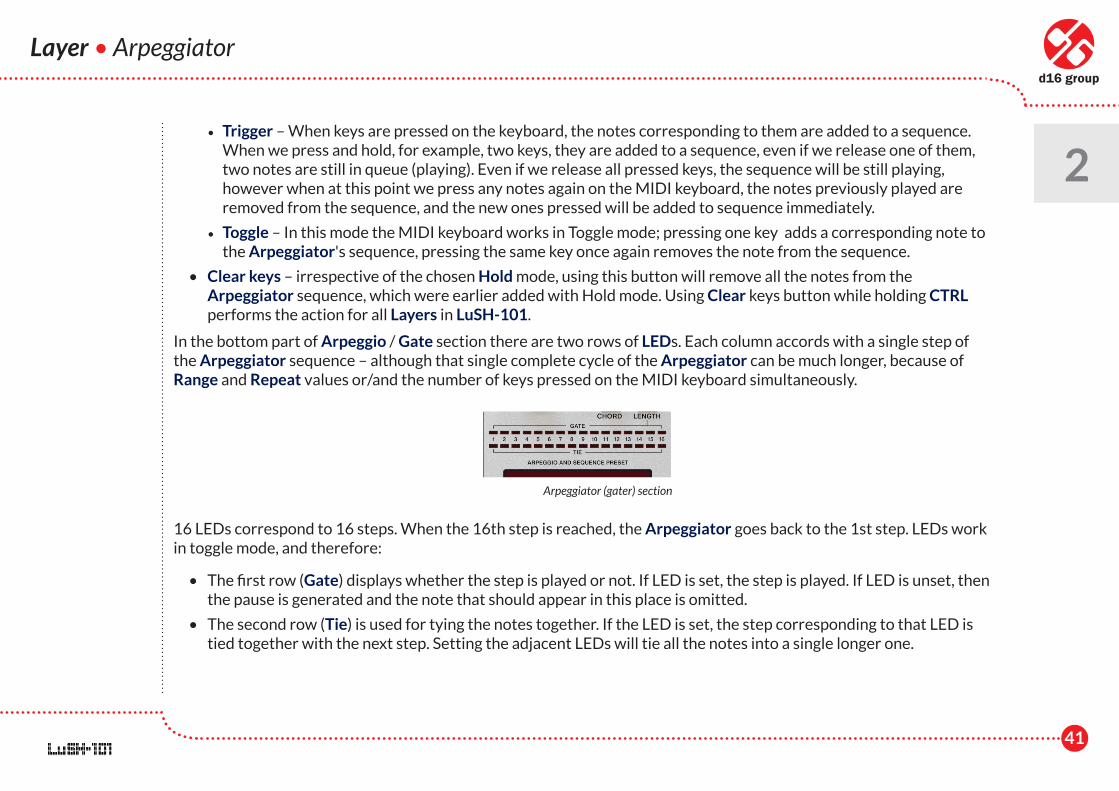
2There is also a Padlock icon in the upper left corner of the Arpeggiator section:
It is used for locking all parameters within the Layer's Arpeggiator, thus preventing overwriting their values when the Timbre preset or Global Preset is loaded. To read the details go to Preset Management chapter.
Examples
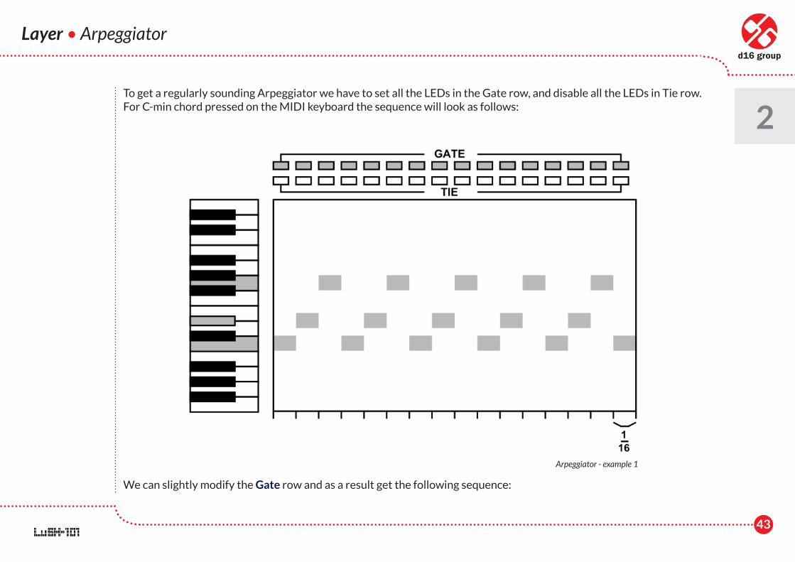
Let's assume the following values of the Arpeggiator's parameters:
Range = 1 oct
Mode = up
Repeat = 1x
Rate = 1/16 (full)
Apreggiator's padlock
43
To get a regularly sounding Arpeggiator we have to set all the LEDs in the Gate row, and disable all the LEDs in Tie row. For C-min chord pressed on the MIDI keyboard the sequence will look as follows:
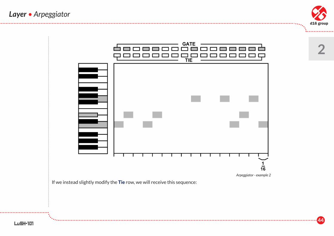
We can slightly modify the Gate row and as a result get the following sequence:
Layer • Arpeggiator
2
Arpeggiator - example 1
44
Layer • Arpeggiator
2
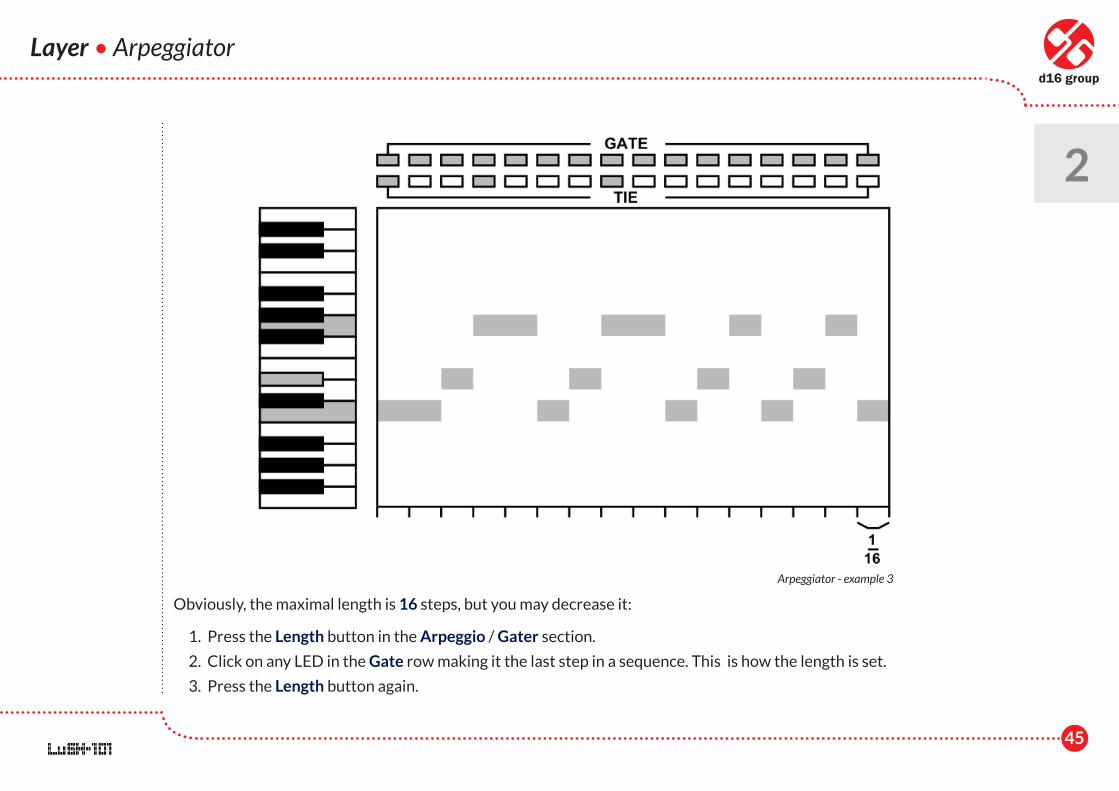
If we instead slightly modify the Tie row, we will receive this sequence:
Arpeggiator - example 2
45
Layer • Arpeggiator
2
Obviously, the maximal length is 16 steps, but you may decrease it:
1. Press the Length button in the Arpeggio / Gater section.
2. Click on any LED in the Gate row making it the last step in a sequence. This is how the length is set.
3. Press the Length button again.
Arpeggiator - example 3
46
Layer • Arpeggiator • Modulation Matrix
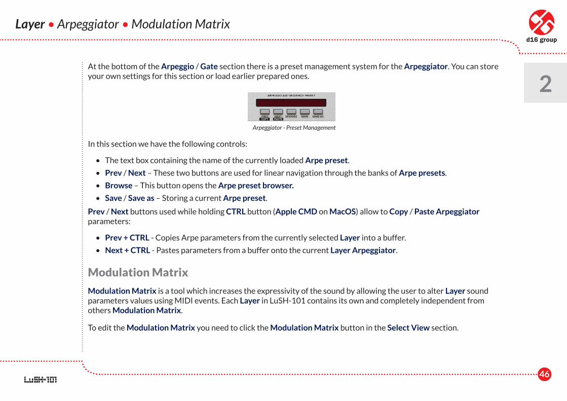
2At the bottom of the Arpeggio / Gate section there is a preset management system for the Arpeggiator. You can store your own settings for this section or load earlier prepared ones.
In this section we have the following controls:
• The text box containing the name of the currently loaded Arpe preset.
• Prev / Next – These two buttons are used for linear navigation through the banks of Arpe presets.
• Browse – This button opens the Arpe preset browser.
• Save / Save as – Storing a current Arpe preset.
Prev / Next buttons used while holding CTRL button (Apple CMD on MacOS) allow to Copy / Paste Arpeggiator parameters:
• Prev + CTRL - Copies Arpe parameters from the currently selected Layer into a buffer.
• Next + CTRL - Pastes parameters from a buffer onto the current Layer Arpeggiator.
Modulation Matrix
Modulation Matrix is a tool which increases the expressivity of the sound by allowing the user to alter Layer sound parameters values using MIDI events. Each Layer in LuSH-101 contains its own and completely independent from others Modulation Matrix.
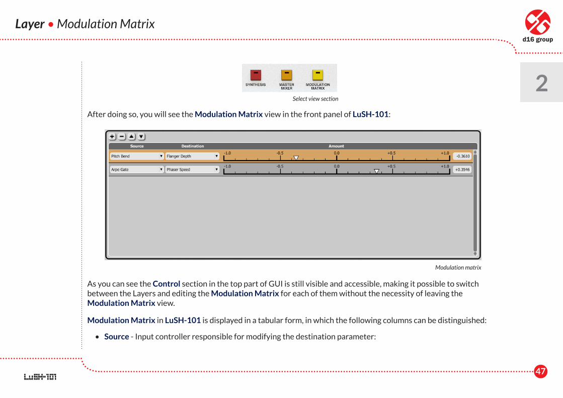
To edit the Modulation Matrix you need to click the Modulation Matrix button in the Select View section.
Arpeggiator - Preset Management
47
After doing so, you will see the Modulation Matrix view in the front panel of LuSH-101:
As you can see the Control section in the top part of GUI is still visible and accessible, making it possible to switch between the Layers and editing the Modulation Matrix for each of them without the necessity of leaving the Modulation Matrix view.
Modulation Matrix in LuSH-101 is displayed in a tabular form, in which the following columns can be distinguished:
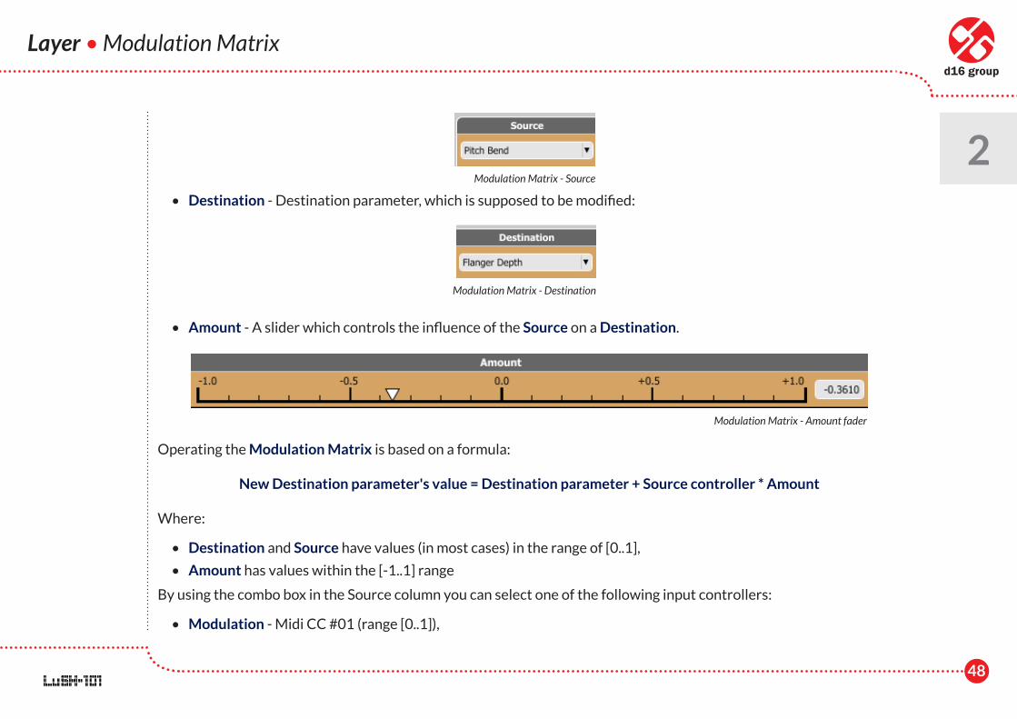
• Source - Input controller responsible for modifying the destination parameter:
Layer • Modulation Matrix
2Select view section
Modulation matrix
48
Layer • Modulation Matrix
2 • Destination - Destination parameter, which is supposed to be modified:
• Amount - A slider which controls the influence of the Source on a Destination.
Operating the Modulation Matrix is based on a formula:
New Destination parameter's value = Destination parameter + Source controller * Amount
Where:
• Destination and Source have values (in most cases) in the range of [0..1],
• Amount has values within the [-1..1] range
By using the combo box in the Source column you can select one of the following input controllers:
• Modulation - Midi CC #01 (range [0..1]),
Modulation Matrix - Source
Modulation Matrix - Destination
Modulation Matrix - Amount fader
49
Layer • Modulation Matrix
2 • Expression - Midi CC #11 (range [0..1]),
• Pitch Bend - Midi Pitch Bender (range [-1 .. 1]),
• Velocity - Midi Note velocity (range [0..1]),
• Pitch - Values (range [0..1]) of Pitch Tracking (see the Timbre settings chapter) assigned to each and every MIDI note,
• Channel Pressure - MIDI Channel Aftertouch (range [0..1]),
• Sustain - Midi CC #64 / Sustain pedal (gets one of two values; {0,1})
• Arpe Gate - Gate step sequence from Layer's Arpeggiator (sequence has two-state steps and because of that sequence, each step can have one of two values; {0,1})
• Arpe Tie - Tie step sequence from Layer's Arpeggiator (sequence has two-state steps and because of that sequence, each step can have one of two values; {0,1})
By using the combo box in the Destination column we can select one from almost all available sound parameters of the Layer.
In the Modulation Matrix a single controller (Source) can modify a few sound parameters (Destinations) at the same time when few rows with same Source are added. Also a few controllers (Sources) can modify a single parameter when a few rows with identical Destination are added.
Note: It should be remembered that in the case of selecting Velocity or Pitch as a Source in the Modulation Matrix, there will be no access to all parameters in the Destination column, because both, Velocity and Pitch, are source controllers working per voice, and some of the parameters affect all Layer voices (e.g.Insert effects parameters). To those kind ofparameters Velocity and Pitch sources cannot be assigned.
On left upper corner of the Modulation Matrix there are four buttons devoted to basic editing actions:
- Adding a new row to a Modulation Matrix,
- Removing a selected row from a Modulation Matrix,
50
Layer • Modulation Matrix
2 - Moving up a selected row,
- Moving down a selected row
A row can be selected by a mouse-click on any of its controls, (selected row becomes highlighted).
Voice Volume - A special destination parameter
In the Destination column we have a specific parameter available which can be selected, namely Voice Volume (in a Source Mixer node). This parameter has no equivalent in any of the GUI parameters. It controls the volume of a single voice generated by the synthesizer. Using it as the Destination in the Modulation Matrix enables achieving typical volume dynamics. This parameter works according to a slightly different formula than other Destinations in the Modulation Matrix. When the Amount value is set to 0, the Voice Volume is not modified at all (lack of volume dynamics). In case of setting the Amount to 1, the MIDI note Veloticy affects the Voice Volume to full extend (maximum Volume dynamics) in accordance witha principle: The greater the Velocity of a MIDI note, the louder the sound is generated. But if we set the Amount to -1, then the note Velocity is inversely proportional to the sound volume (Voice Volume); the greater the velocity value of a MIDI note, the quieter the sound is generated.
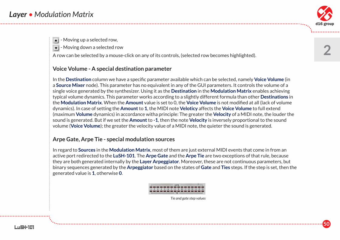
Arpe Gate, Arpe Tie - special modulation sources
In regard to Sources in the Modulation Matrix, most of them are just external MIDI events that come in from an active port redirected to the LuSH-101. The Arpe Gate and the Arpe Tie are two exceptions of that rule, because they are both generated internally by the Layer Arpeggiator. Moreover, these are not continuous parameters, but binary sequences generated by the Arpeggiator based on the states of Gate and Ties steps. If the step is set, then the generated value is 1, otherwise 0.
Tie and gate step values
51
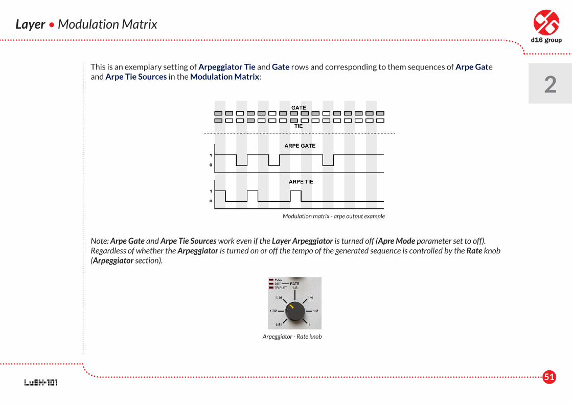
This is an exemplary setting of Arpeggiator Tie and Gate rows and corresponding to them sequences of Arpe Gate and Arpe Tie Sources in the Modulation Matrix:
Note: Arpe Gate and Arpe Tie Sources work even if the Layer Arpeggiator is turned off (Apre Mode parameter set to off). Regardless of whether the Arpeggiator is turned on or off the tempo of the generated sequence is controlled by the Rate knob (Arpeggiator section).
Layer • Modulation Matrix
2
Modulation matrix - arpe output example
Arpeggiator - Rate knob
52
Layer • Timbre Preset Settings
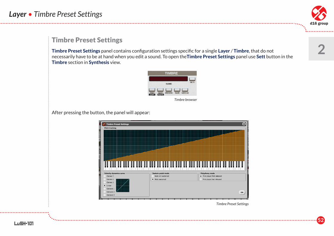
2Timbre Preset Settings
Timbre Preset Settings panel contains configuration settings specific for a single Layer / Timbre, that do not necessarily have to be at hand when you edit a sound. To open theTimbre Preset Settings panel use Sett button in the Timbre section in Synthesis view.
After pressing the button, the panel will appear:
Timbre browser
Timbre Preset Settings
53
Layer • Timbre Preset Settings
2The panel contains the following controls:
• Pitch tracking - A graph which allows to assign a certain value in the range of [1..100] to each MIDI note coming into the Layer. This set of values is used in the Modulation Matrix as a Source :Pitch. Depending on a MIDI note received by LuSH-101 a corresponding value is returned as a Pitch (rescaled to the range [0..1]) in the Modulation Matrix. Editing the Pitch tracking values can be performed in two ways:
• Freehand drawing, using the mouse while holding the left button.
• Linearly interpolated drawing, using and clicking the right button. The first click starts a line, successive click starts another line at the end of the first one, and so on. If you are done, just finish with a left mouse click.
• Velocity dynamics curve - Allows to select between seven different dynamic curves, the one selected is taken into account in Modulation Matrix (Velocity).
• Convex 3
• Convex 2
• Convex 1
• Linear
• Concave 1
• Concave 2
• Concave 3
Linear is the default one.
• Sustain pedal mode - Sustain pedal apart from its basic task of sustaining the played notes, can be also used as a Source in the Modulation Matrix. Therefore we might want to disable sustaining the notes by the pedal, to limit its usage to the Modulation Matrix only. It is possible to perform this action using this option. There are two variants we can select from:
• Note not sustained - Sustain pedal does not sustaining notes and works in the Modulation Matrix only.
54
Layer • Timbre Preset Settings
2 • Note sustained - (default value) Sustain pedal fulfils its basic function and sustaining notes when we press it and
at the same time it can be used as a Source for the Modulation Matrix.
• Polyphony mode - Polyphony for the Layer is limited by a set of voices / generators, that are allocated to the individual MIDI notes played on the keyboard. If polyphony is too small then during the playback of complex keyboard phrases, sounds, which were triggered earlier by MIDI notes and are still playing, need to be stopped by successively and continuously incoming new MIDI notes (because of the limited polyphony). This concerns mainly sounds with longer release times. In LuSH-101 we can choose how notes should be distributed among available voices of polyphony (the order in which voices should be assigned to incoming notes and later released). There are two modes built-in:
• First played first released - (default value) This way is analogous to a queue, in which a first assigned voice to a note (considering the timeline) will be also the first one released - Method inspired by Korg's analogue synthesizers.
• First played last released - Voices management is done in a way similar to a stack, where the last assigned voice to a note (considering the timeline) will be also the first one released - This method was inspired by Roland's analogue synthesizers.
All settings from the Timbre Preset Settings panel are stored along with the Timbre / Layer preset.
55
Mixer
3Mixer
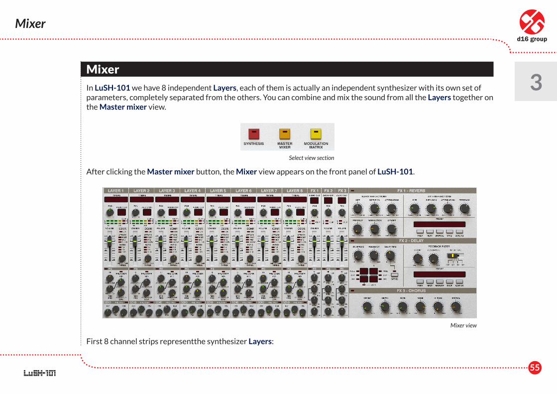
In LuSH-101 we have 8 independent Layers, each of them is actually an independent synthesizer with its own set of parameters, completely separated from the others. You can combine and mix the sound from all the Layers together on the Master mixer view.
After clicking the Master mixer button, the Mixer view appears on the front panel of LuSH-101.
First 8 channel strips representthe synthesizer Layers:
Select view section
Mixer view
56
Mixer
3
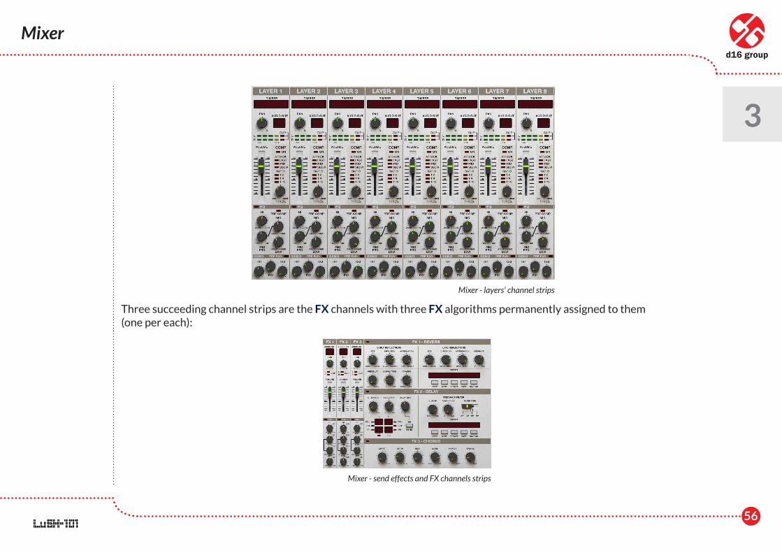
Three succeeding channel strips are the FX channels with three FX algorithms permanently assigned to them (one per each):
Mixer - layers' channel strips
Mixer - send effects and FX channels strips
57
Mixer
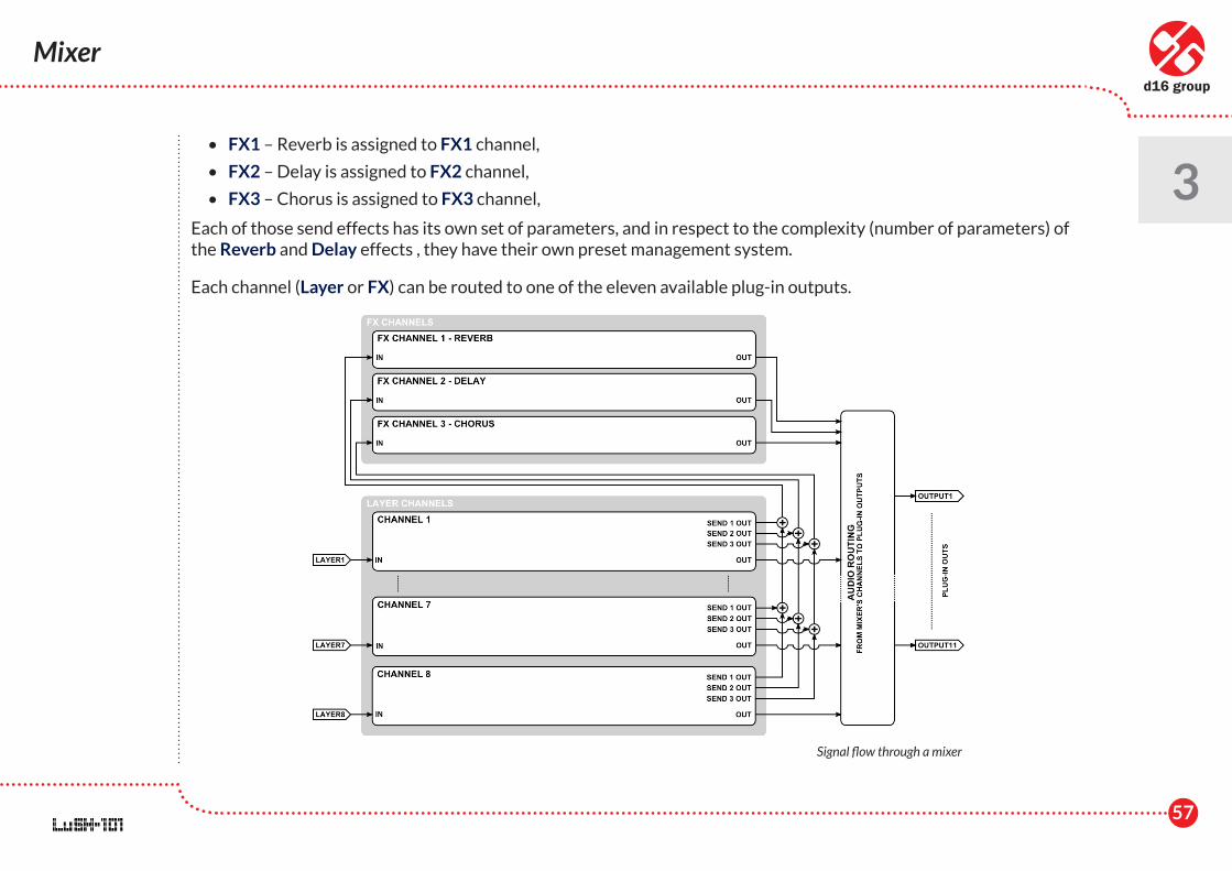
3 • FX1 – Reverb is assigned to FX1 channel,
• FX2 – Delay is assigned to FX2 channel,
• FX3 – Chorus is assigned to FX3 channel,
Each of those send effects has its own set of parameters, and in respect to the complexity (number of parameters) of the Reverb and Delay effects , they have their own preset management system.
Each channel (Layer or FX) can be routed to one of the eleven available plug-in outputs.
Signal flow through a mixer
58
Mixer • Layer channel strip
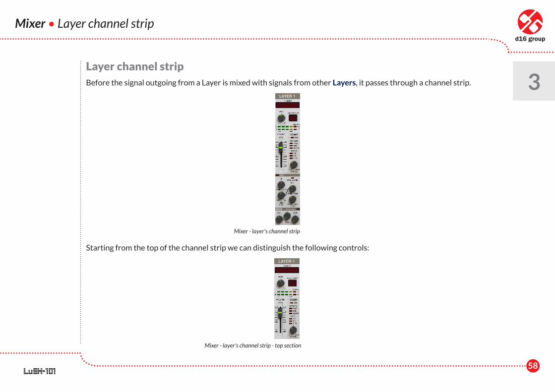
3Layer channel stripBefore the signal outgoing from a Layer is mixed with signals from other Layers, it passes through a channel strip.
Starting from the top of the channel strip we can distinguish the following controls:
Mixer - layer's channel strip
Mixer - layer's channel strip - top section
59
Mixer • Layer channel strip
3 • Timbre – This text box displays the name of the loaded timbre and allows to change the Timbre's name by clicking
on it.
• Pan – Panorama, this control corresponds to a Pan knob, which is placed in the Layer master section in the Layer tab.
• Audio out – Plug-in Audio output, which the Layer's outgoing signal is routed after processing to in a channel strip. This is conjugated with Audio output in Layer settings section in the Layer tab.
• Volume – This slider controls the output volume ofthe channel strip.
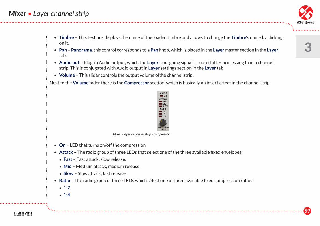
Next to the Volume fader there is the Compressor section, which is basically an insert effect in the channel strip.
• On – LED that turns on/off the compression.
• Attack – The radio group of three LEDs that select one of the three available fixed envelopes:
• Fast – Fast attack, slow release.
• Mid – Medium attack, medium release.
• Slow – Slow attack, fast release.
• Ratio – The radio group of three LEDs which select one of three available fixed compression ratios:
• 1:2
• 1:4
Mixer - layer's channel strip - compressor
60
• 1:10
• Thres. - Compressor threshold.
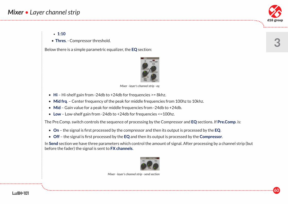
Below there is a simple parametric equalizer, the EQ section:
• Hi – Hi-shelf gain from -24db to +24db for frequencies >= 8khz.
• Mid frq. – Center frequency of the peak for middle frequencies from 100hz to 10khz.
• Mid – Gain value for a peak for middle frequencies from -24db to +24db.
• Low – Low-shelf gain from -24db to +24db for frequencies <=100hz.
The Pre.Comp. switch controls the sequence of processing by the Compressor and EQ sections. If Pre.Comp. is:
• On – the signal is first processed by the compressor and then its output is processed by the EQ.
• Off – the signal is first processed by the EQ and then its output is processed by the Compressor.
In Send section we have three parameters which control the amount of signal. After processing by a channel strip (but before the fader) the signal is sent to FX channels.
Mixer • Layer channel strip
3
Mixer - layer's channel strip - eq
Mixer - layer's channel strip - send section
61
• FX1 – Is a send value for FX1 Channel.
• FX2 – Is a send value for FX2 Channel.
• FX3 – Is a send value for FX3 Channel.
The Pre fad. (Pre fader) switch, which controls whether the signal is sent to FX Channels, takes the Volume fader into account.
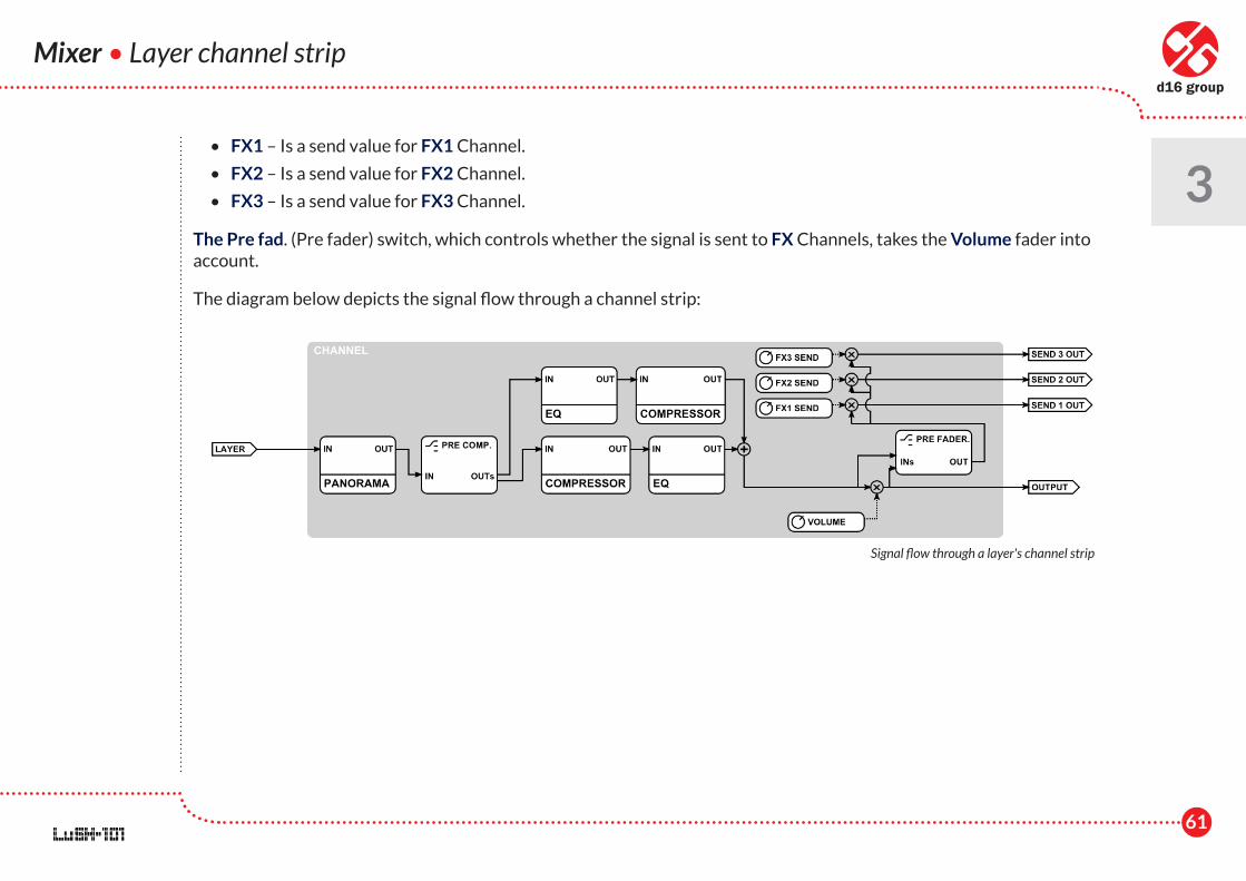
The diagram below depicts the signal flow through a channel strip:
Mixer • Layer channel strip
3
Signal flow through a layer's channel strip
62
Mixer • FX Channel strip
3FX Channel strip
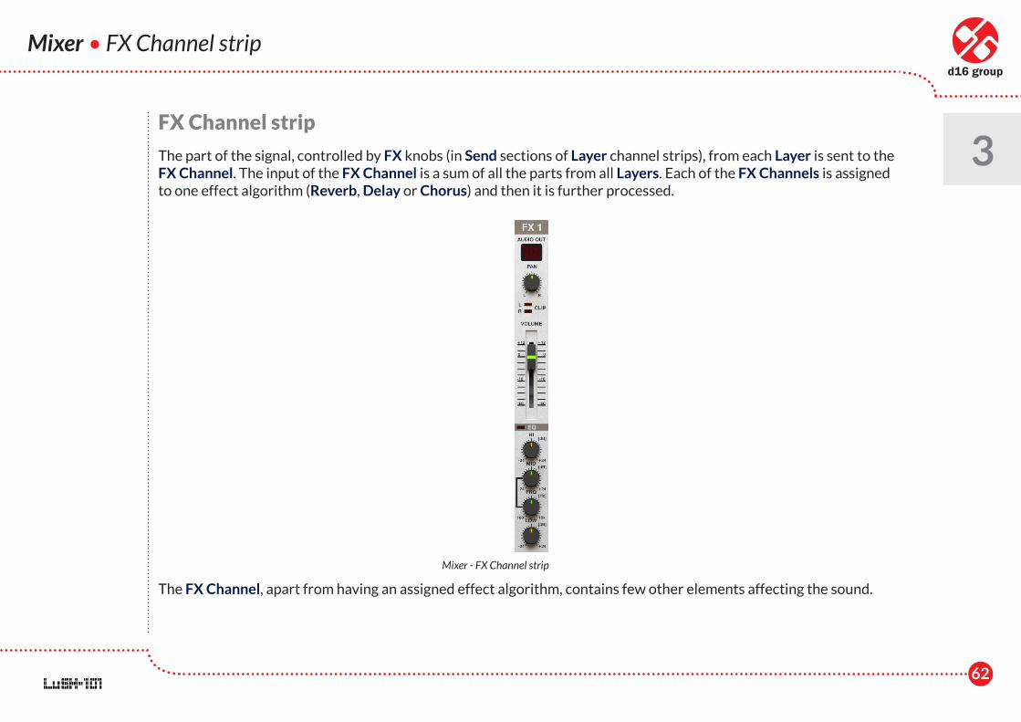
The part of the signal, controlled by FX knobs (in Send sections of Layer channel strips), from each Layer is sent to the FX Channel. The input of the FX Channel is a sum of all the parts from all Layers. Each of the FX Channels is assigned to one effect algorithm (Reverb, Delay or Chorus) and then it is further processed.
The FX Channel, apart from having an assigned effect algorithm, contains few other elements affecting the sound.
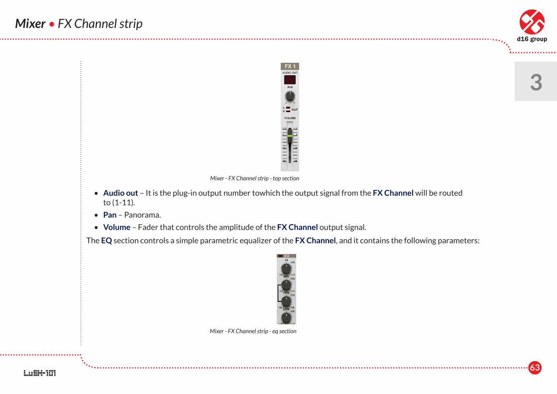
Mixer - FX Channel strip
63
• Audio out – It is the plug-in output number towhich the output signal from the FX Channel will be routed to (1-11).
• Pan – Panorama.
• Volume – Fader that controls the amplitude of the FX Channel output signal.
The EQ section controls a simple parametric equalizer of the FX Channel, and it contains the following parameters:
Mixer • FX Channel strip
3
Mixer - FX Channel strip - top section
Mixer - FX Channel strip - eq section
64
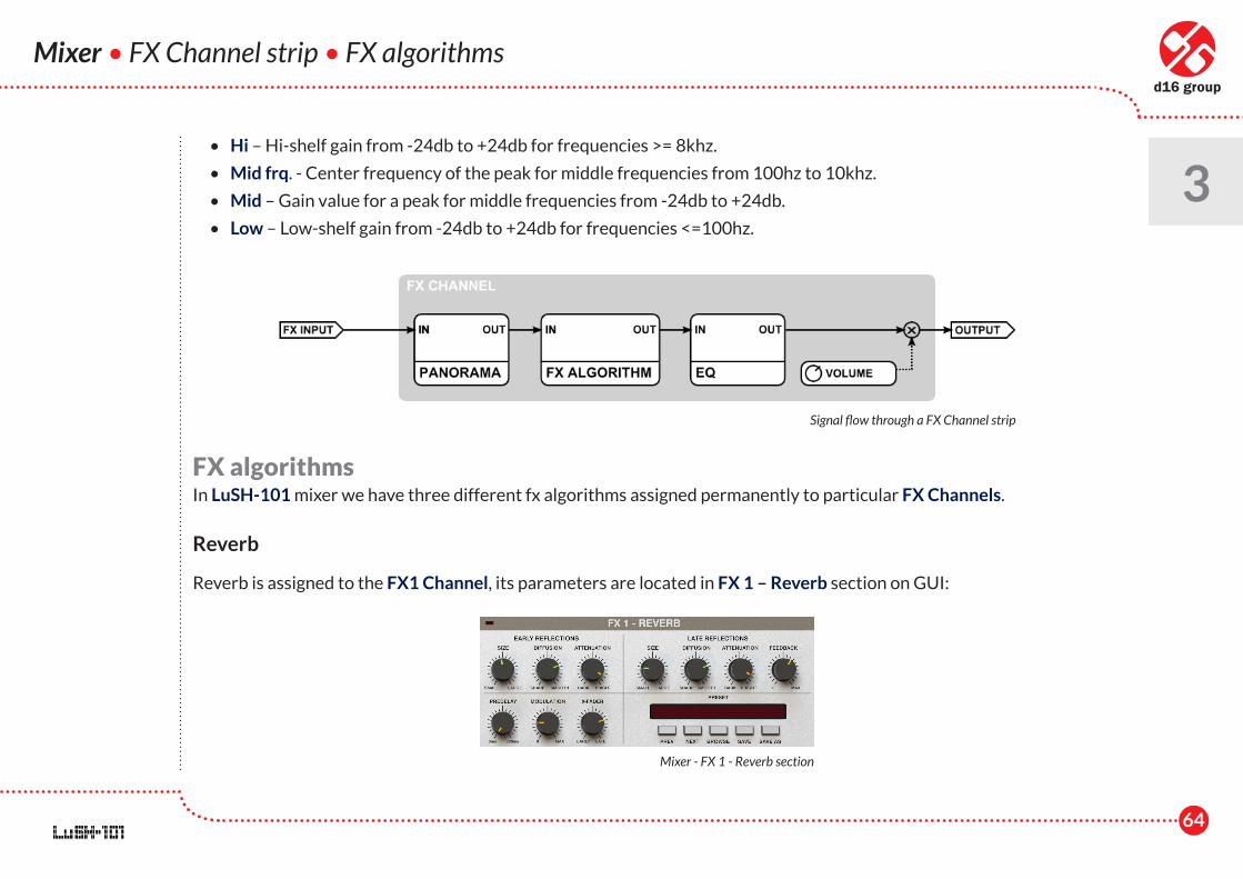
• Hi – Hi-shelf gain from -24db to +24db for frequencies >= 8khz.
• Mid frq. - Center frequency of the peak for middle frequencies from 100hz to 10khz.
• Mid – Gain value for a peak for middle frequencies from -24db to +24db.
• Low – Low-shelf gain from -24db to +24db for frequencies <=100hz.
FX algorithmsIn LuSH-101 mixer we have three different fx algorithms assigned permanently to particular FX Channels.
Reverb
Reverb is assigned to the FX1 Channel, its parameters are located in FX 1 – Reverb section on GUI:
Mixer • FX Channel strip • FX algorithms
3
Signal flow through a FX Channel strip
Mixer - FX 1 - Reverb section
65
Mixer • FX algorithms
3Here we can distinguish the following groups of parameters:
• Early reflections:
• Size – Size of the room for early reflections only.
• Diffusion - It is the reflecting surface’s ability to spread the echo out. If this parameter is set to Sharp, the reflecting surface is perfectly flat and does not distort the reflected wave. In the case of setting this value to Smooth, the reflecting surface distorts wave and spread out into different directions.
• Attenuation - This parameter changes the characteristic of the wall’s surface, its dumping properties.
• Late reflections:
• Size - Size of the room for late reflections only.
• Diffusion.
• Attenuation.
• Feedback - Controls how much of wave energy is consumed every reflection. The smaller the value the more energy is consumed in every reflection, meaning the feedback is weaker.
• Three other parameters:
• Predelay - Delay between dry signal and reverberation.
• Modulation - It isa parameter, which controls the delay lines disturbance.
• X-Fader– Cross-fade between early reflections output and late reflections output.
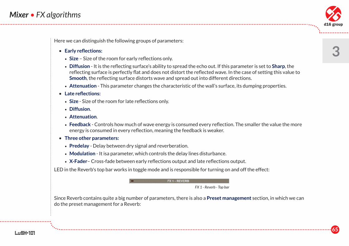
LED in the Reverb's top bar works in toggle mode and is responsible for turning on and off the effect:
Since Reverb contains quite a big number of parameters, there is also a Preset management section, in which we can do the preset management for a Reverb:
FX 1 - Reverb - Top bar
66
Mixer • FX algorithms
3 • The text box containing the name of currently loaded Reverb preset.
• Prev / Next – These two buttons are used for linear navigation through the bank of Reverb presets.
• Browse – This button opens a browser with Reverb presets.
• Save / Save as – Storing a current setting as a preset.
Delay
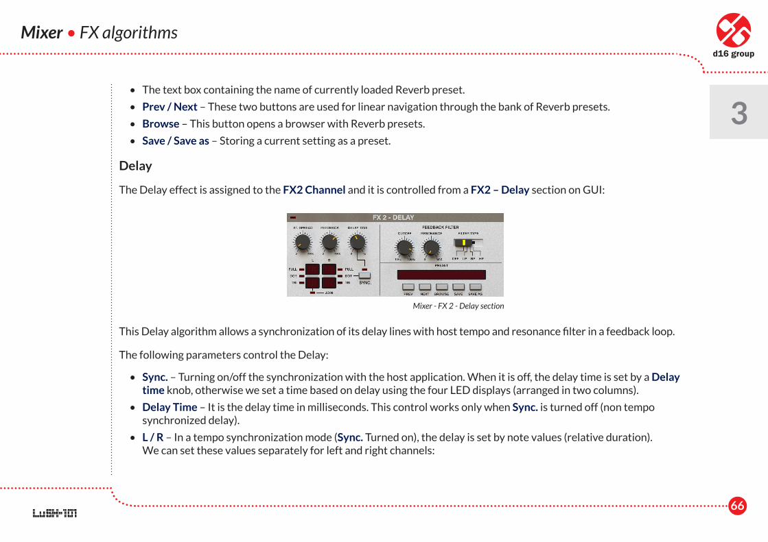
The Delay effect is assigned to the FX2 Channel and it is controlled from a FX2 – Delay section on GUI:
This Delay algorithm allows a synchronization of its delay lines with host tempo and resonance filter in a feedback loop.
The following parameters control the Delay:
• Sync. – Turning on/off the synchronization with the host application. When it is off, the delay time is set by a Delay time knob, otherwise we set a time based on delay using the four LED displays (arranged in two columns).
• Delay Time – It is the delay time in milliseconds. This control works only when Sync. is turned off (non tempo synchronized delay).
• L / R – In a tempo synchronization mode (Sync. Turned on), the delay is set by note values (relative duration). We can set these values separately for left and right channels:
Mixer - FX 2 - Delay section
67
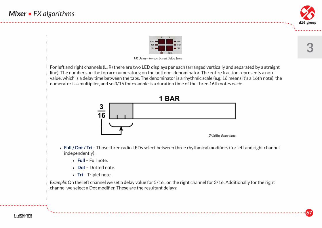
For left and right channels (L, R) there are two LED displays per each (arranged vertically and separated by a straight line). The numbers on the top are numerators; on the bottom - denominator. The entire fraction represents a note value, which is a delay time between the taps. The denominator is a rhythmic scale (e.g. 16 means it's a 16th note), the numerator is a multiplier, and so 3/16 for example is a duration time of the three 16th notes each:
• Full / Dot / Tri – Those three radio LEDs select between three rhythmical modifiers (for left and right channel independently):
• Full – Full note.
• Dot – Dotted note.
• Tri – Triplet note.
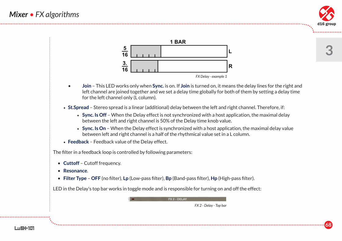
Example: On the left channel we set a delay value for 5/16 , on the right channel for 3/16. Additionally for the right channel we select a Dot modifier. These are the resultant delays:
Mixer • FX algorithms
3FX Delay - tempo based delay time
3/16ths delay time
68
Mixer • FX algorithms
3
• Join – This LED works only when Sync. is on. If Join is turned on, it means the delay lines for the right and left channel are joined together and we set a delay time globally for both of them by setting a delay time for the left channel only (L column).
• St.Spread – Stereo spread is a linear (additional) delay between the left and right channel. Therefore, if:
• Sync. Is Off – When the Delay effect is not synchronized with a host application, the maximal delay between the left and right channel is 50% of the Delay time knob value.
• Sync. Is On – When the Delay effect is synchronized with a host application, the maximal delay value between left and right channel is a half of the rhythmical value set in a L column.
• Feedback – Feedback value of the Delay effect.
The filter in a feedback loop is controlled by following parameters:
• Cuttoff – Cutoff frequency.
• Resonance.
• Filter Type – OFF (no filter), Lp (Low-pass filter), Bp (Band-pass filter), Hp (High-pass filter).
LED in the Delay's top bar works in toggle mode and is responsible for turning on and off the effect:
FX Delay - example 1
FX 2 - Delay - Top bar

69
Mixer • FX algorithms
3The preset section allows for managing the presets for the Delay effect:
• The text box containing the name of the currently loaded Delay's preset.
• Prev / Next – These two buttons are used for linear navigation through the bank of Delay's presets.
• Browse – This button opens a browser for Delay presets.
• Save / Save as – Storing a current setting as a preset.
Chorus
Chorus is an effect permanently assigned to the FX3 Channel, controlled from the FX3 – Chorus section on GUI:
• Rate – Controls LFO frequency [0.01 Hz .. 20 Hz]. The LFO waveform is triangular.
• Depth - Amplitude of LFO oscillations expressed in milliseconds.
• Offset– It is an offset between dry signal and the minimum of the LFO oscillations expressed in milliseconds
• Mode – It isthe volume of the output from the second delay line. It makes the sound more fat.
• Stereo – This is a stereo phase offset of the LFO controlling the delay line.
• HiPass – It is a high-pass filter cutoff frequency. It filters an output signal from the Chorus.
LED in a Chorus' top bar works in toggle mode and is responsible for turning on and off the effect:
Mixer - FX 3 - Chorus section
FX 3 - Chorus - Top bar
70
Mixer • Global preset settings
3Global preset settings
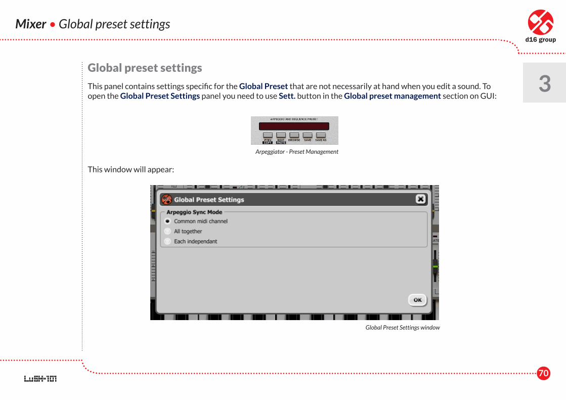
This panel contains settings specific for the Global Preset that are not necessarily at hand when you edit a sound. To open the Global Preset Settings panel you need to use Sett. button in the Global preset management section on GUI:
This window will appear:
Arpeggiator - Preset Management
Global Preset Settings window
71
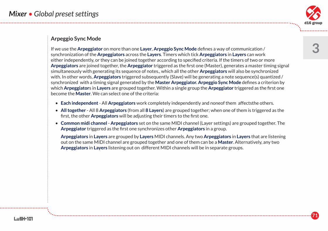
Arpeggio Sync Mode
If we use the Arpeggiator on more than one Layer, Arpeggio Sync Mode defines a way of communication / synchronization of the Arpeggiators across the Layers. Timers which tick Arpeggiators in Layers can work either independently, or they can be joined together according to specified criteria. If the timers of two or more Arpeggiators are joined together, the Arpeggiator triggered as the first one (Master), generates a master timing signal simultaneously with generating its sequence of notes., which all the other Arpeggiators will also be synchronized with. In other words, Arpeggiators triggered subsequently (Slave) will be generating a note sequence(s) quantized / synchronized with a timing signal generated by the Master Arpeggiator. Arpeggio Sync Mode defines a criterion by which Arpeggiators in Layers are grouped together. Within a single group the Arpeggiator triggered as the first one become the Master. We can select one of the criteria:
• Each independent - All Arpeggiators work completely independently and noneof them affectsthe others.
• All together - All 8 Arpeggiators (from all 8 Layers) are grouped together; when one of them is triggered as the first, the other Arpeggiators will be adjusting their timers to the first one.
• Common midi channel - Arpeggiators set on the same MIDI channel (Layer settings) are grouped together. The Arpeggiator triggered as the first one synchronizes other Arpeggiators in a group.
Arpeggiators in Layers are grouped by Layers MIDI channels. Any two Arpeggiators in Layers that are listening out on the same MIDI channel are grouped together and one of them can be a Master. Alternatively, any two Arpeggiators in Layers listening out on different MIDI channels will be in separate groups.
Mixer • Global preset settings
3
72
Preset Management • Preset structure
4Preset Management
Presets structure
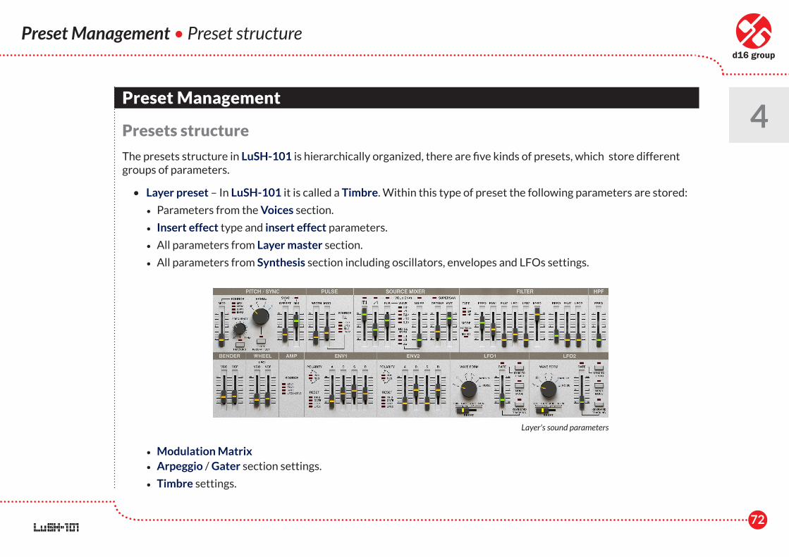
The presets structure in LuSH-101 is hierarchically organized, there are five kinds of presets, which store different groups of parameters.
• Layer preset – In LuSH-101 it is called a Timbre. Within this type of preset the following parameters are stored:
• Parameters from the Voices section.
• Insert effect type and insert effect parameters.
• All parameters from Layer master section.
• All parameters from Synthesis section including oscillators, envelopes and LFOs settings.
• Modulation Matrix • Arpeggio / Gater section settings.
• Timbre settings.
Layer's sound parameters
73
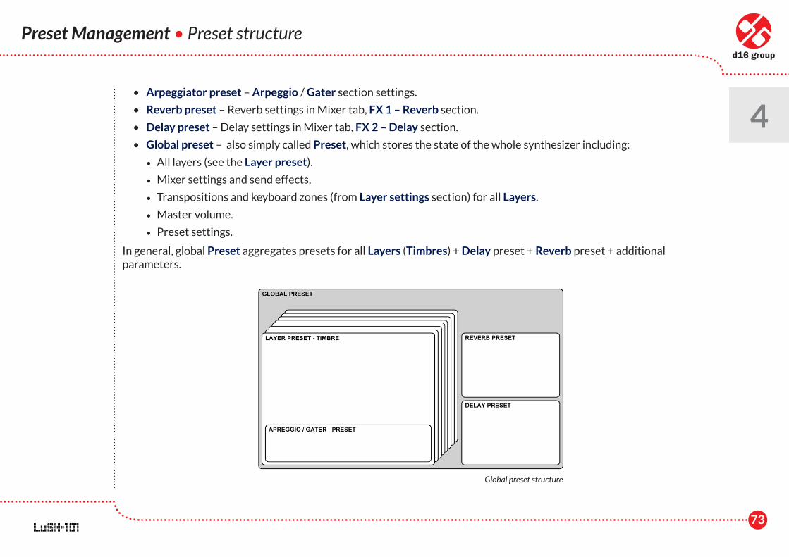
• Arpeggiator preset – Arpeggio / Gater section settings.
• Reverb preset – Reverb settings in Mixer tab, FX 1 – Reverb section.
• Delay preset – Delay settings in Mixer tab, FX 2 – Delay section.
• Global preset – also simply called Preset, which stores the state of the whole synthesizer including:
• All layers (see the Layer preset).
• Mixer settings and send effects,
• Transpositions and keyboard zones (from Layer settings section) for all Layers.
• Master volume.
• Preset settings.
In general, global Preset aggregates presets for all Layers (Timbres) + Delay preset + Reverb preset + additional parameters.
Preset Management • Preset structure
4
Global preset structure
74
Preset Management • Preset storage
4Preset storage
All kinds of presets are stored on a disk in a particular location, which makes the process of management smooth and allows to easily exchange presets between users. When you insert a plug-in to a host application, before the window opens, some initial actions are performed. Among those, LuSH-101 scans the location in which presets are stored on the hard disk and projects this location into the tree (hierarchical) structure, which corresponds to a structure of folders and files:
• Single files are projected as presets and the file name is the preset name.
• A folder is projected as a group of presets, which is presented in the Preset Browser as a group (node). It is allowed to nest the structure of groups and single presets into another group etc.
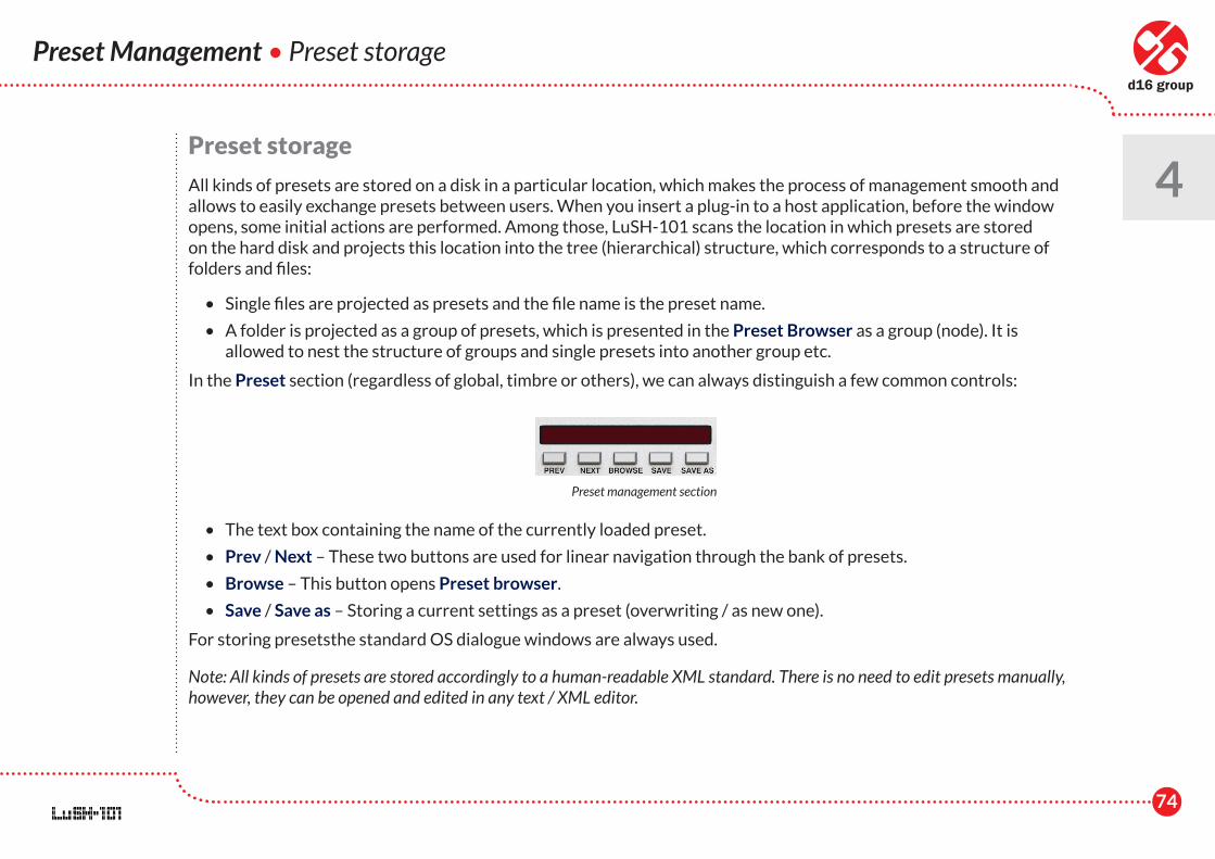
In the Preset section (regardless of global, timbre or others), we can always distinguish a few common controls:
• The text box containing the name of the currently loaded preset.
• Prev / Next – These two buttons are used for linear navigation through the bank of presets.
• Browse – This button opens Preset browser.
• Save / Save as – Storing a current settings as a preset (overwriting / as new one).
For storing presetsthe standard OS dialogue windows are always used.
Note: All kinds of presets are stored accordingly to a human-readable XML standard. There is no need to edit presets manually, however, they can be opened and edited in any text / XML editor.
Preset management section
75
By default, presets are kept on the hard drive:
• for MacOS – the folder “~/Library/Application Support/D16 Group/LuSH-101/Arpe”
• for Windows – the folder "c:\Users\[user_name]\AppData\Roaming\D16 Group\LuSH-101"
Following files types are recognized by LuSH-101:
• .shprst - Global Preset,
• .shtmbr - Timbre (Layer) Preset,
• .shfx1 - Reverb effect's Preset
• .shfx2 - Delay effect's Preset
• .sharpe - Arpeggiator's Preset
Padlocks
Padlock is a functionality, which makes locking a certain set of parameters when the preset is loaded possible; values of the locked parameters will not be altered. There are two kinds of Padlocks in LuSH-101 considering the range of effect:
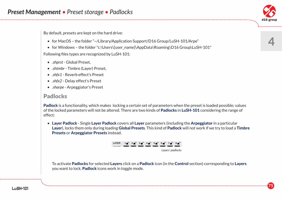
• Layer Padlock - Single Layer Padlock covers all Layer parameters (including the Arpeggiator in a particular Layer), locks them only during loading Global Presets. This kind of Padlock will not work if we try to load a Timbre Presets or Arpeggiator Presets instead.
To activate Padlocks for selected Layers click on a Padlock icon (in the Control section) corresponding to Layers you want to lock. Padlock icons work in toggle mode.
Preset Management • Preset storage • Padlocks
4
Layers' padlocks
76
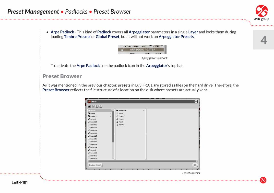
• Arpe Padlock - This kind of Padlock covers all Arpeggiator parameters in a single Layer and locks them during loading Timbre Presets or Global Preset, but it will not work on Arpeggiator Presets.
To activate the Arpe Padlock use the padlock icon in the Arpeggiator's top bar.
Preset Browser
As it was mentioned in the previous chapter, presets in LuSH-101 are stored as files on the hard drive. Therefore, the Preset Browser reflects the file structure of a location on the disk where presets are actually kept.
Preset Management • Padlocks • Preset Browser
4Apreggiator's padlock
Preset Browser
77
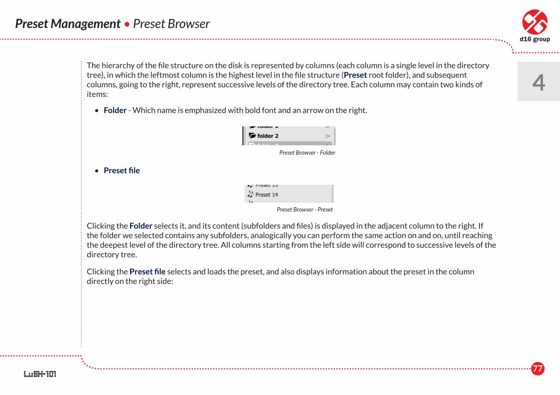
The hierarchy of the file structure on the disk is represented by columns (each column is a single level in the directory tree), in which the leftmost column is the highest level in the file structure (Preset root folder), and subsequent columns, going to the right, represent successive levels of the directory tree. Each column may contain two kinds of items:
• Folder - Which name is emphasized with bold font and an arrow on the right.
• Preset file
Clicking the Folder selects it, and its content (subfolders and files) is displayed in the adjacent column to the right. If the folder we selected contains any subfolders, analogically you can perform the same action on and on, until reaching the deepest level of the directory tree. All columns starting from the left side will correspond to successive levels of the directory tree.
Clicking the Preset file selects and loads the preset, and also displays information about the preset in the column directly on the right side:
Preset Management • Preset Browser
4
Preset Browser - Folder
Preset Browser - Preset
78
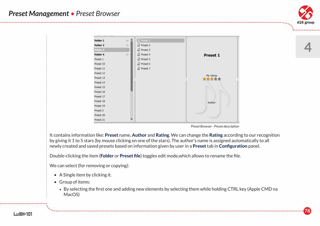
It contains information like: Preset name, Author and Rating. We can change the Rating according to our recognition by giving it 1 to 5 stars (by mouse clicking on one of the stars). The author's name is assigned automatically to all newly created and saved presets based on information given by user in a Preset tab in Configuration panel.
Double-clicking the item (Folder or Preset file) toggles edit mode,which allows to rename the file.
We can select (for removing or copying):
• A Single item by clicking it.
• Group of items:
• By selecting the first one and adding new elements by selecting them while holding CTRL key (Apple CMD na MacOS)
Preset Management • Preset Browser
4
Preset Browser - Preset description
79
Preset Management • Preset Browser
4 • By selecting a range of items; click the first one (to mark the beginning) and then click the last one while holding
CTRL key (to mark an end).
Selected item(s) can be moved to any subfolder using the drag'n'drop method. It is also possible to move a selected Preset / Folder or group level up in the directory tree using the drag'n'drop method, if we drop the selected item(s) onto the column on the right.
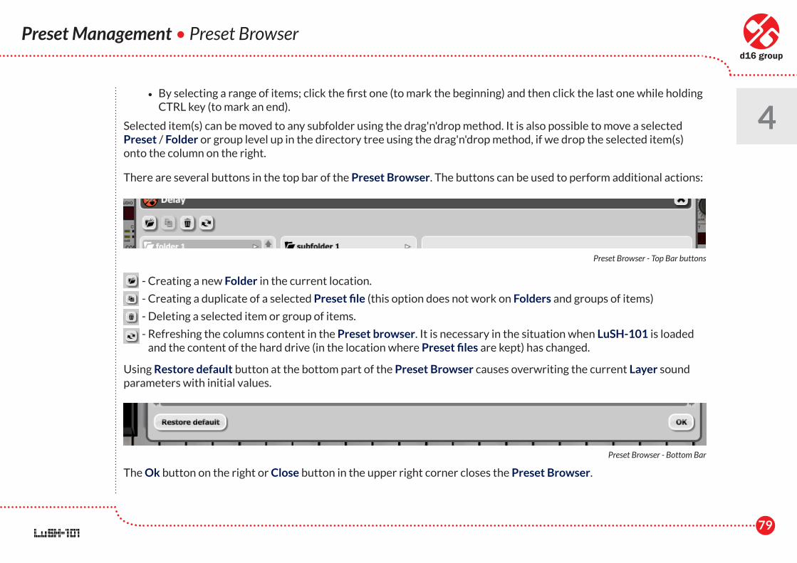
There are several buttons in the top bar of the Preset Browser. The buttons can be used to perform additional actions:
- Creating a new Folder in the current location.
- Creating a duplicate of a selected Preset file (this option does not work on Folders and groups of items)
- Deleting a selected item or group of items.
- Refreshing the columns content in the Preset browser. It is necessary in the situation when LuSH-101 is loaded and the content of the hard drive (in the location where Preset files are kept) has changed.
Using Restore default button at the bottom part of the Preset Browser causes overwriting the current Layer sound parameters with initial values.
The Ok button on the right or Close button in the upper right corner closes the Preset Browser.
Preset Browser - Top Bar buttons
Preset Browser - Bottom Bar
80
Preset Management • Preset Browser
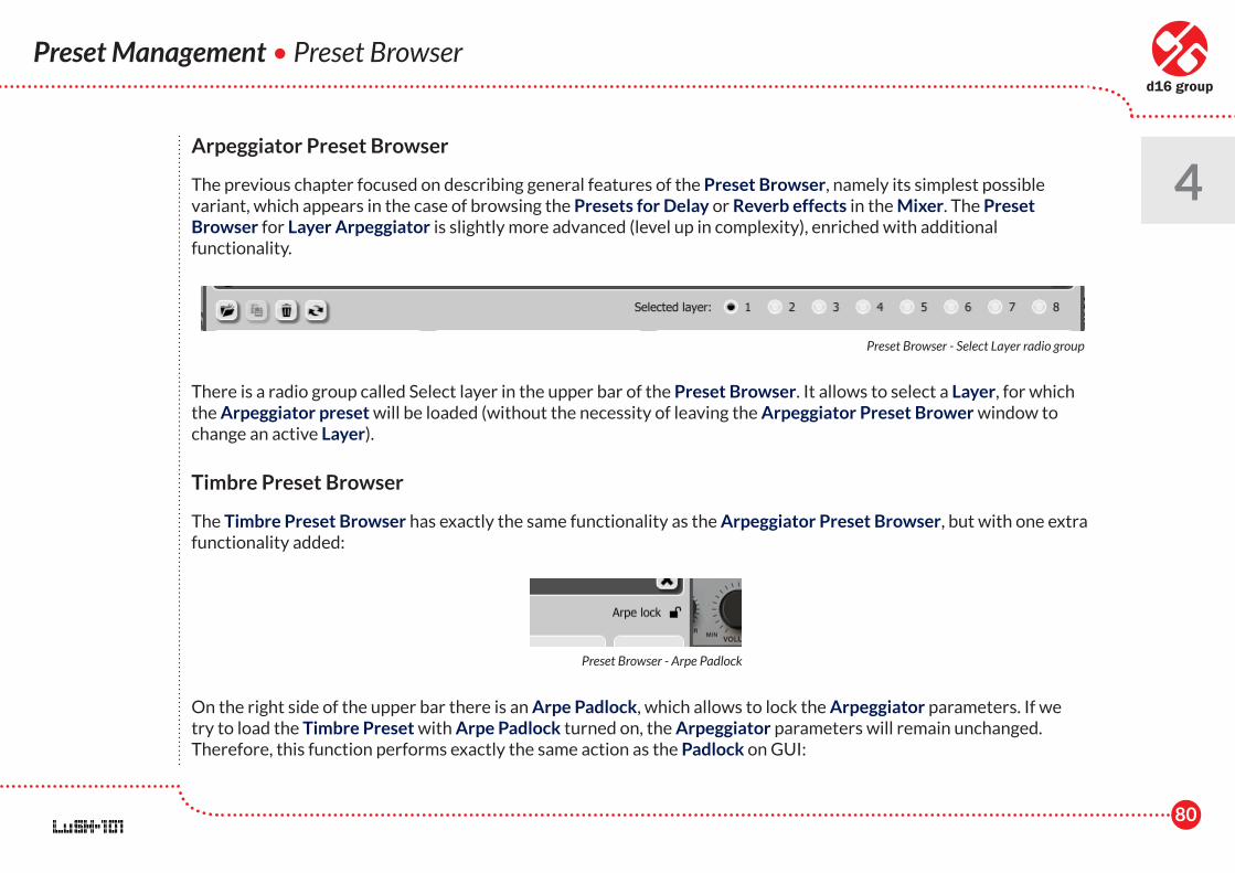
4Arpeggiator Preset Browser
The previous chapter focused on describing general features of the Preset Browser, namely its simplest possible variant, which appears in the case of browsing the Presets for Delay or Reverb effects in the Mixer. The Preset Browser for Layer Arpeggiator is slightly more advanced (level up in complexity), enriched with additional functionality.
There is a radio group called Select layer in the upper bar of the Preset Browser. It allows to select a Layer, for which the Arpeggiator preset will be loaded (without the necessity of leaving the Arpeggiator Preset Brower window to change an active Layer).
Timbre Preset Browser
The Timbre Preset Browser has exactly the same functionality as the Arpeggiator Preset Browser, but with one extra functionality added:
On the right side of the upper bar there is an Arpe Padlock, which allows to lock the Arpeggiator parameters. If we try to load the Timbre Preset with Arpe Padlock turned on, the Arpeggiator parameters will remain unchanged. Therefore, this function performs exactly the same action as the Padlock on GUI:
Preset Browser - Select Layer radio group
Preset Browser - Arpe Padlock
81
Preset Management • Preset Browser
4We do not have to leave the Timbre Preset Browser to toggle it.
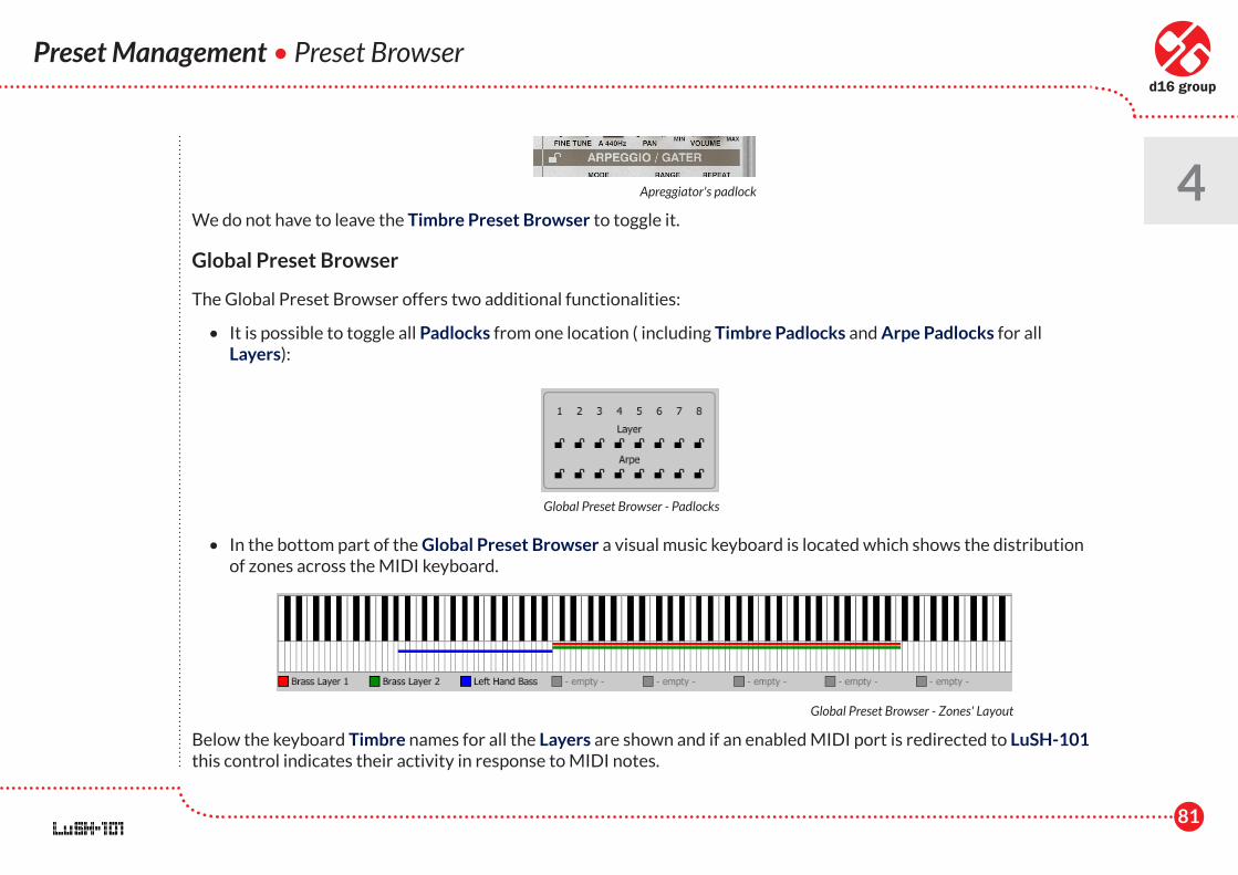
Global Preset Browser
The Global Preset Browser offers two additional functionalities:
• It is possible to toggle all Padlocks from one location ( including Timbre Padlocks and Arpe Padlocks for all Layers):
• In the bottom part of the Global Preset Browser a visual music keyboard is located which shows the distribution of zones across the MIDI keyboard.
Below the keyboard Timbre names for all the Layers are shown and if an enabled MIDI port is redirected to LuSH-101 this control indicates their activity in response to MIDI notes.
Apreggiator's padlock
Global Preset Browser - Padlocks
Global Preset Browser - Zones' Layout
82
Configuration
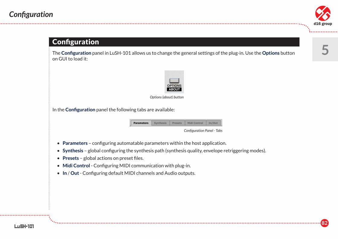
5Configuration
The Configuration panel in LuSH-101 allows us to change the general settings of the plug-in. Use the Options button on GUI to load it:
In the Configuration panel the following tabs are available:
• Parameters – configuring automatable parameters within the host application.
• Synthesis – global configuring the synthesis path (synthesis quality, envelope retriggering modes).
• Presets – global actions on preset files.
• Midi Control - Configuring MIDI communication with plug-in.
• In / Out - Configuring default MIDI channels and Audio outputs.
Options (about) button
Configuration Panel - Tabs
83
Configuration • Parameters
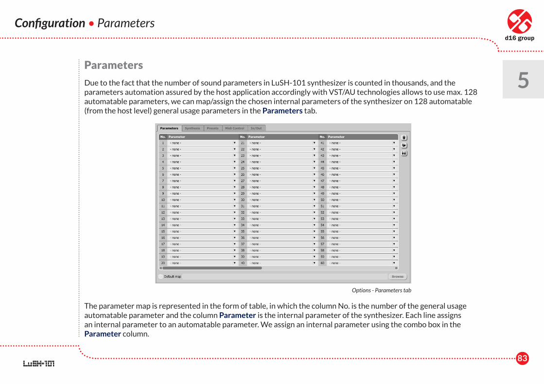
5Parameters
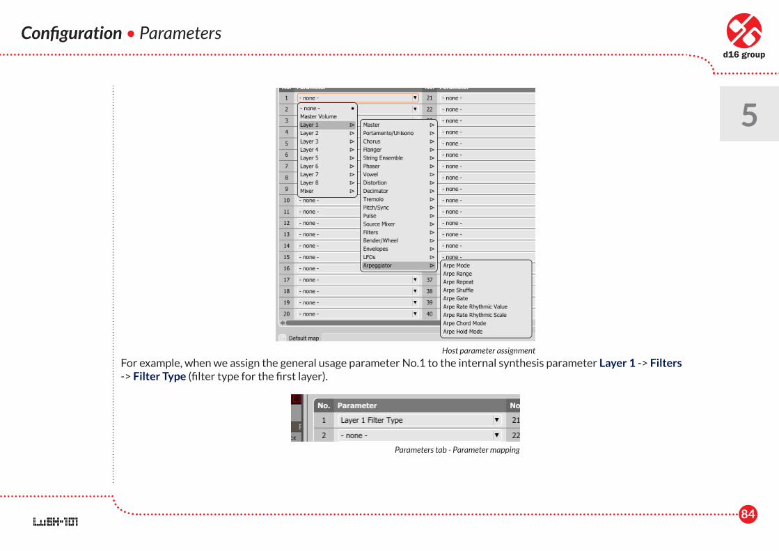
Due to the fact that the number of sound parameters in LuSH-101 synthesizer is counted in thousands, and the parameters automation assured by the host application accordingly with VST/AU technologies allows to use max. 128 automatable parameters, we can map/assign the chosen internal parameters of the synthesizer on 128 automatable (from the host level) general usage parameters in the Parameters tab.
The parameter map is represented in the form of table, in which the column No. is the number of the general usage automatable parameter and the column Parameter is the internal parameter of the synthesizer. Each line assigns an internal parameter to an automatable parameter. We assign an internal parameter using the combo box in the Parameter column.
Options - Parameters tab
84
Configuration • Parameters
5
For example, when we assign the general usage parameter No.1 to the internal synthesis parameter Layer 1 -> Filters -> Filter Type (filter type for the first layer).
Host parameter assignment
Parameters tab - Parameter mapping
85
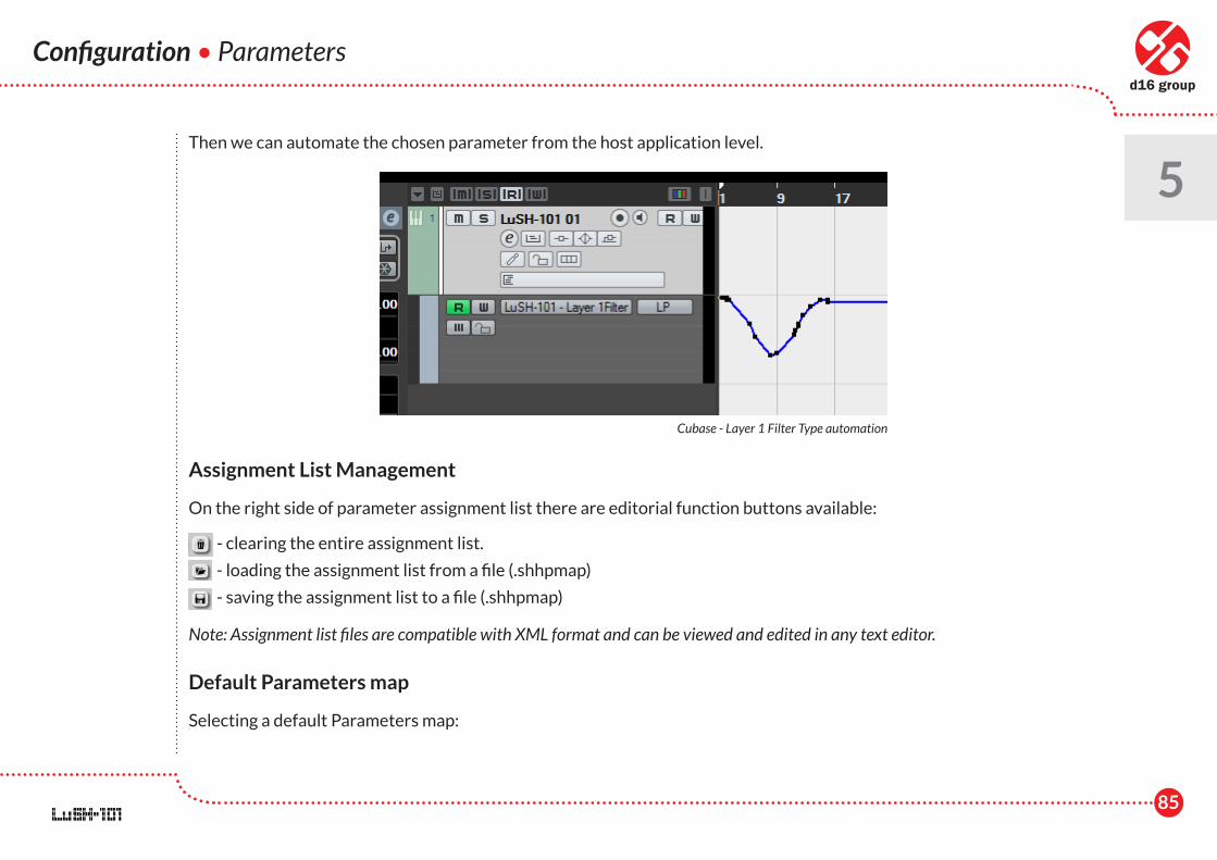
Then we can automate the chosen parameter from the host application level.
Assignment List Management
On the right side of parameter assignment list there are editorial function buttons available:
- clearing the entire assignment list.
- loading the assignment list from a file (.shhpmap)
- saving the assignment list to a file (.shhpmap)
Note: Assignment list files are compatible with XML format and can be viewed and edited in any text editor.
Default Parameters map
Selecting a default Parameters map:
Configuration • Parameters
5
Cubase - Layer 1 Filter Type automation
86
Configuration • Parameters • Midi Control tab
5 1. Check the Default Map checkbox, which activates the Browse button on the right.
2. Click the Browse and select a file with saved Parameters map.
After selecting a Parameters map the text box on the left from the Browse button shows the path to the active map file. A default Parameters map is loaded each time when the plug-ins is loaded.
Midi Control tab
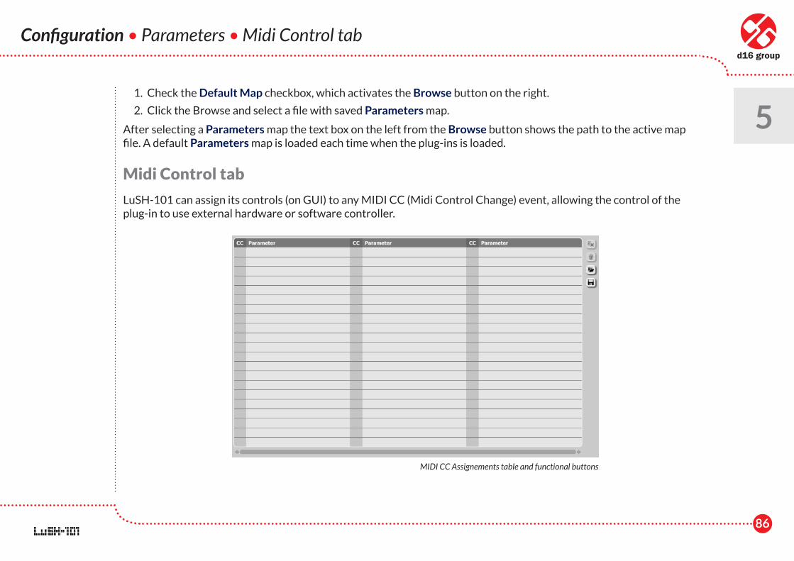
LuSH-101 can assign its controls (on GUI) to any MIDI CC (Midi Control Change) event, allowing the control of the plug-in to use external hardware or software controller.
MIDI CC Assignements table and functional buttons
87
Controls included in the tab:
• Midi learn mode - Checkbox which activates Midi learn mode.
• List of active MIDI CC assignments - containing pairs consisting of MIDI CC number and the name of the plug-in parameter.
• Default Map - Checkbox which activates a default MIDI CC map. When the map is activated it will be loaded with creating a new instance of the plug-in.
Midi learn
Assigning a LuSH-101' control to the MIDI controller requires:
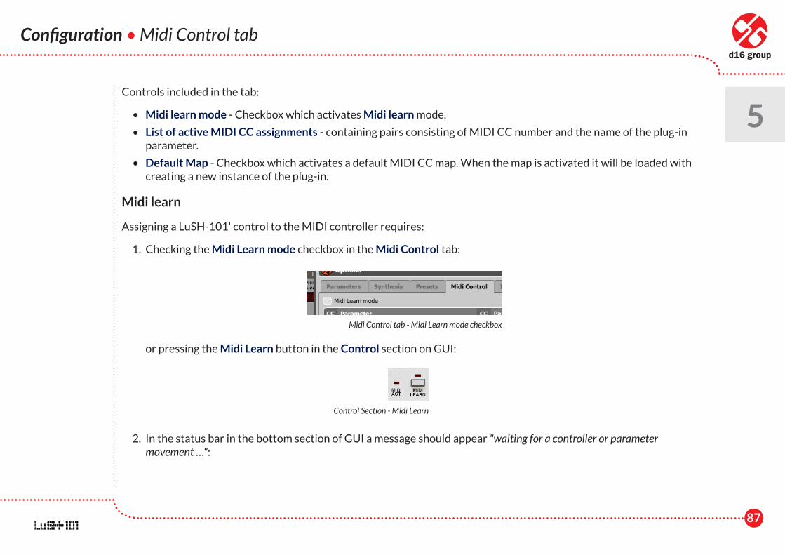
1. Checking the Midi Learn mode checkbox in the Midi Control tab:
or pressing the Midi Learn button in the Control section on GUI:
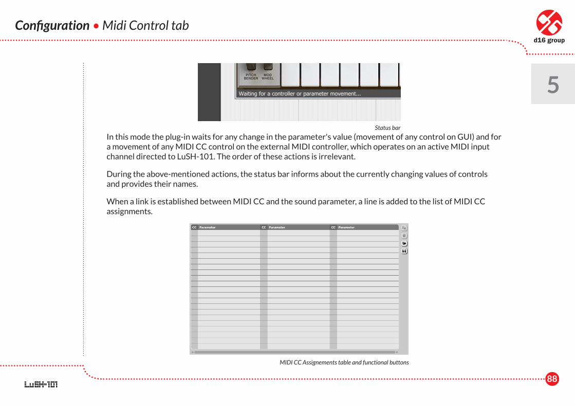
2. In the status bar in the bottom section of GUI a message should appear "waiting for a controller or parameter movement …":
Configuration • Midi Control tab
5
Midi Control tab - Midi Learn mode checkbox
Control Section - Midi Learn
88
Configuration • Midi Control tab
5
In this mode the plug-in waits for any change in the parameter's value (movement of any control on GUI) and for a movement of any MIDI CC control on the external MIDI controller, which operates on an active MIDI input channel directed to LuSH-101. The order of these actions is irrelevant.
During the above-mentioned actions, the status bar informs about the currently changing values of controls and provides their names.
When a link is established between MIDI CC and the sound parameter, a line is added to the list of MIDI CC assignments.
Status bar
MIDI CC Assignements table and functional buttons
89
Configuration • Midi Control tab
5 When a link is established for a controller, it is possible to repeat the operation for next MIDI CC and parameter
pairs. Subsequent links will be created and added to the list.
3. When all the needed links are created, uncheck the Midi Learn Mode checkbox or press again the Midi Learn button on GUI in the Control section.
In order to create new links, it is possible to reactivate the Midi Learn mode at any time.
The links are always sorted in an ascending manner in relation to the CC column (according to the MIDI CC code).
Unlinking and MIDI link management
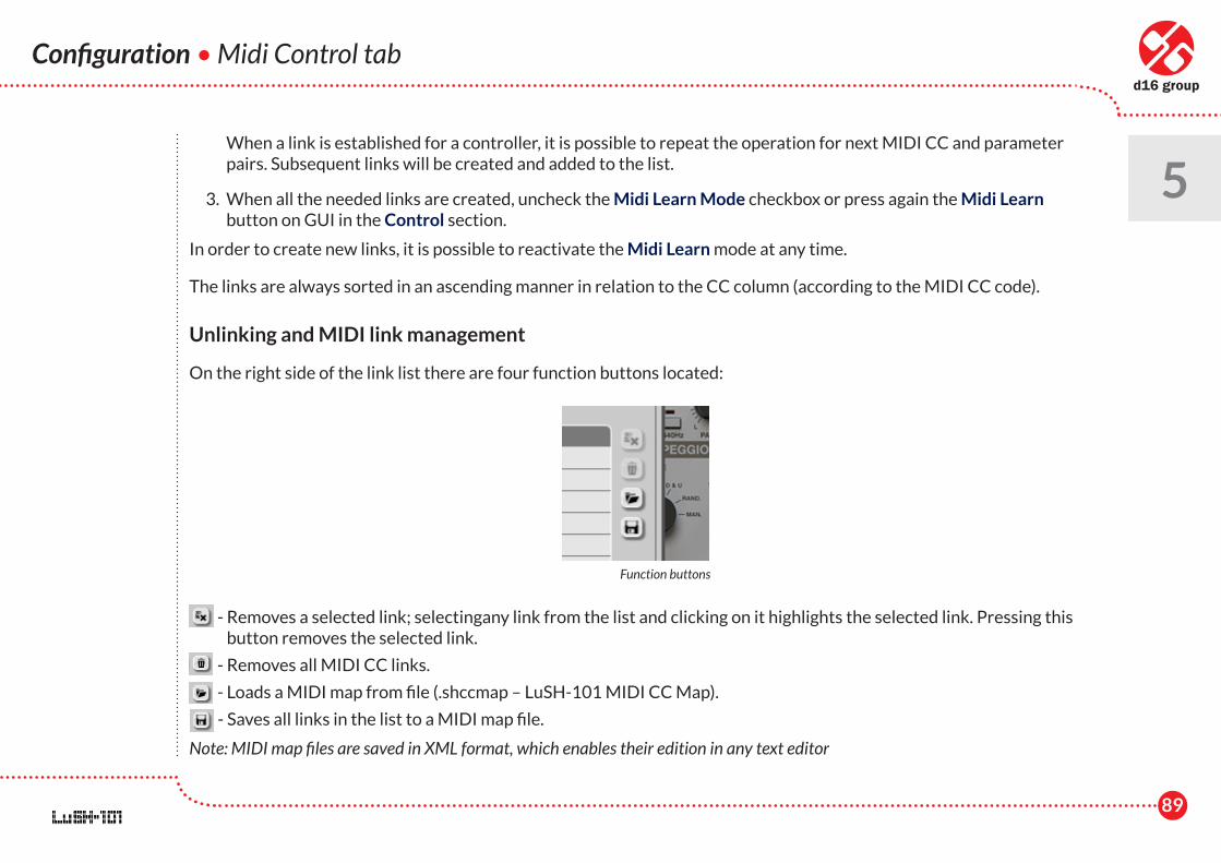
On the right side of the link list there are four function buttons located:
- Removes a selected link; selectingany link from the list and clicking on it highlights the selected link. Pressing this button removes the selected link.
- Removes all MIDI CC links.
- Loads a MIDI map from file (.shccmap – LuSH-101 MIDI CC Map).
- Saves all links in the list to a MIDI map file.
Note: MIDI map files are saved in XML format, which enables their edition in any text editor
Function buttons
90
Configuration • Midi Control tab • Synthesis
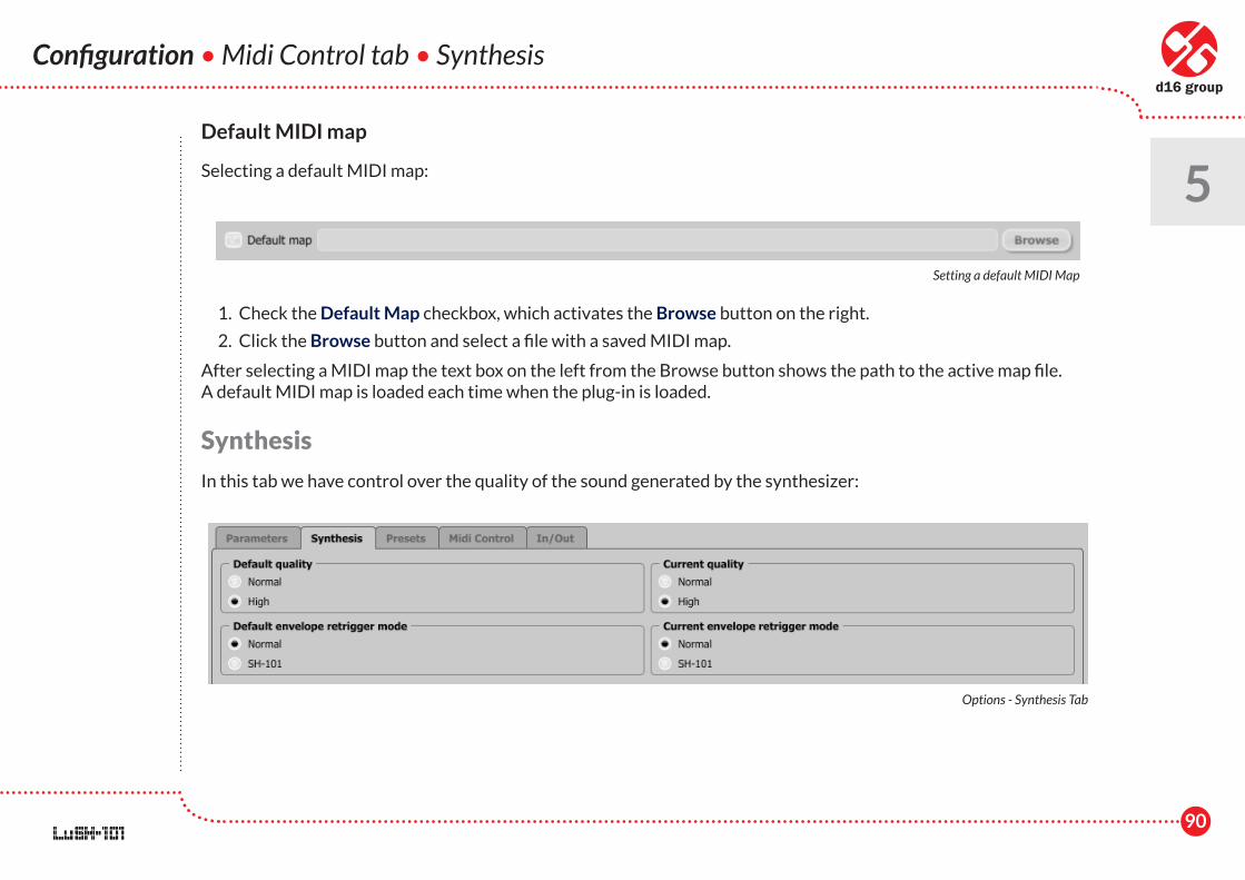
5Default MIDI map
Selecting a default MIDI map:
1. Check the Default Map checkbox, which activates the Browse button on the right.
2. Click the Browse button and select a file with a saved MIDI map.
After selecting a MIDI map the text box on the left from the Browse button shows the path to the active map file. A default MIDI map is loaded each time when the plug-in is loaded.
Synthesis
In this tab we have control over the quality of the sound generated by the synthesizer:
Setting a default MIDI Map
Options - Synthesis Tab
91
Current Quality
Allows to select the current quality. We can choose from two available grades:
• Normal
• High
High quality chosen, requires more CPU resources. Changing the Current Quality instantly affects the generated sound. Keep in mind that the tone of a sound can be slightly different when we change this setting.
Current Quality is stored within the host project file.
Default Quality
Every time a LuSH-101 is loaded in the host application (new instance is created) the Default Quality value is used for a Current Quality setting. Default Quality is stored within a configuration file of LuSH-101. This file is saved at the moment of unloading any of active plug-in instances from the host application.
Default envelope retrigger mode
Allows to switch the envelope retrigger mode within polyphony = 1 voice (monophony) and within the set envelope reset mode on Trig.
• Normal – When by using the MIDI keyboard we trigger sounds and hold them, then in every new MIDI note the envelope is reset despite the fact that the earlier pressed notes were held. This is characteristic for the Trig reset mode. Remember, when polyphony = 1 voice, only one note is always played from all the note notes pressed on the keyboard. When we release the key responsible for playing the note, one of the earlier pressed notes will be played. However, when we choose Normal mode (default for the Default Envelope Retrigger mode), releasing a button does not result in resetting the envelope.
Configuration • Synthesis
5
92
• SH-101 – This envelope retrigger mode was inspired by the manner in which the envelope was working in SH-101 synthesizer and it differs from Normal mode in one aspect. When successively releasing the pressed keys on the MDI keyboard, not only does the played note change, but the envelope is also reset if it is switched to Trig reset mode.
Default envelope retrigger mode
Every time a LuSH-101 is loaded in host application (new instance is created) the Default Quality's value is used for a Current Quality setting. Default Quality is stored within a configuration file of the LuSH-101. This file is saved in a moment of unloading any of active plug-in instances from the host application.
Presets
In the Presets tab, we have an access to functions allowing certain global actions on preset file.
Every preset in LuSH-101 apart from storing the values of sound parameters, stores also certain additional information i.e. author’s name or rating. The Author box in the Presets tab, describes the author’s name which is going to be saved within every new instance of the preset. Double-click and edit the box, confirm with enter button to change the value of the box. Any new instance of the preset (Global, Timbre or one of the send effects) is going to encompass information from that box.
Update presets button updates information about the author in every new instance of the preset created by the user. Other presets, e.g. default presets, presets of other authors, will not be modified.
The Presets directory value below the Author box displays the path to the present bank on the hard drive.
In / Out
Allows to modify the default MIDI input channels and / or Audio outputs routing.
Configuration • Synthesis • Presets • In / Out
5
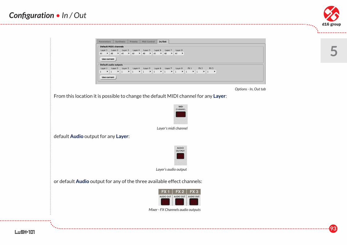
93
Configuration • In / Out
5
From this location it is possible to change the default MIDI channel for any Layer:
default Audio output for any Layer:
or default Audio output for any of the three available effect channels:
Options - In, Out tab
Layer's midi channel
Layer's audio output
Mixer - FX Channels audio outputs
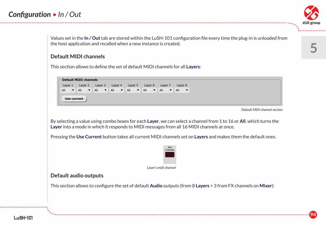
94
Configuration • In / Out
5Values set in the In / Out tab are stored within the LuSH-101 configuration file every time the plug-in is unloaded from the host application and recalled when a new instance is created.
Default MIDI channels
This section allows to define the set of default MIDI channels for all Layers:
By selecting a value using combo boxes for each Layer, we can select a channel from 1 to 16 or All, which turns the Layer into a mode in which it responds to MIDI messages from all 16 MIDI channels at once.
Pressing the Use Current button takes all current MIDI channels set on Layers and makes them the default ones.
Default audio outputs
This section allows to configure the set of default Audio outputs (from 8 Layers + 3 from FX channels on Mixer):
Default MIDI channel section
Layer's midi channel
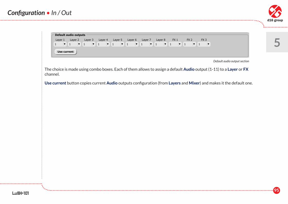
95
Configuration • In / Out
5
The choice is made using combo boxes. Each of them allows to assign a default Audio output (1-11) to a Layer or FX channel.
Use current button copies current Audio outputs configuration (from Layers and Mixer) and makes it the default one.
Default audio output section

96
Contents
6Contents
1 Overview .............................................................................. 1
2 Layer ...................................................................................... 5
Layer settings .................................................................. 8
Synthesis ........................................................................... 14
Oscillators - VCO ...................................................... 14
HardSync ...................................................................... 17
Supersaw ....................................................................... 18
Pulse Width Modulation – PWM ........................ 19
Envelope generators ................................................ 19
Low Frequency Oscillators - LFO ........................ 22
Filters .............................................................................. 24
Oscillator's frequency control .............................. 27
Amplifier - VCA ........................................................... 29
Wheel and Bender modulation ............................ 30
Master section ............................................................ 32
Insert effects ................................................................... 33
Chorus ........................................................................... 34
Flanger .......................................................................... 34
String ensemble .......................................................... 35
Phaser............................................................................. 36
Vowel filter ................................................................... 36
Distortion...................................................................... 37
Decimator ..................................................................... 37
Tremolo .......................................................................... 38
Arpeggiator ...................................................................... 39
Examples ....................................................................... 42
Modulation Matrix ........................................................ 46
Voice Volume - A special destination parameter ..................................................................... 50
Arpe Gate, Arpe Tie - special modulation sources ........................................................................... 50
Timbre Preset Settings ................................................ 52
3 Mixer ...................................................................................... 55
Layer channel strip ....................................................... 58
FX Channel strip ............................................................ 62
97
Contents
6 FX algorithms .................................................................. 64
Reverb ............................................................................ 64
Delay ............................................................................... 66
Chorus ............................................................................ 69
Global preset settings .................................................. 70
Arpeggio Sync Mode ................................................ 71
4 Preset Management ........................................................ 72
Presets structure ........................................................... 72
Preset storage ................................................................ 74
Padlocks ............................................................................ 75
Preset Browser .............................................................. 76
Arpeggiator Preset Browser ................................ 80
Timbre Preset Browser .......................................... 80
Global Preset Browser ........................................... 81
Default Presets .......................................................... 80
5 Configuration ...................................................................... 82
Parameters ....................................................................... 83
Assignment List Management .............................. 85
Default Parameters map ......................................... 85
Midi Control tab ............................................................. 86
Midi learn ...................................................................... 87
Unlinking and MIDI link management............... 89
Default MIDI map ...................................................... 90
Synthesis ............................................................................ 90
Current Quality .......................................................... 91
Default Quality ........................................................... 91
Default envelope retrigger mode ........................ 91
Presets ................................................................................ 92
In / Out ............................................................................... 92
Default MIDI channels ............................................ 94
Default audio outputs .............................................. 94
6 Contents ............................................................................... 96