lte tutorial femtoforum part1
DESCRIPTION
lteTRANSCRIPT

1Marius Pesavento, Willem Mulder, Femto Forum Plenary, June 2010, Reading, UK © mimoOn
LTE Tutorial part 1LTE Basics
Marius Pesavento - [email protected] Mulder - [email protected]

2Marius Pesavento, Willem Mulder, Femto Forum Plenary, June 2010, Reading, UK © mimoOn
Agenda
Part 1, LTE Basics 9:30 – 10:30 Introduction to LTE FDD/TDD frame structures and reference signals Physical channels, logical channels PHY signal processing architecture H-ARQ processing, H-ARQ timing UE categories
Part 2, Advanced topics in LTE 11:00 – 12:30 The LTE MIMO modes Codebook-based precoding Closed loop operation CQI reporting modes Using antenna port 5 (SDMA) techniques Simulation results Outlook LTE Advanced
Q & A 12:30 – 13:00

3Marius Pesavento, Willem Mulder, Femto Forum Plenary, June 2010, Reading, UK © mimoOn
3G Evolution
HSPA evolution Gradually improved performance at low additional cost in 5MHz spectrum
allocation Next step: dual carrier allocation (10MHz)
LTE LTE is new Radio Access Network (RAN) significantly improved performance in up to 20MHz allocation Peak data rates up to 300Mbps
LTE-Advanced natural evolution of LTE, next major step toward IMT-Advanced support spectrum aggregation up to 100MHz and data rate up to 1Gbps
SPRING 2011

4Marius Pesavento, Willem Mulder, Femto Forum Plenary, June 2010, Reading, UK © mimoOn
LTE Targets
Cell-capacity (Control plane): 200 user per cell in 5MHz Peak data rate
DL: 300MBit/s UL: 75 MBit/s
Control plane latency: 50/100ms (idle to active) User Plane Latency: <5ms (unload condition) Interworking with UMTS, WCDMA, GSM/EDGE Access technology:
OFDMA in DL SC-FDMA in UL (reduced PAPR)
Basis antenna configuration: eNB: Tx 1 to 4; Rx ≥ 1 UE: Tx = 1; Rx ≥ 2 (depending on UE category )

5Marius Pesavento, Willem Mulder, Femto Forum Plenary, June 2010, Reading, UK © mimoOn
E-UTRA frequency bands
TDDN/A2400 MHz-2300 MHz2400 MHz-2300 MHz40
TDDN/A1920 MHz-1880 MHz1920 MHz-1880 MHz39
TDDN/A2620 MHz–2570 MHz2620 MHz–2570 MHz 38
TDDN/A1930 MHz–1910 MHz1930 MHz–1910 MHz 37
TDDN/A1990 MHz–1930 MHz1990 MHz–1930 MHz 36
TDDN/A1910 MHz–1850 MHz1910 MHz–1850 MHz 35
TDDN/A2025 MHz–2010 MHz 2025 MHz –2010 MHz34
TDDN/A1920 MHz–1900 MHz1920 MHz–1900 MHz33
...
FDD20768 MHz–758 MHz798 MHz–788 MHz14
FDD21756 MHz–746 MHz787 MHz–777 MHz13
FDD[TBD][TBD]–[TBD][TBD]–[TBD]12
FDD23 MHz1500.9 MHz–1475.9MHz1452.9 MHz–1427.9MHz
11
FDD340 MHz 2170 MHz–2110 MHz1770 MHz–1710 MHz10
FDD60 MHz1879.9 MHz–1844.9MHz1784.9 MHz–1749.9MHz9
FDD10 MHz960 MHz–925 MHz915 MHz–880 MHz8
FDD50 MHz2690 MHz–2620 MHz2570 MHz–2500 MHz7
FDD35 MHz885 MHz–875 MHz840 MHz–830 MHz6
FDD20 MHz894MHz–869 MHz849 MHz–824 MHz5
FDD355 MHz2155 MHz–2110 MHz1755 MHz –1710 MHz4
FDD20 MHz1880 MHz–1805 MHz1785 MHz–1710 MHz 3
FDD20 MHz1990 MHz–1930 MHz1910 MHz–1850 MHz 2
FDD130 MHz2170 MHz–2110 MHz 1980 MHz–1920 MHz 1
FDL_low-FUL_highFDL_low – FDL_highFUL_low – FUL_high
Duplex Mode
UL-DL Band separation
Downlink (DL)eNode B transmit
UE receive
Uplink (UL)eNode B receive
UE transmit
E-UTRA Band
UMTS band
extension band

6Marius Pesavento, Willem Mulder, Femto Forum Plenary, June 2010, Reading, UK © mimoOn
Basic Transmission Schemes
Transmission Bandwidth 1.4 MHz 3 MHz 5 MHz 10 MHz 15 MHz 20 MHz
Sampling Frequency 1.92 MHz 3.84 MHz 7.68 MHz 15.36
MHz23.04 MHz 30.72 MHz
FFT Size 128 256 512 1024 1536 2048
#RBs (12 subcarrier)
6 15 25 50 75100
(110)

7Marius Pesavento, Willem Mulder, Femto Forum Plenary, June 2010, Reading, UK © mimoOn
Frame Structure Type 1
Frame Structure Type 1
frame structure type 1 is applicable to FDD (frequency division duplex), full-duplex and half-duplex
#0 #1 #2 #3 #18 #19
one slot, Tslot = 15360*TS = 0.5 ms
one radio frame, Tf = 307200*TS = 10 ms
one subframeTransmission Time Interval
(TTI)= 1ms
TS basic time unit corresponding to sampling frequency 30.72MHz

8Marius Pesavento, Willem Mulder, Femto Forum Plenary, June 2010, Reading, UK © mimoOn
Slot Structure
normal cyclic prefix
extended cyclic prefix, ∆f = 15 KHz
normal cyclic prefix #2normal cyclic prefix #1
2048*TS144*TS 2048*TS2048*TS2048*TS2048*TS2048*TS2048*TS
160*TS 144*TS144*TS144*TS144*TS144*TS
slot
#0 #6
extended cyclic prefix
#0 #5
2048*TS512*TS2048*TS
512*TS2048*TS512*TS2048*TS
512*TS2048*TS512*TS2048*TS
512*TS
slot

9Marius Pesavento, Willem Mulder, Femto Forum Plenary, June 2010, Reading, UK © mimoOn
subframe 1 ms
one radio frame, Tf = 307200*TS = 10 ms
Frame Structure Type 2: TDD
DL#0
S#1
UL#2
UL/DL#3
UL/DL#4
S/DL#6
DL#5
UL/DL#7
UL/DL#8
UL/DL#9
Downlinksubframe
Uplinksubframe
Special guardsubframe for
DL to UL switch
Special guardsubframe orDownlink SF
Uplink orDownlinksubframe
special subframe: DL to UL switching
S#1 or #6
DwPTSGP UpPTS
DwPTS: DL pilot time slotshortend DL subframe
(3,8,9,10,11, or 12 OFDM symbols) reference signals, primary sync and control, PDSCH
GP: Guard period(1,2,3,4,7,8,9,10 OFDM symbols)
UpPTS: UL pilot time slot(1 or 2 OFDM symbols)
sounding reference or RACH
SS
SR
S a
ndC
ontro
lP
SS
0 1 2

10Marius Pesavento, Willem Mulder, Femto Forum Plenary, June 2010, Reading, UK © mimoOn
Frame Structure Type 2: TDD
Tx
Rx
Tx
Rx
DL UL Tx#2
UL Tx#3G
P
UpP
TS
Dw
PTS
DL UL Rx#2
UL Rx#3G
P
UpP
TS
Dw
PTS
DL Tx#0
DL Tx#4
DL Tx#6
DL Tx#5G
P
UpP
TS
Dw
PTS
DL DL Rx#4
DL Rx#6
DL Rx#5G
P
UpP
TS
Dw
PTS
pathdelay
pathdelay
UL/DL switching must be accomplished within the CP length
(e.g. if path delay is zero)

11Marius Pesavento, Willem Mulder, Femto Forum Plenary, June 2010, Reading, UK © mimoOn
DwPTS, GP, UpPTS length(in OFDM symbols)
FormatNormal CP Extended CP
DwPTS GP UpPTS DwPTS GP UpPTS
0 3 10
1
38
666.7µs 200Km
11 9 4 8 3
2 10 3 9 2
3 11 2 10 1
4 12 1 3 7
25 3 9
2
8 2
6 9 3 9 1
7 10 2 - - -
8 11 1 - - -

12Marius Pesavento, Willem Mulder, Femto Forum Plenary, June 2010, Reading, UK © mimoOn
Resource Blocks
7 OFDM symbols
12 subcarriers
frame structure 1
normal cyclic prefix
∆f = 15 KHz
DC
1DL
RB −Nresource block
resource block 0
all subframes

13Marius Pesavento, Willem Mulder, Femto Forum Plenary, June 2010, Reading, UK © mimoOn
Physical ChannelsDownlink (DL)
Physical Broadcast Channel (PBCH) System Information (Master Information Block
MIB) approx. every 40 ms Physical Downlink Control Channel (PDCCH)
DL Control Information Format (DCI-format), DL-grants (current TTI), UL-grants (+4 TTI), uplink power control
Physical DL Shared Channel (PDSCH) DL transport blocks (TBs), DL Control Information,
System Information Block (SIB), Paging Channel (PCH), Multicast Channel (MCH)
Physical Control Format Indicator Channel (PCFICH) location of the PDCCH
Physical Hybrid ARQ Indicator Channel (PHICH) UL ACK/NACK
Physical Multicast Channel (PMCH)
14Marius Pesavento, Willem Mulder, Femto Forum Plenary, June 2010, Reading, UK © mimoOn
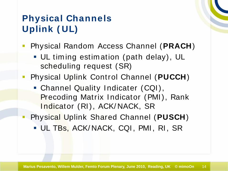
Physical ChannelsUplink (UL)
Physical Random Access Channel (PRACH) UL timing estimation (path delay), UL
scheduling request (SR) Physical Uplink Control Channel (PUCCH) Channel Quality Indicater (CQI),
Precoding Matrix Indicator (PMI), Rank Indicator (RI), ACK/NACK, SR
Physical Uplink Shared Channel (PUSCH) UL TBs, ACK/NACK, CQI, PMI, RI, SR
15Marius Pesavento, Willem Mulder, Femto Forum Plenary, June 2010, Reading, UK © mimoOn
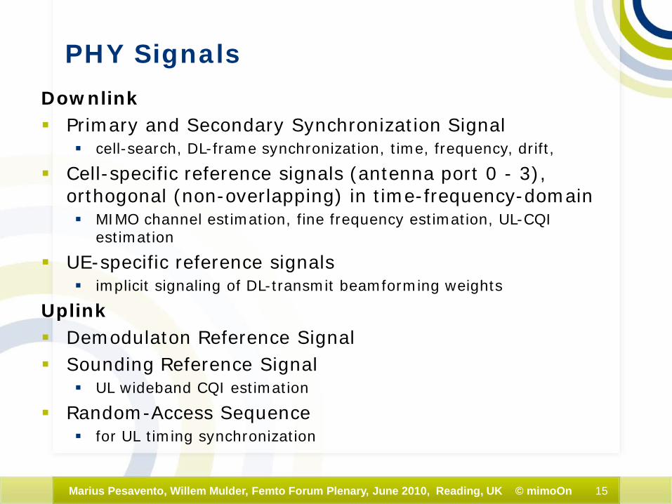
PHY Signals
Downlink Primary and Secondary Synchronization Signal
cell-search, DL-frame synchronization, time, frequency, drift,
Cell-specific reference signals (antenna port 0 - 3), orthogonal (non-overlapping) in time-frequency-domain MIMO channel estimation, fine frequency estimation, UL-CQI
estimation
UE-specific reference signals implicit signaling of DL-transmit beamforming weights
Uplink Demodulaton Reference Signal Sounding Reference Signal
UL wideband CQI estimation
Random-Access Sequence for UL timing synchronization

16Marius Pesavento, Willem Mulder, Femto Forum Plenary, June 2010, Reading, UK © mimoOn
one antenna port(frame structure 1,
normal cyclic prefix)
reference signal 0
two antenna ports(frame structure 1,
normal cyclic prefix)
reference signal 0
reference signal 1
not used for transmissionon this antenna port
slot slot slot
Cell-Specific Reference Signals
carrier frequency: 2.6GHzLTE requirement
max speed: 350km/hmax Doppler frequency: 843Hz
Clarke's modelcoherence time: T > 9/(16π fm)
approx. 3 OFDM symbols
pilot spacing in frequencycoherence bandwidth B ≥ 6x15KHz
B ¼ 1 / (2 π τ) ⇒delay spead τ :
τ ¼ 1 / (2 π B) =1.77µsec (¼ 54 smpls; corresp. to 531 meter )
Port 0 Port 1
Port 0Tx
Tx

17Marius Pesavento, Willem Mulder, Femto Forum Plenary, June 2010, Reading, UK © mimoOn
reference signal 0
reference signal 1
not used for transmissionon this antenna port
reference signal 2
reference signal 3
four antenna ports(frame structure 1,
normal cyclic prefix)
slot slot even slot odd slot even slot odd slot
Cell-Specific Reference Signals
Port 3
Port 2
Port 1
Port 0Tx

18Marius Pesavento, Willem Mulder, Femto Forum Plenary, June 2010, Reading, UK © mimoOn
DL time-frequency structure
•DL payload on DL Shared Channel•Primary synchronization signal •Secondary synchronization signal•Broadcast Channel•DL Control Channel•Reference signal
20MHz 30.72MHz
guard band

19Marius Pesavento, Willem Mulder, Femto Forum Plenary, June 2010, Reading, UK © mimoOn
UL time-frequency structure
demodulation reference
signal (DRS)
soundingreference
signal (SRS)
PUSCH
PUCCH
time / OFDM symbol number
frequ
ency

20Marius Pesavento, Willem Mulder, Femto Forum Plenary, June 2010, Reading, UK © mimoOn
MAC PDU
CB
Seg
-m
enta
tion
Mod
ulat
ion
Layer Mapping
MIMO Precoding
P/S Sync Signals
RefSignal
Frame Builder
IFFT CP Adding
Pulse Shape
Cha
nnel
Cod
ing
Turb
o
HARQ Support& Rate Matching
•HARQ hard buffer for S1, P1, P2
• Subblock interleaver•Rate Matcher, RVs Sc
ram
blin
g
to DACs
TB C
RC
CB
CR
C
CB
C
onca
tena
tion
PDSCH Tx
num
bero
fan
tenn
as
number ofTransport Blocks (TBs)
number ofstreams

21Marius Pesavento, Willem Mulder, Femto Forum Plenary, June 2010, Reading, UK © mimoOn
MAC PDU
frame/RBdemapper
RotatorFreq. Off.
CP Removal FFT
Channel Estimation
Measure-ments
MIMO Detector
FromADCs
Layer Demapper
P/S-Sync Processing
CB
Con
cate
-na
tion
Soft
Dem
odul
ator
8
bit
Turb
oD
ecod
er
HARQ Support & Rate Matching:
•HARQ soft buffer for S1, P1, P2,
•Subblock interleaver•Soft-Combiner 8 bit, RVs D
escr
ambl
ing
TB C
RC
CB
CR
C
CB
sem
enta
tion:
tran
sitio
n fr
om
OFD
M w
ise
to
CB
-wis
e pr
oces
sing
antenna ports
Down-sampling
filter
Fine Frequency estimation
RotatorSamp.D. other CWs
smple drift
PDSCH Rx

22Marius Pesavento, Willem Mulder, Femto Forum Plenary, June 2010, Reading, UK © mimoOn
Transform Precoding
Mixed-Radix DFT
Demod. Ref.
Signal
RBResource Mapper
IFFT CPAdding
Pulse Shape DAC
RotatorFreq. Cor.
MAC PDU
CB
Seg
-m
enta
tion
Mod
ulat
ion
Cha
nnel
Turb
o C
odin
g
Dat
a &
Con
trol
M
ux
Scra
mbl
ing
TB C
RC
CB
CR
C
CB
C
onca
tena
tionHARQ Support
& Rate Matching•HARQ hard buffer for S1,
P1, P2• Subblock interleaver
•Rate Matcher, RVs
RotatorSamp.
Drift
Sound. Ref.
Signal
controlTS36.212Figure
5.2.2-1
Cha
nnel
Inte
rleav
ing
ACK RI
Length 32 block code
CQI and/or PMI reportCQI <= 11 bit
CQI and/or PMI report
CQI > 11 bit
32bit
Cha
nnel
Con
v.
Cod
ing
CB
CR
CRate Matching
PUSCH Tx
number of Transport Blocks (TBs) of different users
to reduce PAPR

23Marius Pesavento, Willem Mulder, Femto Forum Plenary, June 2010, Reading, UK © mimoOn
controlTS36.212Figure
5.2.2-1
MAC PDU
CB
Con
cate
-na
tion
Soft
dem
odul
ator
8.bi
t
Turb
oD
ecod
er
Des
cram
blin
g
TB C
RC
CB
CR
C
CB
Seg
men
tatio
n:Tr
ansi
tion
from
O
FDM
-to
CB
-wis
e pr
oces
sing
Tranform (De)Precoding(mixed-Radix
DFT)
frame/RB Demapper
CP Removal FFT
Demod. Ref.Channel Estimation
Measure-ments
Multi-AntennaReceiver
Sounding Ref.Processing
Dat
a &
Con
trol
D
emux
Frame timing
HARQ Support & Rate Matching:
•HARQ soft buffer for S1, P1, P2,
•Subblock interleaver•Soft-Combiner 8 bit, RVs
FromADCs
Cha
nnel
de
inte
rleav
er
ACK RIBlock decoder(32,11)
Rate DeMatching:•Subblock interleaver
•Soft-Combiner 8 bit, RVsViterbiCB CRC
PUSCH Rx

24Marius Pesavento, Willem Mulder, Femto Forum Plenary, June 2010, Reading, UK © mimoOn
Downlink Control Indicator Format (DCI format)
DCI format 0 is used for the transmission of UL-SCH assignments DCI format 1 is used for the transmission of DL-SCH assignments
for single antenna operation DCI format 1A is used for a compact transmission of DL-SCH
assignments for single antenna operation DCI format 1B is used to support closed-loop single-rank
transmission with possibly contiguous resource allocation DCI format 1C is for downlink transmission of paging, RACH
response and dynamic BCCH scheduling DCI format 2 is used for the transmission of DL-SCH assignments
for MIMO operation DCI format 3 is used for the transmission of TPC commands for
PUCCH and PUSCH with 2-bit power adjustments DCI format 3A is used for the transmission of TPC commands for
PUCCH and PUSCH with single bit power adjustments

25Marius Pesavento, Willem Mulder, Femto Forum Plenary, June 2010, Reading, UK © mimoOn
CRC scramblingwith RNTI /(UE Tx port)
specific
CRCgeneration
L=16
DCI tail bit convolutional
encoder, rate 1/3
interleaver,rate-matching
PDCCHmultiplexing <NIL>element
insertion
cell-specificscrambling
other DCIs
QPSKmodulation
sub-block interleaver(on quadruples of modulated symbols), remove <NULL>
elements
Resource Mapper,(mapping to RE groups)
time first – then frequency
layer mapping,pre-coding:
single antenna port or transmit
diversity
antenna ports 0,...,3
other DL channels
IFFT andCP attachment
MIMOchannel
FFT andCP removal,
frequency and timing correction
Resource demapper(1-3 OFDM symbols,
according to CFI)
sub-block de-inter-leaver
equalizer, MIMO detector,
(requires channel estimation)
soft-demodulator
rate-dematching,
deinterleaving
Viterbi decoder
cell specific de-
scrambling
44 blind decoding attempts (common-
and UE-specific-search-space),
44 PDCCHcandidates
code bit extractionCRC calculation
XOR
CRC extraction
RNTIskip some decodes if RNTI is found
PDCCH processing chain
RNTI: radio network temporary identifier
DCI
User specific search space
(aggregation level)1-CCE (2x6attempts)2-CCE (2x6attempts)4-CCE (2x2attempts),8-CCE (2x2attempts)
Cell specific search space
(aggregation level)4-CCE (2x4attempts)8-CCE (2x2attempts)
26Marius Pesavento, Willem Mulder, Femto Forum Plenary, June 2010, Reading, UK © mimoOn
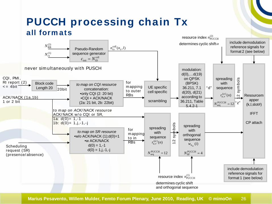
spreading with
sequence
Schedulingrequest (SR)(presence/absence)
Block codeLength 20
never simultaneously with PUSCH
CQI, PMI,RI report (2)<= 4bit
ACK/NACK (1a,1b)1 or 2 bit
to map on CQI resourceconcatenation:
•only CQI (2: 20 bit)•CQI + ACK/NACK
(2a: 21 bit, 2b: 22bit)
to map on SR resource•w/o ACK/NACK (1);d(0)=1
•w ACK/NACKd(0) = 1,-1d(0) = 1,j,-1,-j
to map on ACK/NACK resourceACK/NACK w/o CQI or SR, 1a: d(0)= 1,-11b: d(0)= 1,j,-1,-j
20bit
formapping to outerRBs
formapping to inRBs
Pseudo-Randomsequence generator
cellIDinit Nc =
(2)RBN
(1)csN
),(cellcs lnn s
)()(, nr vuα
12PUCCHseq =N
spreading with
orthogonalsequence
12 s
ymbol
s
)(oc
iwn
4PUCCHSF =N
UE specificcell specific
scrambling
spreading with
sequence
)()(, nr vuα
12PUCCHseq =N
modulation:d(0),…d(19)
on QPSK (BPSK)
36.211, 7.1d(20), d(21)according to
36.211, Table 5.4.2-1
resource index (2)PUCCHn
determines cyclic shift α
Resourcemapper
(k,l,slot#)
IFFT
CP attach
include demodulationreference signals for format 1 (see below)
(1)PUCCHnresource index
determines cyclic shiftand orthogonal sequence
12 s
ymbol
s
include demodulationreference signals for format 2 (see below)
“d”
“z”
PUCCH processing chain Txall formats

27Marius Pesavento, Willem Mulder, Femto Forum Plenary, June 2010, Reading, UK © mimoOn
Resource de-mapper(k,l,slot#)
form
at 2
,2a,
2b
(CQ
I,PM
I,RI)
CP removal
FFT (2048)
format 1,1a,1bACK/NCK w or w/o SR(see next page)
multiplication with
conjugate of
)()(, nr vuα
12PUCCHseq =N
resource index (2)PUCCHn
determines cyclic shift α
IDFT
leng
th 1
2 separateusers
accordingto cyclic shift in time-
domain
multiplication with
conjugate of
)()(, nr vuα
12PUCCHseq =N
resource index (2)PUCCHn
determines cyclic shift α
IDFT
leng
th 1
2 channel estimation
separate users accordingto cyclic shift in time-
domain
tap M(<12) channelcoefficient vector
M depends on numberof shifts in use
matched filtering
withtap Mcoef.
vector
user m
user m
hard
dem
odul
ator
UE specificcell specific
descrambling
segmentation
SR•w/o ACK/NACK (1);d(0)=1
•w ACK/NACKd(0) = 1,-1
d(0) = 1,j,-1,-j
ACK/NACK(1a,1b)
Block decoding(bit-level matched
filter)
CQI, PMI,RI report (2)
QPSK
PUCCH processing Rxformat 2, 2a, 2b

28Marius Pesavento, Willem Mulder, Femto Forum Plenary, June 2010, Reading, UK © mimoOn
Resource de-mapper(k,l,slot#)
on SRresource
form
at 1
,1a,
1b
(SR a
nd A
CK/N
ACK)
CP removal
FFT (2048)
format 2,2a,2b(CQI,PMI,RI)
multiplication with
conjugate of
)()(, nr vuα
12PUCCHseq =N
resource index (2)PUCCHn
determines cyclic shift α
IDFT
leng
th 1
2 separateusers
accordingto cyclic shift in time-
domain
multiplication with
conjugate of
)()(, nr vuα
12PUCCHseq =N
resource index (2)PUCCHn
determines cyclic shift α
IDFT
leng
th 1
2channel
estimation 1
separate users according to cyclic shift in time-domain
tap M(<12) channel
coefficient vector
M depends onnumber of
shifts in use
matched filtering
withtap Mcoef.
vector
user m
user m
hard
dem
odul
ator
UE specificcell specific
descrambling
ACK/NACK
chan
nel e
stim
atio
n2se
para
te u
sers
acc
ordi
ng to
orth
ogon
al
cove
r seq
uenc
e (d
espr
eadi
ng)
desp
read
ing
sepa
rate
use
re a
ccor
ding
to
orth
ogon
al s
eque
nce
SR
PUCCH processing Rxformat 1

29Marius Pesavento, Willem Mulder, Femto Forum Plenary, June 2010, Reading, UK © mimoOn
Resource de-mapper(k,l,slot#)
on ACK/NACK
resource
form
at 1
,1a,
1b
(SR a
nd A
CK/N
ACK)
CP removal
FFT (2048)
format 2,2a,2b(CQI,PMI,RI)
multiplication with
conjugate of
)()(, nr vuα
12PUCCHseq =N
resource index (2)PUCCHn
determines cyclic shift α
IDFT
leng
th 1
2 separateusers
accordingto cyclic shift in time-
domain
multiplication with
conjugate of
)()(, nr vuα
12PUCCHseq =N
resource index (2)PUCCHn
determines cyclic shift α
IDFT
leng
th 1
2channel
estimation 1
separate users according to cyclic shift in time-domain
tap M(<12) channel
coefficient vector
M depends onnumber of
shifts in use
matched filtering
withtap Mcoef.
vector
user m
user m
hard
dem
odul
ator
UE specificcell specific
descrambling
ACK/NACK
chan
nel e
stim
atio
n2se
para
te u
sers
acc
ordi
ng to
orth
ogon
al
cove
r seq
uenc
e (d
espr
eadi
ng)
desp
read
ing
sepa
rate
use
re a
ccor
ding
to
orth
ogon
al s
eque
nce
PUCCH processing Rxformat 1a, 1b

30Marius Pesavento, Willem Mulder, Femto Forum Plenary, June 2010, Reading, UK © mimoOn
spreading with
sequence
formapping to outerRBs
formapping to inRBs
Pseudo-Randomsequence generator
cellIDinit Nc =
(2)RBN
(1)csN
),(cellcs lnn s
)()(, nr vuα
12PUCCHseq =N
spreading with
orthogonalsequence
12 s
ymbol
s
)(oc
iwn
4PUCCHSF =N
UE specificcell specific
scrambling
spreading with
sequence
)()(, nr vuα
12PUCCHseq =N
modulation:d(0),…d(19)
on QPSK36.211, 7.1d(20), d(21)according to
36.211, Table 5.4.2-1
resource index (2)PUCCHn
determines cyclic shift α
Resourcemapper
(k,l,slot#)
IFFT
CP attach
(1)PUCCHnresource index
determines cyclic shiftand orthogonal sequence
12 s
ymbol
s
input sequence for format 1
input sequence for format 2
Demodulation reference signals for PUCCH format 2

31Marius Pesavento, Willem Mulder, Femto Forum Plenary, June 2010, Reading, UK © mimoOn
3 xrepetition
ACK/NACK1 bit
BPSK(I or Q)
symbol levelSpreading,
length 4 orthogonal sequence
3bit
super-positionof different
ACK/NACKS
3 symbols 12 symbols
resource mapper,PHICH group is
mapped to 3 groups of 4 REs
scrambling
12 s
ymbol
s
layer mapperSISO or MIMO TD
FFT / CP insertion
MIMOchannel
CP removal/IFFT
resource demapperMIMO detectordescrambling
matched filterlength(12)
ACK/NACK1 bit
other ACK/NACK1 bit
other ACK/NACK1 bit
Location depends on the index of the first RB of the corresponding PUSCH transmission
PHICH(DL HARQ)
Max. 8 different sequences
Selection depends on the index of the first RB of the corresponding PUSCH transmission

32Marius Pesavento, Willem Mulder, Femto Forum Plenary, June 2010, Reading, UK © mimoOn
MIB
cell specificscrambling scrambling
tail bit convolutional
encoder, rate 1/3
QPSK modulation
layer mapping forsingle antenna or transmit diversity
precodingSFD
resourcemapping
IFFTCP inclusion
MIMOchannel
CP removelFFT
Equalization(SISO, MISO, or TD)
soft demodulator
(QPSK)
channel estimates
Viterbi decoder
interleaver,rate-matching
rate matching buffer
CRC attachCRC mask
code bit extraction, CRC
computationantenna config
CRC extaction
XOR
antenna config
frame no 0,1,2,3
PBCH
PBCH carries important PHY information:system bandwidth, number of transmit antennas, PHICH configuration and system frame number,…
maskedCRC
mask
MIB
After successful reception of PBCH, UE can read D-BCH in
PDSCH (including PCFICH and PDCCH) which carries system
information not including in PBCH

33Marius Pesavento, Willem Mulder, Femto Forum Plenary, June 2010, Reading, UK © mimoOn
possible cell specificroot-sequences,(conjugate)
RACH sequence extends over several slots
CP inclusion(3168, 21024,
6240)
add to OFDM frame in time
domain
UL Tx signal in time domain:PUSCH, PUCCH,DRS,SRS,including CP
Channelphase rotation,
(mixing,frequency shift to DC)
decimation1/24
LP filter1/24DFT 1024Multiplication
IDFT 1024(results in change of
sampling rate)
Peak dection,path delay estimation
RACH sequence, associated timing-advance
RACH sequence, associated timing-advance
Zadoff-Chu sequence (L=839), selectec from set of 64 sequences),different root-sequences or different cyclic shifts, Create in 839 sequence in frequency domain
Zero padding to 1024
IDFT of length 1024
Upsampling by 24,
LP filtering
Rotator, frequency
shift
PRACH
correlation (convolution) in time domainreplaced by multiplication in frequency domain

34Marius Pesavento, Willem Mulder, Femto Forum Plenary, June 2010, Reading, UK © mimoOn
PCFICHDL Control Format
block codeL=16
2 bits scamblingcell and
subframe dependent
modulatorQPSK
layer mapping
FFT / CP insertion
power boosting
power control
MIMOchannel
resourcemapper
(4 blocks of 4REs = 1RE
group)
cell ID
precodingSISO or
Tx diversity
CP removalII
FFT
resource demap
MIMO detectiondemodulatordescramblingblock
detection
number ofOFDM symbolsreserve for control1,2,3

35Marius Pesavento, Willem Mulder, Femto Forum Plenary, June 2010, Reading, UK © mimoOn
Rate matching and HARQ processing
systematicparity 1parity 2
sub-blockinterleaver
column permutation
write-in row-wise
read-out column-wise S1
P1P2
MUX
S1
P1/P2
RV0
RV2
RV3
RV1

36Marius Pesavento, Willem Mulder, Femto Forum Plenary, June 2010, Reading, UK © mimoOn
HARQ timing

37Marius Pesavento, Willem Mulder, Femto Forum Plenary, June 2010, Reading, UK © mimoOn
UE Categories synchronous HARQ in UL, ACK/NACK in 4 TTI after UL reception,
re-transmission (UL) in 8 TTI after initial transmission, total of 8 HARQ processes asynchronous HARQ in DL, ACK/NACK in 4 TTI after DL reception, retransmission
with DL scheduling grant, total number of 8 HARQ processes
Downlink physical layer parameter values set by UE Category
UE CategoryMaximum number of DL-SCH transport block bits received
within a TTI
Maximum number of bits of a DL-SCH transport
block received within a TTI
Total number of soft
channel bits
Maximum number of supported layers for
spatial multiplexing in DL
Category 1 10296 10296 250368 1
Category 2 51024 51024 1237248 2
Category 3 102048 75376 1237248 2
Category 4 150752 75376 1827072 2
Category 5 302752 151376 3667200 4
Uplink physical layer parameter values set by UE Category
UE Category
Maximum number of bits of an UL-SCH transport block transmitted within a TTI
Support for 64QAM in UL
Category 1 5160 No
Category 2 25456 No
Category 3 51024 No
Category 4 51024 No
Category 5 75376 Yes
≈ 8HARQ bufferx(3(S1,P1,P2)x10296+
12(termination))

38Marius Pesavento, Willem Mulder, Femto Forum Plenary, June 2010, Reading, UK © mimoOn
UE Categories

39Marius Pesavento, Willem Mulder, Femto Forum Plenary, June 2010, Reading, UK © mimoOn
TDD: DL grants and ACK/NACK reporting
FDD: only one DL (and one UL) grant per TTI. Corresponding DL TBs need to be ACK/NACK 4 TTIs after reception (1 or 2 bits).
TDD: ACK/NACK required for detected PDSCH and for DL SPS release on PDCCH.
TDD: usually one DL grant (but up to 2 DL grants, in special case of UL-DL config. 0) can be received within one TTI.

40Marius Pesavento, Willem Mulder, Femto Forum Plenary, June 2010, Reading, UK © mimoOn
subframe 1 ms
one radio frame, Tf = 307200*TS = 10 ms
TDD ACK/NACKRecall: Frame Structure Type 2: TDD
DL#0
S#1
UL#2
UL/DL#3
UL/DL#4
S/DL#6
DL#5
UL/DL#7
UL/DL#8
UL/DL#9
Downlinksubframe
Uplinksubframe
Special guardsubframe for
DL to UL switch
Special guardsubframe orDownlink SF
Uplink orDownlinksubframe
special subframe: DL to UL switching
S#1 or #6
DwPTSGP UpPTS
DwPTS: DL pilot time slotshortend DL subframe
(3,8,9,10,11, or 12 OFDM symbols) reference signals, primary sync and control, PDSCH
GP: Guard period(1,2,3,4,7,8,9,10 OFDM symbols)
UpPTS: UL pilot time slot(1 or 2 OFDM symbols)
sounding reference or RACH
SS
SR
S a
ndC
ontro
lP
SS
0 1 2

41Marius Pesavento, Willem Mulder, Femto Forum Plenary, June 2010, Reading, UK © mimoOn
TDD: UE ACK/NACK procedure(PUSCH transmission and PHICH reception)
TDD UL/DLConfiguration
subframe number i
0 1 2 3 4 5 6 7 8 9
0 6,7 4 6,7 4
1 4 6 4 6
2 6 6
3 6 6 6
4 6 6
5 6
6 6 4 7 4 6
•ACK/NACK received on PHICHin subframe i•for UL transmission in subframe i - k,where the values for k are given inthe table.
k for TDD configurartion 0-6
TDD UL/DLConfiguration
subframe number i
0 1 2 3 4 5 6 7 8 9
0 4 7 6 4 7 6
1 4 6 4 6
2 6 6
3 6 6 6
4 6 6
5 6
6 4 6 6 4 7
UE Rx Perspective•for UL transmission in subframe i,•ACK/NACK received on PHICH in subframe i + k, where the values for k are given inthe table.
k for TDD configurartion 0-6
UE Tx Perspective

42Marius Pesavento, Willem Mulder, Femto Forum Plenary, June 2010, Reading, UK © mimoOn
DL control issues in TDD DL HARQ
TDD UL/DLConfig.
DL subframe number n
0 1 2 3 4 5 6 7 8 9
0 4 6 4 6
1 7 6 4 7 6 4
2 7 6 4 8 7 6 4 8
3 4 11 7 6 6 5 5
4 12 11 8 7 7 6 5 4
5 12 11 9 8 7 6 5 4 13
6 7 7 7 7 5
•reception of PDSCH in subframe n•ACK/NACK on PUSCH or PUCCH in subframe n + k
k for TDD configurartion 0-6
TDD UL/DLConfig.
DL subframe number n
0 1 2 3 4 5 6 7 8 9
0 6 4 6 4
1 7,6 4 7,6 4
2 8,7,4,6 8,7,4,6
3 7,6,11 6,5 5,4
4 12,8,7,11 6,5,4,7
5 13,12,9,8,7,5,4,11
6 7 7 5 7 7
•ACK/NACK on PUSCH or PUCCH in subframe n•for reception of PDSCH insubframe n - k
k for TDD configurartion 0-6
UE Rx Perspective UE Tx Perspective
Multiple ACK/NACK in one subframe:Requieres ACK/NACK bundling (logical AND of codewords) or ACK/NACK multiplexing.

43Marius Pesavento, Willem Mulder, Femto Forum Plenary, June 2010, Reading, UK © mimoOn
TDD: Downlink Assignment Index DAIto prevent ACK/NACK errors due to bundling
k‘ for TDD configurartion 0-6 and DAI in DCI format 0 (UL assignments)
•DAI indicates the number of subframes with PDSCH receptions and SPS releases detected within n-k and n (k 2 K) that need to be bundeled in the UL ACK/NACK signaling.•DAI is used only for TDD
TDD UL/DLConfig.
DL subframe number n
0 1 2 3 4 5 6 7 8 9
0 DAI 6 4 DAI 6 4
1 DAI 6 4 DAI DAI 6 4 DAI
2 4 DAI 4 DAI
3 DAI 4 4 4 DAI DAI
4 4 4 DAI DAI
5 4 DAI
6 DAI DAI 7 7 5 DAI DAI 7 7 DAI
TDD UL/DLConfig.
DL subframe number n
0 1 2 3 4 5 6 7 8 9
0 DAI DAI 6 4 DAI DAI 6 4
1 DAI 7,6 4 DAI DAI 7,6 4 DAI
2 8,7,4,6 DAI 8,7,4,6 DAI
3 DAI 7,6,11 6,5 5,4 DAI DAI
4 12,8,7,11 6,5,4,7 DAI DAI
5 13,12,9,8,7,5,4,11 DAI
6 DAI DAI 7 7 5 DAI DAI 7 7 DAI
k for TDD configurartion 0-6 and DAI in DCI formats 1/1A/1B/1D/2/2A (DL)
0 or 4 or 841,1
3 or 731,0
2 or 620,1
1 or 5 or 910,0
Number of subframes with PDSCH transmission
DAIMSB, LSB
ULDAIV DL
DAIVor

44Marius Pesavento, Willem Mulder, Femto Forum Plenary, June 2010, Reading, UK © mimoOn
End of Part 1
Thank you!!!
45Marius Pesavento, Willem Mulder, Femto Forum Plenary, June 2010, Reading, UK © mimoOn
Backup slides

46Marius Pesavento, Willem Mulder, Femto Forum Plenary, June 2010, Reading, UK © mimoOn
3GPP LTE roadmap