lte lbt wi-fi coexistence module documentation - ns-3tomh/ns-3-lbt-documents/lbt-wifi... · lte lbt...
TRANSCRIPT
LTE LBT Wi-Fi Coexistence ModuleDocumentation
Release ns-3-lbt rev. b48bfc33132b
ns-3 project
February 15, 2016

CONTENTS
1 Introduction 1
2 Design 32.1 Use case requirements . . . . . . . . . . . . . . . . . . . . . . . . . . . . . . . . . . . . . . . . . . 32.2 LBT design . . . . . . . . . . . . . . . . . . . . . . . . . . . . . . . . . . . . . . . . . . . . . . . . 32.3 Applications . . . . . . . . . . . . . . . . . . . . . . . . . . . . . . . . . . . . . . . . . . . . . . . 52.4 Scenario design . . . . . . . . . . . . . . . . . . . . . . . . . . . . . . . . . . . . . . . . . . . . . . 92.5 References . . . . . . . . . . . . . . . . . . . . . . . . . . . . . . . . . . . . . . . . . . . . . . . . 10
3 Usage 113.1 Getting the LBT code . . . . . . . . . . . . . . . . . . . . . . . . . . . . . . . . . . . . . . . . . . 113.2 Compiling the LBT code . . . . . . . . . . . . . . . . . . . . . . . . . . . . . . . . . . . . . . . . . 113.3 Global Values . . . . . . . . . . . . . . . . . . . . . . . . . . . . . . . . . . . . . . . . . . . . . . . 123.4 Examples . . . . . . . . . . . . . . . . . . . . . . . . . . . . . . . . . . . . . . . . . . . . . . . . . 12
4 Tests and Validation 15
5 Results 175.1 Scripted Indoor Scenario . . . . . . . . . . . . . . . . . . . . . . . . . . . . . . . . . . . . . . . . . 17
6 Open Issues and Future Work 23
Bibliography 25
i

ii
CHAPTER
ONE
INTRODUCTION
The LAA Wi-Fi Coexistence module provides support to simulate with ns-3 the scenarios for the coexistence betweenunlicensed variants of LTE in the 5 GHz band and Wi-Fi systems, following the description in [TR36889].
This document describes an effort to develop ns-3 LTE models for ‘Listen-Before-Talk’ (LBT) being defined as partof LTE Release 13 by 3GPP. This effort follows on an initial project to extend ns-3 to support basic Wi-Fi and LTEcoexistence studies modeling LTE duty-cycle as the coexistence mechanism.
The code resides in a module named the ‘LAA’ coexistence module, where LAA stands for Licensed-Assisted Access(LAA). We wish to clarify that as of this writing, specifications are being finalized for LAA within 3GPP, and the ns-3LBT models are not completely conformant to the emerging specification, although they aim to correspond as closelyas possible subject to available modeling resources. In addition, other LTE technologies separate from 3GPP LAAhave been proposed, including LTE-Unlicensed (LTE-U). ns-3 does not have an LTE-U model either (i.e. a modelclosely conformant to the specification in the LTE-U Forum), but does have a duty-cycled LTE capability. We haveselected the acronym ‘LTE-DC’ (for LTE duty cycle) to refer to the duty-cycle model, and ‘LAA’ or ‘LBT’ acronymsfor the model of Listen-Before-Talk.
The support for simulating the LTE and Wi-Fi technology is provided by the separate ns-3 LTE and Wi-Fi modules;the LAA Wi-Fi Coexistence module focuses on the additional features that are needed to create a simulation scenariothat incorporates both technologies. The source code for the LAA Wi-Fi Coexistence module lives in the directorysrc/laa-wifi-coexistence.
The LTE and Wi-Fi modules of ns-3, as stand-alone modules, are separately documented in other documents. Thisdocument primarily concerns itself with extensions and tests to support coexistence scenarios. Over time, extensionsfound in this module may migrate to the existing ns-3 main development tree.
The rest of this document is organized into five major chapters:
2. Design: Describes how ns-3 has been extended to support coexistence studies, and describes scenario design.
3. Usage: Documents how users may run and extend these simulation scenarios themselves.
4. Validation: Documents how the models and scenarios have been verified and validated by test programs.
5. Results: Documents preliminary results from some scenarios and how to reproduce them.
6. Open Issues and Future Work: Describes topics for which future work on model or scenario enhancements isrecommended, or for which questions on interpretations of standards documents may be listed.
1
LTE LBT Wi-Fi Coexistence Module Documentation, Release ns-3-lbt rev. b48bfc33132b
2 Chapter 1. Introduction
CHAPTER
TWO
DESIGN
In the following, we document the design decisions and modeling assumptions on which the LBT extensions to theLAA Wi-Fi Coexistence module are based.
ns-3 or any performance modeling tool will be able to satisfy some or all of the desired aspects of the scenariodefinitions. We summarize herein the requirements driving this design, and then go into greater detail about the scopeand limitations of the ns-3-based framework.
2.1 Use case requirements
This module is intended to facilitate coexistence performance evaluations as described in [TR36889]. To summarize,[TR36889] describes indoor and outdoor scenarios that may be parameterized and instrumented to study questions offairness and performance impacts of LAA services with respect to Wi-Fi.
In summary, this module intends to extend ns-3 to support the modeling of deployment scenarios, summarized inSection 6 of [TR36889], involving deployment of multiple system operators (Wi-Fi and LAA) in the same radioregion. Annex A of [TR36889] further outlines desired parameters for scenario configuration, system configuration,and performance metrics.
Rather than restating the requirements herein, we suffice to state that the overall target is to support simulation scenar-ios as outlined in Section 8 of [TR36889] and specification agreements found in [RP-152233].
2.2 LBT design
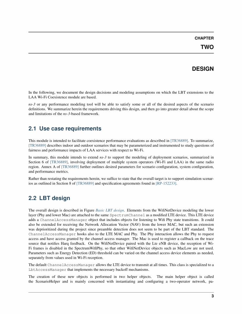
The overall design is described in Figure Basic LBT design. Elements from the WifiNetDevice modeling the lowerlayer (Phy and lower Mac) are attached to the same SpectrumChannel as a modified LTE device. This LTE deviceadds a ChannelAccessManager object that includes objects for listening to Wifi Phy state transitions. It couldalso be extended for receiving the Network Allocation Vector (NAV) from the lower MAC, but such an extensionwas deprioritized during the project since preamble detection does not seem to be part of the LBT standard. TheChannelAccessManager hooks also to the LTE MAC and Phy. The Phy interaction allows the Phy to requestaccess and have access granted by the channel access manager. The Mac is used to register a callback on the tracesource that notifies Harq feedback. On the WifiNetDevice paired with the Lte eNB device, the reception of Wi-Fi frames is disabled in the SpectrumWifiPhy, so that other WifiNetDevice objects such as MacLow are not used.Parameters such as Energy Detection (ED) threshold can be varied on the channel access device elements as needed,separately from values used in Wi-Fi reception.
The default ChannelAccessManager allows the LTE device to transmit at all times. This class is specialized to aLbtAccessManager that implements the necessary backoff mechanisms.
The creation of these new objects is performed in two helper objects. The main helper object is calledthe ScenarioHelper and is mainly concerned with instantiating and configuring a two-operator network, pa-
3
LTE LBT Wi-Fi Coexistence Module Documentation, Release ns-3-lbt rev. b48bfc33132b
Figure 2.1: Basic LBT design
rameterized differently depending on the scenario. An additional helper was introduced in this phase, calledLaaWifiCoexistenceHelper, to configure LBT on a set of LTE eNodeB devices.
2.2.1 LTE design
In LTE module is added a new class ChannelAccessManager. This class is hooked with LteEnbRrc, whichthen configures LteEnbMac and LteEnbPhy to be aware of the ChannelAccessManager.
ChannelAccessManager is a class that defines the channel access mechanism. Since LTE does not need to haveany special channel access mechanism, the default mechanism is that every time the LTE eNodeB requires access tochannel, the access is approved immediately and the eNodeB starts to transmit.
This new ChannelAccessManager is implemented in such a way as to not affect the existing functionality of theLTE module.
The ChannelAccessManager type can be configured by using the methodLteEnbPhy::SetChannelAccessManager of the LteEnbPhy class. ChannelAccessAttributeof the LteEnbRrc module. Each LTE eNodeB device has its own instance of LteEnbRrc, thus addingChannelAccessManager as an attribute of LteEnbRrc class allows that each eNodeB device has itsown ChannelAccessManager instance. To configure the type of ChannelAccessManager through ns-3configuration system, there is a new global value called ChannelAccessManager that takes the followingpossible values: Default, DutyCycle, and Lbt.
2.2.2 DutyCycleAccessManager
The duty cycle access manager is an alternative implementation of the LTE duty cycling capability implemented inphase 1, but this time it is implemented as a subclass of the parent ChannelAccessManager class. It was not usedvery much in this phase but was written as a precursor to the LbtAccessManager. There are no current examples ortests that use this class.
It can be configured via the following attributes:
• OnDuration (describe)
• OnStartTime (describe)
• DutyCyclePeriod (describe)
4 Chapter 2. Design

LTE LBT Wi-Fi Coexistence Module Documentation, Release ns-3-lbt rev. b48bfc33132b
2.2.3 LbtAccessManager
In src/laa-wifi-coexistence/model directory, we created another class called LbtAccessManager thatinherits from ChannelAccessManager. This class performs listen-before-talk and exponential backoff accordingto current 3GPP RAN 1 designs [RP-152233].
To configure LbtAccessManager we need to provide it to the WifiPhy and MacLow to which it will connect itslisteners:
Ptr<LbtAccessManager> lbtAccessManager = Create<LbtAccessManager>();lbtAccessManager->SetupPhyListener(wifiPhy);rrc->SetChannelAccessManager(lbtAccessManager);
The setup of this is currently done by LaaWifiCoexistenceHelper, so the user does not need to know how tosetup this, just to call the function of LaaWifiCoexistenceHelper:
LaaWifiCoexistenceHelper laaWifiCoexistenceHelper;laaWifiCoexistenceHelper.ConfigureEnbDevicesForLbt(bsDevices, phyParams);
Previous code is currently encapsulated into new function ConfigureLaa of ScenarioHelper which takes careof configuration of LBT LTE node. So the user can just call ConfigureLaa function from ScenarioHelperclass.
LbtAccessManager is also implementing two listeners, one from WifiPhy and other for MacLow. This first im-plementation is very similar to wifi DcfManager implementation.
2.3 Applications
Applications are added to the scenario according to guidelines in [TR36889]. There are three main classes of traffic:
• small file transfers
• voice flows
• constant bit rate streams
TR36.889 mainly discusses small file transfers and voice flows, and refers also to TR36.814 ([TR36814]).
Applications are controlled by passing command-line arguments to the laa-wifi-indoor andlaa-wifi-simple programs. The argument --transport=<mode> will select either FTP over UDP(Ftp), FTP over TCP (Tcp), or constant bit rate UDP (Udp). e.g.
./waf --run "laa-wifi-indoor --transport=Ftp ..."
./waf --run "laa-wifi-indoor --transport=Tcp ..."
./waf --run "laa-wifi-indoor --transport=Udp ..."
The voice application can be added on top of these flows, as described below. That is, one of Ftp, Tcp, or Udp shouldbe specified, and then on top of the one selected, additional voice flows can be added.
2.3.1 FTP over UDP application
Annex A of TR36.889 specifies traffic models for both indoor and outdoor scenarios. Two models, FTP Model 3 andFTP Model 1, are suggested, with FTP Model 1 being defined in TR36.814, and FTP Model 3 being described asa variant of the FTP Model 2 defined in TR36.814. We implemented FTP Model 1 support and not FTP Model 3support.
The specification of FTP Model 3 in TR36.889 was not completely clear to the authors:
2.3. Applications 5

LTE LBT Wi-Fi Coexistence Module Documentation, Release ns-3-lbt rev. b48bfc33132b
FTP Model 3: Based on FTP model 2 as in TR 36.814 with the exception thatpackets for the same UE arrive according to a Poisson process with arrival rate 𝜆and the transmission time of a packet is counted from the time instance it arrivesin the queue.
since lambda was unspecified (its relationship to the user arrival rate lambda was not clear), and it was also not clearhow a Poisson arrival process for packet arrivals corresponded to a file transfer.
FTP Model 1 is described in section A.2.1.3.1 of TR36.814. In an operator network, files arrive for transfer accordingto a Poisson process with a lambda value that, for file transfers of 0.5 Mbytes, ranges from [0.5, 1, 1.5, 2, 2.5]. Aslambda increases, the traffic intensity increases; on average, every 1/lambda seconds, a new file arrival occurs. In eachoperator network, a separate file generation process governed by lambda is implemented, and all files are originatedfrom a node in the backhaul network towards one of the UEs. So, for instance, if lambda equals 1, each second (onaverage) a UE will be picked at random in each operator network and a file transfer will be started towards it from thebackhaul network node.
In this simulation framework, we make use of the IP flow monitor tool to track throughput and latency of applicationtraffic, and the file transfer application is implemented in a new class ns3::FileTransferApplication. Inother 3GPP simulations, the upper protocol layers above Wi-Fi or LTE are not implemented, so FTP Model 1 does notrefer to the TCP-supported Internet File Transfer Protocol (FTP) but to a raw file transfer.
In our simulations, the use of the transport mode Ftp will cause files to be sent over UDP/IP, and throughput andlatency to be measured at the IP layer.
The argument --ftpLambda=<lambda> will allow a different value of lambda to be passed, thereby varying thetraffic intensity.
./waf --run "laa-wifi-indoor --transport=Ftp --ftpLambda=0.5 ..."
The relevant parts of TR36.889 for performance evaluation of these flows can be found in Annex A:
Performance metric• User perceived throughput (UPT)
- UPT CDF• File throughput is calculated per file• Unfinished files should be incorporated in the UPT calculation.
• The number of served bits (possibly zero) of an unfinished file bythe end of the simulation is divided by the served time (simulationend time - file arrival time).
• User throughput is the average of all its file throughputs• Latency (From packet arrival in devices (eNB, AP, UE, STA) MAC buffer to
successful transmission (including retransmission) of packet)- Latency CDF
• Average buffer occupancy (BO)- Details in appendix A 2.3
• Ratio of mean served cell throughput and offered cell throughputindependently for DL and for UL denoted by 𝜌
We do not support all of these statistics, but instead provide the following statistics. User perceived throughput ismeasured by our IP-based Flow Monitor tool which tags packets as they traverse the network, records their history,and can be used to output summary statistics on a flow-by-flow basis. Since the IP layer is the user of the LTE andWi-Fi layers, this tool can provide a measure of the UPT. We do not explicitly measure unfinished files; rather, weallow the simulation to linger for a few more seconds after application sending processes end, to allow file transfers tofinish. The latency is also measured by the flow monitor tool, although we measure the user perceived latency (fromarrival in devices to successful delivery of packet), and provide a means to generate a CDF. We do not measure averagebuffer occupancy (ABO), and since we do not presently incorporate uplink traffic, we do not measure the ratio of meanserved cell throughput.
6 Chapter 2. Design
LTE LBT Wi-Fi Coexistence Module Documentation, Release ns-3-lbt rev. b48bfc33132b
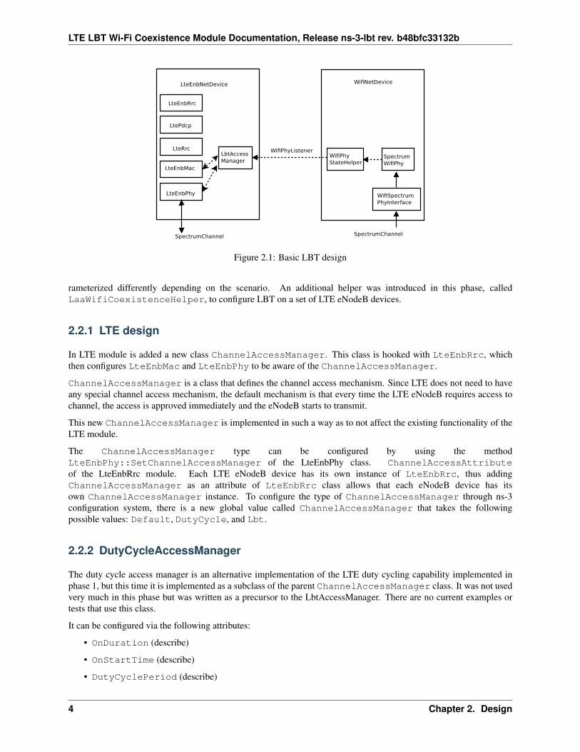
The scenarios will cause some text files to be generated and some output of the flow monitor to be displayed onstandard output. Below is an example of the output printed to standard output.
--------monitorB----------Flow 2 (12.0.0.1:49153 -> 18.0.0.6:16384) proto UDP
Tx Packets: 4799Tx Bytes: 287940TxOffered: 0.04799 MbpsRx Bytes: 287940Throughput: 0.0480096 MbpsMean delay: 0.618888 msMean jitter: 0.471148 msRx Packets: 4799
Each UDP flow will have a record such as this. The measuring points are at the IP protocol layer (i.e. just above Wi-Fior LTE devices) at the entry point and exit point of the application flow.
The TxOffered and Throughput are different quantities, and are calculated differently. We rely on theThroughput statistic, which we define as the number of received bits divided by the flow “receive duration.” Thisduration is defined as the time difference between the last and first packet reception of the flow. The TxOfferedquantity uses a different definition of duration; namely, the duration time of the overall FTP file generation process. Itis only meaningful for flows that persist for the full duration of the application “on time” of the simulation.
Similarly, each simulation run will generate two files recording the summary statistics from all flows, such as (e.g.):
laa_wifi_indoor_eD_-62.0_ftpLambda_2.5_cellA_Wifi_operatorAlaa_wifi_indoor_eD_-62.0_ftpLambda_2.5_cellA_Wifi_operatorB
Sample file contents may look like this:
2 12.0.0.1:49153 18.0.0.6:16384 4799 287940 0.047990 287940 0.048010 0.618888 0.471148 47993 12.0.0.1:49154 18.0.0.5:50000 354 521912 0.086985 521912 90.324991 20.781531 0.130188 3544 12.0.0.1:49155 18.0.0.6:50000 354 521912 0.086985 521912 110.158512 18.914825 0.106678 354
Each line corresponds to a single flow, and readers will note the first line for flow number 2 has statistics that matchthe excerpt from standard output printed above.
The latency (column 8) and throughput (column 9) values of this file can be extracted to generate CDFs and plotsthereof.
2.3.2 FTP over TCP application
The ns-3 framework supports the substitution of the TCP transport protocol in place of UDP. This can be specified bypassing the Tcp option to the transport argument; e.g.:
./waf --run "laa-wifi-indoor --transport=Tcp --ftpLambda=0.5 ..."
In this case, the packets will flow over a TCP connection, but otherwise, the application behaves and is configured thesame as the FTP over UDP configuration.
2.3.3 Constant bit rate streams
Constant bit rate streams can be supported using the built-in ns-3 UdpClient and UdpServer applications. UnlikeFTP-based applications that transfer files in a bursty manner towards one UE at a time, the constant bit rate streamsare enabled for all UEs in both operator networks, at the uniform data rate specified.
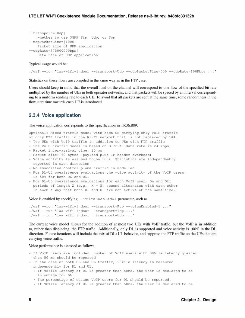
There are two global values exposed as arguments that can configure the Udp transport:
2.3. Applications 7
LTE LBT Wi-Fi Coexistence Module Documentation, Release ns-3-lbt rev. b48bfc33132b
--transport=[Udp]whether to use 3GPP Ftp, Udp, or Tcp
--udpPacketSize=[1000]Packet size of UDP application
--udpRate=[75000000bps]Data rate of UDP application
Typical usage would be:
./waf --run "laa-wifi-indoor --transport=Udp --udpPacketSize=500 --udpRate=100Kbps ..."
Statistics on these flows are compiled in the same way as in the FTP case.
Users should keep in mind that the overall load on the channel will correspond to one flow of the specified bit ratemultiplied by the number of UEs in both operator networks, and that packets will be spaced by an interval correspond-ing to a uniform sending rate to each UE. To avoid that all packets are sent at the same time, some randomness in theflow start time towards each UE is introduced.
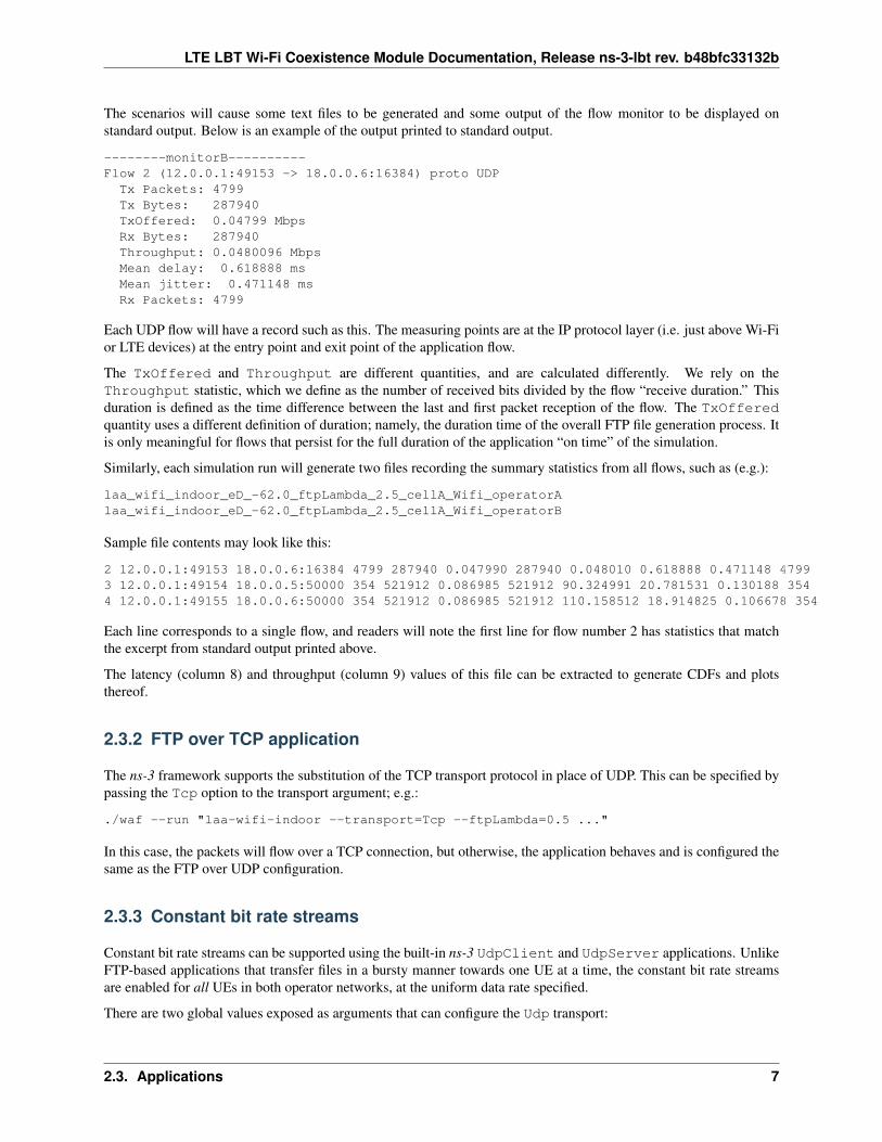
2.3.4 Voice application
The voice application corresponds to this specification in TR36.889:
Optional: Mixed traffic model with each UE carrying only VoIP trafficor only FTP traffic in the Wi-Fi network that is not replaced by LAA.• Two UEs with VoIP traffic in addition to UEs with FTP traffic• The VoIP traffic model is based on G.729A (data rate is 24 kbps)• Packet inter-arrival time: 20 ms• Packet size: 60 bytes (payload plus IP header overhead)• Voice activity is assumed to be 100%. Statistics are independently
reported in each direction• No associated control plane traffic is modelled• For DL+UL coexistence evaluations the voice activity of the VoIP users
is 50% for both DL and UL.• For DL+UL coexistence evaluations for each VoIP user, On and Off
periods of length X (e.g., X = 5) second alternates with each otherin such a way that both DL and UL are not active at the same time.
Voice is enabled by specifying --voiceEnabled=1 parameter, such as:
./waf --run "laa-wifi-indoor --transport=Ftp --voiceEnabled=1 ..."
./waf --run "laa-wifi-indoor --transport=Tcp ..."
./waf --run "laa-wifi-indoor --transport=Udp ..."
The current voice model allows for the addition of at most two UEs with VoIP traffic, but the VoIP is in additionto, rather than displacing, the FTP traffic. Additionally, only DL is supported and voice activity is 100% in the DLdirection. Future iterations will include the mix of DL+UL behavior, and suppress the FTP traffic on the UEs that arecarrying voice traffic.
Voice performance is assessed as follows:
• If VoIP users are included, number of VoIP users with 98%ile latency greaterthan 50 ms should be reported
• In the case of both DL and UL traffic, 98%ile latency is measuredindependently for DL and UL.• If 98%ile latency of DL is greater than 50ms, the user is declared to bein outage for DL.
• The percentage of outage VoIP users for DL should be reported.• If 98%ile latency of UL is greater than 50ms, the user is declared to be
8 Chapter 2. Design
LTE LBT Wi-Fi Coexistence Module Documentation, Release ns-3-lbt rev. b48bfc33132b
in outage for UL.• The percentage of outage VoIP users for UL should be reported.
• If max(98%ile latency of DL, 98%ile latency of UL) is greater than50ms, the user is declared to be in outage.
• The percentage of outage VoIP users should be reported
A new ns-3 VoiceApplication was designed with the above in mind. The application exports trace sources for everypacket sent and received. Each packet contains a monotonically increasing sequence number and a timestamp, andpadding bytes are added to make the packet conform to the requested packet size. The latency of each packet can betracked by comparing the arrival time at the server with the timestamp that was placed in the packet by the client.
The following attributes are configurable on the VoiceApplication:
• PacketSize: The number of payload bytes per packet. Includes any bytes above UDP header or above link layerheader if packet socket used. Minimum of 12 bytes.
• Interval: Time interval between packets.
• SendEnabled: Whether application sending is disabled (in which case it just receives packets).
• Local: The local address to bind to
• Remote: The peer address to connect to
• Protocol: The TypeId of the socket factory to use (e.g. Udp or PacketSocket).
• LatencyThreshold: Accept the packet if latency is not greater than this threshold
• TypeOfService: For IP transport, set the value of IP TOS byte.
The IP TOS is set by default to Expedited Forwarding, and such packets will be enqueued in the AC_VO accesscategory in Wi-Fi.
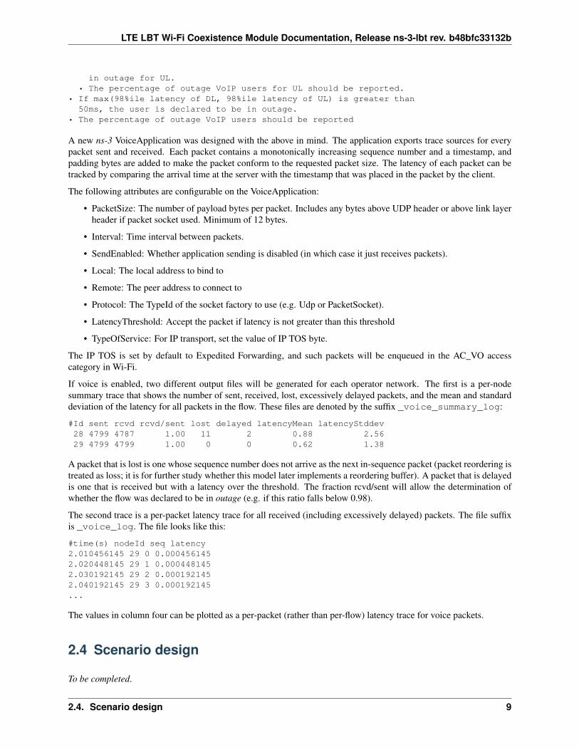
If voice is enabled, two different output files will be generated for each operator network. The first is a per-nodesummary trace that shows the number of sent, received, lost, excessively delayed packets, and the mean and standarddeviation of the latency for all packets in the flow. These files are denoted by the suffix _voice_summary_log:
#Id sent rcvd rcvd/sent lost delayed latencyMean latencyStddev28 4799 4787 1.00 11 2 0.88 2.5629 4799 4799 1.00 0 0 0.62 1.38
A packet that is lost is one whose sequence number does not arrive as the next in-sequence packet (packet reordering istreated as loss; it is for further study whether this model later implements a reordering buffer). A packet that is delayedis one that is received but with a latency over the threshold. The fraction rcvd/sent will allow the determination ofwhether the flow was declared to be in outage (e.g. if this ratio falls below 0.98).
The second trace is a per-packet latency trace for all received (including excessively delayed) packets. The file suffixis _voice_log. The file looks like this:
#time(s) nodeId seq latency2.010456145 29 0 0.0004561452.020448145 29 1 0.0004481452.030192145 29 2 0.0001921452.040192145 29 3 0.000192145...
The values in column four can be plotted as a per-packet (rather than per-flow) latency trace for voice packets.
2.4 Scenario design
To be completed.
2.4. Scenario design 9
LTE LBT Wi-Fi Coexistence Module Documentation, Release ns-3-lbt rev. b48bfc33132b
2.4.1 Simple scenario
2.4.2 Indoor scenario
2.4.3 Outdoor scenario
2.5 References
10 Chapter 2. Design
CHAPTER
THREE
USAGE
This section will provide overviews of some of the example programs, and describe how parameters can be controlledand changed, and what output is produced.
Please be aware that the LBT code is not mainline ns-3 code yet, and will be updated and aligned with the main treebefore it is officially supported by the project. This code is being made available to support others who want to getstarted with it in the meantime, and to support the reproduction of figures that have been included in some publicationsthat have been made using this code.
If you have questions about this code, you may email [email protected] forum (seehttps://www.nsnam.org/support/mailing-list/) and questions can be answered there on a best-effort basis.
3.1 Getting the LBT code
The LBT code is posted in a Mercurial repository on the main ns-3 code server (http://code.nsnam.org/laa/ns-3-lbt). If you are not familiar with Mercurial or how to fetch repositories, you will want to read the ns-3 Tutorial(https://www.nsnam.org/docs/release/3.24/tutorial/html/index.html). In any case, reading this tutorial is highly recom-mended before you try to use this code.
Briefly, using Mercurial on Linux or OS X (Windows native is not supported), you can try:
hg clone http://code.nsnam.org/laa/ns-3-lbt
You can also navigate your web browser to http://code.nsnam.org/laa/ns-3-lbt and click on one of the links at the topof the page labelled bz2, zip, or gz, to download an archive.
You should not try to use this code with some other ns-3 release. That is, if you try to copy thesrc/laa-wifi-coexistence directory into some other ns-3 release (such as ns-3.24/src) it will not workproperly and likely won’t compile.
3.2 Compiling the LBT code
Building ns-3 is out of scope for this documentation, but we provide a very quick guide for the impatient below. Ifa user is on a recent version of Linux, with g++ and Python installed, then the following commands should work,assuming the code is extracted to a directory called ns-3-lbt:
cd ns-3-lbt./waf configure -d optimized --enable-examples --enable-tests./waf build./test-lbt.py
There are three primary example programs supported, each with a wide number of configurable command-line options:
11
LTE LBT Wi-Fi Coexistence Module Documentation, Release ns-3-lbt rev. b48bfc33132b
1. laa-wifi-simple.cc
2. laa-wifi-indoor.cc
3. laa-wifi-outdoor.cc
By far, the most widely used example is laa-wifi-indoor so we will focus on its operation. The source code isfound in the file src/laa-wifi-coexistence/examples/laa-wifi-indoor.cc
3.3 Global Values
List all global values and what they do
3.4 Examples
Examples can be run directly from the command line, with arguments as needed. It is also possible to orchestrate therunning and plotting of data with shell scripts (described below in the Results section).
3.4.1 laa-wifi-simple.cc
To be completed
3.4.2 laa-wifi-indoor.cc
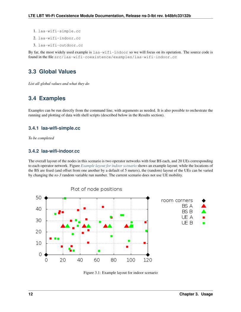
The overall layout of the nodes in this scenario is two operator networks with four BS each, and 20 UEs correspondingto each operator network. Figure Example layout for indoor scenario shows an example layout; while the locations ofthe BS are fixed (and offset from one another by a default of 5 meters), the (random) layout of the UEs can be variedby changing the ns-3 random variable run number. The current scenario does not use UE mobility.
Figure 3.1: Example layout for indoor scenario
12 Chapter 3. Usage
LTE LBT Wi-Fi Coexistence Module Documentation, Release ns-3-lbt rev. b48bfc33132b
To run the indoor scenario with defaults, execute the following command from the top-level ns-3-lbt directory:
./waf --run laa-wifi-indoor
3.4.3 laa-wifi-outdoor.cc
The example program laa-wifi-outdoor.cc is a carry-over from phase 1 and was not used in this phase, and ithasn’t been recently exercised or tested.
3.4. Examples 13
LTE LBT Wi-Fi Coexistence Module Documentation, Release ns-3-lbt rev. b48bfc33132b
14 Chapter 3. Usage
CHAPTER
FOUR
TESTS AND VALIDATION
In this section we first describe the calibration process followed to achieve comparable results from the Wi-Fi and LTEmodules. Then we describe the test suites that are provided, along with the code of the laa-wifi-coexistencemodule, in order to validate its proper functionality and correct simulation output in some key configurations for whichthe intended behavior and output can be determined a priori.
To be completed.
15
LTE LBT Wi-Fi Coexistence Module Documentation, Release ns-3-lbt rev. b48bfc33132b
16 Chapter 4. Tests and Validation
CHAPTER
FIVE
RESULTS
In this chapter we provide some initial simulation results obtained to evaluate coexistence of LTE and Wi-Fi. We firstdescribe the framework used to launch simulation campaigns and process the results. Then we present the resultsfor some selected scenarios, including the indoor and outdoor scenarios that have been defined based on the 3GPPTR36.889 document.
5.1 Scripted Indoor Scenario
In the directory src/laa-wifi-coexistence/experiments/laa-wifi-indoor-ftp there are twoscripts, run-laa-wifi-indoor-ftp.sh and plot-laa-wifi-indoor-ftp.sh. These are Bash scriptsthat orchestrate the running of the laa-wifi-indoor program across different parameter configurations, collectthe results into a results directory, and then parse the output to obtain CDFs that are plotted in gnuplot, with theresulting plots ending up in the images directory.
To run these scripts, first make sure that gnuplot is installed on your system. Then, execute therun-laa-wifi-indoor-ftp.sh program (which may take some time to execute), and then theplot-laa-wifi-indoor-ftp.sh program. If these scripts successfully complete, you should find both aresults and an images directory, and you should be able to open an image thumbnail page by opening the fileimages/thumbnails/index.html in a web browser.
In this section, we’ll walk through some sample results, starting with some images that are produced, and then lookingat the raw results directory and the script that orchestrates the simulation campaign.
Below are a few representative results that were fetched from the images/ps directory. There are two sets of threefigures each, corresponding to step 1 (Wi-Fi) and step 2 (LAA) simulation runs. Each set of three figures contains athroughput CDF, a latency CDF, and a voice latency CDF. They correspond to the use of an LAA energy detectionthreshold of -72 dBm, and an FTP lambda value of 2.5. The corresponding figures from the images/ directory arenamed:
• indoor_-72_0_ftpLambda_2_5_Wifi_throughput.eps
• indoor_-72_0_ftpLambda_2_5_Laa_throughput.eps
• indoor_-72_0_ftpLambda_2_5_Wifi_latency.eps
• indoor_-72_0_ftpLambda_2_5_Laa_latency.eps
• indoor_-72_0_ftpLambda_2_5_Wifi_voice_latency.eps
• indoor_-72_0_ftpLambda_2_5_Laa_voice_latency.eps
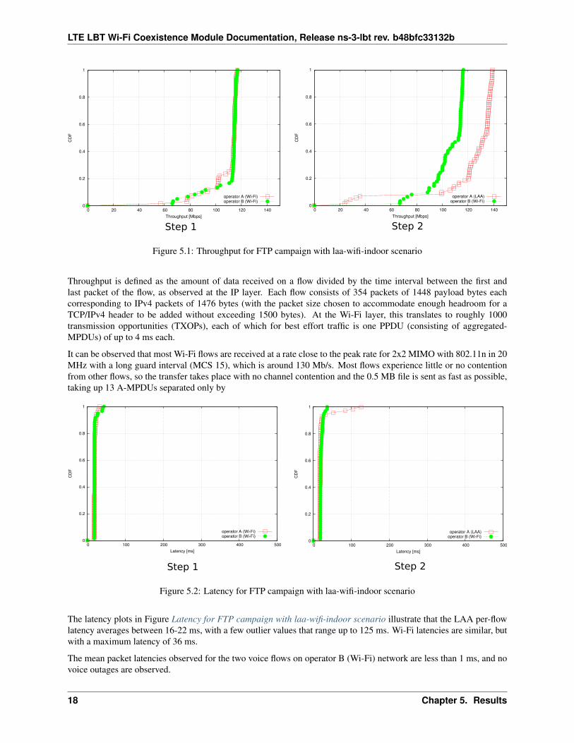
Figure Throughput for FTP campaign with laa-wifi-indoor scenario illustrates, on the left, the performance of 3GPPFTP over Wi-Fi (a so-called “step 1” network) and on the right, the same scenario with one Wi-Fi network replaced byan equivalent LAA network. The plot is a cumulative distribution function (CDF) of file transfer throughputs observedduring the simulation.
17
LTE LBT Wi-Fi Coexistence Module Documentation, Release ns-3-lbt rev. b48bfc33132b
0
0.2
0.4
0.6
0.8
1
0 20 40 60 80 100 120 140
CD
F
Throughput [Mbps]
operator A (Wi-Fi)operator B (Wi-Fi)
0
0.2
0.4
0.6
0.8
1
0 20 40 60 80 100 120 140
CD
F
Throughput [Mbps]
operator A (LAA)operator B (Wi-Fi)
Step 1 Step 2
Figure 5.1: Throughput for FTP campaign with laa-wifi-indoor scenario
Throughput is defined as the amount of data received on a flow divided by the time interval between the first andlast packet of the flow, as observed at the IP layer. Each flow consists of 354 packets of 1448 payload bytes eachcorresponding to IPv4 packets of 1476 bytes (with the packet size chosen to accommodate enough headroom for aTCP/IPv4 header to be added without exceeding 1500 bytes). At the Wi-Fi layer, this translates to roughly 1000transmission opportunities (TXOPs), each of which for best effort traffic is one PPDU (consisting of aggregated-MPDUs) of up to 4 ms each.
It can be observed that most Wi-Fi flows are received at a rate close to the peak rate for 2x2 MIMO with 802.11n in 20MHz with a long guard interval (MCS 15), which is around 130 Mb/s. Most flows experience little or no contentionfrom other flows, so the transfer takes place with no channel contention and the 0.5 MB file is sent as fast as possible,taking up 13 A-MPDUs separated only by
0
0.2
0.4
0.6
0.8
1
0 100 200 300 400 500
CD
F
Latency [ms]
operator A (Wi-Fi)operator B (Wi-Fi)
0
0.2
0.4
0.6
0.8
1
0 100 200 300 400 500
CD
F
Latency [ms]
operator A (LAA)operator B (Wi-Fi)
Step 1 Step 2
Figure 5.2: Latency for FTP campaign with laa-wifi-indoor scenario
The latency plots in Figure Latency for FTP campaign with laa-wifi-indoor scenario illustrate that the LAA per-flowlatency averages between 16-22 ms, with a few outlier values that range up to 125 ms. Wi-Fi latencies are similar, butwith a maximum latency of 36 ms.
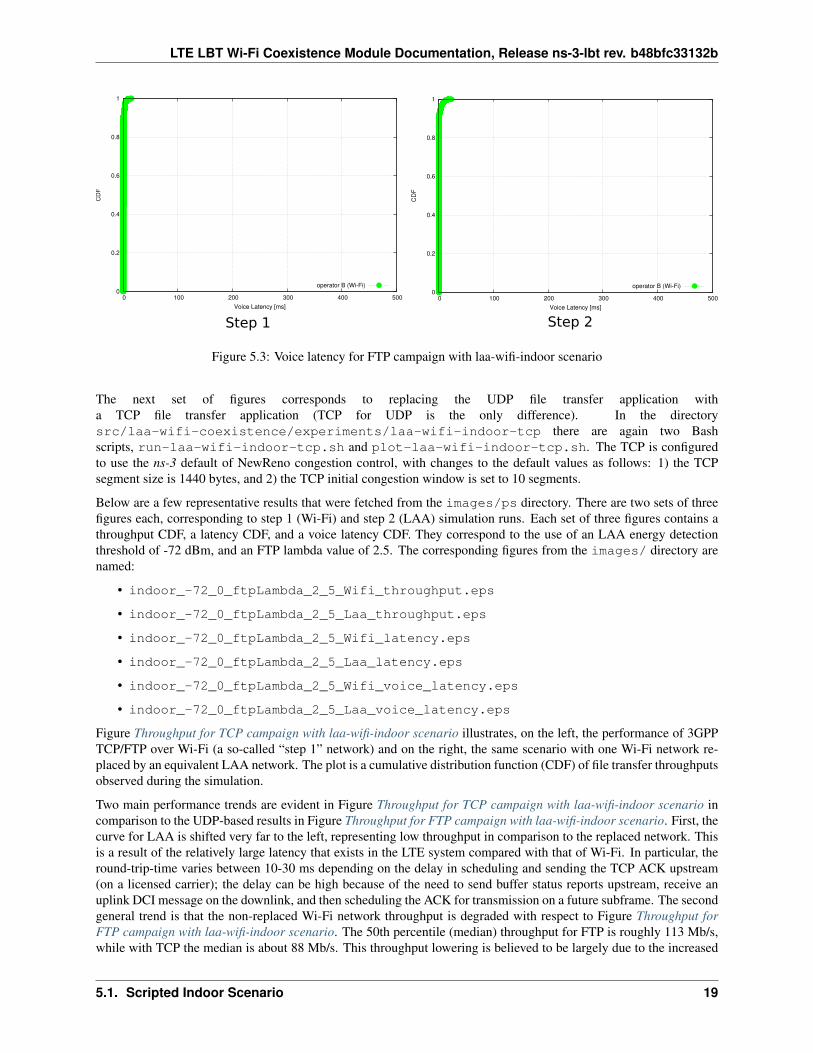
The mean packet latencies observed for the two voice flows on operator B (Wi-Fi) network are less than 1 ms, and novoice outages are observed.
18 Chapter 5. Results
LTE LBT Wi-Fi Coexistence Module Documentation, Release ns-3-lbt rev. b48bfc33132b
0
0.2
0.4
0.6
0.8
1
0 100 200 300 400 500
CD
F
Voice Latency [ms]
operator B (Wi-Fi)0
0.2
0.4
0.6
0.8
1
0 100 200 300 400 500
CD
F
Voice Latency [ms]
operator B (Wi-Fi)
Step 1 Step 2
Figure 5.3: Voice latency for FTP campaign with laa-wifi-indoor scenario
The next set of figures corresponds to replacing the UDP file transfer application witha TCP file transfer application (TCP for UDP is the only difference). In the directorysrc/laa-wifi-coexistence/experiments/laa-wifi-indoor-tcp there are again two Bashscripts, run-laa-wifi-indoor-tcp.sh and plot-laa-wifi-indoor-tcp.sh. The TCP is configuredto use the ns-3 default of NewReno congestion control, with changes to the default values as follows: 1) the TCPsegment size is 1440 bytes, and 2) the TCP initial congestion window is set to 10 segments.
Below are a few representative results that were fetched from the images/ps directory. There are two sets of threefigures each, corresponding to step 1 (Wi-Fi) and step 2 (LAA) simulation runs. Each set of three figures contains athroughput CDF, a latency CDF, and a voice latency CDF. They correspond to the use of an LAA energy detectionthreshold of -72 dBm, and an FTP lambda value of 2.5. The corresponding figures from the images/ directory arenamed:
• indoor_-72_0_ftpLambda_2_5_Wifi_throughput.eps
• indoor_-72_0_ftpLambda_2_5_Laa_throughput.eps
• indoor_-72_0_ftpLambda_2_5_Wifi_latency.eps
• indoor_-72_0_ftpLambda_2_5_Laa_latency.eps
• indoor_-72_0_ftpLambda_2_5_Wifi_voice_latency.eps
• indoor_-72_0_ftpLambda_2_5_Laa_voice_latency.eps
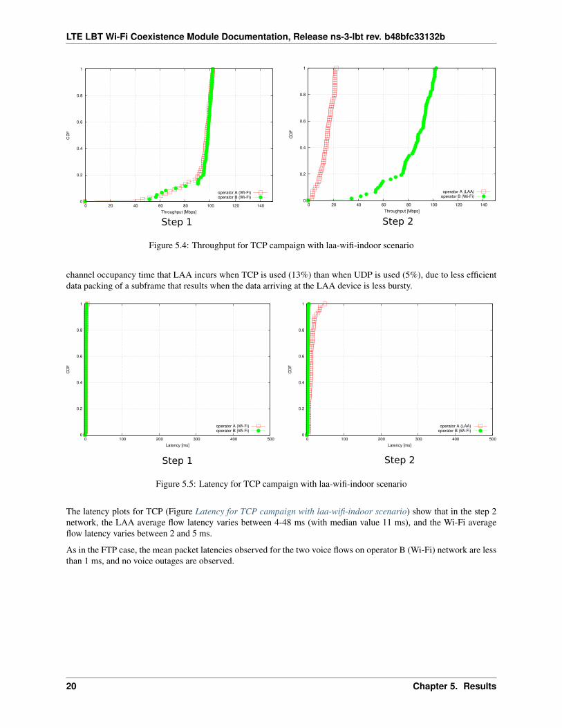
Figure Throughput for TCP campaign with laa-wifi-indoor scenario illustrates, on the left, the performance of 3GPPTCP/FTP over Wi-Fi (a so-called “step 1” network) and on the right, the same scenario with one Wi-Fi network re-placed by an equivalent LAA network. The plot is a cumulative distribution function (CDF) of file transfer throughputsobserved during the simulation.
Two main performance trends are evident in Figure Throughput for TCP campaign with laa-wifi-indoor scenario incomparison to the UDP-based results in Figure Throughput for FTP campaign with laa-wifi-indoor scenario. First, thecurve for LAA is shifted very far to the left, representing low throughput in comparison to the replaced network. Thisis a result of the relatively large latency that exists in the LTE system compared with that of Wi-Fi. In particular, theround-trip-time varies between 10-30 ms depending on the delay in scheduling and sending the TCP ACK upstream(on a licensed carrier); the delay can be high because of the need to send buffer status reports upstream, receive anuplink DCI message on the downlink, and then scheduling the ACK for transmission on a future subframe. The secondgeneral trend is that the non-replaced Wi-Fi network throughput is degraded with respect to Figure Throughput forFTP campaign with laa-wifi-indoor scenario. The 50th percentile (median) throughput for FTP is roughly 113 Mb/s,while with TCP the median is about 88 Mb/s. This throughput lowering is believed to be largely due to the increased
5.1. Scripted Indoor Scenario 19
LTE LBT Wi-Fi Coexistence Module Documentation, Release ns-3-lbt rev. b48bfc33132b
Step 1 Step 2
0
0.2
0.4
0.6
0.8
1
0 20 40 60 80 100 120 140
CD
F
Throughput [Mbps]
operator A (Wi-Fi)operator B (Wi-Fi)
0
0.2
0.4
0.6
0.8
1
0 20 40 60 80 100 120 140
CD
F
Throughput [Mbps]
operator A (LAA)operator B (Wi-Fi)
Figure 5.4: Throughput for TCP campaign with laa-wifi-indoor scenario
channel occupancy time that LAA incurs when TCP is used (13%) than when UDP is used (5%), due to less efficientdata packing of a subframe that results when the data arriving at the LAA device is less bursty.
Step 1 Step 2
0
0.2
0.4
0.6
0.8
1
0 100 200 300 400 500
CD
F
Latency [ms]
operator A (Wi-Fi)operator B (Wi-Fi)
0
0.2
0.4
0.6
0.8
1
0 100 200 300 400 500
CD
F
Latency [ms]
operator A (LAA)operator B (Wi-Fi)
Figure 5.5: Latency for TCP campaign with laa-wifi-indoor scenario
The latency plots for TCP (Figure Latency for TCP campaign with laa-wifi-indoor scenario) show that in the step 2network, the LAA average flow latency varies between 4-48 ms (with median value 11 ms), and the Wi-Fi averageflow latency varies between 2 and 5 ms.
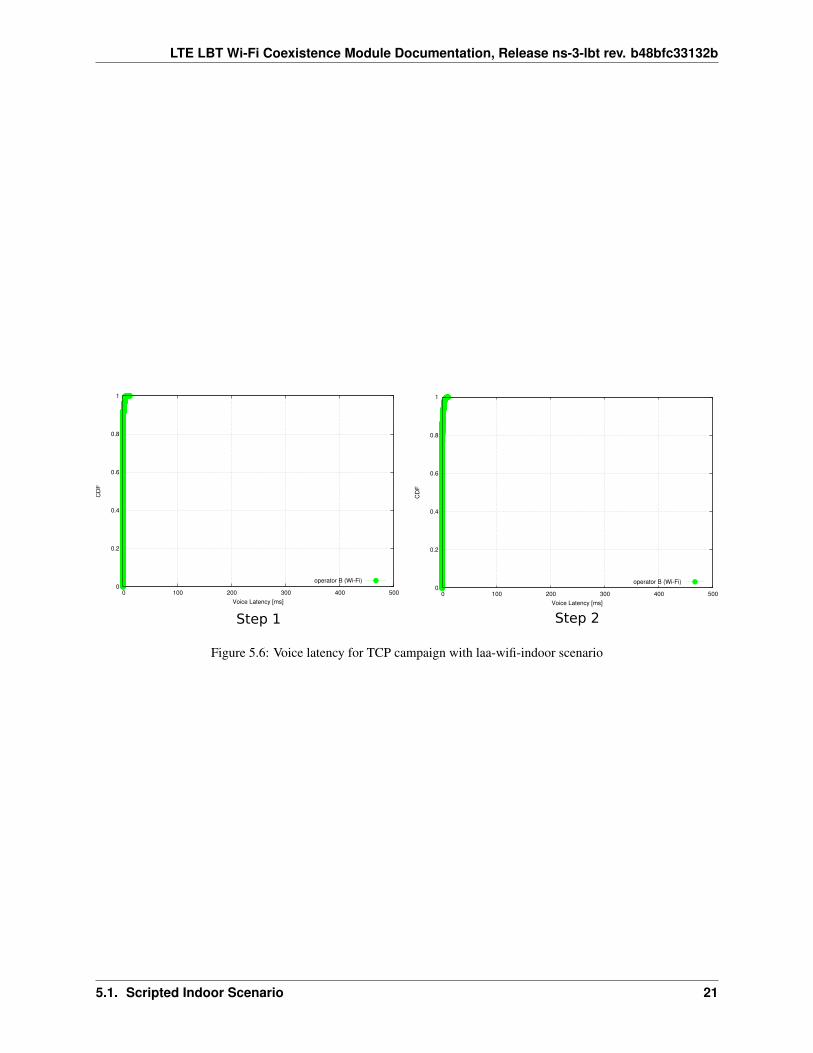
As in the FTP case, the mean packet latencies observed for the two voice flows on operator B (Wi-Fi) network are lessthan 1 ms, and no voice outages are observed.
20 Chapter 5. Results
LTE LBT Wi-Fi Coexistence Module Documentation, Release ns-3-lbt rev. b48bfc33132b
Step 1 Step 2
0
0.2
0.4
0.6
0.8
1
0 100 200 300 400 500
CD
F
Voice Latency [ms]
operator B (Wi-Fi)
0
0.2
0.4
0.6
0.8
1
0 100 200 300 400 500
CD
F
Voice Latency [ms]
operator B (Wi-Fi)
Figure 5.6: Voice latency for TCP campaign with laa-wifi-indoor scenario
5.1. Scripted Indoor Scenario 21
LTE LBT Wi-Fi Coexistence Module Documentation, Release ns-3-lbt rev. b48bfc33132b
22 Chapter 5. Results
CHAPTER
SIX
OPEN ISSUES AND FUTURE WORK
This section contains discussion regarding open issues with the current set of models and scenarios, or open questionsregarding interpretation of standards documents.
To be completed.
23
LTE LBT Wi-Fi Coexistence Module Documentation, Release ns-3-lbt rev. b48bfc33132b
24 Chapter 6. Open Issues and Future Work
BIBLIOGRAPHY
[TR36814] 3GPP TR 36.814 “Further advancements for E-UTRA physical layer aspects”, (Release 9) V9.0.0 (2010-03), 3rd Generation Partnership Project, 2010.
[TR36889] 3GPP TR 36.889 “Study on Licensed-Assisted Access to Unlicensed Spectrum”, (Release 13) TR36.889v13.0.0 (2015-06), 3rd Generation Partnership Project, 2015.
[RP-152233] 3GPP RP-152233, “Status Report to TSG, Work Item on Licensed-Assisted Access to Unlicensed Spec-trum, December 2015.
25