lpg 50e, 60e, & 80e, fanned balanced flue gas fired boilers · balanced flue gas fired boilers...
TRANSCRIPT
LPG 50e, 60e, & 80e, fannedbalanced flue gas fired boilers
THIS APPLIANCE IS FOR USE WITH PROPANE GAS (G31) ONLY
Installation and Servicing Instructions
LEAVE THESE INSTRUCTIONS ADJACENT TO THE APPLIANCE

12
GAD (90/396/EEC)
IMPORTANT This appliance must be installed and serviced by a competent person as stated in the Gas Safety (Installationand Use) Regulations 1994.
Profile LPG boilers have been designed to comply with the requirements of BS 5258 Part 1 and BS 6332 Part 1. It isimportant that no external control devices (e.g. flue dampers, economisers, etc.) be directly connected to these appliancesunless covered by these installation instructions or otherwise recommended in writing. Any direct connection of a controldevice not approved by Potterton could invalidate the normal warranty.
LIST OF CONTENTS - Page 2
General Page No. 2 Site Requirements Page No. 3Optional Extras Page No. 2 Technical Data Page No. 6Accessories Page No. 3 Installation Instructions Page No. 11Installation Data Page No. 3 Commissioning Page No. 18Boiler Dimensions Page No. 3 Servicing Instructions Page No. 21
Health and Safety Information Back PageControl Systems, Pipework andWiring Guide Supplied inUser’s Instructions Literature Pack
GENERAL - Page 2
Potterton Profile LPG boilers are fully automaticallycontrolled wall mounted fan powered balanced flueappliances, using a cast iron heat exchanger and areavailable in three outputs. 14.7 kW (50000 Btu/h), 17.6 kW(60000 Btu/h) and 23.44 kW (80000 Btu/h).
The boilers which are designed to provide domestic hotwater and/or central heating must be used on INDIRECThot water systems only. The cast iron heat exchangers aresuitable for use on open vented gravity domestic hotwater/pumped central heating systems or fully pumpedsystems which may be sealed or open vented.
All boilers can be supplied with either of the following typesof flue system:
1) Standard horizontal flue system suitable for wallthickness of 100mm (4 in.) to 510mm (20 in.).
2) 2 metre horizontal flue system which provides amaximum flue length of 1955mm (77 in.).
3) Vertical flue system which allows the flue to passthrough a flat roof and terminate at a maximum heightof 1980mm (78 in.) measured from the top of the boilercase.
OPTIONAL EXTRAS - Page 2
The following are kits available as optional extras:-
Internal Fitment Kit, which is suitable for a maximum wallthickness of 510mm (20 in.) is to be used where access tothe outside wall is impracticable.
Terminal Guard, to be used when the terminal is fitted lessthan 2m above a balcony, above ground or above a flat roofto which people have access.
Full fitting instructions are provided with each kit.
Pump Cover KIts, located on top of the boiler anddesigned to conceal the pump, and/or any motorised PART Nos
valves installed above the boiler. (Note: Pump cannot 5Oe 60e 80e
be fitted above the boiler if the vertical flue kit is used. Standard Flue system 225540 225541 225541
2 metre Flue System 225543 225544 225544
Terminal Wall Plate, where necessary can be fitted to Vertical Flue system 213074 213048 213049
the outside wall face to improve the appearance, after Terminal Wall Plate 212306 212280 212280
making good around the terminal. Terminal Guard 205792 205792 205792
Internal Fitment Kit 225183 225184 225184
Pump Cover Kit (6in) 225418 225418 225418
Pump cover Kit (71n - 12in) 225419 225419 225419
Pump Cover Kit (l3in - l8in) 225420 225420 225420
Pump Cover Kit (l9in - 24in) 225421 225421 225421
13
ACCESSORIES - Page 3
The following Potterton Myson controls are recommendedfor use with your boiler:- Electronic Programmer EP2001,
EP3001, or EP6000
Cylinder Thermostat PTT2 or PTT1 00
Room Thermostat PRT2 or PRT100
Frost Thermostat PRT1 00 FR
Motorised Zone Valve M5V222 or M5V228
Motorised Diverter Valve M5V322
Thermostatic Radiator Valve
Data Sheets describing these products are available onrequest.
INSTALLATION DATA - Page 3
The installation of the boiler must be in accordance with thelatest relevant requirements of the Gas Safety (Installationand Use) Regulations 1984, local building regulations, lEEWiring Regulations and the Byelaws of the Local WaterUndertaking.
Detailed recommendations are contained in the followingBritish Standards and Codes of Practice.
B55482 Part 1, B56798, B55440 Part 1, B55440
Part 2, BS5449 Part 1, B55546, BS4814.B56891 BUILDING REGULATIONS 1985.MODEL WATER BYELAWS.BRITISH GAS PUBLICATION DM2.GAS SAFETY (INSULATION AND USE) REGULATIONS1984.BUILDING STANDARDS (SCOTLAND) REGULATIONS
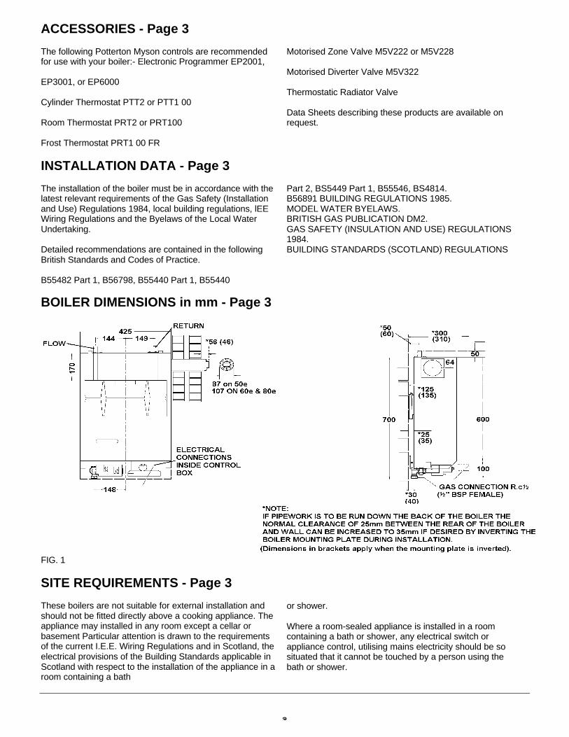
BOILER DIMENSIONS in mm - Page 3
FIG. 1
SITE REQUIREMENTS - Page 3
These boilers are not suitable for external installation andshould not be fitted directly above a cooking appliance. Theappliance may installed in any room except a cellar orbasement Particular attention is drawn to the requirementsof the current I.E.E. Wiring Regulations and in Scotland, theelectrical provisions of the Building Standards applicable inScotland with respect to the installation of the appliance in aroom containing a bath
or shower.
Where a room-sealed appliance is installed in a roomcontaining a bath or shower, any electrical switch orappliance control, utilising mains electricity should be sosituated that it cannot be touched by a person using thebath or shower.
SITE REQUIREMENTS - Page 4
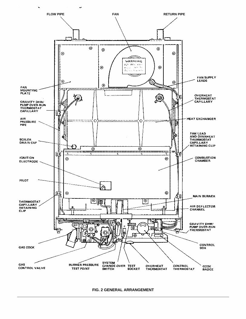
FLOW PIPE FAN RETURN PIPE
FIG. 2 GENERAL ARRANGEMENT

SITE REQUIREMENTS - Page 5
Where the installation of the boiler will be in an unusuallocation, special procedures may be necessary and BS6798 1987 gives detailed guidance on this aspect.Ensure that the gas supply pipe and meter if fitted areinstalled in accordance with B55482 Part 1. Check that theyare large enough for this appliance and any others that maybe run off the same supply. If in doubt seek advice from thePropane gas supplier.
Boiler Mounting SurfaceThe boiler must be mounted on a flat wall, which may be ofcombustible material and must be sufficiently robust to takethe weight of the boiler. The requirements of the localauthorities and the Building Regulations must be adheredto.
IMPORTANT NOTICE:TIMBER FRAMED HOUSES
If the appliance is to be fitted in a timber framed building, itshould be fitted in accordance with British Gas PublicationOperational Procedures for Customer Service’ Part 19. If in‘anydoubt, advice should be sought from the local region of BritishGas.
Clearances Around the BoilerThe following minimum clearances must be maintained afterinstallation, for correct operation and servicing of the boiler:
610mm (2 ft) at the front of the boiler
5mm (0.2 in) each side of the boiler
50mm (2 in) at the top (measured from the top of the boilercase), except where the optional extra pump cover is to befitted, when 178mm (7 in) should be allowed.100mm (4 in) at the bottom of the boiler.Additional clearances to these are required duringinstallation for lifting the boiler and 127mm (5 in) is requiredat the top of the boiler for access to the pipe connections.
VentilationIf the boiler is to be installed in a confined space such as acupboard, the space will need ventilating. Openings mustbe provided at the top and bottom of the cupboard each ofwhich should have a free area as shown in TABLE 1.Further details for installation of a boiler within acompartment are given in BS 6798 1987.
TABLE 1AIR VENT AREAS
PROFILEin2 cm2
50e 26 17060e 32 20680e 43 277
If the openings draw air from outside the building the freeareas may be halved. Refer to B55440 Part 2 for furtherguidance.
Balanced Flue Terminal and DuctingThe fresh air inlet and flue ducts can be run from either theleft, right, rear or top of the boiler to a miniature terminal onthe outside of the building.The minimum spacings from the terminal to obstructionsand ventilation openings are shown in FIG. 3. For infor-mation appertaining to horizontal flue lengths referenceshould be made to FIG. 4.If a terminal is fitted less than 2m above a balcony, aboveground or above a flat roof to which people have accessthen a suitable terminal guard should be fitted. (P.l.L. No.205792).Refer to B55440 Part 1 for further guidance.
INFORMATION RELATING TO VERTICAL FLUING ISPROVIDED IN THE PACK CONTAINING THE VERTICALFLUE SYSTEM.NOTEWhere a flue terminal is fitted less than 1000mm from aplastic or painted gutter or 500mm from painted eaves, analuminium shield of 1000mm length should befitted tounderside of gutter or eaves.Any car port or other add-on extension should consist of aroof or a roof and one other wall. If it consists of a roof andtwo other walls - the installation shall be treated as suspectand further advice sought.
FIG. 3 THE SITING OF BALANCED FLUE TERMINALS
Position Minimum Distancemm
A DIRECTLY BELOW AN OPENABLEWINDOW, AIR VENT, OR ANY OTHERVENTILATION OEPNING 300
B BELOW GUTTER, DRAIN/SOIL PIPE 25C BELOW EAVES 25D BELOW A BALCONY OR CAR PORT ROOF 25E FROM VERTICAL DRAIN PIPES AND SOIL
PIPES75
F FROM INTERNAL OR EXTERNALCORNERS
25
G ABOVE ADJACENT GROUND ORBALCONY LEVEL
300
H FROM A SURFACE FACING THETERMINAL
600
I FACING TERMINALS 1,200J. FROM OPENING (DOOR/WINDOW) IN
CARPORT INTO DWELLING 1,200K. VERTICALLY FROM A TERMINAL ON THE
SAME WALL 1,500L. HORIZONTALLY FROM A TERMINAL ON
THE SAME WALL 300M. ADJACENT TO OPENING 150
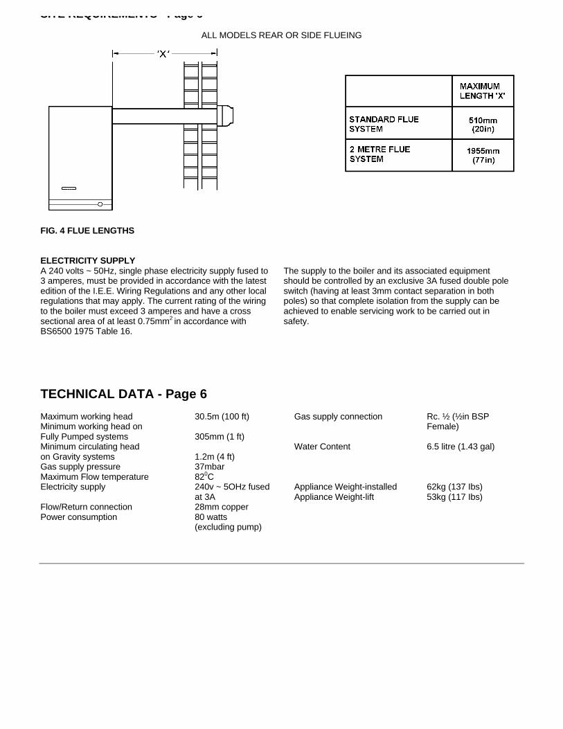
SITE REQUIREMENTS - Page 6
ALL MODELS REAR OR SIDE FLUEING
FIG. 4 FLUE LENGTHS
ELECTRICITY SUPPLYA 240 volts ~ 50Hz, single phase electricity supply fused to3 amperes, must be provided in accordance with the latestedition of the I.E.E. Wiring Regulations and any other localregulations that may apply. The current rating of the wiringto the boiler must exceed 3 amperes and have a crosssectional area of at least 0.75mm2 in accordance withBS6500 1975 Table 16.
The supply to the boiler and its associated equipmentshould be controlled by an exclusive 3A fused double poleswitch (having at least 3mm contact separation in bothpoles) so that complete isolation from the supply can beachieved to enable servicing work to be carried out insafety.
TECHNICAL DATA - Page 6
Maximum working head 30.5m (100 ft) Gas supply connection Rc. ½ (½in BSPMinimum working head on Female)Fully Pumped systems 305mm (1 ft)Minimum circulating head Water Content 6.5 litre (1.43 gal)on Gravity systems 1.2m (4 ft)Gas supply pressure 37mbarMaximum Flow temperature 820CElectricity supply 240v ~ 5OHz fused Appliance Weight-installed 62kg (137 Ibs)
at 3A Appliance Weight-lift 53kg (117 Ibs)Flow/Return connection 28mm copperPower consumption 80 watts
(excluding pump)
TECHNICAL DATA - Page 7
BOILERSIZE
INJECTORSIZE
GAS RATE at95.01- MJ/m3
(2500 Btu/ft3
M3/H (ft 3/h)
INPUT Kw(Btu/h)
OUTPUTkW(Btu/h)
BURNERPRESSURE
SUPPLYPRESSURE
50e 2.2mm 0.72 (25.6) 18.75 (64.000) 14.65(50000) 35.6(14.3) 37(14.8)
60e 2.4mm 0.87 (30.8) 22.56 (77.000) 17.6(60000) 35.3(14.2) 37(14.8)
80e 2.8mm 1.17 (41.2) 30.25 (103,000) 23.44(80000) 34.2(13.7) 37(14.8)
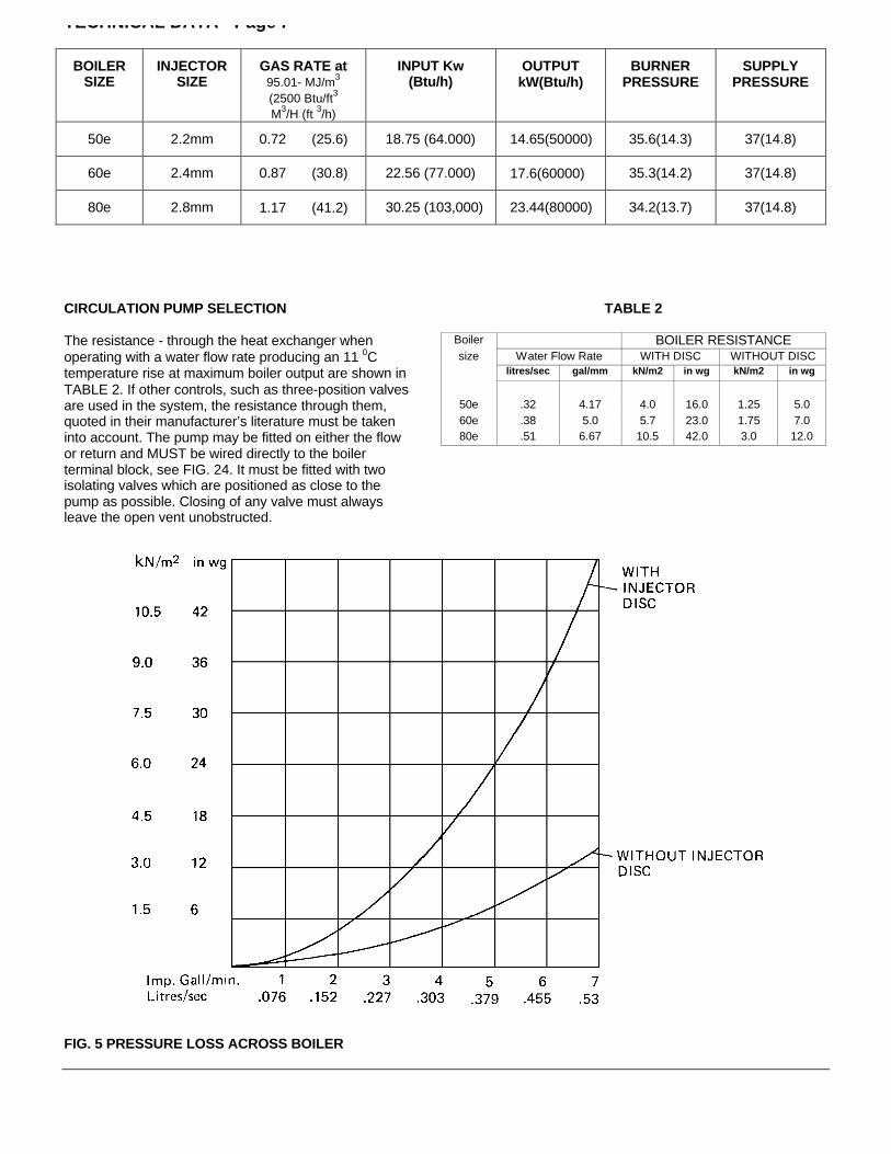
CIRCULATION PUMP SELECTION TABLE 2
The resistance - through the heat exchanger when Boiler BOILER RESISTANCEoperating with a water flow rate producing an 11 0C size Water Flow Rate WITH DISC WITHOUT DISC
temperature rise at maximum boiler output are shown in litres/sec gal/mm kN/m2 in wg kN/m2 in wg
TABLE 2. If other controls, such as three-position valvesare used in the system, the resistance through them, 50e .32 4.17 4.0 16.0 1.25 5.0
quoted in their manufacturer’s literature must be taken 60e .38 5.0 5.7 23.0 1.75 7.0
into account. The pump may be fitted on either the flow 80e .51 6.67 10.5 42.0 3.0 12.0
or return and MUST be wired directly to the boilerterminal block, see FIG. 24. It must be fitted with twoisolating valves which are positioned as close to thepump as possible. Closing of any valve must alwaysleave the open vent unobstructed.
FIG. 5 PRESSURE LOSS ACROSS BOILER
TECHNICAL DATA - Page 8
The System
The boiler must be used on INDIRECT hot water systems only.It is suitable for use on open vented gravity domestic hotwater/pumped central heating systems or, fully pumpedsystems which may be sealed or open vented.
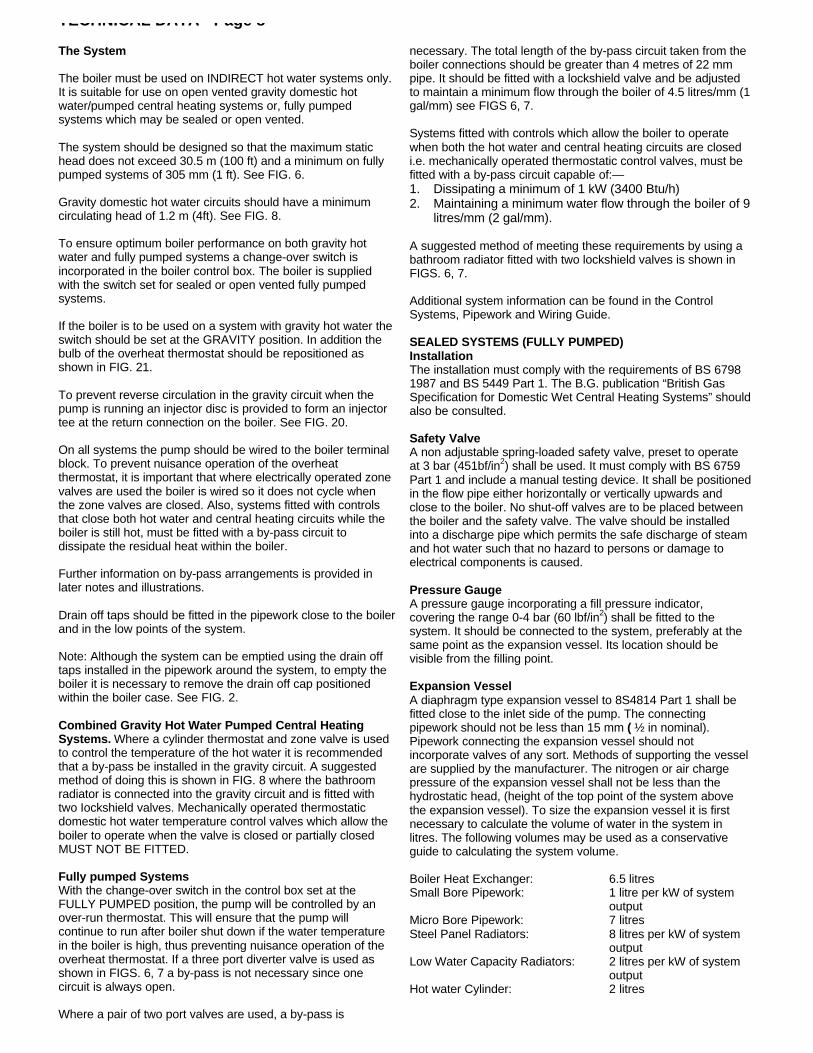
The system should be designed so that the maximum statichead does not exceed 30.5 m (100 ft) and a minimum on fullypumped systems of 305 mm (1 ft). See FIG. 6.
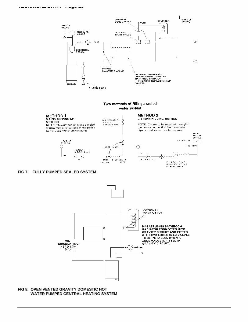
Gravity domestic hot water circuits should have a minimumcirculating head of 1.2 m (4ft). See FIG. 8.
To ensure optimum boiler performance on both gravity hotwater and fully pumped systems a change-over switch isincorporated in the boiler control box. The boiler is suppliedwith the switch set for sealed or open vented fully pumpedsystems.
If the boiler is to be used on a system with gravity hot water theswitch should be set at the GRAVITY position. In addition thebulb of the overheat thermostat should be repositioned asshown in FIG. 21.
To prevent reverse circulation in the gravity circuit when thepump is running an injector disc is provided to form an injectortee at the return connection on the boiler. See FIG. 20.
On all systems the pump should be wired to the boiler terminalblock. To prevent nuisance operation of the overheatthermostat, it is important that where electrically operated zonevalves are used the boiler is wired so it does not cycle whenthe zone valves are closed. Also, systems fitted with controlsthat close both hot water and central heating circuits while theboiler is still hot, must be fitted with a by-pass circuit todissipate the residual heat within the boiler.
Further information on by-pass arrangements is provided inlater notes and illustrations.
Drain off taps should be fitted in the pipework close to the boilerand in the low points of the system.
Note: Although the system can be emptied using the drain offtaps installed in the pipework around the system, to empty theboiler it is necessary to remove the drain off cap positionedwithin the boiler case. See FIG. 2.
Combined Gravity Hot Water Pumped Central HeatingSystems. Where a cylinder thermostat and zone valve is usedto control the temperature of the hot water it is recommendedthat a by-pass be installed in the gravity circuit. A suggestedmethod of doing this is shown in FIG. 8 where the bathroomradiator is connected into the gravity circuit and is fitted withtwo Iockshield valves. Mechanically operated thermostaticdomestic hot water temperature control valves which allow theboiler to operate when the valve is closed or partially closedMUST NOT BE FITTED.
Fully pumped SystemsWith the change-over switch in the control box set at theFULLY PUMPED position, the pump will be controlled by anover-run thermostat. This will ensure that the pump willcontinue to run after boiler shut down if the water temperaturein the boiler is high, thus preventing nuisance operation of theoverheat thermostat. If a three port diverter valve is used asshown in FIGS. 6, 7 a by-pass is not necessary since onecircuit is always open.
Where a pair of two port valves are used, a by-pass is
necessary. The total length of the by-pass circuit taken from theboiler connections should be greater than 4 metres of 22 mmpipe. It should be fitted with a lockshield valve and be adjustedto maintain a minimum flow through the boiler of 4.5 litres/mm (1gal/mm) see FIGS 6, 7.
Systems fitted with controls which allow the boiler to operatewhen both the hot water and central heating circuits are closedi.e. mechanically operated thermostatic control valves, must befitted with a by-pass circuit capable of:—1. Dissipating a minimum of 1 kW (3400 Btu/h)2. Maintaining a minimum water flow through the boiler of 9
litres/mm (2 gal/mm).
A suggested method of meeting these requirements by using abathroom radiator fitted with two lockshield valves is shown inFIGS. 6, 7.
Additional system information can be found in the ControlSystems, Pipework and Wiring Guide.
SEALED SYSTEMS (FULLY PUMPED)InstallationThe installation must comply with the requirements of BS 67981987 and BS 5449 Part 1. The B.G. publication “British GasSpecification for Domestic Wet Central Heating Systems” shouldalso be consulted.
Safety ValveA non adjustable spring-loaded safety valve, preset to operateat 3 bar (451bf/in2) shall be used. It must comply with BS 6759Part 1 and include a manual testing device. It shall be positionedin the flow pipe either horizontally or vertically upwards andclose to the boiler. No shut-off valves are to be placed betweenthe boiler and the safety valve. The valve should be installedinto a discharge pipe which permits the safe discharge of steamand hot water such that no hazard to persons or damage toelectrical components is caused.
Pressure GaugeA pressure gauge incorporating a fill pressure indicator,covering the range 0-4 bar (60 lbf/in2) shall be fitted to thesystem. It should be connected to the system, preferably at thesame point as the expansion vessel. Its location should bevisible from the filling point.
Expansion VesselA diaphragm type expansion vessel to 8S4814 Part 1 shall befitted close to the inlet side of the pump. The connectingpipework should not be less than 15 mm ( ½ in nominal).Pipework connecting the expansion vessel should notincorporate valves of any sort. Methods of supporting the vesselare supplied by the manufacturer. The nitrogen or air chargepressure of the expansion vessel shall not be less than thehydrostatic head, (height of the top point of the system abovethe expansion vessel). To size the expansion vessel it is firstnecessary to calculate the volume of water in the system inlitres. The following volumes may be used as a conservativeguide to calculating the system volume.
Boiler Heat Exchanger: 6.5 litresSmall Bore Pipework: 1 litre per kW of system
outputMicro Bore Pipework: 7 litresSteel Panel Radiators: 8 litres per kW of system
outputLow Water Capacity Radiators: 2 litres per kW of system
outputHot water Cylinder: 2 litres
TECHNICAL DATA - Page 9
If the system is extended, the expansion vessel volume mayhave to be increased unless previous provision has beenmade for the extension. Where a vessel of the calculatedsize is not available, the next available larger size should beused.The boiler flow temperature is controlled at approximately820C.The vessel size can now be determined from the followingtable where V=System volume in litres.
Method of Make-UpProvision shall be made for replacing water loss from thesystem either:—i) from a make-up vessel or tank mounted in a position
higher than the top point of the system, and connectedthrough a non-return valve to the system on the returnside of hot water cylinder or the return side of all heatemitters.or
ii) where access to a make-up vessel would be difficultVessel Charge Pressure(bar) 0.5 1.0 by using the mains top up method or a remote
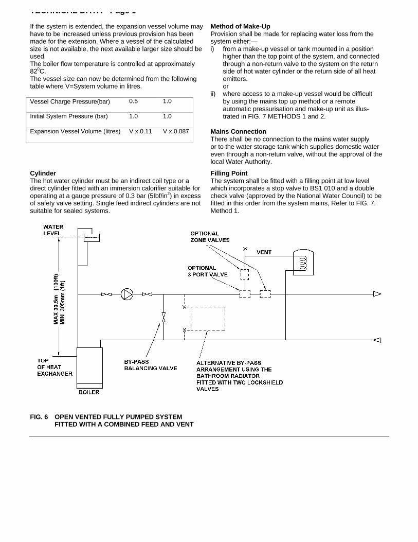
automatic pressurisation and make-up unit as illus-Initial System Pressure (bar) 1.0 1.0 trated in FIG. 7 METHODS 1 and 2.
Expansion Vessel Volume (litres) V x 0.11 V x 0.087 Mains ConnectionThere shall be no connection to the mains water supplyor to the water storage tank which supplies domestic watereven through a non-return valve, without the approval of thelocal Water Authority.
CylinderThe hot water cylinder must be an indirect coil type or adirect cylinder fitted with an immersion calorifier suitable foroperating at a gauge pressure of 0.3 bar (5Ibf/in2) in excessof safety valve setting. Single feed indirect cylinders are notsuitable for sealed systems.
Filling PointThe system shall be fitted with a filling point at low levelwhich incorporates a stop valve to BS1 010 and a doublecheck valve (approved by the National Water Council) to befitted in this order from the system mains, Refer to FIG. 7.Method 1.
FIG. 6 OPEN VENTED FULLY PUMPED SYSTEMFITTED WITH A COMBINED FEED AND VENT
TECHNICAL DATA - Page 10
FIG 7. FULLY PUMPED SEALED SYSTEM
FIG 8. OPEN VENTED GRAVITY DOMESTIC HOTWATER PUMPED CENTRAL HEATING SYSTEM
INSTALLATION INSTRUCTIONS - Page 11
It is the law that all gas appliances are installed andserviced by competent persons as stated in Gas Safety(Installation and Use) Regulations 1994.For Health and Safety information see back page.
Electrical installation and servicing should be carried out bya competent person in accordance with the I.E.E. WiringRegulations.
The boiler and its associated equipment will arrive on site intwo cardboard cartons. The contents of each carton is asfollows.
CARTON 1:- Boiler PackBoilerTemplateLiterature Pack Containing:-
Installation and Servicing InstructionsUser’s Instructions
Control Systems Pipework and Wiring GuideAuxiliary Pack Containing:-
Boiler Mounting BracketGas Service Cock and Accessory Packs
CARTON 2:- Flue System PackStandard and 2 metre Horizontal Flue Packs
Air/Flue Duct Assembly (length as ordered)Flue Elbow ExtensionFlue TerminalFlue Sealing CollarRope Sealing RingSide Infill Panels-2 off
Vertical Flue Pack (2 cartons)Air/Flue Duct Assembly Flue TerminalTerminal CowlVertical Flue AdapterAccessory PackSide Infill Panels-2 offFlue Installation Instructions
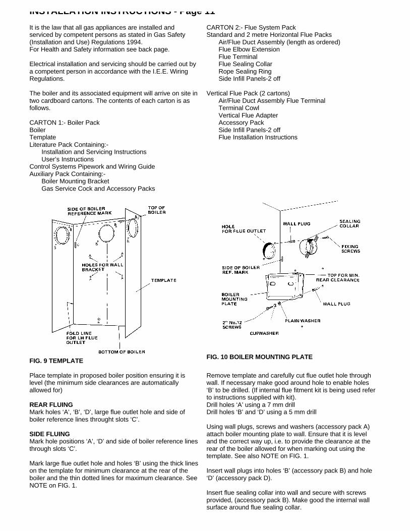
FIG. 9 TEMPLATEFIG. 10 BOILER MOUNTING PLATE
Place template in proposed boiler position ensuring it islevel (the minimum side clearances are automaticallyallowed for)
REAR FLUINGMark holes ‘A’, ‘B’, ‘D’, large flue outlet hole and side ofboiler reference lines throught slots ‘C’.
SIDE FLUINGMark hole positions ‘A’, ‘D’ and side of boiler reference linesthrough slots ‘C’.
Mark large flue outlet hole and holes ‘B’ using the thick lineson the template for minimum clearance at the rear of theboiler and the thin dotted lines for maximum clearance. SeeNOTE on FIG. 1.
Remove template and carefully cut flue outlet hole throughwall. If necessary make good around hole to enable holes‘B’ to be drilled. (If internal flue fitment kit is being used referto instructions supplied with kit).Drill holes ‘A’ using a 7 mm drillDrill holes ‘B’ and ‘D’ using a 5 mm drill
Using wall plugs, screws and washers (accessory pack A)attach boiler mounting plate to wall. Ensure that it is leveland the correct way up, i.e. to provide the clearance at therear of the boiler allowed for when marking out using thetemplate. See also NOTE on FIG. 1.
Insert wall plugs into holes ‘B’ (accessory pack B) and hole‘D’ (accessory pack D).
Insert flue sealing collar into wall and secure with screwsprovided, (accessory pack B). Make good the internal wallsurface around flue sealing collar.
INSTALLATION INSTRUCTIONS - Page 12
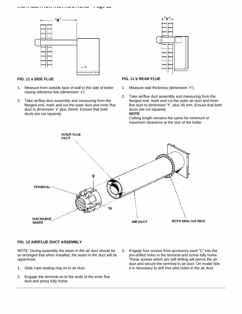
FIG. 11 a SIDE FLUE FIG. 11 b REAR FLUE
1. Measure from outside face of wall to the side of boilercasing reference line (dimension ‘x’).
2. Take air/flue duct assembly and measuring from theflanged end, mark and cut the outer duct and inner flueduct to dimension ‘x’ plus 20mm. Ensure that bothducts are cut squarely.
1. Measure wall thickness (dimension ‘Y’).
2. Take air/flue duct assembly and measuring from theflanged end, mark and cut the outer air duct and innerflue duct to dimension ‘Y’, plus 45 mm. Ensure that bothducts are cut squarely.NOTECutting length remains the same for minimum ormaximum clearance at the rear of the boiler
FIG. 12 AIR/FLUE DUCT ASSEMBLY
NOTE: During assembly the seam in the air duct should beso arranged that when installed, the seam in the duct will beuppermost.
1. Slide rope sealing ring on to air duct.
2. Engage the terminal on to the ends of the inner flueduct and press fully home.
3. Engage four screws from accessory pack “C” into thepre-drilled holes in the terminal and screw fully home.These screws which are self drilling will pierce the airduct and secure the terminal to air duct. On model 50eit is necessary to drill four pilot holes in the air duct.
INSTALLATION INSTRUCTIONS - Page 13
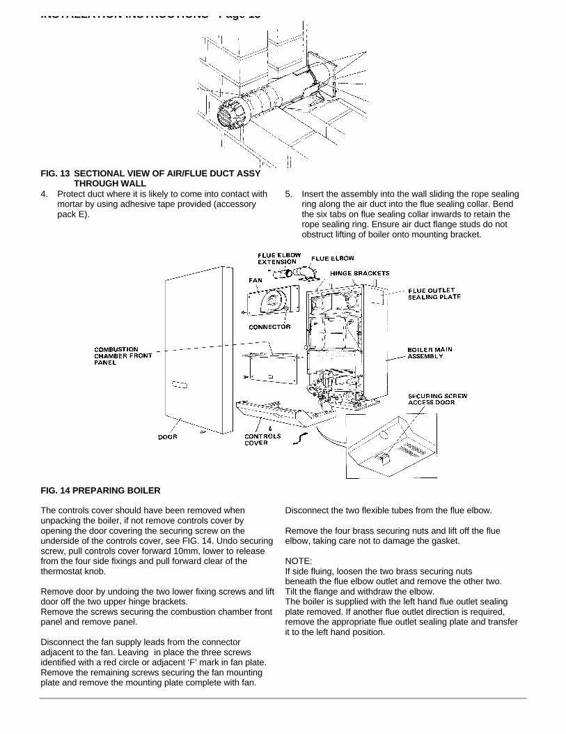
FIG. 13 SECTIONAL VIEW OF AIR/FLUE DUCT ASSYTHROUGH WALL
4. Protect duct where it is likely to come into contact withmortar by using adhesive tape provided (accessorypack E).
5. Insert the assembly into the wall sliding the rope sealingring along the air duct into the flue sealing collar. Bendthe six tabs on flue sealing collar inwards to retain therope sealing ring. Ensure air duct flange studs do notobstruct lifting of boiler onto mounting bracket.
FIG. 14 PREPARING BOILER
The controls cover should have been removed whenunpacking the boiler, if not remove controls cover byopening the door covering the securing screw on theunderside of the controls cover, see FIG. 14. Undo securingscrew, pull controls cover forward 10mm, lower to releasefrom the four side fixings and pull forward clear of thethermostat knob.
Remove door by undoing the two lower fixing screws and liftdoor off the two upper hinge brackets.Remove the screws securing the combustion chamber frontpanel and remove panel.
Disconnect the fan supply leads from the connectoradjacent to the fan. Leaving in place the three screwsidentified with a red circle or adjacent ‘F’ mark in fan plate.Remove the remaining screws securing the fan mountingplate and remove the mounting plate complete with fan.
Disconnect the two flexible tubes from the flue elbow.
Remove the four brass securing nuts and lift off the flueelbow, taking care not to damage the gasket.
NOTE:If side fluing, loosen the two brass securing nutsbeneath the flue elbow outlet and remove the other two.Tilt the flange and withdraw the elbow.The boiler is supplied with the left hand flue outlet sealingplate removed. If another flue outlet direction is required,remove the appropriate flue outlet sealing plate and transferit to the left hand position.

INSTALLATION INSTRUCTIONS - Page 14LIFTING THE BOILER
Lift the boiler onto its mounting bracket.
FIG. 15
FIG. 16 TRANSPORTATION FOOT
Locate the studs on the air duct flange through the boilercasing and secure using four wing nuts (accessory packF).
Position boiler on its mounting bracket so that the sides ofthe boiler line up with the reference lines ‘C’ on the rearwall.
Undo the two screws securing the transportation foot anddiscard foot. Vertical alignment with rear wall can becorrected using the adjustment screws at the rear of theboiler. See FIGS. 16 & 17.
FIG. 17 SECURING BOILER
FIG. 18 FLUE ELBOW EXTENSION
Rotate the left hand adjustment screw to align one of theholes in the base plate with hole ‘D’ in the wall. Workingthrough the hole in the leg, secure the base plate to the wallusing the screw from accessory pack D. Make good the wallsurface around the flue terminal. Fit optional terminal wallplate if required.
When side fluing, slide the elbow extension onto the elbowand ensure that it is pushed on fully. Engage the screw fromaccessory pack ‘C’ into the pre-drilled hole in the elbowextension and screw fully home. The screw which is selfdrilling will pierce the elbow and secure the extension to theelbow.
When rear fluing, the elbow extension should be discarded.
INSTALLATION INSTRUCTIONS - Page 15
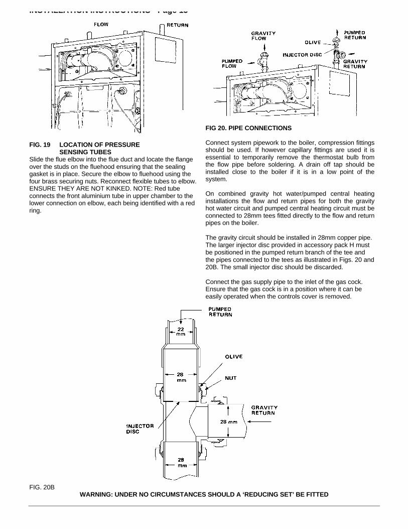
FIG. 19 LOCATION OF PRESSURESENSING TUBES
Slide the flue elbow into the flue duct and locate the flangeover the studs on the fluehood ensuring that the sealinggasket is in place. Secure the elbow to fluehood using thefour brass securing nuts. Reconnect flexible tubes to elbow.ENSURE THEY ARE NOT KINKED. NOTE: Red tubeconnects the front aluminium tube in upper chamber to thelower connection on elbow, each being identified with a redring.
FIG 20. PIPE CONNECTIONS
Connect system pipework to the boiler, compression fittingsshould be used. If however capillary fittings are used it isessential to temporarily remove the thermostat bulb fromthe flow pipe before soldering. A drain off tap should beinstalled close to the boiler if it is in a low point of thesystem.
On combined gravity hot water/pumped central heatinginstallations the flow and return pipes for both the gravityhot water circuit and pumped central heating circuit must beconnected to 28mm tees fitted directly to the flow and returnpipes on the boiler.
The gravity circuit should be installed in 28mm copper pipe.The larger injector disc provided in accessory pack H mustbe positioned in the pumped return branch of the tee andthe pipes connected to the tees as illustrated in Figs. 20 and20B. The small injector disc should be discarded.
Connect the gas supply pipe to the inlet of the gas cock.Ensure that the gas cock is in a position where it can beeasily operated when the controls cover is removed.
FIG. 20BWARNING: UNDER NO CIRCUMSTANCES SHOULD A ‘REDUCING SET’ BE FITTED
INSTALLATION INSTRUCTIONS - Page 16
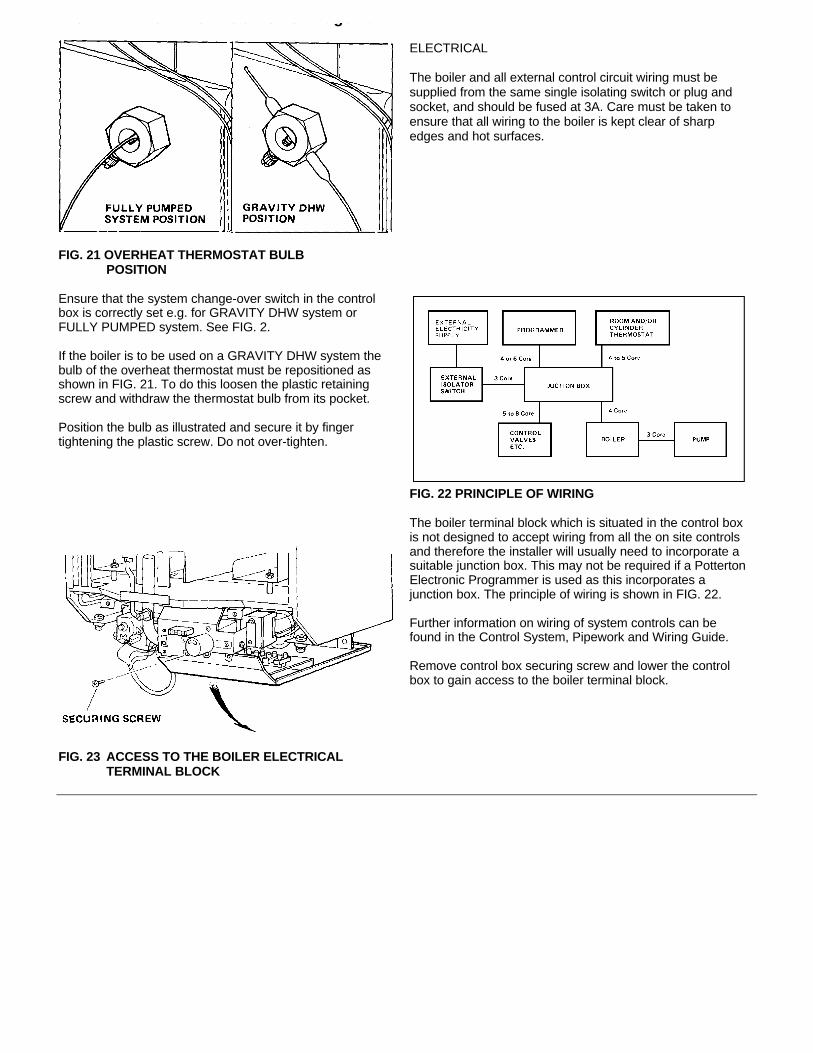
FIG. 21 OVERHEAT THERMOSTAT BULBPOSITION
ELECTRICAL
The boiler and all external control circuit wiring must besupplied from the same single isolating switch or plug andsocket, and should be fused at 3A. Care must be taken toensure that all wiring to the boiler is kept clear of sharpedges and hot surfaces.
Ensure that the system change-over switch in the controlbox is correctly set e.g. for GRAVITY DHW system orFULLY PUMPED system. See FIG. 2.
If the boiler is to be used on a GRAVITY DHW system thebulb of the overheat thermostat must be repositioned asshown in FIG. 21. To do this loosen the plastic retainingscrew and withdraw the thermostat bulb from its pocket.
Position the bulb as illustrated and secure it by fingertightening the plastic screw. Do not over-tighten.
FIG. 22 PRINCIPLE OF WIRING
FIG. 23 ACCESS TO THE BOILER ELECTRICALTERMINAL BLOCK
The boiler terminal block which is situated in the control boxis not designed to accept wiring from all the on site controlsand therefore the installer will usually need to incorporate asuitable junction box. This may not be required if a PottertonElectronic Programmer is used as this incorporates ajunction box. The principle of wiring is shown in FIG. 22.
Further information on wiring of system controls can befound in the Control System, Pipework and Wiring Guide.
Remove control box securing screw and lower the controlbox to gain access to the boiler terminal block.
INSTALLATION INSTRUCTIONS - Page 17
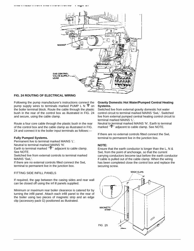
FIG. 24 ROUTING OF ELECTRICAL WIRING
Following the pump manufacturer’s instructions connect thepump supply wires to terminals marked PUMP L N onthe boiler terminal block. Route the cable through the plasticbush in the rear of the control box as illustrated in FIG. 24and secure, using the cable clamp.
Route a four core cable through the plastic bush in the rearof the control box and the cable clamp as illustrated in FIG.24 and connect it to the boiler input terminals as follows:—
Fully Pumped Systems.Permanent live to terminal marked MAINS ‘L’.Neutral to terminal marked MAINS ‘N’.Earth to terminal marked ‘ ’ adjacent to cable clamp.See NOTE.Switched live from external controls to terminal markedMAINS ‘SwL’.If there are no external controls filled connect the SwLterminal to permanent live in the junction box.
Gravity Domestic Hot Water/Pumped Central HeatingSystems.Switched live from external gravity domestic hot watercontrol circuit to terminal marked MAINS ‘SwL’. Switchedlive from external pumped central heating control circuit toterminal marked MAINS ‘L’.Neutral to terminal marked MAINS ‘N’. Earth to terminalmarked ‘ ’ adjacent to cable clamp. See NOTE.
If there are no external controls fitted connect the SwLterminal to permanent live in the junction box.
NOTE:Ensure that the earth conductor is longer than the L, N &SwL from the point of anchorage, so that the currentcarrying conductors become taut before the earth conductorif cable is pulled out of the cable clamp. When the wiringhas been completed close the control box and replace thesecuring screw.
FITTING SIDE INFILL PANELS
If required, the gap between the casing sides and rear wallcan be closed off using the inf ill panels supplied.
Minimum or maximum rear boiler clearance is catered for byturning the infill panel. Attach each infill panel to the rear ofthe boiler using two pieces of magnetic strip and an edgeclip (accessory pack G) positioned as illustrated.

COMMISSIONING - Page 18
Open Vented SystemsRemove the pump and flush out the system thoroughly withcold water. Refit the pump. Fill and vent the system.Examine for leaks.
Sealed SystemsNOTE:The system can be filled using a sealed system filler pumpwith a break tank or by any other method approved by theLocal Water Authority. Refer to ‘THE SYSTEM’ sectionPage 8 in these instructions, also BS 6798.
Remove pump and flush out the system thoroughly withcold water. Refit the pump. Fill and vent the system until thepressure gauge registers 1.5 bar (21.5 lbf/in2). Examine forleaks. Raise the pressure until the safety valve lifts. Thisshould occur within 1 0.3 bar of the preset lift pressure of 3bar. Release water to attain the correct cold fill pressure.
All SystemsRefit the fan assembly and reconnect the fan supply leads,(polarity of the fan leads is not important).
The whole of the gas installation including the meter (iffitted) should be inspected and tested for soundness andpurged in accordance with the recommendations of B55482Part 1.
Test pilot unions for gas soundness as follows:—Turn boiler thermostat to the ‘0’ position.
Unplug the gas control valve supply lead from the controlbox and plug it into the test socket adjacent to the boilerthermostat knob, see FIG. 24.
Turn on gas at the gas service cock.
Ensure that the time control if fitted is in an ON condition,and that the room and/or cylinder thermostats where fittedare set to high temperatures.
Switch on the external electricity supply to the boiler.Gas will flow to the pilot only. It will not be ignited as theignition system is de-energised.
Using a leak detection fluid, check pilot unions for gassoundness.
Turn off the external electicity supply and gas service cock.Remove gas control valve plug from the test socket and refitthe plug into the socket on the left hand side of the controlbox see FIG. 24.
Refit the combustion chamber front panel.Fit the case door into position by lifting it onto the top hingebrackets and secure it with the lower two fixing screws.
ENSURE THAT A GOOD SEAL IS OBTAINED
Remove the temporary label from the front of the casing,having checked compliance with the information it contains.
First Lighting
WARNING: Before lighting the boiler, ensure that the CASEDOOR HAS BEEN CORRECTLY FITTED and that thesealing strip fitted to the case door is forming a tight sealwith the main boiler casing. Before proceeding to light theboiler, check that the external electricity supply to the boileris switched off and that the boiler thermostat is in the ‘0’position.
Turn on the gas service cock.
Ensure that the pump and radiator isolating valves areopen.
Ensure that the time control, if fitted is in an on condition,and that the room and/or cylinder thermostats, where fittedare set to high temperatures.
Switch on the external electricity supply to the boiler.In the event of an electrical fault after installation of theappliance, preliminary electrical system checks must becarried out as described in the BG multimeter instructionbook. The checks to be carried out are:-A. Earth ContinuityB. Short CircuitC. PolarityD. Resistance to Earth
Refer to Fault Finding Chart FIG. 31Turn the boiler thermostat on and to a high setting and aftera period of time the main burner will light, this can beobserved through the sight glass in the front cover of theboiler. The time period can vary upwards of 45 seconds,depending on the amount of air in the pipework.
Test for gas soundness around the boiler components usingleak detection fluid.Turn the boiler thermostat to ‘0’.
NOTE:There could be a delay in lighting if the control knob isswitched on and off and then on again rapidly.
SETTING AND CHECKING OF CONTROLS
With the controls cover removed.
Fit a pressure gauge to the pressure test nipple in burnersupply pipe. See FIG. 2.
Turn on the boiler thermostat and ensure that the mainburner is alight.
Ten minutes after lighting check that the burner pressure isin accordance with the values stated under TECHNICALDATA. On the first main burner ignition of a newly installedboiler, supplied from a new bulk storage
installation, some noise may be emitted due to air in thepipeline. This noise may persist on subsequent ignitions fora day or two according to usage, until any air remaining inthe supply system has been purged.
COMMISSIONING - Page 19
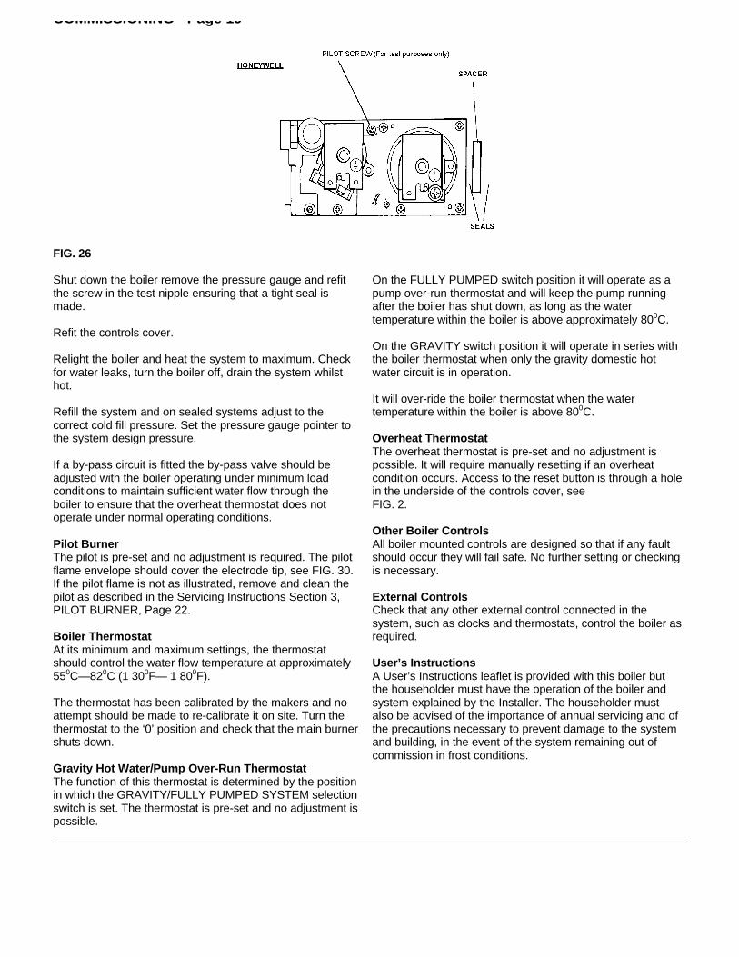
FIG. 26
Shut down the boiler remove the pressure gauge and refitthe screw in the test nipple ensuring that a tight seal ismade.
Refit the controls cover.
Relight the boiler and heat the system to maximum. Checkfor water leaks, turn the boiler off, drain the system whilsthot.
Refill the system and on sealed systems adjust to thecorrect cold fill pressure. Set the pressure gauge pointer tothe system design pressure.
If a by-pass circuit is fitted the by-pass valve should beadjusted with the boiler operating under minimum loadconditions to maintain sufficient water flow through theboiler to ensure that the overheat thermostat does notoperate under normal operating conditions.
Pilot BurnerThe pilot is pre-set and no adjustment is required. The pilotflame envelope should cover the electrode tip, see FIG. 30.If the pilot flame is not as illustrated, remove and clean thepilot as described in the Servicing Instructions Section 3,PILOT BURNER, Page 22.
Boiler ThermostatAt its minimum and maximum settings, the thermostatshould control the water flow temperature at approximately550C—820C (1 300F— 1 800F).
The thermostat has been calibrated by the makers and noattempt should be made to re-calibrate it on site. Turn thethermostat to the ‘0’ position and check that the main burnershuts down.
Gravity Hot Water/Pump Over-Run ThermostatThe function of this thermostat is determined by the positionin which the GRAVITY/FULLY PUMPED SYSTEM selectionswitch is set. The thermostat is pre-set and no adjustment ispossible.
On the FULLY PUMPED switch position it will operate as apump over-run thermostat and will keep the pump runningafter the boiler has shut down, as long as the watertemperature within the boiler is above approximately 800C.
On the GRAVITY switch position it will operate in series withthe boiler thermostat when only the gravity domestic hotwater circuit is in operation.
It will over-ride the boiler thermostat when the watertemperature within the boiler is above 800C.
Overheat ThermostatThe overheat thermostat is pre-set and no adjustment ispossible. It will require manually resetting if an overheatcondition occurs. Access to the reset button is through a holein the underside of the controls cover, seeFIG. 2.
Other Boiler ControlsAll boiler mounted controls are designed so that if any faultshould occur they will fail safe. No further setting or checkingis necessary.
External ControlsCheck that any other external control connected in thesystem, such as clocks and thermostats, control the boiler asrequired.
User’s InstructionsA User’s Instructions leaflet is provided with this boiler butthe householder must have the operation of the boiler andsystem explained by the Installer. The householder mustalso be advised of the importance of annual servicing and ofthe precautions necessary to prevent damage to the systemand building, in the event of the system remaining out ofcommission in frost conditions.
COMMISSIONING - Page 20
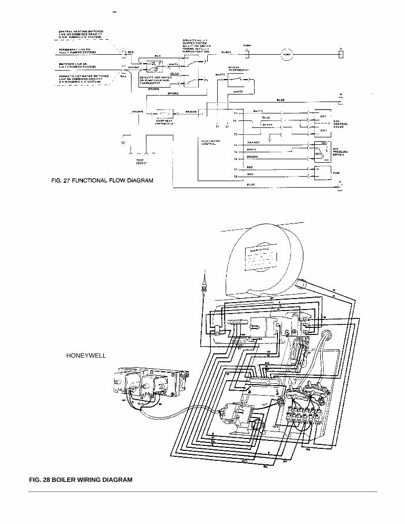
HONEYWELL
FIG. 28 BOILER WIRING DIAGRAM
SERVICING INSTRUCTIONS - Page 21
Regular skilled servicing and cleaning of the appliance isessential to ensure continued safe and efficient operation.The frequency of cleaning will depend upon the particularinstallation conditions, and the use to which the appliance isput, but in general, once per year should be adequate.It is the law that all gas appliances are installed andserviced by competent persons as stated in Gas Safety(Installation and Use) Regulations 1994.
For Health and Safety information see back page.
Electrical installation and servicing should be carried out bya competent person in accordance with the I.E.E. WiringRegulations.
Servicing is best arranged by a contract placed withPotterton Myson Limited and further details are availablefrom our Service Operations Department.
The boiler DATA PLATE and WIRING DIAGRAM areattached to the inside of the controls cover. The boilerCODE NUMBER which should be quoted when orderingspares or requesting information is on the front of thecontrol box. See FIG. 2.
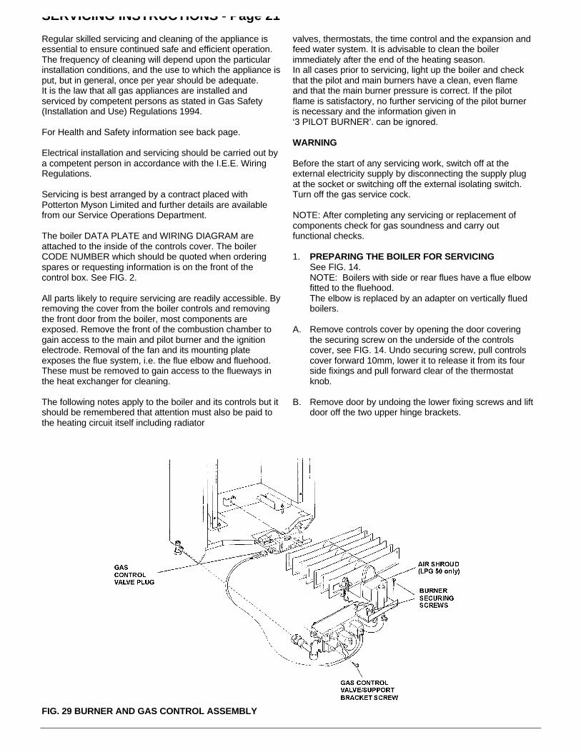
All parts likely to require servicing are readily accessible. Byremoving the cover from the boiler controls and removingthe front door from the boiler, most components areexposed. Remove the front of the combustion chamber togain access to the main and pilot burner and the ignitionelectrode. Removal of the fan and its mounting plateexposes the flue system, i.e. the flue elbow and fluehood.These must be removed to gain access to the flueways inthe heat exchanger for cleaning.
The following notes apply to the boiler and its controls but itshould be remembered that attention must also be paid tothe heating circuit itself including radiator
valves, thermostats, the time control and the expansion andfeed water system. It is advisable to clean the boilerimmediately after the end of the heating season.In all cases prior to servicing, light up the boiler and checkthat the pilot and main burners have a clean, even flameand that the main burner pressure is correct. If the pilotflame is satisfactory, no further servicing of the pilot burneris necessary and the information given in‘3 PILOT BURNER’. can be ignored.
WARNING
Before the start of any servicing work, switch off at theexternal electricity supply by disconnecting the supply plugat the socket or switching off the external isolating switch.Turn off the gas service cock.
NOTE: After completing any servicing or replacement ofcomponents check for gas soundness and carry outfunctional checks.
1. PREPARING THE BOILER FOR SERVICINGSee FIG. 14.NOTE: Boilers with side or rear flues have a flue elbowfitted to the fluehood.The elbow is replaced by an adapter on vertically fluedboilers.
A. Remove controls cover by opening the door coveringthe securing screw on the underside of the controlscover, see FIG. 14. Undo securing screw, pull controlscover forward 10mm, lower it to release it from its fourside fixings and pull forward clear of the thermostatknob.
B. Remove door by undoing the lower fixing screws and liftdoor off the two upper hinge brackets.
FIG. 29 BURNER AND GAS CONTROL ASSEMBLY
SERVICING INSTRUCTIONS - Page 22
C. Remove screws securing the combustion chamber frontpanel and remove panel.
D. Disconnect the fan supply leads from the connec-toradjacent to the fan.
E. Remove the screws securing the fan mounting plateleaving in place the three screws identified with a red circleor adjacent ‘F’ mark in fan plate.Remove mounting plate complete with fan.
F. Disconnect the two flexible tubes from the flue elbow oradapter.
G. Loosen the two brass securing nuts beneath the flue elbowoutlet and remove the other two. Tilt the flange andwithdraw the elbow. Take care not to damage the gasket.On vertically flued boilers remove the four brass nuts andslide the vertical flue adapter up into the flue duct.
NOTE: Do not use a wire brush or pin to clean injector.
D. Gently clean any deposits from the electrode.
E. Refit the pilot injector to the pilot burner and assemble thepilot to the aluminium tube.
F. Secure the pilot assembly to the main burner using twohexagonal screws.
G. Fully tighten the union nut connecting the tube tothe pilot.Check for gas soundness at this joint by following theprocedure described in the commissioning section of theseinstructions, Page 18.
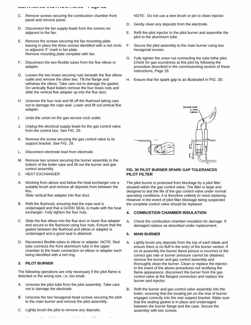
H. Ensure that the spark gap is as illustrated in FIG. 30.
H. Unscrew the four nuts and lift off the fluehood taking carenot to damage the rope seal. Lower and lift out vertical flueadapter.
I. Undo the union on the gas service cock outlet.
J. Unplug the electrical supply leads for the gas control valvefrom the control box. See FIG. 29.
K. Remove the screw securing the gas control valve to itssupport bracket. See FIG. 29.
L. Disconnect electrode lead from electrode.
M. Remove two screws securing the burner assembly to thebottom of the boiler case and lift out the burner and gascontrol assembly. FIG. 30 PILOT BURNER SPARK GAP TOLERANCES
2. HEAT EXCHANGER
A. Working from above and below the heat exchanger use asuitable brush and remove all deposits from between thefins.Slide vertical flue adapter into flue duct.
B. Refit the fluehood, ensuring that the rope seal isundamaged and that a GOOD SEAL is made with the heatexchanger. Fully tighten the four nuts.
C. Slide the flue elbow into the flue duct or lower flue adapterand secure to the fluehood using four nuts. Ensure that thegasket between the fluehood and elbow or adapter isundamaged and a good seal is obtained.
D. Reconnect flexible tubes to elbow or adapter. NOTE: Redtube connects the front aluminium tube in the upperchamber to the lower connection on elbow or adapter eachbeing identified with a red ring.
3. PILOT BURNER
The following operations are only necessary if the pilot flame isdistorted or the wrong size, i.e. too small.
A. Unscrew the pilot tube from the pilot assembly. Take carenot to damage the electrode.
B. Unscrew the two hexagonal head screws securing the pilotto the main burner and remove the pilot assembly.
C. Lightly brush the pilot to remove any deposits.
Unscrew the pilot injector and clean its orifice or replace.
PILOT FILTER
The pilot burner is protected from blockage by a pilot filtersituated within the gas control valve. The filter is large anddesigned to last the life of the gas control valve under normaloperating conditions, it is therefore unlikely to need replacing.However in the event of pilot filter blockage being suspectedthe complete control valve should be replaced.
4. COMBUSTION CHAMBER INSULATION
A. Check the combustion chamber insulation for damage. Ifdamaged replace as described under replacement.
5. MAIN BURNER
A. Lightly brush any deposits from the top of each blade andensure there is no fluff in the entry of the burner venturi. Ifon re-assembly the burner flame picture is incorrect or thecorrect gas rate or burner pressure cannot be obtained,remove the burner and gas control assembly andthoroughly clean the burner. Clean or replace the injector.In the event of the above procedures not rectifying theflame appearance, disconnect the burner from the gascontrol valve at the flanged connection and replace theburner and injector.
B. Refit the burner and gas control valve assembly into theboiler, ensuring that the locating pin on the rear of burnerengages correctly into the rear support bracket. Make surethat the sealing gasket is in place and undamagedbetween the burner flange and the case. Secure theassembly with two screws.

SERVICING INSTRUCTIONS - Page 23
C. Refit the screw securing the gas control valve to the supportbracket.
D. Reconnect electrode lead to electrode.
E. Plug gas control valve supply leads into control box.
F. Reconnect gas supply at gas service cock and turn on gas.
G. Refit the combustion chamber front panel.
6. FAN
A. Carefully clean any deposits from around the fan motor and itssupports.
B. Very gently clean the fan impellor taking care not to damagethe aluminium impellor or dislodge its balance weights.
C. Replace the fan and its mounting plate. Ensure that thesecuring screws are fully tightened as an air tight seal must beobtained between the fan assembly and the main boilercasing.
D. Reconnect the fan supply leads (polarity is not important).
7. CASE SEAL
Check the case door seal. Replace if damaged. The seal issimply pressed into the channel around the door.
8. RECOMMISSION
Follow the full commissioning procedure as detailed in theCOMMISSIONING section of these instructions page 18.
9. OTHER BOILER MOUNTED UNITS
No further servicing is required on any other boiler mountedunits. Repair is by replacement.
10. FAULT FINDING
Refer to Fault Finding Chart FIG. 31 and Wiring DiagramFIGS. 27, 28.
REMOVAL/REPLACEMENT OF BOILER MOUNTED UNITS
GAS CONTROL VALVE
This operation is most easily carried out by first removing theburner and gas control valve assembly as follows:—
1. Switch off the external electricity supply by disconnecting theplug at the socket or switching off the external isolating switch.
2. Remove controls cover, case door and combustion chamberfront panel as described in 1. ‘Preparing the Boiler forServicing’, operations A, B and C.
3. Remove the burner and gas control assembly as described in1. ‘Preparing the Boiler for Servicing’, operations I, J, K, L andM.
4. Disconnect the electrical supply wires from the gas controlvalve noting their position. Refer to FIGS. 27, 28.
5. Unscrew the union connecting the pilot supply pipe to the gascontrol valve.
6. Separate the gas control valve from the flanges at the inletand outlet ports by removing the securing screws.
NOTE: A spacer is used between the valve outlet and the burnerflange, requiring the use of two seals at this point. See FIG. 26.
7. Use new seals on reassembly.
8. Replacement is the reverse of removal.
9. Follow the full commissioning procedure as detailed in theCOMMISSIONING section of these instructions. Page 18.
FAN
1. Switch off the external electricity supply by disconnecting theplug at the socket or switching off the external isolating switch.
2. Remove controls cover and case door as described in 1.‘Preparing the Boiler for Servicing’, operations A and B.
3. Disconnect the fan supply leads from the connnector adjacentto the fan.
4. Remove the screws securing the fan to the mounting plateand remove fan.
5. Replacement is the reverse of removal.
6. Follow the full commissioning procedure as detailed in theCOMMISSIONING section of these instructions. Page 18.
MAIN BURNER
1. Switch off the external electricity supply by disconnecting theplug at the socket or switching off the external isolating switch.
2. Remove controls cover, case door and combustion chamberfront panel as described in 1 ‘Preparing the Boiler forServicing’, operations A, B and C.
3. Remove the burner and gas control assembly as described in1 .‘Preparing the Boiler for Servicing’, operations I, J, K, L andM.
4. Unscrew the union nuts connecting the pilot supply pipe to thepilot and gas control valve. Take care not to damage theelectrode.
Remove sealing grommet and withdraw the pilot tube throughthe hole in the burner mounting flange.
5. Separate the burner from the gas control valve at the flangedconnection by removing the four securing screws.
NOTE: A spacer is used between the valve outlet and theburner flange, requiring the use of two seals at this point. SeeFIG. 26.
6. Unscrew the pilot, main burner injector and pressure testnipple from the burner. On LPG 50e boiler access to the mainbumer injector is improved by first removing the air shroud.See FIG. 29.
7. Use new sealing gaskets on reassembly.
8. Replacement is the reverse of removal. Ensure that the airshroud is refitted on LPG 50e boilers
9. Follow the full commissioning procedure as detailed in theCOMMISSIONING section of these instructions. Page 18.
PILOT/IGNITION ELECTRODE
1. Switch off the external electricity supply by discon-
SERVICING INSTRUCTIONS - Page 24
necting the plug at the socket or switching off the externalisolating switch.
2. Remove controls cover, case door and combustion chamberfront panel as described in 1 .‘Preparing the Boiler forServicing’, operations A, B and C.
3. Disconnect the electrode lead from electrode.
4. Unscrew the pilot tube from the pilot assembly. Take care notto damage the electrode.
5. Unscrew the two hexagonal head screws securing the pilot tothe main burner and remove pilot assembly.Remove the screw securing the electrode and withdrawelectrode.
6. Replacement is the reverse of removal. On reassemblyensure that the spark gap is as illustrated in FIG. 30.
7. Follow the full commissioning procedure as detailed in theCOMMISSIONING section of these instruction. Page 18.
COMBUSTION CHAMBER INSULATION
1. Switch off the external electricity supply by disconnecting theplug at the socket or switching off the external isolating switch.
2. Remove main burner as described in ‘Preparing the Boiler forServicing’, operations A, B, C, I, J, K, L, M.
3. Bend back retaining tabs and replace insulation. It isnecessary to first remove the side insulation when replacingthe rear.
4. Replacement is the reverse of removal.
5. Follow the full commissioning procedure as detailed in theCOMMISSIONING section of these instructions. Page 18.
FUSE, ELECTRONIC CONTROL, PRESSURE SWITCH, BOILERTHERMOSTAT, OVERHEAT THERMOSTAT, GRAVITY HOTWATER/PUMP OVERRUN THERMOSTAT
The following initial operations 1-3 are necessary to remove andreplace any of the above items.
1. Switch off the external electricity supply by disconnecting theplug at the socket or switching off the external isolating switch.
2. Remove controls cover by opening the door covering thesecuring screw on the underside of the controls cover seeFIG. 14. Undo securing screw, pull controls cover forward10mm, lower it to release it from its four side fixings and pullforward clear of the thermostat knob.
3. Remove control box securing screw and lower control box.
FUSE 1 amp
4. The fuse is located on the electronic control and can bereplaced by lifting it from its holder.
5. Replacement is the reverse of removal. Refer to FIGS. 27, 28.
ELECTRONIC CONTROL
4. Disconnect six way plug, two way plug and electrode leadfrom the electronic control. Refer to FIGS. 27, 28.
Disconnect the flying leads of the electronic control asfollows:—
white wire from terminal C(3) of the control thermostat
white wire from terminal NC(2) of the control thermostat
brown wire from overheat thermostat
blue wire from boiler terminal block connection N
green/yellow wire from earth post
5. Release the control by lifting it from the four retaining lugs.
6. Remove electronic control.
7. Replacement is the reverse of removal.
8. Follow the full commissioning procedure as detailed in theCOMMISSIONING section of these instructions. Page 18.
PRESSURE SWITCH
4. Remove the screw securing the pressure switch to the bracketin the control box. Lift pressure switch from bracket.
5. Disconnect the two plastic tubes. NOTE: the red tube isconnected to the pressure switch connection identified with ared ring or adjacent red spot.
6. Disconnect the three electrical leads, white wire from terminalNo. 1, or NC orange from terminal No. 2 or NO and brownfrom terminal No. 3 or C. Refer to FIGS 27, 28.
7. Replacement is the reverse of removal. Ensure that the plastictubes are not kinked on re-assembly.
8. Follow the full commissioning procedure as detailed in theCOMMISSIONING section of these instructions. Page 18.
OVERHEAT THERMOSTAT
4. Remove door by undoing the two lower fixing screws andlifting door off the two upper hinge brackets.
5. Disconnect the two push on electrical connections from theoverheat thermostat terminals.
6. Remove the nut securing the overheat thermostat to itsmounting bracket.
7. Noting the route taken by the capillary, loosen the plasticscrew retaining the thermostat bulb and withdraw bulb from itspocket. Remove the split grommet in the base of the boiler,feed the thermostat capillary and bulb through the hole.
8. Replacement is the reverse of removal. Ensure the rubbergrommet in the base of the boiler makes a good seal aroundthe capillary. Ensure that the capillary is secure in the clipsprovided. Refer to FIG. 21.
9. Follow the full commissioning procedure as detailed in theCOMMISSIONING section of these instructions. Page 18.
BOILER THERMOSTAT
4. Remove door by undoing the two lower fixing screws andlifting door off the two upper hinge brackets.
5. Disconnect the fan supply leads from the connector
SERVICING INSTRUCTIONS - Page 25
adjacent to the fan.6. Remove the screws securing the fan mounting plate, leaving
in place the three screws circled red, and remove the platecomplete with fan.
7. Disconnect the electrical connections as follows:—White from terminal C(3). White from NC(2)Refer to FIGS. 27, 28.
8. Pull off the outer thermostat knob.
9. Remove inner thermostat post by undoing the two securingscrews.
10. Remove the nut securing the thermostat to the control box.
11. If the boiler is fitted with a left hand flue, remove the flue elbowas described in Section 1 Preparing the Boiler operations F,G, page 22.
12. Remove the clip securing the thermostat bulb to the flow pipe.
13. Remove the split grommet in the base of the boiler and thesplit grommet in the fan chamber. Feed the capillary and bulbthrough the holes.
14. Replacement is the reverse of removal. The bulb of the newthermostat should be coated with heat conducting paste.Ensure the rubber grommets in the base of the boiler and thefan chamber make a good seal around the capillary.
15. Ensure that the capillary is secure in the clips provided.
Follow the full commissioning procedure as detailed in theCOMMISSIONING section of these instructions. Page 18.
GRAVITY HOT WATER/PUMP OVER-RUN THERMOSTAT. Referto FIG. 2.
4. Remove door by undoing the lower fixing screws and liftingdoor off the two upper hinge brackets.
5. Disconnect the electrical connections as follows:—
2 red wires from terminal NO(4)
2 brown wires from terminal NC(2)
1 white and 1 blue wire from terminal C(3)
6. Remove the screws securing the thermostat to the controlbox.
7. Remove the split pin retaining the thermostat bulb in thepocket and withdraw the bulb.
8. Remove the split grommet in the base of the boiler. Feed thecapillary and bulb through the hole.
9. Replacement is the reverse of removal. The bulb of the newthermostat should be coated with heat conducting paste.Ensure the rubber grommet makes a good seal around thecapillary.
10. Ensure that the capillary is secure in the clips provided. Followthe full commissioning procedure as detailed in theCOMMISSIONING section of these instructions. Page 18.
Publication No. 559870/029
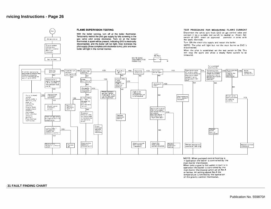
Servicing Instructions - Page 26
FIG 31 FAULT FINDING CHART
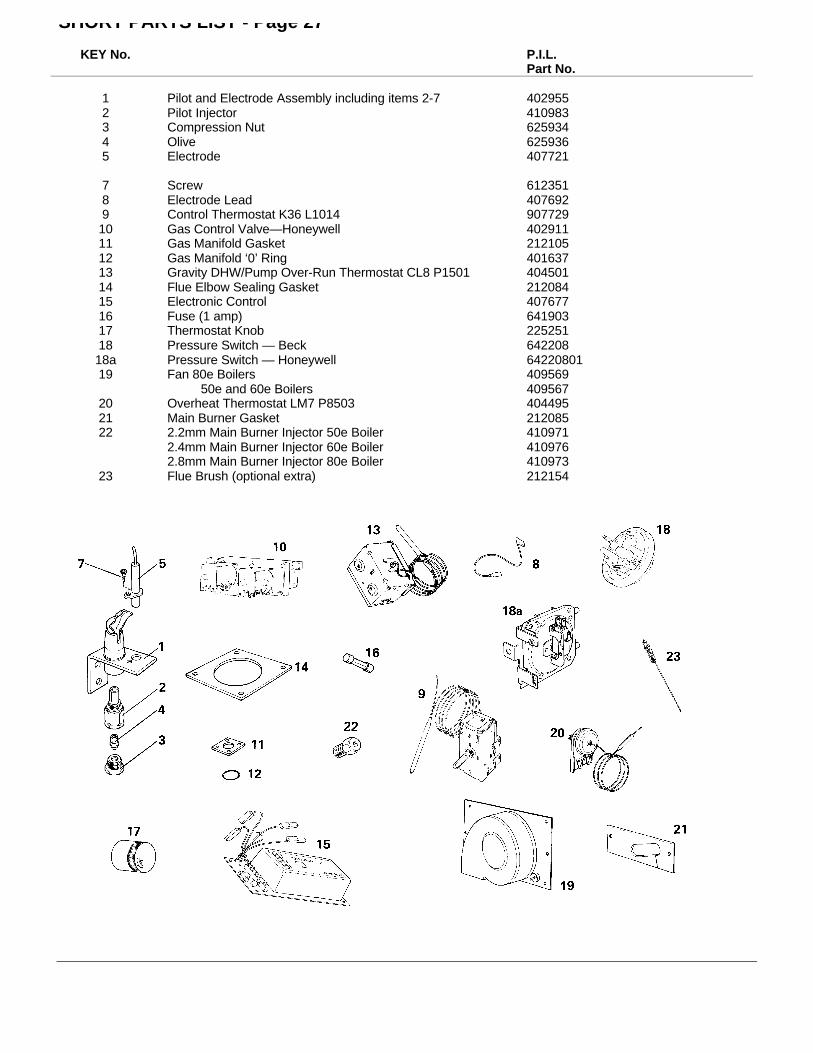
SHORT PARTS LIST - Page 27
KEY No. P.I.L.Part No.
1 Pilot and Electrode Assembly including items 2-7 4029552 Pilot Injector 4109833 Compression Nut 6259344 Olive 6259365 Electrode 407721
7 Screw 6123518 Electrode Lead 4076929 Control Thermostat K36 L1014 90772910 Gas Control Valve—Honeywell 40291111 Gas Manifold Gasket 21210512 Gas Manifold ‘0’ Ring 40163713 Gravity DHW/Pump Over-Run Thermostat CL8 P1501 40450114 Flue Elbow Sealing Gasket 21208415 Electronic Control 40767716 Fuse (1 amp) 64190317 Thermostat Knob 22525118 Pressure Switch — Beck 64220818a Pressure Switch — Honeywell 6422080119 Fan 80e Boilers 409569
50e and 60e Boilers 40956720 Overheat Thermostat LM7 P8503 40449521 Main Burner Gasket 21208522 2.2mm Main Burner Injector 50e Boiler 410971
2.4mm Main Burner Injector 60e Boiler 4109762.8mm Main Burner Injector 80e Boiler 410973
23 Flue Brush (optional extra) 212154
HEALTH AND SAFETY INFORMATION FOR THEINSTALLER AND SERVICE ENGINEER
Under the Consumer Protection Act 1987 and section 6 of the Health and Safety at Work Act1974, we are required to provide information on substances hazardous to health.
Small quantities of adhesives and sealants used in the product are cured and present noknown hazards.
The following substances are also present.
Insulation & SealsMaterial — Ceramic Fibre;
Alumino — Silicone Fibre
Description — Boards, Ropes, Gaskets
Known Hazards — Some people can suffer reddening and itching ofthe skin. Fibre entry into the eye will causeforeign body irritation.Irritation to respiratory tract.
Precautions — People with a history of skin complaints may beparticularly susceptible to irritation.High dust levels are only likely to arise followingharsh abrasion.In general, normal handling and use will notpresent discomfort, follow good hygienepractices, wash hands before consuming food,drinking or using the toilet.
First Aid — Medical attention must be sought following eyecontact or prolonged reddening of the skin.
Thermostat
Material — Contains very small quantity of xylene.
Description — Sealed phial and capillary containing liquid.
Known Hazards — Irritating to skin, eyes and throat.Vapour is harmful.Inflammable — do not extinguish with water.
Precautions — Do not incinerate.Avoid contact with broken/leaking phials.Do not purposely puncture.
First Aid — Eye/skin contact, wash with clean water, seekmedical attention.
Back Page