lower-limb wearable exoskeleton
DESCRIPTION
ExoskeletonTRANSCRIPT
26
Lower-Limb Wearable Exoskeleton
J.L. Pons, J.C. Moreno, F.J. Brunetti, E. Rocon. Bioengineering Group, Instituto de Automática Industrial - CSIC
Spain
1. Introduction
There are numerous causes that can affect the functioning of the human locomotor system, leading to the appearance of joint disorders in the lower limb and generating atypical gait patterns. The importance of research and development in assistance technologies to compensate pathological gait have been recognised since the beginning of the twentieth century and numerous challenges still lie ahead to make their clinical application a reality. In this section, GAIT, the lower-limb Wearable exoskeleton is presented, conceived as a compensation and evaluation system of pathological gait, for application in real conditions as a combined assistance and assessment methodology of the problems affecting mobility in individuals with neuromotor disorders. The main technological challenges are discussed with respect to sensing, actuation and control subsystems. Special emphasis is placed on advances in robotic lower-limb orthoses, and biomechanical requirements, structural design considerations and the approaches existing to develop robust real-time controllers for portable solutions with a common aim, human motor control, are analysed.
2. Normal and pathological human gait
Regarding gait disabilities due to neurological, orthopaedic or traumatic conditions, there are different robotic approaches, and a classification of lower-limb robotic exoskeletons is presented in Rehabilitating robots, evaluation and tracking systems, and functional recovery wearable systems. The cyclical process of events during gait is known as the gait cycle, and it starts and ends the moment when one of the feet come into contact with the ground, and the stance phase begins. While one leg displaces moving the body, the other leg acts as a support; thus, the state of the lower extremity is divided into two phases depending on its situation with regard to the ground: swing phase and stance phase. During gait at normal speeds there is a short period of simultaneous support of both legs. As speed increases a cycle is reached where there are no bipodal supports. Gait can be characterised by a set of parameters: stride length, step length, rhythm and speed. The complexity of the human locomotion process implies studying the cyclical movements that are executed, considering the kinematics and kinetics (forces and moments) and also the work, energy and power engaged in the process. Moreover, to understand all the phenomenon, it is necessary to have knowledge of the principles and neurological movements that control movement, the periphery input or sensory systems that intervene and the mechanisms that command the musculoskeleton system.
Source: Rehabilitation Robotics, Book edited by Sashi S Kommu,ISBN 978-3-902613-04-2, pp.648, August 2007, Itech Education and Publishing, Vienna, Austria
Ope
nA
cces
sD
atab
ase
ww
w.i-
tech
onlin
e.co
m
472 Rehabilitation Robotics
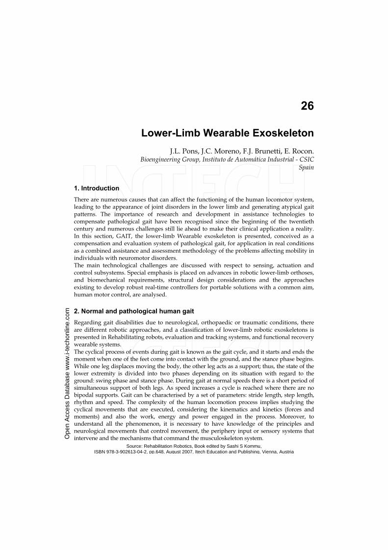
Fig. 1. Normal gait biomechanical data: angles (upper panel), moments (middle panel) and power (lower panel) of the ankle joint (left) and knee joint (right) at natural cadence (105 steps/min).
Typical patterns that characterise the biomechanics of joints obtained from normality
average data (Winter, 1991) are shown in Figure 1. The temporary tracking of these
variables is used to characterise a gait cycle. During rehabilitation therapies it is frequent to
find patients affected at unilateral or bilateral level in the hip, knee and/or ankle joints due
to numerous causes. Apart from serious lesions that lead to paralysis of the limbs in charge
of locomotion, there are also disorders that restrict mobility, such as restriction of flexion
during swing, excessive flexion of the knee and drop foot. These conditions can be treated
with orthoses or active exoskeletons. These alterations occur as a result of different
aetiologies, including muscular neurological disorders, trauma sequelae, spina bifida and
others, and it is cerebrovascular accidents, poliomyelitis and post-poliomyelitis, which have
the most impact, apart from other neurological afflictions like multiple sclerosis and
cerebral palsy.
2.1. Impact
Individuals with proximal weakness in the lower limb can benefit from compensation using
orthoses and functional compensation robotic exoskeletons. It is estimated that in the
European Union the percentage of people who suffer diseases associated with reduced
muscular capacity is between 0.05% and 1% of the total population. In the United States
over 1.5 million people are partially or totally paralysed in their extremities. Many
individuals require assistance technologies, and this demand increases with age. There is a
notable increase in the frequency of paralysis in the lower limb with age (Irby et. al., 2002).
Consequently, mobility in individuals with neuromuscular disorders is one of the aspects
most commonly treated by rehabilitation professionals.
Other causes that require technologically advanced systems for the lower limb are
neurological disorders, post-traumatic sequelae, spina bifida and others. Joint instability can
also be caused by insufficiency of stabilising forces due to ligament or bone disorders. The
population of potential users of lower-limb wearable exoskeletons that permit a more
natural gait are not restricted to muscular insufficiency cases but include different causes
that result in gait disorder.
Lower-Limb Wearable Exoskeleton 473
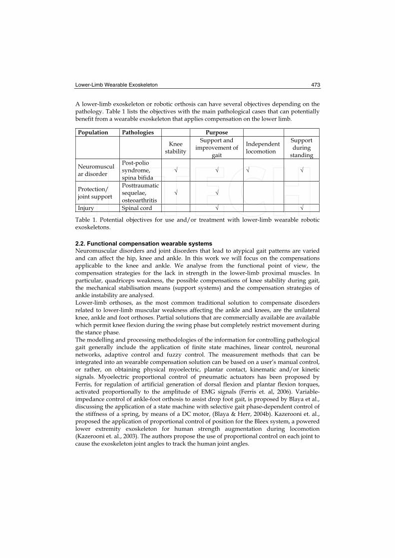
A lower-limb exoskeleton or robotic orthosis can have several objectives depending on the pathology. Table 1 lists the objectives with the main pathological cases that can potentially benefit from a wearable exoskeleton that applies compensation on the lower limb.
Population Pathologies Purpose
Kneestability
Support and improvement of
gait
Independent locomotion
Supportduring
standing
Neuromuscular disorder
Post-poliosyndrome, spina bifida
Protection/joint support
Posttraumaticsequelae, osteoarthritis
Injury Spinal cord
Table 1. Potential objectives for use and/or treatment with lower-limb wearable robotic exoskeletons.
2.2. Functional compensation wearable systems
Neuromuscular disorders and joint disorders that lead to atypical gait patterns are varied and can affect the hip, knee and ankle. In this work we will focus on the compensations applicable to the knee and ankle. We analyse from the functional point of view, the compensation strategies for the lack in strength in the lower-limb proximal muscles. In particular, quadriceps weakness, the possible compensations of knee stability during gait, the mechanical stabilisation means (support systems) and the compensation strategies of ankle instability are analysed. Lower-limb orthoses, as the most common traditional solution to compensate disorders related to lower-limb muscular weakness affecting the ankle and knees, are the unilateral knee, ankle and foot orthoses. Partial solutions that are commercially available are available which permit knee flexion during the swing phase but completely restrict movement during the stance phase. The modelling and processing methodologies of the information for controlling pathological gait generally include the application of finite state machines, linear control, neuronal networks, adaptive control and fuzzy control. The measurement methods that can be integrated into an wearable compensation solution can be based on a user’s manual control, or rather, on obtaining physical myoelectric, plantar contact, kinematic and/or kinetic signals. Myoelectric proportional control of pneumatic actuators has been proposed by Ferris, for regulation of artificial generation of dorsal flexion and plantar flexion torques, activated proportionally to the amplitude of EMG signals (Ferris et. al, 2006). Variable-impedance control of ankle-foot orthosis to assist drop foot gait, is proposed by Blaya et al., discussing the application of a state machine with selective gait phase-dependent control of the stiffness of a spring, by means of a DC motor, (Blaya & Herr, 2004b). Kazerooni et. al., proposed the application of proportional control of position for the Bleex system, a powered lower extremity exoskeleton for human strength augmentation during locomotion (Kazerooni et. al., 2003). The authors propose the use of proportional control on each joint to cause the exoskeleton joint angles to track the human joint angles.
474 Rehabilitation Robotics
Computational methods for modelling and processing of sensory information in locomotion control using neuroprothesis are interesting for their application in lower-limb exoskeletons. Orthoses that do not have joint locking capacity at knee level manage to meet the safety requirements, permit mobility and keep the knee rigid during the full gait extension. However, energy requirements increase unnecessarily and the gait patterns that are obtained are not very natural. There are several types of knee joints and systems commercially available that permit flexion of the knee during the swing phase but restrict movement during the stance phase. The evaluation of these orthoses does not exhibit obvious advantages in terms of energy demand for the patient. The loading application at joint level using an exoskeleton robotic system, which compensates gait disorders, is presented as a promising alternative for patients who cannot benefit from the orthoses available. The main technological challenge to make the application of this type of devices reality consists of a design that considers user aspects, such as portability, aesthetics and ease of use on equal terms. It is concluded that the crucial point is the problems related to the applicability to solutions because of integration problems, problems related to robustness, non-linearity and low repeatability of the sensor systems proposed.
3. The GAIT exoskeleton
Interaction with the human neuromotor system to assist locomotion requires adequate design of the components, both the biomechanical and functional aspects. Robotic exoskeletons conceived as an aid to mobility are designed to be used in numerous environments.The absence of activity in the body segments leads to joint instability and body collapse. To resolve this problem, a robotic exoskeleton should compensate the moment of strength lacking in the joint in order to stabilise and compensate the lack of muscular force. An exoskeleton with an actuation system should appropriately apply the external joint moment on the body segments. The most appropriate force system for knee and ankle joints is analysed below.
3.1. Knee instability compensation
The system should compensate the loss of control of the knee extensors, especially the quadriceps, which put the knee at risk of collapsing under weight. During gait, paralysis of these muscles will tend to have a greater effect just after heel contact. During this period the effect of gravity and the moment of body progression will cause flexion of the knee. Without the quadriceps, the knee would collapse unless stability is maintained with an internal compensation, for example, the use of the hip extensor or trunk flexion during initial stance, or applying an external system. An exoskeleton should ideally have the following actions:
a) Stance phase: controlling the flexion of the knee and assisting the knee to recover total extension.
b) Swing phase: permitting flexion of the knee during swing and assisting extension at the end in preparation for subsequent foot contact.
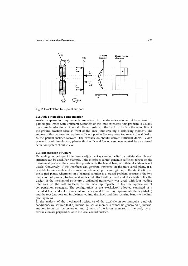
This type of stabilisation can be achieved using a three- or four-force system. For the four-point system (Figure 2), the interface forces will be fewer and also the internal moments on the sagital plane.
Lower-Limb Wearable Exoskeleton 475
Fig. 2. Exoskeleton four-point support.
3.2. Ankle instability compensation
Ankle compensation requirements are related to the strategies adopted at knee level. In pathological cases with unilateral weakness of the knee extensors, this problem is usually overcome by adopting an internally flexed posture of the trunk to displace the action line of the ground reaction force in front of the knee, thus creating a stabilising moment. The success of this manoeuvre requires sufficient plantar flexion power to prevent dorsal flexion as the patient inclines forward. The exoskeleton should deliver sufficient dorsal flexion power to avoid involuntary plantar flexion. Dorsal flexion can be generated by an external actuation system at ankle level.
3.3. Exoskeleton structure
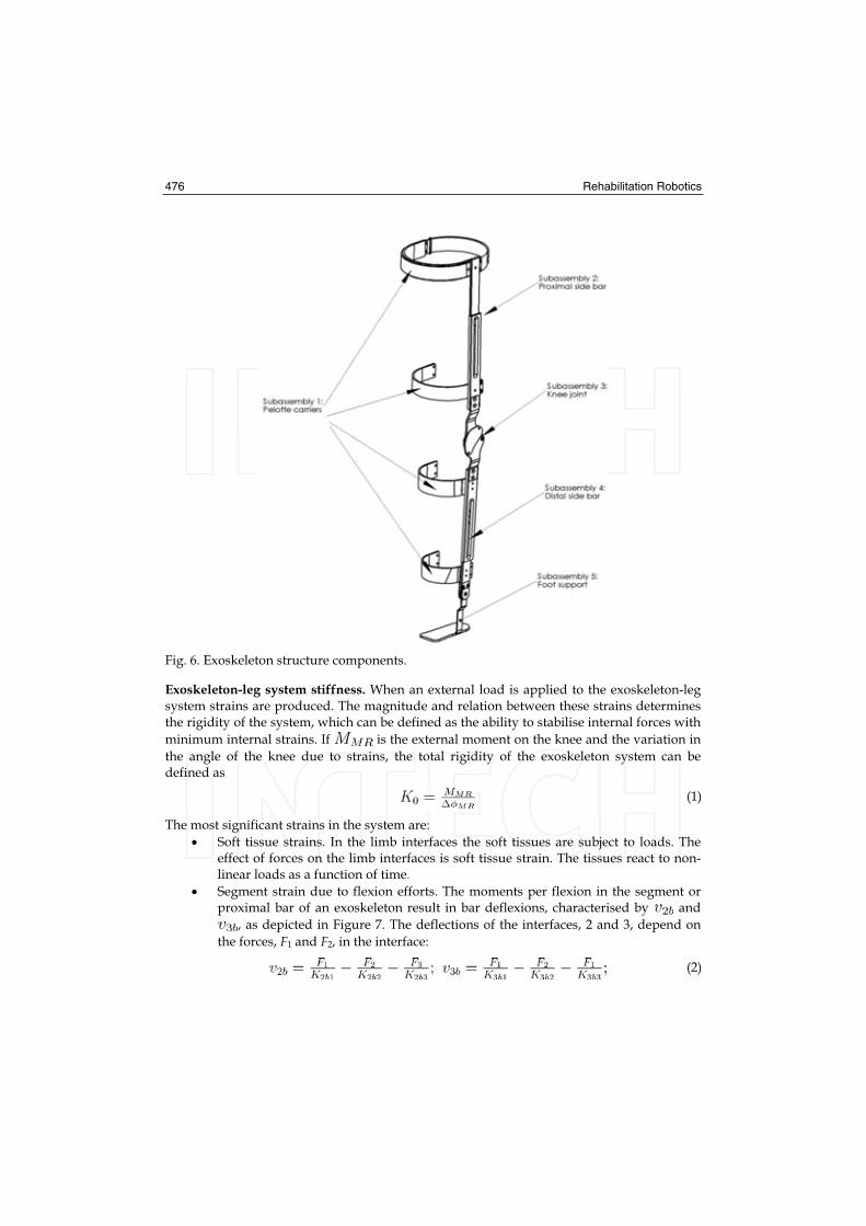
Depending on the type of interface or adjustment system to the limb, a unilateral or bilateral structure can be used. For example, if the interfaces cannot generate sufficient torque on the transversal plane at the connection points with the lateral bars, a unilateral system is not viable. Conversely, if the interfaces can generate moments on the transversal plane, it is possible to use a unilateral exoskeleton, whose supports are rigid to do the stabilisation on the sagital plane. Alignment in a bilateral solution is a crucial problem because if the two joints are not parallel, friction and undesired effort will be produced at each step. For the design of the mechanical structure a unilateral framework was used, with four loading interfaces on the soft surfaces, as the most appropriate to test the application of compensation strategies. The configuration of the exoskeleton adopted consisted of a included knee and ankle joints, lateral bars joined to the thigh (proximal), the leg (distal) and the foot (support and insole inserted into the shoe), and four securing bands to the limb (see Figure 6). In the analysis of the mechanical resistance of the exoskeleton for muscular paralysis conditions, we assume that a) internal muscular moments cannot be generated b) internal support forces can be generated and c) most of the forces exercised in the body by an exoskeleton are perpendicular to the local contact surface.
476 Rehabilitation Robotics
Fig. 6. Exoskeleton structure components.
Exoskeleton-leg system stiffness. When an external load is applied to the exoskeleton-leg system strains are produced. The magnitude and relation between these strains determines the rigidity of the system, which can be defined as the ability to stabilise internal forces with
minimum internal strains. If is the external moment on the knee and the variation in
the angle of the knee due to strains, the total rigidity of the exoskeleton system can be defined as
(1)
The most significant strains in the system are:
Soft tissue strains. In the limb interfaces the soft tissues are subject to loads. The effect of forces on the limb interfaces is soft tissue strain. The tissues react to non-linear loads as a function of time.
Segment strain due to flexion efforts. The moments per flexion in the segment or proximal bar of an exoskeleton result in bar deflexions, characterised by and
, as depicted in Figure 7. The deflections of the interfaces, 2 and 3, depend on
the forces, F1 and F2, in the interface:
(2)
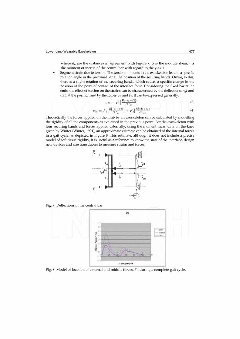
Lower-Limb Wearable Exoskeleton 477
where are the distances in agreement with Figure 7, G is the module shear, J is
the moment of inertia of the central bar with regard to the y-axis.
Segment strain due to torsion. The torsion moments in the exoskeleton lead to a specific rotation angle in the proximal bar at the position of the securing bands. Owing to this, there is a slight rotation of the securing bands, which causes a specific change in the position of the point of contact of the interface force. Considering the fixed bar at the ends, the effect of torsion on the strains can be characterised by the deflections, and
, at the position and by the forces, F1 and F2. It can be expressed generally:
(3)
(4)
Theoretically the forces applied on the limb by an exoskeleton can be calculated by modelling the rigidity of all the components as explained in the previous point. For the exoskeleton with four securing bands and forces applied externally, using the moment mean data on the knee given by Winter (Winter, 1991), an approximate estimate can be obtained of the internal forces in a gait cycle, as depicted in Figure 8. This estimate, although it does not include a precise model of soft tissue rigidity, it is useful as a reference to know the state of the interface, design new devices and size transducers to measure strains and forces.
Fig. 7. Deflections in the central bar.
Fig. 8. Model of location of external and middle forces, F1, during a complete gait cycle.
478 Rehabilitation Robotics
3.4. Knee joint
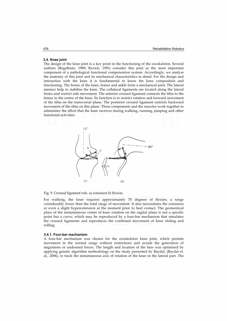
The design of the knee joint is a key point in the functioning of the exoskeleton. Several authors (Regalbuto, 1989; Rovick, 1991) consider this joint as the most important component of a pathological functional compensation system. Accordingly, we analyse the anatomy of this joint and its mechanical characteristics in detail. For the design and interaction with the knee it is fundamental to know the knee composition and functioning. The bones of the knee, femur and ankle form a mechanical joint. The lateral menisci help to stabilise the knee. The collateral ligaments are located along the lateral bones and restrict side movement. The anterior crossed ligament connects the tibia to the femur in the centre of the knee. Its function is to restrict rotation and forward movement of the tibia on the transversal plane. The posterior crossed ligament restricts backward movement of the tibia on this plane. These components and the muscles work together to administer the effort that the knee receives during walking, running, jumping and other functional activities.
Fig. 9. Crossed ligament role. a) extension b) flexion.
For walking, the knee requires approximately 70 degrees of flexion, a range considerably lower than the total range of movement. It also necessitates the extension or even a slight hyperextension at the moment prior to heel contact. The geometrical place of the instantaneous centre of knee rotation on the sagital plane is not a specific point but a curve, which may be reproduced by a four-bar mechanism that simulates the crossed ligaments and reproduces the combined movement of knee sliding and rolling.
3.4.1. Four-bar mechanism
A four-bar mechanism was chosen for the exoskeleton knee joint, which permits movement in the normal range without restrictions and avoids the generation of migrations or undesired forces. The length and location of the bars was optimised by applying genetic algorithm methodology on the study presented by Baydal, (Baydal et. al., 2006), to track the instantaneous axis of rotation of the knee in the lateral part. The
Lower-Limb Wearable Exoskeleton 479
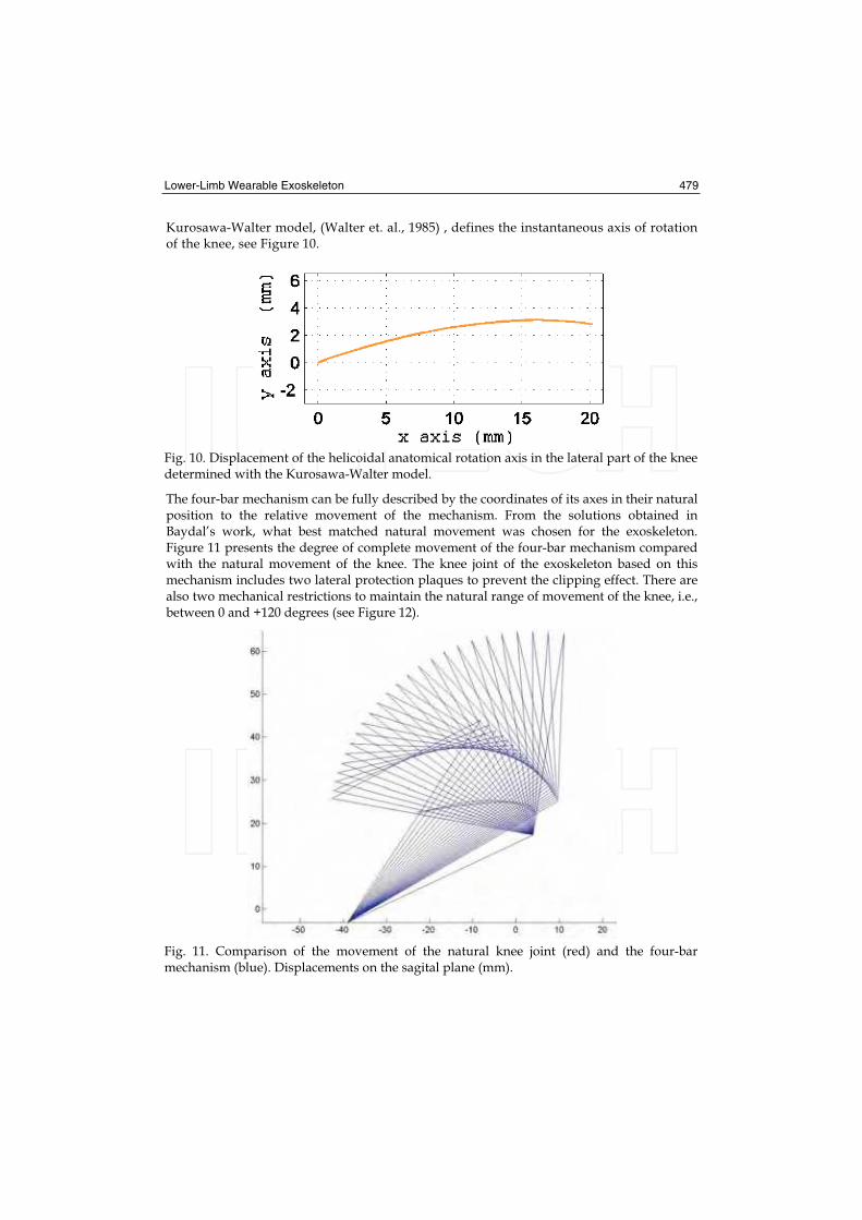
Kurosawa-Walter model, (Walter et. al., 1985) , defines the instantaneous axis of rotation of the knee, see Figure 10.
Fig. 10. Displacement of the helicoidal anatomical rotation axis in the lateral part of the knee determined with the Kurosawa-Walter model.
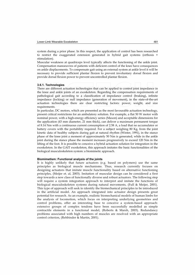
The four-bar mechanism can be fully described by the coordinates of its axes in their natural position to the relative movement of the mechanism. From the solutions obtained in Baydal’s work, what best matched natural movement was chosen for the exoskeleton. Figure 11 presents the degree of complete movement of the four-bar mechanism compared with the natural movement of the knee. The knee joint of the exoskeleton based on this mechanism includes two lateral protection plaques to prevent the clipping effect. There are also two mechanical restrictions to maintain the natural range of movement of the knee, i.e., between 0 and +120 degrees (see Figure 12).
Fig. 11. Comparison of the movement of the natural knee joint (red) and the four-bar mechanism (blue). Displacements on the sagital plane (mm).

480 Rehabilitation Robotics
Fig. 12. Knee joint design.
3.5. Ankle joint
The ankle joint plays an important role in the progression and absorption of impact in the gait-stance phase, and helps to clear the ground during stance. In the complete gait cycle, the ankle does two plantar flexion trajectories and two dorsal flexion trajectories alternately. The design considers a monocentric joint adapted to the anatomy. The joint, whose design considers the trajectory of an external actuator element, varies in size depending on the user’s anthropometric data. In the GAIT exoskeleton the ankle joint is joined to an insole inside the user’s shoe. The shape of the insole follows the curvature of the sole of the foot to achieve effective distribution of the forces and obtain a good support and permit the most natural gait possible. The insole of the exoskeleton was designed with carbon fibre to provide sufficient rigidity to transmit ankle actuator torque and also be an elastic element capable of recovering energy to assist the lifting of the foot from the ground.
3.6. Actuation methodologies
Using an external joint system constant or variable impedance can be obtained. By applying joint locking, i.e., infinite impedance, during gait with quadriceps deficiency, the locomotion capacity can be enabled with joint rigidity. By applying null impedance, with the generation of movement, theoretically it is possible to compensate the absence of torque necessary to generate the joint trajectories. We analyse the functional situation at joint level to the absence of muscular control. The role of the knee extensors, active in the phase prior to stance and the end of the swing phase, is to control the degree of knee flexion which is generated by the ground reaction force. With quadriceps weakness during stance, flexion is uncontrolled and there is the risk of falling. The torque amount necessary will be determined basically by the subject’s weight and his/her remaining muscular capacity. Control of joint impedance during the stance phase is a critical aspect of safety which must guarantee stability for stance and flexion flexibility at the right moment in the phase prior to the swing phase. Moreover, assisting leg extension at the end of the swing phase is a requirement for gait with quadriceps deficiency, because it makes subjects adopt undesired compensatory movements to be able to walk. It is possible to provide torque during the final phase to assist extension using an external system or the recovery of energy of the
Lower-Limb Wearable Exoskeleton 481
system during a prior phase. In this respect, the application of control has been researched to restrict the exaggerated extension generated in hybrid gait systems (orthosis + stimulation). Muscular weakness at quadriceps level typically affects the functioning of the ankle joint. Compensation manoeuvres of patients with deficient control of the knee have consequences on ankle displacements. To compensate gait using an external system at ankle level it will be necessary to provide sufficient plantar flexion to prevent involuntary dorsal flexion and provide dorsal flexion power to prevent uncontrolled plantar flexion.
3.6.1. Technologies
There are different actuation technologies that can be applied to control joint impedance in the knee and ankle joints of an exoskeleton. Regarding the compensation requirements of pathological gait according to a classification of impedance control (braking), infinite impedance (locking) or null impedance (generation of movement), in the state-of-the-art actuation technologies there are clear restricting factors: power, weight, and size requirements.
In particular, DC motors, which are presented as the most favourable actuation technology, present critical restrictions for an ambulatory solution. For example, a flat 50 W motor with nominal power, with a high-energy efficiency series (Maxon) and acceptable dimensions for the application (43 mm diameter, 21 mm thick), can deliver a maximum permanent torque of 8.14 Nm with a continuous current consumption of 2.58 A, a load that no accumulator or battery covers with the portability required. For a subject weighing 80 Kg, from the joint kinetic data of healthy subjects during gait at natural rhythm (Winter, 1991), in the stance phase of the knee joint a moment of approximately 50 Nm is generated, while in the ankle joint during the stance phase the moment increases progressively to exceed 120 Nm in the lifting of the foot. It is possible to conceive a hybrid actuation solution for integration in the exoskeleton. In the GAIT exoskeleton, this approach imitates the basic functionalities of the biological musculoskeleton system: a biomimetic approach.
Biomimetism: Functional analysis of the joints
It is highly unlikely that future actuators (e.g. based on polymers) use the same principles as biological muscle mechanisms. Thus, research currently focuses on designing actuators that imitate muscle functionality based on alternative functioning principles, (Meijer et. al, 2003). Imitation of muscular design can be considered a first step towards a new class of functionally diverse and robust actuators. The following step will require a system integration approach to interpret and imitate the functions of biological musculoskeleton systems during natural movements, (Full & Meijer, 2001). This type of approach will seek to identify the biomechanical principles to be introduced in the artificial model. An approach integrated into actuator design presents great potential for research. As an example, realistic biomechanical models of human limbs for the analysis of locomotion, which focus on interpreting underlying geometries and control problems, offer an interesting base to conceive a system-based approach: extensive groups of complex tendons have been successfully modelled as simple contractile elements in a functional model, (Roberts & Marsh, 2003). Redundancy problems associated with high numbers of muscles are resolved with an appropriate control criterion, (Rehbinder & Martin, 2001).

482 Rehabilitation Robotics
A biomimetic actuator for the compensation of pathological gait should be versatile and adaptable. The crucial construction needs for this system —and any other type of biomimetic wearable device— are low volume and size, low-energy consumption, low-heat dissipation and a high torque (in natural gait, 3.3 W are required per kilogram of body weight during the initial swing phase); we propose a biomimetic design to achieve these requirements. The weakened musculoskeleton system, in the absence of the quadriceps muscular group, requires assistance for impedance control and power generation (maximum demand during gait, 3.3 w/kg) and other compensations already mentioned (foot dragging, difficulty in lifting toe, etc.) We start from the hypothesis that this type of biomimetic system may increase the functionality level by increasing the integration level of actuation and control systems. In order to model and analyse the dynamic behaviour of the two joints during a gait cycle, we propose their separation into functional ranges where mechanical behaviour or impedance can be identified by each joint. We identify the mechanical functioning by analysing the relations between the rotations and joint moments, extracted from mean data representative of net moments and angles, at natural and low rhythms.
Knee
In the knee (see Figure 13), we can identify three functional ranges. The AB range, while the joint during stance is absorbing the impact and damping the descent of the body, the joint set can be modelled as a linear system since the torque-angle relation represents an elastic behaviour given by
(5)
where is the torque, the angular position, 0 the initial state, and the elastic constant
representing the torque-angle rate that varies depending on the subject’s weight and gait speed. The BC range, with flexion and extension trajectories in the swing phase, presents a non-linear relation that can be interpreted as a pseudo-elastic system. This is characterised by an increase in considerable strain with minimum effort applied, once an initial loading effort has been overcome. The CD range, during extension before heel contact, can be characterised mechanically as an elastic system using the K2 elastic constant.
Ankle
In the ankle we identify three ranges (see Figure 14). The first, included between heel contact and a point around maximum flexion, where the joint controls plantar flexion, can be modelled as a linear system because of an elastic relation, which we call K3. During the AB range, dorsal flexion takes place during stance while a T1 absorption zone of energy is observed, and a linear model approximated by a K4 constant elastic can be defined. For the BC range, the plantar flexion trajectory coincides with the maximum energy demand and another approximately linear relation K5 is found, to approach the joint function.
Identification
It can be concluded that joint behaviour can be imitated using elastic devices during certain gait phases. For each functional range, from the data representative of gait normality at natural rhythm, we calculate the coefficients of a first-degree polynomial (A) to linearly adjust p (A(n)) to M(n), using the square-minimum method, where A is the angle of the knee, M the moment of force, n the percentage of the gait cycle.

Lower-Limb Wearable Exoskeleton 483
Fig. 13. Torque-angle rate in the knee joint during a complete gait cycle and identification of functional ranges at natural rhythm (Winter’s average gait data).
Fig. 14. Torque-angle rate in the ankle joint during a complete gait cycle and identification of functional ranges at natural rhythm (Winter’s average gait data).
Range Coefficients (N.m/Kg)
A-B K1 6.013 x10⁻²
C-D K2 4,26 x 10⁻⁵
0-a K3 1,4 x 10⁻⁴
a-b K4 8,9 x 10⁻⁴
b-c K5 7,4 x 10⁻⁴
Table 2. Moment polynomial adjustment coefficients vs. angles calculated for the functional ranges in a gait cycle.

484 Rehabilitation Robotics
Table 2 presents the values of the coefficients obtained for each linear adjustment, depending on body weight. Proceeding in this way we characterise the functional ranges identified using linear parameters. Based on the biomimetic model of the compensation elements of the actuators, the different operation ranges of the musculoskeleton system are identified functionally and they are modelled using mechanisms. Figure 16 represents the
resulting linear adjustments obtained from linear functions with and parameters
which are calculated theoretically for the knee joint. Figure 15 represents the linear approximations for the moment and angle for the ankle joint. The dotted lines represent the phases when an adjustment to a greater order polynomial would be necessary.
Interaction with the four-bar mechanism: viability analysis
The instantaneous centre of rotation (ICR) in the knee joint must be followed by the rotation centre of the four-bar mechanism joint. The mechanism kinematics is crucial for the functioning but this adaptation leads to more complex kinematics and for this reason we analyse the viability of applying external torques on the four-bar mechanism. In the four-bar mechanism, a rotational actuator should transmit or receive torque on the fixed A- or D-axes (see Figure 18). To evaluate the torque relation to the angle on these application points, we developed a model based on the optimised four-bar joint.
Fig. 15. Linear adjustments (blue solid lines) of the angle and force moment for the knee joint and normality patterns (red).
We generate a free-body diagram of the mechanism depicted in Figure 17. To model the knee joint, we consider the optimised values of limb length and we assume that M torque is applied on the ICR. We formulate a linear system of nine equations with nine variables corresponding to the reaction forces to calculate the torque in A for a gait pattern:
Lower-Limb Wearable Exoskeleton 485
(6)
where Ai are the coefficients that define the moments caused by the reaction forces at the application point. The model output evaluated on D-axis, for a complete cycle, is represented in torque terms and angular displacements in Figure 18. In the period between
the load response and the final gait stance phase, the resulting torque on the D-axis,
maintains a linear relation with the axis rotation.
Fig. 16. Linear adjustments (blue solid lines) of the angle and moment of force for the ankle joint and normality patterns (red).
Fig. 17. Diagram of the free-body mechanism.
486 Rehabilitation Robotics
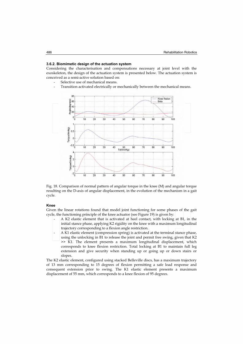
3.6.2. Biomimetic design of the actuation system
Considering the characterisation and compensations necessary at joint level with the exoskeleton, the design of the actuation system is presented below. The actuation system is conceived as a semi-active solution based on:
- Selective use of mechanical means. - Transition activated electrically or mechanically between the mechanical means.
Fig. 18. Comparison of normal pattern of angular torque in the knee (M) and angular torque resulting on the D-axis of angular displacement, in the evolution of the mechanism in a gait cycle.
Knee
Given the linear rotations found that model joint functioning for some phases of the gait cycle, the functioning principle of the knee actuator (see Figure 19) is given by:
- A K2 elastic element that is activated at heel contact, with locking at B1, in the initial stance phase, applying K2 rigidity on the knee with a maximum longitudinal trajectory corresponding to a flexion angle restriction.
- A K1 elastic element (compression spring) is activated at the terminal stance phase, using the unlocking in B1 to release the joint and permit free swing, given that K2 >> K1. The element presents a maximum longitudinal displacement, which corresponds to knee flexion restriction. Total locking at B1 to maintain full leg extension and give security when standing up or going up or down stairs or slopes.
The K2 elastic element, configured using stacked Belleville discs, has a maximum trajectory of 13 mm corresponding to 15 degrees of flexion permitting a safe load response and consequent extension prior to swing. The K1 elastic element presents a maximum displacement of 55 mm, which corresponds to a knee flexion of 95 degrees.
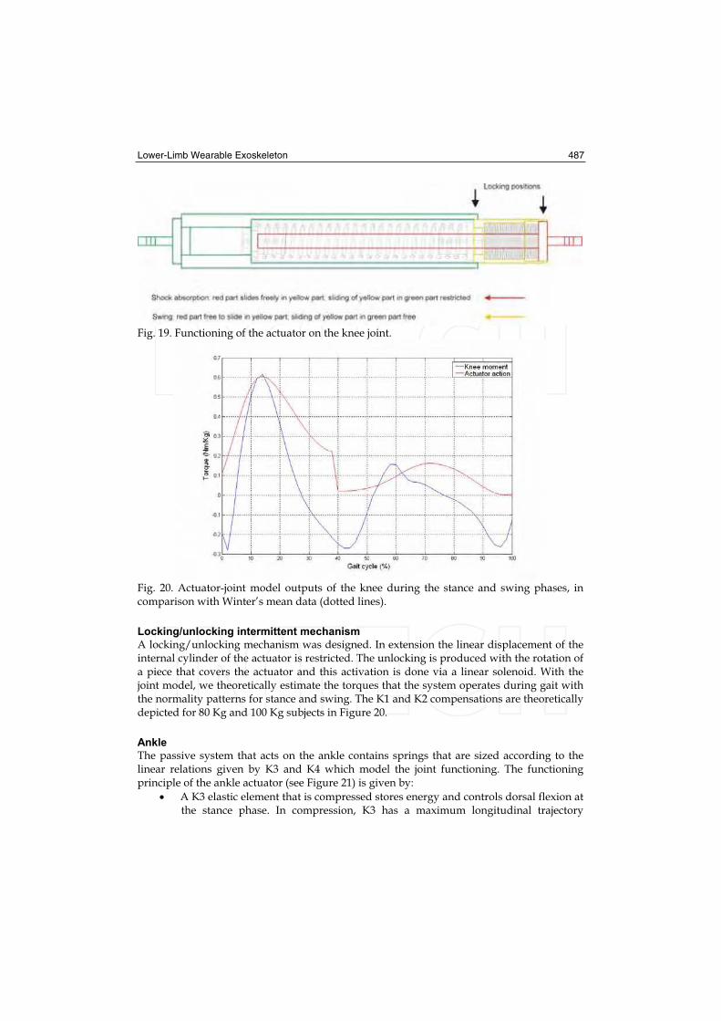
Lower-Limb Wearable Exoskeleton 487
Fig. 19. Functioning of the actuator on the knee joint.
Fig. 20. Actuator-joint model outputs of the knee during the stance and swing phases, in comparison with Winter’s mean data (dotted lines).
Locking/unlocking intermittent mechanism
A locking/unlocking mechanism was designed. In extension the linear displacement of the internal cylinder of the actuator is restricted. The unlocking is produced with the rotation of a piece that covers the actuator and this activation is done via a linear solenoid. With the joint model, we theoretically estimate the torques that the system operates during gait with the normality patterns for stance and swing. The K1 and K2 compensations are theoretically depicted for 80 Kg and 100 Kg subjects in Figure 20.
Ankle
The passive system that acts on the ankle contains springs that are sized according to the linear relations given by K3 and K4 which model the joint functioning. The functioning principle of the ankle actuator (see Figure 21) is given by:
A K3 elastic element that is compressed stores energy and controls dorsal flexion at the stance phase. In compression, K3 has a maximum longitudinal trajectory

488 Rehabilitation Robotics
equivalent to a dorsal flexion restriction of the ankle. The energy stored in dorsal flexion is recovered towards a plantar flexion trajectory prior to swing with the K3 extension.
A K4 elastic element that adds rigidity to extension to control plantar flexion on stance and avoid the drop of the foot during swing. The element has a maximum longitudinal trajectory equivalent to a plantar flexion restriction of the ankle equivalent to a dorsal flexion restriction of the ankle. The energy stored in dorsal flexion is recovered towards a plantar flexion trajectory prior to swing with the K3 extension.
A K4 elastic element that adds rigidity to the extension to control plantar flexion on stance and avoid the drop of the foot during the swing. The element has a maximum longitudinal trajectory equivalent to a plantar flexion restriction of the ankle.
Fig. 21. Functioning of the actuator on the ankle joint.
Fig. 22. Knee (left) and ankle (right) actuators attached to the frame.
In particular, for the design of the knee actuator integrated into the ankle joint, the K3 elastic element (stacked Belleville disc) is compressed with a trajectory of 15 mm equivalent to 20 degrees of dorsal flexion of the ankle. The K4 elastic compression element has a maximum displacement in plantar flexion of 6.5 mm, equivalent to 15 degrees. The final design of the biarticular actuation system integrated into the complete structure of the exoskeleton is presented in Figure 22.

Lower-Limb Wearable Exoskeleton 489
3.7. Sensor system
In previous works, the feasibility of inertial sensing for the control of walking was studied, (Baten et. al., 2004), and a particular design was proposed (Moreno et. al., 2006b). The sensors set up for control consist of an initial inertial measurement unit (IMU) on the foot element inside the shoe (below the orthotic ankle joint) and a second unit for the lower bar of the exoskeleton. Each IMU is composed of a) a single miniature MEMs rate gyroscope, sensing Coriolis force during angular rate by measuring capacitance (Analogue Device ADXRS300, volume less 0.15 cc, weight 0.5 gram) with maximum sensitivity +/- 300/s; and b) a complete dual-axis (surface micromachined) 200mV/g accelerometer (ADXL202 5x4.5x1.78 mm). Units are housed in boxes attached to foot and shank orthotic bars, (as depicted in Figure 23), sensing rotational motion, tilt, tangential and radial segment accelerations in orthogonal directions (X and Y), while the majority of orthotic rotations at the level of joints and bars take place on the locomotion progression plane (sagittal), due to mechanical constraints imposed by the structure. Movements of interest occur at normal (2.6 km/h) and low (2 km/h) gait speeds, and therefore, signals outside the band frequency related to gait kinematics (0.3–20 Hz) are rejected from the sensor outputs with -3 dB low-pass filters, while lowering noise floor by bandwidth restricting. A precision angular position sensor, with an effective electric range of 340 degrees is fixed at one rotation axis of the four-bar mechanism of the knee joint, for continuous tracking of the knee joint angle on the sagittal plane. A resistive pressure sensor (5 mm in diameter active area, 0.30 mm thickness) is used to monitor the knee locking mechanism status. Each IMU is housed in boxes with straight angles and standards, useful for the assembly and development of calibration protocols. Moreover, the robustness of electric connections is another important factor due to the fact that each device will be subject to a high number of flexions, movements, impacts and efforts. The unit on the ankle bar measures rotational movements, inclination and tangential and radial accelerations of the limb in orthogonal direction on the sagittal plane. The same rotations and movements are measured in the leg by the second unit, mounted on the lateral side of the bar. A IMU is on the foot bar that is introduced into the subject’s shoe (under the ankle joint); a second IMU is on the foot bar (on the ankle joint). Figure 23 depicts the locations. The IMU signals are digitalised using a 10-bit analogical-digital converter, sampled at 100 Hz, with a reference voltage of 3.3 V and a resolution of 2.92 mV/bit. Robust fixation and solid movement are assumed. The output of an accelerometer with its measurement axis aligned on the i-axis can be represented by
(7)
being the sensor linear acceleration, , the gravity, and , white noise. Additionally,
from the combination of signals of the accelerometers mounted tangentially, a measurement of the angular acceleration of the limb can be obtained. Using the Coriolis force, , the
gyroscope directly measures the angular speed s(t), which can be represented by the relation
(8)
where m is the sensor mass and s(t) its speed. Thus, the sensor output corresponds to its rotation rate. In a later step and during cyclical gait, the orientation angle of the sensor can be calculated from the signal integration, in periods between consecutive steps, reinitiating the process to eliminate the cumulative error. Integration unbalance can be calculated during the quasi-static conditions detected (e.g. the foot segment during the stance phase, speed equal to zero). The relative angular speed of ankle joint rotation can be calculated from the subtraction between the foot and leg speeds.

490 Rehabilitation Robotics
Fig. 23. Configuration of the IMUs in the structure.
3.8. Gait controller
The strategies that can be applied to functionally compensate pathological gait can be classified according to their implementation a) position control b) impedance control and c) intermittent joint control. We propose selective control of joint rigidity by modifying the joint rigidity of the exoskeleton with exchanged external means. The control strategies implemented in ambulatory means have to be highly robust and should guarantee safe interaction between the human being and the machine. This section discusses the implementation of a strategy based on intermittent joint control.
3.8.1. Functional compensation using intermittent control
All the aspects related to the design and application of intermittent control for functional compensation of gait with the exoskeleton developed are analysed. We consider the lower-limb system consisting of the thigh, leg and foot segments. Weakened quadriceps will provide minimum or null torque amount in the knee. The system is designed to apply torque on the sagittal plane and is restricted by the construction of exoskeleton joints. In the exoskeleton the ankle actuator is designed to passively compensate, i.e., without any need for a control action, and the elastic components (K3 and K4) of the device are customised to match the user’s weight. The spring with K3 is compressed to store energy during the stance phase and control dorsal flexion during the swing phase, and the spring with K4 applies rigidity to control the drop of the foot during the swing phase. The functional objectives of a gait cycle in the exoskeleton-limb system using the actuator control of the knee consist of approximating the characteristic conditions of natural human gait (Figure 24). The compensations using the ankle actuator affect foot movement with consequences on the configuration of all the kinematic chain of the limb and its state in relation to the ground. At knee level, the actuator reacts and generates the transition between the K1 and K2 compensations and passes from knee with restricted flexion to free flexion where the elastic element is loaded that recovers energy to assist the extension. The appropriate transition moment between the actuator components occurs in the phase prior
Lower-Limb Wearable Exoskeleton 491
to swing and coincides with a specific dorsal flexion of the ankle and a period when the direction of rotation of the leg changes to the knee forward movement direction.
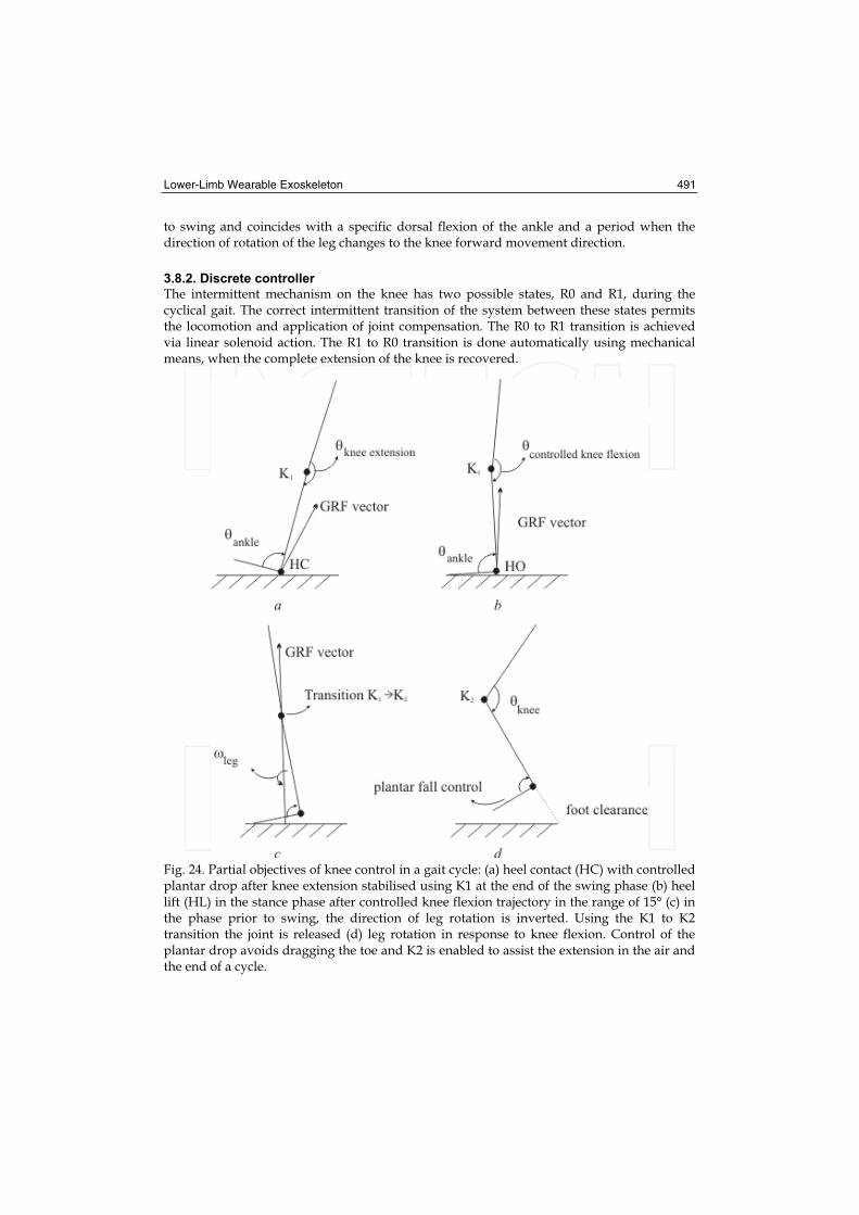
3.8.2. Discrete controller
The intermittent mechanism on the knee has two possible states, R0 and R1, during the cyclical gait. The correct intermittent transition of the system between these states permits the locomotion and application of joint compensation. The R0 to R1 transition is achieved via linear solenoid action. The R1 to R0 transition is done automatically using mechanical means, when the complete extension of the knee is recovered.
Fig. 24. Partial objectives of knee control in a gait cycle: (a) heel contact (HC) with controlled plantar drop after knee extension stabilised using K1 at the end of the swing phase (b) heel lift (HL) in the stance phase after controlled knee flexion trajectory in the range of 15° (c) in the phase prior to swing, the direction of leg rotation is inverted. Using the K1 to K2 transition the joint is released (d) leg rotation in response to knee flexion. Control of the plantar drop avoids dragging the toe and K2 is enabled to assist the extension in the air and the end of a cycle.

492 Rehabilitation Robotics
The aim of the discrete controller is to detect the transition moment (TI) using real time evaluation, at a sampling frequency of 100 Hz, of the information obtained from the inertial measurement units (IMUs) of the exoskeleton. The inertial system embarked directly measures on the sagittal plane, the angular speed of the leg, , the angular speed of
the foot, , and the linear acceleration of the foot limb, , on the y-axis, where y is
parallel to the upper-lower axis of the exoskeleton foot bar. The condition for detecting TI is defined in the cyclical gait discrete controller based on the speed of the segments using the following equation:
(9)
with the and thresholds. The algorithm verifies the rotation of the foot
segment by dorsal flexion of the ankle in the margins given by and , and in turn
verifies the trajectory of the lifting of the foot from the ground using the threshold.
Additionally, the algorithm evaluates the state of the system and degree of flexion of the knee in the swing phase to ensure that no undesired activations of the solenoid occur at the final swing phase.
3.8.3. Activation
The TI detector output in each cycle is a square pulse with a variable width, and a time-rise edge T after TI. This pulse produces activation and displacement of the linear actuator that causes the transition to R1 in the intermittent mechanism.
Fig. 25. GAIT exoskeleton control system.
Ideally, the width of the pulse should be sufficient to ensure that the knee is free the time necessary to initiate the flexion and maximum of half of the magnitude of the swing period. We define as an activation criterion in the gait cycle , the function:
(10)
which evaluates the activation state of the previous cycle, the stance phase of the current
cycle and the two stance phases immediately before, in order to adjust the
activation period of the actuator to match the gait rhythm trend. A is defined a
priori, which should correspond to the mean activation period adjusted to a mean rhythm expected.
Lower-Limb Wearable Exoskeleton 493
3.8.4. Preliminary results
A version of the GAIT exoskeleton operated mechanically has been developed. This mechanical solution is cable-driven exoskeleton (CDE) that switches the state of the knee joint, based on the degree of ankle dorsal flexion. The first results with the (CDE) produces response errors on 2.4% of occasions in technical validation trials of 100 steps. Comparatively, according to the trial data with a normal subject, the controller significantly reduces the rate of errors and obtains 99% success in the functioning of all the trials at low and medium rhythm.
4. Experimental trials
A left-leg unilateral exoskeleton was customised to two patients with post-polio syndrome. The construction of the joints restricted movement at the sagital plane. Special attention was paid to achieving the right mechanical adjustment and adaptation of the exoskeleton to guarantee comfort and the appropriate transmission of forces, with the continual assistance of an expert in orthopaedics. The securing pieces were strained and material was added to adjust to the anatomical form until no marks were left on the skin after using the system for twenty-minute periods. The height of the ankle and toe were adjusted using additional material on the shoe insole, when it was necessary. Each protoype was made with the actuators consisting of the springs built to offer the compensations calculated according to the moment polynomial adjustment coefficients against angle, depending on the subject’s weight (according to the results in Table 2). For the intermittent mechanism of the knee actuator a traction solenoid was anchored (12 Vdc, 10 W, Belling Lee) which transmits the force necessary (up to 700 g, 3 mm trajectory) for the switching between springs and joint unlocking during the stance phase. The solenoid was fed electrically from a lead-sealed battery (Serie Dryfit 1.2Ah, 12V, Sonnenschein) and controlled digitally using a switching circuit in pulsated mode to reduce power consumption. The circuit implements the discharge via a capacitor to offer rapid unlocking. The exoskeletons were made with the set of sensors consisting of the inertial measurement units, the angular position sensor and the resistive pressure sensor (active area of 5 mm and 0.30 mm of thickness) on the unlocking mechanism to detect the state of the knee joint (R0: locking in extension [K1]; R1: free swing [K2]).
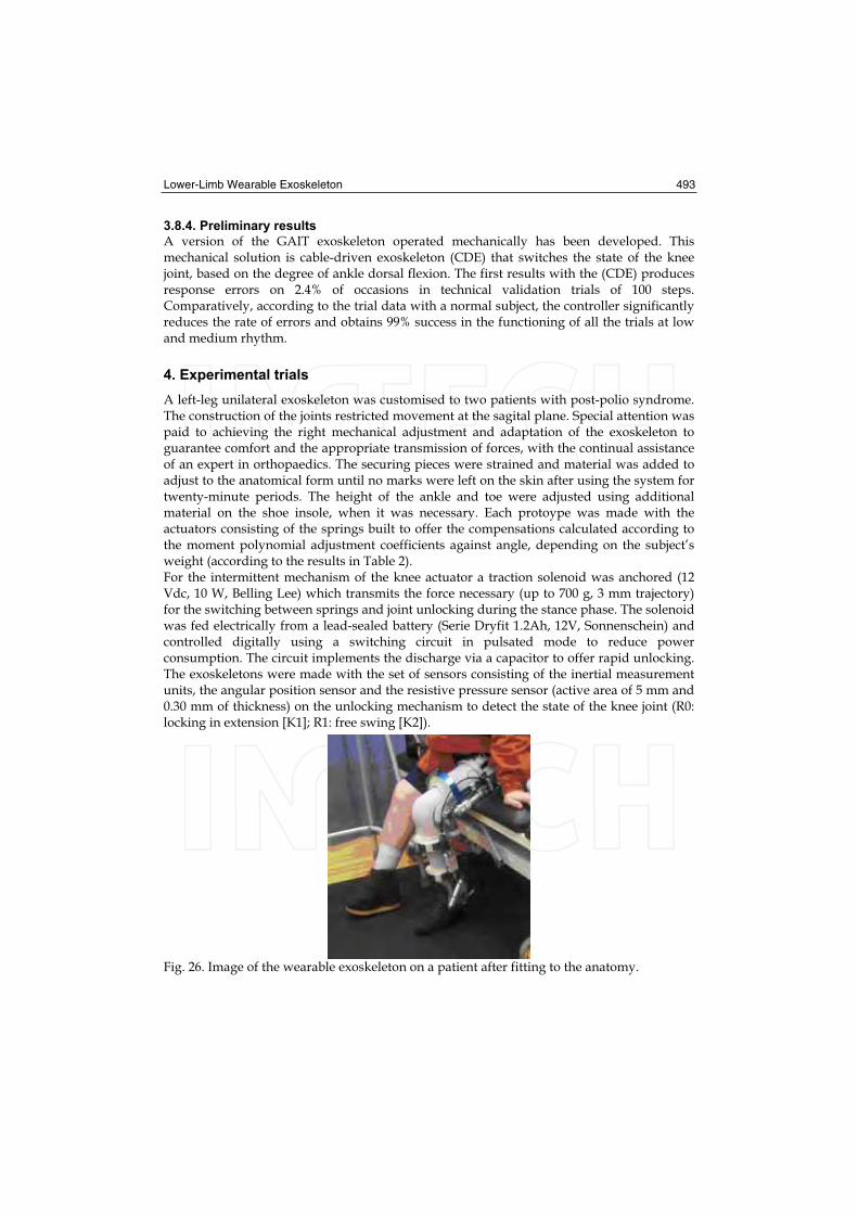
Fig. 26. Image of the wearable exoskeleton on a patient after fitting to the anatomy.
494 Rehabilitation Robotics
The monitoring and control unit included two buttons for direct control by the subjects, offering the possibility of disabling the control strategy and thus totally unlocking the knee at any moment. The exoskeleton with the actuators, batteries, set of sensors and the monitoring and control unit weighed a total of 2.71 Kg. The ambulatory unit (Atmega128, Atmel Inc.; sampling frequency 100 Hz) was used as a real-time control interface with implementation of the control algorithm that generates the real-time control signals (pulses of 12V of amplitude) of activation and activation time of the linear solenoid to compensate gait.
4.1. Protocol
In the first approach of the exoskeleton on the patients the passive prototype version was used which controls the exchange mechanism on the knee actuator using the cable connected to the ankle joint, dorsal flexion control (CDE). With this system functioning the practical session was completed which consisted first of bipedal trials and after walking on flat ground with the patients’ normal aids. One controller was tuned following a sequential procedure from an initial adjustment. The electronically-controlled exoskeleton (ACE) could be disabled remotely from one-base unit at any moment to prevent joint unlocking. Adaptation was expected from the subject after a specific number of trials. In the event that the patient adapted and achieved complete gait cycles, and at the same time increased his/her perception of trust in the body weight support on the exoskeleton (stance phase) and after prior consent, 5 free-gait trials were done with the ACE without external supports.
4.2. Results
4.2.1. Effects on kinematics
Patient S2 usually uses a knee and ankle orthosis to be able to walk. The orthosis has the knee joint locked while the ankle joint restricts plantar flexion and dorsal flexion mobility. The gait pattern with her orthosis is with the knee locked during the stance and swing phases. Immediately after the stance response, there is a dorsal flexion movement greater than normal in the ankle. During the swing phase the foot is protected from the plantar drop with the restriction imposed by the exoskeleton. To put the foot forward, the patient compensates with his body on the transversal and frontal plane. Using the exoskeleton with CDE, subject S2 required a training time of 30 minutes to walk with the crutches instead of standing on the parallel bars used in the first tuning trials of the cable-driven mechanism. After 30 minutes, the patient was able to walk with free swing of the knee (maximum flexion mean of 50°) with the two crutches, and although the speed adopted was low, the knee clearly reaches extension at the end of the swing phase (see Figure 27). After a short time, the patient learnt to manage joint locking at the beginning of stance, used only one crutch and felt sure without any risk of falling. On examining the ankle angle, dorsal flexion, excessive with the subject’s habitual orthosis, progresses appropriately during the stance phase from the action of the ankle actuator. Regarding plantar drop, it is restricted by a maximum of 5° (mean of 4.5°). It was found that assistance to knee extension during the swing phase with the actuator functions considerably well, as can be observed in the mean knee flexions (Table 3).

Lower-Limb Wearable Exoskeleton 495
Fig. 27. Effects (average values) on joint kinematics.
The maximum mean values of knee flexion and ankle flexion for the swing and stance phases are represented in Table 3, and correspond to trials under final training conditions. The number of trials with CDE was reduced to measurements of 5 gait cycles, because of the fatigue problems mentioned earlier.
CDE (5 cycles) ACE (25 cycles)
Peak knee flexion in stance [°] 5.5 ± 2 5.5 ± 1
Peak knee flexion in swing [°] 61 ± 5 61 ± 3
Peak dorsiflexion in stance [°] 6 ± 3 5 ± 2
Peak dorsiflexion in stance [°] 22 ± 5 20 ± 3
Table 3. Mean values of maximum joint flexions for the stance and swing phases under final training conditions.
4.2.2. Kinetics
From the mean values of the ground reaction forces a reduction in mediolateral forces can be observed in patient S1 when automatic gait control is used. In Figure 28 this reduction in mediolateral forces can be observed in the initial stance phase, which avoids lateral movement, typical in the gait of patients with post-polio syndrome.
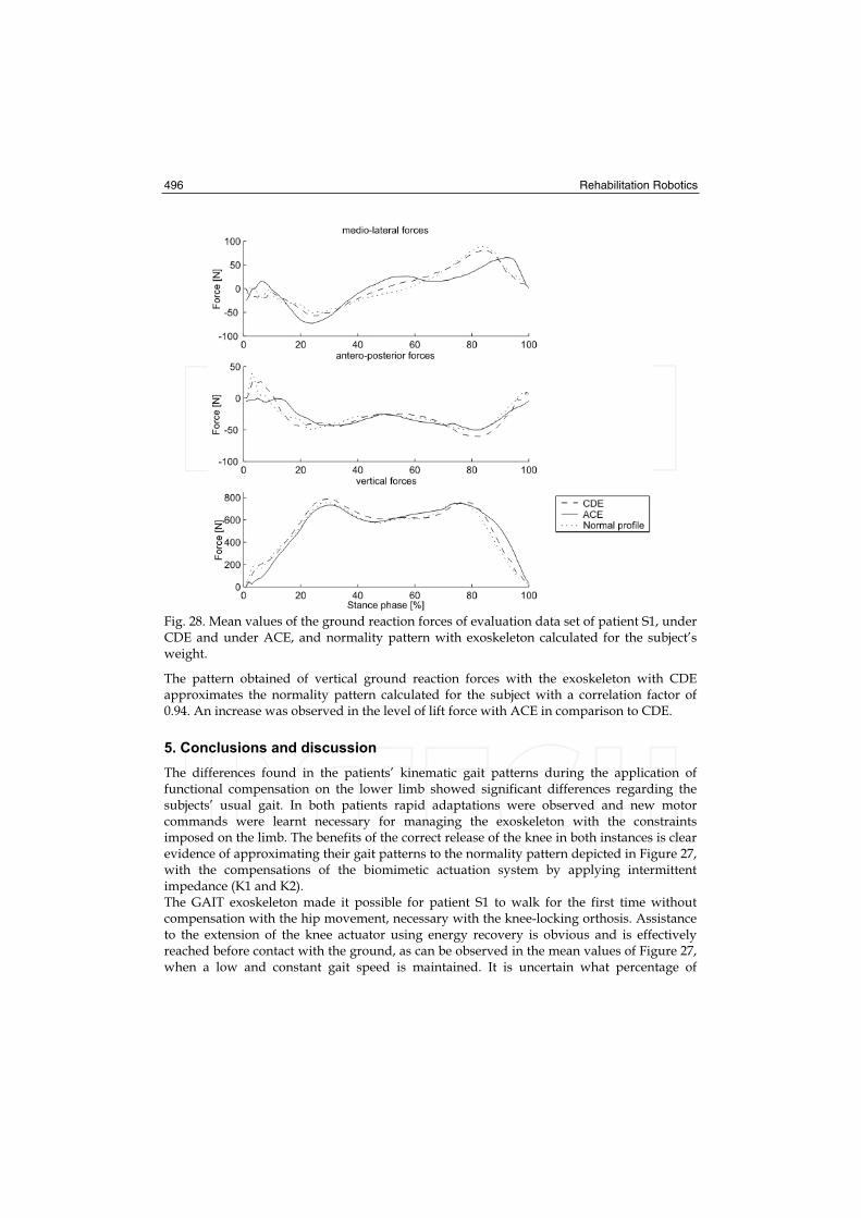
496 Rehabilitation Robotics
Fig. 28. Mean values of the ground reaction forces of evaluation data set of patient S1, under CDE and under ACE, and normality pattern with exoskeleton calculated for the subject’s weight.
The pattern obtained of vertical ground reaction forces with the exoskeleton with CDE approximates the normality pattern calculated for the subject with a correlation factor of 0.94. An increase was observed in the level of lift force with ACE in comparison to CDE.
5. Conclusions and discussion
The differences found in the patients’ kinematic gait patterns during the application of functional compensation on the lower limb showed significant differences regarding the subjects’ usual gait. In both patients rapid adaptations were observed and new motor commands were learnt necessary for managing the exoskeleton with the constraints imposed on the limb. The benefits of the correct release of the knee in both instances is clear evidence of approximating their gait patterns to the normality pattern depicted in Figure 27, with the compensations of the biomimetic actuation system by applying intermittent impedance (K1 and K2). The GAIT exoskeleton made it possible for patient S1 to walk for the first time without compensation with the hip movement, necessary with the knee-locking orthosis. Assistance to the extension of the knee actuator using energy recovery is obvious and is effectively reached before contact with the ground, as can be observed in the mean values of Figure 27, when a low and constant gait speed is maintained. It is uncertain what percentage of
Lower-Limb Wearable Exoskeleton 497
assistance to the knee extension is due to the actuator action and what percentage is determined by movement inertia. It can thus be hypothesised that the recovery spring for extension acts against movement at the beginning of extension.
The results with patient S2 give an indication of the functioning of the ankle actuator for the
partial recovery of energy —stored during stance by the spring with K3— in combination
with the carbon fibre insole recovery of energy in the shoe if the resulting lift forces are
observed with regard to the subject’s insufficient muscular capacity.
The system was designed taking the weight to the most proximal part. Although the
subjects’ first impression was that the system was a slightly heavy, with time this
impression changed and the level of acceptance gradually improved. The cyclical control
gait system applied is based on the speed of rotation of the limbs. It is important to
highlight how at the end of trial, patient S2 preferred to use the ACE and rejected the CDE,
which operates under the same principle of commercial orthotic systems. The importance of
flexibility in the initial adjustment of the algorithm to be customised to the subject’s gait is
clear. In the trials, it was observed that patient S2 had reduced mobility in the ankle, so the
controller conditions were modified and the and , thresholds reduced
to detect the transition moment. It was observed that, although the algorithm monitored the
state of the knee joint in order to avoid undesired activations of the solenoid, this condition
was not sufficient, and it was necessary to change the adjustment of the activation
period consign.
The results found in this study show that the patterns with ambulatory assistance using the
robotic exoskeleton are significantly better than those offered by traditional orthoses or
basic aids. Each pathological case has its own intrinsic characteristics, and the mechanical
adaptation and control system therefore necessitate customisation of the robotic solution.
The evidence obtained with both subjects with post-polio show the viability of the gait
compensation concept using wearable robotic exoskeletons on the improved quality of daily
life in subjects with lower-limb joint disorders.
6. References
Baten, C., de Vries, W., Moreno, J. & Freriks, B (2004). Use of inertial sensing in an intelligent
orthosis. - A feasibility study, Esmac Conference, Warswaw, 2004.
Blaya, J. & Herr, H. (2004b). Adaptive Control of a Variable-Impedance Ankle-Foot Orthosis
to Assist Drop Foot Gait. IEEE Trans Neural Syst Rehabil Eng, Vol. 12, No. 1, (march,
2004), 24-31.
Irby, S., Kaufmaun, K., Wirta, R. & Sutherland, R.. (1999). Optimization and application of a
wrap spring clutch to a dynamic knee-ankle-foot orthosis. IEEE Transactions on
Rehabilitation Engineering, Vol. 7, No. 2, 130-4.
Ferris, D.; Gordon, K., Sawicki, G. & Peethambaran, A. (2006). An improved powered ankle
foot orthosis using proportional myoelectric control. Gait and Posture 23(4), 425-
428.
Ferris, D.; Gordon, K., Sawicki, G. & Peethambaran, A. (2006). An improved powered ankle
foot orthosis using proportional myoelectric control. Gait and Posture 23(4), 425-
428.
Kazerooni, H., Steger, R., & Huang, L. (2003). Hybrid control of the Berkeley lower
extremity exoskeleton. The International Journal of Robotics Research, 25(4-6), 561-573.
498 Rehabilitation Robotics
Moreno, J.C., Rocon E., Ruiz, A., Brunetti, F., & Pons, J.L. (2006b). Design and implementation of an inertial measurement unit for control of artificial limbs: application on leg orthoses. Sensors and Actuators B, 118(1-2), 333-337.
Moreno, J.C., Brunetti, F., Cullell, A., Forner-Cordero, A. & Pons, J.L. (2006c). Simulation Of Knee Function During Gait With An Orthosis By Means Of Two Springs Of Different Stifnesses. Gait and Posture, 21(Sup1), S140.
Rehbinder H. and Martin C. (2001). A control theoretic model of the fore arm. Journal of Biomechanics 34(6), 741-748.
Rocon, E., Belda-Lois, J.M., Sánchez-Lacuesta, J.J., Ruiz, A.F. & Pons, J.L. (2005b). Estimation of biomechanical characteristics of tremorous movements based on gyroscopes. In: Asistive Technology - from Virtuality to Reality. AAATE05. Lille , France.
Winter, D.A. (1991). The biomechanics and motor control of human movement, University of Waterloo, 2nd edition.
Rehabilitation RoboticsEdited by Sashi S Kommu
ISBN 978-3-902613-04-2Hard cover, 648 pagesPublisher I-Tech Education and PublishingPublished online 01, August, 2007Published in print edition August, 2007
InTech EuropeUniversity Campus STeP Ri Slavka Krautzeka 83/A 51000 Rijeka, Croatia Phone: +385 (51) 770 447 Fax: +385 (51) 686 166www.intechopen.com
InTech ChinaUnit 405, Office Block, Hotel Equatorial Shanghai No.65, Yan An Road (West), Shanghai, 200040, China
Phone: +86-21-62489820 Fax: +86-21-62489821
The coupling of several areas of the medical field with recent advances in robotic systems has seen aparadigm shift in our approach to selected sectors of medical care, especially over the last decade.Rehabilitation medicine is one such area. The development of advanced robotic systems has ushered with itan exponential number of trials and experiments aimed at optimising restoration of quality of life to those whoare physically debilitated. Despite these developments, there remains a paucity in the presentation of theseadvances in the form of a comprehensive tool. This book was written to present the most recent advances inrehabilitation robotics known to date from the perspective of some of the leading experts in the field andpresents an interesting array of developments put into 33 comprehensive chapters. The chapters arepresented in a way that the reader will get a seamless impression of the current concepts of optimal modes ofboth experimental and ap- plicable roles of robotic devices.
How to referenceIn order to correctly reference this scholarly work, feel free to copy and paste the following:
J.L. Pons, J.C. Moreno, F.J. Brunetti and E. Rocon (2007). Lower-Limb Wearable Exoskeleton, RehabilitationRobotics, Sashi S Kommu (Ed.), ISBN: 978-3-902613-04-2, InTech, Available from:http://www.intechopen.com/books/rehabilitation_robotics/lower-limb_wearable_exoskeleton