low voltage ac drives abb micro drives 0.5 to 5 hp/0.37 to 4 · pdf filecatalog | abb micro...
TRANSCRIPT
ABB micro drivesACS150 0.5 to 5 hp/0.37 to 4 kWCatalog
Low voltage AC drives
2 ABB micro drives ACS150 | Catalog
Introduction to ACS150
ABB micro drives
ACS150 variable frequency drives feature an integrated control
panel with LCD display and built-in speed potentiometer. For
easy setup and commissioning, the drives include a variety of
predefined I/O configuration macros including: ABB standard,
3-wire control, Digital input control, PID control, Hand/
Auto control, and a PLC interface. User defined macros can
also be created. The ACS150 drive has an extensive list of
programmable drive parameters that are used to achieve high
performance with maximum versatility in many applications.
ACS150 micro drives are compact with multiple mounting
positions and options. The built-in DIN rail mounting capability
makes them ideal for panel builders. Rapid programming and
commissioning are possible using the on board setup macros.
The DrivePM (Drive Parameter Manager) software tool can be
used to create, edit, and copy parameter sets using the
MFDT-01 FlashDrop tool.
Flashdrop, an optional drive configuration tool, can be used
to quickly and easily configure spares or large volumes of
unpowered drives using the connection port on the front
panel. FlashDrop stores up to 20 different parameter sets and
can copy parameters from one drive to another, or between a
PC and a drive.
Feature Advantage Benefit
Worldwide availability and service Drives are available worldwide and permanently stocked in four
regions.
Dedicated global service and support network that is one of the
widest in the industry.
Fast and reliable delivery with dedicated
support to any country in the world.
User-friendly LCD control panel and
integrated potentiometer
Clear alphanumeric display. Easy setup and use. Time savings due to quick setup and simple
configuration.
Flexible mounting alternatives Screw or DIN rail mounting, sideways or side-by-side. One drive type can be used in various
designs, saving installation costs and time.
Integrated EMC filter High electromagnetic compatibility. Low EMC emissions in selected environments.
Built-in brake chopper as standard No need for an external brake chopper. Space savings, reduced installation cost.
FlashDrop tool Faster and easier drive setup and commissioning for volume
manufacturing and maintenance. The FlashDrop tool enables
both downloading and uploading drive parameters.
Fast, safe and trouble-free parameter setting
without the need to power-up the drive.
Patented.
PID control Varies the drive’s performance according to the need of the
application.
Enhances production output, stability and
accuracy.
Coated boards Board coating protects the electronics from hazards including
static discharge and airborne contaminates, including moisture.
Reduces maintenance due to good protection
of electronics components.
The ACS150 drive is ideal for panel builders and OEM’s needing
a micro drive with low cost, flexible mounting options, and rapid
parameter setup.
Highlights
– Power range: 0.50 to 5 Hp, single and three phase input
– 150% peak overload capacity
– Worldwide availability and support
– User-friendly control panel with LCD display and integrated
potentiometer
– Multiple mounting positions
– PID control
– Integrated 2nd environment EMC filter with disconnect option
– Built-in brake chopper
– Flashdrop tool for fast commissioning
– Conformally coated boards
– Common height and depth across the product line, for
flexible installation
– Wall or DIN rail mountable
– Easy access to power and I/O connections for rapid
installation
– Selection options for input reactors, output filters, & braking
resistors
– UL listing includes use of ABB manual motor protectors for
branch circuit protection instead of fuses
Catalog | ABB micro drives ACS150 3
Easily integrated drives for a wide range of applications
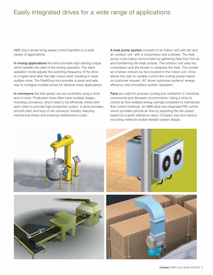
ABB micro drives bring speed control benefits to a wide
variety of applications.
In mixing applications the drive provides high starting torque
which benefi ts the start of the mixing operation. The silent
operation mode adjusts the switching frequency of the drive
to a higher level after the high-torque start, resulting in lower
audible noise. The FlashDrop tool provides a quick and safe
way to confi gure multiple drives for identical mixer applications.
In conveyors the belt speed can be controlled using a drive
and a motor. Production lines often have multiple stages,
including conveyors, which need to be efficiently linked with
each other to provide high production output. A drive provides
smooth start and stop of the conveyor, thereby reducing
mechanical stress and lowering maintenance costs.
A heat pump system consists of an indoor unit with fan and
an outdoor unit with a compressor and a blower. The heat
pump cools indoor environment by gathering heat from the air,
and transferring the heat outside. The outdoor unit uses the
compressor and the blower to dissipate the heat. The cooled
air is blown indoors by fans located in the indoor unit. Drive
allows the user to variably control the cooling power based
on customer request. AC drives optimizes systems’ energy
efficiency and smoothens system operation.
Fans are used for process cooling and ventilation in industrial,
commercial and domestic environments. Using a drive to
control air fl ow enables energy savings compared to mechanical
fl ow control methods. An ABB drive has integrated PID control
which provides optimal air flow by adjusting the fan speed
based on a given reference value. Compact size and various
mounting methods enable flexible system design.
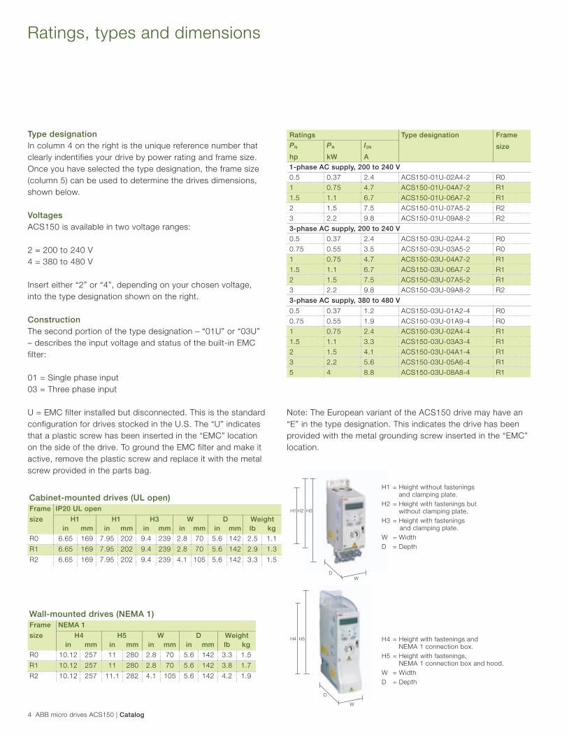
H1 H2 H3
D
W
H4 H5
D
W
4 ABB micro drives ACS150 | Catalog
Ratings, types and dimensions
Type designation
In column 4 on the right is the unique reference number that
clearly indentifies your drive by power rating and frame size.
Once you have selected the type designation, the frame size
(column 5) can be used to determine the drives dimensions,
shown below.
Voltages
ACS150 is available in two voltage ranges:
2 = 200 to 240 V
4 = 380 to 480 V
Insert either “2” or “4”, depending on your chosen voltage,
into the type designation shown on the right.
Construction
The second portion of the type designation – “01U” or “03U”
– describes the input voltage and status of the built-in EMC
filter:
01 = Single phase input
03 = Three phase input
U = EMC filter installed but disconnected. This is the standard
configuration for drives stocked in the U.S. The “U” indicates
that a plastic screw has been inserted in the “EMC” location
on the side of the drive. To ground the EMC filter and make it
active, remove the plastic screw and replace it with the metal
screw provided in the parts bag.
Ratings Type designation Frame
sizePN
hp
PN
kW
I2N
A
1-phase AC supply, 200 to 240 V
0.5 0.37 2.4 ACS150-01U-02A4-2 R0
1 0.75 4.7 ACS150-01U-04A7-2 R1
1.5 1.1 6.7 ACS150-01U-06A7-2 R1
2 1.5 7.5 ACS150-01U-07A5-2 R2
3 2.2 9.8 ACS150-01U-09A8-2 R2
3-phase AC supply, 200 to 240 V
0.5 0.37 2.4 ACS150-03U-02A4-2 R0
0.75 0.55 3.5 ACS150-03U-03A5-2 R0
1 0.75 4.7 ACS150-03U-04A7-2 R1
1.5 1.1 6.7 ACS150-03U-06A7-2 R1
2 1.5 7.5 ACS150-03U-07A5-2 R1
3 2.2 9.8 ACS150-03U-09A8-2 R2
3-phase AC supply, 380 to 480 V
0.5 0.37 1.2 ACS150-03U-01A2-4 R0
0.75 0.55 1.9 ACS150-03U-01A9-4 R0
1 0.75 2.4 ACS150-03U-02A4-4 R1
1.5 1.1 3.3 ACS150-03U-03A3-4 R1
2 1.5 4.1 ACS150-03U-04A1-4 R1
3 2.2 5.6 ACS150-03U-05A6-4 R1
5 4 8.8 ACS150-03U-08A8-4 R1
H1 = Height without fastenings
and clamping plate.
H2 = Height with fastenings but
without clamping plate.
H3 = Height with fastenings
and clamping plate.
W = Width
D = Depth
H4 = Height with fastenings and
NEMA 1 connection box.
H5 = Height with fastenings,
NEMA 1 connection box and hood.
W = Width
D = Depth
Cabinet-mounted drives (UL open)
Frame IP20 UL open
size H1 H1 H3 W D Weight
in mm in mm in mm in mm in mm lb kg
R0 6.65 169 7.95 202 9.4 239 2.8 70 5.6 142 2.5 1.1
R1 6.65 169 7.95 202 9.4 239 2.8 70 5.6 142 2.9 1.3
R2 6.65 169 7.95 202 9.4 239 4.1 105 5.6 142 3.3 1.5
Wall-mounted drives (NEMA 1)
Frame NEMA 1
size H4 H5 W D Weight
in mm in mm in mm in mm lb kg
R0 10.12 257 11 280 2.8 70 5.6 142 3.3 1.5
R1 10.12 257 11 280 2.8 70 5.6 142 3.8 1.7
R2 10.12 257 11.1 282 4.1 105 5.6 142 4.2 1.9
Note: The European variant of the ACS150 drive may have an
“E” in the type designation. This indicates the drive has been
provided with the metal grounding screw inserted in the “EMC”
location.
Catalog | ABB micro drives ACS150 5
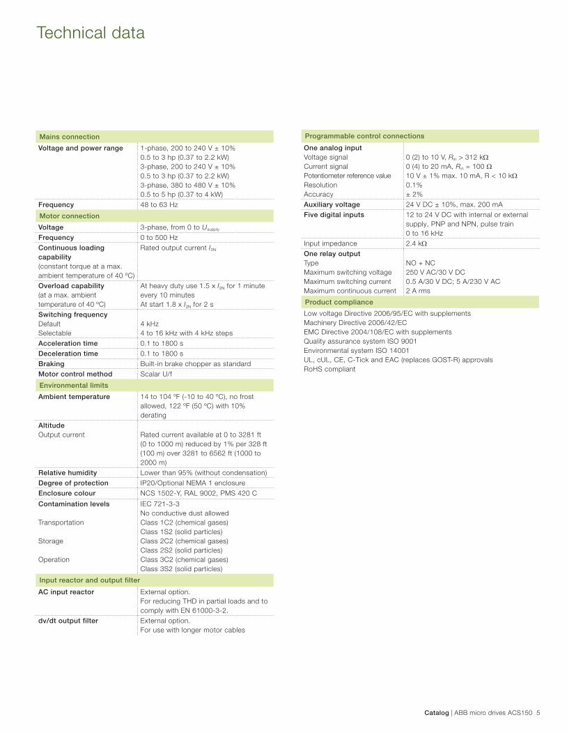
Technical data
Mains connection
Voltage and power range 1-phase, 200 to 240 V ± 10%
0.5 to 3 hp (0.37 to 2.2 kW)
3-phase, 200 to 240 V ± 10%
0.5 to 3 hp (0.37 to 2.2 kW)
3-phase, 380 to 480 V ± 10%
0.5 to 5 hp (0.37 to 4 kW)
Frequency 48 to 63 Hz
Motor connection
Voltage 3-phase, from 0 to Usupply
Frequency 0 to 500 Hz
Continuous loading
capability
(constant torque at a max.
ambient temperature of 40 ºC)
Rated output current I2N
Overload capability
(at a max. ambient
temperature of 40 ºC)
At heavy duty use 1.5 x I2N for 1 minute
every 10 minutes
At start 1.8 x I2N for 2 s
Switching frequency
Default
Selectable
4 kHz
4 to 16 kHz with 4 kHz steps
Acceleration time 0.1 to 1800 s
Deceleration time 0.1 to 1800 s
Braking Built-in brake chopper as standard
Motor control method Scalar U/f
Environmental limits
Ambient temperature 14 to 104 ºF (-10 to 40 ºC), no frost
allowed, 122 ºF (50 ºC) with 10%
derating
Altitude
Output current Rated current available at 0 to 3281 ft
(0 to 1000 m) reduced by 1% per 328 ft
(100 m) over 3281 to 6562 ft (1000 to
2000 m)
Relative humidity Lower than 95% (without condensation)
Degree of protection IP20/Optional NEMA 1 enclosure
Enclosure colour NCS 1502-Y, RAL 9002, PMS 420 C
Contamination levels
Transportation
Storage
Operation
IEC 721-3-3
No conductive dust allowed
Class 1C2 (chemical gases)
Class 1S2 (solid particles)
Class 2C2 (chemical gases)
Class 2S2 (solid particles)
Class 3C2 (chemical gases)
Class 3S2 (solid particles)
Input reactor and output filter
AC input reactor External option.
For re duc ing THD in partial loads and to
comply with EN 61000-3-2.
dv/dt output filter External option.
For use with longer motor cables
Programmable control connections
One analog input
Voltage signal
Current signal
Potentiometer reference value
Resolution
Accuracy
0 (2) to 10 V, Rin > 312 k0 (4) to 20 mA, Rin = 100 10 V ± 1% max. 10 mA, R < 10 k0.1%
± 2%
Auxiliary voltage 24 V DC ± 10%, max. 200 mA
Five digital inputs 12 to 24 V DC with internal or external
supply, PNP and NPN, pulse train
0 to 16 kHz
Input impedance 2.4 kOne relay output
Type
Maximum switching voltage
Maximum switching current
Maximum continuous current
NO + NC
250 V AC/30 V DC
0.5 A/30 V DC; 5 A/230 V AC
2 A rms
Product compliance
Low voltage Directive 2006/95/EC with supplements
Machinery Directive 2006/42/EC
EMC Directive 2004/108/EC with supplements
Quality assurance system ISO 9001
Environmental system ISO 14001
UL, cUL, CE, C-Tick and EAC (replaces GOST-R) approvals
RoHS compliant
6 ABB micro drives ACS150 | Catalog
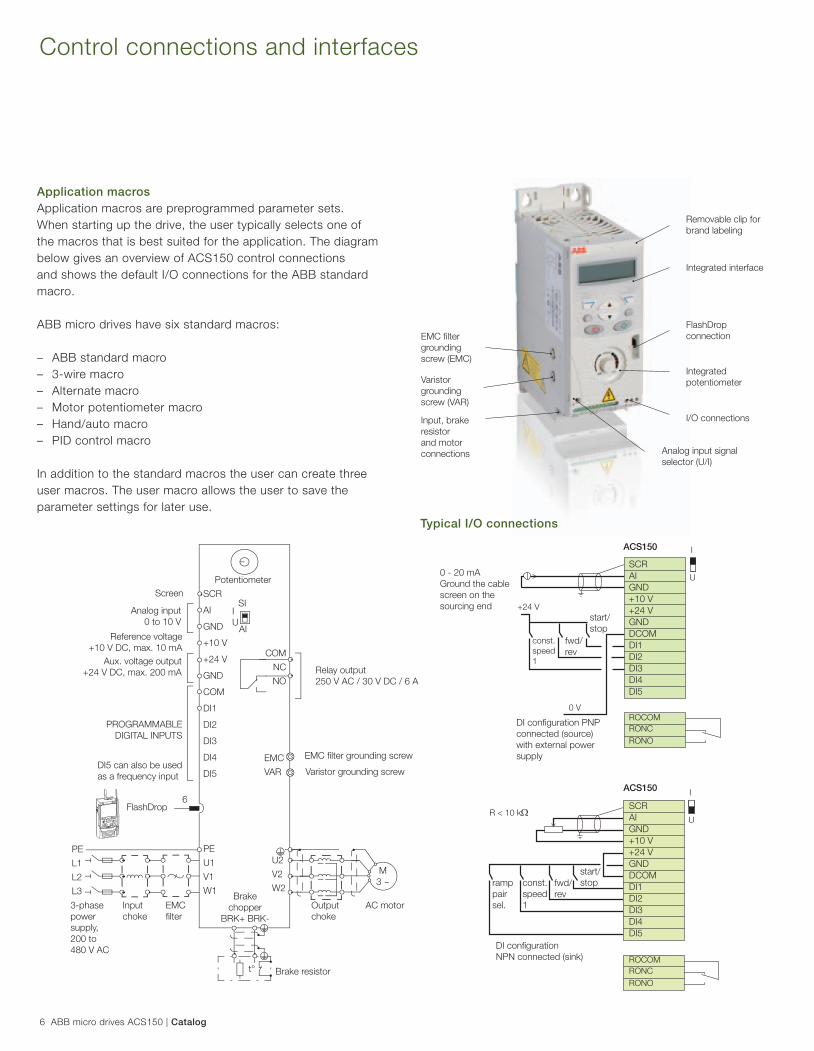
Control connections and interfaces
Application macros
Application macros are preprogrammed parameter sets.
When starting up the drive, the user typically selects one of
the macros that is best suited for the application. The diagram
below gives an overview of ACS150 control connections
and shows the default I/O connections for the ABB standard
macro.
ABB micro drives have six standard macros:
– ABB standard macro
– 3-wire macro
– Alternate macro
– Motor potentiometer macro
– Hand/auto macro
– PID control macro
In addition to the standard macros the user can create three
user macros. The user macro allows the user to save the
parameter settings for later use.
EMC fi lter
grounding
screw (EMC)
Removable clip for
brand labeling
Integrated interface
FlashDrop
connection
Integrated
potentiometer
I/O connections
Varistor
grounding
screw (VAR)
Analog input signal
selector (U/I)
Input, brake
resistor
and motor
connections
ROCOM
RONC
RONO
+24 V
0 V
const.
speed
1
I
U
I
UR < 10 k
SCR
AI
GND
+10 V
+24 V
GND
DCOM
DI1
DI2
DI3
DI4
DI5
ramp
pair
sel.
const.
speed
1
fwd/
rev
start/
stop
DI confi guration
NPN connected (sink)
ACS150
ACS150
SCR
AI
GND
+10 V
+24 V
GND
DCOM
DI1
DI2
DI3
DI4
DI5
start/
stop
fwd/
rev
DI confi guration PNP
connected (source)
with external power
supply
0 - 20 mA
Ground the cable
screen on the
sourcing end
Screen
Potentiometer
Analog input
0 to 10 V
Reference voltage
+10 V DC, max. 10 mA
Aux. voltage output
+24 V DC, max. 200 mA
PROGRAMMABLE
DIGITAL INPUTS
DI5 can also be used
as a frequency input
FlashDrop6
PE
L1
L2
L3
3-phase
power
supply,
200 to
480 V AC
Input
choke
EMC
fi lter
Output
choke
PE
U1
V1
W1
U2
V2
W2
EMC
VAR
SCR
AI
GND
+10 V
+24 V
GND
COM
DI1
DI2
DI3
DI4
DI5
COM
NC
NO
AC motor
M
3 ~
Brake
chopper
BRK+ BRK-
Brake resistort°
SI
AI
I
U
EMC fi lter grounding screw
Relay output
250 V AC / 30 V DC / 6 A
Varistor grounding screw
Typical I/O connections
ROCOM
RONC
RONO
Catalog | ABB micro drives ACS150 7
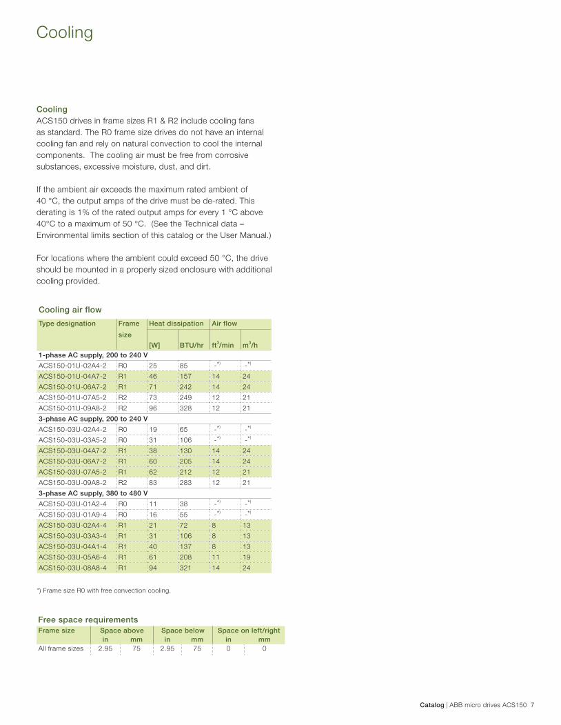
Cooling
Cooling
ACS150 drives in frame sizes R1 & R2 include cooling fans
as standard. The R0 frame size drives do not have an internal
cooling fan and rely on natural convection to cool the internal
components. The cooling air must be free from corrosive
substances, excessive moisture, dust, and dirt.
If the ambient air exceeds the maximum rated ambient of
40 °C, the output amps of the drive must be de-rated. This
derating is 1% of the rated output amps for every 1 °C above
40°C to a maximum of 50 °C. (See the Technical data –
Environmental limits section of this catalog or the User Manual.)
For locations where the ambient could exceed 50 °C, the drive
should be mounted in a properly sized enclosure with additional
cooling provided.
*) Frame size R0 with free convection cooling.
Cooling air flow
Type designation Frame
size
Heat dissipation Air flow
[W] BTU/hr ft3/min m
3/h
1-phase AC supply, 200 to 240 V
ACS150-01U-02A4-2 R0 25 85 -*)
-*)
ACS150-01U-04A7-2 R1 46 157 14 24
ACS150-01U-06A7-2 R1 71 242 14 24
ACS150-01U-07A5-2 R2 73 249 12 21
ACS150-01U-09A8-2 R2 96 328 12 21
3-phase AC supply, 200 to 240 V
ACS150-03U-02A4-2 R0 19 65 -*)
-*)
ACS150-03U-03A5-2 R0 31 106 -*)
-*)
ACS150-03U-04A7-2 R1 38 130 14 24
ACS150-03U-06A7-2 R1 60 205 14 24
ACS150-03U-07A5-2 R1 62 212 12 21
ACS150-03U-09A8-2 R2 83 283 12 21
3-phase AC supply, 380 to 480 V
ACS150-03U-01A2-4 R0 11 38 -*)
-*)
ACS150-03U-01A9-4 R0 16 55 -*)
-*)
ACS150-03U-02A4-4 R1 21 72 8 13
ACS150-03U-03A3-4 R1 31 106 8 13
ACS150-03U-04A1-4 R1 40 137 8 13
ACS150-03U-05A6-4 R1 61 208 11 19
ACS150-03U-08A8-4 R1 94 321 14 24
Free space requirements
Frame size Space above Space below Space on left/right
in mm in mm in mm
All frame sizes 2.95 75 2.95 75 0 0
8 ABB micro drives ACS150 | Catalog
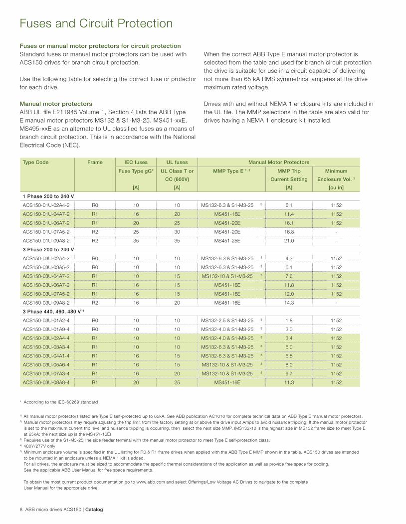
Type Code Frame IEC fuses UL fuses Manual Motor Protectors
Fuse Type gG*
[A]
UL Class T or
CC (600V)
[A]
MMP Type E 1, 2 MMP Trip
Current Setting
[A]
Minimum
Enclosure Vol. 5
[cu in]
1 Phase 200 to 240 V
ACS150-01U-02A4-2 R0 10 10 MS132-6.3 & S1-M3-25 3 6.1 1152
ACS150-01U-04A7-2 R1 16 20 MS451-16E 11.4 1152
ACS150-01U-06A7-2 R1 20 25 MS451-20E 16.1 1152
ACS150-01U-07A5-2 R2 25 30 MS451-20E 16.8 -
ACS150-01U-09A8-2 R2 35 35 MS451-25E 21.0 -
3 Phase 200 to 240 V
ACS150-03U-02A4-2 R0 10 10 MS132-6.3 & S1-M3-25 3 4.3 1152
ACS150-03U-03A5-2 R0 10 10 MS132-6.3 & S1-M3-25 3 6.1 1152
ACS150-03U-04A7-2 R1 10 15 MS132-10 & S1-M3-25 3 7.6 1152
ACS150-03U-06A7-2 R1 16 15 MS451-16E 11.8 1152
ACS150-03U-07A5-2 R1 16 15 MS451-16E 12.0 1152
ACS150-03U-09A8-2 R2 16 20 MS451-16E 14.3 -
3 Phase 440, 460, 480 V 4
ACS150-03U-01A2-4 R0 10 10 MS132-2.5 & S1-M3-25 3 1.8 1152
ACS150-03U-01A9-4 R0 10 10 MS132-4.0 & S1-M3-25 3 3.0 1152
ACS150-03U-02A4-4 R1 10 10 MS132-4.0 & S1-M3-25 3 3.4 1152
ACS150-03U-03A3-4 R1 10 10 MS132-6.3 & S1-M3-25 3 5.0 1152
ACS150-03U-04A1-4 R1 16 15 MS132-6.3 & S1-M3-25 3 5.8 1152
ACS150-03U-05A6-4 R1 16 15 MS132-10 & S1-M3-25 3 8.0 1152
ACS150-03U-07A3-4 R1 16 20 MS132-10 & S1-M3-25 3 9.7 1152
ACS150-03U-08A8-4 R1 20 25 MS451-16E 11.3 1152
Fuses and Circuit Protection
* According to the IEC-60269 standard
1) All manual motor protectors listed are Type E self-protected up to 65kA. See ABB publication AC1010 for complete technical data on ABB Type E manual motor protectors.2) Manual motor protectors may require adjusting the trip limit from the factory setting at or above the drive input Amps to avoid nuisance tripping. If the manual motor protector
is set to the maximum current trip level and nuisance tripping is occurring, then select the next size MMP. (MS132-10 is the highest size in MS132 frame size to meet Type E
at 65kA; the next size up is the MS451-16E)3) Requires use of the S1-M3-25 line side feeder terminal with the manual motor protector to meet Type E self-protection class.4) 480Y/277V only5) Minimum enclosure volume is specified in the UL listing for R0 & R1 frame drives when applied with the ABB Type E MMP shown in the table. ACS150 drives are intended
to be mounted in an enclosure unless a NEMA 1 kit is added.
For all drives, the enclosure must be sized to accommodate the specific thermal considerations of the application as well as provide free space for cooling.
See the applicable ABB User Manual for free space requirements.
To obtain the most current product documentation go to www.abb.com and select Offerings/Low Voltage AC Drives to navigate to the complete
User Manual for the appropriate drive.
Fuses or manual motor protectors for circuit protection
Standard fuses or manual motor protectors can be used with
ACS150 drives for branch circuit protection.
Use the following table for selecting the correct fuse or protector
for each drive.
Manual motor protectors
ABB UL file E211945 Volume 1, Section 4 lists the ABB Type
E manual motor protectors MS132 & S1-M3-25, MS451-xxE,
MS495-xxE as an alternate to UL classified fuses as a means of
branch circuit protection. This is in accordance with the National
Electrical Code (NEC).
When the correct ABB Type E manual motor protector is
selected from the table and used for branch circuit protection
the drive is suitable for use in a circuit capable of delivering
not more than 65 kA RMS symmetrical amperes at the drive
maximum rated voltage.
Drives with and without NEMA 1 enclosure kits are included in
the UL file. The MMP selections in the table are also valid for
drives having a NEMA 1 enclosure kit installed.
Catalog | ABB micro drives ACS150 9
Options
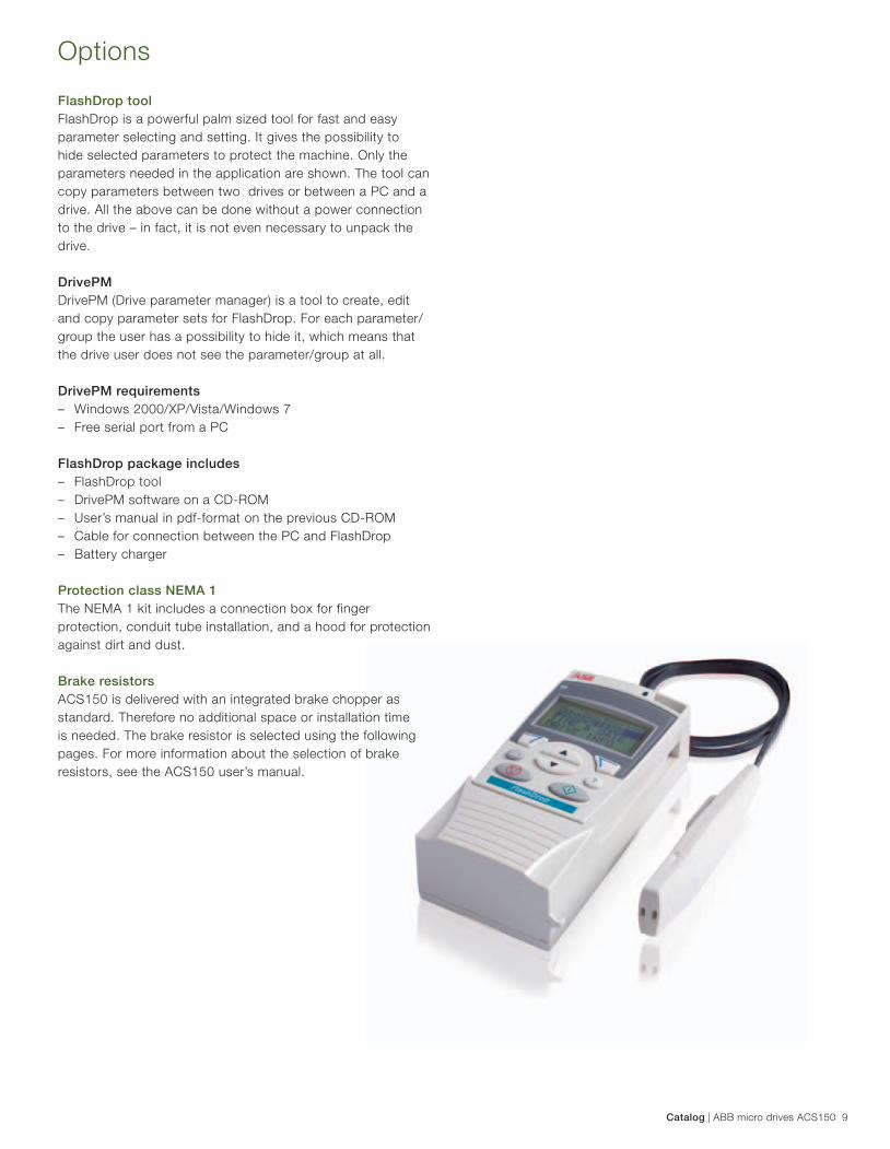
FlashDrop tool
FlashDrop is a powerful palm sized tool for fast and easy
parameter selecting and setting. It gives the possibility to
hide selected parameters to protect the machine. Only the
parameters needed in the application are shown. The tool can
copy parameters between two drives or between a PC and a
drive. All the above can be done without a power connection
to the drive – in fact, it is not even necessary to unpack the
drive.
DrivePM
DrivePM (Drive parameter manager) is a tool to create, edit
and copy parameter sets for FlashDrop. For each parameter/
group the user has a possibility to hide it, which means that
the drive user does not see the parameter/group at all.
DrivePM requirements
– Windows 2000/XP/Vista/Windows 7
– Free serial port from a PC
FlashDrop package includes
– FlashDrop tool
– DrivePM software on a CD-ROM
– User’s manual in pdf-format on the previous CD-ROM
– Cable for connection between the PC and FlashDrop
– Battery charger
Protection class NEMA 1
The NEMA 1 kit includes a connection box for finger
protection, conduit tube installation, and a hood for protection
against dirt and dust.
Brake resistors
ACS150 is delivered with an integrated brake chopper as
standard. Therefore no additional space or installation time
is needed. The brake resistor is selected using the following
pages. For more information about the selection of brake
resistors, see the ACS150 user’s manual.
10 ABB micro drives ACS150 | Catalog
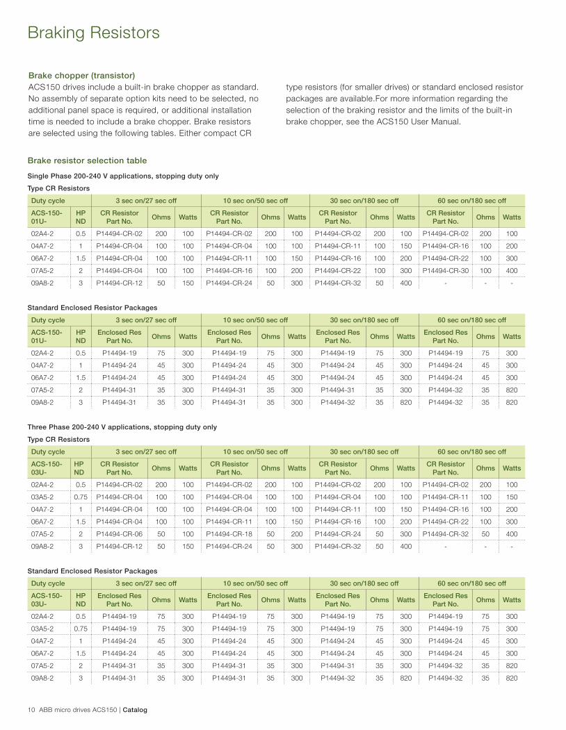
Brake chopper (transistor)
ACS150 drives include a built-in brake chopper as standard.
No assembly of separate option kits need to be selected, no
additional panel space is required, or additional installation
time is needed to include a brake chopper. Brake resistors
are selected using the following tables. Either compact CR
Braking Resistors
Single Phase 200-240 V applications, stopping duty only
Type CR Resistors
Duty cycle 3 sec on/27 sec off 10 sec on/50 sec off 30 sec on/180 sec off 60 sec on/180 sec off
ACS-150-01U-
HP ND
CR Resistor Part No.
Ohms WattsCR Resistor
Part No.Ohms Watts
CR Resistor Part No.
Ohms WattsCR Resistor
Part No.Ohms Watts
02A4-2 0.5 P14494-CR-02 200 100 P14494-CR-02 200 100 P14494-CR-02 200 100 P14494-CR-02 200 100
04A7-2 1 P14494-CR-04 100 100 P14494-CR-04 100 100 P14494-CR-11 100 150 P14494-CR-16 100 200
06A7-2 1.5 P14494-CR-04 100 100 P14494-CR-11 100 150 P14494-CR-16 100 200 P14494-CR-22 100 300
07A5-2 2 P14494-CR-04 100 100 P14494-CR-16 100 200 P14494-CR-22 100 300 P14494-CR-30 100 400
09A8-2 3 P14494-CR-12 50 150 P14494-CR-24 50 300 P14494-CR-32 50 400 - - -
Standard Enclosed Resistor Packages
Duty cycle 3 sec on/27 sec off 10 sec on/50 sec off 30 sec on/180 sec off 60 sec on/180 sec off
ACS-150-01U-
HP ND
Enclosed Res Part No.
Ohms WattsEnclosed Res
Part No.Ohms Watts
Enclosed Res Part No.
Ohms WattsEnclosed Res
Part No.Ohms Watts
02A4-2 0.5 P14494-19 75 300 P14494-19 75 300 P14494-19 75 300 P14494-19 75 300
04A7-2 1 P14494-24 45 300 P14494-24 45 300 P14494-24 45 300 P14494-24 45 300
06A7-2 1.5 P14494-24 45 300 P14494-24 45 300 P14494-24 45 300 P14494-24 45 300
07A5-2 2 P14494-31 35 300 P14494-31 35 300 P14494-31 35 300 P14494-32 35 820
09A8-2 3 P14494-31 35 300 P14494-31 35 300 P14494-32 35 820 P14494-32 35 820
Three Phase 200-240 V applications, stopping duty only
Type CR Resistors
Duty cycle 3 sec on/27 sec off 10 sec on/50 sec off 30 sec on/180 sec off 60 sec on/180 sec off
ACS-150-03U-
HP ND
CR Resistor Part No.
Ohms WattsCR Resistor
Part No.Ohms Watts
CR Resistor Part No.
Ohms WattsCR Resistor
Part No.Ohms Watts
02A4-2 0.5 P14494-CR-02 200 100 P14494-CR-02 200 100 P14494-CR-02 200 100 P14494-CR-02 200 100
03A5-2 0.75 P14494-CR-04 100 100 P14494-CR-04 100 100 P14494-CR-04 100 100 P14494-CR-11 100 150
04A7-2 1 P14494-CR-04 100 100 P14494-CR-04 100 100 P14494-CR-11 100 150 P14494-CR-16 100 200
06A7-2 1.5 P14494-CR-04 100 100 P14494-CR-11 100 150 P14494-CR-16 100 200 P14494-CR-22 100 300
07A5-2 2 P14494-CR-06 50 100 P14494-CR-18 50 200 P14494-CR-24 50 300 P14494-CR-32 50 400
09A8-2 3 P14494-CR-12 50 150 P14494-CR-24 50 300 P14494-CR-32 50 400 - - -
Standard Enclosed Resistor Packages
Duty cycle 3 sec on/27 sec off 10 sec on/50 sec off 30 sec on/180 sec off 60 sec on/180 sec off
ACS-150-03U-
HP ND
Enclosed Res Part No.
Ohms WattsEnclosed Res
Part No.Ohms Watts
Enclosed Res Part No.
Ohms WattsEnclosed Res
Part No.Ohms Watts
02A4-2 0.5 P14494-19 75 300 P14494-19 75 300 P14494-19 75 300 P14494-19 75 300
03A5-2 0.75 P14494-19 75 300 P14494-19 75 300 P14494-19 75 300 P14494-19 75 300
04A7-2 1 P14494-24 45 300 P14494-24 45 300 P14494-24 45 300 P14494-24 45 300
06A7-2 1.5 P14494-24 45 300 P14494-24 45 300 P14494-24 45 300 P14494-24 45 300
07A5-2 2 P14494-31 35 300 P14494-31 35 300 P14494-31 35 300 P14494-32 35 820
09A8-2 3 P14494-31 35 300 P14494-31 35 300 P14494-32 35 820 P14494-32 35 820
type resistors (for smaller drives) or standard enclosed resistor
packages are available.For more information regarding the
selection of the braking resistor and the limits of the built-in
brake chopper, see the ACS150 User Manual.
Brake resistor selection table
Catalog | ABB micro drives ACS150 11
Braking Resistors
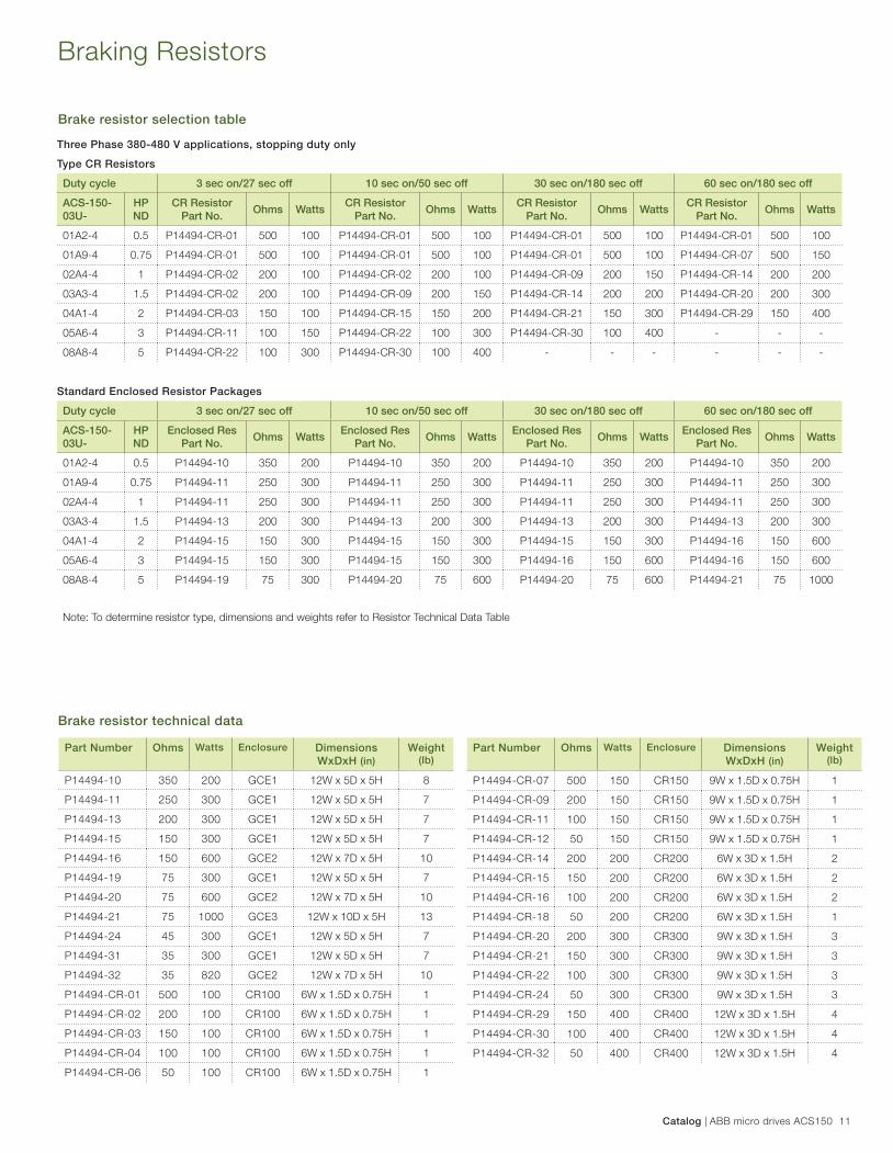
Three Phase 380-480 V applications, stopping duty only
Type CR Resistors
Duty cycle 3 sec on/27 sec off 10 sec on/50 sec off 30 sec on/180 sec off 60 sec on/180 sec off
ACS-150-03U-
HP ND
CR Resistor Part No.
Ohms WattsCR Resistor
Part No.Ohms Watts
CR Resistor Part No.
Ohms WattsCR Resistor
Part No.Ohms Watts
01A2-4 0.5 P14494-CR-01 500 100 P14494-CR-01 500 100 P14494-CR-01 500 100 P14494-CR-01 500 100
01A9-4 0.75 P14494-CR-01 500 100 P14494-CR-01 500 100 P14494-CR-01 500 100 P14494-CR-07 500 150
02A4-4 1 P14494-CR-02 200 100 P14494-CR-02 200 100 P14494-CR-09 200 150 P14494-CR-14 200 200
03A3-4 1.5 P14494-CR-02 200 100 P14494-CR-09 200 150 P14494-CR-14 200 200 P14494-CR-20 200 300
04A1-4 2 P14494-CR-03 150 100 P14494-CR-15 150 200 P14494-CR-21 150 300 P14494-CR-29 150 400
05A6-4 3 P14494-CR-11 100 150 P14494-CR-22 100 300 P14494-CR-30 100 400 - - -
08A8-4 5 P14494-CR-22 100 300 P14494-CR-30 100 400 - - - - - -
Standard Enclosed Resistor Packages
Duty cycle 3 sec on/27 sec off 10 sec on/50 sec off 30 sec on/180 sec off 60 sec on/180 sec off
ACS-150-03U-
HP ND
Enclosed Res Part No.
Ohms WattsEnclosed Res
Part No.Ohms Watts
Enclosed Res Part No.
Ohms WattsEnclosed Res
Part No.Ohms Watts
01A2-4 0.5 P14494-10 350 200 P14494-10 350 200 P14494-10 350 200 P14494-10 350 200
01A9-4 0.75 P14494-11 250 300 P14494-11 250 300 P14494-11 250 300 P14494-11 250 300
02A4-4 1 P14494-11 250 300 P14494-11 250 300 P14494-11 250 300 P14494-11 250 300
03A3-4 1.5 P14494-13 200 300 P14494-13 200 300 P14494-13 200 300 P14494-13 200 300
04A1-4 2 P14494-15 150 300 P14494-15 150 300 P14494-15 150 300 P14494-16 150 600
05A6-4 3 P14494-15 150 300 P14494-15 150 300 P14494-16 150 600 P14494-16 150 600
08A8-4 5 P14494-19 75 300 P14494-20 75 600 P14494-20 75 600 P14494-21 75 1000
Note: To determine resistor type, dimensions and weights refer to Resistor Technical Data Table
Part Number Ohms Watts Enclosure Dimensions WxDxH (in)
Weight(lb)
P14494-10 350 200 GCE1 12W x 5D x 5H 8
P14494-11 250 300 GCE1 12W x 5D x 5H 7
P14494-13 200 300 GCE1 12W x 5D x 5H 7
P14494-15 150 300 GCE1 12W x 5D x 5H 7
P14494-16 150 600 GCE2 12W x 7D x 5H 10
P14494-19 75 300 GCE1 12W x 5D x 5H 7
P14494-20 75 600 GCE2 12W x 7D x 5H 10
P14494-21 75 1000 GCE3 12W x 10D x 5H 13
P14494-24 45 300 GCE1 12W x 5D x 5H 7
P14494-31 35 300 GCE1 12W x 5D x 5H 7
P14494-32 35 820 GCE2 12W x 7D x 5H 10
P14494-CR-01 500 100 CR100 6W x 1.5D x 0.75H 1
P14494-CR-02 200 100 CR100 6W x 1.5D x 0.75H 1
P14494-CR-03 150 100 CR100 6W x 1.5D x 0.75H 1
P14494-CR-04 100 100 CR100 6W x 1.5D x 0.75H 1
P14494-CR-06 50 100 CR100 6W x 1.5D x 0.75H 1
Part Number Ohms Watts Enclosure Dimensions WxDxH (in)
Weight(lb)
P14494-CR-07 500 150 CR150 9W x 1.5D x 0.75H 1
P14494-CR-09 200 150 CR150 9W x 1.5D x 0.75H 1
P14494-CR-11 100 150 CR150 9W x 1.5D x 0.75H 1
P14494-CR-12 50 150 CR150 9W x 1.5D x 0.75H 1
P14494-CR-14 200 200 CR200 6W x 3D x 1.5H 2
P14494-CR-15 150 200 CR200 6W x 3D x 1.5H 2
P14494-CR-16 100 200 CR200 6W x 3D x 1.5H 2
P14494-CR-18 50 200 CR200 6W x 3D x 1.5H 1
P14494-CR-20 200 300 CR300 9W x 3D x 1.5H 3
P14494-CR-21 150 300 CR300 9W x 3D x 1.5H 3
P14494-CR-22 100 300 CR300 9W x 3D x 1.5H 3
P14494-CR-24 50 300 CR300 9W x 3D x 1.5H 3
P14494-CR-29 150 400 CR400 12W x 3D x 1.5H 4
P14494-CR-30 100 400 CR400 12W x 3D x 1.5H 4
P14494-CR-32 50 400 CR400 12W x 3D x 1.5H 4
Brake resistor technical data
Brake resistor selection table
12 ABB micro drives ACS150 | Catalog
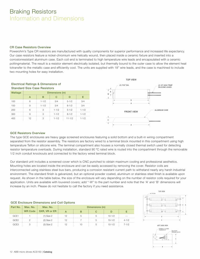
CR Case Resistors Overview
Powerohm’s Type CR resistors are manufactured with quality components for superior performance and increased life expectancy.
Our case resistors feature a nickel-chromium wire helically wound, then placed inside a ceramic fixture and inserted into a
corrosionresistant aluminum case. Each coil end is terminated to high temperature wire leads and encapsulated with a ceramic
pottingmaterial. The result is a resistor element electrically isolated, but thermally bound to the outer case to allow the element heat
totransfer to the metallic case and efficiently cool. The units are supplied with 18” wire leads, and the case is machined to include
two mounting holes for easy installation.
GCE Resistors Overview
The type GCE enclosures are heavy gage screened enclosures featuring a solid bottom and a built-in wiring compartment
separated from the resistor assembly. The resistors are factory wired to a terminal block mounted in this compartment using high
temperature Teflon or silicone wire. The terminal compartment also houses a normally closed thermal switch used for detecting
resistor temperature overloads. During installation, standard 90 ºC rated wire is routed into the compartment through the removable
1/2 inch conduit knockouts and connected to the factory wired terminal block.
Our standard unit includes a screened cover which is CNC punched to obtain maximum cooling and professional aesthetics.
Mounting holes are located inside the enclosure and can be easily accessed by removing the cover. Resistor coils are
interconnected using stainless steel bus bars, producing a corrosion resistant current path to withstand nearly any harsh industrial
environment. The standard finish is galvanized, but an optional powder coated, aluminum or stainless steel finish is available upon
request. As shown in the table below, the size of the enclosure will vary depending on the number of resistor coils required for your
application. Units are available with louvered covers; add “-W” to the part number and note that the ‘A’ and ‘B’ dimensions will
increase by an inch. Please do not hesitate to call the factory if you need assistance.
Braking Resistors
Information and Dimensions
Electrical Ratings & Dimensions of
Standard Size Case Resistors
Wattage Dimensions (in)
A B C D E
100 6 1-1/2 3/4 5-1/2 3/4
150 9 1-1/2 3/4 8-1/2 3/4
200 6 3 1-1/2 5-1/2 1-1/2
300 9 3 1-1/2 8-1/2 1-1/2
400 12 3 1-1/2 11-1/2 1-1/2
B
C
D
A
E
(2) 18" HIGH TEMPSILICONE LEADS
(2) 7/32" DIA.
TOP VIEW
FRONT VIEWALUMINUM CASE
A
GCE Enclosure Dimensions and Coil Options
Part No. Max. No.
WR Code
Max. No.
SXR, VR or ER
Dimensions (in)
A B C D E
GCE1 1 (1) Size 2 12 5 5 10-1/2 ---
GCE2 2 (2) Size 2 12 7 5 10-1/2 4-1/2
GCE3 3 (3) Size 2 12 10 5 10-1/2 7-1/2
C
B
B
A
D
E
NORMALLY CLOSEDTHERMOSTAT
TWO POINTTERMINAL BLOCK
(4) 7/16 DIA.
TOP VIEW
LEFT SIDE VIEW
Catalog | ABB micro drives ACS150 13
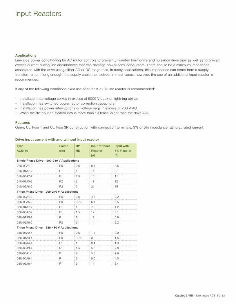
Applications
Line side power conditioning for AC motor controls to prevent unwanted harmonics and nuisance drive trips as well as to prevent
excess current during line disturbances that can damage power semi-conductors. There should be a minimum impedance
associated with the drive using either AC or DC magnetics. In many applications, this impedance can come from a supply
transformer, or if long enough, the supply cable themselves. In most cases, however, the use of an additional input reactor is
recommended.
If any of the following conditions exist use of at least a 3% line reactor is recommended:
– Installation has voltage spikes in excess of 6000 V peak or lightning strikes.
– Installation has switched power factor correction capacitors.
– Installation has power interruptions or voltage sags in excess of 200 V AC.
– When the distribution system kVA is more than 10 times larger than the drive kVA.
Features
Open, UL Type 1 and UL Type 3R construction with connection terminals. 3% or 5% impedance rating at rated current.
Input Reactors
Type
ACS150
Frame
size
HP
ND
Input without
Reactor
[A]
Input with
5% Reactor
[A]
Single Phase Drive - 200-240 V Applications
01U-02A4-2 R0 0.5 6.1 4.5
01U-04A7-2 R1 1 11 8.1
01U-06A7-2 R1 1.5 16 11
01U-07A5-2 R2 2 17 12
01U-09A8-2 R2 3 21 15
Three Phase Drive - 200-240 V Applications
03U-02A4-2 R0 0.5 4.3 2.2
03U-03A5-2 R0 0.75 6.1 3.5
03U-04A7-2 R1 1 7.6 4.2
03U-06A7-2 R1 1.5 12 6.1
03U-07A5-2 R1 2 12 6.9
03U-09A8-2 R2 3 14 9.2
Three Phase Drive - 380-480 V Applications
03U-01A2-4 R0 0.5 1.8 0.9
03U-01A9-4 R0 0.75 3.0 1.5
03U-02A4-4 R1 1 3.4 1.9
03U-03A3-4 R1 1.5 5.0 2.6
03U-04A1-4 R1 2 5.8 2.9
03U-05A6-4 R1 3 8.0 4.0
03U-08A8-4 R1 5 11 6.4
Drive input current with and without input reactor
14 ABB micro drives ACS150 | Catalog
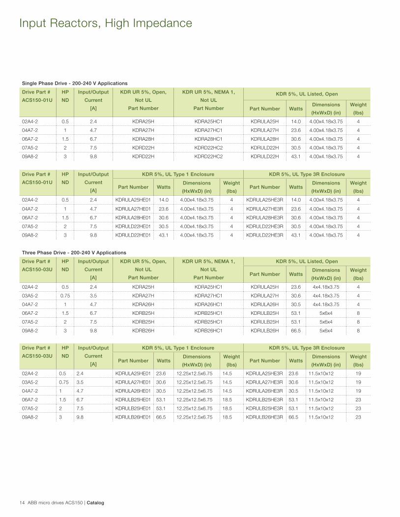
Input Reactors, High Impedance
Single Phase Drive - 200-240 V Applications
Drive Part #
ACS150-01U
HP
ND
Input/Output
Current
[A]
KDR UR 5%, Open,
Not UL
Part Number
KDR UR 5%, NEMA 1,
Not UL
Part Number
KDR 5%, UL Listed, Open
Part Number WattsDimensions
(HxWxD) (in)
Weight
(lbs)
02A4-2 0.5 2.4 KDRA25H KDRA25HC1 KDRULA25H 14.0 4.00x4.18x3.75 4
04A7-2 1 4.7 KDRA27H KDRA27HC1 KDRULA27H 23.6 4.00x4.18x3.75 4
06A7-2 1.5 6.7 KDRA28H KDRA28HC1 KDRULA28H 30.6 4.00x4.18x3.75 4
07A5-2 2 7.5 KDRD22H KDRD22HC2 KDRULD22H 30.5 4.00x4.18x3.75 4
09A8-2 3 9.8 KDRD22H KDRD22HC2 KDRULD22H 43.1 4.00x4.18x3.75 4
Drive Part #
ACS150-01U
HP
ND
Input/Output
Current
[A]
KDR 5%, UL Type 1 Enclosure KDR 5%, UL Type 3R Enclosure
Part Number WattsDimensions
(HxWxD) (in)
Weight
(lbs)Part Number Watts
Dimensions
(HxWxD) (in)
Weight
(lbs)
02A4-2 0.5 2.4 KDRULA25HE01 14.0 4.00x4.18x3.75 4 KDRULA25HE3R 14.0 4.00x4.18x3.75 4
04A7-2 1 4.7 KDRULA27HE01 23.6 4.00x4.18x3.75 4 KDRULA27HE3R 23.6 4.00x4.18x3.75 4
06A7-2 1.5 6.7 KDRULA28HE01 30.6 4.00x4.18x3.75 4 KDRULA28HE3R 30.6 4.00x4.18x3.75 4
07A5-2 2 7.5 KDRULD22HE01 30.5 4.00x4.18x3.75 4 KDRULD22HE3R 30.5 4.00x4.18x3.75 4
09A8-2 3 9.8 KDRULD22HE01 43.1 4.00x4.18x3.75 4 KDRULD22HE3R 43.1 4.00x4.18x3.75 4
Three Phase Drive - 200-240 V Applications
Drive Part #
ACS150-03U
HP
ND
Input/Output
Current
[A]
KDR UR 5%, Open,
Not UL
Part Number
KDR UR 5%, NEMA 1,
Not UL
Part Number
KDR 5%, UL Listed, Open
Part Number WattsDimensions
(HxWxD) (in)
Weight
(lbs)
02A4-2 0.5 2.4 KDRA25H KDRA25HC1 KDRULA25H 23.6 4x4.18x3.75 4
03A5-2 0.75 3.5 KDRA27H KDRA27HC1 KDRULA27H 30.6 4x4.18x3.75 4
04A7-2 1 4.7 KDRA26H KDRA26HC1 KDRULA26H 30.5 4x4.18x3.75 4
06A7-2 1.5 6.7 KDRB25H KDRB25HC1 KDRULB25H 53.1 5x6x4 8
07A5-2 2 7.5 KDRB25H KDRB25HC1 KDRULB25H 53.1 5x6x4 8
09A8-2 3 9.8 KDRB26H KDRB26HC1 KDRULB26H 66.5 5x6x4 8
Drive Part #
ACS150-03U
HP
ND
Input/Output
Current
[A]
KDR 5%, UL Type 1 Enclosure KDR 5%, UL Type 3R Enclosure
Part Number WattsDimensions
(HxWxD) (in)
Weight
(lbs)Part Number Watts
Dimensions
(HxWxD) (in)
Weight
(lbs)
02A4-2 0.5 2.4 KDRULA25HE01 23.6 12.25x12.5x6.75 14.5 KDRULA25HE3R 23.6 11.5x10x12 19
03A5-2 0.75 3.5 KDRULA27HE01 30.6 12.25x12.5x6.75 14.5 KDRULA27HE3R 30.6 11.5x10x12 19
04A7-2 1 4.7 KDRULA26HE01 30.5 12.25x12.5x6.75 14.5 KDRULA26HE3R 30.5 11.5x10x12 19
06A7-2 1.5 6.7 KDRULB25HE01 53.1 12.25x12.5x6.75 18.5 KDRULB25HE3R 53.1 11.5x10x12 23
07A5-2 2 7.5 KDRULB25HE01 53.1 12.25x12.5x6.75 18.5 KDRULB25HE3R 53.1 11.5x10x12 23
09A8-2 3 9.8 KDRULB26HE01 66.5 12.25x12.5x6.75 18.5 KDRULB26HE3R 66.5 11.5x10x12 23
Catalog | ABB micro drives ACS150 15
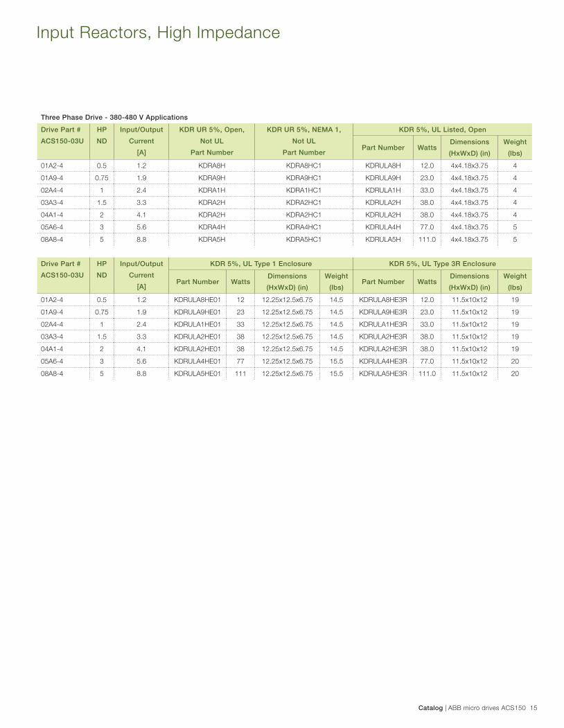
Input Reactors, High Impedance
Three Phase Drive - 380-480 V Applications
Drive Part #
ACS150-03U
HP
ND
Input/Output
Current
[A]
KDR UR 5%, Open,
Not UL
Part Number
KDR UR 5%, NEMA 1,
Not UL
Part Number
KDR 5%, UL Listed, Open
Part Number WattsDimensions
(HxWxD) (in)
Weight
(lbs)
01A2-4 0.5 1.2 KDRA8H KDRA8HC1 KDRULA8H 12.0 4x4.18x3.75 4
01A9-4 0.75 1.9 KDRA9H KDRA9HC1 KDRULA9H 23.0 4x4.18x3.75 4
02A4-4 1 2.4 KDRA1H KDRA1HC1 KDRULA1H 33.0 4x4.18x3.75 4
03A3-4 1.5 3.3 KDRA2H KDRA2HC1 KDRULA2H 38.0 4x4.18x3.75 4
04A1-4 2 4.1 KDRA2H KDRA2HC1 KDRULA2H 38.0 4x4.18x3.75 4
05A6-4 3 5.6 KDRA4H KDRA4HC1 KDRULA4H 77.0 4x4.18x3.75 5
08A8-4 5 8.8 KDRA5H KDRA5HC1 KDRULA5H 111.0 4x4.18x3.75 5
Drive Part #
ACS150-03U
HP
ND
Input/Output
Current
[A]
KDR 5%, UL Type 1 Enclosure KDR 5%, UL Type 3R Enclosure
Part Number WattsDimensions
(HxWxD) (in)
Weight
(lbs)Part Number Watts
Dimensions
(HxWxD) (in)
Weight
(lbs)
01A2-4 0.5 1.2 KDRULA8HE01 12 12.25x12.5x6.75 14.5 KDRULA8HE3R 12.0 11.5x10x12 19
01A9-4 0.75 1.9 KDRULA9HE01 23 12.25x12.5x6.75 14.5 KDRULA9HE3R 23.0 11.5x10x12 19
02A4-4 1 2.4 KDRULA1HE01 33 12.25x12.5x6.75 14.5 KDRULA1HE3R 33.0 11.5x10x12 19
03A3-4 1.5 3.3 KDRULA2HE01 38 12.25x12.5x6.75 14.5 KDRULA2HE3R 38.0 11.5x10x12 19
04A1-4 2 4.1 KDRULA2HE01 38 12.25x12.5x6.75 14.5 KDRULA2HE3R 38.0 11.5x10x12 19
05A6-4 3 5.6 KDRULA4HE01 77 12.25x12.5x6.75 15.5 KDRULA4HE3R 77.0 11.5x10x12 20
08A8-4 5 8.8 KDRULA5HE01 111 12.25x12.5x6.75 15.5 KDRULA5HE3R 111.0 11.5x10x12 20
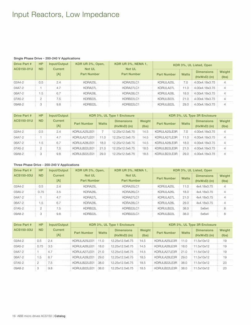
16 ABB micro drives ACS150 | Catalog
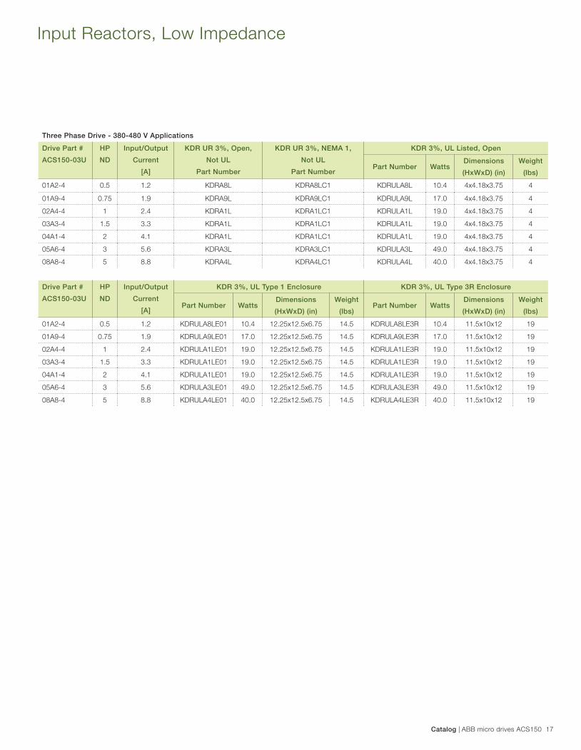
Input Reactors, Low Impedance
Single Phase Drive - 200-240 V Applications
Drive Part #
ACS150-01U
HP
ND
Input/Output
Current
[A]
KDR UR 3%, Open,
Not UL
Part Number
KDR UR 3%, NEMA 1,
Not UL
Part Number
KDR 3%, UL Listed, Open
Part Number WattsDimensions
(HxWxD) (in)
Weight
(lbs)
02A4-2 0.5 2.4 KDRA25L KDRA25LC1 KDRULA25L 7.0 4.00x4.18x3.75 4
04A7-2 1 4.7 KDRA27L KDRA27LC1 KDRULA27L 11.0 4.00x4.18x3.75 4
06A7-2 1.5 6.7 KDRA28L KDRA28LC1 KDRULA28L 18.0 4.00x4.18x3.75 4
07A5-2 2 7.5 KDRB22L KDRB22LC1 KDRULB22L 21.0 4.00x4.18x3.75 4
09A8-2 3 9.8 KDRB22L KDRB22LC1 KDRULB22L 29.0 4.00x4.18x3.75 4
Drive Part #
ACS150-01U
HP
ND
Input/Output
Current
[A]
KDR 3%, UL Type 1 Enclosure KDR 3%, UL Type 3R Enclosure
Part Number WattsDimensions
(HxWxD) (in)
Weight
(lbs)Part Number Watts
Dimensions
(HxWxD) (in)
Weight
(lbs)
02A4-2 0.5 2.4 KDRULA25LE01 7 12.25x12.5x6.75 14.5 KDRULA25LE3R 7.0 4.00x4.18x3.75 4
04A7-2 1 4.7 KDRULA27LE01 11.0 12.25x12.5x6.75 14.5 KDRULA27LE3R 11.0 4.00x4.18x3.75 4
06A7-2 1.5 6.7 KDRULA28LE01 18.0 12.25x12.5x6.75 14.5 KDRULA28LE3R 18.0 4.00x4.18x3.75 4
07A5-2 2 7,5 KDRULB22LE01 21.0 12.25x12.5x6.75 18.5 KDRULB22LE3R 21.0 4.00x4.18x3.75 4
09A8-2 3 9.8 KDRULB22LE01 29.0 12.25x12.5x6.75 18.5 KDRULB22LE3R 29.0 4.00x4.18x3.75 4
Three Phase Drive - 200-240 V Applications
Drive Part #
ACS150-03U
HP
ND
Input/Output
Current
[A]
KDR UR 3%, Open,
Not UL
Part Number
KDR UR 3%, NEMA 1,
Not UL
Part Number
KDR 3%, UL Listed, Open
Part Number WattsDimensions
(HxWxD) (in)
Weight
(lbs)
02A4-2 0.5 2.4 KDRA25L KDRA25LC1 KDRULA25L 11.0 4x4.18x3.75 4
03A5-2 0.75 3.5 KDRA26L KDRA26LC1 KDRULA26L 18.0 4x4.18x3.75 4
04A7-2 1 4.7 KDRA27L KDRA27LC1 KDRULA27L 21.0 4x4.18x3.75 4
06A7-2 1,5 6.7 KDRA28L KDRA28LC1 KDRULA28L 29.0 4x4.18x3.75 4
07A5-2 2 7.5 KDRB22L KDRB22LC1 KDRULB22L 38.0 5x6x4 8
09A8-2 3 9.8 KDRB22L KDRB22LC1 KDRULB22L 38.0 5x6x4 8
Drive Part #
ACS150-03U
HP
ND
Input/Output
Current
[A]
KDR 3%, UL Type 1 Enclosure KDR 3%, UL Type 3R Enclosure
Part Number WattsDimensions
(HxWxD) (in)
Weight
(lbs)Part Number Watts
Dimensions
(HxWxD) (in)
Weight
(lbs)
02A4-2 0.5 2.4 KDRULA25LE01 11.0 12.25x12.5x6.75 14.5 KDRULA25LE3R 11.0 11.5x10x12 19
03A5-2 0.75 3.5 KDRULA26LE01 18.0 12.25x12.5x6.75 14.5 KDRULA26LE3R 18.0 11.5x10x12 19
04A7-2 1 4.7 KDRULA27LE01 21.0 12.25x12.5x6.75 14.5 KDRULA27LE3R 21.0 11.5x10x12 19
06A7-2 1.5 6.7 KDRULA28LE01 29.0 12.25x12.5x6.75 18.5 KDRULA28LE3R 29.0 11.5x10x12 19
07A5-2 2 7.5 KDRULB22LE01 38.0 12.25x12.5x6.75 18.5 KDRULB22LE3R 38.0 11.5x10x12 23
09A8-2 3 9.8 KDRULB22LE01 38.0 12.25x12.5x6.75 18.5 KDRULB22LE3R 38.0 11.5x10x12 23
Catalog | ABB micro drives ACS150 17
Three Phase Drive - 380-480 V Applications
Drive Part #
ACS150-03U
HP
ND
Input/Output
Current
[A]
KDR UR 3%, Open,
Not UL
Part Number
KDR UR 3%, NEMA 1,
Not UL
Part Number
KDR 3%, UL Listed, Open
Part Number WattsDimensions
(HxWxD) (in)
Weight
(lbs)
01A2-4 0.5 1.2 KDRA8L KDRA8LC1 KDRULA8L 10.4 4x4.18x3.75 4
01A9-4 0.75 1.9 KDRA9L KDRA9LC1 KDRULA9L 17.0 4x4.18x3.75 4
02A4-4 1 2.4 KDRA1L KDRA1LC1 KDRULA1L 19.0 4x4.18x3.75 4
03A3-4 1.5 3.3 KDRA1L KDRA1LC1 KDRULA1L 19.0 4x4.18x3.75 4
04A1-4 2 4.1 KDRA1L KDRA1LC1 KDRULA1L 19.0 4x4.18x3.75 4
05A6-4 3 5.6 KDRA3L KDRA3LC1 KDRULA3L 49.0 4x4.18x3.75 4
08A8-4 5 8.8 KDRA4L KDRA4LC1 KDRULA4L 40.0 4x4.18x3.75 4
Drive Part #
ACS150-03U
HP
ND
Input/Output
Current
[A]
KDR 3%, UL Type 1 Enclosure KDR 3%, UL Type 3R Enclosure
Part Number WattsDimensions
(HxWxD) (in)
Weight
(lbs)Part Number Watts
Dimensions
(HxWxD) (in)
Weight
(lbs)
01A2-4 0.5 1.2 KDRULA8LE01 10.4 12.25x12.5x6.75 14.5 KDRULA8LE3R 10.4 11.5x10x12 19
01A9-4 0.75 1.9 KDRULA9LE01 17.0 12.25x12.5x6.75 14.5 KDRULA9LE3R 17.0 11.5x10x12 19
02A4-4 1 2.4 KDRULA1LE01 19.0 12.25x12.5x6.75 14.5 KDRULA1LE3R 19.0 11.5x10x12 19
03A3-4 1.5 3.3 KDRULA1LE01 19.0 12.25x12.5x6.75 14.5 KDRULA1LE3R 19.0 11.5x10x12 19
04A1-4 2 4.1 KDRULA1LE01 19.0 12.25x12.5x6.75 14.5 KDRULA1LE3R 19.0 11.5x10x12 19
05A6-4 3 5.6 KDRULA3LE01 49.0 12.25x12.5x6.75 14.5 KDRULA3LE3R 49.0 11.5x10x12 19
08A8-4 5 8.8 KDRULA4LE01 40.0 12.25x12.5x6.75 14.5 KDRULA4LE3R 40.0 11.5x10x12 19
Input Reactors, Low Impedance
18 ABB micro drives ACS150 | Catalog
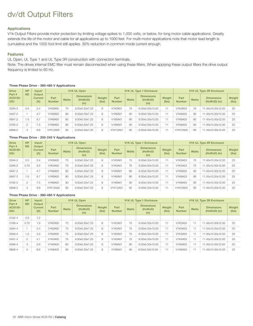
Applications
V1k Output Filters provide motor protection by limiting voltage spikes to 1,000 volts, or below, for long motor cable applications. Greatly
extends the life of the motor and cable for all applications up to 1000 feet. For multi-motor applications note that motor lead length is
cumulative and the 1000 foot limit still applies. 30% reduction in common mode current enough.
Features
UL Open, UL Type 1 and UL Type 3R construction with connection terminals.
Note: The drives internal EMC fi lter must remain disconnected when using these fi lters. When applying these output fi lters the drive output
frequency is limited to 60 Hz.
dv/dt Output Filters
Three Phase Drive - 380-480 V Applications
Drive
Part #
ACS150-
03U
HP
ND
Input/
Output
Current
[A]
V1K UL Open V1K UL Type 1 Enclosure V1K UL Type 3R Enclosure
Part
NumberWatts
Dimensions
(HxWxD)
(in)
Weight
(lbs)
Part
NumberWatts
Dimensions
(HxWxD)
(in)
Weight
(lbs)
Part
NumberWatts
Dimensions
(HxWxD) (in)
Weight
(lbs)
02A4-2 0.5 2.4 V1K3A00 75 9.00x5.50x7.25 8 V1K3A01 75 9.00x5.50x10.00 11 V1K3A03 75 11.45x10.00x12.00 25
04A7-2 1 4.7 V1K6A00 80 9.00x5.50x7.25 8 V1K6A01 80 9.00x5.50x10.00 11 V1K6A03 80 11.45x10.00x12.00 25
06A7-2 1.5 6.7 V1K6A00 80 9.00x5.50x7.25 8 V1K6A01 80 9.00x5.50x10.00 11 V1K6A03 80 11.45x10.00x12.00 25
07A5-2 2 7.5 V1K8A00 90 9.00x5.50x7.25 8 V1K8A01 90 9.00x5.50x10.00 11 V1K8A03 90 11.45x10.00x12.00 25
09A8-2 3 9.8 V1K12A00 95 9.00x5.50x7.25 8 V1K12A01 95 9.00x5.50x10.00 11 V1K12A03 95 11.45x10.00x12.00 25
Three Phase Drive - 200-240 V Applications
Drive
Part #
ACS150-
03U
HP
ND
Input/
Output
Current
[A]
V1K UL Open V1K UL Type 1 Enclosure V1K UL Type 3R Enclosure
Part
NumberWatts
Dimensions
(HxWxD)
(in)
Weight
(lbs)
Part
NumberWatts
Dimensions
(HxWxD)
(in)
Weight
(lbs)
Part
NumberWatts
Dimensions
(HxWxD) (in)
Weight
(lbs)
02A4-2 0.5 2.4 V1K3A00 75 9.00x5.50x7.25 8 V1K3A01 75 9.00x5.50x10.00 11 V1K3A03 75 11.45x10.00x12.00 25
03A5-2 0.75 3.5 V1K4A00 75 9.00x5.50x7.25 8 V1K4A01 75 9.00x5.50x10.00 11 V1K4A03 75 11.45x10.00x12.00 25
04A7-2 1 4.7 V1K6A00 80 9.00x5.50x7.25 8 V1K6A01 80 9.00x5.50x10.00 11 V1K6A03 80 11.45x10.00x12.00 25
06A7-2 1.5 6.7 V1K6A00 80 9.00x5.50x7.25 8 V1K6A01 80 9.00x5.50x10.00 11 V1K6A03 80 11.45x10.00x12.00 25
07A5-2 2 7.5 V1K8A00 90 9.00x5.50x7.25 8 V1K8A01 90 9.00x5.50x10.00 11 V1K8A03 90 11.45x10.00x12.00 25
09A8-2 3 9.8 V1K12A00 95 9.00x5.50x7.25 8 V1K12A01 95 9.00x5.50x10.00 11 V1K12A03 95 11.45x10.00x12.00 25
Three Phase Drive - 380-480 V Applications
Drive
Part #
ACS150-
03U
HP
ND
Input/
Output
Current
[A]
V1K UL Open V1K UL Type 1 Enclosure V1K UL Type 3R Enclosure
Part
NumberWatts
Dimensions
(HxWxD)
(in)
Weight
(lbs)
Part
NumberWatts
Dimensions
(HxWxD)
(in)
Weight
(lbs)
Part
NumberWatts
Dimensions
(HxWxD) (in)
Weight
(lbs)
01A2-4 0.5 1.2
01A9-4 0.75 1.9 V1K2A00 75 9.00x5.50x7.25 8 V1K2A01 75 9.00x5.50x10.00 11 V1K2A03 11 11.45x10.00x12.00 25
02A4-4 1 2.4 V1K3A00 75 9.00x5.50x7.25 8 V1K3A01 75 9.00x5.50x10.00 11 V1K3A03 11 11.45x10.00x12.00 25
03A3-4 1.5 3.3 V1K3A00 75 9.00x5.50x7.25 8 V1K3A01 75 9.00x5.50x10.00 11 V1K3A03 11 11.45x10.00x12.00 25
04A1-4 2 4.1 V1K4A00 75 9.00x5.50x7.25 8 V1K4A01 75 9.00x5.50x10.00 11 V1K4A03 11 11.45x10.00x12.00 25
05A6-4 3 5.6 V1K6A00 80 9.00x5.50x7.25 8 V1K6A01 80 9.00x5.50x10.00 11 V1K6A03 11 11.45x10.00x12.00 25
08A8-4 5 8.8 V1K8A00 90 9.00x5.50x7.25 8 V1K8A01 90 9.00x5.50x10.00 11 V1K8A03 11 11.45x10.00x12.00 25
Catalog | ABB micro drives ACS150 19
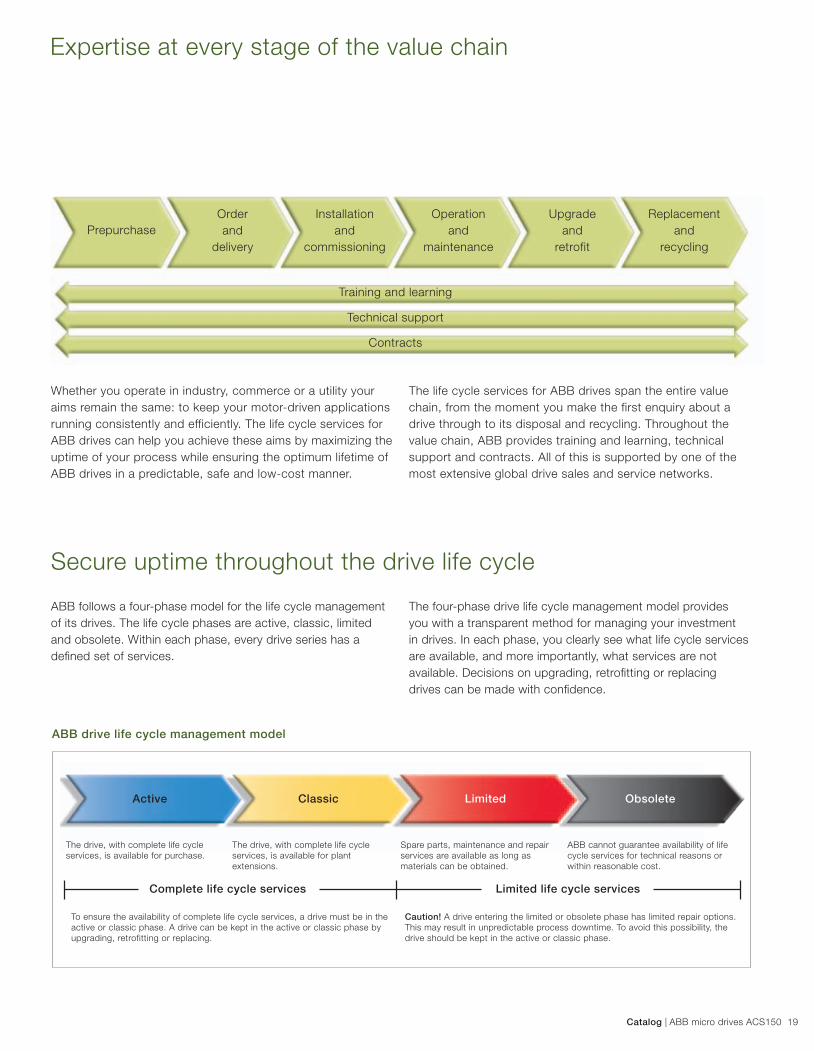
Expertise at every stage of the value chain
Secure uptime throughout the drive life cycle
Whether you operate in industry, commerce or a utility your
aims remain the same: to keep your motor-driven applications
running consistently and efficiently. The life cycle services for
ABB drives can help you achieve these aims by maximizing the
uptime of your process while ensuring the optimum lifetime of
ABB drives in a predictable, safe and low-cost manner.
ABB follows a four-phase model for the life cycle management
of its drives. The life cycle phases are active, classic, limited
and obsolete. Within each phase, every drive series has a
defi ned set of services.
ABB drive life cycle management model
Prepurchase
Order
and
delivery
Installation
and
commissioning
Operation
and
maintenance
Upgrade
and
retrofit
Replacement
and
recycling
Training and learning
Technical support
Contracts
The life cycle services for ABB drives span the entire value
chain, from the moment you make the first enquiry about a
drive through to its disposal and recycling. Throughout the
value chain, ABB provides training and learning, technical
support and contracts. All of this is supported by one of the
most extensive global drive sales and service networks.
The four-phase drive life cycle management model provides
you with a transparent method for managing your investment
in drives. In each phase, you clearly see what life cycle services
are available, and more importantly, what services are not
available. Decisions on upgrading, retrofi tting or replacing
drives can be made with confi dence.
The drive, with complete life cycle
services, is available for purchase.
The drive, with complete life cycle
services, is available for plant
extensions.
Spare parts, maintenance and repair
services are available as long as
materials can be obtained.
ABB cannot guarantee availability of life
cycle services for technical reasons or
within reasonable cost.
Complete life cycle services Limited life cycle services
To ensure the availability of complete life cycle services, a drive must be in the
active or classic phase. A drive can be kept in the active or classic phase by
upgrading, retrofitting or replacing.
Caution! A drive entering the limited or obsolete phase has limited repair options.
This may result in unpredictable process downtime. To avoid this possibility, the
drive should be kept in the active or classic phase.
Active Classic Limited Obsolete

Contact us
3A
UA
00
00
08
56
31
RE
V F
US
31
.3.2
01
5© Copyright 2015 ABB. All rights reserved.
Specifi cations subject to change without notice.For more information please contact your local ABB
representative or visit:
www.abb.com/drives