low voltage ac drives abb micro drives 0.5 to 20 hp / … voltage ac drives abb micro drives ......
TRANSCRIPT
Low Voltage AC Drives
ABB Micro DrivesACS2550.5 to 20 hp / 0.37 to 15 kWCatalog
2 ABB ACS255 Technical Catalog
Selecting and ordering your drive
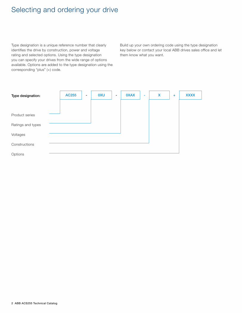
Type designation is a unique reference number that clearlyidentifies the drive by construction, power and voltagerating and selected options. Using the type designationyou can specify your drives from the wide range of optionsavailable. Options are added to the type designation using thecorresponding “plus” (+) code.
Build up your own ordering code using the type designation key below or contact your local ABB drives sales office and let them know what you want.
Type designation:
Product series
Ratings and types
Voltages
Constructions
Options
AC255 - 0XU - 0XAX - X + XXXX
ABB ACS255 Technical Catalog 3
ACS255, micro driveTable of contents
ACS255
Introduction 4
Main features 5
ACS255-IP20
Overview 6
Data sheet 7
Ratings and types 8
Dimensions and weights 9
ACS255-IP66
Overview 10
Data sheet 11
Ratings and types 12
Dimensions and weights 13
Technical data
Cooling 14
Fuses and cable sizes 15
Control connections for 115, 240 and 480 V 16
Control connections for 600 V 17
Options
Options 18
Braking resistors
Single-phase 19
Three-phase 20
Resistor technical data 23
CR case resistor 24
GCE resistor 25
Installation instructions 26
Reactors
Input reactors 27
Output filters 32
Life cycle management
Life cycle management 35
AC255 - 0XU - 0XAX - X + XXXX
4 ABB ACS255 Technical Catalog
Introduction to the ACS255
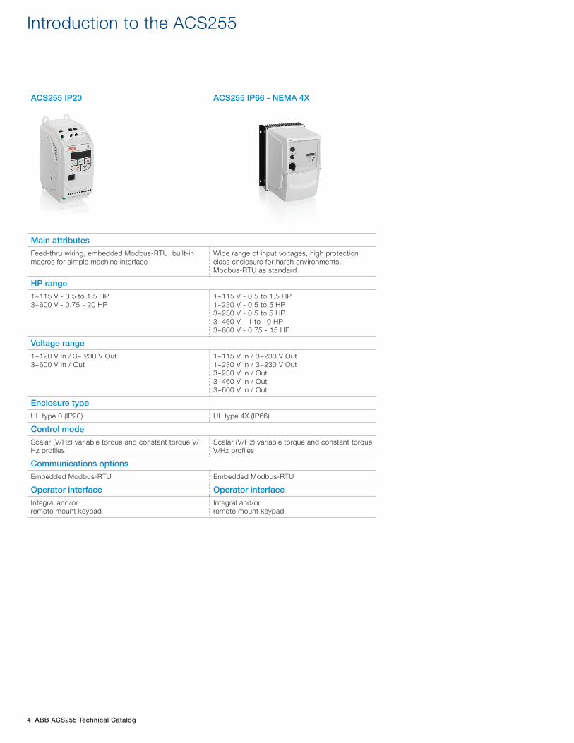
ACS255 IP20 ACS255 IP66 - NEMA 4X
Main attributes
Feed-thru wiring, embedded Modbus-RTU, built-in macros for simple machine interface
Wide range of input voltages, high protection class enclosure for harsh environments, Modbus-RTU as standard
HP range
1~115 V - 0.5 to 1.5 HP3~600 V - 0.75 - 20 HP
1~115 V - 0.5 to 1.5 HP1~230 V - 0.5 to 5 HP3~230 V - 0.5 to 5 HP3~460 V - 1 to 10 HP3~600 V - 0.75 - 15 HP
Voltage range
1~120 V In / 3~ 230 V Out3~600 V In / Out
1~115 V In / 3~230 V Out1~230 V In / 3~230 V Out3~230 V In / Out3~460 V In / Out3~600 V In / Out
Enclosure type
UL type 0 (IP20) UL type 4X (IP66)
Control mode
Scalar (V/Hz) variable torque and constant torque V/Hz profiles
Scalar (V/Hz) variable torque and constant torque V/Hz profiles
Communications options
Embedded Modbus-RTU Embedded Modbus-RTU
Operator interface Operator interface
Integral and/or remote mount keypad
Integral and/or remote mount keypad
ABB ACS255 Technical Catalog 5
Main features
OverviewThe new ACS255 drive is an enhanced verison of the popularACS250 drive series. New features include: sensorless vectorcontrol for both AC induction and PM motors, enhanced shortcircuit protection, and operating mode selection. New ratingshave been added to fill out the product line.
All of the existing features of the ACS250 - parameters, exter-nal dimensions, mounting locations, etc. - are the same for theACS255. An Advanced parameter menu has been added foradditional functionality.
The ACS255 drive is a part of ABB’s complete range of micro drives, offering a solution for every need. The IP20 drives offer 115V and 600V options to enhance other IP20 product lines. The IP66 drives have a complete input voltage range from 115 to 600V.
ACS255 variable frequency drives feature an intuitive integrated control panel with LED display. Built-in macros and only the essential parameters make commissioning straightforward. Built-in Modbus-RTU serial communication provides ready integration with control and monitoring systems.
ACS255 micro drives are compact and offer flexible mounting options without the need for accessory mounting kits. Rapid programming and commissioning are possible using the on board setup macros. The copy stick tool can be used to trans-fer parameter sets between drives.
The ACS255 drive is ideal for panel builders and OEM’s need-ing a micro drive with low cost, flexible mounting options, and rapid parameter setup.
Highlights − Power range: 0.5 to 20 Hp, 1 & 3 phase input − 150% peak overload capacity − Modbus-RTU built-in − User-friendly control panel with LED display − Wall or DIN rail mounting options for IP20 drives − Feed thru wiring on IP20 drives − PI control − Built-in brake chopper (Sizes 2 & 3) − Sensorless vector and V/Hz control - all voltages − Safe Torque Off (STO) (600V drives only) − Conformally coated boards − Operating mode selection − Easy access to power and I/O connections for rapid instal-
lation − Selection options for braking resistors, input reactors, &
output filters
Applications
− Conveyors − Mixers − Material handling − Fans and pumps
− Automated Gate Control − Food and Beverage − Printing − Woodworking Machinery
Feature Advantage Benefit
Simple interface Integrated keypad and display is easy to learn and makes commissioning straightforward ABB common programming parameter structure
Time and labor cost savings with rapid setup and commissioning
Drive & network connectivity
RS485 serial interface with embedded Modbus RTU for real time control (or monitoring) RJ45 connection port can be used with: Optional Y-splitter for daisy chain networking Remote control panel Copy Stick tool for transferring parameters between drives
Flexibility with RJ45 connectivity options Time savings with simple plug-and-play connectivity
IP66 Construction with Optional Controls
Optional operator controls: Disconnect, Fwd/Off/Rev, & Speed Potentiometer Dust and water proof design built with tough ABS plastic cover, epoxy coated heatsink that withstands high pressure washdown for food and beverage applications. Optional operator controls allows mounting directly on processing equipment located in extreme environments
Save panel building cost Less cost due to shorter motor cables with machine mounted drive Operator controls located on the machine
Full voltage range in IP66 drives
IP66 offering throughout the voltage range - 110V to 600V Global input voltage range to cover a wide range of application
Standardize on one supplier with global input voltage range save procurement and inventory cost
Feed Through Wiring & Flexible Mounting Options (IP20 Drives)
Allows for easy replacement of motor starters or soft starters in existing panels with power wires in at the top and motor cables out at the bottom Flexible mounting options - wall or DIN rail
Saves time and material cost for panel builders
600V Ratings in IP20 and IP66 Enclosures
600V capacity in a micro drive with Safe Torque Off (SIL2) Panel design standardization with compact micro drive sizing in a 600V drive - similar to 115, 230, & 460Vmicro drives
ACS255 - 0XU - 0XAX - X
6 ABB ACS255 Technical Catalog
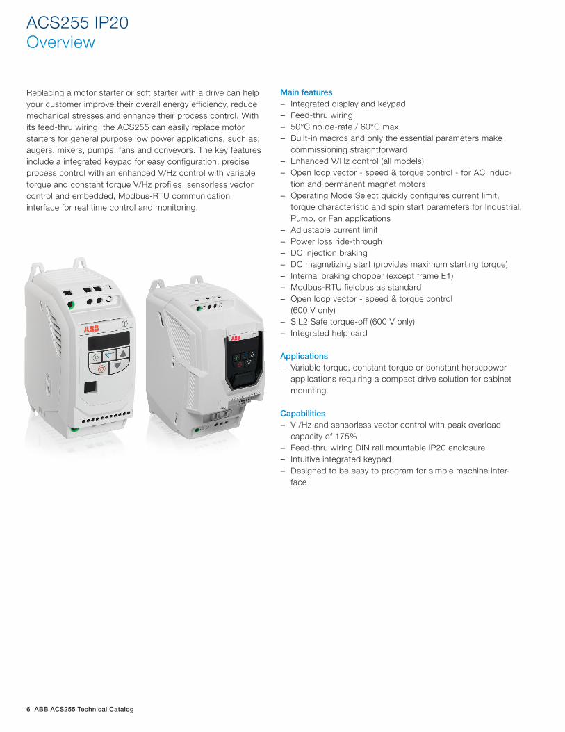
Replacing a motor starter or soft starter with a drive can help your customer improve their overall energy efficiency, reduce mechanical stresses and enhance their process control. With its feed-thru wiring, the ACS255 can easily replace motor starters for general purpose low power applications, such as; augers, mixers, pumps, fans and conveyors. The key features include a integrated keypad for easy configuration, precise process control with an enhanced V/Hz control with variable torque and constant torque V/Hz profiles, sensorless vectorcontrol and embedded, Modbus-RTU communicationinterface for real time control and monitoring.
Main features − Integrated display and keypad − Feed-thru wiring − 50°C no de-rate / 60°C max. − Built-in macros and only the essential parameters make
commissioning straightforward − Enhanced V/Hz control (all models) − Open loop vector - speed & torque control - for AC Induc-
tion and permanent magnet motors − Operating Mode Select quickly configures current limit,
torque characteristic and spin start parameters for Industrial, Pump, or Fan applications
− Adjustable current limit − Power loss ride-through − DC injection braking − DC magnetizing start (provides maximum starting torque) − Internal braking chopper (except frame E1) − Modbus-RTU fieldbus as standard − Open loop vector - speed & torque control
(600 V only) − SIL2 Safe torque-off (600 V only) − Integrated help card
Applications
− Variable torque, constant torque or constant horsepower applications requiring a compact drive solution for cabinet mounting
Capabilities − V /Hz and sensorless vector control with peak overload
capacity of 175% − Feed-thru wiring DIN rail mountable IP20 enclosure − Intuitive integrated keypad − Designed to be easy to program for simple machine inter-
face
ACS255 IP20 Overview

ABB ACS255 Technical Catalog 7
ACS255 IP20Data sheet
0.5 thru 1.5 HP (1~115 V In/ 3~230V Out) 1 thru 20 HP (3~600 V In/Out)
Performance features Control modes 115 VAC: V/Hz and open loop vector 600 VAC: V/Hz and open loop vector
Operator interface module Integral drive mounted
Display lines 6-character LED display
Programmable preset speeds
Four
Analog output: one One (0-10 VDC)
Auto restart Yes – up to 5 attempts
Frequency avoidance One band
Fault history Last four faults
Digital inputs: four Two programmable digital inputs, two user selectable analog/digital inputs
Digital inputs type Pull-upDrive specifications Analog inputs: two 0-10 VDC, 4 to 20mA
Relay output: one Built-in form C relay
Analog output / digital outout
0-10 VDC: one analog usable for meter (freq., current, voltage) or digital output
Overload capacity Drive output 150% for one minute and 175% for 2 seconds
Maximum load 1.5 HP @ 120 V In/230 V Out, 20 HP @ 600 V In/Out
Input voltage ranges 115 VAC (99-126); 600 VAC (450-660)
Rated input frequency 50-60 Hz (±5%)
Carrier frequency 4-32 kHz (8 kHz default)
Operating temperature -10° to 50°C
Snubber (dynamic braking) Built-in transistor (frames 2 and 3)
Dynamic braking external Up to 150% dynamic braking with appropriately sized resistor
DC injection braking Included
Volts/Hz Linear V/Hz, user defined, energy optimizer & boost function
Sensorless vector Speed and torque with autotune for AC induction and permanent magnet motors
Frequency control range 0-500 Hz
Accel/decel: Independently adjustable accel. & decel. ramps
Time range 0.00 to 600.0 Seconds
Keypad speed control Yes
Sink/source inputs Source, 24 VDC logic
Electronic overload trip Electronic motor overload inverse 150% for 1 minute or 175% for 2 seconds
Communications Built-in Modbus-RTU (RS-485) communications
PI control Built-inProtective features Under voltage Level depends on voltage class
Output short circuit Phase-to-phase on drive output
Over temperature Heat sink monitor
DC bus overvoltage DC bus level trip
Drive overload Exceed drive rating of 150% for one minute or 175% for 2 seconds
Over current Over-current/short-circuit protection
Output phase Trips on open output phase
Loss of reference Trips on loss of speed command signal
Communication error Detects a communication error (fault)Agency certifications UL, cUL, CE, C-tick, gostService conditions Altitude 1,000 m (3,300 ft.), derate by 1% per 100M up to 2,000 on maximum
Ambient temperature -10°C (14°F) to 50°C (102°F)
Storage temperature: -40°C (-40°F) to 60°C (140°F)
Relative humidity 10% to 95%, non-condensing
8 ABB ACS255 Technical Catalog
ACS255, IP20 Ratings and types
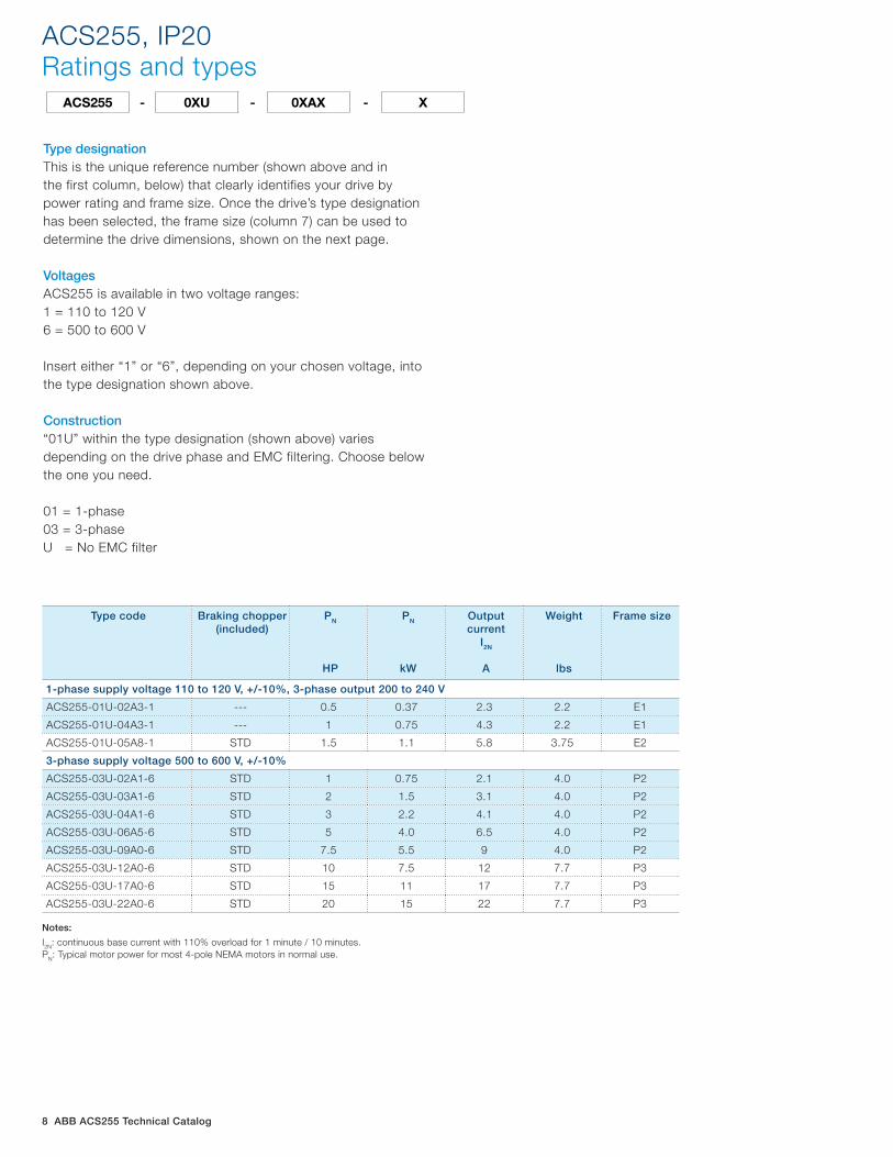
Type designationThis is the unique reference number (shown above and inthe first column, below) that clearly identifies your drive by power rating and frame size. Once the drive’s type designation has been selected, the frame size (column 7) can be used to determine the drive dimensions, shown on the next page.
VoltagesACS255 is available in two voltage ranges:1 = 110 to 120 V6 = 500 to 600 V
Insert either “1” or “6”, depending on your chosen voltage, intothe type designation shown above.
Construction“01U” within the type designation (shown above) variesdepending on the drive phase and EMC filtering. Choose belowthe one you need.
01 = 1-phase03 = 3-phase U = No EMC filter
ACS255 - 0XU - 0XAX - X
Type code Braking chopper (included)
PN
HP
PN
kW
Output current
I2N
A
Weight
lbs
Frame size
1-phase supply voltage 110 to 120 V, +/-10%, 3-phase output 200 to 240 V
ACS255-01U-02A3-1 --- 0.5 0.37 2.3 2.2 E1
ACS255-01U-04A3-1 --- 1 0.75 4.3 2.2 E1
ACS255-01U-05A8-1 STD 1.5 1.1 5.8 3.75 E2
3-phase supply voltage 500 to 600 V, +/-10%
ACS255-03U-02A1-6 STD 1 0.75 2.1 4.0 P2
ACS255-03U-03A1-6 STD 2 1.5 3.1 4.0 P2
ACS255-03U-04A1-6 STD 3 2.2 4.1 4.0 P2
ACS255-03U-06A5-6 STD 5 4.0 6.5 4.0 P2
ACS255-03U-09A0-6 STD 7.5 5.5 9 4.0 P2
ACS255-03U-12A0-6 STD 10 7.5 12 7.7 P3
ACS255-03U-17A0-6 STD 15 11 17 7.7 P3
ACS255-03U-22A0-6 STD 20 15 22 7.7 P3
Notes:
I2N: continuous base current with 110% overload for 1 minute / 10 minutes.PN: Typical motor power for most 4-pole NEMA motors in normal use.
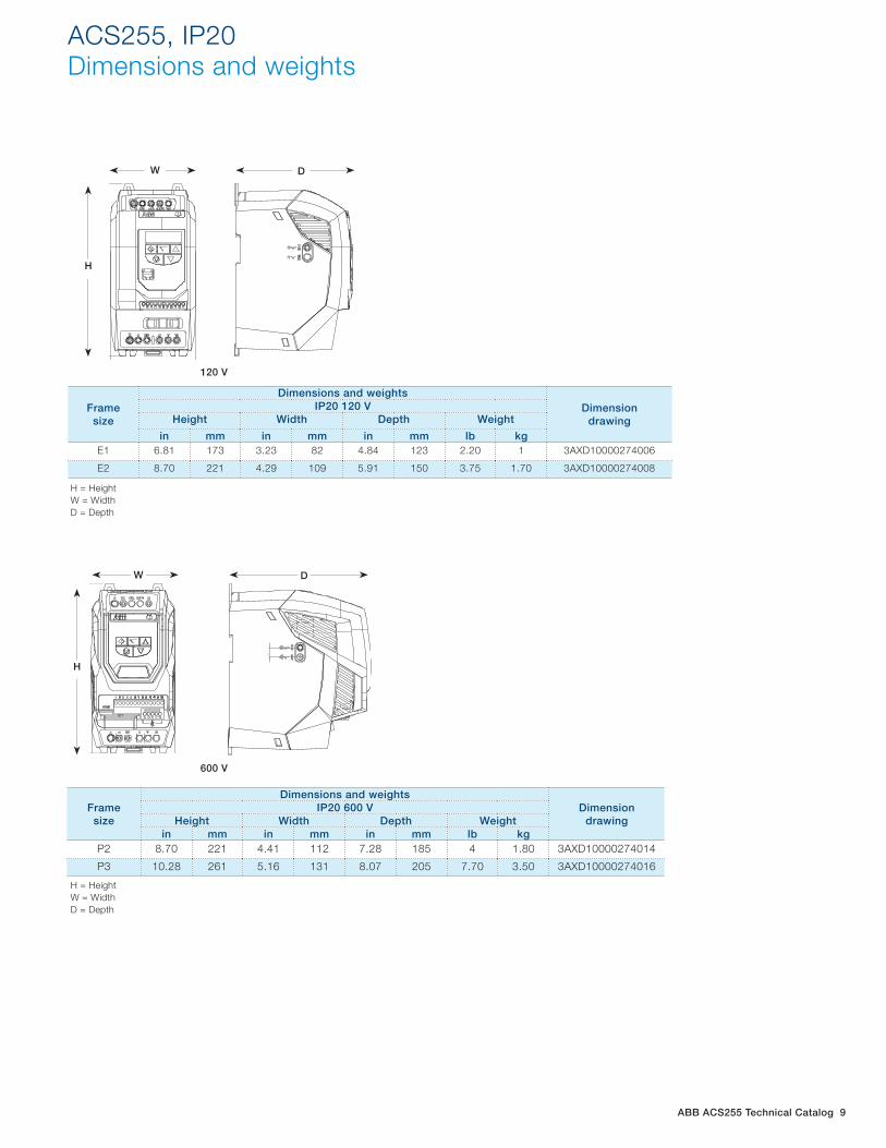
ABB ACS255 Technical Catalog 9
120 V
ACS255, IP20 Dimensions and weights
W D
H
W
H
D
600 V
W D
H
12
H
DW
Frame size
Dimensions and weightsDimension
drawingIP20 120 V
Height Width Depth Weight
in mm in mm in mm lb kgE1 6.81 173 3.23 82 4.84 123 2.20 1 3AXD10000274006
E2 8.70 221 4.29 109 5.91 150 3.75 1.70 3AXD10000274008
Framesize
Dimensions and weightsDimension
drawingIP20 600 V
Height Width Depth Weightin mm in mm in mm lb kg
P2 8.70 221 4.41 112 7.28 185 4 1.80 3AXD10000274014
P3 10.28 261 5.16 131 8.07 205 7.70 3.50 3AXD10000274016
H = HeightW = WidthD = Depth
H = HeightW = WidthD = Depth
12
H
DW
10 ABB ACS255 Technical Catalog
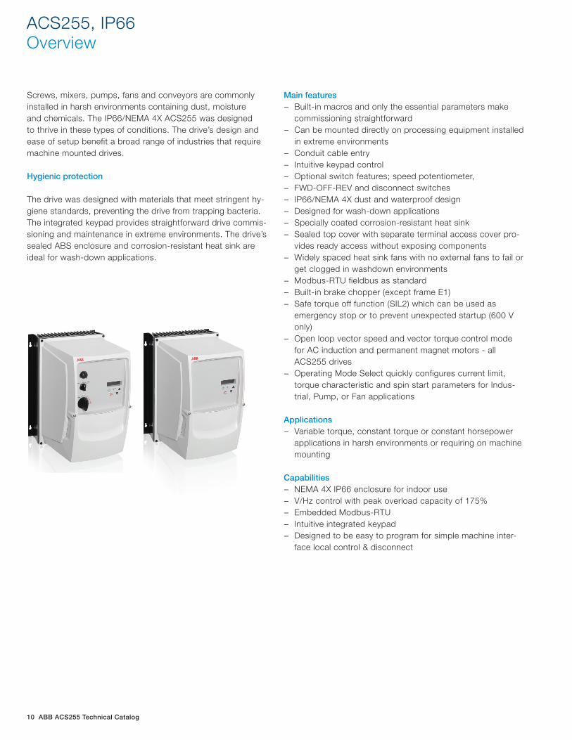
Screws, mixers, pumps, fans and conveyors are commonly installed in harsh environments containing dust, moisture and chemicals. The IP66/NEMA 4X ACS255 was designed to thrive in these types of conditions. The drive’s design and ease of setup benefit a broad range of industries that require machine mounted drives.
Hygienic protection
The drive was designed with materials that meet stringent hy-giene standards, preventing the drive from trapping bacteria. The integrated keypad provides straightforward drive commis-sioning and maintenance in extreme environments. The drive’s sealed ABS enclosure and corrosion-resistant heat sink are ideal for wash-down applications.
Main features − Built-in macros and only the essential parameters make
commissioning straightforward − Can be mounted directly on processing equipment installed
in extreme environments − Conduit cable entry − Intuitive keypad control − Optional switch features; speed potentiometer, − FWD-OFF-REV and disconnect switches − IP66/NEMA 4X dust and waterproof design − Designed for wash-down applications − Specially coated corrosion-resistant heat sink − Sealed top cover with separate terminal access cover pro-
vides ready access without exposing components − Widely spaced heat sink fans with no external fans to fail or
get clogged in washdown environments − Modbus-RTU fieldbus as standard − Built-in brake chopper (except frame E1) − Safe torque off function (SIL2) which can be used as
emergency stop or to prevent unexpected startup (600 V only)
− Open loop vector speed and vector torque control mode for AC induction and permanent magnet motors - all ACS255 drives
− Operating Mode Select quickly configures current limit, torque characteristic and spin start parameters for Indus-trial, Pump, or Fan applications
Applications − Variable torque, constant torque or constant horsepower
applications in harsh environments or requiring on machine mounting
Capabilities − NEMA 4X IP66 enclosure for indoor use − V/Hz control with peak overload capacity of 175% − Embedded Modbus-RTU − Intuitive integrated keypad − Designed to be easy to program for simple machine inter-
face local control & disconnect
ACS255, IP66 Overview
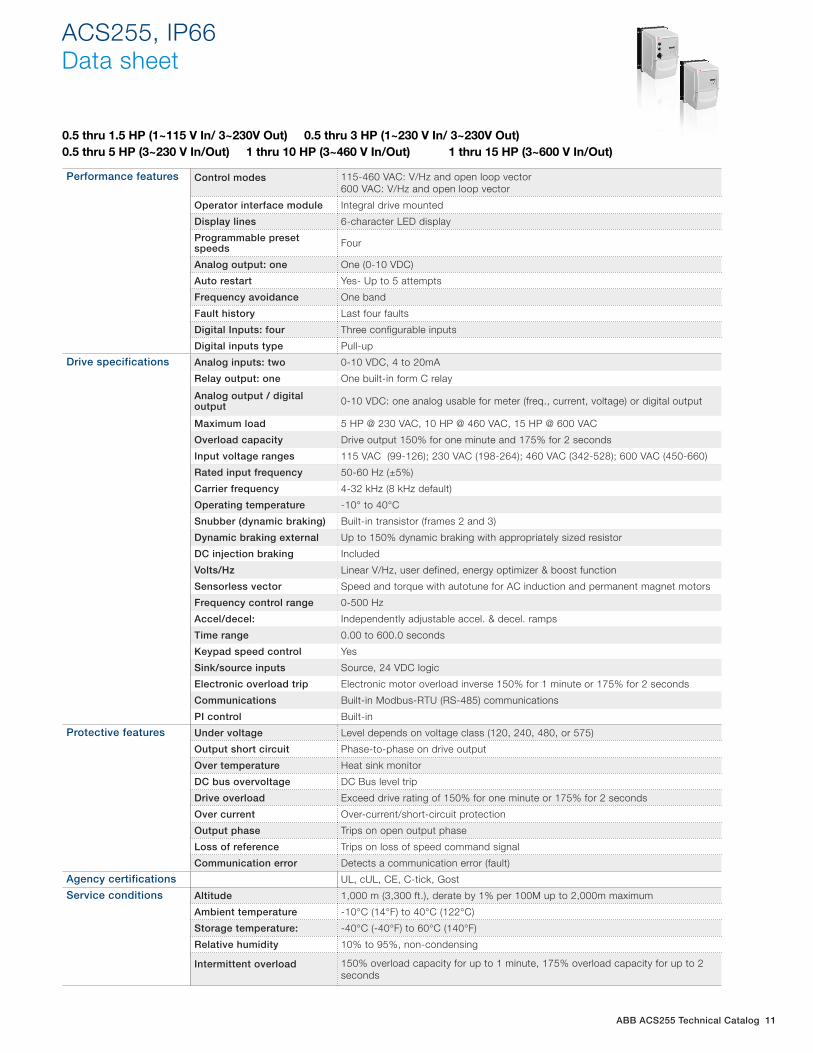
ABB ACS255 Technical Catalog 11
0.5 thru 1.5 HP (1~115 V In/ 3~230V Out) 0.5 thru 3 HP (1~230 V In/ 3~230V Out) 0.5 thru 5 HP (3~230 V In/Out) 1 thru 10 HP (3~460 V In/Out) 1 thru 15 HP (3~600 V In/Out)
ACS255, IP66Data sheet
Performance features Control modes 115-460 VAC: V/Hz and open loop vector600 VAC: V/Hz and open loop vector
Operator interface module Integral drive mounted
Display lines 6-character LED display
Programmable preset speeds Four
Analog output: one One (0-10 VDC)
Auto restart Yes- Up to 5 attempts
Frequency avoidance One band
Fault history Last four faults
Digital Inputs: four Three configurable inputs
Digital inputs type Pull-up
Drive specifications Analog inputs: two 0-10 VDC, 4 to 20mA
Relay output: one One built-in form C relay
Analog output / digital output 0-10 VDC: one analog usable for meter (freq., current, voltage) or digital output
Maximum load 5 HP @ 230 VAC, 10 HP @ 460 VAC, 15 HP @ 600 VAC
Overload capacity Drive output 150% for one minute and 175% for 2 seconds
Input voltage ranges 115 VAC (99-126); 230 VAC (198-264); 460 VAC (342-528); 600 VAC (450-660)
Rated input frequency 50-60 Hz (±5%)
Carrier frequency 4-32 kHz (8 kHz default)
Operating temperature -10° to 40°C
Snubber (dynamic braking) Built-in transistor (frames 2 and 3)
Dynamic braking external Up to 150% dynamic braking with appropriately sized resistor
DC injection braking Included
Volts/Hz Linear V/Hz, user defined, energy optimizer & boost function
Sensorless vector Speed and torque with autotune for AC induction and permanent magnet motors
Frequency control range 0-500 Hz
Accel/decel: Independently adjustable accel. & decel. ramps
Time range 0.00 to 600.0 seconds
Keypad speed control Yes
Sink/source inputs Source, 24 VDC logic
Electronic overload trip Electronic motor overload inverse 150% for 1 minute or 175% for 2 seconds
Communications Built-in Modbus-RTU (RS-485) communications
PI control Built-in
Protective features Under voltage Level depends on voltage class (120, 240, 480, or 575)
Output short circuit Phase-to-phase on drive output
Over temperature Heat sink monitor
DC bus overvoltage DC Bus level trip
Drive overload Exceed drive rating of 150% for one minute or 175% for 2 seconds
Over current Over-current/short-circuit protection
Output phase Trips on open output phase
Loss of reference Trips on loss of speed command signal
Communication error Detects a communication error (fault)
Agency certifications UL, cUL, CE, C-tick, Gost
Service conditions Altitude 1,000 m (3,300 ft.), derate by 1% per 100M up to 2,000m maximum
Ambient temperature -10°C (14°F) to 40°C (122°C)
Storage temperature: -40°C (-40°F) to 60°C (140°F)
Relative humidity 10% to 95%, non-condensing
Intermittent overload 150% overload capacity for up to 1 minute, 175% overload capacity for up to 2 seconds
12 ABB ACS255 Technical Catalog
ACS255, IP66Ratings and types
Type code Braking chopper
(included)
PN
HP
PN
kW
Output current
I2N
A
Weight(lbs)
Frame size
1-phase supply voltage 110 to 120V, +/-10%, 3-phase output 200 to 240 V
ACS255-01U-02A3-1+B063(+F278) - 0.5 0.37 2.3 6.5 E1
ACS255-01U-04A3-1+B063(+F278) - 1.0 0.75 4.3 6.5 E1
ACS255-01U-05A8-1+B063(+F278) X 1.5 1.1 5.8 9.3 E2
1-phase supply voltage 200 to 240V, +/-10%, 3-phase output 200 to 240 V
ACS255-01U-02A3-2+B063(+F278) - 0.5 0.37 2.3 6.5 E1
ACS255-01U-04A3-2+B063(+F278) - 1.0 0.75 4.3 6.5 E1
ACS255-01U-06A1-2+B063(+F278) - 1.5 1.1 6.1 6.5 E1
ACS255-01U-07A0-2+B063(+F278) - 2.0 1.5 7.0 6.5 E1
ACS255-01U-10A5-2+B063(+F278) X 3.0 2.2 10.5 9.3 E2
ACS255-01U-15A3-2+B063(+F278) X 5.0 3.7 15.3 17.0 E3
3-phase supply voltage 200 to 240 V, +/-10%
ACS255-03U-02A3-2+B063(+F278) - 0.5 0.37 2.3 6.5 E1
ACS255-03U-04A3-2+B063(+F278) - 1.0 0.75 4.3 6.5 E1
ACS255-03U-06A1-2+B063(+F278) - 1.5 1.10 6.1 6.5 E1
ACS255-03U-07A0-2+B063(+F278) X 2.0 1.5 7.0 9.3 E2
ACS255-03U-10A5-2+B063(+F278) X 3.0 2.2 10.5 9.3 E2
ACS255-03U-18A0-2+B063(+F278) X 5.0 4.0 18.0 17.0 E3
ACS255-03U-18A0-2+B063+F278 X 5.0 4.0 18.0 17.0 E3
3-phase supply voltage 380 to 480 V, +/-10%
ACS255-03U-01A2-4+B063(+F278) - 0.5 0.37 1.2 6.5 E1
ACS255-03U-02A2-4+B063(+F278) - 1.0 0.75 2.2 6.5 E1
ACS255-03U-03A3-4+B063(+F278) - 1.5 1.1 3.3 6.5 E1
ACS255-03U-04A1-4+B063(+F278) - 2.0 1.5 4.1 6.5 E1
ACS255-03U-05A8-4+B063(+F278) X 3.0 2.2 5.8 9.3 E2
ACS255-03U-09A5-4+B063(+F278) X 5.0 4.0 9.5 9.3 E2
ACS255-03U-14A0-4+B063(+F278) X 7.5 5.5 14.0 17.0 E3
ACS255-03U-18A0-4+B063(+F278) X 10.0 7.5 18.0 17.0 E3
3-phase supply voltage 500 to 600 V, +/-10%
ACS255-03U-02A1-6+B063(+F278) X 1.0 0.75 2.1 10.6 P2
ACS255-03U-03A1-6+B063(+F278) X 2.0 1.5 3.1 10.6 P2
ACS255-03U-04A1-6+B063(+F278) X 3.0 2.2 4.1 10.6 P2
ACS255-03U-06A5-6+B063(+F278) X 5.0 4.0 6.5 10.6 P2
ACS255-03U-09A0-6+B063(+F278) X 7.5 5.5 9.0 10.6 P2
ACS255-03U-12A0-6+B063(+F278) X 10.0 7.5 12.0 16.1 P3
ACS255-03U-17A0-6+B063(+F278) X 15.0 11.0 17.0 16.1 P3
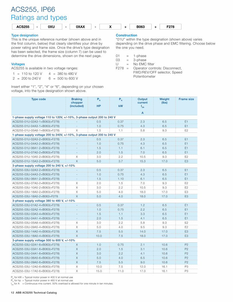
Type designationThis is the unique reference number (shown above and inthe first column, below) that clearly identifies your drive by power rating and frame size. Once the drive’s type designation has been selected, the frame size (column 7) can be used to determine the drive dimensions, shown on the next page.
VoltagesACS255 is available in two voltage ranges:
1 = 110 to 120 V 2 = 200 to 240 V
4 = 380 to 480 V6 = 500 to 600 V
Insert either “1”, “2”, “4” or “6”, depending on your chosen voltage, into the type designation shown above.
Construction“01U” within the type designation (shown above) variesdepending on the drive phase and EMC filtering. Choose belowthe one you need.
01 = 1-phase03 = 3-phase U = No EMC filter F278 = Operator controls: Disconnect, FWD/REV/OFF selector, Speed Potentiometer
ACS255 - 0XU - 0XAX - X + B063 + F278
PN for kW = Typical motor power in 400 V at normal usePN for hp = Typical motor power in 460 V at normal useI2N for A = Continuous rms current. 50% overload is allowed for one minute in ten minutes.
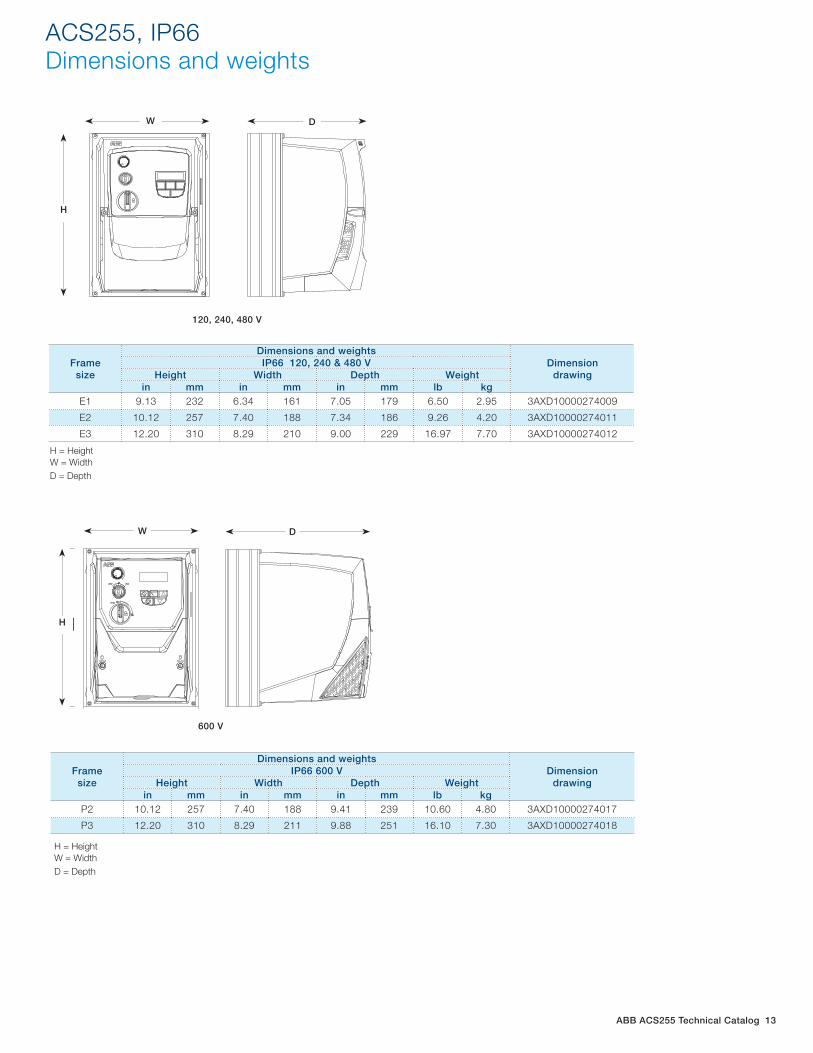
ABB ACS255 Technical Catalog 13
ACS255, IP66 Dimensions and weights
Frame size
Dimensions and weightsDimension
drawingIP66 120, 240 & 480 V
Height Width Depth Weightin mm in mm in mm lb kg
E1 9.13 232 6.34 161 7.05 179 6.50 2.95 3AXD10000274009
E2 10.12 257 7.40 188 7.34 186 9.26 4.20 3AXD10000274011
E3 12.20 310 8.29 210 9.00 229 16.97 7.70 3AXD10000274012
Frame size
Dimensions and weightsDimension
drawingIP66 600 V
Height Width Depth Weightin mm in mm in mm lb kg
P2 10.12 257 7.40 188 9.41 239 10.60 4.80 3AXD10000274017
P3 12.20 310 8.29 211 9.88 251 16.10 7.30 3AXD10000274018
H = HeightW = WidthD = Depth
H = HeightW = WidthD = Depth
W
H
D120, 240, 480 V
W D
H
H
W D600 V
W D
HH
W D
14 ABB ACS255 Technical Catalog
Cooling
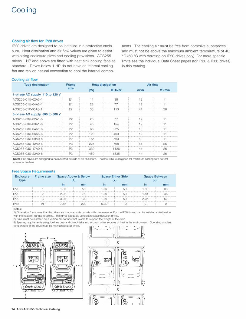
Cooling air fl ow for IP20 drivesIP20 drives are designed to be installed in a protective enclo-sure. Heat dissipation and air flow values are given to assist with sizing enclosure sizes and cooling provisions. ACS255 drives 1 HP and above are fitted with heat sink cooling fans as standard. Drives below 1 HP do not have an internal cooling fan and rely on natural convection to cool the internal compo-
nents. The cooling air must be free from corrosive substances and must not be above the maximum ambient temperature of 40 °C (50 °C with derating on IP20 drives only). For more specific limits see the individual Data Sheet pages (for IP20 & IP66 drives) in this catalog.
Cooling air fl owType designation Frame
sizeHeat dissipation Air flow
[W] BTU/hr m3/h ft3/min
1-phase AC supply, 110 to 120 V
ACS255-01U-02A3-1 E1 11 38 19 11
ACS255-01U-04A3-1 E1 23 77 19 11
ACS255-01X-05A8-1 E2 33 113 44 26
3-phase AC supply, 500 to 600 V
ACS255-03U-02A1-6 P2 23 77 19 11
ACS255-03U-03A1-6 P2 45 154 19 11
ACS255-03U-04A1-6 P2 66 225 19 11
ACS255-03U-06A5-6 P2 120 409 19 11
ACS255-03U-09A0-6 P2 165 563 19 11
ACS255-03U-12A0-6 P3 225 768 44 26
ACS255-03U-17A0-6 P3 330 1126 44 26
ACS255-03U-22A0-6 P3 450 1535 44 26
Note: IP66 drives are designed to be mounted outside of an enclosure. The heat sink is designed for maximum cooling with natural convected airfl ow.
Free Space RequirementsEnclosure
TypeFrame size Space Above & Below
(X)Space Either Side
(Y)Space Between
(Z) 1
in mm in mm in mm
IP20 1 1.97 50 1.97 50 1.30 33
IP20 2 2.95 75 1.97 50 1.81 46
IP20 3 3.94 100 1.97 50 2.05 52
IP66 All 7.87 200 0.39 10 0 0
Notes: 1) Dimension Z assumes that the drives are mounted side by side with no clearance. For the IP66 drives, can be installed side-by-side with the heatsink fl anges touching. This gives adequate ventilation space between drives. 2) Drive must be installed on a vertical fl at surface that is able to support the weight of the drive. 3) Spacing requirements are guidelines only and do not take into account other sources of heat in the environment. Operating ambient temperature of the drive must be maintained at all times. temperature of the drive must be maintained at all times. temperature of the drive must be maintained at all times. temperature of the drive must be maintained at all times.
X
X
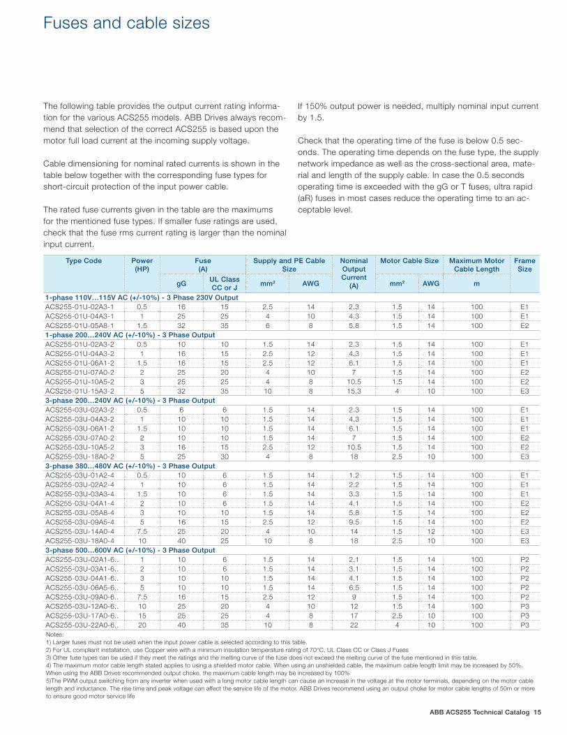
ABB ACS255 Technical Catalog 15
Fuses and cable sizes
The following table provides the output current rating informa-tion for the various ACS255 models. ABB Drives always recom-mend that selection of the correct ACS255 is based upon the motor full load current at the incoming supply voltage.
Cable dimensioning for nominal rated currents is shown in the table below together with the corresponding fuse types for short-circuit protection of the input power cable.
The rated fuse currents given in the table are the maximums for the mentioned fuse types. If smaller fuse ratings are used, check that the fuse rms current rating is larger than the nominal input current.
If 150% output power is needed, multiply nominal input current by 1.5.
Check that the operating time of the fuse is below 0.5 sec-onds. The operating time depends on the fuse type, the supply network impedance as well as the cross-sectional area, mate-rial and length of the supply cable. In case the 0.5 seconds operating time is exceeded with the gG or T fuses, ultra rapid (aR) fuses in most cases reduce the operating time to an ac-ceptable level.
Type Code Power (HP)
Fuse (A)
Supply and PE Cable Size
Nominal Output Current
(A)
Motor Cable Size Maximum Motor Cable Length
Frame Size
gGUL Class CC or J
mm2 AWG mm2 AWG m
1-phase 110V…115V AC (+/-10%) - 3 Phase 230V OutputACS255-01U-02A3-1 0.5 16 15 2.5 14 2.3 1.5 14 100 E1ACS255-01U-04A3-1 1 25 25 4 10 4.3 1.5 14 100 E1ACS255-01U-05A8-1 1.5 32 35 6 8 5.8 1.5 14 100 E21-phase 200…240V AC (+/-10%) - 3 Phase OutputACS255-01U-02A3-2 0.5 10 10 1.5 14 2.3 1.5 14 100 E1ACS255-01U-04A3-2 1 16 15 2.5 12 4.3 1.5 14 100 E1ACS255-01U-06A1-2 1.5 16 15 2.5 12 6.1 1.5 14 100 E1ACS255-01U-07A0-2 2 25 20 4 10 7 1.5 14 100 E2ACS255-01U-10A5-2 3 25 25 4 8 10.5 1.5 14 100 E2ACS255-01U-15A3-2 5 32 35 10 8 15.3 4 10 100 E33-phase 200…240V AC (+/-10%) - 3 Phase OutputACS255-03U-02A3-2 0.5 6 6 1.5 14 2.3 1.5 14 100 E1ACS255-03U-04A3-2 1 10 10 1.5 14 4.3 1.5 14 100 E1ACS255-03U-06A1-2 1.5 10 10 1.5 14 6.1 1.5 14 100 E1ACS255-03U-07A0-2 2 10 10 1.5 14 7 1.5 14 100 E2ACS255-03U-10A5-2 3 16 15 2.5 12 10.5 1.5 14 100 E2ACS255-03U-18A0-2 5 25 30 4 8 18 2.5 10 100 E33-phase 380…480V AC (+/-10%) - 3 Phase OutputACS255-03U-01A2-4 0.5 10 6 1.5 14 1.2 1.5 14 100 E1ACS255-03U-02A2-4 1 10 6 1.5 14 2.2 1.5 14 100 E1ACS255-03U-03A3-4 1.5 10 6 1.5 14 3.3 1.5 14 100 E1ACS255-03U-04A1-4 2 10 6 1.5 14 4.1 1.5 14 100 E2ACS255-03U-05A8-4 3 10 10 1.5 14 5.8 1.5 14 100 E2ACS255-03U-09A5-4 5 16 15 2.5 12 9.5 1.5 14 100 E2ACS255-03U-14A0-4 7.5 25 20 4 10 14 1.5 12 100 E3ACS255-03U-18A0-4 10 40 25 10 8 18 2.5 10 100 E33-phase 500…600V AC (+/-10%) - 3 Phase OutputACS255-03U-02A1-6.. 1 10 6 1.5 14 2.1 1.5 14 100 P2ACS255-03U-03A1-6.. 2 10 6 1.5 14 3.1 1.5 14 100 P2ACS255-03U-04A1-6.. 3 10 10 1.5 14 4.1 1.5 14 100 P2ACS255-03U-06A5-6.. 5 10 10 1.5 14 6.5 1.5 14 100 P2ACS255-03U-09A0-6.. 7.5 16 15 2.5 12 9 1.5 14 100 P2ACS255-03U-12A0-6.. 10 25 20 4 10 12 1.5 14 100 P3ACS255-03U-17A0-6.. 15 25 25 4 8 17 2.5 10 100 P3ACS255-03U-22A0-6.. 20 40 35 10 8 22 4 10 100 P3Notes: 1) Larger fuses must not be used when the input power cable is selected according to this table. 2) For UL compliant installation, use Copper wire with a minimum insulation temperature rating of 70°C, UL Class CC or Class J Fuses 3) Other fuse types can be used if they meet the ratings and the melting curve of the fuse does not exceed the melting curve of the fuse mentioned in this table. 4) The maximum motor cable length stated applies to using a shielded motor cable. When using an unshielded cable, the maximum cable length limit may be increased by 50%. When using the ABB Drives recommended output choke, the maximum cable length may be increased by 100% 5)The PWM output switching from any inverter when used with a long motor cable length can cause an increase in the voltage at the motor terminals, depending on the motor cable length and inductance. The rise time and peak voltage can affect the service life of the motor. ABB Drives recommend using an output choke for motor cable lengths of 50m or more to ensure good motor service life

16 ABB ACS255 Technical Catalog
+24 Volt
Run (Enable)
For / Rev
Analog / Preset
+ 10 Volts
Reference
0 Volts
+24 Volt
Run (Enable)
Analog / Preset
Preset 1 / Preset 2
+ 10 Volts
Reference
0 Volts
Analog speed input with 1 preset speed and fwd/rev switch
Analog speed input with 2 preset speeds 4 preset speeds and max speed select switch.Effectively giving 5 preset speeds
+24 Volt
Run (Enable)
Preset Speeds 1-4Select
Preset / Max
Control connections for 115, 240 & 480 V drives
IP66 (NEMA 4X) Switched Units
IP20 & IP66 (NEMA 4X) Non-Switched Units
Typical I/O Connections
M
1 +24V Output
2 Digital Input 1
3 Digital Input 2
4 Digital Input 3
5 +10V Output
6 Analog Input 1
7 0V
11
10
Analog Output 8
0V 9V
IsolatorMCB or
Fuse
3 phase AC input 50/60Hz
L1/L
L2/N
L3
Earth Earth
W
V
U
Optional Brake Resistor
+DC BR(Sizes 2 & 3)
Relay Common
Relay Contact
Cable Screen
0-10V
Stop - Run
Analog - Preset
Fwd - Rev
Optional External
Input Choke
Optional External
Input Filter
1 phase AC input 50/60Hz
Default External Analog & Digital
Input Connections
Analog Speed
Reference10kΩ nominal 1kΩ minimum
Power ConnectionsA Incoming Power SourceB External Mains DisconnectC External FuseD Optional Input ChokeE Optional Input FilterF Optional Brake ResistorG Shielded Motor CableI Relay Output
Control Connections1 + 24 Volt (100mA) User Output2 Digital Input 1: Drive Run / Stop3 Digital Input 2: Forward / Reverse4 Digital Input 3: Analog / Preset Speed5 + 10 Volt Output6 Analog Input 1: 0 – 10 Volt7 0 Volt8 Analog Output: 0 – 10 Volts9 0 Volt10 Relay Output11 ‘Drive READY’ = Closed
M
1
2
3
4
5
6
7
11
10
8
9V
L1/L
L2/N
L3
PE PE
W
V
U
+DC BR
G
H
I
FDCB
A
E
J
Power ConnectionsA Incoming Power SourceB External FuseC Optional Input ChokeD Optional Input FilterE Internal Mains DisconnectF Optional Brake ResistorG Shielded Motor CableI Relay Output
Control ConnectionsJ Internal Forward / Off / Reverse SwitchK Internal Speed Control Pot
8 Analog Output: 0 – 10 Volts9 0 Volt10 Relay Output11 ‘Drive READY’ = Closed
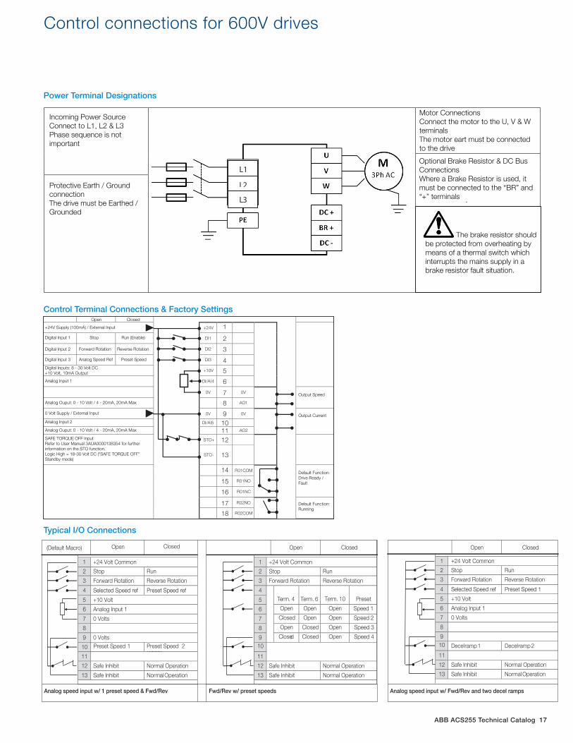
ABB ACS255 Technical Catalog 17
Control connections for 600V drives
(Default Macro) Open Closed
Fwd/Rev w/ preset speeds
Open Closed
1 +24 Volt Common 1 +24 Volt Common
2 Stop Run 2 Stop Run
3 Forward Rotation Reverse Rotation 3 Forward Rotation Reverse Rotation
4 Selected Speed ref Preset Speed ref 4 Term. 4 Term. 6 Term. 10 Preset 5 +10 Volt 5
6 Analog Input 1 6 Open Open Open Speed 1
7 0 Volts 7 Closed Open Open Speed 2
8 8 Open Closed Open Speed 3
9 0 Volts 9 Closed Closed Open Speed 4
10 Preset Speed 1 Preset Speed 2 (1203(
10ormal
Oper
11 11
12 Safe Inhibit Normal Operation 12 Safe Inhibit Normal Operation
13 Safe Inhibit Normal Operation 13 Safe Inhibit Normal Operation
1 +24 Volt Common
2 Stop Run
3 Forward Rotation Reverse Rotation
4 Selected Speed ref Preset Speed 1
5 +10 Volt
6 Analog Input 1
7 0 Volts
8
9 10ormalO
Decel ramp 1 Decel ramp 2
11
12 Safe Inhibit Normal Operation
13 Safe Inhibit Normal Operation
Open Closed
Analog speed input w/ 1 preset speed & Fwd/Rev Analog speed input w/ Fwd/Rev and two decel ramps
Power Terminal Designations
Control Terminal Connections & Factory Settings
Typical I/O Connections
+24V 1
DI1 2
DI2 3
DI3 4
+10V 5
DI/AI4 6
0V 7 0V
8 AO1
0V 9 0V
DI/AI5 10 11 AO2
STO+ 12
STO- 13
14 R01COM
15 R01NO
16 R01NC
17 R02NO
18 R02COM
Open Closed
+24V Supply (100mA) / External Input
Digital Input 1 Stop Run (Enable)
Digital Input 2 Forward Rotation Reverse Rotation
Digital Input 3 Analog Speed Ref Preset Speed
Digital Inputs: 8 - 30 Volt DC+10 Volt, 10mA Output
Analog Input 1
Analog Ouput: 0 - 10 Volt / 4 - 20mA, 20mA Max
0 Volt Supply / External Input
Analog Input 2
Analog Ouput: 0 - 10 Volt / 4 - 20mA, 20mA Max
SAFE TORQUE OFF InputRefer to User Manual 3AUA0000138354 for furtherinformation on the STO function.Logic High = 18-30 Volt DC ("SAFE TORQUE OFF" Standby mode)
Output Speed
Output Current
Default Function: Drive Ready / Fault
Default Function:Running
.
L1
L2
L3
Incoming Power SourceConnect to L1, L2 & L3Phase sequence is not important
Protective Earth / Ground connectionThe drive must be Earthed / Grounded
Motor ConnectionsConnect the motor to the U, V & W terminalsThe motor eart must be connectedto the drive
Optional Brake Resistor & DC BusConnectionsWhere a Brake Resistor is used, it must be connected to the “BR” and “+” terminals
The brake resistor should be protected from overheating by means of a thermal switch which interrupts the mains supply in a brake resistor fault situation.
18 ABB ACS255 Technical Catalog
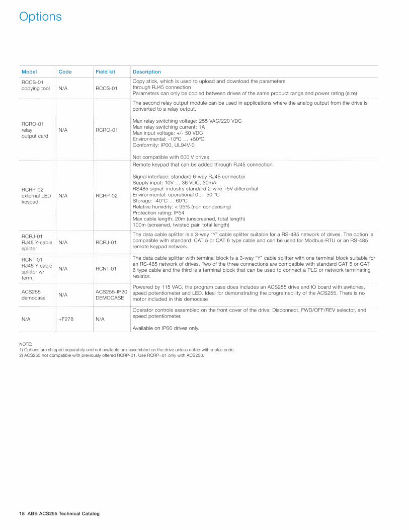
Model Code Field kit Description
RCCS-01 copying tool N/A RCCS-01
Copy stick, which is used to upload and download the parameters through RJ45 connectionParameters can only be copied between drives of the same product range and power rating (size)
RCRO-01 relay output card
N/A RCRO-01
The second relay output module can be used in applications where the analog output from the drive is converted to a relay output.
Max relay switching voltage: 255 VAC/220 VDCMax relay switching current: 1AMax input voltage: +/- 50 VDCEnvironmental: -10ºC … +50ºCConformity: IP00, UL94V-0 Not compatible with 600 V drives
RCRP-02 external LED keypad
N/A RCRP-02
Remote keypad that can be added through RJ45 connection.
Signal interface: standard 6-way RJ45 connectorSupply input: 10V … 36 VDC, 30mARS485 signal: industry standard 2-wire +5V differentialEnvironmental: operational 0 … 50 °CStorage: -40°C … 60°CRelative humidity: < 95% (non condensing)Protection rating: IP54Max cable length: 20m (unscreened, total length)100m (screened, twisted pair, total length)
RCRJ-01RJ45 Y-cable splitter
N/A RCRJ-01
The data cable splitter is a 3-way “Y” cable splitter suitable for a RS-485 network of drives. The option is compatible with standard CAT 5 or CAT 6 type cable and can be used for Modbus-RTU or an RS-485 remote keypad network.
RCNT-01RJ45 Y-cable splitter w/ term.
N/A RCNT-01
The data cable splitter with terminal block is a 3-way “Y” cable splitter with one terminal block suitable for an RS-485 network of drives. Two of the three connections are compatible with standard CAT 5 or CAT 6 type cable and the third is a terminal block that can be used to connect a PLC or network terminating resistor.
ACS255democase
N/AACS255-IP20DEMOCASE
Powered by 115 VAC, the program case does includes an ACS255 drive and IO board with switches, speed potentiometer and LED. Ideal for demonstrating the programability of the ACS255. There is no motor included in this democase
N/A +F278 N/A
Operator controls assembled on the front cover of the drive: Disconnect, FWD/OFF/REV selector, and speed potentiometer. Available on IP66 drives only.
Options
NOTE: 1) Options are shipped separately and not available pre-assembled on the drive unless noted with a plus code.2) ACS255 not compatible with previously offered RCRP-01. Use RCRP=01 only with ACS250.

ABB ACS255 Technical Catalog 19
Single-phase 100-120 V applications, stopping duty only Type CR resistors (availale for the small HP drives as listed below)
DutyCycle=3sec on/27sec off DutyCycle=10sec on/50sec off
Drive type code HP CR part no. Ohms Watts CR part no. Ohms Watts
ACS255-01U-05A8-1 1.5 P14494-CR-06 50 100 P14494-CR-18 50 200
DutyCycle=30sec on/180sec off DutyCycle=60sec on/180sec off
Drive type code HP CR part no. Ohms Watts CR part no. Ohms Watts
ACS255-01U-05A8-1 1.5 P14494-CR-24 50 300 P14494-CR-32 50 400
Standard enclosed resistor packagesDutyCycle=3sec on/27sec off DutyCycle=10sec on/50sec off
Drive type code HP Resistor part no. Ohms Watts Resistor part no. Ohms Watts
ACS255-01U-05A8-1 1.5 P14494-24 45 300 P14494-24 45 300
DutyCycle=30sec on/180sec off DutyCycle=60sec on/180sec off
Drive type code HP Resistor part no. Ohms Watts Resistor part no. Ohms Watts
ACS255-01U-05A8-1 1.5 P14494-24 45 300 P14494-24 45 300Notes: To determine resistor type, dimensions and weights refer to Resistor Technical Data Tables
Braking resistors
Single-phase 200-240 V applications, stopping duty only Type CR resistors (availale for the small HP drives as listed below)
DutyCycle=3sec on/27sec off DutyCycle=10sec on/50sec off
Drive type code HP CR part no. Ohms Watts CR part no. Ohms Watts
ACS255-01U-10A5-2 3 P14494-CR-12 50 150 P14494-CR-24 50 300
DutyCycle=30sec on/180sec off DutyCycle=60sec on/180sec off
Drive type code HP CR part no. Ohms Watts CR part no. Ohms Watts
ACS255-01U-10A5-2 3 P14494-CR-32 50 400
Standard enclosed resistor packagesDutyCycle=3sec on/27sec off DutyCycle=10sec on/50sec off
Drive type code HP Resistor part no. Ohms Watts Resistor part no. Ohms Watts
ACS255-01U-10A5-2 3 P14494-31 35 300 P14494-31 35 300
DutyCycle=30sec on/180sec off DutyCycle=60sec on/180sec off
Drive type code HP Resistor part no. Ohms Watts Resistor part no. Ohms Watts
ACS255-01U-10A5-2 3 P14494-32 35 820 P14494-32 35 820Notes: To determine resistor type, dimensions and weights refer to Resistor Technical Data Tables

20 ABB ACS255 Technical Catalog
Braking resistors
Three-phase 200-240 V applications, stopping duty only Type CR resistors (availale for the small HP drives as listed below)
DutyCycle=3sec on/27sec off DutyCycle=10sec on/50sec off
Drive type code HP CR part no. Ohms Watts CR part no. Ohms Watts
ACS255-03U-07A0-2 2 P14494-CR-06 50 100 P14494-CR-18 50 200
ACS255-03U-10A5-2 3 P14494-CR-12 50 150 P14494-CR-24 50 300
ACS255-03U-18A0-2 5 P14494-CR-26 40 300 P14494-CR-34 40 400
DutyCycle=30sec on/180sec off DutyCycle=60sec on/180sec off
Drive type code HP CR part no. Ohms Watts CR part no. Ohms Watts
ACS255-03U-07A0-2 2 P14494-CR-24 50 300 P14494-CR-32 50 400
ACS255-03U-10A5-2 3 P14494-CR-32 50 400
Standard enclosed resistor packagesDutyCycle=3sec on/27sec off DutyCycle=10sec on/50sec off
Drive type code HP Resistor part no. Ohms Watts Resistor part no. Ohms Watts
ACS255-03U-07A0-2 2 P14494-31 35 300 P14494-31 35 300
ACS255-03U-10A5-2 3 P14494-31 35 300 P14494-31 35 300
ACS255-03U-18A0-2 5 P14494-31 35 300 P14494-32 35 820
DutyCycle=30sec on/180sec off DutyCycle=60sec on/180sec off
Drive type code HP Resistor part no. Ohms Watts Resistor part no. Ohms Watts
ACS255-01U-07A0-2 2 P14494-31 35 300 P14494-32 35 820
ACS255-01U-10A5-2 3 P14494-32 35 820 P14494-32 35 820
ACS255-03U-18A0-2 5 P14494-32 35 820 P14494-32 35 820
Notes: To determine resistor type, dimensions and weights refer to Resistor Technical Data Tables
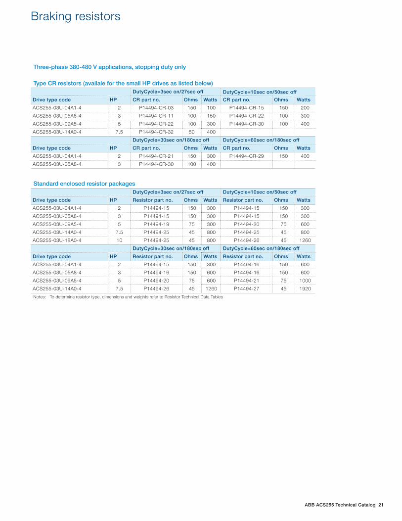
ABB ACS255 Technical Catalog 21
Braking resistors Braking resistors
Three-phase 380-480 V applications, stopping duty only Type CR resistors (availale for the small HP drives as listed below)
DutyCycle=3sec on/27sec off DutyCycle=10sec on/50sec off
Drive type code HP CR part no. Ohms Watts CR part no. Ohms Watts
ACS255-03U-04A1-4 2 P14494-CR-03 150 100 P14494-CR-15 150 200
ACS255-03U-05A8-4 3 P14494-CR-11 100 150 P14494-CR-22 100 300
ACS255-03U-09A5-4 5 P14494-CR-22 100 300 P14494-CR-30 100 400
ACS255-03U-14A0-4 7.5 P14494-CR-32 50 400
DutyCycle=30sec on/180sec off DutyCycle=60sec on/180sec off
Drive type code HP CR part no. Ohms Watts CR part no. Ohms Watts
ACS255-03U-04A1-4 2 P14494-CR-21 150 300 P14494-CR-29 150 400
ACS255-03U-05A8-4 3 P14494-CR-30 100 400
Standard enclosed resistor packagesDutyCycle=3sec on/27sec off DutyCycle=10sec on/50sec off
Drive type code HP Resistor part no. Ohms Watts Resistor part no. Ohms Watts
ACS255-03U-04A1-4 2 P14494-15 150 300 P14494-15 150 300
ACS255-03U-05A8-4 3 P14494-15 150 300 P14494-15 150 300
ACS255-03U-09A5-4 5 P14494-19 75 300 P14494-20 75 600
ACS255-03U-14A0-4 7.5 P14494-25 45 800 P14494-25 45 800
ACS255-03U-18A0-4 10 P14494-25 45 800 P14494-26 45 1260
DutyCycle=30sec on/180sec off DutyCycle=60sec on/180sec off
Drive type code HP Resistor part no. Ohms Watts Resistor part no. Ohms Watts
ACS255-03U-04A1-4 2 P14494-15 150 300 P14494-16 150 600
ACS255-03U-05A8-4 3 P14494-16 150 600 P14494-16 150 600
ACS255-03U-09A5-4 5 P14494-20 75 600 P14494-21 75 1000
ACS255-03U-14A0-4 7.5 P14494-26 45 1260 P14494-27 45 1920
Notes: To determine resistor type, dimensions and weights refer to Resistor Technical Data Tables
22 ABB ACS255 Technical Catalog
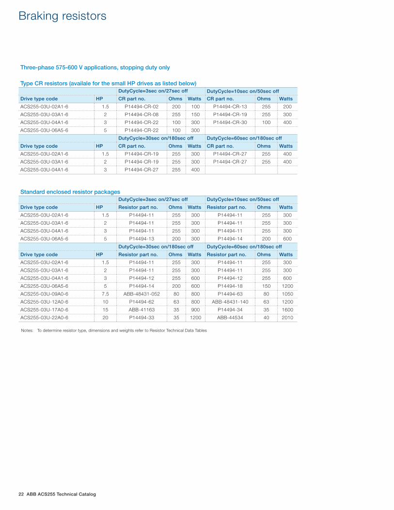
Braking resistors
Three-phase 575-600 V applications, stopping duty only Type CR resistors (availale for the small HP drives as listed below)
DutyCycle=3sec on/27sec off DutyCycle=10sec on/50sec off
Drive type code HP CR part no. Ohms Watts CR part no. Ohms Watts
ACS255-03U-02A1-6 1.5 P14494-CR-02 200 100 P14494-CR-13 255 200
ACS255-03U-03A1-6 2 P14494-CR-08 255 150 P14494-CR-19 255 300
ACS255-03U-04A1-6 3 P14494-CR-22 100 300 P14494-CR-30 100 400
ACS255-03U-06A5-6 5 P14494-CR-22 100 300
DutyCycle=30sec on/180sec off DutyCycle=60sec on/180sec off
Drive type code HP CR part no. Ohms Watts CR part no. Ohms Watts
ACS255-03U-02A1-6 1.5 P14494-CR-19 255 300 P14494-CR-27 255 400
ACS255-03U-03A1-6 2 P14494-CR-19 255 300 P14494-CR-27 255 400
ACS255-03U-04A1-6 3 P14494-CR-27 255 400
Standard enclosed resistor packagesDutyCycle=3sec on/27sec off DutyCycle=10sec on/50sec off
Drive type code HP Resistor part no. Ohms Watts Resistor part no. Ohms Watts
ACS255-03U-02A1-6 1.5 P14494-11 255 300 P14494-11 255 300
ACS255-03U-03A1-6 2 P14494-11 255 300 P14494-11 255 300
ACS255-03U-04A1-6 3 P14494-11 255 300 P14494-11 255 300
ACS255-03U-06A5-6 5 P14494-13 200 300 P14494-14 200 600
DutyCycle=30sec on/180sec off DutyCycle=60sec on/180sec off
Drive type code HP Resistor part no. Ohms Watts Resistor part no. Ohms Watts
ACS255-03U-02A1-6 1.5 P14494-11 255 300 P14494-11 255 300
ACS255-03U-03A1-6 2 P14494-11 255 300 P14494-11 255 300
ACS255-03U-04A1-6 3 P14494-12 255 600 P14494-12 255 600
ACS255-03U-06A5-6 5 P14494-14 200 600 P14494-18 150 1200
ACS255-03U-09A0-6 7.5 ABB-48431-052 80 800 P14494-63 80 1050
ACS255-03U-12A0-6 10 P14494-62 63 800 ABB-48431-140 63 1200
ACS255-03U-17A0-6 15 ABB-41163 35 900 P14494-34 35 1600
ACS255-03U-22A0-6 20 P14494-33 35 1200 ABB-44534 40 2010
Notes: To determine resistor type, dimensions and weights refer to Resistor Technical Data Tables
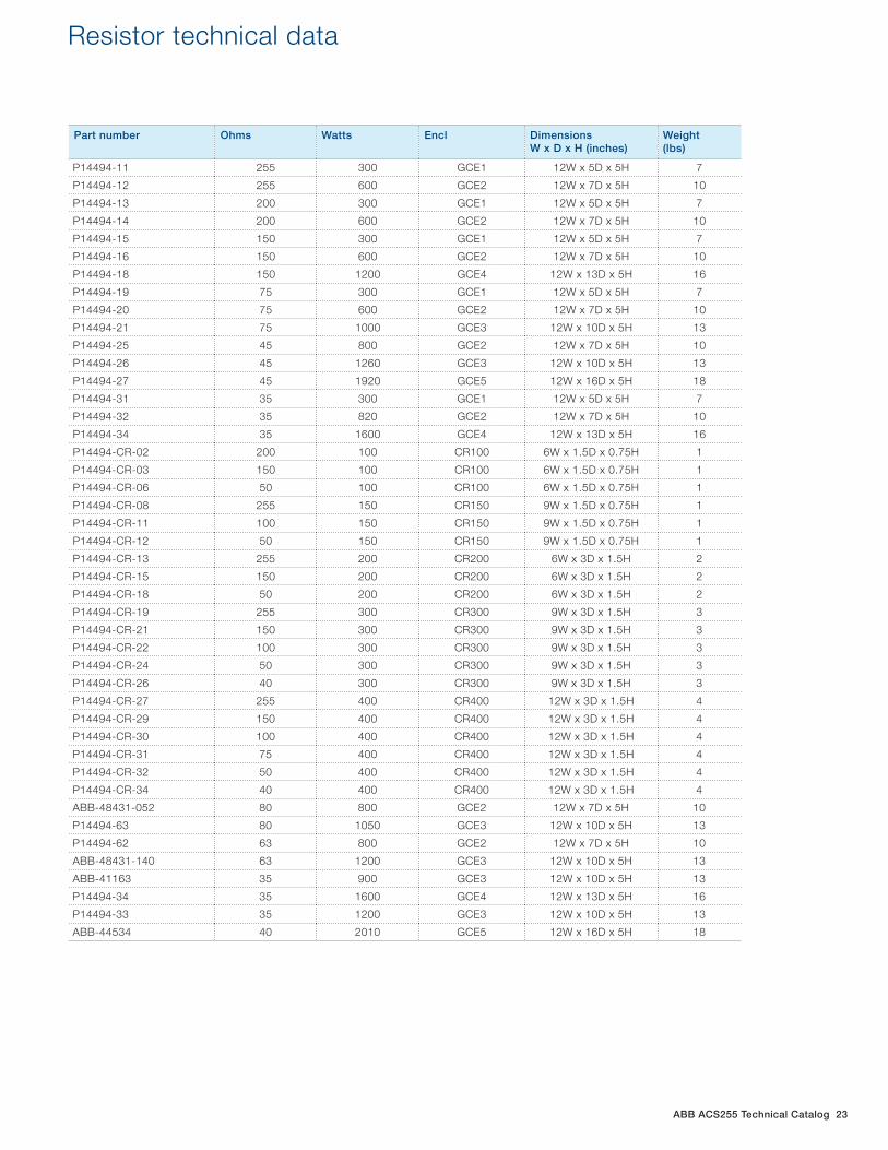
ABB ACS255 Technical Catalog 23
Resistor technical data
Part number Ohms Watts Encl Dimensions W x D x H (inches)
Weight(lbs)
P14494-11 255 300 GCE1 12W x 5D x 5H 7
P14494-12 255 600 GCE2 12W x 7D x 5H 10
P14494-13 200 300 GCE1 12W x 5D x 5H 7
P14494-14 200 600 GCE2 12W x 7D x 5H 10
P14494-15 150 300 GCE1 12W x 5D x 5H 7
P14494-16 150 600 GCE2 12W x 7D x 5H 10
P14494-18 150 1200 GCE4 12W x 13D x 5H 16
P14494-19 75 300 GCE1 12W x 5D x 5H 7
P14494-20 75 600 GCE2 12W x 7D x 5H 10
P14494-21 75 1000 GCE3 12W x 10D x 5H 13
P14494-25 45 800 GCE2 12W x 7D x 5H 10
P14494-26 45 1260 GCE3 12W x 10D x 5H 13
P14494-27 45 1920 GCE5 12W x 16D x 5H 18
P14494-31 35 300 GCE1 12W x 5D x 5H 7
P14494-32 35 820 GCE2 12W x 7D x 5H 10
P14494-34 35 1600 GCE4 12W x 13D x 5H 16
P14494-CR-02 200 100 CR100 6W x 1.5D x 0.75H 1
P14494-CR-03 150 100 CR100 6W x 1.5D x 0.75H 1
P14494-CR-06 50 100 CR100 6W x 1.5D x 0.75H 1
P14494-CR-08 255 150 CR150 9W x 1.5D x 0.75H 1
P14494-CR-11 100 150 CR150 9W x 1.5D x 0.75H 1
P14494-CR-12 50 150 CR150 9W x 1.5D x 0.75H 1
P14494-CR-13 255 200 CR200 6W x 3D x 1.5H 2
P14494-CR-15 150 200 CR200 6W x 3D x 1.5H 2
P14494-CR-18 50 200 CR200 6W x 3D x 1.5H 2
P14494-CR-19 255 300 CR300 9W x 3D x 1.5H 3
P14494-CR-21 150 300 CR300 9W x 3D x 1.5H 3
P14494-CR-22 100 300 CR300 9W x 3D x 1.5H 3
P14494-CR-24 50 300 CR300 9W x 3D x 1.5H 3
P14494-CR-26 40 300 CR300 9W x 3D x 1.5H 3
P14494-CR-27 255 400 CR400 12W x 3D x 1.5H 4
P14494-CR-29 150 400 CR400 12W x 3D x 1.5H 4
P14494-CR-30 100 400 CR400 12W x 3D x 1.5H 4
P14494-CR-31 75 400 CR400 12W x 3D x 1.5H 4
P14494-CR-32 50 400 CR400 12W x 3D x 1.5H 4
P14494-CR-34 40 400 CR400 12W x 3D x 1.5H 4
ABB-48431-052 80 800 GCE2 12W x 7D x 5H 10
P14494-63 80 1050 GCE3 12W x 10D x 5H 13
P14494-62 63 800 GCE2 12W x 7D x 5H 10
ABB-48431-140 63 1200 GCE3 12W x 10D x 5H 13
ABB-41163 35 900 GCE3 12W x 10D x 5H 13
P14494-34 35 1600 GCE4 12W x 13D x 5H 16
P14494-33 35 1200 GCE3 12W x 10D x 5H 13
ABB-44534 40 2010 GCE5 12W x 16D x 5H 18
24 ABB ACS255 Technical Catalog
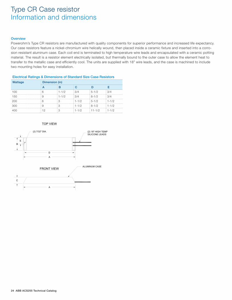
Type CR Case resistor Information and dimensions
OverviewPowerohm’s Type CR resistors are manufactured with quality components for superior performance and increased life expectancy. Our case resistors feature a nickel-chromium wire helically wound, then placed inside a ceramic fixture and inserted into a corro-sion resistant aluminum case. Each coil end is terminated to high temperature wire leads and encapsulated with a ceramic potting material. The result is a resistor element electrically isolated, but thermally bound to the outer case to allow the element heat to transfer to the metallic case and efficiently cool. The units are supplied with 18” wire leads, and the case is machined to include two mounting holes for easy installation.
Electrical Ratings & Dimensions of Standard Size Case Resistors
Wattage Dimension (in)
A B C D E
100 6 1-1/2 3/4 5-1/2 3/4
150 9 1-1/2 3/4 8-1/2 3/4
200 6 3 1-1/2 5-1/2 1-1/2
300 9 3 1-1/2 8-1/2 1-1/2
400 12 3 1-1/2 11-1/2 1-1/2
B
C
D
A
E
(2) 18" HIGH TEMPSILICONE LEADS
(2) 7/32" DIA.
TOP VIEW
FRONT VIEWALUMINUM CASE
A
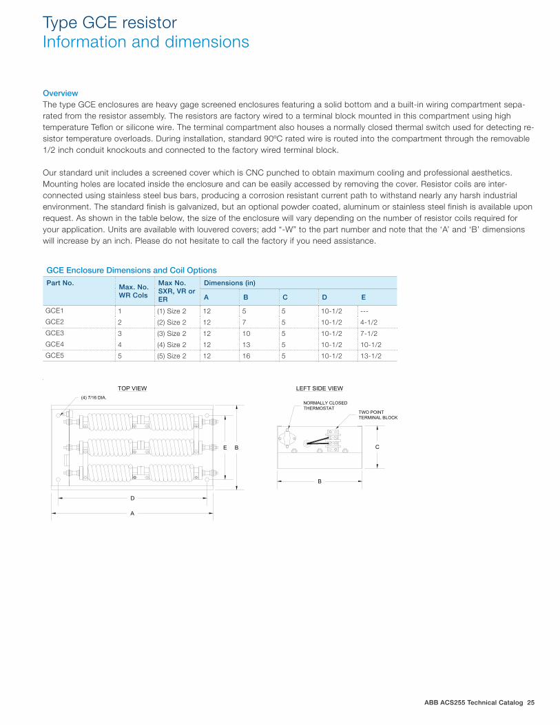
ABB ACS255 Technical Catalog 25
Type GCE resistor Information and dimensions
OverviewThe type GCE enclosures are heavy gage screened enclosures featuring a solid bottom and a built-in wiring compartment sepa-rated from the resistor assembly. The resistors are factory wired to a terminal block mounted in this compartment using high temperature Teflon or silicone wire. The terminal compartment also houses a normally closed thermal switch used for detecting re-sistor temperature overloads. During installation, standard 90ºC rated wire is routed into the compartment through the removable 1/2 inch conduit knockouts and connected to the factory wired terminal block.
Our standard unit includes a screened cover which is CNC punched to obtain maximum cooling and professional aesthetics. Mounting holes are located inside the enclosure and can be easily accessed by removing the cover. Resistor coils are inter-connected using stainless steel bus bars, producing a corrosion resistant current path to withstand nearly any harsh industrial environment. The standard finish is galvanized, but an optional powder coated, aluminum or stainless steel finish is available upon request. As shown in the table below, the size of the enclosure will vary depending on the number of resistor coils required for your application. Units are available with louvered covers; add “-W” to the part number and note that the ‘A’ and ‘B’ dimensions will increase by an inch. Please do not hesitate to call the factory if you need assistance.
GCE Enclosure Dimensions and Coil Options
Part No.Max. No. WR Cols
Max No. SXR, VR or ER
Dimensions (in)
A B C D E
GCE1 1 (1) Size 2 12 5 5 10-1/2 ---
GCE2 2 (2) Size 2 12 7 5 10-1/2 4-1/2
GCE3 3 (3) Size 2 12 10 5 10-1/2 7-1/2
GCE4 4 (4) Size 2 12 13 5 10-1/2 10-1/2
GCE5 5 (5) Size 2 12 16 5 10-1/2 13-1/2
C
B
B
A
D
E
NORMALLY CLOSEDTHERMOSTAT
TWO POINTTERMINAL BLOCK
(4) 7/16 DIA.
TOP VIEW LEFT SIDE VIEW
26 ABB ACS255 Technical Catalog
Installation instructions for Powerohm Brake Resistors
CONSTRUCTION: Powerohm braking resistors consists of smoothwound, wirewound or edgewound type resistor coils mounted in ventilated enclosures. All current carrying components used to manufacture our resistor coils including the elements and termi-nals are stainless steel for maximum corrosion resistance. Standard enclosures will be mill galvanized with terminals factory wired to a terminal block and normally closed thermal switch. Braking resistors are available with a variety of options such as special enclosure finishes and outdoor ratings.
INSPECTION: Upon receipt of your Powerohm Braking Resistor, be sure to inspect the unit carefully for any shipping damage. After unpacking, check the unit for loose, broken, bent or otherwise damaged parts due to shipping. Report any shipping damage immediately to the freight carrier. Be sure to verify that the part number and ratings listed on the nameplate conform to the order specification. The ohm rating listed on the nameplate is critical (too low of an ohm value may cause damage to the drive). INSTALLATION: IMPORTANT: The National Electric Code (NEC) and local regulations govern the installation and wiring of electrical equipment such as braking resistors. DC power wiring, AC power wiring, control wiring and conduit must be installed in accordance with these codes.
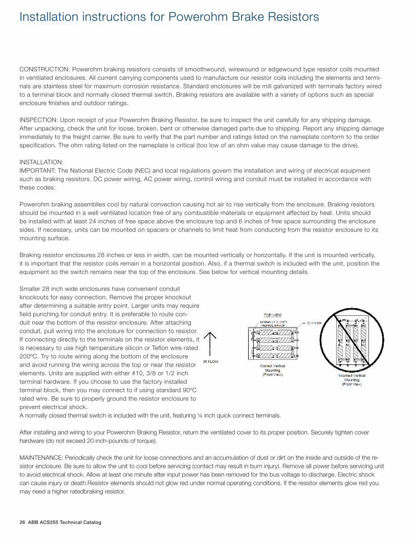
Powerohm braking assemblies cool by natural convection causing hot air to rise vertically from the enclosure. Braking resistors should be mounted in a well ventilated location free of any combustible materials or equipment affected by heat. Units should be installed with at least 24 inches of free space above the enclosure top and 6 inches of free space surrounding the enclosure sides. If necessary, units can be mounted on spacers or channels to limit heat from conducting from the resistor enclosure to its mounting surface.
Braking resistor enclosures 28 inches or less in width, can be mounted vertically or horizontally. If the unit is mounted vertically, it is important that the resistor coils remain in a horizontal position. Also, if a thermal switch is included with the unit, position the equipment so the switch remains near the top of the enclosure. See below for vertical mounting details.
Smaller 28 inch wide enclosures have convenient conduit knockouts for easy connection. Remove the proper knockout after determining a suitable entry point. Larger units may require field punching for conduit entry. It is preferable to route con-duit near the bottom of the resistor enclosure. After attaching conduit, pull wiring into the enclosure for connection to resistor. If connecting directly to the terminals on the resistor elements, it is necessary to use high temperature silicon or Teflon wire rated 200ºC. Try to route wiring along the bottom of the enclosure and avoid running the wiring across the top or near the resistor elements. Units are supplied with either #10, 3/8 or 1/2 inch terminal hardware. If you choose to use the factory installed terminal block, then you may connect to if using standard 90ºC rated wire. Be sure to properly ground the resistor enclosure to prevent electrical shock.A normally closed thermal switch is included with the unit, featuring ¼ inch quick connect terminals. After installing and wiring to your Powerohm Braking Resistor, return the ventilated cover to its proper position. Securely tighten cover hardware (do not exceed 20 inch-pounds of torque). MAINTENANCE: Periodically check the unit for loose connections and an accumulation of dust or dirt on the inside and outside of the re-sistor enclosure. Be sure to allow the unit to cool before servicing (contact may result in burn injury). Remove all power before servicing unit to avoid electrical shock. Allow at least one minute after input power has been removed for the bus voltage to discharge. Electric shock can cause injury or death.Resistor elements should not glow red under normal operating conditions. If the resistor elements glow red you may need a higher ratedbraking resistor.
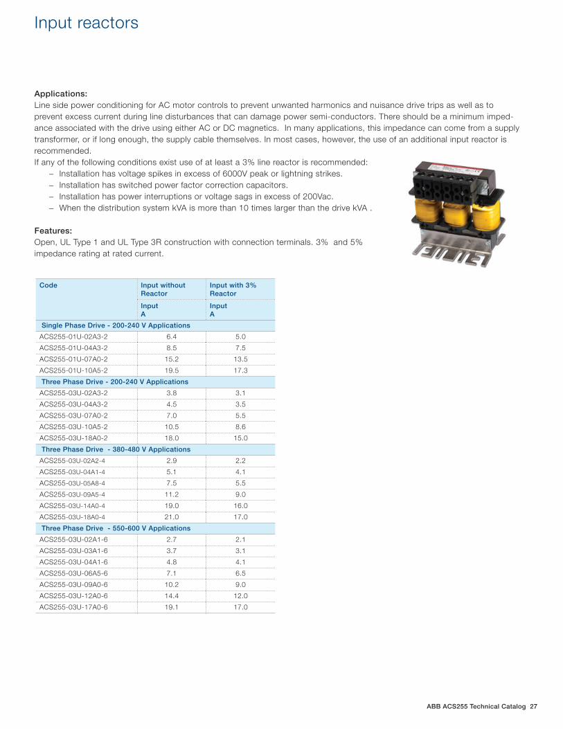
ABB ACS255 Technical Catalog 27
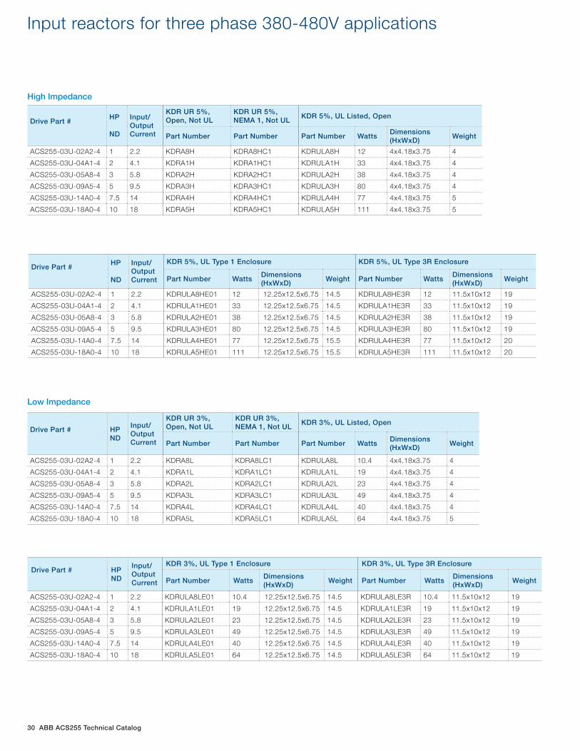
Input reactors
Applications: Line side power conditioning for AC motor controls to prevent unwanted harmonics and nuisance drive trips as well as to prevent excess current during line disturbances that can damage power semi-conductors. There should be a minimum imped-ance associated with the drive using either AC or DC magnetics. In many applications, this impedance can come from a supply transformer, or if long enough, the supply cable themselves. In most cases, however, the use of an additional input reactor is recommended. If any of the following conditions exist use of at least a 3% line reactor is recommended:
− Installation has voltage spikes in excess of 6000V peak or lightning strikes. − Installation has switched power factor correction capacitors. − Installation has power interruptions or voltage sags in excess of 200Vac. − When the distribution system kVA is more than 10 times larger than the drive kVA .
Features: Open, UL Type 1 and UL Type 3R construction with connection terminals. 3% and 5% impedance rating at rated current.
Code Input without Reactor
Input with 3% Reactor
InputA
InputA
Single Phase Drive - 200-240 V Applications
ACS255-01U-02A3-2 6.4 5.0
ACS255-01U-04A3-2 8.5 7.5
ACS255-01U-07A0-2 15.2 13.5
ACS255-01U-10A5-2 19.5 17.3
Three Phase Drive - 200-240 V Applications
ACS255-03U-02A3-2 3.8 3.1
ACS255-03U-04A3-2 4.5 3.5
ACS255-03U-07A0-2 7.0 5.5
ACS255-03U-10A5-2 10.5 8.6
ACS255-03U-18A0-2 18.0 15.0
Three Phase Drive - 380-480 V Applications
ACS255-03U-02A2-4 2.9 2.2
ACS255-03U-04A1-4 5.1 4.1
ACS255-03U-05A8-4 7.5 5.5
ACS255-03U-09A5-4 11.2 9.0
ACS255-03U-14A0-4 19.0 16.0
ACS255-03U-18A0-4 21.0 17.0
Three Phase Drive - 550-600 V Applications
ACS255-03U-02A1-6 2.7 2.1
ACS255-03U-03A1-6 3.7 3.1
ACS255-03U-04A1-6 4.8 4.1
ACS255-03U-06A5-6 7.1 6.5
ACS255-03U-09A0-6 10.2 9.0
ACS255-03U-12A0-6 14.4 12.0
ACS255-03U-17A0-6 19.1 17.0
28 ABB ACS255 Technical Catalog
Drive Part # HP ND
Input/Output Current
KDR UR 5%, Open, Not UL
KDR UR 5%, NEMA 1, Not UL
KDR 5%, UL Listed, Open
Part Number Part Number Part Number WattsDimensions (HxWxD)
Weight
ACS255-01U-02A3-2 0.5 2.3 KDRA53H KDRA53HC1 KDRULA53H 16.8 4x4.18x3.75 4
ACS255-01U-04A3-2 1 4.3 KDRA26H KDRA26HC1 KDRULA26H 30.5 4x4.18x3.75 4
ACS255-01U-07A0-2 2 7 KDRB25H KDRB25HC1 KDRULB25H 53.1 5x6x4 8
ACS255-01U-10A5-2 3 10.5 KDRB26H KDRB26HC1 KDRULB26H 66.5 5x6x4 8
Drive Part # HP ND
Input/Output Current
KDR 5%, UL Type 1 Enclosure KDR 5%, UL Type 3R Enclosure
Part Number WattsDimensions (HxWxD)
Weight Part Number WattsDimensions (HxWxD)
Weight
ACS255-01U-02A3-2 0.5 2.3 KDRULA53HE01 16.8 12.25x12.5x6.75 14.5 KDRULA53HE3R 16.8 11.5x10x12 19
ACS255-01U-04A3-2 1 4.3 KDRULA26HE01 30.5 12.25x12.5x6.75 14.5 KDRULA26HE3R 30.5 11.5x10x12 19
ACS255-01U-07A0-2 2 7 KDRULB25HE01 53.1 12.25x12.5x6.75 18.5 KDRULB25HE3R 53.1 11.5x10x12 23
ACS255-01U-10A5-2 3 10.5 KDRULB26HE01 66.5 12.25x12.5x6.75 18.5 KDRULB26HE3R 66.5 11.5x10x12 23
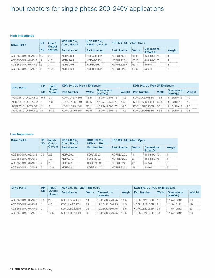
Input reactors for single phase 200-240V applications
High Impedance
Drive Part # HP ND
Input/Output Current
KDR UR 3%, Open, Not UL
KDR UR 3%, NEMA 1, Not UL
KDR 3%, UL Listed, Open
Part Number Part Number Part Number Watts Dimensions (HxWxD)
Weight
ACS255-01U-02A3-2 0.5 2.3 KDRA25L KDRA25LC1 KDRULA25L 11 4x4.18x3.75 4
ACS255-01U-04A3-2 1 4.3 KDRA27L KDRA27LC1 KDRULA27L 21 4x4.18x3.75 4
ACS255-01U-07A0-2 2 7 KDRB22L KDRB22LC1 KDRULB22L 38 5x6x4 8
ACS255-01U-10A5-2 3 10.5 KDRB22L KDRB22LC1 KDRULB22L 38 5x6x4 8
Drive Part # HP ND
Input/Output Current
KDR 3%, UL Type 1 Enclosure KDR 3%, UL Type 3R Enclosure
Part Number Watts Dimensions (HxWxD)
Weight Part Number Watts Dimensions (HxWxD)
Weight
ACS255-01U-02A3-2 0.5 2.3 KDRULA25LE01 11 12.25x12.5x6.75 14.5 KDRULA25LE3R 11 11.5x10x12 19
ACS255-01U-04A3-2 1 4.3 KDRULA27LE01 21 12.25x12.5x6.75 14.5 KDRULA27LE3R 21 11.5x10x12 19
ACS255-01U-07A0-2 2 7 KDRULB22LE01 38 12.25x12.5x6.75 18.5 KDRULB22LE3R 38 11.5x10x12 23
ACS255-01U-10A5-2 3 10.5 KDRULB22LE01 38 12.25x12.5x6.75 18.5 KDRULB22LE3R 38 11.5x10x12 23
Low Impedance
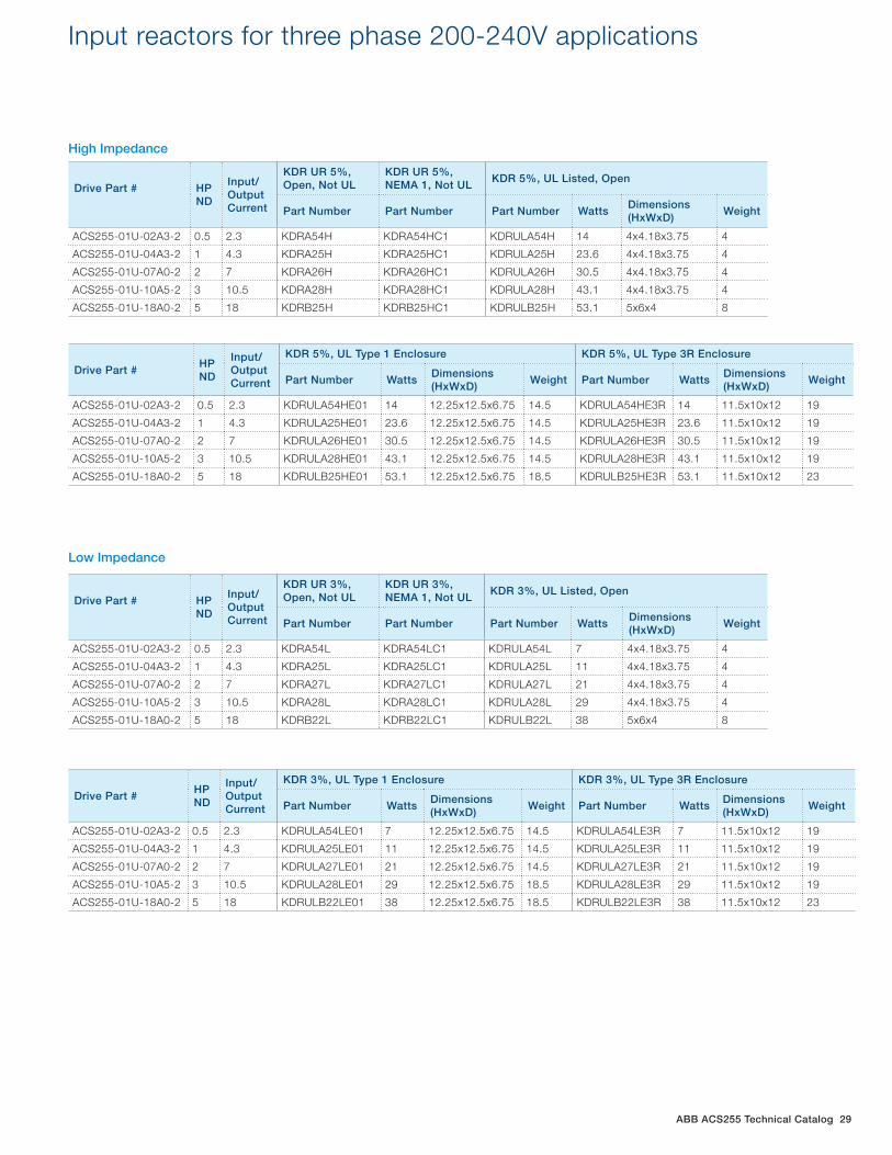
ABB ACS255 Technical Catalog 29
Drive Part # HP ND
Input/Output Current
KDR UR 5%, Open, Not UL
KDR UR 5%, NEMA 1, Not UL
KDR 5%, UL Listed, Open
Part Number Part Number Part Number WattsDimensions (HxWxD)
Weight
ACS255-01U-02A3-2 0.5 2.3 KDRA54H KDRA54HC1 KDRULA54H 14 4x4.18x3.75 4
ACS255-01U-04A3-2 1 4.3 KDRA25H KDRA25HC1 KDRULA25H 23.6 4x4.18x3.75 4
ACS255-01U-07A0-2 2 7 KDRA26H KDRA26HC1 KDRULA26H 30.5 4x4.18x3.75 4
ACS255-01U-10A5-2 3 10.5 KDRA28H KDRA28HC1 KDRULA28H 43.1 4x4.18x3.75 4
ACS255-01U-18A0-2 5 18 KDRB25H KDRB25HC1 KDRULB25H 53.1 5x6x4 8
Drive Part # HP ND
Input/Output Current
KDR 5%, UL Type 1 Enclosure KDR 5%, UL Type 3R Enclosure
Part Number WattsDimensions (HxWxD)
Weight Part Number WattsDimensions (HxWxD)
Weight
ACS255-01U-02A3-2 0.5 2.3 KDRULA54HE01 14 12.25x12.5x6.75 14.5 KDRULA54HE3R 14 11.5x10x12 19
ACS255-01U-04A3-2 1 4.3 KDRULA25HE01 23.6 12.25x12.5x6.75 14.5 KDRULA25HE3R 23.6 11.5x10x12 19
ACS255-01U-07A0-2 2 7 KDRULA26HE01 30.5 12.25x12.5x6.75 14.5 KDRULA26HE3R 30.5 11.5x10x12 19
ACS255-01U-10A5-2 3 10.5 KDRULA28HE01 43.1 12.25x12.5x6.75 14.5 KDRULA28HE3R 43.1 11.5x10x12 19
ACS255-01U-18A0-2 5 18 KDRULB25HE01 53.1 12.25x12.5x6.75 18.5 KDRULB25HE3R 53.1 11.5x10x12 23
Input reactors for three phase 200-240V applications
Drive Part # HP ND
Input/Output Current
KDR UR 3%, Open, Not UL
KDR UR 3%, NEMA 1, Not UL
KDR 3%, UL Listed, Open
Part Number Part Number Part Number WattsDimensions (HxWxD)
Weight
ACS255-01U-02A3-2 0.5 2.3 KDRA54L KDRA54LC1 KDRULA54L 7 4x4.18x3.75 4
ACS255-01U-04A3-2 1 4.3 KDRA25L KDRA25LC1 KDRULA25L 11 4x4.18x3.75 4
ACS255-01U-07A0-2 2 7 KDRA27L KDRA27LC1 KDRULA27L 21 4x4.18x3.75 4
ACS255-01U-10A5-2 3 10.5 KDRA28L KDRA28LC1 KDRULA28L 29 4x4.18x3.75 4
ACS255-01U-18A0-2 5 18 KDRB22L KDRB22LC1 KDRULB22L 38 5x6x4 8
Drive Part # HP ND
Input/Output Current
KDR 3%, UL Type 1 Enclosure KDR 3%, UL Type 3R Enclosure
Part Number WattsDimensions (HxWxD)
Weight Part Number WattsDimensions (HxWxD)
Weight
ACS255-01U-02A3-2 0.5 2.3 KDRULA54LE01 7 12.25x12.5x6.75 14.5 KDRULA54LE3R 7 11.5x10x12 19
ACS255-01U-04A3-2 1 4.3 KDRULA25LE01 11 12.25x12.5x6.75 14.5 KDRULA25LE3R 11 11.5x10x12 19
ACS255-01U-07A0-2 2 7 KDRULA27LE01 21 12.25x12.5x6.75 14.5 KDRULA27LE3R 21 11.5x10x12 19
ACS255-01U-10A5-2 3 10.5 KDRULA28LE01 29 12.25x12.5x6.75 18.5 KDRULA28LE3R 29 11.5x10x12 19
ACS255-01U-18A0-2 5 18 KDRULB22LE01 38 12.25x12.5x6.75 18.5 KDRULB22LE3R 38 11.5x10x12 23
High Impedance
Low Impedance
30 ABB ACS255 Technical Catalog
Drive Part # HP ND
Input/Output Current
KDR UR 5%, Open, Not UL
KDR UR 5%, NEMA 1, Not UL
KDR 5%, UL Listed, Open
Part Number Part Number Part Number WattsDimensions (HxWxD)
Weight
ACS255-03U-02A2-4 1 2.2 KDRA8H KDRA8HC1 KDRULA8H 12 4x4.18x3.75 4
ACS255-03U-04A1-4 2 4.1 KDRA1H KDRA1HC1 KDRULA1H 33 4x4.18x3.75 4
ACS255-03U-05A8-4 3 5.8 KDRA2H KDRA2HC1 KDRULA2H 38 4x4.18x3.75 4
ACS255-03U-09A5-4 5 9.5 KDRA3H KDRA3HC1 KDRULA3H 80 4x4.18x3.75 4
ACS255-03U-14A0-4 7.5 14 KDRA4H KDRA4HC1 KDRULA4H 77 4x4.18x3.75 5
ACS255-03U-18A0-4 10 18 KDRA5H KDRA5HC1 KDRULA5H 111 4x4.18x3.75 5
Drive Part # HP ND
Input/Output Current
KDR 5%, UL Type 1 Enclosure KDR 5%, UL Type 3R Enclosure
Part Number WattsDimensions (HxWxD)
Weight Part Number WattsDimensions (HxWxD)
Weight
ACS255-03U-02A2-4 1 2.2 KDRULA8HE01 12 12.25x12.5x6.75 14.5 KDRULA8HE3R 12 11.5x10x12 19
ACS255-03U-04A1-4 2 4.1 KDRULA1HE01 33 12.25x12.5x6.75 14.5 KDRULA1HE3R 33 11.5x10x12 19
ACS255-03U-05A8-4 3 5.8 KDRULA2HE01 38 12.25x12.5x6.75 14.5 KDRULA2HE3R 38 11.5x10x12 19
ACS255-03U-09A5-4 5 9.5 KDRULA3HE01 80 12.25x12.5x6.75 14.5 KDRULA3HE3R 80 11.5x10x12 19
ACS255-03U-14A0-4 7.5 14 KDRULA4HE01 77 12.25x12.5x6.75 15.5 KDRULA4HE3R 77 11.5x10x12 20
ACS255-03U-18A0-4 10 18 KDRULA5HE01 111 12.25x12.5x6.75 15.5 KDRULA5HE3R 111 11.5x10x12 20
Input reactors for three phase 380-480V applications
High Impedance
Drive Part # HP ND
Input/Output Current
KDR UR 3%, Open, Not UL
KDR UR 3%, NEMA 1, Not UL
KDR 3%, UL Listed, Open
Part Number Part Number Part Number WattsDimensions (HxWxD)
Weight
ACS255-03U-02A2-4 1 2.2 KDRA8L KDRA8LC1 KDRULA8L 10.4 4x4.18x3.75 4
ACS255-03U-04A1-4 2 4.1 KDRA1L KDRA1LC1 KDRULA1L 19 4x4.18x3.75 4
ACS255-03U-05A8-4 3 5.8 KDRA2L KDRA2LC1 KDRULA2L 23 4x4.18x3.75 4
ACS255-03U-09A5-4 5 9.5 KDRA3L KDRA3LC1 KDRULA3L 49 4x4.18x3.75 4
ACS255-03U-14A0-4 7.5 14 KDRA4L KDRA4LC1 KDRULA4L 40 4x4.18x3.75 4
ACS255-03U-18A0-4 10 18 KDRA5L KDRA5LC1 KDRULA5L 64 4x4.18x3.75 5
Drive Part # HP ND
Input/Output Current
KDR 3%, UL Type 1 Enclosure KDR 3%, UL Type 3R Enclosure
Part Number WattsDimensions (HxWxD)
Weight Part Number WattsDimensions (HxWxD)
Weight
ACS255-03U-02A2-4 1 2.2 KDRULA8LE01 10.4 12.25x12.5x6.75 14.5 KDRULA8LE3R 10.4 11.5x10x12 19
ACS255-03U-04A1-4 2 4.1 KDRULA1LE01 19 12.25x12.5x6.75 14.5 KDRULA1LE3R 19 11.5x10x12 19
ACS255-03U-05A8-4 3 5.8 KDRULA2LE01 23 12.25x12.5x6.75 14.5 KDRULA2LE3R 23 11.5x10x12 19
ACS255-03U-09A5-4 5 9.5 KDRULA3LE01 49 12.25x12.5x6.75 14.5 KDRULA3LE3R 49 11.5x10x12 19
ACS255-03U-14A0-4 7.5 14 KDRULA4LE01 40 12.25x12.5x6.75 14.5 KDRULA4LE3R 40 11.5x10x12 19
ACS255-03U-18A0-4 10 18 KDRULA5LE01 64 12.25x12.5x6.75 14.5 KDRULA5LE3R 64 11.5x10x12 19
Low Impedance
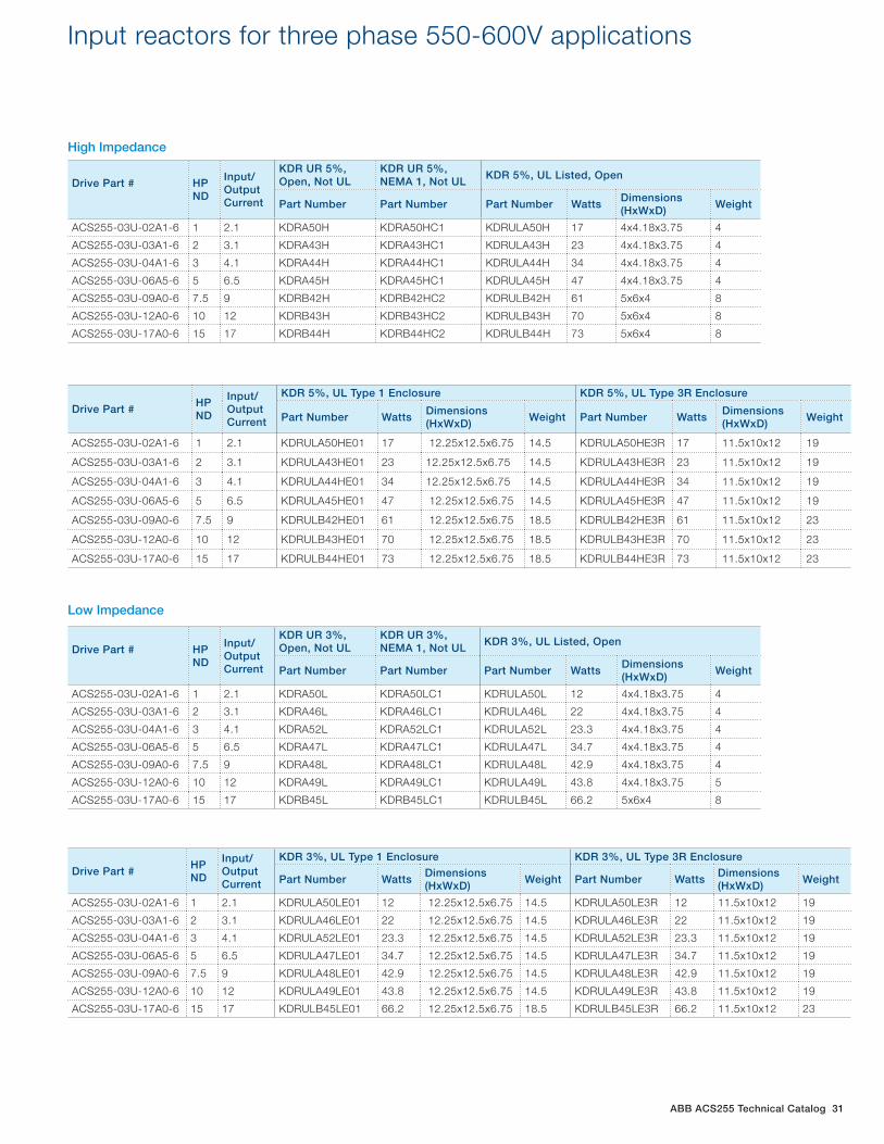
ABB ACS255 Technical Catalog 31
Drive Part # HP ND
Input/Output Current
KDR UR 5%, Open, Not UL
KDR UR 5%, NEMA 1, Not UL
KDR 5%, UL Listed, Open
Part Number Part Number Part Number WattsDimensions (HxWxD)
Weight
ACS255-03U-02A1-6 1 2.1 KDRA50H KDRA50HC1 KDRULA50H 17 4x4.18x3.75 4
ACS255-03U-03A1-6 2 3.1 KDRA43H KDRA43HC1 KDRULA43H 23 4x4.18x3.75 4
ACS255-03U-04A1-6 3 4.1 KDRA44H KDRA44HC1 KDRULA44H 34 4x4.18x3.75 4
ACS255-03U-06A5-6 5 6.5 KDRA45H KDRA45HC1 KDRULA45H 47 4x4.18x3.75 4
ACS255-03U-09A0-6 7.5 9 KDRB42H KDRB42HC2 KDRULB42H 61 5x6x4 8
ACS255-03U-12A0-6 10 12 KDRB43H KDRB43HC2 KDRULB43H 70 5x6x4 8
ACS255-03U-17A0-6 15 17 KDRB44H KDRB44HC2 KDRULB44H 73 5x6x4 8
Drive Part # HP ND
Input/Output Current
KDR 5%, UL Type 1 Enclosure KDR 5%, UL Type 3R Enclosure
Part Number WattsDimensions (HxWxD)
Weight Part Number WattsDimensions (HxWxD)
Weight
ACS255-03U-02A1-6 1 2.1 KDRULA50HE01 17 12.25x12.5x6.75 14.5 KDRULA50HE3R 17 11.5x10x12 19
ACS255-03U-03A1-6 2 3.1 KDRULA43HE01 23 12.25x12.5x6.75 14.5 KDRULA43HE3R 23 11.5x10x12 19
ACS255-03U-04A1-6 3 4.1 KDRULA44HE01 34 12.25x12.5x6.75 14.5 KDRULA44HE3R 34 11.5x10x12 19
ACS255-03U-06A5-6 5 6.5 KDRULA45HE01 47 12.25x12.5x6.75 14.5 KDRULA45HE3R 47 11.5x10x12 19
ACS255-03U-09A0-6 7.5 9 KDRULB42HE01 61 12.25x12.5x6.75 18.5 KDRULB42HE3R 61 11.5x10x12 23
ACS255-03U-12A0-6 10 12 KDRULB43HE01 70 12.25x12.5x6.75 18.5 KDRULB43HE3R 70 11.5x10x12 23
ACS255-03U-17A0-6 15 17 KDRULB44HE01 73 12.25x12.5x6.75 18.5 KDRULB44HE3R 73 11.5x10x12 23
Input reactors for three phase 550-600V applications
Drive Part # HP ND
Input/Output Current
KDR UR 3%, Open, Not UL
KDR UR 3%, NEMA 1, Not UL
KDR 3%, UL Listed, Open
Part Number Part Number Part Number WattsDimensions (HxWxD)
Weight
ACS255-03U-02A1-6 1 2.1 KDRA50L KDRA50LC1 KDRULA50L 12 4x4.18x3.75 4
ACS255-03U-03A1-6 2 3.1 KDRA46L KDRA46LC1 KDRULA46L 22 4x4.18x3.75 4
ACS255-03U-04A1-6 3 4.1 KDRA52L KDRA52LC1 KDRULA52L 23.3 4x4.18x3.75 4
ACS255-03U-06A5-6 5 6.5 KDRA47L KDRA47LC1 KDRULA47L 34.7 4x4.18x3.75 4
ACS255-03U-09A0-6 7.5 9 KDRA48L KDRA48LC1 KDRULA48L 42.9 4x4.18x3.75 4
ACS255-03U-12A0-6 10 12 KDRA49L KDRA49LC1 KDRULA49L 43.8 4x4.18x3.75 5
ACS255-03U-17A0-6 15 17 KDRB45L KDRB45LC1 KDRULB45L 66.2 5x6x4 8
Drive Part # HP ND
Input/Output Current
KDR 3%, UL Type 1 Enclosure KDR 3%, UL Type 3R Enclosure
Part Number WattsDimensions (HxWxD)
Weight Part Number WattsDimensions (HxWxD)
Weight
ACS255-03U-02A1-6 1 2.1 KDRULA50LE01 12 12.25x12.5x6.75 14.5 KDRULA50LE3R 12 11.5x10x12 19
ACS255-03U-03A1-6 2 3.1 KDRULA46LE01 22 12.25x12.5x6.75 14.5 KDRULA46LE3R 22 11.5x10x12 19
ACS255-03U-04A1-6 3 4.1 KDRULA52LE01 23.3 12.25x12.5x6.75 14.5 KDRULA52LE3R 23.3 11.5x10x12 19
ACS255-03U-06A5-6 5 6.5 KDRULA47LE01 34.7 12.25x12.5x6.75 14.5 KDRULA47LE3R 34.7 11.5x10x12 19
ACS255-03U-09A0-6 7.5 9 KDRULA48LE01 42.9 12.25x12.5x6.75 14.5 KDRULA48LE3R 42.9 11.5x10x12 19
ACS255-03U-12A0-6 10 12 KDRULA49LE01 43.8 12.25x12.5x6.75 14.5 KDRULA49LE3R 43.8 11.5x10x12 19
ACS255-03U-17A0-6 15 17 KDRULB45LE01 66.2 12.25x12.5x6.75 18.5 KDRULB45LE3R 66.2 11.5x10x12 23
High Impedance
Low Impedance
32 ABB ACS255 Technical Catalog
dv/dt output filters
Applications: V1k Output Filters provide motor protection by limiting voltage spikes to 1,000 volts, or below, for long motor cable applications. Greatly extends the life of the motor and cable for all applications up to 1000 feet. For multi-motor applications note that motor lead length is cumulative and the 1000 foot limit still applies. 30% reduction in common mode current enough, Features: UL Open, UL Type 1 and UL Type 3R construction with connection terminals.
Note: The drives internal EMC filter must remain disconnected when using these filters. When applying these output filters the drive output frequency is limited to 60Hz.
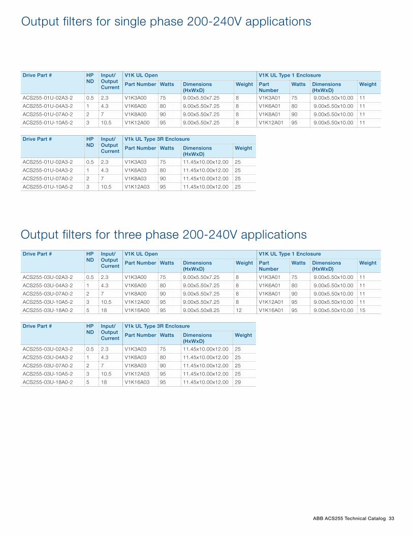
ABB ACS255 Technical Catalog 33
Drive Part # HP ND
Input/Output Current
V1K UL Open V1K UL Type 1 Enclosure
Part Number Watts Dimensions (HxWxD)
Weight Part Number
Watts Dimensions (HxWxD)
Weight
ACS255-01U-02A3-2 0.5 2.3 V1K3A00 75 9.00x5.50x7.25 8 V1K3A01 75 9.00x5.50x10.00 11
ACS255-01U-04A3-2 1 4.3 V1K6A00 80 9.00x5.50x7.25 8 V1K6A01 80 9.00x5.50x10.00 11
ACS255-01U-07A0-2 2 7 V1K8A00 90 9.00x5.50x7.25 8 V1K8A01 90 9.00x5.50x10.00 11
ACS255-01U-10A5-2 3 10.5 V1K12A00 95 9.00x5.50x7.25 8 V1K12A01 95 9.00x5.50x10.00 11
Output filters for single phase 200-240V applications
Drive Part # HP ND
Input/Output Current
V1k UL Type 3R Enclosure
Part Number Watts Dimensions (HxWxD)
Weight
ACS255-01U-02A3-2 0.5 2.3 V1K3A03 75 11.45x10.00x12.00 25
ACS255-01U-04A3-2 1 4.3 V1K6A03 80 11.45x10.00x12.00 25
ACS255-01U-07A0-2 2 7 V1K8A03 90 11.45x10.00x12.00 25
ACS255-01U-10A5-2 3 10.5 V1K12A03 95 11.45x10.00x12.00 25
Drive Part # HP ND
Input/Output Current
V1K UL Open V1K UL Type 1 Enclosure
Part Number Watts Dimensions (HxWxD)
Weight Part Number
Watts Dimensions (HxWxD)
Weight
ACS255-03U-02A3-2 0.5 2.3 V1K3A00 75 9.00x5.50x7.25 8 V1K3A01 75 9.00x5.50x10.00 11
ACS255-03U-04A3-2 1 4.3 V1K6A00 80 9.00x5.50x7.25 8 V1K6A01 80 9.00x5.50x10.00 11
ACS255-03U-07A0-2 2 7 V1K8A00 90 9.00x5.50x7.25 8 V1K8A01 90 9.00x5.50x10.00 11
ACS255-03U-10A5-2 3 10.5 V1K12A00 95 9.00x5.50x7.25 8 V1K12A01 95 9.00x5.50x10.00 11
ACS255-03U-18A0-2 5 18 V1K16A00 95 9.00x5.50x8.25 12 V1K16A01 95 9.00x5.50x10.00 15
Output filters for three phase 200-240V applications
Drive Part # HP ND
Input/Output Current
V1k UL Type 3R Enclosure
Part Number Watts Dimensions (HxWxD)
Weight
ACS255-03U-02A3-2 0.5 2.3 V1K3A03 75 11.45x10.00x12.00 25
ACS255-03U-04A3-2 1 4.3 V1K6A03 80 11.45x10.00x12.00 25
ACS255-03U-07A0-2 2 7 V1K8A03 90 11.45x10.00x12.00 25
ACS255-03U-10A5-2 3 10.5 V1K12A03 95 11.45x10.00x12.00 25
ACS255-03U-18A0-2 5 18 V1K16A03 95 11.45x10.00x12.00 29
34 ABB ACS255 Technical Catalog
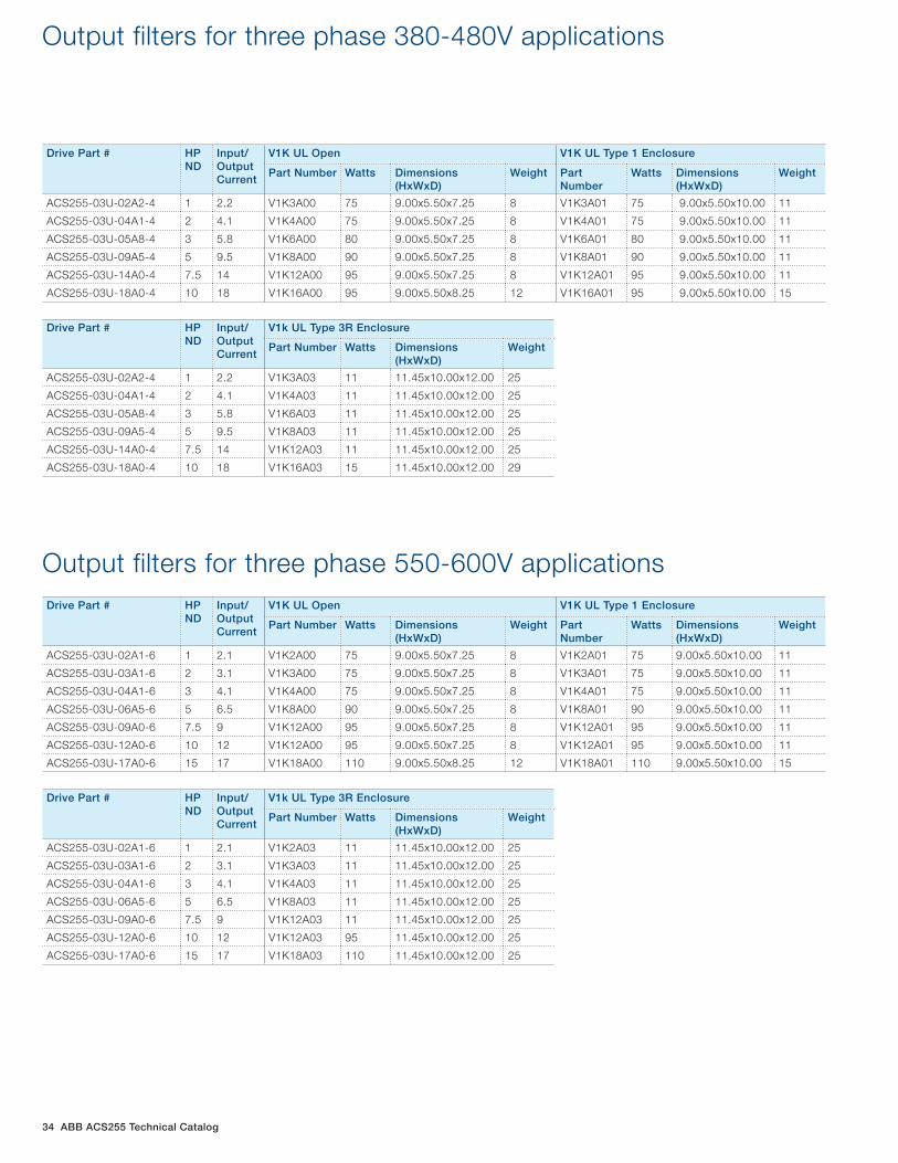
Drive Part # HP ND
Input/Output Current
V1K UL Open V1K UL Type 1 Enclosure
Part Number Watts Dimensions (HxWxD)
Weight Part Number
Watts Dimensions (HxWxD)
Weight
ACS255-03U-02A2-4 1 2.2 V1K3A00 75 9.00x5.50x7.25 8 V1K3A01 75 9.00x5.50x10.00 11
ACS255-03U-04A1-4 2 4.1 V1K4A00 75 9.00x5.50x7.25 8 V1K4A01 75 9.00x5.50x10.00 11
ACS255-03U-05A8-4 3 5.8 V1K6A00 80 9.00x5.50x7.25 8 V1K6A01 80 9.00x5.50x10.00 11
ACS255-03U-09A5-4 5 9.5 V1K8A00 90 9.00x5.50x7.25 8 V1K8A01 90 9.00x5.50x10.00 11
ACS255-03U-14A0-4 7.5 14 V1K12A00 95 9.00x5.50x7.25 8 V1K12A01 95 9.00x5.50x10.00 11
ACS255-03U-18A0-4 10 18 V1K16A00 95 9.00x5.50x8.25 12 V1K16A01 95 9.00x5.50x10.00 15
Output filters for three phase 380-480V applications
Drive Part # HP ND
Input/Output Current
V1k UL Type 3R Enclosure
Part Number Watts Dimensions (HxWxD)
Weight
ACS255-03U-02A2-4 1 2.2 V1K3A03 11 11.45x10.00x12.00 25
ACS255-03U-04A1-4 2 4.1 V1K4A03 11 11.45x10.00x12.00 25
ACS255-03U-05A8-4 3 5.8 V1K6A03 11 11.45x10.00x12.00 25
ACS255-03U-09A5-4 5 9.5 V1K8A03 11 11.45x10.00x12.00 25
ACS255-03U-14A0-4 7.5 14 V1K12A03 11 11.45x10.00x12.00 25
ACS255-03U-18A0-4 10 18 V1K16A03 15 11.45x10.00x12.00 29
Drive Part # HP ND
Input/Output Current
V1K UL Open V1K UL Type 1 Enclosure
Part Number Watts Dimensions (HxWxD)
Weight Part Number
Watts Dimensions (HxWxD)
Weight
ACS255-03U-02A1-6 1 2.1 V1K2A00 75 9.00x5.50x7.25 8 V1K2A01 75 9.00x5.50x10.00 11
ACS255-03U-03A1-6 2 3.1 V1K3A00 75 9.00x5.50x7.25 8 V1K3A01 75 9.00x5.50x10.00 11
ACS255-03U-04A1-6 3 4.1 V1K4A00 75 9.00x5.50x7.25 8 V1K4A01 75 9.00x5.50x10.00 11
ACS255-03U-06A5-6 5 6.5 V1K8A00 90 9.00x5.50x7.25 8 V1K8A01 90 9.00x5.50x10.00 11
ACS255-03U-09A0-6 7.5 9 V1K12A00 95 9.00x5.50x7.25 8 V1K12A01 95 9.00x5.50x10.00 11
ACS255-03U-12A0-6 10 12 V1K12A00 95 9.00x5.50x7.25 8 V1K12A01 95 9.00x5.50x10.00 11
ACS255-03U-17A0-6 15 17 V1K18A00 110 9.00x5.50x8.25 12 V1K18A01 110 9.00x5.50x10.00 15
Output filters for three phase 550-600V applications
Drive Part # HP ND
Input/Output Current
V1k UL Type 3R Enclosure
Part Number Watts Dimensions (HxWxD)
Weight
ACS255-03U-02A1-6 1 2.1 V1K2A03 11 11.45x10.00x12.00 25
ACS255-03U-03A1-6 2 3.1 V1K3A03 11 11.45x10.00x12.00 25
ACS255-03U-04A1-6 3 4.1 V1K4A03 11 11.45x10.00x12.00 25
ACS255-03U-06A5-6 5 6.5 V1K8A03 11 11.45x10.00x12.00 25
ACS255-03U-09A0-6 7.5 9 V1K12A03 11 11.45x10.00x12.00 25
ACS255-03U-12A0-6 10 12 V1K12A03 95 11.45x10.00x12.00 25
ACS255-03U-17A0-6 15 17 V1K18A03 110 11.45x10.00x12.00 25

ABB ACS255 Technical Catalog 35
ABB drive life cycle management model
Spare part, maintenance and repair services are available as long as materials can be obtained.
ABB cannot guarantee availability of life cycle services for technical reasons or within reasonable cost.
Limited life cycle servicesCaution! A drive entering the limited or obsolete phase has limited repair options. This may result in unpredictable process downtime. To avoid this possibility, the drive should be kept in the active or classic phase.
Limited ObsoleteActive Classic
The drive, with complete life cycle ser-vices, is available for purchase.
The drive, with complete life cycle services, is available for plant extensions.
Complete life cycle services
To ensure the availability of complete life cycle services, a drive must be in the active or classic phase. A drive can be kept in the active or classic phase by upgrading, retrofi t-ting or replacing.
Secure uptime throughout the drive life cycle
ABB follows a four-phase model for managing the life cycles of its drives. The life cycle phases are active, classic, limited and obsolete. Within each phase, every drive series has a defined set of services.
Examples of individual services are drive selection and di-mensioning, installation and commissioning, preventive and corrective maintenance, remote monitoring and intelligent diagnostics, technical support, upgrade and retrofit, replace-ment and recycling plus training and learning.
In the active phase the drive is in serial production. The drive, with complete life cycle services, is available for purchase. In the classic phase, the serial production of the drive has ended. The drive, with complete life cycle services, is avail-able for plant extensions.
In the limited phase, the drive is no longer available. The life cycle services are limited. Spare parts as well as maintenance and repair services are available as long as materials can be obtained.
In the obsolete phase, the drive is not available. ABB can-not guarantee availability of services for technical reasons or within reasonable cost.
To ensure the availability of complete life cycle services, ABB recommends that a drive is kept in the active or classic phase by upgrading, retrofitting or replacing.
In the classic phase ABB carries out an annual review for each drive life cycle plan. Should any changes to the availabil-ity or duration of the services be necessary, ABB gives a life cycle announcement indicating eventual change of life cycle phase and/or any change in the duration of services. In the limited phase, ABB issues a life cycle phase change an-nouncement, half a year prior to shifting the product into the obsolete phase.
Maximizing return on investmentThe four-phase life cycle management model provides cus-tomers with a transparent method for managing their invest-ment in drives. In each phase, customers clearly see what life cycle services are available, and more importantly, what services are not available. Decisions on upgrading, retrofitting or replacing drives can be made with confidence.