low voltage ac drives abb general purpose drives acs310 … · 2 abb general purpose drives acs310...
TRANSCRIPT
ABB general purpose drivesACS310 0.37 to 22 kW/0.5 to 30 hpCatalog
Low voltage AC drives

2 ABB general purpose drives ACS310 | Catalog
ACS310 drives for a wide range of variable torque applications
ABB general purpose drive, ACS310 is easy to select and easy to use. It is enough for most basic applications with no high overload demands. ACS310 is suitable for wide range of variable torque applications and simple machines.
The drive’s dedicated pump and fan features lower operating costs, boost energy efficiency and reduces CO2 emissions. Included amongs these features are built-in PID controllers and PFC (pump and fan control) that varies the drive’s performance in response to changes in pressure, flow or other external data.
Among the pre-programmed protection functions is pump cleaning. This prevents pump and pipe clogging by initiating a sequence of forward and reverse runs of the pump to clean the impeller.
Within pumping applications, energy savings can be up to 50 percent, compared to direct-on-line motor-driven systems that use mechanical flow control methods. The ABB general purpose drives provide built-in features for efficient energy management. Energy savings can be easily monitored using the built-in counters that display energy savings in kilowatt hours and saved carbon dioxide emissions. The savings can also be displayed in local currencies.
The compact design and uniform dimensions make cabinet mounting of the drive straightforward, thereby providing a fast and space saving installation. The ACS310 drives have an embedded Modbus interface for system monitoring that saves the cost of external fieldbus devices and enables to integrate the drives easily with PLC. When combined with preprogrammed application macros, an intuitive user interface and several assistant screens, installation time is further reduced while speeding up parameter setting and drive commissioning.
The ACS310 drives meet the needs of OEMs, logistical and technical distributors as well as the requirements of end users with pumping and ventilation applications. The drives are supported by one of the most extensive global sales and service networks with presence in over 100 countries.
Highlights − Powerful set of pump and fan features − Boosted energy efficiency − Tailored for cabinet installations − Clever drive commissioning assistants and convenient user
interface − Motor noice smoothing − Worldwide availability and service
Catalog | ABB general purpose drives ACS310 3
Contents
ACS310 drives for a wide range of variable torque applications..............................2
Essentials inside for basic applications .................................................................4
Typical applications ..............................................................................................6
How to select a drive ...........................................................................................7
Ratings and types ................................................................................................8
Technical data .....................................................................................................9
Dimensions and weights ....................................................................................10
Cooling.......... ...................................................................................................11
Fuses............ ....................................................................................................12
Control connections ...........................................................................................13
Control program example ...................................................................................14
Options........ .....................................................................................................16
Compact AC500-eCo PLC with ACS310.............................................................23
ABB product offering .........................................................................................24
Life cycle services ..............................................................................................26

4 ABB general purpose drives ACS310 | Catalog
Essentials inside for basic applications
ACS310 drives are simple and easy with all essentials included for applications with no high overload demand. Compact design with flexible mounting options saves space and installation time. Short menus and preprogrammed macros makes commissioning fast and easy. The drives powerful set of pump and fan features reduce mechanical stress and thus maintenance costs. Within pumping applications, energy savings of up to 50% can be achieved compared to direct-on-line motor-driven systems that use mechanical flow control methods. Wherever your machine is located, the local ABB will be there to support you and your clients.
Multipump and -fan controlOne drive controls several pumps or fans and eliminates the need for an external programmable logic controller. One pump is drive controlled and auxiliary pumps are on/off controlled. This reduces the motor stress and increase lifetime when auxiliary motors are driven according to the needed pump/fan capacity. Interlock function enables one motor to be disengaged from the mains supply while others continue operating in parallel.
Quick and easy commissioningPredefined I/O configurations for application macros and built-in assistants speed up commissioning of the drive, allowing you to concentrate on your business.
Robust design and qualityACS310 has coated control boards to increase robustness. Automatic fault reset to ensure uninterrupted operation. And protection against unstable supply networks.
Energy optimizerIntelligent drive control method improving the energy efficiency and system operation, especially while operating on partial centrifugal loads.
Load analyzerBuilt-in statistical tool that saves process data, such as current and torque values, which can be used to analyze and optimise the process. It can also be used for following system behaviour before and after any system modifications.
Compact and space saving designCompact size, with power range from 0.37 to 22 kW and flexible mounting possibilities ensure optimized installation in a wide range of applications, resulting in space and cost savings.
Catalog | ABB general purpose drives ACS310 5
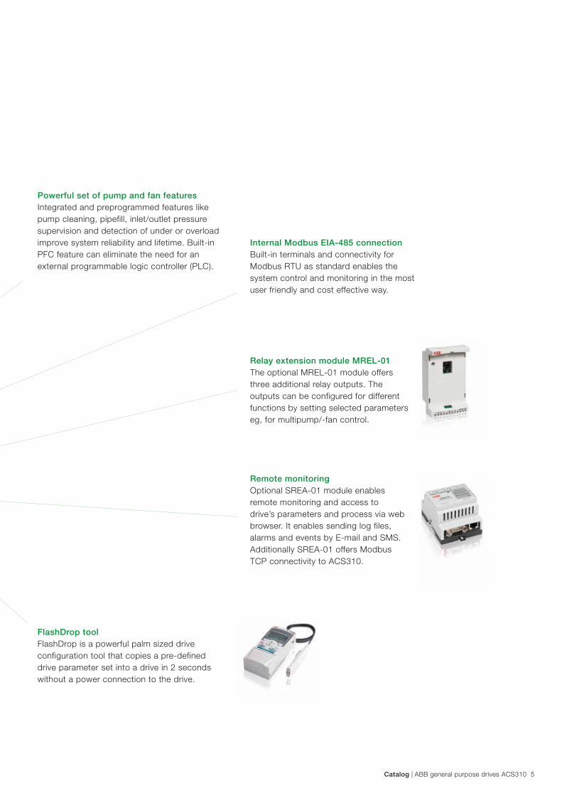
Powerful set of pump and fan featuresIntegrated and preprogrammed features like pump cleaning, pipefill, inlet/outlet pressure supervision and detection of under or overload improve system reliability and lifetime. Built-in PFC feature can eliminate the need for an external programmable logic controller (PLC).
FlashDrop toolFlashDrop is a powerful palm sized drive configuration tool that copies a pre-defined drive parameter set into a drive in 2 seconds without a power connection to the drive.
Remote monitoringOptional SREA-01 module enables remote monitoring and access to drive’s parameters and process via web browser. It enables sending log files, alarms and events by E-mail and SMS. Additionally SREA-01 offers Modbus TCP connectivity to ACS310.
Internal Modbus EIA-485 connectionBuilt-in terminals and connectivity for Modbus RTU as standard enables the system control and monitoring in the most user friendly and cost effective way.
Relay extension module MREL-01The optional MREL-01 module offers three additional relay outputs. The outputs can be configured for different functions by setting selected parameters eg, for multipump/-fan control.
6 ABB general purpose drives ACS310 | Catalog
Typical applications
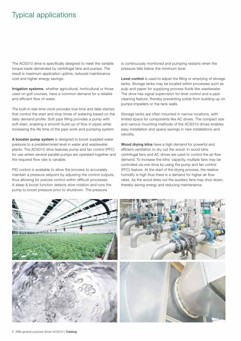
The ACS310 drive is specifically designed to meet the variable torque loads demanded by centrifugal fans and pumps. The result is maximum application uptime, reduced maintenance cost and higher energy savings.
Irrigation systems, whether agricultural, horticultural or those used on golf courses, have a common demand for a reliable and efficient flow of water.
The built-in real-time clock provides true time and date stamps that control the start and stop times of watering based on the daily demand profile. Soft pipe filling provides a pump with soft-start, enabling a smooth build-up of flow in pipes while increasing the life time of the pipe work and pumping system.
A booster pump system is designed to boost supplied water pressure to a predetermined level in water and wastewater plants. The ACS310 drive features pump and fan control (PFC) for use where several parallel pumps are operated together and the required flow rate is variable.
PID control is available to allow the process to accurately maintain a pressure setpoint by adjusting the control outputs, thus allowing for precise control within difficult processes. A sleep & boost function detects slow rotation and runs the pump to boost pressure prior to shutdown. The pressure
is continuously monitored and pumping restarts when the pressure falls below the minimum level.
Level control is used to adjust the filling or emptying of storage tanks. Storage tanks may be located within processes such as pulp and paper for supplying process fluids like wastewater. The drive has signal supervision for level control and a pipe cleaning feature, thereby preventing solids from building up on pumps impellers or the tank walls.
Storage tanks are often mounted in narrow locations, with limited space for components like AC drives. The compact size and various mounting methods of the ACS310 drives enables easy installation and space savings in new installations and retrofits.
Wood drying kilns have a high demand for powerful and efficient ventilation to dry out the wood. In wood kilns centrifugal fans and AC drives are used to control the air flow demand. To increase the kilns´ capacity, multiple fans may be controlled via one drive by using the pump and fan control (PFC) feature. At the start of the drying process, the relative humidity is high thus there is a demand for higher air flow rates. As the wood dries out the auxiliary fans may shut-down, thereby saving energy and reducing maintenance.
Catalog | ABB general purpose drives ACS310 7
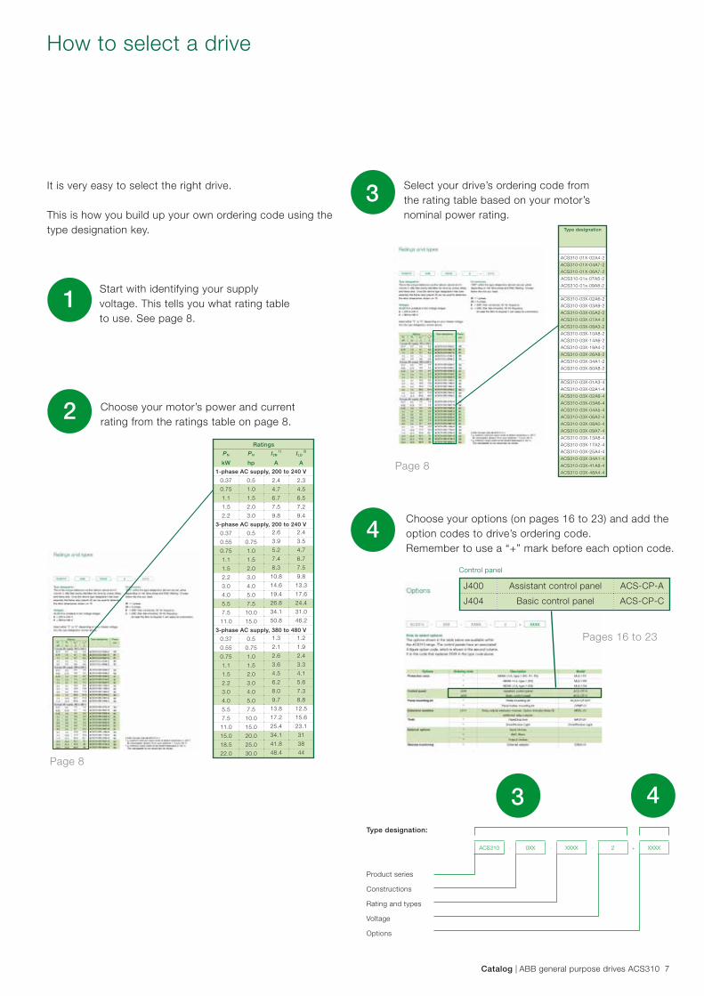
How to select a drive
It is very easy to select the right drive.
This is how you build up your own ordering code using the type designation key.
Start with identifying your supply voltage. This tells you what rating table to use. See page 8.
1
Choose your motor’s power and current rating from the ratings table on page 8.2
Product series
Constructions
Rating and types
Voltage
Options
Type designation:
4
43
ACS310 - 0XX - XXXX - 2 + XXXX
Choose your options (on pages 16 to 23) and add the option codes to drive’s ordering code. Remember to use a “+” mark before each option code.
Control panel
J400 Assistant control panel ACS-CP-A
J404 Basic control panel ACS-CP-C
Page 8
Ratings
PN
kW
PN
hp
I2N 1)
A
ILD 2)
A
1-phase AC supply, 200 to 240 V
0.37 0.5 2.4 2.3
0.75 1.0 4.7 4.5
1.1 1.5 6.7 6.5
1.5 2.0 7.5 7.2
2.2 3.0 9.8 9.4
3-phase AC supply, 200 to 240 V
0.37 0.5 2.6 2.4
0.55 0.75 3.9 3.5
0.75 1.0 5.2 4.7
1.1 1.5 7.4 6.7
1.5 2.0 8.3 7.5
2.2 3.0 10.8 9.8
3.0 4.0 14.6 13.3
4.0 5.0 19.4 17.6
5.5 7.5 26.8 24.4
7.5 10.0 34.1 31.0
11.0 15.0 50.8 46.2
3-phase AC supply, 380 to 480 V
0.37 0.5 1.3 1.2
0.55 0.75 2.1 1.9
0.75 1.0 2.6 2.4
1.1 1.5 3.6 3.3
1.5 2.0 4.5 4.1
2.2 3.0 6.2 5.6
3.0 4.0 8.0 7.3
4.0 5.0 9.7 8.8
5.5 7.5 13.8 12.5
7.5 10.0 17.2 15.6
11.0 15.0 25.4 23.1
15.0 20.0 34.1 31
18.5 25.0 41.8 38
22.0 30.0 48.4 44
Page 8
Select your drive’s ordering code from the rating table based on your motor’s nominal power rating.
3Type designation
ACS310-01X-02A4-2
ACS310-01X-04A7-2
ACS310-01X-06A7-2
ACS310-01x-07A5-2
ACS310-01x-09A8-2
ACS310-03X-02A6-2
ACS310-03X-03A9-2
ACS310-03X-05A2-2
ACS310-03X-07A4-2
ACS310-03X-08A3-2
ACS310-03X-10A8-2
ACS310-03X-14A6-2
ACS310-03X-19A4-2
ACS310-03X-26A8-2
ACS310-03X-34A1-2
ACS310-03X-50A8-2
ACS310-03X-01A3-4
ACS310-03X-02A1-4
ACS310-03X-02A6-4
ACS310-03X-03A6-4
ACS310-03X-04A5-4
ACS310-03X-06A2-4
ACS310-03X-08A0-4
ACS310-03X-09A7-4
ACS310-03X-13A8-4
ACS310-03X-17A2-4
ACS310-03X-25A4-4
ACS310-03X-34A1-4
ACS310-03X-41A8-4
ACS310-03X-48A4-4
Pages 16 to 23
8 ABB general purpose drives ACS310 | Catalog
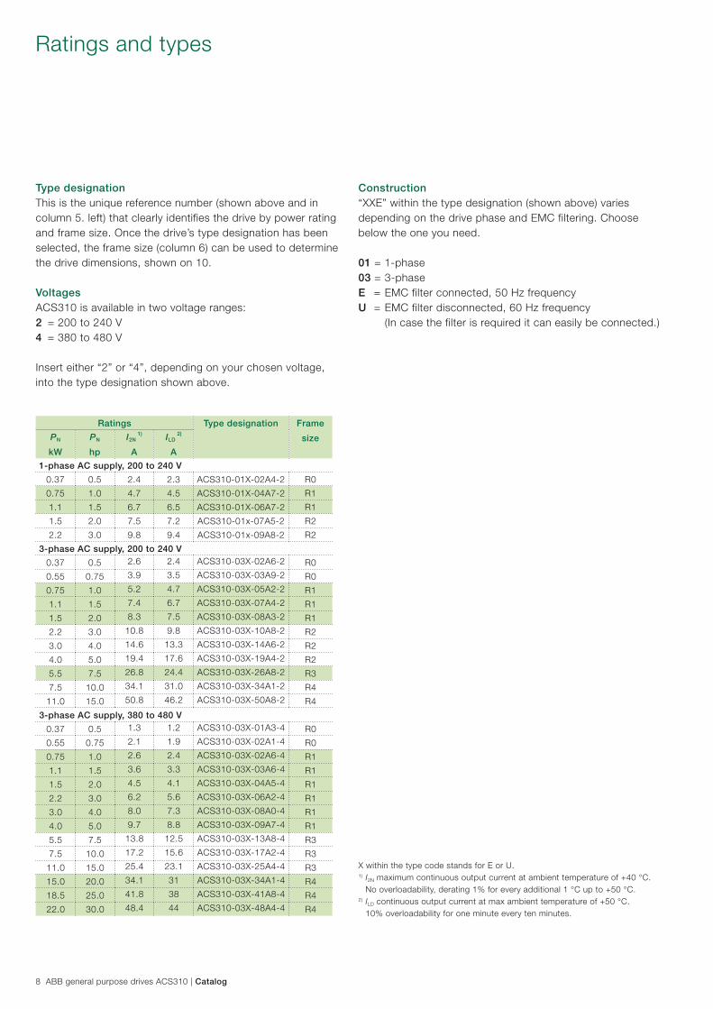
Ratings and types
Type designationThis is the unique reference number (shown above and in column 5. left) that clearly identifies the drive by power rating and frame size. Once the drive’s type designation has been selected, the frame size (column 6) can be used to determine the drive dimensions, shown on 10.
VoltagesACS310 is available in two voltage ranges: 2 = 200 to 240 V 4 = 380 to 480 V
Insert either “2” or “4”, depending on your chosen voltage, into the type designation shown above.
Construction“XXE” within the type designation (shown above) varies depending on the drive phase and EMC filtering. Choose below the one you need.
01 = 1-phase 03 = 3-phase E = EMC filter connected, 50 Hz frequency U = EMC filter disconnected, 60 Hz frequency (In case the filter is required it can easily be connected.)
Ratings Type designation Frame
sizePN
kW
PN
hp
I2N 1)
A
ILD 2)
A
1-phase AC supply, 200 to 240 V
0.37 0.5 2.4 2.3 ACS310-01X-02A4-2 R0
0.75 1.0 4.7 4.5 ACS310-01X-04A7-2 R1
1.1 1.5 6.7 6.5 ACS310-01X-06A7-2 R1
1.5 2.0 7.5 7.2 ACS310-01x-07A5-2 R2
2.2 3.0 9.8 9.4 ACS310-01x-09A8-2 R2
3-phase AC supply, 200 to 240 V
0.37 0.5 2.6 2.4 ACS310-03X-02A6-2 R0
0.55 0.75 3.9 3.5 ACS310-03X-03A9-2 R0
0.75 1.0 5.2 4.7 ACS310-03X-05A2-2 R1
1.1 1.5 7.4 6.7 ACS310-03X-07A4-2 R1
1.5 2.0 8.3 7.5 ACS310-03X-08A3-2 R1
2.2 3.0 10.8 9.8 ACS310-03X-10A8-2 R2
3.0 4.0 14.6 13.3 ACS310-03X-14A6-2 R2
4.0 5.0 19.4 17.6 ACS310-03X-19A4-2 R2
5.5 7.5 26.8 24.4 ACS310-03X-26A8-2 R3
7.5 10.0 34.1 31.0 ACS310-03X-34A1-2 R4
11.0 15.0 50.8 46.2 ACS310-03X-50A8-2 R4
3-phase AC supply, 380 to 480 V
0.37 0.5 1.3 1.2 ACS310-03X-01A3-4 R0
0.55 0.75 2.1 1.9 ACS310-03X-02A1-4 R0
0.75 1.0 2.6 2.4 ACS310-03X-02A6-4 R1
1.1 1.5 3.6 3.3 ACS310-03X-03A6-4 R1
1.5 2.0 4.5 4.1 ACS310-03X-04A5-4 R1
2.2 3.0 6.2 5.6 ACS310-03X-06A2-4 R1
3.0 4.0 8.0 7.3 ACS310-03X-08A0-4 R1
4.0 5.0 9.7 8.8 ACS310-03X-09A7-4 R1
5.5 7.5 13.8 12.5 ACS310-03X-13A8-4 R3
7.5 10.0 17.2 15.6 ACS310-03X-17A2-4 R3
11.0 15.0 25.4 23.1 ACS310-03X-25A4-4 R3
15.0 20.0 34.1 31 ACS310-03X-34A1-4 R4
18.5 25.0 41.8 38 ACS310-03X-41A8-4 R4
22.0 30.0 48.4 44 ACS310-03X-48A4-4 R4
X within the type code stands for E or U.1) I2N maximum continuous output current at ambient temperature of +40 °C. No overloadability, derating 1% for every additional 1 °C up to +50 °C.2) ILD continuous output current at max ambient temperature of +50 °C. 10% overloadability for one minute every ten minutes.
Catalog | ABB general purpose drives ACS310 9
Technical data
Mains connection
Voltage and power range
1-phase, 200 to 240 V ± 10%0.37 to 2.2 kW (0.5 to 3 hp) 3-phase, 200 to 240 V ± 10% 0.37 to 11 kW (0.5 to 15 hp) 3-phase, 380 to 480 V ± 10% 0.37 to 22 kW (0.5 to 30 hp)
Frequency 48 to 63 Hz
Motor connection
Voltage 3-phase, from 0 to Usupply
Frequency 0 to 500 Hz
Continuous loadingcapability
I2N maximum continuous output current at ambient temperature of +40 °C. No overloadability, derating 1% for every additional 1 °C up to 50 °C.
ILD continuous output current at max ambient temperature of +50 °C.10% overloadability for one minute every ten minutes. At start 1.6 x I2N for 2 s
Switching frequencyDefaultSelectable
4 kHz4 to 16 kHz with 4 kHz steps
Acceleration time 0.1 to 1800 s
Deceleration time 0.1 to 1800 s
Motor control method Scalar U/f
Environmental limits
Ambient temperature -10 to 50 oC (14 to 122 oF), no frost allowed
AltitudeOutput current Rated current available at 0 to 1000 m
(0 to 3281 ft) reduced by 1% per 100 m (328 ft) over 1000 to 2000 m (3281 to 6562 ft)
Relative humidity Lower than 95% (without condensation)
Degree of protection IP20/optional NEMA 1 enclosure
Enclosure colour NCS 1502-Y, RAL 9002, PMS 420 C
Contamination levels
Transportation
Storage
Operation
IEC721-3-3No conductive dust allowed Class 1C2 (chemical gases)Class 1S2 (solid particles)Class 2C2 (chemical gases) Class 2S2 (solid particles)Class 3C2 (chemical gases) Class 3S2 (solid particles)
Product compliance
Low Voltage Directive 2006/95/EC Machinery Directive 2006/42/EC EMC Directive 2004/108/EC Quality assurance system ISO 9001 Environmental system ISO 14001 UL, cUL, CE, C-Tick and GOST R approvalsRoHS compliant
Programmable control connections
Two analog inputsVoltage signalUnipolarBipolarCurrent signalUnipolarBipolarResolutionAccuracy
0 (2) to 10 V, Rin > 312 kΩ-10 to 10 V, Rin > 312 kΩ
0 (4) to 20 mA, Rin = 100 Ω-20 to 20 mA, Rin = 100 Ω0.1%± 1%
One analog output 0 (4) to 20 mA, load < 500 Ω
Auxiliary voltage 24 V DC ± 10%, max. 200 mA
Five digital inputs
Input impedance
12 to 24 V DC with internal or external supply, PNP and NPN, pulse train 0 to 16 kHz 2.4 kΩ
One relay outputTypeMaximum switching voltageMaximum switching currentMaximum continuous current
NO + NC250 V AC/30 V DC0.5 A/30 V DC; 5 A/230 V AC2 A rms
One digital outputTypeMaximum switching voltageMaximum switching currentFrequencyResolutionAccuracy
Transistor output30 V DC100 mA/30 V DC, short circuit10 Hz to 16 kHz1 Hz0.2%
Serial communication
FieldbusCable
TerminationIsolationTransfer rateCommunication typeProtocol
Modbus EIA-485, embeddedShielded twisted pair, impedance 100 to 150 ohmsDaisy-chained bus, without dropout linesBus interface isolated from drive1.2 to 76.8 kbit/sSerial, asynchronous, half duplexModbus
Chokes
AC input chokes External option For reducing THD in partial loads and to comply with EN/IEC 61000-3-12
AC output chokes External option To achieve longer motor cables
10 ABB general purpose drives ACS310 | Catalog
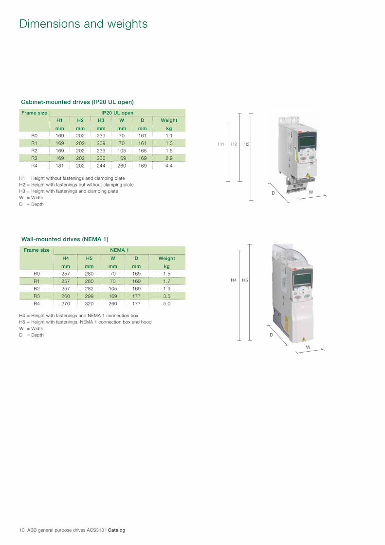
Dimensions and weights
H1 H2 H3
D W
H4 H5
W
D
H1 = Height without fastenings and clamping plateH2 = Height with fastenings but without clamping plateH3 = Height with fastenings and clamping plateW = WidthD = Depth
H4 = Height with fastenings and NEMA 1 connection boxH5 = Height with fastenings, NEMA 1 connection box and hoodW = WidthD = Depth
Cabinet-mounted drives (IP20 UL open)
Frame size IP20 UL open
H1
mm
H2
mm
H3
mm
W
mm
D
mm
Weight
kg
R0 169 202 239 70 161 1.1
R1 169 202 239 70 161 1.3
R2 169 202 239 105 165 1.5
R3 169 202 236 169 169 2.9
R4 181 202 244 260 169 4.4
Wall-mounted drives (NEMA 1)
Frame size NEMA 1
H4
mm
H5
mm
W
mm
D
mm
Weight
kg
R0 257 280 70 169 1.5
R1 257 280 70 169 1.7
R2 257 282 105 169 1.9
R3 260 299 169 177 3.5
R4 270 320 260 177 5.0
Catalog | ABB general purpose drives ACS310 11
Cooling
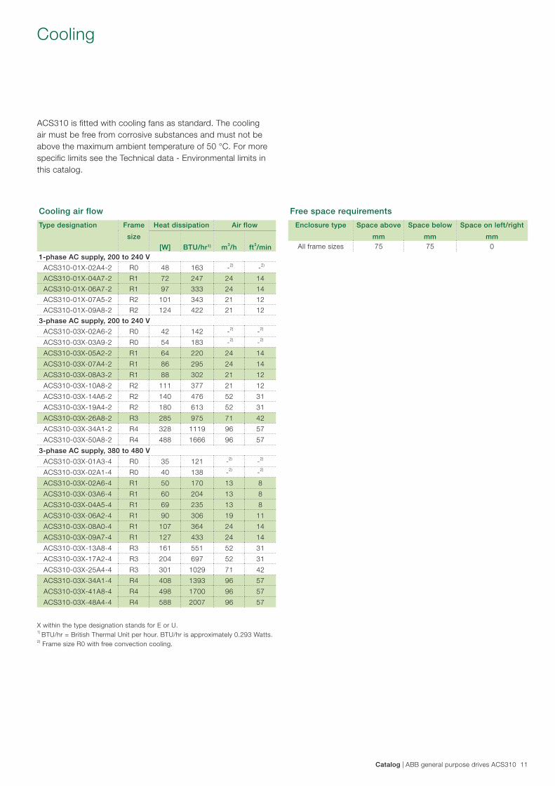
ACS310 is fitted with cooling fans as standard. The cooling air must be free from corrosive substances and must not be above the maximum ambient temperature of 50 °C. For more specific limits see the Technical data - Environmental limits in this catalog.
X within the type designation stands for E or U.1) BTU/hr = British Thermal Unit per hour. BTU/hr is approximately 0.293 Watts.
2) Frame size R0 with free convection cooling.
Free space requirements
Enclosure type Space above
mm
Space below
mm
Space on left/right
mmAll frame sizes 75 75 0
Cooling air flow
Type designation Frame
size
Heat dissipation Air flow
[W] BTU/hr1) m3/h ft3/min1-phase AC supply, 200 to 240 V
ACS310-01X-02A4-2 R0 48 163 -2) -2)
ACS310-01X-04A7-2 R1 72 247 24 14
ACS310-01X-06A7-2 R1 97 333 24 14
ACS310-01X-07A5-2 R2 101 343 21 12
ACS310-01X-09A8-2 R2 124 422 21 12
3-phase AC supply, 200 to 240 V
ACS310-03X-02A6-2 R0 42 142 -2) -2)
ACS310-03X-03A9-2 R0 54 183 -2) -2)
ACS310-03X-05A2-2 R1 64 220 24 14
ACS310-03X-07A4-2 R1 86 295 24 14
ACS310-03X-08A3-2 R1 88 302 21 12
ACS310-03X-10A8-2 R2 111 377 21 12
ACS310-03X-14A6-2 R2 140 476 52 31
ACS310-03X-19A4-2 R2 180 613 52 31
ACS310-03X-26A8-2 R3 285 975 71 42
ACS310-03X-34A1-2 R4 328 1119 96 57
ACS310-03X-50A8-2 R4 488 1666 96 57
3-phase AC supply, 380 to 480 V
ACS310-03X-01A3-4 R0 35 121 -2) -2)
ACS310-03X-02A1-4 R0 40 138 -2) -2)
ACS310-03X-02A6-4 R1 50 170 13 8
ACS310-03X-03A6-4 R1 60 204 13 8
ACS310-03X-04A5-4 R1 69 235 13 8
ACS310-03X-06A2-4 R1 90 306 19 11
ACS310-03X-08A0-4 R1 107 364 24 14
ACS310-03X-09A7-4 R1 127 433 24 14
ACS310-03X-13A8-4 R3 161 551 52 31
ACS310-03X-17A2-4 R3 204 697 52 31
ACS310-03X-25A4-4 R3 301 1029 71 42
ACS310-03X-34A1-4 R4 408 1393 96 57
ACS310-03X-41A8-4 R4 498 1700 96 57
ACS310-03X-48A4-4 R4 588 2007 96 57
12 ABB general purpose drives ACS310 | Catalog
Fuses
Reference voltage+10 V DC, max 10 mA
Analog input 2
Aux. voltage output+24 V DC, max. 200 mA
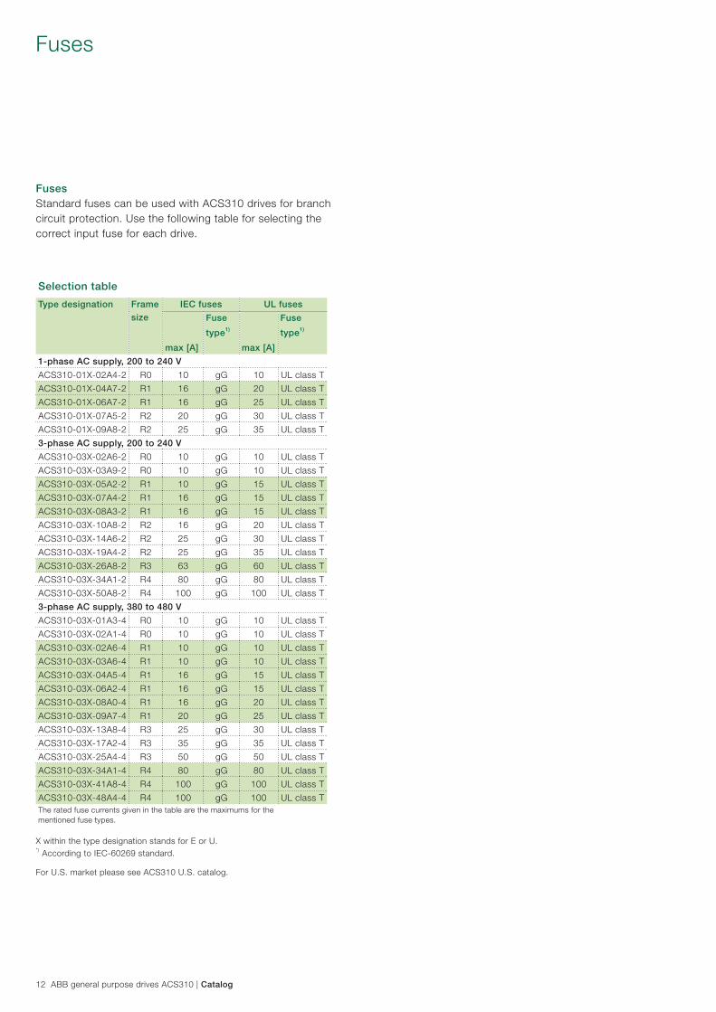
Selection table
Type designation Frame
size
IEC fuses UL fuses
max [A]
Fuse
type1)
max [A]
Fuse
type1)
1-phase AC supply, 200 to 240 V
ACS310-01X-02A4-2 R0 10 gG 10 UL class T
ACS310-01X-04A7-2 R1 16 gG 20 UL class T
ACS310-01X-06A7-2 R1 16 gG 25 UL class T
ACS310-01X-07A5-2 R2 20 gG 30 UL class T
ACS310-01X-09A8-2 R2 25 gG 35 UL class T
3-phase AC supply, 200 to 240 V
ACS310-03X-02A6-2 R0 10 gG 10 UL class T
ACS310-03X-03A9-2 R0 10 gG 10 UL class T
ACS310-03X-05A2-2 R1 10 gG 15 UL class T
ACS310-03X-07A4-2 R1 16 gG 15 UL class T
ACS310-03X-08A3-2 R1 16 gG 15 UL class T
ACS310-03X-10A8-2 R2 16 gG 20 UL class T
ACS310-03X-14A6-2 R2 25 gG 30 UL class T
ACS310-03X-19A4-2 R2 25 gG 35 UL class T
ACS310-03X-26A8-2 R3 63 gG 60 UL class T
ACS310-03X-34A1-2 R4 80 gG 80 UL class T
ACS310-03X-50A8-2 R4 100 gG 100 UL class T
3-phase AC supply, 380 to 480 V
ACS310-03X-01A3-4 R0 10 gG 10 UL class T
ACS310-03X-02A1-4 R0 10 gG 10 UL class T
ACS310-03X-02A6-4 R1 10 gG 10 UL class T
ACS310-03X-03A6-4 R1 10 gG 10 UL class T
ACS310-03X-04A5-4 R1 16 gG 15 UL class T
ACS310-03X-06A2-4 R1 16 gG 15 UL class T
ACS310-03X-08A0-4 R1 16 gG 20 UL class T
ACS310-03X-09A7-4 R1 20 gG 25 UL class T
ACS310-03X-13A8-4 R3 25 gG 30 UL class T
ACS310-03X-17A2-4 R3 35 gG 35 UL class T
ACS310-03X-25A4-4 R3 50 gG 50 UL class T
ACS310-03X-34A1-4 R4 80 gG 80 UL class T
ACS310-03X-41A8-4 R4 100 gG 100 UL class T
ACS310-03X-48A4-4 R4 100 gG 100 UL class TThe rated fuse currents given in the table are the maximums for thementioned fuse types.
FusesStandard fuses can be used with ACS310 drives for branch circuit protection. Use the following table for selecting the correct input fuse for each drive.
X within the type designation stands for E or U.*) According to IEC-60269 standard.
For U.S. market please see ACS310 U.S. catalog.

Typical I/O connections
Catalog | ABB general purpose drives ACS310 13
Control connections
Application macrosApplication macros are preprogrammed parameter sets. While starting up the drive, the user typically selects one of the macros that is best suited for the application. The diagram below gives an overview of ACS310 control connections and shows the default I/O connections for the ABB standard macro.
− ABB standard macro − 3-wire macro − Alternative macro − Motor potentiometer − Hand/auto macro − PID control macro − PFC control macro − SPFC control macro − Modbus application macro
SCR
AI1
GND
+10 V
AI2
GND
+24 V
GND
DCOM
DI1
DI2
DI3
DI4
DI5
PE
U1
V1
W1
AO
GND
ROCOM
RONC
RONO
DOSRC
DOOUT
DOGND
EMC
VAR
U2
V2
W2
Control panel(RJ-45)
PE
L1
L2
L3AC motor
M 3 ~
Analog output 0 to 20 mA
PROGRAMMABLE RELAYAND DIGITAL OUTPUTS
Relay output250 V AC/30 V DC/6 A
Digital/frequency output,PNP transistor type30 V DC, max. 100 mA
EMC filter grounding screw
Varistor grounding screw
Screen
8
Analog input 1 0 to 10 V
Reference voltage+10 V DC, max 10 mA
Analog input 2
Aux. voltage output+24 V DC, max. 200 mA
PROGRAMMABLE DIGITAL INPUTS
FlashDrop
Modbus RTU (EIA-485)
3-phase power supply,200 to 480 V AC
Input choke
Output choke
EMCfilter
AI1
AI2
mAV
Output relaymodule MREL-01
S1
1
2
3
4
5
6
9
10
11
12
13
14
15
16
23
24
25
26
SHIELD
B
A
GND_A
J7016
DI5 can also be used
as a frequency input
9
10
11
12
13
14
15
16
+24 V
GND
DCOM
DI1
DI2
DI3
DI4
DI5
DI configuration PNP connected (source) with external power supply
Const.speed 1
Fwd/Rev
Start/Stop
+ 24 V
0 V
ACS310: X1
DI configuration NPN connected (sink)
+24 V
GND
DCOM
DI1
DI2
DI3
DI4
DI5
9
10
11
12
13
14
15
16
ACS310: X1
Ramppair sel
Const.Speed 1
Fwd/Rev
Start/Stop
In addition to the standard macros, the user can create three user macros. The user macro allows the user to save the parameter settings for later use.
The diagram below gives an overview of ACS310 control connections. Please refer to the ACS310 user’s manual for more detailed information.
14 ABB general purpose drives ACS310 | Catalog
Control program example
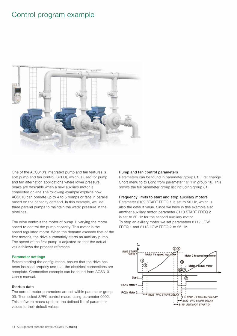
One of the ACS310’s integrated pump and fan features is soft pump and fan control (SPFC), which is used for pump and fan alternation applications where lower pressure peaks are desirable when a new auxiliary motor is connected on-line.The following example explains how ACS310 can operate up to 4 to 5 pumps or fans in parallel based on the capacity demand. In this example, we use three parallel pumps to maintain the water pressure in the pipelines.
The drive controls the motor of pump 1, varying the motor speed to control the pump capacity. This motor is the speed regulated motor. When the demand exceeds that of the first motor’s, the drive automaticly starts an auxiliary pump. The speed of the first pump is adjusted so that the actual value follows the process reference.
Parameter settingsBefore starting the configuration, ensure that the drive has been installed properly and that the electrical connections are complete. Connection example can be found from ACS310 User’s manual.
Startup data The correct motor parameters are set within parameter group 99. Then select SPFC control macro using parameter 9902. This software macro updates the defined list of parameter values to their default values.
Pump and fan control parameters Parameters can be found in parameter group 81. First change Short menu to to Long from parameter 1611 in group 16. This shows the full parameter group list including group 81.
Frequency limits to start and stop auxiliary motors Parameter 8109 START FREQ 1 is set to 50 Hz, which is also the default value. Since we have in this example also another auxiliary motor, parameter 8110 START FREQ 2 is set to 50 Hz for the second auxiliary motor. To stop an axiliary motor we set parameters 8112 LOW FREQ 1 and 8113 LOW FREQ 2 to 25 Hz.

Catalog | ABB general purpose drives ACS310 15
Auxiliary motors start and stop delay Delay stabilizes the contactors before starting or stopping a motor. Parameter 8115 AUX MOT START D is left to its default value 5 s. Parameter 8116 AUX MOT STOP D is left to it’s default value 20 s.
Number of auxiliary motors and motors in total Parameter 8117 NR OF AUX MOT is set to 2. Parameter 8127 MOTORS is set to 3.
Autochange functionality for SPFC The Autochange functionality for SPFC equalizes duty time between multiple motors, when auxiliary motors are not running. The time interval between motor changes is managed with parameter 8118.
Interlocks Interlock detects if any of the pumps are unavailable and starts the next available pump, when used. Set parameter 8120 INTERLOCKS to take input from DI3 in this example (depends of the number of interlocks and how thay are connected).
Default I/O settings
1. Hand: 0…10 V -> 0…50 Hz. PID/PFC: 0…10 V -> 0…100% PID setpoint.
2. 360 degree grounding under a clamp.
3. The signal source must be powered externally. See the manufacturer’s instructions.
Start delay for speed controlled motor Parameter 8122 PFC START DELAY is left to its default value 0,5 s.
Enabling pump and fan control Parameter 8123 PFC ENABLE is set to 3 (SPFC + AUTOCHANGE)
Relay configuration Relay configuration depends how many and how the motors are connected. Note! The macro SPFC already sets Transistor output parameter 1805 DO SIGNAL to PFC as an additional relay output which is connected. Parameter 1401 RELAY OUTPUT 1 is set to PFC Parameter 1402 RELAY OUTPUT 2 is set to PFC
16 ABB general purpose drives ACS310 | Catalog
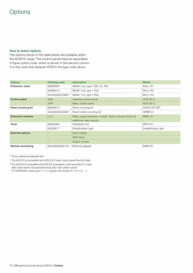
Options
How to select optionsThe options shown in the table below are available within the ACS310 range. The control panels have an associated 4-figure option code, which is shown in the second column. It is this code that replaces XXXX in the type code above.
*) To be ordered as separate item1) The ACS310 is compatible with ACS-CP-C basic control panel Rev M or later.2) The ACS310 is compatible with ACS-CP-A assistant control panel Rev E or later. (New panel series manufactured since 2007 with serial number XYYWWRXXXX, where year Y = 7 or greater and revision R = E, F, G, …)
Options Ordering code Description Model
Protection class 68566398 *) NEMA 1/UL type 1 (R0, R1, R2) MUL1-R1
68566410 *) NEMA 1/UL type 1 (R3) MUL1-R3
3AUA0000023888 *) NEMA 1/UL type 1 (R4) MUL1-R4
Control panel J400 Assistant control panel ACS-CP-A
J404 Basic control panel ACS-CP-C
Panel mounting kit 68294673 *) Panel mounting kit ACS/H-CP-EXT
3AUA0000013086 *) Panel holder mounting kit OPMP-01
Extension modules L511 Relay output extension module. Option includes three (3)
additional relay outputs.
MREL-01
Tools 68566380 *) FlashDrop tool MFDT-01
64532871 *) DriveWindow Light DriveWindow Light
External options *) Input chokes*) EMC filters*) Output chokes
Remote monitoring 3AUA0000039179 *) Ethernet adapter SREA-01

Catalog | ABB general purpose drives ACS310 17
OptionsInterface
User interface
Panel coverThe purpose of the panel cover is to protect the drive’s connection surfaces.The ACS310 drive is delivered with a panel cover as standard. In addition, there are two alternative control panels available as options.
Basic control panelThe basic control panel features a single line numeric display. The panel can be used to control the drive, set parameter values or copy them from one drive to another.
Assistant control panelThe assistant control panel features a multilingual alphanumeric display for easy drive programming. The control panel has various assistants and an built-in help function to guide the user. It includes a real time clock, which can be used during fault logging and in controlling the drive, such as at start/stop. The control panel can be used for copying parameters for back up or for downloading to another drive. A large graphical display and soft keys make it extremely easy to navigate.
Panel mounting kitsTo attach the control panel to the outside of a larger enclosure, two panel mounting kits are available. A simple and cost-efficient installation is possible with the ACS/H-CP-EXT kit, while the OPMP-01 kit provides a more user-friendly solution, including a panel platform that enables the panel to be removed in the same way as a drive-mounted panel. The panel mounting kits include all hardware required, including 3 meters extension cables and installation instructions.
Protection and installation
NEMA 1 kitThe NEMA 1 kit includes a connection box for finger protection, conduit tube installation, and a hood for protection against dirt and dust.
Terminal coverThe terminal cover is for protection of the I/O connections.
Clamping platesThe clamping plates are used for protection against electrical disturbances. The clamping plates with the clamps are included in the drive package as standard.
Panel cover (included as standard)
Basic control panel
Assistant control panel
Panel holder mounting kit OPMP-01
Clamping plates(included as standard)
Terminal cover(included as standard)
NEMA 1 kit

18 ABB general purpose drives ACS310 | Catalog
OptionsUser interfaces
Serial communicationThe embedded Modbus EIA-485 fieldbus brings connectivity to major automation systems. A single twisted pair cable avoids large amounts of conventional cabling, thereby reducing costs and increasing system reliability.
Modbus TCP to Modbus RTU gatewayAdditionally SREA-01 Ethernet adapter offers Modbus TCP to Modbus RTU gateway functionality which enables Modbus TCP connectivity to ACS310. Please refer to SREA-01 user’s guide for more detailed information.
Extension module
MREL-01ACS310 has one relay output as standard. The optional MREL-01 module offers three additional relay outputs. The outputs can be configured for different functions by setting selected parameters.
SREA-01 Ethernet adapterSREA-01 Ethernet adapter with remote monitoring access can send process data, data logs and event messages independently, without a PLC or a dedicated on-site computer. It has an internal web server for configuration and drive access. In remote locations without qualified service people on-site it is vital to be able to monitor the drive remotely. Monitoring and diagnostics routines can be easily implemented with ABB’s remote monitoring tool. The remote monitoring tool enables the connection of multiple drives to Ethernet, to collect operational data from the process and send the collected data to a central location for process monitoring and further analysis.
Extension module MREL-01 SREA-01 Ethernet adapter
FlashDrop connection
Fieldbus connection Modbus EIA-485
Analog I/O
Relay output
Digital output
Digital inputs
LEDs
Panel connector
EMC filter ground-ing screw (EMC)
Varistor ground-ing screw (VAR)
Removable clip for labeling
MREL-01 connector
Catalog | ABB general purpose drives ACS310 19
OptionsSoftware tools
A separate order line and type designation is required for any of these software tool options.
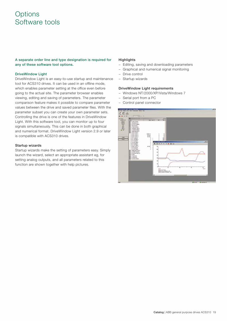
DriveWindow LightDriveWindow Light is an easy-to-use startup and maintenance tool for ACS310 drives. It can be used in an offline mode, which enables parameter setting at the office even before going to the actual site. The parameter browser enables viewing, editing and saving of parameters. The parameter comparison feature makes it possible to compare parameter values between the drive and saved parameter files. With the parameter subset you can create your own parameter sets. Controlling the drive is one of the features in DriveWindow Light. With this software tool, you can monitor up to four signals simultaneously. This can be done in both graphical and numerical format. DriveWindow Light version 2.9 or later is compatible with ACS310 drives.
Startup wizardsStartup wizards make the setting of parameters easy. Simply launch the wizard, select an appropriate assistant eg, for setting analog outputs, and all parameters related to this function are shown together with help pictures.
Highlights − Editing, saving and downloading parameters − Graphical and numerical signal monitoring − Drive control − Startup wizards
DriveWindow Light requirements − Windows NT/2000/XP/Vista/Windows 7 − Serial port from a PC − Control panel connector
20 ABB general purpose drives ACS310 | Catalog
A separate order line and type designation is required for any of these external options.
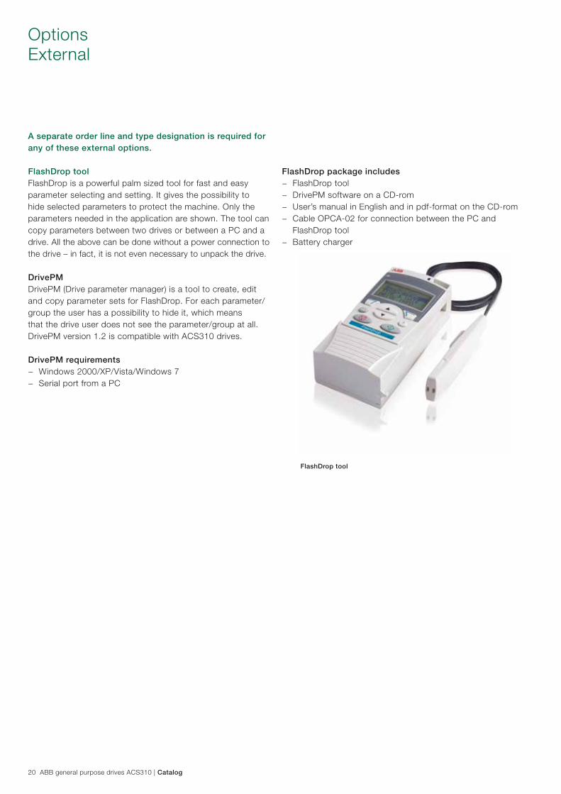
FlashDrop toolFlashDrop is a powerful palm sized tool for fast and easy parameter selecting and setting. It gives the possibility to hide selected parameters to protect the machine. Only the parameters needed in the application are shown. The tool can copy parameters between two drives or between a PC and a drive. All the above can be done without a power connection to the drive – in fact, it is not even necessary to unpack the drive.
DrivePMDrivePM (Drive parameter manager) is a tool to create, edit and copy parameter sets for FlashDrop. For each parameter/group the user has a possibility to hide it, which means that the drive user does not see the parameter/group at all. DrivePM version 1.2 is compatible with ACS310 drives.
DrivePM requirements − Windows 2000/XP/Vista/Windows 7 − Serial port from a PC
OptionsExternal
FlashDrop package includes − FlashDrop tool − DrivePM software on a CD-rom − User’s manual in English and in pdf-format on the CD-rom − Cable OPCA-02 for connection between the PC and
FlashDrop tool − Battery charger
FlashDrop tool
Catalog | ABB general purpose drives ACS310 21
OptionsExternal
A separate order line and type designation is required for any of these external options.
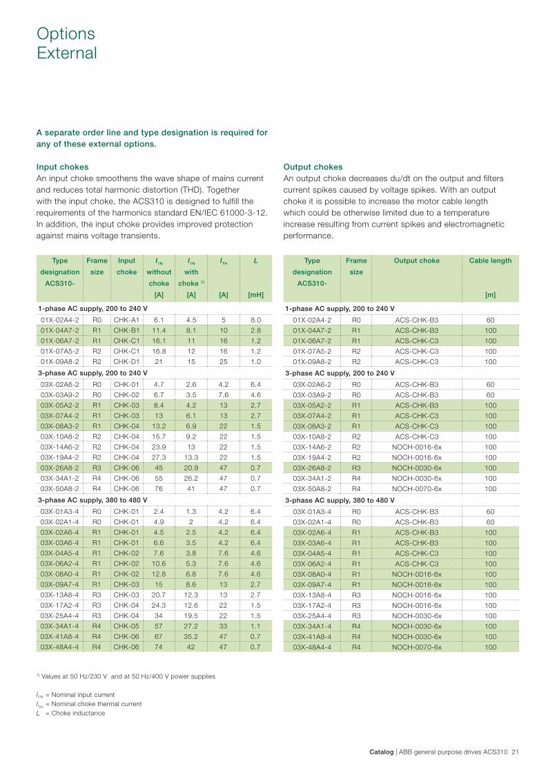
Input chokesAn input choke smoothens the wave shape of mains current and reduces total harmonic distortion (THD). Together with the input choke, the ACS310 is designed to fulfill the requirements of the harmonics standard EN/IEC 61000-3-12. In addition, the input choke provides improved protection against mains voltage transients.
Output chokesAn output choke decreases du/dt on the output and filters current spikes caused by voltage spikes. With an output choke it is possible to increase the motor cable length which could be otherwise limited due to a temperature increase resulting from current spikes and electromagnetic performance.
Type
designation
ACS310-
Frame
size
Output choke Cable length
[m]
1-phase AC supply, 200 to 240 V
01X-02A4-2 R0 ACS-CHK-B3 60
01X-04A7-2 R1 ACS-CHK-B3 100
01X-06A7-2 R1 ACS-CHK-C3 100
01X-07A5-2 R2 ACS-CHK-C3 100
01X-09A8-2 R2 ACS-CHK-C3 100
3-phase AC supply, 200 to 240 V
03X-02A6-2 R0 ACS-CHK-B3 60
03X-03A9-2 R0 ACS-CHK-B3 60
03X-05A2-2 R1 ACS-CHK-B3 100
03X-07A4-2 R1 ACS-CHK-C3 100
03X-08A3-2 R1 ACS-CHK-C3 100
03X-10A8-2 R2 ACS-CHK-C3 100
03X-14A6-2 R2 NOCH-0016-6x 100
03X-19A4-2 R2 NOCH-0016-6x 100
03X-26A8-2 R3 NOCH-0030-6x 100
03X-34A1-2 R4 NOCH-0030-6x 100
03X-50A8-2 R4 NOCH-0070-6x 100
3-phase AC supply, 380 to 480 V
03X-01A3-4 R0 ACS-CHK-B3 60
03X-02A1-4 R0 ACS-CHK-B3 60
03X-02A6-4 R1 ACS-CHK-B3 100
03X-03A6-4 R1 ACS-CHK-B3 100
03X-04A5-4 R1 ACS-CHK-C3 100
03X-06A2-4 R1 ACS-CHK-C3 100
03X-08A0-4 R1 NOCH-0016-6x 100
03X-09A7-4 R1 NOCH-0016-6x 100
03X-13A8-4 R3 NOCH-0016-6x 100
03X-17A2-4 R3 NOCH-0016-6x 100
03X-25A4-4 R3 NOCH-0030-6x 100
03X-34A1-4 R4 NOCH-0030-6x 100
03X-41A8-4 R4 NOCH-0030-6x 100
03X-48A4-4 R4 NOCH-0070-6x 100
Type
designation
ACS310-
Frame
size
Input
choke
I1N
without
choke
[A]
I1N
with
choke 1)
[A]
ITH
[A]
L
[mH]
1-phase AC supply, 200 to 240 V
01X-02A4-2 R0 CHK-A1 6.1 4.5 5 8.0
01X-04A7-2 R1 CHK-B1 11.4 8.1 10 2.8
01X-06A7-2 R1 CHK-C1 16.1 11 16 1.2
01X-07A5-2 R2 CHK-C1 16.8 12 16 1.2
01X-09A8-2 R2 CHK-D1 21 15 25 1.0
3-phase AC supply, 200 to 240 V
03X-02A6-2 R0 CHK-01 4.7 2.6 4.2 6.4
03X-03A9-2 R0 CHK-02 6.7 3.5 7.6 4.6
03X-05A2-2 R1 CHK-03 8.4 4.2 13 2.7
03X-07A4-2 R1 CHK-03 13 6.1 13 2.7
03X-08A3-2 R1 CHK-04 13.2 6.9 22 1.5
03X-10A8-2 R2 CHK-04 15.7 9.2 22 1.5
03X-14A6-2 R2 CHK-04 23.9 13 22 1.5
03X-19A4-2 R2 CHK-04 27.3 13.3 22 1.5
03X-26A8-2 R3 CHK-06 45 20.9 47 0.7
03X-34A1-2 R4 CHK-06 55 26.2 47 0.7
03X-50A8-2 R4 CHK-06 76 41 47 0.7
3-phase AC supply, 380 to 480 V
03X-01A3-4 R0 CHK-01 2.4 1.3 4.2 6.4
03X-02A1-4 R0 CHK-01 4.9 2 4.2 6.4
03X-02A6-4 R1 CHK-01 4.5 2.5 4.2 6.4
03X-03A6-4 R1 CHK-01 6.6 3.5 4.2 6.4
03X-04A5-4 R1 CHK-02 7.6 3.8 7.6 4.6
03X-06A2-4 R1 CHK-02 10.6 5.3 7.6 4.6
03X-08A0-4 R1 CHK-02 12.8 6.8 7.6 4.6
03X-09A7-4 R1 CHK-03 15 8.6 13 2.7
03X-13A8-4 R3 CHK-03 20.7 12.3 13 2.7
03X-17A2-4 R3 CHK-04 24.3 12.6 22 1.5
03X-25A4-4 R3 CHK-04 34 19.5 22 1.5
03X-34A1-4 R4 CHK-05 57 27.2 33 1.1
03X-41A8-4 R4 CHK-06 67 35.2 47 0.7
03X-48A4-4 R4 CHK-06 74 42 47 0.7
1) Values at 50 Hz/230 V and at 50 Hz/400 V power supplies I1N = Nominal input currentITH = Nominal choke thermal current L = Choke inductance
22 ABB general purpose drives ACS310 | Catalog
OptionsExternal
A separate order line and type designation is required for any of these external options.
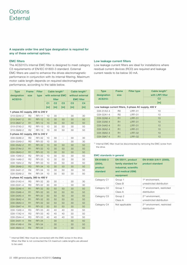
EMC filtersThe ACS310’s internal EMC filter is designed to meet category C3 requirements of EN/IEC 61800-3 standard. External EMC filters are used to enhance the drives electromagnetic performance in conjunction with its internal filtering. Maximum motor cable length depends on required electromagnetic performance, according to the table below.
Low leakage current filtersLow leakage current filters are ideal for installations where residual current devices (RCD) are required and leakage current needs to be below 30 mA.
Type
designation
ACS310-
Frame
size
Filter
type
Cable length1)
with external EMC
filter
Cable length1)
without external
EMC filter
C1
[m]
C2
[m]
C3
[m]
C3
[m]
C4
[m]
1-phase AC supply, 200 to 240 V
01X-02A4-2 R0 RFI-11 10 30 - 30 30
01X-04A7-2 R1 RFI-12 10 30 50 30 50
01X-06A7-2 R1 RFI-12 10 30 50 30 50
01X-07A5-2 R2 RFI-13 10 30 50 30 50
01X-09A8-2 R2 RFI-13 10 30 50 30 50
3-phase AC supply, 200 to 240 V
03X-02A6-2 R0 RFI-32 10 30 - 30 30
03X-03A9-2 R0 RFI-32 10 30 - 30 30
03X-05A2-2 R1 RFI-32 10 30 50 30 50
03X-07A4-2 R1 RFI-32 10 30 50 30 50
03X-08A3-2 R1 RFI-32 10 30 50 30 50
03X-10A8-2 R2 RFI-32 10 30 50 30 50
03X-14A6-2 R2 RFI-33 10 30 50 30 50
03X-19A4-2 R2 RFI-33 10 30 50 30 50
03X-26A8-2 R3 RFI-34 10 30 50 30 50
03X-34A1-2 R4 RFI-34 10 30 50 30 50
03X-50A8-2 R4 RFI-34 10 30 50 30 50
3-phase AC supply, 380 to 480 V
03X-01A3-4 R0 RFI-32 30 30 - 30 30
03X-02A1-4 R0 RFI-32 30 30 - 30 30
03X-02A6-4 R1 RFI-32 50 50 50 30 50
03X-03A6-4 R1 RFI-32 50 50 50 30 50
03X-04A5-4 R1 RFI-32 50 50 50 30 50
03X-06A2-4 R1 RFI-32 50 50 50 30 50
03X-08A0-4 R1 RFI-32 50 50 50 30 50
03X-09A7-4 R1 RFI-32 50 50 50 30 50
03X-13A8-4 R3 RFI-33 40 40 40 30 50
03X-17A2-4 R3 RFI-33 40 40 40 30 50
03X-25A4-4 R3 RFI-33 40 40 40 30 50
03X-34A1-4 R4 RFI-34 - 30 - 30 50
03X-41A8-4 R4 RFI-34 - 30 - 30 50
03X-48A4-4 R4 RFI-34 - 30 - 30 50
1) Internal EMC filter must be disconnected by removing the EMC screw from the drive.
Type
designation
ACS310-
Frame
size
Filter type Cable length1)
with LRFI filter
C2
[m]
Low leakage current filters, 3-phase AC supply, 400 V
03X-01A3-4 R0 LRFI-31 10
03X-02A1-4 R0 LRFI-31 10
03X-02A6-4 R1 LRFI-31 10
03X-03A6-4 R1 LRFI-31 10
03X-04A5-4 R1 LRFI-31 10
03X-06A2-4 R1 LRFI-31 10
03X-08A0-4 R1 LRFI-32 10
03X-09A7-4 R1 LRFI-32 10
EMC standards in general
EN 61800-3
(2004),
product
standard
EN 55011, product
family standard for
industrial, scientific
and medical (ISM)
equipment
EN 61800-3/A11 (2000),
product standard
Category C1 Group 1
Class B
1st environment,
unrestricted distribution
Category C2 Group 1
Class A
1st environment, restricted
distribution
Category C3 Group 2
Class A
2nd environment,
unrestricted distribution
Category C4 Not applicable 2nd environment, restricted
distribution
1) Internal EMC filter must be connected with the EMC screw in the drive. When the filter is not connected the C4 maximum cable lengths are allowed to be used.
Catalog | ABB general purpose drives ACS310 23
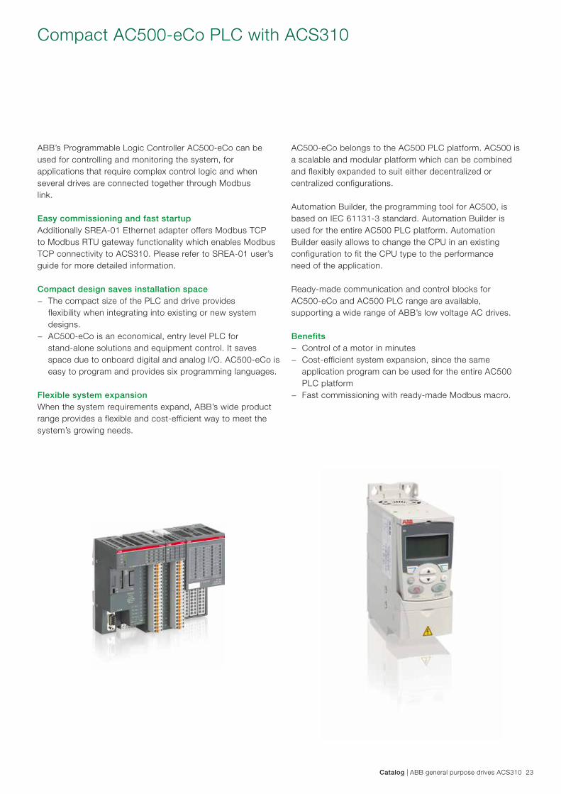
Compact AC500-eCo PLC with ACS310
ABB’s Programmable Logic Controller AC500-eCo can beused for controlling and monitoring the system, forapplications that require complex control logic and whenseveral drives are connected together through Modbuslink. Easy commissioning and fast startup Additionally SREA-01 Ethernet adapter offers Modbus TCP to Modbus RTU gateway functionality which enables Modbus TCP connectivity to ACS310. Please refer to SREA-01 user’s guide for more detailed information.
Compact design saves installation space − The compact size of the PLC and drive provides
flexibility when integrating into existing or new system designs.
− AC500-eCo is an economical, entry level PLC for stand-alone solutions and equipment control. It saves space due to onboard digital and analog I/O. AC500-eCo is easy to program and provides six programming languages.
Flexible system expansionWhen the system requirements expand, ABB’s wide product range provides a flexible and cost-efficient way to meet the system’s growing needs.
AC500-eCo belongs to the AC500 PLC platform. AC500 isa scalable and modular platform which can be combinedand flexibly expanded to suit either decentralized orcentralized configurations.
Automation Builder, the programming tool for AC500, isbased on IEC 61131-3 standard. Automation Builder isused for the entire AC500 PLC platform. AutomationBuilder easily allows to change the CPU in an existingconfiguration to fit the CPU type to the performanceneed of the application.
Ready-made communication and control blocks forAC500-eCo and AC500 PLC range are available,supporting a wide range of ABB’s low voltage AC drives.
Benefits − Control of a motor in minutes − Cost-efficient system expansion, since the same
application program can be used for the entire AC500 PLC platform
− Fast commissioning with ready-made Modbus macro.
24 ABB general purpose drives ACS310 | Catalog
ABB product offering
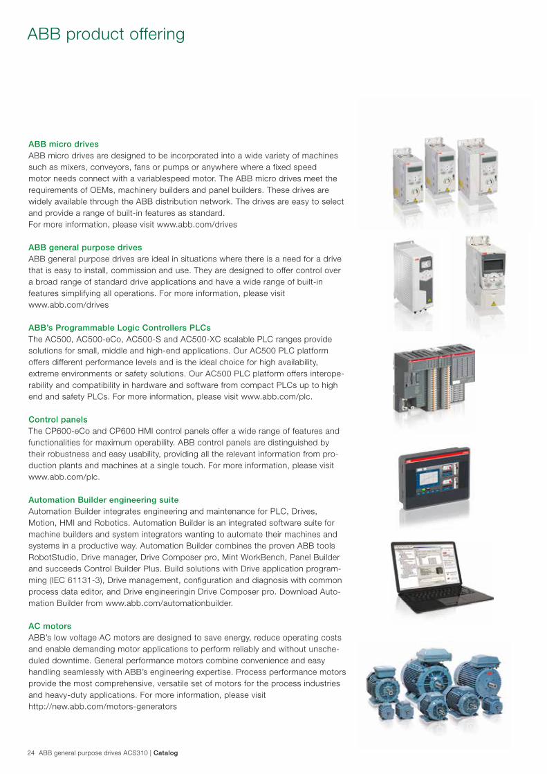
ABB micro drives ABB micro drives are designed to be incorporated into a wide variety of machines such as mixers, conveyors, fans or pumps or anywhere where a fixed speed motor needs connect with a variablespeed motor. The ABB micro drives meet the requirements of OEMs, machinery builders and panel builders. These drives are widely available through the ABB distribution network. The drives are easy to select and provide a range of built-in features as standard. For more information, please visit www.abb.com/drives
ABB general purpose drives ABB general purpose drives are ideal in situations where there is a need for a drive that is easy to install, commission and use. They are designed to offer control over a broad range of standard drive applications and have a wide range of built-in features simplifying all operations. For more information, please visit www.abb.com/drives
ABB’s Programmable Logic Controllers PLCs The AC500, AC500-eCo, AC500-S and AC500-XC scalable PLC ranges provide solutions for small, middle and high-end applications. Our AC500 PLC platform offers different performance levels and is the ideal choice for high availability, extreme environments or safety solutions. Our AC500 PLC platform offers interope-rability and compatibility in hardware and software from compact PLCs up to high end and safety PLCs. For more information, please visit www.abb.com/plc.
Control panels The CP600-eCo and CP600 HMI control panels offer a wide range of features and functionalities for maximum operability. ABB control panels are distinguished by their robustness and easy usability, providing all the relevant information from pro-duction plants and machines at a single touch. For more information, please visit www.abb.com/plc. Automation Builder engineering suite Automation Builder integrates engineering and maintenance for PLC, Drives, Motion, HMI and Robotics. Automation Builder is an integrated software suite for machine builders and system integrators wanting to automate their machines and systems in a productive way. Automation Builder combines the proven ABB tools RobotStudio, Drive manager, Drive Composer pro, Mint WorkBench, Panel Builder and succeeds Control Builder Plus. Build solutions with Drive application program-ming (IEC 61131-3), Drive management, configuration and diagnosis with common process data editor, and Drive engineeringin Drive Composer pro. Download Auto-mation Builder from www.abb.com/automationbuilder.
AC motors ABB’s low voltage AC motors are designed to save energy, reduce operating costs and enable demanding motor applications to perform reliably and without unsche-duled downtime. General performance motors combine convenience and easy handling seamlessly with ABB’s engineering expertise. Process performance motors provide the most comprehensive, versatile set of motors for the process industries and heavy-duty applications. For more information, please visit http://new.abb.com/motors-generators

Catalog | ABB general purpose drives ACS310 25

26 ABB general purpose drives ACS310 | Catalog
The future of your drives depends on the service you choose. Whatever you choose, it should be a well-informed decision. No guesswork. We have the expertise and experience to help you find and implement the right service for your drive equipment. You can start by asking yourself these two critical questions:
− Why should my drive be serviced? − What would my optimal service options be?
From here, you have our guidance and full support along the course you take, throughout the entire lifetime of your drives.
Drives serviceYour choice, your future
Service to match your needs
Your choice, your business efficiencyABB Drive Care agreement lets you focus on your core business. A selection of predefined service options matching your needs provides optimal, more reliable performance, extended drive lifetime and improved cost control. So you can reduce the risk of unplanned downtime and find it easier to budget for maintenance.
We can help you more by knowing where you are!Register your drive at www.abb.com/drivereg for extended warranty options and other benefits.
Your service needs depend on your operation, life cycle of your equipment and business priorities. We have identified our customers’ four most common needs and defined service options to satisfy them. What is your choice to keep your drives at peak performance?
Is rapid response a key consideration? If your drives require immediate action, our global network is at your service.
Example services include:
Technical Support
On-site Repair
Remote Support
Response time agreements
Training
Need to extend your assets’ lifetime?Maximize your drive’s lifetime with our services.
Example services include:
Life Cycle Assessment
Upgrades, Retrofits and Modernization
Replacement, Disposal and Recycling
Is performance most critical to your operation? Get optimal performance out of your machinery and systems.
Example services include:
Advanced services
Engineering and Consulting
Inspection and Diagnostics
Upgrades, Retrofits and Modernization
Workshop Repair
Tailored services
Is uptime your priority?Keep your drives running with precisely planned and executed maintenance.
Example services include:
Life Cycle Assessment
Installation and Commissioning
Spare Parts
Preventive Maintenance
Reconditioning
ABB Drive Care agreement
Drive Exchange
Performance improvement
Operational efficiency
Rapid response
24
Life cycle management
Catalog | ABB general purpose drives ACS310 27
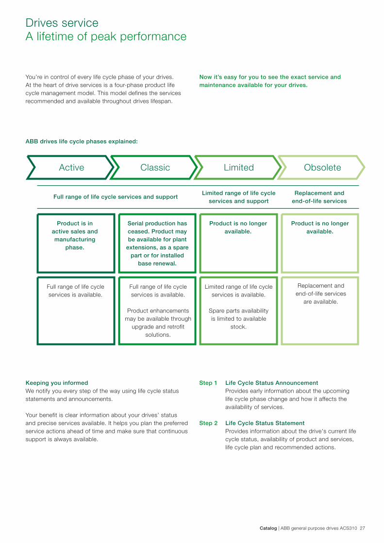
Drives serviceA lifetime of peak performance
You’re in control of every life cycle phase of your drives. At the heart of drive services is a four-phase product life cycle management model. This model defines the services recommended and available throughout drives lifespan.
Now it’s easy for you to see the exact service and maintenance available for your drives.
Keeping you informedWe notify you every step of the way using life cycle status statements and announcements.
Your benefit is clear information about your drives’ status and precise services available. It helps you plan the preferred service actions ahead of time and make sure that continuous support is always available.
Product is in active sales and manufacturing
phase.
Full range of life cycle services is available.
Full range of life cycle services is available.
Product enhancements
may be available through upgrade and retrofit
solutions.
Limited range of life cycle services is available.
Spare parts availability is limited to available
stock.
Product is no longer available.
Product is no longer available.
Active Classic Limited Obsolete
ABB drives life cycle phases explained:
Full range of life cycle services and supportLimited range of life cycle
services and supportReplacement and
end-of-life services
Serial production has ceased. Product may be available for plant
extensions, as a spare part or for installed
base renewal.
Replacement and end-of-life services
are available.
Life Cycle Status AnnouncementProvides early information about the upcoming life cycle phase change and how it affects the availability of services.
Life Cycle Status StatementProvides information about the drive's current life cycle status, availability of product and services, life cycle plan and recommended actions.
Step 1
Step 2

Contact us
3AU
A00
0005
1082
RE
V G
EN
16.
5.20
16 *
1313
9© Copyright 2016 ABB. All rights reserved. Specifications subject to change without notice.
For more information please contact your local ABB representative or visit: www.abb.com/driveswww.abb.com/drivespartners www.abb.com/plcwww.abb.com/automationbuilder
ACS310 how-to video: