low noise solutions for turbine bypass to air-cooled...
TRANSCRIPT
ASME
Low Noise Solutions for Turbine Bypass to Air-Cooled Condensers

Low
Nois
e S
olu
tion
s fo
r Tu
rbin
e B
ypas
s to
Air
-Coole
d C
on
den
sers
Figure 1: ACC duct on a large combined cycle power station. The duct is long, large, and uninsulated.
Figure 2: Noise at the surface of the duct can propagate to nearby communities.
2 Air-Cooled Condenser Plants Demand Low- Noise Bypass Equipment
Introduction
In a power plant with an air-cooled condenser (ACC), steam is
carried from the steam turbine exhaust to the condenser via a
large, thin wall, uninsulated duct. Noise sources that discharge into
the ACC duct have much less attenuation than in a water-cooled
condenser. The ACC duct is typically external to the turbine building
and has a very large surface area. High noise levels at the ACC duct
surface can generate unacceptable noise levels at the plant boundary
and in neighboring communities.
This problem is especially important in combined cycle power
stations. Combined cycle power stations have 100% turbine bypass
systems. The combined steam flow and desuperheater cooling flow
from the bypass system discharges nearly 50% more mass flow
into the duct than the steam turbine, and at a higher enthalpy. This
large amount of mass flow is discharged into a dump device that is
much smaller than the steam turbine exhaust, concentrating noise
energy into a very small area. Single-stage control valves and dump
elements can generate external noise levels in excess of 130 dBA
at a distance of 1m from the ACC duct surface, and 75 dBA up to
a kilometer from the plant. With many combined cycle plants on
daily cycling, start-up noise can become a severe constraint in plant
operation.
Combined cycle power stations are also relatively compact, and are
much more likely to be sited in a sensitive environment than a large
coal-fired boiler. Plants with excessive noise levels may face financial
penalties and, in some cases, suspension of plant operation. Due to
the large size of the ACC duct, traditional noise treatment methods
like acoustic enclosures or insulation are impractical or insufficient.
The source noise must be treated in order to meet plant noise
requirements.
Complete Noise and Bypass System Specification
It is important to establish correct and complete noise specifications
for ACC systems. Almost all plants establish near field sound
pressure levels of 90 dBA for insulated pipes in order to provide a
safe working environment. In ACC plants the far field requirements
will usually dictate the near field requirements. Far field
requirements of 60 dBA at 400 feet from duct may require near
field requirements of 85 dBA at 3 feet from duct. Since the duct is
not insulated, the noise performance of the bypass system must be
significantly lower than is applied in conventional power stations.
Figure 3: Compact dump element with elliptical or “fish mouth” discharge. These designs generate large noise at the surface of the ACC duct.

Low
Noise S
olu
tion
s for Tu
rbin
e Byp
ass to A
ir-Cooled
Con
den
sers3
In a bypass system, there will be a variety of service conditions
corresponding to the different plant operating modes. Typical
operating modes include full-load trip, duct firing, cold start, and
hot start. The duration and frequency of these operation modes
varies significantly, and the far field noise requirements for the plant
may be different for each operating mode. The noise requirements
and operating conditions for the bypass system must be completly
defined and reviewed to insure that plant noise requirements are
met. The noise requirements and operating conditions also have
a significant effect on the cost, size, and complexity of the bypass
system design.
Sources of Noise in ACC Systems
The noise from the bypass system comes from two primary sources,
the steam bypass control valve and the final dump element that
discharges all steam flow and spraywater flow into the ACC duct.
The sound power and peak frequency of each source must be
controlled in order to reduce overall system noise.
The dominant source in large power stations is the final dump
element in the bypass to condenser systems. The most common
dump element designs feature a large array of 12 mm or 6 mm
drilled holes, densely packed on a flat circular plate, an elliptical
fish mouth device, or a dump tube (Figures 3 and 4). These designs
can generate noise levels in excess of 130 dBA at a distance of 1m
from the ACC duct surface. The large amount of concentrated sound
power creates vibration that can cause cracks in the duct walls and
dump element mounting ring (Figure 5).
The noise generated by the dump element at the ACC duct surface
can be significantly reduced by using a combination of smaller
orifice sizes and multi-stage pressure reduction. Smaller orifice
sizes shift the peak frequency of jets discharging from the dump
element. Multi-stage pressure reduction reduces the discharge
velocity of jets on the surface of the dump element. In some cases
we must apply both approaches in order to achieve the necessary
noise performance. DRAG® multi-stage technology provides the best
possible noise performance in bypass to condenser applications
(Figure 6).
Total ACC Noise is the Result of Many Individual Noise Sources
Figure 4: Compact dump tube.
Figure 5: Cracks at a lifting hub on the surface of an ACC duct. The cracks were generated by the high power, low frequency jet generated by a compact dump element.
Figure 6: Comparison of the sound power and frequency spectrum for three dump element technologies. The DRAG® resistor combines a multi-stage pressure letdown design with frequency shifting to reduce overall system noise.
Noise vs Freqency, Drag Resistor and Dump Tubes
40.0
60.0
80.0
100.0
120.0
140.0
160.0
10 100 1000 10000 100000Frequency, Hz
Soun
d Po
wer
, dB
DRAG Resistor Low Noise Dump Tube Compact Dump Tube
Low
Nois
e S
olu
tion
s fo
r Tu
rbin
e B
ypas
s to
Air
-Coole
d C
on
den
sers
4
Total System Design
The overlay on pages 8 and 9 shows an illustration of
a typical bypass system. The bypass system includes
many elements, including the steam bypass control
valve, diffusers, one or more desuperheaters, and the
final dump element. The total system design must be
reviewed to meet noise requirements. Noise sources
upstream of the final dump element will transmit
downstream into the ACC duct. The steam bypass
control valve and diffusers may require multi-stage
technology.
In bypass to condenser applications the temperature
after desuperheating is saturated because typically
Low Noise Performance Requires a Total System Solution
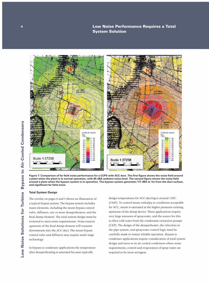
Figure 7: Comparison of far field noise performance for a CCPS with ACC duct. The first figure shows the noise field around a plant when the plant is in normal operation, with 85 dBA ambient noise level. The second figure shows the noise field around a plant when the bypass system is in operation. The bypass system generates 117 dBA at 1m from the duct surface, and significant far field noise.
design temperatures for ACC ducting is around 120C
(250F). To control steam enthalpy to conditions acceptable
for ACC, steam is saturated at the higher pressures existing
upstream of the dump device. These applications require
very large amounts of spraywater, and the source for this
is often cold water from the condensate extraction pumps
(CEP). The design of the desuperheater, the velocities in
the pipe system, and spraywater control logic must be
carefully made to ensure reliable operation. Bypass to
condenser applications require consideration of total system
design and more so in air-cooled condensers where noise
requirements, control and evaporation of spray water are
required to be more stringent.
Low
Noise S
olu
tion
s for Tu
rbin
e Byp
ass to A
ir-Cooled
Con
den
sers5DRAG® Multi-Stage Technology
Benefits of DRAG® Multi-Stage Technology
CCI designs and manufactures a unique technology that provides
the best possible noise performance. This technology is available for
the steam bypass valve trim and for the final dump element.
The DRAG® design divides the flow through the control valve or
dump element into hundreds of multi-path multi-stage streams.
Each flow path consists of a specific number of right angle turns.
These flow paths establish a tortuous path, and each turn reduces
the pressure of the flowing medium. The pressure drop on the last
stage of a DRAG® disk is many times less than the pressure drop
on a single-stage orifice. With this technology we can specify the
necessary number of stages to achieve plant noise requirements. CCI
can provide this technology both within the control valve trim and
in the final dump element in the ACC duct.
The DRAG® resistor provides additional benefits in bypass to
condenser applications. The steam entering the condenser dump
element is typically wet steam, with 95% to 97% quality. Multi-
Stage conventional drilled hole dump devices are not recommended
as they will gradually be eroded by impinging high velocity wet
steam jets from the individual stages onto the material (diffuser) of
the next stage. DRAG® velocity control protects the dump element
from wet steam erosion, and stainless steel construction of the disks
ensures long service life. The DRAG® resistor also gives much greater
pipe and system design flexibility. The DRAG® resistor can provide
lower system noise with much higher inlet pressures. This gives
plant designers the flexibility to specify higher pressures and smaller
pipes sizes for the intermediate pipe between the bypass valve
and dump element. It also gives the bypass system designer more
flexibility to optimize system velocities for improved noise control
and desuperheating.
Special DRAG Hex Resistors
The DRAG® resistor disks for bypass to condenser applications
are assembled from hundreds of disk strips. The disk strips are
held together using a series of pins that cross link the strips. This
unique design provides the durability and toughness required to
withstand the dynamic forces that act on the resistor during a full-
load trip. The disks are manufactured from 12 chrome stainless
steel, which resists the thermal gradients and erosion from steam
quality variations associated with condenser discharge systems. The
disks use a special version of the DRAG® flow path that has been
optimized for discharge to the condenser applications.
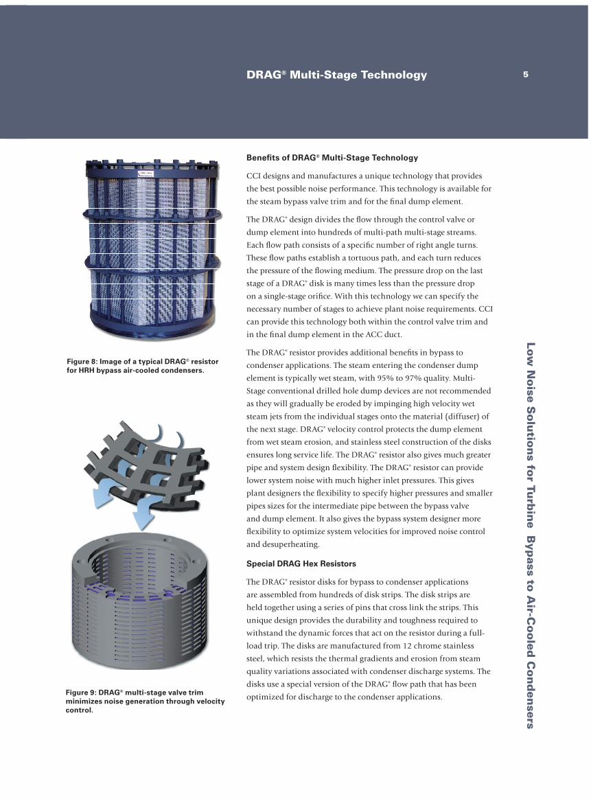
Figure 8: Image of a typical DRAG® resistor for HRH bypass air-cooled condensers.
Figure 9: DRAG® multi-stage valve trim minimizes noise generation through velocity control.

Low
Nois
e S
olu
tion
s fo
r Tu
rbin
e B
ypas
s to
Air
-Coole
d C
on
den
sers
6 DRAG® Resistor – Dump Element Incorporating DRAG® Technology
Table 1: Standard DRAG® Resistor Configurations
Notes:The size of the DRAG® resistor may require the use of a bell housing to avoid excessive ACC duct blockage. - The bell housing diameters above assume that the DRAG® resistor is 100% contained in the bell housing and assumes an ACC duct pressure of 2 psia (.13 bara), and an enthalpy of 1170 BTU/lbm ( 2720 kJ/kg). - The bell housing diameter may be reduced if the DRAG® resistor is only partially contained.
HRH Bypass Steam Flow (excl spray water)
NominalDiameter (D
N)
Resistor Height (HR)
Max Resistor Diameter (DMAX)
Bell Housing Diameter
100000 - 300000 lbm/hr(45450 - 136360 mt/hr)
24” (61 cm)
33” (82 cm)
40” (102 cm)70” – 100”
(180 – 254 cm)
39” (99 cm)
47” (120 cm)
54” (137 cm)
175000 - 450000 lbm/hr(79545 - 204550 mt/hr)
30” (76 cm)
40” (102 cm)
44” (112 cm)85” – 125”
(216 – 318 cm)
48” (122 cm)
55” (140 cm
64” (163 cm)
300000 - 675000 lbm/hr(136360 - 306820 mt/hr)
36” (91 cm)
49” (125 cm)
51” (130 cm)105” – 150”
(267 – 381 cm)
57” (145 cm)
66” (168 cm)
76” (193 cm)
450000 - 900000 lbm/hr(181800 - 450000 mt/hr)
42” (107 cm)
57” (145 cm)
60” (154 cm)125” – 175”
(318 – 445 cm)
66” (168 cm)
76” (193 cm)
86” (219 cm)
Figure 10: Schematic of a standard DRAG® resistor and a typical bell housing assembly.
Small Diameter Drilled-Hole Technology
Small diameter drilled-hole valve trim and flow diffusers greatly minimize audible noise generation by breaking up large diameter jets and frequency shifting.
DRAG® Technology
CCI’s DRAG® multi-stage valve trim
minimizes noise generation through velocity control.
Alternate Configurations
Low
Noise S
olu
tion
s for Tu
rbin
e Byp
ass to A
ir-Cooled
Con
den
sers
HRH Bypass Steam Flow (excl spray water)
NominalDiameter (D
N)
Resistor Height (HR)
Max Resistor Diameter (DMAX)
Bell Housing Diameter
100000 - 300000 lbm/hr(45450 - 136360 mt/hr)
24” (61 cm)
33” (82 cm)
40” (102 cm)70” – 100”
(180 – 254 cm)
39” (99 cm)
47” (120 cm)
54” (137 cm)
175000 - 450000 lbm/hr(79545 - 204550 mt/hr)
30” (76 cm)
40” (102 cm)
44” (112 cm)85” – 125”
(216 – 318 cm)
48” (122 cm)
55” (140 cm
64” (163 cm)
300000 - 675000 lbm/hr(136360 - 306820 mt/hr)
36” (91 cm)
49” (125 cm)
51” (130 cm)105” – 150”
(267 – 381 cm)
57” (145 cm)
66” (168 cm)
76” (193 cm)
450000 - 900000 lbm/hr(181800 - 450000 mt/hr)
42” (107 cm)
57” (145 cm)
60” (154 cm)125” – 175”
(318 – 445 cm)
66” (168 cm)
76” (193 cm)
86” (219 cm)
7Preferred System Configuration
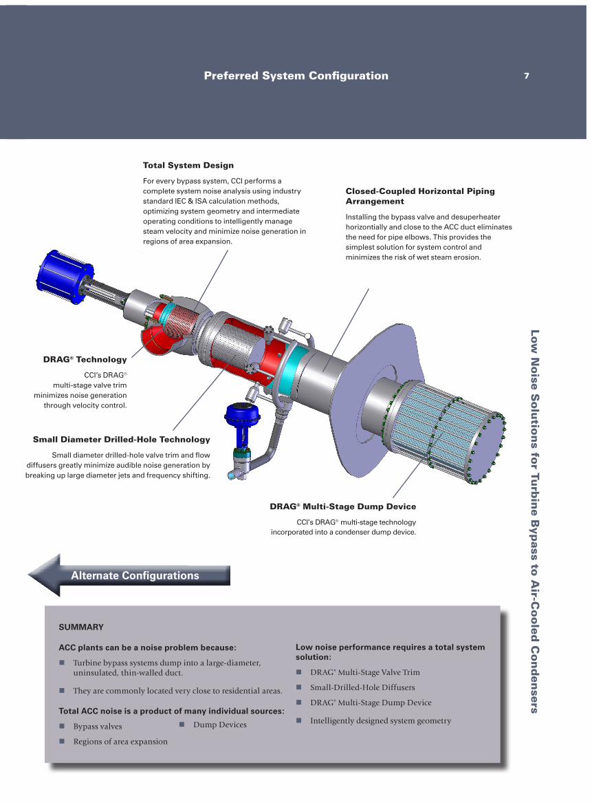
Small Diameter Drilled-Hole Technology
Small diameter drilled-hole valve trim and flow diffusers greatly minimize audible noise generation by breaking up large diameter jets and frequency shifting.
DRAG® Multi-Stage Dump Device
CCI’s DRAG® multi-stage technology incorporated into a condenser dump device.
Total System Design
For every bypass system, CCI performs a complete system noise analysis using industry standard IEC & ISA calculation methods, optimizing system geometry and intermediate operating conditions to intelligently manage steam velocity and minimize noise generation in regions of area expansion.
Closed-Coupled Horizontal Piping Arrangement
Installing the bypass valve and desuperheater horizontially and close to the ACC duct eliminates the need for pipe elbows. This provides the simplest solution for system control and minimizes the risk of wet steam erosion.
DRAG® Technology
CCI’s DRAG® multi-stage valve trim
minimizes noise generation through velocity control.
SUMMARY
ACC plants can be a noise problem because:
n Turbine bypass systems dump into a large-diameter, uninsulated, thin-walled duct.
n They are commonly located very close to residential areas.
Total ACC noise is a product of many individual sources:
n Bypass valves
n Regions of area expansion
Low noise performance requires a total system solution:
n DRAG® Multi-Stage Valve Trim
n Small-Drilled-Hole Diffusers
n DRAG® Multi-Stage Dump Device
n Intelligently designed system geometryn Dump Devices
Alternate Configurations
Low
Noise S
olu
tion
s for Tu
rbin
e Byp
ass to A
ir-Cooled
Con
den
sers
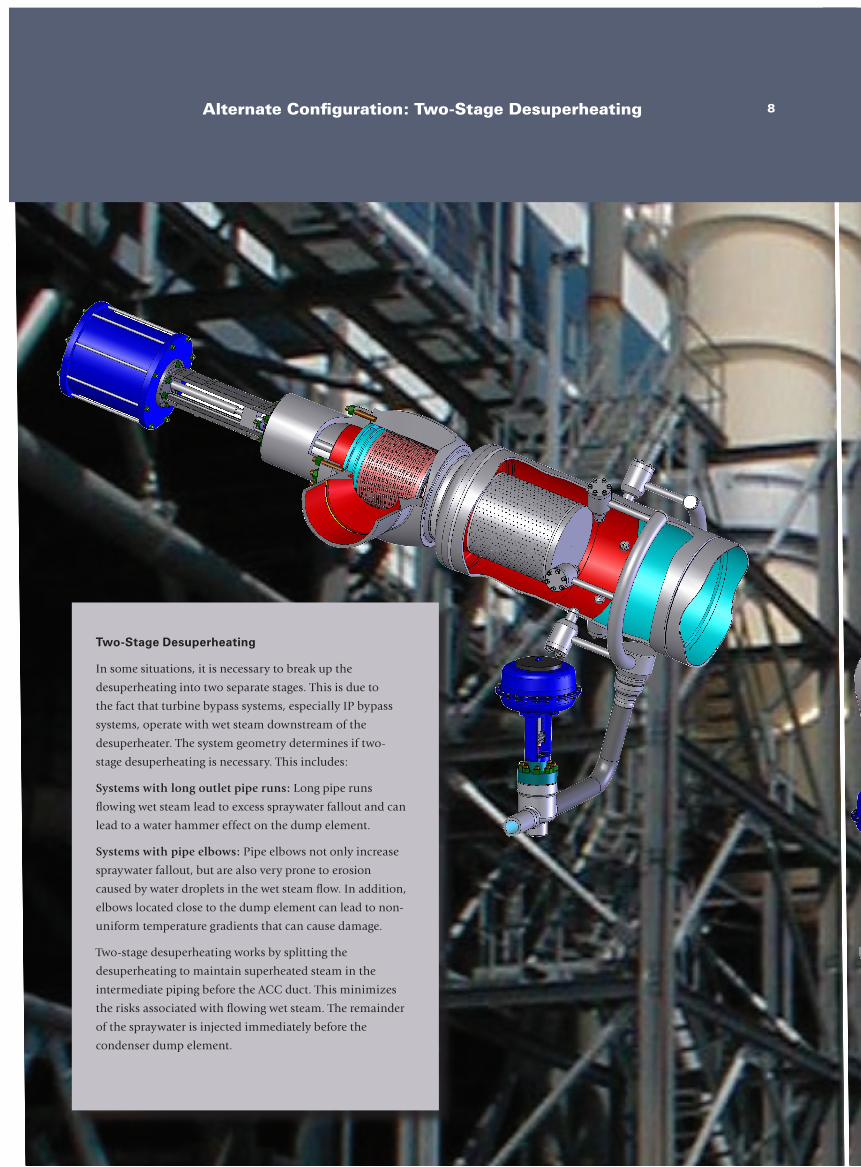
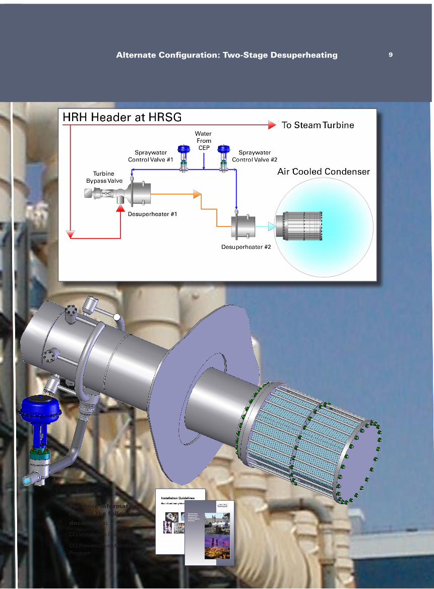
Two-Stage Desuperheating
In some situations, it is necessary to break up the
desuperheating into two separate stages. This is due to
the fact that turbine bypass systems, especially IP bypass
systems, operate with wet steam downstream of the
desuperheater. The system geometry determines if two-
stage desuperheating is necessary. This includes:
Systems with long outlet pipe runs: Long pipe runs
flowing wet steam lead to excess spraywater fallout and can
lead to a water hammer effect on the dump element.
Systems with pipe elbows: Pipe elbows not only increase
spraywater fallout, but are also very prone to erosion
caused by water droplets in the wet steam flow. In addition,
elbows located close to the dump element can lead to non-
uniform temperature gradients that can cause damage.
Two-stage desuperheating works by splitting the
desuperheating to maintain superheated steam in the
intermediate piping before the ACC duct. This minimizes
the risks associated with flowing wet steam. The remainder
of the spraywater is injected immediately before the
condenser dump element.
8Alternate Configuration: Two-Stage Desuperheating
Low
Noise S
olu
tion
s for Tu
rbin
e Byp
ass to A
ir-Cooled
Con
den
sers
For more information, refer to the following
documents:
CCI Installation Guidelines
CCI Preventative Maintenance Program
Preventative Maintenance Program for Turbine Bypass Systems
-
9Alternate Configuration: Two-Stage Desuperheating
Contact us at: [email protected]
For sales and service locations worldwide, visit us online at: www.ccivalve.com
Throughout the world, customers rely on CCI companies to solve their severe service control valve problems. CCI has provided custom solutions for these and other industry applications for more than 80 years.
DRAG is a registered trademark of CCI.©2008 CCI 893 04/08 5K