liquid cooled asynchronous motors adf motor line … · project planning manual...
TRANSCRIPT
Project Planning Manual
DOK-MOTOR*-ADF1x4*****-PR01-EN-P
SYSTEM200
Liquid Cooled Asynchronous Motors ADFMotor Line ADF1x4
About this Documentation Asynchronous Motors ADF
DOK-MOTOR*-ADF1x4*****-PR01-EN-P
Liquid Cooled Asynchronous Motors ADF
Motor Line ADF1x4
Project Planning Manual
DOK-MOTOR*-ADF1x4*****-PR01-EN-P
• 27393401_Book.doc
• Document Number 120-1500-B318-01/EN
This documentation …
• explains product features and applications, technical data as well asconditions and limits for operation.
• provides guidelines for product selection, applicvation, handling andoperation.
Description ReleaseDate
Notes
DOK-MOTOR*-ADF1x4*****-PR01-EN-P 10.2001 1st edition for motor seriesADF1x4
2001 Rexroth Indramat GmbH
Copying this document, giving it to others and the use or communicationof the contents thereof without express authority, are forbidden. Offendersare liable for the payment of damages. All rights are reserved in the eventof the grant of a patent or the registration of a utility model or design(DIN 34-1).
The specified data is for product description purposes only and may notbe deemed to be guaranteed unless expressly confirmed in the contract.All rights are reserved with respect to the content of this documentationand the availability of the product.
Rexroth Indramat GmbHBgm.-Dr.-Nebel-Str. 2 • D-97816 Lohr a. Main
Telephone +49 (0)93 52/40-0 • Tx 68 94 21 • Fax +49 (0)93 52/40-48 85
http://www.boschrexroth.de/
Dept. EDM1 (MS)
This document has been printed on chlorine-free bleached paper.
Title
Type of Documentation
Document Typecode
Internal File Reference
Purpose of Documentation
Record of Revisions
Copyright
Validity
Published by
Note
Asynchronous Motors ADF Table of Contents I
DOK-MOTOR*-ADF1x4*****-PR01-EN-P
Table of Contents
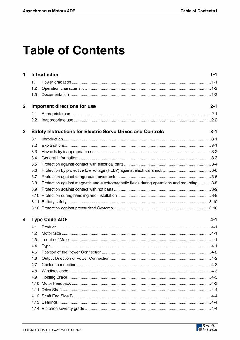
1 Introduction 1-1
1.1 Power gradation ............................................................................................................................. 1-1
1.2 Operation characteristic ................................................................................................................. 1-2
1.3 Documentation ............................................................................................................................... 1-3
2 Important directions for use 2-1
2.1 Appropriate use.............................................................................................................................. 2-1
2.2 Inappropriate use ........................................................................................................................... 2-2
3 Safety Instructions for Electric Servo Drives and Controls 3-1
3.1 Introduction..................................................................................................................................... 3-1
3.2 Explanations................................................................................................................................... 3-1
3.3 Hazards by inappropriate use ........................................................................................................ 3-2
3.4 General Information ....................................................................................................................... 3-3
3.5 Protection against contact with electrical parts .............................................................................. 3-4
3.6 Protection by protective low voltage (PELV) against electrical shock ........................................... 3-6
3.7 Protection against dangerous movements..................................................................................... 3-6
3.8 Protection against magnetic and electromagnetic fields during operations and mounting............ 3-8
3.9 Protection against contact with hot parts ....................................................................................... 3-9
3.10 Protection during handling and installation .................................................................................... 3-9
3.11 Battery safety ............................................................................................................................... 3-10
3.12 Protection against pressurized Systems...................................................................................... 3-10
4 Type Code ADF 4-1
4.1 Product ........................................................................................................................................... 4-1
4.2 Motor Size ...................................................................................................................................... 4-1
4.3 Length of Motor .............................................................................................................................. 4-1
4.4 Type ............................................................................................................................................... 4-1
4.5 Position of the Power Connection.................................................................................................. 4-2
4.6 Output Direction of Power Connection........................................................................................... 4-2
4.7 Coolant connection ........................................................................................................................ 4-3
4.8 Windings code................................................................................................................................ 4-3
4.9 Holding Brake................................................................................................................................. 4-3
4.10 Motor Feedback ............................................................................................................................. 4-3
4.11 Drive Shaft ..................................................................................................................................... 4-4
4.12 Shaft End Side B............................................................................................................................ 4-4
4.13 Bearings ......................................................................................................................................... 4-4
4.14 Vibration severity grade ................................................................................................................. 4-4
II Table of Contents Asynchronous Motors ADF
DOK-MOTOR*-ADF1x4*****-PR01-EN-P
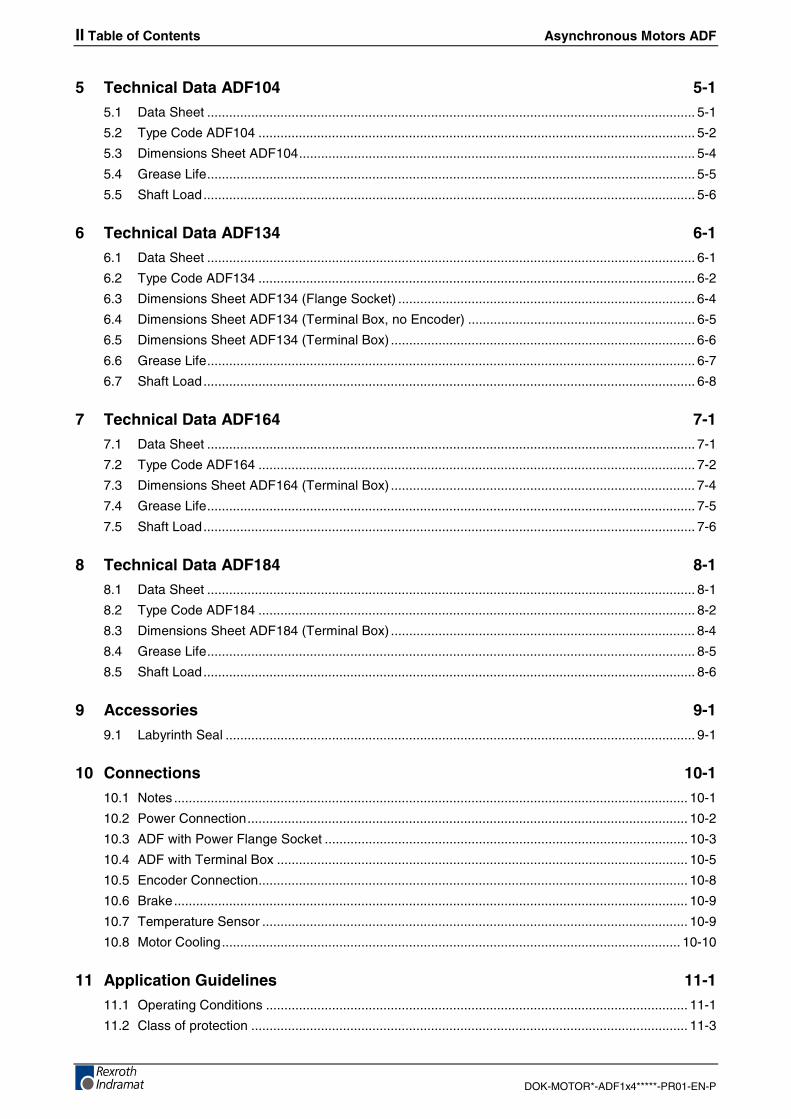
5 Technical Data ADF104 5-1
5.1 Data Sheet ..................................................................................................................................... 5-1
5.2 Type Code ADF104 ....................................................................................................................... 5-2
5.3 Dimensions Sheet ADF104............................................................................................................ 5-4
5.4 Grease Life..................................................................................................................................... 5-5
5.5 Shaft Load...................................................................................................................................... 5-6
6 Technical Data ADF134 6-1
6.1 Data Sheet ..................................................................................................................................... 6-1
6.2 Type Code ADF134 ....................................................................................................................... 6-2
6.3 Dimensions Sheet ADF134 (Flange Socket) ................................................................................. 6-4
6.4 Dimensions Sheet ADF134 (Terminal Box, no Encoder) .............................................................. 6-5
6.5 Dimensions Sheet ADF134 (Terminal Box) ................................................................................... 6-6
6.6 Grease Life..................................................................................................................................... 6-7
6.7 Shaft Load...................................................................................................................................... 6-8
7 Technical Data ADF164 7-1
7.1 Data Sheet ..................................................................................................................................... 7-1
7.2 Type Code ADF164 ....................................................................................................................... 7-2
7.3 Dimensions Sheet ADF164 (Terminal Box) ................................................................................... 7-4
7.4 Grease Life..................................................................................................................................... 7-5
7.5 Shaft Load...................................................................................................................................... 7-6
8 Technical Data ADF184 8-1
8.1 Data Sheet ..................................................................................................................................... 8-1
8.2 Type Code ADF184 ....................................................................................................................... 8-2
8.3 Dimensions Sheet ADF184 (Terminal Box) ................................................................................... 8-4
8.4 Grease Life..................................................................................................................................... 8-5
8.5 Shaft Load...................................................................................................................................... 8-6
9 Accessories 9-1
9.1 Labyrinth Seal ................................................................................................................................ 9-1
10 Connections 10-1
10.1 Notes ............................................................................................................................................ 10-1
10.2 Power Connection........................................................................................................................ 10-2
10.3 ADF with Power Flange Socket ................................................................................................... 10-3
10.4 ADF with Terminal Box ................................................................................................................ 10-5
10.5 Encoder Connection..................................................................................................................... 10-8
10.6 Brake............................................................................................................................................ 10-9
10.7 Temperature Sensor .................................................................................................................... 10-9
10.8 Motor Cooling............................................................................................................................. 10-10
11 Application Guidelines 11-1
11.1 Operating Conditions ................................................................................................................... 11-1
11.2 Class of protection ....................................................................................................................... 11-3
Asynchronous Motors ADF Table of Contents III
DOK-MOTOR*-ADF1x4*****-PR01-EN-P
11.3 Installation in the Machine............................................................................................................ 11-4
11.4 Brakes .......................................................................................................................................... 11-7
11.5 Motor Encoder.............................................................................................................................. 11-9
11.6 Drive Shaft ................................................................................................................................. 11-10
11.7 Bearing and Shaft Load ............................................................................................................. 11-12
11.8 Vibration Level ........................................................................................................................... 11-17
11.9 Temperature Sensor .................................................................................................................. 11-17
11.10Motor Cooling............................................................................................................................. 11-18
12 Handling and Transport 12-1
12.1 Condition on Delivery ................................................................................................................... 12-1
12.2 Identification ................................................................................................................................. 12-2
12.3 Transport and Storage ................................................................................................................. 12-2
13 Installation 13-1
13.1 Safety ........................................................................................................................................... 13-1
13.2 Mechanical Installation................................................................................................................. 13-1
13.3 Electrical Connection ................................................................................................................... 13-3
14 Operation of ADF Motors 14-1
14.1 Commissioning............................................................................................................................. 14-1
14.2 Shutdown ..................................................................................................................................... 14-2
14.3 Disassembly................................................................................................................................. 14-2
14.4 Maintenance................................................................................................................................. 14-3
14.5 Troubleshooting ........................................................................................................................... 14-4
15 Service & Support 15-1
15.1 Helpdesk ...................................................................................................................................... 15-1
15.2 Service-Hotline............................................................................................................................. 15-1
15.3 Internet ......................................................................................................................................... 15-1
15.4 Vor der Kontaktaufnahme... - Before contacting us..................................................................... 15-1
15.5 Kundenbetreuungsstellen - Sales & Service Facilities ................................................................ 15-2
16 Appendix 16-1
16.1 List of standards........................................................................................................................... 16-1
17 Glossary 17-1
18 Index 18-1
IV Table of Contents Asynchronous Motors ADF
DOK-MOTOR*-ADF1x4*****-PR01-EN-P
Asynchronous Motors ADF Introduction 1-1
DOK-MOTOR*-ADF1x4*****-PR01-EN-P
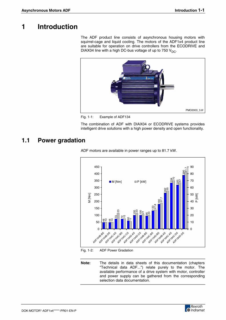
1 IntroductionThe ADF product line consists of asynchronous housing motors withsquirrel-cage and liquid cooling. The motors of the ADF1x4 product lineare suitable for operation on drive controllers from the ECODRIVE andDIAX04 line with a high DC-bus voltage of up to 750 VDC.
PMO2003_3.tif
Fig. 1-1: Example of ADF134
The combination of ADF with DIAX04 or ECODRIVE systems providesintelligent drive solutions with a high power density and open functionality.
1.1 Power gradation
ADF motors are available in power ranges up to 81.7 kW.
48 48
73 72
60
100
100
95
133
180
262
334
320
390
10 10
23
15
11
23 21 20
27,8
37,7
55
70
67
81,7
0
50
100
150
200
250
300
350
400
450
ADF104B
-BS
ADF104B
-DS
ADF104C
-AS
ADF104C
-BS
ADF104C
-CS
ADF104D
-AS
ADF104D
-CS
ADF134B
-BS
ADF134C
-BS
ADF134D
-BS
ADF164B
-AS
ADF164C
-AS
ADF184C
-DS
ADF184D
-DS
M[N
m]
0
10
20
30
40
50
60
70
80
90
P[k
W]
M [Nm] P [kW]
Fig. 1-2: ADF Power Gradation
Note: The details in data sheets of this documentation (chapters"Technical data ADF...") relate purely to the motor. Theavailable performance of a drive system with motor, controllerand power supply can be gathered from the correspondingselection data documentation.
1-2 Introduction Asynchronous Motors ADF
DOK-MOTOR*-ADF1x4*****-PR01-EN-P
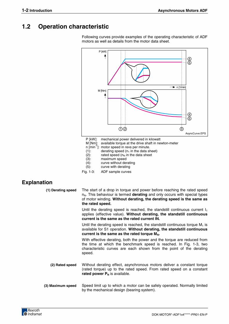
1.2 Operation characteristic
Following curves provide examples of the operating characteristic of ADFmotors as well as details from the motor data sheet.
3
45
45
P [kW]
M [Nm]
21
n [1/min]
AsyncCurve.EPS
P [kW]: mechanical power delivered in kilowattM [Nm]: available torque at the drive shaft in newton-metern [min-1]: motor speed in revs per minute.(1): derating speed (n1 in the data sheet)(2): rated speed (nN in the data sheet(3): maximum speed(4): curve without derating(5): curve with derating
Fig. 1-3: ADF sample curves
ExplanationThe start of a drop in torque and power before reaching the rated speednN. This behaviour is termed derating and only occurs with special typesof motor winding. Without derating, the derating speed is the same asthe rated speed.
Until the derating speed is reached, the standstill continuous current I1applies (effective value). Without derating, the standstill continuouscurrent is the same as the rated current IN.
Until the derating speed is reached, the standstill continuous torque M1 isavailable for S1 operation. Without derating, the standstill continuouscurrent is the same as the rated torque MN.
With effective derating, both the power and the torque are reduced fromthe time at which the benchmark speed is reached. In Fig. 1-3, twocharacteristic curves are each shown from the point of the deratingspeed.
Without derating effect, asynchronous motors deliver a constant torque(rated torque) up to the rated speed. From rated speed on a constantrated power PN is available.
Speed limit up to which a motor can be safely operated. Normally limitedby the mechanical design (bearing system).
(1) Derating speed
(2) Rated speed
(3) Maximum speed
Asynchronous Motors ADF Introduction 1-3
DOK-MOTOR*-ADF1x4*****-PR01-EN-P
1.3 Documentation
SummaryThis documentation describes exclusively the ADF1x4 motor line withsuitability for high DC-bus voltages.
Depending on the requirements, the following documentation also isrequired for planning drive systems using the ADF motor line.
Material No.: Title / Description Reference
00273934 DOK-MOTOR*-ADF1X4*****-PR01-EN-P"Project planning manual ADF, motor line 1x4..."
00271431 DOK-MOTOR*-ADF********-PR01-EN-P"Project planning manual ADF..."
ADF
00289233 DOK-DRIVE*-MAIN*WZM***-AU02-MS-E" AC main drives with 2AD- and ADF-motors"
00288730 (in preparation) DOK-DRIVE*-PRINT******-AU02-MS-E"Druckmaschinenantriebe..."
Selectiondata
00259814 DOK-GENERL-EMV********-PRJ1-EN-P" Electromagnetic Compatibility (EMC) in Drive and Control Systems“
EMV
00286117 DOK-CONNEC-CAB*INSTR02-MA01-EN-P"Cable assembly and tools for DIAX04 and ECODRIVE03“
00282688 DOK-CONNEC-CABLE*STAND-AU04-EN-P"Connecting Cables DIAX04, ECODRIVE03 and POWERDRIVE“
Cables andconnectors
1) The index (e.g. ..02-..) indicates the actual edition when this documentation was published.
Fig. 1-4: Documentation summary
Request the actual documentation for the products you are usingfrom your branch of REXROTH INDRAMAT (refer to address directory atthe end of this manual).
Third-Party SystemsDocumentation for external systems linked to REXROTH INDRAMATcomponents are not a part of the delivery and must be directly orderedfrom these manufacturers.

1-4 Introduction Asynchronous Motors ADF
DOK-MOTOR*-ADF1x4*****-PR01-EN-P
Asynchronous Motors ADF Important directions for use 2-1
DOK-MOTOR*-ADF1x4*****-PR01-EN-P
2 Important directions for use
2.1 Appropriate use
IntroductionRexroth Indramat products represent state-of-the-art developments andmanufacturing. They are tested prior to delivery to ensure operating safetyand reliability.
The products may only be used in the manner that is defined asappropriate. If they are used in an inappropriate manner, then situationscan develop that may lead to property damage or injury to personnel.
Note: Rexroth Indramat, as manufacturer, is not liable for anydamages resulting from inappropriate use. In such cases, theguarantee and the right to payment of damages resulting frominappropriate use are forfeited. The user alone carries allresponsibility of the risks.
Before using Rexroth Indramat products, make sure that all the pre-requisites for appropriate use of the products are satisfied:
• Personnel that in any way, shape or form uses our products must firstread and understand the relevant safety instructions and be familiarwith appropriate use.
• If the product takes the form of hardware, then they must remain intheir original state, in other words, no structural changes are permitted.It is not permitted to decompile software products or alter sourcecodes.
• Do not mount damaged or faulty products or use them in operation.
• Make sure that the products have been installed in the mannerdescribed in the relevant documentation.
2-2 Important directions for use Asynchronous Motors ADF
DOK-MOTOR*-ADF1x4*****-PR01-EN-P
Areas of use and applicationAsynchronous motors of the ADF line made by Rexroth Indramat aredesigned to be used as rotary main and servo drive motors. Typicalapplications are:
• machine tools,
• printing and paper processing machines,
• packaging and foodstuff machines and
• metal-forming machine tools.
Available for an application-specific use of the motors are unit types withdiffering drive power and different interfaces.
Control and monitoring of the motors may require additional sensors andactors.
Note: The motors may only be used with the accessories and partsspecified in this document. If a component has not beenspecifically named, then it may not be either mounted orconnected. The same applies to cables and lines.
Operation is only permitted in the specified configurations andcombinations of components using the software and firmwareas specified in the relevant function descriptions.
Every drive controller has to be programmed before starting it up, makingit possible for the motor to execute the specific functions of an application.
The motors may only be operated under the assembly, installation andambient conditions as described here (temperature, protection categories,humidity, EMC requirements, etc.) and in the position specified.
2.2 Inappropriate use
Using the motors outside of the above-referenced areas of application orunder operating conditions other than described in the document and thetechnical data specified is defined as “inappropriate use".
ADF motors may not be used if
• they are subject to operating conditions that do not meet the specifiedambient conditions. This includes, for example, operation underwater, in the case of extreme temperature fluctuations or extremelyhigh maximum temperatures or if
• Rexroth Indramat has not specifically released them for that intendedpurpose. Please note the specifications outlined in the general SafetyInstructions!
Asynchronous Motors ADF Safety Instructions for Electric Drives and Controls 3-1
DOK-MOTOR*-ADF1x4*****-PR01-EN-P
3 Safety Instructions for Electric Drives and Controls
3.1 Introduction
Read these instructions before the initial startup of the equipment in orderto eliminate the risk of bodily harm or material damage. Follow thesesafety instructions at all times.
Do not attempt to install or start up this equipment without first reading alldocumentation provided with the product. Read and understand thesesafety instructions and all user documentation of the equipment prior toworking with the equipment at any time. If you do not have the userdocumentation for your equipment, contact your local Rexroth Indramatrepresentative to send this documentation immediately to the person orpersons responsible for the safe operation of this equipment.
If the equipment is resold, rented or transferred or passed on to others,then these safety instructions must be delivered with the equipment.
WARNING
Improper use of this equipment, failure to followthe safety instructions in this document ortampering with the product, including disablingof safety devices, may result in materialdamage, bodily harm, electric shock or evendeath!
3.2 Explanations
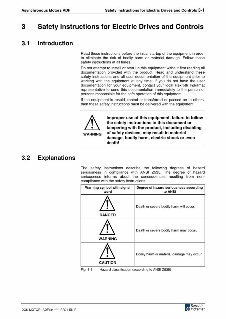
The safety instructions describe the following degrees of hazardseriousness in compliance with ANSI Z535. The degree of hazardseriousness informs about the consequences resulting from non-compliance with the safety instructions.
Warning symbol with signalword
Degree of hazard seriousness accordingto ANSI
DANGER
Death or severe bodily harm will occur.
WARNING
Death or severe bodily harm may occur.
CAUTION
Bodily harm or material damage may occur.
Fig. 3-1: Hazard classification (according to ANSI Z535)
3-2 Safety Instructions for Electric Drives and Controls Asynchronous Motors ADF
DOK-MOTOR*-ADF1x4*****-PR01-EN-P
3.3 Hazards by Improper Use
DANGER
High voltage and high discharge current!Danger to life or severe bodily harm by electricshock!
DANGER
Dangerous movements! Danger to life, severebodily harm or material damage byunintentional motor movements!
WARNING
High electrical voltage due to wrongconnections! Danger to life or bodily harm byelectric shock!
WARNING
Health hazard for persons with heartpacemakers, metal implants and hearing aids inproximity to electrical equipment!
CAUTION
Surface of machine housing could be extremelyhot! Danger of injury! Danger of burns!
CAUTION
Risk of injury due to improper handling! Bodilyharm caused by crushing, shearing, cutting andmechanical shock or incorrect handling ofpressurized systems!
CAUTION
Risk of injury due to incorrect handling ofbatteries!
Asynchronous Motors ADF Safety Instructions for Electric Drives and Controls 3-3
DOK-MOTOR*-ADF1x4*****-PR01-EN-P
3.4 General Information
Rexroth Indramat GmbH is not liable for damages resulting from failure toobserve the warnings provided in this documentation.
Read the operating, maintenance and safety instructions in your languagebefore starting up the machine. If you find that you cannot completelyunderstand the documentation for your product, please ask your supplierto clarify.
Proper and correct transport, storage, assembly and installation as wellas care in operation and maintenance are prerequisites for optimal andsafe operation of this equipment.
Only persons who are trained and qualified for the use and operation ofthe equipment may work on this equipment or within its proximity. Thepersons are qualified if they have sufficient knowledge of the assembly,installation and operation of the equipment as well as an understanding ofall warnings and precautionary measures noted in these instructions.Furthermore, they must be trained, instructed and qualified to switchelectrical circuits and equipment on and off in accordance with technicalsafety regulations, to ground them and to mark them according to therequirements of safe work practices. They must have adequate safetyequipment and be trained in first aid.
Only use spare parts and accessories approved by the manufacturer.
Follow all safety regulations and requirements for the specific applicationas practiced in the country of use.
The equipment is designed for installation in industrial machinery.
The ambient conditions given in the product documentation must beobserved.
Use only safety features and applications that are clearly and explicitlyapproved in the Project Planning Manual.For example, the following areas of use are not permitted: constructioncranes, elevators used for people or freight, devices and vehicles totransport people, medical applications, refinery plants, transport ofhazardous goods, nuclear applications, applications sensitive to highfrequency, mining, food processing, control of protection equipment (alsoin a machine).
The information given in this documentation with regard to the use of thedelivered components contains only examples of applications andsuggestions.The machine and installation manufacturer must
• make sure that the delivered components are suited for his individualapplication and check the information given in this documentation withregard to the use of the components,
• make sure that his application complies with the applicable safetyregulations and standards and carry out the required measures,modifications and complements.
Startup of the delivered components is only permitted once it is sure thatthe machine or installation in which they are installed complies with thenational regulations, safety specifications and standards of theapplication.
Operation is only permitted if the national EMC regulations for theapplication are met.The instructions for installation in accordance with EMC requirements canbe found in the documentation "EMC in Drive and Control Systems.”The machine or installation manufacturer is responsible for compliancewith the limiting values as prescribed in the national regulations.
Technical data, connections and operational conditions are specified inthe product documentation and must be followed at all times.
3-4 Safety Instructions for Electric Drives and Controls Asynchronous Motors ADF
DOK-MOTOR*-ADF1x4*****-PR01-EN-P
3.5 Protection Against Contact with Electrical Parts
Note: This section refers to equipment and drive components withvoltages above 50 Volts.
Touching live parts with voltages of 50 Volts and more with bare hands orconductive tools or touching ungrounded housings can be dangerous andcause electric shock. In order to operate electrical equipment, certainparts must unavoidably have dangerous voltages applied to them.
DANGER
High electrical voltage! Danger to life, severebodily harm by electric shock!⇒ Only those trained and qualified to work with or on
electrical equipment are permitted to operate, maintainor repair this equipment.
⇒ Follow general construction and safety regulations whenworking on high voltage installations.
⇒ Before switching on power the ground wire must bepermanently connected to all electrical units accordingto the connection diagram.
⇒ Do not operate electrical equipment at any time, evenfor brief measurements or tests, if the ground wire is notpermanently connected to the points of the componentsprovided for this purpose.
⇒ Before working with electrical parts with voltage higherthan 50 V, the equipment must be disconnected fromthe mains voltage or power supply. Make sure theequipment cannot be switched on again unintended.
⇒ The following should be observed with electrical driveand filter components:
⇒ Wait five (5) minutes after switching off power to allowcapacitors to discharge before beginning to work.Measure the voltage on the capacitors before beginningto work to make sure that the equipment is safe totouch.
⇒ Never touch the electrical connection points of acomponent while power is turned on.
⇒ Install the covers and guards provided with theequipment properly before switching the equipment on.Prevent contact with live parts at any time.
⇒ A residual-current-operated protective device (RCD)must not be used on electric drives! Indirect contactmust be prevented by other means, for example, by anovercurrent protective device.
⇒ Electrical components with exposed live parts anduncovered high voltage terminals must be installed in aprotective housing, for example, in a control cabinet.
Asynchronous Motors ADF Safety Instructions for Electric Drives and Controls 3-5
DOK-MOTOR*-ADF1x4*****-PR01-EN-P
To be observed with electrical drive and filter components:
DANGER
High electrical voltage on the housing!High leakage current! Danger to life, danger ofinjury by electric shock!⇒ Connect the electrical equipment, the housings of all
electrical units and motors permanently with the safetyconductor at the ground points before power isswitched on. Look at the connection diagram. This iseven necessary for brief tests.
⇒ Connect the safety conductor of the electricalequipment always permanently and firmly to thesupply mains. Leakage current exceeds 3.5 mA innormal operation.
⇒ Use a copper conductor with at least 10 mm² crosssection over its entire course for this safety conductorconnection!
⇒ Prior to startups, even for brief tests, always connectthe protective conductor or connect with ground wire.Otherwise, high voltages can occur on the housingthat lead to electric shock.
3.6 Protection Against Electric Shock by Protective LowVoltage (PELV)
All connections and terminals with voltages between 0 and 50 Volts onRexroth Indramat products are protective low voltages designed inaccordance with international standards on electrical safety.
WARNING
High electrical voltage due to wrongconnections! Danger to life, bodily harm byelectric shock!⇒ Only connect equipment, electrical components and
cables of the protective low voltage type (PELV =Protective Extra Low Voltage) to all terminals andclamps with voltages of 0 to 50 Volts.
⇒ Only electrical circuits may be connected which aresafely isolated against high voltage circuits. Safeisolation is achieved, for example, with an isolatingtransformer, an opto-electronic coupler or whenbattery-operated.
3-6 Safety Instructions for Electric Drives and Controls Asynchronous Motors ADF
DOK-MOTOR*-ADF1x4*****-PR01-EN-P
3.7 Protection Against Dangerous Movements
Dangerous movements can be caused by faulty control of the connectedmotors. Some common examples are:
• improper or wrong wiring of cable connections
• incorrect operation of the equipment components
• wrong input of parameters before operation
• malfunction of sensors, encoders and monitoring devices
• defective components
• software or firmware errors
Dangerous movements can occur immediately after equipment isswitched on or even after an unspecified time of trouble-free operation.
The monitoring in the drive components will normally be sufficient to avoidfaulty operation in the connected drives. Regarding personal safety,especially the danger of bodily injury and material damage, this alonecannot be relied upon to ensure complete safety. Until the integratedmonitoring functions become effective, it must be assumed in any casethat faulty drive movements will occur. The extent of faulty drivemovements depends upon the type of control and the state of operation.
Asynchronous Motors ADF Safety Instructions for Electric Drives and Controls 3-7
DOK-MOTOR*-ADF1x4*****-PR01-EN-P
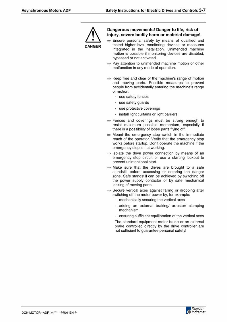
DANGER
Dangerous movements! Danger to life, risk ofinjury, severe bodily harm or material damage!⇒ Ensure personal safety by means of qualified and
tested higher-level monitoring devices or measuresintegrated in the installation. Unintended machinemotion is possible if monitoring devices are disabled,bypassed or not activated.
⇒ Pay attention to unintended machine motion or othermalfunction in any mode of operation.
⇒ Keep free and clear of the machine’s range of motionand moving parts. Possible measures to preventpeople from accidentally entering the machine’s rangeof motion:
- use safety fences
- use safety guards
- use protective coverings
- install light curtains or light barriers
⇒ Fences and coverings must be strong enough toresist maximum possible momentum, especially ifthere is a possibility of loose parts flying off.
⇒ Mount the emergency stop switch in the immediatereach of the operator. Verify that the emergency stopworks before startup. Don’t operate the machine if theemergency stop is not working.
⇒ Isolate the drive power connection by means of anemergency stop circuit or use a starting lockout toprevent unintentional start.
⇒ Make sure that the drives are brought to a safestandstill before accessing or entering the dangerzone. Safe standstill can be achieved by switching offthe power supply contactor or by safe mechanicallocking of moving parts.
⇒ Secure vertical axes against falling or dropping afterswitching off the motor power by, for example:
- mechanically securing the vertical axes
- adding an external braking/ arrester/ clampingmechanism
- ensuring sufficient equilibration of the vertical axes
The standard equipment motor brake or an externalbrake controlled directly by the drive controller arenot sufficient to guarantee personal safety!
3-8 Safety Instructions for Electric Drives and Controls Asynchronous Motors ADF
DOK-MOTOR*-ADF1x4*****-PR01-EN-P
⇒ Disconnect electrical power to the equipment using amaster switch and secure the switch againstreconnection for:
- maintenance and repair work
- cleaning of equipment
- long periods of discontinued equipment use
⇒ Prevent the operation of high-frequency, remotecontrol and radio equipment near electronics circuitsand supply leads. If the use of such equipment cannotbe avoided, verify the system and the installation forpossible malfunctions in all possible positions ofnormal use before initial startup. If necessary, performa special electromagnetic compatibility (EMC) test onthe installation.
3.8 Protection Against Magnetic and Electromagnetic FieldsDuring Operation and Mounting
Magnetic and electromagnetic fields generated near current-carryingconductors and permanent magnets in motors represent a serious healthhazard to persons with heart pacemakers, metal implants and hearingaids.
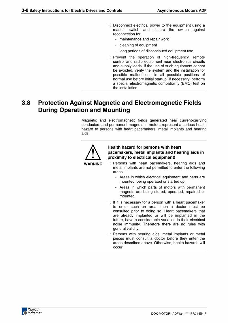
WARNING
Health hazard for persons with heartpacemakers, metal implants and hearing aids inproximity to electrical equipment!⇒ Persons with heart pacemakers, hearing aids and
metal implants are not permitted to enter the followingareas:
- Areas in which electrical equipment and parts aremounted, being operated or started up.
- Areas in which parts of motors with permanentmagnets are being stored, operated, repaired ormounted.
⇒ If it is necessary for a person with a heart pacemakerto enter such an area, then a doctor must beconsulted prior to doing so. Heart pacemakers thatare already implanted or will be implanted in thefuture, have a considerable variation in their electricalnoise immunity. Therefore there are no rules withgeneral validity.
⇒ Persons with hearing aids, metal implants or metalpieces must consult a doctor before they enter theareas described above. Otherwise, health hazards willoccur.
Asynchronous Motors ADF Safety Instructions for Electric Drives and Controls 3-9
DOK-MOTOR*-ADF1x4*****-PR01-EN-P
3.9 Protection Against Contact with Hot Parts
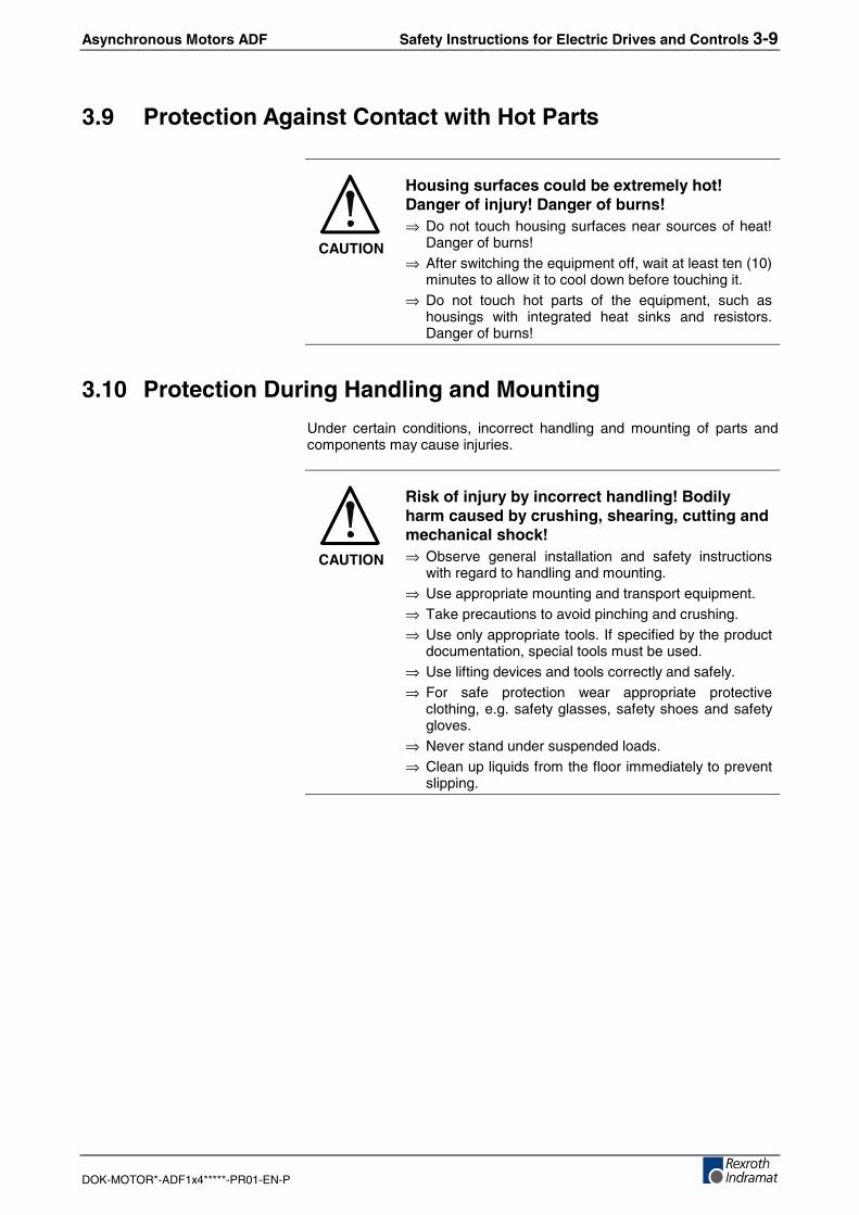
CAUTION
Housing surfaces could be extremely hot!Danger of injury! Danger of burns!⇒ Do not touch housing surfaces near sources of heat!
Danger of burns!⇒ After switching the equipment off, wait at least ten (10)
minutes to allow it to cool down before touching it.⇒ Do not touch hot parts of the equipment, such as
housings with integrated heat sinks and resistors.Danger of burns!
3.10 Protection During Handling and Mounting
Under certain conditions, incorrect handling and mounting of parts andcomponents may cause injuries.
CAUTION
Risk of injury by incorrect handling! Bodilyharm caused by crushing, shearing, cutting andmechanical shock!⇒ Observe general installation and safety instructions
with regard to handling and mounting.⇒ Use appropriate mounting and transport equipment.⇒ Take precautions to avoid pinching and crushing.⇒ Use only appropriate tools. If specified by the product
documentation, special tools must be used.⇒ Use lifting devices and tools correctly and safely.⇒ For safe protection wear appropriate protective
clothing, e.g. safety glasses, safety shoes and safetygloves.
⇒ Never stand under suspended loads.⇒ Clean up liquids from the floor immediately to prevent
slipping.
3-10 Safety Instructions for Electric Drives and Controls Asynchronous Motors ADF
DOK-MOTOR*-ADF1x4*****-PR01-EN-P
3.11 Battery Safety
Batteries contain reactive chemicals in a solid housing. Inappropriatehandling may result in injuries or material damage.
CAUTION
Risk of injury by incorrect handling!⇒ Do not attempt to reactivate discharged batteries by
heating or other methods (danger of explosion andcauterization).
⇒ Never charge non-chargeable batteries (danger ofleakage and explosion).
⇒ Never throw batteries into a fire.⇒ Do not dismantle batteries.⇒ Do not damage electrical components installed in the
equipment.
Note: Be aware of environmental protection and disposal! Thebatteries contained in the product should be considered ashazardous material for land, air and sea transport in the senseof the legal requirements (danger of explosion). Disposebatteries separately from other waste. Observe the legalrequirements in the country of installation.
3.12 Protection Against Pressurized Systems
Certain motors and drive controllers, corresponding to the information inthe respective Project Planning Manual, must be provided withpressurized media, such as compressed air, hydraulic oil, cooling fluidand cooling lubricant supplied by external systems. Incorrect handling ofthe supply and connections of pressurized systems can lead to injuries oraccidents. In these cases, improper handling of external supply systems,supply lines or connections can cause injuries or material damage.
CAUTION
Danger of injury by incorrect handling ofpressurized systems !⇒ Do not attempt to disassemble, to open or to cut a
pressurized system (danger of explosion).⇒ Observe the operation instructions of the respective
manufacturer.⇒ Before disassembling pressurized systems, release
pressure and drain off the fluid or gas.⇒ Use suitable protective clothing (for example safety
glasses, safety shoes and safety gloves)⇒ Remove any fluid that has leaked out onto the floor
immediately.
Note: Environmental protection and disposal! The media used in theoperation of the pressurized system equipment may not beenvironmentally compatible. Media that are damaging theenvironment must be disposed separately from normal waste.Observe the legal requirements in the country of installation.
Asynchronous Motors ADF Type Code ADF 4-1
DOK-MOTOR*-ADF1x4*****-PR01-EN-P
4 Type Code ADFThe type code describes the various motor options that can be delivered.It is the basis for ordering and pricing of products, spare parts andproduct services from REXROTH INDRAMAT. The general figures ("Typecode column") of all ADF type codes are described in the following.
Notes:
• The individual type code for a particular motor size is a partof the respective chapter in this documentation.
• Explanations on the use of individual options is contained inthe chapter called "Application Guidelines".
4.1 Product
Type code column 1 2 3ADF is the name of the product line of liquid-cooled asynchronousmotors.
4.2 Motor Size
Type code column 4 5 6The size of the motor is derived from the height of the shaft (distance ofthe middle of the shaft from base contact area). The size results from theassignment to the most obvious standard shaft height.
Available sizes: ADF104/134/164/184.
4.3 Length of Motor
Type code column 7Within a product group, increasing length of motor is graded by ID lettersin alphabetic order. Normally, an increase in motor length results in ahigher continuous torque.
Lengths are, e.g.. B, C and D.
4.4 Type
Type code column 9 10 11ADF motors of the type B05 (flange mounting) or type B35 (footmounting) can be delivered. The permissible mounting arrangements areexplained in the chapter "Application Guidelines".
4-2 Type Code ADF Asynchronous Motors ADF
DOK-MOTOR*-ADF1x4*****-PR01-EN-P
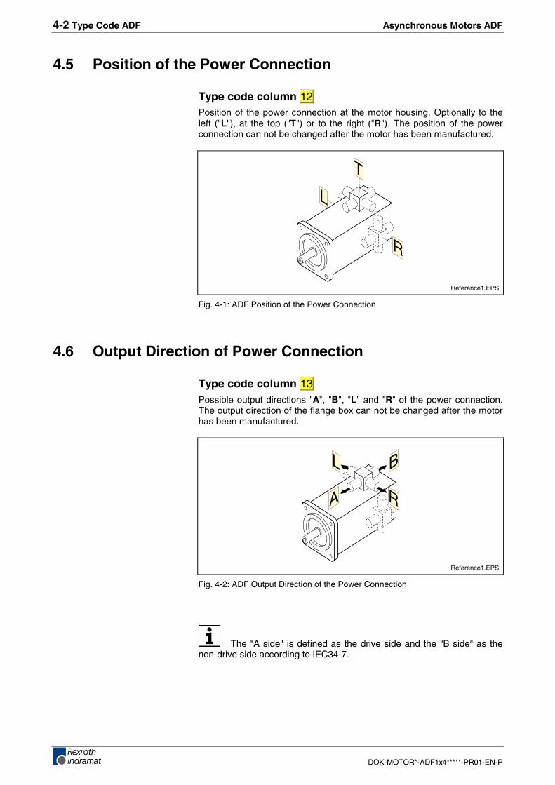
4.5 Position of the Power Connection
Type code column 12Position of the power connection at the motor housing. Optionally to theleft ("L"), at the top ("T") or to the right ("R"). The position of the powerconnection can not be changed after the motor has been manufactured.
R
L
T
Reference1.EPS
Fig. 4-1: ADF Position of the Power Connection
4.6 Output Direction of Power Connection
Type code column 13Possible output directions "A", "B", "L" and "R" of the power connection.The output direction of the flange box can not be changed after the motorhas been manufactured.
A
B
R
L
Reference1.EPS
Fig. 4-2: ADF Output Direction of the Power Connection
The "A side" is defined as the drive side and the "B side" as thenon-drive side according to IEC34-7.
Asynchronous Motors ADF Type Code ADF 4-3
DOK-MOTOR*-ADF1x4*****-PR01-EN-P
4.7 Coolant connection
Type code column 14ADF motors must always be operated with a liquid cooling system. Theconnections are on the B side (non-drive side)of the motor.
4.8 Windings code
Type code column 16 17Code for the type of winding. Winding code "•S" means a star connection.However, the drive combination is selected based on the respectiveselection data and operating characteristics.
4.9 Holding Brake
Type code column 18Some ADF motors can be delivered with an integrated holding brake.Depending on the application, you select the holding brake either with anelectrical lock or an electrical release.
Additional information is contained in the chapters "Technical DataADF1•4" and "Application Guidelines".
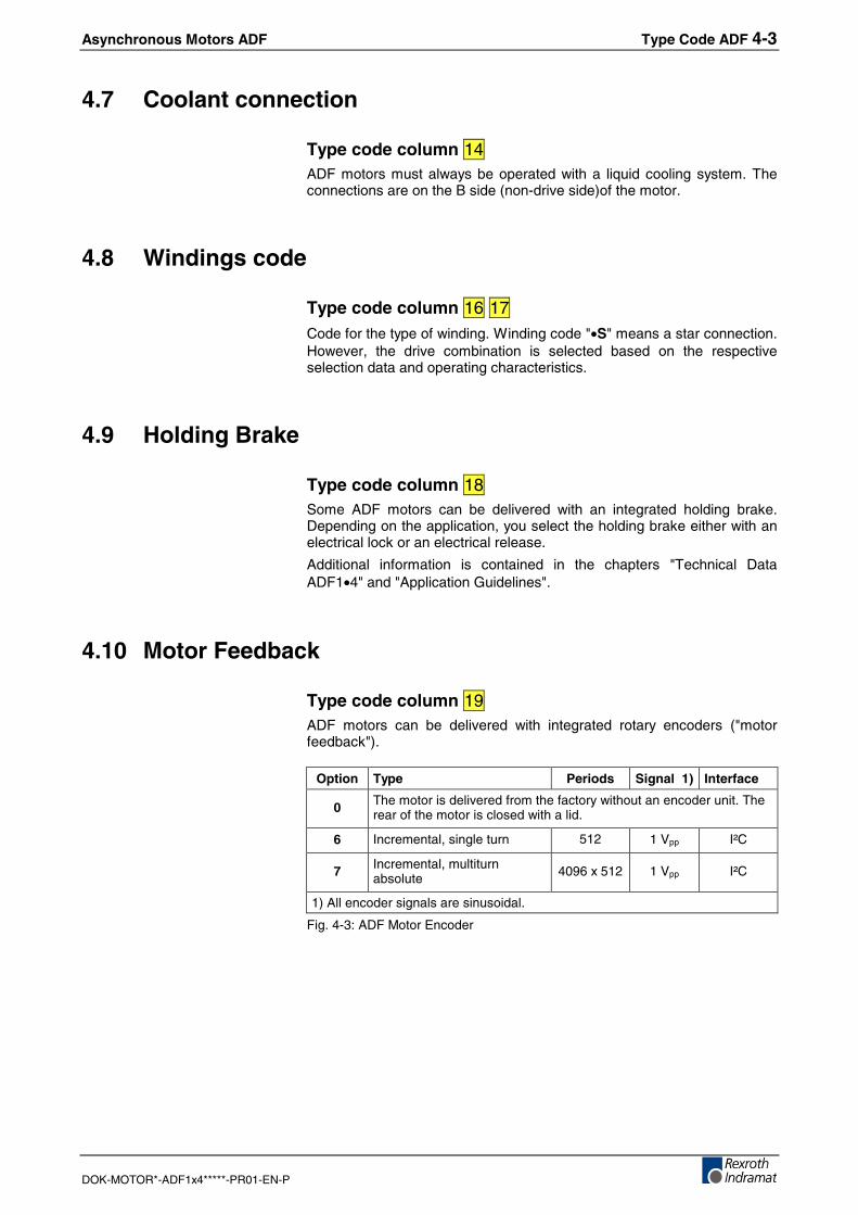
4.10 Motor Feedback
Type code column 19ADF motors can be delivered with integrated rotary encoders ("motorfeedback").
Option Type Periods Signal 1) Interface
0 The motor is delivered from the factory without an encoder unit. Therear of the motor is closed with a lid.
6 Incremental, single turn 512 1 Vpp I²C
7 Incremental, multiturnabsolute 4096 x 512 1 Vpp I²C
1) All encoder signals are sinusoidal.
Fig. 4-3: ADF Motor Encoder
4-4 Type Code ADF Asynchronous Motors ADF
DOK-MOTOR*-ADF1x4*****-PR01-EN-P
4.11 Drive Shaft
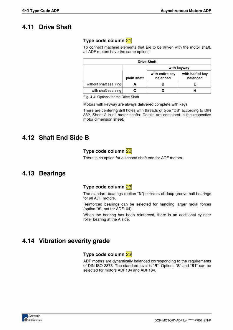
Type code column 21To connect machine elements that are to be driven with the motor shaft,all ADF motors have the same options:
Drive Shaft
with keyway
plain shaftwith entire key
balancedwith half of key
balanced
without shaft seal ring A B E
with shaft seal ring C D H
Fig. 4-4: Options for the Drive Shaft
Motors with keyway are always delivered complete with keys.
There are centering drill holes with threads of type "DS" according to DIN332, Sheet 2 in all motor shafts. Details are contained in the respectivemotor dimension sheet.
4.12 Shaft End Side B
Type code column 22There is no option for a second shaft end for ADF motors.
4.13 Bearings
Type code column 23The standard bearings (option "N") consists of deep-groove ball bearingsfor all ADF motors.
Reinforced bearings can be selected for handling larger radial forces(option "V", not for ADF104).
When the bearing has been reinforced, there is an additional cylinderroller bearing at the A side.
4.14 Vibration severity grade
Type code column 23ADF motors are dynamically balanced corresponding to the requirementsof DIN ISO 2373. The standard level is "R". Options "S" and "S1" can beselected for motors ADF134 and ADF164.
Asynchronous Motors ADF Technical Data ADF104 5-1
DOK-MOTOR*-ADF1x4*****-PR01-EN-P
5 Technical Data ADF104
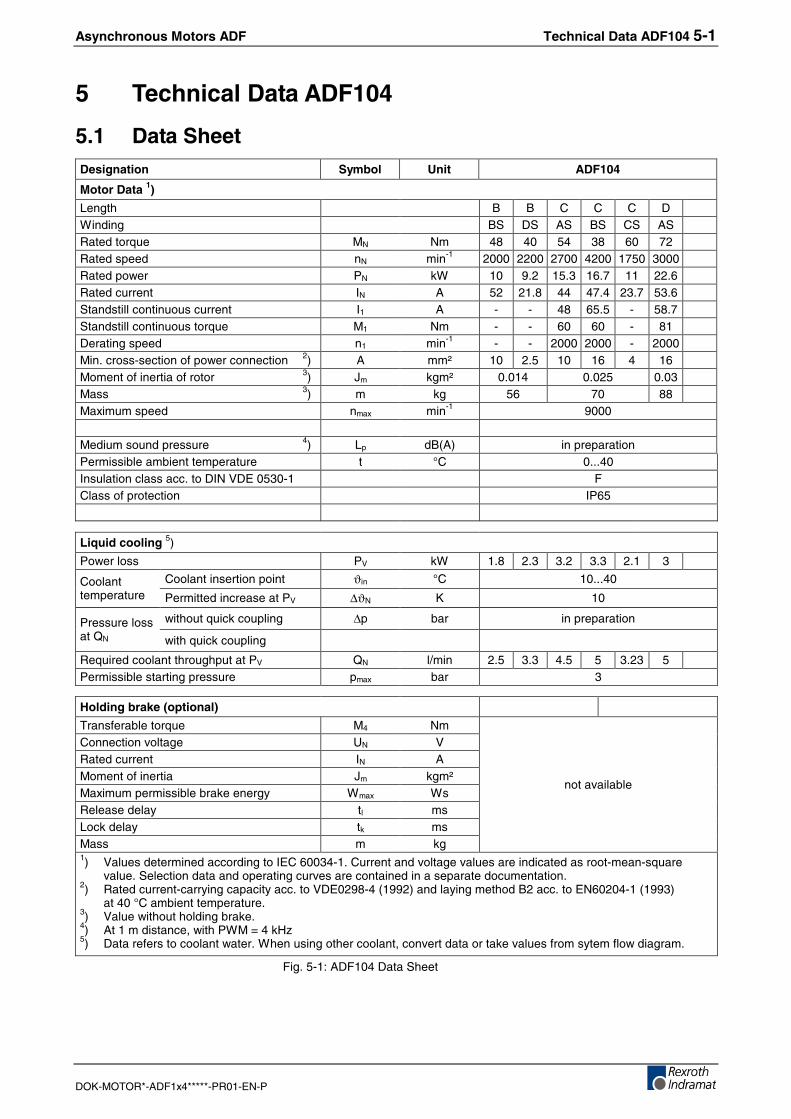
5.1 Data SheetDesignation Symbol Unit ADF104
Motor Data 1)
Length B B C C C DWinding BS DS AS BS CS ASRated torque MN Nm 48 40 54 38 60 72Rated speed nN min-1 2000 2200 2700 4200 1750 3000Rated power PN kW 10 9.2 15.3 16.7 11 22.6Rated current IN A 52 21.8 44 47.4 23.7 53.6Standstill continuous current I1 A - - 48 65.5 - 58.7Standstill continuous torque M1 Nm - - 60 60 - 81Derating speed n1 min-1 - - 2000 2000 - 2000Min. cross-section of power connection 2) A mm² 10 2.5 10 16 4 16Moment of inertia of rotor 3) Jm kgm² 0.014 0.025 0.03Mass 3) m kg 56 70 88Maximum speed nmax min-1 9000
Medium sound pressure 4) Lp dB(A) in preparationPermissible ambient temperature t °C 0...40Insulation class acc. to DIN VDE 0530-1 FClass of protection IP65
Liquid cooling 5)
Power loss PV kW 1.8 2.3 3.2 3.3 2.1 3
Coolant insertion point ϑin °C 10...40Coolanttemperature Permitted increase at PV ∆ϑN K 10
without quick coupling ∆p bar in preparationPressure lossat QN with quick coupling
Required coolant throughput at PV QN l/min 2.5 3.3 4.5 5 3.23 5Permissible starting pressure pmax bar 3
Holding brake (optional)
Transferable torque M4 NmConnection voltage UN VRated current IN AMoment of inertia Jm kgm²Maximum permissible brake energy Wmax WsRelease delay tl msLock delay tk msMass m kg
not available
1) Values determined according to IEC 60034-1. Current and voltage values are indicated as root-mean-squarevalue. Selection data and operating curves are contained in a separate documentation.
2) Rated current-carrying capacity acc. to VDE0298-4 (1992) and laying method B2 acc. to EN60204-1 (1993)at 40 °C ambient temperature.
3) Value without holding brake.4) At 1 m distance, with PWM = 4 kHz5) Data refers to coolant water. When using other coolant, convert data or take values from sytem flow diagram.
Fig. 5-1: ADF104 Data Sheet
5-2 Technical Data ADF104 Asynchronous Motors ADF
DOK-MOTOR*-ADF1x4*****-PR01-EN-P
5.2 Type Code ADF104
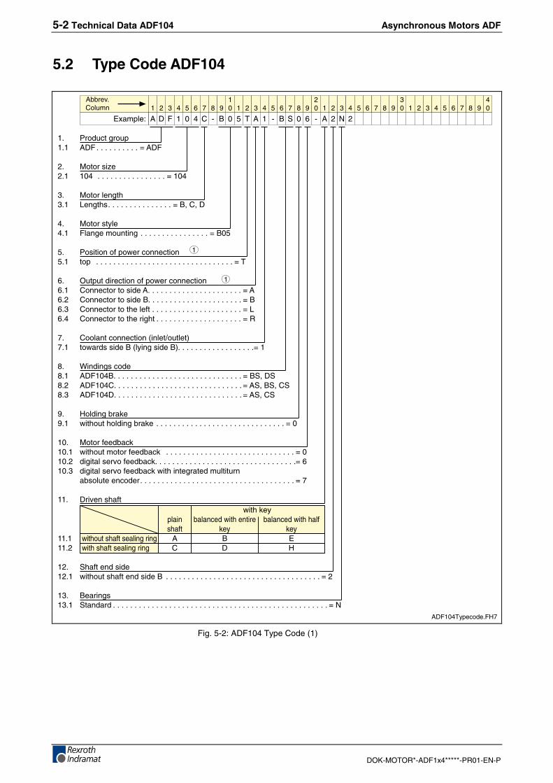
1. Product group1.1 ADF . . . . . . . . . . = ADF
2. Motor size2.1 104 . . . . . . . . . . . . . . . . = 104
3. Motor length3.1 Lengths. . . . . . . . . . . . . . . = B, C, D
4. Motor style4.1 Flange mounting . . . . . . . . . . . . . . . . = B05
5. Position of power connection5.1 top . . . . . . . . . . . . . . . . . . . . . . . . . . . . . . . . = T
6. Output direction of power connection6.1 Connector to side A. . . . . . . . . . . . . . . . . . . . . . = A6.2 Connector to side B. . . . . . . . . . . . . . . . . . . . . . = B6.3 Connector to the left . . . . . . . . . . . . . . . . . . . . . = L6.4 Connector to the right . . . . . . . . . . . . . . . . . . . . = R
7. Coolant connection (inlet/outlet)7.1 towards side B (lying side B). . . . . . . . . . . . . . . . . .= 1
8. Windings code8.1 ADF104B. . . . . . . . . . . . . . . . . . . . . . . . . . . . . . = BS, DS8.2 ADF104C. . . . . . . . . . . . . . . . . . . . . . . . . . . . . . = AS, BS, CS8.3 ADF104D. . . . . . . . . . . . . . . . . . . . . . . . . . . . . . = AS, CS
9. Holding brake9.1 without holding brake . . . . . . . . . . . . . . . . . . . . . . . . . . . . . . = 0
10. Motor feedback10.1 without motor feedback . . . . . . . . . . . . . . . . . . . . . . . . . . . . . . = 010.2 digital servo feedback. . . . . . . . . . . . . . . . . . . . . . . . . . . . . . . . .= 610.3 digital servo feedback with integrated multiturn
absolute encoder. . . . . . . . . . . . . . . . . . . . . . . . . . . . . . . . . . . . = 7
11. Driven shaftwith key
plain balanced with entire balanced with half shaft key key
11.1 without shaft sealing ring A B E11.2 with shaft sealing ring C D H
12. Shaft end side12.1 without shaft end side B . . . . . . . . . . . . . . . . . . . . . . . . . . . . . . . . . . . . = 2
13. Bearings13.1 Standard . . . . . . . . . . . . . . . . . . . . . . . . . . . . . . . . . . . . . . . . . . . . . . . . . . = N
1 2 3 4 6 7 8 9105 1 2 3 4 6 7 8 9
205 1 2 3 4 6 7 8 9
305 1 2 3 4 6 7 8 9
405
Example:
Abbrev.Column
A D F 1 0 4 C - B 0 5 T A 1 - B S 0 6 - A 2 N 2
1
1
ADF104Typecode.FH7
Fig. 5-2: ADF104 Type Code (1)
Asynchronous Motors ADF Technical Data ADF104 5-3
DOK-MOTOR*-ADF1x4*****-PR01-EN-P
��� �������� ���������������� � ������������������������������������������������������������������������������������������������������������������� ������� � ������������������������������������������������������������������������������������������������������������������� ���
�� ������������������������������
� � � � � � � �� ! � � � � � � � �
� ! � � � � � � � �
� ! � � � � � � � �
� !
"#��$%�
������������
& ' ( � � ) * + ! , & � * + � � * & � �
�
ADF104Typecode1.FH7
Fig. 5-3: ADF104 Type Code (2)
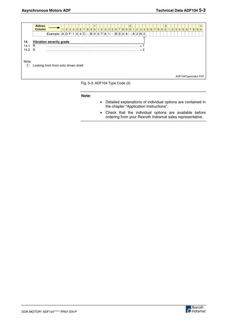
Note:
• Detailed explanations of individual options are contained inthe chapter "Application Instructions".
• Check that the individual options are available beforeordering from your Rexroth Indramat sales representative.
5-4 Technical Data ADF104 Asynchronous Motors ADF
DOK-MOTOR*-ADF1x4*****-PR01-EN-P
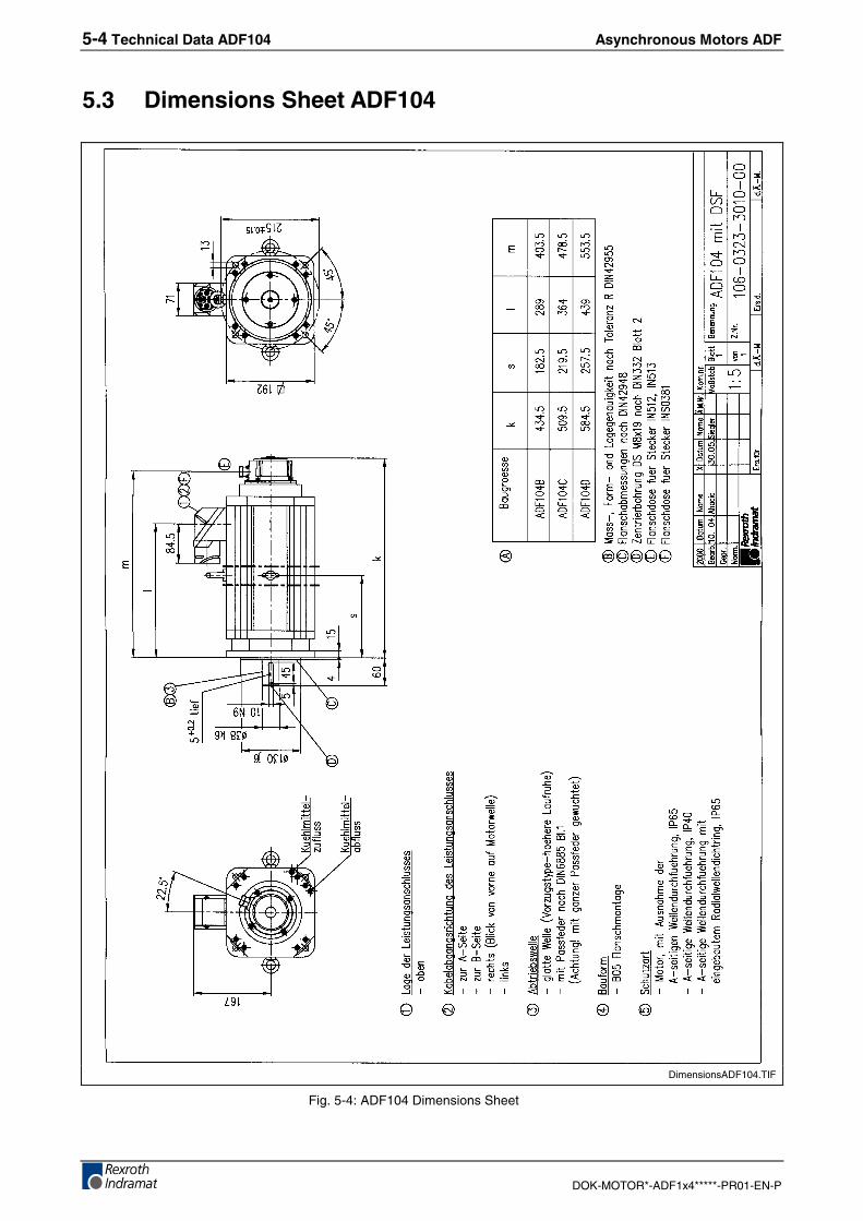
5.3 Dimensions Sheet ADF104
DimensionsADF104.TIF
Fig. 5-4: ADF104 Dimensions Sheet
Asynchronous Motors ADF Technical Data ADF104 5-5
DOK-MOTOR*-ADF1x4*****-PR01-EN-P
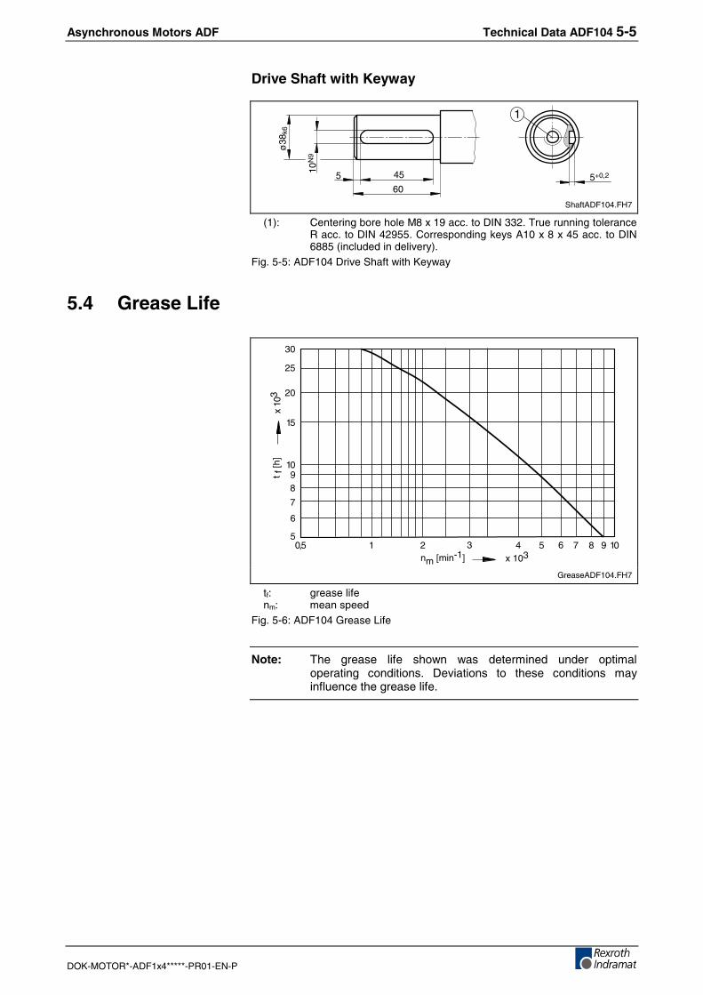
Drive Shaft with Keyway
10N
9
45
60
ø38
k6
5 5+0,2
1
ShaftADF104.FH7
(1): Centering bore hole M8 x 19 acc. to DIN 332. True running toleranceR acc. to DIN 42955. Corresponding keys A10 x 8 x 45 acc. to DIN6885 (included in delivery).
Fig. 5-5: ADF104 Drive Shaft with Keyway
5.4 Grease Life
5
10
20
6
7
89
15
25
30
x 10
3
0,5 1 2 3 4 65 7 8 9 10x 103nm [min-1]
t f [h
]
GreaseADF104.FH7
tf: grease lifenm: mean speed
Fig. 5-6: ADF104 Grease Life
Note: The grease life shown was determined under optimaloperating conditions. Deviations to these conditions mayinfluence the grease life.
5-6 Technical Data ADF104 Asynchronous Motors ADF
DOK-MOTOR*-ADF1x4*****-PR01-EN-P
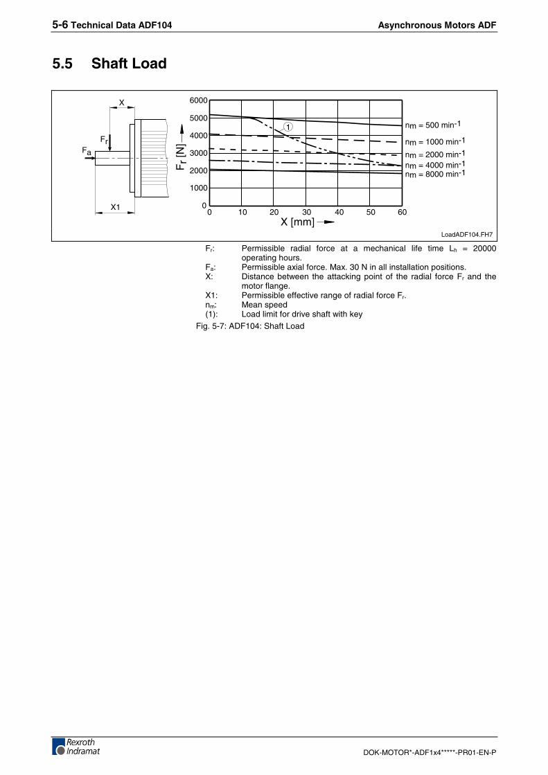
5.5 Shaft Load
X [mm]
0
1000
2000
3000
4000
5000
6000
0 10 20 30 40 6050
Fr
[N]
nm = 4000 min-1nm = 8000 min-1
nm = 500 min-1
nm = 1000 min-1
nm = 2000 min-1
1
X1
X
FrFa
LoadADF104.FH7
Fr: Permissible radial force at a mechanical life time Lh = 20000operating hours.
Fa: Permissible axial force. Max. 30 N in all installation positions.X: Distance between the attacking point of the radial force Fr and the
motor flange.X1: Permissible effective range of radial force Fr.nm: Mean speed(1): Load limit for drive shaft with key
Fig. 5-7: ADF104: Shaft Load
Asynchronous Motors ADF Technical Data ADF134 6-1
DOK-MOTOR*-ADF1x4*****-PR01-EN-P
6 Technical Data ADF134
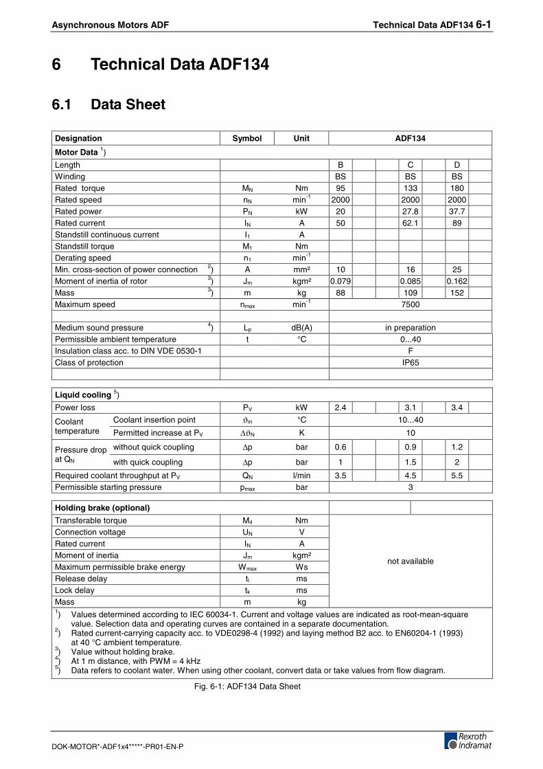
6.1 Data Sheet
Designation Symbol Unit ADF134
Motor Data 1)
Length B C DWinding BS BS BSRated torque MN Nm 95 133 180Rated speed nN min-1 2000 2000 2000Rated power PN kW 20 27.8 37.7Rated current IN A 50 62.1 89Standstill continuous current I1 AStandstill torque M1 NmDerating speed n1 min-1
Min. cross-section of power connection 2) A mm² 10 16 25Moment of inertia of rotor 3) Jm kgm² 0.079 0.085 0.162Mass 3) m kg 88 109 152Maximum speed nmax min-1 7500
Medium sound pressure 4) Lp dB(A) in preparationPermissible ambient temperature t °C 0...40Insulation class acc. to DIN VDE 0530-1 FClass of protection IP65
Liquid cooling 5)
Power loss PV kW 2.4 3.1 3.4
Coolant insertion point ϑin °C 10...40Coolanttemperature Permitted increase at PV ∆ϑN K 10
without quick coupling ∆p bar 0.6 0.9 1.2Pressure dropat QN with quick coupling ∆p bar 1 1.5 2
Required coolant throughput at PV QN l/min 3.5 4.5 5.5Permissible starting pressure pmax bar 3
Holding brake (optional)
Transferable torque M4 NmConnection voltage UN VRated current IN AMoment of inertia Jm kgm²Maximum permissible brake energy Wmax WsRelease delay tl msLock delay tk msMass m kg
not available
1) Values determined according to IEC 60034-1. Current and voltage values are indicated as root-mean-squarevalue. Selection data and operating curves are contained in a separate documentation.
2) Rated current-carrying capacity acc. to VDE0298-4 (1992) and laying method B2 acc. to EN60204-1 (1993)at 40 °C ambient temperature.
3) Value without holding brake.4) At 1 m distance, with PWM = 4 kHz5) Data refers to coolant water. When using other coolant, convert data or take values from flow diagram.
Fig. 6-1: ADF134 Data Sheet
6-2 Technical Data ADF134 Asynchronous Motors ADF
DOK-MOTOR*-ADF1x4*****-PR01-EN-P
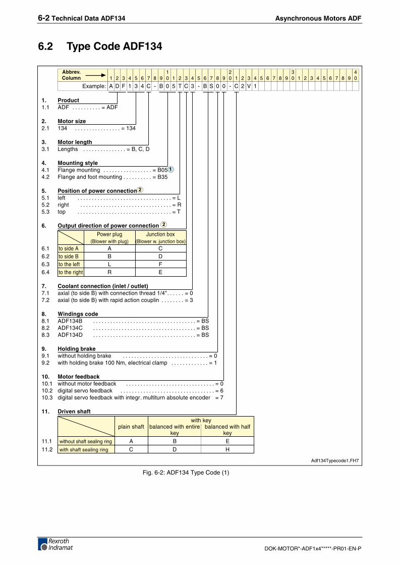
6.2 Type Code ADF134
�� �������� &'( ������������������� ��&'(
�� ��� ������ ��� ������������������������������� �����
�� ����������� ������� ����������������������������� ��+-�)-�'
�� ������� ������ (%������.����� ��������������������������������� ��+ !��� (%�������������.����� ������������������� ��+�!
�� � ���� �!"����������!�� %��� ����������������������������������������������������������������� ���!�� ����� ��������������������������������������������������������������� ���!�� �$ ����������������������������������������������������������������� ��,
#� $�!���������� �!"����������
/0���$%.� 1.�2����3#4+%0���0����$%.�5 4+%0���0��6.�2����3#5
��� �������& & )��� �������+ + '��� ������%��� � (��� ����������� � "
%� �������������&�����'����(��� �#��%�4�������+5�0����2���2������������7�8����������� �� ��� �#��%�4�������+5�0������$����2����2.$%�� ��������������� ���
)� *������ ������� &'(���+ ����������������������������������������������������������������������� ��+���� &'(���) ����������������������������������������������������������������������� ��+���� &'(���' ����������������������������������������������������������������������� ��+�
+� ,���������-���� 0���.���%�����3���� ����������������������������������������������������������� �� ��� 0�����%�����3������ ��-��%�2���2�%�2%��$ ������������������������� ���
�.� ��� ������-� �� 0���.����������3�2� ������������������������������������������������������������� �� � �� ������%����������3�2� ����������������������������������������������������������������� ���� ��� ������%����������3�2��0�������������.%���.����3�%.�����2��� ���
��� /������ ��
� 0������9$%��������� 3�%��2���0���������� 3�%��2���0������%�
��9 ��9���� 0���.�����������%�������� & + "���� 0�������������%�������� ) ' :
� � � � � � � �� ! � � � � � � � �
� ! � � � � � � � �
� ! � � � � � � � �
� !
"#��$%�
������������
& ' ( � � � ) * + ! , ) � * + � * ) � ; �
�
�
�
Adf134Typecode1.FH7
Fig. 6-2: ADF134 Type Code (1)
Asynchronous Motors ADF Technical Data ADF134 6-3
DOK-MOTOR*-ADF1x4*****-PR01-EN-P
���� 0�� ����� ����1���� 0���.�����������������+ ������������������������������������������������������������������������� ���
��� 1������ ���� ����*�$����3������ ����������������������������������������������������������������������������������� ��:���� �������� ��������������������������������������������������������������������������������������������������� ������ ����9*�.�9�3������ ������������������������������������������������������������������������������������� ��;
��� �������� ���������������� � ������������������������������������������������������������������������������������������������������������������� ������� � ������������������������������������������������������������������������������������������������������������������� ������� �� ����������������������������������������������������������������������������������������������������������������� ���
2�3<.��������9%��8+ !8�����%9�����%�3%��0����.�$.������2������$0���2���2����8,8������������������������������;�3�������������9�������8�8�����������%�3%��0����3�������8;8
� � � � � � � �� ! � � � � � � � �
� ! � � � � � � � �
� ! � � � � � � � �
� !
"#��$%�
������������
& ' ( � � � ) * + ! , ) � * + � * ) � ; �
���
�
Adf134Typecode2.FH7
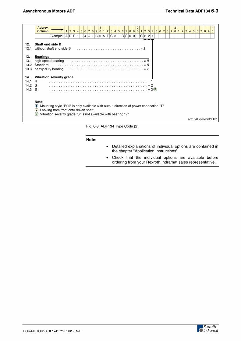
Fig. 6-3: ADF134 Type Code (2)
Note:
• Detailed explanations of individual options are contained inthe chapter "Application Instructions".
• Check that the individual options are available beforeordering from your Rexroth Indramat sales representative.
6-4 Technical Data ADF134 Asynchronous Motors ADF
DOK-MOTOR*-ADF1x4*****-PR01-EN-P
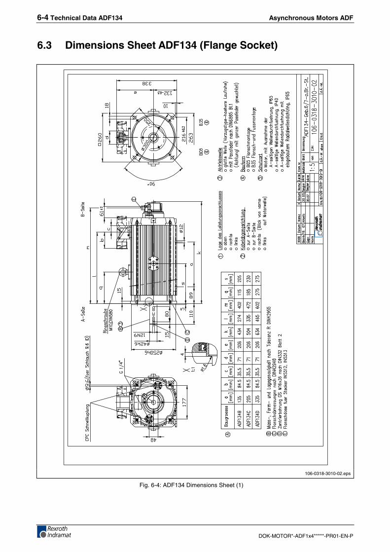
6.3 Dimensions Sheet ADF134 (Flange Socket)
106-0318-3010-02.eps
Fig. 6-4: ADF134 Dimensions Sheet (1)
Asynchronous Motors ADF Technical Data ADF134 6-5
DOK-MOTOR*-ADF1x4*****-PR01-EN-P
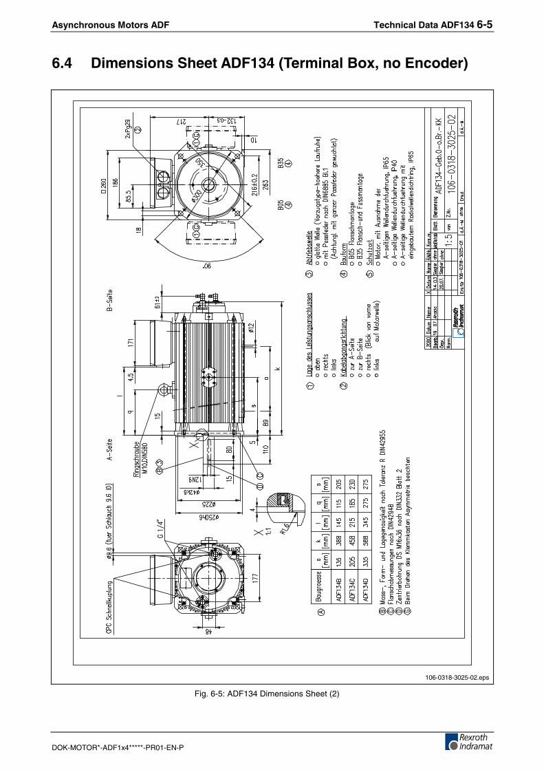
6.4 Dimensions Sheet ADF134 (Terminal Box, no Encoder)
106-0318-3025-02.eps
Fig. 6-5: ADF134 Dimensions Sheet (2)
6-6 Technical Data ADF134 Asynchronous Motors ADF
DOK-MOTOR*-ADF1x4*****-PR01-EN-P
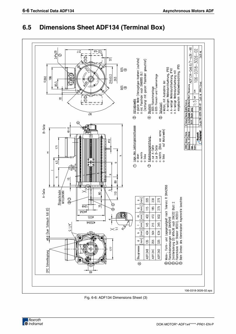
6.5 Dimensions Sheet ADF134 (Terminal Box)
106-0318-3026-02.eps
Fig. 6-6: ADF134 Dimensions Sheet (3)
Asynchronous Motors ADF Technical Data ADF134 6-7
DOK-MOTOR*-ADF1x4*****-PR01-EN-P
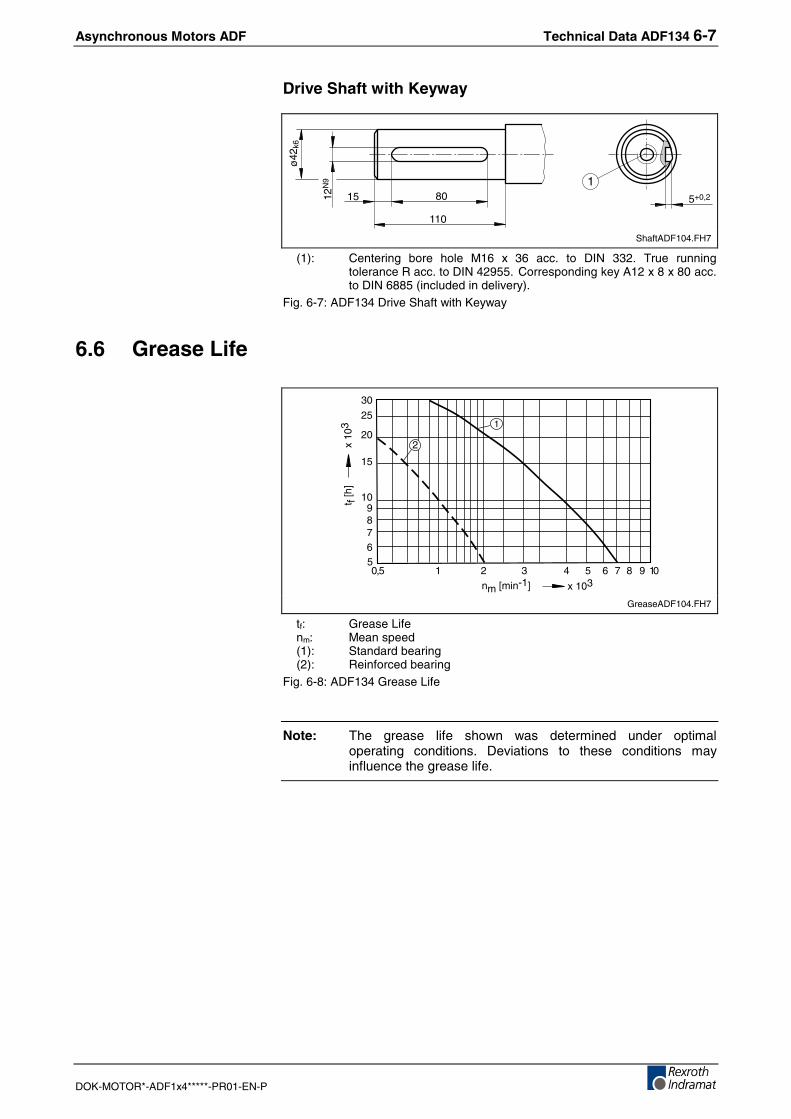
Drive Shaft with Keyway
12N
9
80
110
ø42
k6
15 5+0,2
1
ShaftADF104.FH7
(1): Centering bore hole M16 x 36 acc. to DIN 332. True runningtolerance R acc. to DIN 42955. Corresponding key A12 x 8 x 80 acc.to DIN 6885 (included in delivery).
Fig. 6-7: ADF134 Drive Shaft with Keyway
6.6 Grease Life
5
10
20
6789
15
25
30
0,5 1 2 3 4 65 7 8 9 10
x 103nm [min-1]
t f [h
]x
103
2
1
GreaseADF104.FH7
tf: Grease Lifenm: Mean speed(1): Standard bearing(2): Reinforced bearing
Fig. 6-8: ADF134 Grease Life
Note: The grease life shown was determined under optimaloperating conditions. Deviations to these conditions mayinfluence the grease life.
6-8 Technical Data ADF134 Asynchronous Motors ADF
DOK-MOTOR*-ADF1x4*****-PR01-EN-P
6.7 Shaft Load
X1
X
Fr
Fa
0
1
2
3
4
5
6
0 20 40 60 80 100
0
2
4
6
20 40 60 100
8
10
12
14
nm=7500 min-1
Type "V"
Type "N"
nm = 500 min-1
nm = 1000 min-1
nm = 2000 min-1
nm = 4000 min-1
nm = 8000 min-1
80
Fr
[kN
]
X [mm]
2
Fr
[kN
]
X [mm]
nm=4000 min-1
nm=2000 min-1
nm=1000 min-1
nm=500 min-1
2
1
LoadADF134.FH7
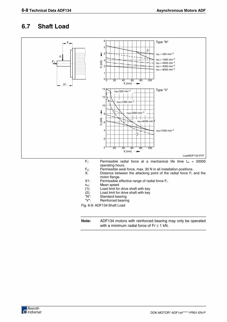
Fr: Permissible radial force at a mechanical life time Lh = 20000operating hours.
Fa: Permissible axial force. max. 30 N in all installation positions.X: Distance between the attacking point of the radial force Fr and the
motor flange.X1: Permissible effective range of radial force Fr.nm: Mean speed(1): Load limit for drive shaft with key(2): Load limit for drive shaft with key"N": Standard bearing"V": Reinforced bearing
Fig. 6-9: ADF134:Shaft Load
Note: ADF134 motors with reinforced bearing may only be operatedwith a minimum radial force of Fr ≥ 1 kN.
Asynchronous Motors ADF Technical Data ADF164 7-1
DOK-MOTOR*-ADF1x4*****-PR01-EN-P
7 Technical Data ADF164
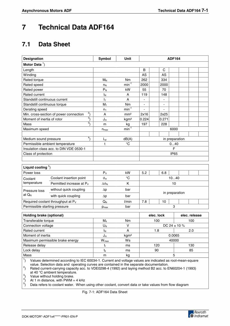
7.1 Data Sheet
Designation Symbol Unit ADF164
Motor Data 1)
Length B CWinding AS ASRated torque MN Nm 262 334Rated speed nN min-1 2000 2000Rated power PN kW 55 70Rated current IN A 119 148Standstill continuous current I1 A - -Standstill continuous torque M1 Nm - -Derating speed n1 min-1 - -Min. cross-section of power connection 2) A mm² 2x16 2x25Moment of inertia of rotor 3) Jm kgm² 0.224 0.271Mass 3) m kg 197 228Maximum speed nmax min-1 6000
Medium sound pressure 4) Lp dB(A) in preparationPermissible ambient temperature t °C 0...40Insulation class acc. to DIN VDE 0530-1 FClass of protection IP65
Liquid cooling 5)
Power loss PV kW 5.2 6.8
Coolant insertion point ϑin °C 10...40Coolanttemperature Permitted increase at PV ∆ϑN K 10
without quick coupling ∆p barPressure lossat QN with quick coupling ∆p bar
in preparation
Required coolant throughput at PV QN l/min 7.8 10Permissible starting pressure pmax bar 3
Holding brake (optional) elec. lock elec. release
Transferable torque M4 Nm 100 100Connection voltage UN V DC 24 ± 10 %Rated current IN A 1.8 2.0Moment of inertia Jm kgm² 0.0065Maximum permissible brake energy Wmax Ws 40000Release delay tl ms 120 130Lock delay tk ms 90 85Mass m kg 51) Values determined according to IEC 60034-1. Current and voltage values are indicated as root-mean-square
value. Selection data and operating curves are contained in the separate documentation.2) Rated current-carrying capacity acc. to VDE0298-4 (1992) and laying method B2 acc. to EN60204-1 (1993)
at 40 °C ambient temperature.3) Value without holding brake.4) At 1 m distance, with PWM = 4 kHz5) Data refers to coolant water.´When using other coolant, convert data or take values from flow diagram
Fig. 7-1: ADF164 Data Sheet
7-2 Technical Data ADF164 Asynchronous Motors ADF
DOK-MOTOR*-ADF1x4*****-PR01-EN-P
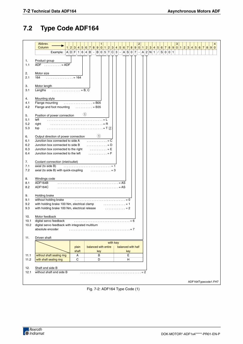
7.2 Type Code ADF164
1. Product group1.1 ADF . . . . . . . . . . = ADF
2. Motor size2.1 164 . . . . . . . . . . . . . . . . = 164
3. Motor length3.1 Lengths . . . . . . . . . . . . . . . . . = B, C
4. Mounting style4.1 Flange mounting . . . . . . . . . . . . . . . . . = B054.2 Flange and foot mounting . . . . . . . . . . = B35
5. Position of power connection5.1 left . . . . . . . . . . . . . . . . . . . . . . . . . . . . . . . . . = L5.2 right . . . . . . . . . . . . . . . . . . . . . . . . . . . . . . . = R5.3 top . . . . . . . . . . . . . . . . . . . . . . . . . . . . . . . . . = T
6. Output direction of power connection6.1 Junction box connected to side A . . . . . . . . . . . . = C6.2 Junction box connected to side B . . . . . . . . . . . . = D6.3 Junction box connected to the right . . . . . . . . . . = E6.4 Junction box connected to the left . . . . . . . . . . . = F
7. Coolant connection (inlet/outlet)7.1 axial (to side B) . . . . . . . . . . . . . . . . . . . . . . . . . . . . = 17.2 axial (to side B) with quick-coupling . . . . . . . . . . . . = 3
8. Windings code8.1 ADF164B . . . . . . . . . . . . . . . . . . . . . . . . . . . . . . . . . . . . = AS8.2 ADF164C . . . . . . . . . . . . . . . . . . . . . . . . . . . . . . . . . . . . = AS
9. Holding brake9.1 without holding brake . . . . . . . . . . . . . . . . . . . . . . . . . . . . . . = 09.2 with holding brake 100 Nm, electrical clamp . . . . . . . . . . . . . = 19.3 with holding brake 100 Nm, electrical release . . . . . . . . . . . . = 2
10. Motor feedback10.1 digital servo feedback . . . . . . . . . . . . . . . . . . . . . . . . . . . . . . . . . = 610.2 digital servo feedback with integrated multiturn
absolute encoder . . . . . . . . . . . . . . . . . . . . . . . . . . . . . . . . . . . . = 7
11. Driven shaft
with keyplain balanced with entire balanced with halfshaft key key
11.1 without shaft sealing ring A B E11.2 with shaft sealing ring C D H
12. Shaft end side B12.1 without shaft end side B . . . . . . . . . . . . . . . . . . . . . . . . . . . . . . . . . . . . = 2
1 2 3 4 6 7 8 9105 1 2 3 4 6 7 8 9
205 1 2 3 4 6 7 8 9
305 1 2 3 4 6 7 8 9
405
Example:
Abbrev.Column
A D F 1 6 4 B - B 0 5 T C 3 - A S 0 7 - A 2 N 1 / S 0 0 1
1
1
2
ADF164Typecode1.FH7
Fig. 7-2: ADF164 Type Code (1)
Asynchronous Motors ADF Technical Data ADF164 7-3
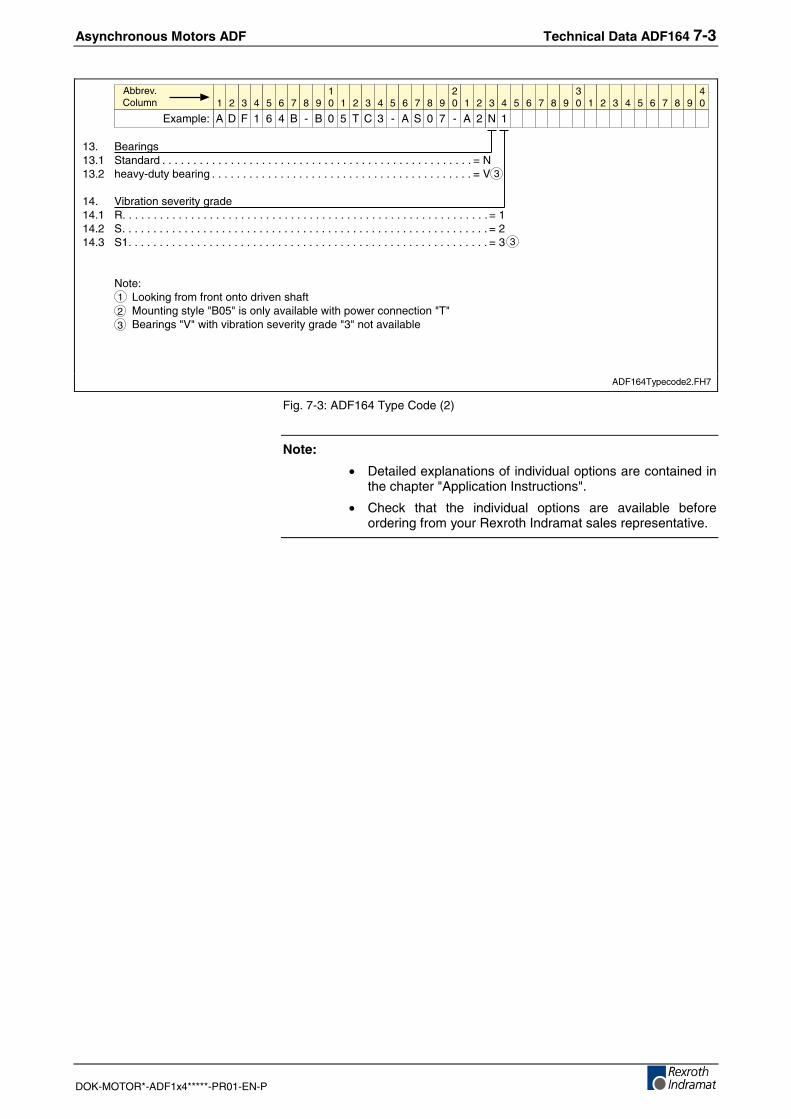
DOK-MOTOR*-ADF1x4*****-PR01-EN-P
13. Bearings13.1 Standard . . . . . . . . . . . . . . . . . . . . . . . . . . . . . . . . . . . . . . . . . . . . . . . . . . = N13.2 heavy-duty bearing . . . . . . . . . . . . . . . . . . . . . . . . . . . . . . . . . . . . . . . . . . = V
14. Vibration severity grade14.1 R. . . . . . . . . . . . . . . . . . . . . . . . . . . . . . . . . . . . . . . . . . . . . . . . . . . . . . . . . . . = 114.2 S. . . . . . . . . . . . . . . . . . . . . . . . . . . . . . . . . . . . . . . . . . . . . . . . . . . . . . . . . . . = 214.3 S1. . . . . . . . . . . . . . . . . . . . . . . . . . . . . . . . . . . . . . . . . . . . . . . . . . . . . . . . . . = 3
Note:Looking from front onto driven shaftMounting style "B05" is only available with power connection "T"Bearings "V" with vibration severity grade "3" not available
1 2 3 4 6 7 8 9105 1 2 3 4 6 7 8 9
205 1 2 3 4 6 7 8 9
305 1 2 3 4 6 7 8 9
405
Example:
Abbrev.Column
A D F 1 6 4 B - B 0 5 T C 3 - A S 0 7 - A 2 N 1
1
3
3
23
ADF164Typecode2.FH7
Fig. 7-3: ADF164 Type Code (2)
Note:
• Detailed explanations of individual options are contained inthe chapter "Application Instructions".
• Check that the individual options are available beforeordering from your Rexroth Indramat sales representative.
7-4 Technical Data ADF164 Asynchronous Motors ADF
DOK-MOTOR*-ADF1x4*****-PR01-EN-P
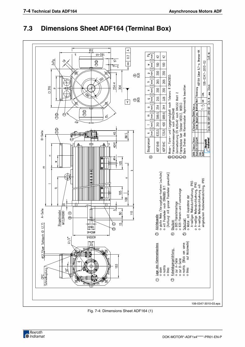
7.3 Dimensions Sheet ADF164 (Terminal Box)
106-0347-3010-03.eps
Fig. 7-4: Dimensions Sheet ADF164 (1)
Asynchronous Motors ADF Technical Data ADF164 7-5
DOK-MOTOR*-ADF1x4*****-PR01-EN-P
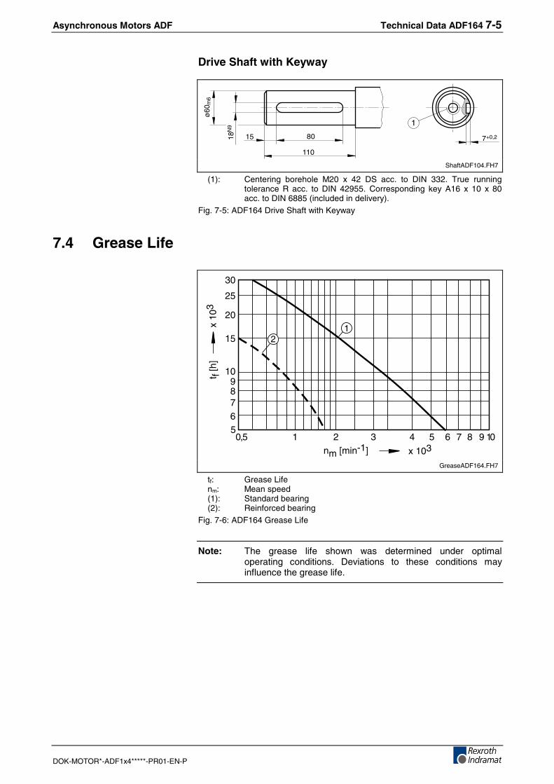
Drive Shaft with Keyway
18N
9
80
110
ø60
m6
15 7+0,2
1
ShaftADF104.FH7
(1): Centering borehole M20 x 42 DS acc. to DIN 332. True runningtolerance R acc. to DIN 42955. Corresponding key A16 x 10 x 80acc. to DIN 6885 (included in delivery).
Fig. 7-5: ADF164 Drive Shaft with Keyway
7.4 Grease Life
5
10
20
6789
15
25
30
0,5 1 2 3 4 65 7 8 9 10
x 103
t f [h
]x
103
nm [min-1]
21
GreaseADF164.FH7
tf: Grease Lifenm: Mean speed(1): Standard bearing(2): Reinforced bearing
Fig. 7-6: ADF164 Grease Life
Note: The grease life shown was determined under optimaloperating conditions. Deviations to these conditions mayinfluence the grease life.
7-6 Technical Data ADF164 Asynchronous Motors ADF
DOK-MOTOR*-ADF1x4*****-PR01-EN-P
7.5 Shaft Load
0
2
4
6
8
10
12
14
16
18
20
0
2
4
6
8
0 20 40 60 80 100
X1
X
Fr
Fa
Type "N"
nm = 500 min-1
nm = 1000 min-1
nm = 2000 min-1
nm = 4000 min-1
nm = 6000 min-1Fr
[kN
]
X [mm]
0 20 40 60 80 100
Fr
[kN
]
X [mm]
nm=6000 min-1
Type "V"
nm=4000 min-1
nm=500 min-1
21
nm=1000 min-1
nm=2000 min-1
LoadADF164.FH7
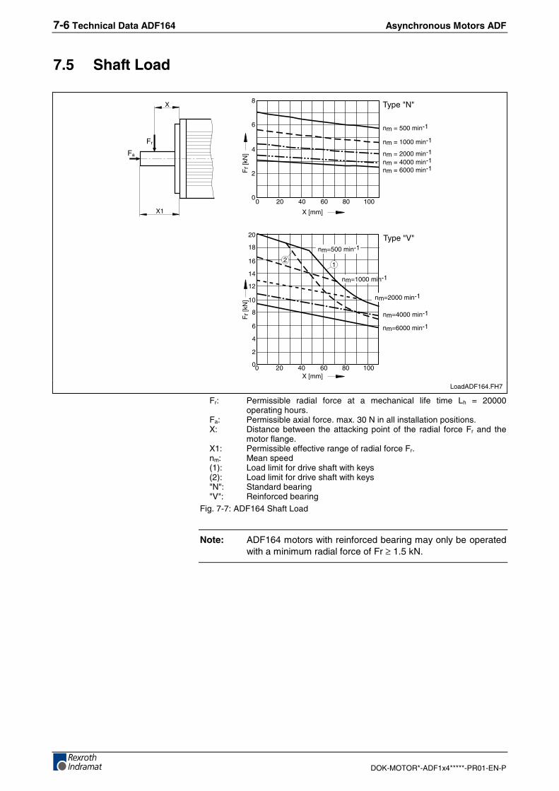
Fr: Permissible radial force at a mechanical life time Lh = 20000operating hours.
Fa: Permissible axial force. max. 30 N in all installation positions.X: Distance between the attacking point of the radial force Fr and the
motor flange.X1: Permissible effective range of radial force Fr.nm: Mean speed(1): Load limit for drive shaft with keys(2): Load limit for drive shaft with keys"N": Standard bearing"V": Reinforced bearing
Fig. 7-7: ADF164 Shaft Load
Note: ADF164 motors with reinforced bearing may only be operatedwith a minimum radial force of Fr ≥ 1.5 kN.

Asynchronous Motors ADF Technical Data ADF184 8-1
DOK-MOTOR*-ADF1x4*****-PR01-EN-P
8 Technical Data ADF184
8.1 Data Sheet
Designation Symbol Unit ADF184
Motor Data 1)
Length C DWinding DS DSRated torque MN Nm 320 390Rated speed nN min-1 2000 2000Rated power PN kW 67 81.7Rated current IN A 154.3 162Standstill continuous current I1 A - -Standstill continuous torque M1 Nm - -Derating speed n1 min-1 - -Min. cross-section of power connection 2) A mm² 2 x 25 2 x 25Moment of inertia of rotor 3) Jm kgm² 0.49 i.V.Mass 3) m kg 312 470Maximum speed nmax min-1 5400 5400
Medium sound pressure 4) Lp dB(A) in preparationPermissible ambient temperature t °C 0...40Insulation class acc. to DIN VDE 0530-1 FClass of protection IP65
Liquid cooling 5)
Power loss PV kW 5.4 6.1
Coolant insertion point ϑin °C 10...40Coolanttemperature Permissible increase at PVN ∆ϑN K 10
without quick coupling ∆p bar 0.3 0.35Pressure lossat QN with quick coupling ∆p bar 0.4 0.45
Required coolant throughput at PV QN l/min 7.9 8.7Permissible starting pressure pmax bar 3
Holding brake (optional)
Transferable torque M4 NmConnection voltage UN VRated current IN AMoment of inertia Jm kgm²Maximum permissible brake energy Wmax WsRelease delay tl msLock delay tk msMass m kg
not available
1) Values determined according to IEC 60034-1. Current and voltage values are indicated as root-mean-squarevalue. Selection data and operating curves are contained in the separate documentation.
2) Rated current-carrying capacity acc. to VDE0298-4 (1992) and laying method B2 acc. to EN60204-1 (1993)at 40 °C ambient temperature.
3) Value without holding brake.4) At 1 m distance, with PWM = 4 kHz5) Data refers to coolant water. When using other coolant, convert data or take values from flow diagram
Fig. 8-1: ADF184 Data Sheet
8-2 Technical Data ADF184 Asynchronous Motors ADF
DOK-MOTOR*-ADF1x4*****-PR01-EN-P
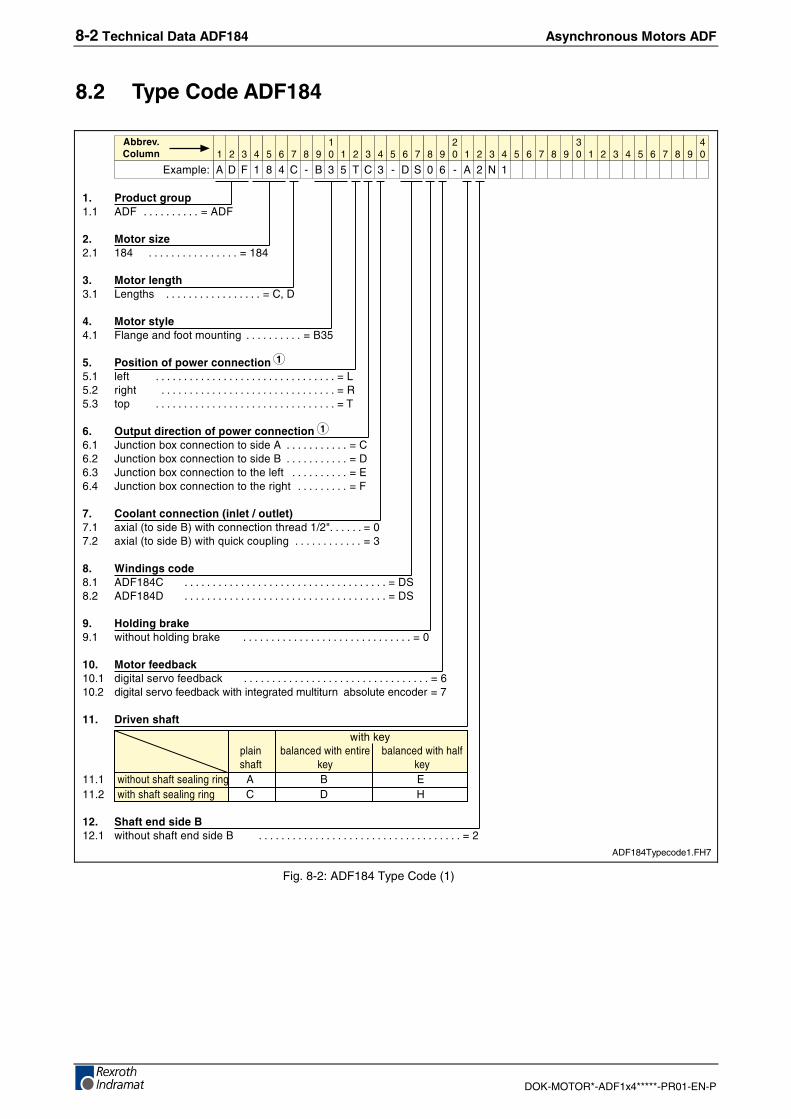
8.2 Type Code ADF184
�� ���������!��� &'( ������������������� ��&'(
�� ��� ������ ��� ������������������������������� �����
�� ����������� ������� ��������������������������������� ��)-�'
�� ��� ������ (%�������������.����� ������������������� ��+�!
�� � ���� �!"����������!�� %��� ��������������������������������������������������������������� ���!�� ����� ������������������������������������������������������������� ���!�� �$ ��������������������������������������������������������������� ��,
#� $�!���������� �!"������������� 1.�2����3#�2���2�����������& ��������������������� ��)��� 1.�2����3#�2���2�����������+ ��������������������� ��'��� 1.�2����3#�2���2����������%��� ������������������� ��"��� 1.�2����3#�2���2��������������� ����������������� ��(
%� �������������&�����'����(��� �#��%�4�������+5�0����2���2������������7�8����������� �� ��� �#��%�4�������+5�0����=.�2��2.$%��� ����������������������� ���
)� *������ ������� &'(���) ����������������������������������������������������������������������� ��'���� &'(���'� ����������������������������������������������������������������������� ��'�
+� ,���������-���� 0���.���%�����3���� ����������������������������������������������������������� ��
�.� ��� ������-� �� ������%����������3�2� ����������������������������������������������������������������� ���� �� ������%����������3�2��0����������������.%���.��� �3�%.�����2��� ���
��� /������ ��
0������9$%��� 3�%��2���0���������� 3�%��2���0������%�
� ����� ��9 ��9���� �0���.�����������%�������� & + "���� �0�������������%�������� ) ' :
��� 0�� ����� ����1���� 0���.�����������������+ ����������������������������������������������������������������������� ���
� � � � � � � �� ! � � � � � � � �
� ! � � � � � � � �
� ! � � � � � � � �
� !
"#��$%�
������������
& ' ( � � � ) * + � ! , ) � * ' � � * & � �
�
�
ADF184Typecode1.FH7
Fig. 8-2: ADF184 Type Code (1)
Asynchronous Motors ADF Technical Data ADF184 8-3
DOK-MOTOR*-ADF1x4*****-PR01-EN-P
� � � � � � � �� ! � � � � � � � �
� ! � � � � � � � �
� ! � � � � � � � �
� !
"#��$%�
������������
& ' ( � � � ) * + � ! , ) � * ' � � * & � �
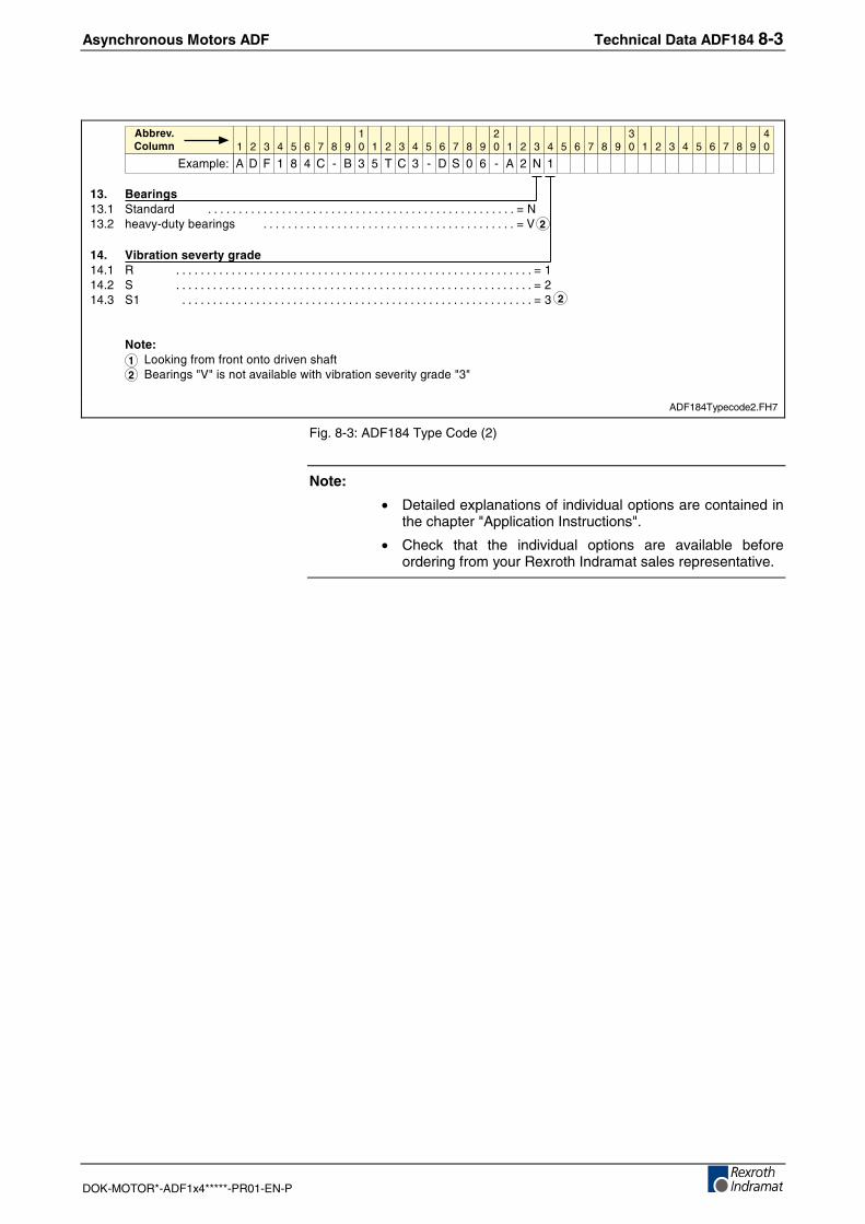
��� 1������ ���� �������� ��������������������������������������������������������������������������������������������������� ������ ����9*�.�9�3������� ��������������������������������������������������������������������������������� ��;
��� �������� ��������������� � ������������������������������������������������������������������������������������������������������������������� ������� � ������������������������������������������������������������������������������������������������������������������� ������� �� ����������������������������������������������������������������������������������������������������������������� ���
2�3������������������������������+��������8;8�����������%�3%��0������3�������������9�������8�8
�
�
�
�
ADF184Typecode2.FH7
Fig. 8-3: ADF184 Type Code (2)
Note:
• Detailed explanations of individual options are contained inthe chapter "Application Instructions".
• Check that the individual options are available beforeordering from your Rexroth Indramat sales representative.
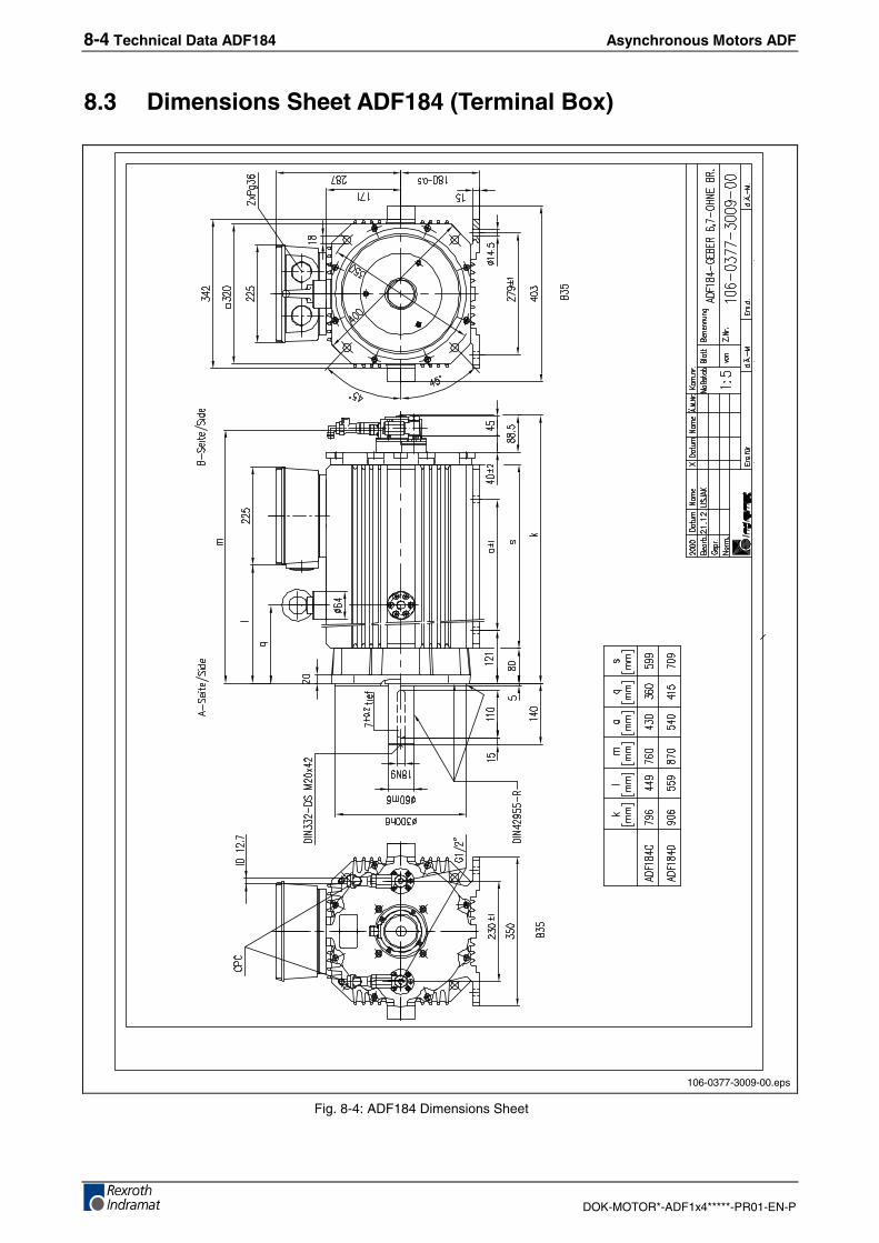
8-4 Technical Data ADF184 Asynchronous Motors ADF
DOK-MOTOR*-ADF1x4*****-PR01-EN-P
8.3 Dimensions Sheet ADF184 (Terminal Box)
106-0377-3009-00.eps
Fig. 8-4: ADF184 Dimensions Sheet

Asynchronous Motors ADF Technical Data ADF184 8-5
DOK-MOTOR*-ADF1x4*****-PR01-EN-P
Drive Shaft with Keyway
18N
9
110
140
ø60
m6
15 7+0,2
1
ShaftADF184.FH7
(1): Centering borehole M20 x 42 DS acc. to DIN 332. True runningtolerance R acc. to DIN 42955. Corresponding key A18 x 11 x 110acc. to DIN 6885 (included in delivery).
Fig. 8-5: ADF184 Drive Shaft with Key
8.4 Grease Life
5
10
20
6789
15
25
30
0,5 1 2 3 4 65 7 8 910
t f [h
]x
103
x 103nm [min-1]
2
1
GreaseADF184.FH7
tf: Grease Lifenm: Mean speed(1): Standard bearing(2): Reinforced bearing
Fig. 8-6: ADF184 Grease Life
Note: The grease life shown was determined under optimaloperating conditions. Deviations to these conditions mayinfluence the grease life.
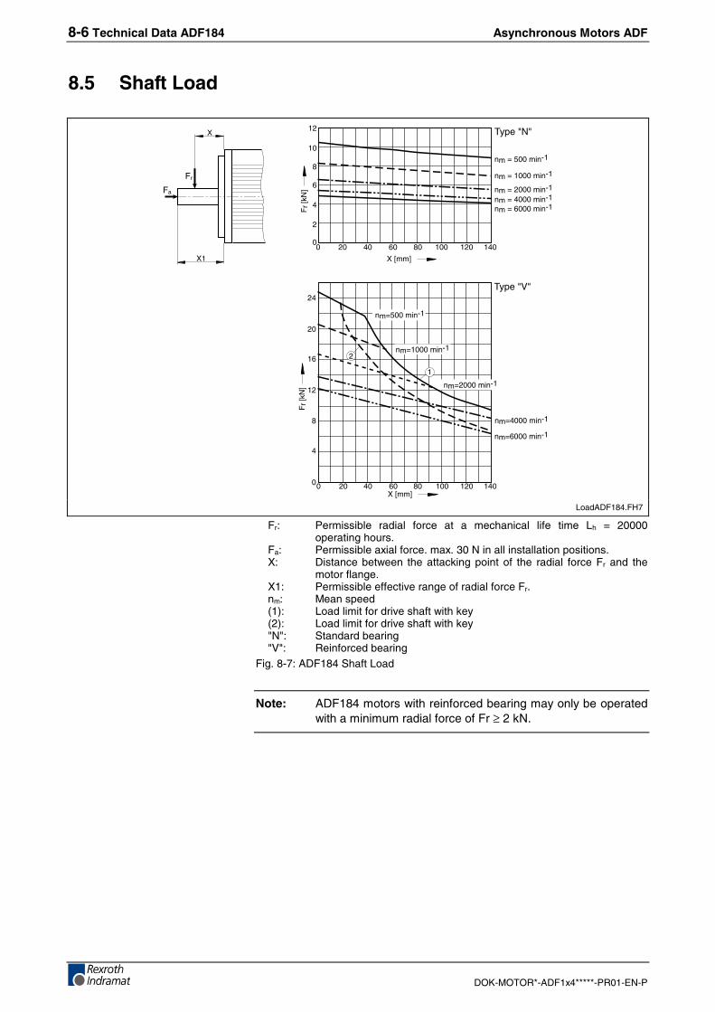
8-6 Technical Data ADF184 Asynchronous Motors ADF
DOK-MOTOR*-ADF1x4*****-PR01-EN-P
8.5 Shaft Load
0 20 40 80 100 120 140
2
4
6
8
10
12
0
0
4
8
12
16
20
24
Type "N"
nm = 500 min-1
nm = 1000 min-1
nm = 2000 min-1
nm = 4000 min-1
nm = 6000 min-1
60
X1
X
Fr
Fa
Fr
[kN
]
X [mm]
0 20 40 60 80 100 120 140
Fr
[kN
]
X [mm]
nm=6000 min-1
nm=4000 min-1
nm=500 min-1
nm=2000 min-1
nm=1000 min-1
Type "V"
2
1
LoadADF184.FH7
Fr: Permissible radial force at a mechanical life time Lh = 20000operating hours.
Fa: Permissible axial force. max. 30 N in all installation positions.X: Distance between the attacking point of the radial force Fr and the
motor flange.X1: Permissible effective range of radial force Fr.nm: Mean speed(1): Load limit for drive shaft with key(2): Load limit for drive shaft with key"N": Standard bearing"V": Reinforced bearing
Fig. 8-7: ADF184 Shaft Load
Note: ADF184 motors with reinforced bearing may only be operatedwith a minimum radial force of Fr ≥ 2 kN.
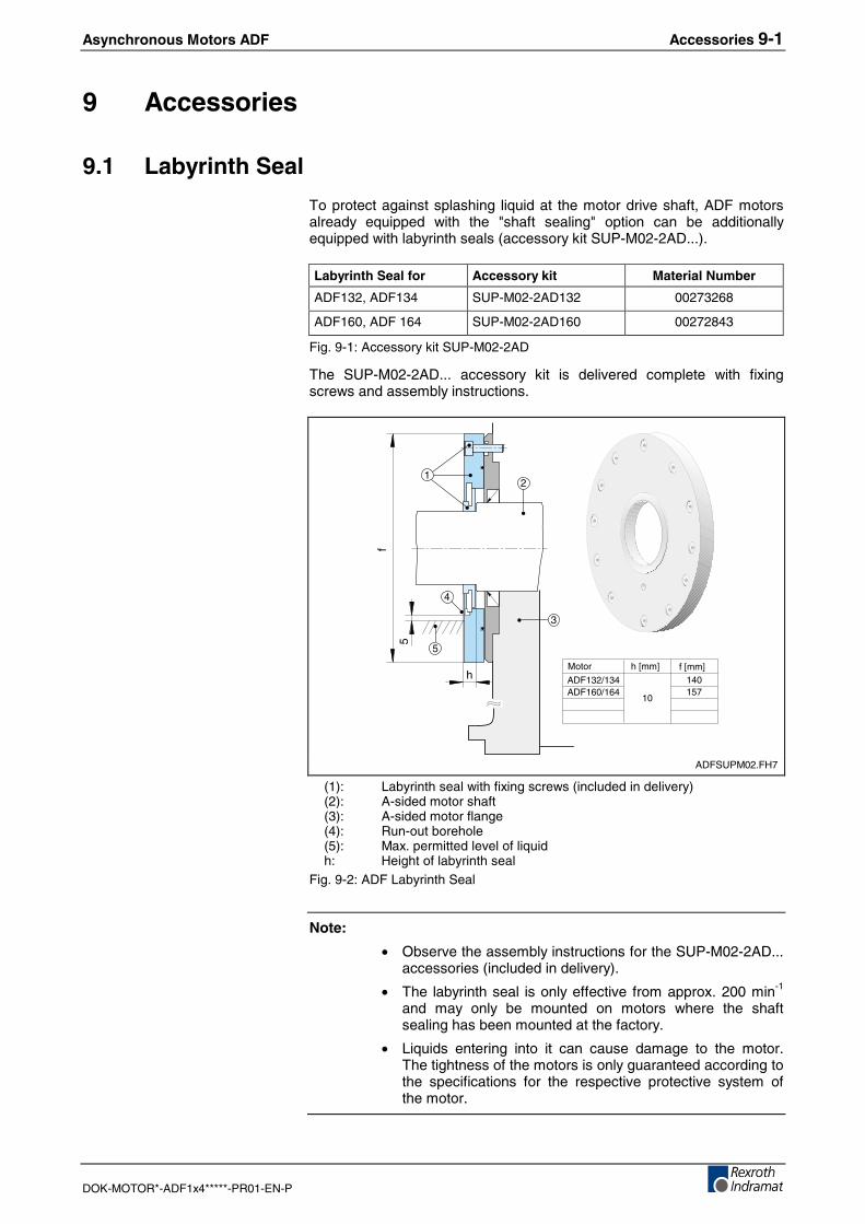
Asynchronous Motors ADF Accessories 9-1
DOK-MOTOR*-ADF1x4*****-PR01-EN-P
9 Accessories
9.1 Labyrinth Seal
To protect against splashing liquid at the motor drive shaft, ADF motorsalready equipped with the "shaft sealing" option can be additionallyequipped with labyrinth seals (accessory kit SUP-M02-2AD...).
Labyrinth Seal for Accessory kit Material Number
ADF132, ADF134 SUP-M02-2AD132 00273268
ADF160, ADF 164 SUP-M02-2AD160 00272843
Fig. 9-1: Accessory kit SUP-M02-2AD
The SUP-M02-2AD... accessory kit is delivered complete with fixingscrews and assembly instructions.
h
5
1
4
5
3
f
ADF132/134ADF160/164
Motor h [mm]
10
f [mm]140157
2
ADFSUPM02.FH7
(1): Labyrinth seal with fixing screws (included in delivery)(2): A-sided motor shaft(3): A-sided motor flange(4): Run-out borehole(5): Max. permitted level of liquidh: Height of labyrinth seal
Fig. 9-2: ADF Labyrinth Seal
Note:
• Observe the assembly instructions for the SUP-M02-2AD...accessories (included in delivery).
• The labyrinth seal is only effective from approx. 200 min-1
and may only be mounted on motors where the shaftsealing has been mounted at the factory.
• Liquids entering into it can cause damage to the motor.The tightness of the motors is only guaranteed according tothe specifications for the respective protective system ofthe motor.
9-2 Accessories Asynchronous Motors ADF
DOK-MOTOR*-ADF1x4*****-PR01-EN-P
Asynchronous Motors ADF Connections 10-1
DOK-MOTOR*-ADF1x4*****-PR01-EN-P
10 Connections
10.1 Notes
The user can choose between ready-made cables from REXROTHINDRAMAT or he can assemble the required cables himself.
REXROTH INDRAMAT provides a comprehensive range of assembledcables, plugs and sockets that have been optimally adapted to theproducts and to the most varied requirements.
The decisive advantages of ready-made cables from REXROTHINDRAMAT are:
• Cable is completely ready for connection without any further workbeing required
• Cable is designed to withhold strain from continuous bending
• Resistance against mineral oils, grease and bio oils, hydrolysis-proof,free of silicon and halogen, low adhesion
• Certification acc. to UL and CSA
• Burning characteristics fulfil requirements of VDE0472-804
• Observes the EMC regulations
• Protective class up to IP67
Note: Please observe that self-assembled cable or cablesystems from other manufacturers may not meet theserequirements under certain conditions.
Rexroth Indramat does not accept any responsibility forfaults or damages arising from this.
Additional information is available ...
• on selection of power cable and encoder cable for ADF motors in thedocumentation "Connection Cable for DIAX04, ECODRIVE03 andPOWERDRIVE, Selection Data", Mat.No. 00280894.
• on assembling of cables and plugs as well as technical data in thedocumentation "Indramat Connection Technology, Assembly andTools...", Mat.No. 00280895.
• on dimensioning of cooling systems for ADF motors in thedocumentation "Liquid Cooling of Indramat Drive Components",Mat.No. 00265836.
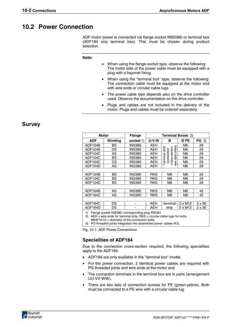
10-2 Connections Asynchronous Motors ADF
DOK-MOTOR*-ADF1x4*****-PR01-EN-P
10.2 Power Connection
ADF motor power is connected via flange socket INS0380 or terminal box(ADF184 only terminal box). This must be chosen during productselection.
Note:
• When using the flange socket type, observe the following:The motor side of the power cable must be equipped with aplug with a bayonet fixing.
• When using the "terminal box" type, observe the following:The connection cable must be equipped at the motor endwith wire ends or circular cable lugs.
• The power cable type depends also on the drive controllerused. Observe the documentation on the drive controller.
• Plugs and cables are not included in the delivery of themotor. Plugs and cables must be ordered separately.
Survey
Motor Flange Terminal Boxes 2)
ADF Winding socket 1) U-V-W Ø Ø PE PG 3)ADF104B BS INS380 AEH M6 29ADF104B DS INS380 AEH M6 29ADF104C AS INS380 AEH M6 29ADF104C BS INS380 AEH M6 29ADF104C CS INS380 AEH M6 29ADF104D AS INS380 AEH
Ter
min
alst
ripC
onne
ctio
ncr
oss-
sect
ion
see
data
shee
t
M6 29
ADF134B BS INS380 RKS M8 M8 29ADF134C BS INS380 RKS M8 M8 29ADF134D BS INS380 RKS M8 M8 29
ADF164B AS INS380 RKS M8 M8 42ADF164C AS INS380 RKS M8 M8 42
ADF184C DS - AEH 2 x M12 2 x 36ADF184D DS - AEH
terminalstrip 2 x M12 2 x 36
1) Flange socket INS380: corresponding plug INS3812) AEH = wire ends for terminal strip. RKS = circular cable lugs for bolts.
M6/8/10/12 = diameter of the connection bolts.3) PG threaded joints integrated into assembled power cables IKG.
Fig. 10-1: ADF Power Connections
Specialities of ADF184Due to the connection cross-section required, the following specialitiesapply to the ADF184:
• ADF184 are only available in the "terminal box" model.
• For the power connection, 2 identical power cables are required withPG threaded joints and wire ends at the motor end.
• The connection terminals in the terminal box are in pairs (arrangementUU-VV-WW).
• There are two sets of connection screws for PE (green-yellow). Bothmust be connected to a PE wire with a circular cable lug.
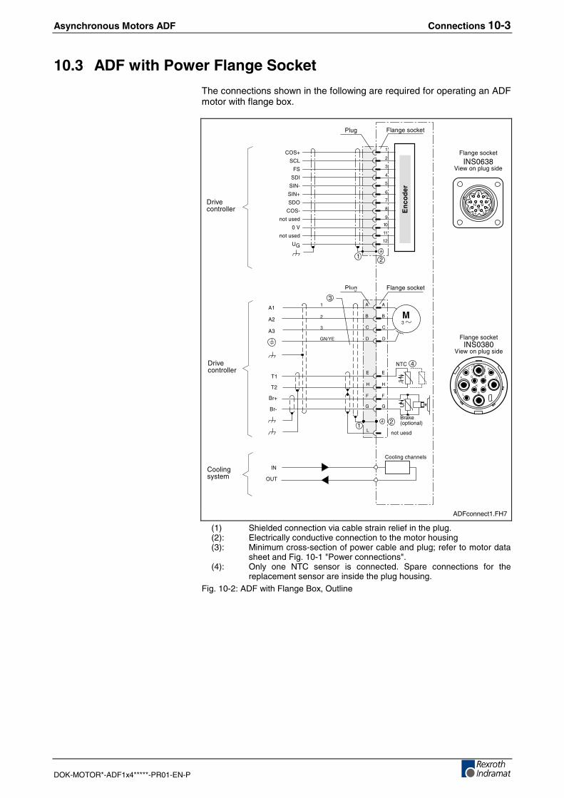
Asynchronous Motors ADF Connections 10-3
DOK-MOTOR*-ADF1x4*****-PR01-EN-P
10.3 ADF with Power Flange Socket
The connections shown in the following are required for operating an ADFmotor with flange box.
(%������2���
>� ���;��0���$%.������
/%.�
4��
���
/%.�
'����2���%%��
&
+
)
&�
&�
&�
��
+����4$����%5
?
"
:
(
�
�
�
@7A"
+�*
+�B
'
&
+
)
'
"
:
(
@
���.���
'����2���%%��
>
C?,
)%����9����
,�
,�
,)
�
�
&
+
)@
( :
"
'
1D
�
(%������2���>� ��
;��0���$%.������
(%������2���
(%������2���
�
��
�
�
�
�
!
�
�
�
�
�
��
��
)C�B
�)�
(�
�'>
�>*
�>B
�'C
)C�*
���.���
�;
���.���
?@
�
�
�!�
�
�
��
����
�
)%����2�����%�
�
@
�
ADFconnect1.FH7
(1) Shielded connection via cable strain relief in the plug.(2): Electrically conductive connection to the motor housing(3): Minimum cross-section of power cable and plug; refer to motor data
sheet and Fig. 10-1 "Power connections".(4): Only one NTC sensor is connected. Spare connections for the
replacement sensor are inside the plug housing.Fig. 10-2: ADF with Flange Box, Outline
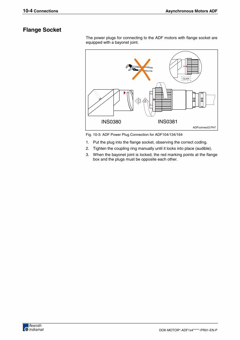
10-4 Connections Asynchronous Motors ADF
DOK-MOTOR*-ADF1x4*****-PR01-EN-P
Flange SocketThe power plugs for connecting to the ADF motors with flange socket areequipped with a bayonet joint.
1
INS0380 INS0381
CLICK
2
ADFconnect3.FH7
Fig. 10-3: ADF Power Plug Connection for ADF104/134/164
1. Put the plug into the flange socket, observing the correct coding.
2. Tighten the coupling ring manually until it locks into place (audible).
3. When the bayonet joint is locked, the red marking points at the flangebox and the plugs must be opposite each other.
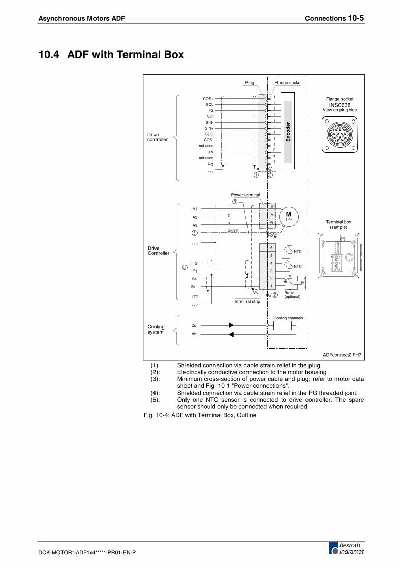
Asynchronous Motors ADF Connections 10-5
DOK-MOTOR*-ADF1x4*****-PR01-EN-P
10.4 ADF with Terminal Box
(%������2���>� ���
;��0���$%.������
/%.�
4��
���
'����)���%%��
&�
&�
&�
��
+����4$����%5
?
�
�
�
@7A"
+�B
+�*
?�
;�
E�
�
�
�
�
'����2���%%��
F.
&3
)%����9����
,�
,�,)
�
�
(%������2���
/0����������%
�
�
�
�
�
!
�
�
�
�
�
��
��
)C�B
�)�
(�
�'>
�>*
�>B
�'C
)C�*
���.���
�;
���.���
?@
�
�
�!�
�
�
��
����
�
)%����2�����%�
,)
,������%�����$
�
�
!
�
!
�
,������%�3#4���$%�5
ADFconnect2.FH7
(1) Shielded connection via cable strain relief in the plug.(2): Electrically conductive connection to the motor housing(3): Minimum cross-section of power cable and plug; refer to motor data
sheet and Fig. 10-1 "Power connections".(4): Shielded connection via cable strain relief in the PG threaded joint.(5): Only one NTC sensor is connected to drive controller. The spare
sensor should only be connected when required.Fig. 10-4: ADF with Terminal Box, Outline
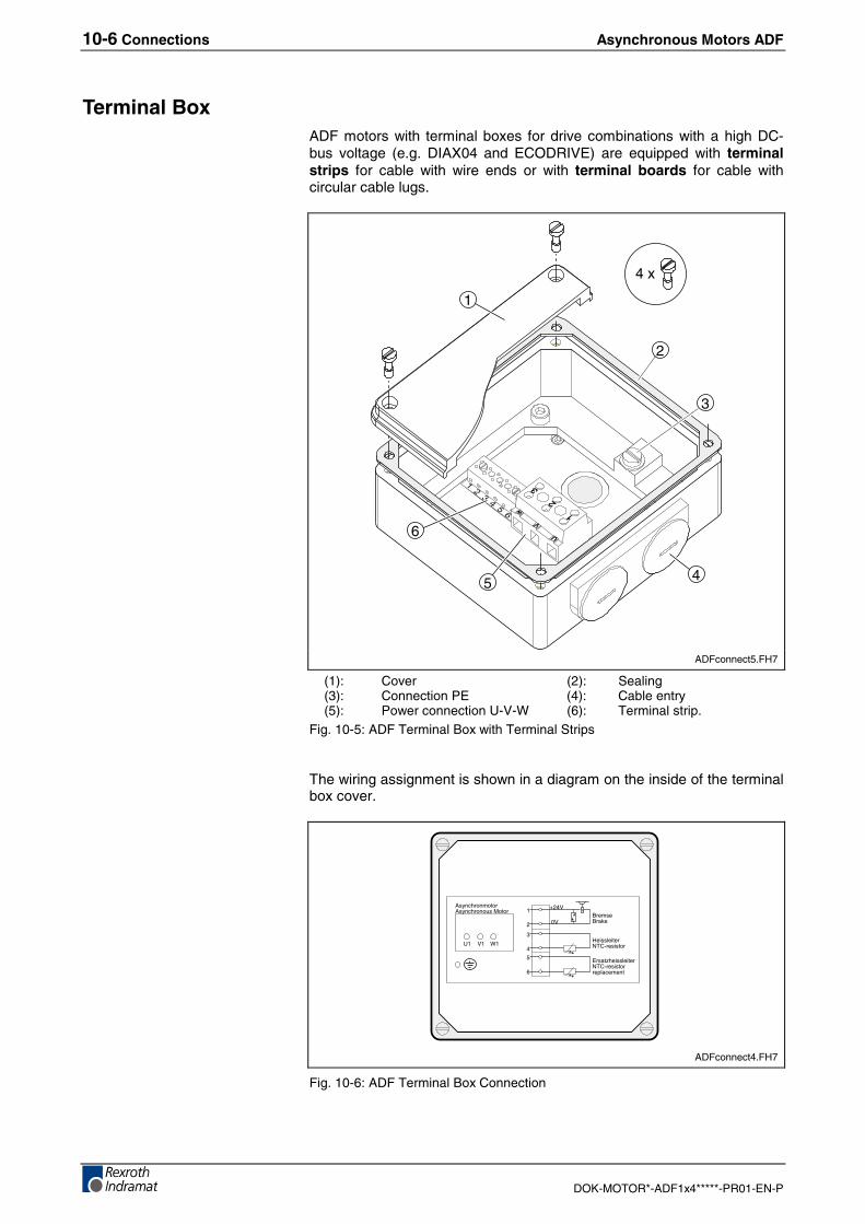
10-6 Connections Asynchronous Motors ADF
DOK-MOTOR*-ADF1x4*****-PR01-EN-P
Terminal BoxADF motors with terminal boxes for drive combinations with a high DC-bus voltage (e.g. DIAX04 and ECODRIVE) are equipped with terminalstrips for cable with wire ends or with terminal boards for cable withcircular cable lugs.
1
2
4
6
5
3
4 x
ADFconnect5.FH7
(1): Cover (2): Sealing(3): Connection PE (4): Cable entry(5): Power connection U-V-W (6): Terminal strip.
Fig. 10-5: ADF Terminal Box with Terminal Strips
The wiring assignment is shown in a diagram on the inside of the terminalbox cover.
U1 V1 W1
+24V
0VBremseBrake
HeissleiterNTC-resistor
ErsatzheissleiterNTC-resistorreplacement
AsynchronmotorAsynchronous Motor 1
2
3
4
5
6
ADFconnect4.FH7
Fig. 10-6: ADF Terminal Box Connection
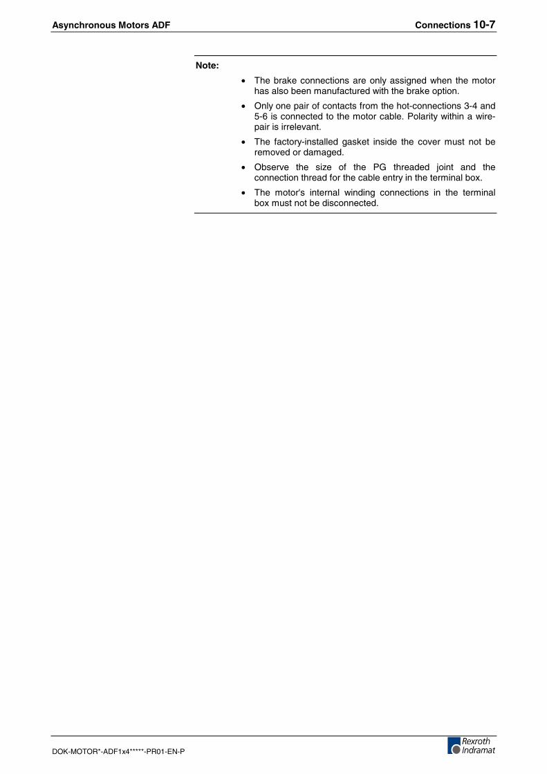
Asynchronous Motors ADF Connections 10-7
DOK-MOTOR*-ADF1x4*****-PR01-EN-P
Note:
• The brake connections are only assigned when the motorhas also been manufactured with the brake option.
• Only one pair of contacts from the hot-connections 3-4 and5-6 is connected to the motor cable. Polarity within a wire-pair is irrelevant.
• The factory-installed gasket inside the cover must not beremoved or damaged.
• Observe the size of the PG threaded joint and theconnection thread for the cable entry in the terminal box.
• The motor's internal winding connections in the terminalbox must not be disconnected.
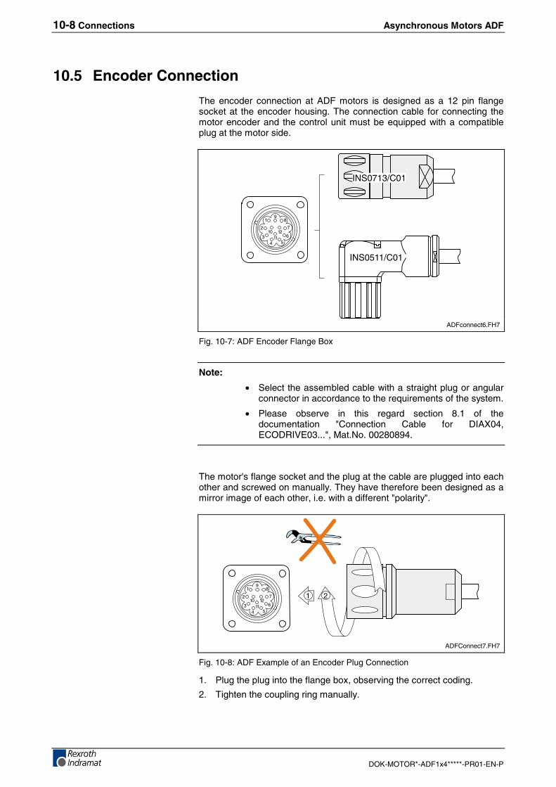
10-8 Connections Asynchronous Motors ADF
DOK-MOTOR*-ADF1x4*****-PR01-EN-P
10.5 Encoder Connection
The encoder connection at ADF motors is designed as a 12 pin flangesocket at the encoder housing. The connection cable for connecting themotor encoder and the control unit must be equipped with a compatibleplug at the motor side.
8
7
654
3
2
19
1211
10
INS0713/C01
INS0511/C01
ADFconnect6.FH7
Fig. 10-7: ADF Encoder Flange Box
Note:
• Select the assembled cable with a straight plug or angularconnector in accordance to the requirements of the system.
• Please observe in this regard section 8.1 of thedocumentation "Connection Cable for DIAX04,ECODRIVE03...", Mat.No. 00280894.
The motor's flange socket and the plug at the cable are plugged into eachother and screwed on manually. They have therefore been designed as amirror image of each other, i.e. with a different "polarity".
8
7
654
3
2
19
1211
101 2
ADFConnect7.FH7
Fig. 10-8: ADF Example of an Encoder Plug Connection
1. Plug the plug into the flange box, observing the correct coding.
2. Tighten the coupling ring manually.
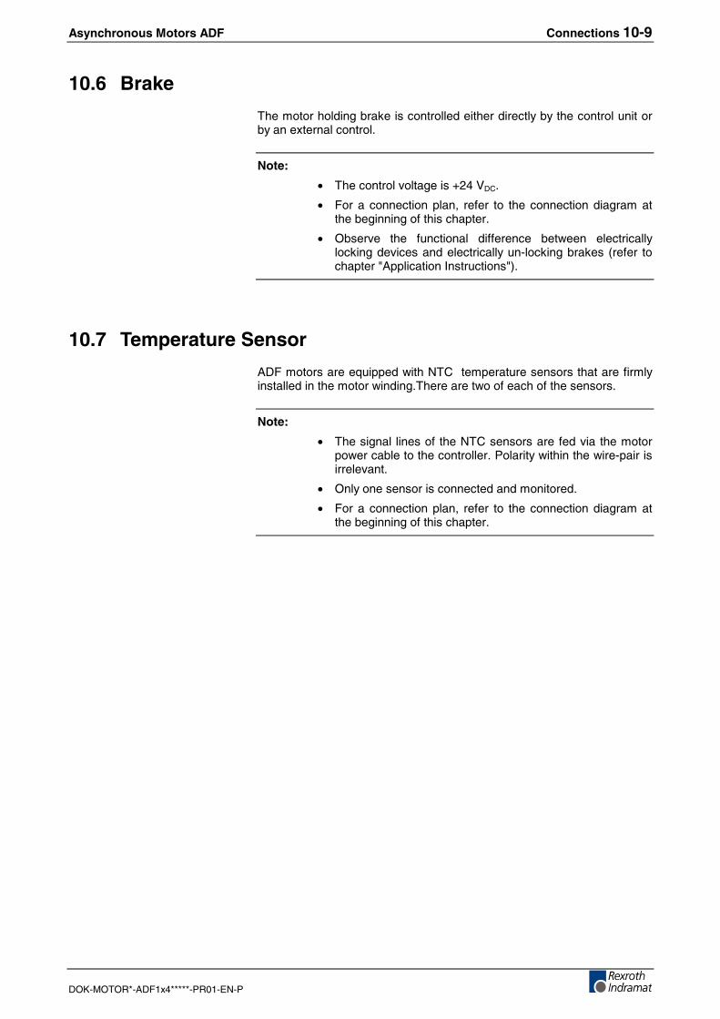
Asynchronous Motors ADF Connections 10-9
DOK-MOTOR*-ADF1x4*****-PR01-EN-P
10.6 Brake
The motor holding brake is controlled either directly by the control unit orby an external control.
Note:
• The control voltage is +24 VDC.
• For a connection plan, refer to the connection diagram atthe beginning of this chapter.
• Observe the functional difference between electricallylocking devices and electrically un-locking brakes (refer tochapter "Application Instructions").
10.7 Temperature Sensor
ADF motors are equipped with NTC temperature sensors that are firmlyinstalled in the motor winding.There are two of each of the sensors.
Note:
• The signal lines of the NTC sensors are fed via the motorpower cable to the controller. Polarity within the wire-pair isirrelevant.
• Only one sensor is connected and monitored.
• For a connection plan, refer to the connection diagram atthe beginning of this chapter.
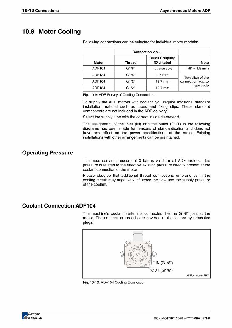
10-10 Connections Asynchronous Motors ADF
DOK-MOTOR*-ADF1x4*****-PR01-EN-P
10.8 Motor Cooling
Following connections can be selected for individual motor models:
Connection via...
Motor ThreadQuick Coupling
[Ø di tube] Note
ADF104 G1/8" not available 1/8" = 1/8 inch
ADF134 G1/4" 9.6 mm
ADF164 G1/2" 12.7 mm
ADF184 G1/2" 12.7 mm
Selection of theconnection acc. to
type code
Fig. 10-9: ADF Survey of Cooling Connections
To supply the ADF motors with coolant, you require additional standardinstallation material such as tubes and fixing clips. These standardcomponents are not included in the ADF delivery.
Select the supply tube with the correct inside diameter di.
The assignment of the inlet (IN) and the outlet (OUT) in the followingdiagrams has been made for reasons of standardisation and does nothave any effect on the power specifications of the motor. Existinginstallations with other arrangements can be maintained.
Operating PressureThe max. coolant pressure of 3 bar is valid for all ADF motors. Thispressure is related to the effective existing pressure directly present at thecoolant connection of the motor.
Please observe that additional thread connections or branches in thecooling circuit may negatively influence the flow and the supply pressureof the coolant.
Coolant Connection ADF104The machine's coolant system is connected the the G1/8" joint at themotor. The connection threads are covered at the factory by protectiveplugs.
IN (G1/8")
OUT (G1/8")ADFconnect8.FH7
Fig. 10-10: ADF104 Cooling Connection
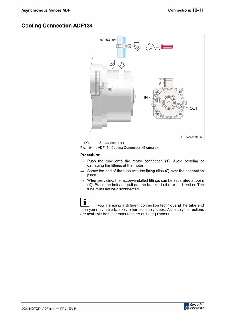
Asynchronous Motors ADF Connections 10-11
DOK-MOTOR*-ADF1x4*****-PR01-EN-P
Cooling Connection ADF134
2
1
OUT
IN
di = 9,6 mm
X
ADFconnect9.FH7
(X): Separation pointFig. 10-11: ADF134 Cooling Connection (Example)
Procedure:
⇒ Push the tube onto the motor connection (1). Avoid bending ordamaging the fittings at the motor .
⇒ Screw the end of the tube with the fixing clips (2) over the connectionpiece.
⇒ When servicing, the factory-installed fittings can be separated at point(X). Press the bolt and pull out the bracket in the axial direction. Thetube must not be disconnected.
If you are using a different connection technique at the tube endthen you may have to apply other assembly steps. Assembly instructionsare available from the manufacturer of the equipment.
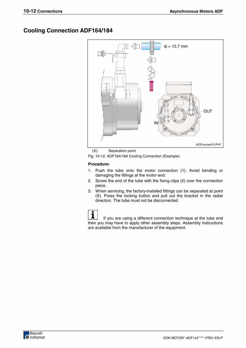
10-12 Connections Asynchronous Motors ADF
DOK-MOTOR*-ADF1x4*****-PR01-EN-P
Cooling Connection ADF164/184
X
di = 12,7 mm
2
1
OUT
IN
ADFconnect10.FH7
(X): Separation pointFig. 10-12: ADF164/184 Cooling Connection (Example)
Procedure:
1. Push the tube onto the motor connection (1). Avoid bending ordamaging the fittings at the motor end.
2. Screw the end of the tube with the fixing clips (2) over the connectionpiece.
3. When servicing, the factory-installed fittings can be separated at point(X). Press the locking button and pull out the bracket in the radialdirection. The tube must not be disconnected.
If you are using a different connection technique at the tube endthen you may have to apply other assembly steps. Assembly instructionsare available from the manufacturer of the equipment.
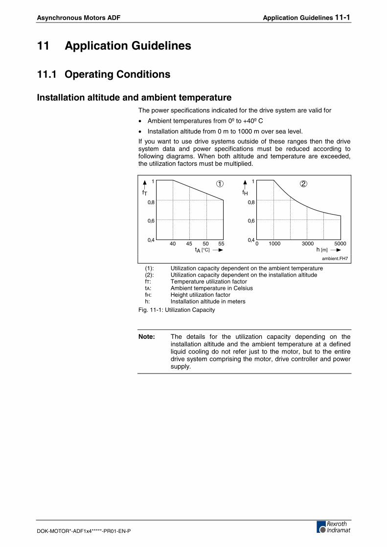
Asynchronous Motors ADF Application Guidelines 11-1
DOK-MOTOR*-ADF1x4*****-PR01-EN-P
11 Application Guidelines
11.1 Operating Conditions
Installation altitude and ambient temperatureThe power specifications indicated for the drive system are valid for
• Ambient temperatures from 0º to +40º C
• Installation altitude from 0 m to 1000 m over sea level.
If you want to use drive systems outside of these ranges then the drivesystem data and power specifications must be reduced according tofollowing diagrams. When both altitude and temperature are exceeded,the utilization factors must be multiplied.
1 2fT
tA [°C]1000 3000 5000
0,6
0,8
1
40 45 50 55 0
fH
h [m]
0,4
0,6
0,8
1
0,4
ambient.FH7
(1): Utilization capacity dependent on the ambient temperature(2): Utilization capacity dependent on the installation altitudefT: Temperature utilization factortA: Ambient temperature in CelsiusfH: Height utilization factorh: Installation altitude in meters
Fig. 11-1: Utilization Capacity
Note: The details for the utilization capacity depending on theinstallation altitude and the ambient temperature at a definedliquid cooling do not refer just to the motor, but to the entiredrive system comprising the motor, drive controller and powersupply.
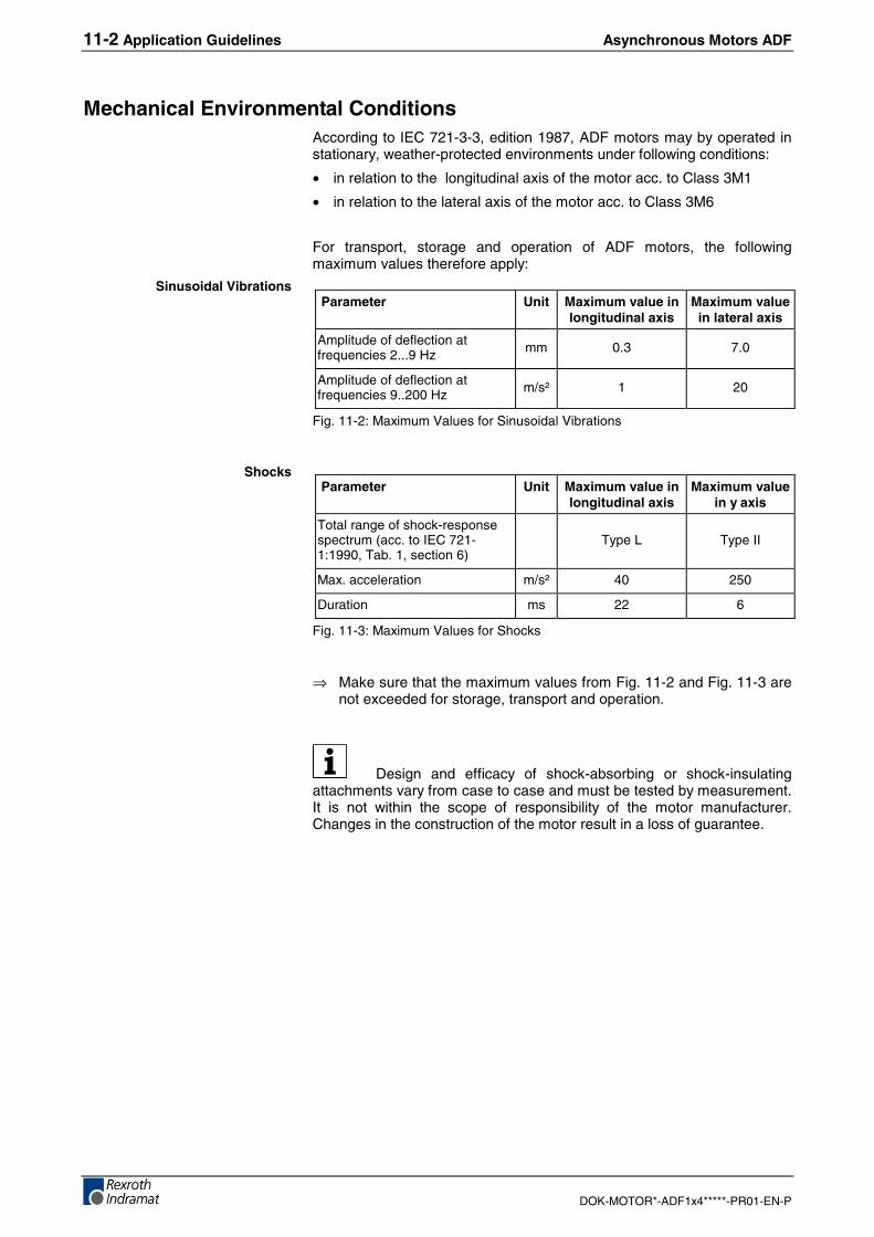
11-2 Application Guidelines Asynchronous Motors ADF
DOK-MOTOR*-ADF1x4*****-PR01-EN-P
Mechanical Environmental ConditionsAccording to IEC 721-3-3, edition 1987, ADF motors may by operated instationary, weather-protected environments under following conditions:
• in relation to the longitudinal axis of the motor acc. to Class 3M1
• in relation to the lateral axis of the motor acc. to Class 3M6
For transport, storage and operation of ADF motors, the followingmaximum values therefore apply:
Parameter Unit Maximum value inlongitudinal axis
Maximum valuein lateral axis
Amplitude of deflection atfrequencies 2...9 Hz mm 0.3 7.0
Amplitude of deflection atfrequencies 9..200 Hz m/s² 1 20
Fig. 11-2: Maximum Values for Sinusoidal Vibrations
Parameter Unit Maximum value inlongitudinal axis
Maximum valuein y axis
Total range of shock-responsespectrum (acc. to IEC 721-1:1990, Tab. 1, section 6)
Type L Type II
Max. acceleration m/s² 40 250
Duration ms 22 6
Fig. 11-3: Maximum Values for Shocks
⇒ Make sure that the maximum values from Fig. 11-2 and Fig. 11-3 arenot exceeded for storage, transport and operation.
Design and efficacy of shock-absorbing or shock-insulatingattachments vary from case to case and must be tested by measurement.It is not within the scope of responsibility of the motor manufacturer.Changes in the construction of the motor result in a loss of guarantee.
Sinusoidal Vibrations
Shocks
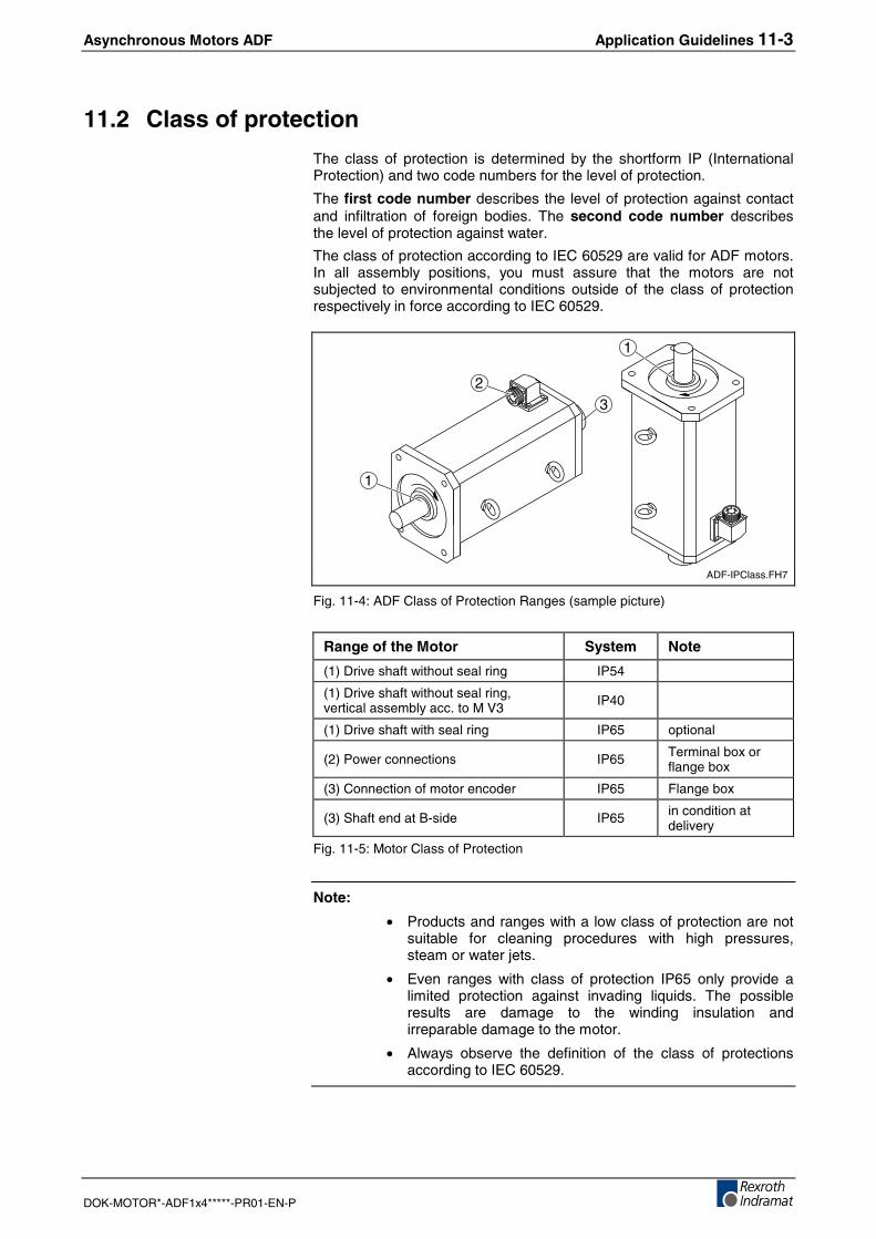
Asynchronous Motors ADF Application Guidelines 11-3
DOK-MOTOR*-ADF1x4*****-PR01-EN-P
11.2 Class of protection
The class of protection is determined by the shortform IP (InternationalProtection) and two code numbers for the level of protection.
The first code number describes the level of protection against contactand infiltration of foreign bodies. The second code number describesthe level of protection against water.
The class of protection according to IEC 60529 are valid for ADF motors.In all assembly positions, you must assure that the motors are notsubjected to environmental conditions outside of the class of protectionrespectively in force according to IEC 60529.
3
1
1
2
ADF-IPClass.FH7
Fig. 11-4: ADF Class of Protection Ranges (sample picture)
Range of the Motor System Note
(1) Drive shaft without seal ring IP54
(1) Drive shaft without seal ring,vertical assembly acc. to M V3 IP40
(1) Drive shaft with seal ring IP65 optional
(2) Power connections IP65 Terminal box orflange box
(3) Connection of motor encoder IP65 Flange box
(3) Shaft end at B-side IP65 in condition atdelivery
Fig. 11-5: Motor Class of Protection
Note:
• Products and ranges with a low class of protection are notsuitable for cleaning procedures with high pressures,steam or water jets.
• Even ranges with class of protection IP65 only provide alimited protection against invading liquids. The possibleresults are damage to the winding insulation andirreparable damage to the motor.
• Always observe the definition of the class of protectionsaccording to IEC 60529.
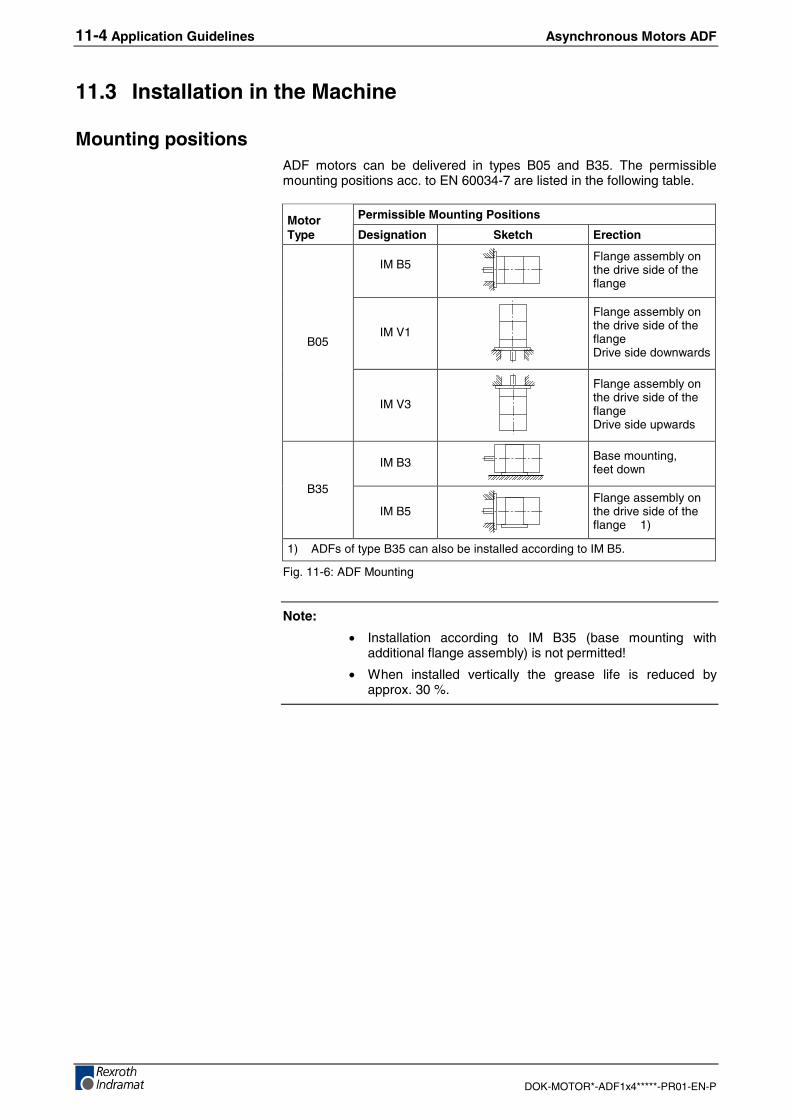
11-4 Application Guidelines Asynchronous Motors ADF
DOK-MOTOR*-ADF1x4*****-PR01-EN-P
11.3 Installation in the Machine
Mounting positionsADF motors can be delivered in types B05 and B35. The permissiblemounting positions acc. to EN 60034-7 are listed in the following table.
Permissible Mounting PositionsMotorType Designation Sketch Erection
IM B5Flange assembly onthe drive side of theflange
IM V1
Flange assembly onthe drive side of theflangeDrive side downwards
B05
IM V3
Flange assembly onthe drive side of theflangeDrive side upwards
IM B3 Base mounting,feet down
B35
IM B5Flange assembly onthe drive side of theflange 1)
1) ADFs of type B35 can also be installed according to IM B5.
Fig. 11-6: ADF Mounting
Note:
• Installation according to IM B35 (base mounting withadditional flange assembly) is not permitted!
• When installed vertically the grease life is reduced byapprox. 30 %.
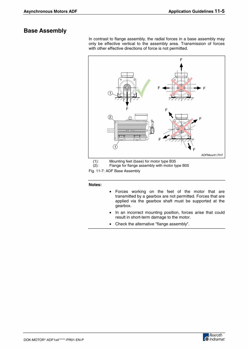
Asynchronous Motors ADF Application Guidelines 11-5
DOK-MOTOR*-ADF1x4*****-PR01-EN-P
Base AssemblyIn contrast to flange assembly, the radial forces in a base assembly mayonly be effective vertical to the assembly area. Transmission of forceswith other effective directions of force is not permitted.
F
FF
F
F
F
F
F
1
2
1
ADFMount1.FH7
(1): Mounting feet (base) for motor type B35(2): Flange for flange assembly with motor type B05
Fig. 11-7: ADF Base Assembly
Notes:
• Forces working on the feet of the motor that aretransmitted by a gearbox are not permitted. Forces that areapplied via the gearbox shaft must be supported at thegearbox.
• In an incorrect mounting position, forces arise that couldresult in short-term damage to the motor.
• Check the alternative "flange assembly".
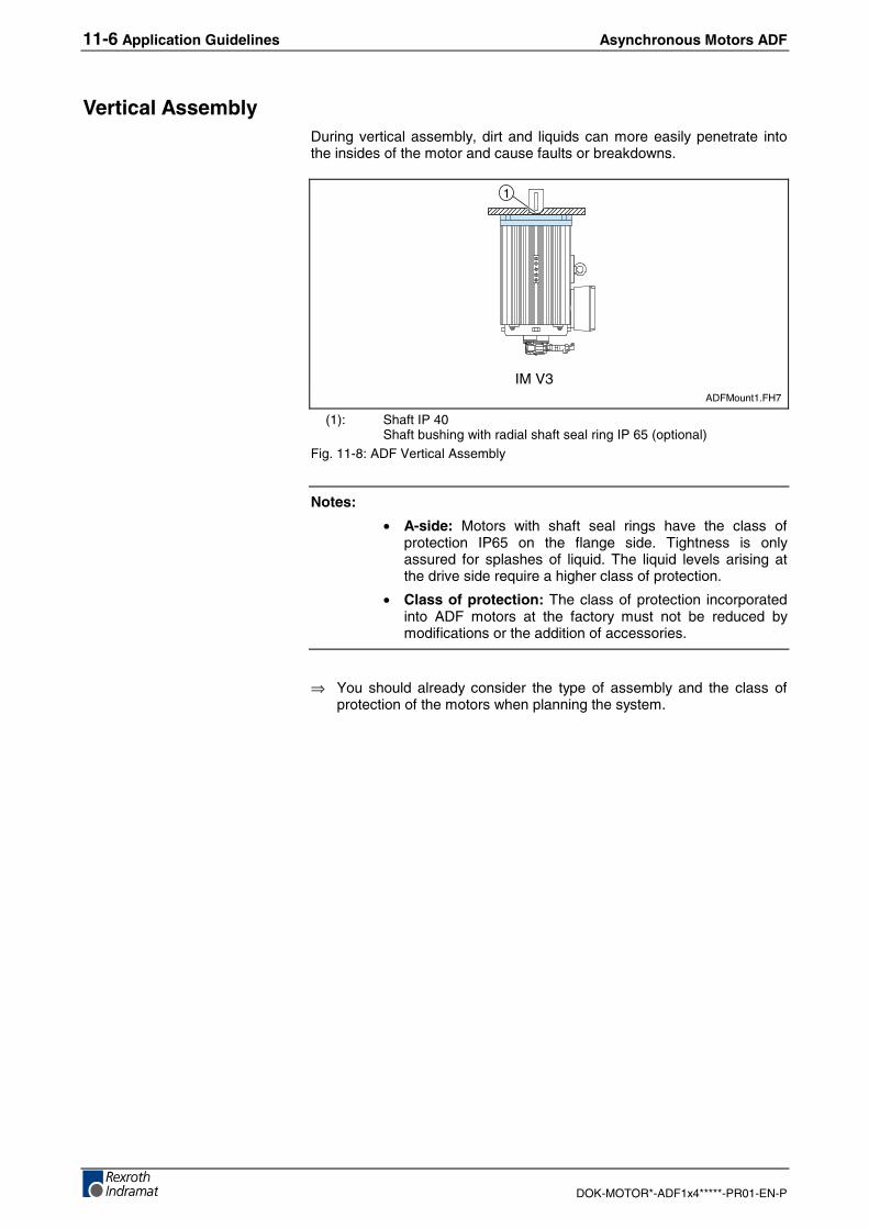
11-6 Application Guidelines Asynchronous Motors ADF
DOK-MOTOR*-ADF1x4*****-PR01-EN-P
Vertical AssemblyDuring vertical assembly, dirt and liquids can more easily penetrate intothe insides of the motor and cause faults or breakdowns.
IM V3
1
ADFMount1.FH7
(1): Shaft IP 40Shaft bushing with radial shaft seal ring IP 65 (optional)
Fig. 11-8: ADF Vertical Assembly
Notes:
• A-side: Motors with shaft seal rings have the class ofprotection IP65 on the flange side. Tightness is onlyassured for splashes of liquid. The liquid levels arising atthe drive side require a higher class of protection.
• Class of protection: The class of protection incorporatedinto ADF motors at the factory must not be reduced bymodifications or the addition of accessories.
⇒ You should already consider the type of assembly and the class ofprotection of the motors when planning the system.
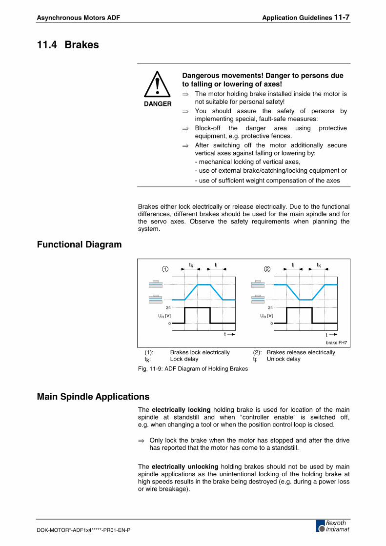
Asynchronous Motors ADF Application Guidelines 11-7
DOK-MOTOR*-ADF1x4*****-PR01-EN-P
11.4 Brakes
DANGER
Dangerous movements! Danger to persons dueto falling or lowering of axes!⇒ The motor holding brake installed inside the motor is
not suitable for personal safety!⇒ You should assure the safety of persons by
implementing special, fault-safe measures:⇒ Block-off the danger area using protective
equipment, e.g. protective fences.⇒ After switching off the motor additionally secure
vertical axes against falling or lowering by:- mechanical locking of vertical axes,- use of external brake/catching/locking equipment or
- use of sufficient weight compensation of the axes
Brakes either lock electrically or release electrically. Due to the functionaldifferences, different brakes should be used for the main spindle and forthe servo axes. Observe the safety requirements when planning thesystem.
Functional Diagram
t
1 2
Un [V]
0
24
Un [V]
0
24
tktltk tl
t
brake.FH7
(1): Brakes lock electrically (2): Brakes release electricallytk: Lock delay tl: Unlock delay
Fig. 11-9: ADF Diagram of Holding Brakes
Main Spindle ApplicationsThe electrically locking holding brake is used for location of the mainspindle at standstill and when "controller enable" is switched off,e.g. when changing a tool or when the position control loop is closed.
⇒ Only lock the brake when the motor has stopped and after the drivehas reported that the motor has come to a standstill.
The electrically unlocking holding brakes should not be used by mainspindle applications as the unintentional locking of the holding brake athigh speeds results in the brake being destroyed (e.g. during a power lossor wire breakage).
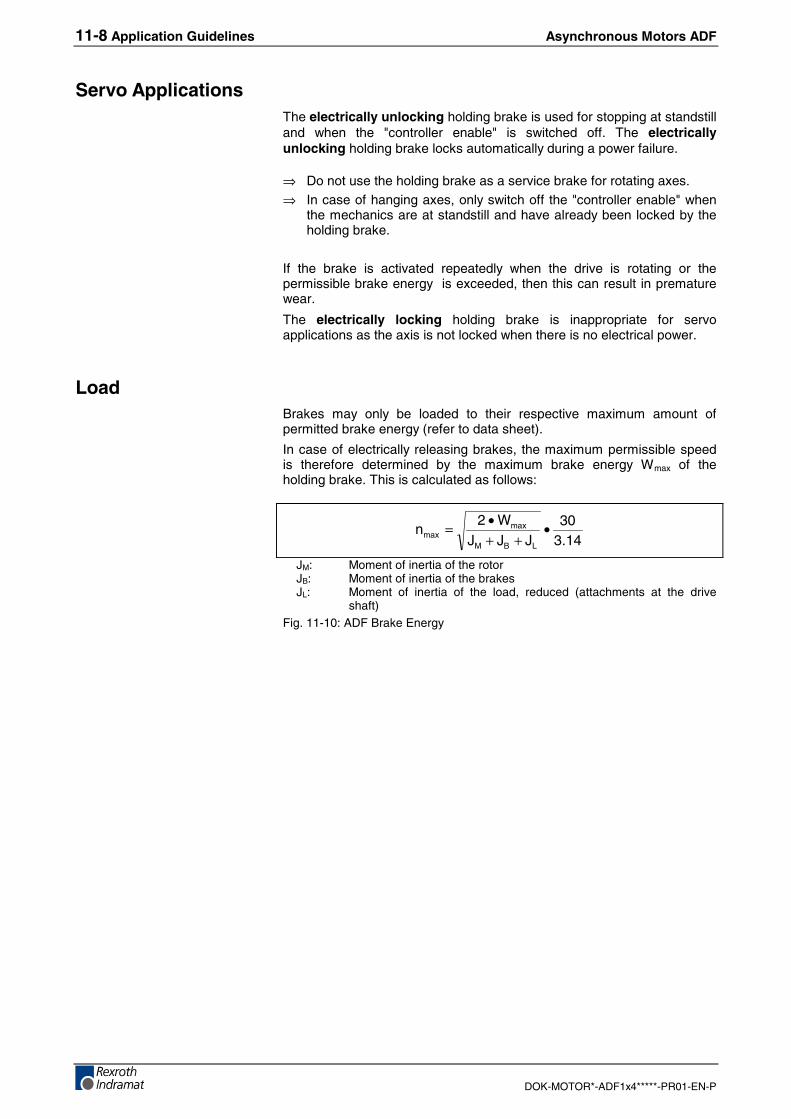
11-8 Application Guidelines Asynchronous Motors ADF
DOK-MOTOR*-ADF1x4*****-PR01-EN-P
Servo ApplicationsThe electrically unlocking holding brake is used for stopping at standstilland when the "controller enable" is switched off. The electricallyunlocking holding brake locks automatically during a power failure.
⇒ Do not use the holding brake as a service brake for rotating axes.⇒ In case of hanging axes, only switch off the "controller enable" when
the mechanics are at standstill and have already been locked by theholding brake.
If the brake is activated repeatedly when the drive is rotating or thepermissible brake energy is exceeded, then this can result in prematurewear.
The electrically locking holding brake is inappropriate for servoapplications as the axis is not locked when there is no electrical power.
LoadBrakes may only be loaded to their respective maximum amount ofpermitted brake energy (refer to data sheet).
In case of electrically releasing brakes, the maximum permissible speedis therefore determined by the maximum brake energy Wmax of theholding brake. This is calculated as follows:
14.330
JJJW2
nLBM
maxmax •
++•=
JM: Moment of inertia of the rotorJB: Moment of inertia of the brakesJL: Moment of inertia of the load, reduced (attachments at the drive
shaft)Fig. 11-10: ADF Brake Energy
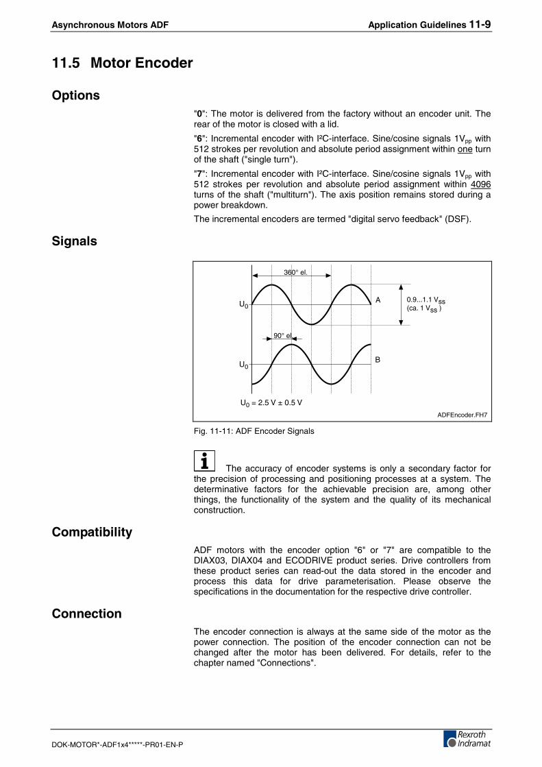
Asynchronous Motors ADF Application Guidelines 11-9
DOK-MOTOR*-ADF1x4*****-PR01-EN-P
11.5 Motor Encoder
Options"0": The motor is delivered from the factory without an encoder unit. Therear of the motor is closed with a lid.
"6": Incremental encoder with I²C-interface. Sine/cosine signals 1Vpp with512 strokes per revolution and absolute period assignment within one turnof the shaft ("single turn").
"7": Incremental encoder with I²C-interface. Sine/cosine signals 1Vpp with512 strokes per revolution and absolute period assignment within 4096turns of the shaft ("multiturn"). The axis position remains stored during apower breakdown.
The incremental encoders are termed "digital servo feedback" (DSF).
Signals
U0
U0
360° el.
90° el.
A
B
U0 = 2.5 V ± 0.5 V
0.9...1.1 Vss(ca. 1 Vss )
ADFEncoder.FH7
Fig. 11-11: ADF Encoder Signals
The accuracy of encoder systems is only a secondary factor forthe precision of processing and positioning processes at a system. Thedeterminative factors for the achievable precision are, among otherthings, the functionality of the system and the quality of its mechanicalconstruction.
CompatibilityADF motors with the encoder option "6" or "7" are compatible to theDIAX03, DIAX04 and ECODRIVE product series. Drive controllers fromthese product series can read-out the data stored in the encoder andprocess this data for drive parameterisation. Please observe thespecifications in the documentation for the respective drive controller.
ConnectionThe encoder connection is always at the same side of the motor as thepower connection. The position of the encoder connection can not bechanged after the motor has been delivered. For details, refer to thechapter named "Connections".
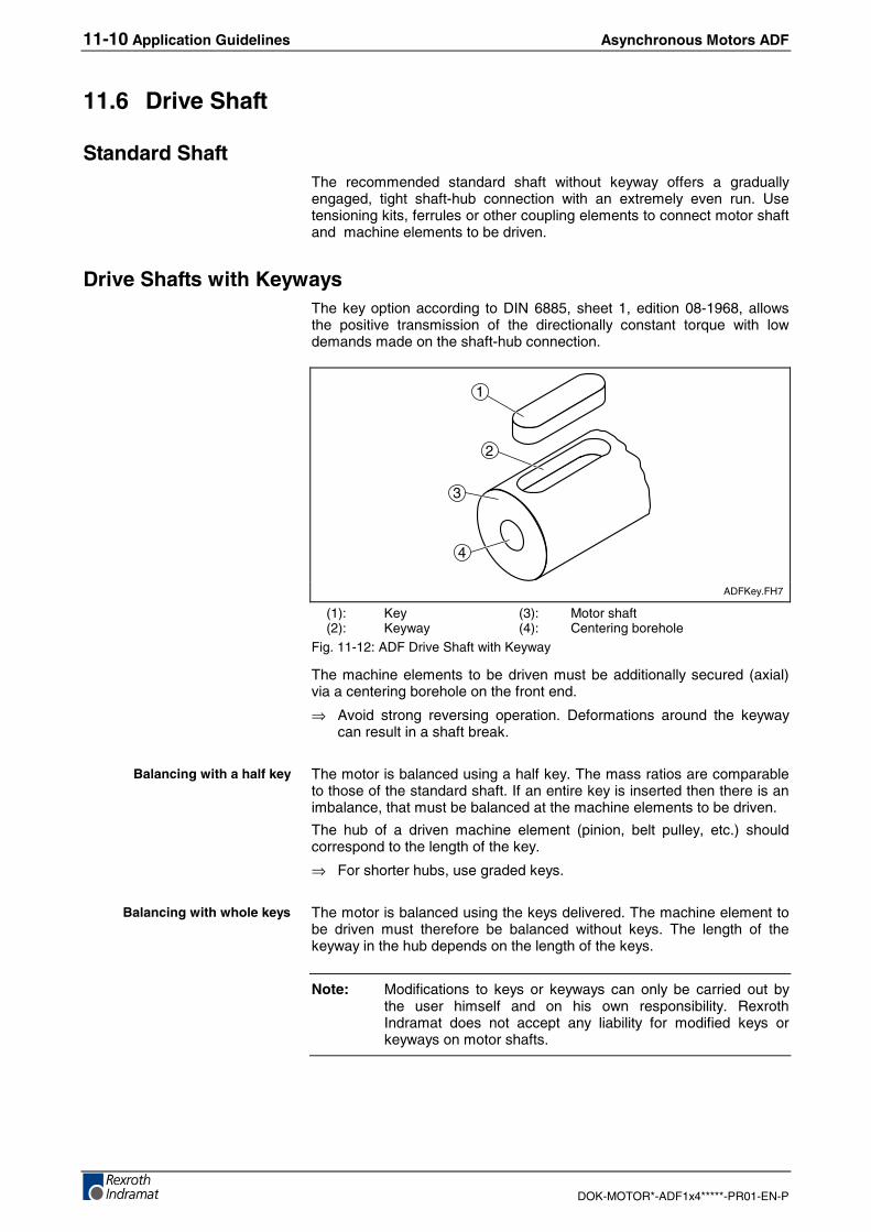
11-10 Application Guidelines Asynchronous Motors ADF
DOK-MOTOR*-ADF1x4*****-PR01-EN-P
11.6 Drive Shaft
Standard ShaftThe recommended standard shaft without keyway offers a graduallyengaged, tight shaft-hub connection with an extremely even run. Usetensioning kits, ferrules or other coupling elements to connect motor shaftand machine elements to be driven.
Drive Shafts with KeywaysThe key option according to DIN 6885, sheet 1, edition 08-1968, allowsthe positive transmission of the directionally constant torque with lowdemands made on the shaft-hub connection.
1
2
3
4
ADFKey.FH7
(1): Key (3): Motor shaft(2): Keyway (4): Centering borehole
Fig. 11-12: ADF Drive Shaft with Keyway
The machine elements to be driven must be additionally secured (axial)via a centering borehole on the front end.
⇒ Avoid strong reversing operation. Deformations around the keywaycan result in a shaft break.
The motor is balanced using a half key. The mass ratios are comparableto those of the standard shaft. If an entire key is inserted then there is animbalance, that must be balanced at the machine elements to be driven.
The hub of a driven machine element (pinion, belt pulley, etc.) shouldcorrespond to the length of the key.
⇒ For shorter hubs, use graded keys.
The motor is balanced using the keys delivered. The machine element tobe driven must therefore be balanced without keys. The length of thekeyway in the hub depends on the length of the keys.
Note: Modifications to keys or keyways can only be carried out bythe user himself and on his own responsibility. RexrothIndramat does not accept any liability for modified keys orkeyways on motor shafts.
Balancing with a half key
Balancing with whole keys
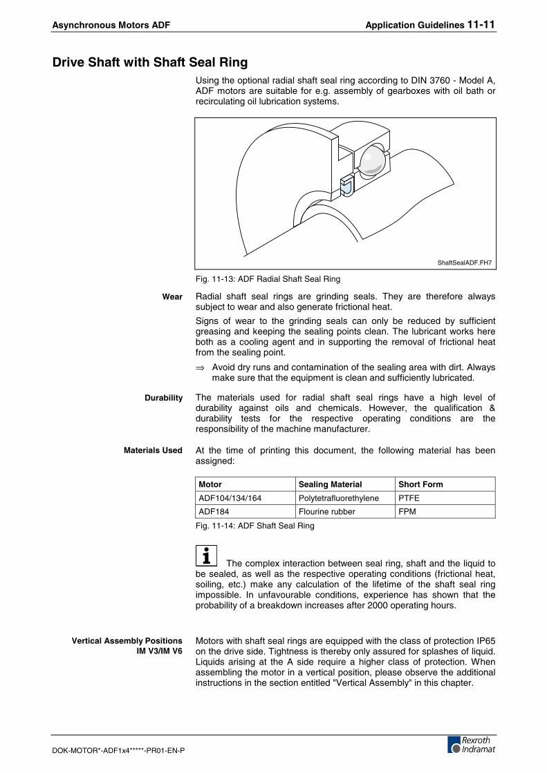
Asynchronous Motors ADF Application Guidelines 11-11
DOK-MOTOR*-ADF1x4*****-PR01-EN-P
Drive Shaft with Shaft Seal RingUsing the optional radial shaft seal ring according to DIN 3760 - Model A,ADF motors are suitable for e.g. assembly of gearboxes with oil bath orrecirculating oil lubrication systems.
ShaftSealADF.FH7
Fig. 11-13: ADF Radial Shaft Seal Ring
Radial shaft seal rings are grinding seals. They are therefore alwayssubject to wear and also generate frictional heat.
Signs of wear to the grinding seals can only be reduced by sufficientgreasing and keeping the sealing points clean. The lubricant works hereboth as a cooling agent and in supporting the removal of frictional heatfrom the sealing point.
⇒ Avoid dry runs and contamination of the sealing area with dirt. Alwaysmake sure that the equipment is clean and sufficiently lubricated.
The materials used for radial shaft seal rings have a high level ofdurability against oils and chemicals. However, the qualification &durability tests for the respective operating conditions are theresponsibility of the machine manufacturer.
At the time of printing this document, the following material has beenassigned:
Motor Sealing Material Short Form
ADF104/134/164 Polytetrafluorethylene PTFE
ADF184 Flourine rubber FPM
Fig. 11-14: ADF Shaft Seal Ring
The complex interaction between seal ring, shaft and the liquid tobe sealed, as well as the respective operating conditions (frictional heat,soiling, etc.) make any calculation of the lifetime of the shaft seal ringimpossible. In unfavourable conditions, experience has shown that theprobability of a breakdown increases after 2000 operating hours.
Motors with shaft seal rings are equipped with the class of protection IP65on the drive side. Tightness is thereby only assured for splashes of liquid.Liquids arising at the A side require a higher class of protection. Whenassembling the motor in a vertical position, please observe the additionalinstructions in the section entitled "Vertical Assembly" in this chapter.
Wear
Durability
Materials Used
Vertical Assembly PositionsIM V3/IM V6
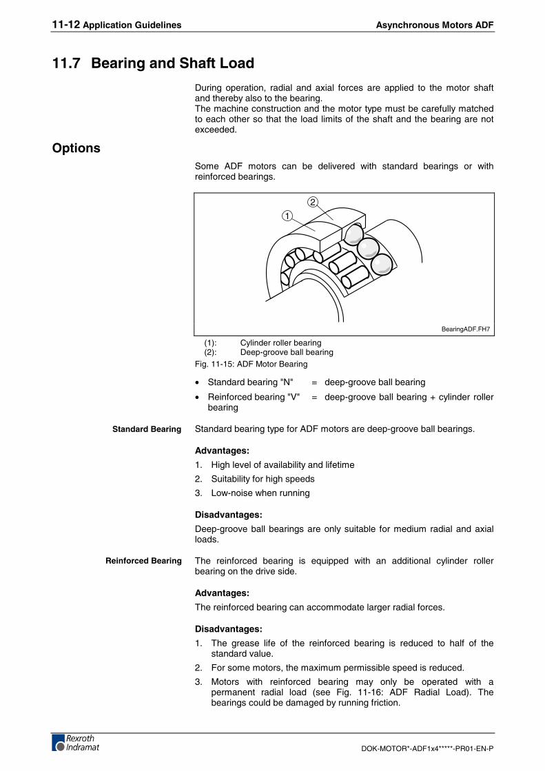
11-12 Application Guidelines Asynchronous Motors ADF
DOK-MOTOR*-ADF1x4*****-PR01-EN-P
11.7 Bearing and Shaft Load
During operation, radial and axial forces are applied to the motor shaftand thereby also to the bearing.The machine construction and the motor type must be carefully matchedto each other so that the load limits of the shaft and the bearing are notexceeded.
OptionsSome ADF motors can be delivered with standard bearings or withreinforced bearings.
1
2
BearingADF.FH7
(1): Cylinder roller bearing(2): Deep-groove ball bearing
Fig. 11-15: ADF Motor Bearing
• Standard bearing "N" = deep-groove ball bearing
• Reinforced bearing "V" = deep-groove ball bearing + cylinder rollerbearing
Standard bearing type for ADF motors are deep-groove ball bearings.
Advantages:
1. High level of availability and lifetime
2. Suitability for high speeds
3. Low-noise when running
Disadvantages:
Deep-groove ball bearings are only suitable for medium radial and axialloads.
The reinforced bearing is equipped with an additional cylinder rollerbearing on the drive side.
Advantages:
The reinforced bearing can accommodate larger radial forces.
Disadvantages:
1. The grease life of the reinforced bearing is reduced to half of thestandard value.
2. For some motors, the maximum permissible speed is reduced.
3. Motors with reinforced bearing may only be operated with apermanent radial load (see Fig. 11-16: ADF Radial Load). Thebearings could be damaged by running friction.
Standard Bearing
Reinforced Bearing
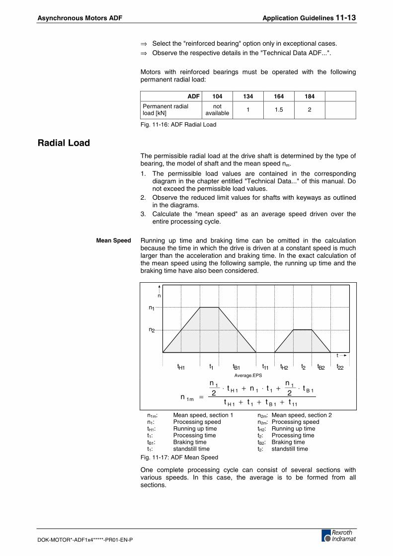
Asynchronous Motors ADF Application Guidelines 11-13
DOK-MOTOR*-ADF1x4*****-PR01-EN-P
⇒ Select the "reinforced bearing" option only in exceptional cases.⇒ Observe the respective details in the "Technical Data ADF...".
Motors with reinforced bearings must be operated with the followingpermanent radial load:
ADF 104 134 164 184
Permanent radialload [kN]
notavailable 1 1.5 2
Fig. 11-16: ADF Radial Load
Radial LoadThe permissible radial load at the drive shaft is determined by the type ofbearing, the model of shaft and the mean speed nm.
1. The permissible load values are contained in the correspondingdiagram in the chapter entitled "Technical Data..." of this manual. Donot exceed the permissible load values.
2. Observe the reduced limit values for shafts with keyways as outlinedin the diagrams.
3. Calculate the "mean speed" as an average speed driven over theentire processing cycle.
Running up time and braking time can be omitted in the calculationbecause the time in which the drive is driven at a constant speed is muchlarger than the acceleration and braking time. In the exact calculation ofthe mean speed using the following sample, the running up time and thebraking time have also been considered.
n
t
tH1 t1 tB1 t11 tH2 t2 tB2 t22
n1
n2
Average.EPS
111B11H
1B1
111H1
m1 tttt
t2
ntnt
2n
n+++
⋅+⋅+⋅=
n1m: Mean speed, section 1 n2m: Mean speed, section 2n1: Processing speed n2m: Processing speedtH1: Running up time tH2: Running up timet1: Processing time t2: Processing timetB1: Braking time tB2: Braking timet1: standstill time t2: standstill time
Fig. 11-17: ADF Mean Speed
One complete processing cycle can consist of several sections withvarious speeds. In this case, the average is to be formed from allsections.
Mean Speed
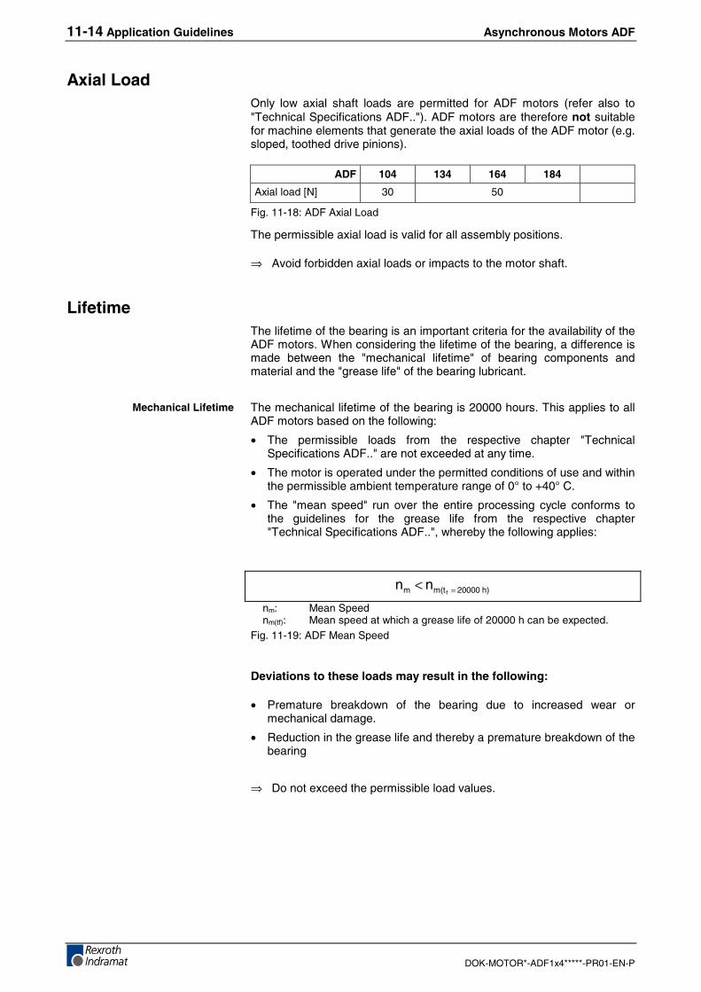
11-14 Application Guidelines Asynchronous Motors ADF
DOK-MOTOR*-ADF1x4*****-PR01-EN-P
Axial LoadOnly low axial shaft loads are permitted for ADF motors (refer also to"Technical Specifications ADF.."). ADF motors are therefore not suitablefor machine elements that generate the axial loads of the ADF motor (e.g.sloped, toothed drive pinions).
ADF 104 134 164 184
Axial load [N] 30 50
Fig. 11-18: ADF Axial Load
The permissible axial load is valid for all assembly positions.
⇒ Avoid forbidden axial loads or impacts to the motor shaft.
LifetimeThe lifetime of the bearing is an important criteria for the availability of theADF motors. When considering the lifetime of the bearing, a difference ismade between the "mechanical lifetime" of bearing components andmaterial and the "grease life" of the bearing lubricant.
The mechanical lifetime of the bearing is 20000 hours. This applies to allADF motors based on the following:
• The permissible loads from the respective chapter "TechnicalSpecifications ADF.." are not exceeded at any time.
• The motor is operated under the permitted conditions of use and withinthe permissible ambient temperature range of 0° to +40° C.
• The "mean speed" run over the entire processing cycle conforms tothe guidelines for the grease life from the respective chapter"Technical Specifications ADF..", whereby the following applies:
h)20000m(tm fnn =<
nm: Mean Speednm(tf): Mean speed at which a grease life of 20000 h can be expected.
Fig. 11-19: ADF Mean Speed
Deviations to these loads may result in the following:
• Premature breakdown of the bearing due to increased wear ormechanical damage.
• Reduction in the grease life and thereby a premature breakdown of thebearing
⇒ Do not exceed the permissible load values.
Mechanical Lifetime
Asynchronous Motors ADF Application Guidelines 11-15
DOK-MOTOR*-ADF1x4*****-PR01-EN-P
The deep-groove ball bearing and the cylinder roller bearing in ADFmotors are greased for life . The grease life to be expected is shown in adiagram in the chapter entitled "Technical Data ADF.." and should bedetermined for every use.
In the diagram, various guidelines are contained for the "standardbearing" and the "reinforced bearing". The guidelines for the grease lifefor ADF motors is based on the following:
• The permissible loads from the respective chapter "Technical DataADF.." are not exceeded at any time.
• The higher the "mean speed" that is driven over the entire processingcycle is, the smaller will be the available grease life.
When the available grease life has expired, the probability that thebearing and the motor break down, will increase. Particularly in caseswhere the motor has a reinforced bearing, this can lead to a much lowermotor operating time.
If the availability of the motor is limited by a short grease life then themotor availability can be extended in some special cases by using thestandard bearing instead of the reinforced bearing, whereby the greaselife increases. However, the higher load of the standard bearing reducesthe available mechanical lifetime to under 20000 operating hours.
This case requires that the lifetime of the bearing be recalculated byREXROTH INDRAMAT. Please contact one of our branches and provideus with details of usage and all relevant application data (load cycle, axialand radial loads, speeds).
Calculation and design of the bearing is based on the standardDIN ISO 281.
Grease Life
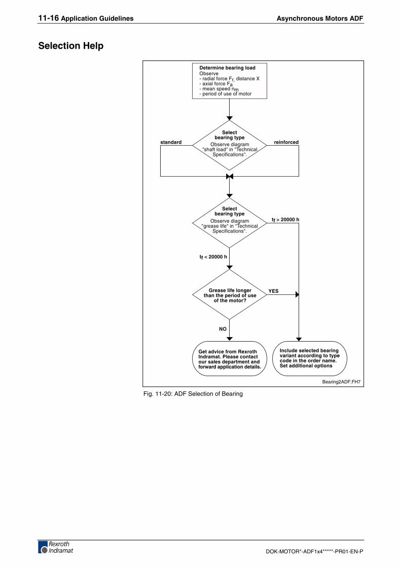
11-16 Application Guidelines Asynchronous Motors ADF
DOK-MOTOR*-ADF1x4*****-PR01-EN-P
Selection Help
/�������������������C3�����*������%���2��(�-�������2��G*��#��%���2��(�*�������$������*�$�������.��������
0�������������!�
C3�������������8������%��8����8,�2���2�%
�$�2���2�����8�
0�������������!�
C3�������������8�������%���8����8,�2���2�%
�$�2���2�����8�
������ ���� ����
5��� ���� ��������������!����� �� �
������6
�7��....��
�8��....��
940
2$
5��������� ���:�;��<������������ ��������� ��� ���!��������� �"�����!!������������ �
<������� ��������������������������������!���������������������0�����������!��
Bearing2ADF.FH7
Fig. 11-20: ADF Selection of Bearing
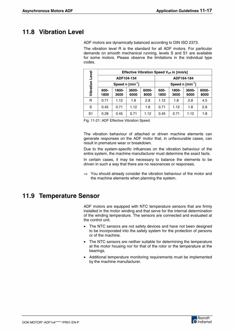
Asynchronous Motors ADF Application Guidelines 11-17
DOK-MOTOR*-ADF1x4*****-PR01-EN-P
11.8 Vibration Level
ADF motors are dynamically balanced according to DIN ISO 2373.
The vibration level R is the standard for all ADF motors. For particulardemands on smooth mechanical running, levels S and S1 are availablefor some motors. Please observe the limitations in the individual typecodes.
Effective Vibration Speed Veff in [mm/s]
ADF104-134 ADF164-184
Speed n [min-1] Speed n [min-1]
Vib
rati
on
Lev
el600-1800
1800-3600
3600-6000
6000-8000
600-1800
1800-3600
3600-6000
6000-8000
R 0.71 1.12 1.8 2.8 1.12 1.8 2.8 4.5
S 0.45 0.71 1.12 1.8 0.71 1.12 1.8 2.8
S1 0.28 0.45 0.71 1.12 0.45 0.71 1.12 1.8
Fig. 11-21: ADF Effective Vibration Speed
The vibration behaviour of attached or driven machine elements cangenerate responses on the ADF motor that, in unfavourable cases, canresult in premature wear or breakdown.
Due to the system-specific influences on the vibration behaviour of theentire system, the machine manufacturer must determine the exact facts.
In certain cases, it may be necessary to balance the elements to bedriven in such a way that there are no resonances or responses.
⇒ You should already consider the vibration behaviour of the motor andthe machine elements when planning the system.
11.9 Temperature Sensor
ADF motors are equipped with NTC temperature sensors that are firmlyinstalled in the motor winding and that serve for the internal determinationof the winding temperature. The sensors are connected and evaluated atthe control unit.
• The NTC sensors are not safety devices and have not been designedto be incorporated into the safety system for the protection of personsor of the machine.
• The NTC sensors are neither suitable for determining the temperatureat the motor housing nor for that of the rotor or the temperature at thebearings.
• Additional temperature monitoring requirements must be implementedby the machine manufacturer.
11-18 Application Guidelines Asynchronous Motors ADF
DOK-MOTOR*-ADF1x4*****-PR01-EN-P
11.10 Motor Cooling
The power loss PV of the motor is converted into heat and dissipated bythe cooling system. ADF motors may therefore only be operated when thesupply of coolant is assured. The cooling system must be designed by themachine manufacturer in such a way that all requirements on throughput,pressure, purity, temperature drops, etc. are observed in all operatingconditions.
CAUTION
Adverse effects or breakdown of motor,machine or cooling system!⇒ Always consider the motor specifications and the
explanations on the design of cooling systemscontained in the documentation "Liquid Cooling...,Dimensioning, Selection", Mat.No. 00265836.
⇒ When constructing and operating cooling systems,always observe the regulations of the manufacturer.
⇒ Do not use any cooling lubricant or cutting materialsfrom machine processes.
CoolantAll details and technical specifications refer to water as the coolant. Thisdata is no longer valid, and must be redetermined, if other coolants areused.
Cooling with running water from the public water supply is notrecommended. Calcareous water can cause deposits or corrosion anddamage both the motor and the cooling system.
For corrosion protection and for chemical stabilisation, an additive mustbe mixed in with the cooling water that is suitable for machine installationswith materials as shown in Fig. 11-23.
The use of aggressive coolants, additives or cooling lubricants can resultin irreparable damage to the motors.
⇒ Use systems with closed circuits and fine filters = 100 µm.⇒ When selecting the coolant, observe the environmental regulations
and the regulations on disposal.
Watery solutions assure reliable corrosion protection without anysignificant changes to the physical characteristics of the water. Therecommended additives do not contain any materials that are a danger tothe water.
Corrosion protection oils for cooling water circuits contain emulgators thatare responsible for the fine distribution of the oil in water. The oilycomponents in the emulsion protect the metal surfaces of the coolantchannel from corrosion and cavitation. An oil content of 0.5 to 2 Vol.-%has proven reliable.
If, in addition to corrosion protection, the corrosion oil is also to lubricatethe coolant pump then an oil content of approx. 5 Vol.-% is required.
⇒ Observe the regulations of the manufacturer of the equipment!
Watery Solution
Emulsion with CorrosionProtection
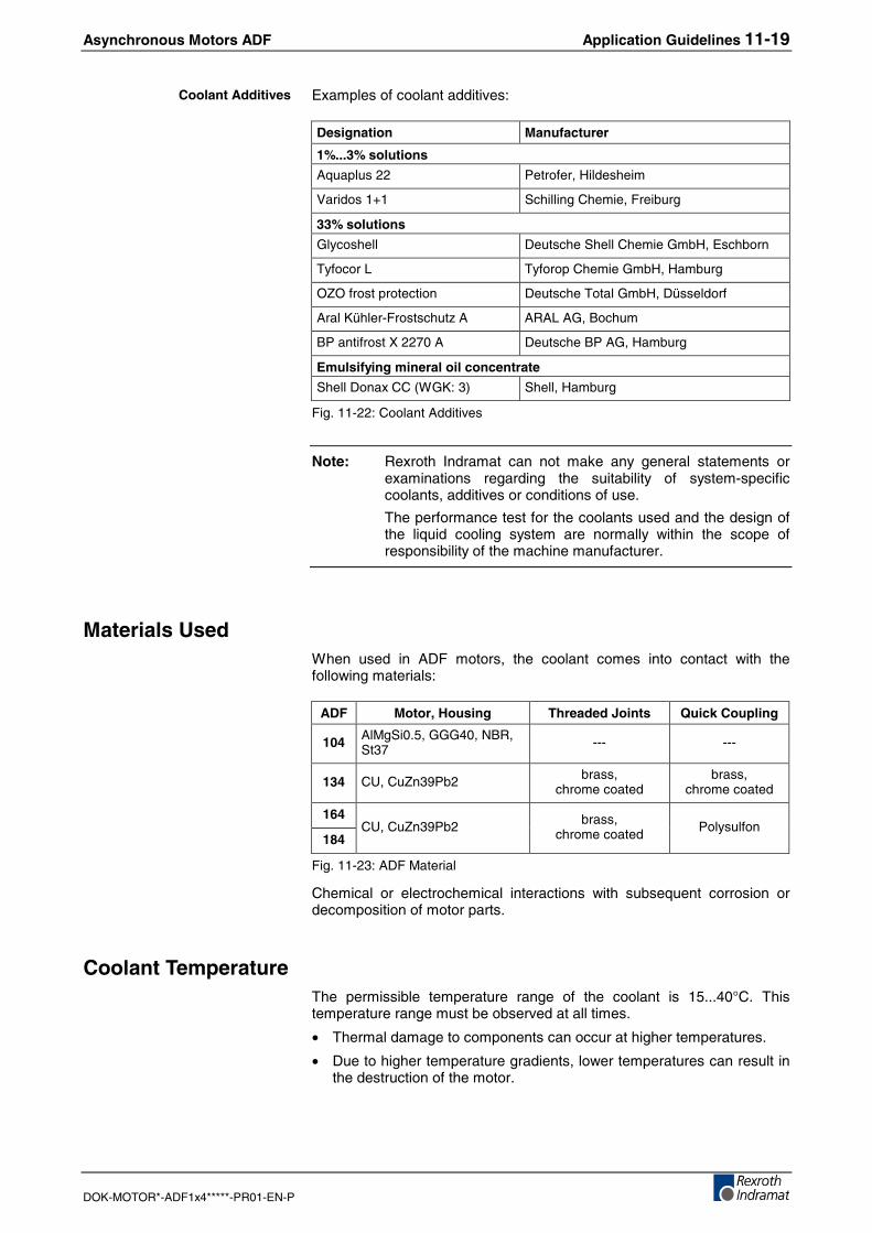
Asynchronous Motors ADF Application Guidelines 11-19
DOK-MOTOR*-ADF1x4*****-PR01-EN-P
Examples of coolant additives:
Designation Manufacturer
1%...3% solutions
Aquaplus 22 Petrofer, Hildesheim
Varidos 1+1 Schilling Chemie, Freiburg
33% solutions
Glycoshell Deutsche Shell Chemie GmbH, Eschborn
Tyfocor L Tyforop Chemie GmbH, Hamburg
OZO frost protection Deutsche Total GmbH, Düsseldorf
Aral Kühler-Frostschutz A ARAL AG, Bochum
BP antifrost X 2270 A Deutsche BP AG, Hamburg
Emulsifying mineral oil concentrate
Shell Donax CC (WGK: 3) Shell, Hamburg
Fig. 11-22: Coolant Additives
Note: Rexroth Indramat can not make any general statements orexaminations regarding the suitability of system-specificcoolants, additives or conditions of use.
The performance test for the coolants used and the design ofthe liquid cooling system are normally within the scope ofresponsibility of the machine manufacturer.
Materials UsedWhen used in ADF motors, the coolant comes into contact with thefollowing materials:
ADF Motor, Housing Threaded Joints Quick Coupling
104 AlMgSi0.5, GGG40, NBR,St37 --- ---
134 CU, CuZn39Pb2 brass,chrome coated
brass,chrome coated
164
184CU, CuZn39Pb2 brass,
chrome coated Polysulfon
Fig. 11-23: ADF Material
Chemical or electrochemical interactions with subsequent corrosion ordecomposition of motor parts.
Coolant TemperatureThe permissible temperature range of the coolant is 15...40°C. Thistemperature range must be observed at all times.
• Thermal damage to components can occur at higher temperatures.
• Due to higher temperature gradients, lower temperatures can result inthe destruction of the motor.
Coolant Additives
11-20 Application Guidelines Asynchronous Motors ADF
DOK-MOTOR*-ADF1x4*****-PR01-EN-P
Asynchronous Motors ADF Handling and Transport 12-1
DOK-MOTOR*-ADF1x4*****-PR01-EN-P
12 Handling and Transport
12.1 Condition on Delivery
ADF motors are packed in wooden boxes or in cartons on delivery(ADF104). Packing units on pallets are secured by tension bands.
CAUTION
Injuries due to uncontrolled movements of thetension bands when unpacking!⇒ Keep a safe distance and cut the tension bands
carefully.
Motor shafts and plug connections are provided with sleeves at thefactory. Only remove the sleeves immediately before assembly.
Factory ChecksAdditionally to all quality inspections during manufacturing and testingADF motors are subjected to the following tests before delivery:
• High-voltage test acc. to EN 60034-1 (corresponds to VDE 0530-1).
• Insulation resistance acc. to EN 60204-1/1.92, Section 20.3.
• Ground wire connection acc. to EN 60204-1/1.92, Section 20.3.
• True running and geometric tolerances of shaft end and mountingflange acc. to DIN 42955.
• Vibration testing acc. to DIN 2373.
Checks made by the CustomerAs all ADF motors are subjected to a standardized test procedure, high-voltage testing is not required by the customer. Motors and componentscan be damaged by repeated high-voltage tests.
CAREFUL
Destruction of motor components caused byimproper high-voltage tests! Loss of guarantee!⇒ Avoid repeated high-voltage tests.
⇒ Observe the regulations contained in EN 60034-1(corresponds to VDE 0530-1)
Electrical Test
Mechanical Test
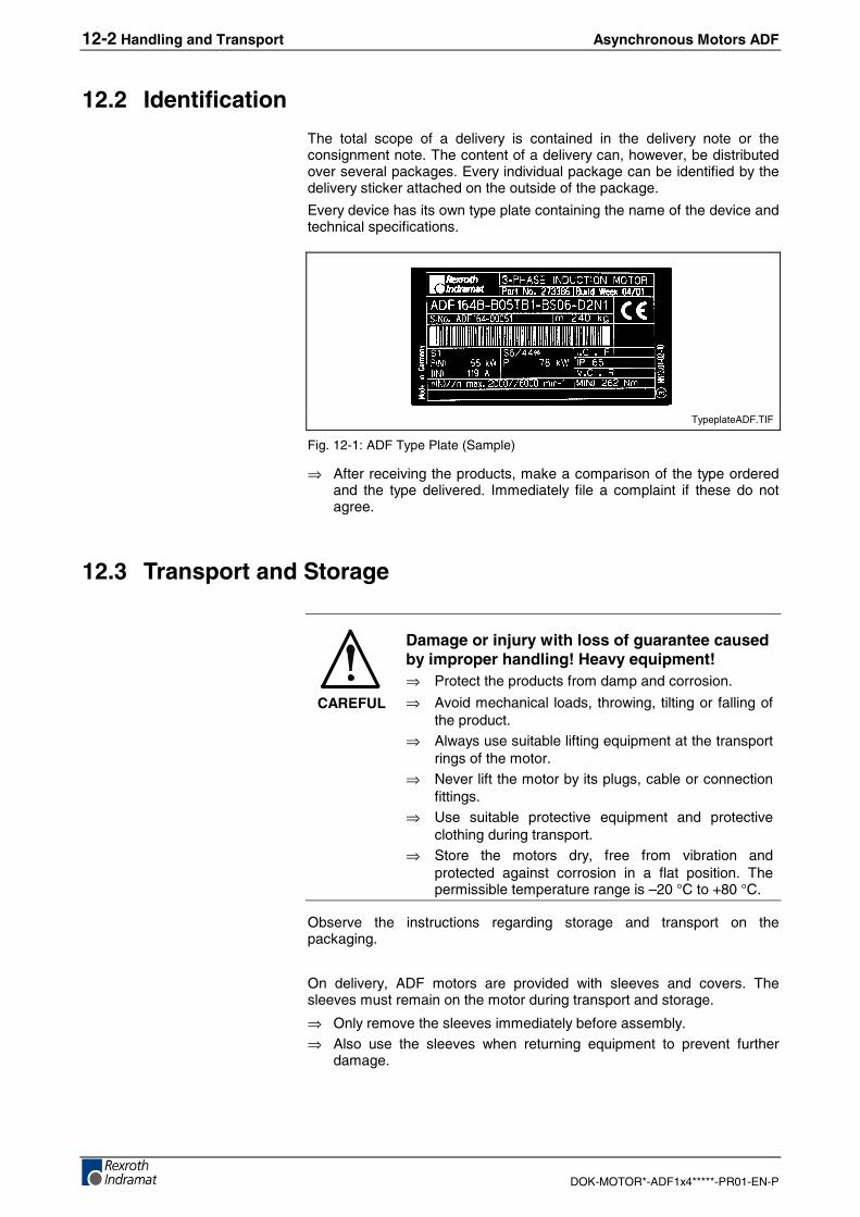
12-2 Handling and Transport Asynchronous Motors ADF
DOK-MOTOR*-ADF1x4*****-PR01-EN-P
12.2 Identification
The total scope of a delivery is contained in the delivery note or theconsignment note. The content of a delivery can, however, be distributedover several packages. Every individual package can be identified by thedelivery sticker attached on the outside of the package.
Every device has its own type plate containing the name of the device andtechnical specifications.
TypeplateADF.TIF
Fig. 12-1: ADF Type Plate (Sample)
⇒ After receiving the products, make a comparison of the type orderedand the type delivered. Immediately file a complaint if these do notagree.
12.3 Transport and Storage
CAREFUL
Damage or injury with loss of guarantee causedby improper handling! Heavy equipment!⇒ Protect the products from damp and corrosion.
⇒ Avoid mechanical loads, throwing, tilting or falling ofthe product.
⇒ Always use suitable lifting equipment at the transportrings of the motor.
⇒ Never lift the motor by its plugs, cable or connectionfittings.
⇒ Use suitable protective equipment and protectiveclothing during transport.
⇒ Store the motors dry, free from vibration andprotected against corrosion in a flat position. Thepermissible temperature range is –20 °C to +80 °C.
Observe the instructions regarding storage and transport on thepackaging.
On delivery, ADF motors are provided with sleeves and covers. Thesleeves must remain on the motor during transport and storage.
⇒ Only remove the sleeves immediately before assembly.⇒ Also use the sleeves when returning equipment to prevent further
damage.
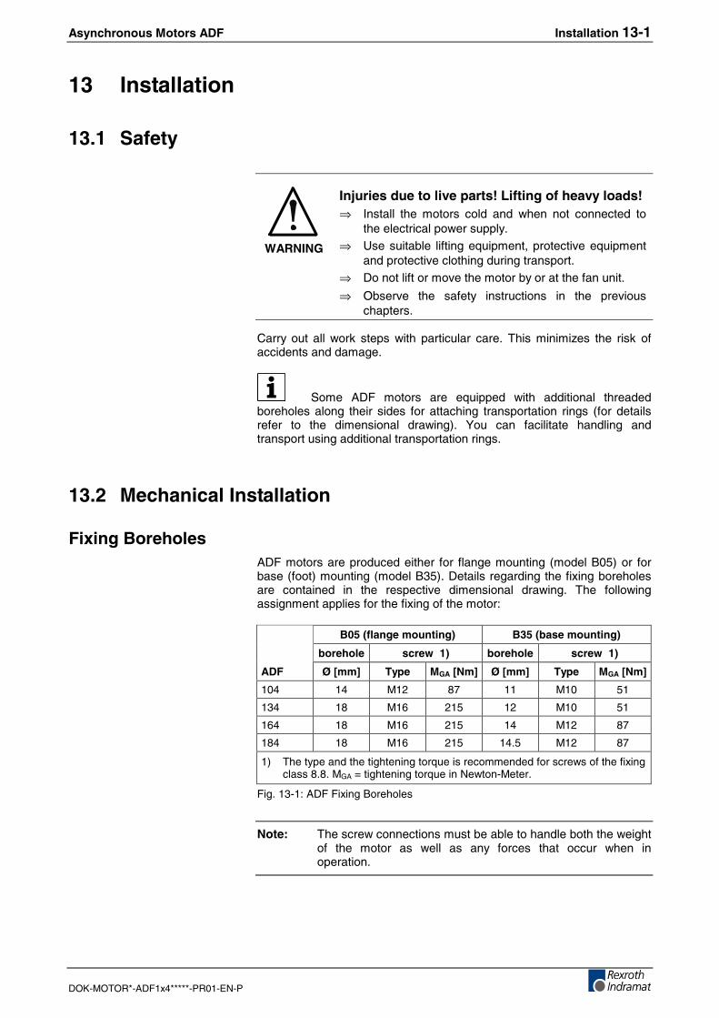
Asynchronous Motors ADF Installation 13-1
DOK-MOTOR*-ADF1x4*****-PR01-EN-P
13 Installation
13.1 Safety
WARNING
Injuries due to live parts! Lifting of heavy loads!⇒ Install the motors cold and when not connected to
the electrical power supply.⇒ Use suitable lifting equipment, protective equipment
and protective clothing during transport.⇒ Do not lift or move the motor by or at the fan unit.
⇒ Observe the safety instructions in the previouschapters.
Carry out all work steps with particular care. This minimizes the risk ofaccidents and damage.
Some ADF motors are equipped with additional threadedboreholes along their sides for attaching transportation rings (for detailsrefer to the dimensional drawing). You can facilitate handling andtransport using additional transportation rings.
13.2 Mechanical Installation
Fixing BoreholesADF motors are produced either for flange mounting (model B05) or forbase (foot) mounting (model B35). Details regarding the fixing boreholesare contained in the respective dimensional drawing. The followingassignment applies for the fixing of the motor:
B05 (flange mounting) B35 (base mounting)
borehole screw 1) borehole screw 1)
ADF Ø [mm] Type MGA [Nm] Ø [mm] Type MGA [Nm]
104 14 M12 87 11 M10 51
134 18 M16 215 12 M10 51
164 18 M16 215 14 M12 87
184 18 M16 215 14.5 M12 87
1) The type and the tightening torque is recommended for screws of the fixingclass 8.8. MGA = tightening torque in Newton-Meter.
Fig. 13-1: ADF Fixing Boreholes
Note: The screw connections must be able to handle both the weightof the motor as well as any forces that occur when inoperation.
13-2 Installation Asynchronous Motors ADF
DOK-MOTOR*-ADF1x4*****-PR01-EN-P
Preparations⇒ Log all of the measures carried out in the commissioning protocol.⇒ Assemble required accessories such as the "labyrinth seal" (SUP-
M02-ADF...) or the cooling tube joints before mounting the motor. Theassembly instructions for the labyrinth seal are contained in theaccessories set.
Prepare the mounting of the motor as follows:
1. Check whether any components have any visible damages. Damagedparts must not be assembled.
2. Make sure that dimensions and tolerances at the machine aresuitable for installing the motor (for details refer to the dimensionaldrawing).
3. Make sure that the assembly is carried out in clean and dryenvironment.
4. Have tools and required accessories ready, as well as measuring andtest equipment.
5. Check all components, assembly surfaces and threads forcleanliness.
6. Make sure that the seat for the motor flange at the machine is free ofburrs.
7. Remove the sleeve from the motor shaft. Store the sleeve for lateruse.
Mounting⇒ Mount the motor and fix all screws with the dedicated tightening
torque.
Observe the following:
⇒ Avoid blocking or sticking of the centering collar at the motor end.⇒ Avoid damages to the attachment fitting at the machine.⇒ Observe the permissible tightening torque for screw connections.⇒ Check the tightness and accuracy of the connection before carrying
out any other steps.⇒ Check the connection and setting of the cooling system⇒ When required, deair the cooling circuit according to the instructions
of the manufacturer.
After correct mechanical assembly, proceed with the electricalconnection.
Asynchronous Motors ADF Installation 13-3
DOK-MOTOR*-ADF1x4*****-PR01-EN-P
13.3 Electrical Connection
Preferably use the ready-made cables from REXROTH INDRAMAT.These cables have many advantages such as UL/CSA certification,extreme loadability and resistance as well as EMC conformity.
⇒ Carry out the electrical connection of the ADF motor as specified inthe chapter entitled "Connections".
Note:
• When assembling cables yourself, make sure that theseare designed and installed in conformity to the EMCrequirements.
• The connection plans of the product documentation areused in writing up the machine circuit diagrams. Themachine circuit diagrams of the machine manufacturer aresolely determinative for the connection of the drivecomponents in the machine.
• ADF104, 134, 164 and 184 are generally suitable for drivecombinations of the DIAX04 and ECODRIVE productranges with higher DC-bus voltage (up to 750V).
13-4 Installation Asynchronous Motors ADF
DOK-MOTOR*-ADF1x4*****-PR01-EN-P
Asynchronous Motors ADF Operation of ADF Motors 14-1
DOK-MOTOR*-ADF1x4*****-PR01-EN-P
14 Operation of ADF Motors
14.1 Commissioning
The following commissioning instructions refer to the ADF motor as partof a drive system with drive controller and control system.
Preparations1. Have the documentation of all products used at hand.2. Log all of the measures carried out in the commissioning protocol.3. Check the products for damages.4. Check all mechanical and electrical connections.5. Activate safety equipment and monitoring systems within the system.
CAREFUL
Equipment damage due to errors in the controlof motors and moved elements! Unclearoperating conditions and product data!⇒ Do not put into operation when connections,
operating conditions or product data are unclear orfaulty!
⇒ Do not put into operation when safety equipment andmonitoring equipment of the system are damaged ornot in operation.
⇒ Damaged products must not be put into operation.
⇒ Request missing information or support forcommissioning from REXROTH INDRAMAT!
ActionsWhen all requirements have been fulfilled, carry out the followingsteps:
1. Activate the external cooling system for the supply of the ADF motorand check its condition of order. Observe the instructions of thecooling system manufacturer.
2. Put the control units and power supplies into operation in accordanceto the respective instructions. Observe the respective productdocumentation.
3. Before enabling the command set-points, check whether theprogrammed ratio between the maximum speed of the motor and thecontroller set-point corresponds to the specifications of the machine.
4. At low speed, check whether the direction of rotation of the motor andthe command set-point polarity correspond to the specifications forthe machine.
5. At low speed, check whether the positioning commands of the controlsystem are correctly executed.
6. Log all of the measures carried out in the commissioning protocol.
When all steps have been carried out correctly, the commissioningof the motor has been completed.
14-2 Operation of ADF Motors Asynchronous Motors ADF
DOK-MOTOR*-ADF1x4*****-PR01-EN-P
The commissioning of drive controllers and control systems maymake other steps necessary. The check of functions and performance ofsystems is not a part of the motor commissioning but is carried out withinthe general start-up of the machine. Observe the details and regulationsof the machine manufacturer.
14.2 Shutdown
Carry out the following steps during faults, maintenance work or ashutdown of the motor:
1. Observe the instructions in the machine documentation.2. Use machine control commands to bring the drive to a controlled
standstill.3. Switch off the power and control voltage of the control unit.4. Switch off the motor protection switch for the motor fan.5. Switch off the main switch of the machine.6. Secure the machine against unforeseen movements and against
operation by unauthorized persons.7. Wait for the discharge time of the electrical systems and then
disconnect all electrical connections.8. Secure the motor and supply lines against falling or moving before
you disconnected the mechanical connections.9. Log all of the measures carried out in the commissioning protocol or
machine maintenance plan.
14.3 Disassembly
DANGER
Lethal injuries due to errors in the control ofmotors and work at moved elements!⇒ Do not work at systems that are running or that are
unsecured.⇒ Before disassembly, secure the machine against
unforeseen movements and against operation byunauthorized persons.
⇒ Secure the motor and supply lines against falling ormoving before you disconnect the mechanicalconnections.
1. Observe the instructions in the machine documentation.2. Observe the safety instructions and carry out all steps in accordance
to the previous instructions "14.2 Shutdown".3. Disassembly the motor from the machine and store it correctly.4. Log all of the measures carried out in the commissioning protocol or
machine maintenance plan.
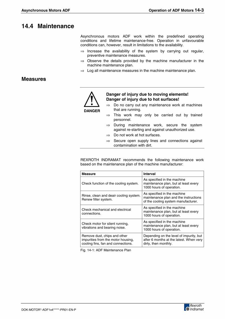
Asynchronous Motors ADF Operation of ADF Motors 14-3
DOK-MOTOR*-ADF1x4*****-PR01-EN-P
14.4 Maintenance
Asynchronous motors ADF work within the predefined operatingconditions and lifetime maintenance-free. Operation in unfavourableconditions can, however, result in limitations to the availability.
⇒ Increase the availability of the system by carrying out regular,preventive maintenance measures.
⇒ Observe the details provided by the machine manufacturer in themachine maintenance plan.
⇒ Log all maintenance measures in the machine maintenance plan.
Measures
DANGER
Danger of injury due to moving elements!Danger of injury due to hot surfaces!⇒ Do no carry out any maintenance work at machines
that are running.⇒ This work may only be carried out by trained
personnel.⇒ During maintenance work, secure the system
against re-starting and against unauthorized use.⇒ Do not work at hot surfaces.
⇒ Secure open supply lines and connections againstcontamination with dirt.
REXROTH INDRAMAT recommends the following maintenance workbased on the maintenance plan of the machine manufacturer:
Measure Interval
Check function of the cooling system.As specified in the machinemaintenance plan, but at least every1000 hours of operation.
Rinse, clean and deair cooling system.Renew filter system.
As specified in the machinemaintenance plan and the instructionsof the cooling system manufacturer.
Check mechanical and electricalconnections.
As specified in the machinemaintenance plan, but at least every1000 hours of operation.
Check motor for silent running,vibrations and bearing noise.
As specified in the machinemaintenance plan, but at least every1000 hours of operation.
Remove dust, chips and otherimpurities from the motor housing,cooling fins, fan and connections.
Depending on the level of impurity, butafter 6 months at the latest. When verydirty, then monthly.
Fig. 14-1: ADF Maintenance Plan
14-4 Operation of ADF Motors Asynchronous Motors ADF
DOK-MOTOR*-ADF1x4*****-PR01-EN-P
14.5 Troubleshooting
DANGER
Danger of injury due to moved elements!Danger of injury due to hot surfaces!⇒ Do no carry out any maintenance work at machines
that are running.⇒ Switch off control unit and machine and wait for the
discharge time of the electrical systems beforebeginning with the fault clearance.
⇒ During maintenance work, secure the systemagainst re-starting and against unauthorized use.
⇒ Do not work at hot surfaces.
The possible causes for faults at ADF motors can be limited to thefollowing areas:
• Motor encoder or encoder connection
• Internal winding temperature sensor
• Cooling system
• Mechanical damage to the motor
• Mechanical connection to the machine
The encoder and temperature sensor are monitored by the drivecontroller or the control system and appropriate diagnoses are shown.Observe the instructions of the respective documentation.
In the following, some fault examples are shown with potential causesand work-arounds, without any claims to completeness.
Excessive Temperature at the Motor HousingThe housing temperature of the motor increases to abnormally highvalues.
1. Breakdown or fault in the cooling system.
2. Original processing cycle has been changed.
3. Original motor parameters have been changed.
4. Motor bearing is worn-out or defective.
1. Check the cooling system. Clean or rinse the cooling circuit asrequired. Contact the machine manufacturer if the cooling systembreaks down.
2. Check drive sizing and selection for changed requirements. Do notcontinue work during overloads. Danger of damage!
3. Re-establish the original parameters. Check sizing of drive whenrequirements have been changed.
4. Compare total motor operating period with available bearing lifetimeand grease life. Slowly turn the motor shaft manually and check forany bearing noises or vibrations. Contact REXROTH INDRAMATService on a breakdown.
Condition
Possible Causes
Countermeasures
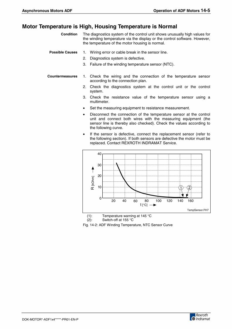
Asynchronous Motors ADF Operation of ADF Motors 14-5
DOK-MOTOR*-ADF1x4*****-PR01-EN-P
Motor Temperature is High, Housing Temperature is NormalThe diagnostics system of the control unit shows unusually high values forthe winding temperature via the display or the control software. However,the temperature of the motor housing is normal.
1. Wiring error or cable break in the sensor line.
2. Diagnostics system is defective.
3. Failure of the winding temperature sensor (NTC).
1. Check the wiring and the connection of the temperature sensoraccording to the connection plan.
2. Check the diagnostics system at the control unit or the controlsystem.
3. Check the resistance value of the temperature sensor using amultimeter.
• Set the measuring equipment to resistance measurement.
• Disconnect the connection of the temperature sensor at the controlunit and connect both wires with the measuring equipment (thesensor line is thereby also checked). Check the values according tothe following curve.
• If the sensor is defective, connect the replacement sensor (refer tothe following section). If both sensors are defective the motor must bereplaced. Contact REXROTH INDRAMAT Service.
100 120 140 160
21R [k
Ohm
]
t [°C]
10
20
30
0
40
20 40 60 80
TempSensor.FH7
(1): Temperature warning at 145 °C(2): Switch-off at 155 °C
Fig. 14-2: ADF Winding Temperature, NTC Sensor Curve
Condition
Possible Causes
Countermeasures
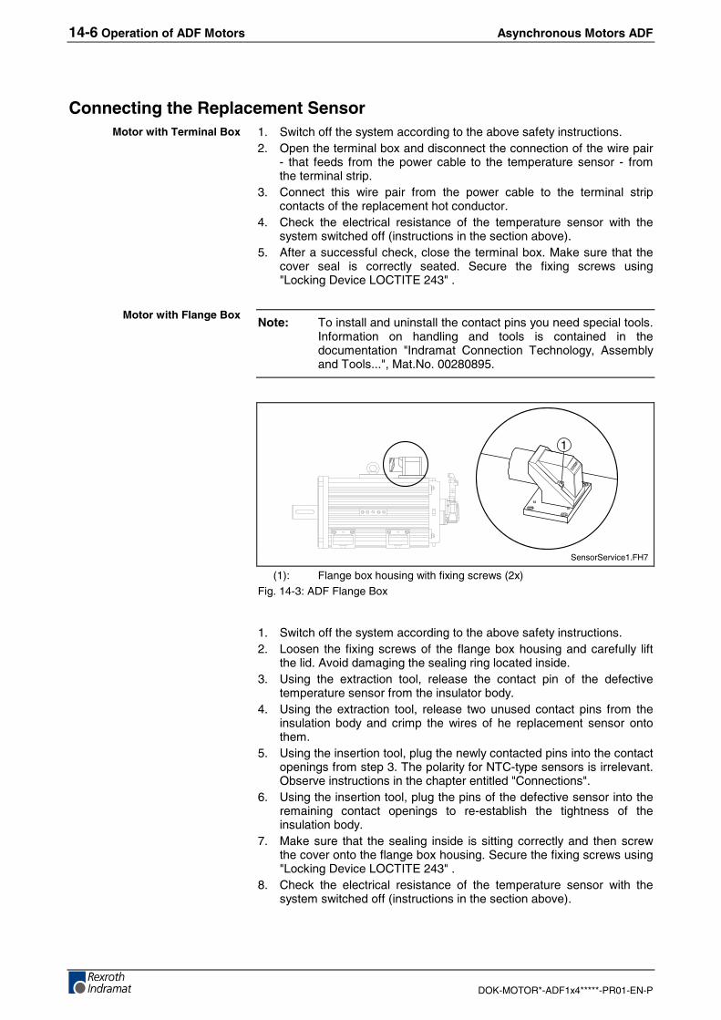
14-6 Operation of ADF Motors Asynchronous Motors ADF
DOK-MOTOR*-ADF1x4*****-PR01-EN-P
Connecting the Replacement Sensor1. Switch off the system according to the above safety instructions.2. Open the terminal box and disconnect the connection of the wire pair
- that feeds from the power cable to the temperature sensor - fromthe terminal strip.
3. Connect this wire pair from the power cable to the terminal stripcontacts of the replacement hot conductor.
4. Check the electrical resistance of the temperature sensor with thesystem switched off (instructions in the section above).
5. After a successful check, close the terminal box. Make sure that thecover seal is correctly seated. Secure the fixing screws using"Locking Device LOCTITE 243" .
Note: To install and uninstall the contact pins you need special tools.Information on handling and tools is contained in thedocumentation "Indramat Connection Technology, Assemblyand Tools...", Mat.No. 00280895.
1
SensorService1.FH7
(1): Flange box housing with fixing screws (2x)Fig. 14-3: ADF Flange Box
1. Switch off the system according to the above safety instructions.2. Loosen the fixing screws of the flange box housing and carefully lift
the lid. Avoid damaging the sealing ring located inside.3. Using the extraction tool, release the contact pin of the defective
temperature sensor from the insulator body.4. Using the extraction tool, release two unused contact pins from the
insulation body and crimp the wires of he replacement sensor ontothem.
5. Using the insertion tool, plug the newly contacted pins into the contactopenings from step 3. The polarity for NTC-type sensors is irrelevant.Observe instructions in the chapter entitled "Connections".
6. Using the insertion tool, plug the pins of the defective sensor into theremaining contact openings to re-establish the tightness of theinsulation body.
7. Make sure that the sealing inside is sitting correctly and then screwthe cover onto the flange box housing. Secure the fixing screws using"Locking Device LOCTITE 243" .
8. Check the electrical resistance of the temperature sensor with thesystem switched off (instructions in the section above).
Motor with Terminal Box
Motor with Flange Box
Asynchronous Motors ADF Operation of ADF Motors 14-7
DOK-MOTOR*-ADF1x4*****-PR01-EN-P
Motor generates VibrationsVibrations can be heard or felt at the motor.
1. Driven machine elements are insufficiently balanced or not balancedor insufficiently connected.
2. Motor bearing is worn-out or defective. The existing bearing lifetime orgrease life has expired.
3. Motor fixing has become loose
4. Drive system control loop is unstable.
1. Check the balancing of driven machine elements. Check the key andthe keyway. Contact REXROTH INDRAMAT Service if they aredamaged.
2. Check the motor for damages. Contact REXROTH INDRAMATService on a breakdown.
3. Fix the motor correctly and check for damages. Contact REXROTHINDRAMAT Service on a breakdown.
4. Check the parameterization of the drive system (motor and encoderdata). Observe the instructions in the drive controller documentation.
Preset Position is not ReachedPositioning command from the control system has not been executedexactly or at all. No fault display at the control unit or the control system.
1. Wiring of the encoder cable is faulty or defective. Pin assignment(encoder signal) in the cable or the plug has possibly been swapped.
2. Shielding of the encoder cable against interference signals isinsufficient.
3. Parameterization of the encoder data in the control unit is faulty.
4. Connection between the motor shaft and the machine element hasbecome loose.
5. Encoder is defective.
1. Check wiring according to the connection plan and the cable conditionfor damages.
2. Check the shielding; when necessary, enlarge the contact surfaces ofthe shielding.
3. Correct the parameters. Observe the commissioning protocol.
4. Check the mechanical connection. Do not reuse damaged parts.
5. The motor or the encoder must be replaced. Contact REXROTHINDRAMAT Service on a breakdown.
Various other faults and malfunctions, which do not belong to themotor documentation, might appear in a complex drive & control system.Contact REXROTH INDRAMAT helpdesk and service lines for furtherassistance. Phone numbers and contacts are listed in the followingchapter.
Condition
Possible Causes
Countermeasures
Condition
Possible Causes
Countermeasures
14-8 Operation of ADF Motors Asynchronous Motors ADF
DOK-MOTOR*-ADF1x4*****-PR01-EN-P
Asynchronous Motors ADF Service & Support 15-1
DOK-MOTOR*-ADF1x4*****-PR01-EN-P
15 Service & Support
15.1 Helpdesk
Unser Kundendienst-Helpdesk im Hauptwerk Lohram Main steht Ihnen mit Rat und Tat zur Seite.Sie erreichen uns
- telefonisch: +49 (0) 9352 40 50 60über Service Call Entry Center Mo-Fr 07:00-18:00
- per Fax: +49 (0) 9352 40 49 41
- per e-Mail: [email protected]
Our service helpdesk at our headquarters in Lohr amMain, Germany can assist you in all kinds of inquiries.Contact us
- by phone: +49 (0) 9352 40 50 60via Service Call Entry Center Mo-Fr 7:00 am - 6:00 pm
- by fax: +49 (0) 9352 40 49 41
- by e-mail: [email protected]
15.2 Service-Hotline
Außerhalb der Helpdesk-Zeiten ist der Servicedirekt ansprechbar unter
+49 (0) 171 333 88 26oder +49 (0) 172 660 04 06
After helpdesk hours, contact our servicedepartment directly at
+49 (0) 171 333 88 26or +49 (0) 172 660 04 06
15.3 Internet
Ergänzende Hinweise zu Service, Reparatur undTraining sowie die aktuellen Adressen unsererService- und Vertriebsbüros finden Sie unterwww.indramat.de – einige Angaben in dieserDokumentation können inzwischen überholt sein.
Außerhalb Deutschlands nehmen Sie bitte zuerstKontakt mit Ihrem lokalen Ansprechpartner auf.
Verkaufsniederlassungen
Niederlassungen mit Kundendienst
Additional notes about service, repairs and trainingas well as the actual addresses of our sales- andservice facilities are available on the Internet atwww.indramat.de – some information in thisdocumentation may meanwhile be obsolete.
Please contact the sales & service offices in yourarea first.
sales agencies
offices providing service
15.4 Vor der Kontaktaufnahme... - Before contacting us...
Wir können Ihnen schnell und effizient helfen wennSie folgende Informationen bereithalten:
1. detaillierte Beschreibung der Störung und derUmstände.
2. Angaben auf dem Typenschild derbetreffenden Produkte, insbesondereTypenschlüssel und Seriennummern.
3. Tel.-/Faxnummern und e-Mail-Adresse, unterdenen Sie für Rückfragen zu erreichen sind.
For quick and efficient help, please have thefollowing information ready:
1. Detailed description of the failure andcircumstances.
2. Information on the type plate of the affectedproducts, especially type codes and serialnumbers.
3. Your phone/fax numbers and e-mail address,so we can contact you in case of questions.
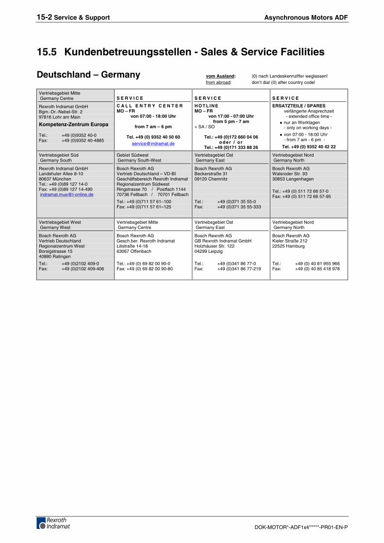
15-2 Service & Support Asynchronous Motors ADF
DOK-MOTOR*-ADF1x4*****-PR01-EN-P
15.5 Kundenbetreuungsstellen - Sales & Service Facilities
Deutschland – Germany vom Ausland: (0) nach Landeskennziffer weglassen!from abroad: don’t dial (0) after country code!
Vertriebsgebiet Mitte Germany Centre
Rexroth Indramat GmbHBgm.-Dr.-Nebel-Str. 297816 Lohr am Main
Kompetenz-Zentrum Europa
Tel.: +49 (0)9352 40-0Fax: +49 (0)9352 40-4885
S E R V I C E
C A L L E N T R Y C E N T E RMO – FR
von 07:00 - 18:00 Uhr
from 7 am – 6 pm
Tel. +49 (0) 9352 40 50 [email protected]
S E R V I C E
H O T L IN EMO – FR
von 17:00 - 07:00 Uhrfrom 5 pm - 7 am
+ SA / SO
Tel.: +49 (0)172 660 04 06o d er / o r
Tel.: +49 (0)171 333 88 26
S E R V I C E
ERSATZTEILE / SPARESverlängerte Ansprechzeit- extended office time -
g nur an Werktagen- only on working days -
g von 07:00 - 18:00 Uhr- from 7 am - 6 pm -
Tel. +49 (0) 9352 40 42 22
Vertriebsgebiet Süd Germany South
Rexroth Indramat GmbHLandshuter Allee 8-1080637 MünchenTel.: +49 (0)89 127 14-0Fax: +49 (0)89 127 14-490 [email protected]
Gebiet Südwest Germany South-West
Bosch Rexroth AGVertrieb Deutschland – VD-BIGeschäftsbereich Rexroth IndramatRegionalzentrum SüdwestRingstrasse 70 / Postfach 114470736 Fellbach / 70701 Fellbach
Tel.: +49 (0)711 57 61–100Fax: +49 (0)711 57 61–125
Vertriebsgebiet Ost Germany East
Bosch Rexroth AGBeckerstraße 3109120 Chemnitz
Tel.: +49 (0)371 35 55-0Fax: +49 (0)371 35 55-333
Vertriebsgebiet Nord Germany North
Bosch Rexroth AGWalsroder Str. 9330853 Langenhagen
Tel.: +49 (0) 511 72 66 57-0Fax: +49 (0) 511 72 66 57-95
Vertriebsgebiet West Germany West
Bosch Rexroth AGVertrieb DeutschlandRegionalzentrum WestBorsigstrasse 1540880 Ratingen
Tel.: +49 (0)2102 409-0Fax: +49 (0)2102 409-406
Vertriebsgebiet Mitte Germany Centre
Bosch Rexroth AGGesch.ber. Rexroth IndramatLilistraße 14-1863067 Offenbach
Tel.: +49 (0) 69 82 00 90-0Fax: +49 (0) 69 82 00 90-80
Vertriebsgebiet Ost Germany East
Bosch Rexroth AGGB Rexroth Indramat GmbHHolzhäuser Str. 12204299 Leipzig
Tel.: +49 (0)341 86 77-0Fax: +49 (0)341 86 77-219
Vertriebsgebiet Nord Germany North
Bosch Rexroth AGKieler Straße 21222525 Hamburg
Tel.: +49 (0) 40 81 955 966Fax: +49 (0) 40 85 418 978
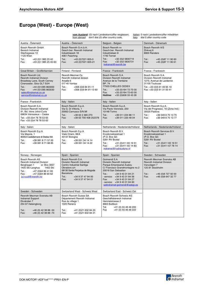
Asynchronous Motors ADF Service & Support 15-3
DOK-MOTOR*-ADF1x4*****-PR01-EN-P
Europa (West) - Europe (West)
vom Ausland: (0) nach Landeskennziffer weglassen, Italien: 0 nach Landeskennziffer mitwählenfrom abroad: don’t dial (0) after country code, Italy: dial 0 after country code
Austria - Österreich
Bosch Rexroth GmbHBereich IndramatStachegasse 131120 Wien
Tel.: +43 (0)1 985 25 40Fax: +43 (0)1 985 25 40-93
Austria – Österreich
Bosch Rexroth G.m.b.H.Gesch.ber. Rexroth IndramatIndustriepark 184061 Pasching
Tel.: +43 (0)7221 605-0Fax: +43 (0)7221 605-21
Belgium - Belgien
Bosch Rexroth nvGesch.ber. Rexroth IndramatIndustrielaan 81740 TernatTel.: +32 (0)2 5830719Fax: +32 (0)2 5830731 [email protected]
Denmark - Dänemark
Bosch Rexroth A/SZinkvej 68900 Randers
Tel.: +45 (0)87 11 90 60Fax: +45 (0)87 11 90 61
Great Britain – Großbritannien
Bosch Rexroth Ltd.Rexroth Indramat DivisionBroadway Lane, South CerneyCirencester, Glos GL7 5UHTel.: +44 (0)1285 863000Fax: +44 (0)1285 863030 [email protected] [email protected]
Finland - Finnland
Rexroth Mecman OyRexroth Indramat divisionAnsatie 6017 40 VantaaTel.: +358 (0)9 84 91-11Fax: +358 (0)9 84 91-13 60
France - Frankreich
Bosch Rexroth S.A.Division Rexroth IndramatAvenue de la TrentaineBP. 7477503 CHELLES CEDEXTel.: +33 (0)164 72-70 00Fax: +33 (0)164 72-63 00Hotline: +33 (0)608 33 43 28
France - Frankreich
Bosch Rexroth S.A.Division Rexroth Indramat1270, Avenue de Lardenne31100 ToulouseTel.: +33 (0)5 61 49 95 19Fax: +33 (0)5 61 31 00 41
France - Frankreich
Bosch Rexroth S.A.Division Rexroth Indramat91, Bd. Irène Joliot-Curie69634 Vénissieux – CedexTel.: +33 (0)4 78 78 53 65Fax: +33 (0)4 78 78 53 62
Italy - Italien
Bosch Rexroth S.p.A.Via G. Di Vittoria, 120063 Cernusco S/N.MITel.: +39 02 2 365 270Fax: +39 02 700 408 252378
Italy - Italien
Bosch Rexroth S.p.A.Via Paolo Veronesi, 25010148 TorinoTel.: +39 011 224 88 11Fax: +39 011 220 48 04
Italy - Italien
Bosch Rexroth S.p.A.Via del Progresso, 16 (Zona Ind.)35020 PadovaTel.: +39 049 8 70 13 70Fax: +39 049 8 70 13 77
Italy - Italien
Bosch Rexroth S.p.A.Via Mascia, 180053 Castellamare di Stabia NATel.: +39 081 8 71 57 00Fax: +39 081 8 71 68 85
Italy - Italien
Bosch Rexroth S.p.A.Viale Oriani, 38/A40137 BolognaTel.: +39 051 34 14 14Fax: +39 051 34 14 22
Netherlands - Niederlande/Holland
Bosch Rexroth B.V.Kruisbroeksestraat 1(P.O. Box 32)5281 RV BoxtelTel.: +31 (0)411 65 19 51Fax: +31 (0)411 65 14 83 [email protected]
Netherlands - Niederlande/Holland
Bosch Rexroth Services B.V.Kruisbroeksestraat 1(P.O. Box 32)5281 RV BoxtelTel.: +31 (0)411 65 19 51Fax: +31 (0)411 67 78 14
Norway - Norwegen
Bosch Rexroth ASRexroth Indramat DivisionBerghagan 1 or: Box 30071405 Ski-Langhus 1402 SkiTel.: +47 (0)64 86 41 00Fax: +47 (0)64 86 90 62 [email protected]
Spain - Spanien
Bosch Rexroth S.A.Divisiòn Rexroth IndramatCentro Industrial SantigaObradors s/n08130 Santa Perpetua de MogodaBarcelonaTel.: +34 9 37 47 94 00Fax: +34 9 37 47 94 01
Spain - Spanien
Goimendi S.A.División Rexroth IndramatParque Empresarial ZuatzuC/ Francisco Grandmontagne no.220018 San SebastianTel.: +34 9 43 31 84 21- service: +34 9 43 31 84 56Fax: +34 9 43 31 84 27- service: +34 9 43 31 84 60 [email protected]
Sweden - Schweden
Rexroth Mecman Svenska ABRexroth Indramat DivisionVaruvägen 7125 81 Stockholm
Tel.: +46 (0)8 727 92 00Fax: +46 (0)8 647 32 77
Sweden - Schweden
Rexroth Mecman Svenska ABIndramat SupportEkvändan 7254 67 Helsingborg
Tel.: +46 (0) 42 38 88 -50Fax: +46 (0) 42 38 88 -74
Switzerland West - Schweiz West
Bosch Rexroth Suisse SADépartement Rexroth IndramatRue du village 11020 Renens
Tel.: +41 (0)21 632 84 20Fax: +41 (0)21 632 84 21
Switzerland East - Schweiz Ost
Bosch Rexroth Schweiz AGGeschäftsbereich IndramatHemrietstrasse 28863 ButtikonTel. +41 (0) 55 46 46 205Fax +41 (0) 55 46 46 222
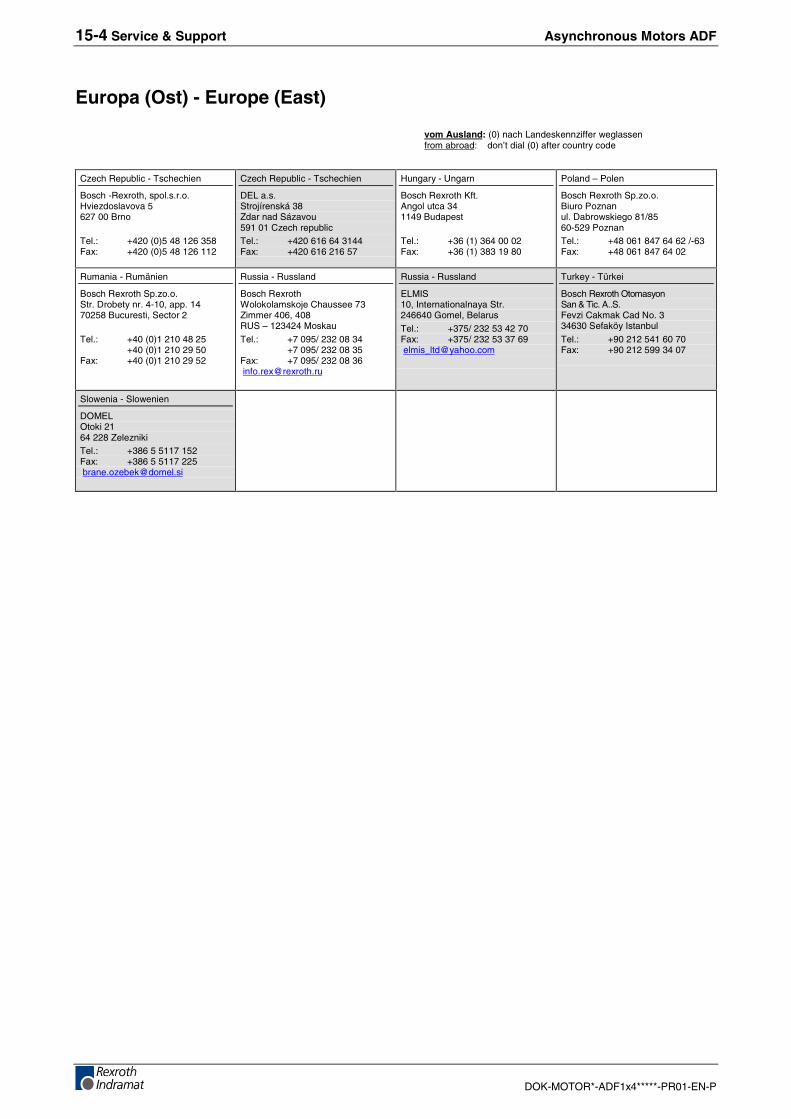
15-4 Service & Support Asynchronous Motors ADF
DOK-MOTOR*-ADF1x4*****-PR01-EN-P
Europa (Ost) - Europe (East)
vom Ausland: (0) nach Landeskennziffer weglassen from abroad: don’t dial (0) after country code
Czech Republic - Tschechien
Bosch -Rexroth, spol.s.r.o.Hviezdoslavova 5627 00 Brno
Tel.: +420 (0)5 48 126 358Fax: +420 (0)5 48 126 112
Czech Republic - Tschechien
DEL a.s.Strojírenská 38Zdar nad Sázavou591 01 Czech republicTel.: +420 616 64 3144Fax: +420 616 216 57
Hungary - Ungarn
Bosch Rexroth Kft.Angol utca 341149 Budapest
Tel.: +36 (1) 364 00 02Fax: +36 (1) 383 19 80
Poland – Polen
Bosch Rexroth Sp.zo.o.Biuro Poznanul. Dabrowskiego 81/8560-529 PoznanTel.: +48 061 847 64 62 /-63Fax: +48 061 847 64 02
Rumania - Rumänien
Bosch Rexroth Sp.zo.o.Str. Drobety nr. 4-10, app. 1470258 Bucuresti, Sector 2
Tel.: +40 (0)1 210 48 25+40 (0)1 210 29 50
Fax: +40 (0)1 210 29 52
Russia - Russland
Bosch RexrothWolokolamskoje Chaussee 73Zimmer 406, 408RUS – 123424 Moskau
Tel.: +7 095/ 232 08 34+7 095/ 232 08 35
Fax: +7 095/ 232 08 36 [email protected]
Russia - Russland
ELMIS10, Internationalnaya Str.246640 Gomel, Belarus
Tel.: +375/ 232 53 42 70Fax: +375/ 232 53 37 69 [email protected]
Turkey - Türkei
Bosch Rexroth OtomasyonSan & Tic. A..S.Fevzi Cakmak Cad No. 334630 Sefaköy Istanbul
Tel.: +90 212 541 60 70Fax: +90 212 599 34 07
Slowenia - Slowenien
DOMELOtoki 2164 228 ZeleznikiTel.: +386 5 5117 152Fax: +386 5 5117 225 [email protected]
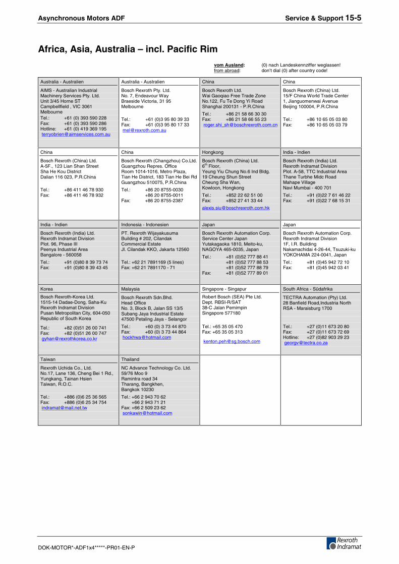
Asynchronous Motors ADF Service & Support 15-5
DOK-MOTOR*-ADF1x4*****-PR01-EN-P
Africa, Asia, Australia – incl. Pacific Rim
vom Ausland: (0) nach Landeskennziffer weglassen!from abroad: don’t dial (0) after country code!
Australia - Australien
AIMS - Australian IndustrialMachinery Services Pty. Ltd.Unit 3/45 Horne STCampbellfield , VIC 3061MelbourneTel.: +61 (0) 393 590 228Fax: +61 (0) 393 590 286Hotline: +61 (0) 419 369 195 [email protected]
Australia - Australien
Bosch Rexroth Pty. Ltd.No. 7, Endeavour WayBraeside Victoria, 31 95Melbourne
Tel.: +61 (0)3 95 80 39 33Fax: +61 (0)3 95 80 17 33 [email protected]
China
Bosch Rexroth Ltd.Wai Gaoqiao Free Trade ZoneNo.122, Fu Te Dong Yi RoadShanghai 200131 - P.R.China
Tel.: +86 21 58 66 30 30Fax: +86 21 58 66 55 23 [email protected]
China
Bosch Rexroth (China) Ltd.15/F China World Trade Center1, Jianguomenwai AvenueBeijing 100004, P.R.China
Tel.: +86 10 65 05 03 80Fax: +86 10 65 05 03 79
China
Bosch Rexroth (China) Ltd.A-5F., 123 Lian Shan StreetSha He Kou DistrictDalian 116 023, P.R.China
Tel.: +86 411 46 78 930Fax: +86 411 46 78 932
China
Bosch Rexroth (Changzhou) Co.Ltd.Guangzhou Repres. OfficeRoom 1014-1016, Metro Plaza,Tian He District, 183 Tian He Bei RdGuangzhou 510075, P.R.China
Tel.: +86 20 8755-0030+86 20 8755-0011
Fax: +86 20 8755-2387
Hongkong
Bosch Rexroth (China) Ltd.6th Floor,Yeung Yiu Chung No.6 Ind Bldg.19 Cheung Shun StreetCheung Sha Wan,Kowloon, Hongkong
Tel.: +852 22 62 51 00Fax: +852 27 41 33 44
India - Indien
Bosch Rexroth (India) Ltd.Rexroth Indramat DivisionPlot. A-58, TTC Industrial AreaThane Turbhe Midc RoadMahape VillageNavi Mumbai - 400 701
Tel.: +91 (0)22 7 61 46 22Fax: +91 (0)22 7 68 15 31
India - Indien
Bosch Rexroth (India) Ltd.Rexroth Indramat DivisionPlot. 96, Phase IIIPeenya Industrial AreaBangalore - 560058
Tel.: +91 (0)80 8 39 73 74Fax: +91 (0)80 8 39 43 45
Indonesia - Indonesien
PT. Rexroth WijayakusumaBuilding # 202, CilandakCommercial EstateJl. Cilandak KKO, Jakarta 12560
Tel.: +62 21 7891169 (5 lines)Fax: +62 21 7891170 - 71
Japan
Bosch Rexroth Automation Corp.Service Center JapanYutakagaoka 1810, Meito-ku,NAGOYA 465-0035, Japan
Tel.: +81 (0)52 777 88 41+81 (0)52 777 88 53+81 (0)52 777 88 79
Fax: +81 (0)52 777 89 01
Japan
Bosch Rexroth Automation Corp.Rexroth Indramat Division1F, I.R. BuildingNakamachidai 4-26-44, Tsuzuki-kuYOKOHAMA 224-0041, Japan
Tel.: +81 (0)45 942 72 10Fax: +81 (0)45 942 03 41
Korea
Bosch Rexroth-Korea Ltd.1515-14 Dadae-Dong, Saha-KuRexroth Indramat DivisionPusan Metropolitan City, 604-050Republic of South Korea
Tel.: +82 (0)51 26 00 741Fax: +82 (0)51 26 00 747 [email protected]
Malaysia
Bosch Rexroth Sdn.Bhd.Head OfficeNo. 3, Block B, Jalan SS 13/5Subang Jaya Industrial Estate47500 Petaling Jaya - Selangor
Tel.: +60 (0) 3 73 44 870Fax: +60 (0) 3 73 44 864 [email protected]
Singapore - Singapur
Robert Bosch (SEA) Pte Ltd.Dept. RBSI-R/SAT38-C Jalan PemimpinSingapore 577180
Tel.: +65 35 05 470Fax: +65 35 05 313
South Africa - Südafrika
TECTRA Automation (Pty) Ltd.28 Banfield Road,Industria NorthRSA - Maraisburg 1700
Tel.: +27 (0)11 673 20 80Fax: +27 (0)11 673 72 69Hotline: +27 (0)82 903 29 23 [email protected]
Taiwan
Rexroth Uchida Co., Ltd.No.17, Lane 136, Cheng Bei 1 Rd.,Yungkang, Tainan HsienTaiwan, R.O.C.
Tel.: +886 (0)6 25 36 565Fax: +886 (0)6 25 34 754 [email protected]
Thailand
NC Advance Technology Co. Ltd.59/76 Moo 9Ramintra road 34Tharang, Bangkhen,Bangkok 10230
Tel.: +66 2 943 70 62 +66 2 943 71 21Fax: +66 2 509 23 62 [email protected]
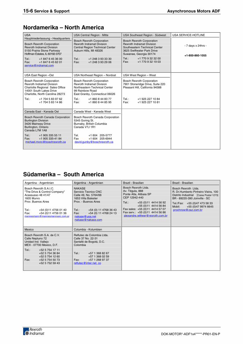
15-6 Service & Support Asynchronous Motors ADF
DOK-MOTOR*-ADF1x4*****-PR01-EN-P
Nordamerika – North AmericaUSAHauptniederlassung - Headquarters
Bosch Rexroth CorporationRexroth Indramat Division5150 Prairie Stone ParkwayHoffman Estates, IL 60192-3707
Tel.: +1 847 6 45 36 00Fax: +1 847 6 45 62 [email protected]
USA Central Region - Mitte
Bosch Rexroth CorporationRexroth Indramat DivisionCentral Region Technical CenterAuburn Hills, MI 48326
Tel.: +1 248 3 93 33 30Fax: +1 248 3 93 29 06
USA Southeast Region - Südwest
Bosch Rexroth CorporationRexroth Indramat DivisionSoutheastern Technical Center3625 Swiftwater Park DriveSuwanee, Georgia 30174
Tel.: +1 770 9 32 32 00Fax: +1 770 9 32 19 03
USA SERVICE-HOTLINE
- 7 days x 24hrs -
+1-800-860-1055
USA East Region –Ost
Bosch Rexroth CorporationRexroth Indramat DivisionCharlotte Regional Sales Office14001 South Lakes DriveCharlotte, North Carolina 28273
Tel.: +1 704 5 83 97 62+1 704 5 83 14 86
USA Northeast Region – Nordost
Bosch Rexroth CorporationRexroth Indramat DivisionNortheastern Technical Center99 Rainbow RoadEast Granby, Connecticut 06026
Tel.: +1 860 8 44 83 77Fax: +1 860 8 44 85 95
USA West Region – West
Bosch Rexroth Corporation7901 Stoneridge Drive, Suite 220Pleasant Hill, California 94588
Tel.: +1 925 227 10 84Fax: +1 925 227 10 81
Canada East - Kanada Ost
Bosch Rexroth Canada CorporationBurlington Division3426 Mainway DriveBurlington, OntarioCanada L7M 1A8
Tel.: +1 905 335 55 11Fax: +1 905 335-41 84 [email protected]
Canada West - Kanada West
Bosch Rexroth Canada Corporation5345 Goring St.Burnaby, British ColumbiaCanada V7J 1R1
Tel. +1 604 205-5777Fax +1 604 205-6944 [email protected]
Südamerika – South AmericaArgentina - Argentinien
Bosch Rexroth S.A.I.C."The Drive & Control Company"Acassusso 48 41/471605 MunroProv. Buenos Aires
Tel.: +54 (0)11 4756 01 40Fax: +54 (0)11 4756 01 [email protected]
Argentina - Argentinien
NAKASEServicio Tecnico CNCCalle 49, No. 5764/661653 Villa BalesterProv. - Buenos Aires
Tel.: +54 (0) 11 4768 36 43Fax: +54 (0) 11 4768 24 13 [email protected] [email protected]
Brazil - Brasilien
Bosch Rexroth Ltda.Av. Tégula, 888Ponte Alta, Atibaia SPCEP 12942-440
Tel.: +55 (0)11 4414 56 92+55 (0)11 4414 56 84
Fax sales: +55 (0)11 4414 57 07Fax serv.: +55 (0)11 4414 56 86 [email protected]
Brazil - Brasilien
Bosch Rexroth Ltda.R. Dr.Humberto Pinheiro Vieira, 100Distrito Industrial [Caixa Postal 1273]BR - 89220-390 Joinville - SC
Tel./Fax: +55 (0)47 473 58 33Mobil: +55 (0)47 9974 6645 [email protected]
Mexico
Bosch Rexroth S.A. de C.V.Calle Neptuno 72Unidad Ind. VallejoMEX - 07700 Mexico, D.F.
Tel.: +52 5 754 17 11+52 5 754 36 84+52 5 754 12 60
Fax: +52 5 754 50 73+52 5 752 59 43
Columbia - Kolumbien
Reflutec de Colombia Ltda.Calle 37 No. 22-31Santafé de Bogotá, D.C.Colombia
Tel.: +57 1 368 82 67+57 1 368 02 59
Fax: +57 1 268 97 [email protected]. co
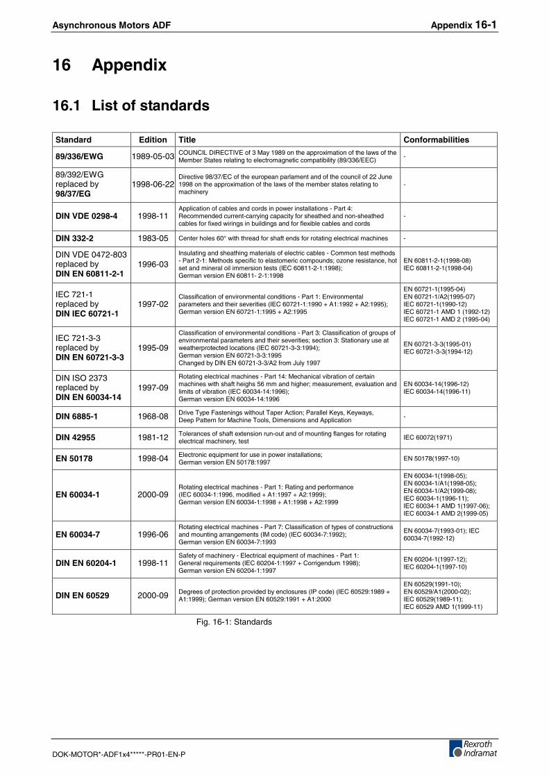
Asynchronous Motors ADF Appendix 16-1
DOK-MOTOR*-ADF1x4*****-PR01-EN-P
16 Appendix
16.1 List of standards
Standard Edition Title Conformabilities
89/336/EWG 1989-05-03 COUNCIL DIRECTIVE of 3 May 1989 on the approximation of the laws of theMember States relating to electromagnetic compatibility (89/336/EEC)
-
89/392/EWGreplaced by98/37/EG
1998-06-22Directive 98/37/EC of the european parlament and of the council of 22 June1998 on the approximation of the laws of the member states relating tomachinery
-
DIN VDE 0298-4 1998-11Application of cables and cords in power installations - Part 4:Recommended current-carrying capacity for sheathed and non-sheathedcables for fixed wirings in buildings and for flexible cables and cords
-
DIN 332-2 1983-05 Center holes 60° with thread for shaft ends for rotating electrical machines -
DIN VDE 0472-803replaced byDIN EN 60811-2-1
1996-03Insulating and sheathing materials of electric cables - Common test methods- Part 2-1: Methods specific to elastomeric compounds; ozone resistance, hotset and mineral oil immersion tests (IEC 60811-2-1:1998);German version EN 60811- 2-1:1998
EN 60811-2-1(1998-08)IEC 60811-2-1(1998-04)
IEC 721-1replaced byDIN IEC 60721-1
1997-02Classification of environmental conditions - Part 1: Environmentalparameters and their severities (IEC 60721-1:1990 + A1:1992 + A2:1995);German version EN 60721-1:1995 + A2:1995
EN 60721-1(1995-04)EN 60721-1/A2(1995-07)IEC 60721-1(1990-12)IEC 60721-1 AMD 1 (1992-12)IEC 60721-1 AMD 2 (1995-04)
IEC 721-3-3replaced byDIN EN 60721-3-3
1995-09
Classification of environmental conditions - Part 3: Classification of groups ofenvironmental parameters and their severities; section 3: Stationary use atweatherprotected locations (IEC 60721-3-3:1994);German version EN 60721-3-3:1995Changed by DIN EN 60721-3-3/A2 from July 1997
EN 60721-3-3(1995-01)IEC 60721-3-3(1994-12)
DIN ISO 2373replaced byDIN EN 60034-14
1997-09Rotating electrical machines - Part 14: Mechanical vibration of certainmachines with shaft heighs 56 mm and higher; measurement, evaluation andlimits of vibration (IEC 60034-14:1996);German version EN 60034-14:1996
EN 60034-14(1996-12)IEC 60034-14(1996-11)
DIN 6885-1 1968-08 Drive Type Fastenings without Taper Action; Parallel Keys, Keyways,Deep Pattern for Machine Tools, Dimensions and Application
-
DIN 42955 1981-12 Tolerances of shaft extension run-out and of mounting flanges for rotatingelectrical machinery, test
IEC 60072(1971)
EN 50178 1998-04 Electronic equipment for use in power installations;German version EN 50178:1997
EN 50178(1997-10)
EN 60034-1 2000-09Rotating electrical machines - Part 1: Rating and performance(IEC 60034-1:1996, modified + A1:1997 + A2:1999);German version EN 60034-1:1998 + A1:1998 + A2:1999
EN 60034-1(1998-05);EN 60034-1/A1(1998-05);EN 60034-1/A2(1999-08);IEC 60034-1(1996-11);IEC 60034-1 AMD 1(1997-06);IEC 60034-1 AMD 2(1999-05)
EN 60034-7 1996-06Rotating electrical machines - Part 7: Classification of types of constructionsand mounting arrangements (IM code) (IEC 60034-7:1992);German version EN 60034-7:1993
EN 60034-7(1993-01); IEC60034-7(1992-12)
DIN EN 60204-1 1998-11Safety of machinery - Electrical equipment of machines - Part 1:General requirements (IEC 60204-1:1997 + Corrigendum 1998);German version EN 60204-1:1997
EN 60204-1(1997-12);IEC 60204-1(1997-10)
DIN EN 60529 2000-09 Degrees of protection provided by enclosures (IP code) (IEC 60529:1989 +A1:1999); German version EN 60529:1991 + A1:2000
EN 60529(1991-10);EN 60529/A1(2000-02);IEC 60529(1989-11);IEC 60529 AMD 1(1999-11)
Fig. 16-1: Standards

16-2 Appendix Asynchronous Motors ADF
DOK-MOTOR*-ADF1x4*****-PR01-EN-P
Asynchronous Motors ADF Glossary 17-1
DOK-MOTOR*-ADF1x4*****-PR01-EN-P
17 Glossary
FeedbackTerm used by Rexroth Indramat for encoder systems. These includeincremental rotary encoders, geared encoders and resolvers. Example:Digital Servo Feedback DSF (Option "6" for ADF).
Deep-groove ball bearingUniversal type of bearing suitable for accepting low to medium radial andaxial forces. Low-noise when running. Suitability for high speeds. Part ofthe family of antifriction bearings. Standard bearing type for ADF motors.
Cylinder roller bearingSingle-row bearing design for the "reinforced bearing" option for acceptinghigher forces. Suitability for low speeds. Operation only permissible withpermanently operating radial force.
FeatherSame as "key". Standardized definition, refer to IEC 60050-411-43-14.Half-wedge balancing or "Balancing with Key" can result in disadvantagesin the application: When the hub length of the driven machine element isshorter than the length of the key nut then a remaining imbalance remainswhen the entire key is inserted..
NTCAbbreviation for "Negative Temperature Coefficient". General term fortemperature sensors based on electrical resistors with the following modeof operation: The higher the temperature the lower the electricalresistance.
17-2 Glossary Asynchronous Motors ADF
DOK-MOTOR*-ADF1x4*****-PR01-EN-P
Asynchronous Motors ADF Index 18-1
DOK-MOTOR*-ADF1x4*****-PR01-EN-P
18 Index
AAccessories 9-1ADF104
data sheet 5-1dimensions sheet 5-4grease life 5-5shaft load 5-6technical data 5-1type code 5-2
ADF134data sheet 6-1dimensions sheets 6-4grease life 6-7shaft load 6-8technical data 6-1type code 6-2
ADF164data sheet 7-1dimensions sheets 7-4grease life 7-5shaft load 7-6technical data 7-1type code 7-2
ADF184data sheet 8-1dimensions sheet 8-4grease life 8-5shaft load 8-6technical data 8-1type code 8-2
Ambient temperature 11-1Application
guidelines 11-1utilization 11-1
Appropriate useapplications 2-2Introduction 2-1
Axial load 11-14
BBalancing 11-10base assembly 13-1Bearing 4-4, 11-12
axial load 11-14breakdown 11-14cylinder roller bearing 11-12, 17-1deep-groove ball bearing 11-12, 17-1grease life 11-14lifetime 11-14, 11-15options 11-12radial forces 11-12radial load 11-13reinforced 11-12running friction 11-12selection 11-16wear 11-14
Brake 11-7connection 10-9energy 11-8load 11-8lock 11-7lock delay 11-7unlock 11-7
18-2 Index Asynchronous Motors ADF
DOK-MOTOR*-ADF1x4*****-PR01-EN-P
CCable selection 10-1Checks
customer checks 12-1factory checks 12-1high-voltage test 12-1
Class of protection 11-3Command set-point polarity 14-1Commissioning 14-1
protocol 14-1Condition on delivery 12-1Connections 10-1
angular connector 10-8bayonet joint 10-4brake 10-9connection thread 10-10cooling 4-3diameter 10-10encoder connection 10-8fittings 10-11, 10-12flange socket 10-4inlet 10-10motor cooling 10-10operating pressure 10-10outlet 10-10polarity 10-8power connection 10-2power flange box 10-3temperature sensor 10-9terminal board 10-6terminal box 10-5, 10-6terminal strip 10-6tube connection 10-12
Cooling 11-18additives 11-19coolant 11-18coolant temperature 11-19corrosion 11-18
Corrossion 12-2
DDisassembly 14-2Discharge time 14-2Documentation 1-3Drive shaft 4-4, 11-10
EElectrical connection, see also Connections 13-3Encoder 11-9, 17-1
compatibility 11-9connection 10-8, 11-9I²C interface 11-9incremental encoder 11-9multiturn 11-9single turn 11-9
Environmental conditions 11-2
FFan
direction of revolution 14-1maintenance 14-3
Feather, see also Key 17-1Feedback refer to Encoderflange assembly 13-1
Asynchronous Motors ADF Index 18-3
DOK-MOTOR*-ADF1x4*****-PR01-EN-P
GGlossary 17-1Grease life 11-12, 11-14, 11-15
HHandling 12-1High-voltage test, refer also to Checks 12-1Holding brake, see also Brake 4-3
IIdentification 12-2Imbalance 11-10Inappropriate use 2-2
Consequences, Discharge of liability 2-1Installation 11-4, 13-1
altitude 11-1base assembly 11-5mechanical 13-1safety 13-1vertical assembly 11-6, 11-11
Insulation resistance 12-1
KKey 4-4, 11-10
graded key 11-10Keyway 4-4, 11-10
LLabyrinth seal 9-1Length of motor 4-1Lifetime 11-14
MMaintenance 14-3
measures 14-3plan 14-3
Mean speed 11-13, 11-14Motor bearing, refer also to Bearing 11-12Motor encoder refer to EncoderMotor feedback refer to EncoderMotor size 4-1Mounting 13-2Mounting positions 11-4
NNTC 10-9, 11-17, 17-1
OOperating conditions 11-1Operation 14-1
Ppositioning command 14-1Power connection
output direction 4-2position 4-2
18-4 Index Asynchronous Motors ADF
DOK-MOTOR*-ADF1x4*****-PR01-EN-P
RRadial forces 11-5Radial shaft seal ring 11-11
SSafety Instructions for Electric Servo Drives and Controls 3-1Shaft end, Side B 4-4Shaft load 11-12Shaft seal ring 11-11Shocks 11-2Shutdown 14-2star connection 4-3Storage 12-2
TTemperature Sensor 11-17Terminal boxes refer to ConnectionsTightness 11-11Transport 12-1Troubleshooting 14-4Type code ADF 4-1Type plate 12-2
UUse See Appropriate use and inappropriate use
VVibration
level 11-17severity grade 4-4Sinusoidal 11-2speed 11-17
WWeight compensation 11-7Windings
code 4-3temperature 14-5
Asynchronous Motors ADF Index 18-5
DOK-MOTOR*-ADF1x4*****-PR01-EN-P

18-6 Index Asynchronous Motors ADF
DOK-MOTOR*-ADF1x4*****-PR01-EN-P


Prin
ted
inG
erm
any
0 0 2 7 3 9 3 4