linear technology psm apps frequently asked questions 1 ...ltpowerplay.com/help/psm-faq.pdf ·...
TRANSCRIPT

Linear Technology PSM Apps Frequently Asked Questions1. PSM Apps FAQs . . . . . . . . . . . . . . . . . . . . . . . . . . . . . . . . . . . . . . . . . . . . . . . . . . . . . . . . . . . . . . . . . . . . . . . . . . . . . . . . . . . . . . . . . . . . 4
1.1 Power System Managers . . . . . . . . . . . . . . . . . . . . . . . . . . . . . . . . . . . . . . . . . . . . . . . . . . . . . . . . . . . . . . . . . . . . . . . . . . . . . . . . . 71.1.1 How Can I Quickly determine if a LTC297x device has a CRC memory Error? . . . . . . . . . . . . . . . . . . . . . . . . . . . . . . . . . . . 81.1.2 How Do I Configure LTC2977/2978 Odd Channels for Current Measurement? . . . . . . . . . . . . . . . . . . . . . . . . . . . . . . . . . . . 101.1.3 How Do I Configure Unused LTC297x Channels? . . . . . . . . . . . . . . . . . . . . . . . . . . . . . . . . . . . . . . . . . . . . . . . . . . . . . . . . . 12
1.1.3.1 How much current can the LTC297x VDD33 regulator supply? . . . . . . . . . . . . . . . . . . . . . . . . . . . . . . . . . . . . . . . . . . 141.1.4 How Do VOUT_EN Pins Behave at Power-up? . . . . . . . . . . . . . . . . . . . . . . . . . . . . . . . . . . . . . . . . . . . . . . . . . . . . . . . . . . . 151.1.5 How much EEPROM does the LTC2977 have? . . . . . . . . . . . . . . . . . . . . . . . . . . . . . . . . . . . . . . . . . . . . . . . . . . . . . . . . . . . 161.1.6 How to Configure LTC297x to Only Monitor & Supervise Channels . . . . . . . . . . . . . . . . . . . . . . . . . . . . . . . . . . . . . . . . . . . . 171.1.7 Is it OK to Float Unused Inputs? . . . . . . . . . . . . . . . . . . . . . . . . . . . . . . . . . . . . . . . . . . . . . . . . . . . . . . . . . . . . . . . . . . . . . . . 191.1.8 Is it possible that EEPROM can be written/read only with VDD33 applied (no Vpwr supply)? . . . . . . . . . . . . . . . . . . . . . . . . 201.1.9 The Device reports a TON_MAX_FAULT, but the Rise Time of the Output is Fine. Why? . . . . . . . . . . . . . . . . . . . . . . . . . . 211.1.10 What replacement part is suggested for the PFET that powers LTC297x via USB dongle? . . . . . . . . . . . . . . . . . . . . . . . . 22
1.2 PSM Controllers . . . . . . . . . . . . . . . . . . . . . . . . . . . . . . . . . . . . . . . . . . . . . . . . . . . . . . . . . . . . . . . . . . . . . . . . . . . . . . . . . . . . . . . . 231.2.1 What causes the ADC Invalid bit in the MFR_PADS register to assert? . . . . . . . . . . . . . . . . . . . . . . . . . . . . . . . . . . . . . . . . . 241.2.2 Can LTpowerPlay Calculate Total Rail Current for Polyphase Rails Utilizing Extra non-PMBus 'Slave' Phases? . . . . . . . . . 251.2.3 Controlled Off . . . . . . . . . . . . . . . . . . . . . . . . . . . . . . . . . . . . . . . . . . . . . . . . . . . . . . . . . . . . . . . . . . . . . . . . . . . . . . . . . . . . . 261.2.4 How can I Determine if a Device is a LTC3880 vs. LTC3880-1 . . . . . . . . . . . . . . . . . . . . . . . . . . . . . . . . . . . . . . . . . . . . . . . 271.2.5 How do I set up PGOOD? . . . . . . . . . . . . . . . . . . . . . . . . . . . . . . . . . . . . . . . . . . . . . . . . . . . . . . . . . . . . . . . . . . . . . . . . . . . . 281.2.6 How do you read the ALERTB pin via PMBus? . . . . . . . . . . . . . . . . . . . . . . . . . . . . . . . . . . . . . . . . . . . . . . . . . . . . . . . . . . . 291.2.7 How long does it take for a PSM controller to reset? . . . . . . . . . . . . . . . . . . . . . . . . . . . . . . . . . . . . . . . . . . . . . . . . . . . . . . . 301.2.8 I have a need for a polyphase configuration that is not covered by the existing polyphase templates. What do I do? . . . . . . 311.2.9 I Observe Bad Temp Readings. What are the Possible Causes? . . . . . . . . . . . . . . . . . . . . . . . . . . . . . . . . . . . . . . . . . . . . . . 321.2.10 Misconnected Pins . . . . . . . . . . . . . . . . . . . . . . . . . . . . . . . . . . . . . . . . . . . . . . . . . . . . . . . . . . . . . . . . . . . . . . . . . . . . . . . . 331.2.11 My PSM Controller is pulling ALERTB low. Is there a way to mask certain faults? . . . . . . . . . . . . . . . . . . . . . . . . . . . . . . . 341.2.12 Overlapping Rail Address . . . . . . . . . . . . . . . . . . . . . . . . . . . . . . . . . . . . . . . . . . . . . . . . . . . . . . . . . . . . . . . . . . . . . . . . . . . 351.2.13 Storing user information in NVM . . . . . . . . . . . . . . . . . . . . . . . . . . . . . . . . . . . . . . . . . . . . . . . . . . . . . . . . . . . . . . . . . . . . . . 361.2.14 The part is reporting a PLL_UNLOCK fault. What are the Possible Causes? . . . . . . . . . . . . . . . . . . . . . . . . . . . . . . . . . . . . 371.2.15 What is the latency of a VOUT change? . . . . . . . . . . . . . . . . . . . . . . . . . . . . . . . . . . . . . . . . . . . . . . . . . . . . . . . . . . . . . . . . 381.2.16 What is the real OC value? . . . . . . . . . . . . . . . . . . . . . . . . . . . . . . . . . . . . . . . . . . . . . . . . . . . . . . . . . . . . . . . . . . . . . . . . . . 391.2.17 Why do I see a MFR (GPIOB_ASSERTED_LO) fault at power up? . . . . . . . . . . . . . . . . . . . . . . . . . . . . . . . . . . . . . . . . . . . 401.2.18 How do I set the temperature configuration when TSENSE pins are grounded on the LTC3882? . . . . . . . . . . . . . . . . . . . . 41
1.3 Supervisors . . . . . . . . . . . . . . . . . . . . . . . . . . . . . . . . . . . . . . . . . . . . . . . . . . . . . . . . . . . . . . . . . . . . . . . . . . . . . . . . . . . . . . . . . . . . 421.3.1 LTC2933 Apps FAQ . . . . . . . . . . . . . . . . . . . . . . . . . . . . . . . . . . . . . . . . . . . . . . . . . . . . . . . . . . . . . . . . . . . . . . . . . . . . . . . . 43
1.3.1.1 For the HIGH RANGE setting on pin V1 the comparator threshold can be programmed as high at 15v, but the Absolute Maximum rating for pin V1 is 14v, can I drive 15v into pin V1 in HIGH RANGE? . . . . . . . . . . . . . . . . . . . . . . . . . . . . . . . . . . . 44
1.3.1.2 How much hysteresis do the LTC2933/36 input comparators have? . . . . . . . . . . . . . . . . . . . . . . . . . . . . . . . . . . . . . . 451.3.1.3 If an application does not use GPI2 how should it be configured? . . . . . . . . . . . . . . . . . . . . . . . . . . . . . . . . . . . . . . . . 461.3.1.4 What are the configuration register settings for the "typical application" on page1 of the data sheet? . . . . . . . . . . . . . 471.3.1.5 What is the difference between using a GPIO as RSTb and ALERTb? . . . . . . . . . . . . . . . . . . . . . . . . . . . . . . . . . . . . 481.3.1.6 What registers are stored in EEPROM with a STORE_USER command? . . . . . . . . . . . . . . . . . . . . . . . . . . . . . . . . . . 491.3.1.7 Why can't LTpowerPlay write to the board after I load a project file? . . . . . . . . . . . . . . . . . . . . . . . . . . . . . . . . . . . . . . 501.3.1.8 Why does LTpowerPlay show data in reserved register bits? . . . . . . . . . . . . . . . . . . . . . . . . . . . . . . . . . . . . . . . . . . . . 51
1.3.2 LTC2937 Apps FAQ . . . . . . . . . . . . . . . . . . . . . . . . . . . . . . . . . . . . . . . . . . . . . . . . . . . . . . . . . . . . . . . . . . . . . . . . . . . . . . . . 521.3.2.1 How do I monitor a negative supply? . . . . . . . . . . . . . . . . . . . . . . . . . . . . . . . . . . . . . . . . . . . . . . . . . . . . . . . . . . . . . . 531.3.2.2 How do I use the fault log in the LTC2937? . . . . . . . . . . . . . . . . . . . . . . . . . . . . . . . . . . . . . . . . . . . . . . . . . . . . . . . . . 551.3.2.3 If the I2C bus is not used, how do I tie the pins on the board? . . . . . . . . . . . . . . . . . . . . . . . . . . . . . . . . . . . . . . . . . . . 571.3.2.4 What do I do with unused channels on the LTC2937? . . . . . . . . . . . . . . . . . . . . . . . . . . . . . . . . . . . . . . . . . . . . . . . . . 581.3.2.5 What happens if I place an un-programmed (factory default) LTC2937 on my board? . . . . . . . . . . . . . . . . . . . . . . . . . 591.3.2.6 What is the "boot-up" time of the LTC2937? . . . . . . . . . . . . . . . . . . . . . . . . . . . . . . . . . . . . . . . . . . . . . . . . . . . . . . . . . 601.3.2.7 Why is Linduino having trouble communicating with the DC2313A on the I2C bus? . . . . . . . . . . . . . . . . . . . . . . . . . . 61
1.3.3 LTC2936 Apps FAQ . . . . . . . . . . . . . . . . . . . . . . . . . . . . . . . . . . . . . . . . . . . . . . . . . . . . . . . . . . . . . . . . . . . . . . . . . . . . . . . . 621.3.3.1 Why is Linduino having trouble communicating with my DC1605B on the I2C bus? . . . . . . . . . . . . . . . . . . . . . . . . . . 63
1.3.4 "Add Default LTCXXXX Chip" button in LTpowerPlay does not add datasheet default register settings; why? . . . . . . . . . . . 641.4 LTpowerPlay FAQ . . . . . . . . . . . . . . . . . . . . . . . . . . . . . . . . . . . . . . . . . . . . . . . . . . . . . . . . . . . . . . . . . . . . . . . . . . . . . . . . . . . . . . . 65
1.4.1 Can I license LTpowerPlay if my computer is not connected to the internet? . . . . . . . . . . . . . . . . . . . . . . . . . . . . . . . . . . . . . 661.4.2 Can I have multiple versions of the GUI simultaneously installed on one computer? Can I 'snapshot' an old version of the GUI
before updating so that I can run the old version OR the new one? . . . . . . . . . . . . . . . . . . . . . . . . . . . . . . . . . . . . . . . . . . . . . . . . 681.4.3 How do I get detailed help for the selected register in LTpowerPlay? . . . . . . . . . . . . . . . . . . . . . . . . . . . . . . . . . . . . . . . . . . 691.4.4 How do I translate settings shown in to LTpowerPlay into I2C command sequences? . . . . . . . . . . . . . . . . . . . . . . . . . . . . . 711.4.5 Can LTpowerPlay Log Telemetry data to a file? . . . . . . . . . . . . . . . . . . . . . . . . . . . . . . . . . . . . . . . . . . . . . . . . . . . . . . . . . . . 721.4.6 Can I call LTpowerPlay from the command-line to program parts in system? . . . . . . . . . . . . . . . . . . . . . . . . . . . . . . . . . . . . 741.4.7 Can I use LTpowerPlay to run 'scripts' or sequences of I2C commands? . . . . . . . . . . . . . . . . . . . . . . . . . . . . . . . . . . . . . . . 751.4.8 Where do I download the Windows drivers for the DC1613A? . . . . . . . . . . . . . . . . . . . . . . . . . . . . . . . . . . . . . . . . . . . . . . . . 771.4.9 Can I use LTpowerPlay to decode raw fault log bytes read by my host controller? . . . . . . . . . . . . . . . . . . . . . . . . . . . . . . . . 781.4.10 How do I convert a project file containing multiple LTC2977 devices into LTM2987s? . . . . . . . . . . . . . . . . . . . . . . . . . . . . 801.4.11 Can I use LTpowerPlay to Merge Two Project Files into one? . . . . . . . . . . . . . . . . . . . . . . . . . . . . . . . . . . . . . . . . . . . . . . . 811.4.12 What does this error message encountered immediately after installation mean? . . . . . . . . . . . . . . . . . . . . . . . . . . . . . . . . 821.4.13 Can I use LTpowerPlay to compare two project (.proj) files? . . . . . . . . . . . . . . . . . . . . . . . . . . . . . . . . . . . . . . . . . . . . . . . . 841.4.14 How do I update LTpowerPlay on a machine without internet access? . . . . . . . . . . . . . . . . . . . . . . . . . . . . . . . . . . . . . . . . 851.4.15 Can I use my .license file on another computer? . . . . . . . . . . . . . . . . . . . . . . . . . . . . . . . . . . . . . . . . . . . . . . . . . . . . . . . . . 86

1.4.16 What does this error message, seen immediately after launching LTpowerPlay mean? . . . . . . . . . . . . . . . . . . . . . . . . . . . 871.4.17 How to I use LTpowerPlay to 'burn in' settings permanently into EEPROM . . . . . . . . . . . . . . . . . . . . . . . . . . . . . . . . . . . . . 881.4.18 Is there a simple way to read, decode and save all the fault logs on my board at one time? . . . . . . . . . . . . . . . . . . . . . . . . 891.4.19 My Views are Messed up. How can I recover to the default view configuration? . . . . . . . . . . . . . . . . . . . . . . . . . . . . . . . . . 911.4.20 I see LTpowerPlay in the taskbar, but I cannot see the window. How do I view the window? . . . . . . . . . . . . . . . . . . . . . . . 921.4.21 How do I Clear Individual Items In LTpowerplay? . . . . . . . . . . . . . . . . . . . . . . . . . . . . . . . . . . . . . . . . . . . . . . . . . . . . . . . . . 931.4.22 Is There an Easy Way to Review Large Configurations . . . . . . . . . . . . . . . . . . . . . . . . . . . . . . . . . . . . . . . . . . . . . . . . . . . . 941.4.23 I have a Register Command Code. Can LTpowerPlay tell me the Corresponding Register Name? . . . . . . . . . . . . . . . . . . 951.4.24 How Can I Quickly Search for a Register by Name? . . . . . . . . . . . . . . . . . . . . . . . . . . . . . . . . . . . . . . . . . . . . . . . . . . . . . . 961.4.25 How can a project file be used to program devices in a system . . . . . . . . . . . . . . . . . . . . . . . . . . . . . . . . . . . . . . . . . . . . . . 971.4.26 How Can I Stop LTpowerPlay's Polling Loop, or make the Dongle's SCL/SDA Lines HiZ . . . . . . . . . . . . . . . . . . . . . . . . . . 991.4.27 Can LTpowerPlay be run Without Administrative Priviliges, or Under a Non-admin Account? . . . . . . . . . . . . . . . . . . . . . . . 1001.4.28 Can I call LTpowerPlay from a batch file to program devices in-system? . . . . . . . . . . . . . . . . . . . . . . . . . . . . . . . . . . . . . . . 1011.4.29 When I click 'Add default LTCXXXX Chip', why do the settings not match the datasheet/factory defaults? . . . . . . . . . . . . . 1031.4.30 How do I get more information on the status/fault indicator XXXX? . . . . . . . . . . . . . . . . . . . . . . . . . . . . . . . . . . . . . . . . . . . 1041.4.31 LTpowerPlay requires .NET Framework v2.0, and my computer does not have this version. How do I get it? . . . . . . . . . . 1071.4.32 Can LTpowerPlay dump the contents of a device's EEPROM to a file? . . . . . . . . . . . . . . . . . . . . . . . . . . . . . . . . . . . . . . . . 1081.4.33 What is the syntax of scripts (command-files) in the I2C Utility? . . . . . . . . . . . . . . . . . . . . . . . . . . . . . . . . . . . . . . . . . . . . . . 109
1.5 Device Programming FAQ . . . . . . . . . . . . . . . . . . . . . . . . . . . . . . . . . . . . . . . . . . . . . . . . . . . . . . . . . . . . . . . . . . . . . . . . . . . . . . . . 1111.5.1 Can I program my PMBus Device over JTAG? . . . . . . . . . . . . . . . . . . . . . . . . . . . . . . . . . . . . . . . . . . . . . . . . . . . . . . . . . . . . 1121.5.2 Does BPM (or Arrow) Support my LTC device for programming? . . . . . . . . . . . . . . . . . . . . . . . . . . . . . . . . . . . . . . . . . . . . . 1141.5.3 How do I export the correct programming files from LTpowerPlay? . . . . . . . . . . . . . . . . . . . . . . . . . . . . . . . . . . . . . . . . . . . . 1161.5.4 How do I hook-up a dongle to my customer board? . . . . . . . . . . . . . . . . . . . . . . . . . . . . . . . . . . . . . . . . . . . . . . . . . . . . . . . . 1171.5.5 How to Decode a Standard Intel Hex File . . . . . . . . . . . . . . . . . . . . . . . . . . . . . . . . . . . . . . . . . . . . . . . . . . . . . . . . . . . . . . . . 1201.5.6 How to power device In-Circuit without powering the entire system? . . . . . . . . . . . . . . . . . . . . . . . . . . . . . . . . . . . . . . . . . . . 121
1.5.6.1 How Do I Program Controllers without VIN . . . . . . . . . . . . . . . . . . . . . . . . . . . . . . . . . . . . . . . . . . . . . . . . . . . . . . . . . . 1221.5.7 What's the difference between In-Flight Update (IFU) & In-Circuit Programming (ICP)? . . . . . . . . . . . . . . . . . . . . . . . . . . . . 1231.5.8 What are the different CRC Options Available? . . . . . . . . . . . . . . . . . . . . . . . . . . . . . . . . . . . . . . . . . . . . . . . . . . . . . . . . . . . 1241.5.9 What if I need more than 100mA from the USB PMBus Controller (i.e. DC1613A)? . . . . . . . . . . . . . . . . . . . . . . . . . . . . . . . 1261.5.10 What is the format of the LT Programming File? . . . . . . . . . . . . . . . . . . . . . . . . . . . . . . . . . . . . . . . . . . . . . . . . . . . . . . . . . . 1281.5.11 What is the Programming Power Circuit? . . . . . . . . . . . . . . . . . . . . . . . . . . . . . . . . . . . . . . . . . . . . . . . . . . . . . . . . . . . . . . . 1291.5.12 What options do I have for getting Programmed Devices? . . . . . . . . . . . . . . . . . . . . . . . . . . . . . . . . . . . . . . . . . . . . . . . . . . 1301.5.13 What Programming Option Should I choose? . . . . . . . . . . . . . . . . . . . . . . . . . . . . . . . . . . . . . . . . . . . . . . . . . . . . . . . . . . . . 1311.5.14 Where does LTpowerPlay store it's computed CRC in the part? . . . . . . . . . . . . . . . . . . . . . . . . . . . . . . . . . . . . . . . . . . . . . 1321.5.15 Where do I find In Flight Update Information? . . . . . . . . . . . . . . . . . . . . . . . . . . . . . . . . . . . . . . . . . . . . . . . . . . . . . . . . . . . . 1341.5.16 Why Must all Devices Share a Common Base Address for In System Programming to Work? . . . . . . . . . . . . . . . . . . . . . . 135
1.6 Firmware FAQ . . . . . . . . . . . . . . . . . . . . . . . . . . . . . . . . . . . . . . . . . . . . . . . . . . . . . . . . . . . . . . . . . . . . . . . . . . . . . . . . . . . . . . . . . . 1361.6.1 Can I print fault log data generated by my firmware? . . . . . . . . . . . . . . . . . . . . . . . . . . . . . . . . . . . . . . . . . . . . . . . . . . . . . . . 1371.6.2 Do I Need Polling? . . . . . . . . . . . . . . . . . . . . . . . . . . . . . . . . . . . . . . . . . . . . . . . . . . . . . . . . . . . . . . . . . . . . . . . . . . . . . . . . . 1381.6.3 How are Voltages and Current Represented in PMBus Commands? . . . . . . . . . . . . . . . . . . . . . . . . . . . . . . . . . . . . . . . . . . . 1391.6.4 How Can I Extend the Retention Time of PSM Devices . . . . . . . . . . . . . . . . . . . . . . . . . . . . . . . . . . . . . . . . . . . . . . . . . . . . . 1431.6.5 How can I write maintenance code without polling? . . . . . . . . . . . . . . . . . . . . . . . . . . . . . . . . . . . . . . . . . . . . . . . . . . . . . . . . 1451.6.6 How do I know when LTC388X STORE_USER_ALL is complete? . . . . . . . . . . . . . . . . . . . . . . . . . . . . . . . . . . . . . . . . . . . . 1481.6.7 Linduino FAQ . . . . . . . . . . . . . . . . . . . . . . . . . . . . . . . . . . . . . . . . . . . . . . . . . . . . . . . . . . . . . . . . . . . . . . . . . . . . . . . . . . . . . 152
1.6.7.1 Can I Read and Decode Fault Logs in Firmware? . . . . . . . . . . . . . . . . . . . . . . . . . . . . . . . . . . . . . . . . . . . . . . . . . . . . 1531.6.7.2 How Do I Connect a Linduino to a PSM DC? . . . . . . . . . . . . . . . . . . . . . . . . . . . . . . . . . . . . . . . . . . . . . . . . . . . . . . . . 1541.6.7.3 Is the Code Open Source? . . . . . . . . . . . . . . . . . . . . . . . . . . . . . . . . . . . . . . . . . . . . . . . . . . . . . . . . . . . . . . . . . . . . . . 1551.6.7.4 What about the Galileo Board? . . . . . . . . . . . . . . . . . . . . . . . . . . . . . . . . . . . . . . . . . . . . . . . . . . . . . . . . . . . . . . . . . . . 1561.6.7.5 What Arduino Boards Work? . . . . . . . . . . . . . . . . . . . . . . . . . . . . . . . . . . . . . . . . . . . . . . . . . . . . . . . . . . . . . . . . . . . . . 1571.6.7.6 What If I Want to Use Other I2C DC At The Same Time? . . . . . . . . . . . . . . . . . . . . . . . . . . . . . . . . . . . . . . . . . . . . . . . 1581.6.7.7 What Sketch's are Available? . . . . . . . . . . . . . . . . . . . . . . . . . . . . . . . . . . . . . . . . . . . . . . . . . . . . . . . . . . . . . . . . . . . . 159
1.6.8 MFR_SPECIAL_ID Handling . . . . . . . . . . . . . . . . . . . . . . . . . . . . . . . . . . . . . . . . . . . . . . . . . . . . . . . . . . . . . . . . . . . . . . . . . . 1601.6.8.1 How can firmware identify a LTC2978 without MFR_SPECIAL_ID? . . . . . . . . . . . . . . . . . . . . . . . . . . . . . . . . . . . . . . . 161
1.6.9 What Example Firmware is Available from LTC? . . . . . . . . . . . . . . . . . . . . . . . . . . . . . . . . . . . . . . . . . . . . . . . . . . . . . . . . . . 1631.6.10 What is In Flight Update and How do I use it? . . . . . . . . . . . . . . . . . . . . . . . . . . . . . . . . . . . . . . . . . . . . . . . . . . . . . . . . . . . 164
1.7 What's This Fault? . . . . . . . . . . . . . . . . . . . . . . . . . . . . . . . . . . . . . . . . . . . . . . . . . . . . . . . . . . . . . . . . . . . . . . . . . . . . . . . . . . . . . . . 1651.7.1 CML_INVALID_COMMAND . . . . . . . . . . . . . . . . . . . . . . . . . . . . . . . . . . . . . . . . . . . . . . . . . . . . . . . . . . . . . . . . . . . . . . . . . . 1661.7.2 CML_INVALID_DATA . . . . . . . . . . . . . . . . . . . . . . . . . . . . . . . . . . . . . . . . . . . . . . . . . . . . . . . . . . . . . . . . . . . . . . . . . . . . . . . 1671.7.3 CML_OTHER_COM_FAULT . . . . . . . . . . . . . . . . . . . . . . . . . . . . . . . . . . . . . . . . . . . . . . . . . . . . . . . . . . . . . . . . . . . . . . . . . . 1681.7.4 CML_PEC_FAILED . . . . . . . . . . . . . . . . . . . . . . . . . . . . . . . . . . . . . . . . . . . . . . . . . . . . . . . . . . . . . . . . . . . . . . . . . . . . . . . . . 1691.7.5 DAC_SATURATED . . . . . . . . . . . . . . . . . . . . . . . . . . . . . . . . . . . . . . . . . . . . . . . . . . . . . . . . . . . . . . . . . . . . . . . . . . . . . . . . . 1701.7.6 DISCHARGE_FAULT . . . . . . . . . . . . . . . . . . . . . . . . . . . . . . . . . . . . . . . . . . . . . . . . . . . . . . . . . . . . . . . . . . . . . . . . . . . . . . . 1721.7.7 FACTORY_TRIM_CRC_FAULT . . . . . . . . . . . . . . . . . . . . . . . . . . . . . . . . . . . . . . . . . . . . . . . . . . . . . . . . . . . . . . . . . . . . . . . 1741.7.8 FAULT0_IN . . . . . . . . . . . . . . . . . . . . . . . . . . . . . . . . . . . . . . . . . . . . . . . . . . . . . . . . . . . . . . . . . . . . . . . . . . . . . . . . . . . . . . . 1751.7.9 FAULT1_IN . . . . . . . . . . . . . . . . . . . . . . . . . . . . . . . . . . . . . . . . . . . . . . . . . . . . . . . . . . . . . . . . . . . . . . . . . . . . . . . . . . . . . . . 1781.7.10 FAULT_LOG_PRESENT . . . . . . . . . . . . . . . . . . . . . . . . . . . . . . . . . . . . . . . . . . . . . . . . . . . . . . . . . . . . . . . . . . . . . . . . . . . . 1801.7.11 GPIOB_ASSERTED_LO . . . . . . . . . . . . . . . . . . . . . . . . . . . . . . . . . . . . . . . . . . . . . . . . . . . . . . . . . . . . . . . . . . . . . . . . . . . . 1811.7.12 INPUT_OFF . . . . . . . . . . . . . . . . . . . . . . . . . . . . . . . . . . . . . . . . . . . . . . . . . . . . . . . . . . . . . . . . . . . . . . . . . . . . . . . . . . . . . . 1831.7.13 IOUT_OC_FAULT . . . . . . . . . . . . . . . . . . . . . . . . . . . . . . . . . . . . . . . . . . . . . . . . . . . . . . . . . . . . . . . . . . . . . . . . . . . . . . . . . 1851.7.14 OFF . . . . . . . . . . . . . . . . . . . . . . . . . . . . . . . . . . . . . . . . . . . . . . . . . . . . . . . . . . . . . . . . . . . . . . . . . . . . . . . . . . . . . . . . . . . . 1861.7.15 OT_FAULT . . . . . . . . . . . . . . . . . . . . . . . . . . . . . . . . . . . . . . . . . . . . . . . . . . . . . . . . . . . . . . . . . . . . . . . . . . . . . . . . . . . . . . 1871.7.16 PLL_UNLOCKED . . . . . . . . . . . . . . . . . . . . . . . . . . . . . . . . . . . . . . . . . . . . . . . . . . . . . . . . . . . . . . . . . . . . . . . . . . . . . . . . . 188

1.7.17 SHARE_CLK_LOW . . . . . . . . . . . . . . . . . . . . . . . . . . . . . . . . . . . . . . . . . . . . . . . . . . . . . . . . . . . . . . . . . . . . . . . . . . . . . . . . 1891.7.18 TON_MAX_FAULT . . . . . . . . . . . . . . . . . . . . . . . . . . . . . . . . . . . . . . . . . . . . . . . . . . . . . . . . . . . . . . . . . . . . . . . . . . . . . . . . 1911.7.19 UT_FAULT . . . . . . . . . . . . . . . . . . . . . . . . . . . . . . . . . . . . . . . . . . . . . . . . . . . . . . . . . . . . . . . . . . . . . . . . . . . . . . . . . . . . . . 1921.7.20 VOUT_OV_FAULT . . . . . . . . . . . . . . . . . . . . . . . . . . . . . . . . . . . . . . . . . . . . . . . . . . . . . . . . . . . . . . . . . . . . . . . . . . . . . . . . 1931.7.21 VOUT_UV_FAULT . . . . . . . . . . . . . . . . . . . . . . . . . . . . . . . . . . . . . . . . . . . . . . . . . . . . . . . . . . . . . . . . . . . . . . . . . . . . . . . . 194
1.8 Design . . . . . . . . . . . . . . . . . . . . . . . . . . . . . . . . . . . . . . . . . . . . . . . . . . . . . . . . . . . . . . . . . . . . . . . . . . . . . . . . . . . . . . . . . . . . . . . . 1951.8.1 How do you design the addressing of a PSM system? . . . . . . . . . . . . . . . . . . . . . . . . . . . . . . . . . . . . . . . . . . . . . . . . . . . . . . 196

Linear Technology Confidential
Preliminary Documentation - Subject to Change
PSM Apps FAQs
PSM Apps Frequently Asked Questions (FAQs)
How to use this FAQThis Document Contains PSM Applications Support Frequently Asked Questions Organized into Topic Areas. This document lists the commonquestions by topic area in a hierarchy or tree. There are a couple of ways to use this document:
Just search for keywords (CTRL+F, and type search term)New Folks: If you are not yet familiar with the document, you can use the index on the first pages of this document to see a treehierarchy complete listing of all content, with page numbers and hyperlinks to specific questions
You can browse the index by topic and Click the question of interest to navigate to that specific question/answer
Frequent Flyers: If you are already familiar with this document, consult the 'Most Recent FAQ Entries' list below to scan for recentlyadded content.
NOTE: Please forgive formatting errors, as this document is automatically generated from an internal website and as such may not be formattedperfectly. If you have questions about specific products or topics, please use the Help menu in LTpowerPlay to submit your question to theappropriate support person:
If you have quesitons that this FAQ does not yet answer, please use the Help menu within LTpowerPlay to send email to the specific group thatsupports your topic area:
Acknowledgement of ContributorsThis FAQ document is a work in progress. Multiple authors have contributed to the content. Below is a listing of the author contributions:
User Last Update Edits
Michael Holloway less than a minute ago 108
Nathan Enger 195 days ago 31
Michael Jones 154 days ago 30
Linear Technology Confidential
Preliminary Documentation - Subject to Change
Nicholas Vergunst 1022 days ago 15
Mike Peters 80 days ago 12
Haoran Wu 108 days ago 1
Most Recent FAQ EntriesThis is primarily intended for "Frequent Flyers" to provide a quick listing of the most recently added or edited content. Only the 20 most recentchanges are shown:
Recently UpdatedMichael Holloway
What is the syntax of scripts (command-files) in the I2C Utility? created less than a minute ago
Mike Peters
How much EEPROM does the LTC2977 have? created Jul 17, 2017
Michael Holloway
LTpowerPlay requires .NET Framework v2.0, and my computer does not have this version. How do I get it? updated Jul 07, 2017 • view change
Haoran Wu
How do I set the temperature configuration when TSENSE pins are grounded on the LTC3882? created Jun 19, 2017
Michael Holloway
Why Must all Devices Share a Common Base Address for In System Programming to Work? updated Jun 07, 2017 • viewchange
Michael Jones
How can firmware identify a LTC2978 without MFR_SPECIAL_ID? created May 04, 2017
Mike Peters
When I click 'Add default LTCXXXX Chip', why do the settings not match the datasheet/factory defaults? updated Apr 03, 2017• view change
Nathan Enger
What are the different CRC Options Available? updated Mar 23, 2017 • view change
Michael Jones
What are the different CRC Options Available? updated Mar 22, 2017 • view change
MFR_SPECIAL_ID Handling created Feb 24, 2017

Linear Technology Confidential
Preliminary Documentation - Subject to Change
Nathan Enger
How do I use the fault log in the LTC2937? created Feb 14, 2017
Michael Jones
How are Voltages and Current Represented in PMBus Commands? created Oct 06, 2016
Nathan Enger
What happens if I place an un-programmed (factory default) LTC2937 on my board? created Jun 06, 2016
Michael Holloway
Can LTpowerPlay dump the contents of a device's EEPROM to a file? updated Jun 02, 2016 • view change
Michael Jones
How Do I Program Controllers without VIN created Jun 02, 2016
Mike Peters
What replacement part is suggested for the PFET that powers LTC297x via USB dongle? created May 23, 2016
Michael Holloway
How do I get more information on the status/fault indicator XXXX? updated Apr 26, 2016 • view change
When I click 'Add default LTCXXXX Chip', why do the settings not match the datasheet/factory defaults? updated Apr 26, 2016• view change
Nathan Enger
"Add Default LTCXXXX Chip" button in LTpowerPlay does not add datasheet default register settings; why? created Apr 25,2016
Michael Jones
How do I know when LTC388X STORE_USER_ALL is complete? updated Apr 22, 2016 • view change

Linear Technology Confidential
Preliminary Documentation - Subject to Change
Power System ManagersThis FAQ Section contains Frequently Asked Questions about Power System Managers

Linear Technology Confidential
Preliminary Documentation - Subject to Change
1. a.
2. a.
How Can I Quickly determine if a LTC297x device has a CRC memory Error?Procedure to Identify LTC297x with CRC Error
The following provides a method to quickly screen boards that may contain devices with EEPROM CRC errors. This procedure must be runbefore re-programming parts on the board to identify this problem. A ‘pass’ of the below procedure confidently rules out the possibility of a CRCfailure. A ‘fail’ indicates that further analysis may be required – contact LT field apps before removing the devices or re-programming them.
Symptoms:
An LTC297x device may exhibit a failure signature at power-up, resulting in the channels not powering up. It is also possible that one of thedevices is missing from LTpowerPlay’s system tree, in which case the device’s address has changed.
Recover the base address in RAM. If a device has a CRC error, it may have lost its base address.Perform a byte write to address 0x5B, command code 0xE6, data byte equal to the value of the common base address, forexample 0x5C
For each device in the system:Read STATUS_CML and verify that bit 4 is zero (passing device)
A Simple Screening Procedure using the Script Utility
The simplest way to screen a board is to build an I2C script and use LTpowerPlay to run the script on the board to check it for CRC errors. Onceyou’ve built a script file for the board, you can connect LTpowerPlay to a board and check it with a single button press. To check that your scriptworks as expected, it is recommended to run the script on a known good board. The procedure to do this is outlined below.
There are two critical issues to be aware of:
You must modify the base address to whatever is appropriate for the board, a base address that will ultimately resolve to the addressesin the project.You must have the correct resolved addresses (base + offset).
PROCEDURE
Open Notepad or other text editor and paste the following into the editor:

Linear Technology Confidential
Preliminary Documentation - Subject to Change
# The first instruction recovers the base address. Modify the value 0x5C# to the appropriate base address for your project/board.0x5B,WB,0xE6,0x5C,# Write MFR_I2C_BASE_ADDRESS of all LTC PMbus devices on# the bus.## Instructions for building this script:# Copy the below line starting with “0x5C,” once for each LTC PMbus device# in your system.# Then change the address in the first column (0x5C) to the appropriate# device address.# There should be one line per device in your system to check each device# for CRC errors.0x5C,RB,0x7E,0x00,0x10 #Read STATUS_CML memory fault bit0x5D,RB,0x7E,0x00,0x10 #Read STATUS_CML memory fault bit0x5E,RB,0x7E,0x00,0x10 #Read STATUS_CML memory fault bit
Follow the instructions in the file, creating one STATUS_CML check line per device in your system. For each line, modify the address(first byte) to reflect the resolved device address. The script shown above is an example script. All three devices use the same baseaddress with offsets of 0 (0x5C), 1 (0x5D), and 2 (0x5E).Save the file as board_check.txtWhen you are done editing the file, you should have one of these lines per device in your system.Connect the DC1613A to your boardRun the I2C script in LTpowerPlay to check the board:
Select “Utilities > I2C Utility…”Select the “Command Files” tabClick “…” and Browse to the board_check.txt fileUNCHECK the box titled “Substitute Selected Chip”Click ‘Run Cmd File’
If the test succeeds, the windows will be green indicating there are no CRC failuresIf the window text is red, the board may have CRC failures. Contact LT for further analysis.
To test another board, connect the DC1613A to the next board and click “Run Cmd File” again.

Linear Technology Confidential
Preliminary Documentation - Subject to Change
How Do I Configure LTC2977/2978 Odd Channels for Current Measurement?The LTC2977/78 devices have the ability to be configured to measure current on odd-numbered channels: CH1, CH3, CH5, CH7. Only oddchannels may be configured for measuring current. To configure for current, the channel must be in hi-res mode (MFR_CONFIG_LTC2978,bit9). The VSENSEP and VSENSEM pins may be connected across an inductor (DCR) or resistive sense (Rsense) element. Even channels donot support this feature and the VSENSEM pin (CH0/2/4/6) must remain within 100mV of GND.
Unfortunately the LTC2977/78 devices do not have a current readout register or a register to store the DCR or Rsense value. Instead, use theREAD_VOUT command to get raw voltage readings. The system host can be used to calculate the current based on this reading divided by thesense resistor value. These values are given in L11 format and the units are mV.
In this mode, the ONLY function that this channel serves is telemetry readback of the current. The bit disables the VOUT_EN pin, andadc_hiresdisables all fault responses. Essentially it forces the channel to be ‘off’ as far as the LTC2977 is concerned, and it only reads back the voltage inmV across the sense element.
LTpowerPlay has a feature that conveniently translates this mV reading to a current readback value in mA. There is a scale factor that can beused to generate an adjusted value in the READ_VOUT register. This is accessed by clicking the Setup tab in the Config window.
The value entered into the VOUT Scale Factor box should be equal to 1/Rsense. There is a Display Units field that can be changed from volts toamps by replacing ‘V’ with ‘A’. These changes allow the readout to display a computed current that is consistent with the actual current based onthe sense resistance in the circuit. For example, if the Rsense is 10 milliohm (0.01 ohm), the VOUT Scale Factor is 100. The READ_VOUTregister will now report a value in mA that reflects 100mA for every mV that is measured by the chip. In this example, a 0.5A load was applied to asupply rail with Rsense of 10mohm, and the chip was measuring 5mV.
Since the differential voltage (VSENSEP – VSENSEM ) is limited to +/- 170mV, the sense element must be chosen so that the IR drop does notn nexceed this limit. The common mode voltage of these pins is allowed up to 6V. For example, if the current is expected to be in the 2A range, asense resistor of 50 milliohms provides a 150mV of voltage to the ADC and allows excursions to 3.4A. See datasheet p. 84 for further details.
Note: No OV or UV faults or warnings are reported in this mode. The VOUT_EN pin will assert low in this mode and cannot be used to control aDC/DC converter. The VDACP output pin is also unavailable.
Registers/Commands:
MFR_CONFIG_LTC2977 (0xD0)

Linear Technology Confidential
Preliminary Documentation - Subject to Change
READ_VOUT (0x8B)

Linear Technology Confidential
Preliminary Documentation - Subject to Change
How Do I Configure Unused LTC297x Channels?Some designs do not utilize all channels on LTC297x devices. This document covers both hardware and configuration recommendations forunused channels.
HARDWARE
From a hardware point of view, unused ADC sense inputs (VSENSEP , VSENSEM , ISENSEP or ISENSEM ) must be tied to GND. In an n n nsystem where the inputs are connected to removable cards and may be left floating in certain situations, connect the inputs to GND using 100kresistors. Place the 100k resistors before any filter components to prevent loading of the filter. The temperature sense inputs (TSENSE ) may benleft floating, as they are not associated with channels. The temperature reported on floating TSENSEn inputs will be the internal die temperature(READ_TEMPERATURE_2).
CONFIGURATION
Summary checklist for the registers:
- Configure OPERATION register to ‘Immediate Off’ (0x00)
- Configure ON_OFF_CONFIG to a value of 0x12 (never power on)
- Program the DAC to ‘disconnected’
- Disable Fault Sharing propagation
- Program Fault Responses to ‘ignore’
- Exclude from POWER_GOOD_EN mask
- Exclude from PAGE_FF mask
OPERATION and ON_OFF_CONFIG
In LTpowerPlay, select the unused channel in the system tree then click the ON/OFF/MARGIN tab. Select ‘ImmediateOff’ for the OPERATIONcommand. Uncheck the and bits. The ON_OFF_CONFIG hex value should now read 0x12.use_pmbus use_control
NOTE: Once the ON_OFF_CONFIG register is set to 0x12, the OPERATION register is a “don’t care”. However system software mightinadvertently change the ON_OFF_CONFIG register to listen to or the pin. In this case, it's best to set the OPERATION registerpm_bus controlto ‘ImmediateOff’ (0x00) as an extra layer of protection.
Select the All Paged tab and expand the MFR_CONFIG_LTC297x register. Select ‘DAC Disconnected’ mode on each unused channel.
EXCLUDE PAGE_FF and POWER_GOOD

Linear Technology Confidential
Preliminary Documentation - Subject to Change
Select the Addressing/WP tab. If you want to exclude the channel from the MFR_PAGE_FF_MASK (0xE4) command, unchecking the channel bitin this register allows the channel to ignore PAGE=0xFF commands to the device.
Select the Watchdog/PGOOD tab. To exclude the channel from the PWRGD logic, uncheck the channel bit in the MFR_PWRGD_EN register.
IGNORE FAULT RESPONSES and FAULT SHARING
Select the unused channel in the system tree then click the Fault Responses tab. Set all fault responses for unused channels to ‘ignore’.
Click the Fault Responses tab. Set all fault propagate bits to ‘Don’t Propagate’ (0x0).

Linear Technology Confidential
Preliminary Documentation - Subject to Change
How much current can the LTC297x VDD33 regulator supply?
The VDD33 regulator is guaranteed to provide at least 75mA of load current, typically 90mA. The VDD33 supply internally draws 13mA (I )VDD33worst case and is typically 10mA. The external current draw may come from pullup resistors, LEDs, or other peripheral circuitry. If the userplaces external loads that amount to, say, 10mA, then this should be added to the internal 13mA load. The total load current is 23mA (typ) in thiscase.
If the user powers other circuits from the VDD33 pin with external load currents in 50mA or 60mA range, then they should consider the powerdissipation of the LTC297x. The user will be operating the chip under a higher die temperature due to self-heating which will affect the EEPROM’sretention time and endurance. To calculate internal power dissipation, the delta voltage across the regulator multiplied by the total load currentwill provide the power dissipated by the device. (VPWR - 3.3V) * load current = Pd. Remember, the total load current includes both the chip’sinternal 13mA load and the external load current. For example, if the external load on VDD33 is 50mA, the total current is 63mA. If VPWR is12V, then Pd = (12-3.3)0.063 = 0.548W. If a simple calculation based on the package’s ThetaJA, 0.55W*28C/W, you get a temp rise of 15degCabove the ambient. That is, this delta T is the temperature rise and is added to the ambient temperature. So if Ta=85C, the die temp is 100C. Ifthis is the case, then some of the useful life of the EEPROM will be reduced due to the elevated temp. We show an example calculation on page19 of the LTC2974/77 datasheet.

Linear Technology Confidential
Preliminary Documentation - Subject to Change
How Do VOUT_EN Pins Behave at Power-up?At system power-up, the LTC297x PSM devices are designed to keep the managed supply rails disabled until they have been commanded/biasedon. This is accomplished by ensuring the VOUT_EN pins (tied to RUN pin of DC/DC converters) are pulled low when sufficient input voltage isprovided. The VOUT_EN pin is an open drain N-ch output and will pull up to the voltage (through pullup resistor) you apply to the pin. When theVPWR pin reaches ~1.2V, the output enables pull low. This occurs independent of the configuration settings. The impedance of the N-chpulldown is hundreds of ohms at ~1.2V. When VPWR reaches its minimum operating voltage of 4.5V, the N-ch pulldown is ~80 ohms to GND. The values provided are nominal values.
It is best practice to use the manager’s VDD33 supply as the pullup supply. NOTE: If VPWR is 0.0V and the VOUT_EN pins are pulled to asupply that is already powered up, the LTC2977 will * * pull the enable low.not
The scope shot below shows the behavior of a VOUT_EN pin with respect to VPWR and VDD33. The VOUT_EN pins are hi-Z until the VCC33pin reaches approximately 1.2V. At VDD33 levels < 0.7V, the output enables are > 10Mohm.
Figure 1. LTC2977 Vout_EN pin Behavior
VPWR (yellow), VOUT_EN (blue)

Linear Technology Confidential
Preliminary Documentation - Subject to Change
How much EEPROM does the LTC2977 have?For the LTC2974/75/77 devices, the EEPROM array is 8kbits in size (1024 bytes), some of which is used for trim/calibration or is unused. Thereare 680 bytes of user-accessible EEPROM, 255 of which is dedicated to the fault log. There are 425 bytes that are user configuration bytes.

Linear Technology Confidential
Preliminary Documentation - Subject to Change
How to Configure LTC297x to Only Monitor & Supervise ChannelsThe LTC297x devices have the ability to monitor, supervise, servo, and sequence channels, however you might want to only monitor a particularchannel, that is, use the READ_VOUT command to read the output voltage. The ADC updates every channel’s READ_VOUT register even if thechannel has been disabled.
HARDWARE
From a hardware point of view, connect the sense inputs (VSENSEP , VSENSEM ) to the appropriate voltage rails. If the servo feature is notn n used, tie VDACMn pins to GND and leave VDACPn pins floating.
CONFIGURATION
The following checklists cover two different cases.
On channels that are monitor/supervise only and VOUT_EN to enable the channel:use
- Configure OPERATION register to ‘On’ (0x80)
- Configure ON_OFF_CONFIG to a value of 0x1E (respond to both PMBus and CONTROL pin)
- Configure the DAC mode to ‘disconnected’ (in MFR_CONFIG)
- Configure VOUT_OV_FAULT_LIMIT to 0xC000 (6V)
- Disable shared fault propagation for the channel
On channels that are monitor/supervise only and VOUT_EN to enable the channel:do not use
- Configure OPERATION register to ‘Immediate Off’ (0x00)
- Configure ON_OFF_CONFIG to a value of 0x12 (never power on)
- Configure the DAC mode to ‘disconnected’ (in MFR_CONFIG)
- Configure VOUT_OV_FAULT_LIMIT to 0xC000 (6V)
In LTpowerPlay, select the ON/OFF/MARGIN tab. Uncheck the and bits. use_pmbus use_control
Once the ON_OFF_CONFIG is set to 0x12, the OPERATION register is a “don’t care”. However if the ON_OFF_CONFIG gets set to listen to pm or the pin, OPERATION should be set to OFF (0x00) in that case._bus control
For channels that use the VOUT_EN pin to enable the channel, disable the Vout fault responses by setting the three responses to ‘ignore’. Thisallows the channel to remain enabled and avoids the FAULTB and ALERTB pins from asserting low.

Linear Technology Confidential
Preliminary Documentation - Subject to Change
If you want to exclude the channel from the MFR_PAGE_FF_MASK (0xE4) command, unchecking the channel bit in this register allows thechannel to ignore PAGE=0xFF commands to the device.

Linear Technology Confidential
Preliminary Documentation - Subject to Change
Is it OK to Float Unused Inputs?Unused sense lines should be shorted to ground and not floated. Floating lines may cause unexpected faults. These faults may interfere withsequencing if the FAULTB pins are connected. Chan A can be faulted because Chan B faulted. Even when faults are ignored, they can still assertALERTB and create red nodes in LTpowerPlay.
When the lines are shorted to GND, you can set the registers of the manager in a way that consistently avoid faults.
Tie all unused ADC inputs (Vsensep, Vsensem, Isensep, Isensem) to GND.
In systems where the inputs are connected to removable cards and may be left floating in certain situations, connect the inputs to GND using100k resistors. Place the 100k resistors before any filter components to prevent loading of the filter.
Unused Tsense pins on the LTC2974/2975 should be tied to GND. Floating Tsense pins is not recommended and may return unpredictabletemperature values.
Do not leave CONTROLn pins floating. Pull up to 3.3V with a 10k resistor.
Do not leave WDI/RESET pin floating. Tie it to VDD33 with a 10k resistor. Do not connect a capacitor to the WDI/RESETB pin.

Linear Technology Confidential
Preliminary Documentation - Subject to Change
Is it possible that EEPROM can be written/read only with VDD33 applied (noVpwr supply)?Additional concern: Customer wants to check EEPROM contents before main power is applied to be safe. My experience says that high voltagepower supply must be applied for writing EEPROMs generally.
Yes you may write the EEPROM by applying power only to VDD33. The internal memory write circuitry is based from VDD33 from which ahigher supply is generated in order to perform EEPROM writes. Typically customers use our USB dongle and FET switch to power the 2977without powering the entire system. They use this diagram from our datasheet (below). When main power is off (VPWR at 0V), the PFET isturned on and the isolated 3.3V supply from the DC1613 dongle powers the 2977. You can read and write the registers and write to NVM withdongle power. The dongle is also very useful for debug purposes.

Linear Technology Confidential
Preliminary Documentation - Subject to Change
The Device reports a TON_MAX_FAULT, but the Rise Time of the Output isFine. Why?The TON_MAX_FAULT is a special kind of time-based under voltage fault. If the supply does not come up in time after being enabled, aTON_MAX_FAULT is declared. For instance, if a supply is shorted to ground, the output voltage will remain zero, and at t=TON_DELAY +TON_MAX_FAULT_LIMIT a TON_MAX_FAULT will be declared.
Figure 17 of the LTC2977 datasheet provides a nice reference waveform:
Note that the TON_MAX_FAULT_LIMIT timer starts counting after TON_DELAY expires (when the VOEN goes high to attempt to enable theoutput). If you put a scope probe on the output voltage, you may see a fast risetime on the output, but the part may still declare aTON_MAX_FAULT.
The supply may not be ramping immediately after VOEN goes high. Here are a few scenarios that could produce this behavior:
VOEN may not be directly connected to the supply in question (it may be being enabled by something else, later)There could be additional internal delays in the supply after VOEN goes high before the voltage starts to rampThere may be other unfulfilled conditions that are preventing the supply from powering up. Perhaps the VIN for this supply is coming uplater in the sequence, or the supply is tracking another supply that is not yet enabled, for example
To troubleshoot the root cause, it is best to place a scope probe on VOEN, VOUT, and ALERTB (and any other relevant signals, like inputsupplies). Trigger the scope on the falling edge of ALERTB, and look at VOUT at this instant in time. Set the timebase to capture the rising edgeof VOEN + at least TON_MAX_FAULT_LIMIT ms. This may provide insight into the root cause.
The remedy depends on the specific scenario, but may involve:
Adjusting the sequencing order to reflect power/tracking dependenciesIncreasing the TON_MAX_FAULT_LIMIT to allow the supply more time to come upResolving other issues in the application that may be preventing the supply from coming up

Linear Technology Confidential
Preliminary Documentation - Subject to Change
What replacement part is suggested for the PFET that powers LTC297x via USBdongle?There is a circuit provided in the LTC297x power system manager datasheets that shows how a USB dongle (DC1613) can power an LTC297xchip. The circuit allows the chip to be powered from VPWR or from a USB dongle.
Power from the dongle is provided via a PFET that acts as a switch. The PFET part number is Si1303, a Vishay/Siliconix device. This part hasbeen obsoleted. A few replacement parts follow:
NTS4173PT1G, DMP2160UW, Si2305CDS, Si2371EDS, DMP2100U
The important parameters that make a good replacement are Vt max < 1.5V, and Rds-on < 500 mohm. The voltage divider on the PFET gatelimits the gate voltage. This allows a wider selection of PFETs that may have a low Vgs rating (e.g. +/-8V). These alternative parts are available inSOT323 (SC70) and SOT23 packages.

Linear Technology Confidential
Preliminary Documentation - Subject to Change
PSM ControllersThis FAQ Section contains Frequently Asked Questions about PSM Controllers

Linear Technology Confidential
Preliminary Documentation - Subject to Change
What causes the ADC Invalid bit in the MFR_PADS register to assert?
What causes the ADC Invalid bit in the MFR_PADS register to assert?
The LTC380X devices have a MFR_PADS register with an "ADC Values Invalid" bit (bit 11). When VOUT is near 3.3V, an in internal ADC readoperation can fail to read, causing bit 11 to be a 1. The 1 value is not persistent, and the next valid ADC read operation clears it.
Retry Behavior
When the ADC read operation fails to read, the device retries the measurement. However, the LTC3880 and other LTC388X devices have adifferent retry behavior.
LTC3880 Retry Behavior
When the LTC3880 has an ADC Invalid bit, the telemetry loop is reset and telemetry readings begin from the beginning of the loop.
LTC3887 and other devices
When the LTC3887 has an ADC Invalid bit, the current measurement is retried until it succeeds, and then telemetry continues.
LTM4676/A/B
The LTM4676 contains an LTC3880 and therefore has its behavior. The LTM4676A and the new LTM4676B has an LTC3887, and therefore hasits behavior.
Practical Implications
An ADC Invalid bit of 1 is very infrequent in the non LTC3880 devices because the immediate retry of the measurement has a very highprobability of success due to hysteresis of the ADC comparator. Therefore, it is rare to see this bit in non LTC3880 devices.
An ADC Invalid but of 1 is occasionally seen in LTC3880 when the VOUT is near 3.3V.

Linear Technology Confidential
Preliminary Documentation - Subject to Change
Can LTpowerPlay Calculate Total Rail Current for Polyphase Rails UtilizingExtra non-PMBus 'Slave' Phases?Yes. Let's take an example, where you have a 2-phase LTM467X uModule design, with 4x additional external non-PMBus 'slave' phases for atotal of a 6-phase output. For simplicity let's also assume that the slave-to-slave and slave-to-master current sharing is equal.
You would configure LTpowerPlay to calculate total RAIL current as follows:
Select the Rail of interest in the system tree (add a polyphase template if you have not already)Select the 'Setup' tab in the configuration areaCheck the box that informs LTpowerPlay that this rail has additional non-PMBus phasesX: is configured as 2 (as determined by the polyphase template, which in our case is a dual-phase single output LTC3882 template)Y: set to 4K: set to 1.0
Below is a screenshot that shows how to configure this, and the math LTpowerPlay will use to infer total rail current.
In the telemetry panel, you will notice some parameters marked with an 'R' icon. The 'R' indicates that this is a 'Rail' level pseudo-register(calculated by LTpowerPlay using the math above).
PMBUS_RAIL_CURRENT: Is the sum of the READ_IOUT values for all PMBus channels participating in the rail group (same rail address– in our example there are 2x PMBus phases).
NOTE: For PSM managers, X is fixed at 1, so the PMBUS_RAIL_CURRENT is always the same as READ_IOUT for the channel.
TOTAL_RAIL_CURRENT: Extrapolates further to infer total rail current when external slaves are used (In our case, this is calculated asPMBUS_RAIL_CURRENT * 3.0 as indicated by LTpowerPlay).
TOTAL_RAIL_POUT: Is extrapolated/calculated as the sum of PMBUS READ_POUT values * the same PMBus-to-total extrapolationfactor (3.0 in our case).

Linear Technology Confidential
Preliminary Documentation - Subject to Change
Controlled OffThe LTC388X family of devices have an immediate vs. controlled off when the RUN pin is pulled low.
The ON_OFF_CONFIG register has a bit called "control_fast_off," and when it is in the "soft off" state, pulling the RUN pin low will cause thedevice to sequence off in a controlled manner. When it is not set to "soft off", the rail immediately stops delivering power and relies on the load todecay.

Linear Technology Confidential
Preliminary Documentation - Subject to Change
How can I Determine if a Device is a LTC3880 vs. LTC3880-1 The MFR_SEPCIAL_ID for LTC3880 and LTC3880-1 are the same.To determine which device is on the bus, you can use an unpublished command. The command is MFR_REVISION (9B). This command is ablock read, just like the command MFR_MODEL. It will return a block of 5 bytes. The 5th byte returned will be a 0 for a LTC3880, and it will be a 1for LTC3880-1.The other bytes (1-4) from MFR_REVISION contain information that LTC does not publish.

Linear Technology Confidential
Preliminary Documentation - Subject to Change
How do I set up PGOOD?How do I set up PGOOD?
PSM Controllers like the LTC3880 support using the GPIOB pin as a FAULTB pin or PGOOD pin. The most common use is to use GPIOB asFAULTB, because when a PSM design shares a FAULTB pin, any fault in the system can inhibit other rails. LTpowerPlay is used to determinewhich rails respond to a FAULTB. In addition to controlling the inhibit behavior of a FAULTB input, LTpowerPlay can control which faults arepropagated to FAULTB, meaning controlling it as an output. The reason the FAULTB can be both input and output is that the GPIOB pin is anopen drain.
In applications that require using the GPIOB pin as a PGOOD, there are two methods to setup the GPIOB pin. The older, and no longerrecommended approach, is to use bit 9/10 of the MFR_GPIO_PROPAGATE_LTCNNNN register. This method used the internal ADC to detectwhen power is good. The second method, the one we recommend, is to enable the VOUT_BELOW_UV bit 12. This effectively uses a fastcomparator for PGOOD. When using VOUT_BELOW_UV, other bits should be "off" so that a fault does not affect the behavior of the PGOODsignal. Therefore, only set the VOUT_BELOW_UV bit.

Linear Technology Confidential
Preliminary Documentation - Subject to Change
1.
2.
3.
How do you read the ALERTB pin via PMBus?How do you read the ALERTB pin via PMBus?
In order of preference, 1 being most prefered:
MFR_COMMON bit #7. The advantage of looking at MFR_COMMON over MFR_PADS is the fact that MFR_COMMON will alwaysrespond, even when the device is busy. Also, this is the same bit assignment common to all LTC PSM product families.ARA (Alert Response Address). This is defined by the PMBus/SMBus standard. It is also a built in command so a busy device will notNACK or cause a BUSY fault.Some products support MFR_PADS bit #10. It is the least preferred and is an unstandardized method. For example, on the LTC2977, theALERTB is reported on bit #14.

Linear Technology Confidential
Preliminary Documentation - Subject to Change
How long does it take for a PSM controller to reset?How long does it take for a PSM controller to reset?
From the data sheets table the typical values are:
Device typical units
LTC3880 145 ms
LTC3882 70 ms
LTC3883 145 ms
LTC3884 120 ms
LTC3886 70 ms
LTC3887 70 ms

Linear Technology Confidential
Preliminary Documentation - Subject to Change
I have a need for a polyphase configuration that is not covered by the existingpolyphase templates. What do I do?For common polyphase scenarios, it is strongly recommended that you use the existing polyphase templates to configure polyphase rail groups,as they make quick work of configuring such rails. Follow these simple steps to use a polyphase template to add a polyphase rail:
Click the 'Add Item to System' button in the toolbar. Selecting the appropriate device type to addThen select the appropriate polyphase template from the choices offered. (i.e. 2-phase, 4-phase, 1+3, etc)The Polyphase wizard will guide you through entering the rest of the parameters to setup your rail and add it to the system.
The screenshot below shows an example of selecting the LTC4676 4-phase template:
Though polyphase templates are helpful for most common scenarios, they cannnot cover every possible need. If your needs are not covered byan existing template, you can use an advanced technique in LTpowerPlay to group phases as you like. A polyphase faq video exists that coversbasic polyphase templates as well as advanced use cases like this.
Specifically, to learn how to group the phases in custom ways, please to watch the polyphase faq tutorial video. Then use the tableclick this linkof contents links on the left side of the video to navigate to the advanced section as highlighted below:

Linear Technology Confidential
Preliminary Documentation - Subject to Change
1. 2. 3. 4. 5.
I Observe Bad Temp Readings. What are the Possible Causes?A temperature reading of -273deg may indicate several problems:
Shorted lines sense linesOpen lines sense linesMissing diodeReversed diodeIncorrect capacitor value: very large C
If the sensing circuit is correct, and you still see errors (perhaps a high temperature or OT faults), double check that the sensing scheme isconfigured properly. Some newer chips (i.e. LTC3882 and newer) have a setting to select delta VBE (common) or direct VBE (less common)sensing schemes for temperatures. When this configuration bit does not match the sensing circuit, you can have large errors in temperaturemeasurements.
The example screenshot below shows the external temp sense configuration field in the MFR_PWM_MODE register for the LTC3886:

Linear Technology Confidential
Preliminary Documentation - Subject to Change
Misconnected Pins
Symptoms
Wrong Frequencies
Connecting/Shorting SHARE_CLK to SYNC can interfere with operation. Typically SHARE_CLK runs slower (100Khz) than SYNC (350KHz+).
When they are shorted, the PWM will run the wrong frequency and will typically cause a fault.

Linear Technology Confidential
Preliminary Documentation - Subject to Change
My PSM Controller is pulling ALERTB low. Is there a way to mask certainfaults?Yes. The feature is called SMB_ALERT_MASK. Consult the datasheet to see if your device supports this feature. For devices that support it,you can Mask faults using these steps:
Select the device of interest in the System TreeNavigate to the 'Fault Responses' section of the ConfigurationNavigate to the 'Fault Responses – ALERTB Masking' sub sectionCheck the box next to the status items that you would like to mask (prevent from pulling ALERTB low). Here is an example:
In the above example, all maskable STATUS_CML and STATUS_VOUT bits are set to be masked. This means that when the part encountersone of these conditions, it will NOT pull the ALERTB pin low, though it will continue to set the bits in the status register which can be read viaPmBus.
NOTE: If a devices does not allow masking of certain bits (i.e. VOUT_TRACKING_ERROR above), you will not be able to check these items inthe GUI. A convenient way to learn which bits are maskable is to click text next to the register and type 0xFF for the value. For example, if youselect the text next to MASK_STATUS_VOUT, and type '0xFE <Enter>', LTpowerPlay will set the value to 0xFE, as bit position 0 is not clearablefor this device.

Linear Technology Confidential
Preliminary Documentation - Subject to Change
Overlapping Rail Address
Can you set the MFR_RAIL_ADDRESS to the effective device address?
The LTC38XX family allows setting the MFR_RAIL_ADDRESS to the effective address of the device. This will interfere with LTpowerPlay when ittries to read PAGEed commands. It may result in unexpected behavior when writing. The data sheet makes no guarantees of good behaviorwhen there is overlap.
Therefore, it is advised to make the MFR_RAIL_ADDRESS unique within the PMBus Address Space.

Linear Technology Confidential
Preliminary Documentation - Subject to Change
Storing user information in NVM16 bits of information may be stored in register USER_DATA_03 using LTpowerPlay, and LTpowerPlay, In Flight Update, and deviceprogramming at LTC, Arrow, or BPM programming at the factory will set/maintain this value, just like any other register value.
The USER_DATA_03 data may also be written by firmware, but programming devices with LTpowerPlay, In flight Update, programming at LTC,Arrow, or BPM at the factory will overwrite it. Firmware may also overwrite the value set by programming.
Nonetheless, none of the methods mentioned here write the USER_DATA_03 with CRC data or LTpowerPlay specific data.

Linear Technology Confidential
Preliminary Documentation - Subject to Change
The part is reporting a PLL_UNLOCK fault. What are the Possible Causes?There are a number of things to check when you get a PLL_UNLOCK fault reported in the STATUS_MFR_SPECIFIC register:
Check that VIN for the power stage is present.Check the READ_FREQUENCY register in the telemetry view. If it is low or zero, there may be a SYNC clock issueProbe the SYNC Clock and insure that the frequency is somewhat near to the programmed clock rate. Otherwise you may have a SYNCclock issueIn rare cases, PLL_UNLOCK faults may be caused by extreme levels of noise in the system. Check the layout.

Linear Technology Confidential
Preliminary Documentation - Subject to Change
What is the latency of a VOUT change?What is the latency of a VOUT change?
When the VOUT_COMMAND is issued, a controller must process an interrupt followed by a calculation involving VOUT_TRANSITION_RATE.The total time is typically 500uS to 1ms. This holds as long as there are no other PMBus transactions to the controller that may interfere withprocessing time.
When VOUT_COMMAND is issued, after the transition begins, bit 4 of MFR_COMMON will become 0. When bit 4 goes high, it is certain that thetransition is complete. However the update of bit 4 is part of a background loop inside the controller. The VOUT_COMMAND will not respond untilbit 4 goes low, which can add latency.
If the latency must be as consistent as possible, poll on bit 4 and only issue a VOUT_COMMAND when the bit is high.

Linear Technology Confidential
Preliminary Documentation - Subject to Change
What is the real OC value?What is the real OC value of a PMBus DC-DC converter, such as the LTC3880?
Each device uses a voltage comparator and reference value to OC. The data sheet will show the ranges and their resolution.
The actual trip value is the DAC value divided by Rsense. However, these devices also correct for temperature, therefore they may move a bit ortwo.
This fact can cause some confusion when validating a design. If the design uses a very small Rsense, say under 1mOhm, it is common that thelowest DAC value will be the actual setting. If you try to lower the value in LTpowerPlay to simulate a Fault, it will not fault because the device willbe operating on the lowest possible DAC value.
Furthermore, LTpowerPlay accepts a number of any value and sends it to the device. The device will use the closest DAC value. This leads tosome confusion. As a user you need to calculate the current table using the voltage table in the data sheet (LTC3880 is page 75), then note thattemperature changes will move the DAC to the closes value to what was programmed with LTpowerPlay.

Linear Technology Confidential
Preliminary Documentation - Subject to Change
Why do I see a MFR (GPIOB_ASSERTED_LO) fault at power up?In specific configurations, you may observe that the GPIOB_ASSERTED_LO bit is set in the STATUS_MFR_SPECIFIC status register after apower up.
PSM Controllers are designed to report this status fault when the GPIOB pin is asserted low externally. From an individual channel's perspective,if the GPIOB pin is left floating, the channel will not report a status fault when it is driving the pin low (for example when configured as PGOOD). However, if the pin is being driven externally, the chip will report this condition in the status register.
A specific configuration which can cause this bit to be set at power up is when you have a LTC388x channel where the GPIO pin is configured topropagate VOUT_BELOW_UV (power good like behavior), with other channels (for example to otherand the GPIOB pins are shorted togetherphases of a polyphase rail). In this application chip logic sees that the GPIOB pin is driven externally (by the other phases) and it declares thestatus fault.
Solutions
Solutions that avoid the problem include a proper use and a workaround. It is recommended that you do not short GPIOB pins together whenIf this is not possible, you may work around the issue like behavior (propagating VOUT_BELOW_UV for example). configured with power good
in a couple of ways. If you simply want to avoid an ALERT, you can configure the device not to drive ALERT when GPIO is asserted low. However, this will not prevent the status bit from being set in STATUS_MFR_SPECIFIC. You may issue a clear faults after each power up toclear this bit.

Linear Technology Confidential
Preliminary Documentation - Subject to Change
How do I set the temperature configuration when TSENSE pins are groundedon the LTC3882?The MFR_PWM_MODE_LTC3882 command sets important PWM controls for each channel. The addressed channel(s) must be turned off by itsRUN pin, OPERATION command, or their combination, when this command is issued. Otherwise the LTC3882 will NACK the command byte,ignore the command and its data, and assert a BUSY fault.
When bit 5 is cleared, the LTC3882 computes temperature in °C from V measured by the ADC at the TSNSn pin asBET = (G • V • q/(K • ln(16))) – 273.15 + OBE
When bit 5 is set, the LTC3882 computes temperature in °C from TSNSn voltage measured by the ADC asT = (G • (1.35 – V + O)/4.3e-3) + 25TSNSn
For both equations,G = MFR_TEMP_1_GAIN • 2 –14 , andO = MFR_TEMP_1_OFFSET
Sometimes the user doesn't want to use the temperature sense function of the LTC3882 and ground TSENSE pins. In order to get normaltemperature reading, the MFR_TEMP_1_OFFSET needs to be set properly based on the chosen temperature sensing method:
If V method is used, set MFR_TEMP_1_OFFSET to be +300 (in C) in order to read the temperature as 26.85;BE o
If direct V method is used, set MFR_TEMP_1_OFFSET to be -1.35 (in Volt) in order to read the temperature as 25.BE

Linear Technology Confidential
Preliminary Documentation - Subject to Change
SupervisorsThis FAQ Section contains Frequently Asked Questions about Simple Supervisor Chips

Linear Technology Confidential
Preliminary Documentation - Subject to Change
LTC2933 Apps FAQThis Section contains Frequently Asked Questions about the LTC2933

Linear Technology Confidential
Preliminary Documentation - Subject to Change
For the HIGH RANGE setting on pin V1 the comparator threshold can be programmed ashigh at 15v, but the Absolute Maximum rating for pin V1 is 14v, can I drive 15v into pin V1in HIGH RANGE?
Answer: No Way! Always respect the absolute maximum ratings.
The voltage threshold can be set as high as 15v, and the comparator will indicate that voltages below the threshold are low, but driving above absmax will damage the part.

Linear Technology Confidential
Preliminary Documentation - Subject to Change
How much hysteresis do the LTC2933/36 input comparators have?
There are two types of comparators: Vn inputs, and GPI inputs.
There is no hysteresis on any of the comparators. There IS, however, a dependence of the comparator switching speed on the voltage overdriveat the inputs. This means that for voltages very colse to the threshold, the comparator respond slowly. In a normal application where the voltage issweeping past the threshold, this is sufficient to suppress glitches. Test Engineering has reported comparator chattering if the voltage sits right atthe comparator threshold.

Linear Technology Confidential
Preliminary Documentation - Subject to Change
If an application does not use GPI2 how should it be configured?
Put the pin in a defined state and define its behavior.
Set GPI2 to have a weak pull-up, and to do something predictable, use GPI2 as a MARGb pin. Set it this way: GPI_CONFIG[15:0] = 0x1041 (setsGPI2 as MARGb and not mapped, GPI1 enable CLEAR_HISTORY response, GPI1 manual reset, GPI1 mapped to GPIO1). As an added bonus,pull the MARGb pin low to mask unwanted faults when changing register settings, or when powering-up.
It is a bad idea to use the "reserved" setting in GPI_CONFIG (or anywhere else). "Reserved" means that the designer did not specify what wouldhappen if you set the part that way. It could do anything, and it might even do different things on different parts. When you see "Reserved" youshould stay away.

Linear Technology Confidential
Preliminary Documentation - Subject to Change
What are the configuration register settings for the "typical application" on page1 of thedata sheet?
Register Settings:
Address Register Setting Comment
0x00 WRITE_PROTECT 0xAAA8 unlocked, default key
0x01 GPI_CONFIG 0x1001 GPI1 is manual reset, mapped to GPIO1, does not clear history
GPI2 is MARGb, but is not mapped, and not used
0x02 GPIO1_CONFIG 0x002E GPIO1 is active low output with weak pull-up, 205ms release delay
0x03 GPIO2_3_CONFIG 0x0706 GPIO2 is active low output with weak pull-up, no release delay
GPIO3 is active low ALERTB output with weak pull-up, no release delay
0x04 V1_THR 0xDBAB VTH_OV = 13.2v, VTH_UV = 10.8v
0x05 V2_THR 0xE6B4 VTH_OV = 5.5v, VTH_UV = 4.5v
0x06 V3_THR 0x8868 VTH_OV = 3.63v, VTH_UV = 2.97v
0x07 V4_THR 0xE6B4 VTH_OV = 2.75v, VTH_UV = 2.25v
0x08 V5_THR 0x9975 VTH_OV = 1.98v, VTH_UV = 1.62v
0x09 V6_THR 0x785A VTH_OV = 1.65v, VTH_UV = 1.35v
0x0A V1_CONFIG 0x00BD High range, UV and OV map to GPIO1 & GPIO3, OV maps to GPIO2
0x0B V2_CONFIG 0x00BD Medium range, UV and OV map to GPIO1 & GPIO3, OV maps to GPIO2
0x0C V3_CONFIG 0x00BD Medium range, UV and OV map to GPIO1 & GPIO3, OV maps to GPIO2
0x0D V4_CONFIG 0x01BD Low range, UV and OV map to GPIO1 & GPIO3, OV maps to GPIO2
0x0E V5_CONFIG 0x01BD Low range, UV and OV map to GPIO1 & GPIO3, OV maps to GPIO2
0x0F V6_CONFIG 0x01BD Low range, UV and OV map to GPIO1 & GPIO3, OV maps to GPIO2

Linear Technology Confidential
Preliminary Documentation - Subject to Change
What is the difference between using a GPIO as RSTb and ALERTb?
ALERTb is a pin behavior specified by the SMBUS spec. RSTb is a flexible reset function defined by the system.
The datasheet shows on page 1 a typical application where GPIO1 is RSTb and GPIO3 is ALERTb.
ALERTb is a latched indicator that responds to any comparators or inputs mapped to it. It asserts when its inputs assert, but does not de-assertuntil the I2C bus gives an alert response, and the part responds. This behavior is intended to interrupt a host controller, which then polls the busfor the alerting device.
Note that an alert is only generated if something is mapped to the pin. You must map comparators and/or GPIs and/or GPIOs to the ALERTb pin.

Linear Technology Confidential
Preliminary Documentation - Subject to Change
What registers are stored in EEPROM with a STORE_USER command?
Registers:
WRITE_PROTECT (0x00)
GPI_CONFIG (0x01)
GPIO1_CONFIG (0x02)
GPIO2_3_CONFIG (0x03)
Vn_THR (0x04 - 0x09)
Vn_CONFIG (0x0A - 0x0F)
NOTE: BACKUP_WORD is a special case. It is CLEARED with the following sequence:
1) CLEAR_HISTORY command
2) STORE_USER command (remember that any STORE_USER command stores configuration registers too)
3) RESTORE_USER command

Linear Technology Confidential
Preliminary Documentation - Subject to Change
Why can't LTpowerPlay write to the board after I load a project file?
A: LTpowerPlay needs to "Go Online" before writing to the LTC2933 (or any other part)
Press the "GO ONLINE" button on the LTpowerPlay button bar.

Linear Technology Confidential
Preliminary Documentation - Subject to Change
Why does LTpowerPlay show data in reserved register bits?
A:Reserved bits read-back unpredictable values. LTpowerPlay reports what it reads.
When you read a register with reserved bits, the result is unpredictable. The part may return either 1 or 0 for each reserved bit, and the value isnot guaranteed to remain fixed.
When you program a register containing reserved bits, you can send any data to the reserved bits, but the part may not retain that data.

Linear Technology Confidential
Preliminary Documentation - Subject to Change
LTC2937 Apps FAQThis Section contains Frequently Asked Questions about the LTC2937

Linear Technology Confidential
Preliminary Documentation - Subject to Change
How do I monitor a negative supply?
The datasheet description can be a little daunting. Here's the recipe:
(assume the negative supply is supervised by the LTC2937's channel 1)
First decide on OV and UV limits for your supply (Vout).
Vout(OV) is the most negative allowed voltage (furthest from ground)
Vout(UV) is the least negative allowed voltage (closest to ground)
Next decide on OV voltage at the LTC2937 V1 monitor pin (Vmon):
Vmon(OV) must be above +0.2V (the lowest selectable comparator threshold voltage)
Vmon(OV) must be below +1.2V (the highest selectable comparator threshold)
It is best to set it near +0.2V.
Then solve for the ratio of R1/R2:
Vout(OV) is negative. Vmon(OV) is positive. Voffset is +3.3V
The resistor values should be 10s of kohms to keep their current low enough for the VDD pin.
Keep in mind that if you are using active discharge, the discharge FET will pull current through R1 and R2, and may give a skewed dischargemeasurement.
Try selecting R2 = 10k, then calculating R1.
Calculate the monitor voltage for the Vout(UV) voltage:
Next program the LTC2937 registers (V_THRESHOLD_n[15:0]).

Linear Technology Confidential
Preliminary Documentation - Subject to Change
UV is a little more tricky because it is shifted lower by 5% to accommodate start-up hysteresis.
Remember to set the channel to negative adjustable range in the V_RANGE register.

Linear Technology Confidential
Preliminary Documentation - Subject to Change
How do I use the fault log in the LTC2937?
Q: How do I use the LTC2937 fault log?
A: The LTC2937 is different from a typical PSM part with its extensive EEPROM "black box" that stores telemetry related to what went wrong priorto a fault. The LTC2937 has several registers that store status and fault information, but only one of these is stored in EEPROM at the time of thefault for later retrieval. Here is a map of the memory in the LTC2937:
The LTC2937 has several status registers that indicate fault information current from the last time it was cleared, or power was cycled. Theseregisters include: STATUS_INFORMATION, MONITOR_STATUS, and MONITOR_STATUS_HISTORY. Only the MONITOR_BACKUP register isstored in EEPROM at the time of the fault. Much of the fault status is cleared upon successful sequence-up, but the non-volatileMONITOR_BACKUP register is maintained until it is deliberately cleared.
NOTE that the MONITOR_BACKUP register is affected by the same commands that affect the configuration registers: STORE and RESTORE.Be cautious to avoid accidentally storing modified configuration settings into EEPROM while you are manipulating the fault information inMONITOR_BACKUP.
The STATUS_INFORMATION register contains a flag indicating when there is information stored in the EEPROM MONITOR_BACKUP register.When STATUS_INFORMATION[12] = 1 there is fault information to be retrieved from EEPROM.
To READ the MONITOR_BACKUP register:
You must retrieve the information from EEPROM.
Either cycle power, which will execute a POR operation, or:
1) sequence down to put the state machine is a safe state
2) issue a CLEAR command to further safe the state machine (may not always be necessary)
3) issue a RESTORE command to retrieve the MONITOR_BACKUP and all configuration register contents
NOTE: this will restore configuration registers to their EEPROM state, which may overwrite modified RAM configuration
To CLEAR the MONITOR_BACKUP register:
1) sequence down to put the state machine in a safe state

Linear Technology Confidential
Preliminary Documentation - Subject to Change
2) issue a CLEAR command to clear both the state machine and the status and fault registers
3) issue a STORE command to store the cleared registers to EEPROM
NOTE: this will also store all config registers from RAM to EEPROM, potentially storing modified configuration settings
4) issue a RESTORE command to retrieve the cleared MONITOR_BACKUP register and STATUS_INFORMATION[12] bit into RAM to indicatetheir clear state

Linear Technology Confidential
Preliminary Documentation - Subject to Change
If the I2C bus is not used, how do I tie the pins on the board?
The LTC2937 has EEPROM to make it autonomous, so it does not require any bus communication to operate correctly in a system. Once it isprogrammed, it can power-up and perform all of its duties automatically. This implies that I don't need to hook-up the I2C bus, right?
NO!
It is true that the LTC2937 operates autonomously, and does not need the I2C bus under normal operating conditions, HOWEVER, there are stillvery important modes where the bus it used.
The LTC2937 contains a set of status registers that allow system debugging in the event of a problem. These registers are available on the I2Cbus.
LTpowerPlay communicates with the LTC2937 (and all other PSM devices) through the I2C bus. There are many reasons to use LTpowerPlay,during prototype system testing and debug, during board bring-up, and during in-system fault debug. If something goes wrong, or if a questionarises, LTpowerPlay can help.
If the system requirements ever change, the I2C bus is the simplest way to access the EEPROM and make changes.
THEREFORE: Always hook-up the I2C bus to the LTC2937.
The DC1613 dongle is the most convenient connection type. It uses a 12-pin header. If board space is a premium, use the 4-pin connector thatonly connects GND, SCL, SDA, and VDD.

Linear Technology Confidential
Preliminary Documentation - Subject to Change
What do I do with unused channels on the LTC2937?
If a channel 'n' is unused, do the following:
TIE PINS
PIN STATE
Vn ground
ENn float or ground
SET REGISTERS
REGISTER VALUE COMMENT
SEQ_UP_POSITION_n[9:0] 0x000 sequence-up position = 0
SEQ_UP_POSITION_n[10] 1'b0 channel ENn = 0; channel is disabled
SEQ_DOWN_POSITION_n[9:0] 0x000 sequence-down position = 0
RSTB_CONFIG(vn_ov_enable) 1'b0 Vn OV comparator doesn't matter
RSTB_CONFIG(vn_uv_enable) 1'b0 Vn UV comparator doesn't matter

Linear Technology Confidential
Preliminary Documentation - Subject to Change
What happens if I place an un-programmed (factory default) LTC2937 on my board?
Before you program the LTC2937 it will do nothing. The factory default settings in the LTC2937 take the philosophy of "do no harm." This meansdon't turn anything on, don't sequence, don't do anything until told otherwise.
The factory default setting for the ON_OFF_CONTROL register tells the part to ignore the ON pin input, and to remain in the sequence downstate. In this state the ENn pins pull down as soon as the VDD supply is high enough to turn-on the NMOS pull-down FETs inside of the LTC2937.When VDD is low (not powered), these pins are Hi-Z.
Here are the default output pin states at power-up:
PIN NAME FACTORY DEFAULT POWER-UP STATE
ENn pulled low
RSTB pulled low** (probably*)
FAULTB pulled low** (probably*)
SPCLK pulled low (not sequencing)
SHARE_CLK begins pulsing **
VDD 3.3V LDO output
Vn (inputs) Hi-Z; active pull-down disabled
*may depend upon the state of the Vn inputs
**some pins may be shared, so may be affected by other devices

Linear Technology Confidential
Preliminary Documentation - Subject to Change
What is the "boot-up" time of the LTC2937?
2ms.
When the LDO powers-up after VIN voltage exceeds 4.5V, the LTC2937 loads register settings from EEPROM into RAM. The EEPROM readprocess takes 2ms. Following this the device is ready, and begins operation based upon its register settings and inputs.

Linear Technology Confidential
Preliminary Documentation - Subject to Change
Why is Linduino having trouble communicating with the DC2313A on the I2C bus?
One possibility is that you have selected address 0x50 or ox51 for your LTC2937, using ASEL2,1,0 = HI,HI,HI, or HI,HI,Z.
Unfortunately, two things are conspiring against us here. First, the platform shorts together the I2C main bus and the AUX I2C bus.Linduino OneNormally these buses are independent of each other, and address collisions are impossible, but as soon as you plug-in a Linduino, the two busesbecome one. Second, the DC2313A board contains a standard 24AA02 identity EEPROM, which talks on the AUX I2C bus, and which answers toaddresses 0x50, 0x51, ..., 0x57 (the lowest three bits of the address are essentially ignored). Since the LTC2937 can be commanded to answer toaddresses 0x50 and 0x51, we have the potential for address collisions when a Linduino is the bus master. Avoid address collisions by selectingany LTC2937 address other than 0x50 (ASEL=HI,HI,Z), or 0x51 (ASEL=HI,HI,Z).
NOTE: This is not a problem for the DC2313A demo board communicating with a DC1613 dongle.
NOTE: This is not a problem for the LTC2937 in a customer system (assuming they have done proper address planning).

Linear Technology Confidential
Preliminary Documentation - Subject to Change
LTC2936 Apps FAQThis Section contains Frequently Asked Questions about the LTC2936

Linear Technology Confidential
Preliminary Documentation - Subject to Change
Why is Linduino having trouble communicating with my DC1605B on the I2C bus?
One possibility is that you have selected address 0x50, 0x51, 0x52, 0x53, 0x54, or 0x55 for your LTC2936, using ASEL1 != H.
Unfortunately, two things are conspiring against us here. First, the platform shorts together the I2C main bus and the AUX I2C bus.Linduino OneNormally these buses are independent of each other, and address collisions are impossible, but as soon as you plug-in a Linduino, the two busesbecome one. Second, the DC1605B board contains a standard 24AA02 identity EEPROM, which talks on the AUX I2C bus, and which answers toaddresses 0x50, 0x51, ..., 0x57 (the lowest three bits of the address are essentially ignored). Since the LTC2936 can be commanded to answer toaddresses 0x50 - 0x55 (as well as 0x58, 0x59, and 0x5A), we have the potential for address collisions when a Linduino is the bus master. Avoidaddress collisions by selecting an LTC2936 address with ASEL1 = H. This will command an I2C address outside of the collision range.
NOTE: This is not a problem for the DC1605B demo board communicating with a DC1613 dongle (not using Linduino).
NOTE: This is not a problem for the LTC2936 in a customer system (assuming they have done proper address planning).

Linear Technology Confidential
Preliminary Documentation - Subject to Change
"Add Default LTCXXXX Chip" button in LTpowerPlay does not add datasheetdefault register settings; why?LTpowerPlay assumes the philosophy that it should be easy for the user to add a new chip and begin manipulating the registers in a meaningfulway. It does not simply use datasheet default register values, since these may not provide the best user experience in setting-up a project file.Because the LTC2933 and LTC2936 are very generic in their function within a larger system, the datasheet defaults have very little value as astarting point for building a useful project file. It is better to start with obviously generic values that the user will need to change for a real system.

Linear Technology Confidential
Preliminary Documentation - Subject to Change
LTpowerPlay FAQThis FAQ Section contains Frequently Asked Questions about the LTpowerPlay Graphical User Interface

Linear Technology Confidential
Preliminary Documentation - Subject to Change
Can I license LTpowerPlay if my computer is not connected to the internet?Yes. Just follow these steps:
Install LTpowerPlay (it will automatically launch)
If you have a DC1613A connected to your computer no license is required – the GUI will start automatically
Otherwise, click ‘Request a License Key’ to start the process.
Click ‘Send License Request...’ after all requested information is filled in.
Because your computer is not connected to the network, the initial automated method will timeout and fail after some time. The following windowwill be displayed:
Select Option #2 (manual email request)

Linear Technology Confidential
Preliminary Documentation - Subject to Change
Copy the text into the body of an email with a subject titled “LTDP_GUI_LICENSE_REQUEST” and send the mail to [email protected]
NOTE: Licenses are handled automatically except for this type of license. These are handled manually. Please allow for approximately 1business day for processing.

Linear Technology Confidential
Preliminary Documentation - Subject to Change
Can I have multiple versions of the GUI simultaneously installed on onecomputer? Can I 'snapshot' an old version of the GUI before updating so that Ican run the old version OR the new one?
Of course! More details below
Whenever you launch any copy of the GUI it will automatically check the network for an update and prompt you to update. If you would like to,you can archive or snapshot your existing version of the GUI before updating as follows:
When you launch the GUI, select 'no' when prompted to update to the newer versionOpen a new copy of Windows Explorer (file browser)
Navigate to the folder c:\<Program Files>\Linear Technology\Right click on the LTpowerPlay folder, and select 'Copy'Right click in an empty area next to the LTpowerPlay folder and select 'Paste' to make a copy of this folder and allfiles/subfolders within it. This is your archived version of the GUINow select this new folder (i.e. 'Copy of LTpowerplay), right click and select 'Rename'Type a name for this archived version. For example 'LTpowerPlay - 1.0.263.0'
You have successfully created an archived version of the GUI. Here are a couple of notes to remember:If you would like to update your GUI you can re-launch the GUI from the start menu and accept the automatic update to update theversion in c:\<Program Files>\Linear Technology\LTpowerPlay
You can always manually run the old version by navigating to the archive folder and running LTpowerPlay.Shell.Exe out of thatfolder. For example, in our scenario, navigate to c:\<Program Files>\Linear Technology\LTpowerPlay - 1.0.263.0\ using window s explorer, and double click 'LTpowerPlay.Shell.exe'
When you run the archived version, it will likely prompt you to update your GUI when it launches because it is comparing it's version tothe latest version on the network and sees that there is an update. Remember to deny the automatic update request when youlaunch the archived version.The shortcuts on the desktop and start menu will always point to the latest version. If you like you can manually create a shortcut to thearchived version so that you can conveniently launch the old version from the desktop. Just follow these instructions:Open windows explorer and navigate to the archive folder. For example: 'c:\<Program Files>\Linear Technology\LTpowerPlay -1.0.263.0\'
Select the file LTpowerPlay.Shell.exeRight click on this file and select 'Create Shortcut'. This creates a shortcut with the name 'LTpowerPlay.Shell.exe - Shortcut' orsimilar.Right click on this shortcut file and select 'Rename'Rename the file to 'Run LTpowerPlay 1.0.263.0' or similar
You may drag this shortcut onto the desktop or start menu to create a convenient shortcut to quickly launch the archived version

Linear Technology Confidential
Preliminary Documentation - Subject to Change
How do I get detailed help for the selected register in LTpowerPlay?There are a couple ways to get help on registers within the LTpowerPlay environment. Both can be accessed by selecting a register inLTpowerPlay, and subsequently pressing 'F1' on your keyboard. Both External Datasheet help and the built-in Command Help windows areshown. The example below provides further detail.
Example
The example shown is for the MFR_PWRGD_EN register for a LTC2977:
Selecting a Register and Launching Help:
Launch LTpowerPlay, work offline, and select the LTC2977 chip typeSelect the Watchdog/PGOOD Configuration GroupSelect the MFR_PWRGD_EN registerPress 'F1' on your keyboard
Results
Two forms of help are automatically launched when you press F1. They are discussed below.
Detailed Datasheet Help
The datasheet for the relevant IC is automatically launched (as an acrobat PDF file). Then the viewer will automatically navigate to detailedsection of the datasheet for the selected register. The example image shows the result of this highlighted in red below:
Register Information View
The Register Information View is also automatically launched when you press F1. This peripheral display window is normally hidden on the rightside of your display. The view is automatically expanded and shown when you press F1. You can also expand it manually by moving yourmouse over the icon shown below:

Linear Technology Confidential
Preliminary Documentation - Subject to Change
1. 2. 3.
a. b. c.
4. a. b.
5. a. b.
6. a. b.
Once Expanded, you may also wish to 'pin' the window so that it does not hide away when you move focus elsewhere. You can do this by
pressing the pushpin icon in the upper right side of the view:
The Register Information View contains a number of useful items as shown in the below image:
Register NameDescription of RegisterRegister Information
I2C Command CodeData TypeScope (Global/Paged)
Value AnalysisGUI Value in HexHuman Meaningful Interpretation (when available)
Example Write SequenceC code to write register using SmBus transactionsWrite Protocol Sequence: A detailed protocol diagramthat shows bit-by-bit and byte-by-byte how thetransaction should look on the bus
Example Read SequenceC code to read register using SmBus transactionsRead Protocol Sequence: A detailed protocol diagramthat shows bit-by-bit and byte-by-byte how thetransaction should look on the bus
NOTE: The information shown in the Register Information View is contextually specific. In this example, because device address 7'h5C isselected in the tree, and the present value of the register is 0x0000, the views adapt to represent how to write this specific value to the device atthis address. If the register were paged, an appropriate page write sequence (for the page selected in the system tree) would be included in thewrite and read sequences.

Linear Technology Confidential
Preliminary Documentation - Subject to Change
How do I translate settings shown in to LTpowerPlay into I2C commandsequences?Customers with host controllers implementing I2C/PmBus capability often want to issue command sequences over the bus to achieve specificfunctionality. We have a number of resources for such customers writing firmware (see ), including example Linduino code. Firmware FAQ
However, if you are running LTpowerPlay, you already have several tools at your fingertips that can help you interactively develop suchcommand sequences, and translate these sequences to bus transactions. These tools are covered by other FAQ items, linked below.
Click a link below for more information:
Feature Overview
F1Datasheet/CommandHelp Lookup
By selecting a register and pressing F1, you can quickly navigate to detailed register information in the datasheet andLTpowerPlay.
Command HelpWindow
A detailed window on the periphery of LTpowerPlay that 'watches' the actively selected register and shows contextualhelp including summary information, example code, and detailed protocol diagrams for writing and reading the registerover the bus.
Script RecordingTool
A recording function that can record individual command writes/reads to a simple text file, so that when you writeindividual commands in LTpowerPlay you can collect them into a 'script file' that can be used to efficiently capture andcommunicate the command sequence to an I2C-savvy engineer. These script files can also be 'played back' to emulatesending the command sequence from your own host controller to aid firmware development.

Linear Technology Confidential
Preliminary Documentation - Subject to Change
Can LTpowerPlay Log Telemetry data to a file?Yes. LTpowerPlay has a built in “Telemetry Logger” function. You enable it as follows:
Select “View > Preferences” on the menuFind the “Telemetry Logger” Category near the bottom of the preferences windowUnder ‘Telemetry Log File’, type in the .csv file name you would like to log to into the (no browse function at this point)Set the ‘Log Telemetry Data’ checkbox to ‘True’
Click ‘OK’ to save the preferences
To later disable logging
Select “View > Preferences” on the menuUnder the ‘Telemetry Logger Category, set the ‘Log Telemetry Data’ checkbox to ‘False’Click ‘OK’ to save the preferences
Notes:
The Telemetry Logger logs all telemetry data received to a large CSV file.Columns indicate the chip/channel and parameter name.Each Row contains all parameters sampled in a single polling loop for the systemThese files can get large if you leave the feature enabled for many days.
You can limit the polling rate by reducing the ‘Maximum Telemetry Update Rate (Hz)’ under the “Communication” category of thepreferencesThe below example restricts polling to once every 10 seconds:
Recording remains enabled until you subsequently:Set the ‘Log Telemetry Data’ checkbox to ‘False’Click OK to save the preferencesThere is presently no way to select or filter a subset of parameters to record (it just records all parameters for the entire system)– you can use Excel or other tools to filter data in post processing
A Note On .CSV Data Viewer Tools
There are many options available for viewing .csv files. You may already have your own favorite option. Many people prefer Excel because theyhave it and it's pretty easy to use for small datasets. Though Excel can be convenient for one time view of very small datasets, it has a number oflimitations for both large datasets and for continuously monitoring a file that's being actively written (it basically can't). If you are using Excel, it isrecommended that you make a copy of the .csv file (copy/paste in windows explorer) and then open the COPY of the .csv file. This is becauseExcel Locks the .csv file when you open it, so you cannot open the .csv file that LTpowerPlay is actively recording to. To avoid lots of unwantederrors, just make a copy and open it in Excel.
Microsoft DataSet Viewer
If you need to handle large datasets, a better tool that's up for these challenges is the Microsoft DataSet Viewer (included in the Scientific DatasetLibrary), from the Microsoft Research Group. You can find this tool here:
http://research.microsoft.com/en-us/um/cambridge/groups/science/tools/datasetviewer/datasetviewer.htm
Advantages:

Linear Technology Confidential
Preliminary Documentation - Subject to Change
It's easy to download/install (no Java Required)It automatically lists columns as parameters, so you can more conveniently find the parameter you want to plotIt handles VERY large datasets well
Disadvantages:
Doesn't handle gaps in data (must manually remove empty rows)
When opening a .csv file in Dataset Viewer:
Make a copy of the .csv file (do not open a file that LTpowerPlay is actively recording to)Edit the file and manually remove any empty rows
Launch DataSetViewerClick "File > Open" on the menuBrowse to the copy of the .csv fileDelete the default plot addedClick 'Add Plot...'Select Type = 'Polyline"Select the parameter you want to plot as the Y variable (for example "READ_TEMPERATURE_1_PAGED-U1:0")Select "Time" as the X variableNOTE: You can repeat the above (from Add Plot.. down) to add more plots on the same Time axis, if you want to view multipleparameters)
LiveGraph
If you want to continuously monitor the .csv file as LTpowerPlay records to it, another nice tool is called LiveGraph (http://www.live-graph.org/dow). In addition to handling larger datasets, this tool can also actively monitor the .csv file as LTpowerPlay records to it.nload.html
Advantages:
Handles larger data setsCan select individual columns/parameters to plot fairly easilyCan continuously update plots while LTpowerPlay is recording the .csv fileQuicker to add a plot than DataSetViewer
Disadvantages:
Not as complete/capable as DataSetViewerRequires JAVA (separate sizable download) to be installed ( )http://dwnload.org/gus/download/java2.php
When using LiveGraph, here's how to plot the CSV file:
Install Java Runtime first (see above link)In Windows Explorer Double Click the LiveGraph .jar file. This launches the program using JavaFind the "Data file settings" window (top left)
Click Open... and browse to the .csv file that LTpowerPlay is recording to (this tool can handle reading from a 'live' file)Under the Data Series settings window (bottom right)
Click Hide All to keep from plotting all the parameters in one plotFind the parameter(s) you wish to plot and check them under the "Show" Column (left)
Find the "Data file settings" window (top left)Click "Update Now" to update the plotIf you wish to automatically update the plot periodically:
Modify the update frequency as desired (Not recommended to update more than once every few seconds)A countdown timer will show you how many seconds until the next update

Linear Technology Confidential
Preliminary Documentation - Subject to Change
Can I call LTpowerPlay from the command-line to program parts in system?Yes. LTpowerPlay can be run with command-line arguments to perform in system programming or run script files. This could be appropriate insituations where you want to use LTpowerPlay and the DC1613A dongle to program devices in system or run I2C scripts like those in the I2CUtility dialog, but you do not want to use the GUI interactively. You could call the command-line from a batch or other automation environment forexample, including Matlab, perl, pything, DOS BATCH, etc
Launch and update LTpowerPlay if promptedLaunch a command prompt DOS shell (start, run, 'cmd.exe')Type ‘cd c:\Program Files (x86)\Linear Technology\LTpowerPlay\’ or similar, depending on where you installed LTpowerPlayType LTpowerPlay.shell.exe -help
This will display instructions. Note in particular Example #1 below which shows you how to program and Verify a set of devices in system from awindows command-prompt.

Linear Technology Confidential
Preliminary Documentation - Subject to Change
1. a. b. c.
d. 2.
a. b. c.
Can I use LTpowerPlay to run 'scripts' or sequences of I2C commands?Yes. There are two aspects to doing this. The first is using the script recorder feature to 'record' a command sequence, and the second is usingthe I2C script file utility to playback the script file. You can also call LTpowerPlay from the command-line with parameters to run scripts from otherenvironments.
Recording a Script
Enable Script Recording
To record a script, do the following:
Select View > Preferences on the LTpowerPlay menuNavigate to the 'Development' Section of preferencesOptionally change the Script Filename (the script will be recorded to the specified location)Check the box next to 'Record Script File' to enable recordingClick 'Close'
Recording Command Sequences
Once recording is enabled, LTpowerPlay will append script lines to the file for each individual register write or read you perform using the contextmenu. You can do this in one of two ways.
Using the Context MenuSelect a register (OPERATION register shown in example below)Press the right mouse buttonSelect 'Write Register (<register name>)' on the context menu:
Alternately select Read on the context menu to read the registerUsing the Keyboard
Select a register Press F12 to write only the selected register to hardware and record a line to the script fileAlternately press F11 to read only the selected register from hardware and record a line to the script file
NOTE: Only individual read and writes are appended to the script file. For example, LTpowerPlay does not record the telemetry polling reads tothe file, and does not record all registers written when you press 'Write All' on the toolbar. This allows you fine grained control when buildingcommand sequences.
Disable Script Recording
When you are done building your script, to stop recording register writes and reads to the script file, follow these steps:
Select View > Preferences on the LTpowerPlay menuNavigate to the 'Development' Section of preferencesUncheck the box next to 'Record Script File' to enable recordingClick 'Close'
Example Script File
The image below shows the two lines that are appended to the script file when the OPERATION register is individually written as shown above

Linear Technology Confidential
Preliminary Documentation - Subject to Change
Playing Back a Script File
To playback a script file, follow these steps:
On the LTpowerPlay menu, select 'Utilities > I2C Utility...'Select the 'Command Files' tabClick '...' and browse to your recorded script fileUncheck the box titled 'Substitute Selected Chip' (unless you want to substitute all addresses in the script file with the presently selectedchip in the system tree)Click 'Run Cmd File
Results
The Log window shows the results of the script file. If the script executes without any errors (No NACKs, read values as specified, etc), thewindow will be green. Otherwise it will be read and you can consult the detailed log for the results.
Further Help
The script recording and playback functionality is an advanced feature. Not all of it's capabilities are discussed here. For further information, wat.ch this video

Linear Technology Confidential
Preliminary Documentation - Subject to Change
Where do I download the Windows drivers for the DC1613A?The latest Windows drivers for the DC1613A can be downloaded from this location:
http://www.ftdichip.com/Drivers/D2XX.htm
The top right column in the table typically contains a link to a WHQL certified driver that you can download as a setup executable (.exe)

Linear Technology Confidential
Preliminary Documentation - Subject to Change
Can I use LTpowerPlay to decode raw fault log bytes read by my hostcontroller?Yes. Some context may be helpful. PSM Devices return a large number of bytes that represent a fault log. This is done via a PmBus 'block read'command. This large number of bytes must first be decoded in order to understand the meaning of the bytes. Decoding is different for eachdevice (and in some cases dependent on the mode of the device). Depending on your situation you may want to decode these bytes in your hostcontroller firmware, or just dump the raw bytes and use LTpowerPlay to decode.
This FAQ does not address situations where you wish to decode the fault log using your host controller code while 'in system'. If this is yourscenario, you may wish to consult our Linduino reference code, which shows you how to do this yourself.
Some users prefer to simply capture the 'raw' bytes returned by a device, and later use LTpowerPlay to decode these bytes into meaningful faultlog data. Follow these steps to accomplish this:
Save the Fault Log from you Host Controller
Read the 'raw' fault log bytes from the deviceEither save them as raw bytes or as an Intel Hex file (preferred)Transfer the file containing the raw bytes to a PC running LTpowerPlay
If you saved the file as raw bytes (.bin), use a bin2hex tool to convert the file to an Intel Hex fileIt is recommended that you name the .hex file with the part number and/or device address so you can remember the source ofthe fault log
An example 'raw' fault log hex file for a LTC3880 fault log is shown below, for your reference:
:20000000FF421A16000000003700358027802DCA78DAF7DAE8DBC3DAFCDAF50036003487A6:20002000EB87FBCA769B3300000841084100000035003480078011CA769B330000084108D3:200040004100000036003580108017CA779B3300000841084100000035003480078007CAEB:20006000769B33000008410841000000350034800487F6CA769B33000008410841000000A0:1300800035003480038016CA769B3300000841084100004B:00000001FF
Load the Fault Log Raw Bytes into the Fault Log tool in LTpowerPlay
In LTpowerPlay, load a project file that contains a configuration similar to the target device that generated the fault log (minimally, theproject file should contain at least one device with the same model number as the one that generated the raw fault log bytes)Click "Go Online" in the toolbarSelect the device in the system tree that represents the device from which the raw fault log bytes were originally read
This is important, because the file only contains raw fault log bytes, and the meaning of these bytes is different for each devicetypeSelecting a device in the tree informs LTpowerPlay which device type generated the original bytes, and thus how to decode themto get meaningful fault log information
Display the Fault Log tool, by selecting "View > Windows > Fault Log" on the LTpowerPlay MenuClick the 'i' (Import Hex) button near the top left side of this tool:
Browse to the Intel Hex file that contains the raw Fault Log bytes, and Click "OK" to load the file into LTpowerPlayLTpowerPlay will display the decoded fault log in the GUI similar to the screenshot below:
Example 'Raw' LTC3880 Fault Log Bytes (Intel Hex Format)

Linear Technology Confidential
Preliminary Documentation - Subject to Change
NOTE: At the time of writing, the fault log decode feature will not execute unless a DC1613A controller is connected to the USB port ofyour computer

Linear Technology Confidential
Preliminary Documentation - Subject to Change
How do I convert a project file containing multiple LTC2977 devices intoLTM2987s?Though it's possible to start with LTC2977s and then convert the project file to LTM2987s (which contain 2x LTC2977s each), it is simpler if youknow that you will use the LTM2987 devices to just add a LTM2987 device to your system tree from the beginning. If however you did not do thator you have an existing project file with LTC2977s and you wish to convert it to LTM2987s, you can do so by following this procedure:
Launch LTpowerPlay and load your project file that contains LTC2977sAdd a LTM2987 chip to the tree
Click Add Item to System Tree in the toolbarSelect the LTM2987 device typeClick 'Add Default LTM2987 Device' in this dialog(Repeat the above for multiple LTM2987s)
For each LTC2977 in your original projectSelect a source chip from the top of your system tree (the LTC2977 from which to copy settings)Right click the source device in the tree and select CopySelect the appropriate LTM2978 A/B target that you just added (the LTM2987 sub chip that you want to copy settings to)
NOTE: Add LTM2987s as indicated above if you have not alreadyRight click the target device and select Paste
A warning will appear telling you that you are about to copy a large number of setting. Click OK to confirmFor the target LTM2987 A/B device, Right click the target device and change the address to match the source address you justcopied fromFor each channel of the target device
Click the label on the channel, and type the name to match the source channel nameWhen you are done with this process, your project file will contain a set of LTC2977 devices and some new LTM2987 devices, and yourLTC2977 device configurations should be copied to the appropriate LTM2987 sub device. Confirm that the configuration was copiedproperly:
In LTpowerPlay select "Utilities > Configuration / CRC..." in the menuInspect the 'Configuration Checksum' column for the first LTC2977 in your project
Find the corresponding LTM2987 sub device target to which you copied settingsConfirm that the target LTM2987 sub device has the same address as the sourceConfirm that the target LTM2987 sub device has the same Configuration Checksum as the source
Delete the unwanted LTC2977 devices in your system that you just migrated into LTM2987 devicesClick "Save" in the toolbar and save the new project file with LTM2987s

Linear Technology Confidential
Preliminary Documentation - Subject to Change
1. 2. 3. 4. 5.
Can I use LTpowerPlay to Merge Two Project Files into one?Project files can be merged using LTpowerPlay using the following procedure:
Start LTpowerPlayOpen the first project fileSelect Append Project File... from the File menuSelect the second project fileSelect Save... from the File menu and save to a new project file name
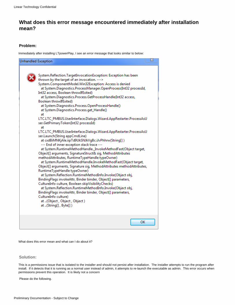
Linear Technology Confidential
Preliminary Documentation - Subject to Change
What does this error message encountered immediately after installationmean?
Problem:
Immediately after installing LTpowerPlay, I see an error message that looks similar to below:
What does this error mean and what can I do about it?
Solution:
This is a permissions issue that is isolated to the installer and should not persist after installation. The installer attempts to run the program afterinstall. If it detects that it is running as a normal user instead of admin, it attempts to re-launch the executable as admin. This error occurs whenpermissions prevent this operation. It is likely not a concern
Please do the following.

Linear Technology Confidential
Preliminary Documentation - Subject to Change
Close all error dialogsRelaunch LTpowerPlay from the normal desktop or start menu shortcut
If the above does not resolve the issue, please see to adjust application compatibility settings.http://ltpowerplay.com/help/uac/

Linear Technology Confidential
Preliminary Documentation - Subject to Change
Can I use LTpowerPlay to compare two project (.proj) files?Yes. Let's take an example where you wish to compare an original project file a.proj (the reference) against another project file b.proj that mayhave changes relative to a.proj.
Follow this procedure:
On the menu, select 'File > Open...' browse to a.projOn the menu, select 'File > Verify Configuration against Project File...' browse to b.proj
NOTE: The .proj files MUST have the same system tree (device addresses) for this to work.
LTpowerPlay will run a VERIFY procedure comparing a against b. Any differences will show up just as though you were comparing a.proj againsthardware that contains the values in b.proj.
Let's say that you took project file a.proj and modified device U2:7's VOUT_COMMAND (and related registers) from 3.3V (in a.proj) to 3.33V andsaved the modified project as b.proj. If you ran the above procedure, you would see VERIFY errors as shown below:
The values on hte left (in white) show the original values from a.proj. The values on the right show the values from b.proj that differ. If the filesare instead identical, a dialog will pop up that states there were no verification errors.

Linear Technology Confidential
Preliminary Documentation - Subject to Change
How do I update LTpowerPlay on a machine without internet access?You can always find the latest public version here:
http://ltpowerplay.com/updates/vin0/latest-version.php
This page will display a link to the latest .msi installer. Follow these steps to update:
Download the .msi installer provided in the above linkTransfer the .msi to the machine without internet access (using a USB drive or similar)Run the .msi on a machine that has an earlier version of LTpowerPlay installedThe .msi will automatically installs over and upgrade an older version of LTpowerPlay

Linear Technology Confidential
Preliminary Documentation - Subject to Change
Can I use my .license file on another computer?No. Licenses are "node locked" to a single physical machine. This means that if you attempt to use the .license file generated for one computeronto another computer, LTpowerPlay will reject the license file and ask you to apply for a new one. This is an easy and automated process. Justfollow the instructions to request a new license for your new computer, and the license file will be sent to you automatically
NOTE: If you perform major upgrades to the same physical machine (OS upgrade or perhaps major hardware upgrade), the hardware id maychange, invalidating the old license file. If this occurs, LTpowerPlay will reject the old license and prompt you to fill in information to request a newone. Again, this process is automated so it should be pretty easy to get a new license after a machine upgrade.

Linear Technology Confidential
Preliminary Documentation - Subject to Change
1. a. b.
2. a. b. c.
What does this error message, seen immediately after launching LTpowerPlaymean?Under certain circumstances, you may see an error similar to the one shown below immediately after attempting to launch LTpowerPlay:
This error may be associated with one of two issues:
The LTpowerPlay executable may not have been launched with sufficient permissions to generate the application.log file. See for instructions on how to resolve this issuehttp://ltpowerplay.com/help/uac/If this does not resolve the issue, check that you have permissions to modify the file (in this case application.log), and resolve thepermissions issue.
You may have multiple instances of LTpowerPlay running at the same time, preventing one instance from accessing the log fileLaunch the Task ManagerSelect the "Processes" tabFind all instances of LTpowerPlay.Shell.exe and select "Kill Process"
After resolving the issue with the appropriate method above, you should be able to launch LTpowerPlay successfully without error.

Linear Technology Confidential
Preliminary Documentation - Subject to Change
How to I use LTpowerPlay to 'burn in' settings permanently into EEPROMThe various devices that LTpowerPlay supports may contain hardware/RAM and EEPROM. Please note that all operations that transfer data aremanual operations driven by clicking a toolbar button. One exception is the telemetry loop which runs constantly polling telemetry RAM anddisplaying values in LTpowerPlay when the user is online with hardware.
The below graphic depicts the LTpowerPlay Communication/Memory Model, and explains how settings are transferred between the GUI andHardware/RAM, and also between Hardware/RAM and non-volatile-memory (NVM):

Linear Technology Confidential
Preliminary Documentation - Subject to Change
Is there a simple way to read, decode and save all the fault logs on my board atone time?Yes. It's called the System Snapshot tool. This tool provides a single-click method of storing all fault logs on the board into a single archive (.zipfile). It's available on the menu (under View > Windows) and in the Fault Log Window. Follow the short procedure below to save all the faultlogs:
Launch LTpowerPlayLoad your project (.proj) fileGo Online
If the Fault Log button looks like this , there are no fault logs present in the system, and no further action is necessary
If it looks like this , there are one or more chips in the system that contain non volatile fault logs. Continue.Click the Fault Log buttonIf you have not already, select one of the chips in the system tree on the left-hand side of the GUIIf the selected chip has a fault log, the EEPROM Log Status will indicate "LOCKED" as shown below:
Though you could read each individual fault log in the system one by one manually, there is a much faster way to save all fault logs to a.zip file:
Click the 'Export All...' button
This opens the System Snapshot tool and automatically saves a 'snapshot' (a .zip archive with one .rtf file per fault log)
The list of snapshots are shown on the right. If you want to explore the snapshot in windows explorer, select thesnapshot and click "Explore Snapshot"

Linear Technology Confidential
Preliminary Documentation - Subject to Change
This opens a windows explorer window that points to the selected .zip file within the snapshot folder:
The fault_logs subfolder of the zip file contains one .rtf (rich text file) per fault log on the board. In this specific caseshown below, there was only one fault log for the device U1, a LTC2974 at 7-bit I2C address 7'h32:
If you want to see all the snapshot .zip files, click the 'Up' icon in windows explorer to navigate out of the .zip file (click'Up' until you are at the the 'System Snapshots' folder):
At the System Snapshots folder level, you can see all the the .zip files, and copy/move them to other locations if you likefor archival purposes

Linear Technology Confidential
Preliminary Documentation - Subject to Change
My Views are Messed up. How can I recover to the default view configuration?Usually selecting 'View > Restore Default Layout...' on the LTpowerPlay menu will restore the views to their default layout:
However, in some rare circumstances, a recent change to the views may be causing a causing a crash in LTpowerPlay. When you restartLTpowerPlay, it will attempt to restore the old view layout, and if the crash persists, you may be in an infinite loop of restart app/crash. Thesesettings are persisted in a file in your file system under your user's 'AppData' folder. Follow the procedure below to delete these files and restorethe views to their default state:
Close any running copies of LTpowerPlayOpen a Windows Explorer WindowNavigate to c:\Users\<your user name>\Select the location bar at the top of the window that now contains "C:\Users\<your username>", and manually type in the 'AppData'subfolder (which is hidden by default)
For example, "C:\Users\mholloway\AppData"Navigate to the subfolder Roaming\LTC\LTpowerPlay underneath the AppDatata Folder. It will look like this:Delete the two .config files.
If you also wish to default all preferences, you can delete all files in this folder.
Re-launch LTpowerPlay
LTpowerPlay should start up with the default view layouts

Linear Technology Confidential
Preliminary Documentation - Subject to Change
I see LTpowerPlay in the taskbar, but I cannot see the window. How do I viewthe window?There are certain situations where the LTpowerPlay window may appear in the task bar, but you cannot see the window on your desktop. This isbecause LTpowerPlay attempts to restore the last position when it is launches. For instance, if the last time you launched LTpowerPlay you had amultiple monitor setup, and you have subsequently switched to a single monitor configuration, the saved position of LTpowerPlay may put theLTpowerPlay window out of the visible area of your desktop.
A simple workaround should restore LTpowerPlay to a visible area on your desktop. The following annotated images shows these steps:
Hover the mouse over the LTpowerPlay icon in the task barMove the mouse over the LTpowerPlay 'thumbnail' image that pops up, and right-click the mouse on the imageSelect 'Restore' in the context menu

Linear Technology Confidential
Preliminary Documentation - Subject to Change
How do I Clear Individual Items In LTpowerplay?It's easy to clear individual items like Fault Registers, Peaks, Energy meter accumulation, etc in LTpowerPlay. Consult the IC datasheet for whichregisters are individually clear-able. To clear a register that is clearable, please follow these steps:
Select the register of interest in the Telemetry/Status PanelClick the Right button on your mouseSelect 'Clear HW Register X' in the Menu, where X is the name of the Register you have selected
NOTE: If the register is not clearable, this item will not be available.
Example Screenshots:

Linear Technology Confidential
Preliminary Documentation - Subject to Change
Is There an Easy Way to Review Large ConfigurationsThere is a feature called 'settings review mode' which allows you to quickly visualize setting differences across larger systems using the 'All Pagesin System' view. Here's how to use it:
In LTpowerPlay, select 'View > Preferences' in the menuSet the Preference titled 'Enable Settings Review Mode' to 'True':
Select a desired configuration registerLook to the 'All Pages in System' View. It should look something like this:
The contents of the display will depend on the selected register. Items configured with the same settings are colored identically. This allows youto quickly visualize settings differences. In the example above, there are two unique values for TON_RISE (8ms and 10ms)

Linear Technology Confidential
Preliminary Documentation - Subject to Change
I have a Register Command Code. Can LTpowerPlay tell me the CorrespondingRegister Name?Yes, if the register is visible in one of the LTpowerPlay register views. Follow these steps:
Select a device in the tree that is the same device type as yoursAt the top of the 'Config' tab, type the hex value into the 'Lookup' box. Example below:
(i.e. type '0x21 <enter>'), LTpowerPlay will attempt to find the register that corresponds to this command code. If found, it will highlight the register in theConfiguration or Telemetry/Status View, and if a Configuration register, will also select the register's primary configuraiton group('Voltage' in this case). Here is the Result for the above Example:

Linear Technology Confidential
Preliminary Documentation - Subject to Change
How Can I Quickly Search for a Register by Name?If you know the beginning characters of the Register Name, you can type it into the 'Lookup' box at the top of the Config tab. LTpowerPlay willincrementally search for Registers that start with the characters you type, and will present a list of potential matches. You can select one of theseto navigate to it.
Example:
Select your device in the system treeAt the top of the 'Config' tab, type 'MFR_' into the Lookup box.
LTpowerPlay will attempt to find the registers that begin with the letters 'READ', and will present a list of corresponding matches. Selectthe Individual Register you want.When an item is selected, LTpowerPlay will highlight the register in the Configuration or Telemetry/Status View, and if a Configurationregister, will also select the register's primary configuration group/tab.

Linear Technology Confidential
Preliminary Documentation - Subject to Change
How can a project file be used to program devices in a systemHow can a project file be used to program devices in a system
Programming devices in a system is called In System Programming. LTpowerPlay supports In System Programming through a ProgrammingUtility.
How to Program
Invoke the Programming Utility menu:
After the Programming Utility Menu is invoked, there is an entry for a LTpowerPlay project file:
After entering a path or using the browser (... button), press "Program and Verify System" to program all devices in the project. Pressing "VerifySystem" will use the project file to verify the programming is correct.
The programming process will update the USER_DATA register with a Checksum of the data.

Linear Technology Confidential
Preliminary Documentation - Subject to Change
1. 2. 3.
Other Methods of Programming
Devices can also be programmed before soldering to a board using OEM files. See for more information on programming methods.AN145
Programming Devices with CRC failures in the NVM/EEPROM
If a device has CRC errors, the Programming Utility still able to program it. The utility will use the 0x5B global address to set the base address,cause the device/s to read their ASEL pins, and then program them.
Prerequsites
For any method of In System Programming to work, the following must be true:
All devices on the bus must share a common base addressAll devices on the bus must have unique ASEL configurationsThe LTpowerPlay project must contain the base address and the proper effective addresses (Base combined with ASEL)

Linear Technology Confidential
Preliminary Documentation - Subject to Change
1.
2.
How Can I Stop LTpowerPlay's Polling Loop, or make the Dongle's SCL/SDALines HiZThere are two methods you can use to instruct LTpowerPlay to stop using the I2C bus to poll telemetry/status of the devices in the system tree:
Click the 'Go Offline' Button in the toolbar at the top of the LTpowerPlay main window
Click the 'Stop' Icon in the telemetry plot
Both methods will insure that the dongle/host controller will leave the I2C SCL/SDA lines Hi-Z.
NOTE: With method 2, you can still 'manually' take action on the bus by clicking one of the toolbar icons (i.e. Write/Read All, etc), or byindividually writing/reading registers (F12/F11), but LTpowerPlay will remain Hi-Z on the bus until explicit user action is taken that requires I2C busaccess. Method 1 simply takes LTpowerPlay 'offline' so these I2C functions are no longer available until you go online again.

Linear Technology Confidential
Preliminary Documentation - Subject to Change
Can LTpowerPlay be run Without Administrative Priviliges, or Under aNon-admin Account?In some restricted environments (secure networks, etc), users may not be able to run programs with administrative privileges. Until very recently,admin privileges were required to install and run LTpowerPlay. This was done for simplicity, as running without admin privileges would rendersome functions void (like automatic updates). In the future, an update will be available that will allow LTpowerPlay to be run under a 'normal user'account (without admin privilege).
If you are running a version greater than 1.2.9.0 of LTpowerPlay, your version is already able to run without admin privileges. Otherwise, you canload the beta version of the software that does not require admin here:
BETA Version that does not require admin privilege:
http://ltpowerplay.com/updates/vin0/1.2.10.0/SetupLTpowerPlay.msi

Linear Technology Confidential
Preliminary Documentation - Subject to Change
Can I call LTpowerPlay from a batch file to program devices in-system?Yes. As discussed earlier, this may be appropriate in situations where you want to use LTpowerPlay and the DC1613A dongle to programdevices in system, but you do not want to use the GUI interactively. Other possibilities were discussed in other items, but this specificexample illustrates how to call the LTpowerPlay executable from a DOS batch program, and check the return code for success or failure.
Open NOTEPAD and create a batch file called program.bat file with the following contents:
@ECHO OFFREM Attempt In System Device Programming"c:\Program Files (x86)\Linear Technology\LTpowerPlay\LTpowerPlay.Shell.exe" -Program-Verify -ProjectFile="c:\my.proj" >detail.logREM Check Return Status for ErrorsIF %ERRORLEVEL% NEQ 0 ( ECHO "ERROR Programming. Detailed Log Follows:" TYPE detail.log GOTO END)ECHO "SUCESSFULLY PROGRAMMED!":ENDPAUSE
Substitute your .proj file for "c:\my.proj"Open a DOS command prompt (start, run, 'cmd.exe')Change directories to the location of the program.bat file you createdtype 'program.bat'
In the case of success, the following output will be printed:
C:\>program.bat"SUCESSFULLY PROGRAMMED!"Press any key to continue . . .
In the case of failure, the output stored in detail.log is echoed to the output as shown below:
program.bat contents
Example Output for Success

Linear Technology Confidential
Preliminary Documentation - Subject to Change
C:\Users\mholloway\Desktop>program.bat"ERROR Programming. Detailed Log Follows:"
LTpowerPlay.Shell.exe version 2.0.0.0Copyright (c) Linear TechnologyProcessing project file c:\my.projExporting temporary ict in system programming hex file 'c:\my.ict'Processing in system programming (.ict) hex file 'c:\my.ict'...
[2/23/2016 13:15:19.945] Checking for USB Host Controller...[2/23/2016 13:15:20.035] Processing Programming and Verification Algorithm[2/23/2016 13:15:20.042] Length=6,Type=24,EventValue=0 Event='BEFORE_BEGIN'[2/23/2016 13:15:20.042] Length=6,Type=24,EventValue=0[2/23/2016 13:15:20.044]Length=8,Type=27,MetaDataType=0x01,MetaDataLength=2,0x0000 Meta DataType='SERIAL_NUMBER_HOLDER'[2/23/2016 13:15:20.044] Skipping Serialization[2/23/2016 13:15:20.044] Length=6,Type=24,EventValue=16Event='BEFORE_INSYSTEM_PROGRAMMING_BEGIN'[2/23/2016 13:15:20.044] Length=6,Type=24,EventValue=16[2/23/2016 13:15:20.044] Length=9,Type=16,PMBusWriteWord(0x05B,0x10,0xC000)[2/23/2016 13:15:20.055] !!!!!!ERROR: Device at address 0x5B NACKED WriteWordtransaction CMD=0x10, DATA=0xC000
Error Programming and Verifying Device! See Programming Log for details.Press any key to continue . . .
This is one example of how to call LTpowerPlay from the command-line and inspect the return value for errors. Many other possibilities exist. This is meant as an illustrative example.
Example Output for Failure

Linear Technology Confidential
Preliminary Documentation - Subject to Change
When I click 'Add default LTCXXXX Chip', why do the settings not match thedatasheet/factory defaults?In general, the factory/datasheet defaults for a chip, though aimed at ensuring safety when placed into target circuit, may not provide asimple/easy starting point for building configurations for board bring up. The GUI defaults for chips are aimed at making it easy for you to build aconfiguration for a final configuration.
An example will illustrate the difference:
The factory Default value for ON_OFF_CONFIG for LTC2978 is 0x12. This setting causes the chip to ignore both the OPERATION and theCONTROL pin, so that the output will never power up. While this may be helpful to you if you load a factory default part onto your board, toensure safety, it creates unnecessary work for you to get your board rails up if you are building a configuration in LTpowerPlay. The GUI defaultfor the same register is 0x1E, which tells the chip to require both CONTROL pin and OPERATION command to enable the output. TheOPERATION command is defaulted to Off, so that the chip will still remain safely off until you decide to turn it on, but when you program theOPERATION command to On, the chip will turn on as expected. With the datasheet default setting of 0x12, turning the rail on would require extrasteps, and create confusion.
Because of this, the GUI defaults may not match the datasheet defaults for a given part. The GUI defaults are chosen as a balance of safety andsimplicity to help you build a configuration for your final application quickly.
NOTE: You can find the datasheet defaults in the command table of the datasheet for the part. Press F1 in LTpowerPlay to bring up thisdocument. You may also find the datasheet defaults .proj file under the project_files folder of the installation folder of LTpowerPlay.

Linear Technology Confidential
Preliminary Documentation - Subject to Change
How do I get more information on the status/fault indicator XXXX?The last section of this FAQ document contains detailed information for various fault types. Starting from the table of contents of the FAQdocument, navigate to the last section of the table of contents (titled "What's this Fault?"). Find the table of contents entry for the fault type ofinterest, and click its hyperlink to navigate to the detailed entry.
The "What's this Fault" entries contain a number of useful information including:
A description of the faultWhere relevant, an example reference waveformDiscussion of how the part responds to the conditionCommon causes of the conditionRemedies and WorkaroundsTroubleshooting tips, including scope debug tips where relevant
The detailed information is available 'in situ' while using LTpowerPlay, in a new tool called the "What's this Fault tool". This tool is similar to the"Why am I Off tool" in two ways:
It sits at the periphery of the main LTpowerPlay windowIt continuously analyzes status for the selected channel and provides context specific help for that channel
Use the following procedure to get detailed help for status/fault information on the selected channel within LTpowerPlay:
Select the channel of interest in the system tree on the left side of LTpowerPlay:
Move your mouse to the right side of the main LTpowerPlay window and hover over the tab titled "WTF" (What's this Fault):
The "What's this Fault tool' will fly out and you can inspect the detailed help as shown below (example shown is a TON_MAX_FAULT):

Linear Technology Confidential
Preliminary Documentation - Subject to Change
If the channels contains more than one fault/status, the first one is selected in the list. You can select other statuses to show detailedinformation for the item of interest

Linear Technology Confidential
Preliminary Documentation - Subject to Change

Linear Technology Confidential
Preliminary Documentation - Subject to Change
1.
2.
LTpowerPlay requires .NET Framework v2.0, and my computer does not havethis version. How do I get it?Note that the .NET Framework 3.5 also contains version 2.0, so installing version 3.5 will also install version 2.0. Until recently, the .NETFramework 2.0/3.5 was automatically installed with the operating system. Newer versions of Windows (>= Windows 8) have the option to install.NET Framework 3.5 from the control panel, but it is not installed by default. You can manually install .NET 3.5 as follows:
Method 1: Enable the .NET Framework 3.5 in Control Panel
You can enable the .NET Framework 3.5 through the Windows Control Panel. This option requires an Internet connection.
Press the Windows key Windows on your keyboard, type "Windows Features", and press Enter. The Turn Windows featuresdialog box appears.on or off
Select the check box, select OK, and reboot your computer if prompted..NET Framework 3.5 (includes .NET 2.0 and 3.0)
Method 2: Manually download and install the .NET Framework 3.5
If the above method is not available or working, you can download and install the .NET Framework 3.5 using the following link:
https://www.microsoft.com/en-us/download/details.aspx?id=251504

Linear Technology Confidential
Preliminary Documentation - Subject to Change
Can LTpowerPlay dump the contents of a device's EEPROM to a file?Yes. LTpowerPlay has a command-line option that takes both a target device address and the location of a text file to write. If you wish to dothis, follow these steps:
Close any running instances of LTpowerPlayOpen a Command Prompt (preferably as administrator)
Click <start>Type: cmd
Right click the command prompt shortcut and select 'Run as Administrator'change directories to the LTpowerPlay installation folder (C:\Program Files (x86)\Linear Technology\LTpowerPlay by default):
Type: cd "C:\Program Files (x86)\Linear Technology\LTpowerPlay"Run the program with the -t (your target adress) and -d (your dump file) options:
(Example) C:\Program Files (x86)\Linear Technology\LTpowerPlay>LTpowerPlay.Shell.exe -t=0x5c -d=c:\mydump1.txtReplace "0x5C" above with the target address of the device from which you wish to read the EEPROMReplace "c:\mydump1.txt" above with the location of the output file you wish to write
Running LTpowerPlay with this command-line option will read the EEPROM of the device at the specified address (0x5C in this example) directlyand store the data into the specified text file (c:\mydump1.txt in this example).
NOTE: Please insure that the account running the command prompt has sufficient write access to create the file. If not, substitute an appropriatefile location, or run the command prompt as administrator as described above.
An example file fragment is shown below for your information:
Dump of data at chip address 0x5CNVM Data...Packing Code=0x7701NVM DATA Length= 512 bytes (0x0200)Word #0 (0x0000) = 0x7D96Word #1 (0x0001) = 0x3F20Word #2 (0x0002) = 0x0063Word #3 (0x0003) = 0x00FF
Example output file

Linear Technology Confidential
Preliminary Documentation - Subject to Change
What is the syntax of scripts (command-files) in the I2C Utility?The format of command-files is .csv. There are 3 types of lines: Commands, comments, and special instructions. Command lines tell the scriptinterpreter to issue some I2C/SMBus transaction (write or read) and for reads, optionally check the return value. A command instruction must beformatted as follows:
<addr>,<protocol>,<cmd>,<data>,<mask>
The first 2 fields are always required. A line should always have 4 commas. When fields are not used, keep the commas as shown in theexample at the end.
Comments start with #. These lines are ignored functionally, except that the line is printed in the output log for convenience. Commas are alsoallowed after the last field if you place a '#' character there.
Special instructions start with #! and presently include the #!Sleep command. Sleep takes the value of the delay in ms.
A description of the command line fields follows:
<addr> (always required): the 7-bit address of the device (same as what is shown in the LTpowerPlay system tree)NOTE: All PSM devices respond to the special address 0x5B
<protocol> (always requried): Must be one of the following:WB: SMBus write byte protocolRB: SMBus read byte protocol. Print read value.
Optionally test read value against expected value and optional maskWW: SMBus write word protocol (low byte sent first)RW: SMBus write word protocol (low byte read first). Print read value.
Optionally test read value against expected value (if present in <data>) and optional mask (if present in <mask>).SB: SMBus send byte protocol (command with no data, like STORE_USER_ALL for instance)MB: Read/Modify/Write a byte command using read/write byte protocols
Read value at specified <cmd> using SMBus read-byte protocolModify bits that are ones in <mask> to equal the value provided in <data>Write modified value to specified <cmd> using SMBus write-byte protocol
MW: Read/Modify/Write a word command using read/write word protocols and a maskRead value at specified <cmd> using SMBus read-word protocolModify bits that are ones in <mask> to equal the value provided in <data>Write modified value to specified <cmd> using SMBus write-word protocol
RCVB: SMBus receive byte protocol (address with no command, like SMBus ARA for instance)Enter 0x00 for <cmd> even though the field is not used. The software requires <cmd> to be be non-nullNOTE: <data> and <mask> fields can also be applied to the received byte (see example ARA check in below script)
<cmd> (always required): the 8-bit sub-address or command code to write/read (i.e. 0x01 for PMBus OPERATION command)
<data> (required for writes/modify, optional for reads) hex value of the dataFor write protocols (WW, WB) this is just the data value to writeFor read protocols (RB, RW) , if this field is present the actual value read from hardware will be tested against this expectedvalue, and fail the script if not equal
NOTE: If <mask> is provided, only the bits in the mask are tested against the <data> value provide<mask> (required for modify, optional for reads) A mask indicating the bits of concern for modification or testing of read values
For read protocols (RB, RW), if this field is present the actual value read from hardware will masked with the <mask> value andthen tested against a pre-masked <data> value. The script will fail if not the <data> and masked read values are not equal.For modify protocols (MB,MW), this field must be present. The mask indicates which bits should be modified after reading beforewriting back to hardware.
Example Script:
NOTE: The example uses device address 0x30

Linear Technology Confidential
Preliminary Documentation - Subject to Change
#Write the PAGE register (command 0x00) to 0xFF (all pages)0x30,WB,0x00,0xFF,#Write the OPERATION register (command 0x01) to ON (0x40) – sequence all channels off0x30,WB,0x01,0x40,
#Wait 1 second#!Sleep 1000
#Write the OPERATION register (command 0x01) to ON (0x80) – turn all channels on0x30,WB,0x01,0x80,
#Wait 1 second#!Sleep 1000
#Check device channel 0 – set PAGE to 00x30,WB,0x00,0x00,#Check that the device is ON. That is, that bit 6 of STATUS_BYTE (command 0x78) is azero. Fail the script otherwise.0x30,RB,0x78,0x00,0x80#Check that STATUS_VOUT (command code 0x8b) is 0x0000. That is, there are no voltagerelated faults or warnings0x30,RB,0x7A,0x00,0x80
#Check device channel 1– set PAGE to 10x30,WB,0x00,0x01,#Check that the device is ON. That is, that bit 6 of STATUS_BYTE (command 0x78) is azero. Fail the script otherwise.0x30,RB,0x78,0x00,0x80#Check that STATUS_VOUT (command code 0x8b) is 0x0000. That is, there are no voltagerelated faults or warnings0x30,RB,0x7A,0x00,0x80
#Issue CLEAR_FAULTS (command code 0x03) send byte protocol0x30,SB,0x03,,
#Wait 1 second#!Sleep 1000
#Read ARA and assert that the value is 0xFF (no devices holding ALERTB low on the bus)0x0C,RCVB,0x00,0xFF,0xFF
Example Script

Linear Technology Confidential
Preliminary Documentation - Subject to Change
Device Programming FAQThis Section contains Frequently Asked Questions about Device Programming

Linear Technology Confidential
Preliminary Documentation - Subject to Change
Can I program my PMBus Device over JTAG?To be able to program your PMBus device via JTAG, what needs to happen is that you either use a device on the bus with boundary scanJTAGaccessible pins connected to the PMBus, or you use an external device (Asset Intertech provides one, shown as #4 in the second picture) whichconnects into your normal chain and provides a device with some IO that can be connected to the PMBus. JTAG
In the second image, we are programming a powerstick via . Since there are no devices on the powerstick that accept , we need thatJTAG JTAGScanLite board that does the to bit-banged PMBus conversion. (#4)JTAG
On a customer board that already has devices, it is presumable that one of those devices is already connected to the PMBus. ForJTAG JTAGinstance if they are programming an FPGA or something which also is on the bus to communicate with the PSM devices, then all you need is totalk to the same FPGA. There would be part of the process that would actually program the FPGA, the other part would be manipulating theJTAGboundary scan nodes on the PMBus lines of the FPGA to wiggle high/low and bit-bang full PMBus.
The only real caveat is bus speed. As per PMBus, we need to keep the bus speed above 10KHz, and we like to keep it well above that. Since weare bit banging, every PMBus clock takes 2 full chain trips. This basically means that for large chains with thousands of nodes, youJTAG JTAGwill need to keep the clock high enough to allow for a fast enough PMBus clock.JTAG

Linear Technology Confidential
Preliminary Documentation - Subject to Change

Linear Technology Confidential
Preliminary Documentation - Subject to Change
Does BPM (or Arrow) Support my LTC device for programming?As a general rule of thumb, we strive to enable programming support for every LTC device that could need it before it is released for sale. But tocheck the public status of any part, visit this external link to BPM's "Find-Your-Device" page and query for supported devices
http://www.bpmmicro.com/find-your-device/
For example, as of December 2014 the current list is as follows:
Manufacturer Package
Linear Technology LTC2936IGN#TRPBF SSOP(24)
Linear Technology LTC3882EUJ QFN(40)
Linear Technology LTC3883IUH#TRPBF QFN(32)
Linear Technology LTC2933CDHD#TRPBF DFN(16)
Linear Technology LTC3882EUJ#PBF QFN(40)
Linear Technology LTC3883EUH#TRPBF QFN(32)
Linear Technology LTC3882IUJ QFN(40)
Linear Technology LTC3883EUH-1#TRPBF QFN(32)
Linear Technology LTC2936IGN#PBF SSOP(24)
Linear Technology LTC3882 QFN(40)
Linear Technology LTC2933CGN#TRPBF SSOP(16)
Linear Technology LTM2988IY#PBF BGA(144)
Linear Technology LTC2977IUP#PBF QFN(64)
Linear Technology LTM4676 (BGA144) BGA(144)
Linear Technology LTM2988CY#PBF BGA(144)
Linear Technology LTM2987CY#PBF BGA(144)
Linear Technology LTM2987IY#PBF BGA(144)
Linear Technology LTC3882IUJ#PBF QFN(40)
Linear Technology LTC3883IUH-1#PBF QFN(32)
Linear Technology LTC3880IUJ QFN(40)
Linear Technology LTC2977CUP#PBF QFN(64)
Linear Technology LTC2933CDHD#PBF DFN(16)
Linear Technology LTC2933IDHD#PBF DFN(16)
Linear Technology LTC3880EUJ-1 QFN(40)
Linear Technology LTC2937 QFN(28)
Linear Technology LTC2933IDHD#TRPBF DFN(16)
Linear Technology LTC3880IUJPBF QFN(40)
Linear Technology LTM4676 LGA(144)
Linear Technology LTC3883IUH#PBF QFN(32)
Linear Technology LTC3883EUH-1#PBF QFN(32)

Linear Technology Confidential
Preliminary Documentation - Subject to Change
Linear Technology LTC3880EUJ#PBF QFN(40)
Linear Technology LTC2933CGN#PBF SSOP(16)
Linear Technology LTC2974CUP#TRPBF QFN(64)
Linear Technology LTC3883EUH#PBF QFN(32)
Linear Technology LTC2974CUP#PBF QFN(64)
Linear Technology LTC2936CGN#PBF SSOP(24)
Linear Technology LTC2974IUP#PBF QFN(64)
Linear Technology LTC2974IUP#TRPBF QFN(64)
Linear Technology LTC3880IUJ-1 QFN(40)
Linear Technology LTC2933IGN#TRPBF SSOP(16)
Linear Technology LTC3880EUJPBF QFN(40)
Linear Technology LTC2933IGN#PBF SSOP(16)
Linear Technology LTC2936CGN#TRPBF SSOP(24)
Linear Technology LTC3883IUH-1#TRPBF QFN(32)
Linear Technology LTC3880IUJ#PBF QFN(40)
Linear Technology LTC3880EUJ QFN(40)
Linear Technology LTC2978ACUP#PBF QFN(64)
Linear Technology LTC2978IUP#PBF QFN(64)
Linear Technology LTC3880EUJ-1#PBF QFN(40)
Linear Technology LTC2978AIUP#PBF QFN(64)
Linear Technology LTC3880IUJ-1#PBF QFN(40)
Linear Technology LTC2978CUP#PBF QFN(64)

Linear Technology Confidential
Preliminary Documentation - Subject to Change
How do I export the correct programming files from LTpowerPlay?Which type of file you export depends on how you plan to program devices.
Load your project file into LTpowerPlaySelect the
A: Order pre-Programmed parts from LTindividuallyB: Order pre-programmed parts from, Arrow or a Contract Manufacturer (CM)individuallyC: Program all the parts on your own board 'in system' via I2C**
Depending on the choice above, select the appropriate menu pick (marked A, B, or C) in the File menu of LTpowerPlay as indicatedbelow:
Depending on your choice above, different file formats will be generated:
Option A: LTpowerPlay generates a .zip file for your entire board (including programming files for each individual device in the .proj file)with multiple programming file formats within the .zip file. You need to upload this entire file to the Linear Express website as instructedby the programming wizard that launches when you select this option. The Linear Express server will parse the .zip file and allow you tochoose one or more devices and easily order the programmed parts.Option B: LTpowerPlay generates a .zip file that contains one .OEM file for each device in the .proj file, as well as the original source .projfile. This is useful for archival purposes.
However, when you will send the individual .oem files to the programming house. One .oem file is stored per device in theproject file. The files are stored in unique folders within the zip that are named and distinguished by device type, address, and Unumber for your convenience. Within the appropriate subfolder is the corresponding .oem file for that device. The .oem file isnamed to include the unique configuration CRC. Read the file ProgrammingInstructions.txt in the .zip file for more information onwhere the individual .oem files are stored within the .zip file.Some customers prefer to have one file per device. This can be easily achieved by extracting the .zip file and then accessing theindividual .oem files within the archive. The folder names will help you keep things straight. In the event you do this, it is stillstrongly recommended that you archive the generated .zip file which also contains the original .proj file that was used to generateall the programming files.
Option C: LTpowerPlay generates a single .isp (in system programming file) that is capable of programming all the devices on your board'in system' via I2C.**
**NOTE: Option C requires you to implement custom software to process the .isp (in system programming) file, validate and test your software,etc, which may require significant engineering investment on your part. Contact LT factory for more information.

Linear Technology Confidential
Preliminary Documentation - Subject to Change
How do I hook-up a dongle to my customer board?The DC1613 "dongle" provides connectivity between a personal computer and an I2C bus connected to various Linear Technology solutions. Thedongle connects to the PC through an isolated USB bus that provides a serial port and some limited power. The PC talks to the I2C bus throughthis serial port, and can use LTpowerPlay to control and visualize the operations of the LTC parts. The dongle connects to power and datathrough a 12-pin ribbon cable, with connections for the I2C bus, and for power and ground. Many LTC PSM demo boards have a 12-pin connectorthat accepts this 12-pin ribbon cable. Custom boards should include connections for the dongle, and can either include the 12-bin connector, or aminimal 4-pin connection.
The recommended part number for the 12-pin connector is: FCI, 98414-G06-12ULF
The 12-pin ribbon cable connector part number is: FCI, 90311-012LF
Alternatively, the 4-pin connector part number is: TE CONNECTIVITY 5-104071-7
The connectors are keyed to prevent inserting the connector incorrectly.
There are four required pins (the others are optional):
NAME NUMBER FUNCTION
SDA 2 I2C Data
SCL 4 I2C Clock
GND 3 Ground
+3.3V 5 +3.3V Logic power (100mA max)
The 12-pin connector schematic symbol looks like this:

Linear Technology Confidential
Preliminary Documentation - Subject to Change
The 12-pin connector layout footprint (top view) looks like this:

Linear Technology Confidential
Preliminary Documentation - Subject to Change

Linear Technology Confidential
Preliminary Documentation - Subject to Change
How to Decode a Standard Intel Hex FileThe listing below shows an example Intel Hex file. The colour coding below the listing defines the various fields of the Intel hex file:
As you can see, each line of the hex file starts with a “:” character, followed by a byte count, address, record type, some number of data bytes,and ends with a checksum for that line. Each line of the file in this case is an ‘Intel Hex File Data Record’ (record type 0x00), with the exception ofthe last line, which is a standard Intel Hex File ‘end of file’ (EOF) indicator.
The ‘address’ field for each line refers to the starting byte address of the first byte of the line. As you can see in the example, the first 16 databytes are intended to be located starting at byte-address 0x0100. The next 16 data bytes (on the second row) are located starting at address0x0110. So this file defines what we would call a linear sequence of bytes.
LT Programming Hex Files will always represent a linear/contiguous sequence of raw bytes starting at byte address 0x0000 and going upward.
The In-System Programming software has completed the first step of processing this file when it has built a raw byte buffer by reading the rawbytes of the hex file.

Linear Technology Confidential
Preliminary Documentation - Subject to Change
How to power device In-Circuit without powering the entire system?By adding a PFET inline with the PSM devices' power inputs, you can keep the PSM products' brains alive even without powering the wholesystem.This is very useful for debugging where you might want the rails to turn off but to continue to monitor the large amount of useful telemetrydata and fault logs available. The latched status regisrers won't get reset since the power is continuous making it easier to spot which actual faultsare present.
The circuit below recommends a DC2086A Power Programming Adapter to use inbetween the USB PMBus Controller (i.e. DC1613A). While thisis always recommended, you can sometimes connect your USB PMBus Controller directly to your board using a 12pin or 14pin cable (vs. 4pin,12pin, or 14pin on the DC2086A) as long as your total current draw is less than the absolute maximum of 100mA. The DC2086A supplies up to2.3A on the same power rails.

Linear Technology Confidential
Preliminary Documentation - Subject to Change
How Do I Program Controllers without VIN
How Do I Program Controllers without VIN?
The FAQ Entry describes how to power the logic of Controllers and ManagersHow to power device In-Circuit without powering the entire system?without VIN. This allows you to communicate over PMBus to the device without board main power. This is a safe state for programming devicesbecause power stages will not be powered.
In the Controller case, the Controller will not be fully reset. Even though the PMBus is active, LTpowerPlay and/or your system controller cannotcommunicate with the device using its expected address. This is because the device has not read the ASEL pins, nor the device read itsMFR_ADDRESS register from its EEPROM. A controller will only read and apply the address information if VIN is applied.
There is a way to force the Controller to read its MFR_ADDRESS and apply the ASEL pins, so that LTpowerPlay and/or your system controllercan communicate with the device.
Manually Forcing the Address
Under the Custom Scripts menu of LTpowerPlay, select the power_LTC3880s_with_no_VIN.txt item.
After this script runs, all Controllers on the bus will have their expected address.
After the Address is Fixed
Once the address is fixed, you can open a LTpowerPlay project that has matching addresses, or use the LTpowerPlay programming utility foundin the Utilities menu.

Linear Technology Confidential
Preliminary Documentation - Subject to Change
What's the difference between In-Flight Update (IFU) & In-Circuit Programming(ICP)?
In-Flight Update
Tested and Supported CodeThis is best for customers to implementContact Mike Jones for support
In-Circuit Programming
Example C code for learning purposes onlyThis is best for OEMs to implement (like BPM)Contact Nick Vergunst for support

Linear Technology Confidential
Preliminary Documentation - Subject to Change
1. 2. 3. 4.
What are the different CRC Options Available?
Overview
There are several CRCs used by PSM Controllers/Managers and tools to ensure reliability of operation an integrity of manufacturing processes.They are:
CRC within the device EEPROM to guarantee integrity of the device settingsCRC within a USER register to guarantee integrity of the programming processCRC of OEM files to guarantee integrity of the programming processCRC of SL configuration files to guarantee integrity of the programming process
Internal CRC (1)
The internal CRC are extra bytes stored in the device EEPROM that are calculated from EEPROM data. When the STORE_USER_ALLcommand is executed, the device calculates the CRC as part of the store process and places the CRC in the EEPROM. When a device ispowered on or reset, the device fetches data from the EEPROM and stores it in RAM. During transfer, the CRC is recalculated from the EEPROMdata and compared with the CRC also stored in EEPROM. If there is a mismatch, the device is not allowed to power on rails. The EEPROM hasto be re-written to enable device operation.
Bulk programming the device sends data directly to EEPROM using PMBus commands, and the CRC is externally calculated and sent with thedata. When the device is then power cycled or reset, the same comparison behavior described above takes place.
The purpose of this CRC is to ensure the device never operates with bad data.
Register CRC (2)
The register CRC is a value placed into a USER register by external tools. The device does not use this value in any way. The device can't usethis value because USER registers are just scratch pad registers for users. The fact that a CRC is placed in one of these is purely a practicalconvention.
When a device is programmed with one of the LTC tools/methods, a CRC is calculated using a subset command/register values. You can think ofthis as a signature of a particular device configuration. To work properly, any registers with dynamic contents, such as status or DAC values(servo), must not be part of the calculation. Essentially, this means the CRC covers the static settings of the device.
Because the device cannot use this value internally, if it is modified by firmware, the device will never know and will not change behavior. If anycommand/register values are changed, the device will act on them, but the inconsistency of the CRC will not affect the behavior of the device.
This means the CRC's value is limited to use by tools and engineers using LTpowerPlay (LTPP) or other means of reading data from the device.
From within LTPP, if you use the menu Utilities > Configuration/CRC, you will see a display like the above picture. This includes the CRC(checksum) value, and the location.
The following describes the algorithm for calculating the CRC (checksum)document
OEM CRC (3)
The OEM CRC is a calculation on OEM files as part of the OEM export system found in the LTPP File menu. App Note 145 Options 2A, 2B, 3A,and 4B are programming methods that use OEM files. An OEM file is a programming file for a single device, typically in a socket. In contrast, anISP file is a programming file for multiple devices, typically in a system.
You may want to know why these are different. In a socket, a device can be programmed using the global address 0x5B, and then the state of theaddress select pins does not matter. Furthermore, the device cannot power on, so the primary focus is on correct programming of a device. In asystem, the address 0x5B cannot be used for the programming because each device has different settings. Furthermore, it has to be programmedin a way that there are no dangerous side effects on the load, so the primary focus is on correct programming of a system. This can be confusingif you have looked at the OEM or ISP files, because their content has the same formatting. The data language that contains the data andprogramming instructions is common to both file types, but the content is different for each file type.

Linear Technology Confidential
Preliminary Documentation - Subject to Change
When OEM files are created for LTExpress, the CRC values are displayed in the LTPP GUI during the ordering process. When the OEM files areexported for other methods, a zip file is created. The CRC values are contained in the documents of the zip file.
Refer to for details on these CRCs and how they are documented and used.AN145
Now that you know how the value is created and used, you can leverage the CRC in your production environment in the following ways:
Firmware can confirm the valueManufacturing tools can confirm the valueEngineers using LTPP can confirm the value in the GUISocket programming processes can pull QA samples and confirm the value
In every case, this means confirmation of the signature put into the device by tools.
Note that when using the LTPP Programming utility, programming a device creates the same algorithm as an ISP file, and executes it, andtherefore the same CRC will be placed in the USER command.
Note that when using ISP files and firmware to program devices, it will place the same CRC in the USER command. This is because the CRC iscalculated by LTPP and placed in the ISP data.
Basically, this means that all methods that program devices using OEM, ISP files, or the LTPP Programming utility all result in a CRC in a USERcommand that is stored in EEPROM.
SL CRC (4)
SL devices are ones that have an LTC-assigned part number that you can order. This order is backed by an OEM file, that is used duringmanufacturing. To keep track of the OEM file / part number relationship, a CRC is used. This CRC is the same CRC generated when exporting anOEM file. The process used by LTExpress and SL are different, but both use the generated CRC to keep track of the files.

Linear Technology Confidential
Preliminary Documentation - Subject to Change
What if I need more than 100mA from the USB PMBus Controller (i.e.DC1613A)?In many cases the DC1613A or compatible USB PMBus Controller can be used directly with demo boards and customer boards that haveminimal components. For instance most of our demo boards have 1 device or a handful of devices that you want to power from the dongle. Butwhat happens if you are lucky enough to have the problem that you have so many components that you are overloading the dongle?
The answer lies in the DC2086A, the Powered Programming Adapter, which can supply up to 2.3A on the 3.3v power rail. A block diagram of theDC2086A is shown below.
Notes on the DC2086A:
4.5v to 18v DC Input (3 input power options)Beefed up 3.4v output up to 2.3ABeefed up 5.0v output up to 1.1AFull Isolation between input and outputProvides cable adaptation between 12pin and 14pin inputs to 12pin, 14pin, and a smaller footprint 4-pin headerUSB is Power Only NOT FOR DATA it is for power
Images of the DC2086A

Linear Technology Confidential
Preliminary Documentation - Subject to Change

Linear Technology Confidential
Preliminary Documentation - Subject to Change
What is the format of the LT Programming File?The LT Programming Hex File is a standard Intel 386 hex file, also known as I32HEX or INTEL 32 Hex file Format. For detailed information on theIntel hex format, pelase reference this Wikipedia article: .http://en.wikipedia.org/wiki/Intel_HEX
At the lowest level of interpretation, the LT Programming Hex file represents a simple linear sequence (or ‘array’) of raw bytes. Higher levelstructures are imposed on this sequence of bytes to define a set of what we call “LT Programming Records”.
Each of these LT Programming Records instructs the In-System Programming software to perform a particular operation. As an example, one LTProgramming Record type, PMBUS_WRITE_BYTE_NOPEC instructs the In-System Programming software to execute a PMBus/SMBus writebyte operation to a specified address with a specified command code and data byte.
Generally LT Programming Record ‘instructions’ are somewhat low level – that is, they do not burden the In-System Programming software withunderstanding the algorithm necessary to program a device – the In-System Programming software simply executes a series of simpleinstructions, and in the order they are defined in the LT Programming Hex File.
Once the In-System Programming software has successfully processed all the LT Programming Record ‘instructions’ it will have successfullyprogrammed and verified the NVM for all chips for a particular system as defined in the file.

Linear Technology Confidential
Preliminary Documentation - Subject to Change
What is the Programming Power Circuit?The Programming Power Circuit is referenced in many places and refers to a circuit capable of powering the LT devices independent of system orboard power. This is extremely useful for debugging and essential for in-circuit or in-system programming (ICP or ISP).
Please refer to " " for one such example circuit.How to power device In-Circuit without powering the entire system?

Linear Technology Confidential
Preliminary Documentation - Subject to Change
What options do I have for getting Programmed Devices?
Linear Technology Options
LTExpress & Linear Technology SL#
We offer programming options for all of our devices. By going with LTC, we can get you individual pre-programmed parts quickly as well as inmass. Because we program them ourselves, any fallout that may be experienced at other vendors is eliminated as we only ship you goodprogrammed and tested devices. We can do marking on the top of the package, labels, and quick turn orders. Contact sales for more information.
3rd Party Programming of LTC Devices
BPM
We plan on supporting BPM fully with all devices being available at or near RFS. We also have many more non-RFS devices in the queue beingprepared. To use this method, you must buy the hardware which includes your base programmer and a socket module specific to the device youwant to program. You then program via BPWin software
Supported: (13+) LTC2933, LTC2936, LTC2974, LTC2975, LTC2977, LTC2978, LTC2980, LTC3880, LTC3882, LTC3883, LTM2987,LTM2988, LTM4676
Arrow
Arrow uses BPM Hardware so all BPM supported devices are supported at Arrow at or near RFS. Arrow will program the devices withouthardware investment or software maintenance on your end.
Asset Intertech
Supports all In-Circuit Programming devices when properly connected to JTAG device. If no JTAG devices are available or connected to thePMBus, they support programming through a "ScanLite" Board.
JTAG Technologies
Supports all In-Circuit Programming devices when properly connected to JTAG device.
System General – ** NOTE NOT RECOMMENDED **
System General currently supports the LTC2974, LTC2978, and LTC3880. We do not plan on supporting them for any other devices. We haveonly verified and tested early programming methods with the 3 mentioned devices. As our algorithms change and improve periodically it is not aguaranteed statement that their programming will continue to work for all Linear Technology devices. We do not recommend using SystemGeneral as a solution. If you do use System General, you will have to buy the hardware (Socket Module & Base Programmer) or have themprogram your devices.

Linear Technology Confidential
Preliminary Documentation - Subject to Change
What Programming Option Should I choose?
Note 1: Details about the Programming Power Circuit can be found here: What is the Programming Power Circuit?

Linear Technology Confidential
Preliminary Documentation - Subject to Change
Where does LTpowerPlay store it's computed CRC in the part?LTpowerPlay computes a CRC that uniquely identifies the configuration and may store this into scratchpad EEPROM of your part. We call thisthe "LTpowerPlay Configuration Checksum", or unique configuration identifier. This CRC is used for a very specific purpose. Consult the FAQ onvarious CRC types used to understand other CRCs used.
This CRC, stored into the part, provides a convenient way to read the register (via firmware for instance) to identify the original configuration. ThisCRC will be stored into the project file and into generated programming files of all types, regardless of how you program your devices.
The location may differ depending on the part. To determine if/where LTpowerPlay stores the configuration identifier for your part. Do thefollowing:
Launch LTpowerPlayOpen your project (.proj) fileOn the menu, select 'Utilities > Configuration CRC...'Select the chip of interest in the list, using the chip identifier in the first columnNote the 32-bit configuration checksum (CRC) in the second columnNote the location(s) used to store the 32-bit value in the notes in the 3rd column.
Example:
In the example shown below, we show a project file with 3 devices: LTC2977, LTC2978, and LTC3880. Here is the display of theConfiguration/CRC Utility:
So the 32-bit configuration checksum for the U0 device (LTC2977) is 0x6B4E884B8. The MS word (0x6B4E) of this 32-bit CRC is stored in page6 of USER_DATA_01, and the LS word (0x84B8) is stored in page 7 of USER_DATA_01.
After closing this window, you may inspect the values by selecting the 'Scratchpad' tab of the Configuration window. The example below showsthe value USER_DATA_01 for channel U0:6:
The register information tab provides further detail on this register, including the command code, protocol, and how to read it. The below exampleshows the register information display after selecting U0:6 in the tree. The contextual protocol help shows exactly how you would read the valueof this register for page 6:

Linear Technology Confidential
Preliminary Documentation - Subject to Change
NOTE: Though reading the CRC from this EEPROM scratchpad provides a convenient mechanism to identify configurations, the part itself doesNOT keep this CRC up to date. So if your host controller ever changes the configuration and issues a STORE_USER_ALL command withoutupdating this CRC, reading the CRC will not be a reliable way to identify the configuration. The main purpose of this CRC is to validate that thecorrect configuration was programmed into a loose part before soldering onto the board, and the correct chip is located in the expected place onthe board.

Linear Technology Confidential
Preliminary Documentation - Subject to Change
Where do I find In Flight Update Information?Where do I find In Flight Update Information?
Linduino has a full example sketch under User Contributed/DC1962/program. This code programs using the Record Syntax described on ourwebsite. Follow the links below. If anyone needs help implementing, Michael Jones maintains the code and helps customers.
Linduino
ISP Record Syntax

Linear Technology Confidential
Preliminary Documentation - Subject to Change
Why Must all Devices Share a Common Base Address for In SystemProgramming to Work?If all Devices on your board do not share a common base address, you may see errors when attempting to generate an in system programming(.isphex) file, or when attempting to program devices in-system using the programming-utility or command-line in system programming methods. These methods are designed to work in any number of scenarios where device addressing may be corrupted (due to memory corruption), by firstrecovering the system to a common base address using a special I2C address that all PSM devices will respond to (7-bit address 0x5B).
Near the beginning of the in-system programming process, the system issues a byte-write to the PSM Base Address command (0xE6) to alldevices on the board (using the global 0x5B address) recover the device addresses. Assuming that you have followed proper address planningfor your board, communication will work after this step regardless of the prior state. This insures that in system programming is possible under allcircumstances, but for this to work the system must share a common base address. If you have not setup your addressing following theseguidelines then these methods will not work, and will produce errors.
A more detailed explanation and full documentation on address planning is provided in Application Note 152 here:
http://cds.linear.com/docs/en/application-note/an152f.pdf

Linear Technology Confidential
Preliminary Documentation - Subject to Change
Firmware FAQThis FAQ Section contains Frequently Asked Questions about Host Controller Firmware

Linear Technology Confidential
Preliminary Documentation - Subject to Change
Can I print fault log data generated by my firmware?Can I print fault log data generated by my firmware?
LTpowerPlay has an import function to pretty printing fault log data:
By pressing the "i" button you can select a file and it will be formatted in the window at the bottom.
The format of the file must be Intel Hex, holding the hex values in data records. A general description is found at .Wikipedia
The data sheet describes how to read the fault log from each device, and there is Linduino code demonstrating how to read the log and prettyprint it. But, there is no Linduino code to generate an Intel Hex file.

Linear Technology Confidential
Preliminary Documentation - Subject to Change
Do I Need Polling?
Background
All PSM devices can be too busy to accept a command. The most common times a device may be busy are:
ResettingTurning on or off railsMemory operationsFault logging to EEPROM
To prevent NACK responses, polling should be used.
Solution
There are different types of polling:
Poll for ACKPoll for not BUSYPoll for not calculating
Polling for ACK is using a safe command like read PAGE to see if the device can respond. Polling for BUSY is reading the MFR_COMMONregister BUSY bit to see if the device is ready to process a command. Polling for not calculating is reading the MFR_COMMON registercalculation PENDING bit to see if the device us using a slow calculation.
AN135 has details on the basics of polling. Linduino has examples of how to implement it.
Alternatives
Adding a delay before every command can solve the problem. However, it is difficult in complex firmware to characterize the delays andguarantee the firmware will never fail in a deployed system. Therefore, LTC recommends using polling for all firmware.

Linear Technology Confidential
Preliminary Documentation - Subject to Change
How are Voltages and Current Represented in PMBus Commands?
How are Voltages and Current Represented in PMBus Commands?
PMBus commands that represent decimal values are encoded by two formats: L11 and L16. The PMBus standard calls these LINEAR11 andLINEAR16 respectively. Current is always encoded as L11, but voltage may be encoded as either, depending on the command. Each data sheetgives the format in its command table. For example:
This table, from the LTC3887, says that the command VOUT_OV_FAULT_LIMIT is L16 (LINEAR16) and VIN_OFF is L11 (LINEAR11).
LTpowerPlay performs conversions to and from decimal values for you, and Linduino code has conversion routines that do the same.
However, it is helpful to understand how the format works in case you have to calculate a few values by hand.
Basic Representation
The basic idea of both formats is to represent the decimal value with the following equation:
Y = X * 2-N
X and N are integer values, because they have to be sent over PMBus as binary data. This format also uses names for the values:
X is the mantissaN is the exponentY is the value
One way to think of this is the exponent (N) is a scale factor, or a resolution, that is applied to the mantissa. Changing N affects the range of valueit can express when multiplied by the mantissa. There is an inherent trade off between resolution and range.
Let's use an example. Suppose:
N = -10X = 870Units are microvolts
2 => 1/1024 => 977uV-10
977E-6 * 870 => 0.85V
If you think of this like a DAC (Digital To Analog Converter) the LSB is 977uV and the value is 870, which means the output voltage is 0.85V.
L11 Representation
The L11 format encodes N and Y in a two byte format. N is a 5 bit two's complement integer. Y is an 11 bit two's complement integer.

Linear Technology Confidential
Preliminary Documentation - Subject to Change
This shows that N is on the left side, in the high byte. X is split between the two bytes.
When the value is written by a master to a slave, the master controls the trade off between resolution and range. When the master reads thevalue, the slave controls this trade off.
L16 Representation
The L16 format does not encode both N and X in the data the master sends to the slave. Instead, each slave has a fixed N, and the master onlysends X as a 16 bit value.
The master can read N from the VOUT_MODE command, and it is a 5 bit two's compliment value. Because it is read only, it means theresolution/range is fixed, and the master cannot change it.
The X value is a 16 bit data value, and the above example shows it for the VOUT_COMMAND, but other commands that are L16 are the same.
The master does not have any control over the resolution/range trade off, so conversion between decimal and L16 is simpler.
Conversions
The easiest way to encode a decimal value is to use LTpowerPlay. Let's turn a VOUT_COMMAND value into L16.
First, find the value:
Now, select the RegInfo Tab:

Linear Technology Confidential
Preliminary Documentation - Subject to Change
This tab shows the command Code, the Format, etc. Look at "Value Analysis." This shows the value in hex as 0x1000 and the decimal value of1V. It even shows the code required to write or read the value. This value already accounted for the exponent (N) found in VOUT_MODE.
There is no way to enter a hex value and then convert it to a decimal value. You could write it with the I2C utility, then have LTpowerPlay read itback, but this might program a value incorrectly, so I don't recommend it. Don't risk an over voltage from a mistake.
If you using LTpowerPlay for debug, telemetry polling automatically converts them to decimal, so you don't need to do any manual conversionsanyway. Unless you are writing code...
Conversions in Code
Fortunately, Linduino code has all you need. Download the Linduino code from:
www.linear.com/linduino
unzip it and look for:
LTSketchbook/libraries/LT_PMBUS/LT_PMBus.c
Go all the way to the bottom and find these functions:
L16_to_FloatFloat_to_L16L11_to_FloatFloat_to_L11
These are implementations that are easy to understand, and well commented. Just steal them and move on.
However, if you need super speed calculation or don't have "power" commands, look for:

Linear Technology Confidential
Preliminary Documentation - Subject to Change
LTSketchbook/libraries/LT_PMBUS/LT_PMBusMath.cpp
These are very highly optimized routines that are no easy to understand, but are fast and well tested.
If you use either of these sets of commands, you can blissfully write code and not have to worry about it.
Tricks
There are tricks you can play not covered here, but noted in case you want to try them:
Precode values and store them in code as binary or hexPick an N, precompute the LSB size, and only calculate the mantissaBump values up and down by one LSB with a add/sub 1 from a mantissa with N fixed
Just be careful with reading L11. Don't assume that N will not change. It is perfectly legal for a slave to choose N dynamically.
Questions
If you have more questions or need help you can refer to:
AN135http://pmbus.org/Assets/Present/[email protected]
The pmbus.org PDF has examples of conversions done by hand.

Linear Technology Confidential
Preliminary Documentation - Subject to Change
1. 2.
1.
2.
How Can I Extend the Retention Time of PSM Devices
Background
Power System Management devices store settings in EEPROM. When a device is reset or powered on, EEPROM settings are copied fromEEPROM to RAM. Operation of the device is based on the values in RAM. The data retention is specified as 10 years when EEPROM isprogrammed under the given data sheet conditions.
How EEPROM is Programmed
There are two ways to programming EEPROM: STORE_USER_ALL and MFR_EE_DATA (not available for LTC2978).
STORE_USER_ALL transfers the contents of RAM to EEPROM.
MFR_EE_DATA transfers data from PMBus to EEPROM.
Extending Retention
EEPROM retention is extended by re-writing the EEPROM data, while not violating the maximum number of write cycles in the data sheet. For atypical design, the suggested interval for re-writing is 6 months.
Practical Implementation Concerns
It is important that writing EEPROM is done under the following safe conditions:
Temperature less than 85 deg CVDD33 supply in the data sheet operating range
By meeting this conditions, the retention time will be increased. By not meeting these conditions, the retention time may be decreased.
Firmware should measure the die temperature of the device before re-writing EEPROM. There is no way for the device to measure VDD33, sofirmware must rely on product validation. If the VDD33 is generated by the device and not overloaded, it will always be in specification range.Designs that supply VDD33 externally will have to rely only on product validation.
STORE_USER_ALL
The STORE_USER_ALL command is the simplest implementation, however, if power is lost during programming, it offers no recovery. Whenpower is lost during this command, the EEPROM will have CRC errors at power cycle, which will prevent the device from finishing reset, andtherefore no rails will power on. This will cause no harm, but it typically means a field service return for repair. The board can be repaired withLTpowerPlay or other means used during manufacturing.
Programming takes up to 4 seconds. One can calculate the probabilities of failure based on this time. The probability of failure can be minimizedby scheduling the time of the store with some random data. This way if a data center suffers a power outage during programming, only one boardwill be affected.
MFR_EE_DATA
This technique is more complicated, but more robust. It is more complicated in that it requires unlocking, erasing, locking, programming, etc. Atypical sequence is:
UnlockEraseLockUnlockProgramLockUnlockVerifyLock
It is more robust because it can repair a board that has a CRC failure in a fix-on-fail mode.
This methodology can be used in two forms:
Read data from working device and apply laterIncorporate data into design
We do not recommend the first approach, because when there is a CRC failure, there are additional recovery steps. The main reason is thatduring a CRC failure:
The base address becomes default

Linear Technology Confidential
Preliminary Documentation - Subject to Change
2. 3. 4.
Write protect is in an unknown statePEC required is in an unknown stateAddresses may overlap
When the data is incorporated in the design, one ports the In Flight Update code found in the Linduino code base. This code handles all thedifficult error cases and has be established as very robust.
In Flight Update (aka In System Programming)
This code is an engine that applies ISP (In System Programming) data exported from LTpowerPlay. The robust algorithm is part of LTpowerPlayand is maintained by LTC. The ported code is only a stable engine that follows the instructions of the ISP data.
Design Considerations
STORE_USER_ALL only requires live firmware and working firmware. In Flight Update requires the same, but for fix-on-fail, there is one morerequirement. A BMC (Board Management Controller) cannot re-write EEPROM of devices on the PMBus if it does not have power itself. Typicaldesigns that must fix-on-fail, power the BMC from an LDO derived off an IBC, not derived off a PSM controlled rail. This ensures that firmwarealways has access to all PMBus devices, even when there are CRC failures.
Note that if there are I2C MUXs in the design, these must also have power, as well as the VDD33 of each PSM device.
Generally the PSM devices will have power from an IBC in a CRC failure case, which ensures the VDD33 is available for In Flight Update. If thereis a design case where the power supplies of a PSM device is lost because it is powered from another PSM device, provisions must be made inthe design to supply the VDD33 externally. This can be done with a permanent LDO, or using the PFET techniques used for the DC1613 dongleconnection described in the data sheets.
Closing
LTC actively assists customers with programming EEPROM with firmware. For more help contact your local FAE and copy "mjones AT linearDOT com" on the e-mail.

Linear Technology Confidential
Preliminary Documentation - Subject to Change
1. 2. 3.
1. 2. 3. 4. 5. 6.
1. 2.
How can I write maintenance code without polling?
How can I write maintenance code without polling?
Before digging into code without polling, note that polling is always recommended for the following reasons:
Performance becomes independent of voltage and temperatureCode is more universal and portableIt prevents maintenance side effects when code is maintained outside the original development context
Maintenance mode
The idea of a maintenance mode is firmware will probably reconfigure the device or perform an EEPROM operation, and it is allowable toconstrain the operations of firmware to avoid polling. This includes powering off all rails.
This is an alternative to In System Programming (In Flight Update), which modifies EEPROM while the rails are operational, and relies on polling.
What is the generic time behavior of PSM devices?
Managers and Controllers have a different internal architecture, therefore their behaviors are not the same. This FAQ will try to give a universalguideline, but to do so implies an overall constraint tighter than for an individual family. The operating space will also be confined to a subset ofcommands, applicable to a maintenance mode.
Managers
Managers have a PMBus interface that accepts commands at any time except when the device is busy with an operation related to EEPROM.EEPROM activity fall into three categories:
EEPROM is being writtenEEPROM is being readA fault log is in progress
Basically, if the EEPROM is not being used, the devices can accept commands at the full PMBus clock rate, assuming there are no timingspecification violations.
From a firmware perspective, category 3 is the most problematic, because a fault log can occur at any time. Category 1/2 are under user control,or in the case of 2, firmware knows the device's state.
Internal to the device, this behavior results from a processor without interrupts and the ability to multiply/divide faster than the PMBus can sendcommands.
Controllers
Controllers have a different behavior. Commands given to a controller are put in queues for processing. Some commands are slow. Somecommands run in the background.
Slow operations fall into the following categories:
EEPROM is being writtenEEPROM is being readA fault log is in progressAn L11 or L16 register was written, triggering an internal multiply/divideA range bit was written, triggering an internal multiply/divideThe temperature has changed, triggering an internal multiply/divide
Internal to the device, this behavior results from a processor that accepts interrupts, and the inability to multiply/divide faster than the PMBus cansend commands.
Constraints that lead to deterministic behavior
It is possible to reduce the both the commands and the operating state of the devices and make the behavior of the devices more deterministic.
Here are some constraints for each device type:
Managers
Force a fault logDo not use any command related to EEPROM such as STORE/RESTORE_USER_ALL or MFR_EE_DATA/ERASE
Controllers

Linear Technology Confidential
Preliminary Documentation - Subject to Change
1. 2. 3. 4.
1. 2. 3. 4. 5. 6.
Do not write to any L11 or L16 registerDo not change any range bitDo not use any command related to EEPROM such as STORE/RESTORE_USER_ALL or MFR_EE_DATA/ERASESet operation to OFF
The controller items 1-3 almost work by themselves because temperature change is slow, thus probability of a temperature calculation is low.However, there is no way for firmware to know if the measured temperature is at a boundary condition, meaning a small change will trigger acalculation. Therefore, the low probability is low, not zero. Turning off the outputs prevents the temperature calculation (need to confirm withdesign), hence item 4.
A fault log operation is typically not an issue as long as firmware avoids EEPROM operations, as it just processes in the background.
Universal Constraints (Manager/Controller)
Command off all railsForce a fault log (wait for completion with long wait)Do not write L11 or L16 registersDo not change rangesDo not use any EEPROM operationsDelay 1ms between all commands
Under these constraints firmware will have a very very low probability of a busy fault.
Memory operations under universal constraints
Given the above constraints, there are scenarios that use EEPROM operations during maintenance mode. Therefore, some memory delays arerequired for:
STORE/RESTORE_USER_ALLMFR_EE_DATA/ERASE
A STORE_USER_ALL is the slowest operation of the device. The firmware can use a 4.1 second delay after the STORE_USER_ALL, which isthe worst case value from the data sheet.
RESTORE_USER_ALL is basically a reset, and a 4.1 second wait will also be safe.
MFR_EE_DATA is an alternate way to write EEPROM, one word at a time. A delay of 4.1s/NumBytes can be used between each write.
MFR_EE_ERASE is faster than a STORE_USER_ALL, but a 4.1 seconds will cover all devices when the specification table is used to guaranteethe delay required. The managers have additional data in the data sheet outside the specification table that can be used to reduce the delay.
Speeding things up
Delays can be reduced in two places, with some risk. The 1ms between commands can be reduced toward 200us. Our advice is resist thistemptation, but if you ignore the advice, do more testing, including all operating conditions, especially voltage and temperature corners. Voltagemeans all voltages that power the controller and manager such as VIN or VDD3.3.
4.1 second delay on EEPROM operations can be reduced toward 500ms. The actual time required to program is related to the VDD3.3 voltageand temperature. The worst case is low VDD and high temperature. If the VDD3.3 is driven by the device and not from and external supply, youcan assume it is within specification, and reducing the delay is less risky. Under this condition (not driving VDD3.3 externally) a 1 second delay isconservative. However, it would be advisable to test the system at full operating temperature to validate operation.
If you have to be more aggressive reducing delays, you can contact the factory to get more data. However, the better alternative is to use polling.A compromise is to use 1ms delays on normal transactions, and use polling for EEPROM operations, because the EEPROM delays are muchmore subject to operating conditions than non-EEPROM commands.
Side effects
The main side effects of these constraints are:
Rails are turned offFault logs are written
This means that when firmware takes the system into this constrained maintenance mode, the fault log will have to be cleared, and then the railsturned on. This ensures that any problems with power on can cause a fault log.
Special Cases
Storing with OPERATION on
There is no way to issue STORE_USER_ALL with OPERATION set to on without leaving maintenance mode. However, in this special case, thefirmware should:

Linear Technology Confidential
Preliminary Documentation - Subject to Change
1. 2. 3. 4.
Set OPERATION to onWait for rails to power on so that none of the devices are busySTORE_USER_ALLClear the fault log
There is some risk that the device will be busy at step 3 and the command will fail. Therefore, the firmware should watch for ALERTB or readstatus registers to ensure the store operation did not fail.
Other constraints (non maintenance mode)
There are other constraints that can be used in a system. For example, fault logs could be disabled, and commands cause calculations avoided,such that more common operations are safe. Or firmware can be constrained to telemetry, which as read only commands, are not affected byfault logs or calculations. These are not fully characterized in this FAQ entry, and you can ask an FAE for help.
Alternatives
The main alternative is to use In System Programming (In Flight Update). This process can safely update EEPROM while a system is online andoperational. The polling required for this built into the definition of the In System Programming and the sample code.
Summary
Maintenance mode is typically used modify the EEPROM contents of a PSM device.
Best practice is to use polling. However, a system can be placed in a maintenance mode that is constrained enough to avoid polling, as long asthe delays are acceptable, and the system is tested to ensure it does not fail over the operating range.
Placing the system in maintenance mode effectively takes the system offline, meaning supplies are off. This is different than In SystemProgramming, which modifies EEPROM during normal operation.

Linear Technology Confidential
Preliminary Documentation - Subject to Change
1. 2. 3.
How do I know when LTC388X STORE_USER_ALL is complete?
How do I know when LTC388X STORE_USER_ALL is complete?
When a STORE_USER_ALL command is issued to a LTC388X, the device will become busy for a period of time, but it will become un-busybefore the command completes. This allows reading telemetry and status while the operation is in progress. To know when the operationcompletes, the device must be polled in three stages:
Waiting for the device to ACKWaiting for the device to no be BUSYWaiting for the operation to complete
The Linduino code has built in commands for these, but to help understand, we give here code written at the SMBus level to aid in understanding.
Wait For ACK
uint8_t wait_for_ack(uint8_t address, uint8_t command){ uint8_t data; uint16_t timeout = 8192; while (timeout-- > 0) { if (0 == smbus->i2cbus()->readByteData(address, command, &data)) return 1; } return 0;}
This routine performance a low level I2C command to read byte data. It is passed the address of the device, and the command to read from. It istypically called with the PAGE command for two reasons:
The PAGE command is never BUSYIt will not change the state of any device
This loops with a timeout and then returns 1 on success.
Wait for Not BUSY
Wait For ACK

Linear Technology Confidential
Preliminary Documentation - Subject to Change
uint8_t wait_for_not_busy(uint8_t address){ uint8_t mfr_common; uint16_t timeout = 8192;
while (timeout-- > 0) { mfr_common = smbus->readByte(address, MFR_COMMON); // If too busy to answer, poll again. if (mfr_common == 0xFF) continue; if ((mfr_common & (NOT_BUSY | NOT_PENDING | NOT_TRANS)) == (NOT_BUSY |NOT_PENDING | NOT_TRANS)) return 1; } return 0;}
This routine loops on the MFR_COMMON register, with a timeout, and also returns a 1 on success. To be certain the device is not doing anythinginternally, it checks the following:
NOT_BUSY - The device is not doing anythingNOT_PENDING - There are no commands in the device's queueNOT_TRANS - The rails are not changing voltage
This is a very conservative form of not BUSY.
Notice the check for 0xFF. This is done because the device could be so busy it can't even answer the query.
#define USE_PEND 1
#define NOT_BUSY 1 << 6#define NOT_TRANS 1 << 4#ifdef USE_PEND#define NOT_PENDING 1 << 5#else#define NOT_PENDING 0#endif
This three bits are defined as above. Note the use of USE_PEND. Not all devices support PEND, such as Managers like LTC297X, so this is away to disable it.
Wait For EEPROM/NVM Complete
Wait for Not Busy
Defines

Linear Technology Confidential
Preliminary Documentation - Subject to Change
#define MFR_EEPROM_STATUS 0xF1 uint8_t wait_for_nvm_done(uint8_t address){ uint8_t mfr_eeprom_status; // A real application should timeout at 4.1 seconds. uint16_t timeout = 8192;
while (timeout-- > 0) { wait_for_ack(address, 0x00); wait_for_not_busy(address); mfr_eeprom_status = smbus->readByte(address, MFR_EEPROM_STATUS); if (mfr_eeprom_status == 0xFF) continue; if ((mfr_eeprom_status & 0xC0) == 0) return 1; } return 0;}
This routine contains wait for ACK and not BUSY. These are in a loop so that if a device becomes busy, it always follows the same pattern after itbecomes busy. This could happen if there was another master, thread, etc. In simple cases the wait for ACKJ and not BUSY can be movedoutside the loop.
The loop does a read from MFR_EEPROM_STATUS, and unpublished Read Byte command. It represents the internal state machine of thedevice. When the state is 0xC0, the STORE_USER_ALL is complete.
Putting It All Together
To know when STORE_USER_ALL completes, use the wait_for_nvm_done() routine above. There is an equivalent function in the Linduino APIlike below. It can be called like: pmbus->waitForNvmDone(address).
uint8_t LT_PMBus::waitForNvmDone(uint8_t address){ uint16_t timeout = 8192; uint8_t mfr_eeprom_status;
while (timeout-- > 0) { smbus_->waitForAck(address, 0x00); mfr_eeprom_status = smbus_->readByte(address, MFR_EEPROM_STATUS); if (mfr_eeprom_status == 0xFF) continue; if ((mfr_eeprom_status & 0xC0) == 0) return SUCCESS; } return FAILURE;}
Wait For NVM Complete

Linear Technology Confidential
Preliminary Documentation - Subject to Change

Linear Technology Confidential
Preliminary Documentation - Subject to Change
Linduino FAQThis Subsection contains Frequently asked questions about the Linduino platform

Linear Technology Confidential
Preliminary Documentation - Subject to Change
Can I Read and Decode Fault Logs in Firmware?
Background
All PSM devices can store fault information in a Fault Log (EEPROM) for later analysis. Typically this data is extracted at the factory, but it canalso be extracted by firmware, and even decoded in the firmware. When it is extracted by firmware, the Fault Log can then be reset and madeready for a new fault event to trigger a new log.
Methods of Extraction
There are two methods of extraction:
Read data with a block read commandRead data with multiple read word commands
The simplest and primary method is to read the data with a command like MFR_FAULT_LOG (block read). Reading block data requires SMBussupport for a command that reads up to 255 bytes. Many systems do not support this command in their firmware. In this case, the data can beread word by word using the MFR_EE_DATA command. Reading data with this command requires unlocking the EEPROM and reading thewhole contents of EEPROM, locking the EEPROM, then extracting the data by knowing the offset of the data in the large block.
Rather than write the code yourself, it is better to download the Linduino Sketchbook from and look in the directorywww.linear.com/linduinolibraries/LTPSM_PartFaultLogs. This directory has code for each device type that can easily be ported to your platform. Many of these filescontain a #define RAW_EEPROM. This define causes the compiler to use the MFR_EE_DATA mode of reading the data. Removing the definecauses the compiler to use the block read command.
Decoding
Decoding the data is mostly mapping pointers from the block of data to C structs. In a few cases, such as managers, a few more tricks need to beplayed to put the events in the log in order.
The Linduino code mentioned above handles the mapping to C structs so that you don't have to figure it out. Once the pointers are in place, Ccode can navigate the data as a hierarchy of nested structs.
Storing Data
If the fault log will be stored off the device, it can either be stored in the original block form, or using the nest structs, stored in any desired format.
Printing Data
The Linduino code provides a simple pretty printer of the data. It depends on Linduino printing API, so it needs to be adapted to the your system.
Cautions
The EEPROM can wear out if written more than 10,000 times. The coder should put a failsafe mechanism in the code so that if there is arecurring fault, it does not reset the log 10,000 times in a fast loop. Resetting the fault log does an erase on the EEPROM log area, and the nextfault log event writes data.
Summary
All PSM devices store fault logs, and Linduino has code to read and decode them to C structs. Because the block of data is unique per device,and because extracting the data word by word is not documented in the data sheet, the Linduino code should be ported, or used as a model.

Linear Technology Confidential
Preliminary Documentation - Subject to Change
How Do I Connect a Linduino to a PSM DC?
Put wires in the Linduino socket and clip to the DCUse a DC2294A
Obviously using wires is not the best way. The DC2294A has a ribbon connector that will connect to all PSM DC boards, like the DC1962 (PowerStick). This board is not yet released, so you have to get one from Mike Jones for now.

Linear Technology Confidential
Preliminary Documentation - Subject to Change
Is the Code Open Source?
The PSM code has the same license as all Linduino code.

Linear Technology Confidential
Preliminary Documentation - Subject to Change
What about the Galileo Board?
There is an unreleased LT_PMBus library available by request.

Linear Technology Confidential
Preliminary Documentation - Subject to Change
What Arduino Boards Work?
The LT_I2C library is tied to the Atmel processors. The LT_PMBus library is tied to a modified Wire library. This makes it easier to port to otherprocessors. However, the modified Wire library supports block commands, so its API has 16 bit size variables rather than 8 size variables. To useanother Arduino platform, you may have to slightly modify their Wire library.

Linear Technology Confidential
Preliminary Documentation - Subject to Change
What If I Want to Use Other I2C DC At The Same Time?
The ADC/DAC sketches and other products use library LT_I2C. The PSM sketches use library LT_PMBUS. The reason is to remove impact oflibrary maintenance, and to address special needs of PMBus such as block commands and memory management.
To use devices that have sketches dependent on LT_I2C, requires copying its code and adapting it to LT_PMBUS. Typically this means dealingwith byte order.

Linear Technology Confidential
Preliminary Documentation - Subject to Change
What Sketch's are Available?
LTC is committed to having a minimum of one sketch per DC. Please find these on the product landing page of each device.
For example, for LTC2977 code, go to and select the 'Code' link on the left side of the page.http://www.linear.com/product/LTC2977

Linear Technology Confidential
Preliminary Documentation - Subject to Change
MFR_SPECIAL_ID Handling
ID Format
Power System Management (PSM) devices in the LTC388X and LTC297X family have a MFR_SPECIAL_ID (0xE7) command that returns aunique word that identifies the device type. The nibbles are organized as a device/rev pair as follows:
DDD R
where DDD represents a 3 nibble device type, and R represents single nibble revision.
Coding Practice
All code that reads this register to identify the type of device should mask the R nibble, which means ignore it. This ensures that code will notbreak when the revision changes.
Coding Example
The Linduino example code at has examples of masking the R nibble.www.linear.com/linduino
Here is an example from LT_PMBusDeviceLTC2977.h
static LT_PMBusDevice *detect(LT_PMBus *pmbus, uint8_t address) { uint16_t id; LT_PMBusDeviceLTC2977 *device; id = pmbus->readMfrSpecialId(address); if ((id & 0xFFF0) == 0x0130) { device = new LT_PMBusDeviceLTC2977(pmbus, address); ... return device; } else return NULL; }
By anding id with 0xFFF0 and comparing to 0x0130, the rightmost nibble is ignored.
detect

Linear Technology Confidential
Preliminary Documentation - Subject to Change
How can firmware identify a LTC2978 without MFR_SPECIAL_ID?
How can firmware identify a LTC2978 without MFR_SPECIAL_ID?
There is a quick way to distinguish a LTC2978 from all other LTC297X and LTC388X and modules with these devices in them. The trick is to usethe MFR_COMMON register. The LTC2978 has different reserved values that are unique from the other devices. The LTC2978 reserved bits arevalue 0. All other devices are value 1.
It is recommended to use Bit 2, because this bit is reserved for all devices.
To detect, read the MFR_COMMON register, AND the value with 0x04, and check if the result is greater than 0.
LTC2978 MFR_COMMON
LTC2977 MFR_COMMON
LTC3887 MFR_COMMON
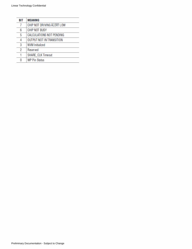
Linear Technology Confidential
Preliminary Documentation - Subject to Change

Linear Technology Confidential
Preliminary Documentation - Subject to Change
1. 2. 3.
What Example Firmware is Available from LTC?There are three sets of firmware:
eCos Board Controller ApplicationLinduinoLinux Drivers
eCos BC
The eCos application is a basic Board Controller written in an RTOS style. It supports:
SNMPTELNETFTPLUARS232 COMMAND LINETelemetry logging to SDAlert managementMult-threading
If you can use a Freescale K60 or K70, you can have an application working in a few days. Or, it an be studied to learn how to write a stand aloneBC.
Linduino
The Linduino is comprised of a layered library and sketches. The LT_PMBUS library has the following layers:
PMBusSMBusI2CWire
There is also support for Group Protocol and In Flight Update. Sketches are available for most PSM devices.
Linux Drivers
Linux drivers are implemented in user mode based on /dev/i2c. A Wandboard and Yocto Linux was used to implement the code. The examplecode does not include block commands or ALERTB. The code should work on any Linux platform with a supporting i2c driver.
However, support for i2c is sparse, and the level of support is not uniform. If you work with a different platform, you may have to do some driverwork.

Linear Technology Confidential
Preliminary Documentation - Subject to Change
1. 2.
1. 2. 3. 4.
1. 2. 3.
What is In Flight Update and How do I use it?
In Flight Update Code
In Flight Update code is available in two forms:
LinduinoLinux
Both versions are written in C/C++, but the underlying PMBus drivers are different.
The purpose of using C++ was to allow switching on/off PEC on the fly without a lot of conditional logic.
How In Flight Update Works
In Flight Update applies an .ISP file that is exported from LTpowerPlay to a final design. LTpowerPlay creates an Intel Hex file with data records.This file is processed to create C Structs that are executed by an engine that applies PMBus commands.
The In Flight Update software is similar to LTC/Arrow programming. They both use the same file and record formats. However, OEM and .ISPfiles are different recipies. OEM recipes are for single devices in a programming socket, and .ISP files are for working boards with multipledevices.
How Many Devices Does it Program at a Time?
You can generate an In System Programming (.ISP) file for a whole board, subsets of a board, or single devices. LTpowerPlay exports the .ISPfile based on what is in the project tree.
How Do You Port In Flight Update?
Typically the following things have to be addressed:
EndiannessStructure packing32 bit pointer castingPMBus API
The exist example code from eCos and Linduino determine the endianness of the example code. You may have to change it. Structures arepacked because the Intel Hex records are just binary data that is mapped into packed structs with pointers. This means the memory layout is inthe data, and packing structures matches this.
The pointer casting is only an issue if the code is ported to anything other than a 32 bit address processor.
The PMBus API can be managed in multiple ways:
Implement the PMBus.h for your platformPort the PMBus layers to your platformRewrite the PMBus calls
How Do You Debug In Flight Update?
There are #defines to turn on print statements. You can also spy on PMBus traffic with a Beagle.
What is the .ISP File Format?
See http://www.ltpowerplay.com/in_circuit_programming/
LTC3882 Pre-Release Si Compatibility
The LTC3882 released two pre-release versions of silicon to the field. These versions had very different register maps from final Si. The packingcodes for these versions were 0x0400 and 0x0500. Device programming (including In Flight Update) is not supported for these pre-releaseversions of the product. LTpowerPlay generates .ISP and OEM files for the final silicon which has code . If you are trying to perform In0x420xFlight Update on pre-release silicon on a customer board, it will fail on the packing code check. You must move to production silicon for In FlightUpdate to work properly.

Linear Technology Confidential
Preliminary Documentation - Subject to Change
What's This Fault?This FAQ Section provides detailed help for faults/warnings/status that you may encounter using various parts with LTpowerPlay. This is thestaging grounds for content that will ultimately be deployed with LTpowerPlay in the "What's this Fault? Tool". Some of this content may be indraft form, so please bear that in mind when reading it.
The names of the individual pages in this section are titled to match the items that are shown in the FAULT_WARN_LIST pseudo-register inLTpowerPlay. This pseudo-register is visible in the Telemetry/Status panel, and summarizes the faults/warnings/status for the selected channel. A new tool called the "What's this Fault? Tool" lists each of the statuses shown in the FAULT_WARN_LIST register and allows you to get detailedhelp on the selected status item of interest. The content from the subpages of this section are displayed when you select an item in the "What'sthis Fault? Tool".
Note that this content is under active devleopment, so you may encounter scenarios where the selected status item does not yet have detailedhelp. In this case, LTpowerPlay will tell you that no content is available and will direct you to the part's datasheet for further information. If youhave encountered this and the content is not located in this section, and you still need help, please contact your local LT Field Salesrepresentative for further help.What's This Fault? Topics

Linear Technology Confidential
Preliminary Documentation - Subject to Change
CML_INVALID_COMMANDThe device a command code that is unsupported via I2C
Possible Causes:
Attempted to write an unsupported register using I2C
Scope Debug
Trigger a scope on the falling edge of ALERTB while probing SCL/SDAGo Offline and then back Online in LTpowerPlay (forces a refresh of GUI cache values)Click Write All in LTpowerPlayObserve the command that was written to the device immediately preceding the falling ALERTB signal.

Linear Technology Confidential
Preliminary Documentation - Subject to Change
CML_INVALID_DATA
The device received improper data for a supported command.
Possible Causes:
Attempted to write an unsupported value to a register using I2CA configuration stored in the EEPROM has an invalid combination of configuration values (i.e. VOUT higher than range allows)
Remedies and Workarounds
Here are some experiments you can try to narrow things down:
Read the configuration into LTpowerPlay and click the "DRC" button in the toolbar to check for problemsPower Cycle the device and see if the problem returns,
If so, the unsupported data is programmed into NVMIf not, the unsupported data is programmed in to RAM only
Further Isolate which register(s) are causing the problemIssue a CLEAR_FAULTSSelect registers one at a time in the 'All Global' and 'All Paged' (be sure to go through each page), and write the individualregister (F12)
Look for the CML_INVALID_DATA fault to re-apper, indicating the offending commandDebug with Scope
Trigger a scope on the falling edge of ALERTB while probing SCL/SDAGo Offline and then back Online in LTpowerPlay (forces a refresh of GUI cache values)Click Write All in LTpowerPlayObserve the command that was written to the device immediately preceding the falling ALERTB signal.

Linear Technology Confidential
Preliminary Documentation - Subject to Change
CML_OTHER_COM_FAULT
The device detected traffic on the bus that does not match expected protocols.
Possible Causes:
Improper SmBus readA valid read from a PmBus device requires first sending a start, then address+write, then the command code, and then arepeated start (without a stop), before reading bytes from the slaveA common error for people familiar with I2C is to issue a stop, and then a new start with the address+read bit. This is invalid andPmBus devices are required to pull ALERTB low and set this fault to signal to the host that it is communicating improperly
Poor signal integrity on the busOther unexpected protocol.A temporary bus disruption (perhaps a device powering up that glitches or holds one of the lines low for some period of time)Master wrote or read too few bits. I2C is byte oriented. If the slave sees a stop condition in the middle of a byte (before 8-bits+ACK), itwill set this error bit.Master wrote too few bytes. If the master sends a stop condition after writing too few bytes (i.e. after sending 1 of 2 required bytes), theslave will set this error bit.One some devices, if the device sees an empty start/stop sequence will trigger this fault.
Clock remains high while data goes low (start) then high (stop)Some devices (like DC1613A, FPGAs or other logic) may issue such sequences from time to timeFor devices that flag this fault, these devices typically also support SMB_ALERT_MASK. If you are unable to avoid creating thefault, you can mask this fault from pulling ALERTB low by using the SMB_ALERT_MASK feature.
A device has just come out of reset or busy state (fault log, reset, restore, etc) and when it is first available, sees a partial transactionwhich looks like one of the above conditions or illegal protocol.
NOTE: Marginal timing on the bus (too slow rise/fall times, or violation of setup time specs) may produce scenarios that to the slave look likeillegal protocol. It is recommended that you verify the signal integrity of the I2C lines in this scenario.
Remedies and Workarounds
Here are some experiments you can try to narrow things down:
Decrease the bus speed (View > Preferences) and see if the problem goes awayClear the fault and see if it returns / is recurrentDisable any other masters that may be conflicting with LTpowerPlay
Only one master should be communicating with the system at a time. If you wish, you can disable LTpowerPlay by 'going offline'If you believe that there are no other masters, but want to double check, a quick way to do this is to configure the device inquestion to 'require PEC' (MFR_CONFIG_ALL). Then take LTpowerPlay offline. If the ALERTB pin is pulled low, connectLTpowerPlay again and see if there is a CML_PEC error. If so, this probably indicates that there is another master on the bus
Other Debugging Tips
There are a number of scenarios which can create a CML_OTHER_COM_FAULT. If you have an oscilloscope, perhaps the fastest way to insightis to:
Trigger the scope on the falling edge of the ALERTB signal, and Look at SCL/SDA signals at the pins of the IC
The ALERTB signal will be pulled low by the IC at the time of the fault, indicating the time of the fault. Look at SCL/SDA immediately precedingthis for clues. If possible, use a scope (preferred) with I2C Decode (or if not available alternately an I2C sniffer) to inspect the protocol leading upto the fault

Linear Technology Confidential
Preliminary Documentation - Subject to Change
CML_PEC_FAILEDThe device received an additional byte beyond the required number of bytes, and the additional byte failed to match the correct PEC CRC valuefor the byte stream.
Possible Causes:
Wrote too many bytes (i.e. 16 bit write to an 8-bit register)Wrote incorrectly computed PEC byteSignal Integrity issues with I2CPerturbation of the I2C bus
Remedies and Workarounds
Here are some experiments you can try to narrow things down:
Lower the bus speed (View > Preferences) and see if the problem goes awayClear the fault to see if it returns / is recurrentDisable other masters on the bus that may be conflicting with LTpowerPlay
Be sure only one master is talking at the same time. Optionally you can take LTpowerPlay 'offline'
Scope Debug
Trigger the scope on the falling edge of the ALERTB signal, and Look at SCL/SDA signals preceding the ALERTThis will tell you the offending command/data sequence and may illuminate other problems on the bus (contention, etc)

Linear Technology Confidential
Preliminary Documentation - Subject to Change
DAC_SATURATEDA DAC_SATURATED warning was detected because the DAC on this channel reached a maximum or minimum DAC value, and the VDAC pinhas reached its limit. The channel may also have faulted off due to an OV or UV.
Possible Causes:
Floating voltage too far away from VOUT_COMMAND voltage for servo’s compliance rangeDAC servo resistor value too highDAC servo resistor missing or crackedRegulator feedback resistor value(s) incorrect or assembly issueOPERATION register in Margin High or Margin Low state and DAC resistor value is too high
Remedies and Workarounds
Here are some experiments you can try to narrow things down:
Change DAC mode to disconnected and re-start the channel (if necessary) Observe READ_VOUT floating voltage and compare this value with VOUT_COMMAND setting. (Note: VOUT_COMMAND is the
) target value used by the servo loopDecrease DAC resistor value if the VDAC voltage does not have enough range to servo the output to the VOUT_COMMANDvoltage.
Change the to higher setting if the VDAC voltage needs to be greater. If the regulator's feedback voltage is 0.6V or 0.8V, usedac_gainthe lower gain setting (1.38V full scale). For feedback voltages of 1.2V, use the high gain setting (2.65V full scale).Generally speaking, DAC resistor values of > 1M ohm will cause DAC_SATURATED warnings.Change OPERATION register to 'On' (0x80), avoid Margin High and Margin Low states
Other Debugging Tips
There are a number of scenarios that can contribute to a DAC_SATURATED fault. If you have an oscilloscope, perhaps the fastest way to insightis to:
Probe the VDAC and VSENSE pins of the ICUnder typical conditions, the VDAC voltage will be within 100mV of the feedback voltage on a properly working channel, unless channelin margining state
Note: The ALERTB pin might not be asserted if no warnings or faults are detected.

Linear Technology Confidential
Preliminary Documentation - Subject to Change

Linear Technology Confidential
Preliminary Documentation - Subject to Change
DISCHARGE_FAULTAn DISCHARGE_FAULT warning was detected because the channel was commanded to turn on before the output voltage the ADC measuredthe VSENSE voltage below its programmable discharge percentage (MFR_VOUT_DISCHARGE_THRESHOLD * VOUT_COMMAND).
If Shared Fault propagation is enabled, this channel will also communicate this condition to other channels via holding the Shared Fault pin lowuntil the ADC measures a sufficiently low voltage on the VSENSE pins.
Example Fault Scenario
The waveform below illustrates an example discharge fault and associated system behaviors:
The example starts with the device in normal operating mode with no faults. The channel is commanded off and then on by the user. This can bevia the CONTROL pin, OPERATION command, or VIN rising above the programmable VIN_ON threshold, or combination thereof, depending onthe configuration of the channel. For a clearer understanding of the selected channels on/off behavior, select 'Utilities > On / Off Configuration...'in the menu.
a – The channel is commanded off. This may be because VIN dropped below VIN_OFF, the CONTROL pin was de-asserted, or thePmBus OPERATION=Off command was issuedb -- In response to the off condition, the channel's output enable is disabled, typically immediately, though options exist to honor theTOFF_DELAY before disabling (soft off). When using this configuration, the output enable should be connected to a power supply sothat de-asserting it disables the managed power supply.
c – The channel is subsequently commanded back on via VIN/CONTROL/OPERATION or a combination. See the On / Off Configuration
tool for a list of requirements for turn on.d -- At the time the channel is commanded on, the present ADC reading of the VSENSE pins is compared to the discharge threshold(VOUT_COMMAND* MFR_VOUT_DISCHARGE_THRESHOLD). If the ADC reading (subject to ADC latency) is above this threshold, aDISCHARGE_FAULT is declared. In the case (as in our example) that the channel is propagating faults to a shared fault pin, it willde-assert the shared fault pin signalling the DISCHARGE_FAULT to other channelse -- In our example, at this point the VSENSE voltage (at the pins of the device) has decayed below the discharge threshold. However,the ADC is subject to tADC latency (consult datasheet)f – When the ADC has measured the VSENSE voltage drop below the discharge threshold (0 to tADC after the physical voltage hasdropped below the threshold), the channel is ready to trigger a coordinate re-sequence of the system. It releases the shared fault pin tosignal that it is ready, and initiate time=zero of the coordinated resequence.

Linear Technology Confidential
Preliminary Documentation - Subject to Change
g – During the coordinated re-sequence, each channel, after waiting its programmed on delay (TON_DELAY) will start ramping itsvoltage up
Controllers have the ability to ramp the voltage directly, and will ramp the output consistent with the programmed TON_RISEsetting.Managers will assert the assert the VOEN pin to enable the managed supply at this time
This coordination feature insures that when power is toggled or when channels are toggled off/on, each channel is below its required dischargethreshold before a coordinated re-sequence is attempted.
Possible Causes:
Output Enable not connected to managed supply (board or assembly error)External device is over driving output enable (i.e. unprogrammed FPGA) Too short a MFR_RESTART_DELAY, or toggling off/on too fastDischarge threshold too low
Remedies and Workarounds
Here are some things you can try to narrow things down:
Increase the MFR_VOUT_DISCHARGE_THRESHOLD and see if the problem goes away ( 0.5 means 50% of VOUT_COMMAND, 0.6meant 60%, etc)Disable the MFR_VOUT_DISCHARGE_THRESHOLD ( > 1 is disabled)Increase the MFR_RESTART_DELAY to stretch the length of disable pulses on the CONTROL pin
Other Debugging Tips
Check for glitches (quick toggles) on the CONTROL pin. If you have an oscilloscope, perhaps thefastest way to insight is to:
Probe the VSENSE pins of the IC Probe the CONTROL input
Alternately if CONTROL is not used, probe the output enable signalTrigger the scope on the falling edge of ALERTB
The ALERT pin will be pulled low at the time of the DISCHARGE_FAULT. If the control pin is toggled too quickly, try the remedies andworkarounds above to stretch the interval, or correct the source of the problem. If the output is not disabled when the output enable isde-asserted, check the connection between the output enable and the power supply. There may be a missing or failed connection (crackedresistor, etc).

Linear Technology Confidential
Preliminary Documentation - Subject to Change
FACTORY_TRIM_CRC_FAULT
The device has an internal inconsistency in its EEPROM. This is often an indication the power wasremoved during a STORE operation or the device was incorrectly programmed.
Possible Causes:
Power was removed during a STORE_USER_ALL operation before the write to EEPROM completedThe device was programmed with data incorrectlyOne or more bits in the EEPROM have changed from their initial value
Remedies and Workarounds
Avoid removing power during a STORE_USER_ALL operation until the operation is completeFor an improperly programmed device, re-program the device 'in system' using the programming utility

Linear Technology Confidential
Preliminary Documentation - Subject to Change
FAULT0_INThe channel was turned off or prevented from turning on at least once because a shared FAULTB pin was asserted low and the channel isconfigured to respond to the pin. The root cause item of interest is either another channel or external device in the system that asserted the pinlow.
Shared Fault Pins are used as a bi-directional fault coordination bus for other PSM devices or external devices. Some PSM devices name theshared fault pin "FAULTBX" while others name it "GPIOB". GPIOB pins can be used for other purposes as well, but are typically used for faultsharing. See the next section for a better understanding of how fault sharing behavior works.
FAULT0_IN indicates a specific fault pin that the channel is responding to. For devices that have two FAULTB pins, this status indicatesFAULTB0 pin as the source. For devices that support 4 FAULTB pins, FAULT0_IN indicates the FAULTB00 pin for channels 0-3, and theFAULTB01 pin for channels 4-7 of the device.
Device Behavior in a Shared Fault Scenario
The example waveform above illustrates fault sharing behavior of the 'root offender' channel in conjunction with a 'responder channel'.
NOTE: This is one specific example for the purpose of understanding. The following events occur in the example:
a -- A channel (called 'root offender') encounters a fault (over voltage in this example) with a non-ignore response setting, and disables itsoutput (example VOUT_OV_FAULT_RESPONSE= Deglitched Off, Infinite Retry)b -- When its output is disabled, the root offender, if configured to to a shared fault pin (FAULTB OR GPIOB) will immediatelypropagatepull low on the open drain shared fault pin.c -- A responder channel (configured to to the shared fault pin) will immediately stop power delivery (immediate off)respond
For PSM Controllers, power deliver is stopped by the controller itself, and the condition is reported as GPIOB_ASSERTED_LOFor PSM Managers, the output enable (VOEN) pin is de-asserted to disable the managed power supply, and the condition isreported as FAULTBX_IN
NOTE: The LTC2977, LTC2980, and LTM2987 may be optionally configured to honor off sequencing delays (TOFF_DELAY)before de-asserting the VOEN pin upon fault.
d -- After the root offender has waited its programmable retry delay (MFR_RETRY_DELAY), if the fault is no longer present (as in thisexample), it releases the open drain shared fault pin.
This signals to all responder channels that a re-sequence should occur. The rising edge of FAULTB sets time=zero for a coordinated re-sequence of the root offender and any responder channels.
e -- During the coordinated re-sequence, a responder channel, after waiting its programmed on delay (TON_DELAY) will start ramping itsvoltage up
Controllers have the ability to ramp the voltage directly, and will ramp the output consistent with the programmed TON_RISEsetting.Managers will assert the assert the VOEN pin to enable the managed supply at this time

Linear Technology Confidential
Preliminary Documentation - Subject to Change
Possible Causes:
Missing a pullup on the FAULTB pin Another chip or channel is pulling the FAULTB pin low. Check the rest of the system for faults:
If the responder channel remains off, the 'Why am I Off?' will provide a succinct list of faults in your systemAn External Device other than a LTC device may be holding FAULTB low.
Check the schematic for any other devices that may be connected to the GPIOB pin (an unprogrammed FPGA for instance)You may also scan the system for faults manually:
Select the FAULT_WARN_LIST pseudo-register in the Telemetry/Status windowUse the 'All Pages in System' view to scan the FAULT_WARN_LIST across the system to see all faults/warnings in the system inone place. If there are any 'red' channels in the system tree, focus on these channels first.Look for critical or important faults (OV, OC, OT, etc) on another chip that is propagating to the FAULTB pin
Remedies and Workarounds
Here are some experiments you can try to narrow things down:
Configure the channel to ignore the FAULTB pin in the "Fault Sharing" Section of the configuration. This will allow the channel to startupup regardless of the pin.To determine if the 'root cause' is a PSM device or external source (unprogrammed FPGA, etc) driving the pin low:
Disable propagation to FAULTB/GPIOB for all devices in the systemIf the FAULTB pin remains low, this indicates an external device or circuit may be keeping the pin low.
If the DRC check produces any warnings, fix these and see if the problem goes away.
Other Debugging Tips
If the channel is presently off, use the "Why am I Off? Tool". Otherwise, if you have an oscilloscope, do the following:
Trigger the scope on the falling edge of the FAULTB pin and Look at other possible signals in the system that may be responsible driving FAULTB lowDisable fault propagation for all devices. If the pin is still low, trace the schematic for any devices connected to the pin and insure theyare not driving it low.
Latch Off Shared Fault Response
NOTE: The behavior of a shared fault pin is determined by the programmed fault response of the root offender. The example above shows acase where the root offender is configured to automatically retry after the fault occurs. In cases where the root offender's fault response isprogrammed to 'latch off' without retry, external user action (off then on) is required to re-sequence the system. Note that a CLEAR_FAULTScommand will only clear fault status bits, and will NOT have functional effects on the shared fault pins or enable states of supplies.
The example waveform below illustrates fault sharing behavior of the 'root offender' channel in conjunction with a 'responder channel' when theroot offender is configured to 'latch off'.

Linear Technology Confidential
Preliminary Documentation - Subject to Change
NOTE: This is one specific example for the purpose of understanding. The following events occur in the example:
a -- A channel (called 'root offender') encounters a fault (over voltage in this example) with a 'latch off' response setting, and disables itsoutput (example VOUT_OV_FAULT_RESPONSE= Deglitched Off, NO Retry)b -- When its output is disabled, the root offender, if configured to to a shared fault pin (FAULTB OR GPIOB) will immediatelypropagatepull low on the open drain shared fault pin.c -- A responder channel (configured to to the shared fault pin) will immediately stop power delivery (immediate off)respond
For PSM Controllers, power deliver is stopped by the controller itself, and the condition is reported as GPIOB_ASSERTED_LOFor PSM Managers, the output enable (VOEN) pin is de-asserted to disable the managed power supply, and the condition isreported as FAULTBX_IN
NOTE: The LTC2977, LTC2980, and LTM2987 may be optionally configured to honor off sequencing delays (TOFF_DELAY)before de-asserting the VOEN pin upon fault.
NOTE that absent external action, the system will remain in this state. The root offender remains 'latched off', and it also holds its sharedfault pin low to communicate to the rest of the system it should also remain off.
d -- At some later time, an external action commands the root offender off. This could be due to one or more of the following conditions:VIN drops below the programmed VIN_OFF thresholdThe CONTROL/RUN pin is toggled to the logical 'off' stateThe PmBus OPERATION command (or ON_OFF_CONFIG) commands the channel off
e -- An external action commands the root offender on again (off then on). The external On request could be due to one or more of thefollowing conditions:
VIN rises above the programmed VIN_ON thresholdThe CONTROL/RUN pin is toggled to the logical 'on' stateThe PmBus OPERATION command (or ON_OFF_CONFIG) commands the channel on
f -- Upon seeing the external off then on request, the root offender releases the open drain shared fault pin. This signals to all responder channels that a re-sequence should occur. The rising edge of FAULTB sets time=zero for a coordinated re-sequence of the root offender and any responder channels.
g -- During the coordinated re-sequence, a responder channel, after waiting its programmed on delay (TON_DELAY) will start ramping itsvoltage up
Controllers have the ability to ramp the voltage directly, and will ramp the output consistent with the programmed TON_RISEsetting.Managers will assert the assert the VOEN pin to enable the managed supply at this time

Linear Technology Confidential
Preliminary Documentation - Subject to Change
FAULT1_INThe channel was turned off or prevented from turning on at least once because a shared FAULTB pin was asserted low and the channel isconfigured to respond to the pin. The root cause item of interest either another channel or external device in the system that asserted the pin low.
Shared Fault Pins are used as a bi-directional fault coordination bus for other PSM devices or external devices. Some PSM devices name theshared fault pin "FAULTBX" while others name it "GPIOB". GPIOB pins can be used for other purposes as well, but are typically used for faultsharing. See the next section for a better understanding of how fault sharing behavior works.
FAULT1_IN indicates a specific fault pin that the channel is responding to. For devices that have two FAULTB pins, this status indicatesFAULTB1 pin as the source. For devices that support 4 FAULTB pins, FAULT1_IN indicates the FAULTB10 pin for channels 0-3, and theFAULTB11 pin for channels 4-7 of the device.
Device Behavior in a Shared Fault Scenario
The example waveform above illustrates fault sharing behavior of the 'root offender' channel in conjunction with a 'responder channel'.
NOTE: This is one specific example for the purpose of understanding. The following events occur in the example:
a -- A channel (called 'root offender') encounters a fault (over voltage in this example) with a non-ignore response setting, and disables itsoutput (example VOUT_OV_FAULT_RESPONSE= Deglitched Off, Infinite Retry)b -- When its output is disabled, the root offender, if configured to to a shared fault pin (FAULTB OR GPIOB) will immediatelypropagatepull low on the open drain shared fault pin.c -- A responder channel (configured to to the shared fault pin) will immediately stop power delivery (immediate off)respond
For PSM Controllers, power deliver is stopped by the controller itself, and the condition is reported as GPIOB_ASSERTED_LOFor PSM Managers, the output enable (VOEN) pin is de-asserted to disable the managed power supply, and the condition isreported as FAULTBX_IN
NOTE: The LTC2977, LTC2980, and LTM2987 may be optionally configured to honor off sequencing delays (TOFF_DELAY)before de-asserting the VOEN pin upon fault.
d -- After the root offender has waited its programmable retry delay (MFR_RETRY_DELAY), if the fault is no longer present (as in thisexample), it releases the open drain shared fault pin.
This signals to all responder channels that a re-sequence should occur. The rising edge of FAULTB sets time=zero for a coordinated re-sequence of the root offender and any responder channels.
e -- During the coordinated re-sequence, a responder channel, after waiting its programmed on delay (TON_DELAY) will start ramping itsvoltage up
Controllers have the ability to ramp the voltage directly, and will ramp the output consistent with the programmed TON_RISEsetting.Managers will assert the assert the VOEN pin to enable the managed supply at this time
Possible Causes:

Linear Technology Confidential
Preliminary Documentation - Subject to Change
Missing a pullup on the FAULTB pin Another chip or channel is pulling the FAULTB pin low. Check the rest of the system for faults:
If the responder channel remains off, the 'Why am I Off?' will provide a succinct list of faults in your systemAn External Device other than a LTC device may be holding FAULTB low.
Check the schematic for any other devices that may be connected to the GPIOB pin (an unprogrammed FPGA for instance)You may also scan the system for faults manually:
Select the FAULT_WARN_LIST pseudo-register in the Telemetry/Status windowUse the 'All Pages in System' view to scan the FAULT_WARN_LIST across the system to see all faults/warnings in the system inone place. If there are any 'red' channels in the system tree, focus on these channels first.Look for critical or important faults (OV, OC, OT, etc) on another chip that is propagating to the FAULTB pin
Remedies and Workarounds
Here are some experiments you can try to narrow things down:
Configure the channel to ignore the FAULTB pin in the "Fault Sharing" Section of the configuration. This will allow the channel to startupup regardless of the pin.To determine if the 'root cause' is a PSM device or external source (unprogrammed FPGA, etc) driving the pin low:
Disable propagation to FAULTB/GPIOB for all devices in the systemIf the FAULTB pin remains low, this indicates an external device or circuit may be keeping the pin low.
If the DRC check produces any warnings, fix these and see if the problem goes away.
Other Debugging Tips
If the channel is presently off, use the "Why am I Off? Tool". Otherwise, if you have an oscilloscope, do the following:
Trigger the scope on the falling edge of the FAULTB pin and Look at other possible signals in the system that may be responsible driving FAULTB lowDisable fault propagation for all devices. If the pin is still low, trace the schematic for any devices connected to the pin and insure theyare not driving it low.

Linear Technology Confidential
Preliminary Documentation - Subject to Change
FAULT_LOG_PRESENTThe selected device has a non volatile fault log, either manually stored by the user or automatically stored at the time of a fault that disabled anoutput.
Possible Causes:
A root level fault (with a non-ignore fault response) disabled a channel on this chip and recorded a fault logThis device responded to a shared FAULTB pin by disabling one or more outputs and recorded a fault logThe user manually stored a 'snapshot' of telemetry data into the fault log via I2C
Tips
Typically it's easier to debug a system if power has not yet been removed. For instance, during board development, you can power the ICs fromthe dongle (and optionally DC2086A for many devices). When a problem occurs, it's easy to use the latched status registers to debug faults veryquickly. Otherwise, if power has been removed since the problem occurred, you can use the non volatile fault log for debugging.
If power has not yet been removed from the devices, and one or more outputs are OFF, use the Why am I Off? tool to quickly understandwhy a selected channel is offIf power has not yet been removed from the devices, scan the system for faults stored in latched registers:
Select the FAULT_WARN_LIST pseudo-register in the Telemetry/Status viewUse the 'All Pages in System' view to scan the entire system for potentially interesting faults.
If power has been removed, click the Fault Log button in the toolbar and read the fault log into the GUI for further analysis:
Other Debugging Tips
If you have an oscilloscope, perhaps the fastest way to insight is to:
Inspect the registers and the fault log for channels/signals of interest)Trigger the scope on the falling edge of the ALERTB signal, and Probe other signals of interest (preferably , and at the pins of the IC)
The ALERTB signal will be pulled low by the IC at the time of the fault, indicating the time of the fault.

Linear Technology Confidential
Preliminary Documentation - Subject to Change
GPIOB_ASSERTED_LOThe channel was turned off or prevented from turning on at least once because the channel's GPIOB pin was asserted low and the channel isconfigured to respond to the pin. The root cause item of interest either another channel or external device in the system that asserted the pin low.
Shared Fault Pins are used as a bi-directional fault coordination bus for other PSM devices or external devices. Some PSM devices name theshared fault pin "FAULTBX" while others name it "GPIOB". GPIOB pins can be used for other purposes as well, but are typically used for faultsharing. See the next section for a better understanding of how fault sharing behavior works.
Device Behavior in a Shared Fault Scenario
The example waveform above illustrates fault sharing behavior of the 'root offender' channel in conjunction with a 'responder channel'.
NOTE: This is one specific example for the purpose of understanding. The following events occur in the example:
a -- A channel (called 'root offender') encounters a fault (over voltage in this example) with a non-ignore response setting, and disables itsoutput (example VOUT_OV_FAULT_RESPONSE= Deglitched Off, Infinite Retry)b -- When its output is disabled, the root offender, if configured to to a shared fault pin (FAULTB OR GPIOB) will immediatelypropagatepull low on the open drain shared fault pin.c -- A responder channel (configured to to the shared fault pin) will immediately stop power delivery (immediate off)respond
For PSM Controllers, power deliver is stopped by the controller itself, and the condition is reported as GPIOB_ASSERTED_LOFor PSM Managers, the output enable (VOEN) pin is de-asserted to disable the managed power supply, and the condition isreported as FAULTBX_IN
NOTE: The LTC2977, LTC2980, and LTM2987 may be optionally configured to honor off sequencing delays (TOFF_DELAY)before de-asserting the VOEN pin upon fault.
d -- After the root offender has waited its programmable retry delay (MFR_RETRY_DELAY), if the fault is no longer present (as in thisexample), it releases the open drain shared fault pin.
This signals to all responder channels that a re-sequence should occur. The rising edge of GPIOB sets time=zero for a coordinated re-sequence of the root offender and any responder channels.
e -- During the coordinated re-sequence, a responder channel, after waiting its programmed on delay (TON_DELAY) will start ramping itsvoltage up
Controllers have the ability to ramp the voltage directly, and will ramp the output consistent with the programmed TON_RISEsetting.Managers will assert the assert the VOEN pin to enable the managed supply at this time
Possible Causes:
Missing a pullup on the GPIOB pin Another chip or channel is pulling the GPIOB pin low. Check the rest of the system for faults:
If the responder channel remains off, the 'Why am I Off?' will provide a succinct list of faults in your systemAn External Device other than a LTC device may be holding GPIOB low.

Linear Technology Confidential
Preliminary Documentation - Subject to Change
Check the schematic for any other devices that may be connected to the GPIOB pin (an unprogrammed FPGA for instance)You may have a misconfiguration that may keep the GPIOB low. Read the configuration and click the "DRC" button in the toolbar tocheck it.You may also scan the system for faults manually:
Select the FAULT_WARN_LIST pseudo-register in the Telemetry/Status windowUse the 'All Pages in System' view to scan the FAULT_WARN_LIST across the system to see all faults/warnings in the system inone place. If there are any 'red' channels in the system tree, focus on these channels first.Look for critical or important faults (OV, OC, OT, etc) on another chip that is propagating to the GPIOB/FAULTB pin
Remedies and Workarounds
Here are some experiments you can try to narrow things down:
Configure the channel to ignore the GPIOB pin in the "Fault Sharing" Section of the configuration. This will allow the channel to startupup regardless of the pin.To determine if the 'root cause' is a PSM device or external source (unprogrammed FPGA, etc) driving the pin low:
Disable propagation to GPIOB/FAULTB for all devices in the systemIf the GPIOB pin remains low, this indicates an external device or circuit may be keeping the pin low.
If the DRC check produces any warnings, fix these and see if the problem goes away.
Other Debugging Tips
If the channel is presently off, use the "Why am I Off? Tool". Otherwise, if you have an oscilloscope, do the following:
Trigger the scope on the falling edge of this channel's GPIOB pin and Look at other possible signals in the system that may be responsible driving GPIOB lowDisable fault propagation for all devices. If the pin is still low, trace the schematic for any devices connected to the pin and insure theyare not driving it low.

Linear Technology Confidential
Preliminary Documentation - Subject to Change
INPUT_OFFAn INPUT_OFF warning is detected because the VIN_SNS pin voltage is below the VIN_OFF setting. The device will also typically holdSHARE_CLK low preventing other devices from turning on.
Device Behavior for VIN and SHARE_CLK
This section provides background information for a deeper understanding of how devices behave and coordinate when VIN is lost or applied.
The example waveform above illustrates how a device behaves when its VIN is lost. It also describes how devices communicate this condition toeach other via the SHARE_CLK signal to insure coordinated behavior. The example starts with the device in normal operating mode with nofaults. Typically the SHARE_CLK signal is connected between PSM devices to insure coherent sequencing. Let's take the scenario where VINfor the system is removed and then re-applied. The behavior of the system is as describe in the following sequence points highlighted above:
a – The system is operating normally, with VIN good and no faults. SHARE_CLK is toggling normally to provide a common arbitratedtimebase across devices for sequencing.b -- A device in the system detects that its VIN voltage drops below its programmed VIN_OFF threshold. c – The first such device to see VIN drop below VIN_OFF immediately holds SHARE_CLK low to signal to the system that VIN was lost,and a normal power down should occurd -- When a channel (of any device connected to the common SHARE_CLK) detects that the SHARE_CLK has stopped, it immediatelydisables its output
For PSM Controllers, power deliver is stopped by the controller itselfFor PSM Managers, the output enable (VOEN) pin is de-asserted to disable the managed power supply
e -- VIN ramps back up. Devices detect when VIN rises above their programmed VIN_ON threshold, and release the commonSHARE_CLK.f – When the last such device in the system detects VIN rising above its programmed VIN_ON threshold, it releases the commonSHARE_CLK signal and the SHARE_CLK starts toggling again. Devices connected to SHARE_CLK detect that SHARE_CLK hasstarted, and initiate a coordinated re-sequence (the start of SHARE_CLK marks time=zero).f – During the coordinated re-sequence, each channel, after waiting its programmed on delay (TON_DELAY) will start ramping its voltageup
Controllers have the ability to ramp the voltage directly, and will ramp the output consistent with the programmed TON_RISEsetting.Managers will assert the assert the VOEN pin to enable the managed supply at this time

Linear Technology Confidential
Preliminary Documentation - Subject to Change
This coordination feature insures that as power is applied (or lost) the system remains coordinated in its sequencing behavior, and all devicesagree on time=zero for up sequencing, and turn off immediately when VIN is lost.
Possible Causes:
VIN not appliedVIN_ON setting is too highBoard or assembly error between the VIN_SENSE pins of the device and the VIN sensed (missing or cracked resistor, etc)
Remedies and Workarounds
Here are some things you can try to narrow things down:
Apply sufficient VIN voltage (as seen by VIN_SNS pin)Change VIN_ON and VIN_OFF settings to lower values
Other Debugging Tips
Even if VIN is applied and > VIN_ON, all channels may be Off due to SHARE_CLK pin being held lowIf this is the case, check that other PSM devices that use SHARE_CLK are not detecting a VIN problem

Linear Technology Confidential
Preliminary Documentation - Subject to Change
IOUT_OC_FAULTAn IOUT_OC fault was detected because the differential voltage seen on the ISENSE pins reached the IOUT_OC_FAULT_LIMIT.
Possible Causes:
A fast transient may have occurred. The current supervisor's update rate is 12us.IOUT_CAL_GAIN is set too low.IOUT_OC_FAULT_LIMIT is set too low.If sensing current by inductor DCR, that is not captured by a scopeOutput has heavier load than expected or is shorted to GND.
Remedies and Workarounds
Here are some experiments you can try to narrow things down:
Changing the output current limits may resolve the problem, but possibly not. There is a deglitched fault response that might help. Set theIOUT_OC_FAULT_RESPONSE to deglitched and set the delay_count to a non-zero value. The delay_count value represents how many12us periods the supervisor checks for an OC condition. Change IOUT_CAL_GAIN to a larger value which will then translate to a lower output current value.
Other Debugging Tips
There are a number of scenarios which can create a IOUT_OC fault. If you have an oscilloscope, perhaps the fastest way to insight is to:
Trigger the scope on the falling edge of the ALERTB signal, and Look at the ISENSE and VSENSE pins at the IC.
The ALERTB signal will be pulled low by the IC at the time of the fault.

Linear Technology Confidential
Preliminary Documentation - Subject to Change
OFFThe selected channel is Off. This may be due to a number of possible reasons.
Possible Causes:
TIP: Please use the ' . If you do not see the tool, clickWhy am I Off?' tool in the upper right corner of LTpowerPlay for further insight'View > Restore Default Layout' in the menu. Below is a list of common reasons that a channel may be off:
Commanded off via I2CCommanded off via logic pin (RUN/CONTROL)SHARE_CLK is not pulled up or pulled low, keeping the channel from turning onWDI_RESET is pulled low, keeping the IC in reset (this also prevents communication with the device)
One or more faults configured as non-ignore may have occurred
The GPIOB/FAULTB pin may be asserted lowVin may be below the programmable VIN_OFF threshold, which forces channels off

Linear Technology Confidential
Preliminary Documentation - Subject to Change
OT_FAULTAn OT_FAULT was detected because the temperature exceeded the OT_FAULT_LIMIT value. This fault applies to the die temperature on the2977/2978 devices but is a paged fault on all other SPM devices. The OT/UT warning and fault limits and response are global registers on the2977/78 and are paged on all other PSM devices.
Possible Causes:
If the device is a LTC2977/78, this fault indicates that high temperature was detected on the internal 2977/78 die Otherwise, the fault indicates that high temperature was detected on an external temperature sensor on this PSM channel.OT_FAULT_LIMIT set too low.External TSENSE pin is floating.
Remedies and Workarounds
Check for floating External TSENSE pins (if applicable) and ground them.If a VSENSE pin is floating, it is possible that the internal die temp measurement is grossly in error, causing an OT or UT fault or warning.
Other Debugging Tips
For 2977/78 devices, only an internal die temperature is available and therefore the OT/UT warn and fault limits are applied to the measured dietemperature. For all other PSM devices, the OT/UT warn and fault limits are paged and applied to each channel’s external TSENSE pin; thereare no internal die temp limits for these devices.

Linear Technology Confidential
Preliminary Documentation - Subject to Change
PLL_UNLOCKED
The PLL_UNLOCKED status bit is set because the PWM could not lock on the external clock suppliedto the SYNC pin.
Possible Causes:The SYNC pin is shorted to ground or supplyThe external clock frequency is less than 1/2 the programmed PWM frequencyThe external clock has too much jitter on the falling edgeThe PWM frequency was changed via the PMBus
Remedies and Workarounds
Here are some experiments you can try to narrow things down:
Check that VIN for the power stage is presentCheck the READ_FREQUENCY register in the telemetry view; if it is low, zero, or or greater than 10% off the programmed value, theremay be a SYNC clock issueProbe the SYNC Clock and insure that the frequency is somewhat near to the programmed clock rate; otherwise, you may have a SYNCclock issueClear the fault and see if it returns
Other Debug Tips
The LTC3882 is more sensitive to PWM unlock because it has less filtering on the fault detector than current mode devicesIn general, SYNC should be set to output on one device, and input on all other devicesThe PLL detects the external clock on the falling edgeA boot strap design that uses internal SYNC that is then over driven by an external clock may not start the external clock cleanly andcause a fault

Linear Technology Confidential
Preliminary Documentation - Subject to Change
SHARE_CLK_LOWThe channel is being held off because the SHARE_CLK signal is low. The open drain SHARE_CLK signal is a bi-directional open draincoordination signal used between devices to enforce time=zero and time delay synchronization.
NOTE: The 'Why am I Off?' tool may provide additional insights.
Device Behavior for VIN and SHARE_CLK
The example waveform above illustrates the behavior of a the SHARE_CLK signal in response to VIN, and the behavior of device channels inresponse to SHARE_CLK stopping and restarting. The example starts with the device in normal operating mode with no faults. Typically theSHARE_CLK signal is connected between PSM devices to insure coherent sequencing. Let's take the scenario where VIN for the system isremoved and then re-applied. The behavior of the system is as describe in the following sequence points highlighted above:
a – The system is operating normally, with VIN good and no faults. SHARE_CLK is toggling normally to provide a common arbitratedtimebase across devices for sequencing.b -- A device in the system detects that its VIN voltage drops below its programmed VIN_OFF threshold. c – The first such device to see VIN drop below VIN_OFF immediately holds SHARE_CLK low to signal to the system that VIN was lost,and a normal power down should occurd -- When a channel (of any device connected to the common SHARE_CLK) detects that the SHARE_CLK has stopped, it immediatelydisables its output
For PSM Controllers, power deliver is stopped by the controller itselfFor PSM Managers, the output enable (VOEN) pin is de-asserted to disable the managed power supply
e -- VIN ramps back up. Devices detect when VIN rises above their programmed VIN_ON threshold, and release the commonSHARE_CLK.f – When the last such device in the system detects VIN rising above its programmed VIN_ON threshold, it releases the commonSHARE_CLK signal and the SHARE_CLK starts toggling again. Devices connected to SHARE_CLK detect that SHARE_CLK hasstarted, and initiate a coordinated re-sequence (the start of SHARE_CLK marks time=zero).f – During the coordinated re-sequence, each channel, after waiting its programmed on delay (TON_DELAY) will start ramping its voltageup
Controllers have the ability to ramp the voltage directly, and will ramp the output consistent with the programmed TON_RISEsetting.Managers will assert the assert the VOEN pin to enable the managed supply at this time
This coordination feature insures that as power is applied (or lost) the system remains coordinated in its sequencing behavior, and all devicesagree on time=zero for up sequencing, and turn off immediately when VIN is lost.

Linear Technology Confidential
Preliminary Documentation - Subject to Change
Possible Causes:
Missing or wrong pullup, preventing SHARE_CLK from toggling properly. Consult the datasheet for proper pullup selection.Missing board connection (cracked or missing 0 ohm resistor to common SHARE_CLK, board/assembly error, etc)One or more PSM devices in the system are holding SHARE_CLK low
They may be in RESET, or Their VIN may be below their programmed VIN_ON threshold.
An external device (for example an unprogrammed FPGA) is holding SHARE_CLK low
Remedies and Workarounds
Here are some experiments you can try to narrow things down:
Configure the channel to ignore the FAULTB pin in the "Fault Sharing" Section of the configuration. This will allow the channel to startupup regardless of the pin.To determine if the 'root cause' is a PSM device or external source (unprogrammed FPGA, etc) driving the pin low:
Disable propagation to FAULTB/GPIOB for all devices in the systemIf the FAULTB pin remains low, this indicates an external device or circuit may be keeping the pin low.
If the DRC check produces any warnings, fix these and see if the problem goes away.
Other Debugging Tips
If the channel is presently off, use the "Why am I Off? Tool". Otherwise, if you have an oscilloscope, do the following:
Trigger the scope on the falling edge of the FAULTB pin and Look at other possible signals in the system that may be responsible driving FAULTB lowDisable fault propagation for all devices. If the pin is still low, trace the schematic for any devices connected to the pin and insure theyare not driving it low.

Linear Technology Confidential
Preliminary Documentation - Subject to Change
TON_MAX_FAULT
A TON_MAX fault was detected because the VSENSE voltage did not reach theVOUT_UV_FAULT_LIMIT before the TON_MAX_FAULT_LIMIT.
Possible Causes:Output is shorted, preventing Vout ramp.TON_MAX_FAULT_LIMIT set shorter than Vout’s ramp up time
Large soft start capVOUT_UV_FAULT_LIMIT set too high.Regulator feedback resistor value(s) incorrect or assembly issue.VOUT_EN pin has no pullup resistor or power supply enable/RUN pin not pulled high.VOEN not physically connected to the power supply enable/RUN pin (failed or missing connection)Power supply's input is not enabled, or too weak for regulation
If its input is sequenced, enable it this channelbefore
Remedies and Workarounds
Here are some experiments you can try to narrow things down:
Increase TON_MAX_LIMIT to see if the problem goes awaySet TON_MAX_FAULT_RESPOSNE to 'ignore' to see if the output voltage comes upLower the VOUT_UV_FAULT_LIMIT and see if the problem goes away
Other Debugging Tips
There are a number of scenarios which can create a TON_MAX_FAULT. If you have an oscilloscope, perhaps the fastest way to insight is to:
Trigger the scope on the falling edge of the ALERTB signal, and Look at the VOEN and VSENSE , and at the pins of the ICVIN for the offending channel.
The ALERTB signal will be pulled low by the IC at the time of the fault, indicating the time of the fault.

Linear Technology Confidential
Preliminary Documentation - Subject to Change
UT_FAULTA UT_FAULT was detected because the measured temperature was less than the UT_FAULT_LIMIT value. This fault applies to the dietemperature on the 2977/2978 devices but is a paged fault on all other PSM devices. The OT/UT warning and fault limits and responses areglobal registers on the 2977/78 and are paged on all other PSM devices.
Possible Causes:
If the device is a LTC2977/78, low temperature was detected on either the internal dieOtherwise (all other PSM devices) this fault indicates low temperature was detected on an external temperature sensor on this PSMchannel.UT_FAULT_LIMIT set too highA VSENSEP pin is floatingExternal TSENSE pin is floating
Remedies and Workarounds
If applicable, check for floating TSENSE pins and ground themIf a VSENSE pin is floating, it is possible that the internal die temp measurement is grossly in error, causing an OT or UT fault orwarning.
Other Debugging Tips
For 2977/78 devices, only an internal die temperature is available and therefore the OT/UT warn and fault limits are applied to the measured dietemperature. For all other PSM devices, the OT/UT warn and fault limits are paged and applied to each channel’s TSENSE pin; there are nointernal die temp limits for these devices.

Linear Technology Confidential
Preliminary Documentation - Subject to Change
VOUT_OV_FAULTA VOUT_OV fault was detected because a voltage greater than the VOUT_OV_FAULT_LIMIT was detected on this channel’s VSENSE pin.
Possible Causes:
VOUT_OV_FAULT_LIMIT set too low.Regulator feedback resistor value(s) incorrect or assembly issue.VOUT_COMMAND setting too high and DAC/servo moved output above VOUT_OV_FAULT_LIMIT.Too short TON_RISE, causing the PSM Manager to prematurely soft connect during the voltage ramp.
Remedies and Workarounds
Here are some experiments you can try to narrow things down:
Increase VOUT_OV_FAULT_LIMIT (or decrease VOUT_COMMAND) to see if the problem goes awaySet VOUT_OV_FAULT_RESPONSE to deglitched and increase deglitch interval to see if problem goes awayLower the VOUT_UV_FAULT_LIMIT and see if the problem goes away
Other Debugging Tips
With an OV fault, it's best to be safe and look at the signals with an oscilloscope. Do the following:
Trigger the scope on the falling edge of the ALERTB signal, and Look at VSENSE pins , and at the ICVIN for the offending channel (or other signals of interest)
The ALERTB signal will be pulled low by the IC at the time of the fault, indicating the time of the fault.

Linear Technology Confidential
Preliminary Documentation - Subject to Change
VOUT_UV_FAULTA VOUT_UV fault was detected because a voltage less than the VOUT_UV_FAULT_LIMIT was detected on this channel’s VSENSE pin.
Possible Causes:
VOUT_UV_FAULT_LIMIT set too high.VOUT_COMMAND setting too low and DAC/servo moved output below VOUT_UV_FAULT_LIMIT.Regulator feedback resistor value(s) incorrect or assembly issue.The enable/RUN pin of the device was disabled externally while the channel was ONThe channel dipped under a load after sequencing up properly (after TON_MAX_FAULT_LIMIT)
Remedies and Workarounds
Here are some experiments you can try to narrow things down:
Lower VOUT_UV_FAULT_LIMIT to see if the problem goes awaySet the VOUT_UV_FAULT_RESPONSE to 'deglitched off' and increase the deglitch interval until the problem goes awaySet the VOUT_UV_FAULT_RESPONSE to 'ignore' and see if the system sequences up. Then issue CLEAR_FAULTS to determinewhether the problem occurs during startup only or afterward.
Other Debugging Tips
One thing to keep in mind with UV faults are that they can only occur after the device has successfully risen above the VOUT_UV_FAULT_LIMITwithin the time budget of TON_MAX_FAULT_LIMIT after the output is enabled. This means that the output did come up initially, and then fellbelow the VOUT_UV_FAULT limit while the channel was ON. If you have an oscilloscope, perhaps the fastest way to insight is to:
Trigger the scope on the falling edge of the ALERTB signal, and Look at the VOEN and VSENSE , and at the pins of the ICVIN for the offending channel (or other relevant signals/channels)
The ALERTB signal will be pulled low by the IC at the time of the fault, indicating the time of the fault.

Linear Technology Confidential
Preliminary Documentation - Subject to Change
Design

Linear Technology Confidential
Preliminary Documentation - Subject to Change
How do you design the addressing of a PSM system?
How do you design the addressing of a PSM system?
App Note AN152 contains all the information required to:
Understand how PSM Controller and PSM Manager addresses worksHow to design the address map using address registers and external pinsHow to use bus muxes for large designs
See: http://cds.linear.com/docs/en/application-note/an152f.pdf