linde 336_gb_9512
TRANSCRIPT
Service Training
This document is only provided for your use during training and it remains the exclusive property ofLINDE AG Werksgruppe Flurförderzeuge und Hydraulik
Linde Electric Fork TruckE 20 / 25 / 30Series 336


Service Training
TABLE OF CONTENTS
2 Linde electric fork truck E 20 / 25 / 30 Series 336 1
2.1 Drive - Motor 1
2.1.1 Traction motor to 6/95 1
2.1.2 Traction motor from 7/95 3
2.1.3 Checking and renewing the traction motor brushes 5
2.1.4 Traction motor disassembling 6
2.1.5 Fan 8
2.1.6 Speed sensor 8
2.2 Drive - Gearbox 1
2.2.1 Drive axle removal 2
2.2.2 Drive axle disassembly and assembly 4
2.2.3 Planetary hub reduction gearbox (from 1/95 to 5/95) 6
2.2.3.1 Removing the planetary hub reduction gearbox from the traction motor 6
2.2.3.2 Disassembly of the planetary hub reduction gearbox 6
2.2.3.3 Assembly of the planetary hub reduction gearbox 6
2.2.3.4 Installing the planetary hub reduction gearbox on the traction motor 7
2.2.4 Planetary hub reduction gearbox (from series 6/95) 8
2.2.4.1 Removing the planetary hub reduction gearbox from the traction motor 8
2.2.4.2 Disassembly of the planetary hub reduction gearbox 8
2.2.4.3 Assembly of the planetary hub reduction gearbox 8
2.2.4.4 Mounting the planetary hub reduction gearbox on the traction motor 8
2.2.5 Drive axle installation 10
2.3 Chassis 1
2.3.1 Seat switch 1
2.3.1.1 Renewing the seat switch 2
2.3.2 Cabin 3
2.3.2.1 Torsion bar springs 3
2.3.2.1.1 Removing and installing the torsion bar springs 4
2.4 Steering system 1
2.4.1 SteerIng axle 2
2.4.1.1 Steering axle removal 2
Service Training
2.4.1.2 Steering cylinder and track rod link 4
2.4.1.3 Renewing the steering cylinder seals 6
2.4.1.4 Renewing the wheel hub tapered roller bearings and shaft sealing ring 8
2.4.1.5 Renewing the axle body tapered roller bearings and wipers 10
2.4.1.6 Installing the steering cylinder and track rod link 12
2.4.1.7 Installing the steering axle 14
2.4.2 Power steering control valve 16
2.5 Controls 1
2.5.1 Travel control 1
2.5.1.1 Accelerator sensor 1
2.5.1.1.1 Accelerator sensor output signals 3
2.5.1.1.2 Adjustment of the neutral position 3
2.5.2 Braking 4
2.5.2.1 Renewing the brake linings 4
2.5.2.2 Adjusting the foot brake 4
2.5.2.3 Adjusting the hand brake 4
2.6 Electrical system 1
2.6.1 Compact power module 2
2.6.1.1 Traction power module 2
2.6.1.2 Power module for lift control 4
2.6.1.3 Power module tests 6
2.6.1.4 Installation of the power modules 11
2.6.1.5 Arrangement of control panels in E 20 models 12
2.6.1.6 Arrangement of control panels in E 25 / E 30 model 13
2.6.1.7 Contactor panels 14
2.6.2 Contactors 16
2.6.2.1 Directional contactors 16
2.6.2.2 Regenerative braking contactor 1K5 18
2.6.2.3 Circuit breaker contactor 1K6 20
2.6.2.4 Testing the protective circuitry 21
2.6.3 Fuses 22
2.6.3.1 Main circuit fuses in model E 20 22
2.6.3.2 Main circuit fuses in model E 25 / E 30 22
2.6.3.3 Installation of the main circuit fuses 23
2.6.3.4 Control current fuses in model E 20 24
2.6.3.5 Control current fuses in model E 25 / E 30 25
Service Training
2.6.4 Voltage converter 26
2.6.5 Main circuit section traction control 27
2.6.5.1 Current path for forward travel direction 28
2.6.5.2 Current path for reverse travel direction 29
2.6.5.3 Freewheel circuit 30
2.6.5.4 Regerative current braking 31
2.6.5.4.1 Brake circuit stage 1 31
2.6.5.4.2 Brake circuit stage 2 32
2.6.5.4.3 Brake circuit stage 3 33
2.6.6 Electronic traction control unit 34
2.6.6.1 Power supply 36
2.6.6.2 TRACTION ENABLE 38
2.6.6.2.1 Traction enable to series 6/95 38
2.6.6.2.2 Traction enable from series 7/95 39
2.6.6.3 Control of direction contactors 41
2.6.6.3.1 Forward direction of travel 42
2.6.6.3.2 Reverse direction of travel 43
2.6.6.4 Single Pedal Models 44
2.6.6.4.1 Modification to single pedal model 45
2.6.6.5 Driving around corners 46
2.6.6.5.1 Sensors for steering position 47
2.6.6.6 Handbrake current 48
2.6.6.6.1 Checking the maximum current and handbrake current 49
2.6.6.7 Temperature monitoring traction motors 50
2.6.6.7.1 Temperature monitoring with thermal switches to series 6/95 50
2.6.6.7.2 Temperature monitoring with thermal sensors from series 7/95 51
2.6.6.8 Speed reduction 52
2.6.6.9 Regenerative braking 54
2.6.6.9.1 Speed sensor in the traction motor 55
2.6.6.10 Current sensor 56
2.6.7 LTM control for working hydraulic system and steering 58
2.6.7.1 Electronic lift control 59
2.6.7.1.1 Power supply 60
2.6.7.1.2 Enable signal, thermal switch and cut-off when battery is discharged (to series 6/95) 61
2.6.7.1.3 Enable signal, thermal sensor and cut-out with discharged battery (from series 7/95) 62
2.6.7.1.4 Control of the various work functions 63
2.6.7.1.5 Adjustments 65
2.6.7.2 Control of steering function 66
Service Training
2.6.7.2.1 Operation of speed sensor 2B8 67
2.6.8 Fans 68
2.6.8.1 Fan method of operation until series 6/95 68
2.6.8.2 Fan method of operation from series 7/95 69
2.6.9 Location of connectors 70
2.6.9.1 Location of connectors to series 6/95 70
2.6.9.2 Location of connectors from series 7/95 72
2.6.10 Combined instrument 75
2.6.10.1 Indicator lights 75
2.6.10.1.1 Field weakening active indicator light (option) 76
2.6.10.1.2 Turn signal indicator light (from series 7/95) 76
2.6.10.1.3 Parking brake warning light (from series 12/94) 76
2.6.10.1.4 Brake shoe warning light (option) 76
2.6.10.1.5 Motor brush warning light 76
2.6.10.1.6 Engine temperature warning light (from series 7/95) 76
2.6.10.1.7 Travel direction indicator (option) 77
2.6.10.1.8 Hydraulic oil temperature warning light (option) 77
2.6.10.1.9 Hydraulic oil level warning light (option) 77
2.6.10.1.10 Fan warning light (from series 7/95) 77
2.6.10.1.11 Service interval indicator light 77
2.6.10.2 Battery discharge indicator 78
2.6.11 Linde Diagnostic Unit 80
2.6.11.1 Operation of the diagnostic unit in connection with the combined instrument 82
2.6.11.1.1 Programming of menu functions 11 to 24 84
2.6.11.1.2 Resetting the service interval indicator with menu function 31 85
2.6.11.1.3 Programming and reading the service hour menu functions 32 to 35 86
2.6.11.1.4 Read-out functions with menu functions 41 to 43 87
2.6.12 Brush monitoring 88
2.6.12.1 Traction motor switching contacts 89
2.6.12.2 Working hydraulics pump motor switching contacts 89
2.6.13 Wiring diagram 90
2.6.13.1 Wiring diagram to series 6/95 90
2.6.13.2 Wiring diagram from series 7/95 92
2.7 Hydraulic system 1
2.7.1 Hydraulic pump motor 1
2.7.2 Renewing the hydraulic pump motor brushes 1
Service Training
2.7.3 Removing the hydraulic pump unit 1
2.7.4 Control valve 2
2.7.4.1 Removing the control valve 2
2.7.4.2 Adjusting the pressure relief valve 2
2.7.5 Working and steering hydraulivs circuit diagram 6
2.9 Options 1
2.9.1 Lighting, wipers and heater 1
2.9.1.1 Voltage converter 1
2.9.1.2 Switches 2
2.9.1.3 Fuse boxes 3
2.9.1.4 Wiring diagram 4
2.10 Specials 1
2.10.1 Pin Connectors 1
2.10.1.1 AMP-Saab Pin Connectors 1

Service Training

Service Training Page 1
Section 2.1
2 LINDE ELECTRIC FORK TRUCK E 20 / 25 / 30 SERIES 336
2.1 DRIVE - MOTOR
The electric fork trucks are powered by DC series-wound motors. DC series-wound motors develop thehighest torque of all electric motors. In series-wound motors the field winding is connected in series to thearmature.
The field windings terminals D1 and D2 and the armature winding terminals A1 and A2 are marked. Theyare lead out of the motor separately. The traction motor direction is reversed by reversing the armature field.
A speed sensor is installed on the left-hand traction motor for sensing the motor RPM and direction of rotation.
2.1.1 TRACTION MOTOR TO 6/95
Type: DC series-wound motor with armature reversalModel: E 20 GF 144-14/5.4
E 25 / 30 GF 146-14/7.8Voltage: 80 VPower: E 20 5.0 kW S2 (60 min rating)
E 25 / 30 6.4 kW S2 (60 min rating)Type of protection: IP00 / IP23 DIN 40 050Brush dimensions: 12.5x40x40 mmPermissible wear: down to 16 mmCollector diameter: original 104 mmReworking down to: 100 mm
Components: 2 thermal switches; 1 normally open operates at 80 °C; 1 normally closedoperates at 160 °C; brush monitoring, speed sensor on left-hand motor

Service TrainingSection 2.1
Page 2
Right-hand traction motor 1M1
Connector 1X8 for LH traction motor 1M21 Brush switch 6B32 Brush switch 6B43 Thermal switch 160 °C 1B64 Thermal switch 160 °C 1B65 Thermal switch 80 °C 1B46 Thermal switch 80 °C 1B47 Not used8 Not used
Armature terminals A1 and A2Field terminals D1 and D2
Connector 1X7 for RH traction motor 1M1
1 Brush switch 6B12 Brush switch 6B23 Thermal switch 160 °C 1B74 Thermal switch 160 °C 1B75 Thermal switch 80 °C 1B56 Thermal switch 80 °C 1B57 Not used8 Not used

Service Training Page 3
Section 2.1
2.1.2 TRACTION MOTOR FROM 7/95
Type: DC series-wound motor with armature reversalModel: E 20 Juli GF 144-14/5.4
E 25 / 30 Juli GF 146-14/7.8Voltage: 80 VPower: E 20 5.0 kW S2 (60 min rating)
E 25 / 30 6.4 kW S2 (60 min rating)Type of protection: IP00 / IP23 DIN 40 050Brush dimensions: 12.5x40x40 mmPermissible wear: down to 16 mmCollector diameter: original 104 mmReworking down to: 100 mm
Components: 1 thermal sensor; potential-free brush monitoring
Connector 1X7 for RH traction motor 1M1
1 Brush switch 6B42 Brush switch 6B43 Thermal sensor 6B14 Thermal sensor 6B1
Connector 1X8 for RH traction motor 1M2
1 Brush switch 6B52 Brush switch 6B53 Thermal sensor 6B24 Thermal sensor 6B2
Armature terminals A1 and A2Field terminals D1 and D2

Service TrainingSection 2.1
Page 4
Service Training Page 5
Section 2.1
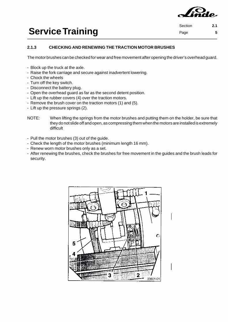
2.1.3 CHECKING AND RENEWING THE TRACTION MOTOR BRUSHES
The motor brushes can be checked for wear and free movement after opening the driver’s overhead guard.
- Block up the truck at the axle.- Raise the fork carriage and secure against inadvertent lowering.- Chock the wheels- Turn off the key switch.- Disconnect the battery plug.- Open the overhead guard as far as the second detent position.- Lift up the rubber covers (4) over the traction motors.- Remove the brush cover on the traction motors (1) and (5).- Lift up the pressure springs (2).
NOTE: When lifting the springs from the motor brushes and putting them on the holder, be sure thatthey do not slide off and open, as compressing them when the motors are installed is extremelydifficult
- Pull the motor brushes (3) out of the guide.- Check the length of the motor brushes (minimum length 16 mm).- Renew worn motor brushes only as a set.- After renewing the brushes, check the brushes for free movement in the guides and the brush leads for
security.
Service TrainingSection 2.1
Page 6
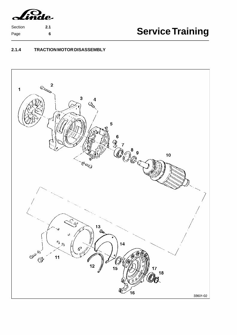
2.1.4 TRACTION MOTOR DISASSEMBLY
Service Training Page 7
Section 2.1
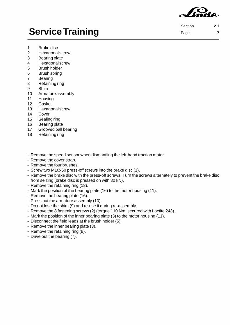
1 Brake disc2 Hexagonal screw3 Bearing plate4 Hexagonal screw5 Brush holder6 Brush spring7 Bearing8 Retaining ring9 Shim10 Armature assembly11 Housing12 Gasket13 Hexagonal screw14 Cover15 Sealing ring16 Bearing plate17 Grooved ball bearing18 Retaining ring
- Remove the speed sensor when dismantling the left-hand traction motor.- Remove the cover strap.- Remove the four brushes.- Screw two M10x50 press-off screws into the brake disc (1).- Remove the brake disc with the press-off screws. Turn the screws alternately to prevent the brake disc
from seizing (brake disc is pressed on with 30 kN).- Remove the retaining ring (18).- Mark the position of the bearing plate (16) to the motor housing (11).- Remove the bearing plate (16).- Press out the armature assembly (10).- Do not lose the shim (9) and re-use it during re-assembly.- Remove the 8 fastening screws (2) (torque 110 Nm, secured with Loctite 243).- Mark the position of the inner bearing plate (3) to the motor housing (11).- Disconnect the field leads at the brush holder (5).- Remove the inner bearing plate (3).- Remove the retaining ring (8).- Drive out the bearing (7).
Service TrainingSection 2.1
Page 8
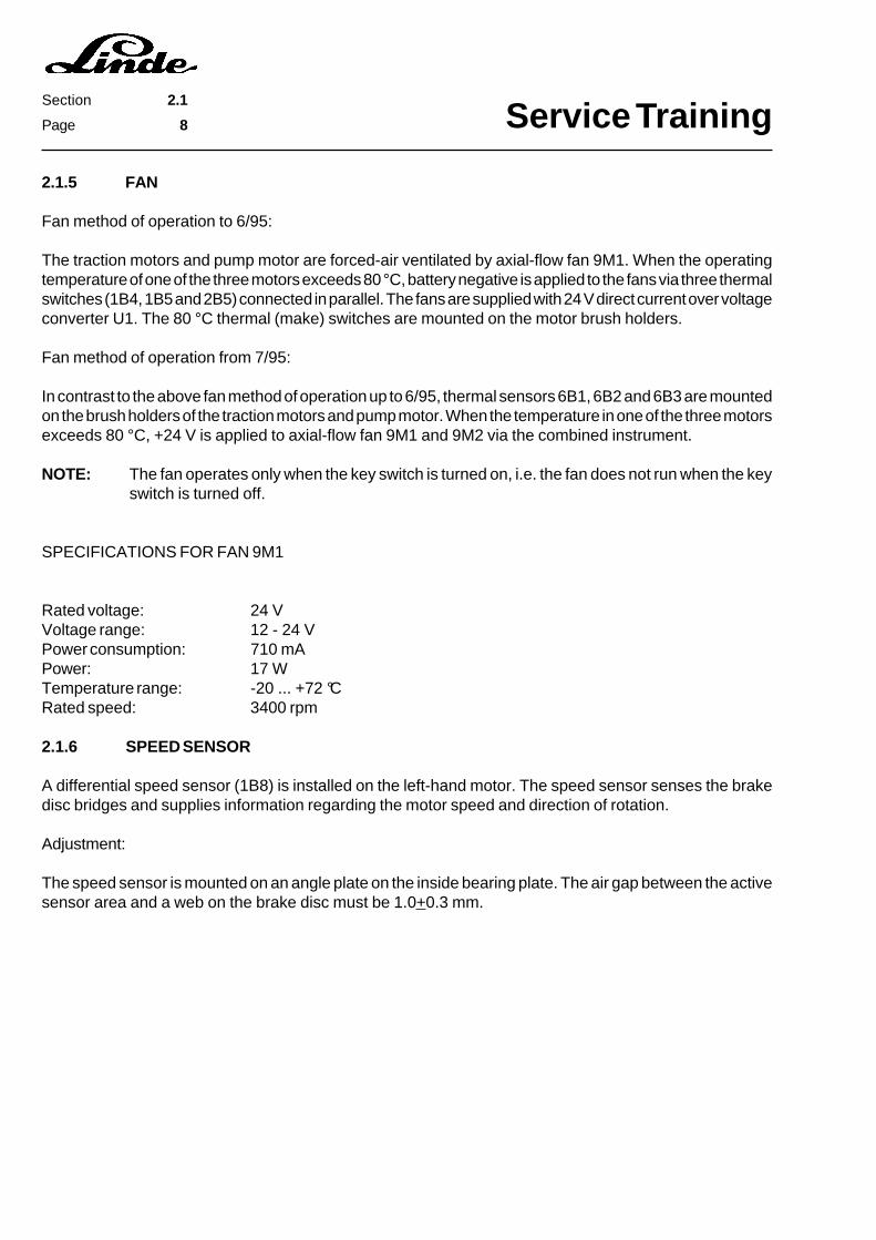
2.1.5 FAN
Fan method of operation to 6/95:
The traction motors and pump motor are forced-air ventilated by axial-flow fan 9M1. When the operatingtemperature of one of the three motors exceeds 80 °C, battery negative is applied to the fans via three thermalswitches (1B4, 1B5 and 2B5) connected in parallel. The fans are supplied with 24 V direct current over voltageconverter U1. The 80 °C thermal (make) switches are mounted on the motor brush holders.
Fan method of operation from 7/95:
In contrast to the above fan method of operation up to 6/95, thermal sensors 6B1, 6B2 and 6B3 are mountedon the brush holders of the traction motors and pump motor. When the temperature in one of the three motorsexceeds 80 °C, +24 V is applied to axial-flow fan 9M1 and 9M2 via the combined instrument.
NOTE: The fan operates only when the key switch is turned on, i.e. the fan does not run when the keyswitch is turned off.
SPECIFICATIONS FOR FAN 9M1
Rated voltage: 24 VVoltage range: 12 - 24 VPower consumption: 710 mAPower: 17 WTemperature range: -20 ... +72 °CRated speed: 3400 rpm
2.1.6 SPEED SENSOR
A differential speed sensor (1B8) is installed on the left-hand motor. The speed sensor senses the brakedisc bridges and supplies information regarding the motor speed and direction of rotation.
Adjustment:
The speed sensor is mounted on an angle plate on the inside bearing plate. The air gap between the activesensor area and a web on the brake disc must be 1.0+0.3 mm.

Service TrainingSection 2.2
Page 1
2.2 DRIVE - GEARBOX
The series 336 electric fork trucks are powered by two traction motors. The two traction wheels are drivenby two planetary hub reduction gearboxes mounted on the traction motors. The motor and the reductiongearbox together form one drive unit that is bolted to the truck chassis. For repairs, the drive axle can beremoved as a single unit.

Service TrainingSection 2.2
Page 2
2.2.1 DRIVE AXLE REMOVAL
- Remove the mast and the front wheel bolts.- Jack up and secure the truck.- Tilt the overhead guard back to the second detent.- Unscrew the wheel bolts and remove the wheels.- Loosen the locknut (3) on the parking brake lever (1) and the adjustment nut (2) on the parking brake cable
(4).- Unhook the parking brake cable (4) at the bottom of the brake shoes (5) and (6).- Remove one pin retainer (9) on each of the two brake shoes (5) and (6).- Unscrew the socket head screw (7) at the bearing plates and remove the lever (8) along with the connecting
rod (11).- Disconnect the cables at the traction motors.- Disconnect cable connectors 1X7 and 1X8 at the traction motors.- Disconnect the cable connector for the speed sensor on the left-hand traction motor.- Disconnect the cable connector for the fan.- Remove the air duct hose.- Support the drive axle with a pallet truck and blocks of wood.- Remove the eight fastening screws on each bearing plate.- Lower the drive axle.

Service TrainingSection 2.2
Page 3
Service TrainingSection 2.2
Page 4
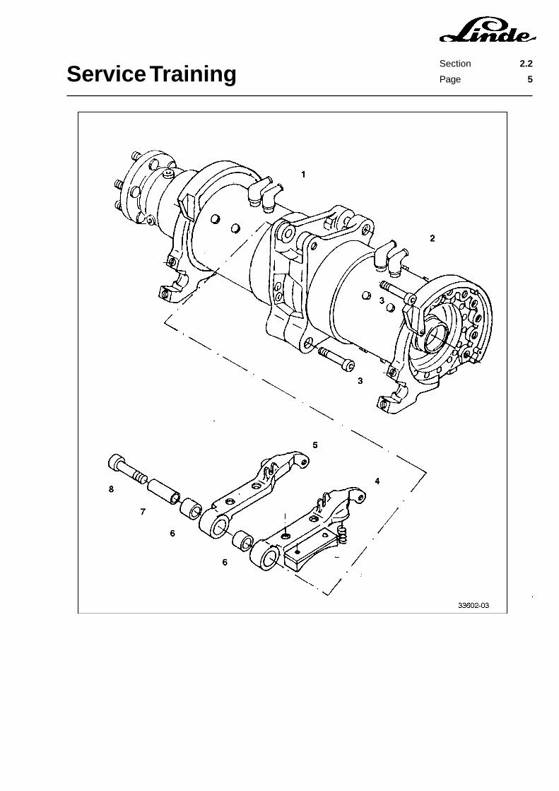
2.2.2 DRIVE AXLE DISASSEMBLY AND ASSEMBLY
Disassembly:
- Remove the motor brush cover on each traction motor.- Remove the fan along with the air duct.- Remove the two lower socket head screws (3).- Remove socket head screws (8).- Take out the brake shoes (4) and (5) with bushings (6) and (7).- Separate the two drive halves (1) and (2).
Assembly:
- Join the two drive halves (1) and (2) and bring them into alignment.- Insert the brake shoes (4) and (5) with bushings (6) and (7).- Screw in socket head screws (8).- Screw in the lower socket head screws (3).- Torque socket head screws (3) and (8) to 540 Nm.- Install the fan along with the air duct.- Fasten the motor brush cover on each traction motor.
Service TrainingSection 2.2
Page 5

Service TrainingSection 2.2
Page 6
2.2.3 PLANETARY HUB REDUCTION GEARBOX (FROM 1/95 TO 5/95)
NOTE: For design reasons, the planetary hub reduction gearbox on trucks to series 12/94 can only beexchanged as an assembly.
2.2.3.1 REMOVING THE PLANETARY HUB REDUCTION GEARBOX FROM THE TRACTIONMOTOR
- Jack up and secure the truck.- Remove the wheel nuts and wheels.- Place an oil pan underneath the gearbox.- Remove the oil filler plug (1).- Remove the oil drain plug (14) and copper sealing ring (15).- Drain the transmission oil.- Remove the 14 socket head screws (13).- Remove the planetary hub reduction gearbox from the bearing plate, taking care not to lose the O-ring (17).- Clean the sealing areas.
2.2.3.2 DISASSEMBLY OF THE PLANETARY HUB REDUCTION GEARBOX
- Remove the hexagonal head screw (6).
NOTE: The hexagon head screw (6) is self-locking and can therefore only be used once.
- Remove the two plugs (8).- Use a puller to extract the flange (10).- Put the flange (10) aside and secure it against sliding.- Insert a drift alternately into the two access holes (9) and knock the bearing inner race (12) off the flange.- Remove and renew the shaft sealing ring (11).- The O-ring (4) is accessible after pressing out the washer (7) from the flange (10).- Check and renew, if necessary, O-rings (5) and (4).
NOTE: There are shims (3) mounted between the flange (10) and washer (7). During assembly all shimsmust be installed again with the 0.5 mm shim on the profile side of the flange (10).
2.2.3.3 ASSEMBLY OF THE PLANETARY HUB REDUCTION GEARBOX
- Put the gearbox housing vertical and secure it against sliding.- Install the bearing inner race (12), making sure that it is seated evenly.- Half fill the sealing shaft ring (11) with grease and drive it into the housing (2).- Install the shims (3) in the flange (10).- Position the O-ring (5) on the washer (7) and secure it with grease.- Press the washer (7) and O-ring (4) into the flange (10).- Position the flange (10) and washer (7) on the planetary hub reduction gearbox (18), taking care not to
damage the teeth.- Install the hexagon head screw (6) through the washer (7) and carefully tighten it to seat the flange (10)
and washer (7) correctly (torque to 810 Nm).- Install the 2 plugs (8) in the flange (10) (torque to 20 Nm).
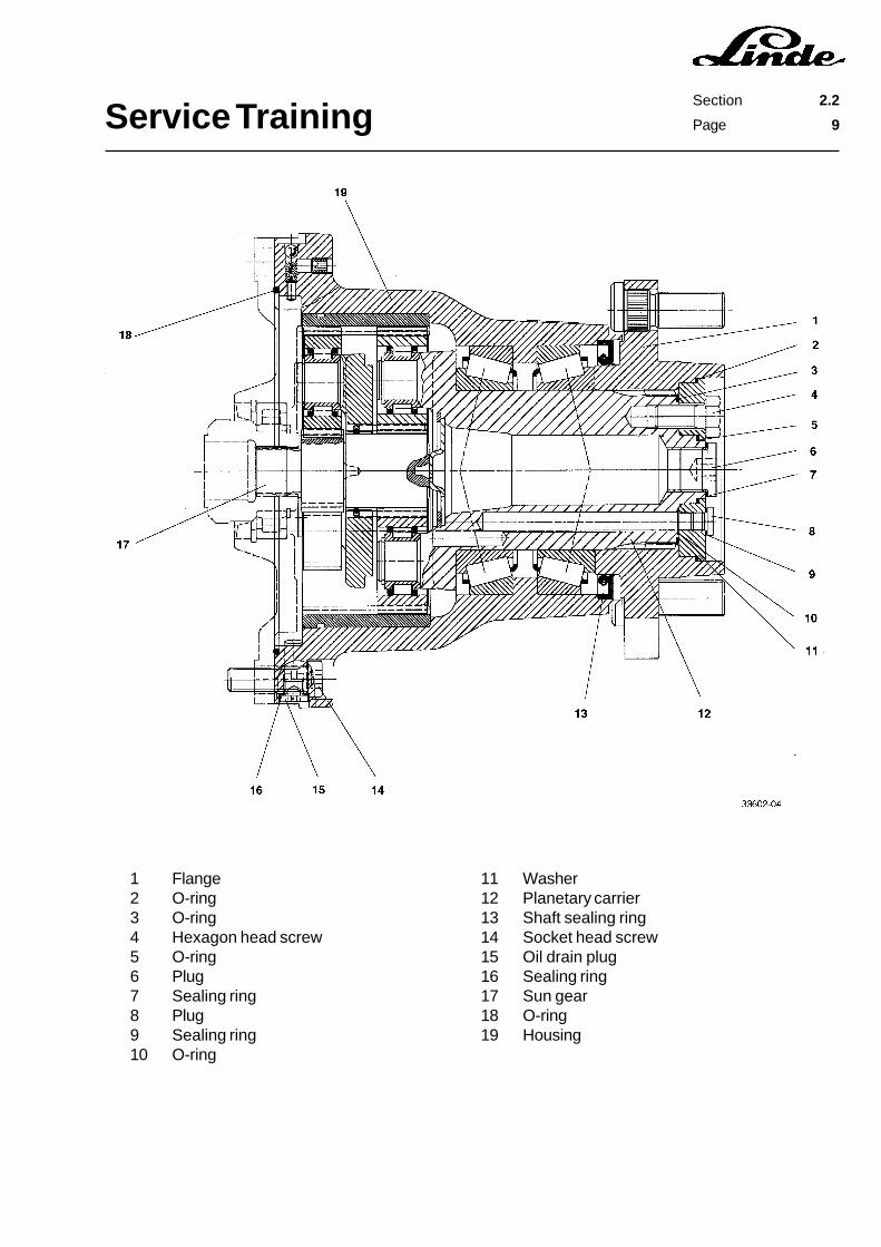
Service TrainingSection 2.2
Page 7
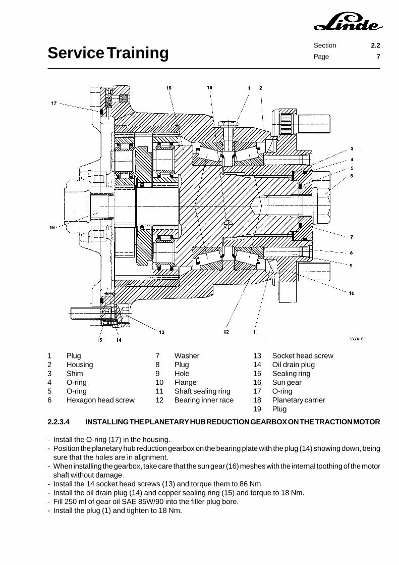
1 Plug2 Housing3 Shim4 O-ring5 O-ring6 Hexagon head screw
7 Washer8 Plug9 Hole10 Flange11 Shaft sealing ring12 Bearing inner race
13 Socket head screw14 Oil drain plug15 Sealing ring16 Sun gear17 O-ring18 Planetary carrier19 Plug
2.2.3.4 INSTALLING THE PLANETARY HUB REDUCTION GEARBOX ON THE TRACTION MOTOR
- Install the O-ring (17) in the housing.- Position the planetary hub reduction gearbox on the bearing plate with the plug (14) showing down, being
sure that the holes are in alignment.- When installing the gearbox, take care that the sun gear (16) meshes with the internal toothing of the motor
shaft without damage.- Install the 14 socket head screws (13) and torque them to 86 Nm.- Install the oil drain plug (14) and copper sealing ring (15) and torque to 18 Nm.- Fill 250 ml of gear oil SAE 85W/90 into the filler plug bore.- Install the plug (1) and tighten to 18 Nm.

Service TrainingSection 2.2
Page 8
2.2.4 PLANETARY HUB REDUCTION GEARBOX (FROM SERIES 6/95)
2.2.4.1 REMOVING THE PLANETARY HUB REDUCTION GEARBOX FROM THE TRACTIONMOTOR
- Jack up and secure the truck.- Remove the wheel nuts and wheels.- Place an oil pan underneath the gearbox.- Remove the oil filler plug (6) and copper sealing ring (7).- Remove the oil drain plug (15) and copper sealing ring (16).- Drain the transmission oil.- Remove plug (8)- Remove the 14 socket head screws (14).- Remove the planetary hub reduction gearbox from the bearing plate, taking care not to lose the O-ring (18).- Clean the sealing areas.
2.2.4.2 DISASSEMBLY OF THE PLANETARY HUB REDUCTION GEARBOX
- Remove the four hexagonal head screws (4).- Use a puller to extract the flange (1),- Paying attention to the O-rings (3), (5) and (10).- O-ring (2) is accessible after pressing the washer (11) out of the flange (1).- If necessary, remove and renew the shaft sealing ring (13).
2.2.4.3 ASSEMBLY OF THE PLANETARY HUB REDUCTION GEARBOX
- Half fill the sealing shaft ring (13) with grease and drive it into the housing (19).- Position the O-rings (3), (5) and (10) on the planetary carrier (12) and secure it with grease.- Carefully slide the flange (1) onto the planetary carrier (12), taking care not to damage the toothing.- Hit the washer (11) and O-ring (2) into the flange, making sure that the holes are in alignment.- Install the four hexagon head screws (4) and torque to 110 Nm.
2.2.4.4 MOUNTING THE PLANETARY HUB REDUCTION GEARBOX ON THE TRACTION MOTOR
- Install the O-ring (18) into the housing.- Position the planetary hub reduction gearbox on the bearing plate with the oil drain plug opening showing
down, being sure that the holes are in alignment.- When installing the gearbox, take care that the sun gear (17) meshes with the internal toothing of the motor
shaft without damaging it.- Install the 14 socket head screws (13) and torque to 86 Nm.- Install the oil drain plug (15) and copper sealing ring (16) and torque to 18 Nm.- Fill 250 ml of gear oil SAE 85W/90 into the filler plug bore.
NOTE: The oil level must reach the lower edge of the threaded bore for plug (8).
- Install the plug (8) and sealing ring (9), and torque to 18 Nm.- Install the oil filler plug (6) and copper sealing ring (7), and torque to 102 Nm.
Service TrainingSection 2.2
Page 9
1 Flange2 O-ring3 O-ring4 Hexagon head screw5 O-ring6 Plug7 Sealing ring8 Plug9 Sealing ring10 O-ring
11 Washer12 Planetary carrier13 Shaft sealing ring14 Socket head screw15 Oil drain plug16 Sealing ring17 Sun gear18 O-ring19 Housing
Service TrainingSection 2.2
Page 10
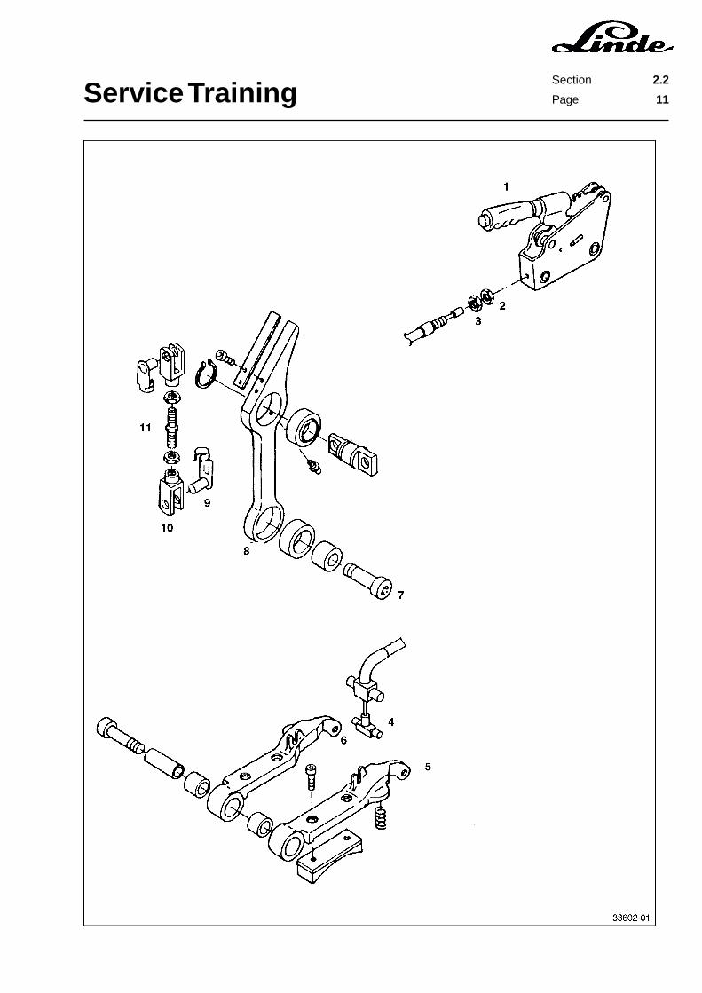
2.2.5 DRIVE AXLE INSTALLATION
- Move the pre-assembled drive axle with a pallet truck into the truck.- Raise the axle until the bearing plate socket head screws can be inserted.- Tighten 8 socket head screws each on the bearing plates and torque them to 600 Nm.- Mount the lever (8) and the connecting rod (11) and fasten them to the bearing plates with screw (7).- Check the brake levers for ease of movement.- Insert the bolt with cotter (9) on the two brake shoes (5) and (6).- Hook the parking brake cable (4) to the brake shoes (5) and (6).- Adjust the parking brake cable (4) with the nut (2) and tighten the locknut (3).- Mount the hose on the air duct.- Connect the cable connector to the fan.- Connect the cable connector to the speed sensor at the left-hand traction motor.- Connect the traction motor cables.- Check the oil level in the wheel drive gearbox, adding SAE 85W / 90 transmission oil, if needed.- Mount the wheels and torque the wheel bolts to 460 Nm.
Service TrainingSection 2.2
Page 11

Service TrainingSection 2.2
Page 12

Service TrainingSection 2.3
Page 1
2.3 CHASSIS
The series 336 fork trucks are available for various load capacities.
Type Standard Version Higher Seat Version Load Capacity
E 20 400 Ah 480 Ah 2.0 tE 25 500 Ah 600 Ah 2.5 tE 30 500 Ah 600 Ah 3.0 t
The standard versions of the trucks can be used with containers. With the option “higher driver’s seat”,batteries with a higher capacity rating can be used.
2.3.1 SEAT SWITCH
Method of operation to series 6/95:
A seat switch is installed in the driver’s seat, which activates timer 1A3 when actuated. In order to preventa faulty operation of the switch on uneven roadways, the timer cuts off the enable signal for the traction andlift control after a delay of approx. 2 seconds when the seat switch is no longer actuated.Timer 1A3 is mounted opposite the voltage converter on the contactor board. The timer is connected to themain cable harness via a 8-pin connector.
Method of operation from series 7/95:
The timer 1A3 has been omitted on trucks built since 7/95. The travel control time delay is integrated intothe electronic travel unit 1A2. Starting with this series, the working hydraulics can be operated without theseat switch having to be activated.

Service TrainingPage 2
Section 2.3
2.3.1.1 RENEWING THE SEAT SWITCH
- Pull out the lower fastener on the driver’s seat gaiter.- Push the gaiter up.- Remove the socket head screw (2) and washer (1).- Renew the microscwitch (9) after disconnecting the cable tie (5).
1 Washer2 Socket head screw3 Holding plug4 Holding plug5 Cable tie6 Cable connector7 Base plate8 Bracket9 Microswitch

Service TrainingSection 2.3
Page 3
2.3.2 CABIN
The cabin can be tilted back completely. The first detent position is at an opening angle of 35°. This positionis used for charging the battery. For changing the battery, the cabin can be held at an opening angle of 100degrees.
The cabin is available in various versions.
Model Version
1 Overhead guard only
2 Overhead guard + roof pane
3 Overhead guard + roof pane + front windscreen with wiper and washer
4 Overhead guard + roof pane + front windscreen with wiper and washer + rearwindscreen with wiper and washer
5 Overhead guard + roof pane + front windscreen with wiper and washer + rearwindscreen with wiper and washer + doors
2.3.2.1 TORSION BAR SPRINGS
A torsion bar spring pack is located in the articulated area of the cabin. This spring pack twists when the cabinis closed. The mass energy of the cabin is thus stored in the springs, allowing easy opening of the cabin.A gas-filled shock-absorber prevents the cabin from closing too fast.
Depending on the cab version, the correct number of springs and washers and the right type of fishplatesmust be chosen.
The correct combination can be determined with the following table.
Model Spring (6 mm) Spring (4 mm) Washers Fishplates
1 4 items ------ 4 items 30 mm2 4 items ------ 4 items 30 mm3 5 items ------ ------ 30 mm4 5 items ------ ------ 30 mm5 6 items 2 items ------ 20 mm
Service TrainingPage 4
Section 2.3
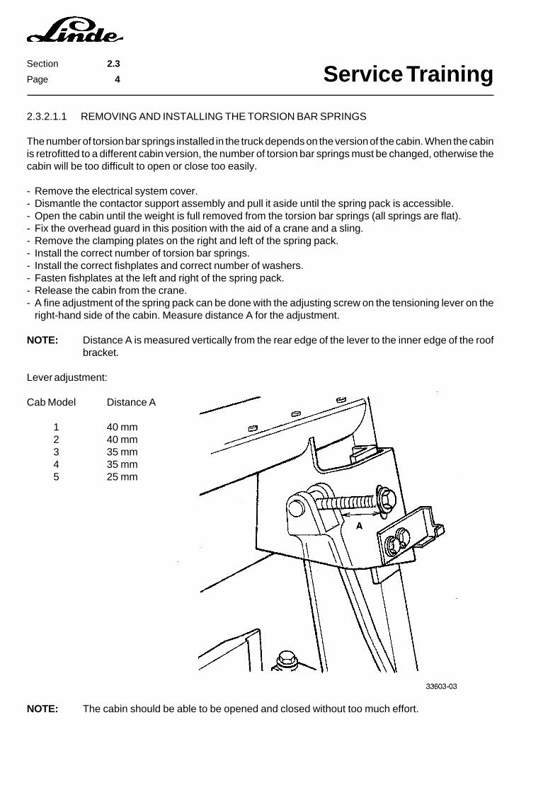
2.3.2.1.1 REMOVING AND INSTALLING THE TORSION BAR SPRINGS
The number of torsion bar springs installed in the truck depends on the version of the cabin. When the cabinis retrofitted to a different cabin version, the number of torsion bar springs must be changed, otherwise thecabin will be too difficult to open or close too easily.
- Remove the electrical system cover.- Dismantle the contactor support assembly and pull it aside until the spring pack is accessible.- Open the cabin until the weight is full removed from the torsion bar springs (all springs are flat).- Fix the overhead guard in this position with the aid of a crane and a sling.- Remove the clamping plates on the right and left of the spring pack.- Install the correct number of torsion bar springs.- Install the correct fishplates and correct number of washers.- Fasten fishplates at the left and right of the spring pack.- Release the cabin from the crane.- A fine adjustment of the spring pack can be done with the adjusting screw on the tensioning lever on the
right-hand side of the cabin. Measure distance A for the adjustment.
NOTE: Distance A is measured vertically from the rear edge of the lever to the inner edge of the roofbracket.
Lever adjustment:
Cab Model Distance A
1 40 mm2 40 mm3 35 mm4 35 mm5 25 mm
NOTE: The cabin should be able to be opened and closed without too much effort.

Service TrainingSection 2.4
Page 1
2.4 STEERING SYSTEM

Service TrainingSection 2.4
Page 2
2.4.1 STEERING AXLE
The Linde combined steering axle has all the advantages of the close-coupled wheel axle and the swingaxle:
- large swing for good driving comfort- small turning radius, narrow aisle width- good curve stability- minimal tipping- steering cylinder mounted in the counterweight for all-round protection.
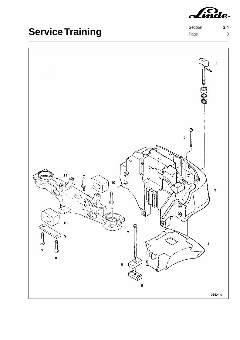
2.4.1.1 STEERING AXLE REMOVAL
- A second person and a fork truck are required for the removal of the additional weight and the steeringaxle.
- Remove the battery.- Remove the wheel bolts.- Jack up the rear of the truck at least 350 mm.- Secure the front wheels against rolling with chocks.- Remove the rear wheels.- Open the overhead guard to the second detent.- Disconnect cable connectors X6 and X7 to the proximity switches.- Place an oil pan underneath the truck.- Disconnect the two hydraulic hoses to the steering cylinder at the pipes.
NOTE: Trucks without the optional “higher driver’s seat” have an additional weight on thecounterweight. This weight must be removed before the removal of the steeringaxle, otherwise the truck must be raised too high due to the large height of thesteering axle.
- Place a support under the additional weight (4).- Loosen the fastening bolt (7) on the additional weight in the battery compartment.- Take out the trailer coupling pin (1).- Remove the second additional weight fastening bolt (2) from the additional weight (4) through the hole for
the trailer coupling pin.
NOTE: On trucks from series 10/94, the mounting bolt (2) can be accessed from below at the ballastweight (4).
- Slowly lower the additional weight.- Support the steering axle (11).- Remove the steering axle fastening bolts (8).- Remove the support piece by piece to slowly lower the steering axle.
Service TrainingSection 2.4
Page 3
Service TrainingSection 2.4
Page 4
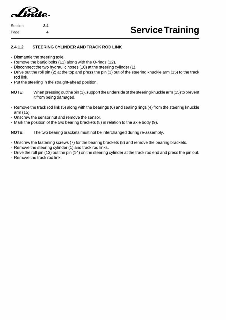
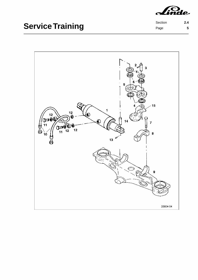
2.4.1.2 STEERING CYLINDER AND TRACK ROD LINK
- Dismantle the steering axle.- Remove the banjo bolts (11) along with the O-rings (12).- Disconnect the two hydraulic hoses (10) at the steering cylinder (1).- Drive out the roll pin (2) at the top and press the pin (3) out of the steering knuckle arm (15) to the track
rod link.- Put the steering in the straight-ahead position.
NOTE: When pressing out the pin (3), support the underside of the steering knuckle arm (15) to preventit from being damaged.
- Remove the track rod link (5) along with the bearings (6) and sealing rings (4) from the steering knucklearm (15).
- Unscrew the sensor nut and remove the sensor.- Mark the position of the two bearing brackets (8) in relation to the axle body (9).
NOTE: The two bearing brackets must not be interchanged during re-assembly.
- Unscrew the fastening screws (7) for the bearing brackets (8) and remove the bearing brackets.- Remove the steering cylinder (1) and track rod links.- Drive the roll pin (13) out the pin (14) on the steering cylinder at the track rod end and press the pin out.- Remove the track rod link.
Service TrainingSection 2.4
Page 5
Service TrainingSection 2.4
Page 6
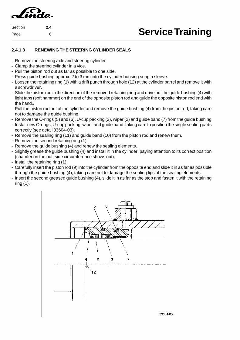
2.4.1.3 RENEWING THE STEERING CYLINDER SEALS
- Remove the steering axle and steering cylinder.- Clamp the steering cylinder in a vice.- Pull the piston rod out as far as possible to one side.- Press guide bushing approx. 2 to 3 mm into the cylinder housing sung a sleeve.- Loosen the retaining ring (1) with a drift punch through hole (12) at the cylinder barrel and remove it with
a screwdriver.- Slide the piston rod in the direction of the removed retaining ring and drive out the guide bushing (4) with
light taps (soft hammer) on the end of the opposite piston rod and guide the opposite piston rod end withthe hand..
- Pull the piston rod out of the cylinder and remove the guide bushing (4) from the piston rod, taking carenot to damage the guide bushing.
- Remove the O-rings (5) and (6), U-cup packing (3), wiper (2) and guide band (7) from the guide bushing- Install new O-rings, U-cup packing, wiper and guide band, taking care to position the single sealing parts
correctly (see detail 33604-03).- Remove the sealing ring (11) and guide band (10) from the piston rod and renew them.- Remove the second retaining ring (1).- Remove the guide bushing (4) and renew the sealing elements.- Slightly grease the guide bushing (4) and install it in the cylinder, paying attention to its correct position
(chamfer on the out, side circumference shows out).- Install the retaining ring (1).- Carefully insert the piston rod (9) into the cylinder from the opposite end and slide it in as far as possible
through the guide bushing (4), taking care not to damage the sealing lips of the sealing elements.- Insert the second greased guide bushing (4), slide it in as far as the stop and fasten it with the retaining
ring (1).
Service TrainingSection 2.4
Page 7
Service TrainingSection 2.4
Page 8
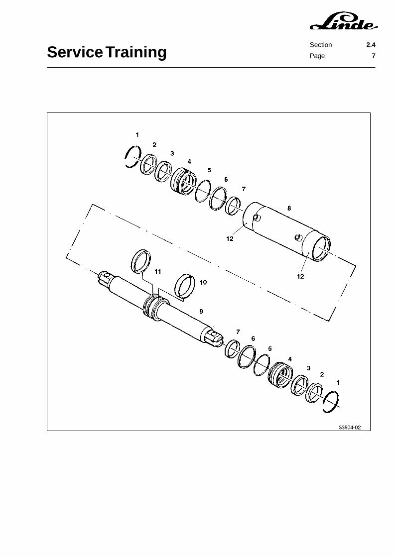
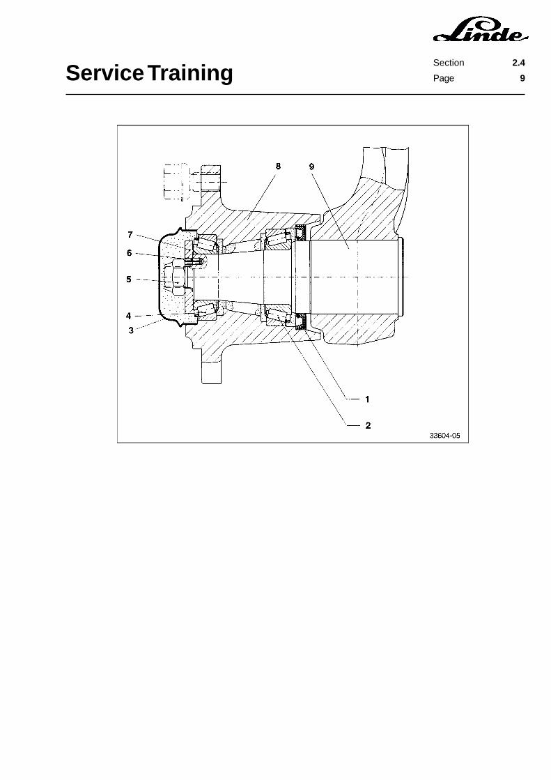
2.4.1.4 RENEWING THE WHEEL HUB TAPERED ROLLER BEARINGS AND SHAFT SEALINGRING
- Jack up the truck and secure it.- Remove the wheel.- Remove the wheel hub (3).- Loosen and remove the retaining nut (5).- Remove the washer (7) and the roll pin (6).- Drive out the wheel hub (8) from the inside out using a soft hammer. Do not let the inner race of the tapered
roller bearing (4) fall out.- Take the shaft sealing ring (1) out of the hub (8).- Take the inner race of the tapered roller bearing (2) out of the wheel hub.- Take the outer races of the tapered roller bearings (2) and (4) out of the wheel hub (8).- Install the outer races of the new tapered roller bearings (2) and (4) in the wheel hub (8).
NOTE: Be sure that the bearings are properly positioned.
- Fill the space around the tapered roller bearing (2) with Linde heavy duty grease.- Grease the inner races of the tapered roller bearing (2) well and install carefully on the outer race.- Fill the inside of the new shaft sealing ring (1) with Linde heavy duty grease and install it in the wheel hub
in the correct position (sealing lip showing inside).- Slide the wheel hub onto the wheel shaft, taking care not to damage the shaft sealing ring (1) and that the
inner race of the tapered roller bearing (2) does not stick.- Fill the space around the tapered roller bearing (4) with Linde heavy duty grease.- Grease the inner races of the tapered roller bearing (4) well and install carefully on the wheel shaft.- Slide the washer (7) onto the wheel shaft and drive in the cotter pin (6).- Install a new retaining nut (5) and tighten it with a torque of 210 Nm.- Fill the wheel cap (3) fully with Linde heavy duty grease, position the cap and drive it in place with a soft
hammer.
Service TrainingSection 2.4
Page 9

Service TrainingSection 2.4
Page 10
2.4.1.5 RENEWING THE AXLE BODY TAPERED ROLLER BEARINGS AND WIPERS
- Remove the steering axle.- Remove the steering cylinder.- Remove wheel hub (on E 25 / 30 only).- Turn the steering axle so that the steering knuckles show, and secure it against turning.- Slacken the retaining screw (7) for the steering knuckle arm (1) and unscrew it about 2 mm.- Loosen the steering knuckle arm by tapping on the retaining screw (7).- Unscrew the retaining screw a few millimetres several times and remove the steering knuckle arm from
the axle body by tapping on the retaining screw.- Remove the retaining screw (7) and the steering knuckle arm (1).
NOTE: The steering axle of the E 20 truck has two retaining screws for securing the steering knucklearm. Loosen both retaining screws equally to prevent the steering knuckle arm from seizing.
- Pull out the axle body (8) upwards.- Remove wiper (2), taking care that the inner race of the tapered roller bearing (3) does not fall out.- Remove wiper (6) and the inner race of the tapered roller bearing (5).- Extract both outer races of the tapered roller bearing (3) and (5).
NOTE: When installing the tapered roller bearings, make sure that the outer and inner races of the twobearings are not interchanged.
- Drive new outer races into the axle centre.- Fill the space around the bearing completely with lithium-based grease.- Grease the inner race of the tapered roller bearing (5) well and install it.- Fill wiper (6) well with grease and drive it into the centre axle body with the aid of special tool part no. 000
941 9721.- Carefully install the axle body (8) in the centre axle body (4).- Grease the inner race of the tapered roller bearing (3) well and install it.- Fill wiper (2) well with grease and drive it into the centre axle body (4) with the aid of special tool part no.
000 941 9721.
NOTE: The top edge on the steel ring of wiper (2) must be flush with the face (9) of the centre axle (4).
Detail X:

Service TrainingSection 2.4
Page 11
- Install the steering knuckle arm (1) and insert the retaining screw (7).- At first torque the retaining screw (7) only to 120 - 150 Nm so that the rollers in the tapered roller bearings
can come into alignment.- Move the axle body through the full swivel range several times so that the rollers in the tapered roller
bearings can become aligned.- Tighten the retaining screw (7) to the full torque of 1100 Nm.
NOTE: The steering axle of the E 20 truck has two retaining screws, each of which must be torquedto 295 Nm.
Service TrainingSection 2.4
Page 12
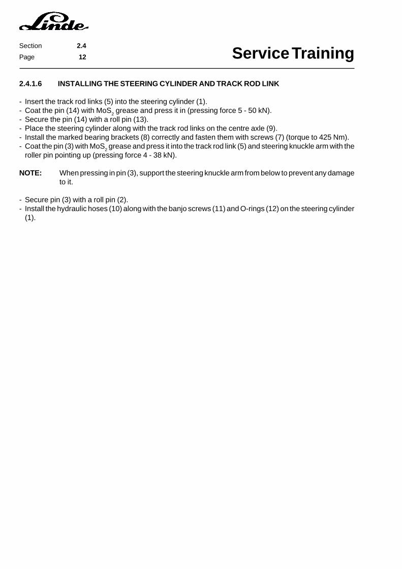
2.4.1.6 INSTALLING THE STEERING CYLINDER AND TRACK ROD LINK
- Insert the track rod links (5) into the steering cylinder (1).- Coat the pin (14) with MoS
2 grease and press it in (pressing force 5 - 50 kN).
- Secure the pin (14) with a roll pin (13).- Place the steering cylinder along with the track rod links on the centre axle (9).- Install the marked bearing brackets (8) correctly and fasten them with screws (7) (torque to 425 Nm).- Coat the pin (3) with MoS
2 grease and press it into the track rod link (5) and steering knuckle arm with the
roller pin pointing up (pressing force 4 - 38 kN).
NOTE: When pressing in pin (3), support the steering knuckle arm from below to prevent any damageto it.
- Secure pin (3) with a roll pin (2).- Install the hydraulic hoses (10) along with the banjo screws (11) and O-rings (12) on the steering cylinder
(1).

Service TrainingSection 2.4
Page 13

Service TrainingSection 2.4
Page 14
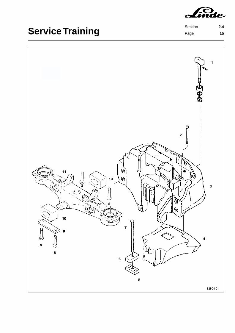
2.4.1.7 INSTALLING THE STEERING AXLE
- Put two rubber axle blocks (10) on the centre axle.- Install the steering axle (11) with the axle blocks (10) in the counterweight (3) from below, raise it slightly
until the axle blocks contact the counterweight and safely support it.- Lead both hydraulic hoses through the counterweight into the battery compartment.- Lead the steering sensor cables into the counterweight.- Coat the steering fastening screws (8) with Loctite 243.- Secure the two plates (9) and rubber axle mounts (10) with the screws (8).- Torque the screws (8) to 195 Nm.- On trucks without the higher driver’s seat, install the additional weight (4) in the counterweight from below
and safely support it.- Install the first fastening screw (2) through the hole for the trailer coupling pin.
NOTE: On trucks from series 10/94, the mounting bolt (2) can be accessed from below at the ballastweight (4).
- Install the second fastening screw (7) along with the plate (6).- Tighten both screws.- Connect the two steering cylinder hose lines to the appropriate pipelines.- Connect the proximity switch connectors X6 and X7.- Install the battery.- Eliminate any air in the steering by operating the steering wheel through 10 complete travel cycles.- Check the oil level in the oil reservoir and add oil, if necessary.- Remount the wheels.- Lower the truck to the ground.- Torque opposite wheel bolts to 180 Nm.
Service TrainingSection 2.4
Page 15
Service TrainingSection 2.4
Page 16
2.4.2 POWER STEERING CONTROL VALVE
The power steering control valve is mounted under the front cross member of the frame. At the end of thesteering wheel shaft is a taper with a pin. When the overhead guard is lowered, the steering column isconnected mechanically to the steering shaft through the internal gear coupling that engages in the taper,i.e. in the pin.
The power steering control valve itself is essentially a rotor pump and a control valve built together into oneunit. The rotor pump is a gear-type pump that meters the hydraulic oil flow from the working hydraulic systemin accordance with the rotation of the steering wheel.
The steering control valve consists of the steering housing with the valve bore and the spool that can be turnedand moved axially in the bore. The axial movement of the spool modulates the working pressure and thereversal of the oil flow depending upon the steering wheel direction of rotation.
The spool has a groove into which a pin engages. The pin is lifted and it engages in a sleeve with an annularmagnet when the steering wheel is operated and the spool is moving. This arrangement is used to controla reed switch.
The reed switch allows a signal to go to the working hydraulic system electronics, which lets the pump motorrun at 600 rpm as soon as the steering wheel is operated.

Service TrainingSection 2.5
Page 1
2.5 CONTROLS
2.5.1 TRAVEL CONTROL
The travel control pedals are integrated in the overhead guard. Two different types of pedal group modelsare available:
Double-pedal modelSingle-pedal model
The truck is braked either mechanically (brake pedal) or electrically (regenerative braking and plug braking).
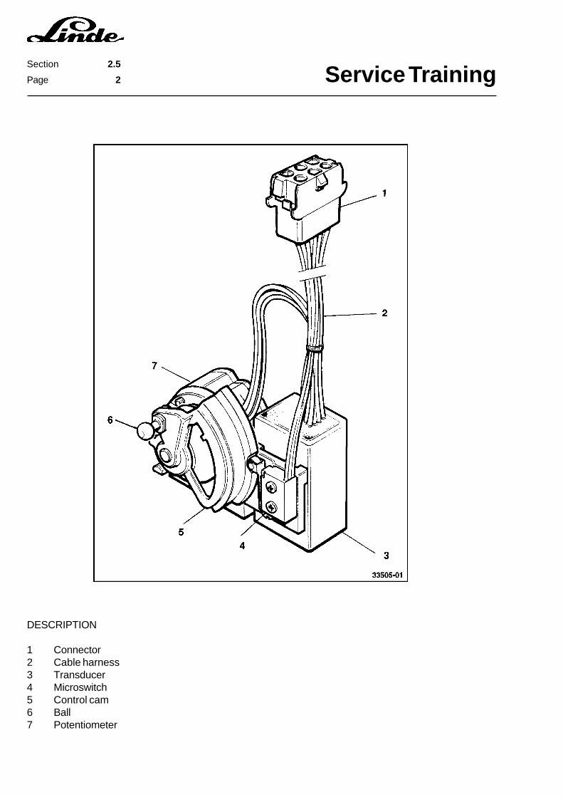
2.5.1.1 ACCELERATOR SENSOR
The accelerator sensor is mounted under the overhead guard and connected to the pedals by means of anadjustable linkage. The accelerator sensor microswitch is actuated by a control cam when travelling forwardor reverse.
A conductive plastic potentiometer connected to the moveable control cam is fitted to the accelerator sensor.The potentiometer has a built-in return spring, which moves the potentiometer and the control cam to a safeposition when the linkage rod is disconnected. In this position the microswitch turns the directional contactorsoff.
The change in resistance in the potentiometer is converted by the transducer, which is also mounted on theaccelerator sensor, into a set-point signal directly proportional to the position of the pedal. The acceleratorsensor itself can not be adjusted.
When connector 1X10 is not plugged in, the control is inoperative and the directional contactors cannot make.
Service TrainingSection 2.5
Page 2
DESCRIPTION
1 Connector2 Cable harness3 Transducer4 Microswitch5 Control cam6 Ball7 Potentiometer
Service TrainingSection 2.5
Page 3
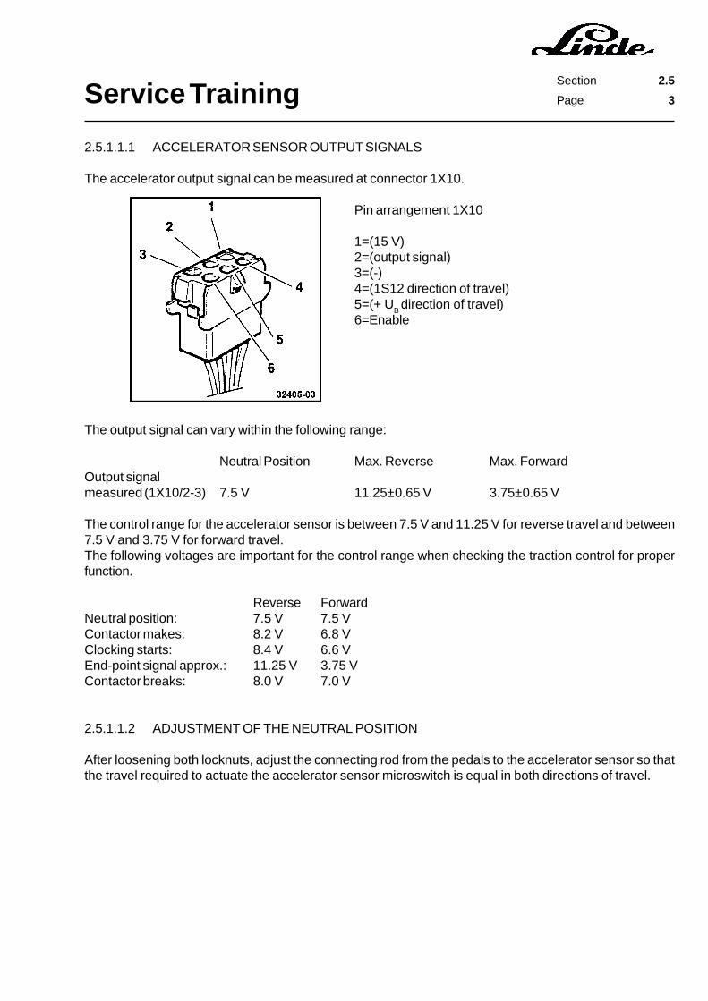
2.5.1.1.1 ACCELERATOR SENSOR OUTPUT SIGNALS
The accelerator output signal can be measured at connector 1X10.
Pin arrangement 1X10
1=(15 V)2=(output signal)3=(-)4=(1S12 direction of travel)5=(+ U
B direction of travel)
6=Enable
The output signal can vary within the following range:
Neutral Position Max. Reverse Max. ForwardOutput signalmeasured (1X10/2-3) 7.5 V 11.25±0.65 V 3.75±0.65 V
The control range for the accelerator sensor is between 7.5 V and 11.25 V for reverse travel and between7.5 V and 3.75 V for forward travel.The following voltages are important for the control range when checking the traction control for properfunction.
Reverse ForwardNeutral position: 7.5 V 7.5 VContactor makes: 8.2 V 6.8 VClocking starts: 8.4 V 6.6 VEnd-point signal approx.: 11.25 V 3.75 VContactor breaks: 8.0 V 7.0 V
2.5.1.1.2 ADJUSTMENT OF THE NEUTRAL POSITION
After loosening both locknuts, adjust the connecting rod from the pedals to the accelerator sensor so thatthe travel required to actuate the accelerator sensor microswitch is equal in both directions of travel.
Service TrainingSection 2.5
Page 4
2.5.2 BRAKING
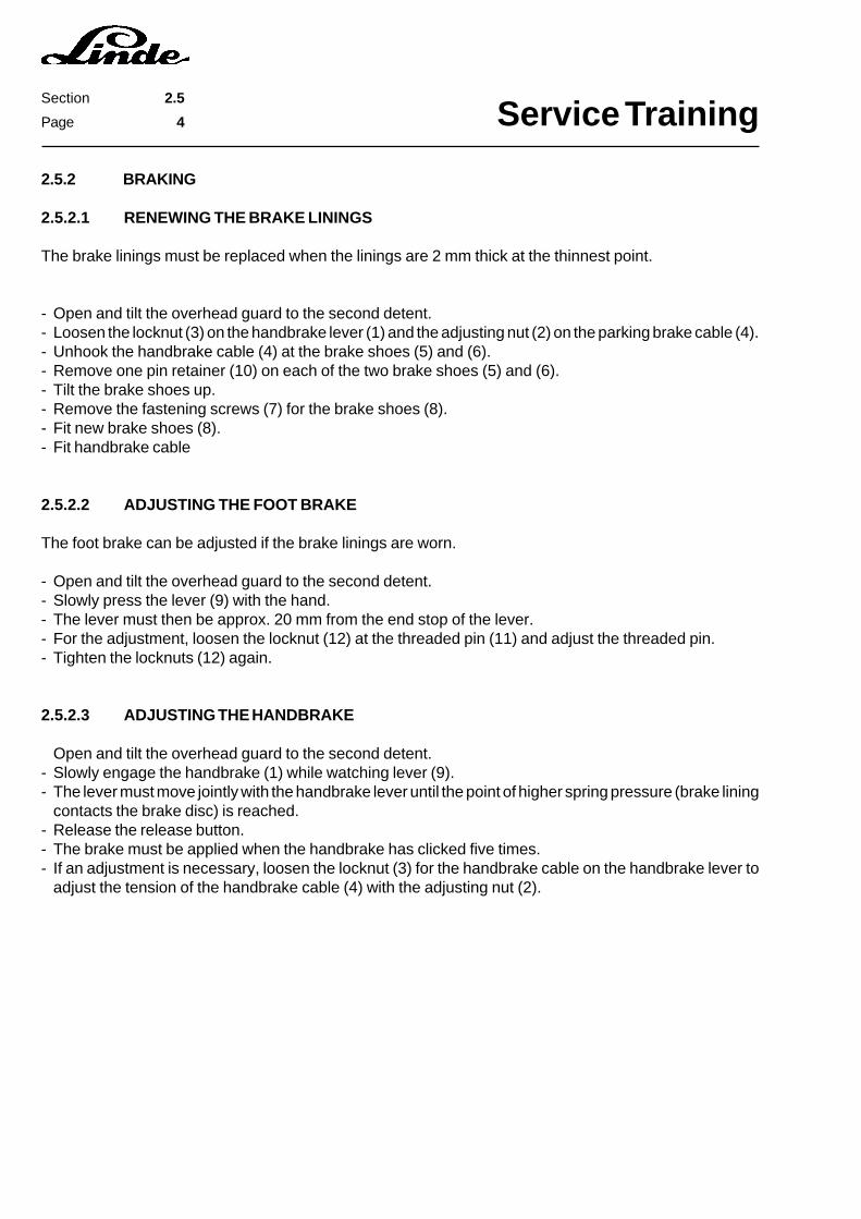
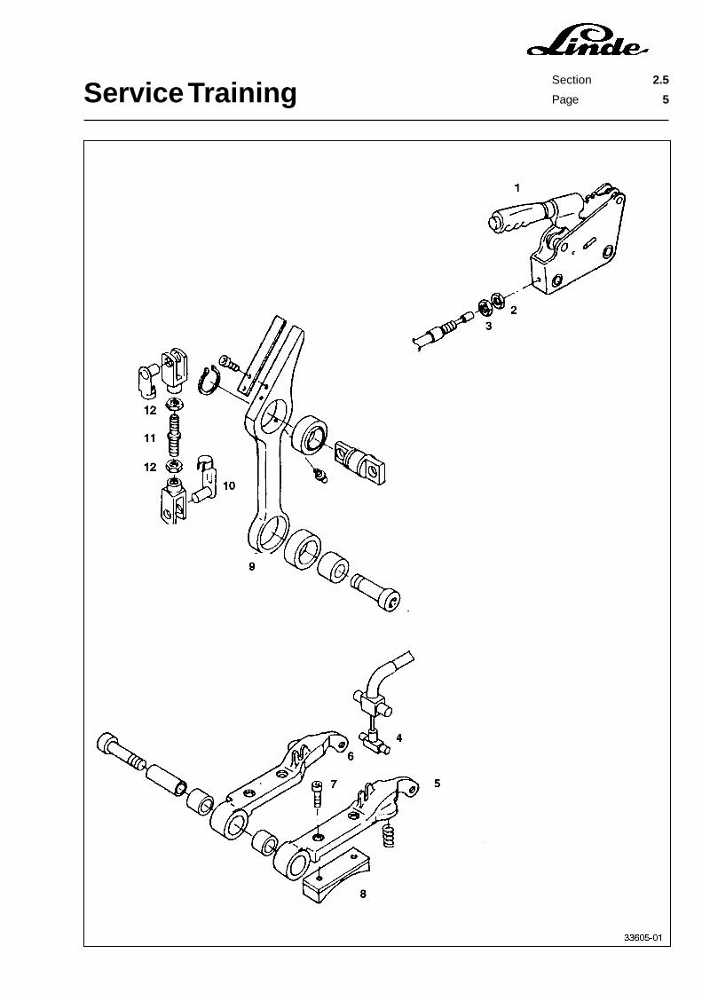
2.5.2.1 RENEWING THE BRAKE LININGS
The brake linings must be replaced when the linings are 2 mm thick at the thinnest point.
- Open and tilt the overhead guard to the second detent.- Loosen the locknut (3) on the handbrake lever (1) and the adjusting nut (2) on the parking brake cable (4).- Unhook the handbrake cable (4) at the brake shoes (5) and (6).- Remove one pin retainer (10) on each of the two brake shoes (5) and (6).- Tilt the brake shoes up.- Remove the fastening screws (7) for the brake shoes (8).- Fit new brake shoes (8).- Fit handbrake cable
2.5.2.2 ADJUSTING THE FOOT BRAKE
The foot brake can be adjusted if the brake linings are worn.
- Open and tilt the overhead guard to the second detent.- Slowly press the lever (9) with the hand.- The lever must then be approx. 20 mm from the end stop of the lever.- For the adjustment, loosen the locknut (12) at the threaded pin (11) and adjust the threaded pin.- Tighten the locknuts (12) again.
2.5.2.3 ADJUSTING THE HANDBRAKE
Open and tilt the overhead guard to the second detent.- Slowly engage the handbrake (1) while watching lever (9).- The lever must move jointly with the handbrake lever until the point of higher spring pressure (brake lining
contacts the brake disc) is reached.- Release the release button.- The brake must be applied when the handbrake has clicked five times.- If an adjustment is necessary, loosen the locknut (3) for the handbrake cable on the handbrake lever to
adjust the tension of the handbrake cable (4) with the adjusting nut (2).
Service TrainingSection 2.5
Page 5

Service TrainingSection 2.5
Page 6

Service TrainingSection 2.6
Page 1
2.6 ELECTRICAL SYSTEM
The series 336 trucks are equipped with a compact LTM control for the travel drive and the working hydraulicsystem. The steering system is controlled via the lift LTM control.The compact LTM control has the following advantages over the previous LTM control:
- less space required- easier installation- available as replacement part- integrated freewheel diode- integrated brake diode- integrated regenerative braking diode- easier troubleshooting- improved dissipation of heat
Features of the power unit:
- N-type channel enhancement type MOSFET- Zener diode for active overvoltage protection- gate-source Zener diode and resistor against static overvoltage at the gate- integrated gate resistors against internal oscillations- insulated aluminium base plate- longer air gaps
Regenerative braking is standard equipment for this series, which returns part of the energy generated duringbraking back to the battery. The control unit and the fan are supplied with 24 V direct current via a separatevoltage converter.
Trucks equipped with optional lighting require a separate voltage converter.
Service TrainingSection 2.6
Page 2
2.6.1 COMPACT POWER MODULE
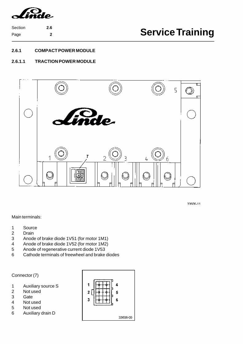
2.6.1.1 TRACTION POWER MODULE
Main terminals:
1 Source2 Drain3 Anode of brake diode 1V51 (for motor 1M1)4 Anode of brake diode 1V52 (for motor 1M2)5 Anode of regenerative current diode 1V536 Cathode terminals of freewheel and brake diodes
Connector (7)
1 Auxiliary source S2 Not used3 Gate4 Not used5 Not used6 Auxiliary drain D
Service TrainingSection 2.6
Page 3
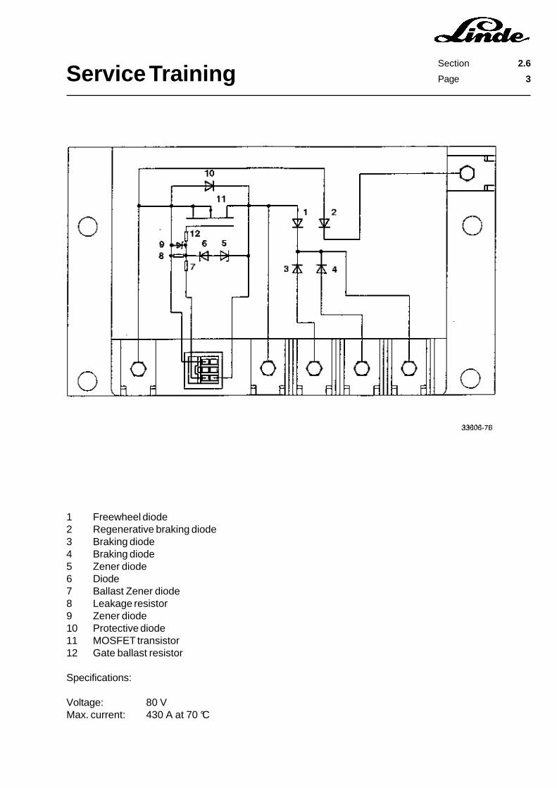
1 Freewheel diode2 Regenerative braking diode3 Braking diode4 Braking diode5 Zener diode6 Diode7 Ballast Zener diode8 Leakage resistor9 Zener diode10 Protective diode11 MOSFET transistor12 Gate ballast resistor
Specifications:
Voltage: 80 VMax. current: 430 A at 70 °C
Service TrainingSection 2.6
Page 4
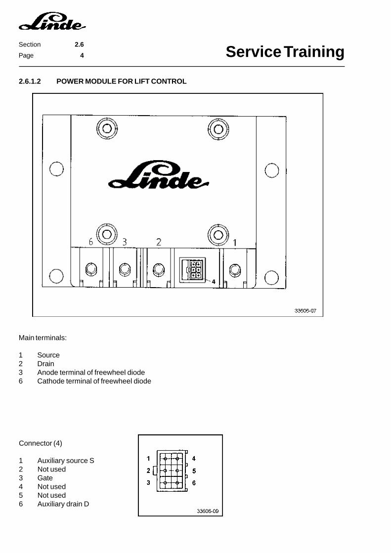
2.6.1.2 POWER MODULE FOR LIFT CONTROL
Main terminals:
1 Source2 Drain3 Anode terminal of freewheel diode6 Cathode terminal of freewheel diode
Connector (4)
1 Auxiliary source S2 Not used3 Gate4 Not used5 Not used6 Auxiliary drain D
Service TrainingSection 2.6
Page 5
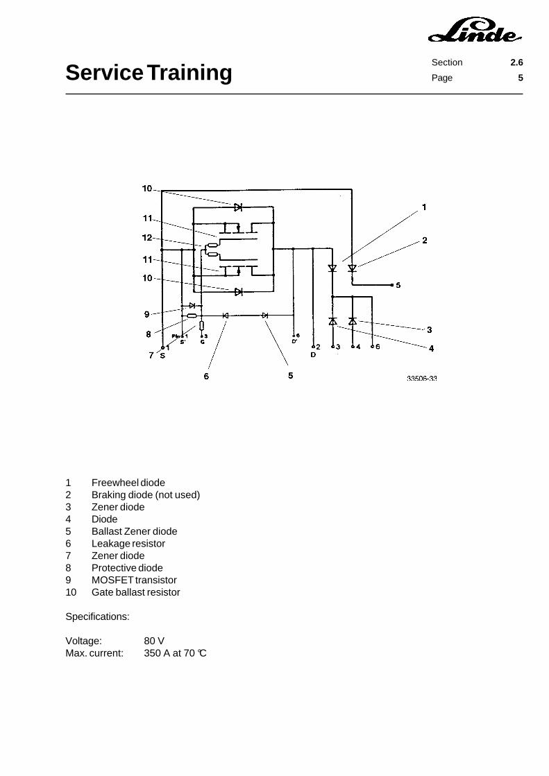
1 Freewheel diode2 Braking diode (not used)3 Zener diode4 Diode5 Ballast Zener diode6 Leakage resistor7 Zener diode8 Protective diode9 MOSFET transistor10 Gate ballast resistor
Specifications:
Voltage: 80 VMax. current: 350 A at 70 °C

Service TrainingSection 2.6
Page 6
2.6.1.3 POWER MODULE TESTS
The tests for the traction and lift control power module are the same.
TEST CONDITIONS:
- To test the power modules, you need a multimeter for measuring impedance and a 9 Volt block battery.- When performing the test with the modules on the truck, disconnect the battery plug and disconnect the
main circuit lines on the power module..
TESTING IF POWER MODULE IS OFF
- Connect the ohmmeter to source 1 and drain 2 (+ lead to the drain and - lead to the source). If there is novoltage measured at the gate, the module is off. The impedance between source and drain is highlyresistive.If the impedance between source and drain is low, the module is not working properly.
Service TrainingSection 2.6
Page 7
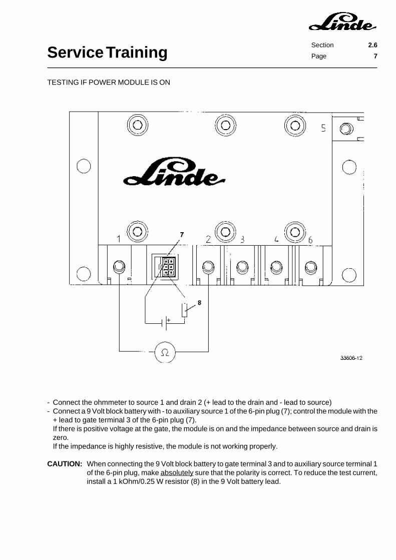
- Connect the ohmmeter to source 1 and drain 2 (+ lead to the drain and - lead to source)- Connect a 9 Volt block battery with - to auxiliary source 1 of the 6-pin plug (7); control the module with the
+ lead to gate terminal 3 of the 6-pin plug (7).If there is positive voltage at the gate, the module is on and the impedance between source and drain iszero.If the impedance is highly resistive, the module is not working properly.
CAUTION: When connecting the 9 Volt block battery to gate terminal 3 and to auxiliary source terminal 1of the 6-pin plug, make absolutely sure that the polarity is correct. To reduce the test current,install a 1 kOhm/0.25 W resistor (8) in the 9 Volt battery lead.
TESTING IF POWER MODULE IS ON
Service TrainingSection 2.6
Page 8
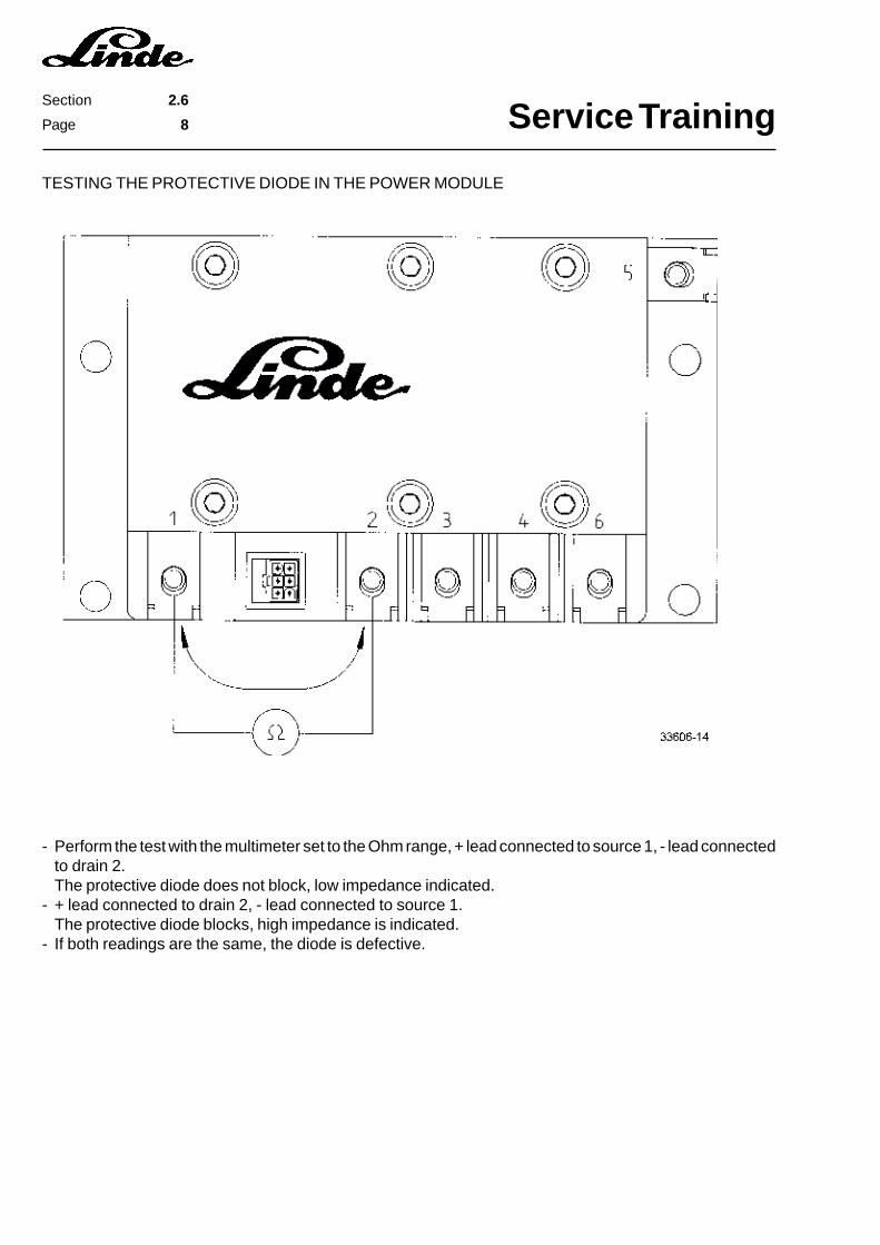
TESTING THE PROTECTIVE DIODE IN THE POWER MODULE
- Perform the test with the multimeter set to the Ohm range, + lead connected to source 1, - lead connectedto drain 2.The protective diode does not block, low impedance indicated.
- + lead connected to drain 2, - lead connected to source 1.The protective diode blocks, high impedance is indicated.
- If both readings are the same, the diode is defective.
Service TrainingSection 2.6
Page 9
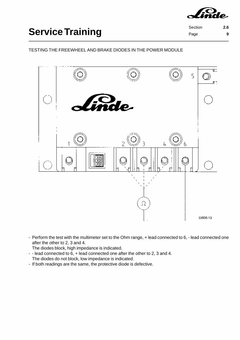
- Perform the test with the multimeter set to the Ohm range, + lead connected to 6, - lead connected oneafter the other to 2, 3 and 4.The diodes block, high impedance is indicated.
- - lead connected to 6, + lead connected one after the other to 2, 3 and 4.The diodes do not block, low impedance is indicated.
- If both readings are the same, the protective diode is defective.
TESTING THE FREEWHEEL AND BRAKE DIODES IN THE POWER MODULE
Service TrainingSection 2.6
Page 10
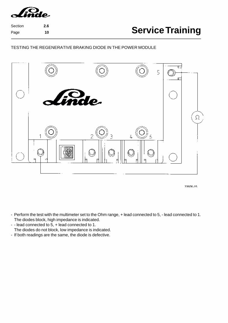
TESTING THE REGENERATIVE BRAKING DIODE IN THE POWER MODULE
- Perform the test with the multimeter set to the Ohm range, + lead connected to 5, - lead connected to 1.The diodes block, high impedance is indicated.
- - lead connected to 5, + lead connected to 1.The diodes do not block, low impedance is indicated.
- If both readings are the same, the diode is defective.
Service TrainingSection 2.6
Page 11
2.6.1.4 INSTALLATION OF THE POWER MODULES
The power modules used are of the MOSFET type. MOS transistors react sensitively to static discharges.Static charges can already arise when walking over a carpet. In the worst case, the body can be chargedup to 35,000 V.
CAUTION: Before working on the power modules, the human body must be discharged by touching earth(e.g. water pipe).Handle the power modules carefully to prevent damage to the cooling area and to the connector.
- Clean the underside of the power module in the area of the heat sink of any dust and foreign objects.- To reduce the heat transfer resistance between the power module and the counterweight,using a spatula,
apply a thin coating of thermal compound WPV10 to the mounting area of the power module- Position the power module correctly.- Tighten the M10x35 socket head screws alternately to a torque of 49 Nm.- Insert the plug.
CAUTION: The M10x35 socket head screws must be tightened to the proper torque to ensure the correctcontact of the power module.After 30 minutes, tighten alternate M10x35 socket head screws again.
Service TrainingSection 2.6
Page 12
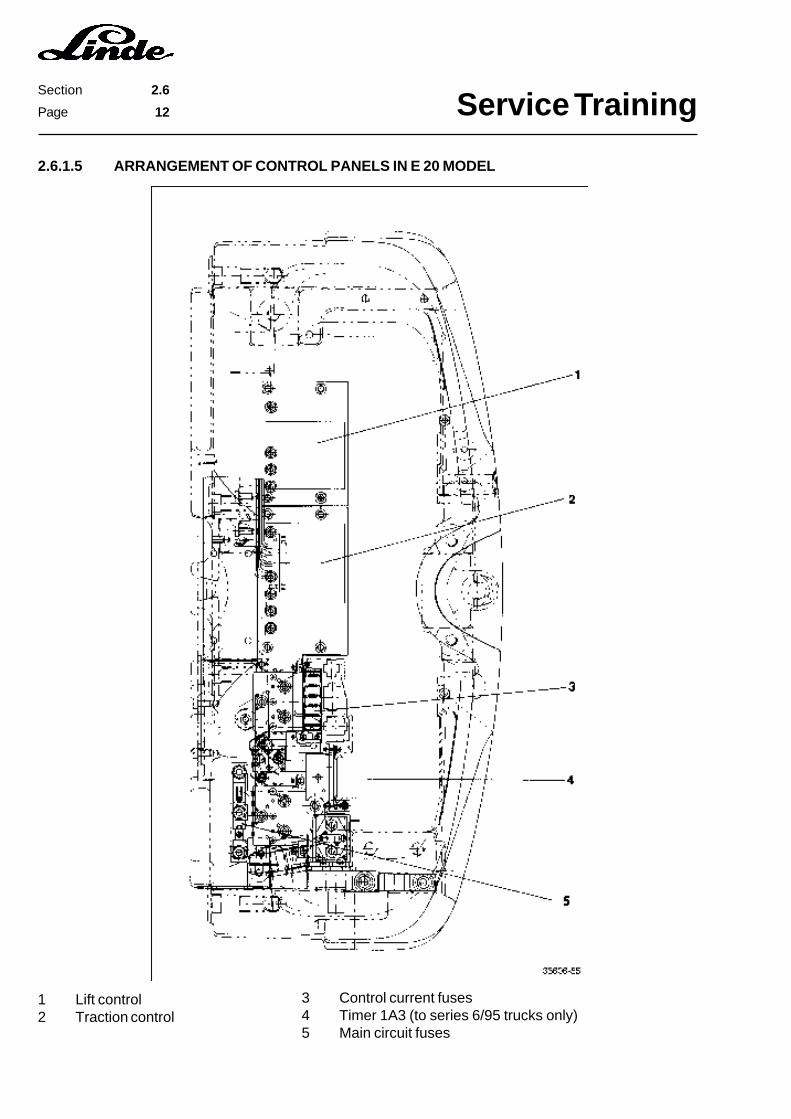
2.6.1.5 ARRANGEMENT OF CONTROL PANELS IN E 20 MODEL
1 Lift control2 Traction control
3 Control current fuses4 Timer 1A3 (to series 6/95 trucks only)5 Main circuit fuses
Service TrainingSection 2.6
Page 13
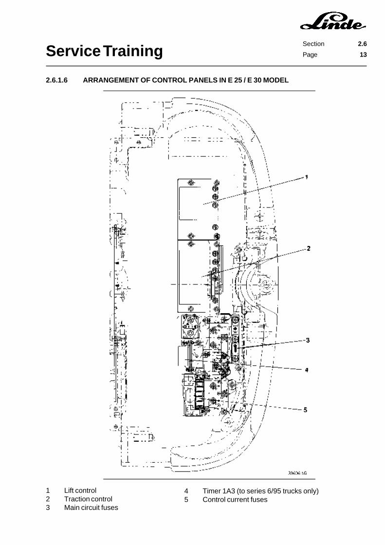
2.6.1.6 ARRANGEMENT OF CONTROL PANELS IN E 25 / E 30 MODEL
1 Lift control2 Traction control3 Main circuit fuses
4 Timer 1A3 (to series 6/95 trucks only)5 Control current fuses
Service TrainingSection 2.6
Page 14
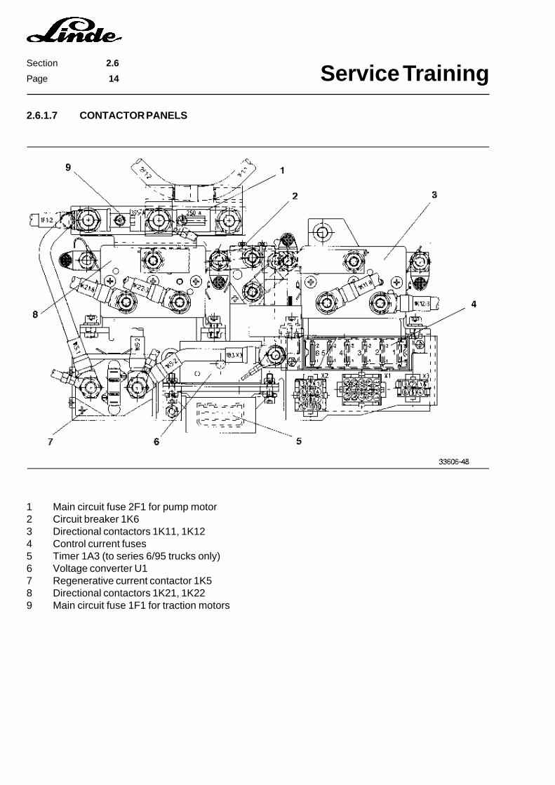
2.6.1.7 CONTACTOR PANELS
1 Main circuit fuse 2F1 for pump motor2 Circuit breaker 1K63 Directional contactors 1K11, 1K124 Control current fuses5 Timer 1A3 (to series 6/95 trucks only)6 Voltage converter U17 Regenerative current contactor 1K58 Directional contactors 1K21, 1K229 Main circuit fuse 1F1 for traction motors

Service TrainingSection 2.6
Page 15
Service TrainingSection 2.6
Page 16
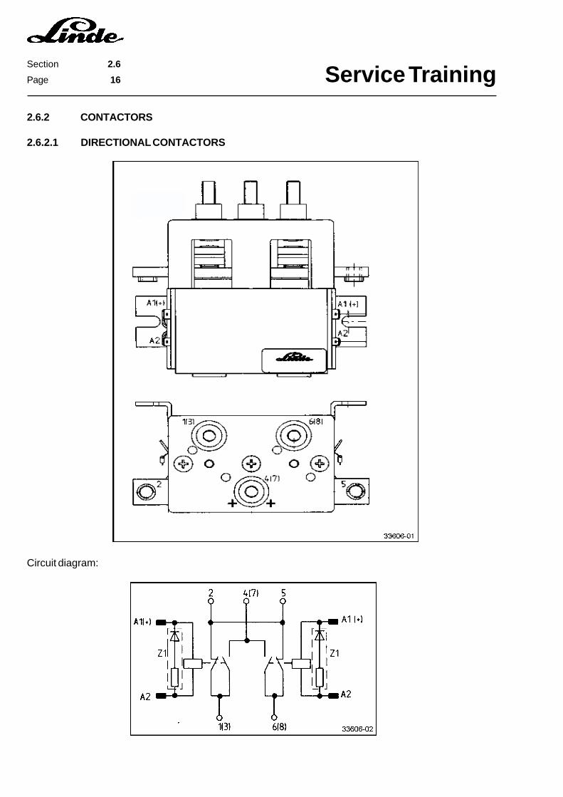
2.6.2 CONTACTORS
2.6.2.1 DIRECTIONAL CONTACTORS
Circuit diagram:

Service TrainingSection 2.6
Page 17
CONTACTOR TIP RENEWAL
- Remove the hexagonal nuts (8), disconnect the electric cables.- Remove the hexagonal nuts (4a) on the tip plate (5) and disconnect the electric cables.- Remove the Phillips screws (1) and take off the cover (2). (Note the position of the + mark.)- Remove the movable tip (4) along with the tip spring (3).- Remove the tip plate (5).- Renew the plastic part (6).- Install new tip plate (5).- Install a new tip (4) along with a new tip spring (3).- Renew the fixed contacts on the cover (2).- Install the cover (2), ensuring that the + mark is correctly positioned.
NOTE: The contactor tip kit consists of items 3, 4, 5 and 6 and the fixed tips in the cover.

Service TrainingSection 2.6
Page 18
2.6.2.2 REGENERATIVE BRAKING CONTACTOR 1K5
The regenerative braking contactor 1K5 has a microswitch 1S10 (1) built into the top for monitoring the correctswitching operation of the contactor.
Circuit diagram:
1
1
Service TrainingSection 2.6
Page 19
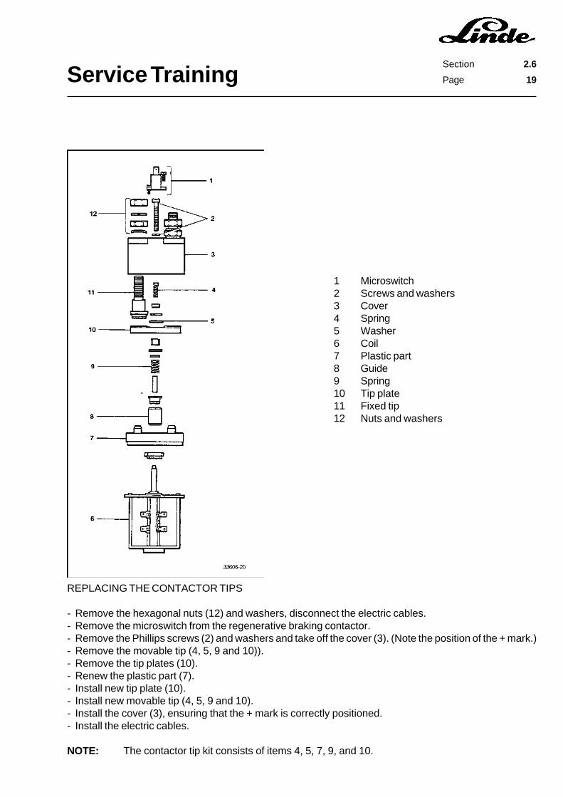
1 Microswitch2 Screws and washers3 Cover4 Spring5 Washer6 Coil7 Plastic part8 Guide9 Spring10 Tip plate11 Fixed tip12 Nuts and washers
REPLACING THE CONTACTOR TIPS
- Remove the hexagonal nuts (12) and washers, disconnect the electric cables.- Remove the microswitch from the regenerative braking contactor.- Remove the Phillips screws (2) and washers and take off the cover (3). (Note the position of the + mark.)- Remove the movable tip (4, 5, 9 and 10)).- Remove the tip plates (10).- Renew the plastic part (7).- Install new tip plate (10).- Install new movable tip (4, 5, 9 and 10).- Install the cover (3), ensuring that the + mark is correctly positioned.- Install the electric cables.
NOTE: The contactor tip kit consists of items 4, 5, 7, 9, and 10.
Service TrainingSection 2.6
Page 20
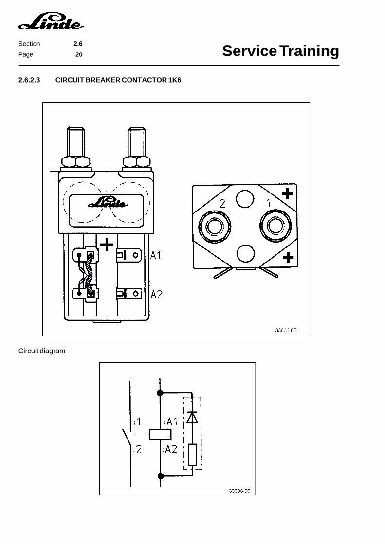
2.6.2.3 CIRCUIT BREAKER CONTACTOR 1K6
Circuit diagram
Service TrainingSection 2.6
Page 21
2.6.2.4 TESTING THE PROTECTIVE CIRCUITRY
The contactors are provided with a protective circuitry (diode and resistor) at the coils.
TEST PROCEDURE:
- Disconnect the battery plug.- Disconnect the connector at the contactor coils.- Apply a voltage of approx. 4 V to the coils (2 cells of the truck battery or a 4.5 V flat battery) and measure
the current.- Reverse the poles of the power source.- The protective circuit is okay if the two test readings are clearly different.- If both test readings are identical, renew the protective circuitry.

Service TrainingSection 2.6
Page 22
1 Main circuit fuse for traction motors 1F1, 355 A2 Main circuit fuse for pump motor 2F1, 250 A3 Main circuit fuse for regenerative braking 1F3, 100 A, located on mounting plate for RH diode 1V1
2.6.3.2 MAIN CIRCUIT FUSES IN MODEL E 25 / E 30
1 Main circuit fuse for pump motor 2F1, 250 A2 Main circuit fuse for traction motors 1F1, 355 A3 Main circuit fuse for regenerative braking 1F3, 100 A, located on mounting plate for RH diode 1V1
2.6.3 FUSES
2.6.3.1 MAIN CIRCUIT FUSES IN MODEL E 20
Remove the cover to gain access to the main circuit fuses.
Service TrainingSection 2.6
Page 23
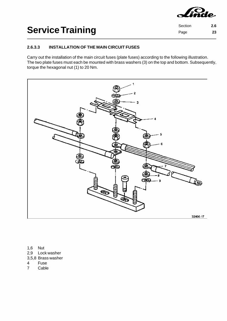
1,6 Nut2,9 Lock washer3,5,8 Brass washer4 Fuse7 Cable
2.6.3.3 INSTALLATION OF THE MAIN CIRCUIT FUSES
Carry out the installation of the main circuit fuses (plate fuses) according to the following illustration.The two plate fuses must each be mounted with brass washers (3) on the top and bottom. Subsequently,torque the hexagonal nut (1) to 20 Nm.
Service TrainingSection 2.6
Page 24
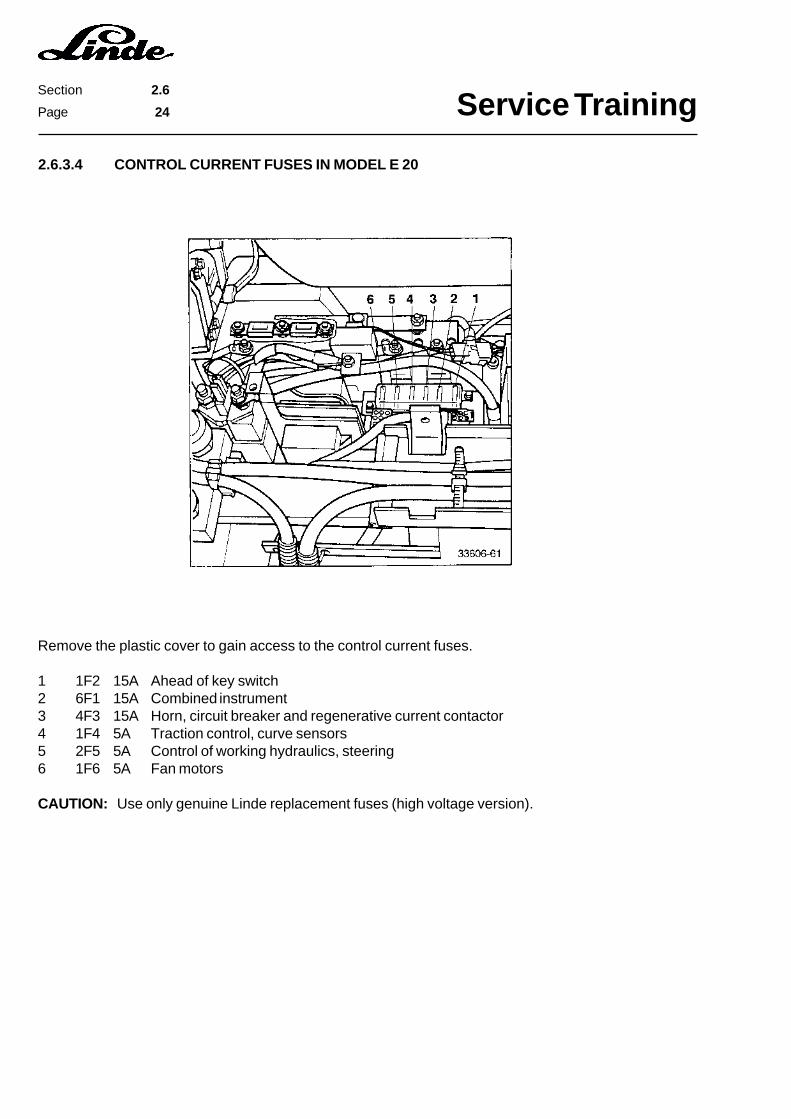
Remove the plastic cover to gain access to the control current fuses.
1 1F2 15A Ahead of key switch2 6F1 15A Combined instrument3 4F3 15A Horn, circuit breaker and regenerative current contactor4 1F4 5A Traction control, curve sensors5 2F5 5A Control of working hydraulics, steering6 1F6 5A Fan motors
CAUTION: Use only genuine Linde replacement fuses (high voltage version).
2.6.3.4 CONTROL CURRENT FUSES IN MODEL E 20
Service TrainingSection 2.6
Page 25
2.6.3.5 CONTROL CURRENT FUSES IN MODEL E 25 / E 30
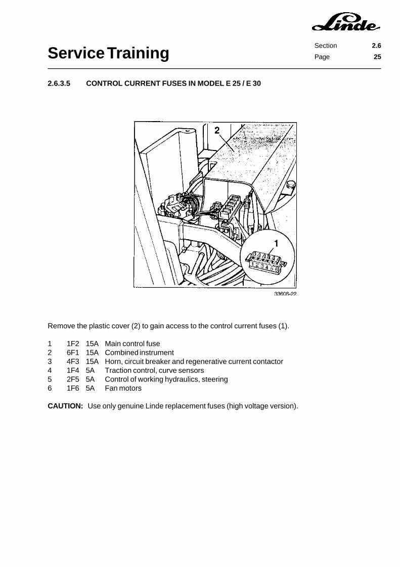
Remove the plastic cover (2) to gain access to the control current fuses (1).
1 1F2 15A Main control fuse2 6F1 15A Combined instrument3 4F3 15A Horn, circuit breaker and regenerative current contactor4 1F4 5A Traction control, curve sensors5 2F5 5A Control of working hydraulics, steering6 1F6 5A Fan motors
CAUTION: Use only genuine Linde replacement fuses (high voltage version).
Service TrainingSection 2.6
Page 26
2.6.4 VOLTAGE CONVERTER
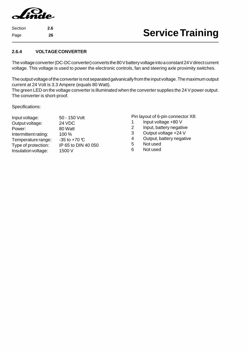
The voltage converter (DC-DC converter) converts the 80 V battery voltage into a constant 24 V direct currentvoltage. This voltage is used to power the electronic controls, fan and steering axle proximity switches.
The output voltage of the converter is not separated galvanically from the input voltage. The maximum outputcurrent at 24 Volt is 3.3 Ampere (equals 80 Watt).The green LED on the voltage converter is illuminated when the converter supplies the 24 V power output.The converter is short-proof.
Specifications:
Input voltage: 50 - 150 VoltOutput voltage: 24 VDCPower: 80 WattIntermittent rating: 100 %Temperature range: -35 to +70 °CType of protection: IP 65 to DIN 40 050Insulation voltage: 1500 V
Pin layout of 6-pin connector X8:1 Input voltage +80 V2 Input, battery negative3 Output voltage +24 V4 Output, battery negative5 Not used6 Not used

Service TrainingSection 2.6
Page 27
2.6.5 MAIN CIRCUIT SECTION TRACTION CONTROL
1K21 Reverse contactor, left-hand1K22 Forward contactor, left-hand1M1 Traction motor, right-hand1M2 Traction motor, left-hand1R2 Resistor1V1 Diode1V6 Freewheel diode1V51 Brake diode1V52 Brake diode1V53 Regenerative current diode
G1 BatteryS2 Emergency off switch1A1 Power unit1B3 Current sensor1F1 Main circuit fuse1F3 Fuse1K5 Regenerative current contactor1K11 Reverse contactor, right-hand1K12 Forward contactor, right-hand
Service TrainingSection 2.6
Page 28
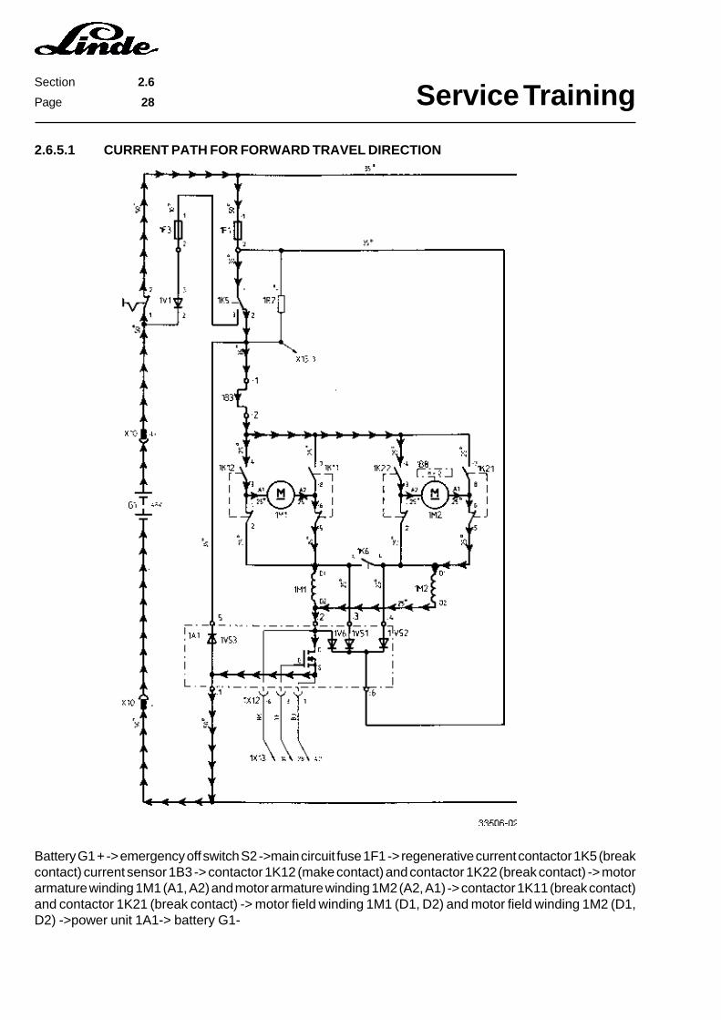
2.6.5.1 CURRENT PATH FOR FORWARD TRAVEL DIRECTION
Battery G1 + -> emergency off switch S2 ->main circuit fuse 1F1 -> regenerative current contactor 1K5 (breakcontact) current sensor 1B3 -> contactor 1K12 (make contact) and contactor 1K22 (break contact) -> motorarmature winding 1M1 (A1, A2) and motor armature winding 1M2 (A2, A1) -> contactor 1K11 (break contact)and contactor 1K21 (break contact) -> motor field winding 1M1 (D1, D2) and motor field winding 1M2 (D1,D2) ->power unit 1A1-> battery G1-
Service TrainingSection 2.6
Page 29
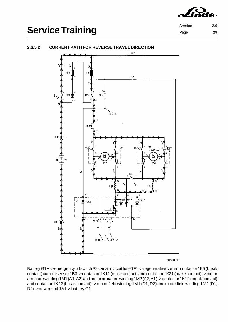
2.6.5.2 CURRENT PATH FOR REVERSE TRAVEL DIRECTION
Battery G1 + -> emergency off switch S2 ->main circuit fuse 1F1 -> regenerative current contactor 1K5 (breakcontact) current sensor 1B3 -> contactor 1K11 (make contact) and contactor 1K21 (make contact) -> motorarmature winding 1M1 (A1, A2) and motor armature winding 1M2 (A2, A1) -> contactor 1K12 (break contact)and contactor 1K22 (break contact) -> motor field winding 1M1 (D1, D2) and motor field winding 1M2 (D1,D2) ->power unit 1A1-> battery G1-

Service TrainingSection 2.6
Page 30
2.6.5.3 FREEWHEEL CIRCUIT
When the FETs in the power module are turned off, the traction motors induce a voltage. The induced voltageis negative at terminals A1 and A2 and positive at D2. Therefore a freewheel current can flow throughfreewheel diode 1V6 bypassing the motors.
Service TrainingSection 2.6
Page 31
2.6.5.4 REGENERATIVE CURRENT BRAKING
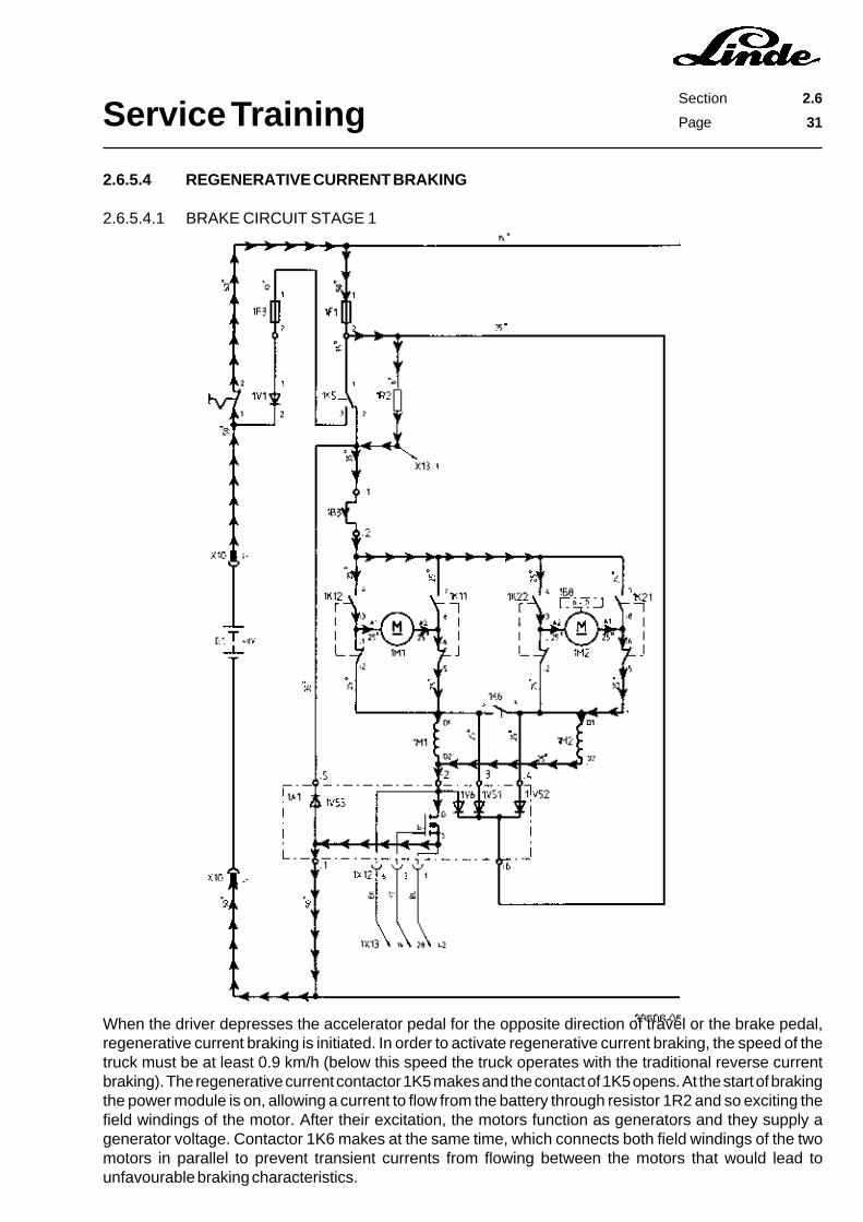
2.6.5.4.1 BRAKE CIRCUIT STAGE 1
When the driver depresses the accelerator pedal for the opposite direction of travel or the brake pedal,regenerative current braking is initiated. In order to activate regenerative current braking, the speed of thetruck must be at least 0.9 km/h (below this speed the truck operates with the traditional reverse currentbraking). The regenerative current contactor 1K5 makes and the contact of 1K5 opens. At the start of brakingthe power module is on, allowing a current to flow from the battery through resistor 1R2 and so exciting thefield windings of the motor. After their excitation, the motors function as generators and they supply agenerator voltage. Contactor 1K6 makes at the same time, which connects both field windings of the twomotors in parallel to prevent transient currents from flowing between the motors that would lead tounfavourable braking characteristics.

Service TrainingSection 2.6
Page 32
2.6.5.4.2 BRAKING CIRCUIT STAGE 2
As soon as the motors act as generators, a regenerative current flows through the brake diodes 1V51 and1V52 back to the battery. The battery negative pole is connected to the armature winding of the motors viaregenerative brake diode 1V53.
Service TrainingSection 2.6
Page 33
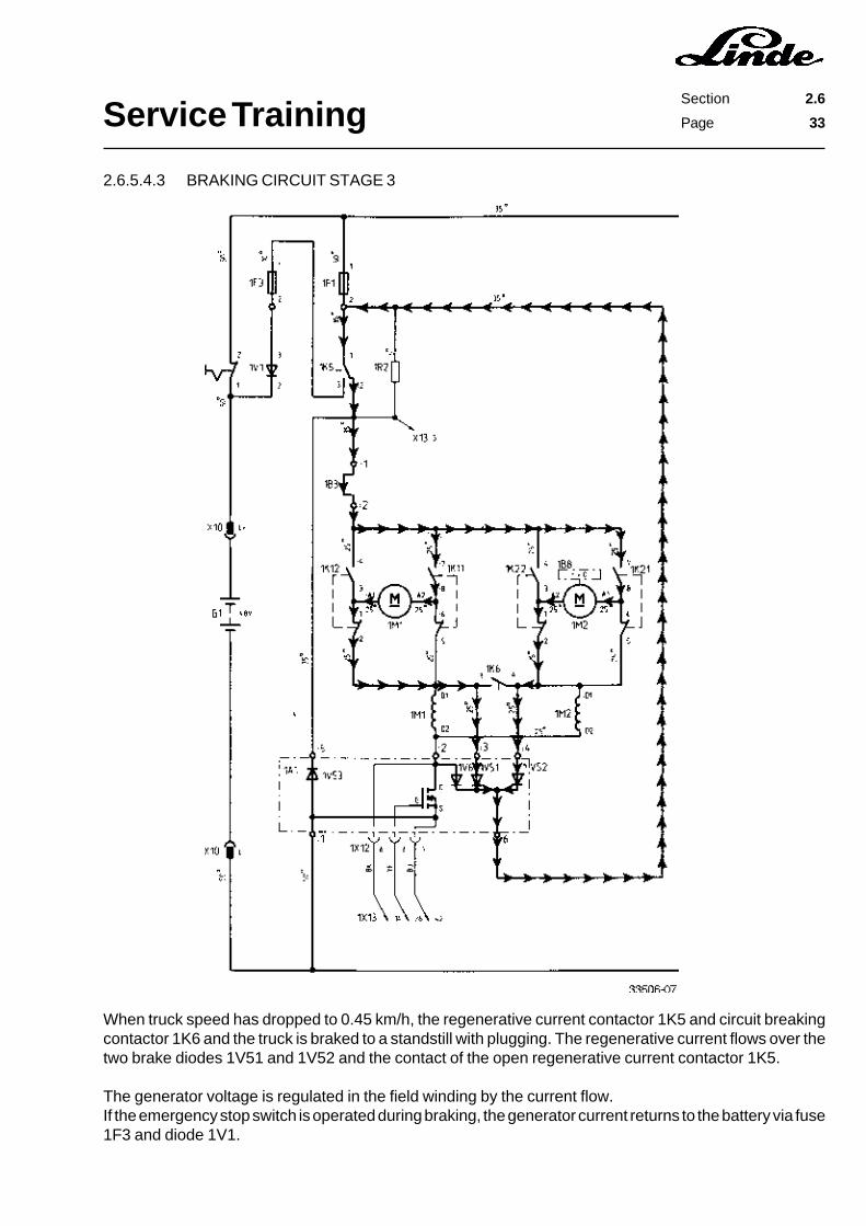
2.6.5.4.3 BRAKING CIRCUIT STAGE 3
When truck speed has dropped to 0.45 km/h, the regenerative current contactor 1K5 and circuit breakingcontactor 1K6 and the truck is braked to a standstill with plugging. The regenerative current flows over thetwo brake diodes 1V51 and 1V52 and the contact of the open regenerative current contactor 1K5.
The generator voltage is regulated in the field winding by the current flow.If the emergency stop switch is operated during braking, the generator current returns to the battery via fuse1F3 and diode 1V1.
Service TrainingSection 2.6
Page 34
2.6.6 ELECTRONIC TRACTION CONTROL UNIT
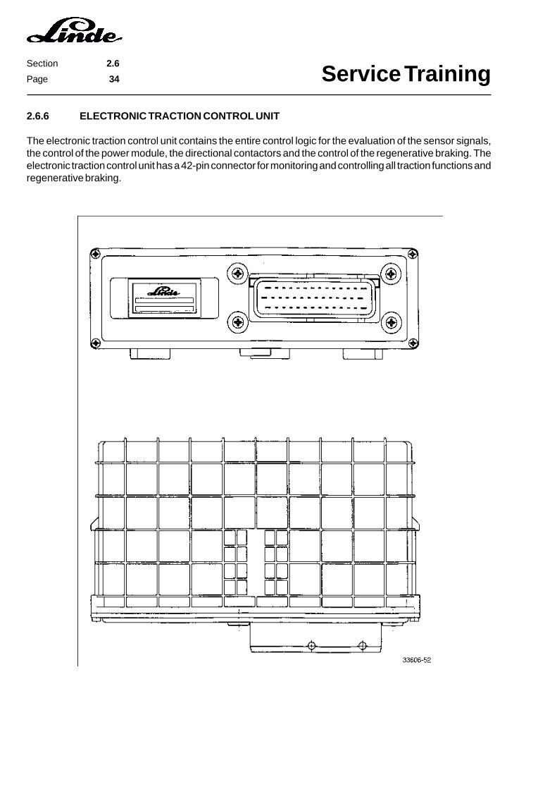
The electronic traction control unit contains the entire control logic for the evaluation of the sensor signals,the control of the power module, the directional contactors and the control of the regenerative braking. Theelectronic traction control unit has a 42-pin connector for monitoring and controlling all traction functions andregenerative braking.
Service TrainingSection 2.6
Page 35
PIN LAYOUT
Pins for connector 1X13
Terminal Colours Functions
1 white/yellow signal of brake current switch 1S52 not used3 red/blue negative directional contactor 1K224 black/yellow negative circuit breaking contactor 1K65 white/blue signal microswitch 1S10 (regenerative current contactor 1K5)6 grey/white signal of left curve sensor 1B97 black/blue encoding for single-pedal models8 black forward direction signal, single-pedal models9 grey/yellow signal of handbrake switch 1S410 yellow/green signal of current sensor 1B311 green signal of speed sensor 1B8, channel A12 yellow power supply 15 V for 1A4 and 1B313 grey power supply 24 V14 black auxiliary drain of compact module15 black/grey power supply for directional contactors (when braking)16 not used17 red/green negative directional contactor 1K1118 violet negative regenerative current contactor 1K519 not used20 black/yellow signal of right curve sensor 1B1021 brown seat switch enable signal22 white reverse direction signal, single-pedal models23 black/green signal of temperature switch 1B6 and 1B7 (traction motors)24 red signal of accelerator sensor 1A4 (desired value)25 white signal of speed sensor 1B8, channel B26 centre feed 7.5 V27 green negative voltage for 1A4 and 1B328 yellow gate control in compact module29 blue negative voltage for directional contactor transistors30 white/green main circuit, regenerative current contactor 1K531 red/yellow negative of directional contactor 1K2132 red/white negative of directional contactor 1K1233 not used34 not used35 not used36 not used37 not used38 green speed reduction39 yellow 15 V power supply for speed sensor 1B840 not used41 green negative of power supply for speed sensor 1B842 blue auxiliary source in compact module
Service TrainingSection 2.6
Page 36
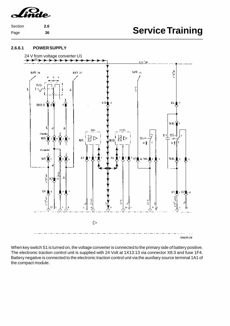
When key switch S1 is turned on, the voltage converter is connected to the primary side of battery positive.The electronic traction control unit is supplied with 24 Volt at 1X13:13 via connector X8:3 and fuse 1F4.Battery negative is connected to the electronic traction control unit via the auxiliary source terminal 1A1 ofthe compact module.
24 V from voltage converter U1
2.6.6.1 POWER SUPPLY
Service TrainingSection 2.6
Page 37
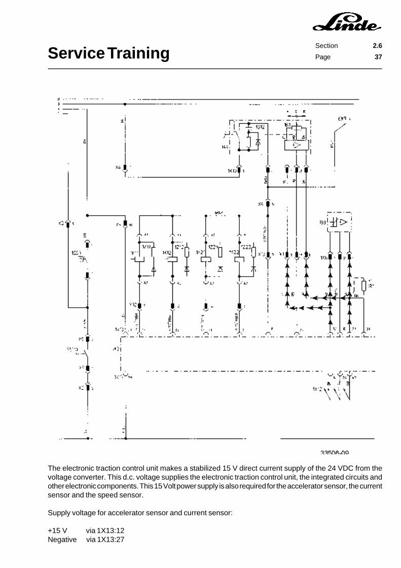
The electronic traction control unit makes a stabilized 15 V direct current supply of the 24 VDC from thevoltage converter. This d.c. voltage supplies the electronic traction control unit, the integrated circuits andother electronic components. This 15 Volt power supply is also required for the accelerator sensor, the currentsensor and the speed sensor.
Supply voltage for accelerator sensor and current sensor:
+15 V via 1X13:12Negative via 1X13:27
Service TrainingSection 2.6
Page 38
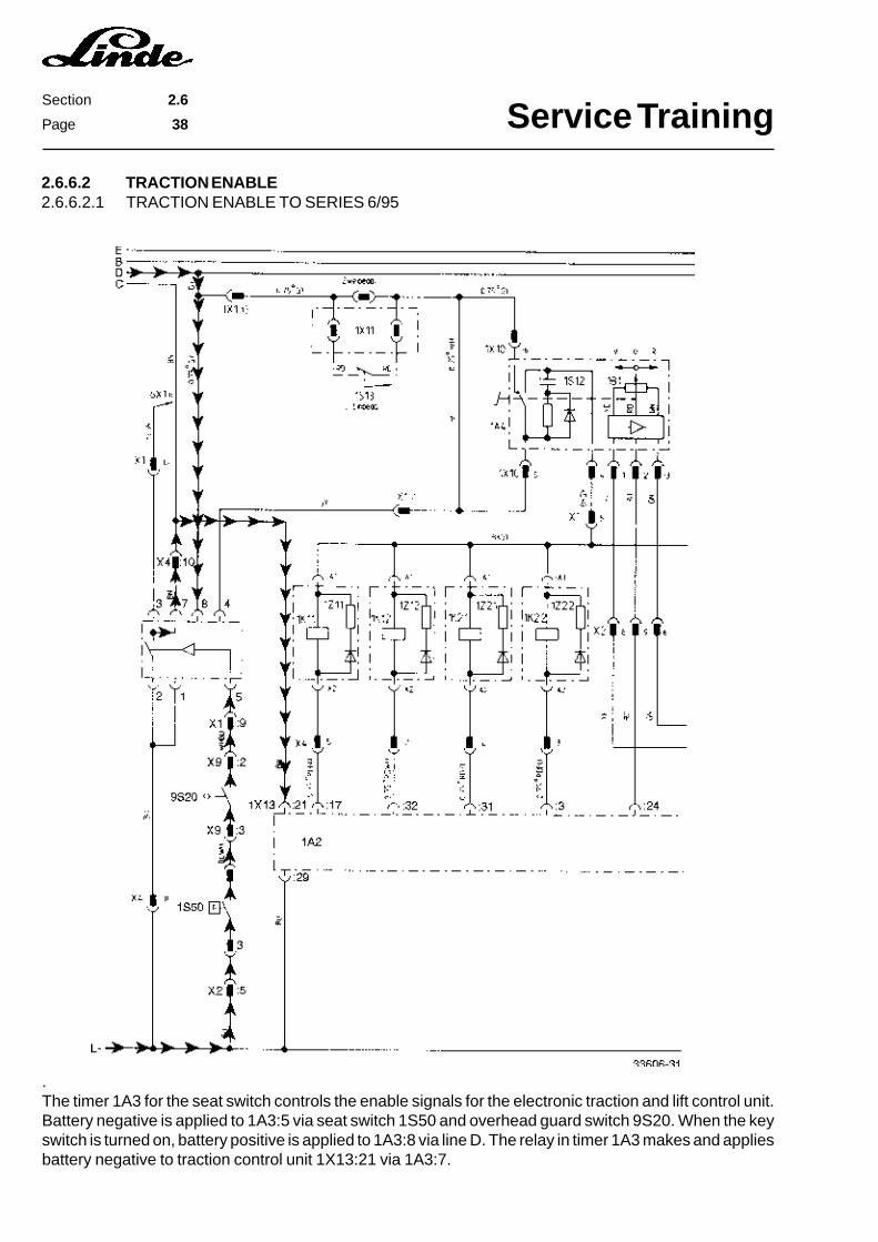
2.6.6.2 TRACTION ENABLE2.6.6.2.1 TRACTION ENABLE TO SERIES 6/95
.The timer 1A3 for the seat switch controls the enable signals for the electronic traction and lift control unit.Battery negative is applied to 1A3:5 via seat switch 1S50 and overhead guard switch 9S20. When the keyswitch is turned on, battery positive is applied to 1A3:8 via line D. The relay in timer 1A3 makes and appliesbattery negative to traction control unit 1X13:21 via 1A3:7.

Service TrainingSection 2.6
Page 39
2.6.6.2.2 TRACTION ENABLE FROM SERIES 7/95
Battery negative is applied to the traction module 1X13:21 via seat switch 1S50 and overhead guard switch9S20.
When seat switch 1S50 or overhead guard switch 9S20 is opened, the timer relay opens after a delay ofapprox. 2 seconds in order to prevent inappropriate switching when travelling on an uneven roadway.

Service TrainingSection 2.6
Page 40
Service TrainingSection 2.6
Page 41
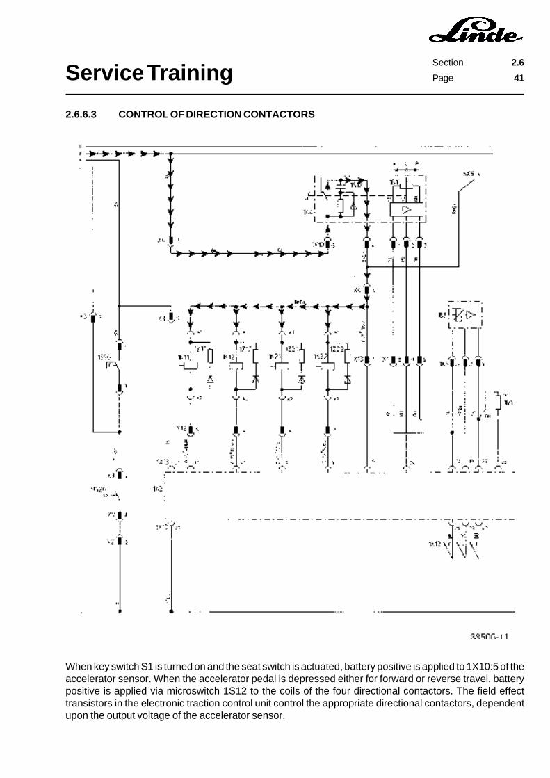
2.6.6.3 CONTROL OF DIRECTION CONTACTORS
When key switch S1 is turned on and the seat switch is actuated, battery positive is applied to 1X10:5 of theaccelerator sensor. When the accelerator pedal is depressed either for forward or reverse travel, batterypositive is applied via microswitch 1S12 to the coils of the four directional contactors. The field effecttransistors in the electronic traction control unit control the appropriate directional contactors, dependentupon the output voltage of the accelerator sensor.
Service TrainingSection 2.6
Page 42
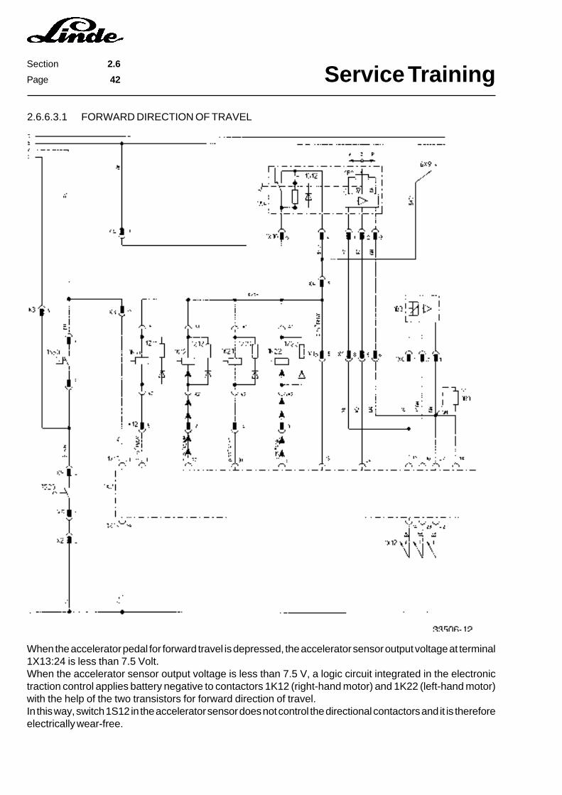
2.6.6.3.1 FORWARD DIRECTION OF TRAVEL
When the accelerator pedal for forward travel is depressed, the accelerator sensor output voltage at terminal1X13:24 is less than 7.5 Volt.When the accelerator sensor output voltage is less than 7.5 V, a logic circuit integrated in the electronictraction control applies battery negative to contactors 1K12 (right-hand motor) and 1K22 (left-hand motor)with the help of the two transistors for forward direction of travel.In this way, switch 1S12 in the accelerator sensor does not control the directional contactors and it is thereforeelectrically wear-free.

Service TrainingSection 2.6
Page 43
2.6.6.3.2 REVERSE DIRECTION OF TRAVEL
When the accelerator pedal for reverse travel is depressed, the accelerator sensor output voltage at terminal1X13:24 is over 7.5 Volt. The two transistors for reverse travel now apply battery negative to contactors 1K11(right-hand motor) and 1K21 (left-hand motor).
Service TrainingSection 2.6
Page 44
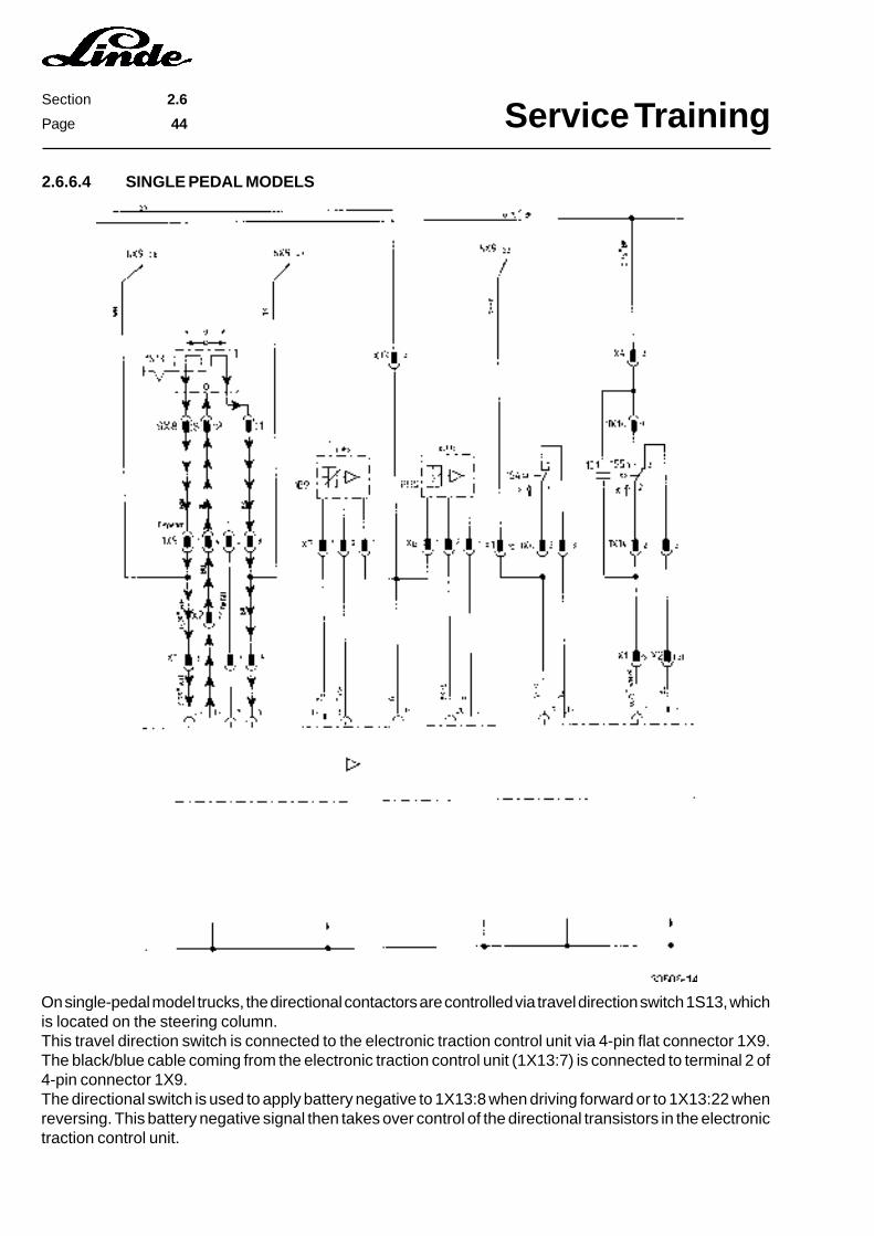
On single-pedal model trucks, the directional contactors are controlled via travel direction switch 1S13, whichis located on the steering column.This travel direction switch is connected to the electronic traction control unit via 4-pin flat connector 1X9.The black/blue cable coming from the electronic traction control unit (1X13:7) is connected to terminal 2 of4-pin connector 1X9.The directional switch is used to apply battery negative to 1X13:8 when driving forward or to 1X13:22 whenreversing. This battery negative signal then takes over control of the directional transistors in the electronictraction control unit.
2.6.6.4 SINGLE PEDAL MODELS
Service TrainingSection 2.6
Page 45
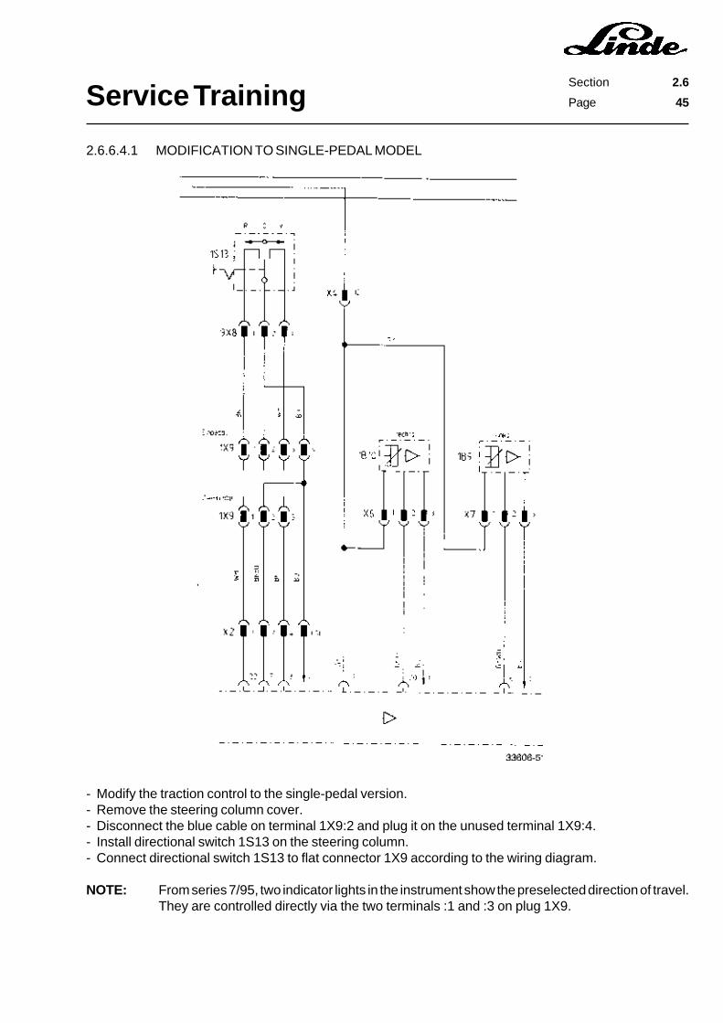
2.6.6.4.1 MODIFICATION TO SINGLE-PEDAL MODEL
- Modify the traction control to the single-pedal version.- Remove the steering column cover.- Disconnect the blue cable on terminal 1X9:2 and plug it on the unused terminal 1X9:4.- Install directional switch 1S13 on the steering column.- Connect directional switch 1S13 to flat connector 1X9 according to the wiring diagram.
NOTE: From series 7/95, two indicator lights in the instrument show the preselected direction of travel.They are controlled directly via the two terminals :1 and :3 on plug 1X9.

Service TrainingSection 2.6
Page 46
2.6.6.5 DRIVING AROUND CORNERS
The two proximity switches 1B9 and 1B10 are mounted on the steering axle for sensing the steering lock.They are actuated when the steering lock is accordingly.The two proximity switches are supplied with 24 VDC from the voltage converter via X6:1 or X7:1. The sensorsare connected to battery negative via terminals X6:3 or X7:3. They are activated by the steering cylinder.When travelling straight ahead, both sensors are activated and battery negative is applied to terminals :6and :20 in connector 1X13 of the electronic traction control unit. When the steering lock is over 40°, the sensorin question (1B9 = left-hand sensor, 1B10 = right-hand sensor) is no longer actuated and the battery negativesignal at 1X13:20 (left) or 1X13:6 (right) is cut off. As a result, the motor on the inside curve is turned off bymeans of the directional contactors.
Service TrainingSection 2.6
Page 47
2.6.6.5.1 SENSORS FOR STEERING POSITION
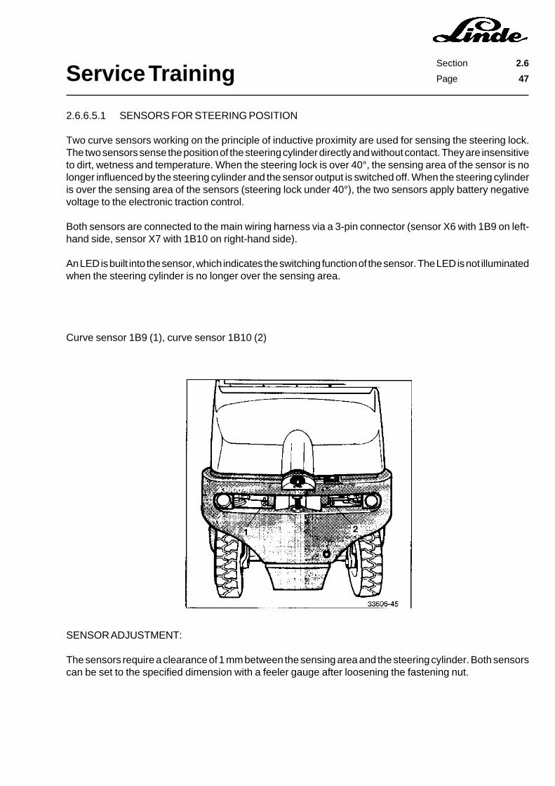
Two curve sensors working on the principle of inductive proximity are used for sensing the steering lock.The two sensors sense the position of the steering cylinder directly and without contact. They are insensitiveto dirt, wetness and temperature. When the steering lock is over 40°, the sensing area of the sensor is nolonger influenced by the steering cylinder and the sensor output is switched off. When the steering cylinderis over the sensing area of the sensors (steering lock under 40°), the two sensors apply battery negativevoltage to the electronic traction control.
Both sensors are connected to the main wiring harness via a 3-pin connector (sensor X6 with 1B9 on left-hand side, sensor X7 with 1B10 on right-hand side).
An LED is built into the sensor, which indicates the switching function of the sensor. The LED is not illuminatedwhen the steering cylinder is no longer over the sensing area.
Curve sensor 1B9 (1), curve sensor 1B10 (2)
SENSOR ADJUSTMENT:
The sensors require a clearance of 1 mm between the sensing area and the steering cylinder. Both sensorscan be set to the specified dimension with a feeler gauge after loosening the fastening nut.
Service TrainingSection 2.6
Page 48
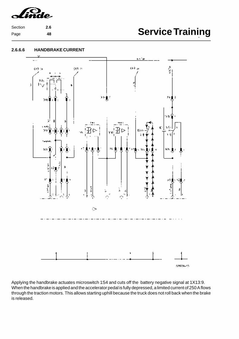
2.6.6.6 HANDBRAKE CURRENT
Applying the handbrake actuates microswitch 1S4 and cuts off the battery negative signal at 1X13:9.When the handbrake is applied and the accelerator pedal is fully depressed, a limited current of 250 A flowsthrough the traction motors. This allows starting uphill because the truck does not roll back when the brakeis released.
Service TrainingSection 2.6
Page 49
2.6.6.6.1 CHECKING THE MAXIMUM CURRENT AND HANDBRAKE CURRENT
Maximum current
- Jack up the truck and block it up safely.- Connect current measuring pliers WM 120 to the cable from current sensor 1B3 to the directional
contactors.- Fully depress the brake pedal and accelerator pedal.
NOTE: The wheels must not turn.
- Read the current.- The maximum current must be approx. 430 Ampere.
CAUTION: Perform the measurement quickly in order to prevent damage to the traction motors. Themaximum measuring time should not exceed 30 seconds.
Handbrake current
- Install the current measuring pliers as described above.- Engage the handbrake and fully depress the accelerator pedal.- Read the current.- The handbrake current must be approx. 150 Ampere.
NOTE: If the two current readings are not correct, the electronic traction control unit or the current sensormust be replaced.
Service TrainingSection 2.6
Page 50
2.6.6.7 TEMPERATURE MONITORING TRACTION MOTORS
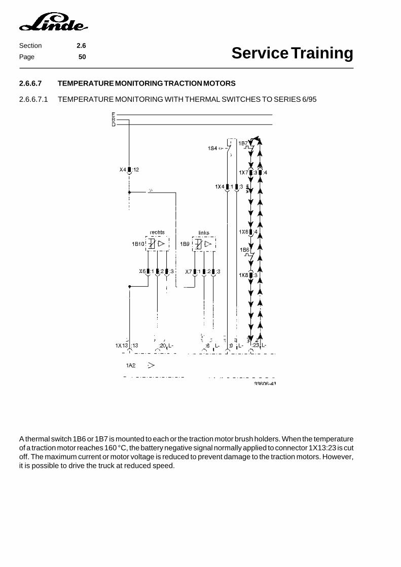
A thermal switch 1B6 or 1B7 is mounted to each or the traction motor brush holders. When the temperatureof a traction motor reaches 160 °C, the battery negative signal normally applied to connector 1X13:23 is cutoff. The maximum current or motor voltage is reduced to prevent damage to the traction motors. However,it is possible to drive the truck at reduced speed.
2.6.6.7.1 TEMPERATURE MONITORING WITH THERMAL SWITCHES TO SERIES 6/95
Service TrainingSection 2.6
Page 51
2.6.6.7.2 TEMPERATURE MONITORING WITH THERMAL SENSORS FROM SERIES 7/95
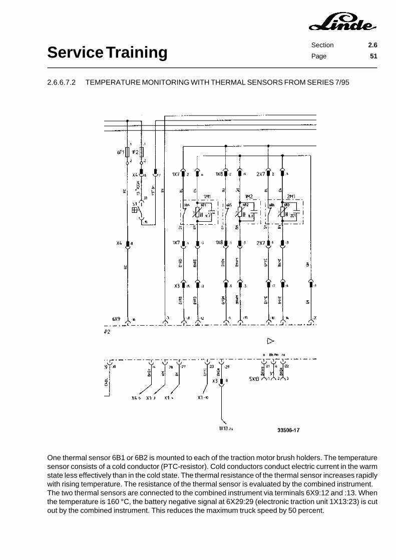
One thermal sensor 6B1 or 6B2 is mounted to each of the traction motor brush holders. The temperaturesensor consists of a cold conductor (PTC-resistor). Cold conductors conduct electric current in the warmstate less effectively than in the cold state. The thermal resistance of the thermal sensor increases rapidlywith rising temperature. The resistance of the thermal sensor is evaluated by the combined instrument.The two thermal sensors are connected to the combined instrument via terminals 6X9:12 and :13. Whenthe temperature is 160 °C, the battery negative signal at 6X29:29 (electronic traction unit 1X13:23) is cutout by the combined instrument. This reduces the maximum truck speed by 50 percent.

Service TrainingSection 2.6
Page 52
The thermal sensors are mounted on the motor brush holders and connected to the main wire harness withconnectors 1X7, 1X8 and 2X7. Depending on the temperature, the resistance of the thermal sensors changesaccording to the following characteristic line:
Resistance
TemperatureTest:
- Jack up the truck and support it safely.- Actuate the emergency stop switch.- Disconnect the connector to the motor in question.- Measure the resistance between connector 1X7 or 1X8 at terminals :3 and :4. When the motor is cold (25
°C), the resistance should be approx. 500 Ohm.- Drive the truck until the motor reaches operating temperature.- Measure the resistance again. When the motor is warm (80 °C), the resistance should be approx. 800
Ohm.
2.6.6.8 SPEED REDUCTION
To limit the speed of the electric fork trucks it is necessary to separate the bridge between 1X13:27 and1X13:38 and to solder fixed resistor 1R1. This fixed resistor is switched via an auxiliary 24 V relay 1K7. Assoon as regenerative braking is activated, the speed reduction is cut out by the regenerative current contactorwith microswitch 1S10.
NOTE: Only the travel speed of the truck will be reduced. The maximum climbing ability of the truckdoes not change. The resistance of 1R1 can be determined according to the following table.Replacement parts for the speed reduction are available as custom equipment (UPA).

Service TrainingSection 2.6
Page 53
1R1 Resistor1K7 Relay 24 V
NOTE: The components marked with a broken line are already installed in the truck.
Speed Resistance
6 km/h 26,1 k�7 km/h 24,9 k�8 km/h 24,3 k�9 km/h 23,7 k�10 km/h 23,2 k�11 km/h 22,1 k�12 km/h 21,5 k�13 km/h 21,0 k�14 km/h 20,0 k�15 km/h 18,2 k�

Service TrainingSection 2.6
Page 54
2.6.6.9 REGENERATIVE BRAKING
As described in the main circuit section, regenerative braking can be initiated in one of two ways.
1. By selecting the opposite direction with the accelerator pedal or the directional switch.
When the truck reverses, the accelerator sensor signal at 1X13:24 changes to the opposite direction, causingregenerative braking to be initiated. On trucks with a directional switch, regenerative braking is controlledvia the terminals 1X13:22 and 1X13:18.

Service TrainingSection 2.6
Page 55
2. By depressing the brake pedal.
Depressing the brake pedal applies the battery positive signal from the key switch via braking current switch1S5 to 1X13:1 at the electronic traction control unit. The battery positive signal flows on via 1X13:15 to thepositive directional contactor terminals.
When regenerative braking is activated, the battery negative signal is applied via 1X13:18 to regenerativebraking contactor 1K5 and via 1X13:4 to circuit breaking contactor 1K6. Both contactors remain activateduntil the truck speed has reduced to approx. 0.45 km/h.
Truck speed and the direction of travel are sensed by a speed and direction of rotation sensor mounted onthe left-hand traction motor 1M2.
NOTE: Regenerative braking can only be started when truck speed is over 0.9 km/h.
2.6.6.9.1 SPEED SENSOR IN THE TRACTION MOTOR
The speed sensor is powered with a d.c. voltage of 5 Volt via an amplifier circuit. The sensor supplies twooutput signals, which have a different frequency or phase relationship, depending upon the motor speed anddirection of rotation.
FUNCTIONAL CHECK:
Power supply:
- Jack up the truck and support it safely.- Check the power supply for amplifier 1A5.- Connect a voltmeter to 1X1.2:1 and 1X1.2:3.
The supply voltage must be 15 Volt.- Check the power supply for the speed sensor.- Connect a voltmeter to 1X1.1:1 and 1X1.1:3.
The supply voltage must be 5 Volt.
Output signal:
- Check the speed sensor output signal.- Connect a voltmeter to 1X1.2:2 and 1X1.2:3.- Let the traction motors run.
The output voltage must be approx. 7.5 Volt.- Connect a voltmeter to 1X1.2:4 and 1X1.2:3.- Let the traction motors run.
The output voltage must be approx. 7.5 Volt.
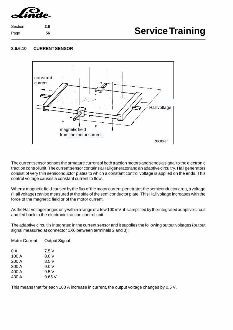
Service TrainingSection 2.6
Page 56
2.6.6.10 CURRENT SENSOR
The current sensor senses the armature current of both traction motors and sends a signal to the electronictraction control unit. The current sensor contains a Hall generator and an adaptive circuitry. Hall generatorsconsist of very thin semiconductor plates to which a constant control voltage is applied on the ends. Thiscontrol voltage causes a constant current to flow.
When a magnetic field caused by the flux of the motor current penetrates the semiconductor area, a voltage(Hall voltage) can be measured at the side of the semiconductor plate. This Hall voltage increases with theforce of the magnetic field or of the motor current.
As the Hall voltage ranges only within a range of a few 100 mV, it is amplified by the integrated adaptive circuitand fed back to the electronic traction control unit.
The adaptive circuit is integrated in the current sensor and it supplies the following output voltages (outputsignal measured at connector 1X6 between terminals 2 and 3):
Motor Current Output Signal
0 A 7.5 V100 A 8.0 V200 A 8.5 V300 A 9.0 V400 A 9.5 V430 A 9.65 V
This means that for each 100 A increase in current, the output voltage changes by 0.5 V.
Hall voltage
magnetic fieldfrom the motor current
constantcurrent
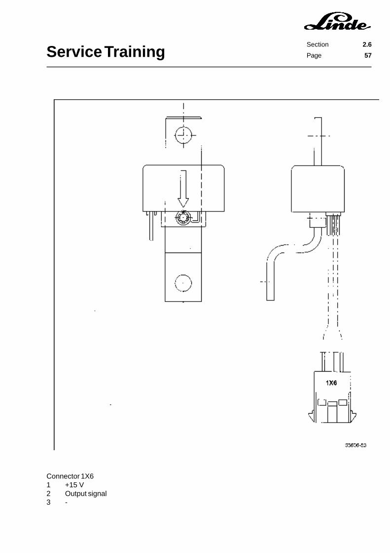
Service TrainingSection 2.6
Page 57
Connector 1X61 +15 V2 Output signal3 -
Service TrainingSection 2.6
Page 58
2.6.7 LTM CONTROL FOR WORKING HYDRAULIC SYSTEM AND STEERING
Electric fork trucks need hydraulic pumps driven by electric motors for the operation of hydraulic cylindersfor lifting, tilting, auxiliary hydraulics and steering. On series 336 trucks only one hydraulic pump is used forthe operation of the working hydraulic system and the power steering. The power requirement of the varioushydraulic cylinders and the attachments differs greatly. For example, a larger volume of oil is required forthe lifting than for tilting or operating the sideshift. If the working hydraulics pump is used for steeringpurposes, only a low pump motor speed is needed. The speed control for steering is regulated by meansof a reed contact on the steering control valve and a speed sensor mounted on the left motor.
WHY AN LTM CONTROL IS USED FOR THE WORKING HYDRAULICS
To achieve a high degree of effectiveness of the hydraulic system, the pump should only deliver the amountof oil that is actually needed for the work cycle in question. This requirement can be fulfilled by controllingthe speed of the pump motor with an LTM control as required by the hydraulic load.
The installation of an LTM control for the lift hydraulics brings measurable energy savings and, as a result,a longer service life of the battery.
The amount of energy saved by the LTM control is essentially determined by the service conditions and bythe attachments fitted.
The largest energy saving is achieved with many work movements needing fine control over short drivingdistances.
The LINDE LTM control has the following benefits for the user:
- reduction of noise level- longer motor service life- longer lasting battery charge- longer battery service life- increased working safety- less motor brush wear- constant steering support- wear-free motor control
The electronic control unit has three separate inputs over which the motor speed can be controlledindependent of each other.
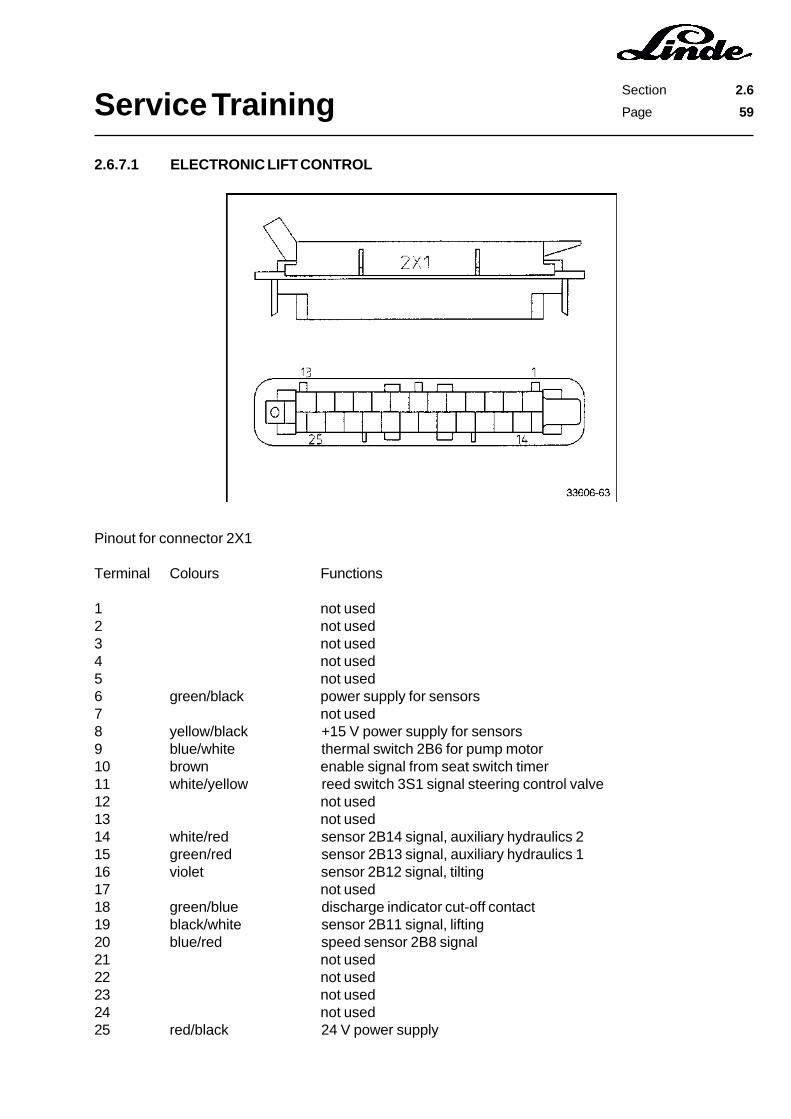
Service TrainingSection 2.6
Page 59
Pinout for connector 2X1
Terminal Colours Functions
1 not used2 not used3 not used4 not used5 not used6 green/black power supply for sensors7 not used8 yellow/black +15 V power supply for sensors9 blue/white thermal switch 2B6 for pump motor10 brown enable signal from seat switch timer11 white/yellow reed switch 3S1 signal steering control valve12 not used13 not used14 white/red sensor 2B14 signal, auxiliary hydraulics 215 green/red sensor 2B13 signal, auxiliary hydraulics 116 violet sensor 2B12 signal, tilting17 not used18 green/blue discharge indicator cut-off contact19 black/white sensor 2B11 signal, lifting20 blue/red speed sensor 2B8 signal21 not used22 not used23 not used24 not used25 red/black 24 V power supply
2.6.7.1 ELECTRONIC LIFT CONTROL
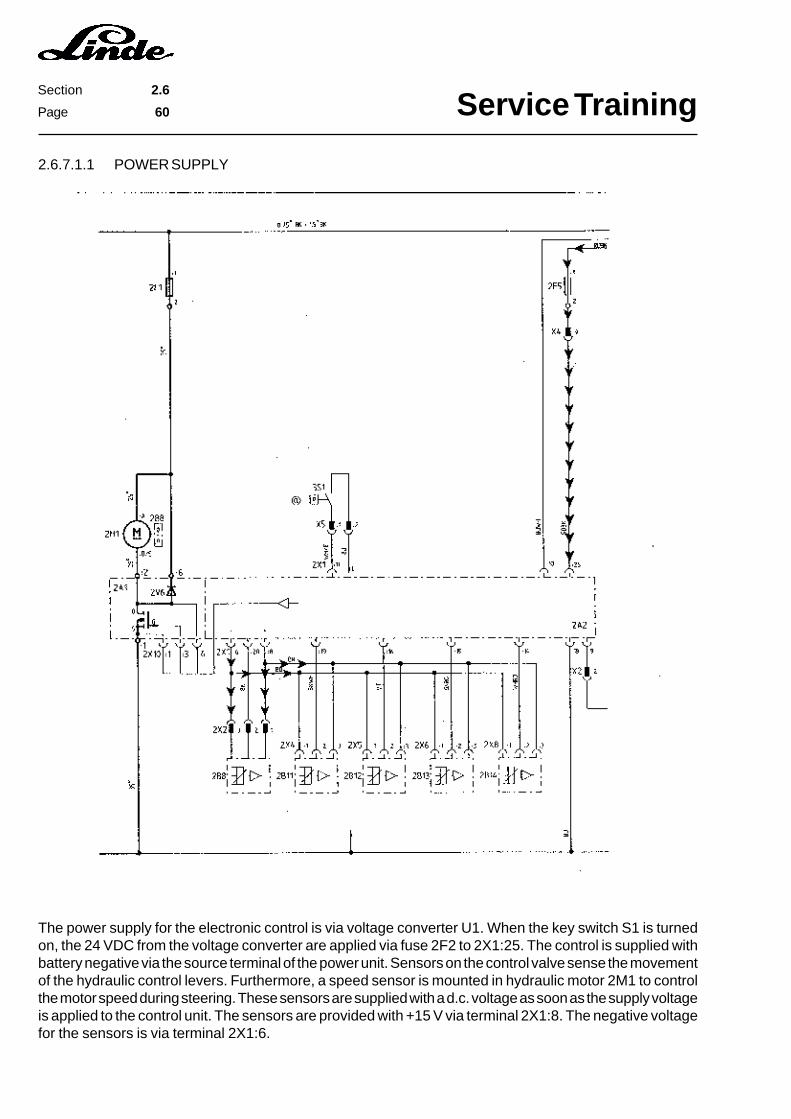
Service TrainingSection 2.6
Page 60
2.6.7.1.1 POWER SUPPLY
The power supply for the electronic control is via voltage converter U1. When the key switch S1 is turnedon, the 24 VDC from the voltage converter are applied via fuse 2F2 to 2X1:25. The control is supplied withbattery negative via the source terminal of the power unit. Sensors on the control valve sense the movementof the hydraulic control levers. Furthermore, a speed sensor is mounted in hydraulic motor 2M1 to controlthe motor speed during steering. These sensors are supplied with a d.c. voltage as soon as the supply voltageis applied to the control unit. The sensors are provided with +15 V via terminal 2X1:8. The negative voltagefor the sensors is via terminal 2X1:6.
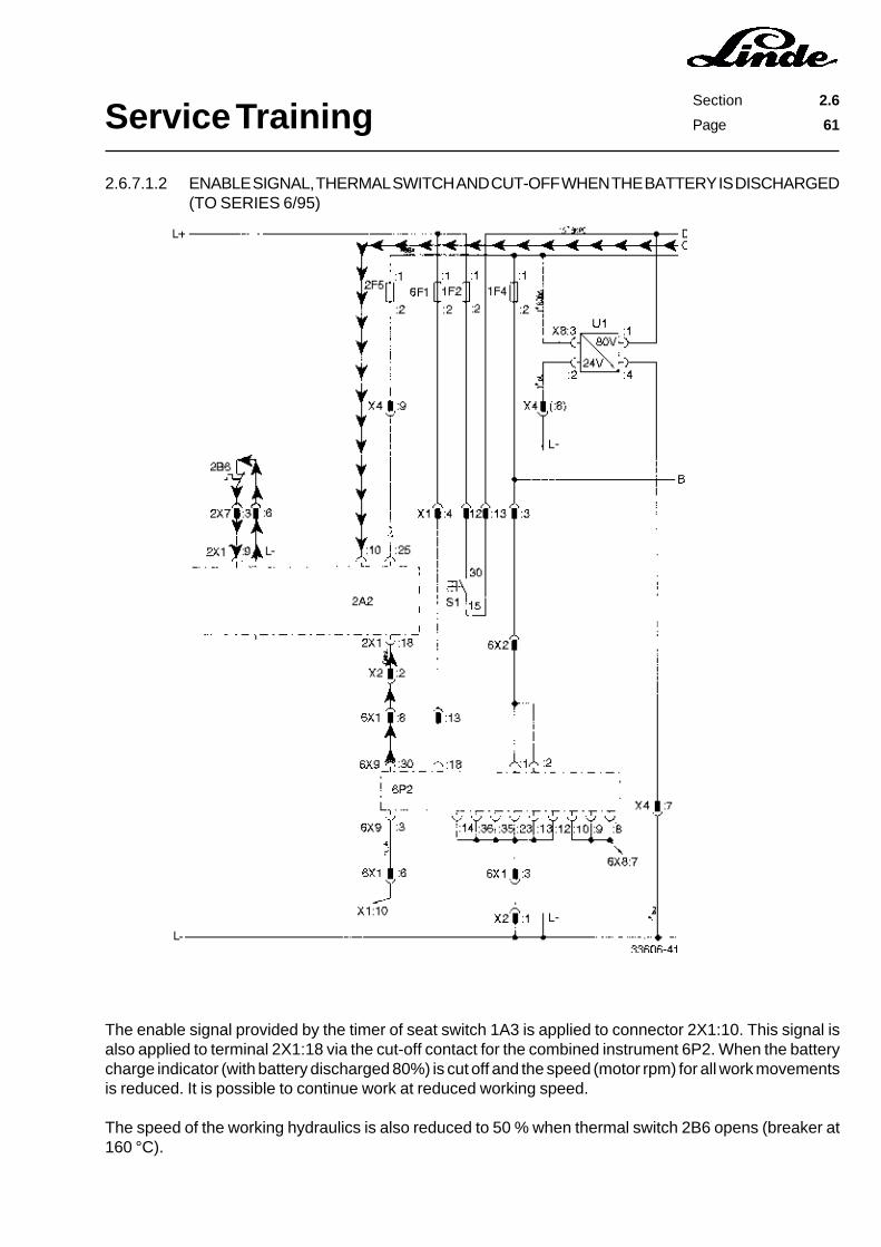
Service TrainingSection 2.6
Page 61
2.6.7.1.2 ENABLE SIGNAL, THERMAL SWITCH AND CUT-OFF WHEN THE BATTERY IS DISCHARGED(TO SERIES 6/95)
The enable signal provided by the timer of seat switch 1A3 is applied to connector 2X1:10. This signal isalso applied to terminal 2X1:18 via the cut-off contact for the combined instrument 6P2. When the batterycharge indicator (with battery discharged 80%) is cut off and the speed (motor rpm) for all work movementsis reduced. It is possible to continue work at reduced working speed.
The speed of the working hydraulics is also reduced to 50 % when thermal switch 2B6 opens (breaker at160 °C).
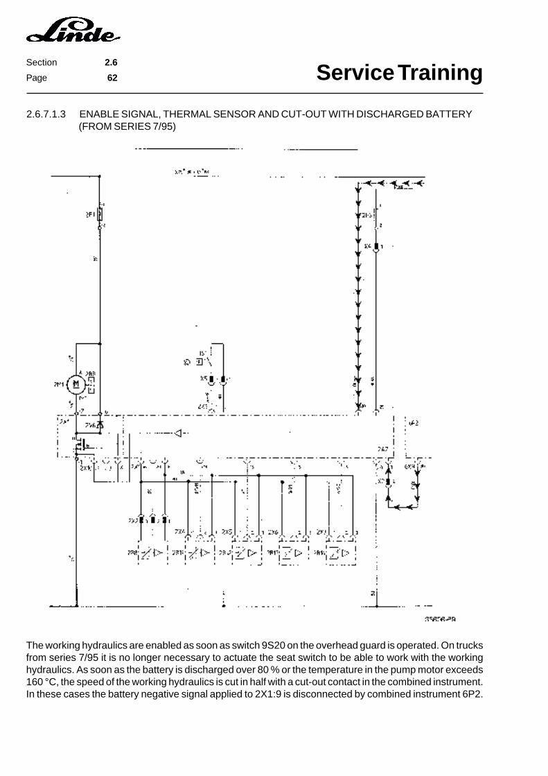
Service TrainingSection 2.6
Page 62
2.6.7.1.3 ENABLE SIGNAL, THERMAL SENSOR AND CUT-OUT WITH DISCHARGED BATTERY(FROM SERIES 7/95)
The working hydraulics are enabled as soon as switch 9S20 on the overhead guard is operated. On trucksfrom series 7/95 it is no longer necessary to actuate the seat switch to be able to work with the workinghydraulics. As soon as the battery is discharged over 80 % or the temperature in the pump motor exceeds160 °C, the speed of the working hydraulics is cut in half with a cut-out contact in the combined instrument.In these cases the battery negative signal applied to 2X1:9 is disconnected by combined instrument 6P2.
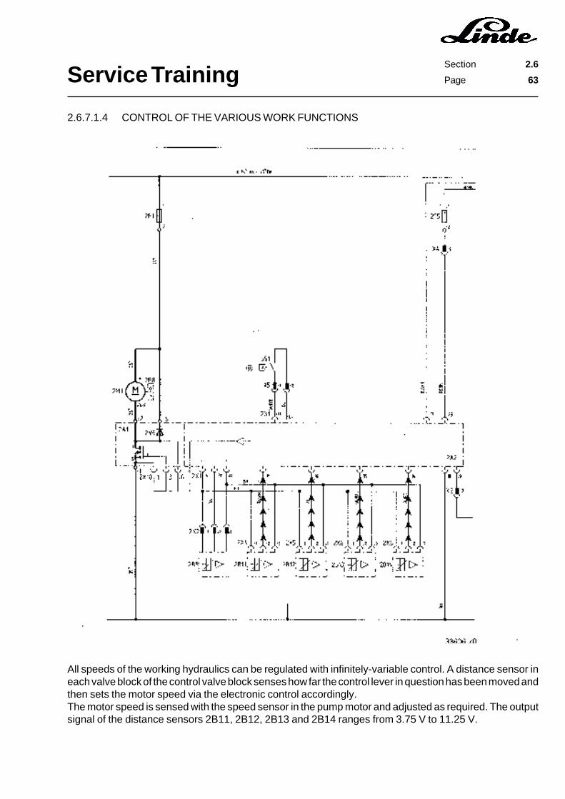
Service TrainingSection 2.6
Page 63
2.6.7.1.4 CONTROL OF THE VARIOUS WORK FUNCTIONS
All speeds of the working hydraulics can be regulated with infinitely-variable control. A distance sensor ineach valve block of the control valve block senses how far the control lever in question has been moved andthen sets the motor speed via the electronic control accordingly.The motor speed is sensed with the speed sensor in the pump motor and adjusted as required. The outputsignal of the distance sensors 2B11, 2B12, 2B13 and 2B14 ranges from 3.75 V to 11.25 V.

Service TrainingSection 2.6
Page 64
2.6.7.1.5 SENSORS IN THE CONTROL VALVE BLOCK
The sensors in the various valve sections work with plunger-type coils. Each sensor contains two identicalcylindrical coils. At the lower part of the control spool is a ferromagnetic anchor which moves in the cylindricalcoils when the control spool is moved. Both cylindric coils are connected in series and they are operatedwith alternate current. The alternate current voltage is created by an internal circuit in the control valve block.The sensors are supplied with 15 Volt at 2X1:8 by the electronic lift control unit. Battery negative is providedfor the sensors via terminal 2X1:6.
Output signals:
Neutral position of control spool 7.5 VExtended control spool max. 3.75 VRetracted control spool max. 11.25 V
Sensor 2B11, lifting output signal at 2X1:19 and 2X1:6Sensor 2B12, tilting output signal at 2X1:16 and 2X1:6Sensor 2B13, auxiliary hydraulics 1 output signal at 2X1:15 and 2X1:6Sensor 2B14, auxiliary hydraulics 2 output signal at 2X1:14 and 2X1:6
These sensors work practically without any friction, and are contained in a tight casing, therefore preventingdust and other foreign matter from entering. Meaning that these sensors have a long service life.
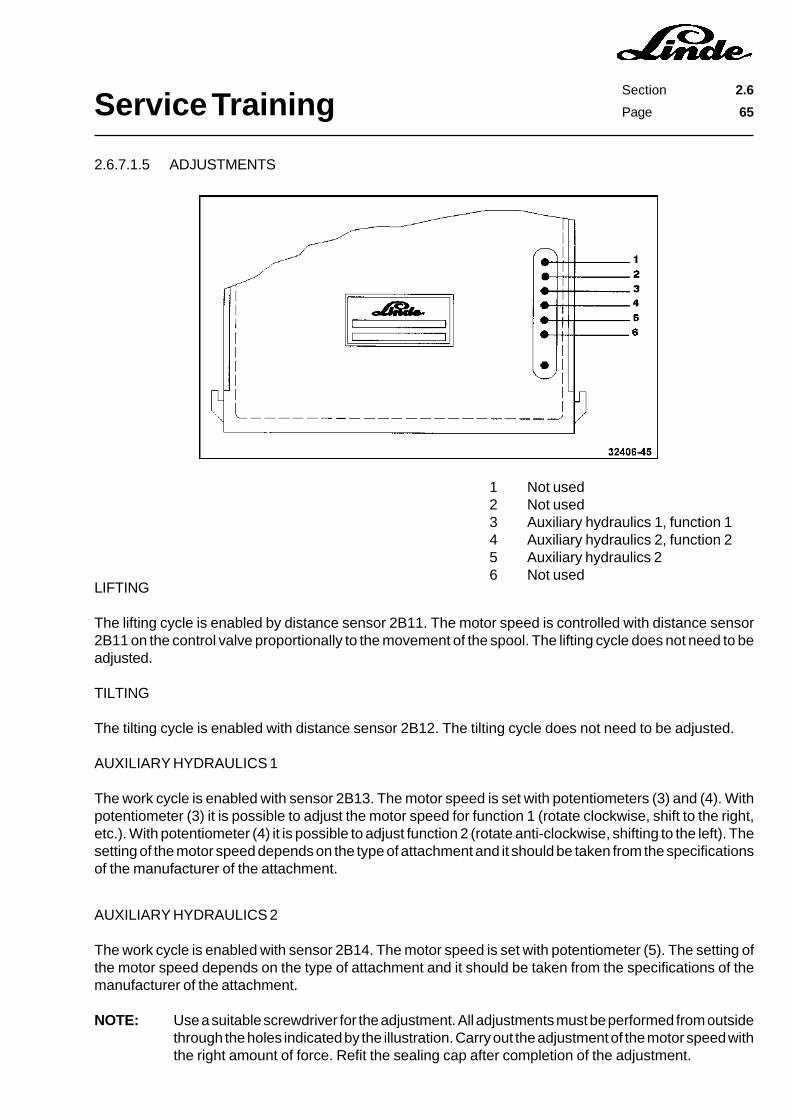
Service TrainingSection 2.6
Page 65
2.6.7.1.5 ADJUSTMENTS
1 Not used2 Not used3 Auxiliary hydraulics 1, function 14 Auxiliary hydraulics 2, function 25 Auxiliary hydraulics 26 Not used
LIFTING
The lifting cycle is enabled by distance sensor 2B11. The motor speed is controlled with distance sensor2B11 on the control valve proportionally to the movement of the spool. The lifting cycle does not need to beadjusted.
TILTING
The tilting cycle is enabled with distance sensor 2B12. The tilting cycle does not need to be adjusted.
AUXILIARY HYDRAULICS 1
The work cycle is enabled with sensor 2B13. The motor speed is set with potentiometers (3) and (4). Withpotentiometer (3) it is possible to adjust the motor speed for function 1 (rotate clockwise, shift to the right,etc.). With potentiometer (4) it is possible to adjust function 2 (rotate anti-clockwise, shifting to the left). Thesetting of the motor speed depends on the type of attachment and it should be taken from the specificationsof the manufacturer of the attachment.
AUXILIARY HYDRAULICS 2
The work cycle is enabled with sensor 2B14. The motor speed is set with potentiometer (5). The setting ofthe motor speed depends on the type of attachment and it should be taken from the specifications of themanufacturer of the attachment.
NOTE: Use a suitable screwdriver for the adjustment. All adjustments must be performed from outsidethrough the holes indicated by the illustration. Carry out the adjustment of the motor speed withthe right amount of force. Refit the sealing cap after completion of the adjustment.

Service TrainingSection 2.6
Page 66
2.6.7.2 CONTROL OF THE STEERING FUNCTION
The series 336 vehicles do not have a separate steering pump motor. The required quantity of hydraulic oilfor the cylinder is taken directly from the working hydraulics pump. In order to ensure that the correct quantityof oil goes to the steering cylinder even when the working hydraulics are being operated, a priority valve forthe steering system is installed in the steering control valve.
As soon as the steering is operated, reed switch 3S1 in the steering control valve is actuated. This switchis connected to the working hydraulics electronics and it lets the pump motor run at 600 rpm. If the workinghydraulics are not in operation, the pump motor speed is controlled with sensor 2B8.
When the steering is operated, the reed contact in the steering control valve connects battery negative to2X1:11.

Service TrainingSection 2.6
Page 67
2.6.7.2.1 OPERATION OF SPEED SENSOR 2B8
Speed sensor 2B8 is supplied with a d.c. voltage of 15 V by the electronics. When the motor rotates, adiaphragm moves in front of the sensor. The sensor output signal alternates constantly from 0 V to 15 V assoon as a segment of the diaphragm is in front of the sensing area of the sensor. In this way the frequencyof the output signal changes with the speed of the motor.
FUNCTIONAL CHECK
Power supply:
- Connect a voltmeter to 2X1:6 and 2X1:8. The supply voltage must be 15 Volt.
Output signal:
- Connect a voltmeter to 2X1:20 and 2X1:6.- Turn on the key switch.- Operate the steering. When the pump motor is running, the output signal must be approx. 5 to 7 Volt.
Adjustment:
The speed sensor 2B8 should be mounted 2 mm from the diaphragm.
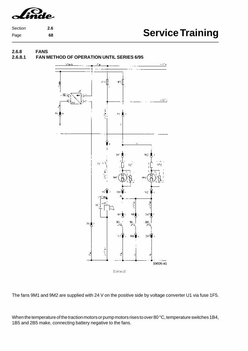
Service TrainingSection 2.6
Page 68
2.6.8 FANS2.6.8.1 FAN METHOD OF OPERATION UNTIL SERIES 6/95
The fans 9M1 and 9M2 are supplied with 24 V on the positive side by voltage converter U1 via fuse 1F5.
When the temperature of the traction motors or pump motors rises to over 80 °C, temperature switches 1B4,1B5 and 2B5 make, connecting battery negative to the fans.
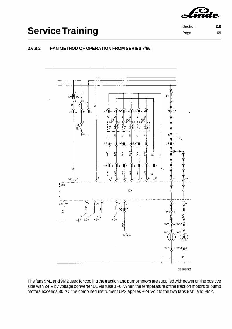
Service TrainingSection 2.6
Page 69
2.6.8.2 FAN METHOD OF OPERATION FROM SERIES 7/95
The fans 9M1 and 9M2 used for cooling the traction and pump motors are supplied with power on the positiveside with 24 V by voltage converter U1 via fuse 1F6. When the temperature of the traction motors or pumpmotors exceeds 80 °C, the combined instrument 6P2 applies +24 Volt to the two fans 9M1 and 9M2.
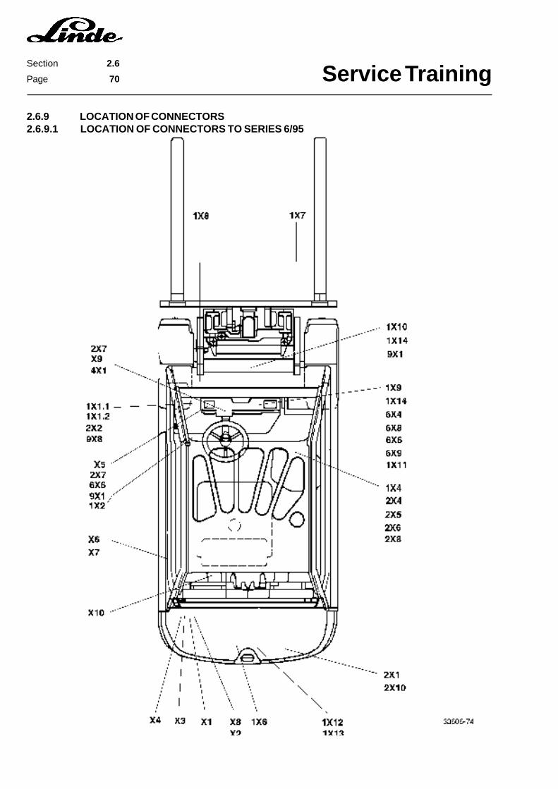
Service TrainingSection 2.6
Page 70
2.6.9 LOCATION OF CONNECTORS2.6.9.1 LOCATION OF CONNECTORS TO SERIES 6/95

Service TrainingSection 2.6
Page 71
Connector Location FunctionX1 15-pin Electrical system, left side Connector to main wire harnessX2 6-pin Electrical system, left side Connector to main wire harnessX3 12-pin Electrical system, left side Connector to main wire harnessX4 15-pin Electrical system, left side Connector to main wire harnessX5 2-pin On steering control valve Terminal on steering reed contactX6 4-pin In rear chassis, left side Curve sensorX7 4-pin In rear chassis, left side Curve sensorX8 6-pin Electrical system, left side Voltage converterX9 3-pin Under steering column cover Overhead guard switchX10 On rear battery compartment Battery plug1X1.14-pin In motor compartment, left side Amplifier for speed sensor1X1.24-pin In motor compartment, left side Amplifier for speed sensor1X2 3-pin In motor compartment, left side Fan 9M21X4 3-pin On hydraulic control valve Parking brake switch1X6 3-pin Electrical system, left side Current actual value sender1X7 8-pin On RH traction motor Thermal switch, brush switch1X8 8-pin On LH traction motor Thermal switch, brush switch1X9 4-pin Under RH switch cover at console Single-pedal directional switch1X10 6-pin Under floor groupAccelerator sensor1X11 2-pin Under RH switch cover at console Single-pedal directional switch, Baker1X12 6-pin Electrical system, centre Connector for traction power unit1X13 42-pin Electrical system, centre Connector for traction control unit1X14 3-pin Under floor group Brake pedal switch2X1 25-pin Electrical system, right side Connector for lift power unit2X2 3-pin On pump motor Pump motor speed sensor2X4 3-pin On hydraulic control valve Lift sensor2X5 3-pin On hydraulic control valve Tilt sensor2X6 3-pin On hydraulic control valve Auxiliary hydraulics sensor 12X7 3-pin On pump motor Thermal switch, brush wear2X8 3-pin On hydraulic control valve Auxiliary hydraulics sensor 22X10 6-pin Electrical system, right side Connector for lift power unit4X1 2-pin Under steering column cover Horn switch6X4 12-pin under RH switch cover at console Brush monitor6X6 4-pin under LH switch cover at console Diagnostic connector6X8 12-pin under RH switch cover at console Brush monitor6X9 36-pin under RH switch cover at console Combined instrument9X1 3-pin Motor compartment, centre Fan 9M19X8 3-pin Motor compartment, left side Fan 9M2

Service TrainingSection 2.6
Page 72
2.6.9.2 LOCATION OF CONNECTORS FROM SERIES 7/95
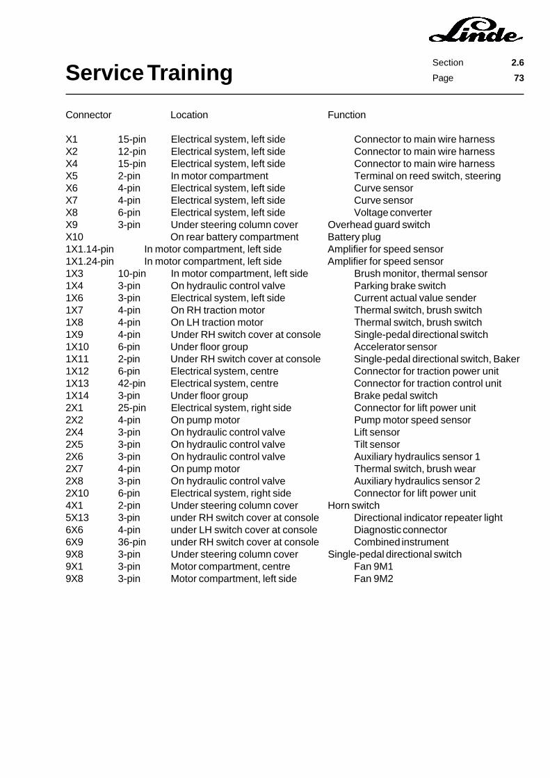
Service TrainingSection 2.6
Page 73
Connector Location Function
X1 15-pin Electrical system, left side Connector to main wire harnessX2 12-pin Electrical system, left side Connector to main wire harnessX4 15-pin Electrical system, left side Connector to main wire harnessX5 2-pin In motor compartment Terminal on reed switch, steeringX6 4-pin Electrical system, left side Curve sensorX7 4-pin Electrical system, left side Curve sensorX8 6-pin Electrical system, left side Voltage converterX9 3-pin Under steering column cover Overhead guard switchX10 On rear battery compartment Battery plug1X1.14-pin In motor compartment, left side Amplifier for speed sensor1X1.24-pin In motor compartment, left side Amplifier for speed sensor1X3 10-pin In motor compartment, left side Brush monitor, thermal sensor1X4 3-pin On hydraulic control valve Parking brake switch1X6 3-pin Electrical system, left side Current actual value sender1X7 4-pin On RH traction motor Thermal switch, brush switch1X8 4-pin On LH traction motor Thermal switch, brush switch1X9 4-pin Under RH switch cover at console Single-pedal directional switch1X10 6-pin Under floor group Accelerator sensor1X11 2-pin Under RH switch cover at console Single-pedal directional switch, Baker1X12 6-pin Electrical system, centre Connector for traction power unit1X13 42-pin Electrical system, centre Connector for traction control unit1X14 3-pin Under floor group Brake pedal switch2X1 25-pin Electrical system, right side Connector for lift power unit2X2 4-pin On pump motor Pump motor speed sensor2X4 3-pin On hydraulic control valve Lift sensor2X5 3-pin On hydraulic control valve Tilt sensor2X6 3-pin On hydraulic control valve Auxiliary hydraulics sensor 12X7 4-pin On pump motor Thermal switch, brush wear2X8 3-pin On hydraulic control valve Auxiliary hydraulics sensor 22X10 6-pin Electrical system, right side Connector for lift power unit4X1 2-pin Under steering column cover Horn switch5X13 3-pin under RH switch cover at console Directional indicator repeater light6X6 4-pin under LH switch cover at console Diagnostic connector6X9 36-pin under RH switch cover at console Combined instrument9X8 3-pin Under steering column cover Single-pedal directional switch9X1 3-pin Motor compartment, centre Fan 9M19X8 3-pin Motor compartment, left side Fan 9M2

Service TrainingSection 2.6
Page 74
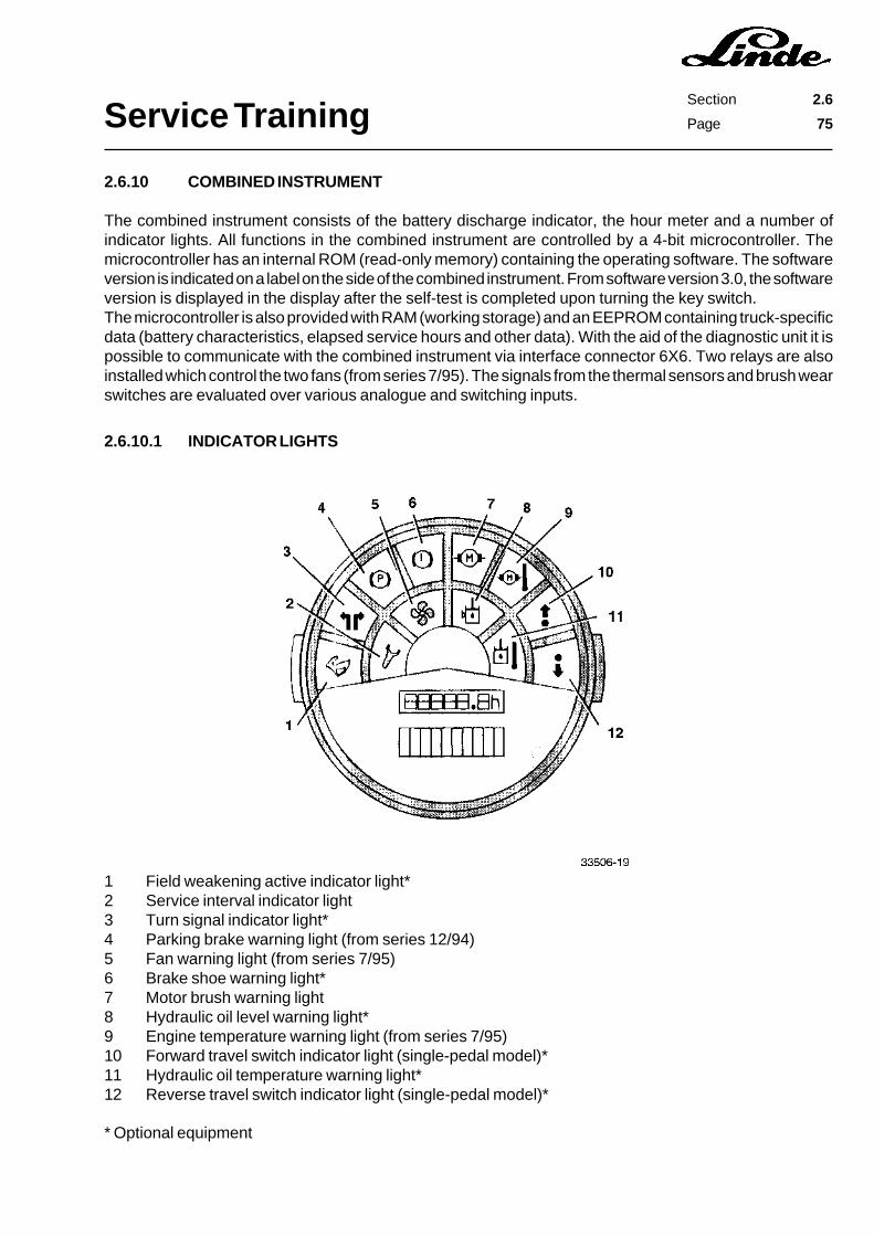
Service TrainingSection 2.6
Page 75
2.6.10 COMBINED INSTRUMENT
The combined instrument consists of the battery discharge indicator, the hour meter and a number ofindicator lights. All functions in the combined instrument are controlled by a 4-bit microcontroller. Themicrocontroller has an internal ROM (read-only memory) containing the operating software. The softwareversion is indicated on a label on the side of the combined instrument. From software version 3.0, the softwareversion is displayed in the display after the self-test is completed upon turning the key switch.The microcontroller is also provided with RAM (working storage) and an EEPROM containing truck-specificdata (battery characteristics, elapsed service hours and other data). With the aid of the diagnostic unit it ispossible to communicate with the combined instrument via interface connector 6X6. Two relays are alsoinstalled which control the two fans (from series 7/95). The signals from the thermal sensors and brush wearswitches are evaluated over various analogue and switching inputs.
1 Field weakening active indicator light*2 Service interval indicator light3 Turn signal indicator light*4 Parking brake warning light (from series 12/94)5 Fan warning light (from series 7/95)6 Brake shoe warning light*7 Motor brush warning light8 Hydraulic oil level warning light*9 Engine temperature warning light (from series 7/95)10 Forward travel switch indicator light (single-pedal model)*11 Hydraulic oil temperature warning light*12 Reverse travel switch indicator light (single-pedal model)*
2.6.10.1 INDICATOR LIGHTS
* Optional equipment
Service TrainingSection 2.6
Page 76
2.6.10.1.1 FIELD WEAKENING ACTIVE INDICATOR LIGHT (OPTION)
With this option this lamp signals that the field weakening function is activated. The field weakening effectis produced by connecting resistors in parallel to the field winding of the traction motors. This reduces themagnetic flux in the field winding, while simultaneously increasing the speed of the motors. The fieldweakening must be turned on and off depending on the load on the motors as the torque of the motors isreduced with the increase in speed.
2.6.10.1.2 TURN SIGNAL INDICATOR LIGHT (FROM SERIES 7/95)
With the lighting option this lamp indicates that the turn signals are switched on. It is controlled directly overthe two 12 Volt terminals on the turn signal lights. A bidirectional optocoupler in the combined instrumentdecouples the two signals from the turn signals lights. The connection is made with plug 5X13 under the LHswitch cover.
2.6.10.1.3 PARKING BRAKE WARNING LIGHT (FROM SERIES 12/94)
When the parking brake is applied, the parking brake switch 1S4 is opened. This cuts off the battery negativesignal applied to 6X9:23 and the lamp is illuminated.
2.6.10.1.4 BRAKE SHOE WARNING LIGHT (OPTION)
2.6.10.1.5 MOTOR BRUSH WARNING LIGHT
A brush wear switch is installed on each motor brush. When a brush is worn down to 60 % of its original length,the respective brush switch is activated. The brush wear is signalled by the illumination of the lamp.Information regarding which motor is affected is also shown on the LCD display (from series 7/95).
1 = RH traction motor2 = LH traction motor3 = Pump motor
The display of the motor number alternates every 5 seconds with the display of the elapsed service hours.The fact that the brush wear limit of a motor has been reached is stored in the combined instrument withthe number of the motor in question and the elapsed service hours. This information can be read, if necessary,with the diagnostic unit.
2.6.10.1.6 ENGINE TEMPERATURE WARNING LIGHT (FROM SERIES 7/95)
If the temperature of one of the three motors exceeds 140 °C, the lamp is illuminated to indicate overheatingof the motor in question. As in the case of the indication of the brush wear limit, the motor number is shownin the LCD display and it is stored in the combined instrument together with the elapsed service hours.

Service TrainingSection 2.6
Page 77
2.6.10.1.7 TRAVEL DIRECTION INDICATOR (OPTION)
With the single-pedal option the chosen direction of travel is signalled by the two indicator lights. With thisfunction the battery negative signal from the travel direction switch to the electronic traction unit is evaluatedby the combined instrument.
2.6.10.1.8 HYDRAULIC OIL TEMPERATURE WARNING LIGHT (OPTION)
With this option, a thermal switch located in the hydraulic oil reservoir is activated when the oil temperatureis too high. A battery negative signal is applied to terminal 6X9:25, which illuminates the light.
2.6.10.1.9 HYDRAULIC OIL LEVEL WARNING LIGHT (OPTION)
When the hydraulic oil level is too low, a battery negative signal is applied to terminal 6X9:24 of the combinedinstrument by a float switch.
2.6.10.1.10 FAN WARNING LIGHT (FROM SERIES 7/95)
When the temperature in a motor exceeds 140 °C, this light is illuminated in addition to the motor temperaturewarning light to signal that the operation of the respective fan should be checked.
2.6.10.1.11 SERVICE INTERVAL INDICATOR LIGHT
The illumination of the service interval indicator light signals to the operator that an inspection or lubricationservice is due. The interval can be modified in certain areas. The modification and the reset is done with thediagnostic unit.
Service TrainingSection 2.6
Page 78
2.6.10.2 BATTERY DISCHARGE INDICATOR
The battery discharge indicator consists of 10 LEDs (7 green, 1 orange and 2 red). Depending on the batterystate of charge, the row of illuminated LEDs goes off from battery fully charged (right green LED) to batterydischarged (both red LEDs flashing). When the two red LEDs flash, the speed of the working hydraulics isreduced by 50 %.
The condition of a battery is always reflected in its discharge voltage gradient. In the case of the Lindedischarge indicator, the battery voltage is measured and from this value the voltage of the cells is deduced.The cell voltage drops as the battery discharges. The cell voltage is also influenced by the momentary currentconsumption. The surge in cell voltage with a load is lower with a charged battery than with a dischargedone. The registration of battery discharge is based on the voltage surges measured over a period of time.
The discharge voltage gradient varies with the type, age and discharge period of the battery. Variousdischarge characteristic curves are stored in the operating software of the combined instrument for varioustypes of batteries. The correct curve must be chosen for the battery installed. The battery type can be modifiedwith menu item 21.
1 Standard wet cell Varta (factory setting)2 Standard wet cell Deta3 Performance enhanced battery4 Gel battery
The discharge period and the age of the battery also affect the discharge characteristic. The programmeddischarge characteristic can be shifted in certain ranges in order to show the correct discharge informationon the display.
When the battery discharge reaches 80 percent, the speed of the working hydraulics is reduced to warn theoperator that the battery must be charged. This value can be increased to a residual capacity of 40 percent.
Depending on the type of application and battery, the discharge indicator must be optimised. An optimisationis done with the diagnostic unit using the following menu items:
21 Battery type22 Upper discharge characteristic23 Cut-out point
The changes should be done in the smallest possible steps. The installed battery type should be programmedfirst. Then a fine adjustment can be performed with menu item 22 (upper discharge characteristic), whichcorresponds to the adjusting potentiometer (range A to E) on the Curtis discharge indicator, and with menuitem 23 (cut-out point).

Service TrainingSection 2.6
Page 79
The table below serves as a programming aid for the various types of batteries and applications. Dependingon the application and type of battery, menu numbers 22 and 23 can be altered according to the followingtable. A detailed description regarding the application of the diagnostic unit in connection with the combinedinstrument is given in section 2.6.11.
The battery discharge indicator is reset to "battery fully charged" by the increase in cell voltage after chargingof the battery. This cell voltage is programmed to be 2.09 V per cell as standard value. This value can bemodified with menu item 22. The cell voltage value must be applied for a certain period of time after turningon the key switch before the discharge indicator is reset. When the truck is delivered, this value is set to 0.1min. This time can be changed with menu item 24.
Type of Application Time for Reduction Change in Menu Change in Menuand Battery No. 22. No. 23
Particularly heavy duty Too early Reduce IncreaseBattery charging under4 hrs required
Particularly light duty Too late Increase IncreaseBattery charging oncea week
Trucks with many options Too late Increase Increase(basic loads e.g.heater, etc.)
Performance enhanced Too late Increase by 0.03 V IncreasePzS battery
PzV battery Too late Increase by 0.06 V Increase
CSM battery Too late Increase by 0.09 V Increase

Service TrainingSection 2.6
Page 80
2.6.11 LINDE DIAGNOSTIC UNIT
In future Linde will use more microprocessor-based controls. For this reason Linde has developed thediagnostic unit P/N 390 360 5405. This special tool and measuring unit (WM 136) can now be ordered fromparts Service.
The Linde diagnostic unit is used for communication (programming, initiaiization and queries) with themicroprocessor-based controls of Linde components provided with an ISO Interface (DIN/ISO 9141). Thediagnostic unit contains terminal software which allows communication with the unit in question through theISO interface.
The internal operating software is integrated in an EPROM and it controls the input, output and display. Noadaption of the operating software to newly developed or modified components is required.
The diagnostic unit is equipped with an LCD (liquid crystal display) with 4 lines, each consisting of 20 digits,and a foil keyboard with 20 keys. A cable supplied with the diagnostic unit is used to connect the unit to theLinde component in question.
Power is supplied by four 1.5 V round cells R6 or by electrical system of the Linde truck. The installed roundcells are tested each times the diagnostic unit is switched on.
If no key is touched, the diagnostic unit is automatically switched off after 80 sec. to spare the round cells.If visibility is pour, the display can be illuminated pressing the appropriate key.
The contrast of the LCD display can be set with a potentiometer in the diagnostic unit.

Service TrainingSection 2.6
Page 81
DATENNEU
ENTER
CE
0 - 9+ -
RESET
EIN
AUS
LICHT
Switching on thediagnostic unit
Switching off thediagnostic unit
Resettingdiagnostic unit
Display lighting
Data transmission
No function
Input keys
Start a new input
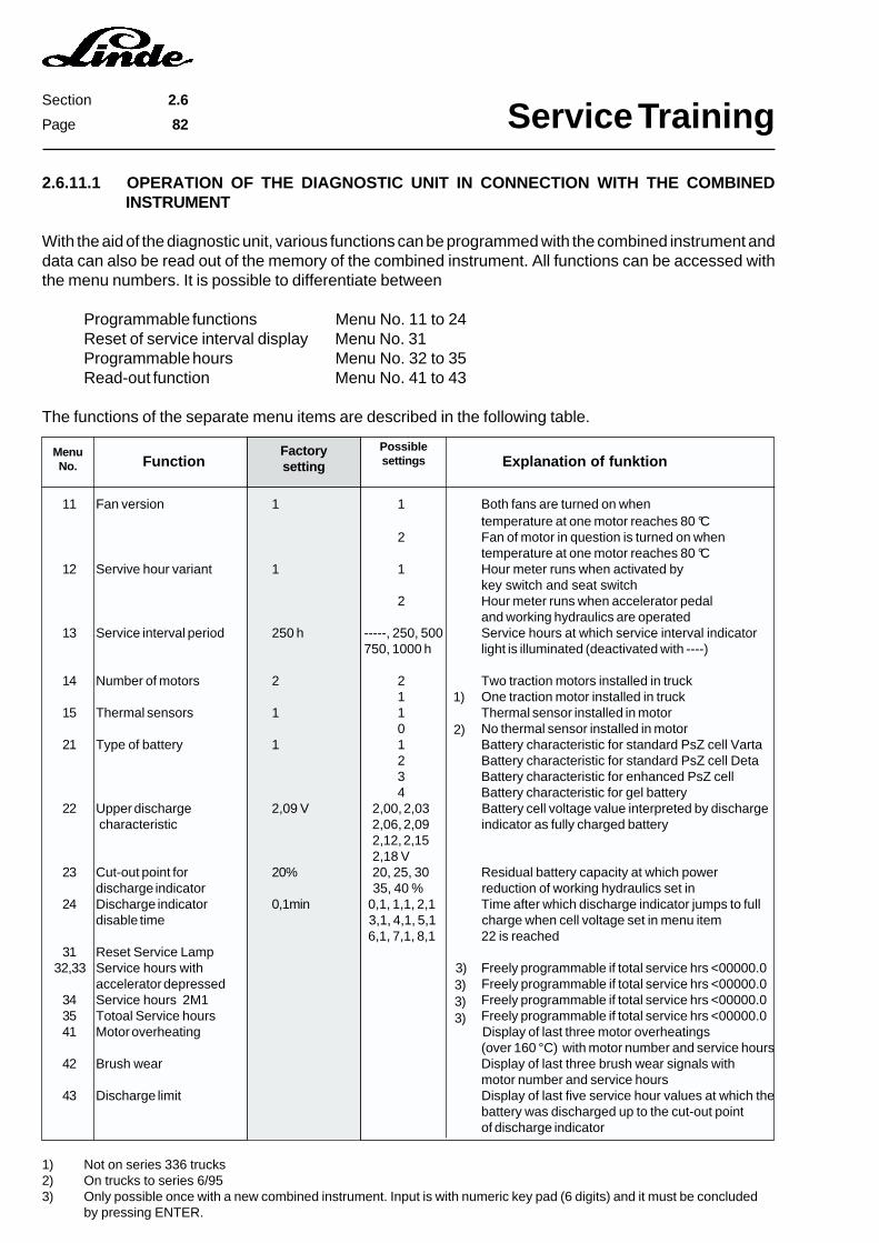
Service TrainingSection 2.6
Page 82
2.6.11.1 OPERATION OF THE DIAGNOSTIC UNIT IN CONNECTION WITH THE COMBINEDINSTRUMENT
With the aid of the diagnostic unit, various functions can be programmed with the combined instrument anddata can also be read out of the memory of the combined instrument. All functions can be accessed withthe menu numbers. It is possible to differentiate between
Programmable functions Menu No. 11 to 24Reset of service interval display Menu No. 31Programmable hours Menu No. 32 to 35Read-out function Menu No. 41 to 43
The functions of the separate menu items are described in the following table.
Function Explanation of funktionFactorysetting
MenuNo.
Possiblesettings
3)3)3)3)
1)
2)
1) Not on series 336 trucks2) On trucks to series 6/953) Only possible once with a new combined instrument. Input is with numeric key pad (6 digits) and it must be concluded
by pressing ENTER.
11 Fan version 1 1 Both fans are turned on whentemperature at one motor reaches 80 °C
2 Fan of motor in question is turned on whentemperature at one motor reaches 80 °C
12 Servive hour variant 1 1 Hour meter runs when activated bykey switch and seat switch
2 Hour meter runs when accelerator pedaland working hydraulics are operated
13 Service interval period 250 h -----, 250, 500 Service hours at which service interval indicator750, 1000 h light is illuminated (deactivated with ----)
14 Number of motors 2 2 Two traction motors installed in truck1 One traction motor installed in truck
15 Thermal sensors 1 1 Thermal sensor installed in motor0 No thermal sensor installed in motor
21 Type of battery 1 1 Battery characteristic for standard PsZ cell Varta2 Battery characteristic for standard PsZ cell Deta3 Battery characteristic for enhanced PsZ cell4 Battery characteristic for gel battery
22 Upper discharge 2,09 V 2,00, 2,03 Battery cell voltage value interpreted by discharge characteristic 2,06, 2,09 indicator as fully charged battery
2,12, 2,152,18 V
23 Cut-out point for 20% 20, 25, 30 Residual battery capacity at which powerdischarge indicator 35, 40 % reduction of working hydraulics set in
24 Discharge indicator 0,1min 0,1, 1,1, 2,1 Time after which discharge indicator jumps to fulldisable time 3,1, 4,1, 5,1 charge when cell voltage set in menu item
6,1, 7,1, 8,1 22 is reached31 Reset Service Lamp
32,33 Service hours with Freely programmable if total service hrs <00000.0accelerator depressed Freely programmable if total service hrs <00000.0
34 Service hours 2M1 Freely programmable if total service hrs <00000.035 Totoal Service hours Freely programmable if total service hrs <00000.041 Motor overheating Display of last three motor overheatings
(over 160 °C) with motor number and service hours42 Brush wear Display of last three brush wear signals with
motor number and service hours43 Discharge limit Display of last five service hour values at which the
battery was discharged up to the cut-out pointof discharge indicator
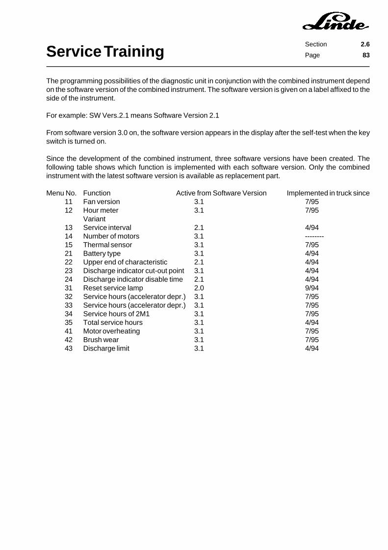
Service TrainingSection 2.6
Page 83
The programming possibilities of the diagnostic unit in conjunction with the combined instrument dependon the software version of the combined instrument. The software version is given on a label affixed to theside of the instrument.
For example: SW Vers.2.1 means Software Version 2.1
From software version 3.0 on, the software version appears in the display after the self-test when the keyswitch is turned on.
Since the development of the combined instrument, three software versions have been created. Thefollowing table shows which function is implemented with each software version. Only the combinedinstrument with the latest software version is available as replacement part.
Menu No. Function Active from Software Version Implemented in truck since11 Fan version 3.1 7/9512 Hour meter 3.1 7/95
Variant13 Service interval 2.1 4/9414 Number of motors 3.1 --------15 Thermal sensor 3.1 7/9521 Battery type 3.1 4/9422 Upper end of characteristic 2.1 4/9423 Discharge indicator cut-out point 3.1 4/9424 Discharge indicator disable time 2.1 4/9431 Reset service lamp 2.0 9/9432 Service hours (accelerator depr.) 3.1 7/9533 Service hours (accelerator depr.) 3.1 7/9534 Service hours of 2M1 3.1 7/9535 Total service hours 3.1 4/9441 Motor overheating 3.1 7/9542 Brush wear 3.1 7/9543 Discharge limit 3.1 4/94
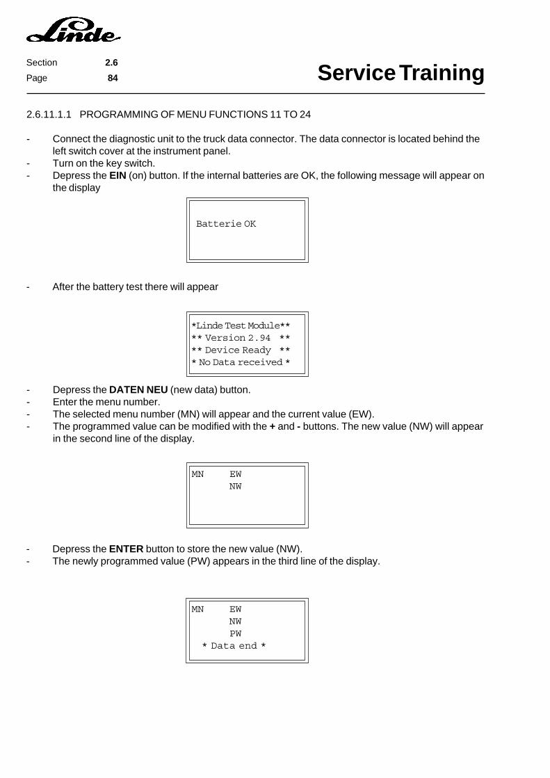
Service TrainingSection 2.6
Page 84
Batterie OK
*Linde Test Module**
** Version 2.94 **
** Device Ready **
* No Data received *
- Depress the ENTER button to store the new value (NW).- The newly programmed value (PW) appears in the third line of the display.
MN EW
NW
- After the battery test there will appear
MN EW
NW
PW
* Data end *
- Depress the DATEN NEU (new data) button.- Enter the menu number.- The selected menu number (MN) will appear and the current value (EW).- The programmed value can be modified with the + and - buttons. The new value (NW) will appear
in the second line of the display.
2.6.11.1.1 PROGRAMMING OF MENU FUNCTIONS 11 TO 24
- Connect the diagnostic unit to the truck data connector. The data connector is located behind theleft switch cover at the instrument panel.
- Turn on the key switch.- Depress the EIN (on) button. If the internal batteries are OK, the following message will appear on
the display

Service TrainingSection 2.6
Page 85
Batterie OK
*Linde Test Module**
** Version 2.94 **
** Device Ready **
* No Data received *
- Depress the ENTER button.- The service interval indicator is reset and in the third line of the display there appears the operating
hours at which the service interval indicator will next be illuminated.
- Depress the DATEN NEU (new data) button.- Enter menu number 31.- The selected menu number will appear and also the current service interval setting (factory setting
is 250 hrs).- The service hours at which the service interval indicator was last reset are shown in the second line
of the display.
31 250
XXXXXX
- After the battery test there will appear
31 250
XXXXXX
XXXXXX
* Data end *
2.6.11.1.2 RESETTING THE SERVICE INTERVAL INDICATOR WITH MENU FUNCTION 31
- Connect the diagnostic unit to the truck data connector. The data connector is located behind theleft switch cover at the instrument panel.
- Turn on the key switch.- Depress the EIN (on) button. If the internal batteries are OK, the following message will appear on
the display
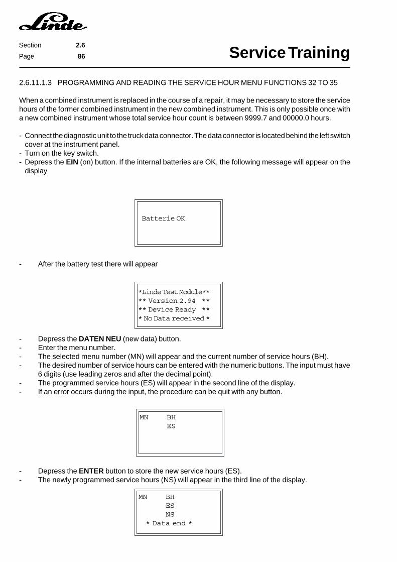
Service TrainingSection 2.6
Page 86
Batterie OK
*Linde Test Module**
** Version 2.94 **
** Device Ready **
* No Data received *
- Depress the ENTER button to store the new service hours (ES).- The newly programmed service hours (NS) will appear in the third line of the display.
- After the battery test there will appear
MN BH
ES
NS
* Data end *
2.6.11.1.3 PROGRAMMING AND READING THE SERVICE HOUR MENU FUNCTIONS 32 TO 35
When a combined instrument is replaced in the course of a repair, it may be necessary to store the servicehours of the former combined instrument in the new combined instrument. This is only possible once witha new combined instrument whose total service hour count is between 9999.7 and 00000.0 hours.
- Connect the diagnostic unit to the truck data connector. The data connector is located behind the left switchcover at the instrument panel.
- Turn on the key switch.- Depress the EIN (on) button. If the internal batteries are OK, the following message will appear on the
display
MN BH
ES
- Depress the DATEN NEU (new data) button.- Enter the menu number.- The selected menu number (MN) will appear and the current number of service hours (BH).- The desired number of service hours can be entered with the numeric buttons. The input must have
6 digits (use leading zeros and after the decimal point).- The programmed service hours (ES) will appear in the second line of the display.- If an error occurs during the input, the procedure can be quit with any button.
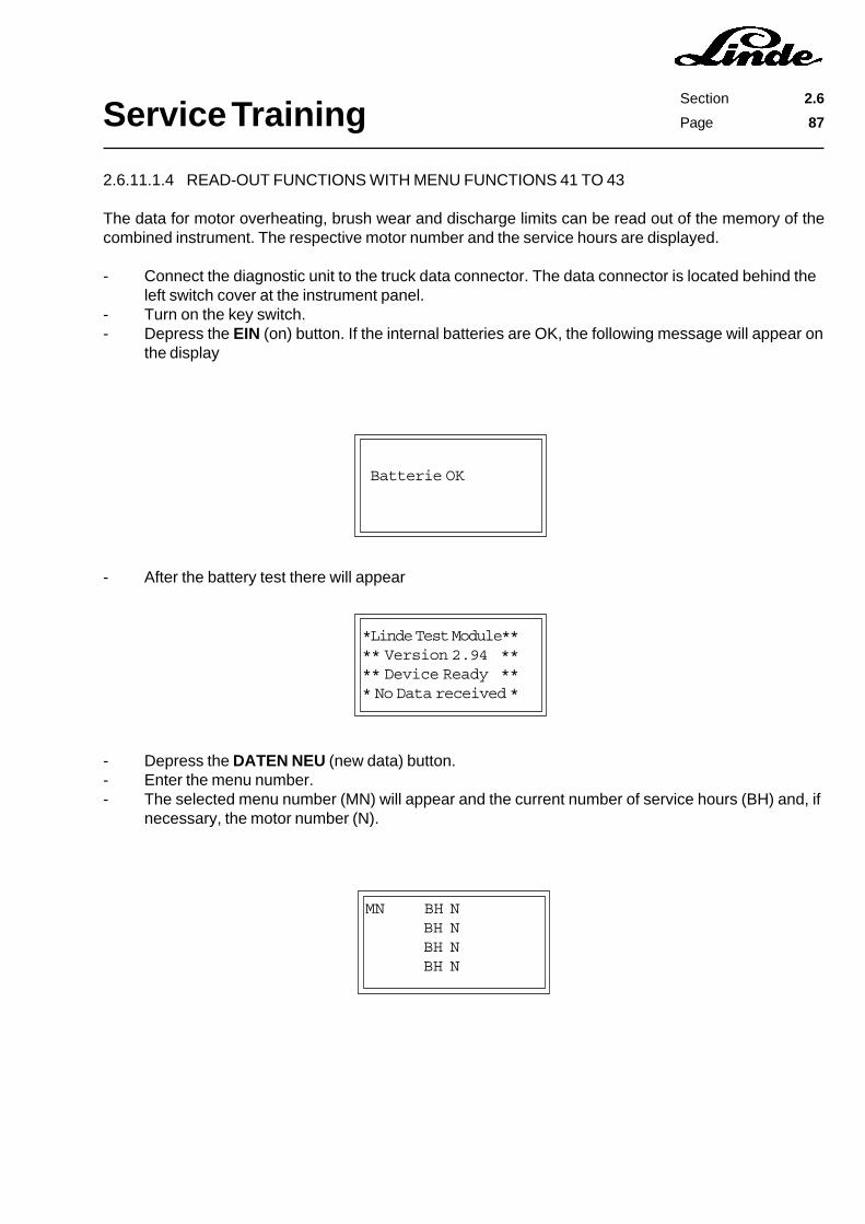
Service TrainingSection 2.6
Page 87
Batterie OK
*Linde Test Module**
** Version 2.94 **
** Device Ready **
* No Data received *
MN BH N
BH N
BH N
BH N
2.6.11.1.4 READ-OUT FUNCTIONS WITH MENU FUNCTIONS 41 TO 43
The data for motor overheating, brush wear and discharge limits can be read out of the memory of thecombined instrument. The respective motor number and the service hours are displayed.
- Connect the diagnostic unit to the truck data connector. The data connector is located behind theleft switch cover at the instrument panel.
- Turn on the key switch.- Depress the EIN (on) button. If the internal batteries are OK, the following message will appear on
the display
- After the battery test there will appear
- Depress the DATEN NEU (new data) button.- Enter the menu number.- The selected menu number (MN) will appear and the current number of service hours (BH) and, if
necessary, the motor number (N).
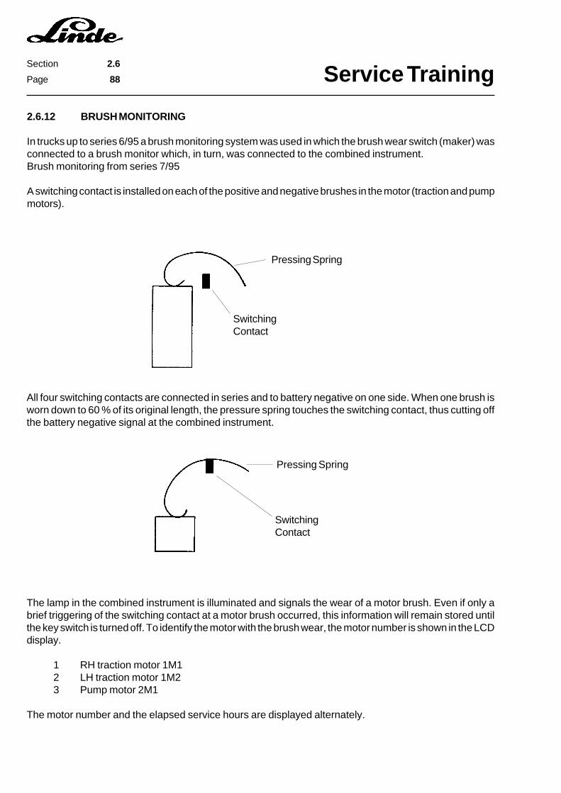
Service TrainingSection 2.6
Page 88
2.6.12 BRUSH MONITORING
In trucks up to series 6/95 a brush monitoring system was used in which the brush wear switch (maker) wasconnected to a brush monitor which, in turn, was connected to the combined instrument.Brush monitoring from series 7/95
A switching contact is installed on each of the positive and negative brushes in the motor (traction and pumpmotors).
SwitchingContact
Pressing Spring
All four switching contacts are connected in series and to battery negative on one side. When one brush isworn down to 60 % of its original length, the pressure spring touches the switching contact, thus cutting offthe battery negative signal at the combined instrument.
Pressing Spring
SwitchingContact
The lamp in the combined instrument is illuminated and signals the wear of a motor brush. Even if only abrief triggering of the switching contact at a motor brush occurred, this information will remain stored untilthe key switch is turned off. To identify the motor with the brush wear, the motor number is shown in the LCDdisplay.
1 RH traction motor 1M12 LH traction motor 1M23 Pump motor 2M1
The motor number and the elapsed service hours are displayed alternately.
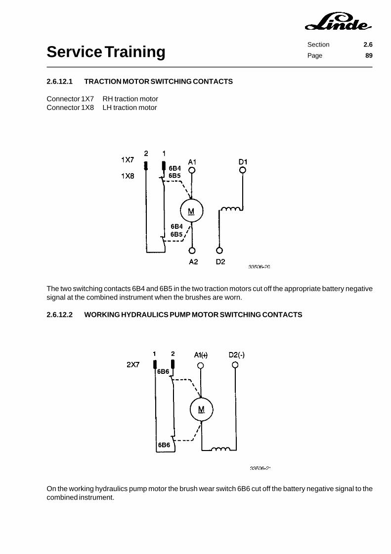
Service TrainingSection 2.6
Page 89
2.6.12.1 TRACTION MOTOR SWITCHING CONTACTS
Connector 1X7 RH traction motorConnector 1X8 LH traction motor
The two switching contacts 6B4 and 6B5 in the two traction motors cut off the appropriate battery negativesignal at the combined instrument when the brushes are worn.
2.6.12.2 WORKING HYDRAULICS PUMP MOTOR SWITCHING CONTACTS
On the working hydraulics pump motor the brush wear switch 6B6 cut off the battery negative signal to thecombined instrument.
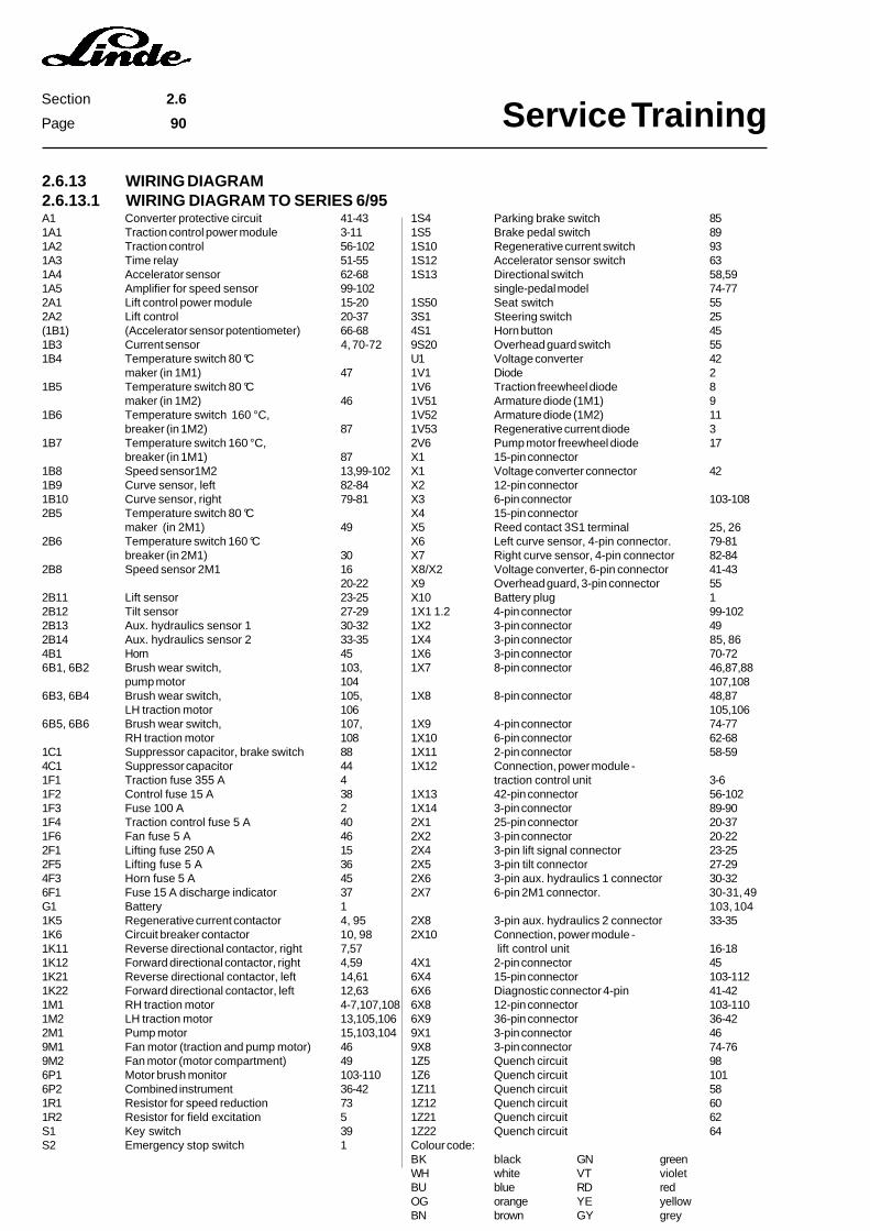
Service TrainingSection 2.6
Page 90
2.6.13 WIRING DIAGRAM2.6.13.1 WIRING DIAGRAM TO SERIES 6/95
1S4 Parking brake switch 851S5 Brake pedal switch 891S10 Regenerative current switch 931S12 Accelerator sensor switch 631S13 Directional switch 58,59
single-pedal model 74-771S50 Seat switch 553S1 Steering switch 254S1 Horn button 459S20 Overhead guard switch 55U1 Voltage converter 421V1 Diode 21V6 Traction freewheel diode 81V51 Armature diode (1M1) 91V52 Armature diode (1M2) 111V53 Regenerative current diode 32V6 Pump motor freewheel diode 17X1 15-pin connectorX1 Voltage converter connector 42X2 12-pin connectorX3 6-pin connector 103-108X4 15-pin connectorX5 Reed contact 3S1 terminal 25, 26X6 Left curve sensor, 4-pin connector. 79-81X7 Right curve sensor, 4-pin connector 82-84X8/X2 Voltage converter, 6-pin connector 41-43X9 Overhead guard, 3-pin connector 55X10 Battery plug 11X1 1.2 4-pin connector 99-1021X2 3-pin connector 491X4 3-pin connector 85, 861X6 3-pin connector 70-721X7 8-pin connector 46,87,88
107,1081X8 8-pin connector 48,87
105,1061X9 4-pin connector 74-771X10 6-pin connector 62-681X11 2-pin connector 58-591X12 Connection, power module -
traction control unit 3-61X13 42-pin connector 56-1021X14 3-pin connector 89-902X1 25-pin connector 20-372X2 3-pin connector 20-222X4 3-pin lift signal connector 23-252X5 3-pin tilt connector 27-292X6 3-pin aux. hydraulics 1 connector 30-322X7 6-pin 2M1 connector. 30-31, 49
103, 1042X8 3-pin aux. hydraulics 2 connector 33-352X10 Connection, power module -
lift control unit 16-184X1 2-pin connector 456X4 15-pin connector 103-1126X6 Diagnostic connector 4-pin 41-426X8 12-pin connector 103-1106X9 36-pin connector 36-429X1 3-pin connector 469X8 3-pin connector 74-761Z5 Quench circuit 981Z6 Quench circuit 1011Z11 Quench circuit 581Z12 Quench circuit 601Z21 Quench circuit 621Z22 Quench circuit 64Colour code:BK black GN greenWH white VT violetBU blue RD redOG orange YE yellowBN brown GY grey
A1 Converter protective circuit 41-431A1 Traction control power module 3-111A2 Traction control 56-1021A3 Time relay 51-551A4 Accelerator sensor 62-681A5 Amplifier for speed sensor 99-1022A1 Lift control power module 15-202A2 Lift control 20-37(1B1) (Accelerator sensor potentiometer) 66-681B3 Current sensor 4, 70-721B4 Temperature switch 80 °C
maker (in 1M1) 471B5 Temperature switch 80 °C
maker (in 1M2) 461B6 Temperature switch 160 °C,
breaker (in 1M2) 871B7 Temperature switch 160 °C,
breaker (in 1M1) 871B8 Speed sensor1M2 13,99-1021B9 Curve sensor, left 82-841B10 Curve sensor, right 79-812B5 Temperature switch 80 °C
maker (in 2M1) 492B6 Temperature switch 160 °C
breaker (in 2M1) 302B8 Speed sensor 2M1 16
20-222B11 Lift sensor 23-252B12 Tilt sensor 27-292B13 Aux. hydraulics sensor 1 30-322B14 Aux. hydraulics sensor 2 33-354B1 Horn 456B1, 6B2 Brush wear switch, 103,
pump motor 1046B3, 6B4 Brush wear switch, 105,
LH traction motor 1066B5, 6B6 Brush wear switch, 107,
RH traction motor 1081C1 Suppressor capacitor, brake switch 884C1 Suppressor capacitor 441F1 Traction fuse 355 A 41F2 Control fuse 15 A 381F3 Fuse 100 A 21F4 Traction control fuse 5 A 401F6 Fan fuse 5 A 462F1 Lifting fuse 250 A 152F5 Lifting fuse 5 A 364F3 Horn fuse 5 A 456F1 Fuse 15 A discharge indicator 37G1 Battery 11K5 Regenerative current contactor 4, 951K6 Circuit breaker contactor 10, 981K11 Reverse directional contactor, right 7,571K12 Forward directional contactor, right 4,591K21 Reverse directional contactor, left 14,611K22 Forward directional contactor, left 12,631M1 RH traction motor 4-7,107,1081M2 LH traction motor 13,105,1062M1 Pump motor 15,103,1049M1 Fan motor (traction and pump motor) 469M2 Fan motor (motor compartment) 496P1 Motor brush monitor 103-1106P2 Combined instrument 36-421R1 Resistor for speed reduction 731R2 Resistor for field excitation 5S1 Key switch 39S2 Emergency stop switch 1
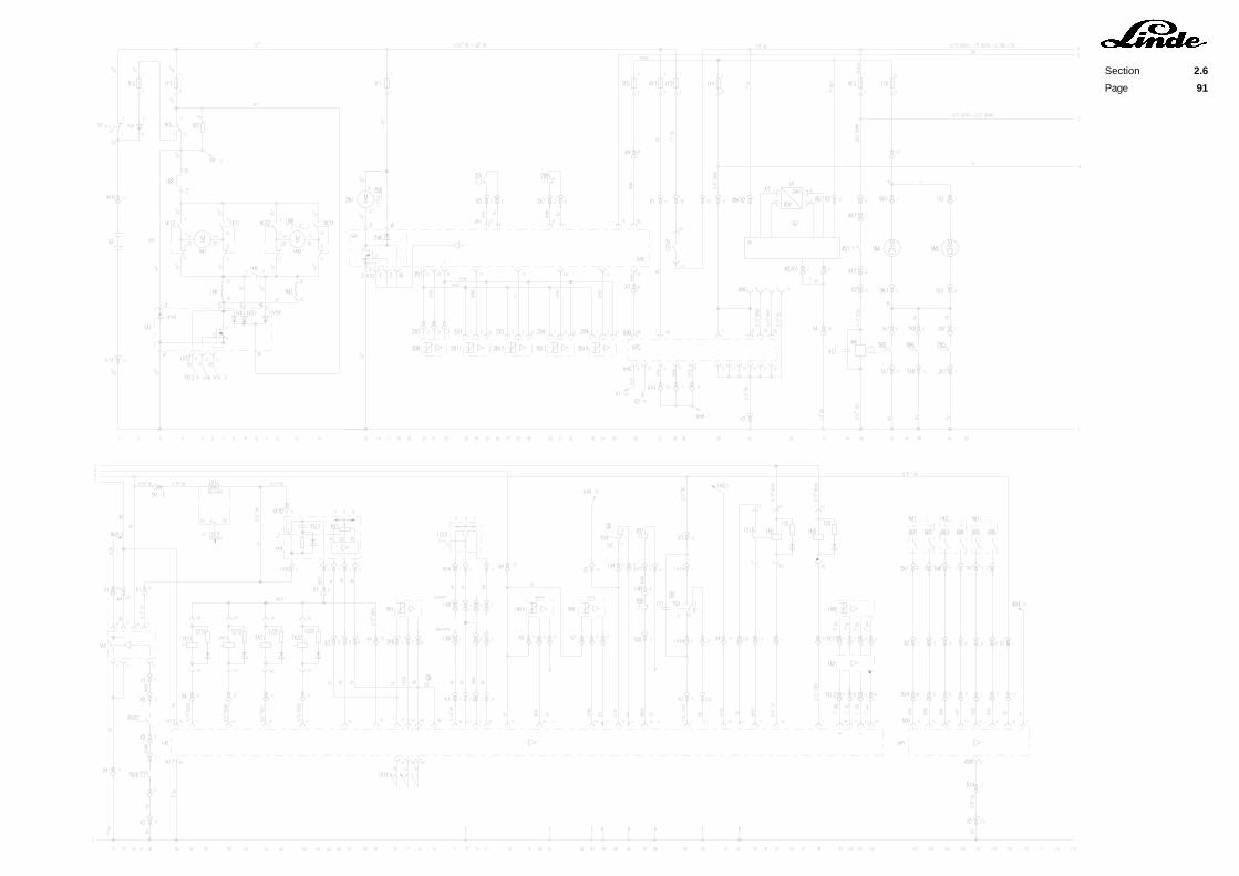
Section 2.6
Page 91


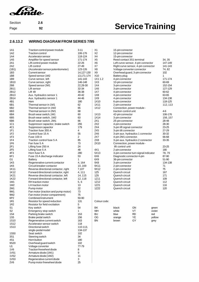
Service TrainingSection 2.6
Page 92
2.6.13.2 WIRING DIAGRAM FROM SERIES 7/95
1A1 Traction control power module 3-111A2 Traction control 106-1761A4 Accelerator sensor 118-1241A5 Amplifier for speed sensor 171-1742A1 Lift control power module 22-262A2 Lift control 27-49(1B1) (Accelerator sensor potentiometer) 123-1261B3 Current sensor 14,127-1301B8 Speed sensor 1M2 13,171-1741B9 Curve sensor, left 141-1431B10 Curve sensor, right 146-1482B8 Speed sensor 2M1 22,28-302B11 Lift sensor 32-342B12 Lift tilt 36-382B13 Aux. hydraulics sensor 1 40-422B14 Aux. hydraulics sensor 1 44-464B1 Horn 1806B1 Thermal sensor in 1M1 626B2 Thermal sensorr in 1M2 656B3 Thermal sensorr in 2M1 686B4 Brush wear switch,1M1 606B5 Brush wear switch, 1M2 636B6 Brush wear switch, 2M1 661C1 Suppressor capacitor, brake switch 2554C1 Suppressor capacitor 1791F1 Traction fuse 355 A 41F2 Control fuse 15 A 551F3 Fuse 100 A 21F4 Traction control fuse 5 A 851F6 Fan fuse 5 A 732F1 Lifting fuse 250 A 242F5 Lifting fuse 5 A 484F3 Horn fuse 5 A 2806F1 Fuse 15 A discharge indicator 53G1 Battery 11K5 Regenerative current contactor 4, 1641K6 Circuit breaker contactor 10, 1691K11 Reverse directional contactor, right 7,1071K12 Forward directional contactor, right 4, 1111K21 Reverse directional contactor, left 14, 1151K22 Forward directional contactor, left 12, 1181M1 RH traction motor 5, 61M2 LH traction motor 132M1 Pump motor 229M1 Fan motor (traction and pump motor) 739M2 Fan motor (motor compartment) 756P2 Combined instrument 50-901R1 Resistor for speed reduction 1311R2 Resistor for field excitation 5S1 Key switch 54S2 Emergency stop switch 11S4 Parking brake switch 1531S5 Brake pedal switch 1561S10 Regenerative current switch 1631S12 Accelerator sensor switch 1181S13 Directional switch 110-113,
single-pedal model 134-1371S50 Seat switch 1023S1 Steering switch 344S1 Horn button 1809S20 Overhead guard switch 102U1 Voltage converter 77-791V6 Traction freewheel diode 81V51 Armature diode (1M1) 91V52 Armature diode (1M2) 111V53 Regenerative current diode 32V6 Pump motor freewheel diode 25
X1 15-pin connectorX2 12-pin connectorX4 15-pin connectorX5 Reed contact 3S1 terminal 34, 35X6 Left curve sensor, 4-pin connector 147-149X7 Right curve sensor, 4-pin connector 141-143X8 Voltage converter connector 74, 82X9 Overhead guard, 3-pin connector 102X10 Battery plug 11X1 1.2 4-pin connector 171-1741X3 10-pin connector 60-691X4 3-pin connector 152-1541X6 3-pin connector 127-1291X7 4-pin connector 60-621X8 4-pin connector 63-651X9 4-pin connector 134-1381X10 6-pin connector 118-1251X11 2-pin connector 112, 1131X12 Connection, power module -
traction control unit 4-61X13 42-pin connector 106-1761X14 3-pin connector 156, 1572X1 25-pin connector 28-482X2 4-pin connector 28-302X4 3-pin lift signal connector 23-252X5 3-pin tilt connector 27-292X6 3-pin aux. hydraulics 1 connector 30-322X7 4-pin 2M1 connector. 66-682X8 3-pin aux. hydraulics 2 connector 33-352X10 Connection, power module -
lift control unit 23-254X1 2-pin connector 1805X13 3-pin connector turn signal indicator 78, 796X6 Diagnostic connector 4-pin 87-906X9 36-pin connector 51-909X8 3-pin connector 134-1389X11 2-pin connector 719X12 2-pin connector 751Z5 Quench circuit 1671Z6 Quench circuit 1711Z11 Quench circuit 1091Z12 Quench circuit 1121Z21 Quench circuit 1161Z22 Quench circuit 120
Colour code:
BK black GN greenWH white VT violetBU blue RD redOG orange YE yellowBN brown GY grey
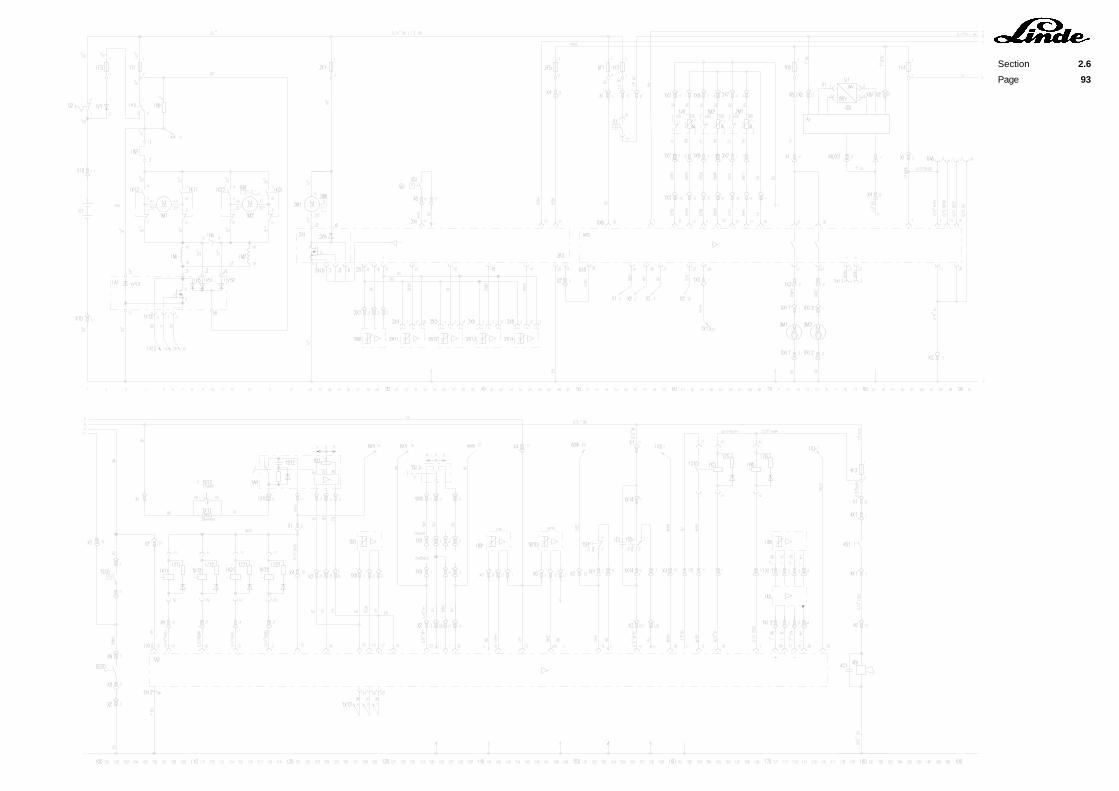
Section 2.6
Page 93

Service TrainingSection 2.7
Page 1
2.7 HYDRAULIC SYSTEM
2.7.1 HYDRAULIC PUMP MOTOR
Type: DC compound-wound motorModel: GF 144-14/4.3Voltage: 80 V, 200 A, 2550 rpmPower: 13.5 kW S3 15%Type of protection: IP00/23Insulation class: FCarbon brushes: 12.5x40x40 mm with dust grooveAdmissible wear: down to 16 mmEquipment: Motor brush monitor - thermal switch to series 6/95; thermal sensor from series
7/95, speed sensor
2.7.2 RENEWING THE HYDRAULIC PUMP MOTOR BRUSHES
- Tilt the overhead guard to the 2nd detent.- Remove the hydraulic pump motor brushes.- Lift up the brush springs.- Pull the brushes out of their guides.- Renew the brushes.
2.7.3 REMOVING THE HYDRAULIC PUMP UNIT
- Tilt the overhead guard to the 2nd detent.- Loosen the hose clamp on the hydraulic reservoir and disconnect the suction line.- Screw off the hydraulic pump supply line P at the steering control valve.- Remove the air duct.- Disconnect the connector 2X7 from the pump motor to the main cable harness.- Disconnect the speed sensor connector 2X2.- Remove the cover on top of the sensor transmitter.- Screw an eyebolt into the motor shaft.- Lift the hydraulic pump unit out of the vehicle with suitable lifting equipment.
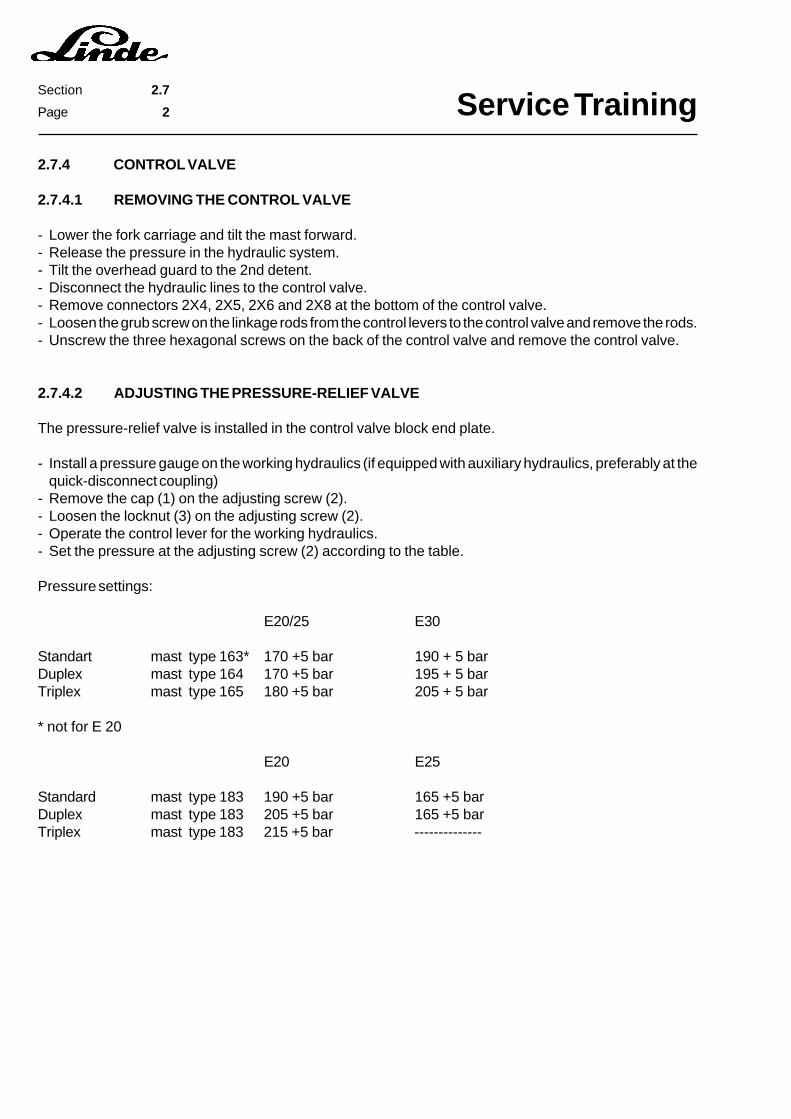
Service TrainingSection 2.7
Page 2
2.7.4 CONTROL VALVE
2.7.4.1 REMOVING THE CONTROL VALVE
- Lower the fork carriage and tilt the mast forward.- Release the pressure in the hydraulic system.- Tilt the overhead guard to the 2nd detent.- Disconnect the hydraulic lines to the control valve.- Remove connectors 2X4, 2X5, 2X6 and 2X8 at the bottom of the control valve.- Loosen the grub screw on the linkage rods from the control levers to the control valve and remove the rods.- Unscrew the three hexagonal screws on the back of the control valve and remove the control valve.
2.7.4.2 ADJUSTING THE PRESSURE-RELIEF VALVE
The pressure-relief valve is installed in the control valve block end plate.
- Install a pressure gauge on the working hydraulics (if equipped with auxiliary hydraulics, preferably at thequick-disconnect coupling)
- Remove the cap (1) on the adjusting screw (2).- Loosen the locknut (3) on the adjusting screw (2).- Operate the control lever for the working hydraulics.- Set the pressure at the adjusting screw (2) according to the table.
Pressure settings:
E20/25 E30
Standart mast type 163* 170 +5 bar 190 + 5 barDuplex mast type 164 170 +5 bar 195 + 5 barTriplex mast type 165 180 +5 bar 205 + 5 bar
* not for E 20
E20 E25
Standard mast type 183 190 +5 bar 165 +5 barDuplex mast type 183 205 +5 bar 165 +5 barTriplex mast type 183 215 +5 bar --------------
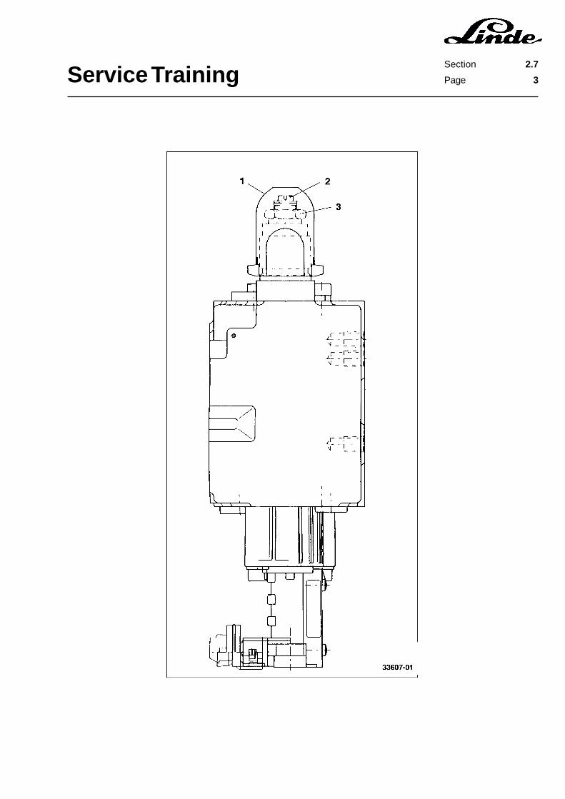
Service TrainingSection 2.7
Page 3
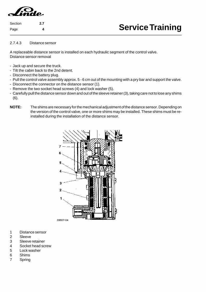
Service TrainingSection 2.7
Page 4
2.7.4.3 Distance sensor
A replaceable distance sensor is installed on each hydraulic segment of the control valve.Distance sensor removal
- Jack up and secure the truck.- Tilt the cabin back to the 2nd detent.- Disconnect the battery plug.- Pull the control valve assembly approx. 5 - 6 cm out of the mounting with a pry bar and support the valve.- Disconnect the connector on the distance sensor (1).- Remove the two socket head screws (4) and lock washer (5).- Carefully pull the distance sensor down and out of the sleeve retainer (3), taking care not to lose any shims
(6).
NOTE: The shims are necessary for the mechanical adjustment of the distance sensor. Depending onthe version of the control valve, one or more shims may be installed. These shims must be re-installed during the installation of the distance sensor.
1 Distance sensor2 Sleeve3 Sleeve retainer4 Socket head screw5 Lock washer6 Shims7 Spring

Service TrainingSection 2.7
Page 5
Installation:
- Carefully position the distance sensor (1) on the sleeve retainer (3) or spring (7), being sure that the numberand location of the shims is correct. Retain the original connector position.
- Screw in and hand tighten the two socket head screws (4) and lock washers (5).- Install the plug on the distance sensor.- Remove the support at the control valve and lower the control valve.
The control of the distance sensor output signal is described in the section 2.6 on the electrical system.

Service TrainingSection 2.7
Page 6
2.7.5 WORKING AND STEERING HYDRAULICS CIRCUIT DIAGRAM
A WORKING HYDRAULICS
1 Hydraulic oil reservoir.2 Suction filter (15 µm) 0.25 bar3 Breather filter4 Hydraulic pump 22 cu cm/rev5 Electric motor6 Control valve7 5/3 way valve for double auxiliary hydraulics8 6/3 way valve for single auxiliary hydraulics9 6/3 way valve for tilting10 6/3 way valve for lifting11 Restrictor12 Make-up valve13 Maximum pressure valve14 Pressure holding valve15 Tilt jack16 Brake lower valve17 Pipe safety valve18-1 Lift jack, standard mast18-2 Lift jack, duplex mast18-3 Lift jack, triplex mast
B Steering hydraulics
19 Steering control valve20 7/3 way valve21 Non-return valve22 Shock valve23 Make-up valve24 Restrictor25 3/3 way valve26 Maximum pressure valve27 Power steering control28 Steering jack

Service TrainingSection 2.7
Page 7

Service TrainingSection 2.7
Page 8
Service TrainingSection 2.9
Page 1
2.9 OPTIONS
2.9.1 LIGHTING, WIPERS AND HEATER
2.9.1.1 VOLTAGE CONVERTER
The options such as heater, lighting or wipers operate with a power supply of 12 V. The battery voltage of80 V is reduced to this value by the voltage converter.
The voltage converter functions according to the chopper principle. This means that the battery voltage isconverted into a 20 kHz rectangular voltage. This rectangular voltage is reduced by a transformer andsubsequently rectified.
The input side is galvanically separated from the output side and is not connected to ground. The output isnot regulated, i.e. the output voltage varies with input voltage and load. The output voltage is indicated bya light emitting diode. The output fuse makes the converter short-proof. There is a false pole protection atthe input side of the converter.
CAUTION: The maximum power of the voltage converter is 200 W. If the required power is higher, a secondvoltage converter must be installed. This voltage converter must not be connected in parallelto the existing one. The two voltage converters must be separated on the secondary side at thefuse socket.
Maximum load for a voltage converter (200 Watt) corresponds to
- 3 working lights with 55 W each
or
- 2 working lights with 55 W each and front and rear windscreen wipers
or
- truck lighting and traffic options
Specifications:
Type: G80G12/16WDC0,2Input voltage: 80 V ± 10%Output voltage: 12 VPower: 200 WattOutput fuse: 15 Ampere slow-blowingInput fuse: 4 Ampere slow-blowingAmbient temperature: -10 °C to +55 °CEfficiency: 80% to 85%Max. housing temperature: 45 °C with max. load

Service TrainingSection 2.9
Page 2
2.9.1.2 SWITCHES
Description:
1 Working light switch 9S1Switch lighting
2 Working light switch 9S2Switch lighting
3 Front wiper switch 9S3Switch lighting
4 Rear wiper switch 9S3Switch lighting
5 Light switch 5S11Switch lighting
6 Hazard warning flasher switch 5H19Switch lighting
NOTE: The switches can be arranged in different sequences, depending on the version.

Service TrainingSection 2.9
Page 3
2.9.1.3 FUSE BOXES
Top view of fuse boxes I and II
Fuse OutputA - F
Fuse Input1 - 6
Fuse Input1 - 6
Fuse OutputA - F
Wire harnesses:
1 Front wiper1a Rear wiper2 Lighting3 Working lights4 Voltage converter5 Voltage converter
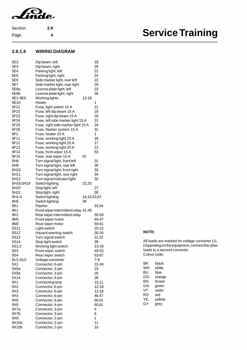
Service TrainingSection 2.9
Page 4
2.9.1.4 WIRING DIAGRAM
5E2 Dip beam, left 195E3 Dip beam, right 205E4 Parking light, left 215E5 Parking light, right 245E6 Side marker light, rear left 225E7 Side marker light, rear right 255E8a License plate light, left 235E8b License plate light, right 269E1-9E6 Working lights 12-189E10 Heater 15F21 Fuse, light switch 15 A 215F22 Fuse, left dip beam 15 A 195F23 Fuse, right dip beam 15 A 205F24 Fuse, left side marker light 15 A 215F25 Fuse, right side marker light 15 A 245F26 Fuse, flasher system 15 A 319F1 Fuse, heater 20 A 19F11 Fuse, working light 20 A 169F12 Fuse, working light 20 A 179F13 Fuse, working light 20 A 139F14 Fuse, front wiper 15 A 539F15 Fuse, rear wiper 15 A 675H8 Turn signal light, front left 315H9 Turn signal light, rear left 305H10 Turn signal light, front right 335H11 Turn signal light, rear right 345H12 Turn signal indicator light 325H18,5H19 Switch lighting 22,235H20 Stop light, left 275H21 Stop light, right 289H1-4 Switch lighting 14,15,53,679H5 Switch lighting 395K1 Flasher 33,349K1 Front wiper intermittent relay 41-459K2 Rear wiper intermittent relay 55-599M1 Front wiper motor 45-479M2 Rear wiper motor 59-615S11 Light switch 20-225S12 Hazard warning switch 30-345S13 Turn signal switch 31,325S14 Stop light switch 289S1,2 Working light switch 13-189S3 Front wiper switch 49-539S4 Rear wiper switch 63-679U1,9U2 Voltage converter 7-95X1 Connector, 6-pin 22-345X5a Connector, 3-pin 235X5b Connector, 3-pin 265X14 Connector, 6-pin 289X1 Connecting strip 10,119X2 Connector, 6-pin 12-189X3 Connector, 6-pin 12-189X4 Connector, 6-pin 46,479X5 Connector, 6-pin 60,619X6 Connector, 4-pin 60,619X7a Connector, 3-pin 49X7b Connector, 3-pin 69X9 Connector, 2-pin 19X10a Connector, 2-pin 119X10b Connector, 2-pin 10
NOTE:
All loads are marked on voltage converter U1.Depending on the equipment, connect the otherloads to a second converter.Colour code:
BK blackWH whiteBU blueOG orangeBN brownGN greenVT violetRD redYE yellowGY grey
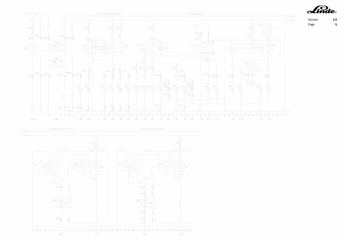
Section 2.9
Page 5

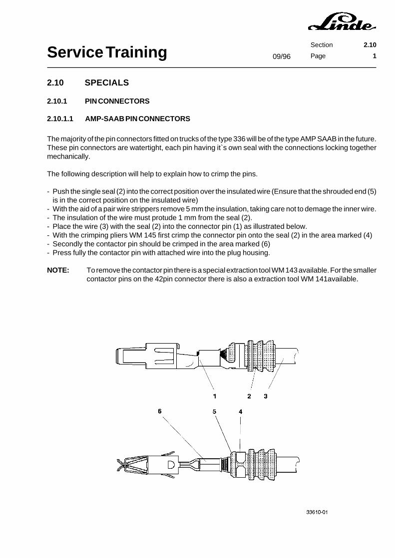
Service TrainingSection 2.10
Page 1
2.10 SPECIALS
2.10.1 PIN CONNECTORS
2.10.1.1 AMP-SAAB PIN CONNECTORS
The majority of the pin connectors fitted on trucks of the type 336 will be of the type AMP SAAB in the future.These pin connectors are watertight, each pin having it`s own seal with the connections locking togethermechanically.
The following description will help to explain how to crimp the pins.
- Push the single seal (2) into the correct position over the insulated wire (Ensure that the shrouded end (5)is in the correct position on the insulated wire)
- With the aid of a pair wire strippers remove 5 mm the insulation, taking care not to demage the inner wire.- The insulation of the wire must protude 1 mm from the seal (2).- Place the wire (3) with the seal (2) into the connector pin (1) as illustrated below.- With the crimping pliers WM 145 first crimp the connector pin onto the seal (2) in the area marked (4)- Secondly the contactor pin should be crimped in the area marked (6)- Press fully the contactor pin with attached wire into the plug housing.
NOTE: To remove the contactor pin there is a special extraction tool WM 143 available. For the smallercontactor pins on the 42pin connector there is also a extraction tool WM 141available.
09/96

Service TrainingSection 2.10
Page 2


336 804 2401.1295
LINDE AGWerksgruppe Flurförderzeuge und Hydraulik63701 AschaffenburgPostfach 10 01 36Telefon (0 60 21) 99-0Telefax (0 60 21) 99-15 70��������������������� ������������� ��������������� �����