lincolns mig-mag welding guide
DESCRIPTION
Lincolns MIG-MAG welding guideTRANSCRIPT
MIG/MAG Welding Guide
For Gas Metal Arc Welding (GMAW)
LINCOLNELECTRIC
®

This booklet contains basic guidelines onthe Gas Metal Arc Process.
The basic information is from “Recommended Practices forGas Metal Arc Welding”, AWS C5.6-89. It has beenedited and is reprinted through the courtesy of the
American Welding Society.
Mild Steel procedures were developed byThe Lincoln Electric Company.
Aluminum procedures are fromTHE ALUMINUM ASSOCIATION
Stainless Steel procedures are primarily fromJOINING OF STAINLESS STEEL
published byAmerican Society for Metals.
Welding Aluminum:Theory and Practice
The Aluminum Association
This book has been prepared by H.L. Saunders, Consultant, Alcan (Retired), with information and assistance from the Aluminum Association and from member companies represented on the Technical Advisory Panel on Welding and Joining.
Mr. Saunders (BASc, Mechanical Engineering, University of British Columbia) has 36 years of experience in the aluminum welding industry. He has been active in AWS, CSA, WIC and undertaken special studies for the National Research Council and the Welding Research Council. He was a former member and Chairman of the Aluminum Association’s Technical Committee on Welding and Joining.
Technical Advisory Panel on Welding and Joining:
B. Alshuller, Alcan (Chairman)P. Pollak, Aluminum Association (Secretary)P.B. Dickerson, Consultant, Alcoa (Retired)F. Armao, AlcoaEric R. Pickering, Reynolds Metals
Use of the InformationAny data and suggestions contained in this publication were compiled and/or developed by theAluminum Association, Inc. In view of the variety of conditions and methods of use to whichsuch data and suggestions may be applied, the Aluminum Association and its member companies assume no responsibility or liability for the use of information contained herein.Neither the Aluminum Association nor any of its member companies give any warranties,express or implied, in respect to this information.
Third Edition • November 1997
Copyright © 1991 by The Aluminum Association, Inc.
Library of Congress Catalog Card Number: 89-80539
Incorporated
ii
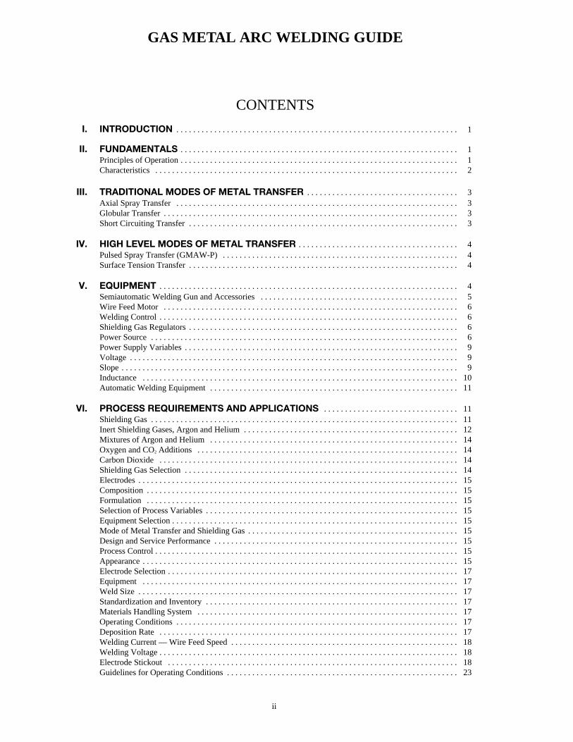
GAS METAL ARC WELDING GUIDE
CONTENTS
I. INTRODUCTION . . . . . . . . . . . . . . . . . . . . . . . . . . . . . . . . . . . . . . . . . . . . . . . . . . . . . . . . . . . . . . . . . . . 1
II. FUNDAMENTALS . . . . . . . . . . . . . . . . . . . . . . . . . . . . . . . . . . . . . . . . . . . . . . . . . . . . . . . . . . . . . . . . . . 1Principles of Operation . . . . . . . . . . . . . . . . . . . . . . . . . . . . . . . . . . . . . . . . . . . . . . . . . . . . . . . . . . . . . . . . . . 1Characteristics . . . . . . . . . . . . . . . . . . . . . . . . . . . . . . . . . . . . . . . . . . . . . . . . . . . . . . . . . . . . . . . . . . . . . . . . 2
III. TRADITIONAL MODES OF METAL TRANSFER . . . . . . . . . . . . . . . . . . . . . . . . . . . . . . . . . . . . 3Axial Spray Transfer . . . . . . . . . . . . . . . . . . . . . . . . . . . . . . . . . . . . . . . . . . . . . . . . . . . . . . . . . . . . . . . . . . . 3Globular Transfer . . . . . . . . . . . . . . . . . . . . . . . . . . . . . . . . . . . . . . . . . . . . . . . . . . . . . . . . . . . . . . . . . . . . . . 3Short Circuiting Transfer . . . . . . . . . . . . . . . . . . . . . . . . . . . . . . . . . . . . . . . . . . . . . . . . . . . . . . . . . . . . . . . . 3
IV. HIGH LEVEL MODES OF METAL TRANSFER . . . . . . . . . . . . . . . . . . . . . . . . . . . . . . . . . . . . . . 4Pulsed Spray Transfer (GMAW-P) . . . . . . . . . . . . . . . . . . . . . . . . . . . . . . . . . . . . . . . . . . . . . . . . . . . . . . . . 4Surface Tension Transfer . . . . . . . . . . . . . . . . . . . . . . . . . . . . . . . . . . . . . . . . . . . . . . . . . . . . . . . . . . . . . . . . 4
V. EQUIPMENT . . . . . . . . . . . . . . . . . . . . . . . . . . . . . . . . . . . . . . . . . . . . . . . . . . . . . . . . . . . . . . . . . . . . . . . 4Semiautomatic Welding Gun and Accessories . . . . . . . . . . . . . . . . . . . . . . . . . . . . . . . . . . . . . . . . . . . . . . . 5Wire Feed Motor . . . . . . . . . . . . . . . . . . . . . . . . . . . . . . . . . . . . . . . . . . . . . . . . . . . . . . . . . . . . . . . . . . . . . . 6Welding Control . . . . . . . . . . . . . . . . . . . . . . . . . . . . . . . . . . . . . . . . . . . . . . . . . . . . . . . . . . . . . . . . . . . . . . . 6Shielding Gas Regulators . . . . . . . . . . . . . . . . . . . . . . . . . . . . . . . . . . . . . . . . . . . . . . . . . . . . . . . . . . . . . . . . 6Power Source . . . . . . . . . . . . . . . . . . . . . . . . . . . . . . . . . . . . . . . . . . . . . . . . . . . . . . . . . . . . . . . . . . . . . . . . . 6Power Supply Variables . . . . . . . . . . . . . . . . . . . . . . . . . . . . . . . . . . . . . . . . . . . . . . . . . . . . . . . . . . . . . . . . . 9Voltage . . . . . . . . . . . . . . . . . . . . . . . . . . . . . . . . . . . . . . . . . . . . . . . . . . . . . . . . . . . . . . . . . . . . . . . . . . . . . . 9Slope . . . . . . . . . . . . . . . . . . . . . . . . . . . . . . . . . . . . . . . . . . . . . . . . . . . . . . . . . . . . . . . . . . . . . . . . . . . . . . . . 9Inductance . . . . . . . . . . . . . . . . . . . . . . . . . . . . . . . . . . . . . . . . . . . . . . . . . . . . . . . . . . . . . . . . . . . . . . . . . . . 10Automatic Welding Equipment . . . . . . . . . . . . . . . . . . . . . . . . . . . . . . . . . . . . . . . . . . . . . . . . . . . . . . . . . . . 11
VI. PROCESS REQUIREMENTS AND APPLICATIONS . . . . . . . . . . . . . . . . . . . . . . . . . . . . . . . . 11Shielding Gas . . . . . . . . . . . . . . . . . . . . . . . . . . . . . . . . . . . . . . . . . . . . . . . . . . . . . . . . . . . . . . . . . . . . . . . . . 11Inert Shielding Gases, Argon and Helium . . . . . . . . . . . . . . . . . . . . . . . . . . . . . . . . . . . . . . . . . . . . . . . . . . . 12Mixtures of Argon and Helium . . . . . . . . . . . . . . . . . . . . . . . . . . . . . . . . . . . . . . . . . . . . . . . . . . . . . . . . . . . 14Oxygen and CO2 Additions . . . . . . . . . . . . . . . . . . . . . . . . . . . . . . . . . . . . . . . . . . . . . . . . . . . . . . . . . . . . . . 14Carbon Dioxide . . . . . . . . . . . . . . . . . . . . . . . . . . . . . . . . . . . . . . . . . . . . . . . . . . . . . . . . . . . . . . . . . . . . . . . 14Shielding Gas Selection . . . . . . . . . . . . . . . . . . . . . . . . . . . . . . . . . . . . . . . . . . . . . . . . . . . . . . . . . . . . . . . . . 14Electrodes . . . . . . . . . . . . . . . . . . . . . . . . . . . . . . . . . . . . . . . . . . . . . . . . . . . . . . . . . . . . . . . . . . . . . . . . . . . . 15Composition . . . . . . . . . . . . . . . . . . . . . . . . . . . . . . . . . . . . . . . . . . . . . . . . . . . . . . . . . . . . . . . . . . . . . . . . . . 15Formulation . . . . . . . . . . . . . . . . . . . . . . . . . . . . . . . . . . . . . . . . . . . . . . . . . . . . . . . . . . . . . . . . . . . . . . . . . . 15Selection of Process Variables . . . . . . . . . . . . . . . . . . . . . . . . . . . . . . . . . . . . . . . . . . . . . . . . . . . . . . . . . . . . 15Equipment Selection . . . . . . . . . . . . . . . . . . . . . . . . . . . . . . . . . . . . . . . . . . . . . . . . . . . . . . . . . . . . . . . . . . . . 15Mode of Metal Transfer and Shielding Gas . . . . . . . . . . . . . . . . . . . . . . . . . . . . . . . . . . . . . . . . . . . . . . . . . . 15Design and Service Performance . . . . . . . . . . . . . . . . . . . . . . . . . . . . . . . . . . . . . . . . . . . . . . . . . . . . . . . . . . 15Process Control . . . . . . . . . . . . . . . . . . . . . . . . . . . . . . . . . . . . . . . . . . . . . . . . . . . . . . . . . . . . . . . . . . . . . . . . 15Appearance . . . . . . . . . . . . . . . . . . . . . . . . . . . . . . . . . . . . . . . . . . . . . . . . . . . . . . . . . . . . . . . . . . . . . . . . . . . 15Electrode Selection . . . . . . . . . . . . . . . . . . . . . . . . . . . . . . . . . . . . . . . . . . . . . . . . . . . . . . . . . . . . . . . . . . . . . 17Equipment . . . . . . . . . . . . . . . . . . . . . . . . . . . . . . . . . . . . . . . . . . . . . . . . . . . . . . . . . . . . . . . . . . . . . . . . . . . 17Weld Size . . . . . . . . . . . . . . . . . . . . . . . . . . . . . . . . . . . . . . . . . . . . . . . . . . . . . . . . . . . . . . . . . . . . . . . . . . . . 17Standardization and Inventory . . . . . . . . . . . . . . . . . . . . . . . . . . . . . . . . . . . . . . . . . . . . . . . . . . . . . . . . . . . . 17Materials Handling System . . . . . . . . . . . . . . . . . . . . . . . . . . . . . . . . . . . . . . . . . . . . . . . . . . . . . . . . . . . . . . 17Operating Conditions . . . . . . . . . . . . . . . . . . . . . . . . . . . . . . . . . . . . . . . . . . . . . . . . . . . . . . . . . . . . . . . . . . . 17Deposition Rate . . . . . . . . . . . . . . . . . . . . . . . . . . . . . . . . . . . . . . . . . . . . . . . . . . . . . . . . . . . . . . . . . . . . . . . 17Welding Current — Wire Feed Speed . . . . . . . . . . . . . . . . . . . . . . . . . . . . . . . . . . . . . . . . . . . . . . . . . . . . . . 18Welding Voltage . . . . . . . . . . . . . . . . . . . . . . . . . . . . . . . . . . . . . . . . . . . . . . . . . . . . . . . . . . . . . . . . . . . . . . . 18Electrode Stickout . . . . . . . . . . . . . . . . . . . . . . . . . . . . . . . . . . . . . . . . . . . . . . . . . . . . . . . . . . . . . . . . . . . . . 18Guidelines for Operating Conditions . . . . . . . . . . . . . . . . . . . . . . . . . . . . . . . . . . . . . . . . . . . . . . . . . . . . . . . 23

iii
VII. PROCEDURES FOR CARBON STEELS . . . . . . . . . . . . . . . . . . . . . . . . . . . . . . . . . . . . . . . . . . . . 24Welding Recommendations . . . . . . . . . . . . . . . . . . . . . . . . . . . . . . . . . . . . . . . . . . . . . . . . . . . . . . . . . . . . . . 24Wire Feed Speed . . . . . . . . . . . . . . . . . . . . . . . . . . . . . . . . . . . . . . . . . . . . . . . . . . . . . . . . . . . . . . . . . . . . . . 24Arc Voltage . . . . . . . . . . . . . . . . . . . . . . . . . . . . . . . . . . . . . . . . . . . . . . . . . . . . . . . . . . . . . . . . . . . . . . . . . . 24Shielding Gas and Gas Mixtures . . . . . . . . . . . . . . . . . . . . . . . . . . . . . . . . . . . . . . . . . . . . . . . . . . . . . . . . . . 24Carbon Dioxide . . . . . . . . . . . . . . . . . . . . . . . . . . . . . . . . . . . . . . . . . . . . . . . . . . . . . . . . . . . . . . . . . . . . . . . 24Argon . . . . . . . . . . . . . . . . . . . . . . . . . . . . . . . . . . . . . . . . . . . . . . . . . . . . . . . . . . . . . . . . . . . . . . . . . . . . . . . 24Argon and Carbon Dioxide . . . . . . . . . . . . . . . . . . . . . . . . . . . . . . . . . . . . . . . . . . . . . . . . . . . . . . . . . . . . . . 24Preheat & Interpass . . . . . . . . . . . . . . . . . . . . . . . . . . . . . . . . . . . . . . . . . . . . . . . . . . . . . . . . . . . . . . . . . . . . 25Horizontal Fillets or Flat Butt Welds by Short Circuiting . . . . . . . . . . . . . . . . . . . . . . . . . . . . . . . . . . . . . . . 26Vertical Down Fillets or Square Butt Welds by Short Circuiting . . . . . . . . . . . . . . . . . . . . . . . . . . . . . . . . . 26Vertical Up Welds by Short Circuiting . . . . . . . . . . . . . . . . . . . . . . . . . . . . . . . . . . . . . . . . . . . . . . . . . . . . . 27Flat and Horizontal Fillet Welds by Spray Transfer . . . . . . . . . . . . . . . . . . . . . . . . . . . . . . . . . . . . . . . . . . . 27Flat Butt Welds by Spray Transfer . . . . . . . . . . . . . . . . . . . . . . . . . . . . . . . . . . . . . . . . . . . . . . . . . . . . . . . . . 28Flat and Horizontal Fillet Welds by Pulsed Spray Transfer . . . . . . . . . . . . . . . . . . . . . . . . . . . . . . . . . . . . . . 28Vertical Up Fillet Welds by Pulsed Spray Transfer . . . . . . . . . . . . . . . . . . . . . . . . . . . . . . . . . . . . . . . . . . . . 29
VIII. WELDING STAINLESS STEEL . . . . . . . . . . . . . . . . . . . . . . . . . . . . . . . . . . . . . . . . . . . . . . . . . . . . . 29Spray Arc Transfer . . . . . . . . . . . . . . . . . . . . . . . . . . . . . . . . . . . . . . . . . . . . . . . . . . . . . . . . . . . . . . . . . . . . . 29Short Circuiting Transfer . . . . . . . . . . . . . . . . . . . . . . . . . . . . . . . . . . . . . . . . . . . . . . . . . . . . . . . . . . . . . . . . 29Procedure Range Blue Max MIG . . . . . . . . . . . . . . . . . . . . . . . . . . . . . . . . . . . . . . . . . . . . . . . . . . . . . . . . . . 30Flat Butt Welds by Spray Transfer . . . . . . . . . . . . . . . . . . . . . . . . . . . . . . . . . . . . . . . . . . . . . . . . . . . . . . . . . 30Flat and Horizontal Fillets and Flat Butts by Spray-Arc Transfer . . . . . . . . . . . . . . . . . . . . . . . . . . . . . . . . . 31Horizontal Flat Fillets or Flat Butt Welds by Short Circuiting . . . . . . . . . . . . . . . . . . . . . . . . . . . . . . . . . . . 32Pulsed-Arc Transfer . . . . . . . . . . . . . . . . . . . . . . . . . . . . . . . . . . . . . . . . . . . . . . . . . . . . . . . . . . . . . . . . . . . . 32Flat and Horizontal Fillets by Short Circuit Transfer . . . . . . . . . . . . . . . . . . . . . . . . . . . . . . . . . . . . . . . . . . . 33Vertical Up Fillets by Short Circuit Transfer . . . . . . . . . . . . . . . . . . . . . . . . . . . . . . . . . . . . . . . . . . . . . . . . . 34Flat and Horizontal Fillets by Pulsed Spray Transfer . . . . . . . . . . . . . . . . . . . . . . . . . . . . . . . . . . . . . . . . . . 34
IX. WELDING ALUMINUM . . . . . . . . . . . . . . . . . . . . . . . . . . . . . . . . . . . . . . . . . . . . . . . . . . . . . . . . . . . . . 35Horizontal Fillets with 5356 Filler Wire . . . . . . . . . . . . . . . . . . . . . . . . . . . . . . . . . . . . . . . . . . . . . . . . . . . . 35Horizontal Fillets with 4043 Filler Wire . . . . . . . . . . . . . . . . . . . . . . . . . . . . . . . . . . . . . . . . . . . . . . . . . . . . 36Flat Butt Welds with 5356 Filler Wire . . . . . . . . . . . . . . . . . . . . . . . . . . . . . . . . . . . . . . . . . . . . . . . . . . . . . . 36Flat Butt Welds with 4043 Filler Wire . . . . . . . . . . . . . . . . . . . . . . . . . . . . . . . . . . . . . . . . . . . . . . . . . . . . . . 37Flat and Horizontal Fillet Welds by Pulsed Spray Transfer . . . . . . . . . . . . . . . . . . . . . . . . . . . . . . . . . . . . . . 37
X. SAFE PRACTICES . . . . . . . . . . . . . . . . . . . . . . . . . . . . . . . . . . . . . . . . . . . . . . . . . . . . . . . . . . . . . . . . . 38Introduction . . . . . . . . . . . . . . . . . . . . . . . . . . . . . . . . . . . . . . . . . . . . . . . . . . . . . . . . . . . . . . . . . . . . . . . . . . 38Handling of Shielding Gas Cylinders & Regulators . . . . . . . . . . . . . . . . . . . . . . . . . . . . . . . . . . . . . . . . . . . 38Cylinder Use . . . . . . . . . . . . . . . . . . . . . . . . . . . . . . . . . . . . . . . . . . . . . . . . . . . . . . . . . . . . . . . . . . . . . . . . . . 38Gases . . . . . . . . . . . . . . . . . . . . . . . . . . . . . . . . . . . . . . . . . . . . . . . . . . . . . . . . . . . . . . . . . . . . . . . . . . . . . . . 38Ozone . . . . . . . . . . . . . . . . . . . . . . . . . . . . . . . . . . . . . . . . . . . . . . . . . . . . . . . . . . . . . . . . . . . . . . . . . . . . . . . 38Nitrogen Dioxide . . . . . . . . . . . . . . . . . . . . . . . . . . . . . . . . . . . . . . . . . . . . . . . . . . . . . . . . . . . . . . . . . . . . . . 38Carbon Monoxide . . . . . . . . . . . . . . . . . . . . . . . . . . . . . . . . . . . . . . . . . . . . . . . . . . . . . . . . . . . . . . . . . . . . . . 38Metal Fumes . . . . . . . . . . . . . . . . . . . . . . . . . . . . . . . . . . . . . . . . . . . . . . . . . . . . . . . . . . . . . . . . . . . . . . . . . . 38Radiant Energy . . . . . . . . . . . . . . . . . . . . . . . . . . . . . . . . . . . . . . . . . . . . . . . . . . . . . . . . . . . . . . . . . . . . . . . . 39Noise — Hearing Protection . . . . . . . . . . . . . . . . . . . . . . . . . . . . . . . . . . . . . . . . . . . . . . . . . . . . . . . . . . . . . 39Arc Welding Safety Precautions . . . . . . . . . . . . . . . . . . . . . . . . . . . . . . . . . . . . . . . . . . . . . . . . . . . . . . . . 40-42
XI. PRODUCT REFERENCES . . . . . . . . . . . . . . . . . . . . . . . . . . . . . . . . . . . . . . . . . . . . . . . . . . . . . . . . . 39
The serviceability of a product or structure utilizing this type of information is and must be the sole responsibility of thebuilder/user. Many variables beyond the control of The Lincoln Electric Company affect the results obtained in applyingthis type of information. These variables include, but are not limited to, welding procedure, plate chemistry and temperature,weldment design, fabrication methods and service requirements.
1
Note: The U.S. customary units are primary in this publication.However, the approximate equivalent SI values are listed intext and tables to familiarize the reader with the SI system ofmetric units.
I. INTRODUCTION
This publication describes the basic concepts of the gas metalarc welding (GMAW) process. It will provide the reader witha fundamental understanding of the process and its variations.This knowledge, combined with basic information about otherwelding processes, will be helpful in selecting the best weldingprocess for the materials to be joined. In addition, the readerwill find specific technical data which will be a guide inestablishing optimum operation of this process.
The GMAW process was developed and made commerciallyavailable in 1948, although the basic concept was actually in-troduced in the 1920’s. In its early commercial applications,the process was used to weld aluminum with an inert shieldinggas, giving rise to the term “MIG” (metal inert gas) which isstill commonly used when referring to the process.
Variations have been added to the process, among which wasthe use of active shielding gases, particularly CO2, for weldingcertain ferrous metals. This eventually led to the formallyaccepted AWS term of gas metal arc welding (GMAW) for theprocess. Further developments included the short circuitingmode of metal transfer (GMAW-S), a lower heat energy var-iation of the process that permits welding out-of-position andalso on materials of sheet metal thicknesses; and a method ofcontrolled pulsating current (GMAW-P) to provide a uniformspray droplet metal transfer from the electrode at a lower averagecurrent levels.
The GMAW process uses either semiautomatic or automaticequipment and is principally applied in high production weld-ing. Most metals can be welded with this process and may bewelded in all positions with the lower energy variations of theprocess. GMAW is an economical process that requires littleor no cleaning of the weld deposit. Warpage is reduced andmetal finishing is minimal compared to stick welding.
II. FUNDAMENTALS
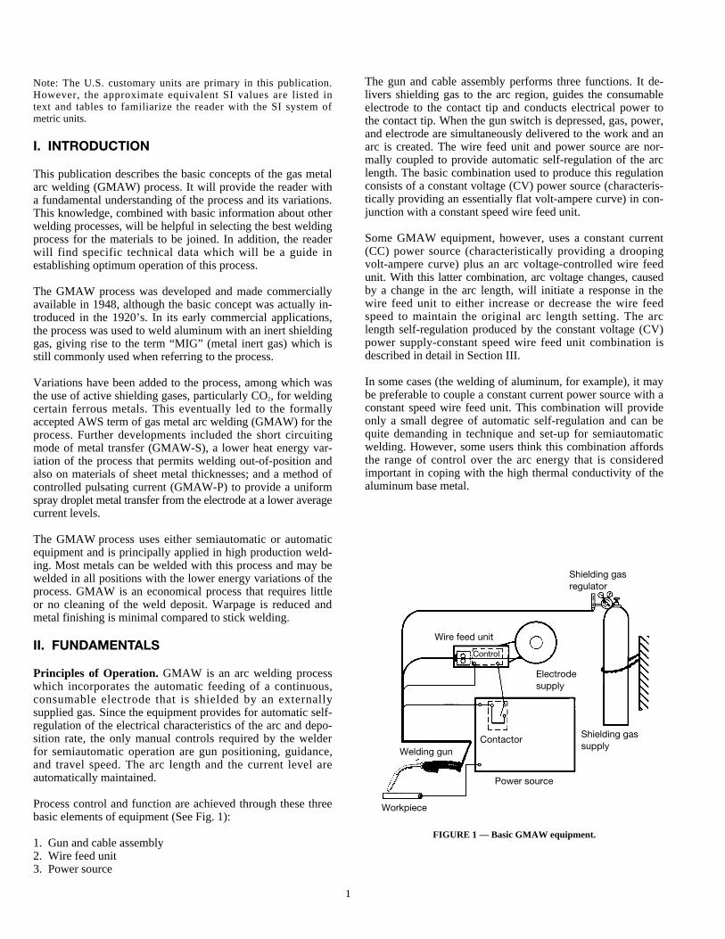
Principles of Operation. GMAW is an arc welding processwhich incorporates the automatic feeding of a continuous,consumable electrode that is shielded by an externallysupplied gas. Since the equipment provides for automatic self-regulation of the electrical characteristics of the arc and depo-sition rate, the only manual controls required by the welderfor semiautomatic operation are gun positioning, guidance,and travel speed. The arc length and the current level areautomatically maintained.
Process control and function are achieved through these threebasic elements of equipment (See Fig. 1):
1. Gun and cable assembly2. Wire feed unit3. Power source
The gun and cable assembly performs three functions. It de-livers shielding gas to the arc region, guides the consumableelectrode to the contact tip and conducts electrical power tothe contact tip. When the gun switch is depressed, gas, power,and electrode are simultaneously delivered to the work and anarc is created. The wire feed unit and power source are nor-mally coupled to provide automatic self-regulation of the arclength. The basic combination used to produce this regulationconsists of a constant voltage (CV) power source (characteris-tically providing an essentially flat volt-ampere curve) in con-junction with a constant speed wire feed unit.
Some GMAW equipment, however, uses a constant current(CC) power source (characteristically providing a droopingvolt-ampere curve) plus an arc voltage-controlled wire feedunit. With this latter combination, arc voltage changes, causedby a change in the arc length, will initiate a response in thewire feed unit to either increase or decrease the wire feedspeed to maintain the original arc length setting. The arclength self-regulation produced by the constant voltage (CV)power supply-constant speed wire feed unit combination isdescribed in detail in Section III.
In some cases (the welding of aluminum, for example), it maybe preferable to couple a constant current power source with aconstant speed wire feed unit. This combination will provideonly a small degree of automatic self-regulation and can bequite demanding in technique and set-up for semiautomaticwelding. However, some users think this combination affordsthe range of control over the arc energy that is consideredimportant in coping with the high thermal conductivity of thealuminum base metal.
FIGURE 1 — Basic GMAW equipment.
Shielding gasregulator
Wire feed unit
Control
Electrodesupply
Contactor
Workpiece
Power source
Shielding gassupply
Welding gun
2
Characteristics. The characteristics of GMAW are bestdescribed by the five basic modes of transfer which may occurwith the process. Three traditional modes of transfer are shortcircuiting, globular and axial spray. With more recent devel-opments in power source technology, two higher level transfermodes, pulsed spray and Surface Tension Transfer™ (STT®)have been developed. Even though these power sources aremore expensive, the advantages enable users to easily justifythe additional cost on many applications.
Axial spray and globular transfer are associated basically withrelatively high arc energy. With the occasional exception ofthe spray mode in very small diameter electrodes, both axialspray and globular transfer are normally limited to the flat andhorizontal welding positions with material thicknesses of notless than 1/8 in. (3.2 mm). Pulsed spray transfer, in which theaverage energy level is reduced, is another exception (seeGMAW-P). STT and traditional short circuiting transfer arerelatively low energy processes generally limited to metalthicknesses not more than 1/8 in. (3.2mm), but is used in allwelding positions.
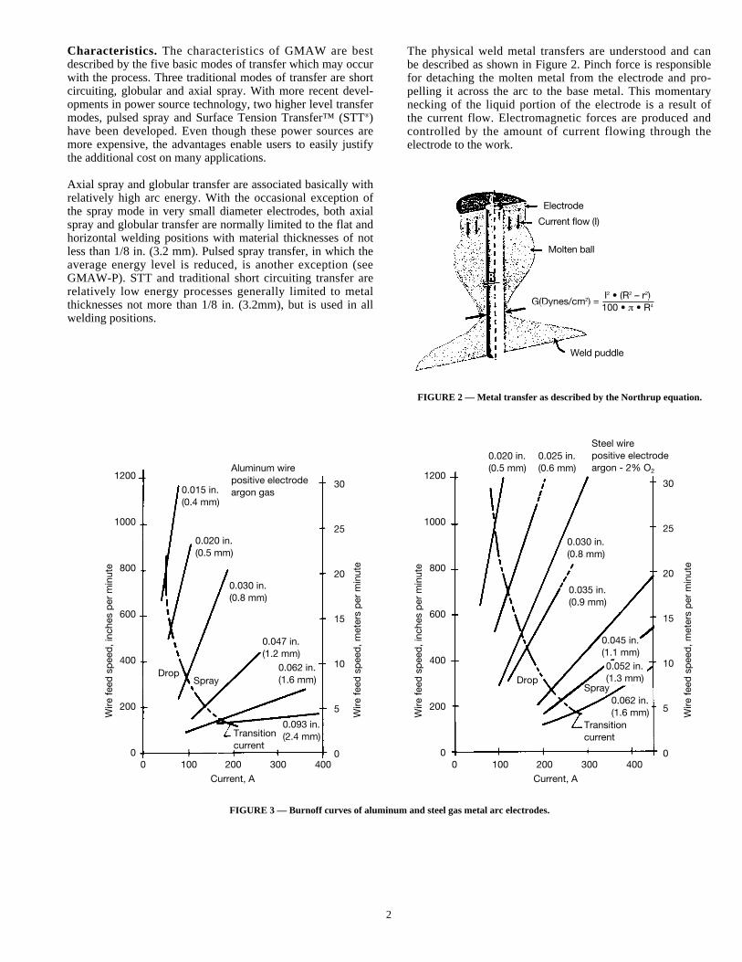
The physical weld metal transfers are understood and canbe described as shown in Figure 2. Pinch force is responsiblefor detaching the molten metal from the electrode and pro-pelling it across the arc to the base metal. This momentarynecking of the liquid portion of the electrode is a result ofthe current flow. Electromagnetic forces are produced andcontrolled by the amount of current flowing through theelectrode to the work.
FIGURE 2 — Metal transfer as described by the Northrup equation.
FIGURE 3 — Burnoff curves of aluminum and steel gas metal arc electrodes.
Current, A
Aluminum wirepositive electrodeargon gas
Steel wirepositive electrodeargon - 2% O2
0.020 in.(0.5 mm)
0.025 in.(0.6 mm)
0.030 in.(0.8 mm)
0.035 in.(0.9 mm)
0.045 in.(1.1 mm)0.052 in.(1.3 mm)
0.062 in.(1.6 mm)
TransitioncurrentTransition
current
0.093 in.(2.4 mm)
0.062 in.(1.6 mm)
0.047 in.(1.2 mm)
0.030 in.(0.8 mm)
0.020 in.(0.5 mm)
0.015 in.(0.4 mm)
DropSpray
Spray
0 100 200 300 400
Wire
feed
sp
eed
, inc
hes
per
min
ute
Wire
feed
sp
eed
, met
ers
per
min
ute
0 100 200 300 400
Current, A
1200
1000
800
600
400
200
0
30
25
20
15
10
5
0
Wire
feed
sp
eed
, inc
hes
per
min
ute
Wire
feed
sp
eed
, met
ers
per
min
ute
1200
1000
800
600
400
200
0
30
25
20
15
10
5
0
Drop
Electrode
Current flow (I)
G(Dynes/cm2) = I2 • (R2 – r2)G(Dynes/cm2) = 100 • ¹ • R4
G(Dynes/cm2) = 100 • ¹ • R4
Weld puddle
Molten ball
3
III. TRADITIONAL MODES OF METAL TRANSFER
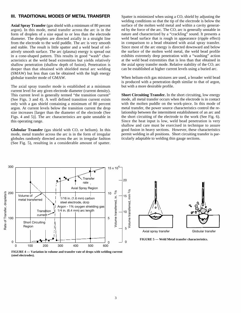
Axial Spray Transfer (gas shield with a minimum of 80 percentargon). In this mode, metal transfer across the arc is in theform of droplets of a size equal to or less than the electrodediameter. The droplets are directed axially in a straight linefrom the electrode to the weld puddle. The arc is very smoothand stable. The result is little spatter and a weld bead of rel-atively smooth surface. The arc (plasma) energy is spread outin a cone-shaped pattern. This results in good “wash” char-acteristics at the weld bead extremities but yields relativelyshallow penetration (shallow depth of fusion). Penetration isdeeper than that obtained with shielded metal arc welding(SMAW) but less than can be obtained with the high energyglobular transfer mode of GMAW.
The axial spray transfer mode is established at a minimumcurrent level for any given electrode diameter (current density).This current level is generally termed “the transition current”(See Figs. 3 and 4). A well defined transition current existsonly with a gas shield containing a minimum of 80 percentargon. At current levels below the transition current the dropsize increases [larger than the diameter of the electrode (SeeFigs. 4 and 5)]. The arc characteristics are quite unstable inthis operating range.
Globular Transfer (gas shield with CO2 or helium). In thismode, metal transfer across the arc is in the form of irregularglobules randomly directed across the arc in irregular fashion(See Fig. 5), resulting in a considerable amount of spatter.
Spatter is minimized when using a CO2 shield by adjusting thewelding conditions so that the tip of the electrode is below thesurface of the molten weld metal and within a cavity generat-ed by the force of the arc. The CO2 arc is generally unstable innature and characterized by a “crackling” sound. It presents aweld bead surface that is rough in appearance (ripple effect)in comparison to a bead obtained with axial spray transfer.Since most of the arc energy is directed downward and belowthe surface of the molten weld metal, the weld bead profileexhibits extremely deep penetration with a “washing” actionat the weld bead extremities that is less than that obtained inthe axial spray transfer mode. Relative stability of the CO2 arccan be established at higher current levels using a buried arc.
When helium-rich gas mixtures are used, a broader weld beadis produced with a penetration depth similar to that of argon,but with a more desirable profile.
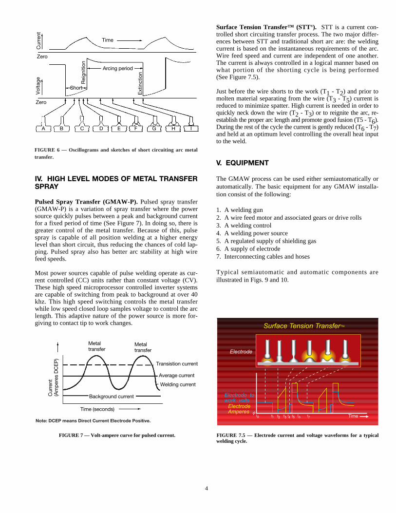
Short Circuiting Transfer. In the short circuiting, low energymode, all metal transfer occurs when the electrode is in contactwith the molten puddle on the work-piece. In this mode ofmetal transfer, the power source characteristics control the re-lationship between the intermittent establishment of an arc andthe short circuiting of the electrode to the work (See Fig. 6).Since the heat input is low, weld bead penetration is veryshallow and care must be exercised in technique to assuregood fusion in heavy sections. However, these characteristicspermit welding in all positions. Short circuiting transfer is par-ticularly adaptable to welding thin gauge sections.
FIGURE 4 — Variation in volume and transfer rate of drops with welding current(steel electrodes).
FIGURE 5 — Weld Metal transfer characteristics.
Volume ofmetal transferred
Transferrate
Axial spray transfer Globular transfer
Transitioncurrent
1/16 in. (1.6 mm) carbonsteel electrode, dcrp
Argon - 1% oxygen shielding gas1/4 in. (6.4 mm) arc length
0 100 200 300 400 500 600
Rat
e of
Tra
nsfe
r, d
rop
lets
/s
300
200
100
0
20
15
10
5
0
15 x 104
10
5
0
Short CircuitingRegion
Axial Spray Region
Vol
ume
tran
sfer
red
, in.
3/s
Vol
ume
tran
sfer
red
, mm
3/s
4
IV. HIGH LEVEL MODES OF METAL TRANSFERSPRAY
Pulsed Spray Transfer (GMAW-P). Pulsed spray transfer(GMAW-P) is a variation of spray transfer where the powersource quickly pulses between a peak and background currentfor a fixed period of time (See Figure 7). In doing so, there isgreater control of the metal transfer. Because of this, pulsespray is capable of all position welding at a higher energylevel than short circuit, thus reducing the chances of cold lap-ping. Pulsed spray also has better arc stability at high wirefeed speeds.
Most power sources capable of pulse welding operate as cur-rent controlled (CC) units rather than constant voltage (CV).These high speed microprocessor controlled inverter systemsare capable of switching from peak to background at over 40khz. This high speed switching controls the metal transferwhile low speed closed loop samples voltage to control the arclength. This adaptive nature of the power source is more for-giving to contact tip to work changes.
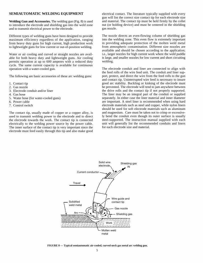
Surface Tension Transfer™ (STT®). STT is a current con-trolled short circuiting transfer process. The two major differ-ences between STT and traditional short arc are: the weldingcurrent is based on the instantaneous requirements of the arc.Wire feed speed and current are independent of one another.The current is always controlled in a logical manner based onwhat portion of the shorting cycle is being performed(See Figure 7.5).
Just before the wire shorts to the work (T1 - T2) and prior tomolten material separating from the wire (T3 - T5) current isreduced to minimize spatter. High current is needed in order toquickly neck down the wire (T2 - T3) or to reignite the arc, re-establish the proper arc length and promote good fusion (T5 - T6).During the rest of the cycle the current is gently reduced (T6 - T7)and held at an optimum level controlling the overall heat inputto the weld.
V. EQUIPMENT
The GMAW process can be used either semiautomatically orautomatically. The basic equipment for any GMAW installa-tion consist of the following:
1. A welding gun2. A wire feed motor and associated gears or drive rolls3. A welding control4. A welding power source5. A regulated supply of shielding gas6. A supply of electrode7. Interconnecting cables and hoses
Typical semiautomatic and automatic components areillustrated in Figs. 9 and 10.
FIGURE 7 — Volt-ampere curve for pulsed current. FIGURE 7.5 — Electrode current and voltage waveforms for a typicalwelding cycle.
Note: DCEP means Direct Current Electrode Positive.
FIGURE 6 — Oscillograms and sketches of short circuiting arc metaltransfer.
Time
Zero
Short
Zero
A B C D E F G H I
Vol
tage Rei
gniti
on
Ext
inct
ion
Cur
rent
Arcing period
Time (seconds)
Metaltransfer
Metaltransfer
Transistion current
Average current
Welding current
Cur
rent
(Am
pere
s D
CE
P)
Background current
5
SEMIAUTOMATIC WELDING EQUIPMENT
Welding Gun and Accessories.The welding gun (Fig. 8) is usedto introduce the electrode and shielding gas into the weld zoneand to transmit electrical power to the electrode.
Different types of welding guns have been designed to providemaximum efficiency regardless of the application, rangingfrom heavy duty guns for high current, high production workto lightweight guns for low current or out-of-position welding.
Water or air cooling and curved or straight nozzles are avail-able for both heavy duty and lightweight guns. Air coolingpermits operation at up to 600 amperes with a reduced dutycycle. The same current capacity is available for continuousoperation with a water-cooled gun.
The following are basic accessories of these arc welding guns:
1. Contact tip2. Gas nozzle3. Electrode conduit and/or liner4. Gas hose5. Water hose (for water-cooled guns)6. Power cable7. Control switch
The contact tip, usually made of copper or a copper alloy, isused to transmit welding power to the electrode and to directthe electrode towards the work. The contact tip is connectedelectrically to the welding power source by the power cable.The inner surface of the contact tip is very important since theelectrode must feed easily through this tip and also make good
electrical contact. The literature typically supplied with everygun will list the correct size contact tip for each electrode sizeand material. The contact tip must be held firmly by the colletnut (or holding device) and must be centered in the shieldinggas nozzle.
The nozzle directs an even-flowing column of shielding gasinto the welding zone. This even flow is extremely importantin providing adequate protection of the molten weld metalfrom atmospheric contamination. Different size nozzles areavailable and should be chosen according to the application;i.e., larger nozzles for high current work where the weld puddleis large, and smaller nozzles for low current and short circuitingwelding.
The electrode conduit and liner are connected to align withthe feed rolls of the wire feed unit. The conduit and liner sup-port, protect, and direct the wire from the feed rolls to the gunand contact tip. Uninterrupted wire feed is necessary to insuregood arc stability. Buckling or kinking of the electrode mustbe prevented. The electrode will tend to jam anywhere betweenthe drive rolls and the contact tip if not properly supported.The liner may be an integral part of the conduit or suppliedseparately. In either case the liner material and inner diameterare important. A steel liner is recommended when using hardelectrode materials such as steel and copper, while nylon linersshould be used for soft electrode materials such as aluminumand magnesium. Care must be taken not to crimp or excessive-ly bend the conduit even though its outer surface is usuallysteel-supported. The instruction manual supplied with eachunit will generally list the recommended conduits and linersfor each electrode size and material.
FIGURE 8 — Typical semiautomatic air-cooled, curved-neck gas metal arc welding gun.
Travel
Solidifiedweld metal
Arc
Work
Molten weldmetal
Current conductor
Solid wireelectrode
Shielding gasIN
Wire guide andcontact tip
Gas nozzle
Shielding gas
6
The remaining accessories bring the shielding gas, coolingwater, and welding power to the gun. These hoses and cablesmay be connected directly to the source of these facilities orto the welding control. Trailing-gas shields are availableand may be required to protect the weld pool during high speedwelding.
The basic gun uses a wire feeder to push the electrode from aremote location through the conduit, a distance of typicallyabout 12 ft. (3.7 m). Several other designs are also available,including a unit with a small electrode feed mechanism builtinto the gun. This system will pull the electrode from a moredistant source where an additional drive may also be used topush the electrode into the longer conduit needed. Anothervariation is the “spool-on-gun” type in which the electrode feedmechanism and the electrode source are self-contained.
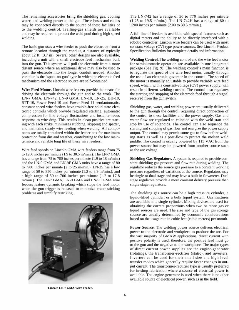
Wire Feed Motor. Lincoln wire feeders provide the means fordriving the electrode through the gun and to the work. TheLN-7 GMA, LN-742, LN-9 GMA, LN-10, LN-25, DH-10,STT-10, Power Feed 10 and Power Feed 11 semiautomatic,constant speed wire feeders have trouble-free solid state elec-tronic controls which provide regulated starting, automaticcompression for line voltage fluctuations and instanta-neousresponse to wire drag. This results in clean positive arc start-ing with each strike, minimizes stubbing, skipping and spatter,and maintains steady wire feeding when welding. All compo-nents are totally contained within the feeder box for maximumprotection from dirt and weather, contributing to the low main-tenance and reliable long life of these wire feeders.
Wire feed speeds on Lincoln GMA wire feeders range from 75to 1200 inches per minute (1.9 to 30.5 m/min.). The LN-7 GMAhas a range from 75 to 700 inches per minute (1.9 to 18 m/min.)and the LN-9 GMA and LN-9F GMA units have a range of 80to 980 inches per minute (2 to 25 m/min.). LN-25 has a lowrange of 50 to 350 inches per minute (1.2 to 8.9 m/min.), anda high range of 50 to 700 inches per minute (1.2 to 17.8m/min.). The LN-7 GMA, LN-9 GMA and LN-9F GMA wirefeeders feature dynamic breaking which stops the feed motorwhen the gun trigger is released to minimize crater stickingproblems and simplify restriking.
The LN-742 has a range of 50 to 770 inches per minute(1.25 to 19.5 m/min.). The LN-742H has a range of 80 to1200 inches per minute (2.00 to 30.5 m/min.).
A full line of feeders is available with special features such asdigital meters and the ability to be directly interfaced with arobotic controller. Lincoln wire feeders can be used with mostconstant voltage (CV) type power sources. See Lincoln ProductSpecification Bulletins for complete details and information.
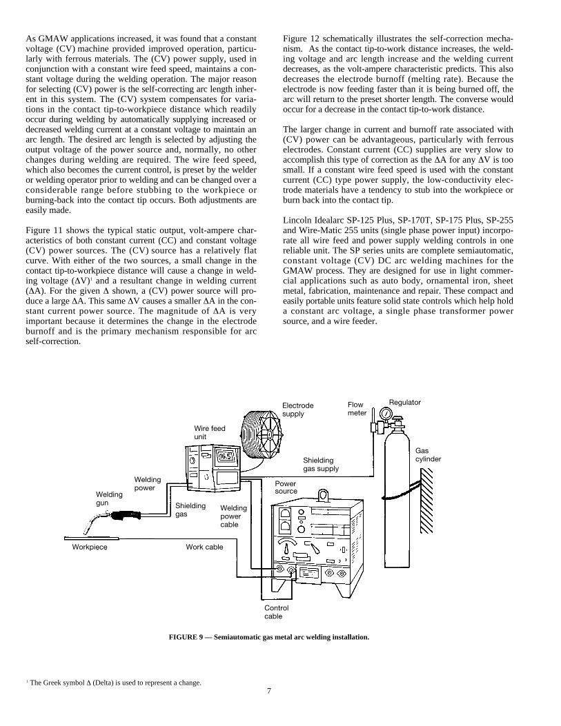
Welding Control. The welding control and the wire feed motorfor semiautomatic operation are available in one integratedpackage (See Fig. 9). The welding control’s main function isto regulate the speed of the wire feed motor, usually throughthe use of an electronic governor in the control. The speed ofthe motor is manually adjustable to provide variable wire feedspeed, which, with a constant-voltage (CV) power supply, willresult in different welding current. The control also regulatesthe starting and stopping of the electrode feed through a signalreceived from the gun switch.
Shielding gas, water, and welding power are usually deliveredto the gun through the control, requiring direct connection ofthe control to these facilities and the power supply. Gas andwater flow are regulated to coincide with the weld start andstop by use of solenoids. The control can also sequence thestarting and stopping of gas flow and energize the power supplyoutput. The control may permit some gas to flow before weld-ing starts as well as a post-flow to protect the molten weldpuddle. The control is usually powered by 115 VAC from thepower source but may be powered from another source suchas the arc voltage.
Shielding Gas Regulators.A system is required to provide con-stant shielding gas pressure and flow rate during welding. Theregulator reduces the source gas pressure to a constant workingpressure regardless of variations at the source. Regulators maybe single or dual stage and may have a built-in flowmeter. Dualstage regulators provide a more constant delivery pressure thansingle stage regulators.
The shielding gas source can be a high pressure cylinder, aliquid-filled cylinder, or a bulk liquid system. Gas mixturesare available in a single cylinder. Mixing devices are used forobtaining the correct proportions when two or more gas orliquid sources are used. The size and type of the gas storagesource are usually determined by economic considerationsbased on the usage rate in cubic feet (cubic meters) per month.
Power Source.The welding power source delivers electricalpower to the electrode and workpiece to produce the arc. Forthe vast majority of GMAW applications, direct current withpositive polarity is used; therefore, the positive lead must goto the gun and the negative to the workpiece. The major typesof direct current power supplies are the engine-generator(rotating), the transformer-rectifier (static), and inverters.Inverters can be used for their small size and high leveltransfer modes which generally require faster changes in out-put current. The transformer-rectifier type is usually preferredfor in-shop fabrication where a source of electrical power isavailable. The engine-generator is used when there is no otheravailable source of electrical power, such as in the field.
Lincoln LN-7 GMA Wire Feeder.
7
As GMAW applications increased, it was found that a constantvoltage (CV) machine provided improved operation, particu-larly with ferrous materials. The (CV) power supply, used inconjunction with a constant wire feed speed, maintains a con-stant voltage during the welding operation. The major reasonfor selecting (CV) power is the self-correcting arc length inher-ent in this system. The (CV) system compensates for varia-tions in the contact tip-to-workpiece distance which readilyoccur during welding by automatically supplying increased ordecreased welding current at a constant voltage to maintain anarc length. The desired arc length is selected by adjusting theoutput voltage of the power source and, normally, no otherchanges during welding are required. The wire feed speed,which also becomes the current control, is preset by the welderor welding operator prior to welding and can be changed over aconsiderable range before stubbing to the workpiece orburning-back into the contact tip occurs. Both adjustments areeasily made.
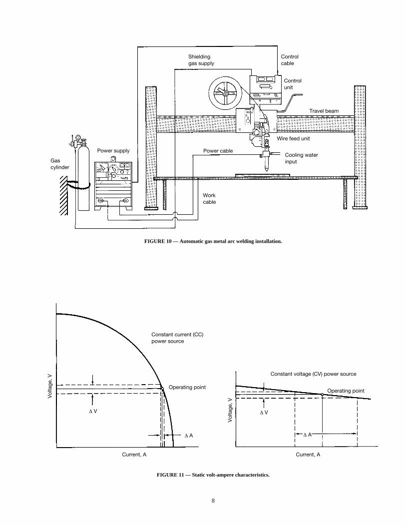
Figure 11 shows the typical static output, volt-ampere char-acteristics of both constant current (CC) and constant voltage(CV) power sources. The (CV) source has a relatively flatcurve. With either of the two sources, a small change in thecontact tip-to-workpiece distance will cause a change in weld-ing voltage (ÆV)1 and a resultant change in welding current(ÆA). For the given Æ shown, a (CV) power source will pro-duce a large ÆA. This same ÆV causes a smaller ÆA in the con-stant current power source. The magnitude of ÆA is veryimportant because it determines the change in the electrodeburnoff and is the primary mechanism responsible for arcself-correction.
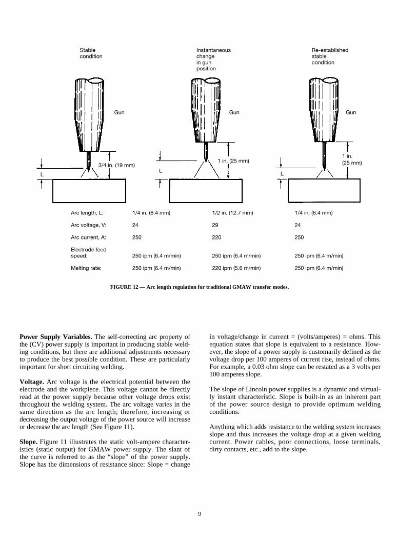
Figure 12 schematically illustrates the self-correction mecha-nism. As the contact tip-to-work distance increases, the weld-ing voltage and arc length increase and the welding currentdecreases, as the volt-ampere characteristic predicts. This alsodecreases the electrode burnoff (melting rate). Because theelectrode is now feeding faster than it is being burned off, thearc will return to the preset shorter length. The converse wouldoccur for a decrease in the contact tip-to-work distance.
The larger change in current and burnoff rate associated with(CV) power can be advantageous, particularly with ferrouselectrodes. Constant current (CC) supplies are very slow toaccomplish this type of correction as the ÆA for any ÆV is toosmall. If a constant wire feed speed is used with the constantcurrent (CC) type power supply, the low-conductivity elec-trode materials have a tendency to stub into the workpiece orburn back into the contact tip.
Lincoln Idealarc SP-125 Plus, SP-170T, SP-175 Plus, SP-255and Wire-Matic 255 units (single phase power input) incorpo-rate all wire feed and power supply welding controls in onereliable unit. The SP series units are complete semiautomatic,constant voltage (CV) DC arc welding machines for theGMAW process. They aredesigned for use in light commer-cial applications such as auto body, ornamental iron, sheetmetal, fabrication, maintenance and repair. These compact andeasily portable units feature solidstate controls which help holda constant arc voltage, a single phase transformer powersource, and a wire feeder.
FIGURE 9 — Semiautomatic gas metal arc welding installation.
1 The Greek symbol Æ (Delta) is used to represent a change.
Wire feedunit
Shieldinggas
Weldingpower
Weldinggun
Workpiece Work cable
Controlcable
Electrodesupply
Shieldinggas supply
Flowmeter
Regulator
Gascylinder
Powersource
Weldingpowercable
8
FIGURE 10 — Automatic gas metal arc welding installation.
FIGURE 11 — Static volt-ampere characteristics.
Shieldinggas supply
Controlcable
Controlunit
Travel beam
Wire feed unit
Cooling waterinput
Power cable
Workcable
Power supply
Gascylinder
Constant current (CC)power source
Constant voltage (CV) power source
Operating pointOperating point
Current, A Current, A
Æ V Æ V
Æ A Æ A
Vol
tage
, V
Vol
tage
, V
9
FIGURE 12 — Arc length regulation for traditional GMAW transfer modes.
Power Supply Variables.The self-correcting arc property ofthe (CV) power supply is important in producing stable weld-ing conditions, but there are additional adjustments necessaryto produce the best possible condition. These are particularlyimportant for short circuiting welding.
Voltage. Arc voltage is the electrical potential between theelectrode and the workpiece. This voltage cannot be directlyread at the power supply because other voltage drops existthroughout the welding system. The arc voltage varies in thesame direction as the arc length; therefore, increasing ordecreasing the output voltage of the power source will increaseor decrease the arc length (See Figure 11).
Slope.Figure 11 illustrates the static volt-ampere character-istics (static output) for GMAW power supply. The slant ofthe curve is referred to as the “slope” of the power supply.Slope has the dimensions of resistance since: Slope = change
in voltage/change in current = (volts/amperes) = ohms. Thisequation states that slope is equivalent to a resistance. How-ever, the slope of a power supply is customarily defined as thevoltage drop per 100 amperes of current rise, instead of ohms.For example, a 0.03 ohm slope can be restated as a 3 volts per100 amperes slope.
The slope of Lincoln power supplies is a dynamic and virtual-ly instant characteristic. Slope is built-in as an inherent partof the power source design to provide optimum weldingconditions.
Anything which adds resistance to the welding system increasesslope and thus increases the voltage drop at a given weldingcurrent. Power cables, poor connections, loose terminals,dirty contacts, etc., add to the slope.
Stable Instantaneous Re-establishedcondition change stable
in gun conditionposition
Arc length, L: 1/4 in. (6.4 mm) 1/2 in. (12.7 mm) 1/4 in. (6.4 mm)
Arc voltage, V: 24 29 24
Arc current, A: 250 220 250
Electrode feedspeed: 250 ipm (6.4 m/min) 250 ipm (6.4 m/min) 250 ipm (6.4 m/min)
Melting rate: 250 ipm (6.4 m/min) 220 ipm (5.6 m/min) 250 ipm (6.4 m/min)
Gun
LL L
Gun Gun
3/4 in. (19 mm)1 in. (25 mm)
1 in.(25 mm)
10
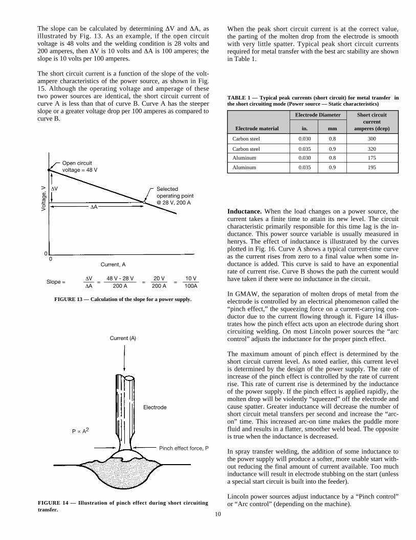
The slope can be calculated by determining ÆV and ÆA, asillustrated by Fig. 13. As an example, if the open circuitvoltage is 48 volts and the welding condition is 28 volts and200 amperes, then ÆV is 10 volts and ÆA is 100 amperes; theslope is 10 volts per 100 amperes.
The short circuit current is a function of the slope of the volt-ampere characteristics of the power source, as shown in Fig.15. Although the operating voltage and amperage of thesetwo power sources are identical, the short circuit current ofcurve A is less than that of curve B. Curve A has the steeperslope or a greater voltage drop per 100 amperes as compared tocurve B.
When the peak short circuit current is at the correct value,the parting of the molten drop from the electrode is smoothwith very little spatter. Typical peak short circuit currentsrequired for metal transfer with the best arc stability are shownin Table 1.
Inductance. When the load changes on a power source, thecurrent takes a finite time to attain its new level. The circuitcharacteristic primarily responsible for this time lag is the in-ductance. This power source variable is usually measured inhenrys. The effect of inductance is illustrated by the curvesplotted in Fig. 16. Curve A shows a typical current-time curveas the current rises from zero to a final value when some in-ductance is added. This curve is said to have an exponentialrate of current rise. Curve B shows the path the current wouldhave taken if there were no inductance in the circuit.
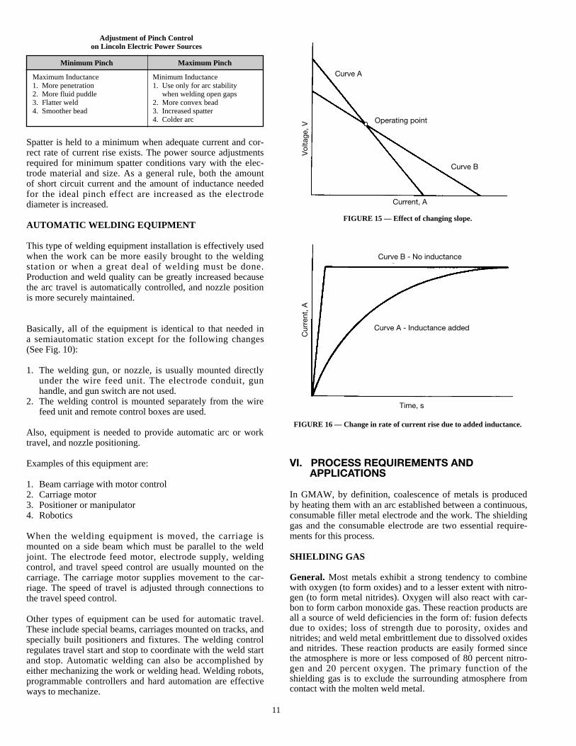
In GMAW, the separation of molten drops of metal from theelectrode is controlled by an electrical phenomenon called the“pinch effect,” the squeezing force on a current-carrying con-ductor due to the current flowing through it. Figure 14 illus-trates how the pinch effect acts upon an electrode during shortcircuiting welding. On most Lincoln power sources the “arccontrol” adjusts the inductance for the proper pinch effect.
The maximum amount of pinch effect is determined by theshort circuit current level. As noted earlier, this current levelis determined by the design of the power supply. The rate ofincrease of the pinch effect is controlled by the rate of currentrise. This rate of current rise is determined by the inductanceof the power supply. If the pinch effect is applied rapidly, themolten drop will be violently “squeezed” off the electrode andcause spatter. Greater inductance will decrease the number ofshort circuit metal transfers per second and increase the “arc-on” time. This increased arc-on time makes the puddle morefluid and results in a flatter, smoother weld bead. The oppositeis true when the inductance is decreased.
In spray transfer welding, the addition of some inductance tothe power supply will produce a softer, more usable start with-out reducing the final amount of current available. Too muchinductance will result in electrode stubbing on the start (unlessa special start circuit is built into the feeder).
Lincoln power sources adjust inductance by a “Pinch control”or “Arc control” (depending on the machine).
FIGURE 13 — Calculation of the slope for a power supply.
FIGURE 14 — Illustration of pinch effect during short circuitingtransfer.
TABLE 1 — Typical peak currents (short circuit) for metal transfer inthe short circuiting mode (Power source — Static characteristics)
Electrode Diameter Short circuitcurrent
Electrode material in. mm amperes (dcep)
Carbon steel 0.030 0.8 300
Carbon steel 0.035 0.9 320
Aluminum 0.030 0.8 175
Aluminum 0.035 0.9 195Open circuitvoltage = 48 V
Selectedoperating point@ 28 V, 200 A
ÆA
00
Current, A
ÆV 48 V - 28 V 20 V 10 VSlope = —— = —————— = ——— = ———
ÆA 200 A 200 A 100A
ÆV
Vol
tage
, V
Current (A)
Electrode
P µ A2
Pinch effect force, P
11
VI. PROCESS REQUIREMENTS ANDAPPLICATIONS
In GMAW, by definition, coalescence of metals is producedby heating them with an arc established between a continuous,consumable filler metal electrode and the work. The shieldinggas and the consumable electrode are two essential require-ments for this process.
SHIELDING GAS
General. Most metals exhibit a strong tendency to combinewith oxygen (to form oxides) and to a lesser extent with nitro-gen (to form metal nitrides). Oxygen will also react with car-bon to form carbon monoxide gas. These reaction products areall a source of weld deficiencies in the form of: fusion defectsdue to oxides; loss of strength due to porosity, oxides andnitrides; and weld metal embrittlement due to dissolved oxidesand nitrides. These reaction products are easily formed sincethe atmosphere is more or less composed of 80 percent nitro-gen and 20 percent oxygen. The primary function of theshielding gas is to exclude the surrounding atmosphere fromcontact with the molten weld metal.
Spatter is held to a minimum when adequate current and cor-rect rate of current rise exists. The power source adjustmentsrequired for minimum spatter conditions vary with the elec-trode material and size. As a general rule, both the amountof short circuit current and the amount of inductance neededfor the ideal pinch effect are increased as the electrodediameter is increased.
AUTOMATIC WELDING EQUIPMENT
This type of welding equipment installation is effectively usedwhen the work can be more easily brought to the weldingstation or when a great deal of welding must be done.Production and weld quality can be greatly increased becausethe arc travel is automatically controlled, and nozzle positionis more securely maintained.
Basically, all of the equipment is identical to that needed ina semiautomatic station except for the following changes(See Fig. 10):
1. The welding gun, or nozzle, is usually mounted directlyunder the wire feed unit. The electrode conduit, gunhandle, and gun switch are not used.
2. The welding control is mounted separately from the wirefeed unit and remote control boxes are used.
Also, equipment is needed to provide automatic arc or worktravel, and nozzle positioning.
Examples of this equipment are:
1. Beam carriage with motor control2. Carriage motor3. Positioner or manipulator4. Robotics
When the welding equipment is moved, the carriage ismounted on a side beam which must be parallel to the weldjoint. The electrode feed motor, electrode supply, weldingcontrol, and travel speed control are usually mounted on thecarriage. The carriage motor supplies movement to the car-riage. The speed of travel is adjusted through connections tothe travel speed control.
Other types of equipment can be used for automatic travel.These include special beams, carriages mounted on tracks, andspecially built positioners and fixtures. The welding controlregulates travel start and stop to coordinate with the weld startand stop. Automatic welding can also be accomplished byeither mechanizing the work or welding head. Welding robots,programmable controllers and hard automation are effectiveways to mechanize.
FIGURE 15 — Effect of changing slope.
FIGURE 16 — Change in rate of current rise due to added inductance.
Adjustment of Pinch Controlon Lincoln Electric Power Sources
Minimum Pinch Maximum Pinch
Maximum Inductance Minimum Inductance1. More penetration 1. Use only for arc stability2. More fluid puddle when welding open gaps3. Flatter weld 2. More convex bead4. Smoother bead 3. Increased spatter
4. Colder arc
Curve A
Vol
tage
, V
Operating point
Curve B
Current, A
Time, s
Curve B - No inductance
Curve A - Inductance added
Cur
rent
, A
12
The shielding gas will also have a pronounced effect upon thefollowing aspects of the welding operation and the resultantweld:
1. Arc characteristics2. Mode of metal transfer3. Penetration and weld bead profile4. Speed of welding5. Undercutting tendency6. Cleaning action
The Inert Shielding Gases — Argon and Helium.Argonand helium are inert gases. These gases and mixtures of thetwo are necessarily used in the welding of nonferrous metalsand also widely used to weld stainless steel and low alloysteels. Basic differences between argon and helium are:
1. Density2. Thermal conductivity3. Arc characteristics
The density of argon is approximately 1.4 times that of air(heavier) while the density of helium is approximately 0.14times that of air (lighter). The heavier the gas the more effec-tive it is at any given flow rate for shielding the arc and blan-keting the weld area in flat position (downhand) welding.Therefore, helium shielding requires approximately two orthree times higher flow rates than argon shielding in order toprovide the same effective protection.
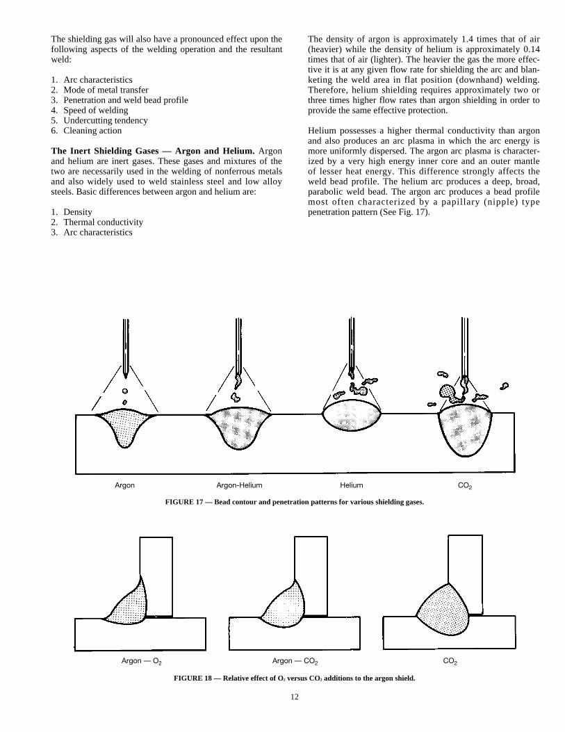
Helium possesses a higher thermal conductivity than argonand also produces an arc plasma in which the arc energy ismore uniformly dispersed. The argon arc plasma is character-ized by a very high energy inner core and an outer mantleof lesser heat energy. This difference strongly affects theweld bead profile. The helium arc produces a deep, broad,parabolic weld bead. The argon arc produces a bead profilemost often characterized by a papillary (nipple) typepenetration pattern (See Fig. 17).
FIGURE 17 — Bead contour and penetration patterns for various shielding gases.
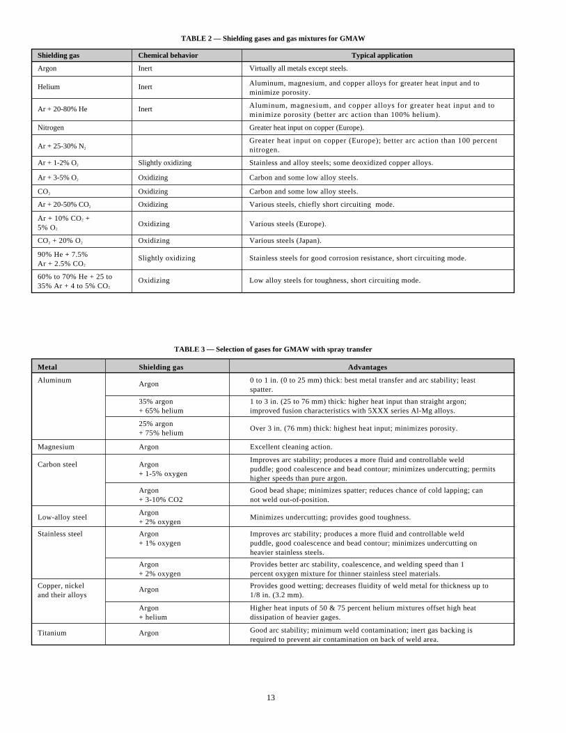
FIGURE 18 — Relative effect of O2 versus CO2 additions to the argon shield.
Argon Argon-Helium Helium CO2
Argon — O2 Argon — CO2 CO2
13
TABLE 2 — Shielding gases and gas mixtures for GMAW
TABLE 3 — Selection of gases for GMAW with spray transfer
Shielding gas Chemical behavior Typical application
Argon Inert Virtually all metals except steels.
Helium Inert Aluminum, magnesium, and copper alloys for greater heat input and to minimize porosity.
Ar + 20-80% He Inert Aluminum, magnesium, and copper alloys for greater heat input and tominimize porosity (better arc action than 100% helium).
Nitrogen Greater heat input on copper (Europe).
Ar + 25-30% N2
Greater heat input on copper (Europe); better arc action than 100 percent nitrogen.
Ar + 1-2% O2 Slightly oxidizing Stainless and alloy steels; some deoxidized copper alloys.
Ar + 3-5% O2 Oxidizing Carbon and some low alloy steels.
CO2 Oxidizing Carbon and some low alloy steels.
Ar + 20-50% CO2 Oxidizing Various steels, chiefly short circuiting mode.
Ar + 10% CO2 +Oxidizing Various steels (Europe).5% O2
CO2 + 20% O2 Oxidizing Various steels (Japan).
90% He + 7.5%Ar + 2.5% CO2
Slightly oxidizing Stainless steels for good corrosion resistance, short circuiting mode.
60% to 70% He + 25 to35% Ar + 4 to 5% CO2
Oxidizing Low alloy steels for toughness, short circuiting mode.
Metal Shielding gas Advantages
Aluminum Argon 0 to 1 in. (0 to 25 mm) thick: best metal transfer and arc stability; least spatter.
35% argon 1 to 3 in. (25 to 76 mm) thick: higher heat input than straight argon;+ 65% helium improved fusion characteristics with 5XXX series Al-Mg alloys.
25% argonOver 3 in. (76 mm) thick: highest heat input; minimizes porosity.
+ 75% helium
Magnesium Argon Excellent cleaning action.
Improves arc stability; produces a more fluid and controllable weldCarbon steel Argon
puddle; good coalescence and bead contour; minimizes undercutting; permits+ 1-5% oxygen
higher speeds than pure argon.
Argon Good bead shape; minimizes spatter; reduces chance of cold lapping; can+ 3-10% CO2 not weld out-of-position.
Low-alloy steelArgon
Minimizes undercutting; provides good toughness.+ 2% oxygen
Stainless steel Argon Improves arc stability; produces a more fluid and controllable weld+ 1% oxygen puddle, good coalescence and bead contour; minimizes undercutting on
heavier stainless steels.
Argon Provides better arc stability, coalescence, and welding speed than 1+ 2% oxygen percent oxygen mixture for thinner stainless steel materials.
Copper, nickel Argon Provides good wetting; decreases fluidity of weld metal for thickness up toand their alloys 1/8 in. (3.2 mm).
Argon Higher heat inputs of 50 & 75 percent helium mixtures offset high heat+ helium dissipation of heavier gages.
Titanium Argon Good arc stability; minimum weld contamination; inert gas backing isrequired to prevent air contamination on back of weld area.
14
At any given wire feed speed, the voltage of the argon arc willbe noticeably less than that of the helium arc. As a result,there will be less change in the voltage with respect to changein arc length for the argon arc and the arc will tend to be morestable than the helium arc. The argon arc (including mixtureswith as low as 80 percent argon) will produce an axial spraytransfer at current levels above the transition current. Thehelium-shielded arc produces a metal transfer of large dropletsin the normal operating range. Therefore, the helium arc willproduce a higher spatter level and poorer weld bead appear-ance compared to the argon arc.
The more readily ionized argon gas also facilitates arc startingand will provide superior surface cleaning action when usedwith reverse polarity (electrode positive).
Mixtures of Argon and Helium. Pure argon shielding is usedin many applications for welding nonferrous materials. Theuse of pure helium is generally restricted to more specializedareas because of its limited arc stability. However, the de-sirableweld profile characteristics (deep, broad, and parabolic)obtained with the helium arc are quite often the objective inusing an argon-helium shielding gas mixture. The result is animproved weld bead profile plus the desirable axial spraymetal transfer characteristic of argon (See Fig. 17).
In short circuiting transfer, argon-helium mixtures of from 60to 90 percent helium are used to obtain the higher heat inputinto the base metal for better fusion characteristics. Forsome metals, such as stainless and low alloy steels, heliumadditions instead of CO2 additions are chosen to obtain higherheat input, because helium will not produce weld metalreactions that could adversely affect the mechanical propertiesof the deposit.
Oxygen and CO2 Additions to Argon and Helium. Pure argonand, to some extent, helium produce excellent results in weld-ing nonferrous metals. However, these shielding gases in thepure form do not produce the most satisfactory operationalcharacteristics in welding ferrous materials. The arc tends to beerratic, accompanied by spatter with helium shielding, andshows a marked tendency to produce undercutting with pureargon shielding. Additions to argon of from 1 to 5 percent
oxygen or from 3 to 10 percent CO2 (and up to 25 percentCO2) produce a very noticeable improvement.
The optimum amount of oxygen or CO2 to be added to theinert gas is a function of the surface condition (mill scale) ofthe base metal, the joint geometry, welding position or tech-nique, and the base metal composition. Generally, 3 percentoxygen or 9 percent CO2 is considered a good compromise tocover a broad range of these variables.
Carbon dioxide additions to argon also tend to enhance theweld bead by producing a more readily defined “pear-shaped”profile (See Fig. 18).
Carbon Dioxide.Carbon dioxide (CO2) is a reactive gas widelyused in its pure form for the gas metal arc welding of carbonand low alloy steels. It is the only reactive gas suitable foruse alone as a shield in the GMAW process. Higher weldingspeed, greater joint penetration, and lower cost are generalcharacteristics which have encouraged extensive use of CO2
shielding gas.
With a CO2 shield, metal transfer is either of the short cir-cuiting or globular mode. Axial spray transfer is a character-istic of the argon shield and cannot be achieved with a CO2
shield. The globular type transfer arc is quite harsh and pro-duces a rather high level of spatter. This requires that thewelding con-ditions be set with relatively low voltage to pro-vide a very short“buried arc” (the tip of the electrode is actu-ally below the surface of the work), in order to minimizespatter.
In overall comparison to the argon-rich shielded arc, theCO2-shielded arc produces a weld bead of excellent penetrationwith a rougher surface profile and much less “washing” actionat the extremity of the weld bead due to the buried arc. Verysound weld deposits are achieved but mechanical propertiesmay be adversely affected due to the oxidizing nature of thearc.
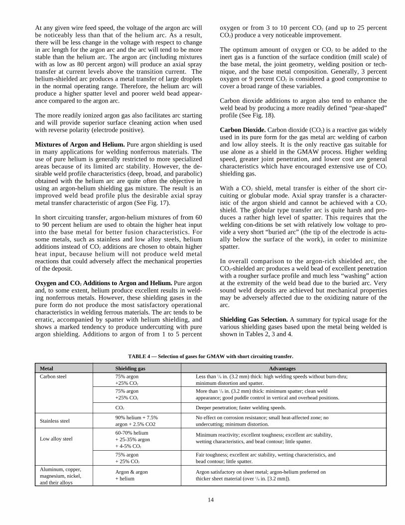
Shielding Gas Selection.A summary for typical usage for thevarious shielding gases based upon the metal being welded isshown in Tables 2, 3 and 4.
TABLE 4 — Selection of gases for GMAW with short circuiting transfer.
Metal Shielding gas Advantages
Carbon steel 75% argon Less than 1/8 in. (3.2 mm) thick: high welding speeds without burn-thru;+25% CO2 minimum distortion and spatter.
75% argon More than 1/8 in. (3.2 mm) thick: minimum spatter; clean weld+25% CO2 appearance; good puddle control in vertical and overhead positions.
CO2 Deeper penetration; faster welding speeds.
Stainless steel90% helium + 7.5% No effect on corrosion resistance; small heat-affected zone; noargon + 2.5% CO2 undercutting; minimum distortion.
60-70% helium Minimum reactivity; excellent toughness; excellent arc stability,Low alloy steel + 25-35% argon wetting characteristics, and bead contour; little spatter.
+ 4-5% CO2
75% argon Fair toughness; excellent arc stability, wetting characteristics, and+ 25% CO2 bead contour; little spatter.
Aluminum, copper, Argon & argon Argon satisfactory on sheet metal; argon-helium preferred onmagnesium, nickel, + helium thicker sheet material (over 1/8 in. [3.2 mm]).and their alloys
15
ELECTRODES
General. In the engineering of weldments, filler metals areselected to produce a weld deposit with these basic objectives:
1. A deposit closely matching the mechanical properties andphysical characteristics of the base metal
2. A sound weld deposit, free of discontinuities
Note the first objective. A weld deposit, even one of compo-sition identical to the base metal, will possess unique metal-lurgical characteristics. Therefore, the first objective of theweldment design is to produce a weld deposit compositionhaving desired properties equal to or better than those of thebase metal. The second objective is achieved, generally,through use of a filler metal electrode that was formulated toproduce a relatively defect-free deposit.
Composition.The basic filler metal composition is designed tobe compatible with one or more of the following base metalcharacteristics:
1. Chemistry2. Strength3. Ductility4. Toughness
Alternate or additional consideration may be given to otherproperties such as corrosion, heat-treatment responses, wearresistance, color match, etc. All of these considerations, how-ever, are secondary to the metallurgical compatibility of thebase metal to the filler metal.
American Welding Society (AWS) specifications have beenestablished for filler metals in common usage. Table 5 pro-vides a basic guide to some typical base-metal to filler-metalcombinations along with the applicable AWS filler metal spec-ification. Other filler metal compositions for special applica-tions, such as for high-strength steels, are available.
Formulation. The electrode must also meet certain demands ofthe process regarding arc stability, metal transfer behavior, andsolidification characteristics. Deoxidizers or other scavengingagents are always added to compensate for base metal reactionswith oxygen, nitrogen and hydrogen from the surrounding at-mosphere or the base metal. The deoxiders most frequentlyused in steel are silicon and manganese. Some steel elec-trodes may also use aluminum for additional deoxidation, aswell as titanium and zirconium for denitriding. Nickel alloyelectrodes generally use titanium and silicon for deoxidationand copper alloys will use titanium and silicon or phosphorusfor the same purpose.
Selection of Process Variables.Many process variables mustbe considered for complete application of GMAW. Thesevariables are found in the following three principle areas:
1. Equipment selection2. Mode of metal transfer and shielding gas3. Electrode selection(These three areas are very much interrelated.)
Equipment Selection.Welding equipment must meet therequirements of every application. Range of power output,
range of open circuit voltage, static and dynamic characteris-tics, wire feed speed range, etc., must correspond to the weld-ment design and the electrode size selected. Also to be con-sidered are the accessories required for the selected mode ofmetal transfer and any other special requirements.
Lincoln Electric GMAW products offer a variety of basicequipment designs and options which will produce maximumefficiency in every welding application.
When new equipment is to be purchased, some considerationshould be given to the versatility of the equipment and tostandardization. Selection of equipment for single-purpose orhigh volume production can generally be based upon the re-quirements of that particular application only. However, ifmultiples of jobs are to be performed (as in job shop opera-tion), many of which may be unknown at the time of selection,versatility is very important. Other equipment already in use atthe facility should be considered. Standardizing certain com-ponents and complementing existing equipment will minimizeinventory requirements and provide maximum efficiency ofoverall operation.
Mode of Metal Transfer and Shielding Gas.The characteristicsof the mode of metal transfer are very important in analysis ofthe process application. Characteristics such as weld beadprofile, reinforcement shape, spatter, etc., are relevant to theweldment design. The following major considerations reflectthe importance of these characteristics.
Design and Service Performance.Product design, as well asspecific weld joint design, requires consideration of penetra-tion and reinforcement profiles. Both static and dynamic serv-ice performance requirements may dictate the need foradditional strength (in the form of penetration) or minimalstress concentration (good “wash” characteristics). The shield-ing gas selected is very important in determining these basiccharacteristics.
Process Control.Material thickness may require using the lowenergy short circuit transfer mode rather than either the sprayor globular transfer mode with their inherently higher energyinput. Joint fit-up tolerances (gap) and weld size and lengthmay also be a major influence in selection of the process modeto be used.
The designed weld bead profile (including reinforcement,fusion pattern, and penetration) can be controlled by theshielding gas selection. Proper shielding gas selection can bean important factor to assure, for instance, good fusion charac-teristics when a welder may be “extended” to reach a difficultlocation and unable to maintain his gun in an optimumposition.
Appearance.The appearance of the weldment is not of tech-nical concern but may be important. Smooth and spatter-freeweld beads on a product in an area highlighted in the pur-chaser’s view are cited as a sales factor in many instances. Thespray arc and the short circuiting modes of metal transfer willproduce the smoothest and neatest-appearing welds. Smoothand spatter-free areas adjacent to GMAW welds may also berequired to assure proper fits in subsequent final assemblyoperations.
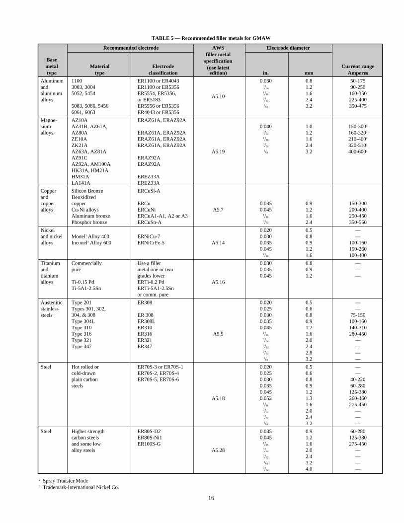
Recommended electrode AWS Electrode diameterfiller metal
Base specificationmetal Material Electrode (use latest Current rangetype type classification edition) in. mm Amperes
Aluminum 1100 ER1100 or ER4043 0.030 0.8 50-175and 3003, 3004 ER1100 or ER5356 3/64 1.2 90-250aluminum 5052, 5454 ER5554, ER5356, 1/16 1.6 160-350alloys or ER5183
A5.103/32 2.4 225-400
5083, 5086, 5456 ER5556 or ER5356 1/8 3.2 350-4756061, 6063 ER4043 or ER5356
Magne- AZ10A ERAZ61A, ERAZ92Asium AZ31B, AZ61A, 0.040 1.0 150-3002
alloys AZ80A ERAZ61A, ERAZ92A 3/64 1.2 160-3202
ZE10A ERAZ61A, ERAZ92A 1/16 1.6 210-4002
ZK21A ERAZ61A, ERAZ92A 3/32 2.4 320-5102
AZ63A, AZ81A A5.19 1/8 3.2 400-6002
AZ91C ERAZ92AAZ92A, AM100A ERAZ92AHK31A, HM21AHM31A EREZ33ALA141A EREZ33A
Copper Silicon Bronze ERCuSi-Aand Deoxidizedcopper copper ERCu 0.035 0.9 150-300alloys Cu-Ni alloys ERCuNi A5.7 0.045 1.2 200-400
Aluminum bronze ERCuA1-A1, A2 or A3 1/16 1.6 250-450Phosphor bronze ERCuSn-A 3/32 2.4 350-550
Nickel 0.020 0.5 —and nickel Monel3 Alloy 400 ERNiCu-7 0.030 0.8 —alloys Inconel3 Alloy 600 ERNiCrFe-5 A5.14 0.035 0.9 100-160
0.045 1.2 150-2601/16 1.6 100-400
Titanium Commercially Use a filler 0.030 0.8 —and pure metal one or two 0.035 0.9 —titanium grades lower 0.045 1.2 —alloys Ti-0.15 Pd ERTi-0.2 Pd A5.16
Ti-5A1-2.5Sn ERTi-5A1-2.5Snor comm. pure
Austenitic Type 201 ER308 0.020 0.5 —stainless Types 301, 302, 0.025 0.6 —steels 304, & 308 ER 308 0.030 0.8 75-150
Type 304L ER308L 0.035 0.9 100-160Type 310 ER310 0.045 1.2 140-310Type 316 ER316 A5.9 1/16 1.6 280-450Type 321 ER321 5/64 2.0 —Type 347 ER347 3/32 2.4 —
7/64 2.8 —1/8 3.2 —
Steel Hot rolled or ER70S-3 or ER70S-1 0.020 0.5 —cold-drawn ER70S-2, ER70S-4 0.025 0.6 —plain carbon ER70S-5, ER70S-6 0.030 0.8 40-220steels 0.035 0.9 60-280
0.045 1.2 125-380A5.18 0.052 1.3 260-460
1/16 1.6 275-4505/64 2.0 —3/32 2.4 —1/8 3.2 —
Steel Higher strength ER80S-D2 0.035 0.9 60-280carbon steels ER80S-Ni1 0.045 1.2 125-380and some low ER100S-G 1/16 1.6 275-450alloy steels A5.28 5/64 2.0 —
3/32 2.4 —1/8 3.2 —5/32 4.0 —
16
TABLE 5 — Recommended filler metals for GMAW
2 Spray Transfer Mode3 Trademark-International Nickel Co.

17
Electrode selection.The selection of the welding electrodeshould be based principally upon matching the mechanicalproperties and the physical characteristics of the base metal(See Table 5). Secondary considerations should be given toitemssuch as the equipment to be used, the weld size (deposi-tion rates to be utilized), existing electrode inventory, andmaterials handling systems.
Lincoln Electric offers a choice of electrode compositions.For welding mill steel with the GMAW process, L-50 is thepreferred electrode. It has excellent feedability through gunand cable systems. L-50 conforms to AWS classificationER70S-3.
L-54 is designed for improved operation versus L-50 for weld-ing over small amounts of rust and dirt, but still not as muchas L-56. L-54 conforms to AWS classification ER70S-4.
L-52 is triple deoxidized with aluminum, titanium, and zirco-nium in addition to manganese and silicon. It produces lessfluid weld metal which makes it ideal for welding out-of-position and for welding small diameter pipe. L-52 conformsto AWS classification ER70S-2.
For best performance on rusty or dirty surfaces, L-56 is thepreferred choice. It conforms to AWS classification ER70S-6.
L-50B, L-54B and L-56B are non-copper coated versions ofeach respective electrode, and are recommended for applica-tions where non-coated electrodes are preferred.
LA-75 is designed for use on applications requiring excellentlow temperature impacts and on weathering steels. It con-forms to AWS classification ER80S-Ni1.
LA-90 is designed for welding on high strength steels whereweld tensile strengths of 90,000 psi (620 mPa) or higher arerequired. LA-90 conforms to AWS ER80S-D-2 and ER90S-Gclassification per A5.28.
LA-100 electrode is designed for welding high strength, lowalloy steels. LA-100 conforms to ER100S-G per A5.28 andalso meets the requirements of ER110S-G. It is also approvedas an MIL-100S-1 classification.
For gas metal arc welding of stainless steels, Lincoln Electricoffers Blue Max MIG 308LSi, 309LSi and 316LSi. All areclassified per AWS A5.9. For further information on theseelectrodes consult Lincoln bulletin C6.1.
In addition, there are numerous other Lincoln electrodes to sat-isfy the specific requirements of other welding applications.Consult your local Lincoln distributor for detailed information.
Equipment. The electrode package size should be compatiblewith the available handling equipment. The package sizeshould be determined by a cost evaluation that considers prod-uct volume, change time versus the consideration of availablespace, inventory cost, and the materials handling system.
Weld Size.The electrode diameter should be chosen to best fitthe requirements of the weld size and the deposition rate tobe used. In general, it is economically advantageous to usethe largest diameter possible.
Standardization and Inventory. Evaluation of each welding jobon its own individual merit would require an increasinglylarger inventory with an increasing number of jobs. Mini-mizeing inventory requires a review of overall welding require-ments in the plant, with standardization of the basic electrodecom-position and sizes as well as the electrode packages as theobjective. This can be accomplished readily with minimumcompromise since quite broad and overlapping choices areavailable.
Materials Handling Systems.The electrode package size shouldalso take into account the requirements for handling. Generallyspeaking, one individual can be expected to change an elec-trode package weighing up to 60 lb (27 kg) without assistance.However, some systems are designed so that an individual canhandle the larger reels up to 1000 lb (454 kg) without additionalassistance. The larger packages necessitate a handling system(lift truck or similar) capable of moving the electrode packagefrom storage to the welding station when required for changing,or additional space is needed to accommodate at least twopackages in order to avoid delays.
Lincoln electrodes are available in various packagearrangements to facilitate individual production and handlingrequirements.
Consult your local Lincoln office or distributor for completeelectrode type and packaging information.
Operating Conditions. After selecting the basic process vari-ables, the basic operating conditions to be met are as follows:
1. Deposition rate — travel speed2. Wire feed speed (welding current)3. Welding voltage4. Electrode extension (stickout)
Deposition Rate.The deposition rate is defined as the actualamount of weld metal deposited per unit of time (generally interms of pounds (kilograms) per hour). It is necessary to bal-ance the deposition rate against the travel speed, since properbalance achieves an optimum rate of metal deposition for theweld joint design. This is particularly important in semiau-tomatic welding when weld quality depends upon the physicalmovement capability of the welder. The following factorsaffect this balanced relationship:
1. Weld size2. Weld joint design3. Number of weld passes4. Physical limitation of the welder (in semiautomatic weld-
ing) to retain control of the weld puddle as travel speed isincreased to keep weld metal from “overrunning” the arc.This maximum limitation is typically around 25 in./min(.6 m/min) although in many reported instances the travelspeed may reach as high as 150 in./min (3.8 m/min). Ingeneral, these higher rates of travel speed are attainablewhen the weld size is very small, the weld length is veryshort, the weld is along a straight line, or when optimumweld appearance is not a factor.
18
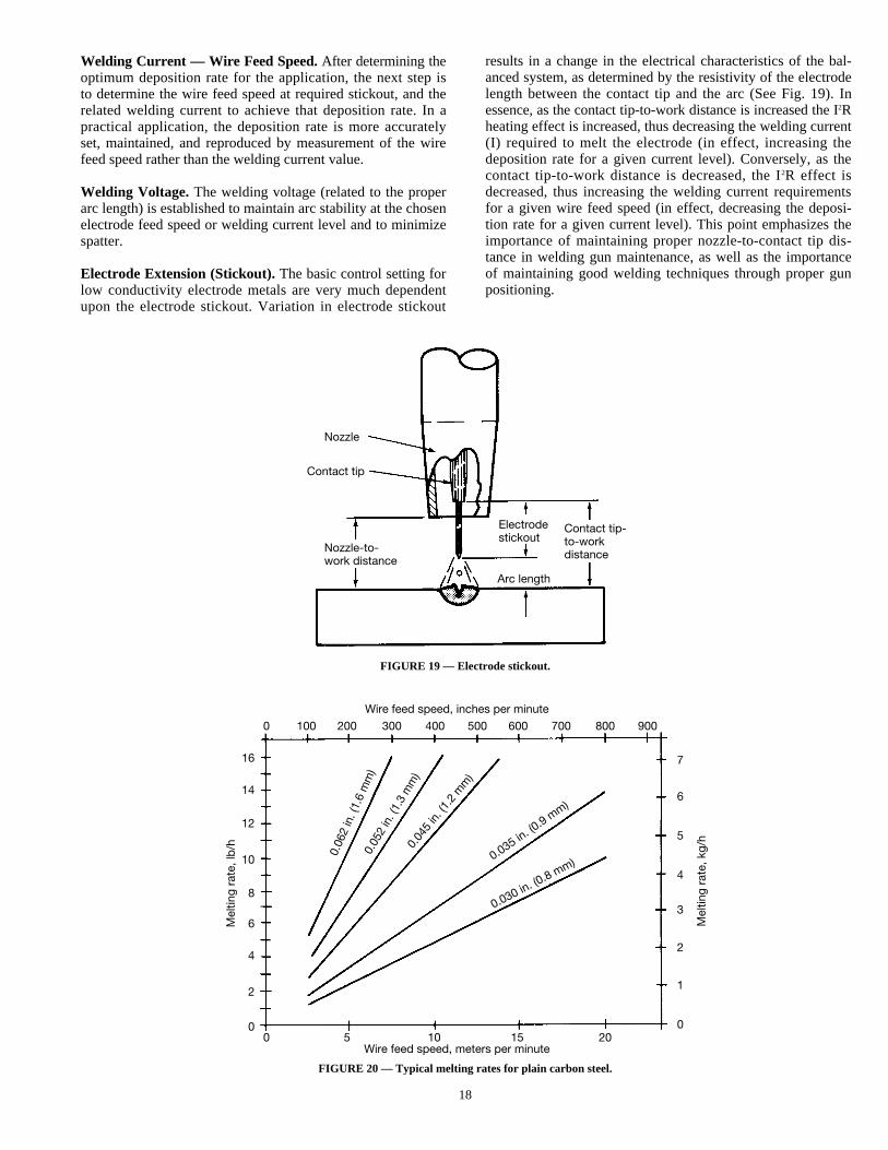
FIGURE 20 — Typical melting rates for plain carbon steel.
FIGURE 19 — Electrode stickout.
Nozzle
Contact tip
Nozzle-to-work distance
Electrodestickout
Contact tip-to-workdistance
Arc length
Wire feed speed, inches per minute
0 100 200 300 400 500 600 700 800 900
16
14
12
10
8
6
4
2
0
7
6
5
4
3
2
1
00 5 10 15 20
Mel
ting
rate
, lb
/h
Mel
ting
rate
, kg/
h
0.06
2 in
. (1.
6 m
m)
0.05
2 in
. (1.
3 m
m)
0.04
5 in
. (1.
2 m
m)
0.035 in. (0
.9 mm)
0.030 in. (0.8 mm)
Wire feed speed, meters per minute
results in a change in the electrical characteristics of the bal-anced system, as determined by the resistivity of the electrodelength between the contact tip and the arc (See Fig. 19). Inessence, as the contact tip-to-work distance is increased the I2Rheating effect is increased, thus decreasing the welding current(I) required to melt the electrode (in effect, increasing thedeposition rate for a given current level). Conversely, as thecontact tip-to-work distance is decreased, the I2R effect isdecreased, thus increasing the welding current requirementsfor a given wire feed speed (in effect, decreasing the deposi-tion rate for a given current level). This point emphasizes theimportance of maintaining proper nozzle-to-contact tip dis-tance in welding gun maintenance, as well as the importanceof maintaining good welding techniques through proper gunpositioning.
Welding Current — Wire Feed Speed.After determining theoptimum deposition rate for the application, the next step isto determine the wire feed speed at required stickout, and therelated welding current to achieve that deposition rate. In apractical application, the deposition rate is more accuratelyset, maintained, and reproduced by measurement of the wirefeed speed rather than the welding current value.
Welding Voltage. The welding voltage (related to the properarc length) is established to maintain arc stability at the chosenelectrode feed speed or welding current level and to minimizespatter.
Electrode Extension (Stickout).The basic control setting forlow conductivity electrode metals are very much dependentupon the electrode stickout. Variation in electrode stickout
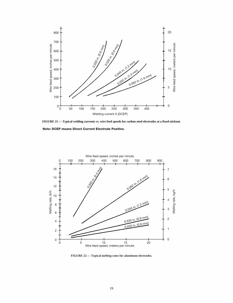
19
FIGURE 21 — Typical welding currents vs. wire feed speeds for carbon steel electrodes at a fixed stickout.
Note: DCEP means Direct Current Electrode Positive.
FIGURE 22 — Typical melting rates for aluminum electrodes.
800
700
600
500
400
300
200
100
0
20
15
10
5
00 50 100 150 200 250 300 350 400
Wire
feed
sp
eed
, inc
hes
per
min
ute
Wire
feed
sp
eed
, met
ers
per
min
ute
0.03
0 in
. (0.
8 m
m)
0.03
5 in
. (0.
9 m
m)
0.045 in. (1
.2 mm)
0.052 in. (1
.3 mm)
0.062 in. (1.6 mm)
Welding current A (DCEP)
Wire feed speed, inches per minute
0 100 200 300 400 500 600 700 800 900
16
14
12
10
8
6
4
2
0
7
6
5
4
3
2
1
00 5 10 15 20
Mel
ting
rate
, lb
/h
Mel
ting
rate
, kg/
h
0.09
3 in
. (2.
4 m
m)
0.062 in. (1
.6 mm)
0.045 in. (1.2 mm)
0.035 in. (0.9 mm)
0.030 in. (0.8 mm)
Wire feed speed, meters per minute
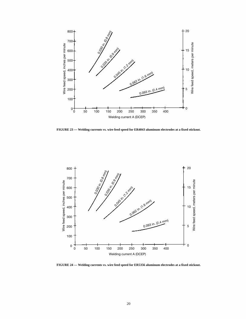
20
FIGURE 23 — Welding currents vs. wire feed speed for ER4043 aluminum electrodes at a fixed stickout.
800
700
600
500
400
300
200
100
0
20
15
10
5
00 50 100 150 200 250 300 350 400
Wire
feed
sp
eed
, inc
hes
per
min
ute
Wire
feed
sp
eed
, met
ers
per
min
ute
0.03
0 in
. (0.
8 m
m)
0.03
5 in
. (0.
9 m
m)
0.045
in. (1
.2 m
m)
0.062 in. (1.6 mm)
0.093 in. (2.4 mm)
Welding current A (DCEP)
800
700
600
500
400
300
200
100
0
20
15
10
5
00 50 100 150 200 250 300 350 400
Wire
feed
sp
eed
, inc
hes
per
min
ute
Wire
feed
sp
eed
, met
ers
per
min
ute
0.03
0 in
. (0.
8 m
m)
0.03
5 in
. (0.
9 m
m)
0.04
5 in.
(1.2
mm
)
0.062 in. (1
.6 mm)
0.093 in. (2.4 mm)
Welding current A (DCEP)
FIGURE 24 — Welding currents vs. wire feed speed for ER5356 aluminum electrodes at a fixed stickout.
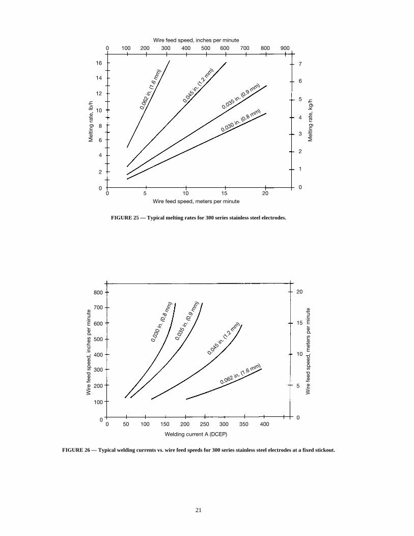
21
FIGURE 25 — Typical melting rates for 300 series stainless steel electrodes.
Wire feed speed, inches per minute
0 100 200 300 400 500 600 700 800 900
16
14
12
10
8
6
4
2
0
7
6
5
4
3
2
1
00 5 10 15 20
Mel
ting
rate
, lb
/h
Mel
ting
rate
, kg/
h
0.06
2 in
. (1.
6 m
m)
0.04
5 in
. (1.
2 m
m)
0.035 in. (0.9 m
m)
0.030 in. (0.8 mm)
Wire feed speed, meters per minute
800
700
600
500
400
300
200
100
0
20
15
10
5
00 50 100 150 200 250 300 350 400
Wire
feed
sp
eed
, inc
hes
per
min
ute
Wire
feed
sp
eed
, met
ers
per
min
ute
0.03
0 in
. (0.
8 m
m)
0.03
5 in
. (0.
9 m
m)
0.04
5 in.
(1.2
mm
)
0.062 in. (1.6 mm)
Welding current A (DCEP)
FIGURE 26 — Typical welding currents vs. wire feed speeds for 300 series stainless steel electrodes at a fixed stickout.
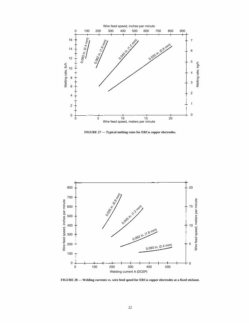
22
FIGURE 28 — Welding currents vs. wire feed speed for ERCu copper electrodes at a fixed stickout.
800
700
600
500
400
300
200
100
0
20
15
10
5
00 100 200 300 400 500
Wire
feed
sp
eed
, inc
hes
per
min
ute
Wire
feed
sp
eed
, met
ers
per
min
ute
0.03
5 in
. (0.
9 m
m)
0.045
in. (1
.2 m
m)
0.062 in. (1.6 mm)
0.093 in. (2.4 mm)
Welding current A (DCEP)
Wire feed speed, inches per minute
0 100 200 300 400 500 600 700 800 900
16
14
12
10
8
6
4
2
0
7
6
5
4
3
2
1
00 5 10 15 20
Mel
ting
rate
, lb
/h
Mel
ting
rate
, kg/
h0.09
3 in
. (2.
4 m
m)
0.06
2 in
. (1.
6 m
m)
0.04
5 in
. (1.
2 m
m)
0.035 in. (0
.9 mm)
Wire feed speed, meters per minute
FIGURE 27 — Typical melting rates for ERCu copper electrodes.
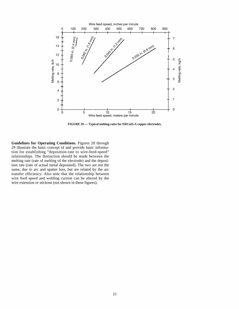
23
FIGURE 29 — Typical melting rates for ERCuSi-A copper electrodes.
Guidelines for Operating Conditions. Figures 20 through29 illustrate the basic concept of and provide basic informa-tion for establishing “deposition-rate to wire-feed-speed”relationships. The distinction should be made between themelting rate (rate of melting of the electrode) and the deposi-tion rate (rate of actual metal deposited). The two are not thesame, due to arc and spatter loss, but are related by the arctransfer efficiency. Also note that the relationship betweenwire feed speed and welding current can be altered by thewire extension or stickout (not shown in these figures).
Wire feed speed, inches per minute
0 100 200 300 400 500 600 700 800 900
16
14
12
10
8
6
4
2
0
7
6
5
4
3
2
1
00 5 10 15 20
Mel
ting
rate
, lb
/h
Mel
ting
rate
, kg/
h
0.09
3 in
. (2.
4 m
m)
0.06
2 in
. (1.
6 m
m)
0.04
5 in
. (1.
2 m
m)
0.035 in. (0.9 m
m)
Wire feed speed, meters per minute
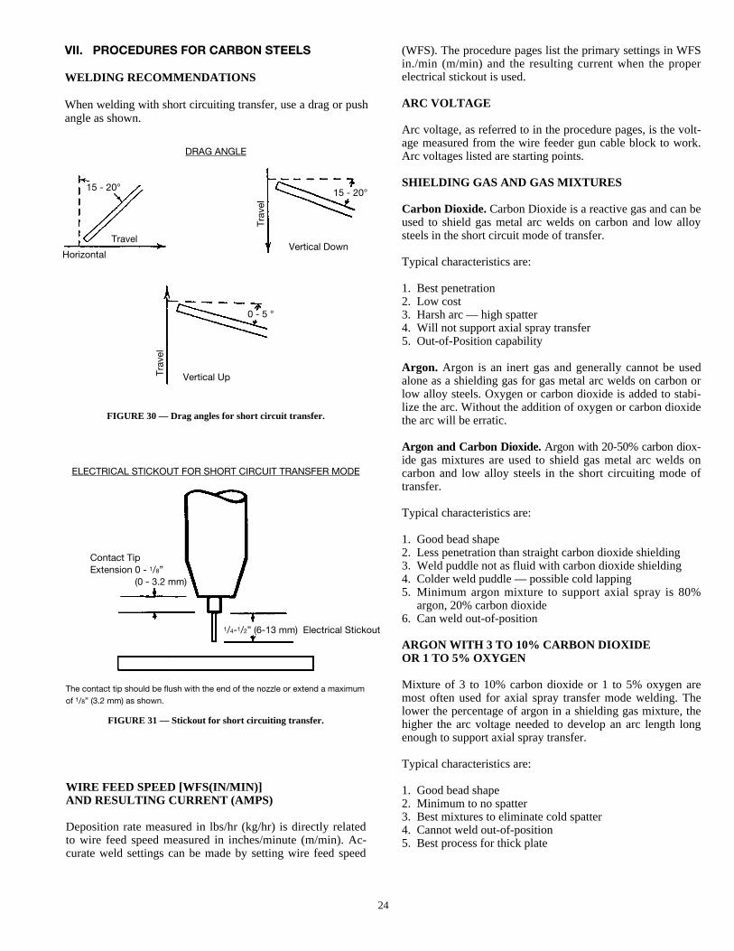
24
VII. PROCEDURES FOR CARBON STEELS
WELDING RECOMMENDATIONS
When welding with short circuiting transfer, use a drag or pushangle as shown.
(WFS). The procedure pages list the primary settings in WFSin./min (m/min) and the resulting current when the properelectrical stickout is used.
ARC VOLTAGE
Arc voltage, as referred to in the procedure pages, is the volt-age measured from the wire feeder gun cable block to work.Arc voltages listed are starting points.
SHIELDING GAS AND GAS MIXTURES
Carbon Dioxide. Carbon Dioxide is a reactive gas and can beused to shield gas metal arc welds on carbon and low alloysteels in the short circuit mode of transfer.
Typical characteristics are:
1. Best penetration2. Low cost3. Harsh arc — high spatter4. Will not support axial spray transfer5. Out-of-Position capability
Argon. Argon is an inert gas and generally cannot be usedalone as a shielding gas for gas metal arc welds on carbon orlow alloy steels. Oxygen or carbon dioxide is added to stabi-lize the arc. Without the addition of oxygen or carbon dioxidethe arc will be erratic.
Argon and Carbon Dioxide.Argon with 20-50% carbon diox-ide gas mixtures are used to shield gas metal arc welds oncarbon and low alloy steels in the short circuiting mode oftransfer.
Typical characteristics are:
1. Good bead shape2. Less penetration than straight carbon dioxide shielding3. Weld puddle not as fluid with carbon dioxide shielding 4. Colder weld puddle — possible cold lapping5. Minimum argon mixture to support axial spray is 80%
argon, 20% carbon dioxide6. Can weld out-of-position
ARGON WITH 3 TO 10% CARBON DIOXIDE OR 1 TO 5% OXYGEN
Mixture of 3 to 10% carbon dioxide or 1 to 5% oxygen aremost often used for axial spray transfer mode welding. Thelower the percentage of argon in a shielding gas mixture, thehigher the arc voltage needed to develop an arc length longenough to support axial spray transfer.
Typical characteristics are:
1. Good bead shape2. Minimum to no spatter3. Best mixtures to eliminate cold spatter4. Cannot weld out-of-position5. Best process for thick plate
FIGURE 30 — Drag angles for short circuit transfer.
FIGURE 31 — Stickout for short circuiting transfer.
DRAG ANGLE
15 - 20° 15 - 20°
0 - 5 °
Travel
Trav
el
Trav
el
HorizontalVertical Down
Vertical Up
ELECTRICAL STICKOUT FOR SHORT CIRCUIT TRANSFER MODE
Contact TipExtension 0 - 1/8”
(0 - 3.2 mm)
1/4-1/2” (6-13 mm) Electrical Stickout
The contact tip should be flush with the end of the nozzle or extend a maximumof 1/8” (3.2 mm) as shown.
WIRE FEED SPEED [WFS(IN/MIN)]AND RESULTING CURRENT (AMPS)
Deposition rate measured in lbs/hr (kg/hr) is directly relatedto wire feed speed measured in inches/minute (m/min). Ac-curate weld settings can be made by setting wire feed speed
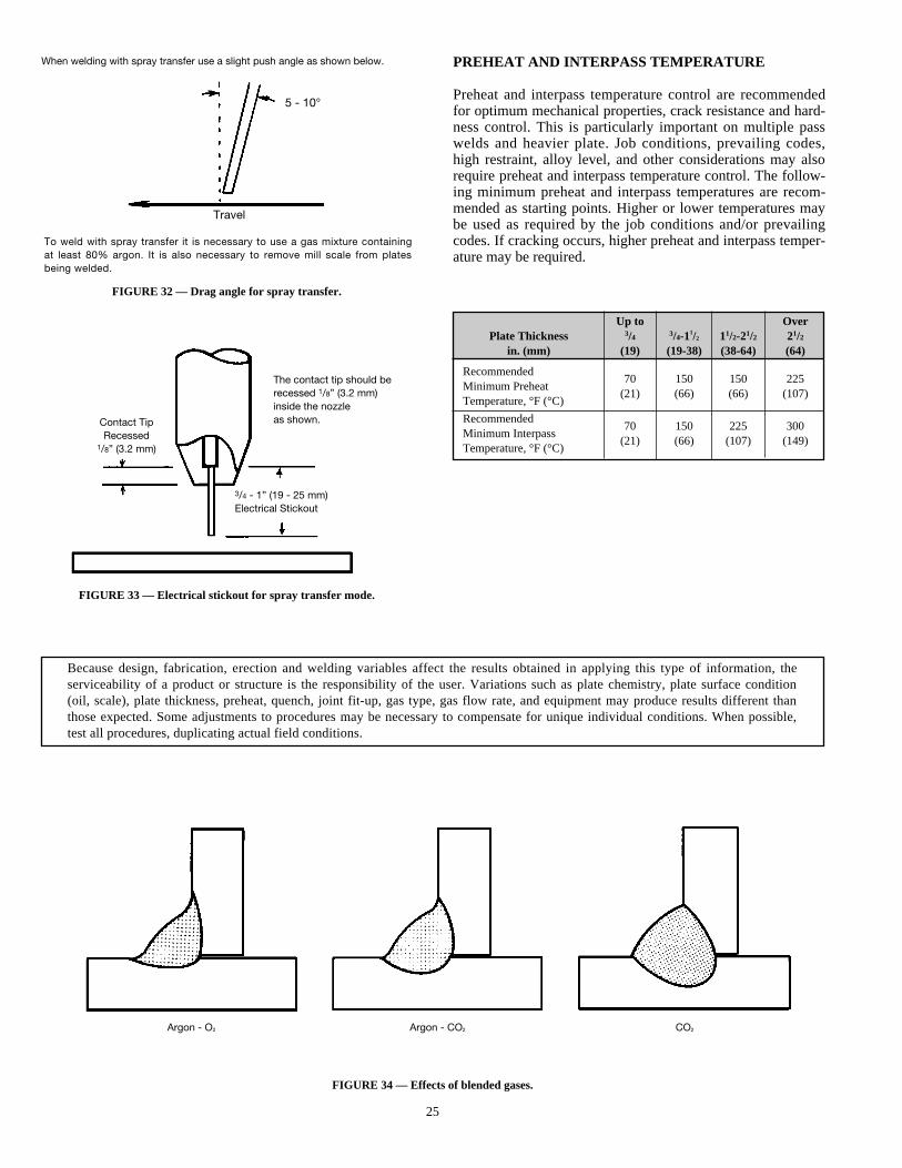
25
FIGURE 32 — Drag angle for spray transfer.
FIGURE 33 — Electrical stickout for spray transfer mode.
FIGURE 34 — Effects of blended gases.
PREHEAT AND INTERPASS TEMPERATURE
Preheat and interpass temperature control are recommendedfor optimum mechanical properties, crack resistance and hard-ness control. This is particularly important on multiple passwelds and heavier plate. Job conditions, prevailing codes,high restraint, alloy level, and other considerations may alsorequire preheat and interpass temperature control. The follow-ing minimum preheat and interpass temperatures are recom-mended as starting points. Higher or lower temperatures maybe used as required by the job conditions and/or prevailingcodes. If cracking occurs, higher preheat and interpass temper-ature may be required.
Because design, fabrication, erection and welding variables affect the results obtained in applying this type of information, theserviceability of a product or structure is the responsibility of the user. Variations such as plate chemistry, plate surface condition(oil, scale), plate thickness, preheat, quench, joint fit-up, gas type, gas flow rate, and equipment may produce results different thanthose expected. Some adjustments to procedures may be necessary to compensate for unique individual conditions. When possible,test all procedures, duplicating actual field conditions.
When welding with spray transfer use a slight push angle as shown below.
To weld with spray transfer it is necessary to use a gas mixture containingat least 80% argon. It is also necessary to remove mill scale from platesbeing welded.
Contact TipRecessed
1/8” (3.2 mm)
The contact tip should berecessed 1/8” (3.2 mm)inside the nozzleas shown.
3/4 - 1” (19 - 25 mm)Electrical Stickout
Travel
Argon - O2 Argon - CO2 CO2
5 - 10°
Up to OverPlate Thickness 3/4 3/4-11/2 11/2-21/2 21/2
in. (mm) (19) (19-38) (38-64) (64)
Recommended70 150 150 225
Minimum Preheat(21) (66) (66) (107)
Temperature, °F (°C)
Recommended70 150 225 300
Minimum Interpass(21) (66) (107) (149)
Temperature, °F (°C)
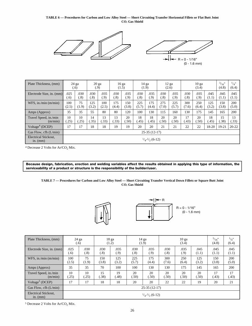
26
TABLE 6 — Procedures for Carbon and Low Alloy Steel — Short Circuiting Transfer Horizontal Fillets or Flat Butt JointCO2 Gas Shield
TABLE 7 — Procedures for Carbon and Low Alloy Steel — Short Circuiting Transfer Vertical Down Fillets or Square Butt JointCO2 Gas Shield
Because design, fabrication, erection and welding variables affect the results obtained in applying this type of information, theserviceability of a product or structure is the responsibility of the builder/user.
Plate Thickness, (mm) 24 ga 20 ga 16 ga 14 ga 12 ga 10 ga 3/16" 1/4"(.6) (.9) (1.5) (1.9) (2.6) (3.4) (4.8) (6.4)
Electrode Size, in. (mm) .025 .030 .030 .035 .030 .035 .030 .035 .030 .035 .030 .035 .045 .045 .045(.6) (.8) (.8) (.9) (.8) (.9) (.8) (.9) (.8) (.9) (.8) (.9) (1.1) (1.1) (1.1)
WFS, in./min (m/min) 100 75 125 100 175 150 225 175 275 225 300 250 125 150 200(2.5) (1.9) (3.2) (2.5) (4.4) (3.8) (5.7) (4.4) (7.0) (5.7) (7.6) (6.4) (3.2) (3.8) (5.0)
Amps (Approx) 35 35 55 80 80 120 100 130 115 160 130 175 145 165 200
Travel Speed, in./min 10 10 14 13 13 20 18 18 20 20 17 20 18 15 13(m/min) (.25) (.25) (.35) (.33) (.33) (.50) (.45) (.45) (.50) (.50) (.43) (.50) (.45) (.38) (.33)
Voltage4 (DCEP) 17 17 18 18 19 19 20 20 21 21 22 22 18-20 19-21 20-22
Gas Flow, cfh (L/min) 25-35 (12-17)Electrical Stickout,
1/4-1/2 (6-12)in. (mm)
4 Decrease 2 Volts for Ar/CO2 Mix.
Plate Thickness, (mm) 24 ga 18 ga 14 ga 10 ga 3/16" 1/4"(.6) (1.2) (1.9) (3.4) (4.8) (6.4)
Electrode Size, in. (mm) .025 .030 .030 .035 .030 .035 .030 .035 .045 .045 .045(.6) (.8) (.8) (.9) (.8) (.9) (.8) (.9) (1.1) (1.1) (1.1)
WFS, in./min (m/min) 100 75 150 125 225 175 300 250 125 150 200(2.5) (1.9) (3.8) (3.2) (5.7) (4.4) (7.6) (6.4) (3.2) (3.8) (5.0)
Amps (Approx) 35 35 70 100 100 130 130 175 145 165 200
Travel Speed, in./min 10 10 15 19 20 20 20 20 20 17 17(m/min) (.25) (.25) (.38) (.48) (.50) (.50) (.50) (.50) (.50) (.43) (.43)
Voltage5 (DCEP) 17 17 18 18 20 20 22 22 19 20 21
Gas Flow, cfh (L/min) 25-35 (12-17)
Electrical Stickout, 1/4-1/2 (6-12)in. (mm)
5 Decrease 2 Volts for Ar/CO2 Mix.
R = 0 - 1/16”(0 - 1.6 mm)
R = 0 - 1/16”(0 - 1.6 mm)
R
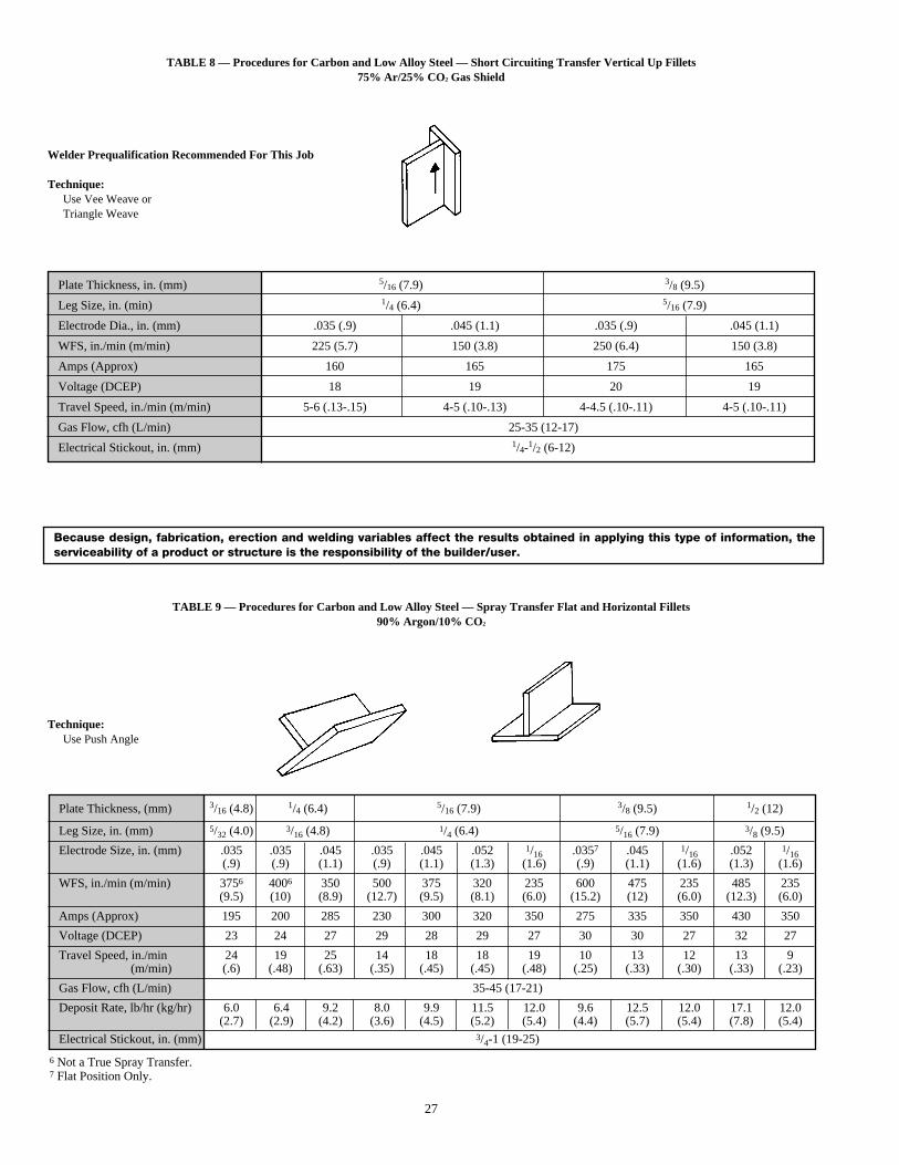
27
TABLE 8 — Procedures for Carbon and Low Alloy Steel — Short Circuiting Transfer Vertical Up Fillets75% Ar/25% CO 2 Gas Shield
TABLE 9 — Procedures for Carbon and Low Alloy Steel — Spray Transfer Flat and Horizontal Fillets90% Argon/10% CO2
Because design, fabrication, erection and welding variables affect the results obtained in applying this type of information, theserviceability of a product or structure is the responsibility of the builder/user.
Plate Thickness, (mm) 3/16 (4.8) 1/4 (6.4) 5/16 (7.9) 3/8 (9.5) 1/2 (12)
Leg Size, in. (mm) 5/32 (4.0) 3/16 (4.8) 1/4 (6.4) 5/16 (7.9) 3/8 (9.5)
Electrode Size, in. (mm) .035 .035 .045 .035 .045 .052 1/16 .0357 .045 1/16 .052 1/16(.9) (.9) (1.1) (.9) (1.1) (1.3) (1.6) (.9) (1.1) (1.6) (1.3) (1.6)
WFS, in./min (m/min) 3756 4006 350 500 375 320 235 600 475 235 485 235(9.5) (10) (8.9) (12.7) (9.5) (8.1) (6.0) (15.2) (12) (6.0) (12.3) (6.0)
Amps (Approx) 195 200 285 230 300 320 350 275 335 350 430 350
Voltage (DCEP) 23 24 27 29 28 29 27 30 30 27 32 27
Travel Speed, in./min 24 19 25 14 18 18 19 10 13 12 13 9(m/min) (.6) (.48) (.63) (.35) (.45) (.45) (.48) (.25) (.33) (.30) (.33) (.23)
Gas Flow, cfh (L/min) 35-45 (17-21)
Deposit Rate, lb/hr (kg/hr) 6.0 6.4 9.2 8.0 9.9 11.5 12.0 9.6 12.5 12.0 17.1 12.0(2.7) (2.9) (4.2) (3.6) (4.5) (5.2) (5.4) (4.4) (5.7) (5.4) (7.8) (5.4)
Electrical Stickout, in. (mm) 3/4-1 (19-25)
6 Not a True Spray Transfer.7 Flat Position Only.
Plate Thickness, in. (mm) 5/16 (7.9) 3/8 (9.5)
Leg Size, in. (min) 1/4 (6.4) 5/16 (7.9)
Electrode Dia., in. (mm) .035 (.9) .045 (1.1) .035 (.9) .045 (1.1)
WFS, in./min (m/min) 225 (5.7) 150 (3.8) 250 (6.4) 150 (3.8)
Amps (Approx) 160 165 175 165
Voltage (DCEP) 18 19 20 19
Travel Speed, in./min (m/min) 5-6 (.13-.15) 4-5 (.10-.13) 4-4.5 (.10-.11) 4-5 (.10-.11)
Gas Flow, cfh (L/min) 25-35 (12-17)
Electrical Stickout, in. (mm) 1/4-1/2 (6-12)
Welder Prequalification Recommended For This Job
Technique:Use Vee Weave orTriangle Weave
Technique:Use Push Angle
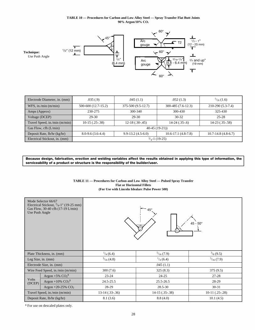
28
TABLE 10 — Procedures for Carbon and Low Alloy Steel — Spray Transfer Flat Butt Joints90% Argon/10% CO2
TABLE 11 — Procedures for Carbon and Low Alloy Steel — Pulsed Spray TransferFlat or Horizontal Fillets
(For Use with Lincoln Idealarc Pulse Power 500)
Because design, fabrication, erection and welding variables affect the results obtained in applying this type of information, theserviceability of a product or structure is the responsibility of the builder/user.
Electrode Diameter, in. (mm) .035 (.9) .045 (1.1) .052 (1.3) 1/16 (1.6)
WFS, in./min (m/min) 500-600 (12.7-15.2) 375-500 (9.5-12.7) 300-485 (7.6-12.3) 210-290 (5.3-7.4)
Amps (Approx) 230-275 300-340 300-430 325-430
Voltage (DCEP) 29-30 29-30 30-32 25-28
Travel Speed, in./min (m/min) 10-15 (.25-.38) 12-18 (.30-.45) 14-24 (.35-.6) 14-23 (.35-.58)
Gas Flow, cfh (L/min) 40-45 (19-21))
Deposit Rate, lb/hr (kg/hr) 8.0-9.6 (3.6-4.4) 9.9-13.2 (4.5-6.0) 10.6-17.1 (4.8-7.8) 10.7-14.8 (4.8-6.7)
Electrical Stickout, in. (mm) 3/4-1 (19-25)
Mode Selector 66/67Electrical Stickout, 3/4-1" (19-25 mm)Gas Flow, 30-40 cfh (17-19 L/min)Use Push Angle
Plate Thickness, in. (mm) 1/4 (6.4) 5/16 (7.9) 3/8 (9.5)
Leg Size, in. (mm) 3/16 (4.8) 1/4 (6.4) 5/16 (7.9)
Electrode Size, in. (mm) .045 (1.1)
Wire Feed Speed, in./min (m/min) 300 (7.6) 325 (8.3) 375 (9.5)
VoltsArgon +5% CO2
8 23-24 24-25 27-28
(DCEP) Argon +10% CO28 24.5-25.5 25.5-26.5 28-29
Argon +20-25% CO2 28-29 28.5-30 30-31
Travel Speed, in./min (m/min) 13-14 (.33-.36) 14-15 (.35-.38) 10-11 (.25-.28)
Deposit Rate, lb/hr (kg/hr) 8.1 (3.6) 8.8 (4.0) 10.1 (4.5)
8 For use on descaled plates only.
1/2” (12 mm)
45°
45 - 50°
Arcgouge
Arcgouge
45°
60°
60°
60°
T21/2 - 1”
(12 - 25 mm)
3/4 and up”(19 mm)
Technique:Use Push Angle
1/4”(6.4 mm)
3/16-1/4”(4.8 - 6.4 mm)
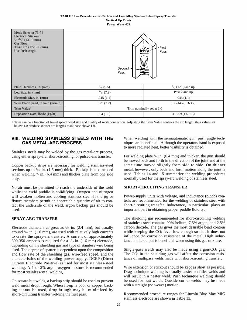
29
TABLE 12 — Procedures for Carbon and Low Alloy Steel — Pulsed Spray TransferVertical Up FilletsPower Wave 455
Mode Selector 73-74Electrical Stickout,1/2-3/4" (13-19 mm)Gas Flow,30-40 cfh (17-19 L/min)Use Push Angle
Plate Thickness, in. (mm) 3/8 (9.5) 1/2 (12.5) and up
Leg Size, in. (mm) 5/16 (7.9) Pass 2 and up
Electrode Size, in. (mm) .045 (1.1) .045 (1.1)
Wire Feed Speed, in./min (m/min) 125 (3.2) 130-145 (3.3-3.7)
Trim Value1 Trim nominally set at 1.0
Deposition Rate, lbs/hr (kg/hr) 3.4 (1.5) 3.5-3.9 (1.6-1.8)
VIII. WELDING STAINLESS STEELS WITH THEGAS METAL-ARC PROCESS
Stainless steels may be welded by the gas metal-arc process,using either spray-arc, short-circuiting, or pulsed-arc transfer.
Copper backup strips are necessary for welding stainless-steelsections up to 1/16 in. (1.6 mm) thick. Backup is also neededwhen welding 1/4 in. (6.4 mm) and thicker plate from one sideonly.
No air must be permitted to reach the underside of the weldwhile the weld puddle is solidifying. Oxygen and nitrogenwill weaken molten and cooling stainless steel. If the jig orfixture members permit an appreciable quantity of air to con-tact the underside of the weld, argon backup gas should beused.
SPRAY ARC TRANSFER
Electrode diameters as great as 3/32 in. (2.4 mm), but usuallyaround 1/16 in. (1.6 mm), are used with relatively high currentsto create the spray-arc transfer. A current of approximately300-350 amperes is required for a 1/16 in. (1.6 mm) electrode,depending on the shielding gas and type of stainless wire beingused. The degree of spatter is dependent upon the compositionand flow rate of the shielding gas, wire-feed speed, and thecharacteristics of the welding power supply. DCEP (DirectCurrent Electrode Positive) is used for most stainless-steelwelding. A 1 or 2% argon-oxygen mixture is recommendedfor most stainless-steel welding.
On square buttwelds, a backup strip should be used to preventweld metal dropthrough. When fit-up is poor or copper back-ing cannot be used, dropthrough may be minimized byshort-circuiting transfer welding the first pass.
When welding with the semiautomatic gun, push angle tech-niques are beneficial. Although the operators hand is exposedto more radiated heat, better visibility is obtained.
For welding plate 1/4 in. (6.4 mm) and thicker, the gun shouldbe moved back and forth in the direction of the joint and at thesame time moved slightly from side to side. On thinnermetal, however, only back and forth motion along the joint isused. Tables 14 and 15 summarize the welding proceduresnormally used for the spray-arc welding of stainless steel.
SHORT-CIRCUITING TRANSFER
Power-supply units with voltage, and inductance (pinch) con-trols are recommended for the welding of stainless steel withshort-circuiting transfer. Inductance, in particular, plays animportant part in obtaining proper puddle fluidity.
The shielding gas recommended for short-circuiting weldingof stainless steel contains 90% helium, 7.5% argon, and 2.5%carbon dioxide. The gas gives the most desirable bead contourwhile keeping the CO2 level low enough so that it does notinfluence the corrosion resistance of the metal. High induc-tance in the output is beneficial when using this gas mixture.
Single-pass welds may also be made using argon/CO2 gas.The CO2 in the shielding gas will affect the corrosion resis-tance of multipass welds made with short-circuiting transfer.
Wire extension or stickout should be kept as short as possible.Drag technique welding is usually easier on fillet welds andwill result in a neater weld. Push technique welding shouldbe used for butt welds. Outside corner welds may be madewith a straight (no weave) motion.
Recommended procedure ranges for Lincoln Blue Max MIGstainless electrode are shown in Table 13.
SecondPass
FirstPass
1 Trim can be a function of travel speed, weld size and quality of work connection. Adjusting the Trim Value controls the arc length, thus values setbelow 1.0 produce shorter arc lengths than those above 1.0.
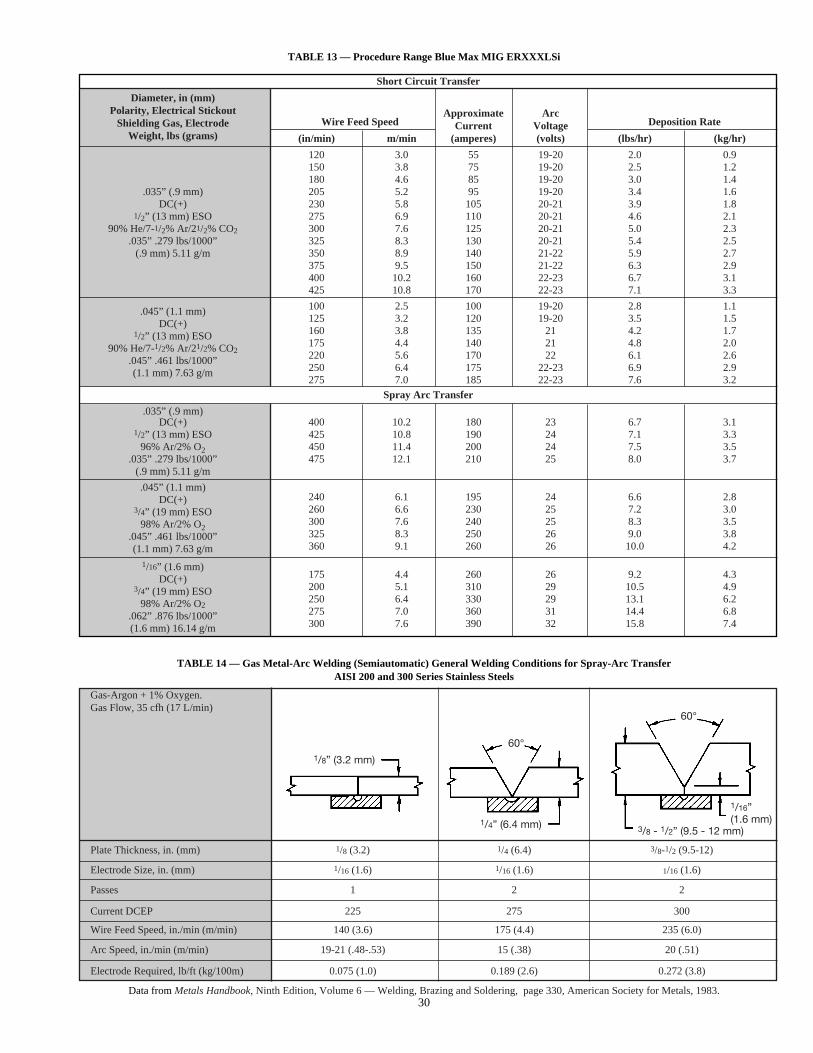
30
TABLE 13 — Procedure Range Blue Max MIG ERXXXLSi
TABLE 14 — Gas Metal-Arc Welding (Semiautomatic) General Welding Conditions for Spray-Arc TransferAISI 200 and 300 Series Stainless Steels
Data from Metals Handbook, Ninth Edition, Volume 6 — Welding, Brazing and Soldering, page 330, American Society for Metals, 1983.
Gas-Argon + 1% Oxygen.Gas Flow, 35 cfh (17 L/min)
Plate Thickness, in. (mm) 1/8 (3.2) 1/4 (6.4) 3/8-1/2 (9.5-12)
Electrode Size, in. (mm) 1/16 (1.6) 1/16 (1.6) 1/16 (1.6)
Passes 1 2 2
Current DCEP 225 275 300
Wire Feed Speed, in./min (m/min) 140 (3.6) 175 (4.4) 235 (6.0)
Arc Speed, in./min (m/min) 19-21 (.48-.53) 15 (.38) 20 (.51)
Electrode Required, lb/ft (kg/100m) 0.075 (1.0) 0.189 (2.6) 0.272 (3.8)
1/8” (3.2 mm)
60°
1/4” (6.4 mm)
60°
1/16”(1.6 mm)
3/8 - 1/2” (9.5 - 12 mm)
Short Circuit Transfer
Diameter, in (mm)Polarity, Electrical Stickout Approximate Arc
Shielding Gas, Electrode Wire Feed Speed Current Voltage Deposition RateWeight, lbs (grams) (in/min) m/min (amperes) (volts) (lbs/hr) (kg/hr)
120 3.0 55 19-20 2.0 0.9150 3.8 75 19-20 2.5 1.2180 4.6 85 19-20 3.0 1.4
.035” (.9 mm) 205 5.2 95 19-20 3.4 1.6DC(+) 230 5.8 105 20-21 3.9 1.8
1/2” (13 mm) ESO 275 6.9 110 20-21 4.6 2.190% He/7-1/2% Ar/21/2% CO2 300 7.6 125 20-21 5.0 2.3
.035” .279 lbs/1000” 325 8.3 130 20-21 5.4 2.5(.9 mm) 5.11 g/m 350 8.9 140 21-22 5.9 2.7
375 9.5 150 21-22 6.3 2.9400 10.2 160 22-23 6.7 3.1425 10.8 170 22-23 7.1 3.3
.045” (1.1 mm) 100 2.5 100 19-20 2.8 1.1
DC(+) 125 3.2 120 19-20 3.5 1.5
1/2” (13 mm) ESO 160 3.8 135 21 4.2 1.7
90% He/7-1/2% Ar/21/2% CO2175 4.4 140 21 4.8 2.0
.045” .461 lbs/1000” 220 5.6 170 22 6.1 2.6
(1.1 mm) 7.63 g/m 250 6.4 175 22-23 6.9 2.9275 7.0 185 22-23 7.6 3.2
Spray Arc Transfer
.035” (.9 mm)DC(+) 400 10.2 180 23 6.7 3.1
1/2” (13 mm) ESO 425 10.8 190 24 7.1 3.396% Ar/2% O2 450 11.4 200 24 7.5 3.5
.035” .279 lbs/1000” 475 12.1 210 25 8.0 3.7(.9 mm) 5.11 g/m
.045” (1.1 mm)DC(+) 240 6.1 195 24 6.6 2.8
3/4” (19 mm) ESO 260 6.6 230 25 7.2 3.0
98% Ar/2% O2300 7.6 240 25 8.3 3.5
.045” .461 lbs/1000” 325 8.3 250 26 9.0 3.8
(1.1 mm) 7.63 g/m 360 9.1 260 26 10.0 4.2
1/16” (1.6 mm)DC(+) 175 4.4 260 26 9.2 4.3
3/4” (19 mm) ESO 200 5.1 310 29 10.5 4.9
98% Ar/2% O2250 6.4 330 29 13.1 6.2
.062” .876 lbs/1000” 275 7.0 360 31 14.4 6.8
(1.6 mm) 16.14 g/m 300 7.6 390 32 15.8 7.4
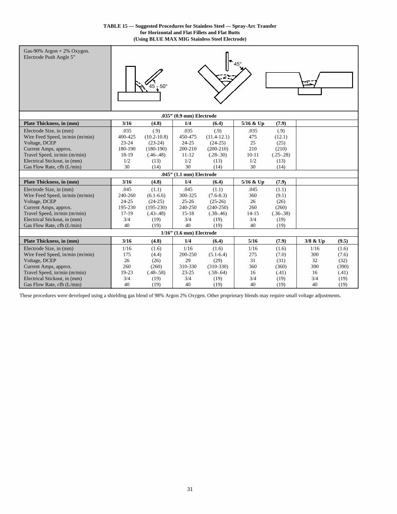
31
TABLE 15 — Suggested Procedures for Stainless Steel — Spray-Arc Transferfor Horizontal and Flat Fillets and Flat Butts
(Using BLUE MAX MIG Stainless Steel Electrode)
Gas-90% Argon + 2% Oxygen.Electrode Push Angle 5”
.035” (0.9 mm) ElectrodePlate Thickness, in (mm) 3/16 (4.8) 1/4 (6.4) 5/16 & Up (7.9)Electrode Size, in (mm) .035 (.9) .035 (.9) .035 (.9)Wire Feed Speed, in/min (m/min) 400-425 (10.2-10.8) 450-475 (11.4-12.1) 475 (12.1)Voltage, DCEP 23-24 (23-24) 24-25 (24-25) 25 (25)Current Amps, approx. 180-190 (180-190) 200-210 (200-210) 210 (210)Travel Speed, in/min (m/min) 18-19 (.46-.48) 11-12 (.28-.30) 10-11 (.25-.28)Electrical Stickout, in (mm) 1/2 (13) 1/2 (13) 1/2 (13)Gas Flow Rate, cfh (L/min) 30 (14) 30 (14) 30 (14)
.045” (1.1 mm) ElectrodePlate Thickness, in (mm) 3/16 (4.8) 1/4 (6.4) 5/16 & Up (7.9)Electrode Size, in (mm) .045 (1.1) .045 (1.1) .045 (1.1)Wire Feed Speed, in/min (m/min) 240-260 (6.1-6.6) 300-325 (7.6-8.3) 360 (9.1)Voltage, DCEP 24-25 (24-25) 25-26 (25-26) 26 (26)Current Amps, approx. 195-230 (195-230) 240-250 (240-250) 260 (260)Travel Speed, in/min (m/min) 17-19 (.43-.48) 15-18 (.38-.46) 14-15 (.36-.38)Electrical Stickout, in (mm) 3/4 (19) 3/4 (19) 3/4 (19)Gas Flow Rate, cfh (L/min) 40 (19) 40 (19) 40 (19)
1/16” (1.6 mm) Electrode
Plate Thickness, in (mm) 3/16 (4.8) 1/4 (6.4) 5/16 (7.9) 3/8 & Up (9.5)Electrode Size, in (mm) 1/16 (1.6) 1/16 (1.6) 1/16 (1.6) 1/16 (1.6)Wire Feed Speed, in/min (m/min) 175 (4.4) 200-250 (5.1-6.4) 275 (7.0) 300 (7.6)Voltage, DCEP 26 (26) 29 (29) 31 (31) 32 (32)Current Amps, approx. 260 (260) 310-330 (310-330) 360 (360) 390 (390)Travel Speed, in/min (m/min) 19-23 (.48-.58) 23-25 (.58-.64) 16 (.41) 16 (.41)Electrical Stickout, in (mm) 3/4 (19) 3/4 (19) 3/4 (19) 3/4 (19)Gas Flow Rate, cfh (L/min) 40 (19) 40 (19) 40 (19) 40 (19)
These procedures were developed using a shielding gas blend of 98% Argon 2% Oxygen. Other proprietary blends may require small voltage adjustments.
45 - 50°
45°
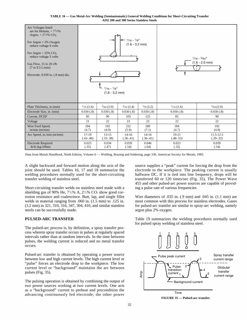
32
TABLE 16 — Gas Metal-Arc Welding (Semiautomatic) General Welding Conditions for Short-Circuiting TransferAISI 200 and 300 Series Stainless Steels
FIGURE 35 — Pulsed-arc transfer.
Arc Voltages listedare for Helium, + 71/2%Argon, + 21/2% CO2
For Argon + 2% Oxygenreduce voltage 6 volts
For Argon + 25% CO2reduce voltage 5 volts
Gas Flow, 15 to 20 cfh(7 to 9.5 L/min)
Electrode, 0.030 in. (.8 mm) dia.
Plate Thickness, in (mm) 1/16 (1.6) 5/64 (2.0) 3/32 (2.4) 1/8 (3.2) 1/16 (1.6) 5/64 (2.0)
Electrode Size, in. (min) 0.030 (.8) 0.030 (.8) 0.030 (.8) 0.030 (.8) 0.030 (.8) 0.030 (.8)
Current, DCEP 85 90 105 125 85 90
Voltage 21 22 23 23 22 22
Wire Feed Speed, 184 192 232 280 184 192in/min (m/min) (4.7) (4.9) (5.9) (7.1) (4.7) (4.9)
Arc Speed, in./min (m/mm) 17-19 13-15 14-16 14-16 19-21 11.5-12.5(.43-.48) (.33-.38) (.36-.41) (.36-.41) (.48-.53) (.29-.32)
Electrode Required 0.025 0.034 0.039 0.046 0.023 0.039lb/ft (kg/100m) (.35) (.47) (.54) (.64) (.32) (.54)
Data from Metals Handbook, Ninth Edition, Volume 6 — Welding, Brazing and Soldering, page 330, American Society for Metals, 1983.
A slight backward and forward motion along the axis of thejoint should be used. Tables 16, 17 and 18 summarize thewelding procedures normally used for the short-circuitingtransfer welding of stainless steel.
Short-circuiting transfer welds on stainless steel made with ashielding gas of 90% He, 71/2% A, 21/2% CO2 show good cor-rosion resistance and coalescence. Butt, lap, and single filletwelds in material ranging from .060 in. (1.5 mm) to .125 in.(3.2 mm) in 321, 310, 316, 347, 304, 410, and similar stainlesssteels can be successfully made.
PULSED-ARC TRANSFER
The pulsed-arc process is, by definition, a spray transfer pro-cess wherein spray transfer occurs in pulses at regularly spacedintervals rather than at random intervals. In the time betweenpulses, the welding current is reduced and no metal transferoccurs.
Pulsed-arc transfer is obtained by operating a power sourcebetween low and high current levels. The high current level or“pulse” forces an electrode drop to the workpiece. The lowcurrent level or “background” maintains the arc betweenpulses (Fig. 35).
The pulsing operation is obtained by combining the output oftwo power sources working at two current levels. One actsas a “background” current to preheat and precondition theadvancing continuously fed electrode; the other power
source supplies a “peak” current for forcing the drop from theelectrode to the workpiece. The peaking current is usuallyhalfwave DC. If it is tied into line frequency, drops will betransferred 60 or 120 times/sec (Fig. 35). The Power Wave455 and other pulsed-arc power sources are capable of provid-ing a pulse rate of various frequencies
Wire diameters of .035 in. (.9 mm) and .045 in. (1.1 mm) aremost common with this process for stainless electrodes. Gasesfor pulsed-arc transfer are similar to spray-arc welding, namelyargon plus 2% oxygen.
Table 19 summarizes the welding procedures normally usedfor pulsed spray welding of stainless steel.
1/16 - 1/8”(1.6 - 3.2 mm)
1/16 - 5/64”(1.6 - 2.0 mm)
1/16 - 1/8”(1.6 - 3.2 mm)
Pulsetransitioncurrent
1
1
2 3 4
4
5
5
Spray transfercurrent range
Globulartransfer
current range
Pulse peak current
Background current
Time
Am
p
2
3
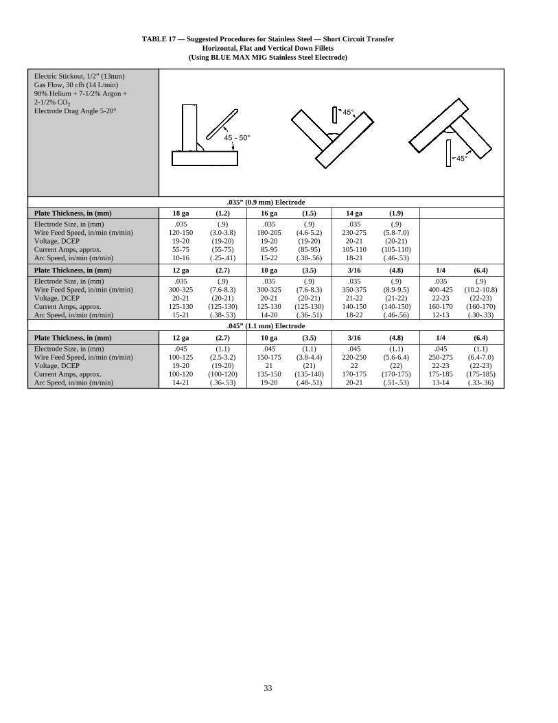
33
TABLE 17 — Suggested Procedures for Stainless Steel — Short Circuit TransferHorizontal, Flat and Vertical Down Fillets
(Using BLUE MAX MIG Stainless Steel Electrode)
Electric Stickout, 1/2” (13mm)Gas Flow, 30 cfh (14 L/min)90% Helium + 7-1/2% Argon +2-1/2% CO2Electrode Drag Angle 5-20°
.035” (0.9 mm) Electrode
Plate Thickness, in (mm) 18 ga (1.2) 16 ga (1.5) 14 ga (1.9)
Electrode Size, in (mm) .035 (.9) .035 (.9) .035 (.9)Wire Feed Speed, in/min (m/min) 120-150 (3.0-3.8) 180-205 (4.6-5.2) 230-275 (5.8-7.0)Voltage, DCEP 19-20 (19-20) 19-20 (19-20) 20-21 (20-21)Current Amps, approx. 55-75 (55-75) 85-95 (85-95) 105-110 (105-110)Arc Speed, in/min (m/min) 10-16 (.25-.41) 15-22 (.38-.56) 18-21 (.46-.53)
Plate Thickness, in (mm) 12 ga (2.7) 10 ga (3.5) 3/16 (4.8) 1/4 (6.4)
Electrode Size, in (mm) .035 (.9) .035 (.9) .035 (.9) .035 (.9)Wire Feed Speed, in/min (m/min) 300-325 (7.6-8.3) 300-325 (7.6-8.3) 350-375 (8.9-9.5) 400-425 (10.2-10.8)Voltage, DCEP 20-21 (20-21) 20-21 (20-21) 21-22 (21-22) 22-23 (22-23)Current Amps, approx. 125-130 (125-130) 125-130 (125-130) 140-150 (140-150) 160-170 (160-170)Arc Speed, in/min (m/min) 15-21 (.38-.53) 14-20 (.36-.51) 18-22 (.46-.56) 12-13 (.30-.33)
.045” (1.1 mm) Electrode
Plate Thickness, in (mm) 12 ga (2.7) 10 ga (3.5) 3/16 (4.8) 1/4 (6.4)
Electrode Size, in (mm) .045 (1.1) .045 (1.1) .045 (1.1) .045 (1.1)Wire Feed Speed, in/min (m/min) 100-125 (2.5-3.2) 150-175 (3.8-4.4) 220-250 (5.6-6.4) 250-275 (6.4-7.0)Voltage, DCEP 19-20 (19-20) 21 (21) 22 (22) 22-23 (22-23)Current Amps, approx. 100-120 (100-120) 135-150 (135-140) 170-175 (170-175) 175-185 (175-185)Arc Speed, in/min (m/min) 14-21 (.36-.53) 19-20 (.48-.51) 20-21 (.51-.53) 13-14 (.33-.36)
45 - 50°
45°
45°
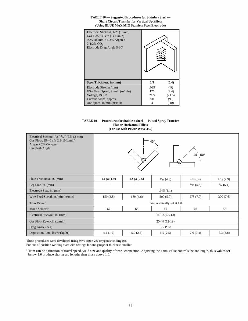
34
TABLE 18 — Suggested Procedures for Stainless Steel —Short Circuit Transfer for Vertical Up Fillets
(Using BLUE MAX MIG Stainless Steel Electrode)
Electrical Stickout, 1/2” (13mm)Gas Flow, 30 cfh (14 L/min)90% Helium 7-1/2% Argon +2-1/2% CO2Electrode Drag Angle 5-10°
Steel Thickness, in (mm) 1/4 (6.4)
Electrode Size, in (mm) .035 (.9)Wire Feed Speed, in/min (m/min) 175 (4.4)Voltage, DCEP 21.5 (21.5)Current Amps, approx. 90 (90)Arc Speed, in/min (m/min) 4 (.10)
TABLE 19 — Procedures for Stainless Steel — Pulsed Spray TransferFlat or Horizontal Fillets
(For use with Power Wave 455)
These procedures were developed using 98% argon 2% oxygen shielding gas.For out-of-position welding start with settings for one gauge or thickness smaller.
Electrical Stickout, 3/8”-1/2” (9.5-13 mm)Gas Flow, 25-40 cfh (12-19 L/min)Argon + 2% OxygenUse Push Angle
Plate Thickness, in. (mm) 14 ga (1.9) 12 ga (2.6) 3/16 (4.8) 1/4 (6.4) 5/16 (7.9)
Leg Size, in. (mm) — — — 3/16 (4.8) 1/4 (6.4)
Electrode Size, in. (mm) .045 (1.1)
Wire Feed Speed, in./min (m/min) 150 (3.8) 180 (4.6) 200 (5.0) 275 (7.0) 300 (7.6)
Trim Value1 Trim nominally set at 1.0
Mode Selector 62 63 65 66 67
Electrical Stickout, in. (mm) 3/8-1/2 (9.5-13)
Gas Flow Rate, cfh (L/min) 25-40 (12-19)
Drag Angle (deg) 0-5 Push
Deposition Rate, lbs/hr (kg/hr) 4.2 (1.9) 5.0 (2.3) 5.5 (2.5) 7.6 (3.4) 8.3 (3.8)
45°
45 - 50°
1 Trim can be a function of travel speed, weld size and quality of work connection. Adjusting the Trim Value controls the arc length, thus values setbelow 1.0 produce shorter arc lengths than those above 1.0.
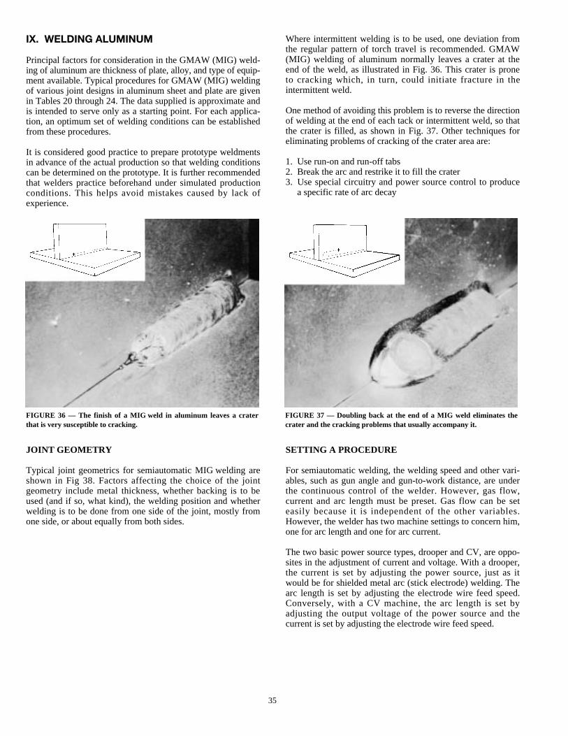
35
FIGURE 36 — The finish of a MIG weld in aluminum leaves a craterthat is very susceptible to cracking.
FIGURE 37 — Doubling back at the end of a MIG weld eliminates thecrater and the cracking problems that usually accompany it.
IX. WELDING ALUMINUM
Principal factors for consideration in the GMAW (MIG) weld-ing of aluminum are thickness of plate, alloy, and type of equip-ment available. Typical procedures for GMAW (MIG) weldingof various joint designs in aluminum sheet and plate are givenin Tables 20 through 24. The data supplied is approximate andis intended to serve only as a starting point. For each applica-tion, an optimum set of welding conditions can be establishedfrom these procedures.
It is considered good practice to prepare prototype weldmentsin advance of the actual production so that welding conditionscan be determined on the prototype. It is further recommendedthat welders practice beforehand under simulated productionconditions. This helps avoid mistakes caused by lack ofexperience.
Where intermittent welding is to be used, one deviation fromthe regular pattern of torch travel is recommended. GMAW(MIG) welding of aluminum normally leaves a crater at theend of the weld, as illustrated in Fig. 36. This crater is proneto cracking which, in turn, could initiate fracture in theintermittent weld.
One method of avoiding this problem is to reverse the directionof welding at the end of each tack or intermittent weld, so thatthe crater is filled, as shown in Fig. 37. Other techniques foreliminating problems of cracking of the crater area are:
1. Use run-on and run-off tabs2. Break the arc and restrike it to fill the crater3. Use special circuitry and power source control to produce
a specific rate of arc decay
JOINT GEOMETRY
Typical joint geometrics for semiautomatic MIG welding areshown in Fig 38. Factors affecting the choice of the jointgeometry include metal thickness, whether backing is to beused (and if so, what kind), the welding position and whetherwelding is to be done from one side of the joint, mostly fromone side, or about equally from both sides.
SETTING A PROCEDURE
For semiautomatic welding, the welding speed and other vari-ables, such as gun angle and gun-to-work distance, are underthe continuous control of the welder. However, gas flow,current and arc length must be preset. Gas flow can be seteasily because it is independent of the other variables.However, the welder has two machine settings to concern him,one for arc length and one for arc current.
The two basic power source types, drooper and CV, are oppo-sites in the adjustment of current and voltage. With a drooper,the current is set by adjusting the power source, just as itwould be for shielded metal arc (stick electrode) welding. Thearc length is set by adjusting the electrode wire feed speed.Conversely, with a CV machine, the arc length is set byadjusting the output voltage of the power source and thecurrent is set by adjusting the electrode wire feed speed.
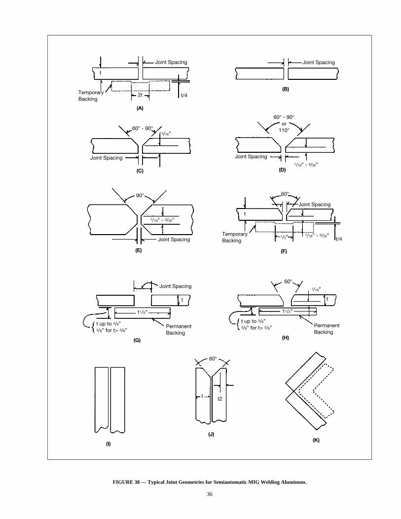
36
FIGURE 38 — Typical Joint Geometries for Semiautomatic MIG Welding Aluminum.
Joint Spacing
TemporaryBacking
t
2t
(A)
Joint Spacing
(B)
Joint Spacing1/16” - 3/32”
60° - 90°or
110°
(D)
Joint Spacing
3/16”60° - 90°
(C)
Joint Spacing
1/16” - 3/32”
90°
(E)
Joint Spacing
1/16” - 3/32”t/4
1/2”
t
TemporaryBacking
60°
(F)
Joint Spacing
t up to 3/8”3/8” for t> 3/8”
11/2”
t
PermanentBacking
(G)
t up to 3/8”3/8” for t> 3/8”
11/2”
1/16”
60°
t
PermanentBacking
(H)
60°
t t2
(I)
(J)(K)
t/4
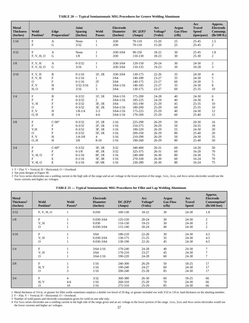
37
TABLE 20 — Typical Semiautomatic MIG Procedures for Groove Welding Aluminum
TABLE 21 — Typical Semiautomatic MIG Procedures for Fillet and Lap Welding Aluminum
Approx.Metal Electrode Arc Argon Arc ElectrodeThickness1 Weld Weld Diameter DC (EP)4 Voltage4 Gas Flow Travel Consumption3(Inches) Position2 Passes3 (Inches) (Amps) (Volts) (cfh) Speed (lb/100 feet)
3/32 F, V, H, O 1 0.030 100-130 18-22 30 24-30 1.8
1/8 F 1 0.030-3/64 125-150 20-24 30 24-30 2V, H 1 0.030 110-130 19-23 30 24-30 2O 1 0.030-3/64 115-140 20-24 40 24-30 2
3/16 F 1 3/64 180-210 22-26 30 24-30 4.5V, H 1 0.030-3/64 130-175 21-25 35 24-30 4.5O 1 0.030-3/64 130-190 22-26 45 24-30 4.5
1/4 F 1 3/64-1/16 170-240 24-28 40 24-30 7V, H 1 3/64 170-210 23-27 45 24-30 7O 1 3/64-1/16 190-220 24-28 60 24-30 7
3/8 F 1 1/16 240-300 26-29 50 18-25 17H, V 3 1/16 190-240 24-27 60 24-30 17O 3 1/16 200-240 25-28 85 24-30 17
3/4 F 4 3/32 360-380 26-30 60 18-25 66H, V 4-6 1/16 260-310 25-29 70 24-30 66O 10 1/16 275-310 25-29 85 24-30 66
1 Metal thickness of 3/4 in. or greater for fillet welds sometimes employs a double vee bevel of 50 deg. or greater included vee with 3/32 to 1/8 in. land thickness on the abutting member.2 F = Flat; V = Vertical; H = Horizontal; O = Overhead.3 Number of weld passes and electrode consumption given for weld on one side only.4 For 5xxx series electrodes use a welding current in the high side of the range given and an arc voltage in the lower portion of the range. 1xxx, 2xxx and 4xxx series electrodes would use
the lower currents and higher arc voltages.
Arc Approx.Metal Joint Electrode Arc Argon Travel ElectrodeThickness Weld Edge Spacing Weld Diameter DC (EP)3 Voltage3 Gas Flow Speed Consump.(Inches) Position1 Preparation2 (Inches) Passes (Inches) (Amps) (Volts) (cfh) (ipm/pass) (lb/100 ft.)
1/16 F A None 1 .030 70-110 15-20 25 25-45 1.5F G 3/32 1 .030 70-110 15-20 25 25-45 2
3/32 F A None 1 .030-3/64 90-150 18-22 30 25-45 1.8F, V, H, O G 1/8 1 .030 110-130 18-23 30 25-30 2
1/8 F, V, H A 0-3/32 1 .030-3/64 120-150 20-24 30 24-30 2F, V, H, O G 3/16 1 .030-3/64 110-135 19-23 30 18-28 3
3/16 F, V, H B 0-1/16 1F, 1R .030-3/64 130-175 22-26 35 24-30 4F, V, H F 0-1/16 1 3/64 140-180 23-27 35 24-30 5O F 0-1/16 2F 3/64 140-175 23-27 60 24-30 5F, V H 3/32-3/16 2 3/64-1/16 140-185 23-27 35 24-30 8H, O H 3/16 3 3/64 130-175 23-27 60 25-35 10
1/4 F B 0-3/32 1F, 1R 3/64-1/16 175-200 24-28 40 24-30 6F F 0-3/32 2 3/64-1/16 185-225 24-29 40 24-30 8V, H F 0-3/32 3F, 1R 3/64 165-190 25-29 45 25-35 10O F 0-3/32 3F, 1R 3/64-1/16 180-200 25-29 60 25-35 10F, V H 1/8-1/4 2-3 3/64-1/16 175-225 25-29 40 24-30 12O, H H 1/4 4-6 3/64-1/16 170-200 25-29 60 25-40 12
3/8 F C-90° 0-3/32 1F, 1R 1/16 225-290 26-29 50 20-30 16F F 0-3/32 2F, 1R 1/16 210-275 26-29 50 24-35 18V,H F 0-3/32 3F, 1R 1/16 190-220 26-29 55 24-30 20O F 0-3/32 5F, 1R 1/16 200-250 26-29 80 25-40 20F, V H 1/4-3/8 4 1/16 210-290 26-29 50 24-30 35O, H H 3/8 8-10 1/16 190-260 26-29 80 25-40 50
3/4 F C-60° 0-3/32 3F, 1R 3/32 340-400 26-31 60 14-20 50F F 0-1/8 4F, 1R 3/32 325-375 26-31 60 16-20 70V, H, O F 0-1/16 8F, 1R 1/16 240-300 26-30 80 24-30 75F E 0-1/16 3F, 3R 1/16 270-330 26-30 60 16-24 70V, H, O E 0-1/16 6F, 6R 1/16 230-280 26-30 80 16-24 75
1 F = Flat; V = Vertical; H = Horizontal; O = Overhead.2 See joint designs in Figure 38.3 For 5xxx series electrodes use a welding current in the high side of the range and an arc voltage in the lower portion of the range. 1xxx, 2xxx, and 4xxx series electrodes would use the
lower currents and higher arc voltages.
38
X. SAFE PRACTICES
Introduction. The general subject of safety and safety practicesin welding, cutting, and allied processes is covered in ANSIZ49.18, “Safety in Welding and Cutting,” and ANSI Z49.29.“Fire Prevention in the Use of Welding and CuttingProcesses.” The handling of compressed gases is covered inCGA P-110.
Personnel should be familiar with the safe practices discussedin these documents, equipment operating manuals, andMaterial Safety Data Sheets (MSDS) for consumables.
In addition to the hazards discussed in the Arc Welding SafetyPrecautions following this section, be familiar with the safetyconcerns discussed below.
Safe Handling of Shielding Gas Cylinders and Regulators.Compressed gas cylinders should be handled carefully andshould be adequately secured when in use. Knocks, falls, orrough handling may damage cylinders, valves, or fuse plugsand cause leakage or accident. Valve protecting caps, whensupplied, should be kept in place (handtight) until theconnecting of container equipment.
Cylinder Use.The following should be observed when settingup and using cylinders of shielding gas:
1. Properly secure the cylinder.2. Before connecting a regulator to the cylinder valve, the
valve should momentarily be slightly opened and closedimmediately (opening) to clear the valve of dust or dirt thatotherwise might enter the regulator. The valve operatorshould stand to one side of the regulator gauges, never infront of them.
3. After the regulator is attached, the adjusting screw shouldbe released by turning it counter-clockwise. The cylindervalve should then be opened slowly to prevent a too-rapidsurge of high pressure gas into the regulator.
4. The source of the gas supply (i.e., the cylinder valve) shouldbe shut off if it is to be left unattended.
Gases.The major toxic gases associated with GMAW weldingare ozone, nitrogen dioxide, and carbon monoxide. Phosgenegas could also be present as a result of thermal or ultravioletdecomposition of chlorinated hydrocarbon cleaning agents lo-cated in the vicinity of welding operations, such as trichlor-ethylene and perchlorethylene. DEGREASING OR OTHERCLEANING OPERATIONS INVOLVING CHLORINATEDHYDROCARBONS SHOULD BE SO LOCATED THAT VA-PORS FROM THESE OPERATIONS CANNOT BEREACHED BY RADIATION FROM THE WELDING ARC.
Ozone.The ultraviolet light emitted by the GMAW arc actson the oxygen in the surrounding atmosphere to produceozone, the amount of which will depend upon the intensityand the wave length of the ultraviolet energy, the humidity,the amount of screening afforded by any welding fumes, andother factors. The ozone concentration will generally be in-creased with an increase in welding current, with the use ofargon as the shielding gas, and when welding highly reflectivemetals. If the ozone cannot be reduced to a safe level by ven-tilation or process variations, it will be necessary to supplyfresh air to the welder either with an air supplied respirator orby other means.
Nitrogen Dioxide. Some test results show that high concentra-tions of nitrogen dioxide are found only within 6 in. (152 mm)of the arc. With normal natural ventilation, these concentra-tions are quickly reduced to safe levels in the welder’s breathingzone, so long as the welder keeps his head out of the plume offumes (and thus out of the plume of welding-generated gases).Nitrogen dioxide is not thought to be a hazard in GMAW.
Carbon Monoxide. Carbon dioxide shielding used with theGMAW process will be dissociated by the heat of the arc toform carbon monoxide. Only a small amount of carbon mon-oxide is created by the welding process, although relatively highconcentrations are formed temporarily in the plume of fumes.However, the hot carbon monoxide oxidizes to carbon dioxideso that the concentrations of carbon monoxide become insig-nificant at distances of more than 3 or 4 in. (76 or 102 mm)from the welding plume.
Under normal welding conditions there should be no hazardfrom this source. When the welder must work with his headover the welding arc, or with the natural ventilation movingthe plume of fumes towards his breathing zone, or where weld-ing is performed in a confined space, ventilation adequate todeflect the plume or remove the fumes and gases must beprovided. Because shielding gases can displace air, use specialcare to insure that breathing air is safe when welding in a con-fined space. (See ANSI Z49.1.)
Metal Fumes.The welding fumes generated by GMAW can becontrolled by general ventilation, local exhaust ventilation, orby respiratory protective equipment as described in ANSIZ49.1. The method of ventilation required to keep the levelof toxic substances within the welder’s breathing zone belowacceptable concentrations is directly dependent upon a numberof factors. Among these are the material being welded, thesize of the work area, and the degree of the confinement orobstruction to normal air movement where the welding is beingdone. Each operation should be evaluated on an individualbasis in order to determine what will be required. Acceptablelevels of toxic substances associated with welding, and desig-nated as time-weighted average threshold limit values (TLV)and ceiling val-ues, have been established by the AmericanConference of Governmental Industrial Hygienists (ACGIH)and by the Occupational Safety and Health Administration(OSHA). Compliance with these acceptable levels can bechecked by sampling the atmosphere under the welder’s hel-met or in the immediate vicinity of the helper’s breathingzone. The principle composition or particulate matter (weldingfume) which may be present within the welder’s breathingzone are listed in Table 22. Sampling should be in accordancewith ANSI/ AWS F1.1, Method for Sampling AirborneParticulates Generated by Welding and Allied Processes.
8 ANSI Z49.1 is available from the American Welding Society, 550N.W. LeJeune Road, Miami, Florida 33126.
9 ANSI Z49.2 is available from the American National StandardsInstitute, 11 West 42nd Street, New York, NY 10036.
10 CGA P-1 is available from the Compressed Gas Association, Inc.,1235 Jefferson Davis Highway, Suite 501, Arlington, VA 22202.
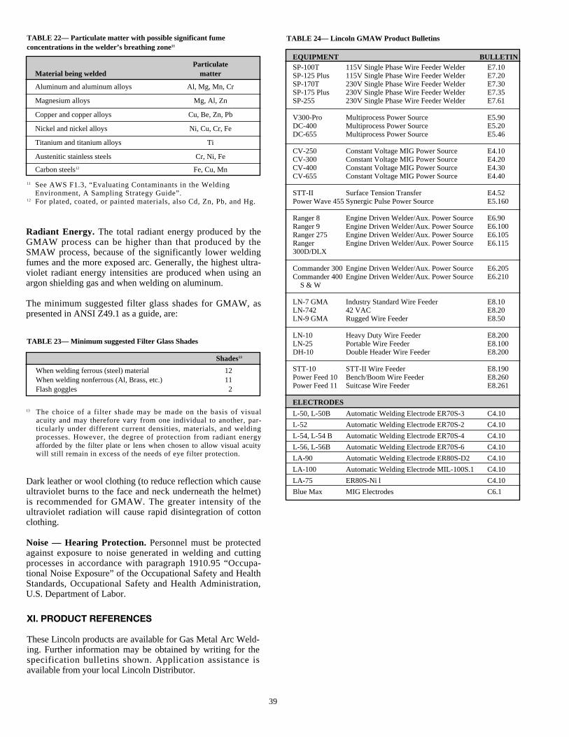
39
Radiant Energy. The total radiant energy produced by theGMAW process can be higher than that produced by theSMAW process, because of the significantly lower weldingfumes and the more exposed arc. Generally, the highest ultra-violet radiant energy intensities are produced when using anargon shielding gas and when welding on aluminum.
The minimum suggested filter glass shades for GMAW, aspresented in ANSI Z49.1 as a guide, are:
XI. PRODUCT REFERENCES
These Lincoln products are available for Gas Metal Arc Weld-ing. Further information may be obtained by writing for thespecification bulletins shown. Application assistance isavailable from your local Lincoln Distributor.
TABLE 22— Particulate matter with possible significant fume concentrations in the welder’s breathing zone11
TABLE 24— Lincoln GMAW Product Bulletins
TABLE 23— Minimum suggested Filter Glass Shades
ParticulateMaterial being welded matter
Aluminum and aluminum alloys Al, Mg, Mn, Cr
Magnesium alloys Mg, Al, Zn
Copper and copper alloys Cu, Be, Zn, Pb
Nickel and nickel alloys Ni, Cu, Cr, Fe
Titanium and titanium alloys Ti
Austenitic stainless steels Cr, Ni, Fe
Carbon steels12 Fe, Cu, Mn
11 See AWS F1.3, “Evaluating Contaminants in the WeldingEnvironment, A Sampling Strategy Guide”.
12 For plated, coated, or painted materials, also Cd, Zn, Pb, and Hg.
Shades13
When welding ferrous (steel) material 12When welding nonferrous (Al, Brass, etc.) 11Flash goggles 2
13 The choice of a filter shade may be made on the basis of visualacuity and may therefore vary from one individual to another, par-ticularly under different current densities, materials, and weldingprocesses. However, the degree of protection from radiant energyafforded by the filter plate or lens when chosen to allow visual acuitywill still remain in excess of the needs of eye filter protection.
Dark leather or wool clothing (to reduce reflection which causeultraviolet burns to the face and neck underneath the helmet)is recommended for GMAW. The greater intensity of theultraviolet radiation will cause rapid disintegration of cottonclothing.
Noise — Hearing Protection.Personnel must be protectedagainst exposure to noise generated in welding and cuttingprocesses in accordance with paragraph 1910.95 “Occupa-tional Noise Exposure” of the Occupational Safety and HealthStandards, Occupational Safety and Health Administration,U.S. Department of Labor.
EQUIPMENT BULLETINSP-100T 115V Single Phase Wire Feeder Welder E7.10SP-125 Plus 115V Single Phase Wire Feeder Welder E7.20SP-170T 230V Single Phase Wire Feeder Welder E7.30SP-175 Plus 230V Single Phase Wire Feeder Welder E7.35SP-255 230V Single Phase Wire Feeder Welder E7.61
V300-Pro Multiprocess Power Source E5.90DC-400 Multiprocess Power Source E5.20DC-655 Multiprocess Power Source E5.46
CV-250 Constant Voltage MIG Power Source E4.10CV-300 Constant Voltage MIG Power Source E4.20CV-400 Constant Voltage MIG Power Source E4.30CV-655 Constant Voltage MIG Power Source E4.40
STT-II Surface Tension Transfer E4.52Power Wave 455 Synergic Pulse Power Source E5.160
Ranger 8 Engine Driven Welder/Aux. Power Source E6.90Ranger 9 Engine Driven Welder/Aux. Power Source E6.100Ranger 275 Engine Driven Welder/Aux. Power Source E6.105Ranger Engine Driven Welder/Aux. Power Source E6.115300D/DLX
Commander 300 Engine Driven Welder/Aux. Power Source E6.205Commander 400 Engine Driven Welder/Aux. Power Source E6.210
S & W
LN-7 GMA Industry Standard Wire Feeder E8.10LN-742 42 VAC E8.20LN-9 GMA Rugged Wire Feeder E8.50
LN-10 Heavy Duty Wire Feeder E8.200LN-25 Portable Wire Feeder E8.100DH-10 Double Header Wire Feeder E8.200
STT-10 STT-II Wire Feeder E8.190Power Feed 10 Bench/Boom Wire Feeder E8.260Power Feed 11 Suitcase Wire Feeder E8.261
ELECTRODES
L-50, L-50B Automatic Welding Electrode ER70S-3 C4.10
L-52 Automatic Welding Electrode ER70S-2 C4.10
L-54, L-54 B Automatic Welding Electrode ER70S-4 C4.10
L-56, L-56B Automatic Welding Electrode ER70S-6 C4.10
LA-90 Automatic Welding Electrode ER80S-D2 C4.10
LA-100 Automatic Welding Electrode MIL-100S.1 C4.10
LA-75 ER80S-Ni l C4.10
Blue Max MIG Electrodes C6.1
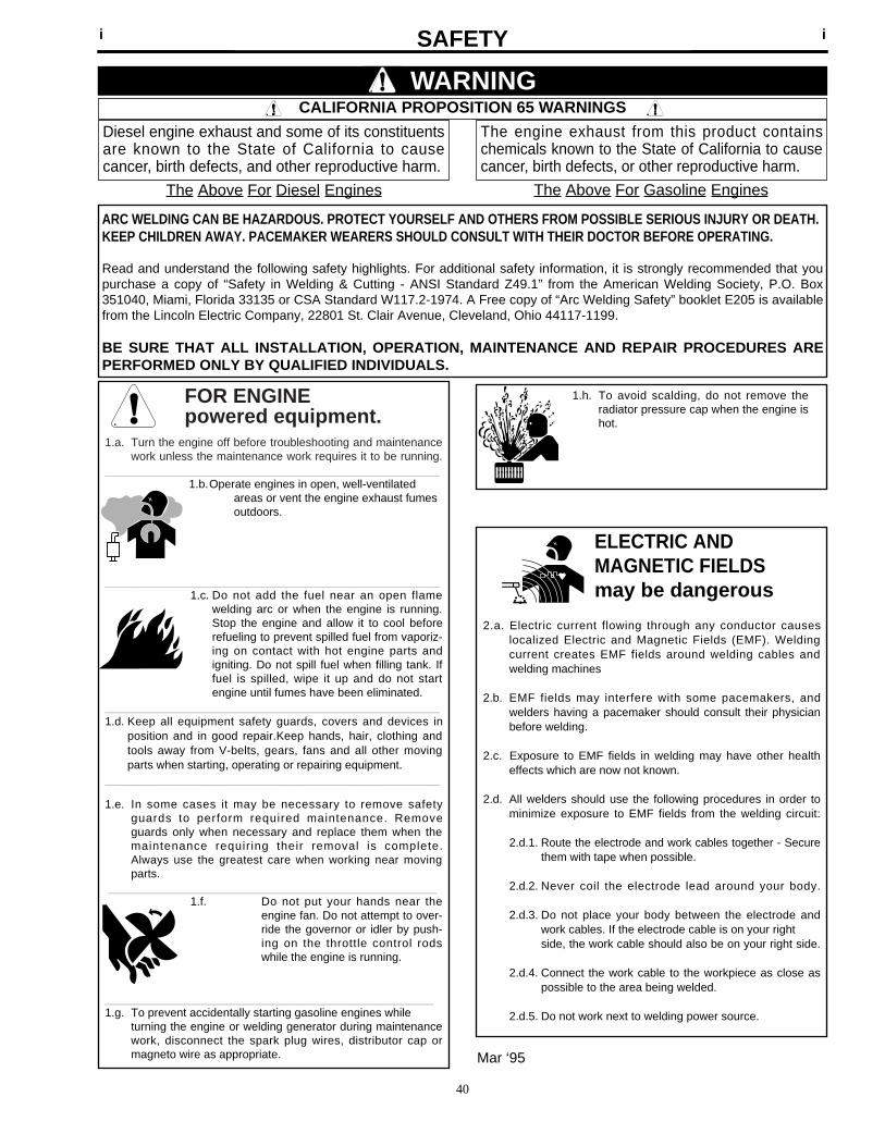
FOR ENGINEpowered equipment.
1.a. Turn the engine off before troubleshooting and maintenancework unless the maintenance work requires it to be running.
____________________________________________________1.b.Operate engines in open, well-ventilated
areas or vent the engine exhaust fumes outdoors.
____________________________________________________1.c. Do not add the fuel near an open flame
welding arc or when the engine is running.Stop the engine and allow it to cool beforerefueling to prevent spilled fuel from vaporiz-ing on contact with hot engine parts andigniting. Do not spill fuel when filling tank. Iffuel is spilled, wipe it up and do not startengine until fumes have been eliminated.
____________________________________________________1.d. Keep all equipment safety guards, covers and devices in
position and in good repair.Keep hands, hair, clothing andtools away from V-belts, gears, fans and all other movingparts when starting, operating or repairing equipment.
____________________________________________________
1.e. In some cases it may be necessary to remove safetyguards to perform required maintenance. Removeguards only when necessary and replace them when themaintenance requiring their removal is complete.Always use the greatest care when working near movingparts.
___________________________________________________1.f. Do not put your hands near the
engine fan. Do not attempt to over-ride the governor or idler by push-ing on the throttle control rodswhile the engine is running.
___________________________________________________1.g. To prevent accidentally starting gasoline engines while
turning the engine or welding generator during maintenancework, disconnect the spark plug wires, distributor cap ormagneto wire as appropriate.
iSAFETYi
ARC WELDING CAN BE HAZARDOUS. PROTECT YOURSELF AND OTHERS FROM POSSIBLE SERIOUS INJURY OR DEATH.KEEP CHILDREN AWAY. PACEMAKER WEARERS SHOULD CONSULT WITH THEIR DOCTOR BEFORE OPERATING.
Read and understand the following safety highlights. For additional safety information, it is strongly recommended that youpurchase a copy of “Safety in Welding & Cutting - ANSI Standard Z49.1” from the American Welding Society, P.O. Box351040, Miami, Florida 33135 or CSA Standard W117.2-1974. A Free copy of “Arc Welding Safety” booklet E205 is availablefrom the Lincoln Electric Company, 22801 St. Clair Avenue, Cleveland, Ohio 44117-1199.
BE SURE THAT ALL INSTALLATION, OPERATION, MAINTENANCE AND REPAIR PROCEDURES AREPERFORMED ONLY BY QUALIFIED INDIVIDUALS.
WARNING
Mar ‘95
ELECTRIC AND MAGNETIC FIELDSmay be dangerous
2.a. Electric current flowing through any conductor causes localized Electric and Magnetic Fields (EMF). Welding current creates EMF fields around welding cables and welding machines
2.b. EMF fields may interfere with some pacemakers, andwelders having a pacemaker should consult their physicianbefore welding.
2.c. Exposure to EMF fields in welding may have other healtheffects which are now not known.
2.d. All welders should use the following procedures in order tominimize exposure to EMF fields from the welding circuit:
2.d.1. Route the electrode and work cables together - Securethem with tape when possible.
2.d.2. Never coil the electrode lead around your body.
2.d.3. Do not place your body between the electrode andwork cables. If the electrode cable is on your right side, the work cable should also be on your right side.
2.d.4. Connect the work cable to the workpiece as close aspossible to the area being welded.
2.d.5. Do not work next to welding power source.
1.h. To avoid scalding, do not remove theradiator pressure cap when the engine ishot.
CALIFORNIA PROPOSITION 65 WARNINGS
Diesel engine exhaust and some of its constituentsare known to the State of California to causecancer, birth defects, and other reproductive harm.
The engine exhaust from this product containschemicals known to the State of California to causecancer, birth defects, or other reproductive harm.
The Above For Diesel Engines The Above For Gasoline Engines
40
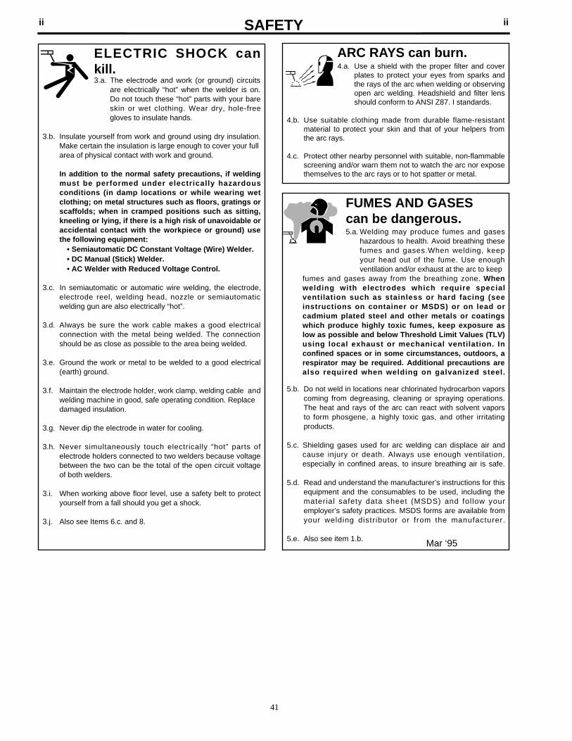
iiSAFETYii
ARC RAYS can burn.4.a. Use a shield with the proper filter and cover
plates to protect your eyes from sparks andthe rays of the arc when welding or observingopen arc welding. Headshield and filter lensshould conform to ANSI Z87. I standards.
4.b. Use suitable clothing made from durable flame-resistantmaterial to protect your skin and that of your helpers fromthe arc rays.
4.c. Protect other nearby personnel with suitable, non-flammablescreening and/or warn them not to watch the arc nor exposethemselves to the arc rays or to hot spatter or metal.
ELECTRIC SHOCK cankill.3.a. The electrode and work (or ground) circuits
are electrically “hot” when the welder is on.Do not touch these “hot” parts with your bareskin or wet clothing. Wear dry, hole-freegloves to insulate hands.
3.b. Insulate yourself from work and ground using dry insulation.Make certain the insulation is large enough to cover your fullarea of physical contact with work and ground.
In addition to the normal safety precautions, if weldingmust be performed under electrically hazardousconditions (in damp locations or while wearing wetclothing; on metal structures such as floors, gratings orscaffolds; when in cramped positions such as sitting,kneeling or lying, if there is a high risk of unavoidable oraccidental contact with the workpiece or ground) usethe following equipment:
• Semiautomatic DC Constant Voltage (Wire) Welder.• DC Manual (Stick) Welder.• AC Welder with Reduced Voltage Control.
3.c. In semiautomatic or automatic wire welding, the electrode,electrode reel, welding head, nozzle or semiautomaticwelding gun are also electrically “hot”.
3.d. Always be sure the work cable makes a good electricalconnection with the metal being welded. The connectionshould be as close as possible to the area being welded.
3.e. Ground the work or metal to be welded to a good electrical(earth) ground.
3.f. Maintain the electrode holder, work clamp, welding cable andwelding machine in good, safe operating condition. Replacedamaged insulation.
3.g. Never dip the electrode in water for cooling.
3.h. Never simultaneously touch electrically “hot” parts ofelectrode holders connected to two welders because voltagebetween the two can be the total of the open circuit voltageof both welders.
3.i. When working above floor level, use a safety belt to protectyourself from a fall should you get a shock.
3.j. Also see Items 6.c. and 8.
FUMES AND GASEScan be dangerous.5.a. Welding may produce fumes and gases
hazardous to health. Avoid breathing thesefumes and gases.When welding, keepyour head out of the fume. Use enoughventilation and/or exhaust at the arc to keep
fumes and gases away from the breathing zone. Whenwelding with electrodes which require specialventi lation such as stainless or hard facing (seeinstructions on container or MSDS) or on lead orcadmium plated steel and other metals or coatingswhich produce highly toxic fumes, keep exposure aslow as possible and below Threshold Limit Values (TLV)using local exhaust or mechanical ventilation. Inconfined spaces or in some circumstances, outdoors, arespirator may be required. Additional precautions arealso required when welding on galvanized steel.
5.b. Do not weld in locations near chlorinated hydrocarbon vaporscoming from degreasing, cleaning or spraying operations.The heat and rays of the arc can react with solvent vaporsto form phosgene, a highly toxic gas, and other irritatingproducts.
5.c. Shielding gases used for arc welding can displace air andcause injury or death. Always use enough ventilation,especially in confined areas, to insure breathing air is safe.
5.d. Read and understand the manufacturer’s instructions for thisequipment and the consumables to be used, including thematerial safety data sheet (MSDS) and fol low youremployer’s safety practices. MSDS forms are available fromyour welding distributor or from the manufacturer.
5.e. Also see item 1.b. Mar ‘95
41
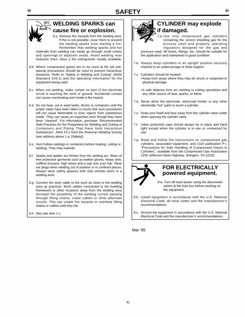
FOR ELECTRICALLYpowered equipment.
8.a. Turn off input power using the disconnectswitch at the fuse box before working onthe equipment.
8.b. Install equipment in accordance with the U.S. NationalElectrical Code, all local codes and the manufacturer’srecommendations.
8.c. Ground the equipment in accordance with the U.S. NationalElectrical Code and the manufacturer’s recommendations.
CYLINDER may explodeif damaged.7.a. Use only compressed gas cylinders
containing the correct shielding gas for theprocess used and properly operatingregulators designed for the gas and
pressure used. All hoses, fittings, etc. should be suitable forthe application and maintained in good condition.
7.b. Always keep cylinders in an upright position securelychained to an undercarriage or fixed support.
7.c. Cylinders should be located:• Away from areas where they may be struck or subjected tophysical damage.
• A safe distance from arc welding or cutting operations andany other source of heat, sparks, or flame.
7.d. Never allow the electrode, electrode holder or any otherelectrically “hot” parts to touch a cylinder.
7.e. Keep your head and face away from the cylinder valve outletwhen opening the cylinder valve.
7.f. Valve protection caps should always be in place and handtight except when the cylinder is in use or connected foruse.
7.g. Read and follow the instructions on compressed gascylinders, associated equipment, and CGA publication P-l,“Precautions for Safe Handling of Compressed Gases inCylinders,” available from the Compressed Gas Association1235 Jefferson Davis Highway, Arlington, VA 22202.
iiiSAFETYiii
Mar ‘95
WELDING SPARKS cancause fire or explosion.6.a. Remove fire hazards from the welding area.
If this is not possible, cover them to preventthe welding sparks from starting a fire.Remember that welding sparks and hot
materials from welding can easily go through small cracksand openings to adjacent areas. Avoid welding nearhydraulic lines. Have a fire extinguisher readily available.
6.b. Where compressed gases are to be used at the job site,special precautions should be used to prevent hazardoussituations. Refer to “Safety in Welding and Cutting” (ANSIStandard Z49.1) and the operating information for theequipment being used.
6.c. When not welding, make certain no part of the electrodecircuit is touching the work or ground. Accidental contactcan cause overheating and create a fire hazard.
6.d. Do not heat, cut or weld tanks, drums or containers until theproper steps have been taken to insure that such procedureswill not cause flammable or toxic vapors from substancesinside. They can cause an explosion even though they havebeen “cleaned”. For information, purchase “RecommendedSafe Practices for the Preparation for Welding and Cutting ofContainers and Piping That Have Held HazardousSubstances”, AWS F4.1 from the American Welding Society(see address above 1.a. [Safety]).
6.e. Vent hollow castings or containers before heating, cutting orwelding. They may explode.
6.f. Sparks and spatter are thrown from the welding arc. Wear oilfree protective garments such as leather gloves, heavy shirt,cuffless trousers, high shoes and a cap over your hair. Wearear plugs when welding out of position or in confined places.Always wear safety glasses with side shields when in awelding area.
6.g. Connect the work cable to the work as close to the weldingarea as practical. Work cables connected to the buildingframework or other locations away from the welding areaincrease the possibility of the welding current passingthrough lifting chains, crane cables or other alternatecircuits. This can create fire hazards or overheat liftingchains or cables until they fail.
6.h. Also see item 1.c.
42

THELINCOLN ELECTRIC
COMPANY
Local Sales and Service through GlobalSubsidiaries and Distributors
Cleveland, Ohio 44117-1199 U.S.ATEL: 216.481.8100FAX: 216.486.1751
WEB SITE: www.lincolnelectric.com
MIGC4.200 9/98
LINCOLNELECTRIC
®
LINCOLN NORTH AMERICADISTRICT OFFICE AND SALES AGENT LOCATIONS
USAALABAMA
BIRMINGHAM 35124-1156 (205) 988-8232 MOBILE 36693-4310 (334) 666-6524
ALASKAContact SEATTLE District Office(206) 575-2456
ARIZONAPHOENIX 85260-1768(602) 348-2004
ARKANSASLITTLE ROCK 72116-7034(501) 771-4842
CALIFORNIAFRESNO 93722-3949(209) 276-0110LOS ANGELES 90670-2936(562) 906-7700SACRAMENTO 95677-4729(916) 630-1885SAN DIEGO 92108-3911(619) 208-9001SAN FRANCISCO 94550-9657(925) 443-9353
COLORADODENVER 80112-5115(303) 792-2418
CONNECTICUTNORTH HAVEN 06238(860) 742-8887
WASHINGTON DCHERNDON, VA 20170-5227(703) 904-7735
FLORIDAJACKSONVILLE 32259-4396(904) 287-9595MIAMI 33014-6719(305) 556-0142TAMPA 33619-4480(770) 475-0955
GEORGIAATLANTA 30076-4914(770) 475-0955SAVANNAH 31401-5140(912) 231-9604
HAWAIISee SEATTLEDistrict Office(206) 575-2456
ILLINOISCHICAGO 60521-5629(630) 920-1500PEORIA 61607-2046(309) 697-8240
INDIANAEVANSVILLE 47710-4514(812) 428-3225FT. WAYNE 46825-5547(219) 484-4422SOUTH BEND 46530-0577(219) 277-8619INDIANAPOLIS 46038-9459(317) 845-8445
IOWACEDAR RAPIDS 52402-3160(319) 362-6804MOLINE, ILL 52806-1344(319) 386-6522DES MOINES 50265-6218 (515) 224-4121
KANSASKANSAS CITY 66214-1625(913) 894-0888WICHITA 67037(316) 788-7352
KENTUCKYLOUISVILLE 40203-2906(502) 636-5125
LOUISIANABATON ROUGE 70809-2256(504) 922-5151SHREVEPORT 71108-2521(318) 869-3531
MARYLANDBALTIMORE 21045-2565(410) 720-5232
MASSACHUSETTSBOSTON 02154-8414(781) 899-2010
MICHIGANDETROIT 48034-4005(248) 353-9680FLUSHING 48433-1855(810) 487-1310GRAND RAPIDS 49512-3924(616) 942-8780
MINNESOTAMINNEAPOLIS 55447-5435(612) 551-1990
MISSISSIPPIJACKSON 39212-9635(601) 372-7679
MISSOURIKANSAS CITY (KS) 66214-1625(913) 894-0888ST. LOUIS 63146-3572(314) 993-5465
MONTANAContact SEATTLEDistrict Office(206) 575-2456
NEBRASKAOMAHA 68046-2826(402) 339-1809
NEW JERSEYEDISON 08837-3939(732) 225-2000LEBANON 08833-0700(888) 427-2269
NEW MEXICOALBUQUERQUE 87111-2158(505) 237-2433
NEW YORKALBANY 12205-5427(518) 482-3389BUFFALO 14225-5515(716) 681-5554NEW YORK CITY (888) 269-6755EAST SYRACUSE 13057-1040(315) 432-0281
NORTH CAROLINACHARLOTTE 28273-6200(704) 588-3251RALEIGH 27604-8456(919) 231-5855
OHIOCINCINNATI 45215-1187(513) 772-1440CLEVELAND 44143-1433(216) 289-4160COLUMBUS 43221-4073(614) 488-7913DAYTON 45439-1254(937) 299-9506TOLEDO 43528-9483(419) 867-7284
OKLAHOMAOKLAHOMA CITY 73119-2416(405) 686-1170TULSA 74146-1622(918) 622-9353
OREGONPORTLAND 97230-1030(503) 252-8835
PENNSYLVANIABETHLEHEM 18020-2062(610) 866-8788ERIE 16506-2979(814) 835-3531JOHNSTOWN 15905-2506(814) 535-5895PHILADELPHIA 19008-4310(610) 543-9462PITTSBURGH 15275-1002(412) 787-7733YORK 17404-1144(717) 764-6565
SOUTH CAROLINAFLORENCE 29505-3615(803) 673-0830GREENVILLE 29612-0126(864) 967-4157
SOUTH DAKOTASIOUX FALLS 57108-2609(605) 339-6522
TENNESSEEKNOXVILLE 37923-4506(423) 693-5513MEMPHIS 38115-5946(901) 363-1075NASHVILLE 37210-3816(615) 316-9777TRI-CITIES 37604-3338(423) 928-6047
TEXASCONROE 77304-1524(409) 588-1116DALLAS 76051-7602(817) 329-9353HOUSTON 77060-3143(281) 847-9444SAN ANTONIO 78133-3502(830) 964-2421
UTAHMIDVALE 84047-3759(801) 233-9353
VIRGINIAHERNDON 20170-5227Washington, D.C.(703) 904-7735ROANOKE 24153-1447(540) 389-4032WILLIAMSBURG 23602-7048(757) 881-9762
WASHINGTONSEATTLE 98188-7615(206) 575-2456SPOKANE 99005-9637(509) 468-2770
WEST VIRGINIACHARLESTON 25526-9796(304) 757-9862
WISCONSINGREEN BAY 54302-1829(920) 435-1012MILWAUKEE 53186-0403(414) 650-9364
CANADAALBERTA
CALGARY T2H 2M3(403) 253-9600EDMONTON T6H 2K1(403) 436-7385WINNIPEG R3N 0C7(204) 488-6398
BRITISH COLUMBIAVANCOUVER V3H 3W8(604) 306-0339
MARITIMESNOVA SCOTIA B2X 3N2(902) 434-2725
MANITOBAWINNIPEG R3N 0C7(204) 488-6398
ONTARIOTORONTO M4G 2B9(416) 421-2600
QUEBECMONTREAL J5Y 2G3(514) 654-3121
LINCOLN INTERNATIONAL HEADQUARTERS22801 St. Clair Avenue, Cleveland, Ohio 44117-1199 USA
Phone: (216) 481-8100 • Fax: (216) 486-1363 • Website: www.lincolnelectric.comContact International Headquarters in Cleveland, Ohio
for Specific Locations of over 120International Distributors Worldwide