limited phase i site characterization plan for the ... · limited phase i site characterization...
TRANSCRIPT
DOE/OR0-2468 Rev. 1
Limited Phase I Site Characterization Plan for the Proposed Enviromental Management Disposal Facility Site
As Requested By Tennessee Department of Environment and Conservation
October 22, 2013
Prepared for:
United States Department of Energy
Oak Ridge Environmental Management
Oak Ridge, Tennessee 37830
Prepared by:
Pro2Serve, Inc.
1100 Bethel Valley Road
Oak Ridge, Tennessee 37830 I ! .!'._j..
API ~ ?014 JJ0€1c..

CONTENTS
ACRONYMS .. ...... ... ....... ......... ........ .... ..... .. ...... ... ... .... .... ........ ....... .. .... ..... .. ..... ...... .... ..... .... ..... .... .... ......... .... ii
1. INTRODUCTION ..... ..... ..... ..... ... .... .. .............. .. ...... ...... ....... ..... ...... ......................... ........ ... ... ... ... ...... .. 1
I. I BACKGROUND ........ ... .... ........... .... ....... ....... ..... .... ..... .... ... ........................ .. .. ... ..... ...... ...... ... .... . I
1.2 DRJVERS ........... ................ .............. .................... ... . , .................... ............... ......... .......... ... .. .... .. . 2
1.3 COMPLIANCE WITH APPLICABLE OR RELEVANT AND APPROPRJA TE
REQUIREMENTS ...... .. ... ....... ... ....... .. ....... ..... ... ....... ............ ... ....... .... ... ...... .... ... .... .... ................ 2
I .4 OBJECTIVES ...... ......... ... ..... .. ... ............. ... ... ... ..... .. ......... ......... .. .. .... .... ... ..................... ....... ........ 3
2. ORGANIZATION AND SCHEDULE ................ ........... ...... .. ............. .. .. .. .. ..... ....... ....................... ..... . 3
2.1 ORGANIZATION ............. .. .... .. .... .. ....... ............. ............... .... ... ... ... .. ......... ... ........ .... ...... .. .......... 3
2.2 SCHEDULE ...... .. .......... ............ .... .. .. .... ... ........... .. ........... .............. .... ..... ... ........... .... .. .... ....... .. ... 3
3. PROPOSED SAMPLING AND ANALYSIS PLAN ..... .................................. .. .......... ............. .. .. .. .. .. . 4
3. 1 SITE PREPARATION ............................. .............................. ............ .................... .. .... ... .. .... ...... 4
3.2 GROUND WATER ..... ..... ........ .... ........ ..... .... ... .. ... .. .... ................ ... ... ... ..... .... ........ ... .. ............. .. .. 4
3.3 SURFACE WATER ........................ .. ........ ........ ........... .. .... .. .... ... .. ... .. ... ..... .. ......... .. ...... .. .......... .. 9
3.4 INSTRUMENTATION .. .. ..... ..... .. ........ ... ............. ... .. ...... ...... .... ... ...... .. .. ...... ... ..... .... ... .......... ..... . 9
3.5 WASTE MANAGEMENT ......... ... ... .......... ....... ........................ ... .. ...... .. ... ..... ........... .... ... .. ... .. .. 10
4. DATA MANAGEMENT, INTERPRETATION, AND REPORTING ..... ....... ............... .. ............ .. ... 11
4.1 VALIDATION .. ... ..... ......... .. ... .... .... ... .. .. .. ... ...... .. ............................. ... ..... ....... ........ ............. ... .. 11
4.2 DAT A MANAGEMENT .... .. ... ...... .. .... .... ......... .. .......................... ............. .. .. .. .... .......... .. .. .... ... 11
4.3 REPORTING .... ........ ....... .... ....... ..... ..... .... .................... .... ... ........... .... ..... ....... ...... ......... ..... ..... .. 11
5. POST-PHASE I CHARACTERJZATION ACTIVITIES ............ ... ..... .... .. .. ...... ... ............... ..... .. ....... 11
FIGURES
Figure I . Proposed Phase I well sites ........ .... .............. ...... ............ .................. .......... ................... .......... ....... 7
Figure 2. Conceptual cross-section of the proposed well pairs ......... .. .. ................. ......... .... ......... .. ... ............ 8
Figure 3. Example of a Temporary Weir .. .. ................. ... .............. .. ......... ... ..... .... .... ........ .. .... ... ..... .......... ..... 9
Figure 4. Temporary Flume ...................... ... ... ................. ......... .................... .......... ....... ...... .............. ........ ... 9
TABLES
Table 1. Proposed Phase I Schedule ... .. ............... .. ..... .. .. ............... .............. ... .. ... .. ......... ........ .. .... .. ......... ..... 4
Table 2. Well Plan ...... ... ....... .......... ... .. .... .... ........ ... .. .... .. ......................... .. ...... ..... .. ....... .......... ... ... .. ... ... ....... . 5
Table 3. Surface Water Monitoring Stations ........... ... ................ ... .. .... .. ...... .. ... ............. ... .... .. ..... ......... ... ... 10

ARAP
CERCLA
DOE
D
EBCV
EMDF
EMWMF
EPA
FFA
NT
NWP
OREM
ORR
PVC
Rl/FS
TDEC
U.S .
Y-12
ACRONYMS
Aquatic Resources Alteration Permit
Comprehensive Environmental Response, Compensation and Liability Act of 1980
U.S . Department of Energy
Draft
East Bear Creek Valley
Environmental Management Disposal Facility
Environmental Management Waste Management Facility
U.S. Environmental Protection Agency
Federal Facility Agreement
North Tributary
Nationwide Permits
Oak Ridge Environmental Management
Oak Ridge Reservation
polyvinyl chloride
Remedial Investigation/Feasibility Study
Tennessee Department of Environment and Conservation
United States
Y-12 National Security Complex
II

1. INTRODUCTION
This document proposes activities for a limited Phase I characterization of the proposed Comprehensive Environmental Response, Compensation, and Liability Act of 1980 (CERCLA) Environmental Management Disposal Facility (EMDF) site on the Oak Ridge Reservation (ORR). The Phase I site characterization is being conducted in response to regulator concerns about site suitability expressed in comments on the Draft (D)2 Remedial Investigation/Feasibility Study' (RI/FS). To that end, the Phase I characterization is proposed to include installation and monitoring of ground water elevation and water quality parameters in four shallow-deep well pairs, and to monitor flow and water quality parameters at four surface water locations on Bear Creek North Tributary (NT)-3 . A report of findings will be prepared after approximately two months of continuous data collection for inclusion as an appendix to the D3 RI/FS, and for submittal to regulators to allow a more informed decision on landfill site suitability and support that decision as it is prepared for public involvement. Extensive Phase II characterization (not addressed by this document) can then begin upon approval of the D3 RI/FS, with continued data collection from the Phase I wells.
1.1 BACKGROUND
The United States (U.S.) Department of Energy (DOE) Oak Ridge Environmental Management (OREM) remediation program plans to decommission and demolish numerous facilities and conduct remedial actions under CERCLA at East Tennessee Technology Park, Y-12 National Security Complex (Y-12), and the Oak Ridge National Laboratory between now and about 2046. This effort requires an estimated 2.5 million cubic yards of landfill disposal capacity beyond what is available in the existing Environmental Management Waste Management Facility (EMWMF) for the disposal of wastes from CERCLA clean-up actions. DOE prepared an RI/FS to evaluate three alternatives (no action, off-site disposal, and on-site disposal) in order to select an approach that would best meet the nine CERCLA evaluation criteria.
The initial draft of the RI/FS (DO) examined two sites on the ORR, one near the White Wing Scrap Yard and the second in West Bear Creek Valley. The Tennessee Department of Environment and Conservation (TDEC) and the U.S . Environmental Protection Agency (EPA) rejected both of these sites, and both agencies recommended that DOE evaluate brownfield sites in East Bear Creek Valley (EBCV) near the EMWMF as a means of reducing costs by utilizing existing infrastructure, and to maintain the site within an- industrial use area. The D 1 RI/FS evaluated several sites and combinations of sites in and near the EMWMF, and settled on an approximately 70-acre tract directly east of the EMWMF, as the best site in terms of available capacity and location in a brownfield area. Site characterization of this EBCV location was originally planned to follow the RI/FS, Proposed Plan, and Record of Decision. Significant amounts of data available for the adjacent EMWMF and other EBCV sites provided an interim/extrapolated data set that was expected, with high confidence, to be similar to the proposed site ' s specific characterization data. This large data set provided a path forward for the RI/FS in terms of producing a conceptual design, preliminary modeling, and preliminary assessments based on conservative approaches/assumptions regarding the data. As stated, final actual site data was planned to be obtained to provide the basis of, and confirmation for, final design, modeling, and performance assessments.
TDEC and EPA comments on the DI RI/FS were addressed in the D2 RI/FS. TDEC and EPA declined to approve the D2 RI/FS and placed the document in the informal dispute process outlined in the Oak Ridge Federal Facility Agreement (FFA). One important component of TDEC' s rationale for entering informal dispute was the lack of site-specific characterization data for the proposed site. This document is intended
1 Remedial Investigation! Feasibility Study for the Comprehensive Environmental Response. Compensation. and Liability Act Oak Ridge
Resen ,ation Waste Disposal. Oak Ridge. Tennessee (DOE/OR/01-2535, in DO, DI , and D2 versions).

to address the lack of site-specific data to support approval of the site location prior to full characterization and further actions.
1.2 DRIVERS
The EMDF will be planned and constructed as a CERCLA action under the ORR FF A.
The proposed site is undeveloped and lacks site-specific characterization information, although there is abundant data on geology and hydrogeology from adjacent areas. The lack of site-specific characterization data was raised as a concern at the workshop held in Oak Ridge on August 14, 2013. TDEC also offered several comments on the D2 Rl/FS regarding site suitability and the lack of site characterization data for the selected site, noting that the agency would not approve the site unless site characterization was conducted. The cost and schedule for full site characterization, including a full year of monitoring, which is intended to support final design, monitoring and performance assessments, could not be justified by DOE unless the site was approved as the preferred site. Discussions between senior DOE OREM managers and senior TDEC managers on September 13 , 2013, produced an informal agreement that a limited Phase I site characterization, resulting in satisfactory findings , would be adequate to suppo1t a preferred site approval decision. DOE acknowledges that TDEC and EPA can disapprove the site or the action at several points after the Rl/FS is approved if subsequent more detailed characterization data, or protectiveness evaluations, warrant disapproval.
1.3 COMPLIANCE WITH APPLICABLE OR RELEVANT AND APPROPRIATE REQUIREMENTS
The proposed characterization efforts will impact waters of the state; and certain permitting, including U.S. Corps of Engineers pre-construction notices and Tennessee Aquatic Resources Alternation Permit (ARAP) requirements , may be relevant and appropriate . Because this is a CERCLA action, only the substantive requirements of permits must be met.
Per the Corps of Engineers Nashville District Regulatory Branch, in a summary of the 20 I 2 Nationwide Permits (NWP), this characterization and associated efforts would fall under NWP #5 - Scientific Measurement Devices under statutory authority 10/404, with limits of 25 cubic yards for weirs and flumes. A Pre-Construction Notification is not required. The 20 I 2 NWP added meteorological stations, current gauges, and biological observation devices to the list of examples and added a requirement that devices and any associated structures or fills be removed upon completion of use and restored to pre-construction elevations to maximum extent practicable2
• Flow monitoring is not included in the actions requiring a TDECARAP.
CERCLA documentation meets the substantive requirements of the National Environmental Policy Act. The proposed actions would be covered under DOE ' s categorical exclusion B3 . l , applicable to site characterization, monitoring, and general research. Specific activities included in this categorical exclusion that apply to this action are:
• Geological , geophysical, geochemical, and engineering surveys and mapping, and the establishment of survey marks.
• Installation and operation of field instruments (such as stream-gauging stations or flow-measuring devices).
• Drilling of wells for sampling or monitoring of groundwater or the vadose (unsaturated) zone, well logging, and installation of water-level recording devices in wells.
• Aquifer and underground reservoir response testing.
2 Downloaded October 7, 2013. http .l/\\'WIUISace.annv .mil/Portals/2/docs/c1"ilworkslnv.·P/20 I 2/NWP20 I 2 sumtabk I 51'eb20 I 2.odf
2

1.4 OBJECTIVES
The goal of this limited Phase I site characterization is to provide initial data on ground water occurrence and flow at the proposed EMDF site to allow for a more informed decision on landfill site suitability so the project may move forward, with complete Phase II characterization to follow upon approval. Objectives supporting this Phase I goal include installation of multiple wells, collection of geophysical measurements in some wells, conduct of aquifer tests and measurements, and installation of long-term monitoring instrumentation in the wells.
A secondary goal is to acquire initial data on surface water flow to allow for examination of ground water - surface water interactions and to demonstrate that the conceptual design will be adequate to handle hydrological conditions at the proposed EMDF site.
Additionally, some field geotechnical data will be gathered in order to facilitate planning for the Phase II geotechnical exploration. No contaminant sampling or analyses are planned for Phase I, but will be a component of Phase II characterization.
2. ORGANIZATION AND SCHEDULE
Planning for this effort is underway. A preliminary schedule is provided in Section 2.2.
2.1 ORGANIZATION
Participants (field sampling contractor, drilling contractor, laboratory subcontractor) are to be determined.
2.2 SCHEDULE
The Phase I schedule is provided in Table 1. This schedule assumes an expedited regulatory review of this Phase I document. This schedule will allow field work and monitoring to be conducted during the winter and early spring to provide wet season (high water level) data. Dates have not been assigned for field work because the contractors for the field effort have not yet been determined.
A Phase II Sampling and Analysis Plan will be developed, building upon the results of Phase I site characterization, and will be submitted within 90 days after TDEC provides approval of the EMDF site.
The forecast impact to the overall EMDF schedule - from the expected D2 Rl/FS approval to anticipated D3 Rl/FS approval - is, at best, one year. This forecast schedule impact will be extended if the aggressive schedule submitted in this plan is not met. The estimated additional cost (due to additional documentation and comment resolution and additional Phase I field mobilization and demobilization), based on a one year delay, is approximately $750,000.
3
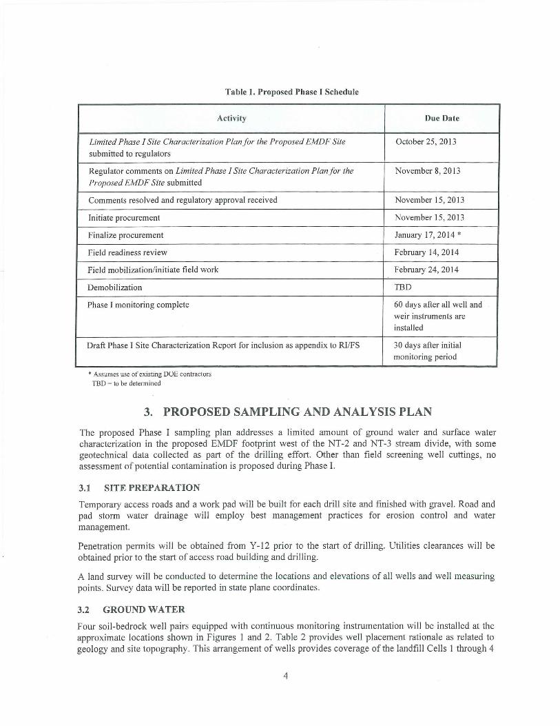
Table I. Proposed Phase I Schedule
Activity
Limited Phase I Site Characterization Plan for the Proposed EMDF Site
submitted to regulators
Regulator comments on Limited Phase I Site Characterization Plan for the
Proposed EMDF Site submitted
Comments resolved and regulatory approval received
Initiate procurement
Finalize procurement
Field readiness review
Field mobil ization/initiate field work
Demobilization
Phase I monitoring complete
Draft Phase I Site Characterization Report for inclusion as appendix to RI/FS
* Assumes use of existing DOE contractors
TBD = to be determined
Due Date
October 25, 2013
November 8, 2013
November 15, 2013
November 15, 2013
January 17, 2014 *
February 14, 2014
February 24, 2014
TBD
60 days after all well and weir instruments are
installed
30 days after initial
monitoring period
3. PROPOSED SAMPLING AND ANALYSIS PLAN
The proposed Phase I sampling plan addresses a limited amount of ground water and surface water characterization in the proposed EMDF footprint west of the NT-2 and NT-3 stream divide, with some geotechnical data collected as part of the drilling effort. Other than field screening well cuttings, no assessment of potential contamination is proposed during Phase I.
3.1 SITE PREPARATION
Temporary access roads and a work pad will be built for each drill site and finished with gravel. Road and pad storm water drainage will employ best management practices for erosion control and water management.
Penetration permits will be obtained from Y-12 prior to the start of drilling. Utilities clearances will be obtained prior to the start of access road building and drilling.
A land survey will be conducted to determine the locations and elevations of all wells and well measuring points. Survey data will be reported in state plane coordinates .
3.2 GROUND WATER
Four soil-bedrock well pairs equipped with continuous monitoring instrumentation will be installed at the approximate locations shown in Figures I and 2. Table 2 provides well placement rationale as related to geology and site topography. This arrangement of wells provides coverage of the landfill Cells I through 4
4

for the purposes of developing initial ground water table maps and flow nets , while maintaining consistency with the planned overall Phase II well array.
The four well pairs will be sited so as to provide ground water elevation data in and around the NT-3 valley, the area that would be occupied by EMDF Cells I through 4. Each well pair will consist of a shallow and deep well to monitor soil and bedrock aquifer zones and to provide data on vertical gradients. Shallow wells will be bored to the top of bedrock or a depth of 30 ft , whichever comes first, and screened at the bottom, and deep wells will be drilled into bedrock to a depth of 100 ft and screened at the most prolific water producing zone encountered within bedrock. Bedrock wells may be completed open hole if no dominant ground water zones are encountered and if wall stability allows.
Boreholes will be advanced through soils with a hollow-stem auger and through bedrock using air-rotary equipment. Borehole geology will be logged and screened by a qualified geologist. The soil interval in one borehole at each well pair site will be sampled at 5 ft intervals, or as dictated by field conditions, using a split-spoon sampler and blow counts recorded. Split spoon soil samples will be classified in the field. At least one undisturbed Shelby tube sample will be collected from each well site for laboratory permeability testing.
Wells will be constructed of nominal 4 in. diameter casing and screen. Bedrock wells will be constructed with mild steel conductor casing through the soil zone, and the riser and screen installed through the conductor casing to depth. Most of the wells will be constructed of polyvinyl chloride (PVC), but because the well pair near the crest of Pine Ridge is expected to be permanent, it will be constructed of stainless steel screen and casing. The annulus of each well will be filled with a filter pack of appropriately-sized sand extending to 1 ft over the top of screen, a 2 ft bentonite seal , and the remaining annulus sealed with cement-bentonite grout to the surface.
Table 2. Well Plan
Well Zone Casing Screen Formation Rationa le
Soil Stainless
Stainless steel Rome residuum steel Upgradient well pair; will remain
GWM-1 as part ofEMDF monitoring
Bedrock Stainless Stainless steel
Rome network steel or open hole
Soil PVC PVC Pumpkin Valley
GWM-2 residuum Pine Ridge slope and saddle
between NT-2 and NT-3 Bedrock PVC PVC Pumpkin Valley
Soil PVC PVC Maryville residuum
GWM-3 PVC or open South hillcrest Bedrock PVC
hole Maryville
Soil PVC PVC Maryville residuum NT-3 valley floor near wetland;
GWM-4 NT-3 ground water interaction;
Bedrock PVC PVC or open Rogersville - deep well will cross Rogersville-
hole Maryville Maryville boundary
GWM =Ground Water Monitoring
5

All wells will have concrete pads and be equipped with locking caps and protected as needed by bollards . Wells within the landfill footprint will be plugged and abandoned at the start of landfill construction.
Geophysical logs and packer flow tests or slug tests will be run in each well , as appropriate, prior to setting the casing. Geophysical logs to be run include: temperature profile, spontaneous potential , caliper, neutron density, electrical resistivity log (optional), heat pulse and impeller flowmeter, cavity sonar (if needed), open hole televiewer/digital video, and borehole orientation/verticality . Flow meter surveys will be used to identify areas of high inflow or outflow to the well and selected zones will then be isolated with packers for testing to estimate flow rates and transmissivity.
Wells will be developed by surging or pumping to settle the filter pack and remove fine materials prior to aquifer testing or installation of continuous monitors . Each of the eight wells will be equipped with a down-hole instrument sonde, such as a YSI EX0-1 , equipped with calibrated sensors for water depth (to be converted to elevation) and water quality parameters such as temperature, conductivity, pH, or oxidation-reduction potential. Data will be collected at specific intervals and recorded in either the sonde ' s memory or an on-surface data logger. Sonde calibrations will be checked and data collected at least weekly.
Groundwater monitoring data will be collected continuously for 30 to 60 days , or as appropriate for the meteorological conditions at the time, will be used as the basis for the Phase I report (see Section 4.3). Hydrographs relating groundwater elevation to rainfall will be used to document groundwater response to recharge. Groundwater monitoring is expected to continue during Phase II over the course of one year or more to capture seasonal variability and correlation to meteorological data collected at the Y-12 West meteorological station.
6
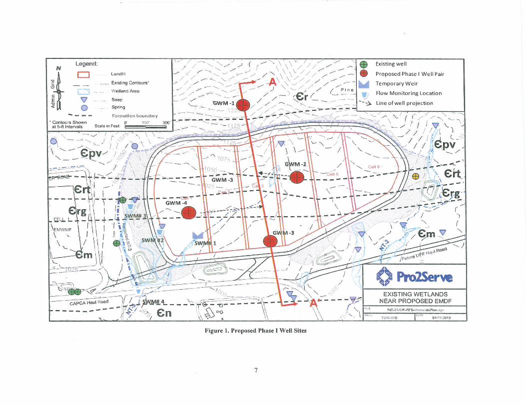
N Legend:
~t CJ
\J 0 ... _ - -
• Contours Shown at 5-rt Intervals
Landfill
Existing Contours·
Wetland Area
Seep
Spring
Form at ion boundar y
Scale m Feet: O' 150'
- / """'. , - _,. , I ( -..,\
~ " - --" -.....,__) j I I \. ·....___ ....... €)v/ /~~
"' _;_ - - - "'-., / ! l\ - .. -:::..o=--~-=-\ Ji ' ~~u- - - ,1. ;::? .
~
\ -,.,.
- ....... ~ ffi / ,/ '17 - .. '"". " I/ - / . ...-- : &
I . ... · ;::.- "'"', \ \ / / ,/ / - - w .......... , "' ,...... J ,..) -c. r \ \\\" / / / ,,,.. - - .. - ........
, ~ ~ ~ .-' . A \ / / " , "
Existing well
Proposed Phase I Well Pair
Temporary W eir '""" / _, / ......... \ \ // ,, - - I / ....__ /t --#"\ ,'\. '-' / / / ( " '"-· /. ~ ''-- -
- -- ..... _ -- . ~ ) _,...,_ ( - --;:i --,, " ~ -j - .._ .._,, / - ~r - - - - -;: _ . I ' • <,, °" - >
_.;/ . --- / / -- ~ - - - ' < '- { ( ,,. <. \_ - -- - -- - ~ - - ? I I ~ _,, ,, - - . .,, ,, . "'- ~ ,- , - - , \ ./ . I v · l.
,, / . ..WM ·1 / / / - "'-"-. - - : r r _ , , I / \ , , , , " ' , "'- ,,. , ' , I I . 6 _ " -~ - - - .. '...<. "' , - I I ; ~V
Flow Monitoring Location
Line of we II projection
I/ r; - / . , -I _.. ·, . " ~..-:.. _ .... - ~~ .
, \ v1-t., :=-=--::::.--·--1! ' 1-~-:. ~~ -·_, ·I -·
E9 If':~'-- - - ' ·---~:...(/, ,·€r.g ·
-"' / -· - - ~-- .. ( -~·--, .._,..~ - - ..... - - /' I'. I I
r· ~ (
e1\H,. ~--;;; _\ ... Gw;r::1,.. -. I' ,. • -- ~-a- , i rg4\-·l -1! .J~~ J, - - - . 'V\ / -1\r I / \~ . w t-lif I ' "' f:-
Q I 1\ / ~~\ SW"\~2\ 'sw 1 ~' 1\7 _..--2. ,
~ --> "' v.· -
I \\/ .., , ;, '\\ ~ '~ I- ---=-· 1 • ~ m \ '! \\"'~- y/ ~ _ / ~1 1 -- (' ProlServe ' ' ' . ''· ~ -- - ! / • . I' , '- _ _,, ,.,,.., ) \ ---- . ...____,_... /
_a -~~0Jd'' -~ '-~l' .' . \. ::::::.=- ·- --==---- ;;:' )..~ ,_ . EXISTING WETLANDS ) : ~-- ~ _ _!_f--~__L-""-=- :i?~~"- - '- _ 1::1A"": EAR PROPOSED EMDF ~ ~ -- , . ,, . _ - v,r l __ N~:..:.:.:..~::::-:=:::::;.::; '~~=": ~ 0/ -- " ~-·· -' '-~( - - - - .. - r Fl1E F!G-EMD<-FFS-WcllandsPlan .dgn ~ · - ~ ..:J--- 1(- - -~ · '-- ,,.-_::-.::-::-~· :.-- - - - ""'\ \-~ '\ 1· \ I"'" 0 111 312013 - - . ~. I J. M#'L--- ~~~--<> I . ' · , .~ •• ·~ -- CAPCA ·Haul Road . - !..• -':1 . - ~ I (\ , oo \ \ "
- - - - ~11~_1 "-9.><- vn \\ o~ G , - - - - - / 'JI "'-~ -~ . '
Figure 1. Proposed Phase I Well Sites
7

1240 __ · ·~ ! ~-1:--=J __ ~ 1240
1220 ___ Approximate EMDF Footprint::_ · __ .-- _ 1220 "-'---1----l-----l------'---!----+---f - ; - ·t---1200 _ _ _ _, __ .. _ ---l ' ' 1200
1180 1180 ~-+~ -- -
1160 1160
1140 1140
1120 1120
1100 -- - -~ - -- 1100
1080 1080
1060 1060 * 1040 1040 ':!=.. § 1020 1020 ~ ~ 1000 + 1000 w -~
980 980
960 960
940 940
920 920
900 ------- - -- 900
880 - 880
860 860
0
A 200 400 600
',
800 1000
Distance Along Section Cut (Feet)
1200
Figure 2. Conceptual Cross-section of the Proposed Well Pairs.
1400 1600
GWM-2 and GWM-4 are projected along strike into the line of section at their approximate surface elevations.
8
1800
A'
Q5 Q)
':!=.. c: 0
~ a; w

3.3 SURFACE WATER
Phase I surface water assessment within the EMDF footprint is confined to stream NT-3. The primary objective of collecting surface water data is to quantify the flows of NT-3, identify sources and proportions of flow (both surface and groundwater), correlation of meteorological conditions with surface and groundwater at the site, and to identify the interconnectivity ·of surface water to groundwater. During Phase I, four monitoring locations are recommended to characterize surface water and groundwater flow comprising stream NT-3 total flows.
The monitoring will be conducted initially for 30 to 60 days, or as appropriate to meteorological conditions. Surface water monitoring is expected to continue during Phase II over the course of one year
or more to capture seasonal variability and correlation to meteorological data collected at the Y-12 west meteorological station. Station specific information for each monitoring location is provided in Table 3.
One temporary square or v-notch weir and staff gauge will be installed at a suitable location on the east branch ofNT-3 (see Figure 3). The recommended construction material is a steel plate driven into the soil. To monitor flow seepage from the central and western branches of NT-3, two temporary flumes/staff gauges will be installed at suitable locations to measure and record flow rates using a continuous sensor. Due to the
Figure 3. Example of a Temporary Weir relatively small drainage area, topography, and existing flow of NT-3 , a 20-minute recording interval should be
sufficient to capture peak flows during rain events at the site.
To further delineate and predict the influence of meteorological and surface water conditions, a stilling well will be installed at each monitoring location and a multiparameter sonde utilized to record water level, temperature, and conductivity on 20-minute intervals. This data will be compared to nearby groundwater monitoring data to characterize the percent of groundwater of the overall flow during rainfall events.
Two temporary flumes , similar to the one shown in Figure 4, will be installed at suitable locations to measure and record data to monitor flow seepage from the central and western branches ofNT-3 .
The confluence of the three branches of NT-3 is immediately downstream of the proposed EMDF footprint. A continuous monitor will be installed at the existing constrictor plate/weir in the culvert under Haul Road to obtain cumulative flows of the reaches ofNT-3 that traverse the proposed EMDF site.
3.4 INSTRUMENTATION
Continuous monitors, similar to a YSI multi-probe and/or level sensor equipped to measure water level , conductivity, pH, and temperature will be utilized for ground water and surface water weir monitoring. Probes will typically be field checked and calibrated in situ every one to two weeks, dependent upon the potential for instrument drift and fouling. Each surface water monitoring station will be visually inspected after each heavy rain event for system integrity . Grab samples will be collected every four to eight weeks at each seep and the Haul Road culvert for to measure flow, temperature, pH, and conductivity.
9

Meteorological data would be collected from the Y-12 west meteorological station to correlate seasonal rainfall data with ground water response and surface water flows measured at the four stations .
Each instrument will be calibrated or standardized according to the manufacturers procedures. All calibrations will be recorded on an appropriate log sheet. Data verification should include review of the log sheets for calibration records. Calibration data recorded by the field staff should be compared to the criteria specified in the instrument operating procedures. Deviations from standard procedures will be documented.
Table 3. Surface Water Monitoring Stations
Location Pa rameters Frequency Instrumenta tion Rationale
SWM # l Level Every 20 Multi-parameter Downstream of two seeps along
Temporary Weir Temperature minutes Sonde NT-3 eastern branch, just upstream
Steel Conductivity Staff gauge of transition zone for the wetland
construction complex at the southwest corner of
the EMDF proposed footprint.
SWM #2 Level Every 20 Staff gauge Downstream of seep along NT-3
Temporary Temperature minutes middle branch, just upstream of
Flume Steel or Conductivity transition zone for the wetland
fiberglass complex at the southwest corner of the EMDF proposed footprint to
measure seep flow at this location.
SWM#3 Level Every 20 Staff gauge Downstream of seep along NT-3
Temporary Temperature minutes western branch, just upstream of
Flume Steel or Conductivity transition zone for the wetland
fiberglass complex at the southwest corner of
the EMDF proposed footprint to
measure seep flow at this location.
SWM#4 Level Every 20 Multi-parameter Immediately downstream of all
Haul Road Temperature minutes Sonde three branches ofNT-3 to capture
Culvert Conductivity Staff gauge total flow existing in the proposed
EMDF footprint area.
SWM =Surface Water Monitoring
3.5 WASTE MANAGEMENT
Soil and rock cuttings are expected to be uncontaminated because there is no evidence that the EMDF site has been impacted by industrial operations, waste disposal, or other contaminant releases. Cuttings from soil borings and well drilling will be piled at the drill site and screened for contamination by visual observation and use of field instruments (radiation meters, photo-ionization detectors). Samples will be collected and forwarded for laboratory analysis only in the event that field screening indicates contamination. The piled cuttings will be placed in 55-gallon drums or directly into a dump truck for disposal at the EMWMF if laboratory analyses confirm contamination.
10

Water produced during well development and well/aquifer testing will be discharged to the ground surface near the well site unless field screening of cuttings indicates the presence of contaminants . If contamination is suspected, produced water will be contained in a tank or carboy and transported to an appropriate ORR water treatment facility .
Sanitary wastes, such as paper and packaging, will be disposed in the sanitary waste dumpsters at the EMWMF offices, or in a dumpster placed near the field site. Portable toilets will be emptied and wastes disposed by a contractor.
4. DATA MANAGEMENT, INTERPRETATION, AND REPORTING
The primary purpose of environmental data management, interpretation, and reporting is to provide a system for efficiently generating, maintaining, and communicating scientifically defensible data that provide the basis for making sound environmental decisions.
4.1 VALIDATION
Field data acquired during Phase I activities will be reviewed daily by the field manager and weekly by the project manager or designee to ensure that data are collected according to procedure, calibrations are properly and timely conducted, and the quantity and quality of data meets Phase I requirements.
4.2 DATA MANAGEMENT
All Phase I numeric data will be entered into either an Excel spreadsheet or Access database format for star.age and use. Access to the spreadsheet or database will be limited so that data cannot be inadvertently modified or lost. Data entries will be checked for numeric accuracy and correct units.
Geologic and hydrogeologic maps, flow nets, and cross-sections will be constructed using methods in common practice. Numeric data will be reduced and presented in tabular format.
4.3 REPORTING
Results and interpretations from the Phase I characterization study will initially be reported to the FF A parties in a letter report. The same information will also be documented in an appendix to the 03 Rl/FS.
5. POST-PHASE I CHARACTERIZATION ACTIVITIES
Phase I is intended to provide TDEC with enough information to make an informed decis ion regarding site suitability, but will not provide sufficient data to support landfill design, modeling, or long-term monitoring.
The Phase II site characterization will build on the Phase I results, and is expected to include additional well pairs, well clusters (shallow, intermediate, and deep wells), extensive geotechnical exploration, longterm ground water and surface water monitoring, and soil and ground water sampling and analyses for contaminants.
11