lightning protectors
TRANSCRIPT

LIGHTNING PROTECTORS
HUBER+SUHNER
Edition 2007
Excellence in Connectivity Solutions
General, detailed selection flow chart for HUBER+SUHNER lightning protectors
For uncertainties and difficult cases contact our web site www.hubersuhner.com or call.
Final type selection
Basic decision -
protector principle
Quarter-wave protector preferred:
• lowest residual pulse
• highest current handling
• lowest PIM
• maintenance-free
RF, protection and
further specifications page 86page 54
page 62page 68
page 94
page 92
page 100
page 82
HUBER+SUHNER is certified according to ISO 9001 and ISO 14001.
WaiverIt is exclusively in written agreements that we provide our customers with warrants and representa-tions as to the technical specifications and/or the fitness for any particular purpose. The facts and figures con-tained herein are carefully compiled to the best of our knowledge, but they are intended for general in-formational purposes only.
HUBER+SUHNER AGRF Protection9100 Herisau/SwitzerlandTel. +41 (71) 353 41 11Fax +41 (71) 353 45 90www.hubersuhner.com
HUBER+SUHNER AGRF Protection9100 Herisau/SwitzerlandTel. +41 (71) 353 41 11Fax +41 (71) 353 45 90www.hubersuhner.com
HUBER+SUHNER – Excellence in Connectivity Solutions
HUBER+SUHNER is a leading global supplier of components and systems for electrical and optical connectivity in communications, industrial and transportation markets. HUBER+SUHNER can draw on core competences in the
areas of high frequency technology, fibre optics, cables and polymers. Working in close collaboration with our customers around the globe, we strive for excellence in the develop-ment and manufacturing of high quality products.
WAIVERIt is exclusively in written agreements that we provide our customers with warrants and representa-tions as to the technical specifications and/or the fitness for any particular purpose. The facts and figures contained herein are carefully compiled to the best of our knowledge, but they are intended for general informational purposes only.
HUBER+SUHNER is certified according to ISO 9001 and ISO 14001.
2300
2023
/08.
2006
COMMUNICATION
Communication Networks/Communication Equipment
TRANSPORTATION
Railway/Automotive
INDUSTRY
Instrumentation/Space+Defence/Industrial Wiring
HU
BER+
SUH
NER
® L
IGH
TNIN
G P
ROTE
CTO
RS
LightningProtectorSelection
START
Quarter-wave
protectorGas capsule
protector
Series3401/2/6/9
Series3410
no yesDC injectionDC blocking
highlowRF power
OperationF-range
Series 3409DC-800 MHz
>2.5 GHz
>1 GHz (DC-2.5 GHz)
DC-1 GHz
800-18(N)/7.5(7/16) GHz
OperationF-range
RF power
OperationF-range
Series 3408
>2.5 GHz
25-800 MHz25-2500 MHz
Series 3410
800-18(N)/7.5(7/16) GHz
Series 3401Series 3402
Series 3407Series 3400
Protection
standard enhanced
OperationF-range
MountingRF dataOutdoor
DetailOperation
F-rangeMountingRF dataOutdoor
InterfaceMountingRF dataOutdoor
InterfaceMountingRF dataOutdoor
DetailOperation
F-rangeMountingRF dataOutdoor
standard standard standardhigh high high
CW+peak power
Surgecurrent
handling
CW+peakpower CW+peak
power
Selectionfrom table
InterfaceN
Interface DIN7/16
InterfaceN
Interface DIN7/16
Selectionfrom table
Selectionfrom table
Selectionfrom table
H+Stype
H+Stype
H+Stype
H+Stype
H+S gas capsule type
Selection of suitable gas capsuleacc. to RFpower and
PIM
OperationF-range
InterfaceN
Interface DIN7/16
Selectionfrom table
H+Stype
Pure RFsignal
No DC/AC
highlow
yes no
DC-5.8 GHzN, TNC, SMA
(BNC)
Selectionfrom table
H+Stype
Series 3406

QUICK SELECTION REFERENCE10 YEARS WARRANTY FOR LIGHTNING PROTECTORS
Wa
r ra n t y
1 0 Y e
ars
HUBER+SUHNER AG warrants that this product will provide lightning protection during a period of 10 years after its purchase according to the protection specifications and characteristics given in the applica-ble product specification. Such warranty is subject to the proper maintenance of the product and its parts, technical expert installation and the parts’ regular re-placement (e.g. gas capsules, other parts with limited resistance to wear and tear, etc.), if necessary, in ac-cordance with the relevant product specifications.
Buyer’s sole remedy and manufacturer’s sole obliga-tion in the event of any breach of this warranty due to a failure of lightning protection is limited to the repair or the replacement of the damaged lightning protec-tor or to the refund of its purchase price, at the sole discretion of the manufacturer.
This warranty does not, with the exclusion of the warranty for lightning protection as specified herein, alter or affect the warranty and liabilities specified
for this product in the general conditions of supply of HUBER+SUHNER Switzerland(applicable specifically to the Wireless Division). Theproduct in all other aspects remains subject to the entirety of provisions set out herein. In particular, this limited warranty does provide neither for a liability for consequential damages nor for any liability for per-sonal injuries whatsoever.
Recommended HUBER+SUHNER protector group
Quick selection page Full range page
1. Quarter-wave protectors series 3400 + 3407 44, 45 54, 86
2. Gas capsule protectors Series 3401/02 + 3408 46 62, 68, 92
3. Fine protectors series 3403 50 74
4. Slim line gas capsule protectors series 3406 47 82
5. High-power/low IM series 3409 + 3410 (DC injection) 48, 49 94, 100
7. SEMPER™ -- 113
7. Signal/data line protectors series 3414 -- 104
8. High voltage DC block series 9077 -- 118
1
23
5
2
5
7
4
47
6
8

HUBER+SUHNER lightning protectors 1
Intr
oduc
tion
CONTENT
Introductionpage 6
Definitions and termspage 27
Quick selectionpage 37
Productspage 53
Accessoriespage 129
Application notespage 143
General informationpage 161
COMMUNICATIONOUR COMPANY
THE HUBER+SUHNER GROUP is a leading global sup-plier of components and systems for electrical and opti-cal connectivity. Our customers in telecommunications,industrial applications and transportation appreciatethat we are specialists with detailed knowledge of practi-cal applications. We offer technical expertise in radiofrequency technology, fiberoptics, cables and polymersunder one roof, thus providing a unique basis for con-tinual innovation focused on the needs of our customersall over the world.
Our motto is: «EXCELLENCE IN CONNECTIVITY SOLU-TIONS». At the heart of our offering is a broad range ofproducts that can be relied on to meet high quality stand-ards, backed up by flexible, dependable services withfast response times worldwide. We concentrate on com-plex applications that allow us to stand out by addingvalue with special product features, customer- specificinnovations, engineering and other services.
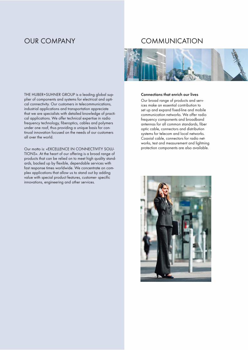
Connections that enrich our livesOur broad range of products and serv-ices make an essential contribution toset up and expand fixed-line and mobilecommunication networks. We offer radiofrequency components and broadbandantennas for all common standards, fiberoptic cable, connectors and distributionsystems for telecom and local networks.Coaxial cable, connectors for radio net-works, test and measurement and lightningprotection components are also available.

TRANSPORTATION INDUSTRY
Connections that get us movingAs one of Europe’s leading suppliers,HUBER+SUHNER offers a wide range ofproducts which provide the platform tobuild modern rail transport and automotivesystems. These products are developedfor high quality needs and specifically de-signed for applications such as: positioningas in GPS, cellular distribution for mobiletelephone access, WiFi distribution for in-ternet access, CCTV for video surveillance,passenger infotainment systems for realtime passenger information and entertain-ment, OTMR for train diagnostics duringoperation, inter vehicle jumper systems andprofiles for safety and comfort.
Connections that add valueOur components and system solutions aresuitable for specialised applications in avia-tion, space, defence, and medical technol-ogy. Our products are superior, providingconstant reliability even under extreme con-ditions: from copper cable to optical con-nections and high frequency components.

HUBER+SUHNER lightning protectors4

HUBER+SUHNER lightning protectors 5
Intr
oduc
tion
page
Introduction 6
Lightning basics 7
Creation and threat of lightning 7Electrical specifications and effects of earth lightning 9Resistive coupling 12Magnetic field coupling 13Electrical field coupling 13
Lightning protection 14
Basic principles of lightning protection 14RF lightning protector principles 15Lightning protectors with gas capsules 16Lightning protectors with quarter-wave stubs 17
HUBER+SUHNER strengths, know-how, qualityand reliability 19
Outstanding know-how 19Important test procedures and facilities 20 Measurement of RF characteristics 20 Measurement of the residual pulse 20 Measurement of passive intermodulation 23 Other available tests 24References and company approvals 24ISO certificate 24Multiple benefits for HUBER+SUHNER customers 25
INTRODUCTION

HUBER+SUHNER lightning protectors6
HUBER+SUHNER has been active in the field of co-axial RF components for over 50 years now. This com-mitment to connector and cable design led to activitiesfor solving technical problems related to coaxial trans-mission line surges.
In the sixties and seventies, the harmful effects of nu-clear weapons on electronic systems became known.The pace at which electronically controlled weaponsystems were developed during this «cold war» periodtriggered a huge surge in the demand for protectivedevices against NEMPs (Nuclear ElectromagneticPulses). Cooperating closely with university researchdepartments, HUBER+SUHNER created the know-howrequired for the development and production of effec-tive NEMP protectors. Closely related is the fact thatSwitzerland was one of the first countries to make itscivil protection and military installations impervious toelectromagnetic interference.
The experience gained during this period proved inval-uable in later years. As the integration and miniaturiza-tion of electronic circuitry increased, the sensitivity ofthese circuits to overvoltage grew, since ever-smallerenergy quantities were sufficient to cause irreversibledamage. HUBER+SUHNER responded to this trendby continuously pushing the frontiers of its know-how,and today it is in a position to supply a wide range oflightning protection components designed to ensuremaximum quality and reliability.
In telecommunications equipment, special attentionmust be paid to protect against energy interference bylightning. This is a field in which HUBER+SUHNER hasdeveloped a wide variety of RF protectors.
They play a particularly important role in the hugenumber of mobile radio base stations that have beenbuilt over the past few years. They are indispensablefor effectively minimizing the maintenance and repairrequirements of these systems. This is of immense sig-nificance to operators who want not only to preventrevenue losses, but also image losses as a result ofinadequate availability of their networks.
Today, HUBER+SUHNER is in a position to offer a mul-tilevel concept ranging from standard to fine lightningprotection components for RF transmission and symmet-ric data lines. Sophisticated unique designs meet themost demanding application requirements.
INTRODUCTION

HUBER+SUHNER lightning protectors 7
Intr
oduc
tion
Creation and threat of lightning
Strokes of lightning kill more people in Europe andNorth America each year than floods or tornados,causing billions of dollars in damage. The numberof lightning-induced forest fires throughout the worldalone runs to more than 10,000 annually.
Since the experiments performed by B. Franklin, Romasand other lightning researchers we know that lightningis a physical phenomenon. It is created in thunderstormcells. The cold storm front, which penetrates a hot area,forces the warm and humid air to rise. Temperaturedecreases with altitude and the water vapor condensesto small water droplets. This process is accompanied bythe creation of heat which accelerates the air current.Reaching altitudes with subzero temperature, the waterdrops freeze to ice crystals. Again heat is producedsimultaneously. The air speed increases once more– reaching a velocity of several hundred km/h – andpropels the small ice particles to higher altitudes of upto 12 km. The growing ice crystals convert to hail stoneswhich fall down due to their weight or remain in certainbalanced positions. This causes electrons being strippedfrom the ice crystals. As a result of this process, chargesare separated across a wide surface area. With fieldstrengths of several 100 kV/m, discharges may be trig-gered in the form of cloud-to-cloud or cloud-to-earthlightning strokes, and in rare cases even as earth-to-cloud lightning.
Mechanism of thunderstorms
- 20 °C
- 10 °C
0 °C
sun-heated aircold storm front
LIGHTNING BASICS

HUBER+SUHNER lightning protectors8
The electrical charge of a lightning stroke may exceed100 As. It is discharged to the earth within 10 to 100ms. The temperatures created in the lightning channelare higher than those on the sun’s surface. The air isheated so quickly that it expands with the force of anexplosion. The resulting sound waves can be heardas «thunder» as far away as 20 km. Lightning flashesmay be as long as 50 km, but are only a few milli-meters thick.
Lightning variants
Thunderstorms occur most frequently in the tropicaland subtropical belts surrounding the earth, where thetemperatures and the air humidity are very high.
At any given time, almost 2000 thunderstorms are inprogress on earth, and every 1/100 second or 6000times a minute a bolt of lightning strikes the earth.
For many reasons the world is mapped concerningthunderstorm days – or the ground flash density (GFDmaps) – and number of hits per area (square miles,square km, etc.). Also satellite flash event maps areavailable.
GFD map of the USA
In the USA alone, lightning strikes 40 million timeseach year. Its occurrence in the USA is greatest withina 100-kilometer-wide strip crossing the state of Florida,called «lightning alley». In this area, thunderstorms canbe observed on 90 days every year.
4060
60 60 40
140
20
10
5
1
10
60
80
30
140
180
5
180
10 10
5
5
20
40
4040
105
1
80
80
4040
60
100 10
6040
20
100
60
60
100
14060
8060 120
8040
40
100205
5
40
20
10
10 5
140100
10
5
1
100
80 5
40120
60
60 50
402010
5
1
10 20
World map of isokeraunic level (annual number of days when thunder is heard)

HUBER+SUHNER lightning protectors 9
Intr
oduc
tion
Such maps are an important tool to determine the hitrisk for a certain location. But for a final conclusiona lot more factors have to be considered, and thecalculation models consist of complicated formulas.Considerations are altitude, the height of the building,the surrounding profile, buildings in the neighbourhood,the distance to water, earth material and even if a light-ning protection system is installed, to name only a fewof them. In many cases – especially in the areas oflower latitude, the more northern and southern regionsof the world – the theoretically calculated hit risk mightlook negligible. But hot spots of many countries canhave multiple GFD values compared to average (e.g.Germany with more than tenfold values). Network op-erators have further to multiply the single BTS hit risk bythe number of their sites. IEC 61024 provides a calcu-lation formula for a rough estimation.
Interferences of close by hits, which can easily outnum-ber those of direct ones, have also to be considered.
The lightning hazard to electric and electronic equip-ment consists in the interferences of direct lightningcurrent injections and high surge voltages induced bythe electromagnetic field of nearby lightning channelsor down conductors. The damage caused dependson the energy involved and on the sensitivity of theelectronic systems. The electric surge pulse generatedby lightning is called LEMP (Lightning ElectromagneticPulse).
Lightning research has produced a large numberof suitable protective measures that are reflected ininternational and national safety standards. These in-structions and recommendations for the installation oflightning protection systems together with the applica-tion of HUBER+SUHNER lightning protectors providea high degree of safety for electronic equipment.
The installation of a lightning protector costs only afraction of today’s transceiver equipment. In the caseof damage by EM interference in general natural, butalso man-made the repair of the equipment but alsothe loss of revenue and good reputation due to down-time have to be considered.
All in all, there is not left much choice to an operator ofmobile communications or other wireless services thanto establish the best protection available.
Electrical specifications and effects of earth light-ning
Here, we will only consider cloud-to-earth lightning,which has the greatest damage potential. This type oflightning is divided into positive and negative lightning,depending on the polarity of the cloud charge.
Positive cloud-to-earth lightning is the most critical, dueto the duration of the lightning current pulse. With amaximum current of several 10 kA, it may last longerthan 2 ms. The electrical charge is typically higherthan 50 As.
Negative cloud-to-earth lightning starts with a lightningcurrent pulse whose maximum amplitude amounts alsoto several 10 kA, but lasts merely 1/10 of the time ofa positive one. Its peculiarity lies in the subsequentsmaller multiple discharges, which may result in a totalduration of the lightning of over one second and a to-tal electrical discharge of over 100 As.
This produces the following basic, schematic lightningcurrent patterns:
1) Positive or negative lightning current pulse ofseveral 10 kA and less than 2 ms duration (TS):
Tst
imax
i

HUBER+SUHNER lightning protectors10
2) Positive or negative lightning current pulse as 1),with subsequent long-duration current of about 100 A during a period of less than 500 ms (TI).
3) Sequence of negative lightning currents with a first
lightning current pulse according to 1) followedby subsequent lightning currents up to 10 kA. Thebreak times between the lightning current pulsesare shorter than 100 ms (TP).
4) Sequence of negative lightning currents accordingto 3), with integral long-duration current accordingto 2).
On the basis of these lightning current patterns, CIGRÉand IEC 61312-1 defined 3 groups oflaboratory-simulated lightning currents:
Group 1
Lightning current of positive or negative polarity, firststroke – wave form 10/350 μs
Group 2
Lightning current of negative polarity, subsequentstroke – wave form 0.25/100 μs
Group 3
Lightning current of positive or negative polarity, long-duration stroke – DC 0.5 s
The most important parameters of lightning are the fol-lowing:
Lightning current amplitude îL – determines theresistive effects mentioned belowAverage steepness of the lightning current diL/dt– determines the resistive and magnetic couplingeffects mentioned belowTotal charge Q L * dt (unit As or C) – de-termines the energy release/conversion at the hitpointSpecific energy (action integral)
L2 2s) – determines
all heating and electrodynamic effects along thedown-conducting path.
•
•
•
•
Tlt
i
I
current pulse long-duration current
t
i i i
i
1st current pulse 2nd current pulse 3rd current pulse
1st current pulse 2nd current pulse 3rd current pulse
t
i
t
i
t
i
T l
Tp t
i i i
long-duration current

HUBER+SUHNER lightning protectors 11
Intr
oduc
tion
IEC 61000-4-5 defines a combined 1.2/50 μs voltageand 8/20 μs current test pulse for surge protectiondevices to determine their protection performance.Despite it’s relevance for general induction and power-switching interferences, this pulse is used for the de-scription of the protection quality also of lightning pro-tectors worldwide. Protection performance data showresidual pulse values as a result of a 1.2/50 μs;8/20 μs combination generator pulse.
100
90
80
70
60
50
40
30
20
10
0
10 100 1000 10000 100000 1000000
Comparison of the frequency spectra of a genuine lightning current surge (blue - according to K. Berger) and a test current surge
10/350 μs (red - according to IEC 61312-1)
Am
plitu
de[%
]
Frequency [ Hz ]
The diagram shows that a 10/350 μs test pulse is agood match to a first-stroke of lightning. This is consid-ered in IEC 61024-1 «Protection of structures againstlightning». Therefore, it is most suitable to test protec-tion devices. HUBER+SUHNER test their lightning pro-tectors according to this pulse regarding the lightningcurrent resistivity (also called current handlingcapability).
The frequency spectrum of the LEMP is also of interest,especially for RF applications. It reaches several100 kHz (NEMPs about a thousandfold). This is im-
portant for certain lightning protection solutions in RFengineering applications described below:

HUBER+SUHNER lightning protectors12
Lightning effects in radio transceivers
iL
UD
UE RE
LD
Data/telephone(Far-earth)
Far-earth
Resistive coupling
Partial lightning currents are coupled into all objectswhich are electrically connected to the lightning path.
This results in:
Earth potential rise (of the transmitter or building),which is the voltage drop over the earth resistancecaused by the lightning current amplitudeUE = îL* RE.
Assuming realistic values of îL = 100 kA and RE =
will be UE =1000 kV(!) of potential rise against far-earth (which is the potential of all connected powersupply, data and telephone lines).
•
Voltage drops over inductances, as each conductorprovides, caused by the average steepness of thelightning current UD = LD * diL/dt. Assuming real-istic values of subsequent lightning current pulseswith di/dt = 100 kA/μs and LD = 10 μH (which istrue for a down-conductor length of 10 m along abuilding or mast), the result will be UD =1000 kV(!)potential rise at the top against the ground of astructure.Longitudinal voltages over screened and coaxialcables.In general potential differences in electronic equip-ment.
•
•
•
The most interesting effects of lightning on electric and electronic equipment are the following:

HUBER+SUHNER lightning protectors 13
Intr
oduc
tion
Magnetic field coupling
The lightning current of near-hits or even a down- con-ducted one of the existing LPS (Lightning ProtectionSystem) induces surge currents and voltages in anyeffective electrical loop. This is determined by the aver-age steepness of the lightning current as well and fol-lows the formula:U = – M * diL/dt (M for mutual inductance).
Electric field coupling
The effects of the high and changing electrical fieldstrength right before the hit occurs is normally negligi-ble when considering a minimum of protection meas-ures.
Induction circuit
Electromagnetic interference of nearby lightning hits or even the LPS itself
Bonding bar
Power supply
Earth termination system

HUBER+SUHNER lightning protectors14
LIGHTNING PROTECTION
Basic principles of lightning protection
To protect electronic equipment, several different as-pects must be considered.Well-proven basic principles are shielding (Faraday’scage, armed concrete, screened cables), bonding andgrounding. The basic idea is to protect equipment andpeople against lightning by conducting the lightningcurrent to ground via a separate preferential solid pathand reduce the electromagnetic field.Today a lot of international and national rules exist toemploy all well-tried measures to protect life, structuresand equipment.Account must be taken of the most important interna-tional standards, such as IEC 61024-1 and 61312-1(protection of building structures against lightning andprotection of information systems against LEMP -
LPZ OA
LPZ OB
LPZ1
LPZ2(BTS)
RERE
mains, data
including radio transmitters) and others. They all definethe proper planning, installation and inspection of ef-fective lightning protection systems (LPS).
According to IEC 61312-1, the entire installation is clas-sified into different lightning protection zones (LPZ):
LPZ 0A
The zone where a direct hit is possible and whereobjects must be capable of carrying the full lightningcurrent. Also, the unattenuated electromagnetic fieldis very dangerous (lightning current test pulse of firststroke 10/350 μs).
LPZ 0B
The zone where a direct hit is not possible, but theunattenuated electromagnetic field is present (lightningcurrent test pulse 10/350 μs). This zone is determinedby the external lightning protection system consisting ofthe air termination, down conductor and earth termina-tion system.
LPZ1
The zone where a direct hit is not possible and the cur-rents in all conductive components are lower than inLPZ 0A and LPZ 0B. In this zone, the electromagneticfield is attenuated according to the screening meas-ures applied. RF, signal and supply lines leading intothis zone can be protected by surge protection compo-nents (8/20 μs). They may be based on a number ofdifferent operating principles.
The transition between LPZ0 and LPZ1 is the most im-portant one. At this point all crossing conductive partsmust be connected to the bonding bar. Signal andtransmission lines have to be equipped with lightningprotection devices which are able to carry partiallightning current (10/350 μs).
If a further reduction of the current or of the electricfield is necessary, additional subsequent zones mustbe established (LPZ2, etc.). Additional surge protec-tion components applied here form the fine protectionsystem complementing the standard protection ensuredby zone LPZ1.

HUBER+SUHNER lightning protectors 15
Intr
oduc
tion
For optimum protection, all electric supply and signallines should enter the protected area at one singleplace. At this point, they must be connected to thebonding bar by surge protection devices. At everyinterface between one LPZ and the next, the potentialequalization must be established like this.This classifies lightning protectors to be a part of thebonding system. They provide basically an interfer-ence event triggered bonding for signal-carrying lines.Special lightning protection principles for RF applica-tions allow a continuous bonding of lines.The grounding must always be in accordance with IEC61024-1.The grounding of the installed lightning protectors,their connections to the bonding bar of the structureor equipment have to be prepared very carefully toachieve the lowest possible resistance and inductanceto ground (refer to section «application notes»).
RF lightning protector principles
Overvoltage protection in the field of RF engineeringmust meet special requirements in comparison withgeneral, low-frequency signal transmission and powersupply applications. In particular, coupling capacitanc-es towards ground must be minimized in order to pre-vent any significant loss of the transmitted RF signals.This essentially rules out the wide-band application ofvaristors and semiconductor diodes.
There are three principal designs for coaxial lightningprotection components in RF applications:
Gas capsule (spark gap) – the well-known princi-ple in electronics for many years
and, in addition, two principles which make use of thelimited frequency range of the LEMP and the NEMP(refer to Fig. «Comparison of the frequency spectra ofa genuine lightning current surge and a test currentsurge 10/350 μs on page 11). They allow to transmitonly RF signals within a certain specified range:
•
High-pass – a principle which allows only limitedlightning current handling capability but ratherlarge bandwidths and low residual energy.
Bandpass – a very effective principle whichHUBER+SUHNER employs with their quarter-waveprotectors featuring the lowest possible inductance.The operation frequency band can be properly ad-justed to any application.
•
•
Gas capsule type
High-pass type
Bandpass type

HUBER+SUHNER lightning protectors16
Lightning protectors with gas capsules
In the event of a voltage surge, a gas section betweenthe inner and the outer conductor of the coaxialtransmission line will spark over, resulting in potentialequalization to ground. This system works as a volt-age-dependent switch that is automatically turned onand off. This design features a special gas-filled surgeprotection device (abbreviated SPD).
Operating principle of gas lightning protectors
If lightning strikes the antenna mast or the antennaitself of a transceiver system, a current will flow towardthe transceiver. Part of the current will be directly dis-charged through the antenna mast to the ground, andthe other part will flow through the RF cable to thelightning protector installed at the entry point into thebuilding or equipment. An interference voltage mayalso be induced in the RF cable by a lightning strikein the proximity of the station, causing an interferencecurrent to flow toward the equipment.
The SPD incorporated in the lightning protector sparksover (thereby becoming low-ohmic), equalizing thepotential between the inner conductor and the ground.The current and thereby the energy of the lightningare discharged to the ground. Care must be takento ensure that the current will be discharged on theoutside of the building or equipment, and not inside. Itis therefore important to install the actual surge protec-tion device on the outside, the so-called unprotectedside, in order to prevent any interference voltage frombeing induced in the protected zone. This is also truefor other protection principles.
Once the interference subsides, the gas capsule willrevert to its original condition, i.e., it will again becomehigh-ohmic, and the system will be able to continue op-eration in the same way as before.
To understand the existing interrelationships and alsoto compare this system to other principles, let’s con-sider the mode of operation for the gas capsule:
«Load» stands for the electronic equipment that has tobe protected. The surge protection device is symbol-ized by the discharge capsule.
The surge protection capsule consists of two electrodesthat are insulated by a small ceramic tube. It’s staticsparkover is determined by the gas properties, its pres-sure, and the electrode gap.
In the event of a surge, a current will flow through thecable to the equipment, represented here as a surgewave.
surge wave
lightning protector
line
load
surge wave
line
spark-over initiated

HUBER+SUHNER lightning protectors 17
Intr
oduc
tion
The voltage across the surge protection capsule thenrises very rapidly. When the dynamic spark-over volt-age has been reached, the surge protection capsulewill ignite and become conductive. At this moment, thevoltage across the surge protection capsule (called theglow-arc voltage) is between 72 and 90V. This col-lapses to 10 – 20V (called the arc voltage), as the cur-rent rises. The dynamic spark-over voltage of the surgeprotection capsule is a function of the pulse rise time.
The surge protection capsule, once it sparks over, cre-ates a potential equalization between the inner andthe outer conductor (ground) of the coaxial transmis-sion line. The current flows along the path of leastresistance through the surge protection capsule tothe ground. Only a very small portion of the energy,the so-called residual pulse, reaches the equipment.Its magnitude is determined by the surge protectioncapsule characteristics, the interference pulse rise time,and the ground conductor impedance (determined bythe quality of the lightning protection system).
After the interference has subsided, the surge protec-tion capsule is extinguished, reverting to its originalhigh-ohmic condition.
Gas capsule protectors can generally be used in wide-band applications from DC to over 2.5 GHz, latestdesigns up to 6.0 GHz. The upper limit for theoperating frequency range is determined by the ca-pacitive characteristics of the surge protection capsule.
Gas lightning protectors allow DC to be carried andthus tower-mounted electronic equipment to be fedpower via the coax line.
Lightning protectors with quarter-wave ( /4)shorting stub
This technology is based on a quarter-wave trans-formation. The coaxial shorting stub applied for thispurpose is short-circuited at its end, and its length ismatched to the mid-band frequency of the operationband. It thereby forms a bandpass filter. Its bandwidthcan be adjusted up to ± 50% of the centre frequency.
Operating principle of quarter-wave lightning protectors
surge flows to ground
protectorextinguished

HUBER+SUHNER lightning protectors18
Since lightning interferences have a low frequencyspectrum as described above, the shorting stub acts asa short circuit, conducting the current to the ground.
The basic principle for the RF signal transmissionthrough a quarter-wave lightning protector is describedin the following:
In regular operation, the RF signal reaches the entryof the shorting stub (shown here as point 1). It thenruns along the shorting stub up to the short (point 2).This corresponds to a 90° phase shift. At the short, thesignal is reflected (point 2') – a sudden phase shift of180° is created – and flows back to the start of the
shorting stub (point 1'), where it arrives after another90° phase shift. As a result, the reflected signal isagain in phase with the arriving signal. Therefore, theRF signal does not «detect» the short.
Standard quarter-wave lightning protectors are limitedin bandwidth compared with gas lightning protectors,but offer considerably lower residual pulses and ahigh-current-handling capability. This is maintainedeven under multiple loading.
The operating principle of quarter-wave lightning pro-tectors allows them to be manufactured for operatingfrequencies ranging from some MHz to more than 20GHz (basically up to the frequency limit of the coaxialinterface of the protector). The lower end of the availa-bility range is determined by the increasing geometriclength of the quarter-wave shorting stub.
They can be designed to show very low intermodula-tion values. The fact that they are maintenance-free isan important advantage for their use in the field.The residual pulse of the quarter-wave lightning protec-tor has a considerably lower voltage amplitude (andthereby also energy) than that of the gas lightningprotector.Unlike the gas capsule lightning protector, it is not pos-sible to carry any DC here, since the inner conductor isconnected directly to the ground.

HUBER+SUHNER lightning protectors 19
Intr
oduc
tion
HUBER+SUHNER mainly applies copper alloys for thecontact and housing components of its lightning protec-tion components. Their specific composition is selectedon the basis of the loads they are subjected to. Contactsurfaces are gold- or silver-plated. Housing surfacesreceive the proven HUBER+SUHNER proprietarySUCOPLATE® surface plating. This is a nickel-free alloyoffering both, an excellent contact surface for RF appli-cations – including low IM values – and outstandingcorrosion resistance. Detailed information on this plat-ing is included in our data sheet «HUBER+SUHNERSUCOPLATE® Surface Plating for RF Components».
Gas capsule lightning protector with SUCOPLATE® surface
The main insulation material used is PTFE. Seals consistof silicone rubber.
Outstanding know-how ensures optimum techni-cal parameters
The following technical parameters are especially im-portant for users of lightning protection components inRF engineering applications:
Operating frequency rangeReflection characteristics (VSWR or return loss)Insertion lossLightning-current-handling capability and residualpulse voltage and energyIntermodulation characteristics
The mastery of the first three design feature categoriesis one of the longest-standing, continuously refinedcore competencies of HUBER+SUHNER.
HUBER+SUHNER has focused much of its efforts onthe problem of passive intermodulation (IM) sincethe early nineties. This coincides with the increas-ing importance of this question in the area of mobileradio telecommunications as a result of the growingnumber of ever-denser mobile radio networks. Today,HUBER+SUHNER belongs to the small circle of com-panies leading the efforts to push the standardizationof intermodulation testing of RF components.
This allows HUBER+SUHNER to supply its lightningprotection components as well as all other RF compo-nents such as coaxial connectors, coaxial cable assem-blies, filters, power splitters and antennas according toIM specifications.
All areas of competence mentioned up to now are inti-mately linked with extensive knowledge in the fields ofmaterials technology, surface-plating and metalwork-ing. This is a precondition for ensuring excellent RF andIM characteristics and the power-handling capabilitiesof these components, their geometric dimensions andspecial materials of construction in addition to their me-chanical stability and resistance against environmentalinfluences.
••••
•
OUR STRENGTHS, KNOW-HOW, QUALITY AND RELIABILITY
HUBER+SUHNER lightning protectors20
Important test procedures and test facilities en-sure quality and reliability
On the basis of what has been said above, we willnow look at the most important related tests:
Measurement of the RF characteristics
State-of-the-art network analyzers are available formeasuring the RF characteristics. They allow the pre-cise testing of the return loss (VSWR) and insertionloss.
Measurement of the residual pulse voltage and lightning current resistance
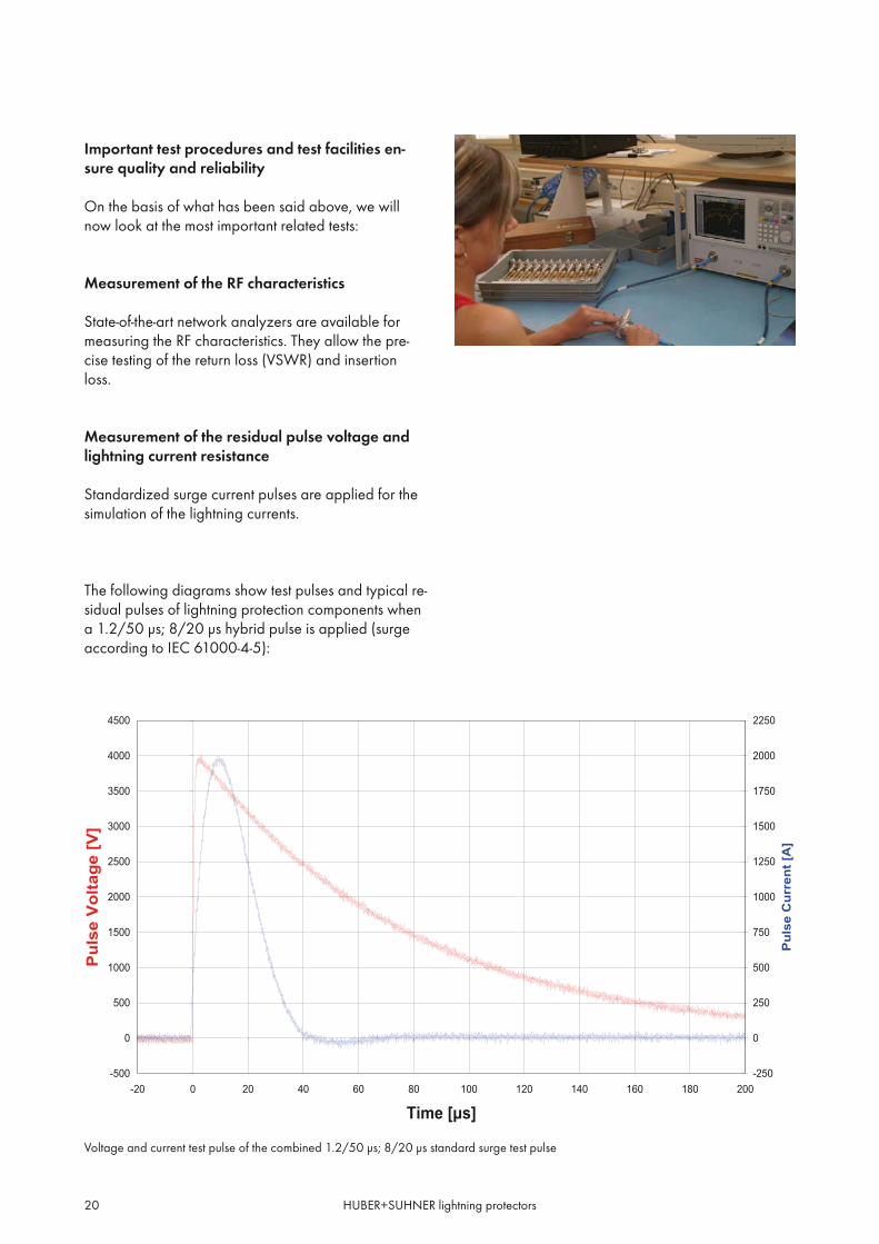
Standardized surge current pulses are applied for thesimulation of the lightning currents.
The following diagrams show test pulses and typical re-sidual pulses of lightning protection components whena 1.2/50 μs; 8/20 μs hybrid pulse is applied (surgeaccording to IEC 61000-4-5):
Voltage and current test pulse of the combined 1.2/50 μs; 8/20 μs standard surge test pulse
-500
0
500
1000
1500
2000
2500
3000
3500
4000
4500
-20 0 20 40 60 80 100 120 140 160 180 200
Time [μs]
Pul
se V
olta
ge [V
]
-250
0
250
500
750
1000
1250
1500
1750
2000
2250
Pul
se C
urre
nt [A
]

HUBER+SUHNER lightning protectors 21
Intr
oduc
tion
Residual pulse of gas capsule lightning protectors series 3401/3402 and series 3408 with high-pass filter (both with 230V gas capsule)
Quarter-wave lightning protectors
Residual pulse of quarter-wave lightning protectors series 3400 and series 3407 with high-pass filter (both GSM band types)
Typical residual pulse characteristic of HUBER+SUHNER protectors
Gas capsule lightning protectors
The residual voltage of the series 3402 is approx.650 V. However, the residual energy is very low com-pared with the input energy. In the case of the series
3408, the residual voltage is yet again reduced byabout 40%. This results in a residual energy of approx.60% compared with the series 3402.
-100
0
100
200
300
400
500
600
700
800
-50 0 50 100 150 200 250 300
Time [μs]
Puls
e Vo
ltage
[V]
-300
-200
-100
0
100
200
300
400
500
-50 0 50 100 150 200 250 300 350 400 450 500Time[ns]
Puls
Vol
tage
[V]
-4
-2
0
2
4
6
8
-5 0 5 10 15 20 25 30 35 40 45 50
Time [μs]
Puls
e Vo
ltage
[V]
Series3400
-1.5
-1
-0.5
0
0.5
1
1.5
2
-100 -50 0 50 100 150 200 250 300 350 400 450 500
Time [ns]
Puls
e Vo
ltage
[V]
Series3407
Series3408
The quarter-wave lightning protector does not requireany response time. With its filter characteristic, it re-duces the standardized input pulse (1.2/50 μs with4 kV) to approx. 7 V. This translates into a residualenergy that is 70 times lower than that of gas lightningprotectors without high-pass filter. Quarter-wave light-
ning protectors with high-pass filter have a residualvoltage that is 80% a further lower. The most importantfact, however, is the residual energy reduction factorof 2000, which means a reduction factor by 100000compared to a standard gas lightning protector.
Series3402

HUBER+SUHNER lightning protectors22
Principle Series Connector interface Surge current handling capability with
test pulse 10/350 μs test pulse 8/20 μs
Gas capsule3401, 3402, 3403, 3408,3409, 3410
N and 7/16 8 kA 30 kA
Gas capsule 3406 all interfaces 2.5 kA 10 kA
Quarter-wave 3400, 3407 7/16 50 kA 100 kA
Quarter-wave 3400, 3407 N 25 kA 50 kA
The protection effectiveness is most clearly illustratedby considering the input surge pulse and the resultingresidual pulse at the output of the lightning protectoron an identical time scale.
-500
0
500
1000
1500
2000
2500
3000
3500
4000
4500
-20 0 20 40 60 80 100 120 140 160 180 200-250
0
250
500
750
1000
1250
1500
1750
2000
2250
-100
0
100
200
300
400
500
600
700
800
-20 0 20 40 60 80 100 120 140 160 180 200-4
-2
0
2
4
6
8
-20 0 20 40 60 80 100 120 140 160 180 200
Input surge pulse
Residual pulse (gas capsule protector)Residual pulse (quarter-wave protector)
HUBER+SUHNER has standardized generatorsfor generating surge currents with amplitudes up to 25 kA, for 10/350 μs test pulses (first stroke) and upto 100 kA for 8/20 μs test pulses.
NEMP can also be tested up to 12 kV, 5/200 ns.
To determine the lightning current handling capabilityof lightning protection components, HUBER+SUHNERalso benefits from the services of external test labo-ratories with surge current generators up to 100 kA(10/350 μs pulse).
The lightning protection zone determines the re-quired current-handling capability. The followingtable shows the surge current handling capability of
HUBER+SUHNER lightning protection components onthe basis of the standardized test pulses:
HUBER+SUHNER lightning protectors 23
Intr
oduc
tion
The following figure shows the basic design of the setup:
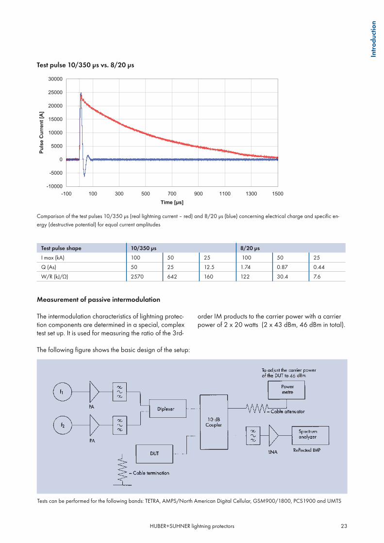
Test pulse shape 10/350 μs 8/20 μs
I max (kA) 100 50 25 100 50 25
Q (As) 50 25 12.5 1.74 0.87 0.44
2570 642 160 122 30.4 7.6
Tests can be performed for the following bands: TETRA, AMPS/North American Digital Cellular, GSM900/1800, PCS1900 and UMTS
Comparison of the test pulses 10/350 μs (real lightning current – red) and 8/20 μs (blue) concerning electrical charge and specific en-
ergy (destructive potential) for equal current amplitudes
Measurement of passive intermodulation
The intermodulation characteristics of lightning protec-tion components are determined in a special, complextest set up. It is used for measuring the ratio of the 3rd-
order IM products to the carrier power with a carrierpower of 2 x 20 watts (2 x 43 dBm, 46 dBm in total).
46
-10000
-5000
0
5000
10000
15000
20000
25000
30000
-100 100 300 500 700 900 1100 1300 1500
Test pulse 10/350 μs vs. 8/20 μs

HUBER+SUHNER lightning protectors24
ISO certificate
High-quality products and supplier relationships havealways been a top priority for HUBER+SUHNER. Afterhaving already been confirmed by the Swiss forerun-ner movement, the HUBER+SUHNER quality systemwas very soon acknowledged by the international ISOquality certificate. This much sought-after certificate ac-cording to ISO 9001, which must be earned over and
over again, has been awarded to HUBER+SUHNERwithout interruption since 1990. The fact thatHUBER+SUHNER is also prepared to meet specificcustomer quality standards exceeding those of ISO9001 is amply proved by a large number of success-fully passed customer audits.
References and company approvals
HUBER+SUHNER lightning protection componentshave been approved by the following leading OEMsof telecommunications equipment:
AlcatelCiscoEricssonLucent TechnologiesMotorolaNokiaNortelSiemens etc.
••••••••
Operators of analog and digital mobile radio net-works TETRA, AMPS, GSM900/1800, UMTS, IMSbands 2.4/5.7, WiMAX, WLAN and homeland secu-rity in the following countries apply HUBER+SUHNERlightning protectors:
Australia, Austria, Belgium, Canada, China, France,Germany, Hong Kong, Hungary, India, Israel, Japan,Kuwait, Malaysia, Morocco, Netherlands, Norway,Philippines, Poland, Portugal, Singapore, South Africa,South Korea, Spain, Sweden, Thailand, USA.
Other available tests
Additional technical specifications are possible on thebasis of the testing classes of the relevant IEC or MILstandards:
Operation temperature rangeTemperature shockHumidityCorrosion (salt mist, industrial atmosphere)VibrationShockIP rating (protection against dust and water)
•••••••

HUBER+SUHNER lightning protectors 25
Intr
oduc
tion
Multiple benefits for HUBER+SUHNER customers
HUBER+SUHNER offers you comprehensive, wellfounded know-how covering all manufacturing andtesting procedures in the fields of lightning protec-tion and RF engineering.Comprehensive stock of standard components.Broad range of lightning protection components,coaxial connectors, coaxial cables and microwavecomponents from a single source.Specialist for all RF interconnection and microwavecomponents for mobile radio applications, includ-ing antennas.
•
••
•
High flexibility in meeting customer-specific require-ments.Maximum quality and reliability of products andservices.HUBER+SUHNER’s philosophy is based on TQRDCE, denoting strengths in: Technology, Qual-ity, Responsiveness, Dependability, Cost and Envi-ronment. It is carried into effect by competent andmotivated employees, who are focused on custom-er satisfaction, and a modern corporate structure.Excellent customer support service ensured by theworldwide HUBER+SUHNER distribution network.
•
•
•
•
HUBER+SUHNER is headquartered in Switzerland. Affiliated companies are located in the
USA, Great Britain, Germany, Sweden, Australia, Singapore, France, China, India and Bra-
zil. Additional presence is ensured by agencies in over 30 countries.
Follow our recommendation – protect your valuable electronic equipment against lightning:
The «SUHNER» - the better!
Your worldwide partner –
flexible and reliable with excellent quality and«Cost of Ownership»
HUBER+SUHNER lightning protectors26
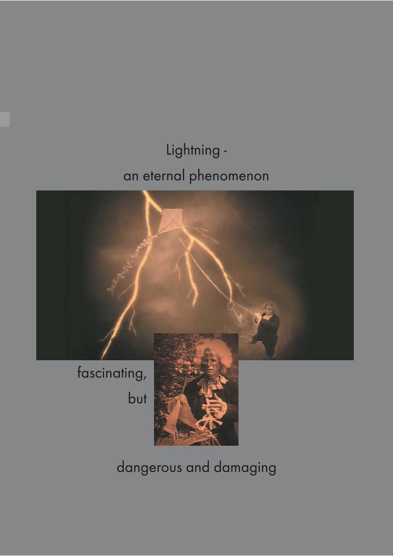
Lightning -
an eternal phenomenon
dangerous and damaging
fascinating,
but

HUBER+SUHNER lightning protectors 27
Def
initi
ons
and
term
spage
Product configuration 28Mounting and grounding options 28Most frequently used mounting and grounding options 29
Connector interfaces 30
RF power and DC ratings 33
Plating 33
HUBER+SUHNER SUCOPLATE® 33
Mounting holes (MH) 34
DEFINITIONS AND TERMS

HUBER+SUHNER lightning protectors28
PRODUCT CONFIGURATION
The design of HUBER+SUHNER lightning protectors al-lows for distinguishing between the «protected» (equip-ment) and «unprotected» (antenna) side.
Products with a feed-through design guarantee a lowcontact resistance due to its circumferential closedground connection.
antenna equipment
connector unprotected side connector protected side
bracket
screw
bulkhead
Mounting and grounding options
There are different mounting options available whichcan be used both for grounding and mounting pur-poses. Mounting and grounding/bonding of the pro-tectors can be done simultaneously, employing onemounting facility only or several facilities at differentplaces on the component.
All protectors featuring N and 7/16 DIN connectorsare waterproof and therefore can be installed outdoorpartially or completely. HUBER+SUHNER bulkheadmounting provides waterproof panel sealing.

HUBER+SUHNER lightning protectors 29
Def
initi
ons
and
term
s
Most frequently used mounting and grounding options
Bulkhead
Screw
Bracket
cable
cableorequipment
cable
cable orequipment

HUBER+SUHNER lightning protectors30
CONNECTOR INTERFACES
HUBER+SUHNER lightning protectors generally employ coaxial designs. For interconnection to any componentor system, the well-proven internationally specified coaxial interfaces are used.They conform to the following international standards:
Connector interface* Standards Coupling nut torque force
N IEC 60169-16, MIL-STD-348/304 0.68 Nm ... 1.13 Nm/6.0 ... 10.0 in-lbs
DIN 7/16 IEC 60169-4 25 Nm ... 30 Nm/221 ... 260 in-lbs
TNC IEC 60169-17, MIL-STD-348/313 46 Ncm ... 69 Ncm/4.1 ... 6.1 in-lbs
BNC IEC 60169-8, MIL-STD-348/301 7 Ncm ... 28 Ncm/0.6 ... 2.5 in-lbs
SMA IEC 60169-15, MIL-STD-348/310 0.8 Nm ... 1.1 Nm/7.1 ... 9.7 in-lbs
* illustrations on pages 31 - 32
For others refer to the HUBER+SUHNER Coaxial Connectors General Catalogue. It also includes the completeinterface dimensions. Selected direct cable entries are available as well.
Male connector (m)
«A male connector features the coupling nut ofthe coupling mechanism»
Female connector (f) «A female connector features the couplingmechanism complementary to the male connec-tor»

HUBER+SUHNER lightning protectors 31
Def
initi
ons
and
term
s
InterfaceStandard
Male connectorAbbreviation (m)
Female connectorAbbreviation (f)
7/16
IEC 60169-4
7/16 (m) 7/16 (f)
N
IEC 60169-16MIL-STD-348/304
N (m) N (f)
QN
Quick Lock Formula (QLF)
QN (m) QN (f)
TNC
IEC 60169-17MIL-STD-348/313
TNC (m) TNC (f)

HUBER+SUHNER lightning protectors32
InterfaceStandard
Male connectorAbbreviation (m)
Female connectorAbbreviation (f)
TNC (m) TNC (f)
BNC
IEC 60169-8MIL-STD-348/301
BNC (m) BNC (f)
SMA
IEC 60169-15MIL-STD-348/310
SMA (m) SMA (f)
F
F (f)

HUBER+SUHNER lightning protectors 33
Def
initi
ons
and
term
s
RF POWER AND DC RATINGS OF COAXIAL INTERFACES
(valid for coaxial interface only, reductions for several special-protectors solutions according to specification– e.g. DC injection, high-pass, high-power, standard gas capsule protectors limited by gas capsule, IM specifica-tions according to carrier definitions, etc.)
Interface RF power [kW] DC current [A]
for VSWR = 1, sea level and 40 °C
100 MHz 900 MHz 1900 MHz
N 4.6 1.0 0.6 6
7/16 DIN 10.5 3.0 2.0 13
PLATING
HUBER+SUHNER lightning protectors feature well-proven platings equivalent to HUBER+SUHNER RF coaxialconnectors for all metal parts to ensure low and stable contact resistances, good RF conductivity, low intermodula-tion, high corrosion resistivity and attractive appearance.
Standard platings Thickness
Contacts Housings
Silver (Ag) 3.0 μm/120 μin 3.0 μm/120 μin
Gold (Au) 1.3 μm/50 μin 0.8 μm/30 μin
SUCOPLATE® 0.5 μm/20 μin over 2.0 mm/80 μin Ag 2.0 μm/80 μin
excellent electrical conductivitynon-magneticnegligible passive intermodulation products equalto silverconsistent plating thickness distributionhigh abrasion resistancelow surface frictionexcellent adhesion and ductilitytarnish-resistanthigh corrosion resistancenon-allergenic plating
•••
•••••••
For more detailed informa-
tion refer to the brochure
"SUHNER Surface Platings
for RF Components".
HUBER+SUHNER SUCOPLATE® high-quality surface plating for RF components
SUCOPLATE® is a special tri-metallic HUBER+SUHNER plating. For more than 20 years it has been usedto protect RF components in both indoor and outdoor applications. SUCOPLATE® gives the majority ofHUBER+SUHNER products their proven properties and their bright-metal appearance. SUCOPLATE® providesnot only an attractive finish but also the following important properties for RF components:

HUBER+SUHNER lightning protectors34
MOUNTING HOLES
Mounting holes (MH) used with bulkhead mounted protectors (all dimensions in mm)
MH 2 MH 3 MH 4
MH 12 MH 20 MH 24
MH 25 MH 35 MH 38
MH 50 MH 69 MH 70

HUBER+SUHNER lightning protectors 35
Def
initi
ons
and
term
s
MH 71 MH 72 MH 73
MH 74 MH 80 MH 101
MH 110 MH 116 MH 118
MH 119
Mounting holes (MH, all dimensions in mm)

HUBER+SUHNER lightning protectors36
Follow our recommendation -
for your valuable electronic equipment
HUBER+SUHNER lightning protectors
HUBER+SUHNER lightning protectors 37
Qui
ck s
elec
tion
page
Basic application scheme 38Installation recommendation 38Recommended HUBER+SUHNER protector group 38
General selection guidance 40Basic properties 40Map of protector series 43
Quick selection lists 44Quarter-wave protectors 44 Standard quarter-wave protectors 44 Quarter-wave protectors with high-pass filter 45Gas capsule protectors 46 Standard gas capsule protectors 46 Slim Line protectors 47 Standard high-power/low-IM protectors 48 High-power/low-IM with high-pass filter and DC inj. 49 Fine protectors 50
QUICK SELECTION GUIDE

HUBER+SUHNER lightning protectors38
BASIC APPLICATION SCHEME
Select your basic application purpose from the gen-eral scheme of a radio transmitter configuration formobile and fixed systems, but also general wirelessapplications. Rooftop installations follow similar con-siderations.All protectors provide protection against direct andindirect interferences of lightning, but also NEMP (Nu-clear Electromagnetic Pulse) and other surge signals.Miniature surge protectors for indoor protection ofelectronic equipment are not shown here – refer to se-ries 3404 (page 78).
Installation recommendation
Ideally mounted directly on a wall feed-throughsheet metal which is properly connected to thebonding/grounding system to establish a protec-tion zone LPZ1 or higher according to IEC 61312-1.Protection unit – stub or gas capsule – to be ar-ranged outside of the protected room not to causeany interferences by any surge current conductedto ground (all N and 7/16 DIN products are wa-terproof).Integrated in a bonding bar right behind the wallas an alternative.
•
•
•
GPS
Recommended HUBER+SUHNER protector group
Quick selection page Full range page
1. Quarter-wave protectors series 3400 + 3407 44, 45 54, 86
2. Gas capsule protectors Series 3401/02 + 3408 46 62, 68, 92
3. Fine protectors series 3403 50 74
4. Slim line gas capsule protectors series 3406 47 82
5. High-power/low IM series 3409 + 3410 (DC injection) 48, 49 94, 100
6. SEMPER™ -- 113
7. Signal/data line protectors series 3414 -- 104
8. High voltage DC block series 9077 -- 120
For more familiarity with our protection principles and configuration definitions refer to the «General SelectionGuidance» on the next pages.
Our grounding kit product range has been placed in the catalogue on pages 139 to 140.

HUBER+SUHNER lightning protectors 39
Qui
ck s
elec
tion
1
23
5
2
5
7
Jumper Cables*
Power Splitters*
SUCOFEED Cables*
Grounding Kits*
QUICK-FIT Connectors*
4
*You will find all necessary informationabout these products in our QUICK-FIT con-nectors (648137) and POWER SPLITTERS(23041087) catalogues.
47
6
8

HUBER+SUHNER lightning protectors40
GENERAL SELECTION GUIDANCE
Basic properties of available HUBER+SUHNER protection principles
Detailed series data: 3400 page 54 3407 page 86
Detailed series data: 3401 page 62 3402 page 68 3408 page 92
broadband and narrowband units availablemaintenance-freehighest surge current handling capability– N: 50 kA (8/20 μs test pulse)– 7/16: 100 kA (8/20 μs test pulse)lowest residual surge pulse voltage and energybest IM performanceDC/AC powering via coax not possibleproducts with integrated high-pass filter with evenfurther reduced residual pulse (series 3407) avail-able
•••
••••
HUBER+SUHNER quarter-wave protectors (series 3400, 3407) Quick selection page 44, 45
HUBER+SUHNER gas capsule protectors (series 3401, 3402, 3408) Quick selection page 46
broadband operation– series 3401: DC-1 GHz– series 3402: DC-2.5 GHzDC/AC powering via coax cable (not 3408)surge current handling capability 30 kA once and20 kA multiplegas capsule replaceableeasy maintenancegas capsule has to be selected according to RFpowerproducts with integrated high-pass filter and DCinjection offering a further reduced residual pulse(series 3408) availableDC injection port can be added
•
••
•••
•
•

HUBER+SUHNER lightning protectors 41
Qui
ck s
elec
tion
HUBER+SUHNER Fine Protectors (series 3403) Quick selection page 50
HUBER+SUHNER Slim Line gas capsule protectors (series 3406) Quick selection page 47
broadband operationessentially increased protection compared to stand-ard gas capsule protectorsDC/AC powering via coax possible (bypassfeature)surge current handling capability 30 kA once and20 kA multipleresidual surge pulse energy reduced by about factor 100 compared to standard gas capsule protector
••
•
•
•
wide-band operation DC to 5.8 GHzsurge current handling 10 kA once and 5 kA multiplegas capsule fix installedslim inline designDC/AC powering via coaxial cablebulkhead mounting/grounding
••
••••
Detailed series data: 3403 on page 74
Detailed series data: 3406 on page 82

HUBER+SUHNER lightning protectors42
HUBER+SUHNER high-power/low IM gas capsule protectors (series 3409, 3410) Quick selection page 48, 49
broadband and narrowband units availablegas capsule protector working independent oftransmitted RF powerDC/AC powering via coaxial cablesurge current handling capability 30 kA once and20 kA multiplelowest available residual pulse voltage and energycompared to other high-power gas capsule protec-torslowest IM for any gas capsule protector availablein the marketproducts with integrated high-pass filter and DCinjection offering a further reduced residual pulse(series 3410) availableDC injection port can be added
••
••
•
•
•
•
HUBER+SUHNER data-line protectors (series 3414)
data line coarse and fine protection solution forhigh speed data transmission on STP / UTP linesdifferent DLP units available up to Class D (CAT5)different interconnections availablefor high speed Ethernet data transmission unitsavailable for indoor and outdoor applications upto waterproof IP rating IP68rugged metal housingmaintenance freePoE «Power over Ethernet» acc. IEEE 802.3.af forhigh speed Ethernet data transmission equipment
•
••••
•••
Detailed series data: 3409 on page 94 3410 on page 100
Detailed series data: 3414 on page 104

HUBER+SUHNER lightning protectors 43
Qui
ck s
elec
tion
Map of protector series vs. frequency range (protection solutions)
The chart below shows our product series and technologies with their typical operation frequency range. For spe-cific operating frequency ranges please refer to the detailed product specification.
Frequency range in MHz
Quarter-wave technology
Gas capsule technology
series 3400
series 3407
series 3401
series 3402
series 3408
series 3403
series 3406
series 3409
series 3410
1 10 100 1000 10000 100000
DC/AC powering via coaxial cable possible
Products available within this frequency range but with limited
bandwidth (according to shown product detail specification)

HUBER+SUHNER lightning protectors44
All mounting holes are shown on pages 34 – 35.
QUICK SELECTION LISTS
Quarter-wave protectors
Standard quarter-wave protectors series 3400
Important
Standard quarter-wave protectors can also be installed reversely («backwards») without any impact onperformance.All products feature low PIM design.
Applications and product range
System System frequency range (MHz)
Connectors Mounting/grounding
Type Further product info
Unprotected/protected sideIf bulkhead mount version, side of bulk-head marked «b».
MH - hole for «b»M - screwbrk - bracket Page
TETRA, TETRAPOL 380-512
N(m)-N(f), b MH74, M8, brk 3400.17.0388 567/16(f)-7/16(f), b MH74, M8, brk 3400.41.0196 567/16(m)-7/16(f), b MH74, M8, brk 3400.41.0203 56
AMPS/NADC,TACS,TETRA,GSMGPSDCS, PCS, DECTUMTS
824-894860-9601565-15861710-19001885-2200
N(m)-N(f) M8, brk 3400.17.0377 57N(m)-N(f), b MH110, M8 3400.17.0420 577/16(m)-7/16(f) M8, brk 3400.41.0204 577/16(f)-7/16(f) M8, brk 3400.41.0216 577/16(m)-7/16(f), b MH74, M8, brk 3400.41.0217 577/16(m)-7/16(f), b MH110, M8 3400.41.0241 57
GPS 1565 - 1586N(m)-N(f), b MH12, M8 3400.17.0280 59
WLL/WLAN
2400-36002300-27003400-42002000-6000
N(m)-N(f), b MH50, M8 3400.17.0247 60TNC-R(f)-TNC-R(m), b MH25 3400.99.0005 60N(f)-N(f), b MH69 3400.17.0189 60N(m)-N(f) M8 3400.17.0410 60
Microwave Radio 6000-18000N(f)-N(f), b MH69 3400.17.0380 60
•
•

HUBER+SUHNER lightning protectors 45
All mounting holes are shown on pages 34 – 35.
Qui
ck s
elec
tion
Quarter-wave protectors with integrated high-pass filter series 3407
Important
Quarter-wave protectors with integrated high-pass filter cannot be installed reversely («backwards») withoutany impact on performance.All products feature low PIM design.
Applications and product range
System System frequency range (MHz)
Connectors Mounting/grounding
Type Further product info
Unprotected/protected sideIf bulkhead mount version, side of bulk-head marked «b».
MH - hole for «b»M - screwbrk - bracket Page
ILS 74/180N(f)-N(f), b MH74, M8, brk 3407.17.0022 88
PMR, Paging 146-174N(m)-N(f), b MH12, M8 3407.17.0054 88
VHF Broadcasting 174-280N(m)-N(f), b MH72, M8, brk 3407.17.0026 88
TETRA, TETRAPOL 380-5127/16(m)-7/16(f) M8, brk 3407.41.0038 89
AMPS/NADCand TACS (N+E)and TETRAand GSM,IMT-2000/UMTS
824-894860-949870-925880-9601885-2500
N(f)-N(f), b MH110, M6 3407.17.0067 90N(m)-N(f), b MH110, M6 3407.17.0068 907/16(m)-7/16(f), b MH110, M6 3407.41.0039 907/16(f)-7/16(f), b MH110, M6 3407.41.0042 90
•
•

HUBER+SUHNER lightning protectors46
All mounting holes are shown on pages 34 – 35.
Gas capsule protectors
Standard gas capsule protectors 3401/3402 (gas capsule normally to be selected and ordered separately – refer to page 124)
Important
Standard gas capsule protectors can also be installed reversely («backwards») without any impact onperformance.
Applications and product range
System System frequency range (MHz)
Connectors Mounting/grounding
Type Further product info
Unprotected/protected sideIf bulkhead mount version, side of bulk-head marked «b».
MH - hole for «b»M - screwbrk - bracket Page
PMR, Pagingand TETRAand NMT 450AMPS/NADCand TACS (N+E)and TETRAand GSMand Point-to-PointMW-Radios IF
146-174380-512453-468824-894860-949870-925880-960
up to 1000
N(f)-SMA(f), b MH12 3401.00.0022 64BNC(f)-BNC(f), b MH12 3401.01.A 64BNC(m)-BNC(f), b MH12 3401.01.C 64N(f)-N(f), b MH12, M8 3401.17.0033 64N(f)-N(f), b MH12 3401.17.A 64N(m)-N(f), b MH12 3401.17.C 64TNC(f)-TNC(f), b MH12 3401.26.A 64TNC(m)-TNC(f), b MH12 3401.26.C 64
GPSand DCS 1800and PCS 1900and DECTand IMT-2000/UMTSand WLL/WLAN
1565-15861710-18801850-19901880-1900
1885-22002300-2500
7/16(f)-N(f), b MH12, M8 3402.00.0032 70N(m)-N(f), b MH12, M8 3402.17.0043 70N(f)-N(f), b MH12, M8 3402.17.0044 70N(f)-N(f), b MH25 3402.17.A 70N(m)-N(f), b MH25 3402.17.C 707/16(m)-7/16(f), b MH74, M8 3402.41.0037 707/16(f)-7/16(f), b MH74, M8 3402.41.0038 707/16(f)-7/16(f), b MH72 3402.41.A 70N(f)-N(f) MH25 3402.99.0003 70
•

HUBER+SUHNER lightning protectors 47
All mounting holes are shown on pages 34 – 35.
Qui
ck s
elec
tion
System System frequency range (MHz)
Connectors Mounting/grounding
Type Further product info
Unprotected/protected sideIf bulkhead mount version, side of bulk-head marked «b».
MH - hole for «b»M - screwbrk - bracket Page
PMR, Pagingand TETRAand NMT 450AMPS/NADCand TACS(N+E)and TETRAand GSMand Point-to-PointMW-Radios IFGPSand DCS 1800and PCS 1900and DECTand IMT-2000/UMTSand WLL/WLANand ISM
146–174380–512453–468824–894860–949870–925880–960
up to 10001565–15861710–18801850–19901880–1900
1885–22002300–25005200–5800
BNC(m)-BNC(f), b MH4 3406.01.0003 84N(f)-N(f), b MH24 3406.17.0009 84N(m)-N(f), b MH24 3406.17.0012 84SMA(F)-SMA(f), b MH3 3406.19.0003 84SMA(m)-SMA(f), b MH3 3406.19.0004 84TNC(m)-TNC(f), b MH4 3406.26.0004 84
Slim line protectors series 3406
Applications and product range

HUBER+SUHNER lightning protectors48
All mounting holes are shown on pages 34 – 35.
Standard high-power/low-IM gas capsule protectors series 3409 (gas capsule included)
Important
Standard high-power/low-IM protectors can also be installed reversely («backwards») without any impact onperformance.All products feature low PIM design.
Applications and product range
System System frequency range (MHz)
Connectors Mounting/grounding
Type Further product info
Unprotected/protected sideIf bulkhead mount version, side of bulk-head marked "b".
MH - hole for "b"M - screwbrk - bracket Page
TETRA, TETRAPOL 380-512N(m)-N(f), b MH74, M8, brk 3409.17.0032-EX 967/16(m)-7/16(f) M8, brk 3409.41.0054-EX 96
AMPS/NADC,TACS,TETRA,GSMGPSDCS, PCS, DECTUMTSWLL/WLAN
824-894860-9601565-15861710-19001885-22002300-2500
N(f)-N(f), b MH74, M8, brk 3409.17.0031-EX 97N(m)-N(f) M8, brk 3409.17.0027-EX 977/16(f)-7/16(f) M8, brk 3409.41.0051-EX 977/16(f)-7/16(f), b MH74, M8, brk 3409.41.0052-EX 977/16(m)-7/16(f) M8, brk 3409.41.0044-EX 977/16(m)-7/16(f), b MH74, M8, brk 3409.41.0053-EX 97
•
•

HUBER+SUHNER lightning protectors 49
All mounting holes are shown on pages 34 – 35.
Qui
ck s
elec
tion
High-power/low-IM gas capsule protectors with integrated high-pass filter and DC injection series 3410
Important
High-power/low-IM protectors with integrated high-pass filter cannot be installed reversely («backwards»)without any impact on performance.All products feature low PIM design.
Applications and product range
System System frequency range (MHz)
Connectors Mounting/grounding
Type Further product info
Unprotected/protected sideIf bulkhead mount version, side of bulk-head marked «b».
MH - hole for «b»M - screwbrk - bracket Page
TETRA, TETRAPOL 380-5127/16(m)-7/16(f)* M8, brk 3410.41.0009-EX 102
AMPS/NADCand TACS(N+E)and TETRAand GSMDCS 1800and PCS 1900and DECTIMT-2000/UMTSWLL/WLAN
824–894860–949870–925880–9601710–18801850-19901880-22002500
N(f)-N(m)* M8, brk 3410.17.0012-EX 1037/16(m)-7/16(f)* M8, brk 3410.41.0017-EX 1037/16(f)-7/16(f)** M8, brk 3410.41.0020 103
* DC injection port TNC (f)
** DC injection port SMB (f)
•
•

HUBER+SUHNER lightning protectors50
All mounting holes are shown on pages 34 – 35.
Fine protectors series 3403 (gas capsule included)
Important
Fine protectors with integrated high-pass filter cannot be installed reversely («backwards») without any impacton performance.All listed Fine Protectors are multi-band products (650-2500 MHz).
Applications and product range
System System frequency range (MHz)
Connectors Mounting/grounding
Type Further product info
Unprotected/protected sideIf bulkhead mount version, side of bulk-head marked «b».
MH - hole for «b»M - screwbrk - bracket Page
AMPS/NADCand TACS(N+E)and TETRAand GSMDCS 1800and PCS 1900and DECTIMT-2000/UMTSWLL/WLAN
824–894860–949870–925880–9601710–18801850–19901880–19002400–22002500
N(f)-N(f) 2xM4 3403.17.0042 76N(m)-N(f), b MH119, 2xM4 3403.17.0049 76N(f)-N(f), b MH119, 2xM4 3403.17.0050 76
•
•

HUBER+SUHNER lightning protectors 51
Qui
ck s
elec
tion
SPACE FOR YOUR NOTES

HUBER+SUHNER lightning protectors52
With HUBER+SUHNER you select
the original and innovative
protection solution supplier -
relax and rely on our competence!

HUBER+SUHNER lightning protectors 53
Prod
ucts
Page
Series detail information
Series 3400Quarter-wave lightning protectors 54
Series 3401Gas capsule lightning protectors up to 1.0 GHz 62
Series 3402Gas capsule lightning protectors up to 2.5 GHz 68
Series 3403Fine protectors 74
Series 3404Miniature gas capsule protectors 78
Series 3406Slim Line gas capsule protectors 82
Series 3407Quarter-wave lightning protectors with integratedhigh-pass filter 86
Series 3408Gas capsule lightning protectors with integratedhigh-pass filter 92
Series 3409High-power/low-IM gas capsule lightning protectors 94
Series 3410High-power/low-IM gas capsule lightning protectorswith integrated high-pass filter and DC injection 100
Series 3414Data line protectors 104
Special products 112- SEMPER™ self-extinguishing gas capsule protectors 113- DC injectors 118- High voltage DC-blocks 120
LIGHTNING PROTECTION PRODUCTS

HUBER+SUHNER lightning protectors54
SERIES 3400QUARTER-WAVE LIGHTNING PROTECTORS
Description
Features
broadbandavailable within 60 MHz to 18 GHz max. (N, SMA)best PIM performancehighest current-handling capability up to 100 kA max.maintenance-free
Specification
Electrical data Requirements
RF:
Impedance
Frequency rangeaccording to shown product specification, basic availability rangefrom 60 MHz to frequency limit of coaxial interface
RL 20 dB min.
IL
PIMaccording to product detail specification (data sheet)(specified products –150 dBc max.)
RF power transmissionrefer to data in section Definitions and Terms «RF power and DC ratings» andproduct detail specification (data sheet)
Protection:
Surge current handling capabilityN: 50 kA, DIN 7/16: 50 to 100 kA, (8/20 μs test pulse)N: 25 kA, DIN 7/16: 50 kA, (10/350 μs test pulse) refer to single productdata sheet
Residual pulse voltage and energy for typical values refer to the following diagram
•••••
HUBER+SUHNER quarter-wave lightning protectors of-fer the best lightning protection available in the market,as they form a short for surge signals basically. Theyhave been established as a worldwide industry stand-ard by HUBER+SUHNER as the original manufacturer.The products are maintenance-free and feature thebest protection performance with both the highestsurge current handling capability and the lowest re-sidual pulse amplitude. Also, their RF performance is
superior to other designs, including passive intermodu-lation.HUBER+SUHNER lightning protectors series 3400 of-fer a large variety of products and can be adapted toany application. Besides connectorization and mount-ing principle, the frequency range has to be selectedproperly due to their generally limited bandwidth.

HUBER+SUHNER lightning protectors 55
Prod
ucts
Typical residual pulse for series 3400 (for GSM band)(test pulse acc. to IEC 61000-4-51.2/50 μs 4 kV; 8/20 μs 2 kA):
Residual pulse voltage: 7 VResidual pulse energy: 5 μJ
Mechanical data Requirements
Coupling nut torque force according to IEC/MIL (refer to page 30)
Durability (matings) 500 min.
Bulkhead mounting torque force:Mounting hole diameter19 mm/ 3/4“ max.larger than 19 mm
20 Nm (14.7 ft-lb) min. / 25 Nm (18.4 ft-lb) max.35 Nm (25.8 ft-lb) min. / 44 Nm (32.3 ft-lb) max.
Environmental data Requirements/test conditions
Operation temperature range – 40 °C...+ 85 °C/ – 40 °F...+ 185 °F
Waterproof degree (IEC 60529) IP 65 min., according to shown product specification, data refer to the coupled state
Temperature shock MIL-STD-202, Meth. 107, Cond. B
Moisture resistance MIL-STD-202, Meth. 106
Vibration MIL-STD-202, Meth. 204, Cond. D
The product is designed to meet the cited test procedures. Any additional or different requirements arising from specific
applications or environmental conditions not covered by the test specifications mentioned above are subject to request and
need to be confirmed by the single product detail specification.
We recommend additional taping for long term outdoor applications in any case.
Material data
Component part Standard Material Plating
Housings QQ-B-626 brass SUCOPLATE®
Male contacts QQ-B-626 brass gold or silver plating
Female contacts QQ-C530 CuBe2 gold or silver plating
Insulators ASTM-D-1457 PTFE
Gaskets ASTM-E-1418 PS 1 elastomer rubber
-4
-2
0
2
4
6
8
-5 0 5 10 15 20 25 30 35 40 45 50
Time [μs]
Puls
e Vo
ltage
[V]

HUBER+SUHNER lightning protectors56
All mounting holes are shown on page 34 – 35.
SERIES 3400
Frequency range 380 MHz to 512 MHz
Type Frequencyrange (MHz)
Connectors Mounting/grounding
RLmin.
ILmax.
Water-proof
Weight Figure
Unprotected/protected side*If bulkhead mount version,side of bulkhead marked «b».
MH - hole for «b»M - screwbrk - bracket
3400.17.0388 380-512 N(m)-N(f), b MH74,M8,brk 20 dB 0.1 dB IP 65 325 g Fig. 13400.41.0196 380-512 7/16(f)-7/16(f), b MH74,M8,brk 20 dB 0.1 dB IP 65 354 g Fig. 23400.41.0203 380-512 7/16(m)-7/16(f), b MH74,M8,brk 20 dB 0.1 dB IP 67 580 g Fig. 3
* recommendation only, reverse installation possible without any impact on performance
Fig.1 Fig. 2 Fig. 3
All dimensions in mm

HUBER+SUHNER lightning protectors 57
All mounting holes are shown on pages 34 – 35.
Prod
ucts
SERIES 3400
Broadband, frequency range 800 MHz to 2500 MHz
Type Frequencyrange (MHz)
Connectors Mounting/grounding
RLmin.
ILmax.
Water-proof
Weight Figure
Unprotected/protected side*If bulkhead mount version,side of bulkhead marked «b».
MH - hole for «b»M - screwbrk - bracket
3400.17.0377 806-2500 N(m)-N(f) M8, brk 20.8 dB 0.15 dB IP 65 400 g Fig. 1806-960 26.0 dB1710-2500 26.0 dB
3400.17.0420** 806-2200 N(m)-N(f), b MH110, M8 20.8 dB 0.10 dB IP68 480 g Fig. 2824-960 23.0 dB1710-2200 23.0 dB
3400.41.0216 806-2500 7/16(f)-7/16(f) M8, brk 20.8 dB 0.15 dB IP 65 431 g Fig. 3806-960 26.0 dB1710-2500 26.0 dB
3400.41.0204 806-2500 7/16(m)-7/16(f) M8, brk 20.8 dB 0.15 dB IP 65 487 g Fig. 4806-960 26.0 dB1710-2500 26.0 dB
3400.41.0217 806-2500 7/16(m)-7/16(f), b MH74,M8,brk 20.8 dB 0.15 dB IP 65 515 g Fig. 5806-960 26.0 dB1710-2500 26.0 dB
3400.41.0241** 806-2200 7/16(m)-7/16(f), b MH110, M8 20.8 dB 0.10 dB IP68 480 g Fig. 6824-960 23.0 dB1710-2200 23.0 dB
* recommendation only, reverse installation possible without any impact on performance
** inline design

HUBER+SUHNER lightning protectors58
All mounting holes are shown on page 34 – 35.
Fig.1 Fig. 3
Fig. 4 Fig. 5
Fig. 2
Fig. 6
All dimensions in mm

HUBER+SUHNER lightning protectors 59
All mounting holes are shown on pages 34 – 35.
Prod
ucts
SERIES 3400
Frequency range 1000 MHz to 1700 MHz
Type Frequencyrange (MHz)
Connectors Mounting/grounding
RLmin.
ILmax.
Water-proof
Weight Figure
Unprotected/protected side* Ifbulkhead mount version, side ofbulkhead marked «b».
MH - hole for «b»M - screwbrk - bracket
3400.17.0280 1565–1586 N(m)-N(f), b MH12, M8 20 dB 0.1 dB IP 65 270 g Fig. 1
* recommendation only, reverse installation possible without any impact on performance
All dimensions in mm
Fig. 1

HUBER+SUHNER lightning protectors60
All mounting holes are shown on page 34 – 35.
SERIES 3400
Frequency range 2000 MHz to 18000 MHz
Type Frequencyrange (MHz)
Connectors Mounting/grounding
RLmin.
ILmax.
Water-proof
Weight Figure
Unprotected/protected side* Ifbulkhead mount version, side ofbulkhead marked «b».
MH - hole for «b»M - screwbrk - bracket
3400.17.0189 3400–4200 N(f)-N(f),b MH69 19 dB 0.10 dB IP65 200 g Fig. 13400.17.0247 2400–3600 N(m)-N(f), b MH50, M8 20 dB 0.15 dB IP66 290 g Fig. 2
3400.17.03806000–18000
N(f)-N(f), b MH69 20 dB 0.30 db IP65 225 g Fig. 3
3400.17.0410 2000–6000 N(m)-N(f) M8 20 dB 0.20 dB IP65 290 g Fig. 4
3400.99.0005 2300–2700 TNC-R(f)-TNC-R(m), b MH25 20 dB 0.15 dB IP20 120 g Fig. 5
* recommendation only, reverse installation possible without any impact on performance

HUBER+SUHNER lightning protectors 61
All mounting holes are shown on pages 34 – 35.
Prod
ucts
Fig. 2
Fig. 1 Fig. 2 Fig. 3
Fig. 4
All dimensions in mm

HUBER+SUHNER lightning protectors62
HUBER+SUHNER gas capsule protectors make thebest of the traditional spark gap protection principlefor general applications in electronics and adapt itperfectly to RF coaxial line applications. At their heartare specially designed gas capsules. The availableproduct range of capsules enables a selection accord-ing to the RF transmission power with an optimum pro-tection performance. A very important feature of the gas capsule protectorsis the possibility to DC/AC power outdoor equipmentvia coaxial cable.
Series 3401 products can be used broadband fromDC to 1000 MHz.They are generally designed as coaxial feed-throughswhich allow the customer to build up a protected areaaccording to the recommended and well-proven pro-tection zone principle of IEC 61312-1.HUBER+SUHNER gas capsule protectors are de-signed such that the gas capsules can be easily ex-changed for new operation conditions or replaced inthe case of a necessary service.
SERIES 3401GAS CAPSULE LIGHTNING PROTECTORS UP TO 1 GHZ
Description
Features
broadband DC to 1 GHzDC transmissiongas capsule replaceableeasy maintenanceSEMPER™ self-extinguishing functionality (optional, see page 113)
Specifications
Electrical data Requirements
RF:
Impedance
Frequency range DC – 1000 MHz
RL* 20 dB min.
IL* 0.2 dB max.
RF power transmission according to selected gas capsule – refer to page 133
Protection:
Surge current handling capability30 kA once and 20 kA multiple (8/20 μs test pulse)8 kA (10/350 μs test pulse)
Residual pulse voltage and energy for typical values refer to the following diagram
* with 230 V gas capsule (9071.99.0547)
•••••

HUBER+SUHNER Lightning Protectors 63
Prod
ucts
Typical residual pulse for series 3401*(test pulse acc. to IEC 61000-4-51.2/50 μs 4 kV; 8/20 μs 2 kA):
Residual pulse voltage: 650 VResidual pulse energy: 350 μJ
* with 230 V gas capsule (9071.99.0547)
Mechanical data Requirements
Coupling nut torque force according to IEC/MIL (refer to page 30)
Durability (matings) 500 min.
Bulkhead mounting torque force:Mounting hole diameter19 mm/ 3/4“ max.larger than 19 mm
20 Nm (14.7 ft-lb) min. / 25 Nm (18.4 ft-lb) max.35 Nm (25.8 ft-lb) min. / 44 Nm (32.3 ft-lb) max.
Environmental data Requirements/test conditions
Operation temperature range – 40 °C...+ 85 °C/ – 40 °F...+ 185 °F
Waterproof degree (IEC 60529) according to shown product specification, data refer to the coupled state
Temperature shock MIL-STD-202, Meth. 107, Cond. B
Moisture resistance MIL-STD-202, Meth. 106
Vibration MIL-STD-202, Meth. 204, Cond. D
The product is designed to meet the cited test procedures. Any additional or different requirements arising from specific
applications or environmental conditions not covered by the test specifications mentioned above are subject to request and need to be
confirmed by the single product detail specification.
We recommend additional taping for long term outdoor applications in any case.
Material data
Component part Standard Material Plating
Housings QQ-B-626 brass SUCOPLATE®
Male contacts QQ-B-626 brass gold or silver plating
Female contacts QQ-C-530 CuBe2 gold or silver plating
Insulators ASTM-D-1457 PTFE
Gaskets ASTM-E-1418 PS 1 elastomer rubber
-100
0
100
200
300
400
500
600
700
800
-50 0 50 100 150 200 250 300
Time [μs]
Puls
e Vo
ltage
[V]

HUBER+SUHNER lightning protectors64
All mounting holes are shown on pages 34 – 35.
SERIES 3401
(gas capsule normally to be selected and ordered separately – refer to page 130 - 133)
Type Frequency range (MHz)
Connectors Mounting/grounding
RLmin.
ILmax.
Water-proof
Weight Figure
Unprotected/protected side*If bulkhead mount version, sideof bulkhead marked «b».
MH - hole for «b»M - screwbrk - bracket
3401.00.0022 DC–1000 N(f)-SMA(f), b MH12 20 dB 0.2 dB IP 66 95 g Fig. 1
3401.01.A DC–300 BNC(f)-BNC(f), b MH12 26 dB 0.1 dB IP 20 75 g Fig. 2300–1000 19 dB 0.1 dB
3401.01.C DC–300 BNC(m)-BNC(f), b MH12 26 dB 0.1 dB IP 20 90 g Fig. 3300–1000 19 dB 0.1 dB
3401.17.0033 DC–1000 N(f)-N(f), b MH12, M8 20 dB 0.2 dB IP 65 230 g Fig. 43401.17.A DC–1000 N(f)-N(f), b MH12 26 dB 0.1 dB IP 65 87 g Fig. 53401.17.C DC–1000 N(m)-N(f), b MH12 26 dB 0.1 dB IP 65 90 g Fig. 6
3401.26.A DC–300 TNC(f)-TNC(f), b MH12 26 dB 0.1 dB IP 64 77 g Fig. 7300–1000 19 dB 0.1 dB
3401.26.C DC–300 TNC(m)-TNC(f), b MH12 26 dB 0.1 dB IP 20 90 g Fig. 8300–1000 19 dB 0.1 dB
* recommendation only, reverse installation possible without any impact on performance

HUBER+SUHNER Lightning Protectors 65
All mounting holes are shown on pages 34 – 35.
Prod
ucts
Fig. 1 Fig. 2 Fig. 3
Fig. 4 Fig. 5 Fig. 6
Fig. 7 Fig. 8
All dimensions in mm

HUBER+SUHNER lightning protectors66
All mounting holes are shown on pages 34 – 35.
SERIES 3401
(gas capsule normally to be selected and ordered separately – refer to page 130 - 133)
Type Frequency range (MHz)
Connectors Mounting/grounding
RLmin.
ILmax.
Water-proof
Weight Figure
Unprotected/protected side*If bulkhead mount version,side of bulkhead marked «b».
MH - hole for «b»M - screwbrk - bracket
3401.02.A DC–400 BNC(f)-BNC(f), b MH 12 20 dB 0.1 dB IP 20 79 g Fig. 1400-1000 15 dB 0.2 dB
3401.18.A DC-500 N(f)-N(f), b MH12 20.8 dB 0.1 dB IP 65 92 g Fig. 2
3401.99.0020** DC-1000 F(f)-F(f), b MH 12 – 0.2 dB IP 65 73 g Fig. 3
* recommendation only, reverse installation possible without any impact on performance
** gas capsule included (90 V, 9071.99.0547)
All dimensions in mm
Fig. 1 Fig. 2 Fig. 3
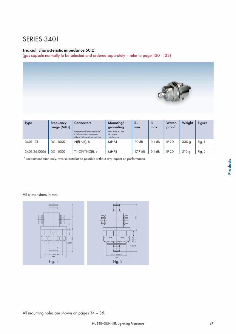
HUBER+SUHNER Lightning Protectors 67
All mounting holes are shown on pages 34 – 35.
Prod
ucts
SERIES 3401
(gas capsule normally to be selected and ordered separately – refer to page 130 - 133)
Type Frequency range (MHz)
Connectors Mounting/grounding
RLmin.
ILmax.
Water- proof
Weight Figure
Unprotected/protected side*If bulkhead mount version,side of bulkhead marked «b».
MH - hole for «b»M - screwbrk - bracket
3401.17.L DC–1000 N(f)-N(f), b MH74 20 dB 0.1 dB IP 20 330 g Fig. 1
3401.26.0006 DC–1000 TNC(f)-TNC(f), b MH74 17.7 dB 0.1 dB IP 20 310 g Fig. 2
* recommendation only, reverse installation possible without any impact on performance
All dimensions in mm
Fig. 1 Fig. 2

HUBER+SUHNER lightning protectors68
HUBER+SUHNER gas capsule protectors make thebest of the traditional spark gap protection principlefor general applications in electronics and adapt itperfectly to RF coaxial line applications.At their heart are specially designed gas capsules. Theavailable product range of capsules enables a selec-tion according to the RF transmission power with anoptimum protection performance. A very important feature of the gas capsule protectorsis the possibility to DC/AC power outdoor equipmentvia coaxial cable.
Series 3402 products can be used broadband fromDC to 2 GHz or even higher.They are generally designed as coaxial feed-throughswhich allow the customer to build up a protected areaaccording to the recommended and well-proven pro-tection zone principle of IEC 61312-1.HUBER+SUHNER gas capsule protectors are de-signed such that the gas capsules can be easily ex-changed for new operation conditions or replaced inthe case of a necessary service.
SERIES 3402GAS CAPSULE LIGHTNING PROTECTORS UP TO 2.5 GHZ
Description
Features
broadband DC to 2.5 GHzDC transmissiongas capsule replaceableeasy maintenanceSEMPER™ self-extinguishing functionality (optional, see page 113)
Specifications
Electrical data Requirements
RF:
Impedance
Frequency rangeDC – 2.5 GHz(some types different according to shown specification, but 2 GHz min.)
RL* 20 dB min. (exception F connectors)
IL* 0.2 dB max. (exception F connectors)
RF power transmission according to selected gas capsule – refer to page 133
Protection:
Surge current handling capability30 kA once and 20 kA multiple (8/20 μs test pulse)8 kA (10/350 μs test pulse)
Residual pulse voltage and energy for typical values refer to the following diagram
* with 230 V gas capsule (9071.99.0547)
•••••

HUBER+SUHNER lightning protectors 69
Prod
ucts
Typical residual pulse for series 3402*(test pulse acc. to IEC 61000-4-51.2/50 μs 4 kV; 8/20 μs 2 kA):
Residual pulse voltage: 650 VResidual pulse energy: 350 μJ
* with 230 V gas capsule (9071.77.0547)
Mechanical data Requirements
Coupling nut torque force according to IEC/MIL (refer to page 30)
Durability (matings) 500 min.
Bulkhead mounting torque force:Mounting hole diameter19 mm/ 3/4 " max.larger than 19 mm
20 Nm (14.7 ft-lb) min. / 25 Nm (18.4 ft-lb) max.35 Nm (25.8 ft-lb) min. / 44 Nm (32.3 ft-lb) max.
Environmental data Requirements/test conditions
Operation temperature range – 40 °C...+ 85 °C/ – 40 °F...+ 185 °F
Waterproof degree (IEC 60529) according to shown product specification, data refer to the coupled state
Temperature shock MIL-STD-202, Meth. 107, Cond. B
Moisture resistance MIL-STD-202, Meth. 106
Vibration MIL-STD-202, Meth. 204, Cond. D
The product is designed to meet the cited test procedures. Any additional or different requirements arising from specific
applications or environmental conditions not covered by the test specifications mentioned above are subject to request and need to be
confirmed by the single product detail specification.
We recommend additional taping for long term outdoor applications in any case.
Material data
Component part Standard Material Plating
Housings QQ-B-626 brass SUCOPLATE®
Male contacts QQ-B-626 brass gold or silver plating
Female contacts QQ-C-530 CuBe2 gold or silver plating
Insulators ASTM-D-1457 PTFE
Gaskets ASTM-E-1418 PS 1 elastomer rubber
-100
0
100
200
300
400
500
600
700
800
-50 0 50 100 150 200 250 300
Time [μs]
Puls
e Vo
ltage
[V]

HUBER+SUHNER lightning protectors70
All mounting holes are shown on pages 34 – 35.
SERIES 3402
(gas capsule normally to be selected and ordered separately – refer to page 130 - 133)
Type Frequency range (MHz)
Connectors Mounting/grounding
RLmin.
ILmax.
Water-proof
Weight Figure
Unprotected/protected side*If bulkhead mount version,side of bulkhead marked «b».
MH - hole for «b»M - screwbrk - bracket
3402.00.0032 DC–2000 7/16(f)-N(f), b MH12, M8 20 dB 0.2 dB IP 65 190 g Fig. 1
3402.17.0043 DC–2500 N(m)-N(f), b MH12, M8 20 dB 0.2 dB IP 65 230 g Fig. 23402.17.0044 DC–2500 N(f)-N(f), b MH12, M8 20 dB 0.2 dB IP 65 230 g Fig. 33402.17.A DC–2500 N(f)-N(f), b MH25 20 dB 0.2 dB IP 65 126 g Fig. 43402.17.C DC–2500 N(m)-N(f), b MH25 20 dB 0.2 dB IP 65 155 g Fig. 5
3402.41.0037 DC–2500 7/16(m)-7/16(f), b MH74, M8 20 dB 0.2 dB IP 65 450 g Fig. 63402.41.0038 DC–2500 7/16(f)-7/16(f), b MH74, M8 20 dB 0.2 dB IP 65 450 g Fig. 73402.41.A DC–2500 7/16(f)-7/16(f), b MH72 20 dB 0.2 dB IP 65 387 g Fig. 8
3402.99.0003 DC–2500 N-R(f)-N-R(f)** MH25 20 dB 0.2 dB IP 65 126 g Fig. 9
* recommendation only, reverse installation possible without any impact performance
** reverse interface (inner conductor pin, outer conductor as standard N(f))

HUBER+SUHNER lightning protectors 71
All mounting holes are shown on pages 34 – 35.
Prod
ucts
Fig. 7 Fig. 8 Fig. 9
Fig. 1 Fig. 2 Fig. 3
Fig. 4 Fig. 5 Fig. 6
All dimensions in mm

HUBER+SUHNER lightning protectors72
All mounting holes are shown on pages 34 – 35.
SERIES 3402
(gas capsule normally to be selected and ordered separately – refer to page 130 - 133)
Type Frequency range (MHz)
Connectors Mounting/grounding
RLmin.
ILmax.
Water-proof
Weight Figure
Unprotected/protected side*If bulkhead mount version,side of bulkhead marked «b».
MH - hole for «b»M - screwbrk - bracket
3402.18.A DC–1500 N(f)-N(f), b MH25 16.5 dB 0.2 dB IP 65 126 g Fig. 11500-2000 15.5 dB 0.2 dB
3402.27.0001 DC–1500 TNC(f)-TNC(f), b MH25 16.5 dB 0.2 dB IP 65 195 g Fig. 21500-2000 15.5 dB 0.2 dB
3402.99.0004 0–1500 F(f)-F(f), b MH25 -- 0.5 dB IP 54 126 g Fig. 3
* recommendation only, reverse installation possible without any impact performance
All dimensions in mm
Fig. 1 Fig. 2 Fig. 3

HUBER+SUHNER lightning protectors 73
Prod
ucts
SPACE FOR YOUR NOTES

HUBER+SUHNER lightning protectors74
HUBER+SUHNER fine protectors are a very specialgroup of lightning protectors which provide a veryhigh degree of protection, especially for applicationswith DC powering via coaxial cable. They offer an ex-tremely effective surge pulse reduction, which makes
them suitable to protect even very sensitive microelec-tronic circuits, e.g. GPS timing systems for CDMA mo-bile communications systems.
SERIES 3403FINE PROTECTORS
Description
Features
rugged, stable and reliable fine protectors with very low residual pulse energyDC bypass functioneasy installation – screw or bulkheadfull lightning protection as standard gas capsule protectorsgas capsule installed (90 V, 9071.99.0548)waterproof IP 65SEMPER™ self-extinguishing functionality (optional, see page 113)
Specifications
Electrical data Requirements
RF:
Impedance
Frequency range 650 to 2500 MHz
RL 20 dB min.
IL 0.5 dB max.
RF power transmission 50 W max.
DC bypass voltage 15 V, according to product detail specification (data sheet)
DC bypass current 3 A max.
DC bypass resistance
Protection:
Surge current handling capability30 kA once and 20 kA multiple (8/20 μs test pulse)8 kA (10/350 μs test pulse)
Residual pulse energy for typical values refer to the following diagram
•••••••

HUBER+SUHNER lightning protectors 75
Prod
ucts
Typical residual pulse for series 3403(test pulse acc. to IEC 61000-4-51.2/50 μs 4 kV; 8/20 μs 2 kA):
Residual pulse voltage: bypass voltage +20 %Residual pulse energy: 6 μJ
Mechanical data Requirements
Coupling nut torque force according to IEC/MIL (refer to page 30)
Durability (matings) 500 min.
Bulkhead mounting torque force:Mounting hole diameter19 mm/ 3/4“ max. 20 Nm (14.7 ft-lb) min. / 25 Nm (18.4 ft-lb) max.
Environmental data Requirements/test conditions
Operation temperature range – 40 °C...+ 85 °C/ – 40 °F...+ 185 °F
Waterproof degree (IEC 60529) IP 65 min., according to shown product specification, data refer to the coupled state
Temperature shock MIL-STD-202, Meth. 107, Cond. A, – 55 °C/+ 85 °C
Moisture resistance MIL-STD-202, Meth. 106, 10 cycles
Vibration MIL-STD-202, Meth. 204, Cond. A, 10 G, 10–500 Hz
The product is designed to meet the cited test procedures. Any additional or different requirements arising from specific
applications or environmental conditions not covered by the test specifications mentioned above are subject to request and need to be
confirmed by the single product detail specification.
We recommend additional taping for long term outdoor applications in any case.
Material data
Component part Standard Material Plating
Housing aluminium chromatized
Connector bodies QQ-B-626 brass SUCOPLATE®
Male contacts QQ-B-626 brass gold or silver plating
Female contacts QQ-C-530 CuBe2 gold or silver plating
Insulators ASTM-D-1457 PTFE
Gaskets ASTM-E-1418 PS 1 elastomer rubber
-5
0
5
10
15
20
25
-5 0 5 10 15 20 25 30 35 40 45 50
Time [μs]
Puls
e Vo
ltage
[V]

HUBER+SUHNER lightning protection76
All mounting holes are shown on pages 34 – 35.
SERIES 3403
Type Bypassvoltage (V)
Connectors Mounting/grounding
RLmin.
ILmax.
Water-proof
Weight Figure
Unprotected/protected sideIf bulkhead mount version,side of bulkhead marked «b».
MH - hole for «b»M - screwbrk - bracket
3403.17.0042 15 N(f)-N(f) 2xM4 20.8 dB 0.5 dB IP 65 330 g Fig. 13403.17.0049 15 N(m)-N(f), b MH119, 2xM4 20.8 dB 0.5 dB IP 65 330 g Fig. 23403.17.0050 15 N(f)-N(f), b MH119, 2xM4 20.8 dB 0.5 dB IP 65 330 g Fig. 3
Important:
All fine protector products are shipped with gas capsule included – standard delivery 9071.99.0548 (90 V).
All dimensions in mm
Fig. 1 Fig. 2 Fig. 3

HUBER+SUHNER lightning protectors 77
Prod
ucts
SPACE FOR YOUR NOTES

HUBER+SUHNER lightning protectors78
SERIES 3404MINIATURE GAS CAPSULE PROTECTORS
Description
Features
broadband DC to 2.0 GHzDC transmissionsurge current handling capability 2.5 kAeasy in-line or panel installationturn-on-time < 2 ns (1 kV/ns)
Specifications
Electrical data Requirements
RF:
Impedance
Frequency range DC to 2 GHz, according to shown product specification
RL according to shown product specification
IL according to shown product specification
DC + RF power transmissionDC: 50 W max.1 GHz: 25 W max.2 GHz: 12 W max.
Protection:
Surge current handling capability 2.5 kA multiple (8/20 μs test pulse)
•••••
HUBER+SUHNER miniature gas capsule protectorsare designed to protect against NEMP (NuclearElectromagnetic Pulse) and other electromagneticinterferences.The special design guarantees an excellent dynamicprotection performance. It includes a fixed integratedgas capsule.
Miniature gas capsule protectors have a bulkheadfeed-through design and can be easily installedinstead of a standard waterproof bulkhead coaxialconnector to harden existing equipment.For lightning protection there have to be applieddifferent or at least additional further protectors.

HUBER+SUHNER lightning protectors 79
Prod
ucts
Mechanical data Requirements
Coupling nut torque force according to IEC/MIL
Durability (matings) 500 min.
Bulkhead mounting torque force:Mounting hole diameter19 mm/ 3/4“ max. 20 Nm (14.7 ft-lb) min. / 25 Nm (18.4 ft-lb) max.
Environmental data Requirements/test conditions
Operation temperature range – 40 °C...+ 85 °C/ – 40 °F...+ 185 °F
Waterproof degree (IEC 60529) according to shown product specification, data refer to the coupled state
Temperature shock MIL-STD-202, Meth. 107, Cond. B
Moisture resistance MIL-STD-202, Meth. 106
Vibration MIL-STD-202, Meth. 204, Cond. D
The product is designed to meet the cited test procedures. Any additional or different requirements arising from specific
applications or environmental conditions not covered by the test specifications mentioned above are subject to request and need to be
confirmed by the single product detail specification.
Material data
Component part Standard Material Plating
Housings QQ-B-626 brass SUCOPLATE®
Male contacts QQ-B-626 brass gold plating
Female contacts QQ-C-530 CuBe2 gold plating
Insulators ASTM-D-1457 PTFE
Gaskets ASTM-E-1418 PS 1 elastomer rubber

HUBER+SUHNER lightning protectors80
All mounting holes are shown on pages 34 – 35.
SERIES 3404
Type Frequency range (MHz)
Connectors Mounting/grounding
RLmin.
ILmax.
Water- proof
Weight Figure
Unprotected/protected side*If bulkhead mount version,side of bulkhead marked «b».
MH - hole for «b»M - screwbrk - bracket
3404.00.0006 DC–1000 TNC(f)-MCX(f), b MH4 26 dB 0.3 dB IP 20 12 g Fig. 11000–2000 17 dB 0.6 dB
3404.26.0002 DC–1000 TNC(f)-TNC(f), b MH4 23 dB 0.2 dB IP 20 28 g Fig. 21000–2000 17 dB 0.3 dB
* recommendation only, reverse installation possible without any impact on performance
All dimensions in mm
Fig. 1 Fig. 2

HUBER+SUHNER lightning protectors 81
Prod
ucts
SPACE FOR YOUR NOTES

HUBER+SUHNER lightning protectors82
HUBER+SUHNER series 3406 Slim Line protectorsprovide surge protection for any electronic equipmentconnected to coaxial lines up to 5.8 GHz. The gascapsule protection principle supports simultaneoustransmission of RF, data and DC. The gas capsulesare fixed integrated. The protectors can handle anyinduced surge signals but partial lightning current
up to the specified current handling capability only.For higher lightning current handling refer to our gascapsule protector series 3401 and 3402. Multi-car-rier applications with high RF peak power and specialpassive intermodulation requirements are covered byseries 3409.
SERIES 3406SLIM LINE GAS CAPSULE LIGHTNING PROTECTORS
Description
Features
broadband operation from DC to 5.8 GHz (BNC = DC up to 4 GHz)DC transmission for outdoor poweringslim inline designpermanently installed gas capsule
- gas capsule static sparkover voltage 150 to 250 V (100 V/s)
Specifications
Electrical data Requirements
RF:
Impedance
Frequency range generally DC to 5.8 GHz, but refer to shown product specification
RL according to shown product specification
IL according to shown product specification
RF power transmission 60 W max.
Protection:
Surge current handling capability
Residual pulse voltage and energy for typical values refer to the following diagram
••••

HUBER+SUHNER lightning protectors 83
Prod
ucts
Typical residual pulse for series 3406(test pulse acc. to IEC 61000-4-5
Mechanical data Requirements
Coupling nut torque force according to IEC/MIL (refer to page 30)
Durability (matings) 500 min.
Mounting hole diameter19 mm/ 3/4“ max.
Environmental data Requirements/test conditions
Operation temperature range – 40 °C...+ 85 °C/ – 40 °F...+ 185 °F
Waterproof degree (IEC 529) according to shown product specification, data refer to the coupled state
Temperature shock
Moisture resistance MIL-STD-202, Meth. 106
Vibration MIL-STD-202, Meth. 204, Cond. D
The product is designed to meet the cited test procedures. Any additional or different requirements arising from specific
applications or environmental conditions not covered by the test specifications mentioned above are subject to request and need to be
confirmed by the single product detail specification.
We recommend additional taping for long term outdoor applications in any case.
Material data
Component part Standard Material Plating
Housings QQ-B-626 brass silver plating/gold flash
Male contacts QQ-B-626 brass gold plating
Female contacts QQ-C-530 CuBe2 gold plating
Insulators PTFE
Gaskets ASTM-E-1418 PS 1 elastomer rubber
-100
0
100
200
300
400
500
600
700
-50 0 50 100 150 200 250 300
Time [ns]
Puls
Vol
tage
[V]

HUBER+SUHNER lightning protectors84
All mounting holes are shown on pages 34 – 35.
SERIES 3406
Broadband, frequency range DC - 5800 MHz
Type Frequency range (GHz)
Connectors Mounting/grounding
RLmin.
ILmax.
Water- proof
Weight Figure
Unprotected/protected side*If bulkhead mount version,side of bulkhead marked «b».
MH - hole for «b»M - screwbrk - bracket
3406.01.0003 DC-4.0 BNC(m)-BNC(f), b MH4 20 dB 0.2 dB IP 20 45 g Fig. 1
DC-5.8 N(f)-N(f), b MH24 20 dB 0.2 dB IP 65 90 g Fig. 2DC-5.8 N(m)-N(f), b MH24 20 dB 0.2 dB IP 65 95 g Fig. 3
3406.19.0003 DC-5.8 SMA(f)-SMA(f), b MH3 20 dB 0.2 dB IP 65 50 g Fig. 4
3406.19.0004 DC-5.8 SMA(m)-SMA(f), b MH3 20 dB 0.2 dB IP 65 50 g Fig. 5
3406.26.0004 DC-5.8 TNC(m)-TNC(f), b MH4 20 dB 0.2 dB IP 20 45 g Fig. 6
* recommendation only, reverse installation possible without any impact on performance

HUBER+SUHNER lightning protectors 85
Prod
ucts
Fig. 1 Fig. 2 Fig. 3
Fig. 4 Fig. 5 Fig. 6
All dimensions in mm

HUBER+SUHNER lightning protectors86
SERIES 3407QUARTER-WAVE PROTECTORS WITH INTEGRATED HIGHPASS FILTER
Description
Features
residual voltage reduced by 80% compared to standard types of series 3400residual energy reduced up to factor 2000 (more than 99.9%) compared to the series 3400DC-blocking at the protected side of the component (galvanic isolation)
Specification
Electrical data Requirements
RF:
Impedance
Frequency rangeaccording to shown product specification,basic range 80 MHz to frequency limit of coaxial interface
RL 20 dB min.
IL 0.2 dB max.
PIM according to product detail specification (data sheet)
RF power transmissionrefer to data in section Definitions and Terms «RF power and DC ratings» andproduct detail specification (data sheet)
Protection:
Surge current handling capability (stub design)N: 50 kA, DIN 7/16: 50 to 100 kA (8/20 μs test pulse)N: 25 kA, DIN 7/16: 50 kA (10/350 μs test pulse)refer to single product data sheet
Residual pulse voltage and energy for typical values refer to the following diagram
•••
HUBER+SUHNER quarter-wave lightning protec-tors with integrated high-pass filter feature anadded useful RF component to the proven pre-
mium standard quarter-wave protector design.Thus, they can offer an essentially improved pro-tection performance.

HUBER+SUHNER Lightning Protectors 87
Prod
ucts
Typical residual pulse for series 3407 (for GSM band)(test pulse acc. to IEC 61000-4-51.2/50 μs 4 kV; 8/20 μs 2 kA):
Residual pulse voltage: 1.5 VResidual pulse energy: 3 nJ
Mechanical data Requirements
Coupling nut torque force according to IEC/MIL (refer to page 30)
Durability (matings) 500 min.
Bulkhead mounting torque force:Mounting hole diameter19 mm/ 3/4“ max.larger than 19 mm
20 Nm (14.7 ft-lb) min. / 25 Nm (18.4 ft-lb) max.35 Nm (25.8 ft-lb) min. / 44 Nm (32.2 ft-lb) max.
Environmental data Requirements/test conditions
Operation temperature range – 40 °C...+ 85 °C/ – 40 °F...+ 185 °F
Waterproof degree (IEC 60529) IP 65 min., according to shown product specification, data refer to the coupled state
Temperature shock MIL-STD-202, Meth. 107, Cond. B
Moisture resistance MIL-STD-202, Meth. 106
Vibration MIL-STD-202, Meth. 204, Cond. D
The product is designed to meet the cited test procedures. Any additional or different requirements arising from specific
applications or environmental conditions not covered by the test specifications mentioned above are subject to request and need to be
confirmed by the single product detail specification.
We recommend additional taping for long term outdoor applications in any case.
Material data
Component part Standard Material Plating
Housings QQ-B-626 brass SUCOPLATE®
Male contacts QQ-B-626 brass gold or silver plating
Female contacts QQ-C-530 CuBe2 gold or silver plating
Insulators ASTM-D-1457 PTFE
Gaskets ASTM-E-1418 PS 1 elastomer rubber
-1.5
-1
-0.5
0
0.5
1
1.5
2
-100 -50 0 50 100 150 200 250 300 350 400 450 500
Time [ns]
Puls
e Vo
ltage
[V]

HUBER+SUHNER lightning protectors88
All mounting holes are shown on pages 34 – 35.
SERIES 3407
Frequency range 60 MHz to 300 MHz
Type Frequency range (MHz)
Connectors Mounting/grounding
RLmin.
ILmax.
Water- proof
Weight Figure
Unprotected/protected sideIf bulkhead mount version,side of bulkhead marked «b».
MH - hole for «b»M - screwbrk - bracket
3407.17.0022 74–180 N(f)-N(f), b MH74,M8,brk 20 dB 0.15 dB IP 66 580 g Fig. 13407.17.0054 140–180 N(m)-N(f), b MH12,M8,brk 20 dB 0.20 dB IP 65 380 g Fig. 23407.17.0026 174–280 N(m)-N(f), b MH74,M8,brk 20 dB 0.15 dB IP 65 550 g Fig. 3
All dimensions in mm
Fig. 1 Fig. 3Fig. 2

HUBER+SUHNER lightning protectors 89
All mounting holes are shown on pages 34 – 35.
Prod
ucts
SERIES 3407
Frequency range 300 MHz to 800 MHz
Type Frequency range (MHz)
Connectors Mounting/grounding
RLmin.
ILmax.
Water-proof
Weight Figure
Unprotected/protected sideIf bulkhead mount version,side of bulkhead marked «b».
MH - hole for «b»M - screwbrk - bracket
3407.41.0038 380–512 7/16(m)-7/16(f) M8, brk 20 dB 0.1 dB IP 65 400 g Fig. 1
All dimensions in mm
Fig. 1

HUBER+SUHNER lightning protectors90
All mounting holes are shown on pages 34 – 35.
SERIES 3407
Broadband, frequency range 800 MHz to 2500 MHz
Type Frequency range(MHz)
Connectors Mounting/grounding
RLmin.
ILmax.
Water-proof
Weight Figure
Unprotected/protected sideIf bulkhead mount version,side of bulkhead marked «b».
MH - hole for «b»M - screwbrk - bracket
3407.17.0067* 806-2500 N(f)-N(f), b MH110, M6 26.0 dB 0.10 dB IP65 440 g Fig. 13407.17.0068* 806-2500 N(m)-N(f), b MH110, M6 26.0 dB 0.10 dB IP65 440 g Fig. 2
3407.41.0039* 806-2500 7/16(m)-7/16(f), b MH110, M6 26.0 dB 0.10 dB IP65 420 g Fig. 33407.41.0042* 806-2500 7/16(f)-7/16(f), b MH110, M6 26.0 dB 0.10 dB IP65 590 g Fig. 4
* inline design

HUBER+SUHNER Lightning Protectors 91
Prod
ucts
Fig. 2 Fig. 3
Fig. 4
Fig. 1
All dimensions in mm

HUBER+SUHNER lightning protectors92
SERIES 3408GAS CAPSULE PROTECTORS WITH INTEGRATED HIGHPASS FILTER
Description
Features
residual voltage reduced by 40% compared to standard gas capsule protectors of series 3401/3402residual energy reduced by approx. 60 % compared to the series 3401/3402decoupling between protector and possibly deployed, succeeding surge arresters or electronic componentswith low-voltage switching barrier as diodes or MOVsDC-blocking on protected side of the component (galvanic solution)
Specifications
Electrical data Requirements
RF:
Impedance
Frequency range 25 – 1000 MHz or 2000 MHz min.
RL* 20 dB min.
IL* 0.2 dB max.
RF power transmission according to selected gas capsule – refer to page 130 - 133
Protection:
Surge current handling capability30 kA once and 20 kA multiple (8/20 μs test pulse)8 kA (10/350 μs test pulse)
Residual pulse voltage and energy for typical values refer to the following diagram
* with 230 V gas capsule (9071.99.0547)
•••
•
HUBER+SUHNER gas capsule protectors with inte-grated high-pass filter feature an added useful RFcomponent to the proven standard gas capsuleprotectors. Thus, they offer a much better protec-tion performance.
The design allows a DC injection facility to be inte-grated as well.Gas capsules can be easily exchanged for newoperation conditions or replaced in the case of anecessary service.

HUBER+SUHNER lightning protectors 93
Prod
ucts
Typical residual pulse for series 3408*(test pulse acc. to IEC 61000-4-51.2/50 μs 4 kV; 8/20 μs 2 kA):
Residual pulse voltage: typ. 400 VResidual pulse energy: 150 μJ
* with 230 V gas capsule (9071.77.0547)
Mechanical data Requirements
Coupling nut torque force according to IEC/MIL (refer to page 30)
Durability (matings) 500 min.
Bulkhead mounting torque force:Mounting hole diameter19 mm/ 3/4“ max.larger than 19 mm
20 Nm (14.7 ft-lb) min. / 25 Nm (18.4 ft-lb) max.35 Nm (25.8 ft-lb) min. / 44 Nm (32.2 ft-lb) max.
Environmental data Requirements/test conditions
Operation temperature range – 40 °C...+ 85 °C/ – 40 °F...+ 185 °F
Waterproof degree (IEC 60529) according to shown product specification, data refer to the coupled state
Temperature shock MIL-STD-202, Meth. 107, Cond. B
Moisture resistance MIL-STD-202, Meth. 106
Vibration MIL-STD-202, Meth. 204, Cond. D
The product is designed to meet the cited test procedures. Any additional or different requirements arising from specificapplications or environmental conditions not covered by the test specifications mentioned above are subject to request and need to beconfirmed by the single product detail specification.We recommend additional taping for long term outdoor applications in any case.
Material data
Component part Standard Material Plating
Housings QQ-B-626 brass SUCOPLATE®
Male contacts QQ-B-626 brass gold or silver plating
Female contacts QQ-C-530 CuBe2 gold or silver plating
Insulators ASTM-D-1457 PTFE
Gaskets ASTM-E-1418 PS 1 elastomer rubber
-300
-200
-100
0
100
200
300
400
500
-50 0 50 100 150 200 250 300 350 400 450 500Time[ns]
Puls
Vol
tage
[V]
THESE PRODUCTS ARE AVAILABLE ON REQUEST.

HUBER+SUHNER Lightning Protectors94
SERIES 3409HIGH-POWER GAS CAPSULE LIGHTNING PROTECTORS
Description
Features
RF peak power not limited by gas capsulesuperior RF performance, PIM level lower – 150 dBc availableavailability for applications from 380 MHz to 18 GHz (N interface)safe extinguishing of gas capsule under the influence of RF powerup to 99% reduced residual pulse energywaterproof IP 65 min.SEMPER™ self-extinguishing functionality included (see page 113)gas capsule installed (90 V, 9071.99.0748)AISG transmission capability (optional)
Specifications
Electrical data Requirements
RF:
Impedance
Frequency rangeaccording to product specification, basic range from 380 MHzto frequency limit of coaxial interface
RL 20 dB min., refer to shown product specification
IL 0.2 dB max., refer to shown product pecification
PIMaccording to product detail specification (data sheet)(specified products –150 dBc max.)
RF power transmissionrefer to data in section Definitions and Terms «RF Power and DC Ratings» andproduct detail specification (data sheet)
Protection:
Surge current handling capability30 kA once and 20 kA multiple (8/20 μs test pulse)8 kA (10/350 μs test pulse)
Residual pulse voltage and energy for typical values refer to the following diagram
•••••••••
HUBER+SUHNER series 3409 high-power gas cap-sule protectors are a new generation of ultimategas capsule protectors – suitable to meet thedemanding high RF performance and protectionrequirements of future mobile communicationstransceivers with DC powering of outdoor equip-ment.The customer is freed from any RF power and IMperformance considerations.
Thus the protectors are especially suitable formulticarrier systems.The availability of this kind of gas capsule protec-tors concerning frequency range is not limited bythe capsule (as it is the case with standard gas cap-sule protectors which are limited to applicationsbelow about 2.5 GHz).In addition, the protection performance is superiorto existing standard gas capsule protectors.

HUBER+SUHNER Lightning Protectors 95
Prod
ucts
Typical residual pulse for series 3409(test pulse acc. to IEC 61000-4-51.2/50 μs 4 kV; 8/20 μs 2 kA):
Residual pulse voltage: 580 VResidual pulse energy: 300 μJ
Mechanical data Requirements
Coupling nut torque force according to IEC/MIL (refer to page 30)
Durability (matings) 500 min.
Bulkhead mounting torque force:Mounting hole diameter19 mm/ 3/4“ max.larger than 19 mm
20 Nm (14.7 ft-lb) min. / 25 Nm (18.4 ft-lb) max.35 Nm (25.8 ft-lb) min. / 44 Nm (32.2 ft-lb) max.
Environmental data Requirements/Test conditions
Operation temperature range– 40 °C...+ 85 °C/ – 40 °F...+ 185 °F (lightning protection functionality)– 20 °C...+ 85 °C/ – 4 °F...+ 185 °F (SEMPER™ functionality)
Waterproof degree (IEC 60529) according to shown product specification, data refer to the coupled state
Temperature shock MIL-STD-202, Meth. 107, Cond. B
Moisture resistance MIL-STD-202, Meth. 106
Vibration MIL-STD-202, Meth. 204, Cond. D
The product is designed to meet the cited test procedures. Any additional or different requirements arising from specific
applications or environmental conditions not covered by the test specifications mentioned above are subject to request and need to be
confirmed by the single product detail specification.
We recommend additional taping for long term outdoor applications in any case.
Material data
Component part Standard Material Plating
Housings QQ-B-626 brass SUCOPLATE®
Male contacts QQ-B-626 brass gold or silver plating
Female contacts QQ-C-530 CuBe2 gold or silver plating
Insulators ASTM-D-1457 PTFE
Gaskets ASTM-E-1418 PS 1 elastomer rubber
-300
-200
-100
0
100
200
300
400
500
600
700
800
-50 0 50 100 150 200 250 300Time [ns]
Puls
Vol
tage
[V]

HUBER+SUHNER Lightning Protectors96
All mounting holes are shown on pages 34 – 35.
SERIES 3409
Frequency range 380 MHz to 512 MHz
Type Frequency range (MHz)
Connectors Mounting/grounding
RLmin.
ILmax.
Water-proof
Weight Figure
Unprotected/protected side*If bulkhead mount version,side of bulkhead marked «b».
MH - hole for «b»M - screwbrk - bracket
3409.17.0032-EX 380-512 N(m)-N(f), b MH74,M8,brk 20 dB 0.1 dB IP 65 595 g Fig. 1
3409.41.0054-EX 380-512 7/16(m)-7/16(f) M8, brk 20 dB 0.1 dB IP 65 415 g Fig. 2
* recommendation only, reverse installation possible without any impact on performance
All dimensions in mm
Fig. 1 Fig. 2

HUBER+SUHNER Lightning Protectors 97
All mounting holes are shown on pages 34 – 35.
Prod
ucts
SERIES 3409
Broadband, frequency range 806 MHz to 2500 MHz
Type**
Frequency range (MHz)
Connectors Mounting/grounding
RLmin.
ILmax.
Water-proof
Weight Figure
Unprotected/protected side*If bulkhead mount version,side of bulkhead marked «b».
MH - hole for «b»M - screwbrk - bracket
3409.17.0027-EX 806-2500 N(m)-N(f) M8, brk 20.8 dB 0.15 dB IP 65 402 g Fig. 1806-960 26 dB1710-2500 26 dB
3409.17.0031-EX 806-2500 N(f)-N(f), b MH74,M8,brk 20.8 dB 0.15 dB IP 65 425 g Fig. 2806-960 26 dB1710-2500 26 dB
3409.41.0044-EX 806-2500 7/16(m)-7/16(f) M8, brk 20.8 dB 0.15 dB IP 65 375 g Fig. 3806-960 26 dB1710-2500 26 dB
3409.41.0051-EX 806-2500 7/16(f)-7/16(f) M8, brk 20.8 dB 0.15 dB IP 65 375 g Fig. 4806-960 26 dB1710-2500 26 dB
3409.41.0052-EX 806-2500 7/16(f)-7/16(f), b MH74,M8,brk 20.8 dB 0.15 dB IP 65 515 g Fig. 5806-960 26 dB1710-2500 26 dB
3409.41.0053-EX 806-2500 7/16(m)-7/16(f) MH74,M8,brk 20.8 dB 0.15 dB IP 65 515 g Fig. 6806-960 26 dB1710-2500 26 dB
* recommendation only, reverse installation possible without any impact on performance
** optimized for 2.176 MHz AISG carrier

HUBER+SUHNER Lightning Protectors98
All mounting holes are shown on pages 34 – 35.
Fig. 1 Fig. 2 Fig. 3
Fig. 4 Fig. 5 Fig. 6
All dimensions in mm
HUBER+SUHNER Lightning Protectors 99
Prod
ucts
SPACE FOR YOUR NOTES

HUBER+SUHNER lightning protectors100
SERIES 3410HIGH-POWER GAS CAPSULE LIGHTNING PROTECTORS WITHINTEGRATED DC INJECTION (BIAS-T)
Description
Features
RF peak power not limited by gas capsulesuperior RF performance, PIM level lower –150 dBc availableavailability for applications from 380 MHz to 2500 MHzsafe extinguishing of gas capsule under the influence of RF powerwaterproof IP 65gas capsule installed (90 V, 9071.99.0548 for SEMPER™ 9071.99.0747)DC-blocking on protected side of component (galvanic isolation)DC injection up to 48 VAISG transmission capability (optional)SEMPER™ self-extinguishing functionality (optional, see page 113)
Specifications
Electrical data Requirements
RF:
Impedance
Frequency range according to product specification,basic range from 380 MHz to 2500 MHz
RL 20 dB min., refer to shown product specification
IL 0.2 dB max. refer to shown product specification
PIM according to product detail specification (data sheet)(specified products –150 dBc max.)
RF power transmission 500 W min., refer to product detail specification (data sheet)
Protection:
Surge current handling capability 30 kA once and 20 kA multiple (8/20 μs test pulse)10 kA (10/350 μs test pulse)
Residual pulse voltage and energy according to product detail specification
••••••••••
Thus, the protectors are especially suitable formulticarrier systems.The integrated high-pass provides an improved protec-tion performance to series 3409 protectors. As thehigh-pass filter means a DC-blocking on the protectedside of the component, this design is especially suit-able for products with integrated DC injection facility.
HUBER+SUHNER series 3410 high-power gas cap-sule protectors with integrated high-pass filter and DC injection port belong to the family of ultimate gas cap-sule protectors – suitable to meet the demanding highRF performance and protection requirements of futuremobile communications transceivers with DC poweringof outdoor equipment.The customer is freed from any RF power and IMperformance considerations.

HUBER+SUHNER lightning protectors 101
Prod
ucts
Mechanical data Requirements
Coupling nut torque force according to IEC/MIL (refer to page 30)
Durability (matings) 500 min.
Bulkhead mounting torque force:Mounting hole diameter19 mm/ 3/4“ max.larger than 19 mm
20 Nm (14.7 ft-lb) min. / 25 Nm (18.4 ft-lb) max.35 Nm (25.8 ft-lb) min. / 44 Nm (32.2 ft-lb) max.
Environmental data Requirements/test conditions
Operation temperature range– 40 °C...+ 85 °C/ – 40 °F...+ 185 °F (lightning protection functionality)– 20 °C...+ 85 °C/ – 4 °F...+ 185 °F (SEMPER™ functionality)
Waterproof degree (IEC 60529) according to shown product specification, data refer to the coupled state
Temperature shock MIL-STD-202, Meth. 107, Cond. B
Moisture resistance MIL-STD-202, Meth. 106
Vibration MIL-STD-202, Meth. 204, Cond. D
The product is designed to meet the cited test procedures. Any additional or different requirements arising from specific
applications or environmental conditions not covered by the test specifications mentioned above are subject to request and need to be
confirmed by the single product detail specification.
We recommend additional taping for long term outdoor applications in any case.
Material data
Component part Standard Material Plating
Housings QQ-B-626 brass SUCOPLATE®
Male contacts QQ-B-626 brass gold or silver plating
Female contacts QQ-C-530 CuBe2 gold or silver plating
Insulators ASTM-D-1457 PTFE
Gaskets ASTM-E-1418 PS 1 elastomer rubber
Typical residual pulse for series 3410(test pulse acc. to IEC 61000-4-51.2/50 μs 4 kV; 8/20 μs 2 kA):
Stub design:Residual pulse voltage: 450 VResidual pulse energy: 30 μJ
Cube design:Residual pulse voltage: 30 VResidual pulse energy: 0.1 μJ
-200
-100
0
100
200
300
400
500
-10 -5 0 5 10 15 20 25 30 35 40 45 50Time [ns]
Puls
e Vo
ltage
[V]
-40
-30
-20
-10
0
10
20
30
-10 -5 0 5 10 15 20 25 30 35 40 45 50
Time [ns]
Puls
e Vo
ltage
[V]

HUBER+SUHNER lightning protectors102
All mounting holes are shown on pages 34 – 35.
SERIES 3410 WITH DC INJECTION
Frequency range 380 MHz to 512 MHz
Type Frequency range (MHz)
Connectors Mounting/grounding
RLmin.
ILmax.
Water-proof
Weight Figure
Unprotected/protected sideIf bulkhead mount version,side of bulkhead marked «b».
MH - hole for «b»M - screwbrk - bracket
3410.41.0009-EX 380-512 7/16(m)-7/16(f)* M8, brk 20 dB 0.15 dB IP 66 510 g Fig. 1
* DC injection port TNC (f)
All dimensions in mm
Fig. 1

HUBER+SUHNER lightning protectors 103
All mounting holes are shown on pages 34 – 35.
Prod
ucts
SERIES 3410 WITH DC INJECTION
Broadband, frequency range 800 MHz to 2500 MHz
Type Frequency range (MHz)
Connectors Mounting/grounding
RLmin.
ILmax.
Water-proof
Weight Figure
Unprotected/protected sideIf bulkhead mount version,side of bulkhead marked «b».
MH - hole for «b»M - screwbrk - bracket
3410.17.0012-EXs) 800-2200 N(f)-N(m)* M8, brk 19.0 dB 0.15 dB IP65 440 g Fig. 1
3410.41.0017-EXs) 800-2200 7/16(m)-7/16(f)* M8, brk 19.0 dB 0.15 dB IP65 440 g Fig. 23410.41.0020c) 800-2500 7/16(f)-7/16(f)** M8, brk 20.0 dB 0.15 dB IP54 420 g Fig. 3
1700-2200 23.0 dB1850-1990 25.0 dB
* DC injection port TNC (f)
** DC injection port SMB (f)
s) stub design
c) cube design
All dimensions in mm
Fig. 1 Fig. 2 Fig. 3

HUBER+SUHNER lightning protectors104
SERIES 3414DATA LINE PROTECTORS
Description
Applications
Protection components for symmetric twisted pair data linesHUBER+SUHNER data line protectors have been de-signed to protect sensitive high speed data-, voice andmultimedia application over copper lines against dam-aging transients caused by natural events such as light-ning or man made surges. The protectors have beenoptimized to provide data transmission for several
physical layers (with bandwidth up to Class D, Cat-5).Possible interconnections are made via the industrialstandard RJ11, RJ45, RJ48, D-Sub and IEC 60130-9connector, and the devices are suitable for screened(STP) or unscreened (UTP) twisted pair cables or multi-core cables. Some protectors are suitable for use withPower over Ethernet (PoE acc. IEEE 802.3af).
Series 3414 are designed for the protection of current and future sensitive data networks. The most important andfrequently used devices are switches, multiplexers and cross-connects, hubs (also WLAN hubs), modems and net-work interface cards. The placement of DLP is in series between the incoming data line and I/O port of the equip-ment to be protected. For an effective protection we recommend to install the DLP on both ends of data lines.
Ethernet linesT1/E1 telecommunication linesAISG based antenna systems
•••
-5
0
5
10
15
20
25
-5 0 5 10 15 20 25 30 35 40 45 50
Time [μs]
Puls
e Vo
ltage
[V]
Typical residual pulse for series 3414(test pulse acc. to IEC 61000-4-51.2/50 μs 4 kV; 8/20 μs 2 kA):
Residual pulse voltage: 25 VResidual pulse energy: 50 μJ

HUBER+SUHNER lightning protectors 105
Prod
ucts
PROTECTORS FOR ETHERNET LINES
Description
The optimized 3414 data line protectors can be usedin state of the art Ethernet twisted pair systems class D channel link (Cat 5e), xDSL and other high speed data
transmission applications. Series 3414 includes hybridunits which integrate first stage and fine protectioncomponents.
Features
coarse and fine protectionfast response timeconform to installation class D (Cat 5e)(ISO/IEC 11801, ANSI/TIA/EIA-586-B, EN 50173)suitable for Ethernet 10 to 1000 Base-Tsupports «Power over Ethernet»(PoE acc. IEEE 802.3af)interface RJ45all eight lines protectedshield and housing/grounding separatedshield through-connectedseveral grounding and mounting optionswaterproof versions up to IP rating IP68 (accordingto product detail specification)easy mountablemaintenance free
•••
••
••••••
••
Specifications
Electrical data
DC/RF:
Data transmission rate 1000 Mbps
Frequency range DC - 100 MHz
Impedance
Voltage rating:- line - line (pair)- line - ground
±6 V±60 V
Current rating (per line) 1.5 A
Response time 2 ns
Connector interfaces RJ45 jack
Protection:
Surge current handling capability:- screen - ground- line - ground- line - line (pair)
(8/20 μs test pulse)6 kA2.5 kA100 A
Environmental data
Operating temperature range -40 °C to +85 °C

HUBER+SUHNER lightning protectors106
SERIES 3414 ETHERNET LINES
Type Waterproof Mounting/grounding Description Option Figure3414.99.0003* IP20 wire, screw general purpose Fig. 1
3414.99.0008 IP67 wire, screw, clamp (incl.)water proof metal housing forpermanent outdoor installations
Fig. 2
3414.99.0009 IP68 bulkheadrugged metal housing for tempo-rary outdoor installations
optional interconnectaccessories
Fig. 3
* patch cable 12 cm (4.72 in.) included
All dimensions in mm
Fig. 1 Fig. 2 Fig. 3
Accessories for 3414.99.0009 data line protector
H+S Type Description Figure9073.99.0002 RJ45 plug kit, field assembly Fig. 49073.99.0004 protective cap for data line protector Fig. 59073.99.0003 protective cap for RJ45 plug kit Fig. 6
All dimensions in mm
Fig. 4 Fig. 5 Fig. 6

HUBER+SUHNER lightning protectors 107
Prod
ucts
PROTECTORS T1/E1 TELECOMMUNICATION LINES
Description
This HUBER+SUHNER data line protector is designedto be used on twisted pair T1/E1 telecommunicationlines. It can protect up to 6 lines against transients
caused by natural or man made energy surges. It issuitable for screened as well as unscreened twistedpair cables.
Features
coarse and fine protection up to 6 lineshigh safety with all wires terminated and protectedfail safe protection circuitcomplies to IEEE C62.64-1997 andGR-1089-COREinterface RJ48several mounting optionsoption: IDC (Insulation Displacement Connections)terminals, no wire stripping, clean and fast
••••
•••
Specifications
Electrical data
DC/RF:
Data transmission rate T1, 1.544 Mbps and E1, 2.048 Mbps
Voltage rating:- line - line (pair) ±6 V
Current rating (per line) 0.5 A
Connector interfaces RJ48 jack
Protection:
Surge current handling capability:- line - line (pair)- line - ground
(8/20 μs test pulse)
10 kA once and 5 kA multiple10 kA once and 5 kA multiple
Response time 2 ns
Environmental data
Operating temperature range -40 °C to +85 °C
Waterproof degree (IEC 60529) IP20

HUBER+SUHNER lightning protectors108
SERIES 3414 T1/E1 TELECOMMUNICATION LINES
TypeInterconnectionunprotected/protected side
Mounting/grounding Option Figure
3414.99.0006 6 x RJ48 / 6 x RJ48 wire, screw Fig. 1
All dimensions in mm
Fig. 1
IDC option on request (Insulation Displacement Connections)

HUBER+SUHNER lightning protectors 109
Prod
ucts
PROTECTORS FOR AISG BASED ANTENNA SYSTEMS
Description
HUBER+SUHNER data line protection solutions forAISG based Antenna Systems are hybrid designs of-fering coarse and fine protection in one. This makesthem suitable for the protection of sensitive digital
remote control and monitoring units of RF infrastructurewith EIA-485 interface. These protectors are fully com-pliant to AISG EIA-485 Layer-1 and protect Data- andDC- lines.
Applications
Data line protection for multicore cable of antenna systems with remote electrical tilt (RET) technology:AISG compliant antenna control units (ACU) and tower mount amplifiers (TMA)AISG compliant control network interfaces (CNI)
Features
multistage protected data linespins individually protectedintegrated decoupling elementsfully compliant to AISG EIA-485 physical layer8-pin circular connector IEC 60130-9metallic housingenvironmental protection class IP67easy mountablemaintenance free
••
•••••••••
RETAntenna
ACU
Node-BBTS
CNI
DC and data: multicore cable
RF: coaxial feeder cable
LP
ACU DLP
CNI DLP
AISG based antenna system configuration
ACU (Antenna Control Unit) Data Line Protector,placed at the tower top equipment side (Antenna /Tower Mounted Amplifier)
CNI (Control Network Interface) Data Line Protector,placed at the ground equipment side (Base Station)

HUBER+SUHNER lightning protectors110
Specifications
Electrical data
DC/RF:
Data transmission rate:- EIA-485 data lines 115.2 kb/s (acc. to AISG1 Issue1.1)
Voltage rating / current rating / DC resistance:- EIA-485 A/B data lines (pin 3, pin 5)- Power lines (pin 1, pin 2, pin 6, pin 7)
Connector interfaces 8 pin circular according to IEC 60130-9 with screw ring locking
Protection:
Coarse and fine protection for EIA-485 data lines (pin 3, pin 5)
Decoupling of all lines to other protection equipment excl. pin 8
Shield directly connected to ground
Unused pin 8 not protected
Surge current handling capability:- EIA-485 data lines to ground- Power lines to ground- Shield to ground
(8/20 μs test pulse)6.5 kA6.5 kA50 kA
Environmental data
Waterproof degree (IEC 60529) IP67
Operating temperature range -40 °C to +85 °C
Material data
Housing aluminium diecast coated (RAL7035, light grey)
Connector panel aluminium chromated
Dimensions see outline drawing
Circuit diagram
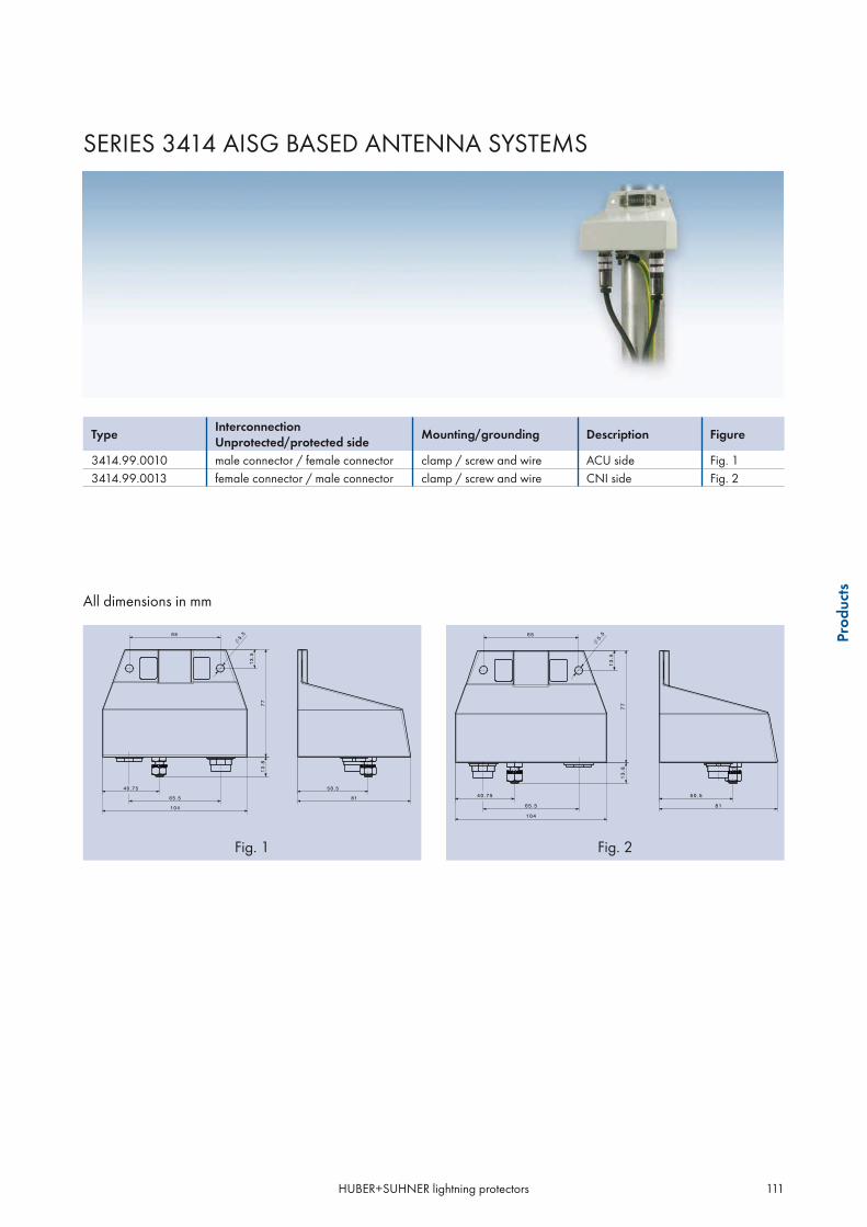
HUBER+SUHNER lightning protectors 111
Prod
ucts
TypeInterconnectionUnprotected/protected side
Mounting/grounding Description Figure
3414.99.0010 male connector / female connector clamp / screw and wire ACU side Fig. 13414.99.0013 female connector / male connector clamp / screw and wire CNI side Fig. 2
Fig. 1 Fig. 2
SERIES 3414 AISG BASED ANTENNA SYSTEMS
All dimensions in mm

HUBER+SUHNER lightning protectors112
The intention of this section is to present products whichare based on protector design constraints but featuringeither special or additional functions.These have been selected from a variety of RFcomponents which make use of the comprehensive
HUBER+SUHNER RF and material know-how.More and more multifunctional products are createdwhich help our customers to solve special system re-quirements of RF applications more neatly and costeffectively.
SPECIALPRODUCTS

HUBER+SUHNER lightning protectors 113
Prod
ucts
SEMPER™ - SELF-EXTINGUISHING GAS CAPSULE PROTECTOR
Description
The patent pending SEMPER concept enhances thesafety and reliability of the well known and proven gascapsule protector principle impressively. It eliminatesthe risk of capsule "hold on" due to DC line power-ing or high powered RF signals, which will renderthe system inoperable and can destroy the protectivecapsule.
HUBER+SUHNER offers two basic concepts of self-ex-tinguishing gas capsule protectors:
mechanical version, named SEMPER™electronic version
The unique and patent pending SEMPER™ solution isrealised as a simple unit which enables the use of thecomprehensive range of HUBER+SUHNER gas cap-sule protectors with a replaceable capsule. An easy
••
retrofit of existing gas capsule protectors is possible oravailable as complete SEMPER™ protectors in a vari-ety of configurations.
The electronic version is realised with the protector se-ries 3405 and is available on request. The main differ-ent characteristic will be found in the faster switchingtime.
Whereas many applications generally benefit fromthe enhanced safety and reliability that the SEMPERconcept offers, applications using DC line power forremote signal amplification and processing and thoseusing high RF power will find self-extinguishing light-ning protectors of specific interest.
Applications
feeding DC over coaxtransmitting high RF powertower mount amplifiers/repeatersGPS receiverspoint to point / multi-point radiosdefence/security radiosremote installationsuninterruptible surveillance radio control or navigation systems
Features and benefits
self-extinguishing gas capsule with automatic recoveryextinguishing under any coaxial line condition including:malfunction of electronic fused DC suppliesmalfunction of RF line monitoringabsence of any such mechanismcan be employed for any HUBER+SUHNER gas capsule protectors with exchangeable gas tubefield replacement allows cost-effective system upgradesproduct options ensure availability for any applicationhigher safetynegligible system downtime
••••••••
••••••••••

HUBER+SUHNER lightning protectors114
Specification
Electrical data
DC current
Turn-off time20 sec. typically at 2.0 A and 25°C ambient temperature< 40 sec. typically below 1 A and 25°C ambient temperature
Recovery time 7 sec. at 25°C ambient temperature
Environmental data Requirements/test conditions
Operation temperature range–40 °C +85 °C (lightning protection functionality)–20 °C +85 °C (SEMPER™ functionality)
Waterproof degree (IEC 60529) IP 65 min., refer to shown product specification, data refer to the coupled state
Temperature shock MIL-STD-202, Meth. 107, Cond. B
Moisture resistance MIL-STD-202, Meth. 106
Vibration MIL-STD-202, Meth. 204, Cond. D
Material data SEMPER™ protector
Piece parts Material Surface plating
Body brass SUCOPLATE®
Female contacts copper beryllium alloy gold or silver plating
Male contacts brass gold or silver plating
Dielectric PTFE
Gasket MVQ (silicone rubber)
Material data SEMPER™ unit
Piece parts Material Surface plating
Body brass SUCOPLATE® or gold
Contact copper beryllium alloy or brass silver plating
Insulator PTFE / AL2O3
Gasket NBR (acrylonitrile butadiene elastomeric)
Insert MVQ (silicone rubber)
Recovery Performance at 25°C
0
5
10
15
20
25
30
35
-40 -20 0 20 40 60 80
Time [s]
Am
bien
t Tem
pera
ture
[°C
]
Turn-off Performance at 25°C
0
5
10
15
20
25
30
35
1.2 1.6 2 2.4 2.8 3.2
Current [A]
Firi
ng T
ime
[s]
Turn
-off
time
(s)
Reco
very
time
(s)
Ambient temperature (°C)Current (A)

HUBER+SUHNER lightning protectors 115
Prod
ucts
Basic working principle
Gas capsule ignited
Switch gap closed
Liquid silicone rubber expanded Switch gap open
Capsule holder
Switch gap closedLiquid silicone rubber
Gas capsule
Normal state before lightning strike and after recovery time
Gas capsule ignited after lightning strike
Activated state, gas capsule extinguished

HUBER+SUHNER lightning protectors116
SEMPER™ PRODUCT RANGE
By offering both, complete SEMPER protector and replaceable SEMPER capsule unit solutions, HUBER+SUHNERare able to provide lightning protection solutions to a wide range of both civil and military applications and sys-tem upgrades.
Type Frequency range (MHz)
Connector configuration Static spark-over voltage
Capsule unit included Figure
3401.17.0048-EX DC – 1000 N-jack/N-jack 230 V 9071.99.0647 Fig. 1
3401.26.0012-EX DC – 1000 TNC-jack/TNC-jack 230 V 9071.99.0647 Fig. 2
3402.17.0072-EX DC – 2500 N-jack/N-jack 230 V 9071.99.0647 Fig. 3
3402.41.0056-EX DC – 2500 7/16-jack/7/16-jack 230 V 9071.99.0647 Fig. 4
3403.17.0056-EX 650 – 2500 N-jack/N-jack 230 V 9071.99.0647 Fig. 5
3409.17.0037-EX 806 – 2500 N-jack/N-jack 90 V 9071.99.0748 Fig. 6
3409.41.0064-EX 806 – 2500 7/16-jack/7/16-jack 90 V 9071.99.0748 Fig. 7
Fig. 1 Fig.2 Fig. 3
SEMPER™ capsule units for retrofit and replacement see page 132.
All dimensions in mm
Fig. 4 Fig.5 Fig. 6
Fig. 7

HUBER+SUHNER lightning protectors 117
Prod
ucts
SERIES 3405, SELF EXTINGUISHING GAS CAPSULE PROTECTOR
- ELECTRONIC VERSION
Description
For some applications the turn-off time of the SEMPER™ concept might be too long or the demand for DC currentis higher. The protector series 3405 which is based on an electronic switching functionality can fill this gap. Themajor differences to the SEMPER™ products are:
short extinguishing timeno recovery timehigh DC current
More information about the series 3405 is availableon request and in the Sales.Net.
Features
extinguishing time of 4 milliseconds typicallyno recovery timeself-extinguishing of the gas capsule under RF andDC conditionsbroad and single band units in the frequency rangewithin 380 MHz and 2.5 GHzlow passive intermodulation product, typically-150 dBchigh RF-CW/average and peak powerfor voltages up to 48 V and power supply shortcircuit currents up to 7 A
•••
•••
•
•
••
Electronic extinguishing protector
Typical switching performance of an electronic extinguishing protector
Legend:1 normal state2 surge occurs and gas capsule ignites3 extinguishing phase4 return to normal state
Ref.
1
2
3
4
120
100
80
-20
0
20
40
60
0 21 3 4- 0.5
ns
THESE PRODUCTS ARE AVAILABLE ON REQUEST.

HUBER+SUHNER lightning protectors118
SERIES 9070 - DC INJECTORS (BIAS-T)
Description
Features Principle
DC injection up to 48 V/2 A Easy insertion into an existing coaxial line
••
HUBER+SUHNER DC injectors have a Bias-T design.They can be easily inserted in a coaxial transceiverline, thus permitting any active electronic equipment tobe powered without additional cabling.These products include a high-pass filter which pro-
vides a DC-blocking on the equipment side meetingthe system requirements of RF applications more neatlyand cost effectively. They play especially an importantrole for reconfigurations of transceivers to enhancecapacity.
RF + DC
antenna side equipment side
RF
DC

HUBER+SUHNER lightning protectors 119
Prod
ucts
Specifications
Electrical data Requirements
RF:
Impedance
Frequency range 300 to 2000 MHz
RL 20 dB min.
IL 0.2 dB max.
RF power transmission 100 W CW max.
DC:
Injection current 2 A max.
DC supply voltage 48 V max.
Mechanical data Requirements
Coupling nut torque force according to IEC/MIL (refer to page 30)
Durability (matings) 500 min.
Environmental data Requirements/test conditions
Operation temperature range – 40 °C...+ 85 °C / – 40 °F...+ 185 °F
Waterproof degree (IEC 60529) refer to product detail specification (data sheet)
Temperature shock MIL-STD-202, Meth. 107, Cond. B
Moisture resistance MIL-STD-202, Meth. 106
Vibration MIL-STD-202, Meth. 204, Cond. D
The product is designed to meet the cited test procedures. Any additional or different requirements arising from specificapplications or environmental conditions not covered by the test specifications mentioned above are subject to request and need to beconfirmed by the single product detail specification.We recommend additional taping for long term outdoor applications in any case.
Material data
Component part Standard Material Plating
Housings QQ-B-626 brass SUCOPLATE®
Male contacts QQ-B-626 brass gold or silver plating
Female contacts QQ-C-530 CuBe2 gold or silver plating
Insulators ASTM-D-1457 PTFE
Gaskets ASTM-E-1418 PS 1 elastomer rubber
THESE PRODUCTS ARE AVAILABLE ON REQUEST.

HUBER+SUHNER lightning protectors120
SERIES 9077 - HIGH VOLTAGE DC BLOCKS
Description
The HUBER+SUHNER DC Block product line includeDC blocks (inner conductor disconnected) and DC-DCblocks (inner and outer conductor disconnected) forgalvanic isolation up to 15 kV. They block high-am-plitude and low-frequency surge voltages e.g. occur-
ring during regular electric railway operation alongrailway lines. They provide sufficient safety even in theworst case scenario if the overhead high voltage linesfall to the ground.
Applications
Generally used along railway tracks and in road and train tunnels enabling safe and uninterrupted communica-tion support for critical services and operation like rescue, police, fire brigades and public radio services suchas broadcasting, mobile telephony and WLAN. Tunnel specific radio systems transmit and receive via radiatingcoaxial cables acting as antennas.
Features
galvanic isolation of the RF signal pathprotects from effects caused by ground potential riseprovides ground potential separationresistant to corrosion caused by parasitic currentDC blocking configuration on centre and/or outer conductorblocking DC voltage up to 15 kVbroadband operation up to 2500 MHzlow intermodulation performancebulkhead mounting and groundingwaterproof designmaintenance free
•••••••••••
2rotcennoc1rotcennoc
centre conductor
outerconductor
2rotcennoc1rotcennoc
centre conductor
outerconductor
DC block DC-DC block
only centre conductor disconnected centre and outer conductor disconnected

HUBER+SUHNER lightning protectors 121
Prod
ucts
4 kV BROADBAND HIGH VOLTAGE DC BLOCK
Specifications
Electrical Data Requirements
RF:
Impedance
Frequency range from 140 MHz to 2500 MHz
RL16 dB min. from 140 MHz to 200 MHz20 dB min. from 200 MHz to 2500 MHz
IL 0.5 dB max.
PIM -150 dBc typ.
RF power transmission 80 W CW
DC:
Leakage current 50 μA
Test leakage current 100 μA
Blocking voltage 4000 V (only centre conductor disconnected)
Mechanical data Requirements
Weight refer to product specification
Mounting hole MH 110, see page 34 - 35
Environmental data Data requirements
Operating temperature range – 40 °C...+ 85 °C
Waterproof degree (IEC 60529) IP 65 min., data refer to the coupled state
Temperature shock MIL-STD-202, Meth. 107, Cond. B
Moisture resistance MIL-STD-202, Meth. 106
Vibration MIL-STD-202, Meth. 204, Cond. D
Material data
Component part Standard Material Plating
Housings QQ-B-626 brass SUCOPLATE®
Male contacts QQ-B-626 brass gold or silver plating
Female contacts QQ-B-530 copper beryllium or bronze gold or silver plating
Insulators ASTM-D-1457 PTFE
Gaskets ASTM-E-1418 PS 1 elastomer rubber

HUBER+SUHNER lightning protectors122
SERIES 9077
Type Connector configuration side 1 Connector configuration side 2 Weight Figure
9077.17.0015 N jack (female) N jack (female) 380 g Fig. 19077.17.0016 N plug (male) N jack (female) 380 g Fig. 29077.41.0015 DIN 7/16 jack (female) DIN 7/16 jack (female) 400 g Fig. 39077.41.0016 DIN 7/16 plug (male) DIN 7/16 jack (female) 400 g Fig. 4
All dimensions in mm
Fig. 1 Fig.2 Fig. 3
Fig. 4

HUBER+SUHNER lightning protectors 123
Prod
ucts
4 kV BROADBAND HIGH VOLTAGE DC-DC BLOCK
Specifications
Electrical Data Requirements
RF:
Impedance
Frequency range from 160 MHz to 2500 MHz
RL22 dB min. from 160 MHz to 300 MHz26.4 dB min. from 300 MHz to 2500 MHz
IL 0.1 dB max.
PIM -150 dBc typ.
RF power transmission 500 W CW
DC:
Leakage current 5 μA
Test leakage current 10 μA
Blocking voltage 4000 V (centre and outer conductor disconnected)
Mechanical data Requirements
Weight refer to product specification
Mounting hole MH 110, see page 34 - 35
Environmental data Data requirements
Operating temperature range – 40 °C...+ 85 °C
Waterproof degree (IEC 60529) IP 65 min., data refer to the coupled state
Temperature shock MIL-STD-202, Meth. 107, Cond. B
Moisture resistance MIL-STD-202, Meth. 106
Vibration MIL-STD-202, Meth. 204, Cond. D
Material data
Component part Standard Material Plating
Housings QQ-B-626 brass SUCOPLATE®
Male contacts QQ-B-626 brass gold or silver plating
Female contacts QQ-B-530 copper beryllium or bronze gold or silver plating
Insulators ASTM-D-1457 PTFE
Gaskets ASTM-E-1418 PS 1 elastomer rubber

HUBER+SUHNER lightning protectors124
SERIES 9077
Type Connector configuration side 1 Connector configuration side 2 Weight Figure
9077.17.0031 N jack (female) N jack (female) 456 g Fig. 19077.17.0030 N plug (male) N jack (female) 459 g Fig. 29077.41.0031 DIN 7/16 jack (female) DIN 7/16 jack (female) 459 g Fig. 39077.41.0032 DIN 7/16 plug (male) DIN 7/16 jack (female) 466 g Fig. 4
All dimensions in mm
Fig. 1 Fig.2 Fig. 3
Fig. 4

HUBER+SUHNER lightning protectors 125
Prod
ucts
15 kV BROADBAND HIGH VOLTAGE DC-DC BLOCK
Specifications
Electrical Data Requirements
RF:
Impedance
Frequency range from 180 MHz to 2500 MHz
RL16 dB min. from 180 MHz to 380 MHz20 dB min. from 380 MHz to 2500 MHz
IL 0.5 dB max.
PIM -150 dBc typ.
RF power transmission 80 W CW
DC:
Leakage current 50 μA
Test leakage current 100 μA
Blocking voltage 15000 V (centre and outer conductor disconnected)
Mechanical data Requirements
Weight refer to product specification
Mounting hole MH 110, see page 34 - 35
Environmental data Data requirements
Operating temperature range – 40 °C...+ 85 °C
Waterproof degree (IEC 60529) IP 65 min., data refer to the coupled state
Temperature shock MIL-STD-202, Meth. 107, Cond. B
Moisture resistance MIL-STD-202, Meth. 106
Vibration MIL-STD-202, Meth. 204, Cond. D
Material data
Component part Standard Material Plating
Housings QQ-B-626 brass SUCOPLATE®
Male contacts QQ-B-626 brass gold or silver plating
Female contacts QQ-B-530 copper beryllium or bronze gold or silver plating
Insulators ASTM-D-1457 PTFE
Gaskets ASTM-E-1418 PS 1 elastomer rubber

HUBER+SUHNER lightning protectors126
SERIES 9077
Type Connector configuration side 1 Connector configuration side 2 Weight Figure
9077.17.0022 N jack (female) N jack (female) 657 g Fig. 19077.17.0006 N plug (male) N jack (female) 660 g Fig. 29077.41.0009 DIN 7/16 jack (female) DIN 7/16 jack (female) 660 g Fig. 39077.41.0010 DIN 7/16 plug (male) DIN 7/16 jack (female) 667 g Fig. 4
All dimensions in mm
Fig. 1 Fig.2 Fig. 3
Fig. 4

HUBER+SUHNER lightning protectors 127
Prod
ucts
SPACE FOR YOUR NOTES

HUBER+SUHNER lightning protectors128
Protect
your valuable electronic equipment
The "SUHNER" the better!

HUBER+SUHNER lightning protectors 129
Acc
esso
ries
PRODUCT ACCESSORIES
Page
Gas capsules 130
Gas capsules 131Definitions 133Selection of a suitable gas capsule 133
Accessories 134
Protective caps 134Mounting sets - washers, V-washers, nut 135Blanking plugs 136Grounding rings 137Mounting screw sets 137Mounting brackets 138Grounding kits for coaxial cables 139

HUBER+SUHNER lightning protectors130
GAS CAPSULES
HUBER+SUHNER gas capsule protectors are normally delivered without capsule. This allows the customer toselect the appropriate capsule according to his application conditions, especially the maximum operation signalamplitude.Exceptions: All protectors of the following series are supplied with properly installed gas capsule.
Protectors with replaceable gas capsule• series 3403 - Fine protectors• series 3409 - high-power/low-IM protectors• series 3410 - high-power/low-IM protectors with integrated high-pass filter and DC injection
Protectors with fix installed gas capsule (no replacement possible)• series 3404 - miniature gas capsule protectors• series 3406 - Slim Line gas capsule protectors• series 3412 - hybrid and Fine coaxial data line protectors
Specification Requirements
Insulation resistance 100 V (50 V for 9071.99.0X48) 1010
Glow voltage 10 mA 70 V
Arc voltage >1 A 10 V
Glow-arc transition current < 0.5 A
Capacitance 1 MHz <1 pF typ.
Impulse discharge current
30 kA, 8/20 μs20 kA, 8/20 μs8 kA, 10/350 μs500 A, 10/1000 μs100 A, 10/1000 or 10/700 μs
1 operation minimum>10 operations1 operation minimum>400 operations>1000 operations
Alternating discharge current65 Arms, 11 cycles10 Arms, 1 s
1 operation minimum> 10 operations
Operating temperature-40 to +85°C-55 to +125°C capsule only
Notes:UL recognized components, UL file E153537Designed for operations exceeding 25 years
••

HUBER+SUHNER lightning protectors 131
Acc
esso
ries
Type UZstat UZdyn max. IS 8/20 μs ISG 8/20 μs UARC Dim. Figure(V) (V) (kA) (kA) (V) (mm)
9071.99.0547 230 ±15 % 675 20 30 10 – 15 6x8 Fig. 19071.99.0548 90 ±20 % 500 20 30 10 – 15 6x8 "9071.99.0549 350 ±15 % 875 20 30 10 – 15 6x8 "9071.99.0550 470 ±15 % 1000 20 30 10 – 15 6x8 "9071.99.0551 600 ±15 % 1100 20 30 10 – 15 6x8 "
All dimensions in mm
Gas capsules
Fig. 1
Suitable for the following installed capsule holders:
Type UZstat UZdyn max. IS 8/20 μs ISG 8/20 μs UARC Dim. Figure(V) (V) (kA) (kA) (V) (mm)
9071.99.0447 230 ± 15 % 675 20 30 10 – 20 * Fig. 29071.99.0448 90 ± 20 % 500 20 30 10 – 20 * "9071.99.0449 350 ± 15 % 875 20 30 10 – 20 * "9071.99.0450 470 ± 15 % 1000 20 30 10 – 20 * "9071.99.0451 600 ± 15 % 1100 20 30 10 – 20 * "
* 6x8 mm gas capsules of the first table together with capsule holder with groove
All dimensions in mm Suitable for the following installed capsule holders:
Gas capsule together with capsule holder
Fig. 2

HUBER+SUHNER lightning protectors132
SEMPER™ gas capsule units for retrofit and replacement for series 3401, 3402 and 3403
Type UZstat UZdyn max. IS 8/20 μs ISG 8/20 μs UARC Figure(V) (V) (kA) (kA) (V)
9071.99.0647 230 ± 15 % 675 20 30 10 – 20 Fig. 19071.99.0648 90 ± 20 % 500 20 30 10 – 20 "9071.99.0649 350 ± 15 % 875 20 30 10 – 20 "9071.99.0650 470 ± 15 % 1000 20 30 10 – 20 "9071.99.0651 600 ± 15 % 1100 20 30 10 – 20 "
All dimensions in mm
SEMPER™ gas capsule units for retrofit and replacement for series 3409
Type UZstat UZdyn max. IS 8/20 μs ISG 8/20 μs UARC Figure(V) (V) (kA) (kA) (V)
9071.99.0747 230 ± 15 % 675 20 30 10 – 20 Fig. 29071.99.0748 90 ± 20 % 500 20 30 10 – 20
All dimensions in mm
Fig. 1
Fig. 2

HUBER+SUHNER lightning protectors 133
Acc
esso
ries
Definitions
UZstat
Static spark-over voltage – voltage which ignites the capsule in the case of a voltage rise of less than 100 V/ms.
UZdyn
Dynamic spark-over voltage – max. voltage which ignites the capsule in the case of a voltage rise of 1 kV/μs.
IS
Impulse discharge current – peak value of a defined current pulse which is allowed to be applied at least ten times at intervalsof 30 seconds without causing any significant changes of the spark-over voltage specification. Values are given for currentpulse shape definitions of 8/20 μs (rise time/half-value period).
ISG
Maximum pulse current – peak value of a defined single current pulse which can be conducted to ground once. For pulse shape referto IS.
UB
Glow discharge voltage – residual voltage across the capsule when the discharge current operates the capsule in the glowstate, typically at 10 mA.
UARC
Arc voltage – increasing current drives the capsule into the arc state. The resulting voltage across the capsule is the arc voltage.
Selection of a suitable gas capsule
According to RF power transmission
A calculation method for VSWR = 1 is explained in section 4, «How to Select the Right Product», page 145.For maintenance requirements please refer to page 152.
1500 V
static spark-overvoltage
350 V470 V600 V900 V
1200 V
90V
230 V
static spark-overvoltage
1500 V
350 V470 V600 V900 V
1200 V
90V
230 V

HUBER+SUHNER lightning protectors134
ACCESSORIES
Protective Caps
Type Suitable for connector interface
Dimensions (mm/in)
A B C L
62_BNC-0-0-15* BNC neg. 17.0/0.67 14.5/0.57 4.0/0.16
62_TNC-0-0-1* TNC neg. 17.0/0.67 16.0/0.63 4.0/0.16
62_N-0-0-9* N neg. 21.0/0.83 20.5/0.81 4.0/0.16
62_7/16-0-0-1*/** 7/16 neg. 34.0/1.34 32.1/1.26 4.3/0.17
* waterproof in connected condition
** black plastic-coated steel cable

HUBER+SUHNER lightning protectors 135
Acc
esso
ries
Mounting sets – washer, V-washer, nut (and O-Ring)
Standard sets (without O-ring according to protectordesign and original delivery)
Type Suitable for protectors with mounting hole(MH dimensions refer to page 34 – 35)
9075.99.0035 MH12, MH50, MH119 (nut thickness 3.30 mm / 1/8")
9075.99.0036 MH12, MH50, MH119 (nut thickness 4.75 mm / 3/16")
9075.99.0043 MH25
9075.99.0074 MH72
9075.99.0086 MH80
9075.99.0085 MH69
Special sets (with additional O-ring according toprotector design and original delivery)
Type Suitable for protectors with mounting hole(MH dimensions refer to page 34 – 35)
9075.99.0039 MH118
9075.99.0040 MH74
9075.99.0041 MH12, MH50 (nut thickness 3.30 mm / 1/8")
9075.99.0042 MH12, MH50 (nut thickness 4.75 mm / 3/16")

HUBER+SUHNER lightning protectors136
Blanking plugs
Blanking plugs can be used to seal bulkheads or panels, where optional lightning protectors are not yet installed.
The included soft-copper washer provides both water/dust protection and excellent RF shielding.
Type Suitable for mounting hole(MH dimensions refer to page 34–35
Thread length
9075.99.0056 MH12, MH50 11.5 mm/0.453 in
9075.99.0058 MH72 23.6 mm/0.929 in
9075.99.0061 MH74 23.6 mm/0.929 in
9075.99.0064 MH12, MH50 22.4 mm/0.882 in
Grounding cables
Customized grounding cables made from grounding wire AWG 6 and fitted with cable terminals are available onrequest.

HUBER+SUHNER lightning protectors 137
Acc
esso
ries
Grounding rings – cable terminals for HUBER+SUHNER lightning protectors with N and TNC interface
To be applied directly on the bulkhead fixation thread of the protector, if it is not possible to provide a properbonding/grounding via bulkhead.Installation outside of the protected area recommended.
HUBER+SUHNER Type Suitable for mounting hole or screw diameter
9075.99.0026* < 17 mm/ 0.669 in
9075.99.0027* 17...20 mm/ 0.669 ... 0.787 in
9075.99.0031* screw 6 mm/ 0.236 in (1/4“)
9075.99.0032* screw 8 mm/ 0.315 in
* recommended grounding wire size AWG 6 (16 mm2)
Mounting screw sets
For screw mounting of protectorsConsisting of screw, tooth washer and nut
HUBER+SUHNER Type Thread size Screw length Wall thickness max.
9075.99.0096 M6 20 mm/0.79 in 4 mm/0.16 in
9075.99.0012 M8 20 mm/0.79 in 4 mm/0.16 in
9075.99.0023 M8 30 mm/1.18 in 14 mm/0.55 in
9075.99.0017 M8 40 mm/1.57 in 24 mm/0.94 in

HUBER+SUHNER lightning protectors138
Type Suitable for protectors with mounting hole– face 1– face 2
Figure
9075.99.0028MH 69MH 12, 24, 50, 71, 119
Fig. 1
9075.99.0030MH 80, 118MH 25, 70
Fig. 2
9075.99.0095 MH110 Fig. 3
Mounting brackets
Brackets for bulkhead mounting of protectors
Right angle design made from # 8 gauge (3.3 to4.2 mm) copper sheetEach face features 4 wall mounting holes of size6.7 mm/0.265 in diameterDimensions:– large hole face: 76x76 mm (3.00x3.00 in)– small hole face: 50x76 mm (2.00x3.00 in)
•
•
•
Fig. 1 Fig. 2 Fig. 3

HUBER+SUHNER lightning protectors 139
Acc
esso
ries
SERIES 9076
Grounding kits for coaxial cables
HUBER+SUHNER series 9076 grounding kits enable reliable grounding of today’s usual corrugated copper tubeand RG cables for radio transmitter antenna installations.
Features
quick and easy installationno loose piece parts
grounding cable AWG6 (16 mm2)current handling capability 100 kA 8/20 μs,25 kA 10/350 μswaterproof IP67corrosion resistant
Materials
Metal mounting parts: stainless steelContact part: copperGasket: EPDM
Products
1. Straight (right angle to corrugated copper tubecable) grounding cable connection
Type “N” For cable sizeSucofeed,Andrew,Nokia,Kabelmetal,RFS,Eupen,etc.
“A”(mm)
“B”(mm)
“C”(mm)
Stripping length
Grounding screws
Weight (g)
Cable dia-meter (mm)
9076.99.N014 1/4”, RG213/214* 840 50 28 26 M8 250 10 – 119076.99.N038 3/8” 840 50 28 26 M8 250 12 – 139076.99.N013 1/2” highflex 840 50 32 26 M8 260 13 – 149076.99.N012 1/2” 840 50 32 26 M8 260 16 – 179076.99.N078 7/8” / 7/8" highflex 840 50 44 26 M8 290 26 – 289076.99.N114 1 - 1/4” 840 70 59 26 M8 500 38 – 409076.99.N158 1 - 5/8” 840 70 69 30 M8 530 50 – 52
* including 3/8" highflex
•••••
••

HUBER+SUHNER lightning protectors140
2. Parallel (aligned to corrugated copper tube cable)grounding cable connection
Type “P” For cable sizeSucofeed,Andrew,Nokia,Kabelmetal,RFS,Eupen,etc.
"A"(mm)
“B”(mm)
“C”(mm)
Stripping length (mm)
Grounding screws
Weight (g)
Cable dia-meter (mm)
9076.99.P014 1/4”, RG213/214* 840 50 28 26 M8 250 10 – 119076.99.P038 3/8” 840 50 28 26 M8 250 12 – 139076.99.P013 1/2” highflex 840 50 32 26 M8 260 13 – 149076.99.P012 1/2” 840 50 32 26 M8 260 16 – 179076.99.P078 7/8” / 7/8” highflex 840 50 44 26 M8 290 26 – 289076.99.P114 1 - 1/4” 840 70 59 26 M8 500 38 – 409076.99.P158 1 - 5/8” 840 70 69 30 M8 530 50 – 52
* including 3/8" highflex
Stripping Dimensions
Concerning the necessary cable jacket length whichhas to be removed, refer the tables above, column«stripping length». Select according to type number.
The mounting instruction is shipped with every kit.It can also be obtained as download from our homepage (LP accessories) or the catalogue CD-ROM.
stripping length
HUBER+SUHNER lightning protectors 141
Acc
esso
ries
SPACE FOR YOUR NOTES

HUBER+SUHNER lightning protectors142
Your worldwide partner
flexible, reliable, excellent product quality

HUBER+SUHNER lightning protectors 143
App
licat
ion
note
s
APPLICATION NOTES
Page
How to select the right product 144Selection according to surge current handling capability 144Selection of the surge protection gas capsule 145
Basic installation and grounding rules 146
General protection recommendations 146Mounting and grounding recommendations 150
Maintenance requirements 152Quarter-wave lightning protectors 152Gas capsule lightning protectors 152
IP dust and water protection rating 153
Passive intermodulation issues 154
Electrochemical potential differences - outdoor applications 156
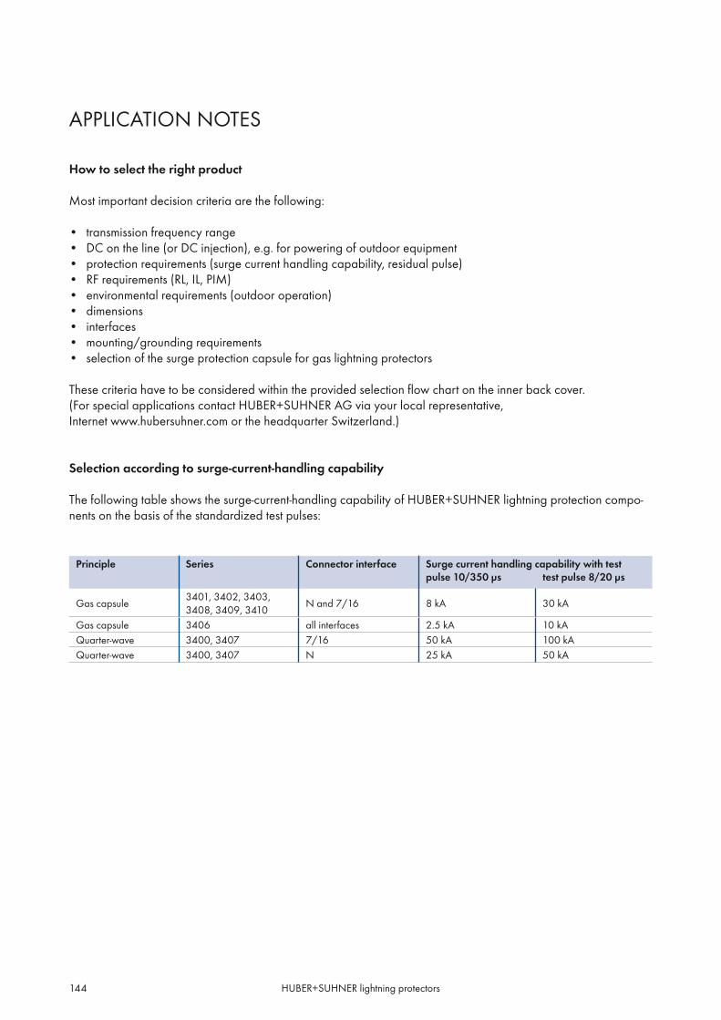
HUBER+SUHNER lightning protectors144
APPLICATION NOTES
How to select the right product
Most important decision criteria are the following:
transmission frequency rangeDC on the line (or DC injection), e.g. for powering of outdoor equipmentprotection requirements (surge current handling capability, residual pulse)RF requirements (RL, IL, PIM)environmental requirements (outdoor operation)dimensionsinterfacesmounting/grounding requirementsselection of the surge protection capsule for gas lightning protectors
These criteria have to be considered within the provided selection flow chart on the inner back cover.(For special applications contact HUBER+SUHNER AG via your local representative,Internet www.hubersuhner.com or the headquarter Switzerland.)
Selection according to surge-current-handling capability
The following table shows the surge-current-handling capability of HUBER+SUHNER lightning protection compo-nents on the basis of the standardized test pulses:
Principle Series Connector interface Surge current handling capability with test pulse 10/350 μs test pulse 8/20 μs
Gas capsule3401, 3402, 3403,3408, 3409, 3410
N and 7/16 8 kA 30 kA
Gas capsule 3406 all interfaces 2.5 kA 10 kA Quarter-wave 3400, 3407 7/16 50 kA 100 kA Quarter-wave 3400, 3407 N 25 kA 50 kA
•••••••••

HUBER+SUHNER lightning protectors 145
App
licat
ion
note
s
Selection of the surge protection gas capsule
RF power
A total of eight capsules with different static spark-over voltages are available. To select the correct capsule, thefollowing criteria must be known:
max. RF transmission power P (CW or PEP)supply voltage (U) if usedsystem impedance Zmax. allowable VSWR (system adjustment)
The required static spark-over voltage (refer to tables on pages 131 and 132, consider the lowest pos-sible voltage from the tolerance range!) is 1.5 times of the total peak voltage on the transmission line. The following formula is applicable for the peak voltage, if VSWR=1.
Û = 2 PZ (1 + ) + U
For multicarrier systems, the (inphase) peak voltage must be calculated as the total of all single peak voltages:
Û = (Û1 + Û2 +... Ûn) = 2 P1Z + 2 P2Z +... + 2 PnZ (1 + ) + U
This consideration does not involve effects of the modulation. They have to be added according to the selectedmodulation principle.
The admissible RF power (CW or PEP) versus the VSWR is shown in the following diagram for HUBER+SUHNERsurge protection capsules.
••••
1500 V
static spark-overvoltage
350 V470 V600 V900 V
1200 V
90V
230 V
static spark-overvoltage
1500 V
350 V470 V600 V900 V
1200 V
90V
230 V
(1 + ) + U ( )

HUBER+SUHNER lightning protectors146
Current distribution without application of lightning protection components
LPZ: Lightning protection zonePL: Protection level (according to IEC 61024-1/IEC 61312-1)
45° (PL lll)
i 50%
LPZ 0A
Data and power supply lines(remote earth)
Bonding bar
i 16%LPZ1
BTS
i 50%
i 70%
LPZ 0B
i 14%
Grounding of coaxial cable screen(outer conductor)
Direct and indirect lightning strokes are mainly accom-panied by resistive and magnetic coupling processesof their electrical energy. Capacitve coupling effects ofsurge energy by the high and fast-changing electricalfield just before the lightning stroke occurs are negli-gible, if the system is well bonded to earth (electricalcharge equalization).
The following figure shows the lightning current distri-bution after a stroke into the antenna mast, respectivelyinto the lightning protection system, caused by resistivecoupling (equal current distribution as proven assump-tion according to IEC 61312-1, Protection against light-ning electromagnetic impulse):
BASIC INSTALLATION AND GROUNDING RULES
General protection recommendations
Model base station antenna system

HUBER+SUHNER lightning protectors 147
App
licat
ion
note
s
Recommendations
The following illustrates the resistive current distribution with lightning protection components (e.g. quarter-waveprotectors) in detail:
45° (PL lll)
i 50%
LPZ 0A
Data and power supply lines(remote earth)
Bonding bar
LPZ1
i 50%
i 70%
LPZ 0B
i 30%
Grounding of coaxial cable screen(outer conductor)
Lightning protectors
LPZ2BTS
Antennas should be located within the protection zone of the external lightning protection system (according to IEC 61024-1, Protection of structures against lightning: air-terminations, down-conduc-tors and earth-termination) – LPZ 0B. It is estab-lished as a 45° area downwards, related to the high-est point of the air-termination as shown (assumptionfor a mast height up to 20 m and the protection levelIII according to IEC 61024-1).LPZ 0B can principally be evaluated by the applica-tion of the sphere model according to IEC 61024-1,which allows to determine LPZ 0B for even more com-plicated structures.
Thus, the antenna is protected against direct lightningstrokes with a probability of 90% (PL III according toIEC 61312-1). But the electromagnetic field still actsunattenuated!
By the bonding of the antenna earth/upper-cable
end screen to the down-conductor of the mast or the building. Surge voltages caused by magneticcoupling of direct and near lightning strokes into loopsthrough earth can be avoided. If not done, the cableswould have to be protected magnetically by iron tubes (which would also protect the inner conductor of co-axial cables).
Low-frequency short-circuit connection of an-tennas against down-conductor (e.g. shunt-fed antennas or application of quarter-wave protec-tors). This helps avoiding a high surge voltage andtherefore a possible undefined breakdown in the cabledue to magnetic coupling of direct and near lightningstrokes into loops across earth or remote earth). Di-rect-stroke-initiated partial lightning currents over thecoaxial cable screen would otherwise cause togetherwith the measure of the previous section undefined ca-ble breakdown by the voltage drop against earth (asthe inner conductor can have zero potential).

HUBER+SUHNER lightning protectors148
Surge pulse
generator
Inner conductor
Outer conductor/screen
OscilloscopeY-port
Coaxial cable
UL
Bonding of the cable screen to the down-con-ductor where it leaves the mast and with higher masts every 20 m. Thus, a potential equalizationis achieved and the current over the cable screen toearth is reduced, as the down conductor has a lowerimpedance.
Application of coaxial cables with low DC resis-tance over inner and outer conductor (e.g. cor-rugated copper tube cables of as large size as possible – larger size means also higher dielectric withstanding voltage).
Application of reliable lightning protection com-ponents at the entry of LPZ 1. Thus, high partiallightning and induced currents (simulating test pulse10/350 μs according to IEC 61312-1) can be led toearth and over-voltages are reduced to a low level(potential equalization). HUBER+SUHNER ran severaltests to evidence the necessity of this measure. The ca-bles RG 213, LMR 400, LDF 4-50A (1/2“) andLDF 5-50A (7/8“) were measured in the case of a re-sistive/inductive equipment input:
Measurement of the longitudinal voltage over the inner conductor
Here a test surge current of pulse shape 8/20 μs(and 10/350 μs) was sent into a 1 m piece ofcable, inner and outer conductor connected at theinput, output screen connected to earth and innerconductor to the oscilloscope input.Most important result: applying the 8/20 μs testpulse with 25 kA amplitude (half of the assumedload of the model antenna system, as 100 kA is thetotal lightning current according to PL III) leads to alongitudinal voltage of:
•
•
RG 213: 867 V LMR 400: 1438 V LDF 4-50A: 356 V LDF 5-50A: 133 V
(if a cable lengths of 10 m is assumed,for example).
The longitudinal voltage is proportional to cable lengthand partial lightning current amplitude!
Measurements with lightning currents of pulse shape10/350 μs resulted as expected in longitudinal volt-ages of smaller amplitude (due to the lower rise time)but much higher pulse energy.
In case of DC injection over the coaxial cable to supply power for active electronic circuits in the antenna system, only gas capsule lightning pro-tectors can be employed. The residual pulse voltagebehind the protector reaches up to several hundredvolts over some nanoseconds, dependent on the se-lected gas capsule.
This requires additional protection components for sen-sitive input circuits of electronic devices. They can belocated directly behind the gas capsule lightning pro-tector (or be a combined arrangement), if the deviceto be protected is nearby. Normally they should beplaced at the entry of next protection zone, if a conse-quent zone concept is being followed (e.g.LPZ 2 – according to IEC 61312-1 every zone transi-tion requires a separate lightning/surge protectioncomponent). The additional protector – here calledsurge suppressor due to its function – reduces thesurge pulse voltage to a well-tolerated extent of only afew volts (e.g. HUBER+SUHNER Fine Protectors).

HUBER+SUHNER lightning protectors 149
App
licat
ion
note
s
Induction circuit
Bonding barRF/Data
Power supply
Earth termination system
Such a surge suppressor is not only required due to theleftover residual pulse of the gas capsule lightning pro-tector, but also due to magnetic coupling into the pos-sible loop which the antenna cable length between thelightning protector and the equipment is part of (withinzone LPZ 1). This is illustrated by the following:
Thirty meters of coaxial cable can form together withother signal, energy or bonding connections largeinduction circuits, which produce induced voltages ofseveral hundred kV. Already the coaxial cable alonecan act as an induction circuit for the strong mag-netic fields of near lightning strokes, if not speciallyscreened.
The induced voltage can be calculated with the follow-ing formula:
U = – M2 di/dt (M2 – mutual inductance of the loop,i – lightning current).First partial lightning strokes show a current rate ofchange of up to 20 kA/μs, subsequent lightningstrokes even of up to 200 kA/μs. The loop inductiv-ity depends on the loop circumference and on thedistance to the lightning stroke channel. Larger loops– e.g. 40 m – possess a M2 of about 1.5 mH at adistance of 10 m; with 1 m it increases to about 5 mH.Therefore, induced voltages ranging from 24 to1000 kV can be produced.
Measures to minimize or compensate in-house lightning induction effects:
application of surge protectors and suppressorsshort cable lengthsmagnetic screening of cables (steel tubes/cabletunnels)magnetic screening of the complete structure (Fara-day shield)distance to the possible lightning current channel aslarge as possiblehybrid earth-grounding system – single-pointgrounding, suitable line routing
Active electronic circuits in the antenna and addi-tional line amplifiers have to be protected against surge pulses supplied from the connected coaxial cables (application of lightning protectors and surge suppressors, high-pass not allowed with DC injection) and if possible also against magnetic coupling.Concerning the otherwise occurring surge load referto section application of reliable lightning protectioncomponents.
For a complete lightning/surge protection of a base station, you must consider all further connected signal and power supply lines. Theyhave to be protected under similar considerations.HUBER+SUHNER can recommend certain reliablelightning protection solutions for these purposes.
•••
•
•
•

HUBER+SUHNER lightning protectors150
Mounting and grounding recommendations
The HUBER+SUHNER lightning protector productrange offers a high flexibility to meet mounting andgrounding requirements in the field.Basically all mounting options are simultaneously suit-able for grounding purposes.HUBER+SUHNER offers:
Bulkhead mounting
Preferred mounting/grounding!
– protection zone principle– lowest contact resistance– corrosion-resistant contact zone– waterproof wall sealing– RF leak-proofness– vibration resistance
screw mounting and bracket mounting
For best protection according to IEC 61312-1 whenestablishing protection zones consequently, it is recom-mended to deploy bulkhead mounting facilities. Thusthe protectors can be installed as wall feed-throughdirectly in the wall of the protected room. Doing so,the protectors should be installed consequently withthe surge down conducting part – stub or gas capsule– outside of the protected area not to cause any un-
•
••
necessary interferences when dissipating surges. (Thisis reflected by the recommendations and definitions for«unprotected and protected side» of the componenttables. Bulkhead mounting types and all high-pass filtertypes are marked accordingly.)
The special HUBER+SUHNER bulkhead fixation de-sign automatically enables a good long-term perform-ance concerning a waterproof bulkhead transition, acorrosion-resistant (gas-tight) contact area resulting ina stable contact to the bulkhead ground-plane, a lowtransition resistance and a vibration-resistant mountingof the protector (assuming the right sufficient torqueforces are applied as shown in the supplied assemblyinstructions).
This is true for standard sheet metal bulkheads suchas stainless steel, copper or chrome-plated aluminiumwith standard surface roughness and mounting holesaccording to the related HUBER + SUHNER productmounting hole specification.
For other mounting solutions care has to be taken forminimum interference. But generally all mounting op-tions can carry the specified surge current when prop-erly installed.
Grounding/bonding rules!
For a good grounding respectively bonding the follow-ing has to be considered:
During installation, the lightning protection compo-nents must be connected with the central groundingpoint of the equipment (central grounding bar) ina low-resistance and low-inductance way. Inade-quate grounding concepts with ground loops, insuf-ficiently sized grounding cables (smaller than16 mm2/AWG 6), poor connections, etc., willincrease the residual energy behind the lightningprotector as a result of high impedance (ohmic re-sistance by length and size and in addition induct-ance by length).The contact points of the ground connection mustoffer good electrical conductivity (contact pointsmust be bare and free from dirt, dust and moisture).
•
•

HUBER+SUHNER lightning protectors 151
App
licat
ion
note
s
When threaded contacts are tightened (bulk-head grounding, capsule holder), the minimumtorque specified by the manufacturer must beobserved in order to minimize the contact re-sistance and to establish the effects mentionedabove.The lightning protection components shouldwherever possible be located in the unprotect-ed zone in order to rule out inductive interfer-ence.HUBER+SUHNER lightning protection compo-nents are characterized by their quick, easy, and atthe same time reliable installation methods.The preferred variant is single-hole mountingas wall feed-through. They can be applied withround or with D- or H-shaped mounting holesto prevent rotation. The mounting hole size ismatched to the connector size and thereby tothe forces acting on the component.
•
•
•
All this is crucial for achieving the lowest possible residual surge pulse (voltage and energy) on the protected side and with it keeping the interference load for the equipment as low as possible.
All HUBER+SUHNER lightning protection com-ponents are supplied along with an installationinstruction describing the proper installation proc-edure.

HUBER+SUHNER lightning protectors152
MAINTENANCE REQUIREMENTS
Quarter-wave lightning protectors
Quarter-wave lightning protectors are basically main-tenance-free. However, we recommend customers tocheck the condition of the grounding/bonding systemconnections and of the connector interfaces in thecontext of routine system maintenance. But connectorinterfaces which are heavily damaged by lightningcurrent overload (in excess of specification) will leadto increased reflections and will be detected by the re-turn loss tracing circuit of the transmitter anyway. Fieldexperience shows that lightning protectors are not theonly components which can be affected in such casesof direct hits.
Gas capsule lightning protectors
Gas capsule protectors use different technology, butare still very reliable products. The MTBF value deter-mined by the carefully selectedHUBER+SUHNER gas capsule is about 10 fit (1 fit isdefined as 10-9 h-1) – one failure within 108 hours. Thisis true, as long as no events of critical surge currentload occur.
A degradation of the gas capsule is possible due tosurge current overload and multiple loads at the speci-fication limit. But a lot of tests previously conductedreveal that there is a large safety margin built in toHUBER+SUHNER gas capsules. Even with excessiveoverload the capsules maintain at least their dynamicswitching performance (dynamic spark-over voltagespecification) which determines the residual pulse am-plitude left by transient surges of lightning events.
Any destruction of the capsule due to a heavy over-load would lead to a short, due to its unique andspecial design, and therefore shutdown the transmit-ter. This will be recognised immediately. But this ismost probably not the only system damage in suchcases and a service will be necessary anyway.HUBER+SUHNER protectors feature an easy access tothe capsule and the exchange is quickly made.
Generally, inspection and maintenance schedules de-pend on the grade and frequency of surge loads. Thisis determined by the isokeraunic level (number of thun-
derstorm days, which decreases with latitude) of theoperation area and several factors which determinethe exposure of the equipment (e.g. altitude, countryprofile, nearby structures, water, etc., and even the ex-istence of a lightning protection system). This is the rea-son that only the operator or his local consultant canjudge the inspection requirements of their equipment(e.g. BTS), according to the actual exposure.
Recommendation!
We recommend as a general rule to test the staticspark-over voltage of the capsules in the course of aroutine inspection every 5 years and to exchange thefailing parts. A suitable test unit can be supplied byHUBER+SUHNER (type 9075.99.0053).
As an alternative, a general overall replacement with-out testing might be more cost-effective in certain situ-ations.
After a direct hit which caused damages in the anten-na system, the capsules of the gas capsule protectorsinvolved should be exchanged during the service inany case.

HUBER+SUHNER lightning protectors 153
App
licat
ion
note
s
This section is intended to provide a short overviewand essentials of the classification only. For more de-tails refer to the latest original publication IEC 60529(direct ordering or list of local sources via Internetwww.iec.ch).
IP rating (IP XY)
First number XProtection against ingress of solid objects
no protection
protection against objectslarger than 50 mm diameter
protection against objectslarger than 12.5 mm diameter
protection against objectslarger than 2.5 mm diameter
protection against objectslarger than 1.0 mm diameter
no protection
vertically dripping water
dripping water, 15° tilted
spraying water
splash water
water jets
powerful water jets
continuous immersion(test to be agreed, but exceeding no. 7)
protection against dust(limited ingress, not harmful)
protection against dust(dust-tight, no ingress)
1
2
6
7
0
5
4
3
6
1
2
0
4
3
5
Second number YProtection against ingress of water
temporary immersion(test 1 m, 30 min.)
8
IP DUST AND WATER PROTECTION RATING

HUBER+SUHNER lightning protectors154
All PIM-specified HUBER+SUHNER lightning protec-tors and their piece parts are designed according tothe latest knowledge of PIM theory and practice. Thisis a continuous, progressive process.
Generation of Passive Intermodulation Products (PIM)
Non-linear behaviour of elements in signal pathused with more than one carrier generates IM.
The occurring spectral lines of the IMP can be de-scribed as:
fIMx = mf1 + mf2 + ... + y fm
where f...fm are the used carrier frequencies m...y are pos. or neg. integers fIMx =frequency of one generated IMP
IM spectrum by use of two carrier frequencies
Absolute linearity exists only as a mathematicalidealization – passive elements are all weakly non-linear.
Problem with PIM only occurs by: – high transmit levels – high receiver sensitivity – several transmit channels and – where only one antenna for transmission and receive path is used.
Once in receive band, PIM cannot be reduced byfiltering.
In passive elements there are some dominant con-tributors of non-linearity:
•
•
•
•
•
•
– similar or dissimilar metal-to-metal joints – plasma effects (local high fields causing – corona) – magnetic non-linear effects – high-current density
For cable and connectors the metal-to-metal jointsare the most significant PIM contributors.
Gold, silver, copper, brass and copper-berylliumjoints generate low PIM; steel, aluminium, stainless-steel-joints generate higher PIM.
In practice:
The IM level generated over the whole signal pathis a result of many IM sources. The value of theresulting IM level depends on the phase relation ofall these sources (constructive or destructive interfer-ence). This phase relation varies with frequency.
IMP of two sources
Resulting product
Relation between frequency and IM level
•
•
•
PASSIVE INTERMODULATION ISSUES

HUBER+SUHNER lightning protectors 155
App
licat
ion
note
s
HUBER+SUHNER measurement setup
IMP’s of different order have different frequencies,and hence the resulting product does not have aconstant amplitude.
PIM’s of different measurement setups are not ex-actly comparable (because of the different phaserelations).
The 3rd order IMP’s have the higher value and nor-mally are used to describe the IM behaviour of thedevice under test (DUT).
In theory the IM level increases 3 dB per 1 dBpower increase of the carriers. So, it is importantwhen comparing different measured IM levels toconsider the input power level. A standard valuefor input power is 2 x 20 W (46 dBm).
•
•
•
•
All elements in the measurement setup generateIM. This ground level limits the measurement range(–120 dBm –120 dBm – 46 dBm= –167 dBc).
It is not possible to measure a single connector.Only assemblies can be measured.
The measured level can vary up to 40 dB byvibration or bending of the cable. So we have toknow if the application of the assembly is mechani-cally static or dynamic.
It is difficult to give a typical value for a connector.It depends on the method of mounting (removecable isolation, crimping, clamping, soldering andcontamination).
•
•
•
•
46

HUBER+SUHNER lightning protectors156
ELECTROCHEMICAL POTENTIAL DIFFERENCES – OUTDOOR
APPLICATIONS
Important
The classification according to ASTM D1141-90 conforms to MIL-F-14072 and has proved convenient for con-tacting metals in electronics. It must not be confused with the academic consideration of chemistry textbooks. Thetables shown there refer to a gas reference electrode and a salt solution of the specimen metal between the elec-trodes.
Magnitude of theelectrochemical potentialdifference betweendifferent surface metals
Values in V
Gold 0.00 0.15 0.30 0.40 0.50 0.60 0.65 0.75
Silver 0.15 0.00 0.15 0.25 0.35 0.45 0.50 0.60
Nickel 0.30 0.15 0.00 0.10 0.20 0.30 0.35 0.45
SUCOPLATE® and commercialalloys of copper 0.40 0.25 0.10 0.00 0.10 0.20 0.25 0.35
Stainless steel 0.50 0.35 0.20 0.10 0.00 0.10 0.15 0.25
Chromium 0.60 0.45 0.30 0.20 0.10 0.00 0.05 0.15
Tin 0.65 0.50 0.35 0.25 0.15 0.05 0.00 0.10
Aluminium 0.75 0.60 0.45 0.35 0.25 0.15 0.10 0.00
Gol
d
Silv
er
Nic
kel
Stai
nles
sste
el
Chr
omiu
m
Tin
Alu
min
ium
SUC
OPL
ATE
®
and
com
mer
cial
allo
ysof
copp
er
General consideration
When installing and grounding lightning protec-tion components, consideration must be given tothe electrochemical potential difference existingbetween the metallic housing parts of the compo-nents and the mounting walls or other fasteningand contact elements.
According to MIL-F-14072, the magnitude of thepotential difference should not exceed 250 mV inorder to minimize possible electrochemical cor-rosion. The following table shows the associatedpotential differences of the most important metalsand galvanically applied metal surfaces for the ap-plications under consideration.

HUBER+SUHNER lightning protectors 157
App
licat
ion
note
s
Special case consideration – transition of light-ning protectors to bulkheads and panels made from steel or aluminium.
Concerning the electrical and mechanical perform-ance of the flange mount version of HUBER+SUHNERlightning protectors, the following two issues are ofsignificance:
impedance of the link between lightning pro-tector and ground bar/entry plate.
The transfer resistance between lightning protector andpanel is not the only contributor to the total impedanceof the connection to the ground bar. Much more im-portant is the inductance formed by other parts of thelink, as lightning strikes cause transient voltages andcurrents with rise times of only a few microseconds.
In general every contribution to the impedance shouldbe as low as possible. This means that for the transitionbetween lightning protector and panel, one needs touse materials of very good conductivity and to be verycareful when assembling (clean contact areas).
HUBER+SUHNER supplies with all its bulkhead ver-sions a corrosion-protected soft-copper washer withthe well-proven SUCOPLATE® coating. This washerfeatures a V profile, which is pressed into the matingmaterial with a very high force when the fixation nut istightened. Thus, several effects occur:
The soft copper washer adjusts to the surface of thebulkhead material and levels any customary pro-duction surface roughness.
Thin surface plating is broken, and a direct materialcontact between the copper of the washer and thebase metal of the panel is created.
Water-protected contact areas are established.
The transition is made simultaneously RF-tight.
This yields the following for cold rolled steel, zinc- plat-ed and chromated entry plates:
The brittle chromate layer is usually less than 0.1 mmthick (typically about 0.02 mm) and the zinc layer isonly a few mm thick. Upon assembly, both layers are
•
•
•
•
•
broken up, and a contact between copper and steel isformed.
Aluminium sheet metal with similar plating behavesequally, and contact between copper and aluminium isproduced.
In tests it is shown that the contact resistance of such
contribution to the total impedance is negligible anddoes not affect the conduction of lightning currents toground.
When conducting away lightning currents, assuranceneeds to be given that a good conductive path is cre-ated, even when a reduced number of active contactpoints at the transition are present. Due to the high cur-rents caused by a lightning strike, conductive paths arecreated (melted open) in a sufficient way.
corrosion at the bulkhead transition
The corrosion performance under the influence ofwater is determined by the electrochemical potentialdifference between the metals being in contact (referto the table shown in the previous section).
As a result of some studies it can be concluded, thatthin metal layers of only a few mm do not change thepotential differences of the contacting base materialssignificantly. Moreover, the influence of the plating isreduced by the effects described under section one.
Therefore, an effective potential difference of 0.10 Vcan be assumed at the transition to cold-rolled steelplates (between copper and stainless steel). Thus, thematerial combination is both from theoretical and prac-tical aspects not susceptible to electrochemical cor-rosion under the influence of moisture. (For low-alloysteel, the potential difference increases slightly.)
At the transition to aluminium, the permitted range isexceeded based on a potential difference of 0.35 V.Testing performed by HUBER+SUHNER have shown,however, that the MIL standard allows for a very highsafety margin. Transitions of copper alloy plated withSUCOPLATE® to chromate aluminium were tested ac-cording to:
•

HUBER+SUHNER lightning protectors158
MIL 202, Method 6, 10 days at high humidity andtemperatures of 25 °C and 50 °C, followed byMIL 202, Method 100, Condition B, salt mist andafterwards followed again byMIL 202, Method 6, 10 days at high humidity andtemperatures of 25 °C and 50 °C.
As a result, neither the contact resistance changedsignificantly nor essential effects of corrosion occurred.The chromate layer obviously fulfils its corrosion-inhib-iting function excellently.
In this context another fact is important for themaintenance of a low contact resistance. Throughthe soft-copper washer, which is provided byHUBER+SUHNER, a water-protected contact area isformed according to the effects mentioned in the pre-vious section. Thus, electrochemical corrosion is pre-
•
•
•
vented within the important contact zone. Therefore,a corrosion-inhibited degradation of the contact resist-ance at the bulkhead transition is not possible. This canbe expected obviously only under the condition thatthe fixation nut is tightened applying the appropriatetorque force.
Taking into account the theoretical aspects of electro-chemical corrosion, we recommend steel panels overaluminium panels for long-term outdoor applicationsto achieve a safe and reliable long-term stability (me-chanically and, ultimately, electrically). In addition,safety increases with wall thickness.
Material selection and design of HUBER+ SUHNERproducts take these effects into consideration and pro-vide a long-term safety and reliability.

HUBER+SUHNER lightning protectors 159
App
licat
ion
note
s
SPACE FOR YOUR NOTES

HUBER+SUHNER lightning protectors160
We provide protection ...
when you need it most!

HUBER+SUHNER lightning protectors 161
Gen
eral
info
rmat
ion
GENERAL INFORMATION
Page
Mounting instructions 162
Radio frequency bands 165
Selected radio and microwave applications 165
Glossary 167
Special product inquiry form 174
Type index 176

HUBER+SUHNER lightning protectors162
GENERAL MOUNTING AND GROUNDING INSTRUCTIONS FOR
HUBER+SUHNER LIGHTNING PROTECTORS
Series 3400, 3401, 3402, 3403, 3404, 3405, 3406, 3407,3408, 3409 and 3410
HUBER+SUHNER lightning protectors provide reliableprotection against dangerous surge signals on coaxiallines. This includes all kinds of interference e.g. resis-tive, magnetic field and electric field coupling causedby lightning strikes, switching and other natural or manmade electrical effects.Best protection is achieved if the protector is properlyintegrated in the bonding/grounding system of the
electronic equipment following the lightning protectionzone principle of IEC 61312-1.
Preferred installation
The protection zone principle favours the feed-throughinstallation in a conductive and grounded bulkheadwhich is simultaneously the border to the higher protec-tion zone containing the equipment to be protected. Itis recommended to place the quarter-wave stub or thegas capsule outside as follows:
Protectors without gas capsule
3400, 3407
Protectors with gas capsule3401, 3402, 3403, 3404, 3405,
3408, 3409, 3410
quarter wave
shorting stub
mounting torque: AF 19 mm max.: 20 Nm min./25 Nm max.for mounting nut size: AF larger 19 mm: 35 Nm min./44 Nm max.
soft copper washer
tooth washer
mounting nut
well conducting and
grounded bulkhead
gas capsule holder, mount-
ing torque force 6 Nm
min./10 Nm max.
soft copper washer
tooth washer
mounting nut
well conducting and
grounded bulkhead
soft copper washer (if included)
O-ring (if included)
washer
mounting nut

HUBER+SUHNER lightning protectors 163
Gen
eral
info
rmat
ion
Further installation possibilities
The protectors can alternatively be installed rightbehind the wall of the protection zone in or on thebonding bar. The following shows the most commonvariants:
If this is not possible then the protectors should be con-nected to the bonding facility by a sufficiently sizedgrounding cable (AWG 6/16 mm2 min.) as short dis-tant as possible (0.5 m max.)
Further general recommendations and hints
The protector should be grounded directly if anypossible (not via the connected cable screen) tokeep the ground connection as short as possible.
Take care for clean and smooth contact transitionswhen installing. This is also important for water-proof bulkhead installations.
Torque forces for bulkhead mounting/grounding:- 20 Nm (14.7 ftlb) min./25 Nm (18.4 ftlb) max.for mounting nut size AF 19 mm (3/4“) max.- 35 Nm (25.8 ftlb) min./44 Nm (32.3 ftlb) max.for mounting nut size larger AF 19 mm (3/4“)
In the case of bulkhead reinstallations of series3400, 3401, 3402, 3403, 3404, 3405, 3407,3408, 3409 and 3410 protectors use a newmounting set (washer, V-washer and nut) for goodcontact transition and waterproofing.
Waterproof installations require suitable IEC/MILconform counter connectors (male connectorsinclude sealing ring) which must be properly tight-ened.
With gas capsule protectors of series 3401, 3402, and 3408 (normally delivered without capsule) se-lect and insert the suitable gas capsule accordingto RF power.
Select the capsule with the lowest suitable staticsparkover voltage to achieve best protection. Gen-erally the minimum value of the static sparkovervoltage must not be lower than 1.5 times the RFpeak voltage on the line.
Recommended gas capsule holder torque force:6 Nm (4.4 ftlb)
Series 3403, 3404, 3405, 3406, 3409 and 3410products are shipped with capsule included.
When connecting cables the protector has to becounter-held by a spanner across existing flats onthe protector head:
•
•
•
•
•
•
•
•
•
•

HUBER+SUHNER lightning protectors164
Coupling nut torque forces must not exceed IEC stand-ard or manufacturer detail specifications (IEC: DIN7/16 - 30 Nm max. and N - 1.13 Nm max.).
The bending moment created by connected cablesmust not exceed specified values (DIN 7/16 - 50Nm max. and N - 1 Nm max.).
If exposed to extreme environmental conditions, es-pecially icy conditions or polluted atmosphere, theprotector should be covered with a self-vulcanisingtape or a cold shrink tube.
•
••
Warning
Disconnect or switch off in-line equipment when install-ing, checking, disconnecting and connecting lightningprotectors. This includes also the exchange of gascapsules. Keep back from such activities during thun-derstorms.
Be aware that only a complete protection system ac-cording to IEC 61024-1 and IEC 61312-1 can protectyour equipment and personnel against the impact oflightning.
This includes an external lightning protection systemwith air terminal, down conductor and grounding sys-tem and bonding of all incoming and outgoing lines(e.g. protectors for mains, data and telephone lines)- not RF lines only.
With gas capsule protectors take care that the gascapsule has been properly installed before putting theequipment into operation.

HUBER+SUHNER lightning protectors 165
Gen
eral
info
rmat
ion
RADIO FREQUENCY BANDS
Band Nomenclature Frequency
ELF Extremely Low Frequency 3 - 30 Hz
SLF Super Low Frequency 30 - 300 Hz
ULF Ultra Low Frequency 300 - 3000 Hz
VLF Very Low Frequency 3 - 30 kHz
LF Low Frequency 30 - 300 kHz
MF Medium Frequency 300 - 3000 kHz
HF High Frequency 3 - 30 MHz
VHF Very High Frequency 30 - 300 MHz
UHF Ultra High Frequency 300 - 3000 MHz
SHF Super High Frequency 3 - 30 GHz
EHF Extremely High Frequency 30 - 300 GHz
SELECTED RADIO AND MICROWAVE APPLICATION
ILS, Back Course Marker 75 MHz
ILS, Runway Localizer 108 - 118 MHz
PMR, Paging 146 - 174 MHz
ILS, Glide Slope Transmitter 328 - 335 MHz
Tetra, Tetrapol 380 - 512 MHz
GSM 850 824 - 894 MHz
TACS (N+E) 860 - 949 MHz
Tetra 870 - 925 MHz
E-GSM 880 - 960 MHz
DME 960 - 1215 MHz
R-GSM 876 - 960 MHz
ASR 1030 - 1090 MHz
IFF 1030 MHz
GNSS 1215 - 1240 MHz
GPS L2 1227.6 MHz
PDC 1429 - 1501 MHz
GNSS 1559 - 1610 MHz
GPS L1 1575.4 MHz
GSM 1800 1710 - 1785 MHz
GSM 1900 1850 - 1990 MHz
DECT 1880 - 1900 MHz
IMT-2000 / UMTS 1885 - 2200 MHz
WCDMA / TD-SCDMA 1850 - 2025 MHz
ISM 2400 - 2500 MHz
WLL (IEEE 802.11) 2400 - 5825 MHz
ASR 2700 - 2900 MHz
MLS 5030 5150 MHz
ISM 5725 - 5875 MHz

HUBER+SUHNER lightning protectors166
Important terms and abbreviations of wireless commu-nications and lightning protection.
A
AmpereUnit of electrical current.
ACAlternating Current – refers to power supply applica-tions with frequencies of e.g. 50 or 60 Hz normally.
AMPSAdvanced Mobile Phone Service – US analog mobilephone standard.
ANSIAmerican National Standards InstituteCo-ordinator of US voluntary national standards andUS representative within ISO and IEC.
Arc VoltageIncreasing current drives the capsule into the arc state.The resulting voltage across the capsule is the arc volt-age (UARC).
ASRAirport Surveillance Radar.
Attenuation ( )The decrease of a signal with the distance in the direc-tion of propagation. Attenuation may be expressed asthe scalar ratio of the input power to the output power,or as the ratio of the input signal voltage to the outputsignal voltage.
AWGAmerican Wire Gauge.US standard for wire sizes.
B
BandwidthThe range of frequencies for which performance fallswithin specified limits.
BLIDSLightning information service provided by Siemens.
BNC (Bayonet Navy Connector)Coaxial connector interface definition, miniature size.
BodyCentral part and housing of coaxial components, ase.g. coaxial lightning protectors.
BondingAll measures for a proper potential equalization.
Bonding BarPotential equalization facility – part of the LPS.
BSBritish Standards Institute.
BulkheadA term used to define a mounting style of connectors.Bulkhead connectors are designed to be inserted intoa panel cutout from the rear (component side) or frontside of the panel.
BSCBase Station Controller.
BTSBase Transceiver Station – main part of cellular mobilecommunications networks, radio transceiver for com-munications with mobile phones.
C
C – Coulomb Unit of electrical charge (1 C = 1 As).
C (connector)Coaxial connector interface definition, standard size.
CapacitanceThe property of an electrical conductor (dielectric ina capacitor) that permits the storage of energy as aresult of electrical displacement. The basic unit of ca-pacitance is the Farad, however, measurement is morecommonly in microfarads or picofarads.
GLOSSARY

HUBER+SUHNER lightning protectors 167
Gen
eral
info
rmat
ion
CATVCommon Antenna Television – cable television.
CCIRComité Consultatif International des Radiocommunica-tions.
CDMACode Division Multiple Access – spread spectrumtechnology for digital mobile communications.
Centre frequencyMid-band frequency of a band-pass RF component, ase.g. quarter-wave protectors.
CEPTEuropean Conference of Postal and Telecommunica-tions Administration.
Cloud-earth lightningLightning between cloud and earth (in the standardcase from the negatively charged cloud to the posi-tively charged earth).
CFRCode of Federal Regulations (USA).
CIGREConférence Internationale des Grands Réseaux Elec-triques à haute tension (International Conference onLarge High Voltage).
Coaxial Cable (Line)For transmission of RF/microwave signals in the TEMmode.
CombinerRF circuit for the summation of several carriers within adefined frequency range.
ConductivityA measure of the ability of a material to conduct elec-tric current under a given electric field. Resistivity is thereciprocal of conductivity.
CTCordless Telephone.
Current-handling capabilitySurge pulse current down-conducting capacity of aprotector.
Cut-off Frequency Upper frequency limit of a coaxial component.
CWGCombination Wave Generator (surge pulse test gen-erator 1.2/50; 8/20 μs according to IEC 61000-4-5).
CWContinuous Wave.
CW powerContinuous RF power.
D
DABDigital Audio Broadcast.
DASRDigital Airport Surveillance Radar.
dB – DecibelRelative, dimensionless unit – 10 times the logarithmto the base ten of a power ratio or 20 times the loga-rithm to the base ten of a voltage ratio.
dBmAbsolute level of signal power with the reference 0dBm being equal to 1 milliwatt.
dBc (Carrier)Ratio of signal power to total carrier power.
DCDirect current – a steady current in one direction.
DC ThroughputDC can be carried.
DC InjectionComponent featuring an DC input/output.
DCS 1800Digital Cellular System (1710 to 1880 MHz, GSMprotocol).
DECTDigital Enhanced Cordless Telecommunications (1880to 1900 MHz, previously «Digital European CordlessTelephony»).

HUBER+SUHNER lightning protectors168
Dielectric Withstanding VoltageThe maximum potential gradient that a dielectric mate-rial can withstand without failure.
DIN (Deutsche Industrienorm)German Industry Standard.
DIN 1.6/5.6Coaxial connector interface definition, standard size(outer diameter of inner conductor 1.6 mm, inner dia-meter of outer conductor 5.6 mm).
DIN 7/16Coaxial connector interface definition, large size (out-er diameter of inner conductor 7 mm, inner diameter ofouter conductor 16 mm).
DiplexerRF circuit for the combination of several carriers intoone transmission line.
Direct StrokeDirect lightning hit into a structure or equipment.
DLPData Line Protector.
DMEDistance Measuring System (DME, TACAN, SSR,MIDS, GNSS).
DQPSKDifferential Quadrature Phase Shift Keying.
DuplexerRF circuit for simultaneous combination and splitting ofseveral carriers for receive and transmit on one trans-mission line.
DUTDevice Under Test.
Dynamic Spark-over VoltageVoltage which ignites the capsule in the case of a volt-age rise of 2 kV/μs (UZdyn).
E
EAMPSExtended Advanced Mobile Phone Service.
E-GSMEnhanced Global System for Mobil Communications.
EMI – Electromagnetic InterferenceResistive, magnetic field and electric field cou pling ef-fects caused by surge pulses in general.
EMCElectromagnetic Compatibility.
EMPElectromagnetic Pulse.
EM-TerrorismTerrorism acted by EMI-producing devices.
ENEuropean Standard
ERCEuropean Radiocommunications Committee (of CEPT– European radio spectrum management).
ESDElectrostatic Discharge.
ERMESEuropean Radio Messaging System.
ETACSExtended Total Access Communications System.
ETSIEuropean Telecommunication Standards Institute.
Exo-NEMP
Exo-atmospheric Nuclear Electromagnetic Pulse.
Endo-NEMP
Endo-atmospheric Nuclear Electromagnetic Pulse.
F
FCoaxial connector interface definition, miniature size.
Faraday CageElectric field screen for effective attenuation of electricand electromagnetic fields

HUBER+SUHNER lightning protectors 169
Gen
eral
info
rmat
ion
FCCFederal Communications Commission (USA).
FDDFrequency Division Duplex.
FDMAFrequency Division Multiple Access.
FDRFrequency Domain Reflectometry.
Feed-through Preferred HUBER+SUHNER® protector design ena-bling bulkhead installation and thus a consequentestablishment of protection zones according to IEC61312-1.
FPLMTSFuture Public Land Mobile Telecommunication System(1885–2025 MHz and 2110–2200 MHz, accord-ing to resolution 716 of WRC–95) removal term IMT-2000.
FSKFrequency Shift Keying.Basic digital signal modulation principle.
G
GDTGas Discharge Tube (gas capsule).
GFD MapGround Flash Density Map – showing no. of lightninghits per square mile or square km.
Gigahertz (GHz)One billion cycles per second (109 cps).
GLCGround Loop Coupling.
GlonassGlobal Orbiting Navigation Satellite System.(Operator Russia – operation centre frequencies 1246(1242–1252) MHz and 1602 (1598–1610) MHz).
Glow discharge voltageResidual voltage across the capsule when the dis-charge current operates the capsule in the glow state– typically at 10 mA (UB).
GMSKGaussian Minimum Shift Keying.Digital signal modulation principle.
GNSSGlobal Navigation Satellite System (European systemon scratch).
GPSGlobal Positioning System (US military-operated posi-tioning system – operation frequencies 1227.60 and1575.42 MHz).
GroundingAll measures to lead a lightning current properly toearth (preferential system of earth termination forcharge equalization).
GSMGlobal System for Mobile Communications (previously«Groupe Spéciale Mobile»).
GSM-RGlobal System for mobile communications for railwaynetworks (GSM-F).
H
Hertz (Hz)International standard unit for cycles per second.
HIPERLANWireless LAN for mobile computing and multi-mediaapplications.
I
IECInternational Electrotechnical Commission.
IEEEInstitute of Electrical and Electronics Engineers (USA).
IFFIdentify Friend or Foe.
ILSInstrument Landing System.

HUBER+SUHNER lightning protectors170
IM/PIM (Passive Intermodulation)Nonlinear characteristics of RF components cause un-desirable signals by modulation effects in the case ofseveral carriers being transmitted.
Impedance (characteristic, Z0)Nominal impedance of an RF component.
Impulse discharge currentPeak value of a defined current pulse which is allowedto be applied at least ten times at intervals of 30 sec-onds without causing any significant changes of thespark-over voltage specification. Values are given fora current pulse shape definition of 8/20 μs (rise time/half-value period) (IS).
IMT-2000International Mobile Telecommunication 2000(1885–2025 MHz and 2110–2200 MHz accordingto resolution 716 of WRC-95) – also FPLMTS.
InductanceThe property of a circuit or circuit element that opposesa change in current flow, thus causing current changesto lag behind voltage changes. It is measured in Hen-rys.
Insertion LossThe loss in load power due to the insertion of a compo-nent, connector or device at some point in a transmis-sions system. Generally expressed in decibels as theratio of the power received at the load before insertionof the apparatus, to the power received at the loadafter insertion.
InterfaceThe two surfaces on the contact side of both halves ofa multiple-contact connector which face each otherwhen the connector is assembled.
IntermodulationRefer to IM/PIM.
ISMIndustrial, Scientific, Medical
ISOInternational Standardisation Organisation.
Isokeraunic Level Map Map showing lines of equal no. of thunderstorm daysper year (isobronts), sometimes written «isoceraunic».
ITUInternational Telecommunications Union (Headquar-ters Geneva/Switzerland).
J
JCTJapanese Cordless Telephone.
JouleUnit of energy (1 J = 1 Ws = 1 Nm)
JTACSJapanese Total Access Communication System.
K
L
LANLocal Area Network.
LEMPLightning Electromagnetic Pulse.
LPSLightning Protection System.
LPZLightning Protection Zone.
M
Maximum pulse currentPeak value of a defined single current pulse which canbe conducted to ground without mechanical destruc-tion or restriction of the protection function. For pulseshape refer to IS (ISG).
MCX (MICROAX)Coaxial connector interface definition, subminiaturesize.
MIDSMulti Functional Information Distribution System.

HUBER+SUHNER lightning protectors 171
Gen
eral
info
rmat
ion
MIL-STDMilitary standard (USA).
MLSMicrowave Landing System.
MSCMobile Switching Centre.
MSKMinimum Shift Keying.Basic digital signal modulation principle.
MSSMobile Satellite Service.
MTBFMean Time Between Failures.
N
N (Navy Connector)Coaxial connector interface definition, standard size.
NEMPNuclear Electromagnetic Pulse (EMI caused by nu-clear explosions).
NEMP ProtectorsProtectors designed for the very fast NEMPs – a speci-ality of HUBER+SUHNER AG since 1975 – for coaxialand twin-axial transmission line applications.
NFPANational Fire Protection Association.(USA – general standards for lightning protection).
NMTNordic Mobile Phone (Europe).
NTIANational Telecommunications and Information Admin-istration (USA – radio spectrum management).
O
P
Passive IntermodulationRefer to IM/PIM.
PCBPrinted Circuit Board.
PCNPersonal Communication Network (Europe).
PCSPersonal Communication Systems (North America).
PCS 1900North American digital mobile communications stand-ard.
PDCPersonal Digital Communications.
PEPPeak Envelope RF Power
PHSPersonal Handyphone System (Japan).
Planar antennaSpecial flat antenna design, suitable for wall integra-tion, i.e. HUBER+SUHNER SPA series antennas.
PlatingSpecial metal surface layer of metal component parts,deposited galvanically or chemically – for improve-ment of electrical contact and environmental perform-ance.
PMRProfessional/Private Mobile Radio.
POTSPlain Old Telephone Service.
PSKPhase Shift Keying.Basic digital signal modulation principle.
PTFE (Polytetrafluorethylene)High-grade isolation material of electronics, unaffectedby sunlight, moisture (not wettable) and virtually allchemicals.

HUBER+SUHNER lightning protectors172
Q
QAMQuadrature Amplitude Modulation.Basic digital signal modulation principle.
QLACoaxial connector interface definition, subminiaturesize.
QPSKQuadrature Phase Shift Keying.Digital signal modulation principle.
R
Radio transceiverRadio station for simultaneous transmit and receive op-eration, e.g. BTS
ReflectionSee VSWR and RL – return loss.
Residual pulse (voltage and energy)Output pulse of a protector in the case of any EMI,characterized by its voltage amplitude and energy.
RETRemote Electrical Tilt unit (antenna drive unit).
RFRadio Frequency.
RFIRadio Frequency Interference.
R-GSMRailway GSM.
Rise TimePulse front steepness specification, time period be-tween 10% and 90% of amplitude.
RL – Return LossPart of signal which is lost due to reflection of power ata line discontinuity or mismatched RF component.
RLLRadio in the Local Loop (also WLL).
rms (root mean square)Characteristics of a sine-wave signal, effective value– important for power calculations.
RxReceive (path).
S
Screening EffectivenessRatio of the power fed into a coaxial cable to the pow-er transmitted by the cable through the outer conductor.
Shielding/ScreeningMeasures to reduce the effects of electromagneticfields on electronic circuits (attenuation of the electricand magnetic field).
SMA (Subminiature A)Coaxial connector interface definition, subminiaturesize.
SMSShort Message Service.
SPDSurge Protection Device/capsule.
Specific energy (action integral)Characteristics of a surge current pulse, formula W/R
2L * dt (unit MJ/W or kA2s).
SSRSecondary Surveillance Radar.
Static spark-over voltageVoltage which ignites the capsule in the case of a volt-age rise of less than 100 V/ms (UZstat).
SUCOPLATE®
HUBER+SUHNER® proprietary plating for optimumelectrical and environmental performance of RF com-ponents, nonmagnetic copper, tin, zinc alloy.
SurgeOvervoltage in general.
Surge ArrestorAlternative name for surge protector (occasionally alsofor lightning protector).
Surge suppressorAlternative name for surge protector (occasionally alsofor lightning protector).

HUBER+SUHNER lightning protectors 173
Gen
eral
info
rmat
ion
T
TACSTotal Access Communication System.
TACANTactical Air Naviation.
TDDTime Division Duplex.
TDMATime Division Multiple AccessDigital wireless communications modulation principlewhere every user channel is formed by a fixed timeslot.
TDRTime Domain Reflectometry.
TETRATerrestrial Trunked Radio.
TNC (Threaded Navy Connector)Coaxial connector interface definition, miniature size.
Total ChargeCharacteristics of a surge current pulse,
TxTransmit (path).
U
UHF (Ultra-High Frequency)Coaxial connector interface definition, standard size.
ULUnderwriters Laboratory
UMTSUniversal Mobile Telecommunications System Third generation mobile communication system beingdeveloped in Europe (European version of IMT-2000/FPLMTS considered to be compatible)
V
VoltUnit of electrical voltage.
VSWRVoltage Standing Wave Ratio – ratio of Umax / Umin onan RF transmission line.
W
Wave GuideLine for transmission of RF/microwave signals in theTM mode – hollow tube design.
W–CDMAWideband Code Division Multiple Access.
WLANWireless Local Area Network.
WLLWireless Local Loop (refer also to RLL).
WRCWorld Radio Conference.
X
Y
Z

HUBER+SUHNER lightning protectors174
SPECIAL PRODUCT ENQUIRY FORM
In the case that you do not find a suitable lightning protector within the presented product range you are invited tocall our next available representative or to make use of our HUBER+SUHNER Internet home page www.hubersuh-ner.com for further information or contacts.For the most effective discussion of your needs we would like you to fill in the following form. It can also be faxedto us. Once contacting us via Internet the home page will guide you to our lightning protectors Special ProductsEnquiry Form for electronic processing and E-mailing as well.Short term response guaranteed.
(NSI form – full page for direct copying, including customer’s address data, technical specification needs andcommercial aspects)

HUBER+SUHNER lightning protectors 175
Gen
eral
info
rmat
ion
NSI – Lightning Protectors for RF Applications
Date
Name
Company
Address
Communication data (phone, fax, e-mail)
Protector application
Quantity (Q) Price limit
Samples Q, date First delivery Q, date
Technical requirements
Electrical:
Special RF requirements (RL >20 dB, IL <0.2 dB)
RF power (Watts) PIM requirement (dBc)
DC powering (DC on the coaxial line to supply e.g. outdoor equipment)
DC injection required – voltage , current
Protection - any special surge current handling requirements
- any special residual pulse requirements
Environmental:Operation temperature range
Waterproof IP (IEC 60529) IP
Special requirements
Design and Material:
Connector interface on both ends (connector, male/female) unprotected protected
Straight or right angle straight right angle
Mounting requirements – bulkhead (panel thickness), screw, bracket
DC injection/port QLA, MCX, other
Dimensions – any limitation?
Comments

HUBER+SUHNER lightning protectors176
TYPE INDEX
Series 3400
3400.17.0189 60
3400.17.0247 60
3400.17.0280 59
3400.17.0377 57
3400.17.0380 60
3400.17.0388 56
3400.17.0410 60
3400.17.0420 57
3400.41.0196 56
3400.41.0203 56
3400.41.0204 57
3400.41.0216 57
3400.41.0217 57
3400.41.0241 57
3400.99.0005 60
Series 3401
3401.00.0022 64
3401.01.A 64
3401.01.C 64
3401.02.A 66
3401.17.0033 64
3401.17.A 64
3401.17.C 64
3401.17.L 67
3401.18.A 66
3401.26.0006 67
3401.26.A 64
3401.26.C 64
3401.99.0020 66
Series 3402
3402.00.0032 70
3402.17.0043 70
3402.17.0044 70
3402.17.A 70
3402.17.C 70
3402.18.A 72
3402.27.0001 72
3402.41.0037 70
3402.41.0038 70
3402.41.A 70
3402.99.0003 70
3402.99.0004 72
Series 3403
3403.17.0042 76
3403.17.0049 76
3403.17.0050 76
Series 3404
3404.00.0006 80
3404.26.0002 80
Series 3406
3406.01.0003 84
3406.17.0009 84
3406.17.0012 84
3406.19.0003 84
3406.19.0004 84
3406.26.0004 84
Series 3407
3407.17.0022 88
3407.17.0026 88
3407.17.0054 88
3407.17.0067 90
3407.17.0068 90
3407.41.0038 89
3407.41.0039 90
3407.41.0042 90
Series 3409
3409.17.0027-EX 97
3409.17.0031-EX 97
3409.17.0032-EX 96
3409.41.0044-EX 97
3409.41.0051-EX 97
3409.41.0052-EX 97
3409.41.0053-EX 97
3409.41.0054-EX 96
Series 34010
3410.17.0012-EX 103
3410.41.0009-EX 102
3410.41.0017-EX 103
3410.41.0020 103
Series 34014
3414.99.0003 106
3414.99.0006 108
3414.99.0008 106
3414.99.0009 106
3414.99.0010 111
3414.99.0013 111
SEMPER products
3409.17.0037-EX 116
3401.17.0048-EX 116
3403.17.0056-EX 116
3402.17.0072-EX 116
3401.26.0012-EX 116
3402.41.0056-EX 116
3409.41.0064-EX 116
High voltage DC blocks
9077.17.0006 126
9077.17.0015 122
9077.17.0016 122
9077.17.0022 126
9077.17.0030 124
9077.17.0031 124
9077.41.0009 126
9077.41.0010 126
9077.41.0015 122
9077.41.0016 122
9077.41.0031 124
9077.41.0032 124
Gas capsules
9071.99.0447 131
9071.99.0448 131
9071.99.0449 131
9071.99.0450 131
9071.99.0451 131
9071.99.0547 131
9071.99.0548 131
9071.99.0549 131
9071.99.0550 131
9071.99.0551 131
9071.99.0647 132
9071.99.0648 132
9071.99.0649 132

HUBER+SUHNER lightning protectors 177
Gen
eral
info
rmat
ion
9071.99.0650 132
9071.99.0651 132
9071.99.0747 132
9071.99.0748 132
Accessories
Protective caps
62_7/16-0-0-1 134
62_BNC-0-0-15 134
62_N-0-0-9 134
62_TNC-0-0-1 134
Mounting sets
9075.99.0035 135
9075.99.0036 135
9075.99.0037 135
9075.99.0038 135
9075.99.0039 135
9075.99.0040 135
9075.99.0041 135
9075.99.0042 135
9075.99.0043 135
9075.99.0044 135
Blanking plugs
9075.99.0056 136
9075.99.0058 136
9075.99.0061 136
9075.99.0064 136
Grounding rings
9075.99.0026 137
9075.99.0027 137
9075.99.0031 137
9075.99.0032 137
Mounting screw set
9075.99.0012 137
9075.99.0017 137
9075.99.0023 137
9075.99.0096 137
Mounting brackets
9075.99.0028 138
9075.99.0030 138
9075.99.0095 138
Grounding kits
9076.99.N012 139
9076.99.N013 139
9076.99.N014 139
9076.99.N038 139
9076.99.N078 139
9076.99.N114 139
9076.99.N158 139
9076.99.P012 140
9076.99.P013 140
9076.99.P014 140
9076.99.P038 140
9076.99.P078 140
9076.99.P114 140
9076.99.P158 140
