light curtains - idec€¦ · se4b series light curtains 6 specifications note: when using the...
TRANSCRIPT
SE4B
Light Curtains
Type 4
(07/06/21)
2
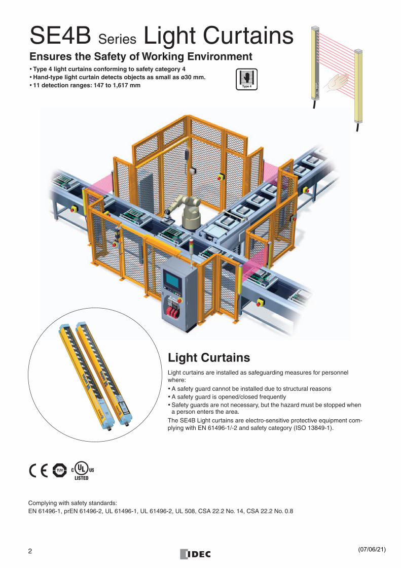
SE4B Series Light CurtainsEnsures the Safety of Working Environment• Type 4 light curtains conforming to safety category 4• Hand-type light curtain detects objects as small as ø30 mm.• 11 detection ranges: 147 to 1,617 mm
Light CurtainsLight curtains are installed as safeguarding measures for personnel where:• A safety guard cannot be installed due to structural reasons• A safety guard is opened/closed frequently• Safety guards are not necessary, but the hazard must be stopped when
a person enters the area.The SE4B Light curtains are electro-sensitive protective equipment com-plying with EN 61496-1/-2 and safety category (ISO 13849-1).
Complying with safety standards:EN 61496-1, prEN 61496-2, UL 61496-1, UL 61496-2, UL 508, CSA 22.2 No. 14, CSA 22.2 No. 0.8
Type 4
(07/06/21)
3
•
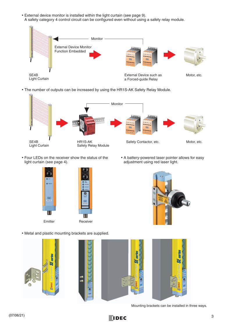
External device monitor is installed within the light curtain (see page 9).A safety category 4 control circuit can be configured even without using a safety relay module.
•
The number of outputs can be increased by using the HR1S-AK Safety Relay Module.
•
Metal and plastic mounting brackets are supplied.
External Device such asa Forced-guide Relay
Monitor
External Device MonitorFunction Embedded
SE4BLight Curtain
Motor, etc.
Monitor
Safety Contactor, etc.HR1S-AKSafety Relay Module
SE4BLight Curtain
Motor, etc.
• Four LEDs on the receiver show the status of the light curtain (see page 4).
• A battery-powered laser pointer allows for easy adjustment using red laser light.
Emitter Receiver
Mounting brackets can be installed in three ways.
(07/06/21)
4
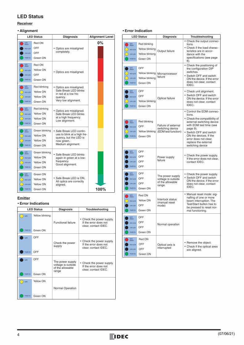
LED Status
Receiver
• Alignment
Emitter• Error Indications
• Error Indication
LED Status Diagnosis Alignment Level
• Optics are misaligned completely.
• Optics are misaligned.
• Optics are misaligned. Safe Break LED blinks in red at a low fre-quency.Very low alignment.
• Optics are misaligned. Safe Break LED blinks at a high frequency.Low alignment.
• Safe Break LED contin-ues to blink at a high fre-quency, but the LED is now green.Medium alignment.
• Safe Break LED blinks again in green at a low-frequency.Good alignment.
• Safe Break LED is ON.All optics are correctly aligned.
LED Status Diagnosis Troubleshooting
Functional failure• Check the power supply.
If the error does not clear, contact IDEC.
Check the power supply
• Check the power supply.If the error does not clear, contact IDEC.
The power supply voltage is outside of the allowable range
• Check the power supply.If the error does not clear, contact IDEC.
Normal Operation
Red ON
OFF
OFF
Green ON
Red ON
Yellow ON
OFF
Green ON
Red blinking
Yellow ON
Yellow ON
Green ON
Red blinking
Yellow ON
Yellow ON
Green ON
Green blinking
Yellow ON
Yellow ON
Green ON
Green blinking
Yellow ON
Yellow ON
Green ON
Green ON
Yellow ON
Yellow ON
Green ON
Yellow blinking
Green ON
OFF
OFF
OFF
Green ON
Yellow ON
Green ON
LED Status Diagnosis Troubleshooting
Output failure
• Check the output connec-tions.
• Check if the load charac-teristics are in accor-dance with the specifications (see page 6).
Microprocessor failure
• Check the positioning of the configuration DIP switches.
• Switch OFF and switch ON the device. If the error does not clear, contact IDEC.
Optical failure
• Check unit alignment.• Switch OFF and switch
ON the device. If the error does not clear, contact IDEC.
Failure of external switching device (EDM test function)
• Control the EDM connec-tions.
• Check the compatibility of external switching device with EDM test time (see page 9).
• Switch OFF and switch ON the devices. If the error does not clear, replace the external switching device
Power supplyfailure
• Check the power supply. If the error does not clear, contact IDEC.
The power supply voltage is outside of the allowable range.
• Check the power supply.• Switch OFF and switch
ON the device. if the error does not clear, contact IDEC.
Interlock status (manual reset mode)
• Manual reset mode: sig-nalling of one or more beam interruption. The Test/Start button has to be pressed to reset nor-mal functioning.
Normal operation
Optical axis is interrupted
• Remove the object.• Check if the optical axes
are aligned.
Red blinking
Yellow blinking
Yellow blinking
Green ON
OFF
Yellow blinking
Yellow blinking
Green ON
OFF
OFF
Yellow blinking
Green ON
Red blinking
OFF
Yellow blinking
Green ON
OFF
OFF
OFF
OFF
OFF
OFF
OFF
Green ON
Red ON
Yellow ON
OFF
Green ON
OFF
OFF
OFF
Green ON
Red ON
OFF
OFF
Green ON
(07/06/21)
5
SE4B
Series
Light Curtains
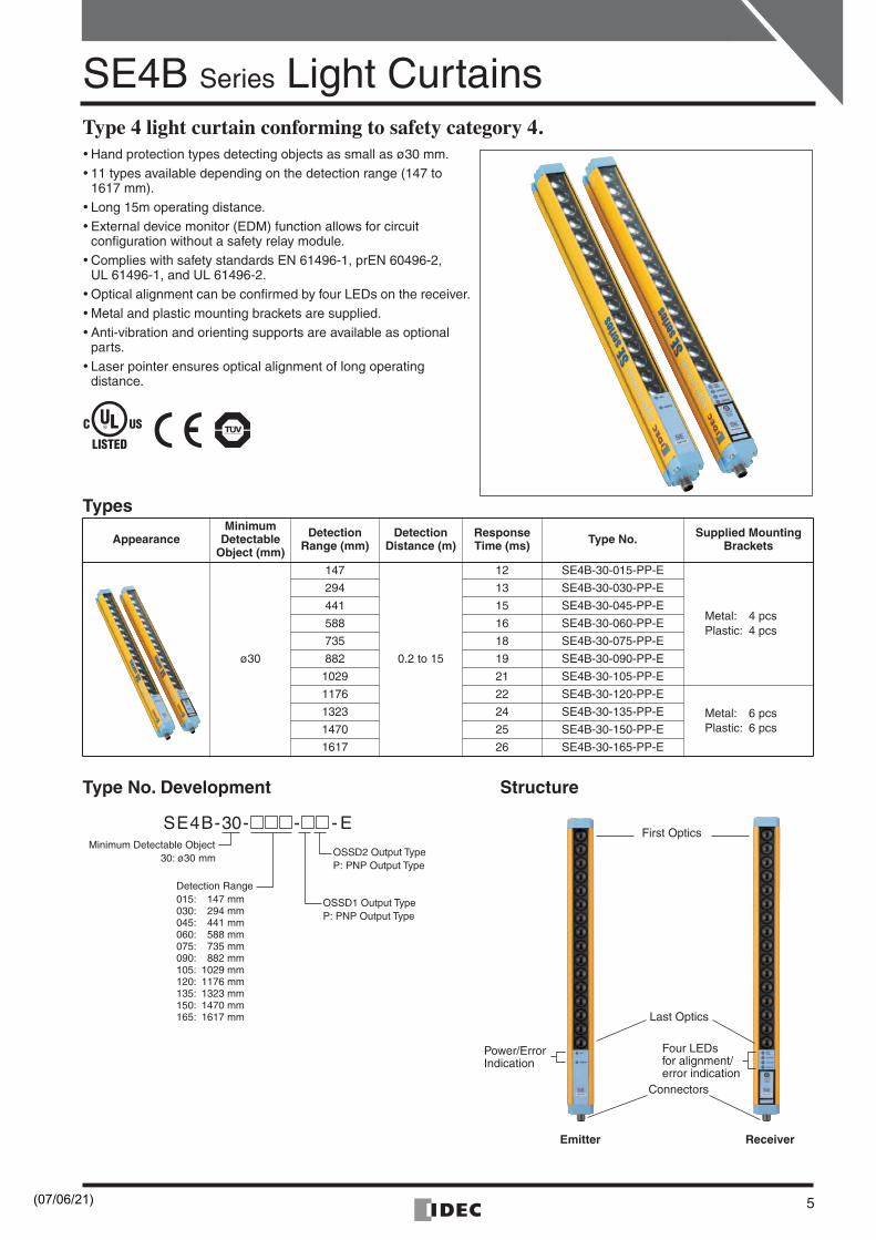
Type 4 light curtain conforming to safety category 4.
•
Hand protection types detecting objects as small as ø30 mm.
•
11 types available depending on the detection range (147 to 1617 mm).
•
Long 15m operating distance.
•
External device monitor (EDM) function allows for circuitconfiguration without a safety relay module.
•
Complies with safety standards EN 61496-1, prEN 60496-2,UL 61496-1, and UL 61496-2.
•
Optical alignment can be confirmed by four LEDs on the receiver.
•
Metal and plastic mounting brackets are supplied.
•
Anti-vibration and orienting supports are available as optional parts.
•
Laser pointer ensures optical alignment of long operatingdistance.
Types
Type No. Development Structure
AppearanceMinimum
DetectableObject (mm)
DetectionRange (mm)
DetectionDistance (m)
ResponseTime (ms) Type No. Supplied Mounting
Brackets
ø30
147
0.2 to 15
12 SE4B-30-015-PP-E
Metal: 4 pcsPlastic: 4 pcs
294 13 SE4B-30-030-PP-E
441 15 SE4B-30-045-PP-E
588 16 SE4B-30-060-PP-E
735 18 SE4B-30-075-PP-E
882 19 SE4B-30-090-PP-E
1029 21 SE4B-30-105-PP-E
1176 22 SE4B-30-120-PP-E
Metal: 6 pcsPlastic: 6 pcs
1323 24 SE4B-30-135-PP-E
1470 25 SE4B-30-150-PP-E
1617 26 SE4B-30-165-PP-E
First Optics
Last Optics
Connectors
Emitter Receiver
Four LEDsfor alignment/error indication
Power/ErrorIndication
SE4B-30- - - EMinimum Detectable Object
30: ø30 mm
Detection Range015: 147 mm030: 294 mm045: 441 mm060: 588 mm075: 735 mm090: 882 mm105: 1029 mm120: 1176 mm135: 1323 mm150: 1470 mm165: 1617 mm
OSSD2 Output TypeP: PNP Output Type
OSSD1 Output TypeP: PNP Output Type
(07/06/21)
SE4B
Series
Light Curtains
6
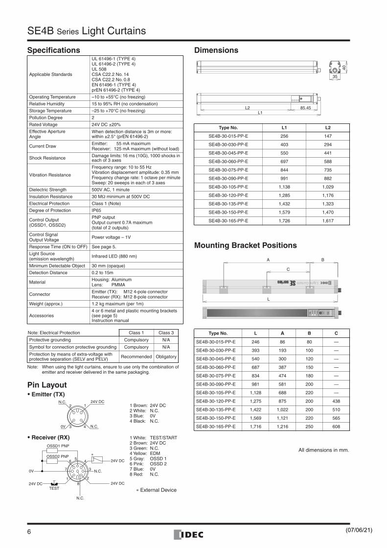
Specifications
Note: When using the light curtains, ensure to use only the combination of emitter and receiver delivered in the same packaging.
Pin Layout
Dimensions
Mounting Bracket Positions
Applicable Standards
UL 61496-1 (TYPE 4)UL 61496-2 (TYPE 4)UL 508CSA C22.2 No. 14CSA C22.2 No. 0.8EN 61496-1 (TYPE 4)prEN 61496-2 (TYPE 4)
Operating Temperature –10 to +55°C (no freezing)
Relative Humidity 15 to 95% RH (no condensation)
Storage Temperature –25 to +70°C (no freezing)
Pollution Degree 2
Rated Voltage 24V DC ±20%
Effective ApertureAngle
When detection distance is 3m or more:within ±2.5° (prEN 61496-2)
Current Draw Emitter: 55 mA maximumReceiver: 125 mA maximum (without load)
Shock Resistance Damage limits: 16 ms (10G), 1000 shocks in each of 3 axes
Vibration Resistance
Frequency range: 10 to 55 HzVibration displacement amplitude: 0.35 mmFrequency change rate: 1 octave per minuteSweep: 20 sweeps in each of 3 axes
Dielectric Strength 500V AC, 1 minute
Insulation Resistance 30 M
Ω
minimum at 500V DC
Electrical Protection Class 1 (Note)
Degree of Protection IP65
Control Output(OSSD1, OSSD2)
PNP outputOutput current 0.7A maximum(total of 2 outputs)
Control SignalOutput Voltage Power voltage – 1V
Response Time (ON to OFF) See page 5.
Light Source(emission wavelength) Infrared LED (880 nm)
Minimum Detectable Object 30 mm (opaque)
Detection Distance 0.2 to 15m
Material Housing: AluminumLens: PMMA
Connector Emitter (TX): M12 4-pole connectorReceiver (RX): M12 8-pole connector
Weight (approx.) 1.2 kg maximum (per 1m)
Accessories4 or 6 metal and plastic mounting brackets (see page 5)Instruction manual
Note: Electrical Protection Class 1 Class 3
Protective grounding Compulsory N/A
Symbol for connection protective grounding Compulsory N/A
Protection by means of extra-voltage with protective separation (SELV and PELV) Recommended Obligatory
3 4
2 1N.C.
0V
24V DC
N.C.
28
1
5
3
4
7
6
24V DC
24V DC
0V
OSSD1 PNP
OSSD2 PNP
N.C.
N.C.
24V DCTEST
∗
1 Brown: 24V DC2 White: N.C.3 Blue: 0V4 Black: N.C.
1 White: TEST/START2 Brown: 24V DC3 Green: N.C.4 Yellow: EDM5 Gray: OSSD 16 Pink: OSSD 27 Blue: 0V8 Red: N.C.
•••• Emitter (TX)
•••• Receiver (RX)
∗ External Device
Type No. L1 L2
SE4B-30-015-PP-E 256 147
SE4B-30-030-PP-E 403 294
SE4B-30-045-PP-E 550 441
SE4B-30-060-PP-E 697 588
SE4B-30-075-PP-E 844 735
SE4B-30-090-PP-E 991 882
SE4B-30-105-PP-E 1,138 1,029
SE4B-30-120-PP-E 1,285 1,176
SE4B-30-135-PP-E 1,432 1,323
SE4B-30-150-PP-E 1,579 1,470
SE4B-30-165-PP-E 1,726 1,617
Type No. L
A
B C
SE4B-30-015-PP-E 246 86 80 —
SE4B-30-030-PP-E 393 193 100 —
SE4B-30-045-PP-E 540 300 120 —
SE4B-30-060-PP-E 687 387 150 —
SE4B-30-075-PP-E 834 474 180 —
SE4B-30-090-PP-E 981 581 200 —
SE4B-30-105-PP-E 1,128 688 220 —
SE4B-30-120-PP-E 1,275 875 200 438
SE4B-30-135-PP-E 1,422 1,022 200 510
SE4B-30-150-PP-E 1,569 1,121 220 565
SE4B-30-165-PP-E 1,716 1,216 250 608
L1
40
35
85.45L2
A B
C
L
All dimensions in mm.
(07/06/21)
SE4B
Series
Light Curtains
7
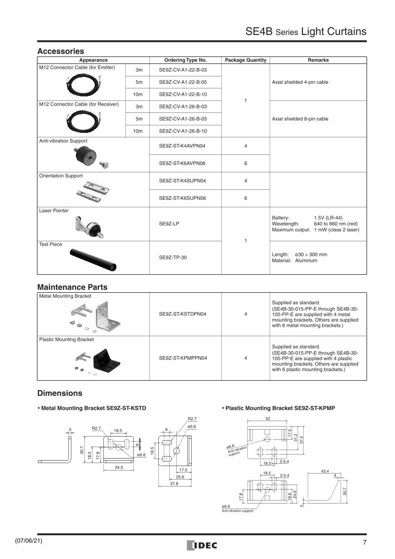
Accessories
Maintenance Parts
Dimensions
Appearance Ordering Type No. Package Quantity Remarks
M12 Connector Cable (for Emitter) 3m SE9Z-CV-A1-22-B-03
1
Axial shielded 4-pin cable5m SE9Z-CV-A1-22-B-05
10m SE9Z-CV-A1-22-B-10
M12 Connector Cable (for Receiver) 3m SE9Z-CV-A1-26-B-03
Axial shielded 8-pin cable5m SE9Z-CV-A1-26-B-05
10m SE9Z-CV-A1-26-B-10
Anti-vibration SupportSE9Z-ST-K4AVPN04 4
SE9Z-ST-K6AVPN06 6
Orientation SupportSE9Z-ST-K4SUPN04 4
SE9Z-ST-K6SUPN06 6
Laser Pointer
SE9Z-LP
1
Battery: 1.5V (LR-44)Wavelength: 640 to 660 nm (red)Maximum output: 1 mW (class 2 laser)
Test Piece
SE9Z-TP-30Length: ø30
×
300 mmMaterial: Aluminum
Metal Mounting Bracket
SE9Z-ST-KSTDPN04 4
Supplied as standard.(SE4B-30-015-PP-E through SE4B-30-105-PP-E are supplied with 4 metal mounting brackets. Others are supplied with 6 metal mounting brackets.)
Plastic Mounting Bracket
SE9Z-ST-KPMPPN04 4
Supplied as standard.(SE4B-30-015-PP-E through SE4B-30-105-PP-E are supplied with 4 plastic mounting brackets. Others are supplied with 6 plastic mounting brackets.)
6
37.8
R2.7
18.5
25.6
17.5
ø6.6
ø6.6
34.5
18.5
30.7
18.5
6
R2.7
17.8
3
43.4
30.7
4
42-5.418.5
18.6
17.8 24
.6
52
2-5.418.5
17.5
31.2
37.2
Anti-vibration
support
Anti-vibration support
• Plastic Mounting Bracket SE9Z-ST-KPMP• Metal Mounting Bracket SE9Z-ST-KSTD
ø6.6
ø6.6
(07/06/21)
SE4B
Series
Light Curtains
8
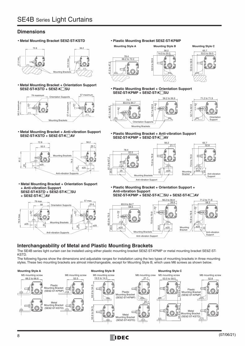
Dimensions
Interchangeability of Metal and Plastic Mounting Brackets
The SE4B series light curtain can be installed using either plastic mounting bracket SE9Z-ST-KPMP or metal mounting bracket SE9Z-ST-KSTD.The following figures show the dimensions and adjustable ranges for installation using the two types of mounting brackets in three mounting styles. These two mounting brackets are almost interchangeable, except for Mounting Style B, which uses M6 screws as shown below.
78.4
41.2
to 4
7.2
66.2 to 72.2
56.214.5 to 20.5
53.9
to 5
9.9
65.753.5 to 59.5
53.9
to 5
9.9
Mounting Style A Mounting Style B Mounting Style C
±5
52.7
to 6
2.9
56.2 to 56.9
±5
74.7
40.1
to 5
0.3
83.9 to 84.7
±5
52.7
to 6
2.9
71.2 to 71.9
78.452.5
20.0 ¯25
61.2
to 6
7.2
56.221.1
20.0 ø25
73.9
to 7
9.9
20
52.865.7
ø25
73.9
to 7
9.9
26.6
ø25
20.0
±5
73.9
to 7
9.9
56.2 to 56.9
±5
2058.3
ø25
73.9
to 7
9.9
71.2 to 71.9
58.0
ø25
20.0
±5
60.0
to 7
0.3
83.9 to 84.7
Mounting Brackets
Mounting Brackets
MountingBracket
Orientation Supports
OrientationSupport
MountingBracket
Anti-vibration Support
Anti-vibrationSupport
Mounting Brackets
Anti-vibration Support
Anti-vibrationSupport
72.8
41.2
min
.
56.2
54.3
max
.
Mounting Brackets
52.5
61.2
72.8
ø25
20
Anti-vibration Supports
Mounting Brackets
74.3
56.2
ø2520
20.1
79 maximum
50.2
max
imum
Mounting Brackets
Orientation Supports
57.4
max
imum
57 maximum
±5°
±5°
79 max.
72.9
max
.
ø25
20
58
±5°
Mounting Brackets
Anti-vibration Supports
Orientation Supports
57 max..
79.8
max
.
20
ø25
±5°
25.6
• Metal Mounting Bracket SE9Z-ST-KSTD
• Metal Mounting Bracket + Anti-vibration SupportSE9Z-ST-KSTD + SE9Z-ST-K AV
• Metal Mounting Bracket + Orientation Support+ Anti-vibration SupportSE9Z-ST-KSTD + SE9Z-ST-K SU+ SE9Z-ST-K AV
• Metal Mounting Bracket + Orientation SupportSE9Z-ST-KSTD + SE9Z-K SU
• Plastic Mounting Bracket SE9Z-ST-KPMP
• Plastic Mounting Bracket + Orientation SupportSE9Z-ST-KPMP + SE9Z-ST-K SU
• Plastic Mounting Bracket + Anti-vibration SupportSE9Z-ST-KPMP + SE9Z-ST-K AV
• Plastic Mounting Bracket + Orientation Support +Anti-vibration SupportSE9Z-ST-KPMP + SE9Z-ST-K SU + SE9Z-ST-K AV
53.9
to 5
4.3
53.9
to 5
4.3
20.1
21.119.5 to 14.5
Mounting Style B
PlasticMounting Bracket (SE9Z-ST-KPMP)
MetalMounting Bracket (SE9Z-ST-KSTD)
M6 mounting crew52.566.2 to 66.6
Mounting Style A
PlasticMounting Bracket (SE9Z-ST-KPMP)
MetalMounting Bracket (SE9Z-ST-KSTD)
M6 mounting screwM5 mounting screw M5 mounting screw
Mounting Style CM6 mounting screwM5 mounting screw
MetalMounting Bracket (SE9Z-ST-KSTD)
52.853.5 to 59.5
53.9
to 5
4.3
53.9
to 5
4.3
PlasticMounting Bracket (SE9Z-ST-KPMP)
(07/06/21)
SE4B
Series
Light Curtains
9
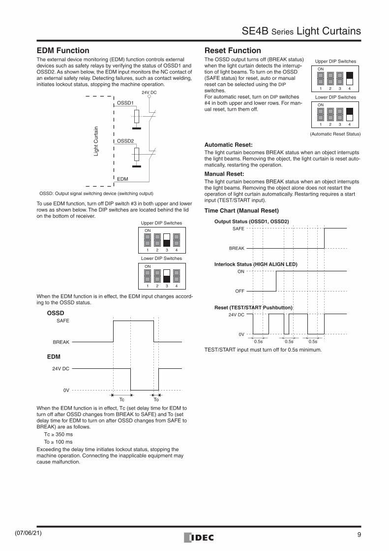
EDM FunctionThe external device monitoring (EDM) function controls external devices such as safety relays by verifying the status of OSSD1 and OSSD2. As shown below, the EDM input monitors the NC contact of an external safety relay. Detecting failures, such as contact welding, initiates lockout status, stopping the machine operation.
To use EDM function, turn off DIP switch #3 in both upper and lower rows as shown below. The DIP switches are located behind the lid on the bottom of receiver.
When the EDM function is in effect, the EDM input changes accord-ing to the OSSD status.
When the EDM function is in effect, Tc (set delay time for EDM to turn off after OSSD changes from BREAK to SAFE) and To (set delay time for EDM to turn on after OSSD changes from SAFE to BREAK) are as follows.
Tc ≥ 350 msTo ≥ 100 ms
Exceeding the delay time initiates lockout status, stopping the machine operation. Connecting the inapplicable equipment may cause malfunction.
Reset FunctionThe OSSD output turns off (BREAK status) when the light curtain detects the interrup-tion of light beams. To turn on the OSSD (SAFE status) for reset, auto or manual reset can be selected using the DIP switches.For automatic reset, turn on DIP switches #4 in both upper and lower rows. For man-ual reset, turn them off.
Automatic Reset:The light curtain becomes BREAK status when an object interrupts the light beams. Removing the object, the light curtain is reset auto-matically, restarting the operation.
Manual Reset:The light curtain becomes BREAK status when an object interrupts the light beams. Removing the object alone does not restart the operation of light curtain automatically. Restarting requires a start input (TEST/START input).
Time Chart (Manual Reset)
TEST/START input must turn off for 0.5s minimum.
24V DCLi
ght C
urta
in
EDM
OSSD2
OSSD1
OSSD: Output signal switching device (switching output)
ON
1 2 3 4
ON
1 2 3 4
Upper DIP Switches
Lower DIP Switches
OSSDSAFE
BREAK
24V DC
0V
Tc To
EDM
ON
1 2 3 4
ON
1 2 3 4
Upper DIP Switches
Lower DIP Switches
(Automatic Reset Status)
Output Status (OSSD1, OSSD2)SAFE
BREAK
Interlock Status (HIGH ALIGN LED)ON
OFF
Reset (TEST/START Pushbutton)24V DC
0V
0.5s 0.5s 0.5s
(07/06/21)
SE4B Series Light Curtains
10
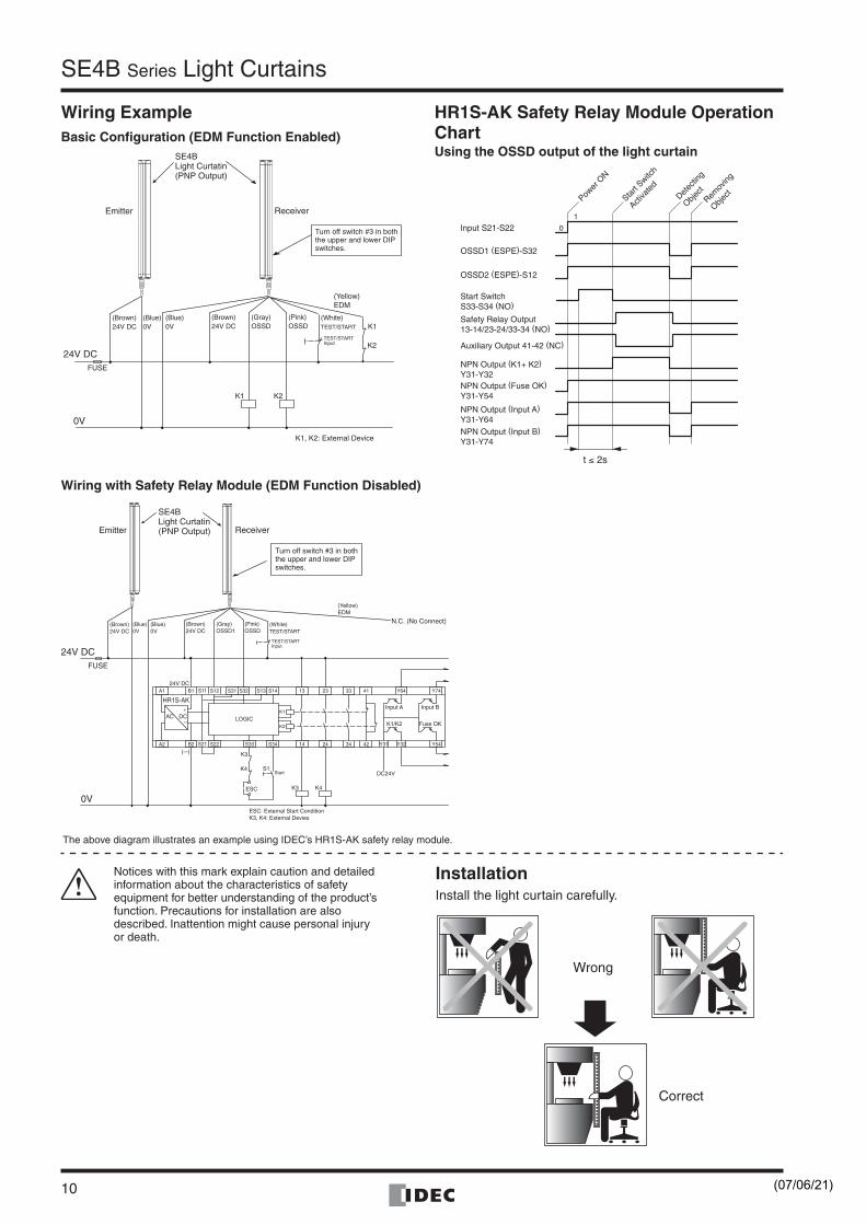
Wiring ExampleBasic Configuration (EDM Function Enabled)
HR1S-AK Safety Relay Module Operation ChartUsing the OSSD output of the light curtain
Wiring with Safety Relay Module (EDM Function Disabled)
24V DC
K1 K2
K1
K2
FUSE
SE4BLight Curtatin(PNP Output)
(Brown)24V DC
(Blue)0V
(Brown)24V DC
(White)TEST/START
TEST/STARTInput
(Gray)OSSD
(Blue)0V
(Pink)OSSD
(Yellow)EDM
ReceiverEmitter
0V
K1, K2: External Device
Turn off switch #3 in both the upper and lower DIP switches.
t ≤ 2s
OSSD2 (ESPE)-S12
Start SwitchS33-S34 (NO)
Safety Relay Output13-14/23-24/33-34 (NO)
Auxiliary Output 41-42 (NC)
NPN Output (K1+ K2)Y31-Y32NPN Output (Fuse OK)Y31-Y54
NPN Output (Input A)Y31-Y64NPN Output (Input B)Y31-Y74
Input S21-S22
OSSD1 (ESPE)-S32
Power
ON
Start
Switch
Activa
ted
Detec
ting
Object
Remov
ing
Object
0
1
ESC
A1 B1 S12 S31 S32 S13 S14 13 23 33 41 Y64 Y74
A2 S22 S33 S34 14 24 34 42 Y31 Y32 Y54B2
Input A Input B
K1/K2 Fuse OK
DC24V
K3 K4
S1
K3
K4
(–)
LOGIC
+
–AC DC
HR1S-AK
K1
K2
24V DC
(Brown)24V DC
(Blue)0V
(Brown)24V DC
(White)TEST/START
TEST/STARTInput
(Gray)OSSD1
(Blue)0V
(Pink)OSSD
(Yellow)EDM
N.C. (No Connect)
Start
S11
S21
ESC: External Start ConditionK3, K4: External Devies
24V DC FUSE
SE4BLight Curtatin(PNP Output) ReceiverEmitter
0V
Turn off switch #3 in both the upper and lower DIP switches.
Notices with this mark explain caution and detailed information about the characteristics of safety equipment for better understanding of the product’s function. Precautions for installation are also described. Inattention might cause personal injury or death.
Wrong
Correct
InstallationInstall the light curtain carefully.
The above diagram illustrates an example using IDEC’s HR1S-AK safety relay module.
(07/06/21)
SE4B Series Light Curtains
11
Wrong Correct
0 1 2 3 4 5 6 7 8 9 10 11 12 13 14 15 16
800
700
600
500
400
300
200
100
0
Sensing Distance (m)
Min
imum
Dis
tanc
e to
the
Ref
lect
ive
Sur
face
(m
m)
Hazardous Area
Emitter
Reflective Surface
Receiverd
α
α
α
α
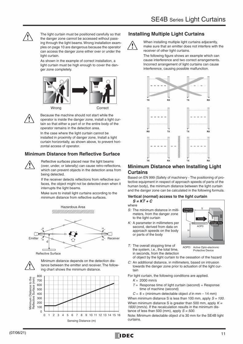
Because the machine should not start while the operator is inside the danger zone, install a light cur-tain so that either a part of or the entire body of the operator remains in the detection area.
In the case where the light curtain cannot be installed in proximity of danger zone, Install a light curtain horizontally, as shown above, to prevent hori-zontal access of operator.
The light curtain must be positioned carefully so that the danger zone cannot be accessed without pass-ing through the light beams. Wrong installation exam-ples on page 10 are dangerous because the operator can access the danger zone either over or under the light curtain.
As shown in the example of correct installation, a light curtain must be high enough to cover the dan-ger zone completely.
Reflective surfaces placed near the light beams (over, under, or laterally) can cause retro-reflections, which can prevent objects in the detection area from being detected.
If the receiver detects reflections from reflective sur-faces, the object might not be detected even when it interrupts the light beams.
Make sure to install light curtains according to the minimum distance from reflective surfaces.
Minimum Distance from Reflective Surface
Minimum distance depends on the detection dis-tance between the emitter and receiver. The follow-ing chart shows the minimum distance.
Installing Multiple Light Curtains
When installing multiple light curtains adjacently, make sure that an emitter does not interfere with the receiver of other light curtains.
The following figure shows an example which can cause interference and two correct arrangements. Incorrect arrangement of light curtains can cause interference, causing possible malfunction.
Minimum Distance when Installing Light CurtainsBased on EN 999 (Safety of machinery - The positioning of pro-tective equipment in respect of approach speeds of parts of the human body), the minimum distance between the light curtain and the danger zone can be calculated in the following formula.
Vertical (normal) access to the light curtainS = KT + C
whereS: The minimum distance in milli-
meters, from the danger zone to the light curtain
K: A parameter in millimeters per second, derived from data on approach speeds on the body or parts of the body
T: The overall stopping time of the system, i.e., the total time, in seconds, from the detectionof object by the light curtain to the cessation of the hazard
C: An additional distance, in millimeters, based on intrusion towards the danger zone prior to actuation of the light cur-tain
For light curtain, the following conditions are applied.K = 2000 mm/sT = Response time of light curtain (second) + Response
time of machine (second)C = 8 × (minimum detectable object d in mm – 14 mm)
When minimum distance S is less than 100 mm, apply S = 100.When minimum distance S is greater than 500 mm, apply K = 1600 (mm/s). If the recalculation results in the minimum dis-tance of less than 500 (mm), apply S = 500.Note: Minimum detectable object d is 30 mm for the SE4B light curtains.
AOPD
S
H
Danger Zone
Access
ProtectiveArea Limit
AOPD: Active Opto-electronicProtective Device
(07/06/21)
SE4B Series Light Curtains
12
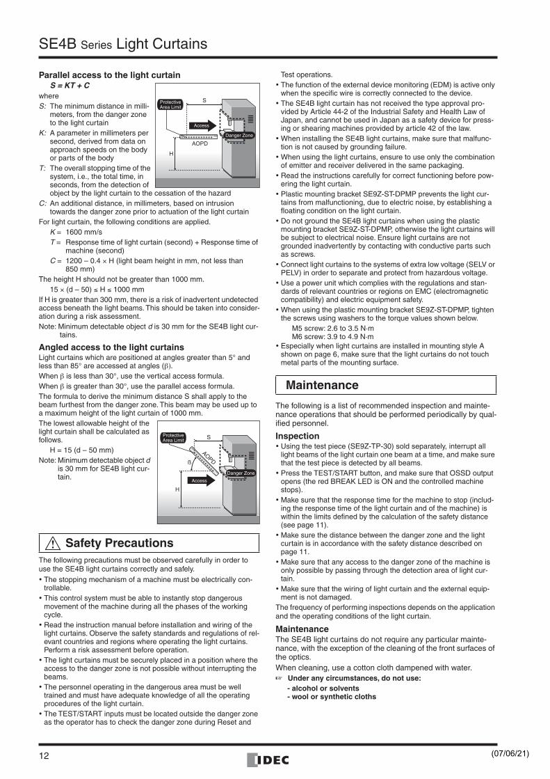
Parallel access to the light curtainS = KT + C
whereS: The minimum distance in milli-
meters, from the danger zone to the light curtain
K: A parameter in millimeters per second, derived from data on approach speeds on the body or parts of the body
T: The overall stopping time of the system, i.e., the total time, in seconds, from the detection of object by the light curtain to the cessation of the hazard
C: An additional distance, in millimeters, based on intrusion towards the danger zone prior to actuation of the light curtain
For light curtain, the following conditions are applied.K = 1600 mm/sT = Response time of light curtain (second) + Response time of
machine (second)C = 1200 – 0.4 × H (light beam height in mm, not less than
850 mm)The height H should not be greater than 1000 mm.
15 × (d – 50) ≤ H ≤ 1000 mmIf H is greater than 300 mm, there is a risk of inadvertent undetected access beneath the light beams. This should be taken into consider-ation during a risk assessment.Note: Minimum detectable object d is 30 mm for the SE4B light cur-
tains.
Angled access to the light curtainsLight curtains which are positioned at angles greater than 5° and less than 85° are accessed at angles (β).When β is less than 30°, use the vertical access formula.When β is greater than 30°, use the parallel access formula.The formula to derive the minimum distance S shall apply to the beam furthest from the danger zone. This beam may be used up to a maximum height of the light curtain of 1000 mm.The lowest allowable height of the light curtain shall be calculated as follows.
H = 15 (d – 50 mm)Note: Minimum detectable object d
is 30 mm for SE4B light cur-tain.
The following precautions must be observed carefully in order to use the SE4B light curtains correctly and safely.• The stopping mechanism of a machine must be electrically con-
trollable.• This control system must be able to instantly stop dangerous
movement of the machine during all the phases of the working cycle.
• Read the instruction manual before installation and wiring of the light curtains. Observe the safety standards and regulations of rel-evant countries and regions where operating the light curtains. Perform a risk assessment before operation.
• The light curtains must be securely placed in a position where the access to the danger zone is not possible without interrupting the beams.
• The personnel operating in the dangerous area must be well trained and must have adequate knowledge of all the operating procedures of the light curtain.
• The TEST/START inputs must be located outside the danger zone as the operator has to check the danger zone during Reset and
Test operations.• The function of the external device monitoring (EDM) is active only
when the specific wire is correctly connected to the device.• The SE4B light curtain has not received the type approval pro-
vided by Article 44-2 of the Industrial Safety and Health Law of Japan, and cannot be used in Japan as a safety device for press-ing or shearing machines provided by article 42 of the law.
• When installing the SE4B light curtains, make sure that malfunc-tion is not caused by grounding failure.
• When using the light curtains, ensure to use only the combination of emitter and receiver delivered in the same packaging.
• Read the instructions carefully for correct functioning before pow-ering the light curtain.
• Plastic mounting bracket SE9Z-ST-DPMP prevents the light cur-tains from malfunctioning, due to electric noise, by establishing a floating condition on the light curtain.
• Do not ground the SE4B light curtains when using the plastic mounting bracket SE9Z-ST-DPMP, otherwise the light curtains will be subject to electrical noise. Ensure light curtains are not grounded inadvertently by contacting with conductive parts such as screws.
• Connect light curtains to the systems of extra low voltage (SELV or PELV) in order to separate and protect from hazardous voltage.
• Use a power unit which complies with the regulations and stan-dards of relevant countries or regions on EMC (electromagnetic compatibility) and electric equipment safety.
• When using the plastic mounting bracket SE9Z-ST-DPMP, tighten the screws using washers to the torque values shown below.
M5 screw: 2.6 to 3.5 N·mM6 screw: 3.9 to 4.9 N·m
• Especially when light curtains are installed in mounting style A shown on page 6, make sure that the light curtains do not touch metal parts of the mounting surface.
The following is a list of recommended inspection and mainte-nance operations that should be performed periodically by qual-ified personnel.
Inspection• Using the test piece (SE9Z-TP-30) sold separately, interrupt all
light beams of the light curtain one beam at a time, and make sure that the test piece is detected by all beams.
• Press the TEST/START button, and make sure that OSSD output opens (the red BREAK LED is ON and the controlled machine stops).
• Make sure that the response time for the machine to stop (includ-ing the response time of the light curtain and of the machine) is within the limits defined by the calculation of the safety distance (see page 11).
• Make sure the distance between the danger zone and the light curtain is in accordance with the safety distance described on page 11.
• Make sure that any access to the danger zone of the machine is only possible by passing through the detection area of light cur-tain.
• Make sure that the wiring of light curtain and the external equip-ment is not damaged.
The frequency of performing inspections depends on the application and the operating conditions of the light curtain.
MaintenanceThe SE4B light curtains do not require any particular mainte-nance, with the exception of the cleaning of the front surfaces of the optics.When cleaning, use a cotton cloth dampened with water.☞ Under any circumstances, do not use:
- alcohol or solvents- wool or synthetic cloths
Safety Precautions
AOPD
S
H
Danger Zone
Access
ProtectiveArea Limit
AOPD
S
H
ß
Access
Danger Zone
ProtectiveArea Limit
Maintenance
(07/06/21)
SE4B Series Light Curtains
13
Optical Axes Alignment Procedures
Notes on Operating Environment
General Information☞ The light curtains achieve their safety function only when they
are installed correctly in accordance with the standards and reg-ulations in effect. If there is no expertise to install the light cur-tains correctly, contact IDEC.
In the event of short-circuit, the light curtains are protected by auto-resetting type fuses.After the fuse is blown, turn off the power supply and wait for 20 sec-onds. The fuse restarts automatically, starting the operation of light curtain.A power failure caused by interferences may cause the opening of outputs temporarily, but the safety function of light curtains will not be lost.
WarrantyThe SE4B light curtains are under a 1 year warranty from the ship date. IDEC will not be liable for any damages to persons or proper-ties caused by non-observance of the installation and operating instructions.The warranty will not cover damages caused by incorrect installa-tion, incorrect use and accidental causes such as bumps or falls.In the event the SE4B light curtains do not function properly, return the emitter and receiver for repair or replacement.☞ In case the SE4B light curtains should fail, contact IDEC.
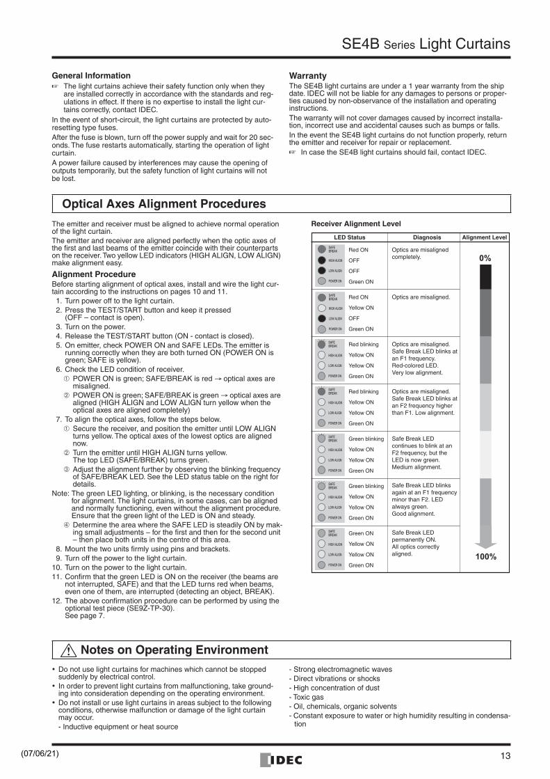
The emitter and receiver must be aligned to achieve normal operation of the light curtain.The emitter and receiver are aligned perfectly when the optic axes of the first and last beams of the emitter coincide with their counterparts on the receiver. Two yellow LED indicators (HIGH ALIGN, LOW ALIGN) make alignment easy.
Alignment ProcedureBefore starting alignment of optical axes, install and wire the light cur-tain according to the instructions on pages 10 and 11. 1. Turn power off to the light curtain.2. Press the TEST/START button and keep it pressed
(OFF – contact is open).3. Turn on the power.4. Release the TEST/START button (ON - contact is closed).5. On emitter, check POWER ON and SAFE LEDs. The emitter is
running correctly when they are both turned ON (POWER ON is green; SAFE is yellow).
6. Check the LED condition of receiver.➀ POWER ON is green; SAFE/BREAK is red → optical axes are
misaligned.➁ POWER ON is green; SAFE/BREAK is green → optical axes are
aligned (HIGH ALIGN and LOW ALIGN turn yellow when the optical axes are aligned completely)
7. To align the optical axes, follow the steps below.➀ Secure the receiver, and position the emitter until LOW ALIGN
turns yellow. The optical axes of the lowest optics are aligned now.
➁ Turn the emitter until HIGH ALIGN turns yellow.The top LED (SAFE/BREAK) turns green.
➂ Adjust the alignment further by observing the blinking frequency of SAFE/BREAK LED. See the LED status table on the right for details.
Note: The green LED lighting, or blinking, is the necessary condition for alignment. The light curtains, in some cases, can be aligned and normally functioning, even without the alignment procedure. Ensure that the green light of the LED is ON and steady.
➃ Determine the area where the SAFE LED is steadily ON by mak-ing small adjustments – for the first and then for the second unit – then place both units in the centre of this area.
8. Mount the two units firmly using pins and brackets.9. Turn off the power to the light curtain.
10. Turn on the power to the light curtain.11. Confirm that the green LED is ON on the receiver (the beams are
not interrupted, SAFE) and that the LED turns red when beams, even one of them, are interrupted (detecting an object, BREAK).
12. The above confirmation procedure can be performed by using the optional test piece (SE9Z-TP-30).See page 7.
LED Status Diagnosis Alignment Level
Red ON
OFF
OFF
Green ON
Red ON
Yellow ON
OFF
Green ON
Red blinking
Yellow ON
Yellow ON
Green ON
Red blinking
Yellow ON
Yellow ON
Green ON
Green blinking
Yellow ON
Yellow ON
Green ON
Green blinking
Yellow ON
Yellow ON
Green ON
Green ON
Yellow ON
Yellow ON
Green ON
Optics are misaligned completely.
Optics are misaligned.
Optics are misaligned. Safe Break LED blinks at an F1 frequency. Red-colored LED.Very low alignment.
Optics are misaligned. Safe Break LED blinks at an F2 frequency higher than F1. Low alignment.
Safe Break LED continues to blink at an F2 frequency, but the LED is now green.Medium alignment.
Safe Break LED blinks again at an F1 frequency minor than F2. LED always green.Good alignment.
Safe Break LED permanently ON.All optics correctly aligned.
Receiver Alignment Level
• Do not use light curtains for machines which cannot be stopped suddenly by electrical control.
• In order to prevent light curtains from malfunctioning, take ground-ing into consideration depending on the operating environment.
• Do not install or use light curtains in areas subject to the following conditions, otherwise malfunction or damage of the light curtain may occur.- Inductive equipment or heat source
- Strong electromagnetic waves- Direct vibrations or shocks- High concentration of dust- Toxic gas- Oil, chemicals, organic solvents- Constant exposure to water or high humidity resulting in condensa-
tion
(07/06/21)
SE4B Series Light Curtains
14
HR1S Series Safety Relay Modules
Dimensions
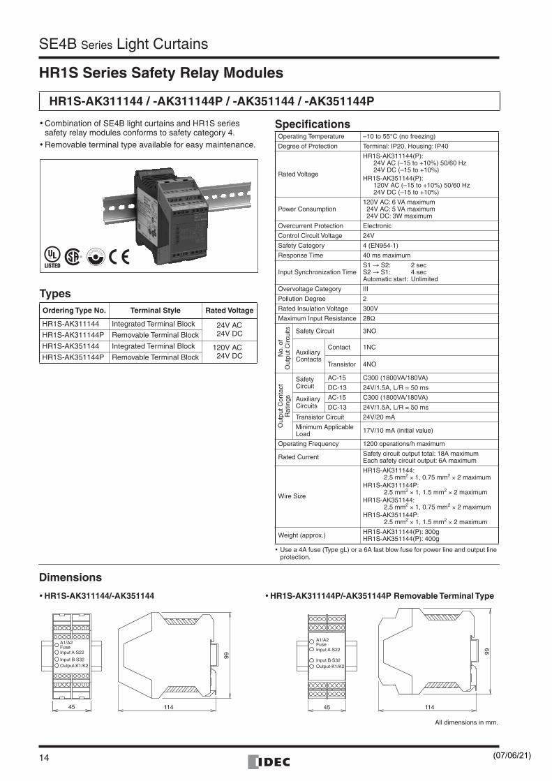
HR1S-AK311144 / -AK311144P / -AK351144 / -AK351144P
• Combination of SE4B light curtains and HR1S series safety relay modules conforms to safety category 4.
• Removable terminal type available for easy maintenance.
TypesOrdering Type No. Terminal Style Rated Voltage
HR1S-AK311144 Integrated Terminal Block 24V AC24V DCHR1S-AK311144P Removable Terminal Block
HR1S-AK351144 Integrated Terminal Block 120V AC24V DCHR1S-AK351144P Removable Terminal Block
Specifications
• Use a 4A fuse (Type gL) or a 6A fast blow fuse for power line and output line protection.
Operating Temperature –10 to 55°C (no freezing)
Degree of Protection Terminal: IP20, Housing: IP40
Rated Voltage
HR1S-AK311144(P):24V AC (–15 to +10%) 50/60 Hz24V DC (–15 to +10%)
HR1S-AK351144(P):120V AC (–15 to +10%) 50/60 Hz24V DC (–15 to +10%)
Power Consumption120V AC: 6 VA maximum24V AC: 5 VA maximum 24V DC: 3W maximum
Overcurrent Protection Electronic
Control Circuit Voltage 24V
Safety Category 4 (EN954-1)
Response Time 40 ms maximum
Input Synchronization TimeS1 → S2: 2 secS2 → S1: 4 secAutomatic start: Unlimited
Overvoltage Category III
Pollution Degree 2
Rated Insulation Voltage 300V
Maximum Input Resistance 28Ω
No.
of
Out
put C
ircui
ts Safety Circuit 3NO
AuxiliaryContacts
Contact 1NC
Transistor 4NO
Out
put C
onta
ctR
atin
gs
SafetyCircuit
AC-15 C300 (1800VA/180VA)
DC-13 24V/1.5A, L/R = 50 ms
AuxiliaryCircuits
AC-15 C300 (1800VA/180VA)
DC-13 24V/1.5A, L/R = 50 ms
Transistor Circuit 24V/20 mA
Minimum ApplicableLoad 17V/10 mA (initial value)
Operating Frequency 1200 operations/h maximum
Rated Current Safety circuit output total: 18A maximumEach safety circuit output: 6A maximum
Wire Size
HR1S-AK311144: 2.5 mm2 × 1, 0.75 mm2 × 2 maximum
HR1S-AK311144P:2.5 mm2 × 1, 1.5 mm2 × 2 maximum
HR1S-AK351144:2.5 mm2 × 1, 0.75 mm2 × 2 maximum
HR1S-AK351144P:2.5 mm2 × 1, 1.5 mm2 × 2 maximum
Weight (approx.) HR1S-AK311144(P): 300gHR1S-AK351144(P): 400g
114
99
45
Input B·S32Output-K1/K2
A1/A2FuseInput A·S22 99
11445
Input B·S32Output-K1/K2
A1/A2FuseInput A·S22
• HR1S-AK311144/-AK351144 • HR1S-AK311144P/-AK351144P Removable Terminal Type
All dimensions in mm.
(07/06/21)
SE4B Series Light Curtains
15
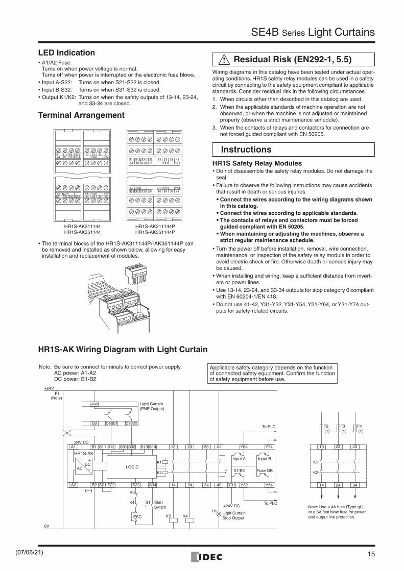
HR1S-AK Wiring Diagram with Light Curtain
LED Indication• A1/A2 Fuse:
Turns on when power voltage is normal.Turns off when power is interrupted or the electronic fuse blows.
• Input A-S22: Turns on when S21-S22 is closed.• Input B-S32: Turns on when S31-S32 is closed.• Output K1/K2: Turns on when the safety outputs of 13-14, 23-24,
and 33-34 are closed.
Terminal Arrangement
Wiring diagrams in this catalog have been tested under actual oper-ating conditions. HR1S safety relay modules can be used in a safety circuit by connecting to the safety equipment compliant to applicable standards. Consider residual risk in the following circumstances.1. When circuits other than described in this catalog are used.2. When the applicable standards of machine operation are not
observed, or when the machine is not adjusted or maintained properly (observe a strict maintenance schedule).
3. When the contacts of relays and contactors for connection are not forced guided compliant with EN 50205.
HR1S Safety Relay Modules• Do not disassemble the safety relay modules. Do not damage the
seal.• Failure to observe the following instructions may cause accidents
that result in death or serious injuries.•••• Connect the wires according to the wiring diagrams shown
in this catalog.•••• Connect the wires according to applicable standards.•••• The contacts of relays and contactors must be forced
guided compliant with EN 50205.•••• When maintaining or adjusting the machines, observe a
strict regular maintenance schedule.
• Turn the power off before installation, removal, wire connection, maintenance, or inspection of the safety relay module in order to avoid electric shock or fire. Otherwise death or serious injury may be caused.
• When installing and wiring, keep a sufficient distance from invert-ers or power lines.
• Use 13-14, 23-24, and 33-34 outputs for stop category 0 compliant with EN 60204-1/EN 418.
• Do not use 41-42, Y31-Y32, Y31-Y54, Y31-Y64, or Y31-Y74 out-puts for safety-related circuits.
HR1S-AK311144HR1S-AK351144
HR1S-AK311144PHR1S-AK351144P
13Y6423 33
Y7441
14Y31
24Y32
34 42Y54
A1S11
B1S12
S13S31
S14S32
S21A2
S22 S33 S34B2/
S11A1
S12B1
S31S13
S32S14
A2S21 S22 S33 S34
13 23Y64
33 41Y74
Y3114
Y3224 34
Y5442
B2/
• The terminal blocks of the HR1S-AK311144P/-AK351144P can be removed and installed as shown below, allowing for easy installation and replacement of modules.
Residual Risk (EN292-1, 5.5)
Instructions
ESC
A1 B1 S11 S12 S31 S32 S13 S14 13 23 33 41 Y64 Y74
A2
ACDC
S21 S22 S33 S34 14 24 34 42 Y31 Y32 Y54B2
Input A Input B
K1/K2 Fuse OK
+24V DC
K3 K4H1
S1
K3
K4
LOGIC
+
–
(–)
HR1S-AK
K1
K2
24V DC
0V
+24VF1
0V OSSD1 OSSD2
+24V
(Note)
K1
K2
13 23 33
14 24 34
F2 F3 F4(1) (1) (1)
Light Curtain(PNP Output)
StartSwitch
Light CurtainStop Output
To PLC
To PLCNote: Use a 4A fuse (Type gL) or a 6A fast blow fuse for power and output line protection.
Applicable safety category depends on the functionof connected safety equipment. Confirm the function of safety equipment before use.
Note: Be sure to connect terminals to correct power supply.AC power: A1-A2DC power: B1-B2
(07/06/21)
IDEC CORPORATION (USA)1175 Elko Drive, Sunnyvale, CA 94089-2209, USATel: +1-408-747-0550 / (800) 262-IDEC (4332) Fax: +1-408-744-9055 / (800) 635-6246E-mail: [email protected]
IDEC CANADA LIMITEDUnit 22-151, Brunel Road, Mississauga, Ontario, L4Z 1X3, CanadaTel: +1-905-890-8561, Toll Free: (888) 317-4332 Fax: +1-905-890-8562E-mail: [email protected]
IDEC AUSTRALIA PTY. LTD.2/3 Macro Court, Rowville, Victoria 3178, AustraliaTel: +61-3-9763-3244, Toll Free: 1800-68-4332Fax: +61-3-9763-3255E-mail: [email protected]
IDEC ELECTRONICS LIMITEDUnit 2, Beechwood, Chineham Business Park, Basingstoke, Hampshire RG24 8WA, UKTel: +44-1256-321000, Fax: +44-1256-327755E-mail: [email protected]
7-31, Nishi-Miyahara 1-Chome, Yodogawa-ku, Osaka 532-8550, JapanTel: +81-6-6398-2571, Fax: +81-6-6392-9731E-mail: [email protected]
Specifications and other descriptions are subject to change without notice.
Cat. No. EP1131-0 JULY 2006 14.2DNP PRINTED IN JAPAN
IDEC ELEKTROTECHNIK GmbHWendenstrasse 331, 20537 Hamburg, GermanyTel: +49-40-25 30 54 - 0, Fax: +49-40-25 30 54 - 24E-mail: [email protected]
IDEC (SHANGHAI) CORPORATIONRoom 608-609, 6F, Gangtai Plaza, No. 700, Yan'an East Road, Shanghai 200001, PRCTel: +86-21-5353-1000, Fax: +86-21-5353-1263E-mail: [email protected]
IDEC (BEIJING) CORPORATIONRoom 211B, Tower B, The Grand Pacific Building, 8A Guanghua Road, Chaoyang District, Beijing 100026, PRCTel: +86-10-6581-6131, Fax: +86-10-6581-5119
IDEC (SHENZHEN) CORPORATIONUnit AB-3B2, Tian Xiang Building, Tian’an Cyber Park, Fu Tian District, Shenzhen, Guang Dong 518040, PRCTel: +86-755-8356-2977, Fax: +86-755-8356-2944
IDEC IZUMI (H.K.) CO., LTD.Unit 1505-07, DCH Commercial Centre No. 25, Westlands Road, Quarry Bay, Hong KongTel: +852-2803-8989, Fax: +852-2565-0171E-mail: [email protected]
IDEC TAIWAN CORPORATION8F-1, No. 79, Hsin Tai Wu Road, Sec. 1, Hsi-Chih, Taipei County, Taiwan Tel: +886-2-2698-3929, Fax: +886-2-2698-3931E-mail: [email protected]
IDEC IZUMI ASIA PTE. LTD.No. 31, Tannery Lane #05-01,HB Centre 2, Singapore 347788Tel: +65-6746-1155, Fax: +65-6844-5995E-mail: [email protected]
www.idec.com
(07/06/21)