leica s series user manual s9 e/user...s series user manual 3 important safety notes user manual...
TRANSCRIPT

Leica S SeriesUser Manual

S Series User Manual 2
General Instructions
Safety conceptBefore using your stereo microscope for the first time, please read the "Safety Concept" booklet included with your instrument. It contains additional information about handling and care.
About cleaning O Do not use any unsuitable cleaning agents,
chemicals or techniques for cleaning.
O Never use chemicals to clean colored surfaces or accessories with rubberized parts. This could damage the surfaces, and specimens could be contaminated by abraded particles.
Servicing O Repairs may only be carried out by Leica
Microsystems-trained service technicians. Only original Leica Microsystems spare parts may be used.
Responsibilities of person in charge of instrument
O Ensure that the Leica stereo microscope is operated, maintained and repaired by authorized and trained personnel only.

S Series User Manual 3
Important Safety Notes
User manualUser manuals and updates are available for you to download and print from our website www.leica-microsystems.com. Keep it in a safe place, and readily accessible to the user.
This user manual describes the special functions of the Leica stereo microscopes (S series) and contains important instructions for their operational safety, maintenance, and accessories.
The "Safety Concept" booklet contains additional safety information regarding the service work, requirements and the handling of the stereo microscope, accessories and electrical accessories as well as general safety instructions.
You can combine individual system articles with articles from external suppliers (e.g. cold light sources, etc.). Please read the user manual and the safety requirements of the supplier.
Before installing, operating or using the instruments, read the user manuals listed above. In particular, please observe all safety instructions.
To maintain the unit in its original condition and to ensure safe operation, the user must follow the instructions and warnings contained in these user manuals.

S Series User Manual 4
Symbols Used
Warning of a danger
This symbol indicates especially important information that is mandatory
to read and observe.
Failure to comply can cause the following: O Hazards to personnel
O Functional disturbances or damaged instruments
Warning of hazardous electrical voltage
This symbol indicates especially important information that is
mandatory to read and observe.
Failure to comply can cause the following: O Hazards to personnel
O Functional disturbances or damaged instruments
Danger due to hot surface
This symbol warns against touching hot surfaces, e.g. those of light bulbs.
Important information
This symbol indicates additional information or explanations that intend
to provide clarity.
Explanatory notes O This symbol within the text stands for
additional information and explanations.
Figures(1) Numbers in parentheses within the
descriptions relate to the figures and the items within those figures.

S Series User Manual 5
Safety Instructions
DescriptionThe individual modules fulfill the highest requirements for observation and documentation of Leica stereo microscopes of the S series.
Intended use O Refer to "Safety Concept" booklet
Non-intended use O Refer to "Safety Concept" booklet
Never use S series microscopes or their components for surgical procedures (e.g. on the eye) unless they are specifically intended for that purpose.
The devices and accessories described in this User Manual have been tested with regard to potential hazards. The responsible Leica affiliate must be consulted whenever the instrument is altered, modified or used in conjunction with non-Leica components that are outside of the scope of this manual!
Unauthorized alterations to the instrument or noncompliant use shall void all rights to any warranty claims!
Place of use O Refer to "Safety Concept" booklet
O Electrical components must be placed at least 10 cm away from the wall and from flammable substances.
O Avoid large temperature fluctuations, direct sunlight and vibrations. These conditions can distort measurements * and micrographic images.
O In warm and warm-damp climatic zones, the individual components require special care in order to prevent the build-up of fungus.
* Measurement results depend on used objective, zoom and microscope settings.
Responsibilities of person in charge of instrument
O Refer to "Safety Concept" booklet
Ensure that: O The S series stereo microscopes and
accessories are operated, maintained and repaired by authorized and trained personnel only.
O All operators have read, understood and observe this User Manual, and particularly the safety instructions.

S Series User Manual 6
Safety Instructions (Continued)
Repairs, service work O Refer to "Safety Concept" booklet
O Only original Leica Microsystems spare parts may be used.
O Before opening the instruments, switch off the power and unplug the power cable.
Touching the live circuit can cause injury.
Transport O Use the original packaging for shipping
or transporting the individual modules of the Leica S stereo microscopes and the accessory components.
O In order to prevent damage from vibrations, all moving parts that (according to the user manual) can be assembled and disassembled by the customer should be disassembled and packed separately.
Integration in third-party products O Refer to "Safety Concept" booklet
Disposal O Refer to "Safety Concept" booklet
Legal regulations O Refer to "Safety Concept" booklet
EC Declaration of Conformity O Refer to "Safety Concept" booklet

S Series User Manual 7
Safety Instructions (Continued)
Health risks
• Workplaces with stereo microscopes facilitate and improve the viewing task,
but they also impose high demands on the eyes and holding muscles of the user. Depending on the duration of uninterrupted work, asthenopia and musculoskeletal problems may occur. For this reason, appropriate measures for reduction of the workload must be taken:
O Optimal arrangement of workplace, work assignments and work flow (changing tasks frequently).
O Thorough training of the personnel, giving consideration to ergonomic and organizational aspects.
O The ergonomic optical design and construction of the Leica S stereo microscopes are intended to reduce the exertion of the user to a minimum.
• Direct contact with eyepieces is a potential transmission method for
bacterial and viral infections of the eye.
The risk can be kept to a minimum by using personal eyepieces for each individual or detachable eyecups.

S Series User Manual 8
General Instructions 2Important Safety Notes 3Symbols Used 4Safety Instructions 5Contents 8
Leica S SeriesCongratulations! 11The Modular Design: Everything is Possible 12What Your Stereo Microscope has to Offer you 13Microscopes of the S Series 14On We Go 15
AssemblyInstalling the Basic Equipment (Overview) 17Focusing Column 18Sub-base for Transmitted Light and Cold Light Source 19Optics Carrier and Additional Objective 20Available Graticules 21Inserting Graticules 22Eyepieces 23Leica LED Illumination 24Camera Design (Leica S9 D and S APO) 25
Quick Start GuideAn Overview of a S Series Stereo Microscope 27Using the Eyepieces 28The Correct Interpupillary Distance 29Focusing 30Changing Magnification (Zooming) 31Limiting Zoom Range 32Regulating the Resistance of the Focusing Drive 34Changing the Position of the Optics Carrier 35Diopter Settings and Parfocality: 1 Adjustable & 1 Fixed Eyepiece 36Dioptric Correction With two Adjustable Eyepieces 39Connectivity of the S9 i Stereo Microscope With Integrated Camera 42The S9 i With Integrated Camera 43S9 i: Overview 44
Get Set!USB Mode – Capturing and Adjusting Images Using a Computer 46HDMI Mode – Capturing Images Without a Computer or Without a Wireless Device 48Adjusting Settings While in SD Mode 50Ethernet Mode – Capturing and Adjusting Images Using a Network 51
Contents

S Series User Manual 9
Extend!How to Install the Coded Zoom 53Installation of the Coded Zoom in LAS X 55
The Camera Remote Control Optional Remote Control 58Viewing Images and Movies With the Optional Remote Control 59Calling up the Camera Menu 60COLOR (Automatic White Balance) 61COLOR (Manual White Balance) 62EXPOSURE 63RESOLUTION 64SETUP CAMERA (Camera Settings) 65SETUP USER 66SETUP ETHERNET 67Pairing Cameras With Remotes 69
Photography & VideoPhotography & Video 71Photography With the Leica S9 D and S APO 72
Dimensional Drawings in mmLeica S9 E With Incident Light and Transmitted Light Illumination 74Leica S9 D With Incident Light and Transmitted Light Illumination 75Leica S9 i With Incident Light and Transmitted Light Illumination 76Leica S APO With Incident Light and Transmitted Light Illumination 77
Technical DataTechnical Data 79
AppendixCalculating the Total Magnification/Field of View Diameter 81Troubleshooting 82Care, Maintenance, Contact Persons 83
Contents

S Series User Manual Leica S Series 10
Leica S Series

S Series User Manual Leica S Series 11
Congratulations!
Congratulations on obtaining your new Leica stereo microscope from the S series. We are convinced it will exceed your expectations, as this instrument embodies all the qualities you associate with Leica Microsystems: excellent objectives, high-quality engineering, and reliability. Furthermore, the modular design ensures that the Leica stereo microscope adapts perfectly to your needs – no matter which accessories you require for your tasks.
Thanks to the parfocal system with simultaneously large working distances and object fields, you can always view your microscopic specimens accurately – from the complete image to the finest detail.
Though the reliability and robustness of Leica stereo microscopes is world-renowned, like any high-tech product, the Leica S series requires a certain degree of care and attention. Therefore, we recommend that you read this manual. It contains all the information you need regarding operation, safety and maintenance. Simply observing a few guidelines will ensure that even after years of intensive use, your stereo microscope will continue to work as smoothly and reliably as on the very first day.
We wish you the best of success in your work! after all, you are now equipped with the best tool!

S Series User Manual Leica S Series 12
Have a special request? Let us know!Leica Microsystems enjoys an exceptional reputation when it comes to devising customer-specific solutions. If you have a special request that cannot be met with standard parts, contact your Leica consultant. They have a solution for every application.
The Modular Design: Everything is Possible
The Leica S series provides a high degree of flexibility in choosing equipment, thanks primarily to the modular configuration and the compatibility that Leica has painstakingly maintained for decades. The optics carriers, eyepieces, stands, and more can be combined in any way you choose, allowing you to create the stereo microscope that best suits your needs.
Despite this, you will notice that the controls and individual components do not differ significantly. Whichever configuration you choose, you will quickly feel right at home with your new stereo microscope.

S Series User Manual Leica S Series 13
What Your Stereo Microscope has to Offer you
The optical system of the S series stereo microscopes consists of two beam paths converging at 10°. The objective pairs of each optical path are positioned close together, so the stereo microscopes can be of very "slender" design, especially towards the base of the instrument. The advantage: The advantages of this design are that it has a small space requirement for use on bonders and in machine applications, unobstructed access to specimens, plenty of space for tools and a completely clear view of the object field.
The Greenough system enables cost-effective correction of aberrations such as chromasia, image field curvature, and distortion with minimal effort. In all S series microscopes the optimum corrected center of the objective ensures high image quality. This provides superior optical performance with large, level and undistorted fields of view and chromatically optimized, high-contrast images.
Patented FusionOptics TechnologyThe S9 E, S9 D, S9 i feature the Leica patented FusionOptics technology and deliver you finest details in 3D. While the right channel delivers you a high-resolution image at the largest possible numerical aperture, the left channel presents an image with high depth of field. This results in an image perception with outstanding richness of details and exeptional depth of field at the same time.
PhotographyThe S9 D and S APO are equipped with an integrated video/phototube, which allows the simple, fast mounting of digital cameras. The S9 i with integrated camera has an SD card slot and allows image sharing via Ethernet connection.
Apochromatic correction The Leica S Series is a completely apochromatically corrected Greenough system. The modern optical technology of the Leica S Series corrects chromatic aberration perfectly, removes bothersome color seams and displays pin-sharp images of even the finest enlarged detail. Contrast, brilliance, image sharpness, resolution, color fidelity and image precision are unsurpassed. The benefit of apochromatic correction is best seen in specimens that have a fine, low-contrast structure such as large animal cells, cilia plants or metallic microelectronic structures.
The technical features of the individual models can be found on page 79.

S Series User Manual Leica S Series 14
Microscopes of the S Series
Leica S9 E Leica S9 D
Leica S9 i Leica S APO

S Series User Manual Leica S Series 15
On We Go
If your new stereo microscope has already been assembled and commissioned by your Leica consultant, click here to skip through the installation instructions and go directly to the Quick Start Guide on page 26.
If, on the other hand, you are assembling the stereo microscope yourself, continue with the "Assembly" chapter, which begins on page 16.

S Series User Manual Assembly 16
Assembly

S Series User Manual Assembly 17
Installing the Basic Equipment (Overview)
1. Sub-base for transmitted light with glass stage plate
2. Incident light base with stage plate
3. Focusing column with microscope carrier
4. Additional objective, optional
5. Optics carrier
6. Eyepieces, fixed and/or adjustable
6
5
4
3
2
1

S Series User Manual Assembly 18
• Never unscrew the 3 screws on the right side of the focusing column.
Focusing Column
Focusing column on the incident light base1. Remove the stage plate.
2. Route the 3 hollow screws from below through the base plate and screw these securely into the focusing column.
3. Insert the stage plate back into place.

S Series User Manual Assembly 19
1. Remove the glass stage plate.
2. Pull the locking mechanism forward.
3. Set the incident-light stand to the sub-base for transmitted light and engage it with the connection screw.
4. Press the locking mechanism backward. The incident light base and the sub-base for transmitted light are now connected.
5. Insert the glass stage plate.
6. Insert the universal light guide in the opening at the rear.
Additional information can be found in the user manual for cold-light source
Leica KL300 LED.
Sub-base for Transmitted Light and Cold Light Source

S Series User Manual Assembly 20
Optics carrier1. Insert the optics carrier carefully in the
microscope carrier and fasten it in the desired position with the clamping screw.
Additional objective (optional)1. Screw the desired objective counter
clockwise into the optics carrier.
Protective objective glass (optional)1. Screw the objective protective glass
directly onto the objective.
Optics Carrier and Additional Objective

S Series User Manual Assembly 21
The optional graticules enable measurement and, in addition, provide
valuable information when comparing and capturing still images of the specimens. Insert the graticule before you set the eyepiece in place.
Available GraticulesThe following graticules and objective micrometers for calibrating may be ordered:
O Graticule 10 mm/0.1 mm O Graticule 5 mm/0.1 mm O Graticule 5 mm/0.05 mm O Graticule 100 Div./0.002" O Graticule 100 Div./0.001" O Graticule 150 Div./0.0005" O Crosshairs O Stage micrometer 50 mm, 0.1/0.01/ mm
graduation O Stage micrometer 1", 0.001" graduation
Available Graticules

S Series User Manual Assembly 22
Graticules can be inserted in the adjustable eyepieces and the in the
eyepieces for eyeglass wearers.
The procedure for taking measurements is described in the "Measuring" user
manual.
Inserting graticule(s)1. Use the stereo microscope to determine
the side on which the scale is inscribed. The scale must not appear reversed.
2. Remove the insert from the bottom of the eyepiece and place it on the bench with the knurled side down.
3. Hold the graticule by the edges to avoid leaving fingerprints, and push it into the holder from the side.
4. Replace the insert in the eyepiece and press it firmly into place.
5. Insert the eyepiece in the tube and turn the eyepiece in the tube to align the graticule correctly.
Inserting Graticules

S Series User Manual Assembly 23
You can use your S series stereo microscope together with a fixed or
adjustable eyepiece. For models in which a graticule is included in an eyepiece for measurement or photography, two eyepieces are necessary. We recommend that you also equip the high-powered S APO with two adjustable eyepieces.
Inserting the eyepieces1. Push eyepieces as far as they will go into
the tubes.
2. Check that the eyepieces are seated firmly and precisely in place.
Risk of infection
Direct contact with eyepieces is a potential transmission method for
bacterial and viral infections of the eye. The risk can be kept to a minimum by using personal eyepieces for each individual or detachable eyecups.
Eyepieces

S Series User Manual Assembly 24
The Leica KL300 LED cold light source with its fiber-optic light guides is ideally
suited for the Leica S9 series stereo microscopes. A number of matching adapters are available for connecting the Leica KL300 LED cold light source to various stereo microscope stands and for stand-alone operation.
For detailed information about installation and use, please refer to the user manual for the Leica KL300 LED.
Please note that the universal light guide on the Leica S APO can only be used with
the light arm mounted on the side.
High-output illuminators
• For higher demands, such as photography or in use combination
with the Leica S APO, we offer different high-performance transmitted light stands and LED incident light illumination, as in the Leica LED3000 series, for example. Please ask your Leica consultant about the options.
Leica LED Illumination

S Series User Manual Assembly 25
The Leica S9 D and S APO are equipped with an integrated video/phototube,
which allows the simple, fast mounting of digital cameras for photos and video. Please ask your Leica consultant about the options.
Detailed information about the available camera systems, accessories and the
software packages from Leica can be found in the corresponding manuals.
Installing the camera1. Remove the protective dust cover from the
video/projection lens (c-mount adapter) and the microscope camera.
2. Screw the camera into the video/projection lens (c-mount).
3. Insert the unit into the video/photo output of the stereo microscope and screw it in.
• Always close the video/photo output with the protective dust cover if no
camera is installed.
Camera Design (Leica S9 D and S APO)

S Series User Manual Quick Start Guide 26
Quick Start Guide

S Series User Manual Quick Start Guide 27
1. Magnification changer, right drive knob with magnification scale
2. Focusing drive
3. Fixing screw for optics carrier in the microscope carrier
4. Adjustable tube: Interpupillary distance adjustable from 50 to 76 mm
5. Eyepieces
6. Threads for fastening the light arm (both sides and rear)
7. Illumination Leica LED3000 SLI
8. Illumination Leica LED3000 RL
9. Leica microscope camera
10. C-mount adapter and video/photo tube
An Overview of a S Series Stereo Microscope
1
6
7
9
4
5
3
2
10
8

S Series User Manual Quick Start Guide 28
Using the Eyepieces
The eyepieces form the connection between the tube and the eye of the
observer. Simply push them into the tube and they are ready to use.
What does "parfocal" mean?
"Parfocal" means that a specimen continues to remain exactly in focus, even
if the magnification on the stereo microscope is modified. All stereo microscopes from Leica Microsystems are parfocally matched. However, the parfocality requires a personal dioptric correction for the user.
Dioptric correctionIn order to parfocally match the stereo microscope, at least one eyepiece with dioptric correction is necessary. The setup is described on the following pages:
O With one adjustable and one fixed eyepiece: from page 36.
O With two adjustable eyepieces: from page 39.
If you do not wear glasses:Depending on the preferences of the observer, eyecups can be used.
To avoid eye infections, we recommend that every user uses his or her own pair
of eyecups.
If you wear glasses:
Eyeglass wearers must remove or fold back the eyecups (Fig. below left), as
otherwise they cannot see the entire field of view.

S Series User Manual Quick Start Guide 29
The Correct Interpupillary Distance
The interpupillary distance is correctly set if you see a single circular image field
when looking at a specimen.
If you are still a novice microscope user, you may need a short time to become accustomed to this. Not to worry – after a little while, it will become automatic.
Reference valueThe interpupillary distance can be set between 50 and 76 mm.
An "exit pupil distance" is the distance between eye and eyepiece. With the
10×/23B wide-field eyepiece for eyeglass wearers, it is approx. 22 mm. For those who do not use the eyepiece for eyeglass wearers, it is 12 mm.
Setting the eye distance1. Bring the eyes slowly to the eyepieces.
2. Push the tubes together or apart with both hands until you see a single round, circular image field without shadows with both eyes.

S Series User Manual Quick Start Guide 30
Focusing raises and lowers the stereo microscope using the focusing drive. The
specimen detail is brought into sharp focus as soon as it is in the focal point of the objective.
The focusing drive can be operated either left- or right-handed.
Focusing1. Align the specimen under the objective.
2. Set the lowest magnification level.
At the lowest magnification, the desired specimen detail can be easier to localize
due to the large field of view.
3. Look into the eyepieces and insert the desired specimen detail in the center.
4. Focus on the specimen with the drive knob.
Focusing

S Series User Manual Quick Start Guide 31
Changing Magnification (Zooming)
All stereo microscopes of the S series allow a continuous magnification change.
The magnification changer can be operated with the left and the right hand. The image scale is shown on the right drive knob.
The basis for the calculation of the total magnification and the field of view can
be found on page 81.
Changing magnification1. Look into the eyepieces.
2. Focus on the object (see page 30).
3. Rotate the magnification changer until the desired magnification is configured.

S Series User Manual Quick Start Guide 32
Limiting Zoom Range
With the S APO, the zoom range can be limited at the top and bottom. In the same manner, a fixed magnification level can be set. The following example shows the limit to the range between 1 to 3.2.
Defining the lower limit1. Loosen the hollow screw on the left drive
knob with the Allen key provided.
2. Turn the right drive knob to position "1".
3. Set the stop on the left drive knob forward until it touches the built-in zoom stop.
4. Carefully tighten the Allen screw.
Continued on next page

S Series User Manual Quick Start Guide 33
3. Set the stop backward on the right drive knob until it touches the built-in zoom stop.
4. Carefully tighten the Allen screw.
Defining the upper limit stop1. Loosen the hollow screw on the right drive
knob with the Allen key provided.
2. Turn the right drive knob to position "3.2".
Limiting Zoom Range (Continued)

S Series User Manual Quick Start Guide 34
Adjusting the resistanceIs the focusing drive too loose or too tight? Does the equipment tend to slide downwards? The resistance can be adjusted individually depending on the equipment weight and personal preferences as follows:
1. Grip the outer drive knobs with both hands and turn them towards each other until the desired resistance is reached during focusing.
Regulating the Resistance of the Focusing Drive

S Series User Manual Quick Start Guide 35
The optics carrier can be turned sideways in the microscope carrier if the user
wants to work from the side.
Changing position1. Unscrew the clamping screw.
2. Turn the optics carrier laterally to the desired position.
3. Carefully tighten the clamping screw.
Changing the Position of the Optics Carrier

S Series User Manual Quick Start Guide 36
If you set the diopters on the adjustable eyepiece exactly as described, the
image will remain equally sharp and constant (parfocal) from the lowest to the highest magnification. This means you do not have to refocus when changing magnification. The focus needs to be readjusted only if you want to view a specimen detail that is located higher or lower. Use this advantage as often as possible, it is not available on all stereo microscopes.
The diopters can be set between +5 and -5.
The following adjustments have to be carried out only once by each user. Using
reticules leads to slightly deviated settings, which are described in the user manuals on the reticules (measurement).
Adjusting the diopter settings1. With Leica S APO, turn the rotary knob to
the "Vis" setting.
2. Turn the dioptric correction on the adjustable eyepiece to the center position.
Continued on next page
Diopter Settings and Parfocality: 1 Adjustable & 1 Fixed Eyepiece

S Series User Manual Quick Start Guide 37
Diopter Settings and Parfocality: 1 Adjustable & 1 Fixed Eyepiece (Continued)
9. Turn the eyelens of the eyepiece as far as it will go in the "+" direction, without looking into the eyepieces while doing so.
10. Close your eye on the fixed eyepiece and look with the other eye into the into the adjustable eyepiece.
11. Rotate the eyelens of the eyepiece slowly in the "–" direction until the eye can see the specimen sharply.
Continued on next page
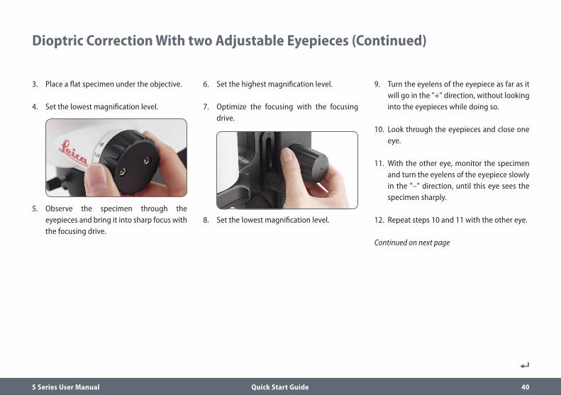
6. Set the highest magnification level.
7. Optimize the focusing with the focusing drive.
8. Set the lowest magnification level.
3. Place a flat specimen under the objective.
4. Set the lowest magnification level.
5. Observe the specimen through the eyepieces and bring it into sharp focus with the focusing drive.

S Series User Manual Quick Start Guide 38
Diopter Settings and Parfocality: 1 Adjustable & 1 Fixed Eyepiece (Continued)
Checking parfocality1. Select the highest magnification level.
2. Monitor the specimen; if necessary, refocus it slightly.
3. Change from the highest to the lowest magnification. The sharpness should be constant (parfocal). If this is not the case, repeat this procedure.

S Series User Manual Quick Start Guide 39
Dioptric Correction With two Adjustable Eyepieces
If you set the diopters on the adjustable eyepiece exactly as described, the
image will remain equally sharp and constant (parfocal) from the lowest to the highest magnification. This means you do not have to refocus when changing magnification. The focus needs to be readjusted only if you want to view a specimen detail that is located higher or lower. Use this advantage as often as possible, it is not available on all stereo microscopes.
The diopters can be set between +5 and -5.
The following adjustments have to be carried out only once by each user. Using
reticules leads to slightly deviated settings, which are described in the user manuals on the reticules (measurement).
Adjusting the diopter settings1. With Leica S APO, turn the rotary knob to
the "Vis" setting.
2. Turn the dioptric correction on both eyepieces to the center position.
Continued on next page
S Series User Manual Quick Start Guide 40
9. Turn the eyelens of the eyepiece as far as it will go in the "+" direction, without looking into the eyepieces while doing so.
10. Look through the eyepieces and close one eye.
11. With the other eye, monitor the specimen and turn the eyelens of the eyepiece slowly in the "–" direction, until this eye sees the specimen sharply.
12. Repeat steps 10 and 11 with the other eye.
Continued on next page
6. Set the highest magnification level.
7. Optimize the focusing with the focusing drive.
8. Set the lowest magnification level.
3. Place a flat specimen under the objective.
4. Set the lowest magnification level.
5. Observe the specimen through the eyepieces and bring it into sharp focus with the focusing drive.
Dioptric Correction With two Adjustable Eyepieces (Continued)

S Series User Manual Quick Start Guide 41
Checking parfocality1. Select the highest magnification level.
2. Monitor the specimen; if necessary, refocus it slightly.
3. Change from the highest to the lowest magnification. The sharpness should be constant (parfocal). If this is not the case, repeat this procedure.
Dioptric Correction With two Adjustable Eyepieces (Continued)

S Series User Manual Quick Start Guide 42
The S9 i features an integrated, and networkcapable state of the art brightfield camera with 10 megapixel image resolution. There are various ways to connect the S9 i with your viewing devices:
Connectivity of the S9 i Stereo Microscope With Integrated Camera
Use Ethernet mode to connect the S9 i with your facilities' network via Ethernet (RJ45) cable.
For PC use the Leica Application Suite (LAS) Software (LAS 4.9 / LAS X 3.0 or higher) and for MAC use Leica Aquire (version 3.3 or higher) to capture images. For mobile devices check the Apple App Store or Google Play for the Leica AirLab App from Leica Microsystems.
Use USB mode to connect the S9 i directly via USB cable with a PC or MAC.
Use HDMI mode to connect the S9 i to a large HD-screen for a standalone solution without computer. You can save images directly onto SD card when operating in this mode.
Capture images from any remote PC or MAC with access
to your network (LAN).
Even mobile devices can be used if there is a WLAN-connection to the same
network.
Ethernet mode USB mode HDMI mode

S Series User Manual Quick Start Guide 43
The integrated HD camera has many possibilities for various applications
and conditions of use. Below are some basic concepts to help you get the most performance for your application.
In order to keep your camera up to date and to benefit from newest functions you
should update the camera's firmware from time to time. Detailed instructions about this topic can be found in the download section of the S9 i on our website. To check out your camera's firmware version use the information box in stand-alone mode (see section remote control) or the "About" section in the software on the computer.
Power S9 iPower can be provided to the camera in the following ways:
O USB power connector on the microscope stand
O External USB power supply
O USB connectors on the PC
1. Capture button O Used to capture an image in HDMI mode
2. Mode switch O Switch into different modes (USB mode,
Ethernet mode, HDMI mode)
3. Mode panel O The mode panel with the symbols for USB,
Ethernet and HDMI (from top to bottom) indicates in which mode you are.
O The LEDs will flash when you change from one mode to another.
The S9 i With Integrated Camera
Note direct connection to an HD display is possible in all modes.
32
1

S Series User Manual Quick Start Guide 44
S9 i: Overview
1. LED status indicator
O Flashing when camera is starting
O Constant green means ready
2. Capture button for SD card capture
3. Mode switch to switch into different modes
4. Mode panel with symbols for USB, Ethernet, and HDMI (from top to bottom) indi cates the selected mode.
5. Socket for Ethernet cable
6. Socket for the HDMI cable
7. Socket for the USB cable
8. SD card slot
12
34 8
56
7

S Series User Manual Get Set! 45
Get Set!

S Series User Manual Get Set! 46
10× eyepieces have a fixed circular field of view of 18 mm or more diameter. The
field of view of the S9 i is rectangular to ensure an even field on the digital image. As a result, the image field of the camera is smaller than the object field seen through the eyepieces.
Installing and connecting1. Insert the provided CD into your computer,
and follow the instructions to load the software.
2. Insert the provided USB cable into the camera’s USB port, and attach the other end of the cable to a USB 2.0 port of your computer.
3. The status light blinks green. Wait until the status light stops flashing and one of the mode panel buttons turns green. This may take approximately 30 seconds.
USB Mode – Capturing and Adjusting Images Using a Computer
LAS
DVD

S Series User Manual Get Set! 47
4. If a mode other than USB is lit green, press the mode switch and wait until both the status LED and the USB mode panel stop flashing.
5. You are ready to launch the Leica software. Follow the software instructions to adjust and capture an image.
6. While in USB mode, you can connect the provided HDMI cable from the camera to an HD monitor or HD projector to share the image.
Note the image resolution on the HD projector or monitor is limited to the live
image resolution setting in the software. If an aspect ratio of 4:3 is choosen in the software, the image on the HDMI monitor will be distorted as shown below. This is due to the fact that the HDMI montior interprets every signal as having an 16:9 aspect ratio.
USB Mode – Capturing and Adjusting Images Using a Computer (Continued)
4:3 aspect ratio 4:3 aspect ratio image on a screen set to an aspect ratio of 16:9

S Series User Manual Get Set! 48
2. If a mode other than HDMI is lit green, press the mode switch and wait until both the status LED and the LED next to the HDMI mode panel stop flashing.
In order to use this mode, you need a SD card with enough free memory. If the
SD card is full, you will not be able to capture any images – a corresponding message will be shown.
Be sure the camera is connected to a power source.
1. The status light blinks green. Wait until the status light stopped flashing and one of the mode button's is also green. This may take approximately 30 seconds.
HDMI Mode – Capturing Images Without a Computer or Without a Wireless Device

S Series User Manual Get Set! 49
HDMI Mode – Capturing Images Without a Computer or Without a Wireless Device (Continued)
3. Insert the SD memory card into the slot on the side of the S9 i until the card clicks into place. The S9 i is now ready to capture images onto the SD memory card.
Capturing an image
• It is critical to properly set the microscope eyepieces’ diopters to
ensure that the images on the SD memory card are in focus when the image is in focus through the microscope’s eyepieces. Refer to the microscope’s user manual for proper diopter setting. Focus the microscope at high magnification, then change to the magnification at which you wish to capture the image. Do not refocus the microscope.
You can also use the HDMI output and an HD display (not provided) as a focusing aid.
4. To capture an image onto SD card, press the capture button, located on the side of the S9 i camera.
O You will hear a beep to acknowledge the button was pressed.
O The status LED flashes green while the image is being captured.
O You will hear another beep when the S9 i has completed capturing the image and the status LED will return to steady green.
The image is now saved on the SD card. Images which are on the SD card can be viewed using the optional remote control. See "Camera Remote Control" on page 57.
5. While in HDMI mode, you can connect the provided HDMI cable from the camera to an HD monitor or HD projector to share the image.

S Series User Manual Get Set! 50
Return to factory settingsPress and hold the pinhole switch for 5 seconds. Wait for the beep. The camera will now reset to factory settings.
Adjusting Settings While in SD Mode
Setting a new white balance
Make sure that there is no sample in the beam path and that a standard
illumination is available when you reset the camera.
Press and hold the capture button for 5 seconds. Wait for the beep. A new white balance is set.
It is recommended to set a new white balance each time you change the type
or color temperature of the illumination. This is especially needed when you work with halogen light which can be turned from low intensity yellow to a high intensity blue light. The new white balance setting will generate a neutral background for both illuminations.

S Series User Manual Get Set! 51
Ethernet Mode – Capturing and Adjusting Images Using a Network
1. Connect one end of an Ethernet cable to the camera and the other end of the cable to the Ethernet connection in your facility.
2. The status light blinks green. Wait until the status light stopped flashing and one of the mode buttons is also green. This may take approximately 30 seconds.
3. If a mode button other than Ethernet mode is lit green, then press the mode button and wait until both the status LED and the Ethernet LED mode button stopped flashing.
4. Follow the directions of your network compatible device to connect to your facilities network and select the camera.
5. Open the appropriate app on your mobile device or appropriate software on your PC for viewing, capturing, and adjusting the camera image (see page 43).

S Series User Manual Extend! 52
Extend!

S Series User Manual Extend! 53
How to Install the Coded Zoom
Scope of delivery Coded zoom knob kit for S9 stereo microscopes: Art. No.: 10 450 862
O one coded zoom knob (for the left zoom control)
O USB cable to connect the coded knob with a computer
These instructions describe the mounting of the coded zoom knob with a cabled
connection to a computer. Leica recommends to use the left side for mounting, as the right knob has the values for the zoom range imprinted. Most users will find it convenient to operate the zoom on the right side.
Dismount the normal zoom knob on the left1. Set the left zoom knob of the microscope to
the lowest magnification.
2. To install the coded knob you must dismount the old knob on the left side. For unscrewing use a 2.5 mm Allen key.
Mount the coded knob and connect it to a PC1. Check the inside of the coded knob to
assure the position of the screw on the lower, left side.
2. When you turn the knob you’ll see the screw through the hole.

S Series User Manual Extend! 54
4. Use the delivered USB cable to connect the coded zoom knob with your computer. The cable can be plugged into the zoom knob on the lower end.
How to Install the Coded Zoom (Continued)
3. Place the coded knob on the zoom knob opening and fix it with a 2.5 mm Allen key. Close the screw hole after mounting using the protective cap.
Do not change the position of the small black switch on the backside of the
coded knob.
After connecting the coded knob with your computer the operating system will
recognize the knob as an additional USB Device (“LEICA MAZ1”).

S Series User Manual Extend! 55
Installation of the Coded Zoom in LAS X
Installation of the coded zoom knob in the Leica Application Suite (LAS) Software X 1. Open the “Leica LAS X Hardware
Configurator”. Click on this link on your desktop.
2. Please select “Hardware Setup”.
3. Check the box to mark the “coded knob”. Calibration in LAS X (to lowest, highest, and 1× magnification)1. To calibrate the coded knob click on
“Configure” on the upper, left side. Then click on “Fine Tuning” in the right menu.
2. Manually set the zoom knob on the S9 to lowest magnification.
3. Confirm the setting to lowest limit in the software by clicking on “Go to lower Limit”.

S Series User Manual Extend! 56
Installation of the Coded Zoom in LAS X (Continued)
4. Repeat the procedure to calibrate the knob also for upper magnification (manually set the zoom to highest magnification on the microscope, then choose “Go to upper limit”).
5. Repeat the procedure again to calibrate the knob for 1.0× magnification (manually set the zoom to 1.0× magnification on the microscope, then choose “GO to nominal 1.0×”).
The coded zoom knob is now installed and calibrated for your S9 microscope
and you can close the hardware configurator tool.
Checking the functionality of the coded zoom knob in LAS X 1. Open the LAS X software to check if the
coded zoom now operates correctly.
2. Navigate to the Magnification Menu.
3. Go to the microscope and turn the zoom knob. The changing of the zoom should now be reflected in the Magnification Menu, and the zoom bar should move accordingly.
All functionalities in the LAS X software that correlate with magnification, e.g.
the scale bar or the measurement tool, use this automatically detected magnification value from the microscope for information.

S Series User Manual The Camera Remote Control 57
The Camera Remote Control
The remote control is designed to work only when the camera is in HDMI mode
and when the camera is used in combination with an HD display.
The only function which works in any mode is the "Info" function which shows details about the camera.

S Series User Manual The Camera Remote Control 58
The remote control only works in HDMI mode. Aside from the button. It will
display information about the camera on a HD display in every mode. The remote must be pointed at the IR receiver of the camera without obstructions.
1. Start/stop video recording
2. Save still image to SD card
3. Stop/continue live image, pause/play movie clip
4. View files on SD card
5. Move to previous image on SD card
6. Move to next image on SD card
7. Brightness adjustment up or down
8. Pairing button
9. Show/hide information box
10. White balance set button
11. Call up the camera menu
12. Arrow keys for navigation
13. OK to confirm
Optional Remote Control
1 3
5
2
46
7
8 9
10 11
12 13
7

S Series User Manual The Camera Remote Control 59
If you have purchased the optional remote, the Leica HD camera shows
images and movie clips directly on an HD monitor.
1. Thumbnail view (first press)
O up/down/left/right select thumbnail
O Show image in full screen or playback movie clip
O next image / previous image
O Play movie clip
O left /right fast forward / rewind
2. To return to live view press .
Viewing Images and Movies With the Optional Remote Control
Thumbnail view
Playback / fullscreen view

S Series User Manual The Camera Remote Control 60
The remote control can only work when the camera is in HDMI mode.
Opening and closing the camera menu1. Point the remote control towards the
camera.
2. Press the key on the remote control to show the camera menus on the monitor.
3. Press the and buttons to select a menu item.
4. Press the button to confirm a menu item.
5. Press the button again to hide the camera menus.
Calling up the Camera Menu

S Series User Manual The Camera Remote Control 61
Enabling automatic white balance1. Press the button on the remote control.
2. Call up the "COLOR" entry.
3. Set the value for "WB MODE" to "AUTO".
4. Press the button to exit the menu.
The values for "RED" and "BLUE" cannot be adjusted if the "WB MODE" setting is set to "AUTO".
COLOR
COLOR (Automatic White Balance)
EXPOSURE
RESOLUTION
SETUP CAMERA
SETUP USER
SETUP ETHERNET
SET WB
WB MODE
RED LEVEL
BLUE LEVEL
BLACK LEVEL
HUE
PRESS OK
AUTO
SATURATION
The "COLOR" function makes it possible to adapt the camera chip to the ambient light so that color-neutral images can be acquired.
Leica S9 i
46
41
0
1
12

S Series User Manual The Camera Remote Control 62
The "COLOR" function makes it possible to adapt the camera chip to the ambient light so that color-neutral images can be acquired.
Adjusting the white balance manually (recommended)1. Move the specimen out of the field of view so that only the illumination
is seen.
2. Press the button on the remote control.
3. Call up the "COLOR" entry.
4. Set the "WB MODE" to "MANUAL".
5. If necessary, correct the values for "RED" and "BLUE" until the image shows a uniform gray area.
6. Press the button to exit the menu.
COLOR (Manual White Balance)
COLOR
EXPOSURE
RESOLUTION
SETUP CAMERA
SETUP USER
SETUP ETHERNET
SET WB
WB MODE
RED LEVEL
BLUE LEVEL
BLACK LEVEL
HUE
PRESS OK
MANUAL
SATURATION
Leica S9 i
46
41
0
1
12

S Series User Manual The Camera Remote Control 63
Automatic exposure1. Press the button on the remote control.
2. Call up the command for automatic exposure (see diagram at the left).
3. Set the value for "EXP MODE" to "AUTO".
4. Correct the values for "BRIGHTNESS" and "GAMMA" until you obtain the desired results for the image.
Manual exposure1. Press the button on the remote control.
2. Call up the command for manual exposure (see diagram at the left).
3. Set the value for "EXP MODE" to "MANUAL".
4. Correct the values for "EXPOSURE (ms)", "GAIN" and "GAMMA" until you obtain the desired results for the image.
EXPOSURE
COLOR
EXPOSURE
RESOLUTION
SETUP CAMERA
SETUP USER
SETUP ETHERNET
EXP MODE
EXPOSURE (ms)
GAIN
BRIGHTNESS
GAMMA
AUTO
Leica S9 i
143
5
0
0.60
COLOR
EXPOSURE
RESOLUTION
SETUP CAMERA
SETUP USER
SETUP ETHERNET
EXP MODE
EXPOSURE (ms)
GAIN
BRIGHTNESS
GAMMA
MANUAL
Leica S9 i
143
5
0
0.60

S Series User Manual The Camera Remote Control 64
The "RESOLUTION" menu enables you to define the resolution for the live image, still image capture and video capture individually.
This provides optimum results in every situation.
LIVE (resolution of the live image)Defines the resolution of the live image.
CAPTURED (resolution of the captured image)Defines the resolution of the captured image on the SD card.
MOVIE (resolution of videos)Indicates the resolution of the captured videos on the SD card.
NETWORK STREAMDefines the resolution of the image transmitted over the Ethernet port.
RESOLUTION
COLOR
EXPOSURE
RESOLUTION
SETUP CAMERA
SETUP USER
SETUP ETHERNET
LIVE
CAPTURED
MOVIE
NET WORK STREAM
HD 1080i-50Hz
4k (16:9)
Leica S9 i
1080p (16:9)
720p (16-9)

S Series User Manual The Camera Remote Control 65
The camera settings enable you to control internal parameters such as the date or time, reset the camera, etc.
RESET CAMERAThis command resets the camera to the factory settings. All user information (such as white balance, resolution etc.) is reset.
SET DATE TIMEThis command sets the date and time as well as the format for displaying them. The following formats are available for selection: YYMMDD – DDMMYY – MMDDYY
FLIP IMAGESelect this to view your images horizontal, vertical, or horizontal and vertical.
AUDIO/BEEP You can decide to have a tone from the camera for some functions.
LANGUAGE Select the language of the On Screen Display.
SELECTING IMAGE OVERLAYS (SELECT OVERLAY)Press to select another overlay. Press to activate the selected overlay and leave the menu.
If you want to quickly display other overlays, press when the live image is displayed to show the next or previous respective
overlay.
The firmware of the camera can updated. For detailed instruction please consult the download section of this camera on the webpage
of Leica Microsystem.
GREYSCALEAllows you to remove the color information in the displayed and saved image.
SETUP CAMERA (Camera Settings)
COLOR
EXPOSURE
RESOLUTION
SETUP CAMERA
SETUP USER
SETUP ETHERNET
RESET CAM
SET DATE/TIME
FLIP IMAGE
AUDIO/BEEP
PRESS OK
PRESS OK
Leica S9 i
NONE
ENABLE
LANGUAGE
SELEC T OVERLAY
ENGLISH
NONE
GREYSCALE DISABLE

S Series User Manual The Camera Remote Control 66
The camera settings enable you to control internal parameters such as the date or time, reset the camera, etc.
HISTOGRAMEnables the display of a histogram as a picture in picture.
SHOW MENU Changes the display time of the menu bar. You can select between 10 seconds and infinity. The menu can still be deactivated if you press the camera menu button.
SETUP USER
COLOR
EXPOSURE
RESOLUTION
SETUP CAMERA
SETUP USER
SETUP ETHERNET
HISTOGRAM
SHOW MENU
DISABLE
10 SECONDS
Leica S9 i

S Series User Manual The Camera Remote Control 67
IP ADDRESSYou can choose if you want the IP address to be set automatically by your network (Dynamic) or you can manually enter an IP address using the onscreen keyboard (Static).
If you select "STATIC" for the IP address, you can select from the following options using the onscreen keyboard:
O IP address
O IP subnet mask
O Gateway IP address
This menu allows you to customize parameters relevant to working in Ethernet mode. Consult with your local IT expert for information
relating to your local network.
SETUP ETHERNET
COLOR
EXPOSURE
RESOLUTION
SETUP CAMERA
SETUP USER
SETUP ETHERNET
IP ADDRESS MODE
IP ADDRESS
IP SUBNET MASK
DHCP(Dynamic)
Leica S9 i
GATEWAY IP ADDRESS
COLOR
EXPOSURE
RESOLUTION
SETUP CAMERA
SETUP USER
SETUP ETHERNET
IP ADDRESS MODE
IP ADDRESS
IP SUBNET MASK
GATEWAY IP ADDRESS
STATIC
Leica S9 i
010.000.000.002
255.255.255.000
010.000.000.001

S Series User Manual The Camera Remote Control 68
SETUP ETHERNET (Continued)
Camera configuration1. Open camera configuration panel on your PC.
2. In the top right corner find the Ethernet setting section.
3. Find the dropdown menu labelled "IP ADDRESS MODE" and select "STATIC".
4. Enter the IP address in the relevant boxes ("IP ADDRESS", "IP SUBNET MASK", "GATEWAY IP ADDRESS").
5. Camera should be recognized.

S Series User Manual The Camera Remote Control 69
Pairing Cameras With Remotes
Pairing
The Leica S9 i and the remote control can be paired and then only respond to each
other. This can be helpful when using multiple cameras and remote controls.
1. Press the button to start or end the process.
In order to achieve successful pairing and avoid pairing by mistake, the second
step must be performed within 4 seconds.
If a "timeout" is displayed after 4 seconds, press the "Pair" button again to start the
process.
2. Press and hold the button on your remote control representing the channel that you want to assign to the connection (see image to the right, channel selection) until a corresponding confirmation is displayed on the HD monitor. All of the buttons except the button can be used for this.
3. The microscope only responds to the remote control commands from the remote control used for the pairing.
Resetting to factory setting1. Press the button to start the process.
2. Press the button until a corresponding confirmation is displayed on the HD monitor.

S Series User Manual Photography & Video 70
Photography & Video

S Series User Manual Photography & Video 71
For most stereo microscope users, digital documentation has become an invaluable part of their work. Research results can be presented in an appealing form, while measurements on the digital image provide clarity.
AdaptersIf camera control using the Leica Application Suite is not required, conventional mirror reflex and rangefinder cameras from third-party manufacturers can be used. Leica Microsystems offers various adapters for these.
Leica DFC and MC camerasIf you require absolute control over the camera and need the capability for measurement, evaluation and more in addition to photography, the digital Leica MC and DFC cameras are exactly right for you. Together with the Leica Application Suite, they provide virtually limitless freedom of use. For additional information about Leica cameras, refer to the camera's documentation.
Leica Application SuiteThe "Leica Application Suite", or "LAS" for short, is, as it were, the digital extension of your stereo microscope. With it, you can not only take images, but also control the illumination, the camera and more. For additional information, refer to the LAS online help.
Photography & Video

S Series User Manual Photography & Video 72
The observation beam path and the photobeam path can be switched at the
S APO. For this, the light splitting is influenced as follows:
O Position "Vis": 100 % light in both eyepieces, but no light in the video/photo beam path
O Position "Doc": 100 % light in the right eyepiece, but no light in the left eyepiece. 100 % of the light crosses the video/photo beam path
The focusing and the framing are done with the left eyepiece (video/photo
beam path).
Flat specimens are sometimes partially blurry on the left and right edge of the
image. This blurring is based on laws of optics and does not mean there is a malfunction of the camera or the microscope.
The S9 D has a built in 50:50 split of the beam path and allows observation through the eyepieces and digital imaging at the same time.
Capturing images and videos1. If the image detail and image sharpness are
set to your satisfaction, switch on the "Doc" setting and capture your image.
Photography With the Leica S9 D and S APO

S Series User Manual Dimensional Drawings in mm 73
Dimensional Drawings in mm

S Series User Manual Dimensional Drawings in mm 74
Leica S9 E With Incident Light and Transmitted Light Illumination
186
134
3511
8.5
379
22
278
205
148
205
107
278
ø58
ø76
52164
188
223
186
134
3511
8.5
379
2265
278
205
148
205220
107
278
ø58
ø76
52164
188
223

S Series User Manual Dimensional Drawings in mm 75
Leica S9 D With Incident Light and Transmitted Light Illumination
107
278
148
205
186
134
3511
8.5
379
22
ø58
ø76
208
223
278
205
52164
186
134
148
205220
35
52164
118.
5
379
2265
107
278
ø58
ø76
208
223
278
205

S Series User Manual Dimensional Drawings in mm 76
Leica S9 i With Incident Light and Transmitted Light Illumination
186
134
11063164
107
278
148
205
35
ø58
ø76
243
223
118.
5
379
22
278
205
186
134
11063164
107
278
148
205220
35
ø58
ø76
243
223
118.
5
379
2265
278
205
S Series User Manual Dimensional Drawings in mm 77
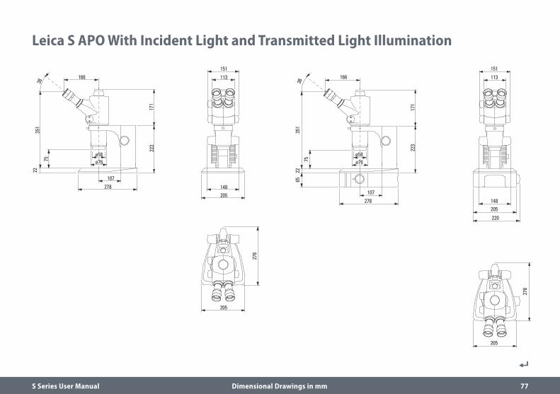
Leica S APO With Incident Light and Transmitted Light Illumination
166
107
75
351
3822
278
ø58ø76
151
113
148205
278
205
171
223
166
107
75
351
3822
65
223
278
ø58ø76
151
113
148205
220
278
205
171

S Series User Manual Technical Data 78
Technical Data

S Series User Manual Technical Data 79
Technical DataS9 E S9 D S9 i S APO
Optical system, lead-free10° Greenough using best-corrected central part of the objective
12° Greenough using best-corrected central part of the objective
Zoom 9:1 8:1, apochromatic
Viewing angle 35° 38°
Magnification range (basic outfit) 6.1× – 55× 10× – 80×
Maximum resolution 500 lp / mm 600 lp / mm
Maximum numerical aperture 0.167 0.2
Working distance (basic outfit) 122 mm 75 mm
Object field diameter 37.6 mm 23 mm
Adjustable zoom limits click-stops 10×, 20×, 30×, 40×, and 50× 2
Video/photo outlet – 50 % video 50 % visual, permanent
– 100 % visual or 100 % video/photo and 100 % visual in the left eyepiece
Integrated camera – – 10 MP resolution
Live image up to 35 fps (1,024 × 768 pixels)
Sensor size 6.44 mm × 4.6 mm, 1/2.3" CMOS
Pixel size 1.67 μm × 1.67 μm
Yes
Standard objectives, lead-free Apochromats 0.5×, 0.63×, 0.75×, 1.6×, 2.0× Apochromats 0.63×, 1.6×, 2.0×
Ergonomic eyepieces, fixed and adjustable, with cups
10× / 23, 16× / 16, 20× / 12–
Ergonomic eyepieces for eyeglass wearers, adjustable, with eyecups
10× / 23, 16× / 15, 25× / 9.5, 40×/ 6
Interpupillary distance 50 –76 mm

S Series User Manual Appendix 80
Appendix

S Series User Manual Appendix 81
Calculating the Total Magnification/Field of View Diameter
Parameter
MO Magnification of the additional objective
ME Magnification of eyepiece
z Magnification changer position
NFOV Field number of the eyepiece. Field numbers are printed on the eyepieces: 10×/23, 16×/16, 20×/12, 10×/23B, 16×14B, 25×/9.5B, 40×6B.
Example
MO Additional objective 1.6×
ME 20×/12 eyepiece
z Zoom position 4.0
Magnification in the binocular tube
MTOT VIS = MO × ME × z or
1.6 × 20 × 4 = 128
Calculation example: Field of view diameter in the specimen
∅ OF:NFOV
=12
= 1.9 mmMO × z 1.6 ×4

S Series User Manual Appendix 82
The field of view is shadowed O Adjusting the correct Interpupillary
Distance (page 29).
The image goes out of focus O Inserting the eyepieces correctly (page 28). O Perform diopter correction exactly
according to the instructions (from page 36).
The focusing drive gradually sinks on its own or is difficult to turn
O Regulate the ease of movement (page 30).
In the case of failures of electrically operated devices, always first check:
O Is the voltage selector set correctly? O Is the main power switch switched on? O Is the power cable connected correctly? O Are all connecting cables attached
correctly? O Are the fuses intact?
Photos are blurry O Focus accurately (page 30). O Bring the reticule into sharp focus and
perform diopter correction exactly according to the instructions (page 28).
O Insert the eyepieces correctly up to the stop (page 28).
O Check that the graticules are securely in place in the eyepiece (page 28).
The image from the camera stays black O Switch the beam splitter on the photo tube
to the "Doc" setting (page 72).
Troubleshooting

S Series User Manual Appendix 83
Care, Maintenance, Contact Persons
We hope you enjoy using your stereo microscope. Leica devices are renowned for their robustness and long service life. Observing the following care and cleaning tips will ensure that even after years and decades, your Leica stereo microscope will continue to work as well as it did on the very first day.
Warranty benefitsThe guarantee covers all faults in materials and manufacture. It does not, however, cover damage resulting from careless or improper handling.
Contact addressHowever, if your instrument should no longer function properly, contact your technician, your Leica representative or Leica Microsystems (Schweiz) AG, CH-9435 Heerbrugg.
E-mail contact:[email protected]
Care O Protect your stereo microscope from
moisture, fumes and acids and from alkaline, caustic and corrosive materials and keep chemicals away from the instruments.
O Plugs, optical systems and mechanical parts must not be disassembled or replaced, unless doing so is specifically permitted and described in this manual.
O Protect your stereo microscope from oil and grease.
O Do not grease guide surfaces or mechanical parts.

S Series User Manual Appendix 84
Care, Maintenance, Contact Persons (Continued)
Protection from dirtDust and dirt will affect the quality of your results.
O Put a dust cover over the stereo microscope when it will not be used for a long time.
O Use dust caps to protect tube openings, tubes without eyepieces, and eyepieces.
O Keep accessories in a dust-free place when not in use.
Cleaning polymer componentsSome components are made of polymer or are polymer-coated. They are, therefore, pleasant and convenient to handle. The use of unsuitable cleaning agents and techniques can damage polymers.
Permitted measures O Clean the stereo microscope (or parts of it)
using warm soapy water, then wipe using distilled water.
O For stubborn dirt, you can also use ethanol (industrial alcohol) or isopropanol. When doing so, follow the corresponding safety regulations.
O Remove dust with a pneumatic rubber bulb or with a soft brush.
O Clean objectives and eyepieces with special optic cleaning cloths and with pure alcohol.

10/2
019
· 10I
DS15
060E
N_2
· ©
201
9 by
Lei
ca M
icro
syst
ems
GmbH
.Su
bjec
t to
mod
ifica
tions
. LEI
CA a
nd th
e Le
ica
Logo
are
regi
ster
ed tr
adem
arks
of L
eica
Mic
rosy
stem
s IR
Gm
bH.
CONNECT
WITH US!
www.leica-microsystems.com
Leica Microsystems (Schweiz) AG · Max-Schmidheiny-Strasse 201 · 9435 Heerbrugg, Switzerland
T +41 71 726 34 34 · F +41 71 726 34 44