leica led3000 / leica led5000 user manual...leica led3000 / leica led5000 user manual 2 contents....
TRANSCRIPT
Leica LED3000 / Leica LED5000User Manual
Leica LED3000 / Leica LED5000 User Manual 2
Contents
General InstructionsImportant Safety Notes 6Symbols Used 7Safety Instructions 8
About Leica LED IlluminatorsLED: Illuminant With a Future 11Control via LAS and Leica SmartTouch 12“Power PLUS function“ of the Illuminators 13
Leica LED3000 RLAbout the Leica LED3000 RL 15Leica LED3000 RL: Assembly 16Leica LED3000 RL: Use 18Leica LED3000 RL and Leica SmartTouch 19Leica LED3000 RL: Dimensional Drawings 20
Leica LED5000 RLAbout the Leica LED5000 RL 22Leica LED5000 RL: Assembly 23Leica LED5000 RL: Installing Optional Accessories 25Leica LED5000 RL: Use 26Leica LED5000 RL and Leica SmartTouch 28Leica LED5000 RL: Dimensional Drawings 29
Leica LED3000 NVIAbout the Leica LED3000 NVI 31Leica LED3000 NVI: Assembly 32Leica LED3000 NVI: Use 34Leica LED3000 NVI and Leica SmartTouch 35Leica LED3000 NVI: Dimensional Drawings 36
Leica LED5000 NVIAbout the Leica LED5000 NVI 38Leica LED5000 NVI: Assembly on Routine Stereomicroscopes 39 (Leica M50 / Leica M60 / Leica M80) 39Leica LED5000 NVI: Assembly on High-Performance Stereomicroscopes (Leica M125 / Leica M165 / Leica M205) 43Leica LED5000 NVI: Installing Optional Accessories 46Leica LED5000 NVI: Use 48Leica LED5000 NVI and Leica SmartTouch 49Leica LED5000 NVI: Dimensional Drawings 50
Leica LED3000 MCIAbout the Leica LED3000 MCI 53Leica LED3000 MCI: Assembly 54Leica LED3000 MCI: Use 58Leica LED3000 MCI: Height Adjustment of the Illuminators 59Leica LED3000 MCI: Dimensional Drawings 60
Leica LED3000 / Leica LED5000 User Manual 3
Contents (Continued)
Leica LED5000 MCIAbout the Leica LED5000 MCI 62Leica LED5000 MCI: Assembly 63Leica LED5000 MCI: Alternative Assembly 64Leica LED5000 MCI: Use 65Leica LED5000 MCI and Leica SmartTouch 67Leica LED5000 MCI: Dimensional Drawings 68
Leica LED5000 CXIAbout the Leica LED5000 CXI 70Leica LED5000 CXI: Assembly 71Leica LED5000 CXI: Use 73Leica LED5000 CXI and Leica SmartTouch 74Leica LED5000 CXI: Dimensional Drawings 75
Leica LED3000 BLIAbout the Leica LED3000 BLI 77Leica LED3000 BLI: Assembly and “Standalone“ Mode 78Leica LED3000 BLI: Use 80Leica LED3000 BLI and Leica SmartTouch 81Leica LED3000 BLI: Dimensional Drawings 82
Leica LED5000 HDIAbout the Leica LED5000 HDI 84Leica LED5000 HDI: Assembly 85Leica LED5000 HDI: Illumination Scenarios 86Leica LED5000 HDI and Leica SmartTouch 88Leica LED5000 HDI: Dimensional Drawings 89
Leica LED3000 DIAbout the Leica LED3000 DI 91Leica LED3000 DI: Assembly 92Leica LED3000 DI: Power Supply 94Leica LED3000 DI: Use 95Leica LED3000 DI and Leica SmartTouch 96Leica LED3000 DI: Dimensional Drawings 97
Leica LED3000 SLI / Leica LED5000 SLIAbout the Leica LED3000 SLI / Leica LED5000 SLI 99Leica LEDx000 SLI: Assembly 100Leica LEDx000 SLI: Power Supply 103Leica LEDx000 SLI: Use 104Leica LEDx000 SLI: Use with Leica SmartTouch 105Leica LEDx000 SLI: Dimensional Drawings 106
Leica LED3000 / Leica LED5000 User Manual General Instructions 4
General Instructions
Leica LED3000 / Leica LED5000 User Manual General Instructions 5
General Instructions
Safety conceptBefore using your microscope for the first time, please read the “Safety concept“ brochure included with your instrument. It contains additional information about handling and care.
Use in clean rooms Leica LED illuminators can be used in clean rooms with limitations.
Cleaning O Do not use any unsuitable cleaning agents,
chemicals or techniques for cleaning.
O Never use chemicals to clean colored surfaces or accessories with rubberized parts. This could damage the surfaces, and specimens could be contaminated by abraded particles.
O In most cases, we can provide special solu-tions on request. Some products can be modified, and we can offer other accesso-ries for use in clean rooms.
Servicing O Repairs may only be carried out by Leica
Microsystems-trained service technicians. Only original Leica Microsystems spare parts may be used.
Responsibilities of person in charge of instrument
O Ensure that the Leica LED illuminator is operated, maintained and repaired by authorized and trained personnel only.
Leica LED3000 / Leica LED5000 User Manual General Instructions 6
Important Safety Notes
Instructions for useThe Leica LED3000 and Leica LED5000 illumina-tors can be configured within the Leica product range in a wide variety of ways. Informationen zu den einzelnen Systemkomponenten entne-hmen Sie bitte der interaktiven CD-ROM mit sämtlichen relevanten Gebrauchsanweisungen in weiteren Sprachen. Sie muss sorgfältig aufbe-wahrt werden und dem Benutzer zur Verfü-gung stehen. Gebrauchsanweisungen und Updates stehen auch auf unserer Homepage www.leica-microsystems.com zum Herunter-laden und Ausdrucken zur Verfügung.
This User Manual describes the special func-tions of the Leica LED3000 and Leica LED5000 illuminators and contains important instruc-tions for their operational safety, maintenance, and accessories.
The “Safety Concept” booklet contains addi-tional safety information regarding the service work, requirements and the handling of the illuminators, electrical and other accessories, and general safety instructions.
You can combine individual system articles with articles from external suppliers (e.g. cold light sources, etc.). Please read the User Manual and the safety instructions from the supplier.
Before installing, operating or using the instru-ments, read the user manuals listed above. In particular, please follow all safety instructions.
To maintain the unit in its original condition and to ensure safe operation, the user must follow the instructions and warnings contained in these user manuals.
The microscope illumination is in the exempt group (risk group 0) according to EN 62471:2008 when used according to its intended use.
• Never look directly into the LED beam of the illumination equipment – either
with or without optical instruments – as this increases the risk class. Failure to observe this notice poses a risk of eye damage.
• Safety note for the Leica LED5000 NVI: The Leica LED5000 NVI illumin-
tor is extremely bright. In accordance with EN 62471:2008 this illuminator is assigned to risk group 2. Particularly with this illuminator, make sure that you never directly look into the LED because there is a risk of eye damage.
Leica LED3000 / Leica LED5000 User Manual General Instructions 7
Symbols Used
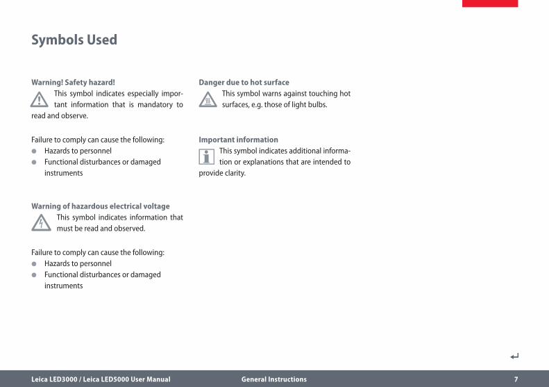
Warning! Safety hazard!
• This symbol indicates especially impor-tant information that is mandatory to
read and observe.
Failure to comply can cause the following: O Hazards to personnel O Functional disturbances or damaged
instruments
Warning of hazardous electrical voltage
This symbol indicates information that must be read and observed.
Failure to comply can cause the following: O Hazards to personnel O Functional disturbances or damaged
instruments
Danger due to hot surface
This symbol warns against touching hot surfaces, e.g. those of light bulbs.
Important information
This symbol indicates additional informa-tion or explanations that are intended to
provide clarity.

Leica LED3000 / Leica LED5000 User Manual General Instructions 8
Safety Instructions
Description O The Leica LED3000 and Leica LED5000
illuminators are supplements for Leica stereomicroscopes of the S series (Leica S4; Leica S6; Leica S8 Apo); M series (Leica M50, Leica M60, Leica M80) and DMS series (Leica DMS300 and Leica DMS1000). Illumi-nation by power LEDs ensures ideal light conditions and is used in a wide variety of applications.
Intended use O Refer to “Safety Concept” booklet
Non-intended use O Refer to “Safety Concept” booklet
Never use the Leica LED3000 and LED5000 illuminators and its components for IvD / IvF and/or medical applications, since they are not intended for these.
The instruments and accessories described in this User Manual have been tested for safety and potential hazards. The responsible Leica affiliate must be consulted whenever the instrument is altered, modified or used in conjunction with non-Leica components that are outside of the scope of this manual!
Unauthorized alterations to the instrument or noncompliant use shall void all rights to any warranty claims.
Place of use O Refer to “Safety Concept” booklet
O Electrical components must be placed at least 10 cm away from the wall and from flammable substances.
O Avoid large temperature fluctuations, direct sunlight and vibrations. These conditions can distort measurements and micro-graphic images.
O In warm and warm-damp climatic zones, the individual components require special care in order to prevent the build-up of fungus.
Responsibilities of person in charge of instrument
O Refer to “Safety Concept” booklet
Ensure that: O The Leica LED3000 and LED5000 illumina-
tors and accessories are operated, main-tained and repaired by authorized and trained personnel only.
O All operators have read, understood and observe this User Manual, and particularly the safety regulations.
Leica LED3000 / Leica LED5000 User Manual General Instructions 9
Safety Instructions (Continued)
Repairs, service work O Refer to “Safety Concept” booklet
O Only original Leica Microsystems spare parts may be used.
O Before opening the instruments, switch off the power and unplug the power cable.
O Avoid contact with powered electrical circuits, which can lead to injury.
Transport O Use the original packaging for shipping or
transporting the individual modules of the Leica LED3000 and LED5000 illuminators and the accessory components.
O In order to prevent damage from vibrations, disassemble all moving parts that (accord-ing to the user manual) can be assembled and disassembled by the customer and pack them separately.
Integration in third-party products O Refer to “Safety Concept” booklet
Disposal O Refer to “Safety Concept” booklet
Legal regulations O Refer to “Safety Concept” booklet
EC Declaration of Conformity O Refer to “Safety Concept” booklet
Health risksWorkplaces with microscopes facilitate and improve the viewing task, but they also impose high demands on the eyes and holding muscles of the user. Depending on the duration of unin-terrupted work, asthenopia and musculoskel-etal problems may occur. For this reason, appro-priate measures for reduction of the workload must be taken:
O Optimal arrangement of workplace, work assignments and work flow (changing tasks frequently).
O Thorough training of the personnel, giving consideration to ergonomic and organiza-tional aspects.
The ergonomic design of the Leica LED3000 and LED5000 illuminators aims to limit the strain on the user to the lowest possible level.
Leica LED3000 / Leica LED5000 User Manual About Leica LED Illuminators 10
About Leica LED Illuminators
Leica LED3000 / Leica LED5000 User Manual About Leica LED Illuminators 11
LED: Illuminant With a Future
Congratulations on purchasing your LED illumi-nator from Leica Microsystems. You have made an excellent choice: You will enjoy the high quality and well-conceived operation for a long time to come and it will provide the best pos-sible lighting for your work – regardless of the type of specimen you would like to examine.
All of the Leica LED illuminators offer a great number of advantages you will not want to do without:
O Constant color temperature (daylight) throughout the entire lifecycle
O Extremely long service life of up to 50 000 hours
O Absolutely maintenance-free; no lamp replacement required
O Depending on the illuminator, individual segments can be switched on or off inde-pendently from one another so that differ-ent illumination scenarios are possible.
O It is controlled either on the instrument, via the Leica SmartTouch panel or via the Leica Application Suite software.
O Extremely low power consumption at high light efficiency
The Leica LED illuminators work seamlessly with all Leica stereomicroscopes.
Using the Leica Application Suite software (LAS), users can control, save, and later call up scenarios with different microscope and light settings at the touch of a button.
We wish you great joy and success with your new LED illuminator by Leica Microsystems!
Leica LED3000 / Leica LED5000 User Manual About Leica LED Illuminators 12
Control via LAS and Leica SmartTouch
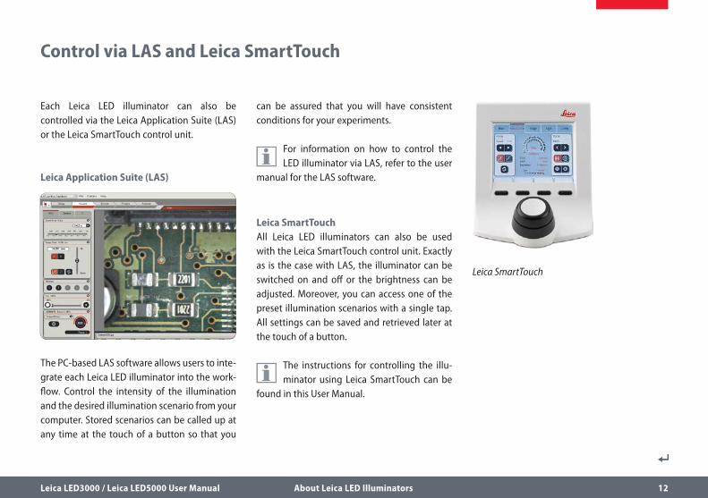
Each Leica LED illuminator can also be controlled via the Leica Application Suite (LAS) or the Leica SmartTouch control unit.
Leica Application Suite (LAS)
The PC-based LAS software allows users to inte-grate each Leica LED illuminator into the work-flow. Control the intensity of the illumination and the desired illumination scenario from your computer. Stored scenarios can be called up at any time at the touch of a button so that you
can be assured that you will have consistent conditions for your experiments.
For information on how to control the LED illuminator via LAS, refer to the user
manual for the LAS software.
Leica SmartTouchAll Leica LED illuminators can also be used with the Leica SmartTouch control unit. Exactly as is the case with LAS, the illuminator can be switched on and off or the brightness can be adjusted. Moreover, you can access one of the preset illumination scenarios with a single tap. All settings can be saved and retrieved later at the touch of a button.
The instructions for controlling the illu-minator using Leica SmartTouch can be
found in this User Manual.
Leica SmartTouch
Leica LED3000 / Leica LED5000 User Manual About Leica LED Illuminators 13
“Power PLUS function“ of the Illuminators
The Leica LED3000 and Leica LED5000 illumina-tors must be switched on separately, after the microscopy system is switched on. If the illumi-nator is to switch on automatically, the “Power PLUS function“ must be activated. The illumina-tor is automatically switched on if the illumina-tor is powered (e.g. by means of the CAN bus of the focusing column).
The following illuminators are equipped with “Power PLUS function”:
O Leica LED3000 RL
O Leica LED5000 RL
O Leica LED3000 SLI
O Leica LED5000 SLI
O Leica LED3000 NVI
O Leica LED5000 CXI
O Leica LED5000 NVI
O Leica LED5000 HDI
Activating and deactivating the “Power PLUS function” To activate the “Power PLUS function,” keep the plus button of the illuminator pressed while you connect the illuminator with the AC plug. The illuminator flashes quickly three times, showing that the function was activated.
To deactivate the “Power PLUS function,” keep the minus button of the illuminator pressed, while you connect the illuminator with the AC plug. The illuminator flashes quickly two times, showing that the function was deacti-vated.
The function is deactivated in the factory condi-tion.

Leica LED3000 / Leica LED5000 User Manual Leica LED3000 RL 14
Leica LED3000 RL
Leica LED3000 / Leica LED5000 User Manual Leica LED3000 RL 15
About the Leica LED3000 RL
The Leica LED3000 RL (“Ring Light”) generates a very bright and homogenous incident light. The ring illuminator illuminates the specimen with 24 LEDs that can be switched on or off together or in various combinations.
The Leica LED 3000 RL can be used with any objectives that have an outer diam-
eter of 58 mm. The supported working distance is between 60 mm and 150 mm.
ControlsIt is controlled using either the integrated keypad or via the Leica Application Suite (LAS) or the Leica SmartTouch.
LAS and the Leica SmartTouch enable you to create fully reproducible illumination scenarios and automatically toggle between them. For additional information on controlling the illu-minator via LAS, please refer to the LAS online help.
Leica LED3000 / Leica LED5000 User Manual Leica LED3000 RL 16
Leica LED3000 RL: Assembly
Required tools O None
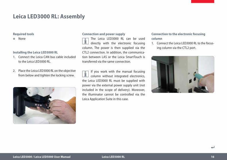
Installing the Leica LED3000 RL1. Connect the Leica CAN bus cable included
to the Leica LED3000 RL.
2. Place the Leica LED3000 RL on the objective from below and tighten the locking screw.
Connection and power supply
The Leica LED3000 RL can be used directly with the electronic focusing
column. The power is then supplied via the CTL2 connection. In addition, the communica-tion between LAS or the Leica SmartTouch is transferred via the same connection.
If you work with the manual focusing column without integrated electronics,
the Leica LED3000 RL must be supplied with power via the external power supply unit (not included in the scope of delivery). Moreover, the illuminator cannot be controlled via the Leica Application Suite in this case.
Connection to the electronic focusing column1. Connect the Leica LED3000 RL to the focus-
ing column via the CTL2 port.
Leica LED3000 / Leica LED5000 User Manual Leica LED3000 RL 17
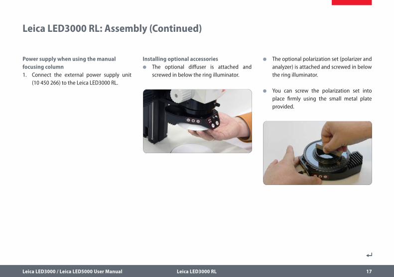
O The optional polarization set (polarizer and analyzer) is attached and screwed in below the ring illuminator.
O You can screw the polarization set into place firmly using the small metal plate provided.
Installing optional accessories O The optional diffuser is attached and
screwed in below the ring illuminator.
Power supply when using the manual focusing column1. Connect the external power supply unit
(10 450 266) to the Leica LED3000 RL.
Leica LED3000 RL: Assembly (Continued)
Leica LED3000 / Leica LED5000 User Manual Leica LED3000 RL 18
Leica LED3000 RL: Use
The light of the Leica LED3000 RL can be very bright. Therefore, always switch
on the illuminator before you look through the eyepieces! Avoid looking directly into the LEDs.
Using the keypad O Use the key to switch the Leica LED3000
RL illuminator on or off.
O Use the and keys to adjust the bright-ness in 10 increments.
O Touch either of the two keys to adjust the quantity of light in small increments.
O Hold the key pressed to change the quan-tity of light more quickly.
The illumination scenariosYou can switch between different illumination scenarios (full ring, half ring, quarter rings, opposite quarter rings) using the key. The active illuminator segments are displayed on the front control panel field by means of LEDs.
Use the and keys to rotate the active segments clockwise or counterclockwise.
Leica LED3000 / Leica LED5000 User Manual Leica LED3000 RL 19
Leica LED3000 RL and Leica SmartTouch
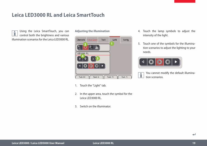
Using the Leica SmartTouch, you can control both the brightness and various
illumination scenarios for the Leica LED3000 RL.
Adjusting the illumination
1. Touch the “Light“ tab.
2. In the upper area, touch the symbol for the Leica LED3000 RL.
3. Switch on the illuminator.
4. Touch the lamp symbols to adjust the intensity of the light.
5. Touch one of the symbols for the illumina-tion scenarios to adjust the lighting to your needs.
You cannot modify the default illumina-tion scenarios.
Leica LED3000 / Leica LED5000 User Manual Leica LED3000 RL 20
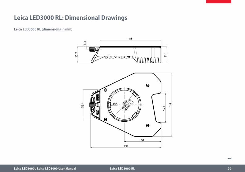
Leica LED3000 RL: Dimensional Drawings
Leica LED3000 RL (dimensions in mm)
Leica LED3000 / Leica LED5000 User Manual Leica LED5000 RL 21
Leica LED5000 RL
Leica LED3000 / Leica LED5000 User Manual Leica LED5000 RL 22
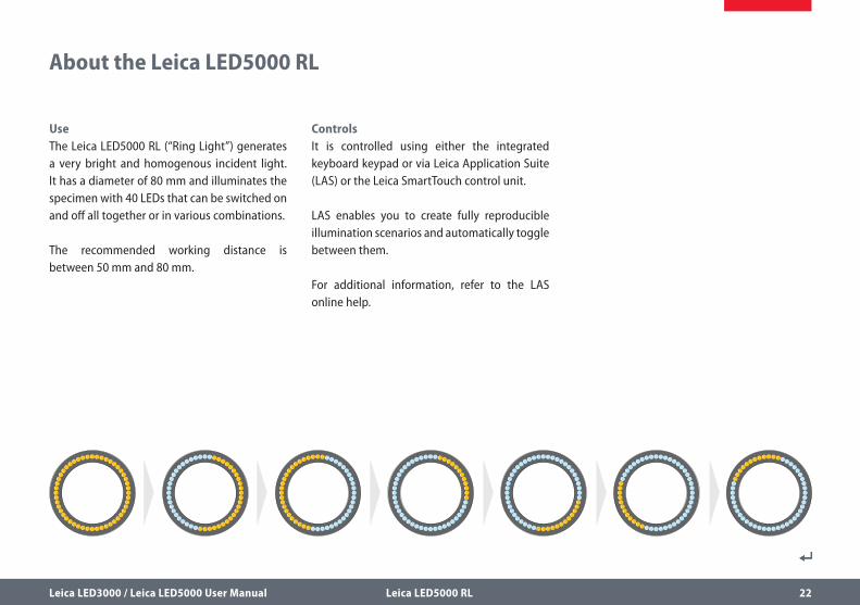
UseThe Leica LED5000 RL (“Ring Light”) generates a very bright and homogenous incident light. It has a diameter of 80 mm and illuminates the specimen with 40 LEDs that can be switched on and off all together or in various combinations.
The recommended working distance is between 50 mm and 80 mm.
About the Leica LED5000 RL
ControlsIt is controlled using either the integrated keyboard keypad or via Leica Application Suite (LAS) or the Leica SmartTouch control unit.
LAS enables you to create fully reproducible illumination scenarios and automatically toggle between them.
For additional information, refer to the LAS online help.
Leica LED3000 / Leica LED5000 User Manual Leica LED5000 RL 23
Leica LED5000 RL: Assembly
Required tools O None
The Leica LED5000 RL is installed on the objective using a single screw. It has
been optimized for a working distance between 50 mm and 80 mm.
ConstraintsThe Leica LED5000 RL can be used only in conjunction with the planapochromat 1× and planapochromat 0.63× objectives. With all other objectives, the working distance is too low for adequate illumination.
The ring illuminator cannot be used together with the objective nosepiece.
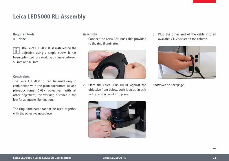
Assembly1. Connect the Leica CAN bus cable provided
to the ring illuminator.
2. Place the Leica LED5000 RL against the objective from below, push it up as far as it will go and screw it into place.
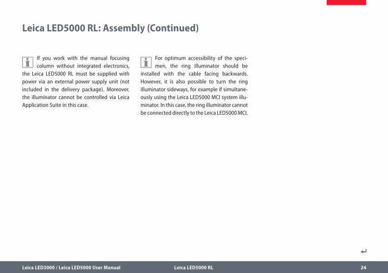
3. Plug the other end of the cable into an available CTL2 socket on the column.
Continued on next page.
Leica LED3000 / Leica LED5000 User Manual Leica LED5000 RL 24
Leica LED5000 RL: Assembly (Continued)
For optimum accessibility of the speci-men, the ring illuminator should be
installed with the cable facing backwards. However, it is also possible to turn the ring illuminator sideways, for example if simultane-ously using the Leica LED5000 MCI system illu-minator. In this case, the ring illuminator cannot be connected directly to the Leica LED5000 MCI.
If you work with the manual focusing column without integrated electronics,
the Leica LED5000 RL must be supplied with power via an external power supply unit (not included in the delivery package). Moreover, the illuminator cannot be controlled via Leica Application Suite in this case.
Leica LED3000 / Leica LED5000 User Manual Leica LED5000 RL 25
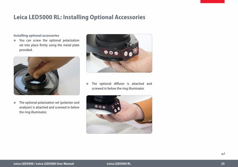
Installing optional accessories O You can screw the optional polarization
set into place firmly using the metal plate provided.
O The optional polarization set (polarizer and analyzer) is attached and screwed in below the ring illuminator.
O The optional diffuser is attached and screwed in below the ring illuminator.
Leica LED5000 RL: Installing Optional Accessories
Leica LED3000 / Leica LED5000 User Manual Leica LED5000 RL 26
Leica LED5000 RL: Use
The light of the Leica LED5000 RL can be very bright. Therefore, always switch
on the illuminator before you look through the eyepieces! Avoid looking directly into the LEDs.
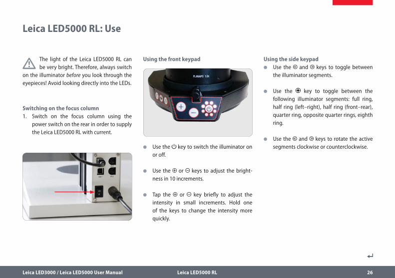
Switching on the focus column1. Switch on the focus column using the
power switch on the rear in order to supply the Leica LED5000 RL with current.
Using the front keypad
O Use the key to switch the illuminator on or off.
O Use the or keys to adjust the bright-ness in 10 increments.
O Tap the or key briefly to adjust the intensity in small increments. Hold one of the keys to change the intensity more quickly.
Using the side keypad O Use the and keys to toggle between
the illuminator segments.
O Use the key to toggle between the following illuminator segments: full ring, half ring (left–right), half ring (front–rear), quarter ring, opposite quarter rings, eighth ring.
O Use the and keys to rotate the active segments clockwise or counterclockwise.
Leica LED3000 / Leica LED5000 User Manual Leica LED5000 RL 27
Leica LED5000 RL: Use (Continued)
O If you press or for approx. 2 seconds, the segments rotate automatically until you press one of these keys again. If you change the segment using the key, the automatic changeover is kept. Pressing or briefly stops the changeover.
O Press and hold the key for approx. 2 seconds to switch on the full ring of the ring illuminator.
The active illuminator segments are indicated on the front control panel by 8
LEDs arranged around the on/off key.
Leica LED3000 / Leica LED5000 User Manual Leica LED5000 RL 28
Leica LED5000 RL and Leica SmartTouch
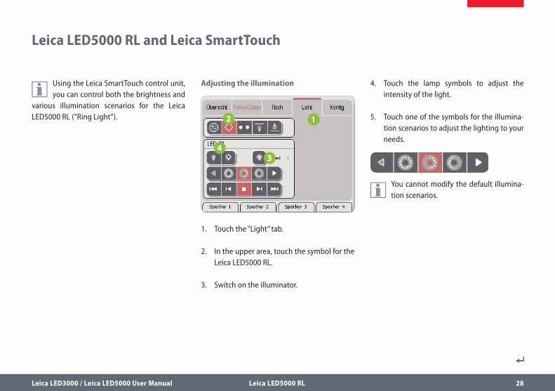
Using the Leica SmartTouch control unit, you can control both the brightness and
various illumination scenarios for the Leica LED5000 RL (“Ring Light”).
Adjusting the illumination
1. Touch the “Light” tab.
2. In the upper area, touch the symbol for the Leica LED5000 RL.
3. Switch on the illuminator.
4. Touch the lamp symbols to adjust the intensity of the light.
5. Touch one of the symbols for the illumina-tion scenarios to adjust the lighting to your needs.
You cannot modify the default illumina-tion scenarios.
132
132
160
37
160
37
58 mm
Leica LED3000 / Leica LED5000 User Manual Leica LED5000 RL 29
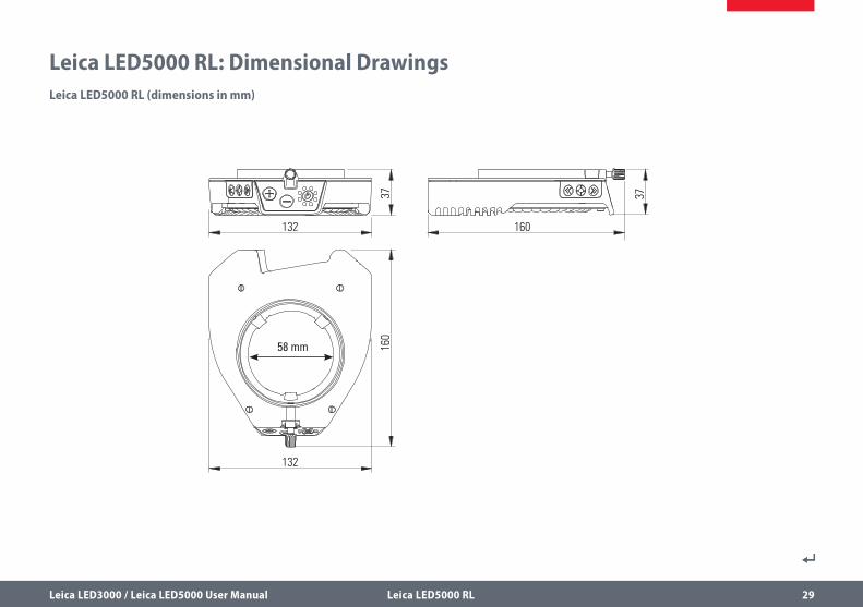
Leica LED5000 RL: Dimensional DrawingsLeica LED5000 RL (dimensions in mm)

Leica LED3000 / Leica LED5000 User Manual Leica LED3000 NVI 30
Leica LED3000 NVI
Leica LED3000 / Leica LED5000 User Manual Leica LED3000 NVI 31
Leica LED3000 NVI – The vertical LED light solutionUnlike coaxial illumination, the Leica LED3000 NVI also works for uneven specimens and specimens that have weak reflection. It is ideally suited for viewing recesses and bores. Minimized shadows caused by tools also contribute to an easier and more pleasing work experience with the microscope.
About the Leica LED3000 NVI
Leica LED3000 / Leica LED5000 User Manual Leica LED3000 NVI 32
Leica LED3000 NVI: Assembly
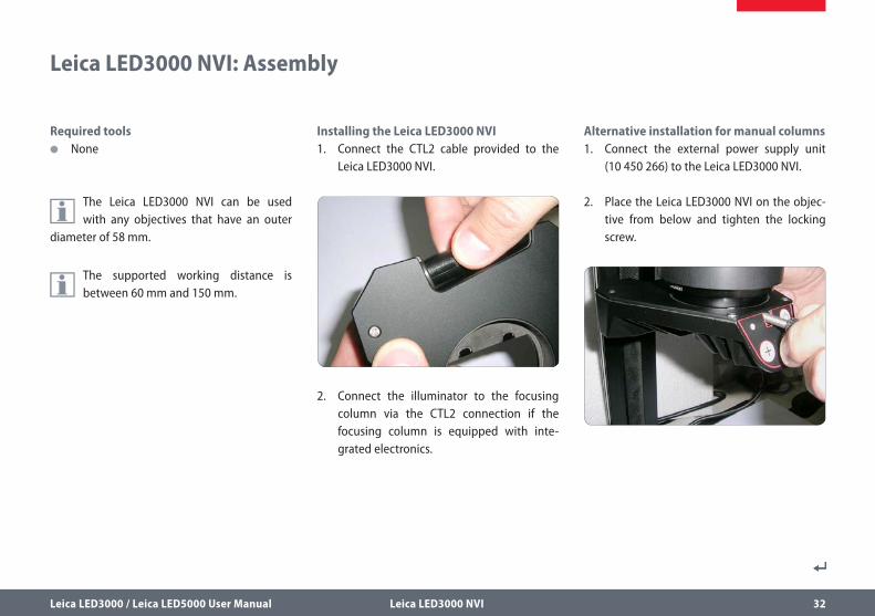
Required tools O None
The Leica LED3000 NVI can be used with any objectives that have an outer
diameter of 58 mm.
The supported working distance is between 60 mm and 150 mm.
Installing the Leica LED3000 NVI1. Connect the CTL2 cable provided to the
Leica LED3000 NVI.
2. Connect the illuminator to the focusing column via the CTL2 connection if the focusing column is equipped with inte-grated electronics.
Alternative installation for manual columns1. Connect the external power supply unit
(10 450 266) to the Leica LED3000 NVI.
2. Place the Leica LED3000 NVI on the objec-tive from below and tighten the locking screw.
Leica LED3000 / Leica LED5000 User Manual Leica LED3000 NVI 33
Leica LED3000 NVI: Assembly (Continued)
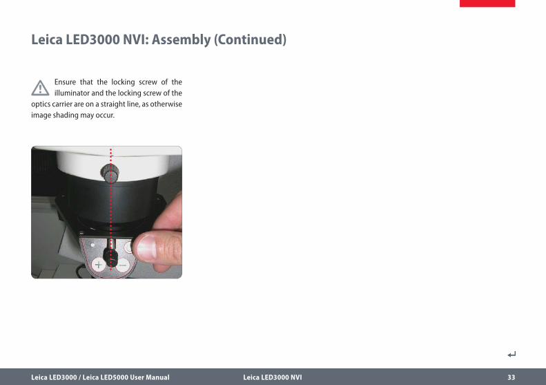
Ensure that the locking screw of the illuminator and the locking screw of the
optics carrier are on a straight line, as otherwise image shading may occur.
Leica LED3000 / Leica LED5000 User Manual Leica LED3000 NVI 34
Leica LED3000 NVI: Use
The intensity of the illuminator can be adjusted in 10 increments.
The control can also be controlled via Leica Application Suite (LAS) or the Leica
SmartTouch.
The supported working distance is between 60 mm and 150 mm.
When pressing the keys, hold the keypad between your thumb and index
finger. Avoid tapping the keypad with just one finger if possible.
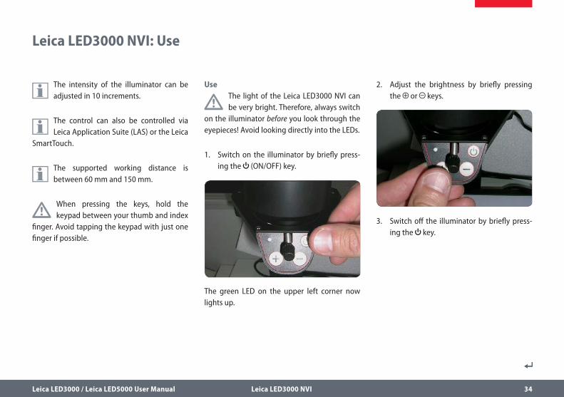
Use
The light of the Leica LED3000 NVI can be very bright. Therefore, always switch
on the illuminator before you look through the eyepieces! Avoid looking directly into the LEDs.
1. Switch on the illuminator by briefly press-ing the (ON/OFF) key.
The green LED on the upper left corner now lights up.
2. Adjust the brightness by briefly pressing the or keys.
3. Switch off the illuminator by briefly press-ing the key.

Leica LED3000 / Leica LED5000 User Manual Leica LED3000 NVI 35
Leica LED3000 NVI and Leica SmartTouch
Adjusting the illumination
1. Touch the “Light” tab.
2. In the upper area, touch the symbol of the Leica LED3000 NVI.
3. Switch on the illuminator.
4. Touch the lamp symbols to adjust the intensity of the light.
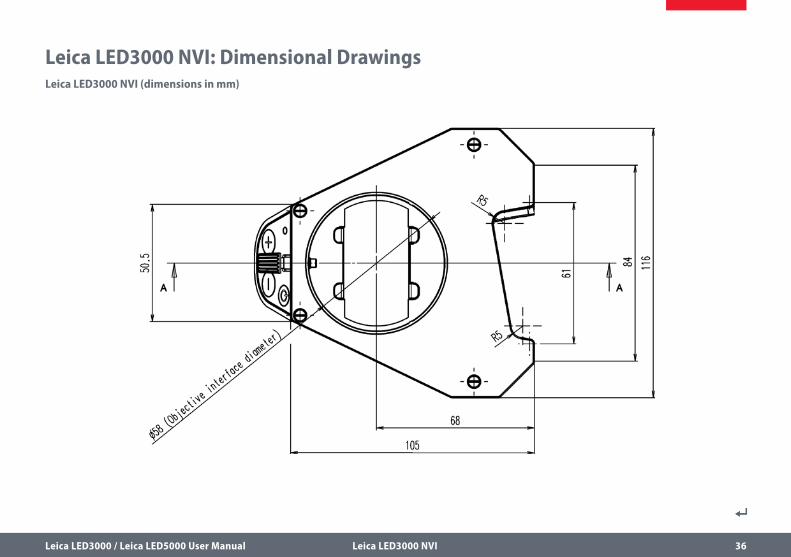
Leica LED3000 / Leica LED5000 User Manual Leica LED3000 NVI 36
Leica LED3000 NVI: Dimensional DrawingsLeica LED3000 NVI (dimensions in mm)
Leica LED3000 / Leica LED5000 User Manual Leica LED5000 NVI 37
Leica LED5000 NVI
Leica LED3000 / Leica LED5000 User Manual Leica LED5000 NVI 38
About the Leica LED5000 NVI
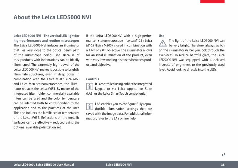
Leica LED5000 NVI – The vertical LED light for high-performance and routine microscopes The Leica LED5000 NVI induces an illuminator that lies very close to the optical beam path of the microscope being used. Because of this, products with indentations can be ideally illuminated. The extremely high power of the Leica LED5000 NVI makes it possible to brightly illuminate structures, even in deep bores. In combination with the Leica M50 / Leica M60 and Leica M80 stereomicroscopes, the illumi-nator replaces the Leica M651. By means of the integrated filter holder, commercially available filters can be used and the color temperature can be adapted both to corresponding to the application and to the practices of the user. This also induces the familiar color temperature of the Leica M651. Reflections on the metallic surfaces can be effectively reduced using the optional available polarization set.
If the Leica LED5000 NVI with a high-perfor-mance stereomicroscope (Leica M125 / Leica M165 /Leica M205) is used in combination with a 1.6× or 2.0× objective, the illuminator allows for an ideal illumination of the product, even with very low working distances between prod-uct and objective.
Controls
It is controlled using either the integrated keypad or via Leica Application Suite
(LAS) or the Leica SmartTouch control unit.
LAS enables you to configure fully repro-ducible illumination settings that are
saved with the image data. For additional infor-mation, refer to the LAS online help.
Use
The light of the Leica LED5000 NVI can be very bright. Therefore, always switch
on the illuminator before you look through the eyepieces! To reduce harmful glare, the Leica LED5000 NVI was equipped with a delayed increase of brightness to the previously used level. Avoid looking directly into the LEDs.
Leica LED3000 / Leica LED5000 User Manual Leica LED5000 NVI 39
Leica LED5000 NVI: Assembly on Routine Stereomicroscopes(Leica M50 / Leica M60 / Leica M80)
Required tools O Allen key M4 for assembly on the focusing
column
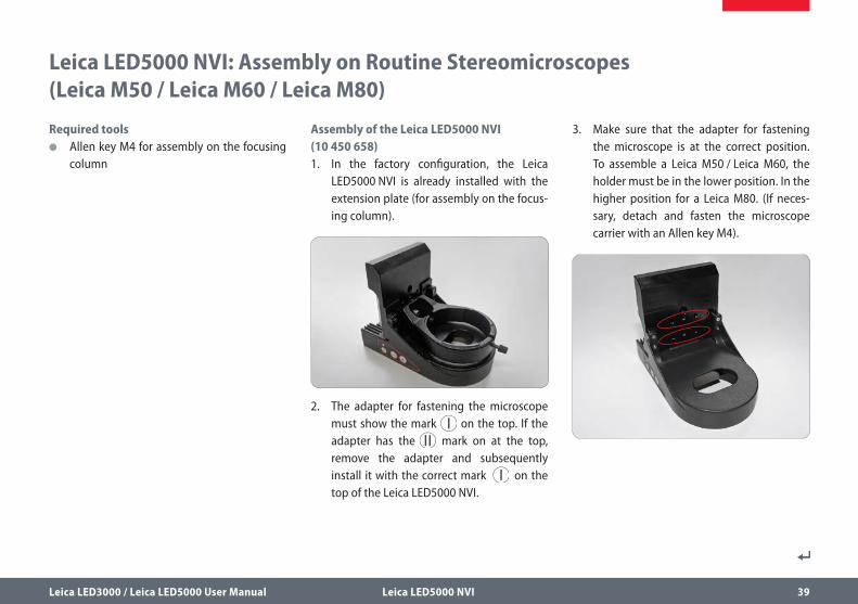
Assembly of the Leica LED5000 NVI (10 450 658)1. In the factory configuration, the Leica
LED5000 NVI is already installed with the extension plate (for assembly on the focus-ing column).
2. The adapter for fastening the microscope must show the mark on the top. If the adapter has the mark on at the top, remove the adapter and subsequently install it with the correct mark on the top of the Leica LED5000 NVI.
3. Make sure that the adapter for fastening the microscope is at the correct position. To assemble a Leica M50 / Leica M60, the holder must be in the lower position. In the higher position for a Leica M80. (If neces-sary, detach and fasten the microscope carrier with an Allen key M4).
Leica LED3000 / Leica LED5000 User Manual Leica LED5000 NVI 40
Leica LED5000 NVI: Assembly on Routine Stereomicroscopes (Leica M50 / Leica M60 / Leica M80) (Continued)
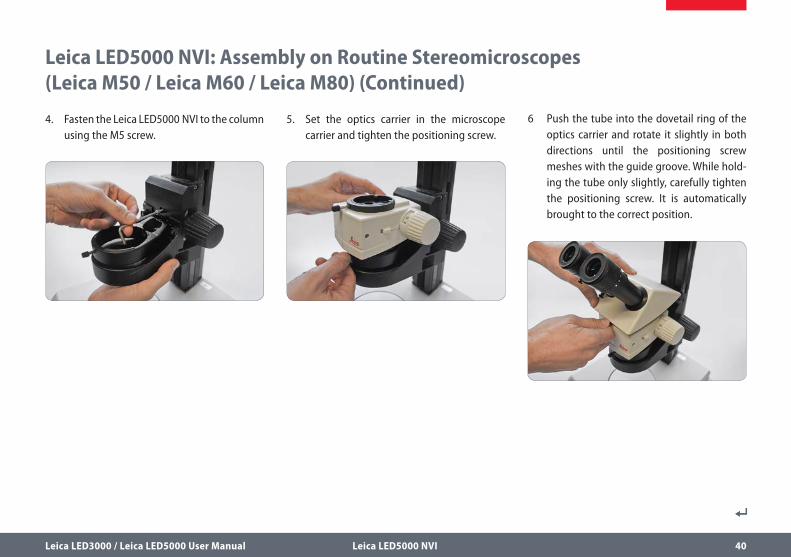
4. Fasten the Leica LED5000 NVI to the column using the M5 screw.
5. Set the optics carrier in the microscope carrier and tighten the positioning screw.
6 Push the tube into the dovetail ring of the optics carrier and rotate it slightly in both directions until the positioning screw meshes with the guide groove. While hold-ing the tube only slightly, carefully tighten the positioning screw. It is automatically brought to the correct position.
Leica LED3000 / Leica LED5000 User Manual Leica LED5000 NVI 41
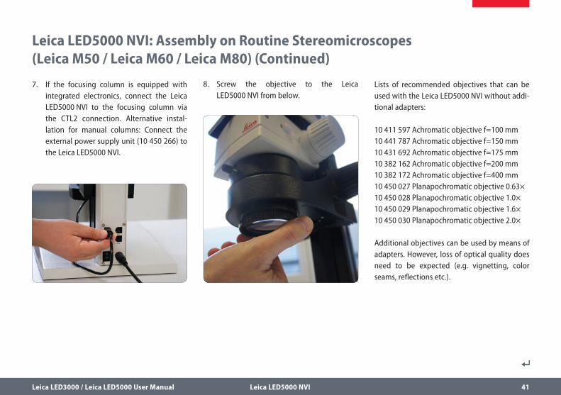
8. Screw the objective to the Leica LED5000 NVI from below.
Leica LED5000 NVI: Assembly on Routine Stereomicroscopes (Leica M50 / Leica M60 / Leica M80) (Continued)
7. If the focusing column is equipped with integrated electronics, connect the Leica LED5000 NVI to the focusing column via the CTL2 connection. Alternative instal-lation for manual columns: Connect the external power supply unit (10 450 266) to the Leica LED5000 NVI.
Lists of recommended objectives that can be used with the Leica LED5000 NVI without addi-tional adapters:
10 411 597 Achromatic objective f=100 mm10 441 787 Achromatic objective f=150 mm10 431 692 Achromatic objective f=175 mm10 382 162 Achromatic objective f=200 mm10 382 172 Achromatic objective f=400 mm10 450 027 Planapochromatic objective 0.63×10 450 028 Planapochromatic objective 1.0×10 450 029 Planapochromatic objective 1.6×10 450 030 Planapochromatic objective 2.0×
Additional objectives can be used by means of adapters. However, loss of optical quality does need to be expected (e.g. vignetting, color seams, reflections etc.).
Leica LED3000 / Leica LED5000 User Manual Leica LED5000 NVI 42
Leica LED5000 NVI: Assembly on Routine Stereomicroscopes(Leica M50 / Leica M60 / Leica M80) (Continued)
If you work with the standard achro-matic objectives of the M series instru-
ments (Leica M50 / Leica M60 / Leica M80), the illuminated surface will be smaller than the object field when in the low zoom range (up to a zoom position of 1.25×). This is due to the small diameter of the objectives and is not a malfunction. To prevent this effect, we recom-mended using the objectives listed above.
Leica LED3000 / Leica LED5000 User Manual Leica LED5000 NVI 43
Leica LED5000 NVI: Assembly on High-Performance Stereomicroscopes (Leica M125 / Leica M165 / Leica M205)
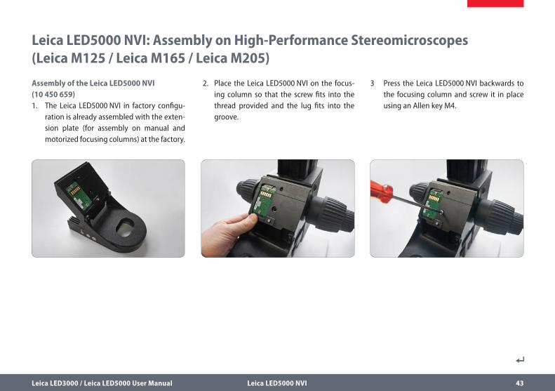
Assembly of the Leica LED5000 NVI (10 450 659)1. The Leica LED5000 NVI in factory configu-
ration is already assembled with the exten-sion plate (for assembly on manual and motorized focusing columns) at the factory.
2. Place the Leica LED5000 NVI on the focus-ing column so that the screw fits into the thread provided and the lug fits into the groove.
3 Press the Leica LED5000 NVI backwards to the focusing column and screw it in place using an Allen key M4.
Leica LED3000 / Leica LED5000 User Manual Leica LED5000 NVI 44
Leica LED5000 NVI: Assembly on High-Performance Stereomicroscopes (Leica M125 / Leica M165 / Leica M205) (Continued)
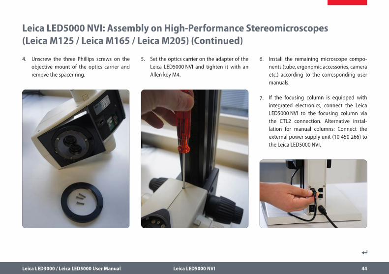
4. Unscrew the three Phillips screws on the objective mount of the optics carrier and remove the spacer ring.
5. Set the optics carrier on the adapter of the Leica LED5000 NVI and tighten it with an Allen key M4.
6. Install the remaining microscope compo-nents (tube, ergonomic accessories, camera etc.) according to the corresponding user manuals.
7. If the focusing column is equipped with integrated electronics, connect the Leica LED5000 NVI to the focusing column via the CTL2 connection. Alternative instal-lation for manual columns: Connect the external power supply unit (10 450 266) to the Leica LED5000 NVI.
Leica LED3000 / Leica LED5000 User Manual Leica LED5000 NVI 45
Leica LED5000 NVI: Assembly on High-Performance Stereomicroscopes (Leica M125 / Leica M165 / Leica M205) (Continued)
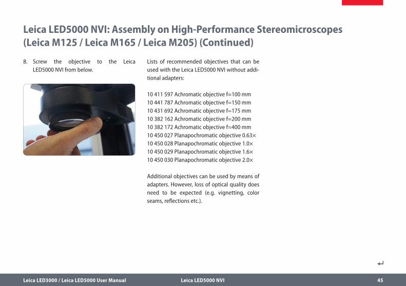
8. Screw the objective to the Leica LED5000 NVI from below.
Lists of recommended objectives that can be used with the Leica LED5000 NVI without addi-tional adapters:
10 411 597 Achromatic objective f=100 mm10 441 787 Achromatic objective f=150 mm10 431 692 Achromatic objective f=175 mm10 382 162 Achromatic objective f=200 mm10 382 172 Achromatic objective f=400 mm10 450 027 Planapochromatic objective 0.63×10 450 028 Planapochromatic objective 1.0×10 450 029 Planapochromatic objective 1.6×10 450 030 Planapochromatic objective 2.0×
Additional objectives can be used by means of adapters. However, loss of optical quality does need to be expected (e.g. vignetting, color seams, reflections etc.).
Leica LED3000 / Leica LED5000 User Manual Leica LED5000 NVI 46
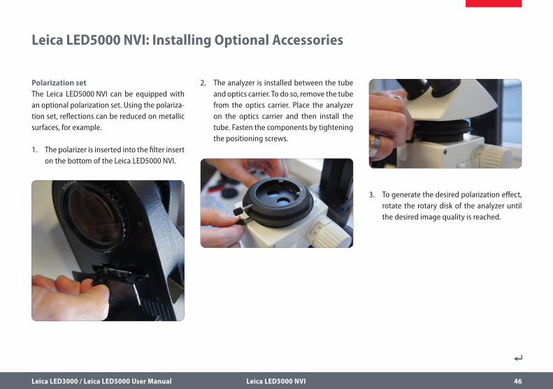
3. To generate the desired polarization effect, rotate the rotary disk of the analyzer until the desired image quality is reached.
Leica LED5000 NVI: Installing Optional Accessories
Polarization setThe Leica LED5000 NVI can be equipped with an optional polarization set. Using the polariza-tion set, reflections can be reduced on metallic surfaces, for example.
1. The polarizer is inserted into the filter insert on the bottom of the Leica LED5000 NVI.
2. The analyzer is installed between the tube and optics carrier. To do so, remove the tube from the optics carrier. Place the analyzer on the optics carrier and then install the tube. Fasten the components by tightening the positioning screws.
Leica LED3000 / Leica LED5000 User Manual Leica LED5000 NVI 47
Leica LED5000 NVI: Installing Optional Accessories (Continued)
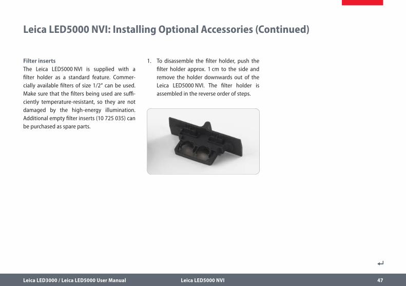
Filter insertsThe Leica LED5000 NVI is supplied with a filter holder as a standard feature. Commer-cially available filters of size 1/2“ can be used. Make sure that the filters being used are suffi-ciently temperature-resistant, so they are not damaged by the high-energy illumination. Additional empty filter inserts (10 725 035) can be purchased as spare parts.
1. To disassemble the filter holder, push the filter holder approx. 1 cm to the side and remove the holder downwards out of the Leica LED5000 NVI. The filter holder is assembled in the reverse order of steps.
Leica LED3000 / Leica LED5000 User Manual Leica LED5000 NVI 48
Use
The light of the Leica LED5000 NVI can be very bright. Therefore, always
switch on the illuminator before you look through the eyepieces! To avoid glare, the Leica LED5000 NVI was equipped with a delayed raise to the previously used brightness level. Avoid looking directly into the LEDs.
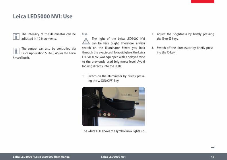
1. Switch on the illuminator by briefly press-ing the (ON/OFF) key.
The white LED above the symbol now lights up.
Leica LED5000 NVI: Use
The intensity of the illuminator can be adjusted in 10 increments.
The control can also be controlled via Leica Application Suite (LAS) or the Leica
SmartTouch.
2. Adjust the brightness by briefly pressing the or keys.
3. Switch off the illuminator by briefly press-ing the key.
Leica LED3000 / Leica LED5000 User Manual Leica LED5000 NVI 49
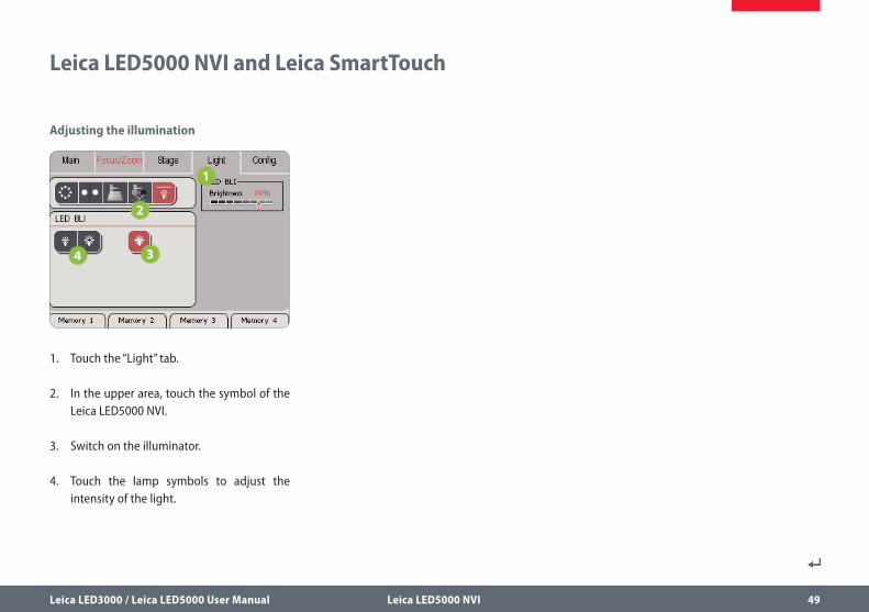
Leica LED5000 NVI and Leica SmartTouch
Adjusting the illumination
1. Touch the “Light” tab.
2. In the upper area, touch the symbol of the Leica LED5000 NVI.
3. Switch on the illuminator.
4. Touch the lamp symbols to adjust the intensity of the light.
Leica LED3000 / Leica LED5000 User Manual Leica LED5000 NVI 50
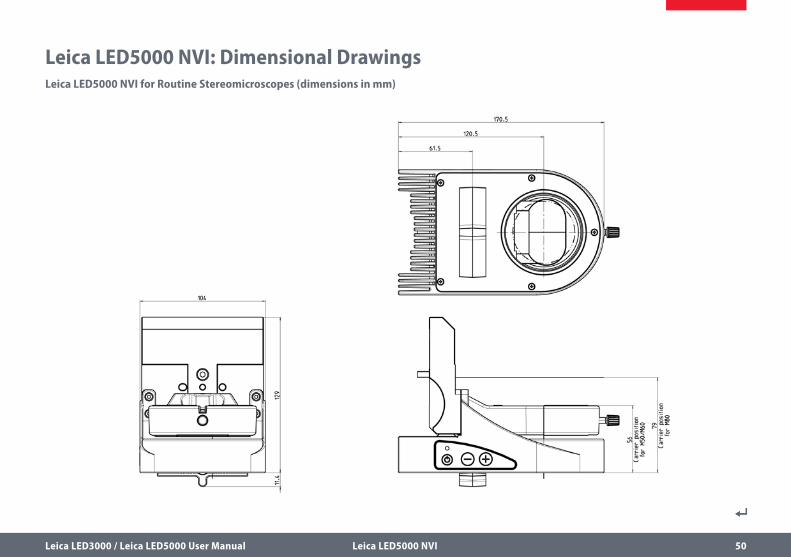
Leica LED5000 NVI: Dimensional DrawingsLeica LED5000 NVI for Routine Stereomicroscopes (dimensions in mm)
Leica LED3000 / Leica LED5000 User Manual Leica LED5000 NVI 51
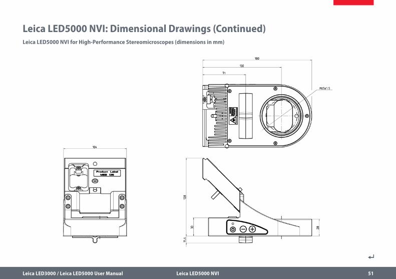
Leica LED5000 NVI: Dimensional Drawings (Continued)Leica LED5000 NVI for High-Performance Stereomicroscopes (dimensions in mm)

Leica LED3000 / Leica LED5000 User Manual Leica LED3000 MCI 52
Leica LED3000 MCI
Leica LED3000 / Leica LED5000 User Manual Leica LED3000 MCI 53
Use
Using the Leica LED3000 MCI (for “Multi- Contrast-Illumination”), reproducible in-
cident light settings with different contrast can be generated. Both illuminator arcs with the integrated LED spotlights can be moved into the desired position depending on the configu-ration (microscope and objective).
About the Leica LED3000 MCI
Leica LED3000 / Leica LED5000 User Manual Leica LED3000 MCI 54
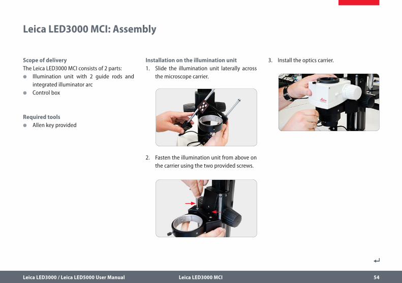
Scope of deliveryThe Leica LED3000 MCI consists of 2 parts:
O Illumination unit with 2 guide rods and integrated illuminator arc
O Control box
Required tools O Allen key provided
Installation on the illumination unit1. Slide the illumination unit laterally across
the microscope carrier.
2. Fasten the illumination unit from above on the carrier using the two provided screws.
3. Install the optics carrier.
Leica LED3000 MCI: Assembly
Leica LED3000 / Leica LED5000 User Manual Leica LED3000 MCI 55
Leica LED3000 MCI: Assembly (Continued)
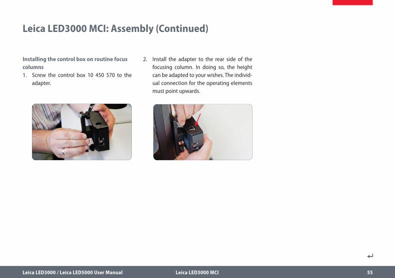
Installing the control box on routine focus columns1. Screw the control box 10 450 570 to the
adapter.
2. Install the adapter to the rear side of the focusing column. In doing so, the height can be adapted to your wishes. The individ-ual connection for the operating elements must point upwards.
Leica LED3000 / Leica LED5000 User Manual Leica LED3000 MCI 56
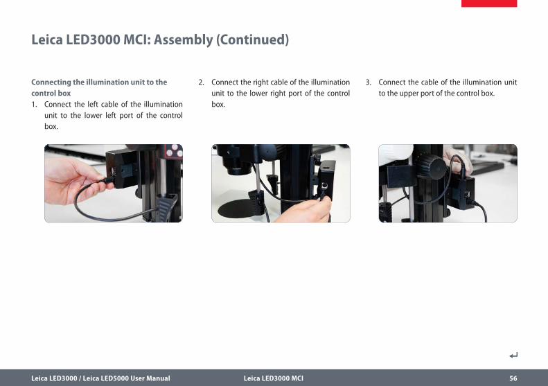
Connecting the illumination unit to the control box1. Connect the left cable of the illumination
unit to the lower left port of the control box.
2. Connect the right cable of the illumination unit to the lower right port of the control box.
Leica LED3000 MCI: Assembly (Continued)
3. Connect the cable of the illumination unit to the upper port of the control box.
Leica LED3000 / Leica LED5000 User Manual Leica LED3000 MCI 57
Leica LED3000 MCI: Assembly (Continued)
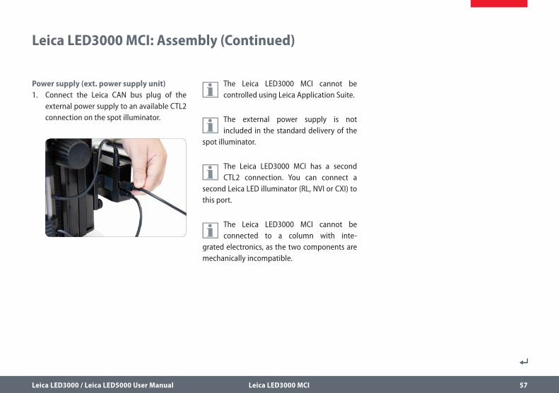
Power supply (ext. power supply unit)1. Connect the Leica CAN bus plug of the
external power supply to an available CTL2 connection on the spot illuminator.
The Leica LED3000 MCI cannot be controlled using Leica Application Suite.
The external power supply is not included in the standard delivery of the
spot illuminator.
The Leica LED3000 MCI has a second CTL2 connection. You can connect a
second Leica LED illuminator (RL, NVI or CXI) to this port.
The Leica LED3000 MCI cannot be connected to a column with inte-
grated electronics, as the two components are mechanically incompatible.
Leica LED3000 / Leica LED5000 User Manual Leica LED3000 MCI 58
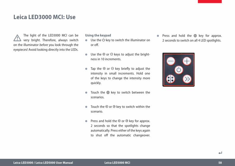
The light of the LED3000 MCI can be very bright. Therefore, always switch
on the illuminator before you look through the eyepieces! Avoid looking directly into the LEDs.
Using the keypad O Use the key to switch the illuminator on
or off.
O Use the or keys to adjust the bright-ness in 10 increments.
O Tap the or key briefly to adjust the intensity in small increments. Hold one of the keys to change the intensity more quickly.
O Touch the key to switch between the scenarios.
O Touch the or key to switch within the scenario.
O Press and hold the or key for approx. 2 seconds so that the spotlights change automatically. Press either of the keys again to shut off the automatic changeover.
O Press and hold the key for approx. 2 seconds to switch on all 4 LED spotlights.
Leica LED3000 MCI: Use
Leica LED3000 / Leica LED5000 User Manual Leica LED3000 MCI 59
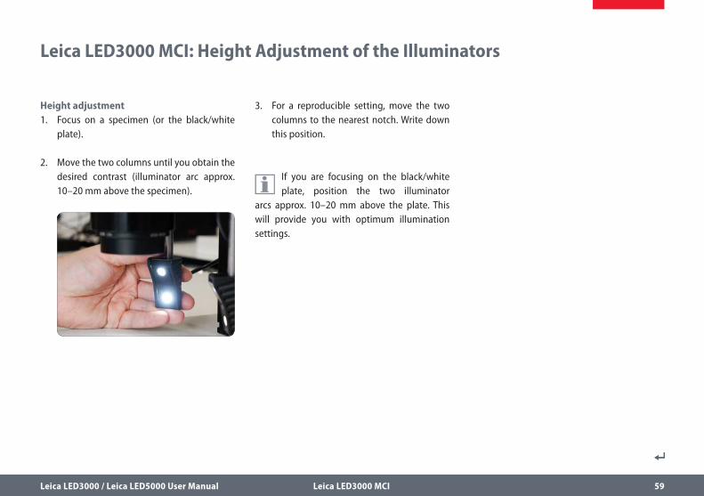
Height adjustment1. Focus on a specimen (or the black/white
plate).
2. Move the two columns until you obtain the desired contrast (illuminator arc approx. 10–20 mm above the specimen).
3. For a reproducible setting, move the two columns to the nearest notch. Write down this position.
If you are focusing on the black/white plate, position the two illuminator
arcs approx. 10–20 mm above the plate. This will provide you with optimum illumination settings.
Leica LED3000 MCI: Height Adjustment of the Illuminators
134
134
120 35 49
210
12
0
Leica LED3000 / Leica LED5000 User Manual Leica LED3000 MCI 60
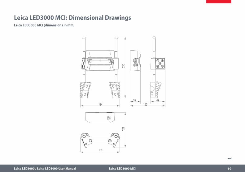
Leica LED3000 MCI: Dimensional DrawingsLeica LED3000 MCI (dimensions in mm)

Leica LED3000 / Leica LED5000 User Manual Leica LED5000 MCI 61
Leica LED5000 MCI
Leica LED3000 / Leica LED5000 User Manual Leica LED5000 MCI 62
About the Leica LED5000 MCI
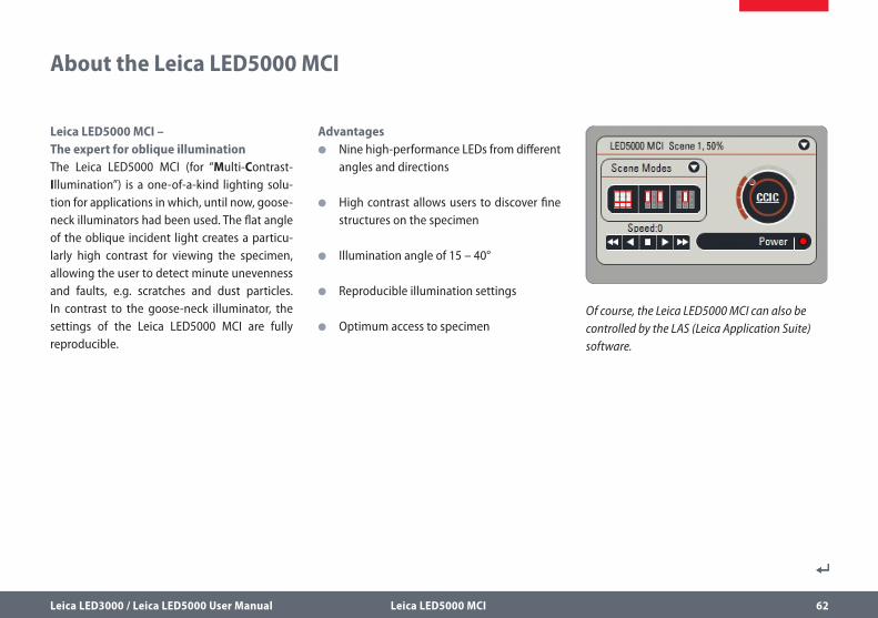
Leica LED5000 MCI – The expert for oblique illuminationThe Leica LED5000 MCI (for “Multi-Contrast- Illumination”) is a one-of-a-kind lighting solu-tion for applications in which, until now, goose-neck illuminators had been used. The flat angle of the oblique incident light creates a particu-larly high contrast for viewing the specimen, allowing the user to detect minute unevenness and faults, e.g. scratches and dust particles. In contrast to the goose-neck illuminator, the settings of the Leica LED5000 MCI are fully reproducible.
Advantages O Nine high-performance LEDs from different
angles and directions
O High contrast allows users to discover fine structures on the specimen
O Illumination angle of 15 – 40°
O Reproducible illumination settings
O Optimum access to specimenOf course, the Leica LED5000 MCI can also be controlled by the LAS (Leica Application Suite) software.
Leica LED3000 / Leica LED5000 User Manual Leica LED5000 MCI 63
Leica LED5000 MCI: Assembly
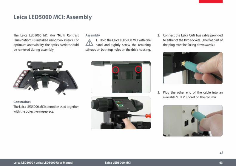
The Leica LED5000 MCI (for “Multi Contrast Illumination”) is installed using two screws. For optimum accessibility, the optics carrier should be removed during assembly.
ConstraintsThe Leica LED5000 MCI cannot be used together with the objective nosepiece.
Assembly
1. Hold the Leica LED5000 MCI with one hand and tightly screw the retaining
stirrups on both top holes on the drive housing.
2. Connect the Leica CAN bus cable provided to either of the two sockets. (The flat part of the plug must be facing downwards.)
3. Plug the other end of the cable into an available ”CTL2“ socket on the column.
Leica LED3000 / Leica LED5000 User Manual Leica LED5000 MCI 64
Leica LED5000 MCI: Alternative Assembly
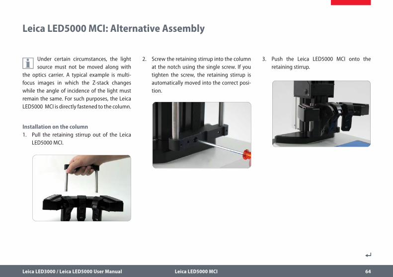
Under certain circumstances, the light source must not be moved along with
the optics carrier. A typical example is multi-focus images in which the Z-stack changes while the angle of incidence of the light must remain the same. For such purposes, the Leica LED5000 MCI is directly fastened to the column.
Installation on the column1. Pull the retaining stirrup out of the Leica
LED5000 MCI.
2. Screw the retaining stirrup into the column at the notch using the single screw. If you tighten the screw, the retaining stirrup is automatically moved into the correct posi-tion.
3. Push the Leica LED5000 MCI onto the retaining stirrup.
Leica LED3000 / Leica LED5000 User Manual Leica LED5000 MCI 65
PreparationHold the Leica LED5000 MCI with both hands and pull it downwards until it clicks into place on the bottom end of the guide rods. Make sure that the black plastic screw is installed for secur-ing on the left or right guide rod (see figure).
In this position, you always have the same contrast with identical illumina-
tion. This guarantees the reproducibility of an experiment.
If using the AX carrier, use the upper engaging position of the retaining stir-
rup.
The light of the Leica LED5000 MCI can be very bright. Therefore, always switch
on the illuminator before you look through the eyepieces! Avoid looking directly into the LEDs.
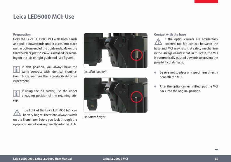
Contact with the base
• If the optics carriers are accidentally lowered too far, contact between the
base and MCI may result. A safety mechanism in the linkage ensures that, in this case, the MCI is automatically pushed upwards to prevent the possibility of damage.
O Be sure not to place any specimens directly beneath the MCI.
O After the optics carrier is lifted, put the MCI back into the original position.
Leica LED5000 MCI: Use
Installed too high
Optimum height
Leica LED3000 / Leica LED5000 User Manual Leica LED5000 MCI 66
Using the keypad O Use the key to switch the illuminator on
or off.
O Use the or keys to adjust the bright-ness in 10 increments. Tap either of the two keys to adjust the intensity in small incre-ments. Hold a key to change the intensity more quickly.
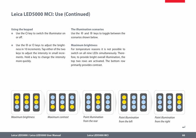
The illumination scenariosUse the and keys to toggle between the scenarios shown below.
Maximum brightnessFor temperature reasons it is not possible to switch on all nine LEDs simultaneously. There-fore, to provide bright overall illumination, the top two rows are activated. The bottom row primarily provides contrast.
Leica LED5000 MCI: Use (Continued)
Maximum brightness Point illumination from the right
Maximum contrast Point illumination from the left
Point illumination from the rear
Leica LED3000 / Leica LED5000 User Manual Leica LED5000 MCI 67
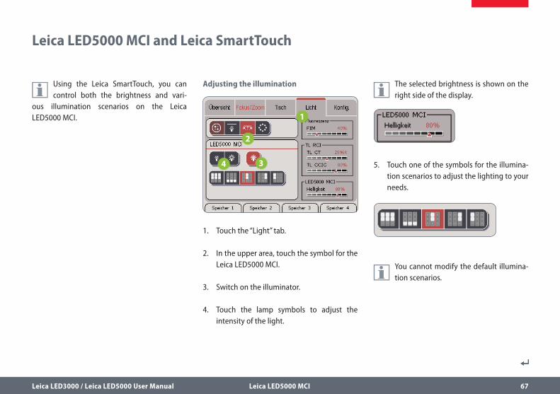
Leica LED5000 MCI and Leica SmartTouch
Using the Leica SmartTouch, you can control both the brightness and vari-
ous illumination scenarios on the Leica LED5000 MCI.
Adjusting the illumination
1. Touch the “Light” tab.
2. In the upper area, touch the symbol for the Leica LED5000 MCI.
3. Switch on the illuminator.
4. Touch the lamp symbols to adjust the intensity of the light.
The selected brightness is shown on the right side of the display.
5. Touch one of the symbols for the illumina-tion scenarios to adjust the lighting to your needs.
You cannot modify the default illumina-tion scenarios.
132
275.3
157
83.5
112
4511
2
90
45
3622
132
275.3
157
83.5
112
4511
2
90
45
3622
132
275.3
157
83.5
112
4511
2
90
45
3622
Leica LED3000 / Leica LED5000 User Manual Leica LED5000 MCI 68
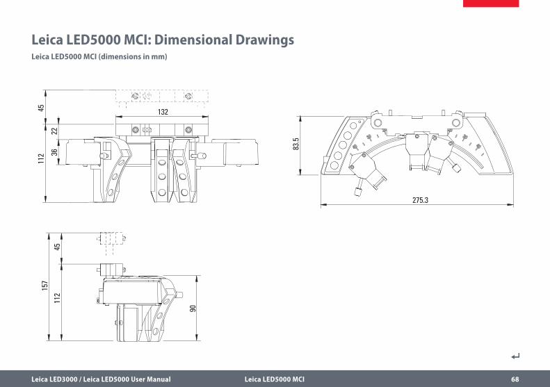
Leica LED5000 MCI: Dimensional DrawingsLeica LED5000 MCI (dimensions in mm)
Leica LED3000 / Leica LED5000 User Manual Leica LED5000 CXI 69
Leica LED5000 CXI
Leica LED3000 / Leica LED5000 User Manual Leica LED5000 CXI 70
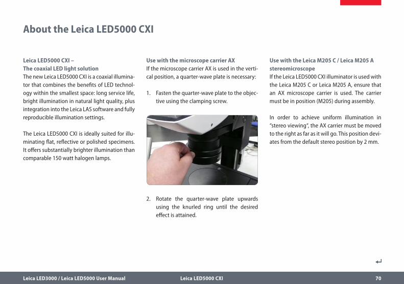
Leica LED5000 CXI – The coaxial LED light solutionThe new Leica LED5000 CXI is a coaxial illumina-tor that combines the benefits of LED technol-ogy within the smallest space: long service life, bright illumination in natural light quality, plus integration into the Leica LAS software and fully reproducible illumination settings.
The Leica LED5000 CXI is ideally suited for illu-minating flat, reflective or polished specimens. It offers substantially brighter illumination than comparable 150 watt halogen lamps.
Use with the microscope carrier AXIf the microscope carrier AX is used in the verti-cal position, a quarter-wave plate is necessary:
1. Fasten the quarter-wave plate to the objec-tive using the clamping screw.
2. Rotate the quarter-wave plate upwards using the knurled ring until the desired effect is attained.
Use with the Leica M205 C / Leica M205 A stereomicroscopeIf the Leica LED5000 CXI illuminator is used with the Leica M205 C or Leica M205 A, ensure that an AX microscope carrier is used. The carrier must be in position (M205) during assembly.
In order to achieve uniform illumination in “stereo viewing“, the AX carrier must be moved to the right as far as it will go. This position devi-ates from the default stereo position by 2 mm.
About the Leica LED5000 CXI
Leica LED3000 / Leica LED5000 User Manual Leica LED5000 CXI 71
Leica LED5000 CXI: Assembly
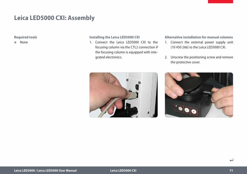
Required tools O None
Installing the Leica LED5000 CXI1. Connect the Leica LED5000 CXI to the
focusing column via the CTL2 connection if the focusing column is equipped with inte-grated electronics.
Alternative installation for manual columns1. Connect the external power supply unit
(10 450 266) to the Leica LED5000 CXI.
2. Unscrew the positioning screw and remove the protective cover.
Leica LED3000 / Leica LED5000 User Manual Leica LED5000 CXI 72
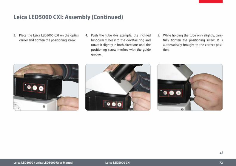
3. Place the Leica LED5000 CXI on the optics carrier and tighten the positioning screw.
4. Push the tube (for example, the inclined binocular tube) into the dovetail ring and rotate it slightly in both directions until the positioning screw meshes with the guide groove.
5. While holding the tube only slightly, care-fully tighten the positioning screw. It is automatically brought to the correct posi-tion.
Leica LED5000 CXI: Assembly (Continued)
Leica LED3000 / Leica LED5000 User Manual Leica LED5000 CXI 73
Leica LED5000 CXI: Use
The intensity of the illuminator can be adjusted in 10 increments.
The Leica LED5000 CXI can also be controlled via the Leica Application Suite
(LAS) or the Leica SmartTouch.
Using the Leica LED5000 CXI results in an increased magnification level of 1.5×.
Depending on the components used, different intensities of vignetting may
occur at low magnification. Vignetting is normal and not a malfunction.
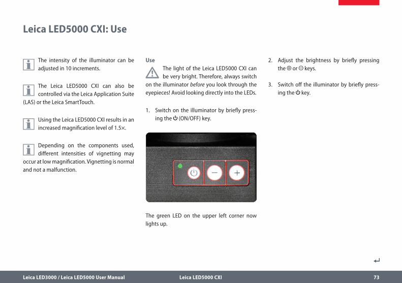
Use
The light of the Leica LED5000 CXI can be very bright. Therefore, always switch
on the illuminator before you look through the eyepieces! Avoid looking directly into the LEDs.
1. Switch on the illuminator by briefly press-ing the (ON/OFF) key.
The green LED on the upper left corner now lights up.
2. Adjust the brightness by briefly pressing the or keys.
3. Switch off the illuminator by briefly press-ing the key.
Leica LED3000 / Leica LED5000 User Manual Leica LED5000 CXI 74
Leica LED5000 CXI and Leica SmartTouch
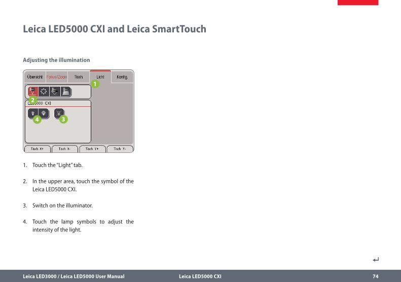
Adjusting the illumination
1. Touch the “Light” tab.
2. In the upper area, touch the symbol of the Leica LED5000 CXI.
3. Switch on the illuminator.
4. Touch the lamp symbols to adjust the intensity of the light.
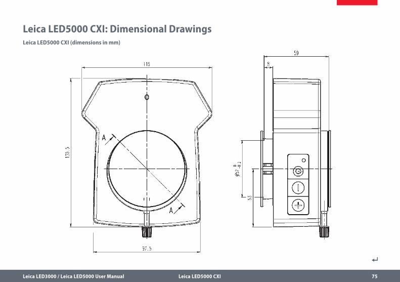
Leica LED3000 / Leica LED5000 User Manual Leica LED5000 CXI 75
Leica LED5000 CXI: Dimensional DrawingsLeica LED5000 CXI (dimensions in mm)

Leica LED3000 / Leica LED5000 User Manual Leica LED3000 BLI 76
Leica LED3000 BLI
Leica LED3000 / Leica LED5000 User Manual Leica LED3000 BLI 77
The Leica LED3000 BLI (for “Back Light Illumina-tion”) is suitable as a transmitted light illumina-tor for use in baseplates that do not have back light functions. Since the Leica LED3000 BLI is not permanently assembled on the base, it can be used very flexibly when needed. Due to the large, level surface, large products can be studied. With the inductive button, the Leica LED3000 BLI can be switched on and off and the brightness can be adjusted in 10 increments.
About the Leica LED3000 BLI
Leica LED3000 / Leica LED5000 User Manual Leica LED3000 BLI 78
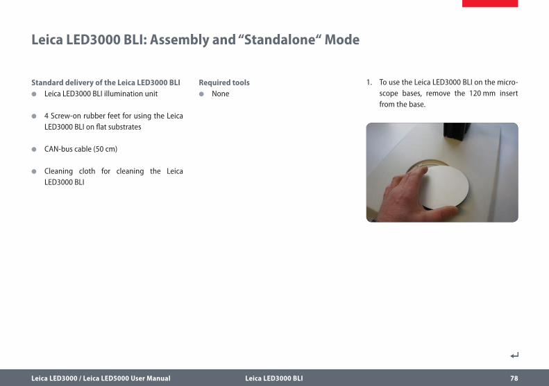
1. To use the Leica LED3000 BLI on the micro-scope bases, remove the 120 mm insert from the base.
Leica LED3000 BLI: Assembly and “Standalone“ Mode
Standard delivery of the Leica LED3000 BLI O Leica LED3000 BLI illumination unit
O 4 Screw-on rubber feet for using the Leica LED3000 BLI on flat substrates
O CAN-bus cable (50 cm)
O Cleaning cloth for cleaning the Leica LED3000 BLI
Required tools O None
Leica LED3000 / Leica LED5000 User Manual Leica LED3000 BLI 79
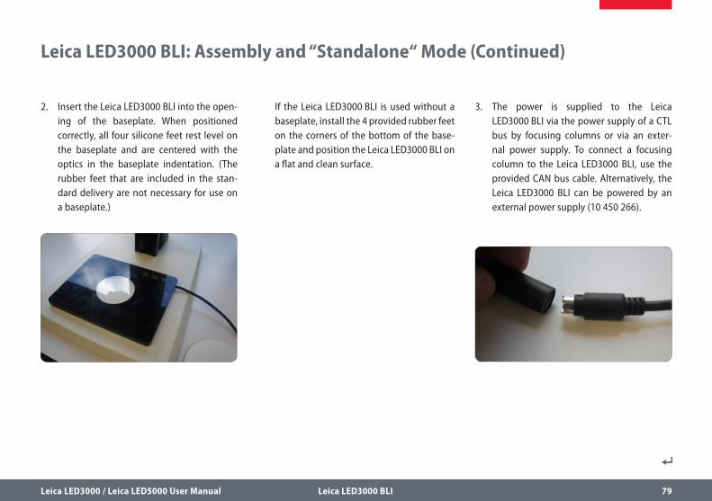
If the Leica LED3000 BLI is used without a baseplate, install the 4 provided rubber feet on the corners of the bottom of the base-plate and position the Leica LED3000 BLI on a flat and clean surface.
Leica LED3000 BLI: Assembly and “Standalone“ Mode (Continued)
2. Insert the Leica LED3000 BLI into the open-ing of the baseplate. When positioned correctly, all four silicone feet rest level on the baseplate and are centered with the optics in the baseplate indentation. (The rubber feet that are included in the stan-dard delivery are not necessary for use on a baseplate.)
3. The power is supplied to the Leica LED3000 BLI via the power supply of a CTL bus by focusing columns or via an exter-nal power supply. To connect a focusing column to the Leica LED3000 BLI, use the provided CAN bus cable. Alternatively, the Leica LED3000 BLI can be powered by an external power supply (10 450 266).
Leica LED3000 / Leica LED5000 User Manual Leica LED3000 BLI 80
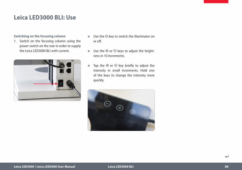
Leica LED3000 BLI: Use
Switching on the focusing column1. Switch on the focusing column using the
power switch on the rear in order to supply the Leica LED3000 BLI with current.
O Use the key to switch the illuminator on or off.
O Use the or keys to adjust the bright-ness in 10 increments.
O Tap the or key briefly to adjust the intensity in small increments. Hold one of the keys to change the intensity more quickly.
Leica LED3000 / Leica LED5000 User Manual Leica LED3000 BLI 81
Leica LED3000 BLI and Leica SmartTouch
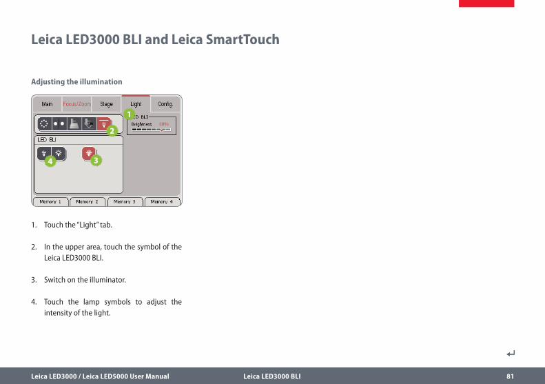
Adjusting the illumination
1. Touch the “Light” tab.
2. In the upper area, touch the symbol of the Leica LED3000 BLI.
3. Switch on the illuminator.
4. Touch the lamp symbols to adjust the intensity of the light.
Leica LED3000 / Leica LED5000 User Manual Leica LED3000 BLI 82
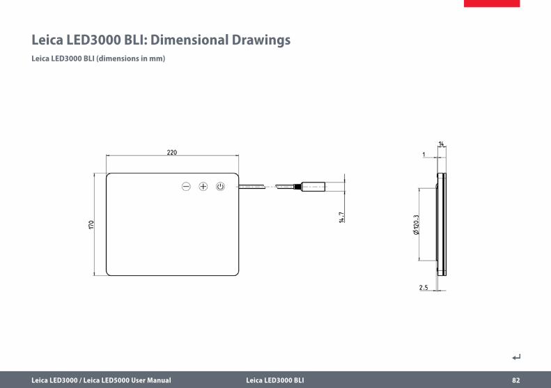
Leica LED3000 BLI: Dimensional DrawingsLeica LED3000 BLI (dimensions in mm)
Leica LED3000 / Leica LED5000 User Manual Leica LED5000 HDI 83
Leica LED5000 HDI
Leica LED3000 / Leica LED5000 User Manual Leica LED5000 HDI 84
The Leica LED5000 HDI (for “High Diffuse Illu-mination”) is a newly-designed, innovative high-output illuminator. Its soft light reduces reflection on highly reflective specimens and prevents stray light.
The Leica LED5000 HDI consists of a flexible plastic dome. It houses two independent LED rings that can be controlled individually.
It is controlled using either the integrated keypad or via the Leica Application Suite (LAS) or the Leica SmartTouch.
The Leica LED5000 HDI is installed on the objec-tive using a single screw. The working distance has been optimized for a height between 60 and 70 mm.
ConstraintsThe Leica LED5000 HDI can only be used with objectives that have an outer diameter of 80 mm.
The Leica LED5000 HDI has been optimized for the planapochromat 1× and planapochromat 0.63×.
Control via Leica Application Suite
The Leica LED5000 HDI illuminator has been supported since LAS version 3.6.
LAS enables you to create fully reproduc-ible illumination scenarios and automati-
cally toggle between them. For additional infor-mation, refer to the LAS online help.
About the Leica LED5000 HDI
Leica LED3000 / Leica LED5000 User Manual Leica LED5000 HDI 85
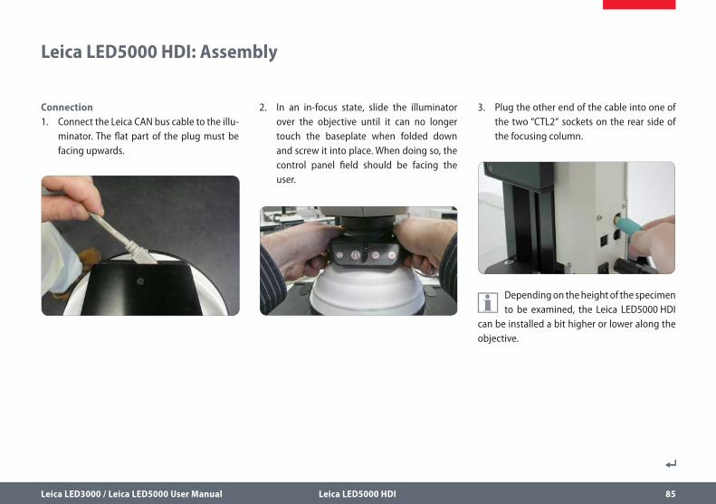
Connection1. Connect the Leica CAN bus cable to the illu-
minator. The flat part of the plug must be facing upwards.
2. In an in-focus state, slide the illuminator over the objective until it can no longer touch the baseplate when folded down and screw it into place. When doing so, the control panel field should be facing the user.
3. Plug the other end of the cable into one of the two “CTL2“ sockets on the rear side of the focusing column.
Depending on the height of the specimen to be examined, the Leica LED5000 HDI
can be installed a bit higher or lower along the objective.
Leica LED5000 HDI: Assembly
Leica LED3000 / Leica LED5000 User Manual Leica LED5000 HDI 86
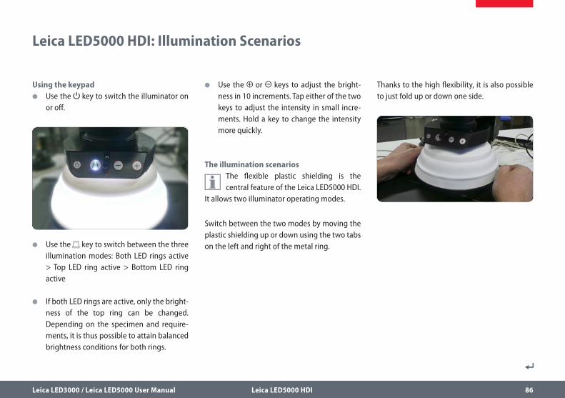
Using the keypad O Use the key to switch the illuminator on
or off.
O Use the key to switch between the three illumination modes: Both LED rings active > Top LED ring active > Bottom LED ring active
O If both LED rings are active, only the bright-ness of the top ring can be changed. Depending on the specimen and require-ments, it is thus possible to attain balanced brightness conditions for both rings.
O Use the or keys to adjust the bright-ness in 10 increments. Tap either of the two keys to adjust the intensity in small incre-ments. Hold a key to change the intensity more quickly.
The illumination scenarios
The flexible plastic shielding is the central feature of the Leica LED5000 HDI.
It allows two illuminator operating modes.
Switch between the two modes by moving the plastic shielding up or down using the two tabs on the left and right of the metal ring.
Thanks to the high flexibility, it is also possible to just fold up or down one side.
Leica LED5000 HDI: Illumination Scenarios
Leica LED3000 / Leica LED5000 User Manual Leica LED5000 HDI 87
Leica LED5000 HDI: Illumination Scenarios (Continued)
The use of flexible plastic eliminates “hard collisions” with specimens to a
large extent. For very sensitive specimens, however, even the weight of the illuminator itself can cause damage.
The Leica LED5000 HDI illuminator is not suitable for inspecting ESD-sensitive
assemblies, components or parts.
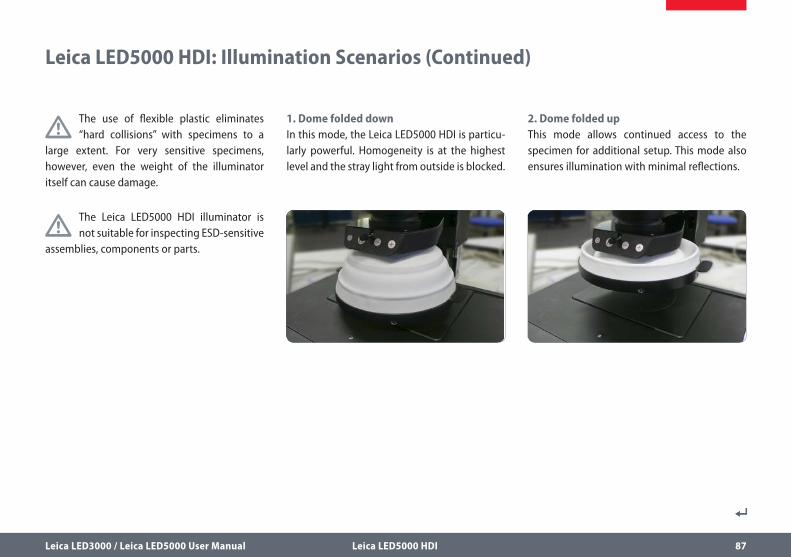
1. Dome folded downIn this mode, the Leica LED5000 HDI is particu-larly powerful. Homogeneity is at the highest level and the stray light from outside is blocked.
2. Dome folded upThis mode allows continued access to the specimen for additional setup. This mode also ensures illumination with minimal reflections.
Leica LED3000 / Leica LED5000 User Manual Leica LED5000 HDI 88
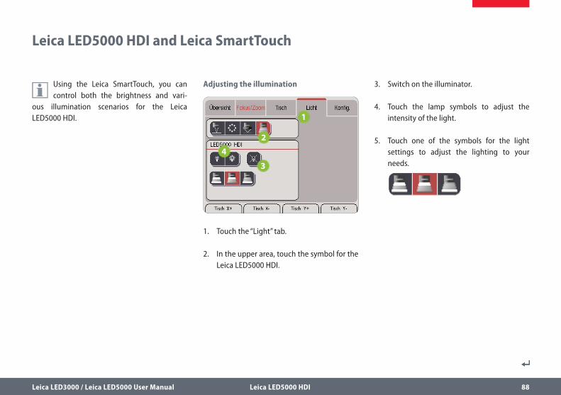
Leica LED5000 HDI and Leica SmartTouch
Using the Leica SmartTouch, you can control both the brightness and vari-
ous illumination scenarios for the Leica LED5000 HDI.
Adjusting the illumination
1. Touch the “Light” tab.
2. In the upper area, touch the symbol for the Leica LED5000 HDI.
3. Switch on the illuminator.
4. Touch the lamp symbols to adjust the intensity of the light.
5. Touch one of the symbols for the light settings to adjust the lighting to your needs.
Leica LED3000 / Leica LED5000 User Manual Leica LED5000 HDI 89
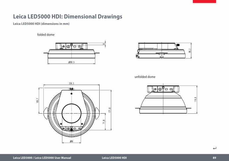
Leica LED5000 HDI: Dimensional DrawingsLeica LED5000 HDI (dimensions in mm)
folded dome
unfolded dome
Leica LED3000 / Leica LED5000 User Manual Leica LED3000 DI 90
Leica LED3000 DI
Leica LED3000 / Leica LED5000 User Manual Leica LED3000 DI 91
The Leica LED3000 DI (für “Diffuse Illumina-tion”) is an illuminator that generates a diffuse light. It consists of an illumination screen that reflects the light in different directions. The diffuse features of the light source can enable a shadow-free illumination of the products, which is a particular advantage for documenta-tion purposes.
Due to the flexible arm, the Leica LED3000 DI can easily be installed as an additional, mobile light source, for example, on a ring light illumi-nator. If needed, the Leica LED3000 DI can easily be positioned between the objective and the product. Its design ensures that accessibility to the product remains sufficient.
For higher-value tasks, it is recommend to use the Leica LED5000 HDI, which induces an even higher diffused light with minor shadowing.
It is controlled using either the integrated keypad on the flexible arm, via the Leica Appli-cation Suite (LAS) or the Leica SmartTouch.
About the Leica LED3000 DI
Leica LED3000 / Leica LED5000 User Manual Leica LED3000 DI 92
Leica LED3000 DI: Assembly
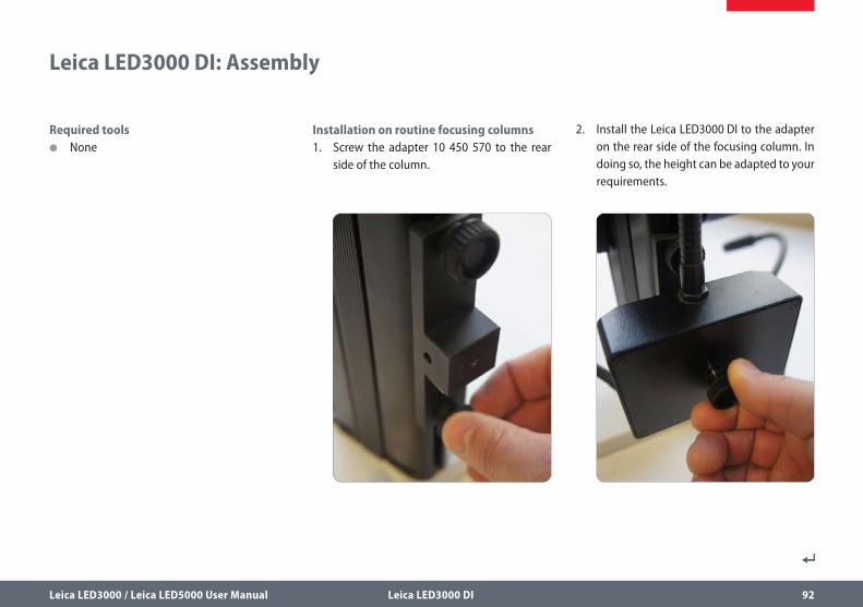
Required tools O None
Installation on routine focusing columns 1. Screw the adapter 10 450 570 to the rear
side of the column.
2. Install the Leica LED3000 DI to the adapter on the rear side of the focusing column. In doing so, the height can be adapted to your requirements.
Leica LED3000 / Leica LED5000 User Manual Leica LED3000 DI 93
Leica LED3000 DI: Assembly (Continued)
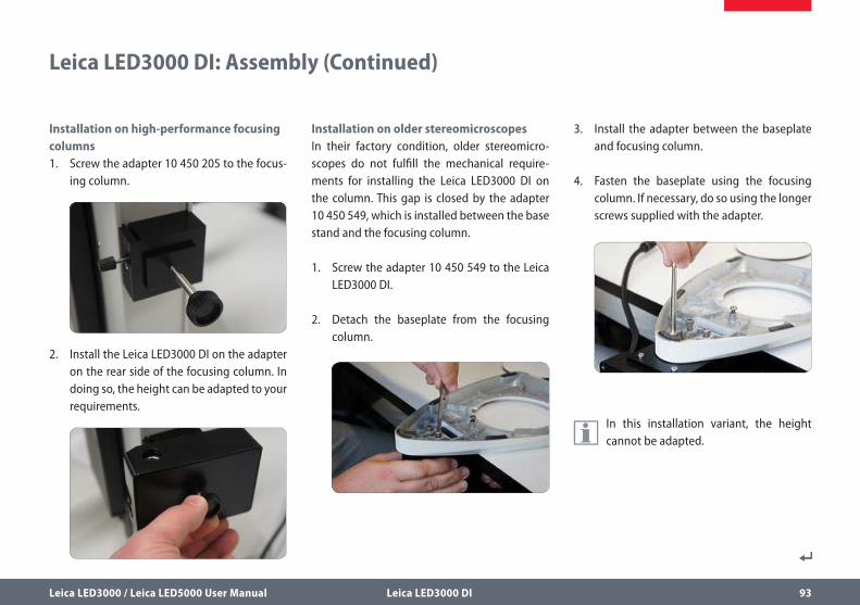
Installation on high-performance focusing columns 1. Screw the adapter 10 450 205 to the focus-
ing column.
2. Install the Leica LED3000 DI on the adapter on the rear side of the focusing column. In doing so, the height can be adapted to your requirements.
Installation on older stereomicroscopes In their factory condition, older stereomicro-scopes do not fulfill the mechanical require-ments for installing the Leica LED3000 DI on the column. This gap is closed by the adapter 10 450 549, which is installed between the base stand and the focusing column.
1. Screw the adapter 10 450 549 to the Leica LED3000 DI.
2. Detach the baseplate from the focusing column.
3. Install the adapter between the baseplate and focusing column.
4. Fasten the baseplate using the focusing column. If necessary, do so using the longer screws supplied with the adapter.
In this installation variant, the height cannot be adapted.
Leica LED3000 / Leica LED5000 User Manual Leica LED3000 DI 94
Leica LED3000 DI: Power Supply
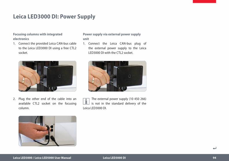
Focusing columns with integrated electronics 1. Connect the provided Leica CAN-bus cable
to the Leica LED3000 DI using a free CTL2 socket.
2. Plug the other end of the cable into an available CTL2 socket on the focusing column.
Power supply via external power supply unit 1. Connect the Leica CAN-bus plug of
the external power supply to the Leica LED3000 DI with the CTL2 socket.
The external power supply (10 450 266) is not in the standard delivery of the
Leica LED3000 DI.
Leica LED3000 / Leica LED5000 User Manual Leica LED3000 DI 95
Leica LED3000 DI: Use
Positioning of the illumination screen The position of the illumination screen of the Leica LED3000 DI can be individually positioned over the product due to the flexible gooseneck. When not using the illuminator, this can easily be swung to the side without removing it from the microscope.
Positioning of the keypad The flexible gooseneck allows you to move the keypad into any position desired. This makes handling of the system more ergonomic, while repetitive steps are also optimized by the more efficient movements.
Leica LED3000 / Leica LED5000 User Manual Leica LED3000 DI 96
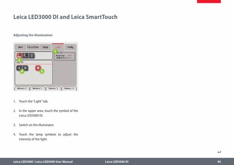
Leica LED3000 DI and Leica SmartTouch
Adjusting the illumination
1. Touch the “Light” tab.
2. In the upper area, touch the symbol of the Leica LED3000 DI.
3. Switch on the illuminator.
4. Touch the lamp symbols to adjust the intensity of the light.
Leica LED3000 / Leica LED5000 User Manual Leica LED3000 DI 97
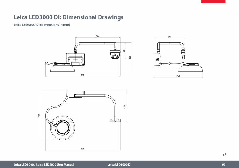
Leica LED3000 DI: Dimensional DrawingsLeica LED3000 DI (dimensions in mm)
Leica LED3000 / Leica LED5000 User Manual Leica LED3000 SLI / Leica LED5000 SLI 98
Leica LED3000 SLI / Leica LED5000 SLI
Leica LED3000 / Leica LED5000 User Manual Leica LED3000 SLI / Leica LED5000 SLI 99
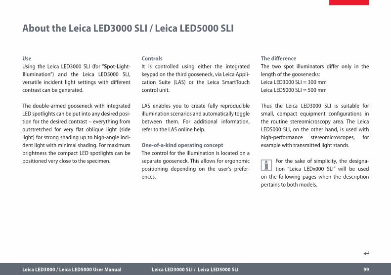
UseUsing the Leica LED3000 SLI (for “Spot-Light-Illumination”) and the Leica LED5000 SLI, versatile incident light settings with different contrast can be generated.
The double-armed gooseneck with integrated LED spotlights can be put into any desired posi-tion for the desired contrast – everything from outstretched for very flat oblique light (side light) for strong shading up to high-angle inci-dent light with minimal shading. For maximum brightness the compact LED spotlights can be positioned very close to the specimen.
ControlsIt is controlled using either the integrated keypad on the third gooseneck, via Leica Appli-cation Suite (LAS) or the Leica SmartTouch control unit.
LAS enables you to create fully reproducible illumination scenarios and automatically toggle between them. For additional information, refer to the LAS online help.
One-of-a-kind operating concept The control for the illumination is located on a separate gooseneck. This allows for ergonomic positioning depending on the user‘s prefer-ences.
The differenceThe two spot illuminators differ only in the length of the goosenecks:Leica LED3000 SLI = 300 mmLeica LED5000 SLI = 500 mm
Thus the Leica LED3000 SLI is suitable for small, compact equipment configurations in the routine stereomicroscopy area. The Leica LED5000 SLI, on the other hand, is used with high-performance stereomicroscopes, for example with transmitted light stands.
For the sake of simplicity, the designa-tion “Leica LEDx000 SLI” will be used
on the following pages when the description pertains to both models.
About the Leica LED3000 SLI / Leica LED5000 SLI
Leica LED3000 / Leica LED5000 User Manual Leica LED3000 SLI / Leica LED5000 SLI 100
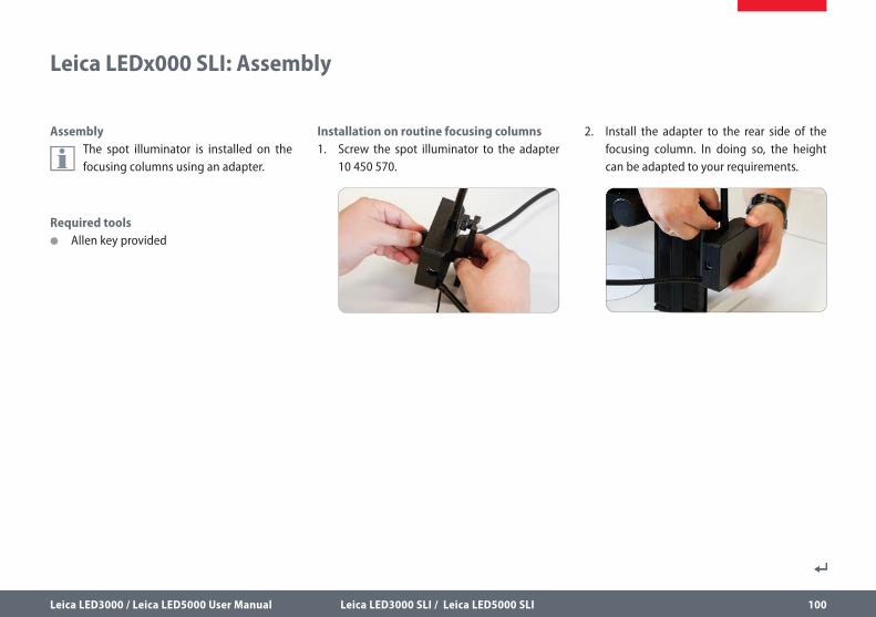
Assembly
The spot illuminator is installed on the focusing columns using an adapter.
Required tools O Allen key provided
Installation on routine focusing columns1. Screw the spot illuminator to the adapter
10 450 570.
2. Install the adapter to the rear side of the focusing column. In doing so, the height can be adapted to your requirements.
Leica LEDx000 SLI: Assembly
Leica LED3000 / Leica LED5000 User Manual Leica LED3000 SLI / Leica LED5000 SLI 101
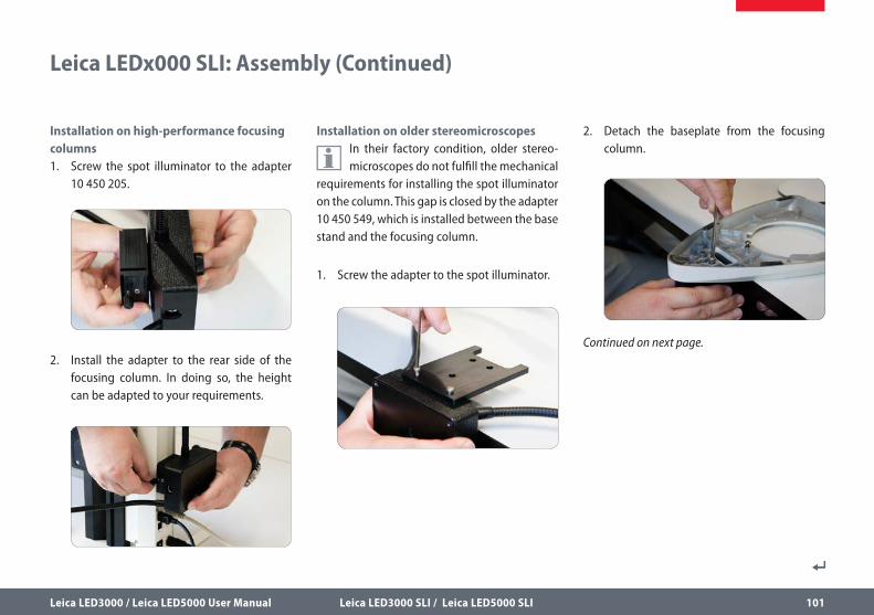
Leica LEDx000 SLI: Assembly (Continued)
2. Detach the baseplate from the focusing column.
Continued on next page.
Installation on older stereomicroscopes
In their factory condition, older stereo-microscopes do not fulfill the mechanical
requirements for installing the spot illuminator on the column. This gap is closed by the adapter 10 450 549, which is installed between the base stand and the focusing column.
1. Screw the adapter to the spot illuminator.
Installation on high-performance focusing columns1. Screw the spot illuminator to the adapter
10 450 205.
2. Install the adapter to the rear side of the focusing column. In doing so, the height can be adapted to your requirements.
Leica LED3000 / Leica LED5000 User Manual Leica LED3000 SLI / Leica LED5000 SLI 102
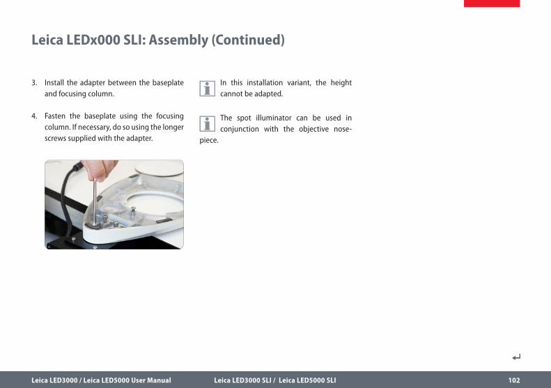
In this installation variant, the height cannot be adapted.
The spot illuminator can be used in conjunction with the objective nose-
piece.
Leica LEDx000 SLI: Assembly (Continued)
3. Install the adapter between the baseplate and focusing column.
4. Fasten the baseplate using the focusing column. If necessary, do so using the longer screws supplied with the adapter.
Leica LED3000 / Leica LED5000 User Manual Leica LED3000 SLI / Leica LED5000 SLI 103
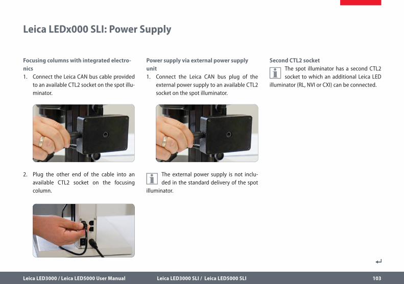
Focusing columns with integrated electro-nics1. Connect the Leica CAN bus cable provided
to an available CTL2 socket on the spot illu-minator.
2. Plug the other end of the cable into an available CTL2 socket on the focusing column.
Power supply via external power supply unit1. Connect the Leica CAN bus plug of the
external power supply to an available CTL2 socket on the spot illuminator.
The external power supply is not inclu-ded in the standard delivery of the spot
illuminator.
Second CTL2 socket
The spot illuminator has a second CTL2 socket to which an additional Leica LED
illuminator (RL, NVI or CXI) can be connected.
Leica LEDx000 SLI: Power Supply
Leica LED3000 / Leica LED5000 User Manual Leica LED3000 SLI / Leica LED5000 SLI 104
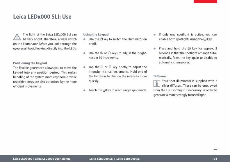
The light of the Leica LEDx000 SLI can be very bright. Therefore, always switch
on the illuminator before you look through the eyepieces! Avoid looking directly into the LEDs.
Positioning the keypadThe flexible gooseneck allows you to move the keypad into any position desired. This makes handling of the system more ergonomic, while repetitive steps are also optimized by the more efficient movements.
Using the keypad O Use the key to switch the illuminator on
or off.
O Use the or keys to adjust the bright-ness in 10 increments.
O Tap the or key briefly to adjust the intensity in small increments. Hold one of the two keys to change the intensity more quickly.
O Touch the key to reach single spot mode.
O If only one spotlight is active, you can enable both spotlights using the key.
O Press and hold the key for approx. 2 seconds so that the spotlights change auto-matically. Press the key again to disable to automatic changeover.
Diffusers
Your spot illuminator is supplied with 2 silver diffusers. These can be unscrewed
from the LED spotlight if necessary in order to generate a more strongly focused light.
Leica LEDx000 SLI: Use

Leica LED3000 / Leica LED5000 User Manual Leica LED3000 SLI / Leica LED5000 SLI 105
Using the Leica SmartTouch control unit, you can control both the brightness and
various illumination scenarios for the spot illu-minator.
Adjusting the illumination
1. Touch the “Light” tab.
2. In the upper area, touch the symbol for the Leica LED SLI.
3. Switch on the illuminator.
4. Touch the lamp symbols to adjust the intensity of the light.
5. Touch one of the symbols for the illumina-tion scenarios to adjust the lighting to your needs.
Leica LEDx000 SLI: Use with Leica SmartTouch
210
90
90
210
21
0
172
248
214
331
414
331
414
90
Leica LED3000 / Leica LED5000 User Manual Leica LED3000 SLI / Leica LED5000 SLI 106
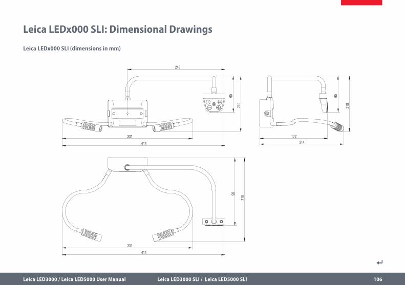
Leica LEDx000 SLI: Dimensional Drawings
Leica LEDx000 SLI (dimensions in mm)
www.leica-microsystems.com
10IDA26060EN ∙ Copyright © by Leica Microsystems (Schweiz) AG, CH-9435 Heerbrugg,
2014. Subject to change. LEICA and the Leica Logo are registered trademarks of
Leica Microsystems IR GmbH.
The statement by Ernst Leitz in 1907, “With the User, For the User,” describes the fruitful collaboration with end users and driving force of
innovation at Leica Microsystems. We have developed five brand values to live up to this tradition: Pioneering, High-end Quality, Team Spirit, Dedication to Science, and Continuous Improvement. For us, living up to these values means: Living up to Life.
INDUSTRY DIVISION
The Leica Microsystems Industry Division’s focus is to support customers’ pursuit of the highest quality end result. Leica Microsystems provide the best and most innovative imaging systems to see, measure, and analyze the microstructures in routine and research industrial applications, materials science, quality control, forensic science investigation, and educational applications.
Leica Microsystems – an international company with an experienced worldwide customer service network.
Active worldwide Tel. Fax
Australia ∙ North Ryde +61 2 8870 3500 2 9878 1055
Austria ∙ Vienna +43 1 486 80 50 0 1 486 80 50 30
Belgium ∙ Diegem +32 2 790 98 50 2 790 98 68
Canada ∙ Concord/Ontario +1 800 248 0123 847 405 0164
Denmark ∙ Ballerup +45 4454 0101 4454 0111
France ∙ Nanterre Cedex +33 811 000 664 1 56 05 23 23
Germany ∙ Wetzlar +49 64 41 29 40 00 64 41 29 41 55
Italy ∙ Milan +39 02 574 861 02 574 03392
Japan ∙ Tokyo +81 3 5421 2800 3 5421 2896
Korea ∙ Seoul +82 2 514 65 43 2 514 65 48
Netherlands ∙ Rijswijk +31 70 4132 100 70 4132 109
People’s Rep. of China ∙ Hong Kong +852 2564 6699 2564 4163
∙ Shanghai +86 21 6039 6000 21 6387 6698
Portugal ∙ Lisbon +351 21 388 9112 21 385 4668
Singapore +65 6779 7823 6773 0628
Spain ∙ Barcelona +34 93 494 95 30 93 494 95 32
Sweden ∙ Kista +46 8 625 45 45 8 625 45 10
Switzerland ∙ Heerbrugg +41 71 726 34 34 71 726 34 44
United Kingdom ∙ Milton Keynes +44 800 298 2344 1908 246312
USA ∙ Buffalo Grove/lllinois +1 800 248 0123 847 405 0164