leena, mr. subham gandhi and mr. jitender khurana ...iret.co.in/docs/ijntec/volume 1/issue1/6....
TRANSCRIPT
Leena, Mr. Subham Gandhi and Mr. Jitender Khurana 21
International Journal of New Trends in Electronics and Communication (IJNTEC)…………………………………..Vol.1, Issue. 1, Aug. 2013
Implementing (7, 4) Hamming Code using CPLDon VHDL
Leena, Mr. Subham Gandhi and Mr. Jitender Khurana
Abstract: During communication when data is transmitted fromsender to receiver then an error occurs. So there are varioustechnique used to detect and correct error. One of them isHamming Code which we use in this paper. Using HammingCode is this paper has advantage that we are implementing thetechnique in VHDL software.. In order to do that the proposedmethod uses a complex programmable logic device (CPLD).It isknown that CPLD provides quick implementation and fasthardware verification. It gives facilities of reconfiguring thedesign construct unlimited number of times. Hence, an attemptis made to implement the Hamming Code for detecting andcorrecting errors.
Index Terms:-Complex Programmable Logic Device (CPLD),Very High Speed Integrated Circuit Hardware Description language(VHDL), Xilinx, redundancy.
I. INTRODUCTIONCoding theory is concerned with reliability ofcommunication over noisy channels. Error correcting codesare used in a wide range of communication systems fromdeep space communication, to quality of sound in compactdisksand wireless phones. In computers, data of any kind isstored and processed as binary digits (or bits for short). A bitis a 0 or a 1. Every letter has an ASCII code. For example,the ASCII code of the letter ‘A’ is 01000001. Typically,data consists of billions of bits. Digital data is transmittedover a channel (which could be a wire, network, space, airetc.), And there is often noise in the channel. The noise maydistort the messages to be sent. Therefore, what the receiverreceives may not be the same as what the sender sends. Thegoal of coding theory is to improve the reliability of digitalcommunication by devising methods that enable the receiverto decide whether there have been errors during thetransmission (error detection), and if there are, to possiblyrecover the original message (error correction).[1]
A. ERRORError simply means that while transmitting data bits theremay be change of bits either from ‘0 to 1’ or from ‘1 to0’.This change may occur due to external interference orfrom noise. There are two types of errors.Single error in which one bit is change.Burst error in which more than one bits are changed.There are various error detection and correction techniquessuch as CRC, Parity check,LRC, VRC Hamming Code.Hamming Code is the better way to detect and correct singleerror which was given by R.W Hamming in 1950[2].
Leena is Mtech Student, Mr. Subham Gandhi and Mr. Jitender Khurana areworking as Associate Professor, Deptt. Of ECE, SBMN Engg.College,AsthalBohar,Rohtak, Emails: [email protected],[email protected], [email protected]
B. HAMMING CODEHammings development [Ham] is a very direct constructionof a code that permits correcting single-bit errors. Heassumes that the data to be transmitted consists of a certainnumber of information bits, and he adds to these a number ofcheck bits ‘p’ such that if a block is received that has atmost one bit in error, then ‘p’ identifies the bit that is in error(which may be one of the check bits). Specifically, inHamming code ‘p’ is interpreted as an integer which is 0 ifno error occurred, and otherwise is the 1-origined index ofthe bit that is in error. Let ‘k’ be the number of informationbits, and ‘m ’the number of check bits used. Because themcheck bits must check themselves as well as the informationbits, the value of ‘p’ ,interpreted as an integer, must rangefrom 0 to which is distinct values. Because ‘m’ bits candistinguish cases, we must have
2m ≥ m+k+1
This is known as the Hamming rule [3].
This project attempts to correct and detect the errors usingVHDL. As when we transmit any signal its bits can bechanged due to external interference so the signal getcorrupted . Hamming codes are used to correct the eroor andwhen it is implemented in VHDL. Being an electronicsystem it is reliable, compact and maintenance free. VHDLmakes the system versatile as the on off times can be easilyvaried by changing the delay loops through software. [3]
II. CPLD
Complex Programmable Logic Device (CPLD) AComplex Programmable Logic Device (CPLD) is aprogrammable logic device with complexity between that ofPALs and FPGAs, and architectural features of both. Themaximum clock frequency is 20 MHz and hence it is fasterthan microcontroller. The use of CPLDs (FieldProgrammable Gate Arrays) and configurable processors isan interesting new phenomenon in embedded development isa combination of a fully programmable AND/OR array and abank of macro cells. The AND/OR array is reprogrammableand can perform a multitude of logic functions.. ComplexProgrammable Logic Devices (CPLDs) are exactly what theyclaim to be. These are designed to appear just like a largenumber of PALs in a single chip, connected to each otherthrough a cross point switch. They use the same developmenttools and programmers, and are based on the sametechnologies, but they can handle much more complexlogic and more of it.

Leena, Mr. Subham Gandhi and Mr. Jitender Khurana 22
International Journal of New Trends in Electronics and Communication (IJNTEC)…………………………………..Vol.1, Issue. 1, Aug. 2013
Xilinx is a vendor of CPLD products and manufactures afamily known as the XC9500. In this project Xilinx ISE8.1version is used. CPLDs enable ease of design, lowerdevelopment costs, and more product revenue for yourmoney, and the opportunity to speed your products to market.Ease of Design: CPLDs offer the simplest way to implementa design. Once a design has been described, by schematicand/or HDL entry, you simply use CPLD development toolsto optimize, fit, and simulate the design. The developmenttools create a file that is used to customize (that is, program)a standard off-the-shelf CPLD with the desired functionality.This provides an instant hardware prototype and allows thedebugging process to begin. If modifications are needed, youcan enter design changes into the CPLD development tool,and re-implement and test the design immediately.
Fig1. CPLD kit
III. IMPLEMENTING DESIGN ON CPLDThe process of implementing a design on an CPLD can bebroken down into several stages, loosely definable as designentry or capture, synthesis, and place and route.
Fig 2. Design Flow for CPLD
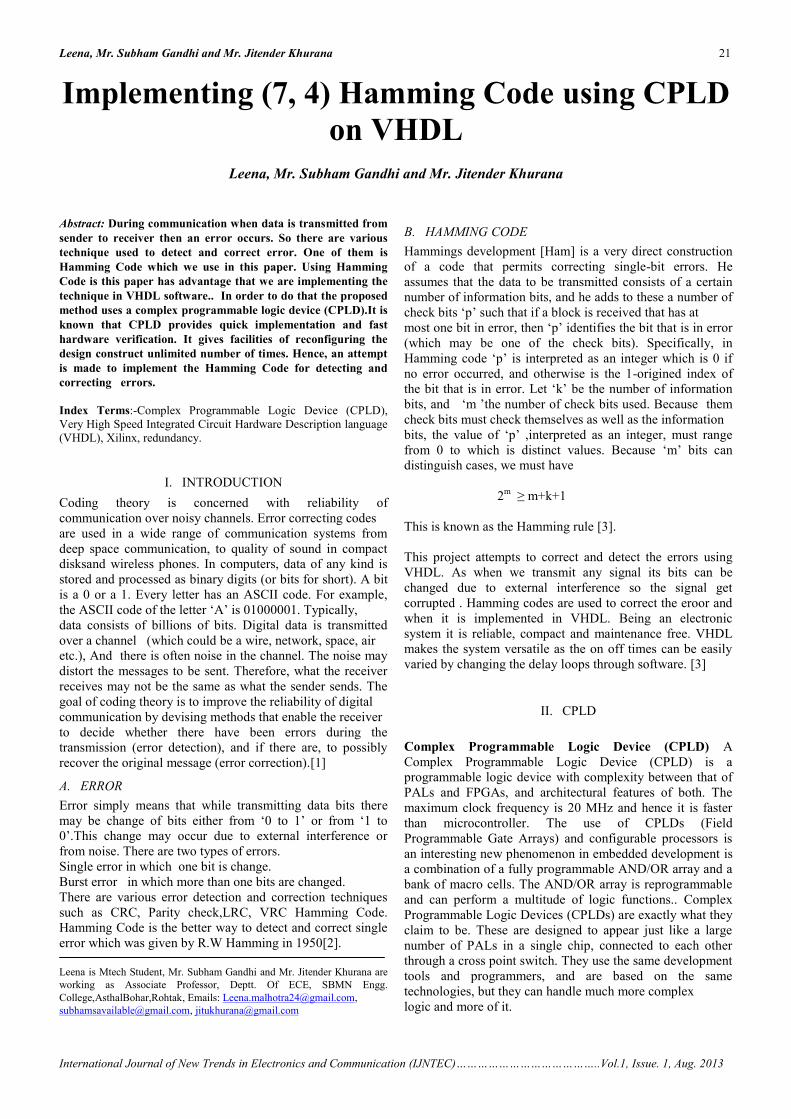
A. RTL Simulation:After design entry, the design is simulated at the register-transfer level (RTL). This is the first of several simulationstages, because the design must be simulated at successivelevels of abstraction as it moves down the chain towardphysical implementation on the CPLD itself. RTL simulationoffers the highest performance in terms of speed.
B. Synthesis ProcessThe next level in the design process is synthesis.. RTL is sentthrough a synthesis tool that produces a netlist of hardwarecomponents needed to actually build the system. After thesynthesis tool the net list is used to desing the logicnetwork.Verification at this level consist of simulations toensure that logic is correct.
C. Gate Level Simulation Process:Simulation can be used to help optimize the design and refinethe logic, though designers need to be careful not to use it inthe undisciplined software-style code-and-fix mode.After design synthesis, but before physical implementation,functional simulation is used to help verify the design. Thegoal of functional simulation is to ensure that the logic of thedesign does what you want it to do, per the specification, andthat it produces the correct results.
Leena, Mr. Subham Gandhi and Mr. Jitender Khurana 22
International Journal of New Trends in Electronics and Communication (IJNTEC)…………………………………..Vol.1, Issue. 1, Aug. 2013
Xilinx is a vendor of CPLD products and manufactures afamily known as the XC9500. In this project Xilinx ISE8.1version is used. CPLDs enable ease of design, lowerdevelopment costs, and more product revenue for yourmoney, and the opportunity to speed your products to market.Ease of Design: CPLDs offer the simplest way to implementa design. Once a design has been described, by schematicand/or HDL entry, you simply use CPLD development toolsto optimize, fit, and simulate the design. The developmenttools create a file that is used to customize (that is, program)a standard off-the-shelf CPLD with the desired functionality.This provides an instant hardware prototype and allows thedebugging process to begin. If modifications are needed, youcan enter design changes into the CPLD development tool,and re-implement and test the design immediately.
Fig1. CPLD kit
III. IMPLEMENTING DESIGN ON CPLDThe process of implementing a design on an CPLD can bebroken down into several stages, loosely definable as designentry or capture, synthesis, and place and route.
Fig 2. Design Flow for CPLD
A. RTL Simulation:After design entry, the design is simulated at the register-transfer level (RTL). This is the first of several simulationstages, because the design must be simulated at successivelevels of abstraction as it moves down the chain towardphysical implementation on the CPLD itself. RTL simulationoffers the highest performance in terms of speed.
B. Synthesis ProcessThe next level in the design process is synthesis.. RTL is sentthrough a synthesis tool that produces a netlist of hardwarecomponents needed to actually build the system. After thesynthesis tool the net list is used to desing the logicnetwork.Verification at this level consist of simulations toensure that logic is correct.
C. Gate Level Simulation Process:Simulation can be used to help optimize the design and refinethe logic, though designers need to be careful not to use it inthe undisciplined software-style code-and-fix mode.After design synthesis, but before physical implementation,functional simulation is used to help verify the design. Thegoal of functional simulation is to ensure that the logic of thedesign does what you want it to do, per the specification, andthat it produces the correct results.
Leena, Mr. Subham Gandhi and Mr. Jitender Khurana 23
International Journal of New Trends in Electronics and Communication (IJNTEC)…………………………………..Vol.1, Issue. 1, Aug. 2013
Fig 3. Final Gate Level Simulation Stages
IV. VHDLVHDL (Very high speed integrated circuit HardwareDescription Language) became IEEE standard 1076 in 1987.It was updated in 1993 and is known today as "IEEEstandard 1076 1993.Another language of HDL is VERILOG.It is used in electronic design automation to describe digitaland mixed signal systems such as field-programmable gatearray.
IV. IMPLEMENTATION OF HAMMING CODE ONCPLD USING VHDL
A. ENCODING OF HAMMING CODENow, the design of Hamming Code (7, 4) is to be done onCPLD kit using VHDL. (7,4) means that there are 4-data bitsand and we need 3-parity bits to send along with these databits to make it 7-bit codeword. Even parity is used in.Databits are d2,d4,d5,d6; and parity bits are p1,p2,p3.Where d0 is Ist bit which is given as: d0=20=1
D1 is 2nd bit and is given as : d1=21=2D3 is 4th bit and is given as : d3=22=4
D0= 0 0 0 1
D1= 0 0 1 0
D2= 0 0 1 1
D3= 0 1 0 0
D4= 0 1 0 1
D5= 0 1 1 0
D6= 0 1 1 1
P1=d0, d2, d4, d6
P2=d1 ,d2 ,d4,d6;
P3=d3, d4,d5,d6;
0 0 0 P3 1 P2 P1
D6 D5 D4 D3 D2 D1 D0
Where 0001 is data and p1,p2, p3 are parity bits which takethe position 2m where m =0,1,2,3---------------so on . whichare check bits.
For calculating p1:-Count the number of 1’s in d1,d3,d5,d7 ,if there are evennumber of 1 then p1=0 otherwise it is 1.Therefore, p1=1
For calculating p2:-Count the number of 1’s in d2,d3,d6,d7 ,if there are evennumber of 1 then p1=0 otherwise it is 1.Therefore, p2=1
For calculating p3:-Count the number of 1’s in d4,d5,d6,d7 ,if there are evennumber of 1 then p1=0 otherwise it is 1.Therefore, p3=1
Therefore the 7-bit codeword is
0 0 0 0 1 1 1
D6 D5 D4 D3 D2 D1 D0
Leena, Mr. Subham Gandhi and Mr. Jitender Khurana 24
International Journal of New Trends in Electronics and Communication (IJNTEC)…………………………………..Vol.1, Issue. 1, Aug. 2013
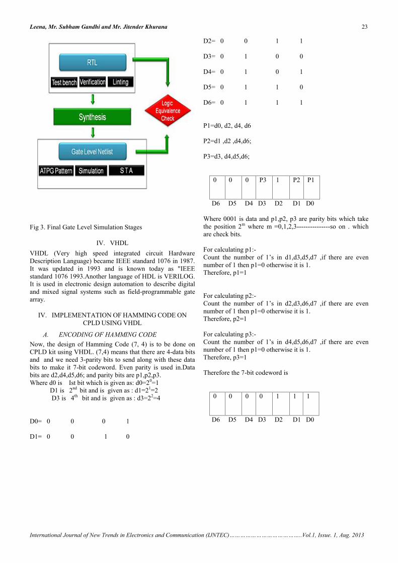
Fig 4. Transmitted Data
Fig5. 7-bit data
B. DECODING OF HAMMING CODE
When this 7-bit codeword is sent then during transmissionerror occurs which change the bits from 1 to 0 or 0 to 1.
7 – bit codeword at Transmitter
0 0 0 0 1 1 1
D6 D5 D4 D3 D2 D1 D0
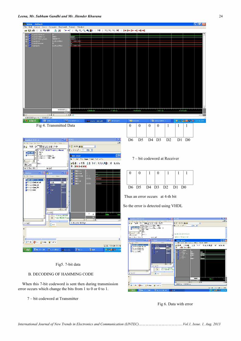
7 – bit codeword at Receiver
0 0 1 0 1 1 1
D6 D5 D4 D3 D2 D1 D0
Thus an error occurs at 4-th bit
So the error is detected using VHDL
Fig 6. Data with error
Leena, Mr. Subham Gandhi and Mr. Jitender Khurana 25
International Journal of New Trends in Electronics and Communication (IJNTEC)…………………………………..Vol.1, Issue. 1, Aug. 2013
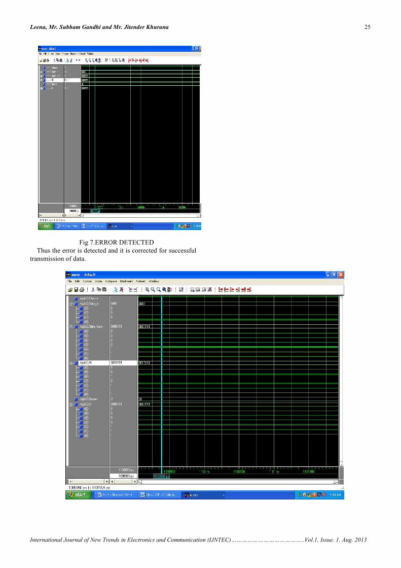
Fig 7.ERROR DETECTEDThus the error is detected and it is corrected for successful
transmission of data.
Leena, Mr. Subham Gandhi and Mr. Jitender Khurana 26
International Journal of New Trends in Electronics and Communication (IJNTEC)…………………………………..Vol.1, Issue. 1, Aug. 2013
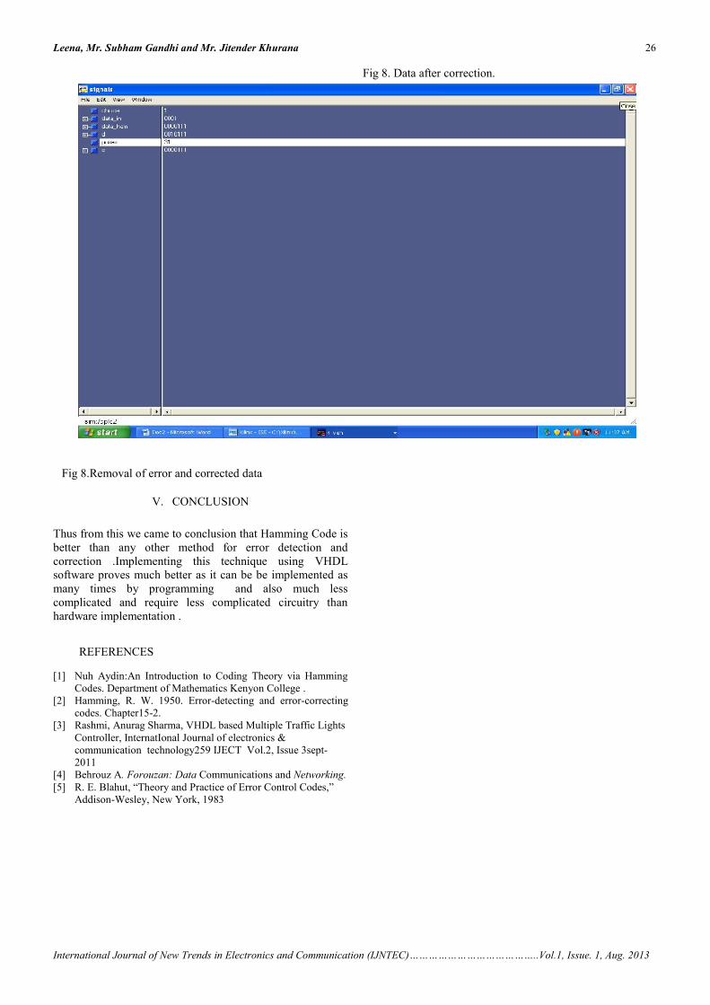
Fig 8. Data after correction.
Fig 8.Removal of error and corrected data
V. CONCLUSION
Thus from this we came to conclusion that Hamming Code isbetter than any other method for error detection andcorrection .Implementing this technique using VHDLsoftware proves much better as it can be be implemented asmany times by programming and also much lesscomplicated and require less complicated circuitry thanhardware implementation .
REFERENCES
[1] Nuh Aydin:An Introduction to Coding Theory via HammingCodes. Department of Mathematics Kenyon College .
[2] Hamming, R. W. 1950. Error-detecting and error-correctingcodes. Chapter15-2.
[3] Rashmi, Anurag Sharma, VHDL based Multiple Traffic LightsController, InternatIonal Journal of electronics &communication technology259 IJECT Vol.2, Issue 3sept-2011
[4] Behrouz A. Forouzan: Data Communications and Networking.[5] R. E. Blahut, “Theory and Practice of Error Control Codes,”
Addison-Wesley, New York, 1983