lecture 5 - basic resistive electrical circuits - ipfwlin/ecet211/sumii-2014/lecturenotes/lecture...
TRANSCRIPT
7/10/2014
1
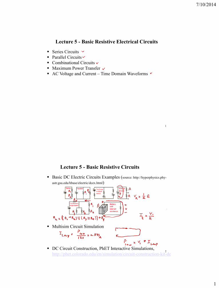
Lecture 5 - Basic Resistive Electrical Circuits
Series Circuits
Parallel Circuits
Combinational Circuits
Maximum Power Transfer
AC Voltage and Current – Time Domain Waveforms
1
Lecture 5 - Basic Resistive Circuits
Basic DC Electric Circuits Examples (source: http://hyperphysics.phy-
astr.gsu.edu/hbase/electric/dcex.html)
Multisim Circuit Simulation
DC Circuit Construction, PhET Interactive Simulations,
http://phet.colorado.edu/en/simulation/circuit-construction-kit-dc2
7/10/2014
2
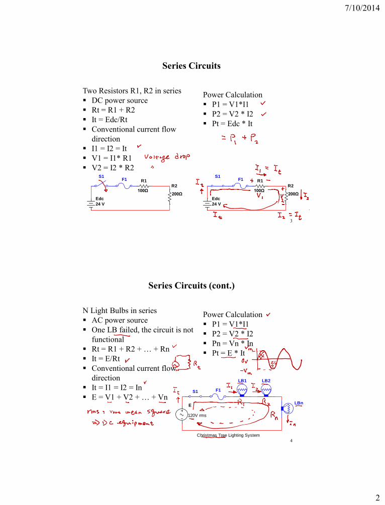
Series Circuits
Two Resistors R1, R2 in series
DC power source
Rt = R1 + R2
It = Edc/Rt
Conventional current flow
direction
I1 = I2 = It
V1 = I1* R1
V2 = I2 * R2
3
R1
100ΩR2
200ΩEdc
24 V
S1F1 R1
100ΩR2
200ΩEdc
24 V
S1F1
Power Calculation
P1 = V1*I1
P2 = V2 * I2
Pt = Edc * It
Series Circuits (cont.)
N Light Bulbs in series
AC power source
One LB failed, the circuit is not
functional
Rt = R1 + R2 + … + Rn
It = E/Rt
Conventional current flow
direction
It = I1 = I2 = In
E = V1 + V2 + … + Vn
4
Power Calculation
P1 = V1*I1
P2 = V2 * I2
Pn = Vn * In
Pt = E * It
E
F1S1
LB1 LB2
LBn
120V rms
Christmas Tree Lighting System
7/10/2014
3
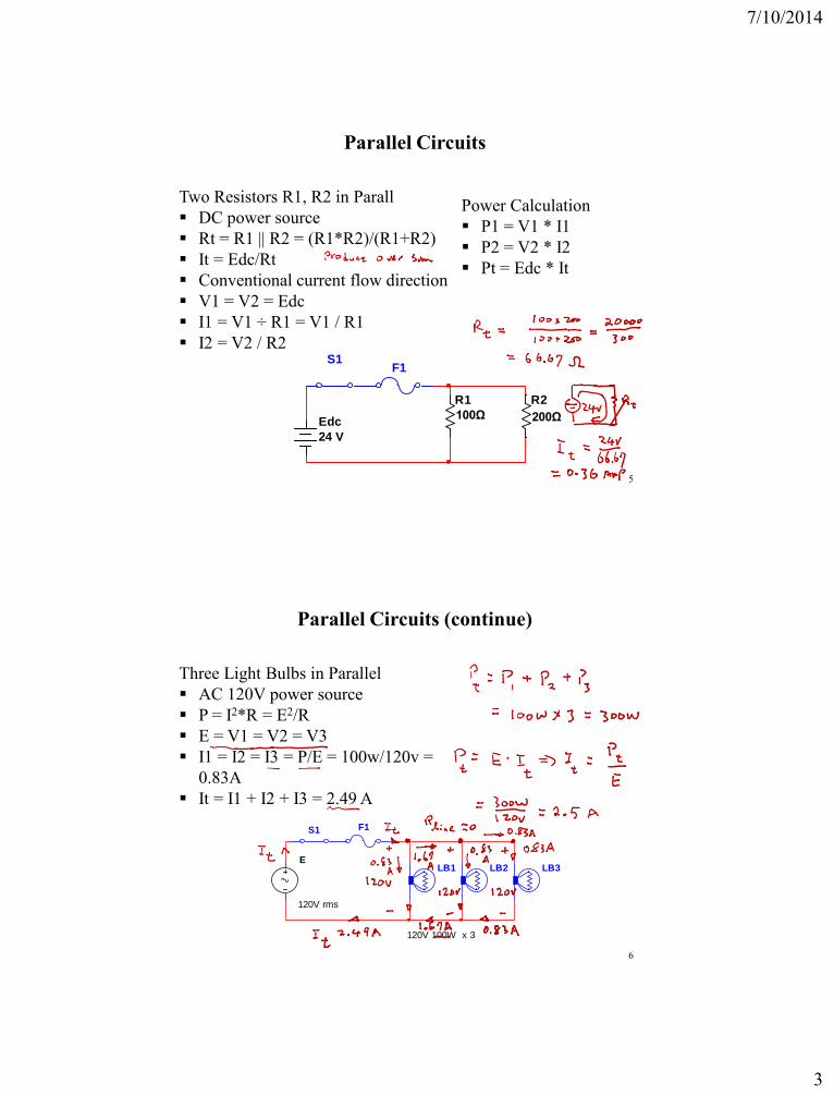
Parallel Circuits
Two Resistors R1, R2 in Parall
DC power source
Rt = R1 || R2 = (R1*R2)/(R1+R2)
It = Edc/Rt
Conventional current flow direction
V1 = V2 = Edc
I1 = V1 ÷ R1 = V1 / R1
I2 = V2 / R2
5
Power Calculation
P1 = V1 * I1
P2 = V2 * I2
Pt = Edc * It
R1
100Ω
R2
200ΩEdc
24 V
S1F1
Parallel Circuits (continue)
Three Light Bulbs in Parallel
AC 120V power source
P = I2*R = E2/R
E = V1 = V2 = V3
I1 = I2 = I3 = P/E = 100w/120v =
0.83A
It = I1 + I2 + I3 = 2.49 A
6
E
F1S1
LB1 LB2 LB3
120V 100W x 3
120V rms
7/10/2014
4
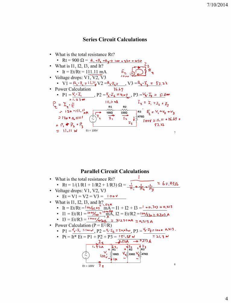
Series Circuit Calculations
• What is the total resistance Rt?
• Rt = 900 Ω = ______________________
• What is I1, I2, I3, and It?
• It = Et/Rt = 111.11 mA
• Voltage drops: V1, V2, V3
• V1 = _________, V2 = _______, V3 = _________
• Power Calculation
• P1 = _________, P2 = __________, P3 = _________
7
R1
100Ω
R2
330Ω R3
470Ω
Et = 100V
Parallel Circuit Calculations
• What is the total resistance Rt?
• Rt = 1/(1/R1 + 1/R2 + 1/R3) Ω = ______________________
• Voltage drops: V1, V2, V3
• Et = V1 = V2 = V3 = _________
• What is I1, I2, I3, and It?
• It = Et/Rt = _______ mA = I1 + I2 + I3 = __________
• I1 = Et/R1 = _______ mA, I2 = Et/R2 = ___________
• I3 = Et/R3 =_____________
• Power Calculation (P = E2/R)
• P1 = _________, P2 = __________, P3 = _________
• Pt = It* Et = P1 + P2 + P3 = ____________
8
R1
100Ω
R2
330Ω
R3
470Ω
Et = 100V
7/10/2014
5
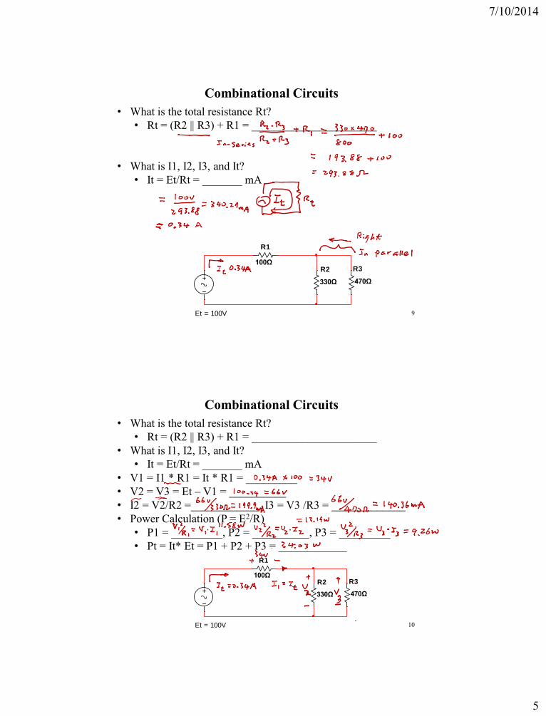
Combinational Circuits
• What is the total resistance Rt?
• Rt = (R2 || R3) + R1 = ______________________
• What is I1, I2, I3, and It?
• It = Et/Rt = _______ mA
9
R1
100ΩR2
330Ω
R3
470Ω
Et = 100V
Combinational Circuits
• What is the total resistance Rt?
• Rt = (R2 || R3) + R1 = ______________________
• What is I1, I2, I3, and It?
• It = Et/Rt = _______ mA
• V1 = I1 * R1 = It * R1 = _________
• V2 = V3 = Et – V1 = __________
• I2 = V2/R2 =____________, I3 = V3 /R3 = _____________
• Power Calculation (P = E2/R)
• P1 = _________, P2 = __________, P3 = _________
• Pt = It* Et = P1 + P2 + P3 = ____________
10
R1
100ΩR2
330Ω
R3
470Ω
Et = 100V
7/10/2014
6
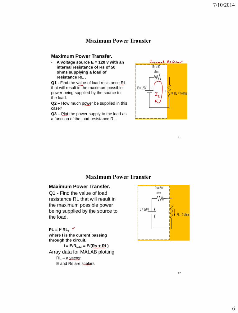
Maximum Power Transfer
Maximum Power Transfer. • A voltage source E = 120 v with an
internal resistance of Rs of 50
ohms supplying a load of
resistance RL .
Q1 - Find the value of load resistance RL
that will result in the maximum possible
power being supplied by the source to
the load.
Q2 – How much power be supplied in this
case?
Q3 – Plot the power supply to the load as
a function of the load resistance RL.
11
RL = ? ohms
Rs = 50
ohm
E = 120VI
Maximum Power Transfer
Maximum Power Transfer.
Q1 - Find the value of load
resistance RL that will result in
the maximum possible power
being supplied by the source to
the load.
PL = I2 RL,
where I is the current passing
through the circuit.
I = E/Rtotal = E/(Rs + RL)
Array data for MALAB plottingRL – a vector
E and Rs are scalars
12
RL = ? ohms
Rs = 50
ohm
E = 120VI
7/10/2014
7
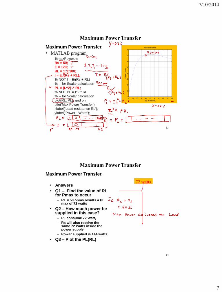
Maximum Power Transfer
Maximum Power Transfer.
• MATLAB program
13
0 10 20 30 40 50 60 70 80 90 1000
10
20
30
40
50
60
70
80Max Power Transfer
Load resistance RL
Pow
er
- W
att
s
%maxPower.m
Rs = 50;
E = 120;
RL = 1:1:100;
I = E./(Rs + RL);
% NOT I = E/(Rs + RL)
% -- for Scalar calculation
PL = (I.^2) .* RL;
% NOT PL = I^2 * RL
% -- for Scalar calculation
plot(RL, PL), grid on
title('Max Power Transfer');
xlabel('Load resistance RL');
ylabel('Power - Watts');
Maximum Power Transfer
Maximum Power Transfer.
14
• Answers
• Q1 – Find the value of RL for Pmax to occur– RL = 50 ohms results a PL
max of 72 watts
• Q2 – How much power be supplied in this case?– PL consume 72 Watt,
– Rs will also receive the same 72 Watts inside the power supply
– Power supplied is 144 watts
• Q3 – Plot the PL(RL)
72 watts
7/10/2014
8
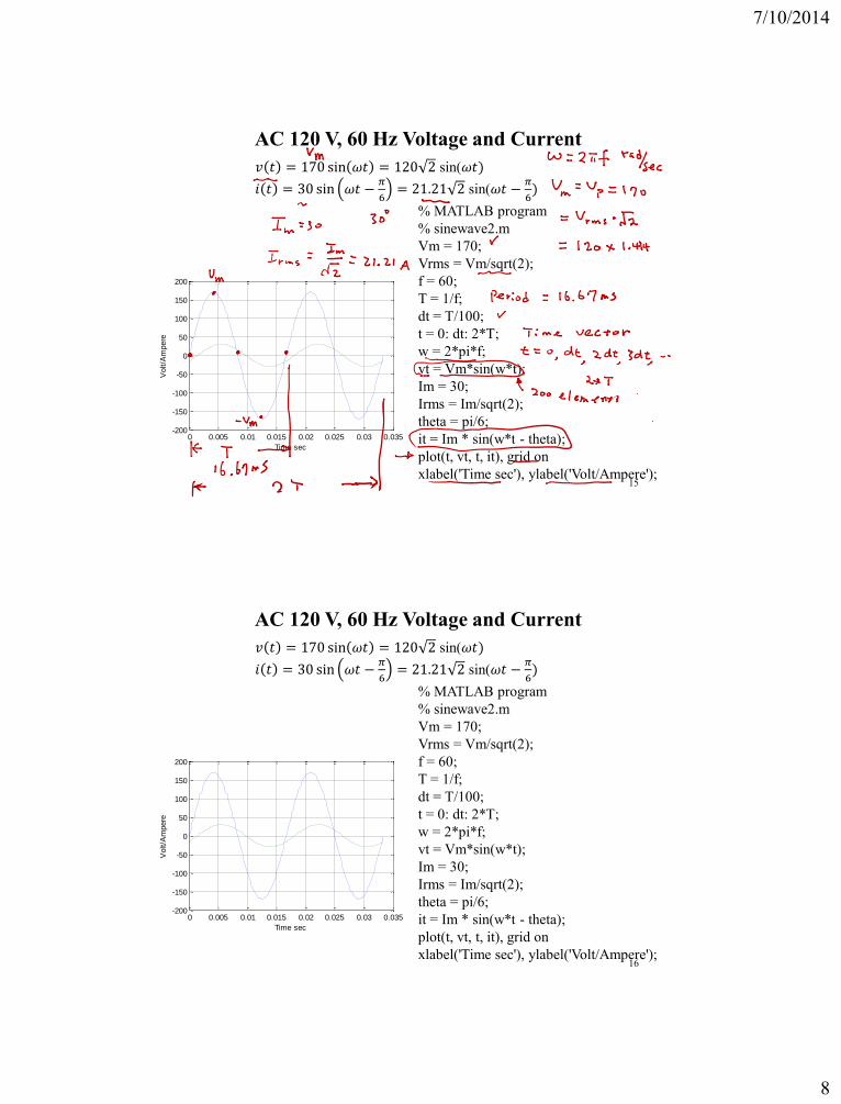
AC 120 V, 60 Hz Voltage and Current
0 0.005 0.01 0.015 0.02 0.025 0.03 0.035-200
-150
-100
-50
0
50
100
150
200
Time sec
Volt/A
mpere
% MATLAB program
% sinewave2.m
Vm = 170;
Vrms = Vm/sqrt(2);
f = 60;
T = 1/f;
dt = T/100;
t = 0: dt: 2*T;
w = 2*pi*f;
vt = Vm*sin(w*t);
Im = 30;
Irms = Im/sqrt(2);
theta = pi/6;
it = Im * sin(w*t - theta);
plot(t, vt, t, it), grid on
xlabel('Time sec'), ylabel('Volt/Ampere');15
𝑣 𝑡 = 170 sin 𝜔𝑡 = 120 2 sin(𝜔𝑡)
𝑖 𝑡 = 30 sin 𝜔𝑡 −𝜋
6= 21.21 2 sin(𝜔𝑡 −
𝜋
6)
AC 120 V, 60 Hz Voltage and Current
0 0.005 0.01 0.015 0.02 0.025 0.03 0.035-200
-150
-100
-50
0
50
100
150
200
Time sec
Volt/A
mpere
% MATLAB program
% sinewave2.m
Vm = 170;
Vrms = Vm/sqrt(2);
f = 60;
T = 1/f;
dt = T/100;
t = 0: dt: 2*T;
w = 2*pi*f;
vt = Vm*sin(w*t);
Im = 30;
Irms = Im/sqrt(2);
theta = pi/6;
it = Im * sin(w*t - theta);
plot(t, vt, t, it), grid on
xlabel('Time sec'), ylabel('Volt/Ampere');16
𝑣 𝑡 = 170 sin 𝜔𝑡 = 120 2 sin(𝜔𝑡)
𝑖 𝑡 = 30 sin 𝜔𝑡 −𝜋
6= 21.21 2 sin(𝜔𝑡 −
𝜋
6)