lecture 2. basics of metal-casting 2.1. casting …1 lecture 2. basics of metal-casting 2.1. casting...
TRANSCRIPT
1
Lecture 2. Basics of Metal-Casting
2.1. Casting methods
Metal casting process begins by creating a mold, which is the ‘reverse’ shape of the part we need. The mold is
made from a refractory material, for example, sand. The metal is heated in an oven until it melts, and the
molten metal is poured into the mould cavity. The liquid takes the shape of cavity, which is the shape of the
part. It is cooled until it solidifies. Finally, the solidified metal part is removed from the mould.
A large number of metal components in designs we use every day are made by casting. The reasons for this
include:
(a) Casting can produce very complex geometry parts with internal cavities and hollow sections.
(b) It can be used to make small (few hundred grams) to very large size parts (thousands of kilograms)
(c) It is economical, with very little wastage: the extra metal in each casting is re-melted and re-used
(d) Cast metal is isotropic – it has the same physical/mechanical properties along any direction.
Common examples: door handles, locks, the outer casing or housing for motors, pumps, etc., wheels of many
cars. Casting is also heavily used in the toy industry to make parts, e.g. toy cars, planes, and so on.
Table 1 summarizes different types of castings, their advantages, disadvantages and examples.
Process Advantages Disadvantages Examples
Sand Wide range of metals, sizes, shapes, low cost
poor finish, wide tolerance engine blocks, cylinder heads
Shell mold better accuracy, finish, higher production rate
limited part size connecting rods, gear housings
Expendable pattern
Wide range of metals, sizes, shapes patterns have low strength cylinder heads, brake components
Plaster mold complex shapes, good surface finish non-ferrous metals, low production rate
prototypes of mechanical parts
Ceramic mold complex shapes, high accuracy, good finish
small sizes impellers, injection mold tooling
Investment complex shapes, excellent finish small parts, expensive jewellery Permanent mold good finish, low porosity, high
production rate Costly mold, simpler shapes only
gears, gear housings
Die Excellent dimensional accuracy, high production rate
costly dies, small parts, non-ferrous metals
precision gears, camera bodies, car wheels
Centrifugal Large cylindrical parts, good quality Expensive, limited shapes pipes, boilers, flywheels

2
2.1.1 Sand casting
Figure 1. Work flow in typical sand-casting foundries [source: www.p2pays.org]
Sand casting uses natural or synthetic sand (lake sand) which is mostly a refractory material called silica
(SiO2). The sand grains must be small enough so that it can be packed densely; however, the grains must be
large enough to allow gasses formed during the metal pouring to escape through the pores. Larger sized molds
use green sand (mixture of sand, clay and some water). Sand can be re-used, and excess metal poured is cut-
off and re-used also.

3
Figure 2. Schematic showing steps of the sand casting process [source: Kalpakjian and Schmid]
Typical sand molds have the following parts (see Figure 2):
• The mold is made of two parts, the top half is called the cope, and bottom part is the drag.
• The liquid flows into the gap between the two parts, called the mold cavity. The geometry of the
cavity is created by the use of a wooden shape, called the pattern. The shape of the patterns is
(almost) identical to the shape of the part we need to make.
• A funnel shaped cavity; the top of the funnel is the pouring cup; the pipe-shaped neck of the funnel
is the sprue – the liquid metal is poured into the pouring cup, and flows down the sprue.
• The runners are the horizontal hollow channels that connect the bottom of the sprue to the mould
cavity. The region where any runner joins with the cavity is called the gate.

4
• Some extra cavities are made connecting to the top surface of the mold. Excess metal poured into the
mould flows into these cavities, called risers. They act as reservoirs; as the metal solidifies inside the
cavity, it shrinks, and the extra metal from the risers flows back down to avoid holes in the cast part.
• Vents are narrow holes connecting the cavity to the atmosphere to allow gasses and the air in the
cavity to escape.
• Cores: Many cast parts have interior holes (hollow parts), or other cavities in their shape that are not
directly accessible from either piece of the mold. Such interior surfaces are generated by inserts called
cores. Cores are made by baking sand with some binder so that they can retain their shape when
handled. The mold is assembled by placing the core into the cavity of the drag, and then placing the
cope on top, and locking the mold. After the casting is done, the sand is shaken off, and the core is
pulled away and usually broken off.
Important considerations for casting:
(a) How do we make the pattern?
Usually craftsmen will carve the part shape by hand and machines to the exact size.
(b) Why is the pattern not exactly identical to the part shape?
- you only need to make the outer surfaces with the pattern; the inner surfaces are made by the core
- you need to allow for the shrinkage of the casting after the metal solidifies
(c) If you intersect the plane formed by the mating surfaces of the drag and cope with the cast part, you will
get a cross-section of the part. The outer part of the outline of this cross section is called the parting line. The
design of the mold is done by first determining the parting line (why ?)
(d) In order to avoid damaging the surface of the mould when removing the pattern and the wood-pieces for
the vents, pouring cup and sprue, risers etc., it is important to incline the vertical surfaces of the part
geometry. This (slight) inclination is called a taper. If you know that your part will be made by casting, you
should taper the surfaces in the original part design.
Figure 3. Taper in design

5
(e) The core is held in position by supporting geometry called core prints (see figure below). If the design is
such that there is insufficient support to hold the core in position, then metal supports called chaplets are used.
The chaplets will be embedded inside the final part.
Mold cavity
chaplet
Mold cavity
chaplet
Figure 4. Design components of a mold showing chaplets
(f) After the casting is obtained, it must be cleaned using air-jet or sand blasting
(g) Finally, the extra metal near the gate, risers and vents must be cut off, and critical surfaces are machined to
achieve proper surface finish and tolerance.
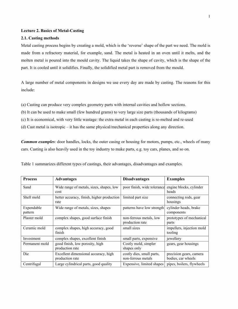
2.1.2. Shell-mold casting
Shell-mold casting yields better surface quality and tolerances. The process is described as follows:
- The 2-piece pattern is made of metal (e.g. aluminum or steel), it is heated to between 175°C-370°C, and
coated with a lubricant, e.g. silicone spray.
- Each heated half-pattern is covered with a mixture of sand and a thermoset resin/epoxy binder. The binder
glues a layer of sand to the pattern, forming a shell. The process may be repeated to get a thicker shell.
- The assembly is baked to cure it.
6
- The patterns are removed, and the two half-shells joined together to form the mold; metal is poured into the
mold.
- When the metal solidifies, the shell is broken to get the part.
Figure 5. Making the shell-mold [Source: Kalpakjian & Schmid] Figure 6. Shell mold casting
2.1.3. Expendable-pattern casting (lost foam process)
The pattern used in this process is made from polystyrene (this is the light, white packaging material which is
used to pack electronics inside the boxes). Polystyrene foam is 95% air bubbles, and the material itself
evaporates when the liquid metal is poured on it.
The pattern itself is made by molding – the polystyrene beads and pentane are put inside an aluminum mold,
and heated; it expands to fill the mold, and takes the shape of the cavity. The pattern is removed, and used for
the casting process, as follows:
- The pattern is dipped in a slurry of water and clay (or other refractory grains); it is dried to get a hard shell
around the pattern.
- The shell-covered pattern is placed in a container with sand for support, and liquid metal is poured from a
hole on top.
- The foam evaporates as the metal fills the shell; upon cooling and solidification, the part is removed by
breaking the shell.

7
The process is useful since it is very cheap, and yields good surface finish and complex geometry. There are
no runners, risers, gating or parting lines – thus the design process is simplified. The process is used to
manufacture crank-shafts for engines, aluminum engine blocks, manifolds etc.
polystyrenepattern
patternsupport
sand
moltenmetal
polystyreneburns;gas escapespolystyrene
pattern
patternsupport
sand
moltenmetal
polystyreneburns;gas escapes
Figure 7. Expendable mold casting
2.1.4. Plaster-mold casting
The mold is made by mixing plaster of paris (CaSO4) with talc and silica flour; this is a fine white powder,
which, when mixed with water gets a clay-like consistency and can be shaped around the pattern (it is the
same material used to make casts for people if they fracture a bone). The plaster cast can be finished to yield
very good surface finish and dimensional accuracy. However, it is relatively soft and not strong enough at
temperature above 1200°C, so this method is mainly used to make castings from non-ferrous metals, e.g. zinc,
copper, aluminum, and magnesium.
Since plaster has lower thermal conductivity, the casting cools slowly, and therefore has more uniform grain
structure (i.e. less warpage, less residual stresses).
2.1.5. Ceramic mold casting
Similar to plaster-mold casting, except that ceramic material is used (e.g. silica or powdered Zircon ZrSiO4).
Ceramics are refractory (e.g. the clay hotpot used in Chinese restaurants to cook some dishes), and also have
higher strength that plaster.
- The ceramic slurry forms a shell over the pattern;
- It is dried in a low temperature oven, and the pattern is removed

8
- Then it is backed by clay for strength, and baked in a high temperature oven to burn off any volatile
substances.
- The metal is cast same as in plaster casting.
This process can be used to make very good quality castings of steel or even stainless steel; it is used for parts
such as impellor blades (for turbines, pumps, or rotors for motor-boats).
2.1.6. Investment casting (lost wax process)
This is an old process, and has been used since ancient times to make jewellery – therefore it is of great
importance to HK. It is also used to make other small (few grams, though it can be used for parts up to a few
kilograms). The steps of this process are shown in the figure 10 below.
An advantage of this process is that the wax can carry very fine details – so the process not only gives good
dimensional tolerances, but also excellent surface finish; in fact, almost any surface texture as well as logos
etc. can be reproduced with very high level of detail.
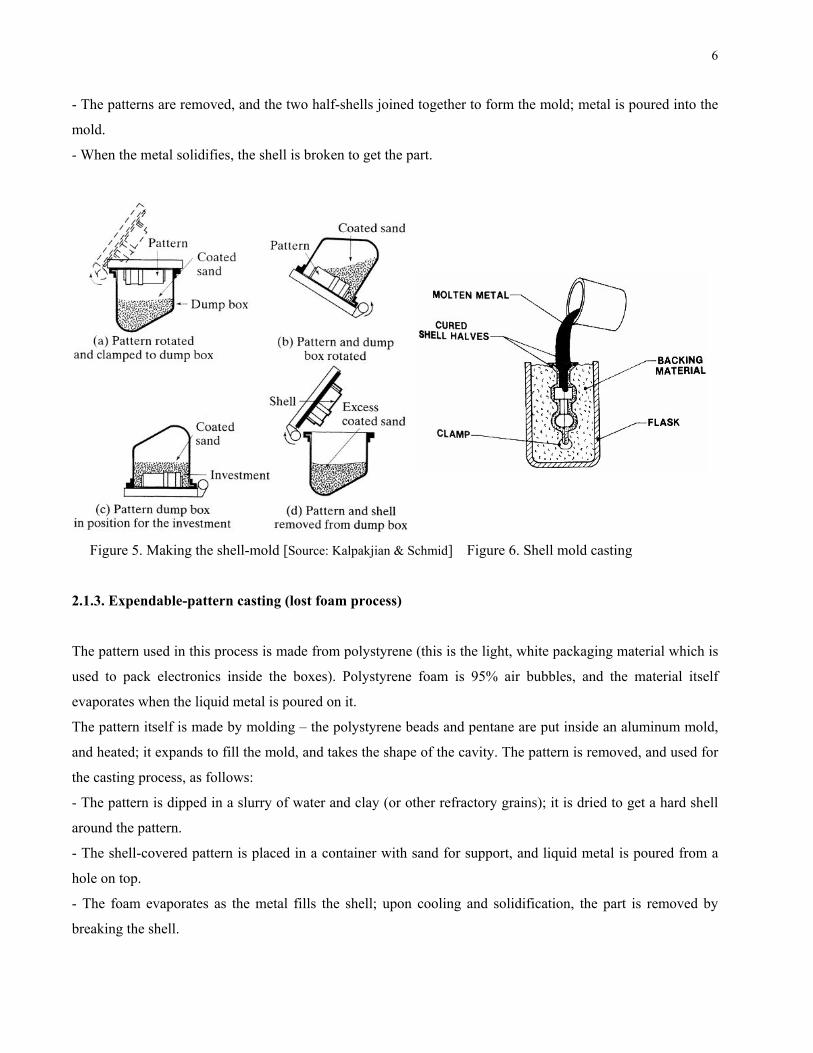
2.1.7. Vacuum casting
This process is also called counter-gravity casting. It is basically the same process as investment casting,
except for the step of filling the mold (step (e) above). In this case, the material is sucked upwards into the
mould by a vacuum pump. The figure 9 below shows the basic idea – notice how the mold appears in an
inverted position from the usual casting process, and is lowered into the flask with the molten metal.
One advantage of vacuum casting is that by releasing the pressure a short time after the mold is filled, we can
release the un-solidified metal back into the flask. This allows us to create hollow castings. Since most of the
heat is conducted away from the surface between the mold and the metal, therefore the portion of the metal
closest to the mold surface always solidifies first; the solid front travels inwards into the cavity. Thus, if the
liquid is drained a very short time after the filling, then we get a very thin walled hollow object, etc. (see
Figure 10).

9
(a) Wax patterns are produced by injection molding
(b) Multiple patterns are assembled to a central wax sprue
(c) A shell is built by immersing the assembly in a liquid ceramic slurry and then into a bed of extremely fine sand. Several layers may be required.
(d) The ceramic is dried; the wax is melted out; ceramic is fired to burn all wax
(e) The shell is filled with molten metal by gravity pouring. On solidification, the parts, gates, sprue and pouring cup become one solid casting. Hollow casting can be made by pouring out excess metal before it solidifies
(g) The parts are cut away from the sprue using a high speed friction saw. Minor finishing gives final part.
(f) After metal solidifies, the ceramic shell is broken off by vibration or water blasting
Figure 8. Steps in the investment casting process [source: www.hitchiner.com]
10
Figure 9. Vacuum casting [source: Kalpakjian & Schmid]
Figure 10. Draining out metal before solidification yields hollow castings [source: Kalpakjian & Schmid]
2.1.8. Permanent mold casting
Here, the two halves of the mold are made of metal, usually cast iron, steel, or refractory alloys. The cavity,
including the runners and gating system are machined into the mold halves. For hollow parts, either
permanent cores (made of metal) or sand-bonded ones may be used, depending on whether the core can be
extracted from the part without damage after casting. The surface of the mold is coated with clay or other hard
refractory material – this improves the life of the mold. Before molding, the surface is covered with a spray of
graphite or silica, which acts as a lubricant. This has two purposes – it improves the flow of the liquid metal,
and it allows the cast part to be withdrawn from the mold more easily. The process can be automated, and
therefore yields high throughput rates. Also, it produces very good tolerance and surface finish. It is
commonly used for producing pistons used in car engines, gear blanks, cylinder heads, and other parts made
of low melting point metals, e.g. copper, bronze, aluminum, magnesium, etc.
11
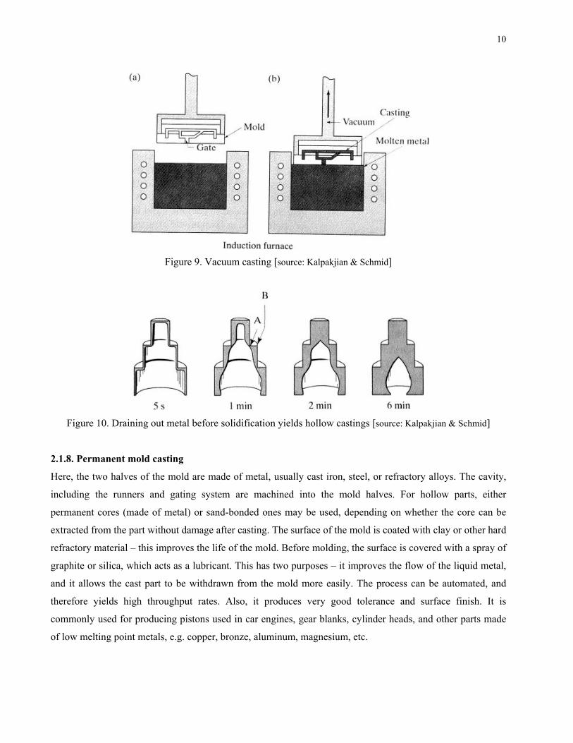
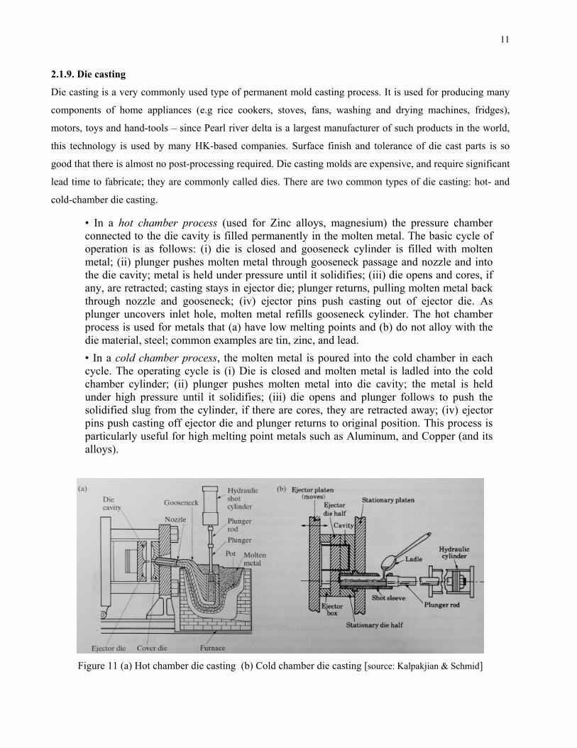
2.1.9. Die casting
Die casting is a very commonly used type of permanent mold casting process. It is used for producing many
components of home appliances (e.g rice cookers, stoves, fans, washing and drying machines, fridges),
motors, toys and hand-tools – since Pearl river delta is a largest manufacturer of such products in the world,
this technology is used by many HK-based companies. Surface finish and tolerance of die cast parts is so
good that there is almost no post-processing required. Die casting molds are expensive, and require significant
lead time to fabricate; they are commonly called dies. There are two common types of die casting: hot- and
cold-chamber die casting.
• In a hot chamber process (used for Zinc alloys, magnesium) the pressure chamber connected to the die cavity is filled permanently in the molten metal. The basic cycle of operation is as follows: (i) die is closed and gooseneck cylinder is filled with molten metal; (ii) plunger pushes molten metal through gooseneck passage and nozzle and into the die cavity; metal is held under pressure until it solidifies; (iii) die opens and cores, if any, are retracted; casting stays in ejector die; plunger returns, pulling molten metal back through nozzle and gooseneck; (iv) ejector pins push casting out of ejector die. As plunger uncovers inlet hole, molten metal refills gooseneck cylinder. The hot chamber process is used for metals that (a) have low melting points and (b) do not alloy with the die material, steel; common examples are tin, zinc, and lead. • In a cold chamber process, the molten metal is poured into the cold chamber in each cycle. The operating cycle is (i) Die is closed and molten metal is ladled into the cold chamber cylinder; (ii) plunger pushes molten metal into die cavity; the metal is held under high pressure until it solidifies; (iii) die opens and plunger follows to push the solidified slug from the cylinder, if there are cores, they are retracted away; (iv) ejector pins push casting off ejector die and plunger returns to original position. This process is particularly useful for high melting point metals such as Aluminum, and Copper (and its alloys).
Figure 11 (a) Hot chamber die casting (b) Cold chamber die casting [source: Kalpakjian & Schmid]

12
2.1.10. Centrifugal casting
Centrifugal casting uses a permanent mold that is rotated about its axis at a speed between 300 to 3000 rpm as
the molten metal is poured. Centrifugal forces cause the metal to be pushed out towards the mold walls, where
it solidifies after cooling. Parts cast in this method have a fine grain microstructure, which is resistant to
atmospheric corrosion; hence this method has been used to manufacture pipes. Since metal is heavier than
impurities, most of the impurities and inclusions are closer to the inner diameter and can be machined away.
surface finish along the inner diameter is also much worse than along the outer surface.
Figure 12. Centrifugal casting schematic [source: Kalpakjian & Schmid]
2.2. Casting design and quality
Several factors affect the quality/performance of cast parts – therefore the design of parts that must be
produced by casting, as well as the design of casting molds and dies, must account for these. You may think
of these as design guidelines, and their scientific basis lies in the analysis – the strength and behavior of
materials.
2.2.1. Corners, angles and section thickness
Many casting processes lead to small surface defects (e.g. blisters, scars, scabs or blows), or tiny
holes/impurities in the interior (e.g. inclusions, cold-shuts, shrinkage cavities). These defects are a problem if
the part with such a defect is subject of varying loads during use. Under such conditions, it is likely that the
defects act like cracks, which propagate under repeated stress causing fatigue failure. Another possibility is
that internal holes act as stress concentrators and reduce the actual strength of the part below the expected
strength of the design. Figure 14 shows the variation of stress in the presence of holes to illustrate the
problem.

13
Figure 13. Typical defects in casting [source: Kalpakjian & Schmid]
2a
2b
σ0
σ0
σmax
σmax = σ0(1 + 2b/a)
2a
2b
σ0
σ0
σmax
σmax = σ0(1 + 2b/a)
Figure 14. Stress concentration near an elliptical defect

14
To avoid these problems
(a) sharp corners should be avoided (these behave like cracks and cause stress concentration
(b) Section changes should be blended smoothly using fillets
(c) Rapid changes in cross-section areas should be avoided; if unavoidable, the mold must be designed to
ensure that metal can flow to all regions and mechanism is provided for uniform and rapid cooling during
solidification. This can be achieved by the use of chills or incorporating fluid-cooled tubes in the mold.
These principles are illustrated in the figures below.
Figure 15. Chills [source: Kalpakjian & Schmid]
Figure 16. Poor and preferred design examples [source: Kalpakjian & Schmid]
15
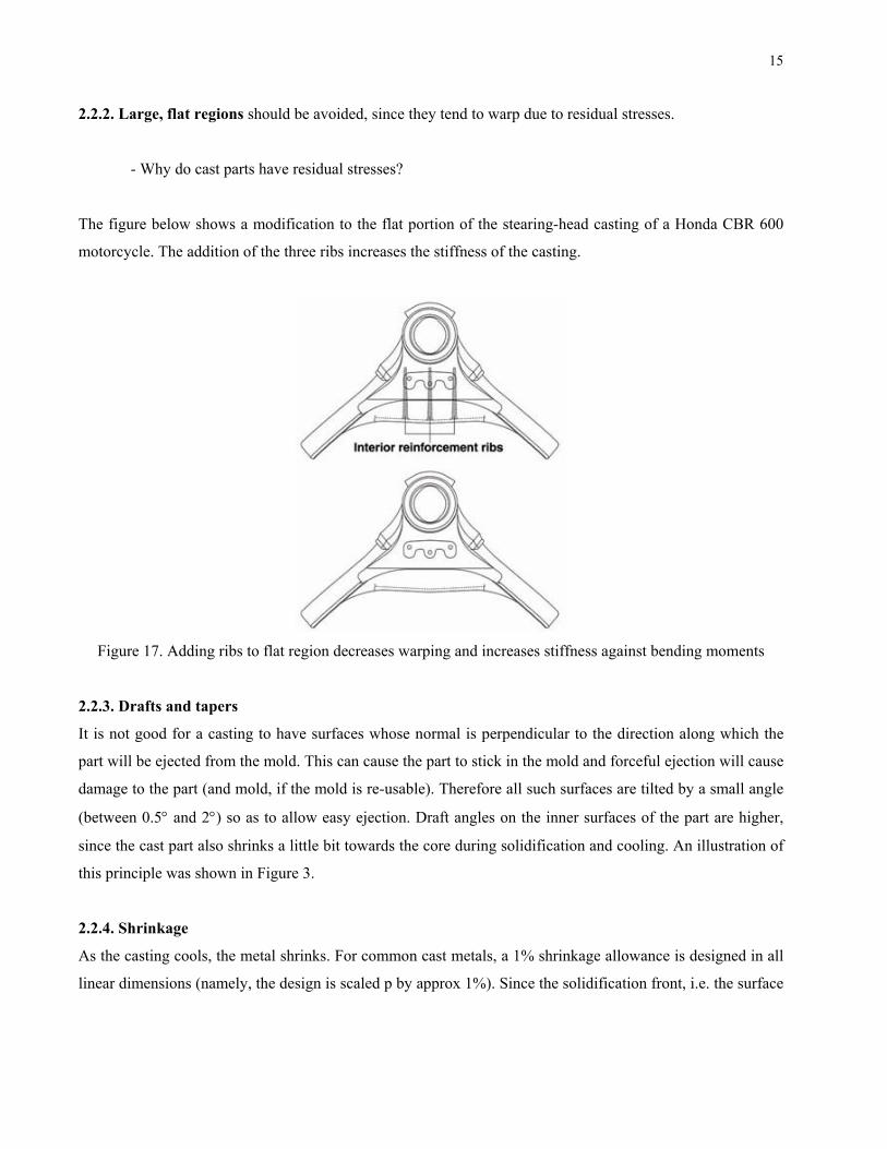
2.2.2. Large, flat regions should be avoided, since they tend to warp due to residual stresses.
- Why do cast parts have residual stresses?
The figure below shows a modification to the flat portion of the stearing-head casting of a Honda CBR 600
motorcycle. The addition of the three ribs increases the stiffness of the casting.
Figure 17. Adding ribs to flat region decreases warping and increases stiffness against bending moments
2.2.3. Drafts and tapers
It is not good for a casting to have surfaces whose normal is perpendicular to the direction along which the
part will be ejected from the mold. This can cause the part to stick in the mold and forceful ejection will cause
damage to the part (and mold, if the mold is re-usable). Therefore all such surfaces are tilted by a small angle
(between 0.5° and 2°) so as to allow easy ejection. Draft angles on the inner surfaces of the part are higher,
since the cast part also shrinks a little bit towards the core during solidification and cooling. An illustration of
this principle was shown in Figure 3.
2.2.4. Shrinkage
As the casting cools, the metal shrinks. For common cast metals, a 1% shrinkage allowance is designed in all
linear dimensions (namely, the design is scaled p by approx 1%). Since the solidification front, i.e. the surface

16
at the boundary of the solidified and the liquid metals, travels from the surface of the mold to the interior
regions of the part, the design must ensure that shrinkage does not cause cavities.
Figure 18. Poor and preferred design examples [source: Kalpakjian & Schmid]
2.2.5. Parting line
The parting line is the boundary where the cope, drag and the part meet. If the surface of the cope and drag
are planar, then the parting line is the outline of the cross-section of the part along that plane. You can easily
see the parting line for many cast and molded parts that you commonly use. It is conventional that the parting
line should be planar, if possible. A very small of metal will always “leak” outside the mold between the cope
and the drag in any casting. This is called the “flash”. If the flash is along an external surface, it must be
machined away by some finishing operation. If the parting line is along an edge of the part, it is less visible –
this is preferred.
Figure 19. Parting line examples [source: Kalpakjian & Schmid]