lead free astm upvc solvent weld plumbing · pdf filelead free astm upvc solvent weld plumbing...
TRANSCRIPT

STRONG NAHIN, ASTRAL STRONG!! TM
For Residential & Commercial Applications
MCGM
APPROVED
MCGM
APPROVED
UV
RESISTANT
UV
RESISTANT
LEAD FREE ASTM UPVC SOLVENT WELD PLUMBING SYSTEM
Technical Manual

INDEX
01 Certification & Approvals ........................................................... 01
02 Introduction ................................................................................ 02
03 Key Properties............................................................................. 03
04 The Difference Between uPVC & PVC / Field of Applications ..... 04
05 Standards & Specifications ......................................................... 05
06 Pressure Pipe and Fittings........................................................... 06
07 PVC SCH 40 and SCH 80 Fittings...................................................07
08 Basic Socket Dimensions............................................................. 08
09 uPVC SCH 40 & SCH 80 Pressure Fittings .................................... 09
10 uPVC Pressure Pipes / uPVC Solvent Cement & Primer .............. 17
11 Installation Procedures ............................................................... 18
12 Joint Curing / Support Spacing For uPVC Pipe ............................ 19
13 Carrying Capacity & Friction Loss For SCH 40 Pipe ......................20
14 Carrying Capacity & Friction Loss For SCH 80 Pipe ..................... 21
15 Testing Pressure System.............................................................. 22
16 Expansion and Contraction of uPVC Pipe.................................... 23
17 Underground Installation............................................................ 24
18 Handling & Storage ..................................................................... 25
19 Frequently Asked Questions ....................................................... 26

CERTIFICATES & APPROVALS
01 www.astralcpvc.com

ASTRAL have been relentless in its commitment to quality and service. Through the years,
ASTRAL have broadened and enhanced its product line to serve better to the customers.
ASTRAL was first to introduce FlowGuard CPVC pipes and fittings in Indian market and now
repeating its tradition, ASTRAL is very proud to introduce Lead Free ASTM uPVC Solvent Weld
Plumbing System ‘ASTRAL Aquarius’ under the brand name . ASTRAL Aquarius ASTM uPVC
pipes and fittings are and hence non toxic, easy to install and are made for life time Lead Free
trouble free service. ASTRAL Aquarius pipes and fittings are available in range of 15 mm (½”)
to 300 mm (12”) with two different class SCH 40 and SCH 80.
As the full line leading manufacturer of CPVC pipes and fittings for residential and industrial
applications and now with ASTM uPVC pressure pipes and fittings, ASTRAL can be your one
stop source for all the plastic piping system you require for lifetime plumbing solution.
PVC is one of the specified thermoplastic for piping system
components, including valves, fittings, flanges and many
speciality products. PVC has excellent chemical and
corrosion resistance to a broad range of fluids. ASTRAL
uPVC materials conform to ASTM Cell Classification 12454‐
B of ASTM D1784 (formally designated as Type I, Grade I).
The maximum recommended service temperature of PVC
products is 60°C (140°F)
PVC ‐ POLYVINYL CHLORIDE
PVC makes a major contribution to the quality, safety and
cost‐effectiveness of construction materials, as well as
helping to reduce the environmental impact of completed
projects.
PVC is the most widely used polymer in building and
construction applications and over 50 percent of Western
Europe’s annual PVC production is used in this sector.
PVC has a versatility that helps to meet modern and future
design needs.
WHAT MAKES PVC IMPORTANT?
ASTRAL Aquarius uPVC solvent joint plumbing system
makes its pressure bearing capacity twice than that of the
threaded pipe.
BENEFITS OF ASTRAL AQUARIUS SYSTEM OVER OTHER uPVC SYSTEMS
ASTRAL Aquarius uPVC pipes being lead free are
non‐toxic and hence favoured for use in applications such
as potable water pipes. ASTRAL Aquarius uPVC Plumbing
system utilizes NSF (National Sanitation Foundation)
approved one ‐step solvent cement, specifically formulated
for the use. Joining is accomplished quickly and efficiently
utilizing inexpensive tools thereby greatly reducing labor
and installation costs.
THREADEDUPVC PIPE
SOLVENT WELDUPVC PIPE
ASTRAL Aquarius uPVC pipes & fittings exhibit the well‐
known physical characteristics and other benefits of
conventional uPVC piping such as good chemical and
corrosion resistance, low thermal conductivity, high
strength‐to‐weight ratio, good impact resistance and ease
of installation.
02www.astralcpvc.com
INTRODUCTION

KEY PROPERTIES
03 www.astralcpvc.com
The key properties of ASTRAL Aquarius high pressure Lead Free Plumbing System are significant with following features
• STRONG AND LIGHT WEIGHT
ASTRAL Aquarius Lead Free Plumbing System is tough, durable with high tensile and impact strength. The system is light in weight and can be transported easily from one place to another.
• EASY TO INSTALL
ASTRAL Aquarius Lead Free pipes can be cut, shaped, welded and jointed easily.
• FIRE RESISTANT
ASTRAL Aquarius Lead Free Plumbing System is inherently difficult to ignite and stops burning once the source of heat is removed. Compared to its common plastic alternatives PVC performs better in terms of lower combustibility, flammability, flame propagation and heat release. Newly developed advantages in terms of lower acid emissions, smoke generation and enhanced fire resistance.
• DURABLE
ASTRAL Aquarius Lead Free Plumbing System is durable and free from weaknesses caused by rusting, weathering and chemical action and hence last for life time.
• UV STABILIZED
ASTRAL Aquarius Lead Free Plumbing System can be used in sunlight exposed conditions. However, ASTRAL recommends a standard grade of exterior latex paint (water base) which will protect the system adequately.
• SIMPLE AND LEAK PROOF JOINTS
Jointing can be done speedily with special IPS solvent cement supplied by the company which ensures 100% leak proof joints.
• SAFE MATERIAL FOR DRINKING WATER
ASTRAL Aquarius pipes are non‐toxic and lead free which makes them a safe material for potable water. It is also the world's most researched and thoroughly tested material for PVC which meets all international standards for safety and health for both the products and applications.
• MAXIMUM FLOW RATE
Smooth inner surface ensures high flow rate and low friction losses. The system is leach and scale free.
• GOOD INSULATOR
PVC does not conduct electricity. ASTRAL Aquarius pipes are non conductor of electricity so it make the plumbing system safe when working with electrical tools or equipments.
• CHEMICAL RESISTANCE
uPVC is generally inert to most mineral acids, bases, salts and paraffinic hydrocarbon solutions. For more information on uPVC chemical resistance refer to Chemical Resistance of Rigid Vinyls Based.
• WIDE RANGE
ASTRAL Aquarius Lead Free Plumbing System available from ½" (15 mm) to 12" (300 mm) with wide range of fittings, transition fittings, valves and specially designed brass inserted fittings to suit any design criteria.
EASY TO INSTALL FIRE RESISTANCE CHEMICAL RESISTANCEUV STABILIZED

04www.astralcpvc.com
THE DIFFERENCE BETWEEN uPVC & PVC
FIELD OF APPLICATIONS• Cold Water Plumbing Application
• Water Distribution Mains
• Industrial Process Lines
• Swimming Pools
• Plants & Tanning Plants
• Hand Pumps
PLUMBINGAPPLICATION
SUGAR, PAPER &DISTILLERY INDUSTRIES
RING LINESDOWN TAKE LINES HAND PUMPS
• Sugar, Paper & Distillery Industries
• Salt Water Line
• Aggressive Corrosive Fluid Transportation
• Coal Washing & Ash Handling
• Ring Lines
• Down Take Lines
There has been a lot of confusion in the
thermoplastics industry regarding the use of the terms
uPVC and PVC when specifying thermoplastic piping
products. For many years, certain regions of the world have
preferred using the term uPVC when specifying
unplasticized Polyvinyl Chioride piping products while
other regions of the world, The United State of America for
instance, prefer the acronmy PVC (less the U) when
specifying the same unplasticized PVC piping products.
Essentially, both references indicate that the type of PVC
required be unplasticized, rigid PVC.
The most important aspect of specifying PVC piping
products is not the abbreviation but the cell classification
of the thermoplastic material. For rigid, unplasticized Type
I Grade 1 PVC material with a hydrostatic design stress of
2000psi the cell classification is 12454. These numbers
indicate the minimum physical properties that a rigid,
unplasticized thermoplastic compound must meet per
ASTM D1784 to be used in the manufacture of pressure
piping components.
In summary, whether a thermoplastic vinyl piping, product
is specified as uPVC is not important, it is the cell
classification, and materials’ physical properties that is
most important.

STANDARDS & SPECIFICATIONS
05 www.astralcpvc.com
ASTM D 1784 ‐ Rigid Poly Vinyl Chloride (PVC) Compounds.
ASTM D 1785 ‐ Poly Vinyl Chloride (PVC) Plastic Pipes, SCH 40 & SCH 80.
ASTM D 2466 ‐ Socket type Poly Vinyl Chloride (PVC) Plastic Pipe Fittings, SCH 40.
ASTM D 2467 ‐ Socket type Poly Vinyl Chloride (PVC) Plastic Pipe Fittings, SCH 80.
ASTM D 2564 ‐ Solvent Cements for Plastic Pipes & Fittings
ASTM F 1498 ‐ Taper Pipe threads 60° for Thermoplastics Pipe & Fittings
ASTM D 2774 ‐ Underground Installation of Thermoplastic Pipes.
ISO 7/1 ‐ Pipe threads where pressure joints are made on threads ‐
Part 1 : Designation, Dimension & Tolerances.
ASTM ‐ American Society for Testing of Materials.
BSP ‐ British Standard Pipe
NPT ‐ National Pipe Threads (ANSI)
MIPT ‐ Male Iron Pipe Threads
SPIGOT ‐ Spigot End (IPS)
MBSP ‐ Male BSP Threads
PVC ‐ Poly Vinyl Chloride
ANSI ‐ American National Standards Institute
IPS ‐ Iron Pipe Size (ASTM)
FIPT ‐ Female Iron Pipe Threads
SOCKET ‐ Solvent Weld Socket
FBSP ‐ Female BSP Threads
NSF ‐ National Sanitation Foundation
EPDM ‐ Ethylene Propylene Rubber
DESCRIPTIVE CODES
WATER HAMMER :
ASTRAL recommends that all uPVC Plastic piping systems be
designed and constructed to avoid excessive WATER
HAMMER. Water hammer can cause damage and failure to
pipe, valves and fittings within the piping system.
THREADED CONNECTIONS :
Use a quality grade thread sealant. Do not use substances
that could cause stress cracking to plastic. Major attention
must be given while making plastic thread joints. 1 to 2
turns beyond FINGER TIGHT is generally all that is required
to make a sound plastic connection. Unnecessary OVER
TIGHTENING will cause DAMAGE TO BOTH PIPES &
FITTINGS. Also give proper attention while selecting the
threaded fittings, as ASTRAL manufacture some fittings with
IMPORTANT FOR INSTALLERS & USERS :
NPT threads & some fittings with BSP threads to give more
versatility to customer NPT threads are not compatible
with BSP threads.
SEAL & GASKET LUBRICANTS :
Some Lubricants, including vegetable oils are known to
cause stress cracking in thermoplastics materials. A mild
soap or commercially available pipe gasket lubricants
suitable for uPVC is recommended where lubrication is
required for installation or maintenance service (especially
with Flange joints). Choice of lubricant is at the discretion
of the installer.
FLOW VELOCITIES :
System should not be operated or flushed out at flow
velocities greater than 5 feet per second.
06www.astralcpvc.com
PRESSURE PIPES AND FITTINGS
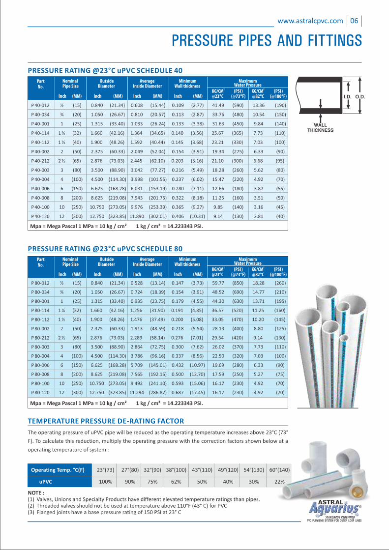
PRESSURE RATING @23°C uPVC SCHEDULE 40
½ (15 0.840 21.34 0.608 15.44 0.109 2.77 41.49 590 190) ( ) ( ) ( ) ( ) 13.36 ( )
¾ 20 1.050 26.67 0.810 20.57 0.113 2.87 33.76 480 150( ) ( ) ( ) ( ) ( ) 10.54 ( )
1 25 1.315 33.40 1.033 26.24 0.133 3.38 31.63 450 140( ) ( ) ( ) ( ) ( ) 9.84 ( )
1 ¼ 32 1.660 42.16 1.364 34.65 0.140 3.56 25.67 365 110( ) ( ) ( ) ( ) ( ) 7.73 ( )
1 ½ 1.900 48.26 1.592 40.44 0.145 3.68 23.21 330 100(40) ( ) ( ) ( ) ( ) 7.03 ( )
2 50 2.375 60.33 2.049 52.04 0.154 3.91 19.34 275 90( ) ( ) ( ) ( ) ( ) 6.33 ( )
2 ½ 65 2.876 73.03 2.445 62.10 0.203 5.16 21.10 300 95( ) ( ) ( ) ( ) ( ) 6.68 ( )
3 80 3.500 88.90 3.042 77.27 0.216 5.49 18.28 260 80( ) ( ) ( ) ( ) ( ) 5.62 ( )
4 100 4.500 114.30 3.998 101.55 0.237 6.02 15.47 220 70( ) ( ) ( ) ( ) ( ) 4.92 ( )
6 150 6.625 168.28 6.031 153.19 0.280 7.11 12.66 180 55( ) ( ) ( ) ( ) ( ) 3.87 ( )
8 200 8.625 219.08 7.943 201.75 0.322 8.18 11.25 160 50( ) ( ) ( ) ( ) ( ) 3.51 ( )
10 250 10.750 273.05 9.976 253.39 0.365 9.27 9.85 140 45( ) ( ) ( ) ( ) ( ) 3.16 ( )
12 300) 12.750 323.85 11.890 302.01 0.406 10.31 9.14 130 40( ( ) ( ) ( ) ( ) 2.81 ( )
P 40‐012
P 40‐034
P 40‐001
P 40‐114
P 40‐112
P 40‐002
P 40‐212
P 40‐003
P 40‐004
P 40‐006
P 40‐008
P 40‐100
P 40‐120
Mpa = Mega Pascal 1 MPa = 10 kg / cm² 1 kg / cm² = 14.223343 PSI.
Nominal Average Minimum MaximumOutside Pipe Size Inside Diameter Water PressureDiameter Wall thickness
( ) Inch (MM) Inch (MM) Inch (MM)
2 2 KG/CM PSI KG/CM (PSI)Inch (MM) @23°C (@73°F) @82°C (@180°F)
PartNo.
The operating pressure of uPVC pipe will be reduced as the operating temperature increases above 23°C (73°
F). To calculate this reduction, multiply the operating pressure with the correction factors shown below at a
operating temperature of system :
Operating Temp. °C(F) 23°(73) 27°(80) 32°(90) 38°(100) 43°(110) 49°(120) 54°(130) 60°(140)
uPVC 100% 90% 75% 62% 50% 40% 30% 22%
NOTE :(1) Valves, Unions and Specialty Products have different elevated temperature ratings than pipes.(2) Threaded valves should not be used at temperature above 110°F (43° C) for PVC(3) Flanged joints have a base pressure rating of 150 PSI at 23° C
½ (15 0.840 21.34 0.528 13.14 0.147 3.73 59.77 850 18.28 260)) ( ) ( ) ( ) ( ) (
¾ 20 1.050 26.67 0.724 18.39 0.154 3.91 48.52 690 14.77 210( ) ( ) ( ) ( ) ( ) ( )
1 25 1.315 33.40 0.935 23.75 0.179 4.55 44.30 630 13.71 195( ) ( ) ( ) ( ) ( ) ( )
1 ¼ 32 1.660 42.16 1.256 31.90 0.191 4.85 36.57 520 11.25 160( ) ( ) ( ) ( ) ( ) ( )
1 ½ 40 1.900 48.26 1.476 37.49 0.200 5.08 33.05 470 10.20 145( ) ( ) ( ) ( ) ( ) ( )
2 50 2.375 60.33 1.913 48.59 0.218 5.54 28.13 400 8.80 125( ) ( ) ( ) ( ) ( ) ( )
2 ½ 65 2.876 73.03 2.289 58.14 0.276 7.01 29.54 420 9.14 130( ) ( ) ( ) ( ) ( ) ( )
3 80 3.500 88.90 2.864 72.75 0.300 7.62 26.02 370 7.73 110( ) ( ) ( ) ( ) ( ) ( )
4 100 4.500 114.30 3.786 96.16 0.337 8.56 22.50 320 7.03 100( ) ( ) ( ) ( ) ( ) ( )
6 150 6.625 168.28 5.709 145.01 0.432 10.97 19.69 280 6.33 90( ) ( ) ( ) ( ) ( ) ( )
8 200 8.625 219.08 7.565 192.15 0.500 12.70 17.59 250 5.27 75( ) ( ) ( ) ( ) ( ) ( )
10 250 10.750 273.05 9.492 241.10 0.593 15.06 16.17 230 4.92 70( ) ( ) ( ) ( ) ( ) ( )
12 300 12.750 323.85 11.294 286.87 0.687 17.45 16.17 230 4.92 70( ) ( ) ( ) ( ) ( ) ( )
P 80‐012
P 80‐034
P 80‐001
P 80‐114
P 80‐112
P 80‐002
P 80‐212
P 80‐003
P 80‐004
P 80‐006
P 80‐008
P 80‐100
P 80‐120
Nominal Average Minimum MaximumOutside Pipe Size Inside Diameter Water PressureDiameter Wall thickness
( ) Inch (MM) Inch (MM) Inch (MM)
2 2 KG/CM PSI KG/CM (PSI)Inch (MM) @23°C (@73°F) @82°C (@180°F)
PartNo.
Mpa = Mega Pascal 1 MPa = 10 kg / cm² 1 kg / cm² = 14.223343 PSI.
PRESSURE RATING @23°C uPVC SCHEDULE 80
TEMPERATURE PRESSURE DE‐RATING FACTOR

PVC SCHEDULE 40 AND SCHEDULE 80 FITTINGS
07 www.astralcpvc.com
PVC SCHEDULE 40 AND SCHEDULE 80 FITTINGSSUGGESTED MAXIMUM INTERNAL WORKING PRESSURE @ 73°F (23°C)
Notes:1‐Water pressure Ratings At 73°F (23°C) for Schedule 40 and Schedule 80 Plastic Pipe, ASTM D 1785 for PVC.2‐Threading of Schedule 40 plastic pipe is not permitted. Recommended pressures apply to molded fittings only.
½ 42.19 25.31 21.09 59.76 35.85 29.88
¾ 33.75 20.24 16.87 48.51 29.10 24.25
1 31.64 18.98 15.81 44.29 26.57 22.14
1¼ 26.01 15.60 13.00 36.56 21.93 18.27
1½ 23.20 13.92 11.60 33.04 19.82 16.52
2 19.69 11.81 9.84 28.12 16.87 14.06
2½ 21.09 12.65 10.54 29.53 17.71 14.76
3 18.28 10.96 9.13 26.01 15.60 13.00
4 15.47 9.28 7.73 22.50 13.49 11.24
6 12.66 7.59 6.32 19.69 11.81 9.84
8 11.25 6.74 5.62 17.57 10.54 8.78
10 9.84 5.90 4.92 16.17 9.70 8.08
12 9.14 5.48 4.56 16.17 9.70 8.08
Nominal Size
(in.)
2Schedule 80 kg / cm
Solvent CementedJoint
Standard ThreadedJoint
1Pipe 1PipeStandard Threaded3Joint
Solvent CementedJoint
2Schedule 40 kg / cm
Not For Use With Compressed Air or Gas
The following information is provided as a guide only. Actual allowable working pressure may very widely according to field conditions.
Additionally, pressure de‐rating at elevated temperatures must be taken into account. Certain fitting configurations may have other assigned
pressure limitations (i.e., Wyes, Unions, Flanges, Valves etc). Contact Astral Technical Services for additional information.
PHYSICAL PROPERTIES OF PVC MATERIALS
Above data is based upon information provided by the raw material manufacturers.It should be used only as a recommendation and not as a guarantee of performance.
PROPERTY UNITS PVC ASTM NO.
Specific GravityTensile Strength (73°F)Modulus of Elasticty in Tension (73°F)Flexural Strength (73°F)Izod Impact (notched at 73°FHardness (Durometer D)Hardness (Rockwell R)Compressive Strength (73°F)Hydrostatic Design StressCoefficient of Linear ExpansionHeat Deflection Temperature at 66 psiCoefficient of Thermal ConductivitySpecific HeatLimiting Oxygen IndexWater Absorption (24 hrs at 73°F)Cell Classification‐PipeCell Classification‐Fittings
g/ccPSIPSIPSIft lb/in.‐‐‐‐‐‐‐‐PSIPSIin./in./°Fdegrees °FBTU/hr/sq. ft/°F/in.BTU/F/lb%% weight gain‐‐‐‐‐‐‐‐
1.41 ‐ 1.467,2004,60,00013,2000.6580 ± 3110 ‐ 1209,0002,000
‐53.1 x 101651.20.25430.0512454‐B12454‐B
D 792D 638D 638D 790D 256D 2240D 785D 695D 1598D 696D 648C 177D 2766D 2863D 570D 1784D 1784

08www.astralcpvc.com
BASIC SOCKET DIMENSIONS
AMERICAN NATIONAL STANDARD TAPER PIPE THREADS (NPT)ANSI STANDARD B1.20.1 ASTM STANDARD F 1498
½ 15 14 0.5337 0.07143
¾ 20 14 0.5457 0.07143
1 25 11½ 0.6828 0.08696
1¼ 32 11½ 0.7068 0.08696
1½ 40 11½ 0.7235 0.08696
2 50 11½ 0.7565 0.08696
2½ 65 8 1.1375 0.12500
3 80 8 1.2000 0.12500
4 100 8 1.3000 0.12500
NOMINAL SIZE
THREADSPER IN.
EFFECTIVETHREAD
LENGTH L
PITCH OFTHREAD P
(IN.) (MM)
NOMINAL SIZE
½ 15 0.848 0.836 ±0.004 0.688 0.875
¾ 20 1.058 1.046 ±0.004 0.719 1.000
1 25 1.325 1.310 ±0.005 0.875 1.125
1¼ 32 1.670 1.655 ±0.005 0.938 1.250
1½ 40 1.912 1.894 ±0.006 1.094 1.375
2 50 2.387 2.369 ±0.006 1.156 1.500
2½ 65 2.889 2.868 ±0.007 1.750 1.750
3 80 3.516 3.492 ±0.008 1.875 1.875
4 100 4.518 4.491 ±0.009 2.000 2.250
6 150 6.647 6.614 ±0.011 3.000 3.000
8 200 8.655 8.610 ±0.015 4.000 4.000
10 250 10.780 10.735 ±0.015 5.000 5.000
12 300 12.780 12.735 ±0.015 6.000 6.000
ENTRANCEA
TOLERANCE
SOCKET LENGTH MINIMUM C (IN.)DIAMETER (IN.)
BOTTOMB
SCH 40 SCH 80(IN.) (MM)
SCHEDULE 40 AS PER ASTM D‐2466, SCHEDULE 80 AS PER ASTM D‐2467
NPT BSPT
BSP ISO 7/1 PARELLEL THREADS
½ 15 14 13.152 1.8143
¾ 20 14 14.514 1.8143
1 25 11 16.714 2.3091
1¼ 32 11 19.050 2.3091
1½ 40 11 19.050 2.3091
2 50 11 23.378 2.3091
2½ 65 11 26.698 2.3091
3 80 11 29.873 2.3091
4 100 11 35.791 2.3091
NOMINAL SIZE
THREADSPER IN.
EFFECTIVETHREAD
LENGTH L
PITCH OFTHREAD P
(IN.) (MM)

uPVC PRESSURE FITTINGS
09 www.astralcpvc.com
SCHEDULE 40 AS PER ASTM D‐2466 AND SCHEDULE 80 AS PER ASTM D‐2467
SCHEDULE 40 SCHEDULE 80
Size Size Part No. Std Pkg Part No. Std Pkg (in.) (mm) Bag/Case Bag/Case
TEE ‐ SOC ½ 15 M 401‐005 50/ 550 ¾ 20 M 401‐007 25/ 300 1 25 M 401‐010 25/ 150 1¼ 32 M 401‐012 10/ 100 1½ 40 M 401‐015 10 / 70 2 50 M 401‐020 5/ 40 2½ 65 M 401‐025 1 / 27 3 80 M 401‐030 1 / 18 4 100 M 401‐040 1 / 10 6 150 M 401‐060 1 / 2 8 200 – –
M 801‐005 50 / 200 M 801‐007 25 / 125 M 801‐010 10 / 70 M 801‐012 10 / 40 M 801‐015 5 / 30 M 801‐020 5 / 15 M 801‐025 1 / 12 M 801‐030 1 / 7 M 801‐040 1 / 4 M 801‐060 1 / 2 M 801‐080 1 / 1
REDUCING TEE ‐ SOC ¾ x ½ 20 x 15 M 401‐101 25 / 300 1 x ½ 25 x 15 M 401‐130 25/ 200 1 x ¾ 25 x 20 M 401‐131 25/ 150 1¼ x ½ 32 x 15 M 401‐166 10/ 100 1¼ x ¾ 32 x 20 M 401‐167 10/ 100 1¼ x 1 32 x 25 M 401‐168 10/ 100 1½ x ½ 40 x 15 M 401‐209 10 / 80 1½ x ¾ 40 x 20 M 401‐210 10/ 40 1½ x 1 40 x 25 M 401‐211 10/ 70 1½ x 1¼ 40 x 32 M 401‐212 10/ 70 2 x ½ 50 x 15 M 401‐247 5/ 35 2 x ¾ 50 x 20 M 401‐248 5 / 35 2 x 1 50 x 25 M 401‐249 5 / 35 2 x 1¼ 50 x 32 M 401‐250 5 / 50 2 x 1½ 50 x 40 M 401‐251 5 / 50 2½ x 1 65 x 25 ‐ ‐ 1¼ ‐ ‐2½ x 65 x 32 2½ x 1½ 65 x 40 ‐ ‐ 2½ x 2 65 x 50 ‐ ‐ 3 x 1 80 x 25 ‐ ‐ 3 x 1¼ 80 x 32 ‐ ‐ 3 x 1½ 80 x 40 ‐ ‐ 3 x 2 80 x 50 ‐ ‐ 3 x 80 x 65 2½ ‐ ‐ 4 x 1 ‐ ‐100 x 25 4 x 1¼ ‐ ‐100 x 32 4 x 1½ ‐ ‐100 x 40 4 x 2 100 x 50 * 401‐420 5 / ‐‐ 4 x 2½ 100 x 65 4 x 3 100 x 80 * 401‐422 5 / ‐‐ 6 x 4 150 x 100 * 401‐532 1 /‐‐
M 801‐101 25 / 150 M 801‐130 25 / 100 M 801‐131 25 / 100 M 801‐166 10 / 60 M 801‐167 10 / 60 M 801‐168 10 / 50 M 801‐209 10/ 50 M 801‐210 10 / 40 M 801‐211 10/ 40 M 801‐212 10 / 30 M 801‐247 5/ 30 M 801‐248 5 / 25 M 801‐249 5/ 20 M 801‐250 5 / 20 M801‐251 5/ 20 M 801‐289 15 M 801‐290 15 M 801‐291 15 M801‐292 12 M801‐335 10 M801‐336 10 M801‐337 10 M801‐338 9 M801‐339 9 M801‐417 5 M801‐418 5 M801‐419 5 M801‐420 5 M801‐421 5 M801‐422 5
½ 15 M 402‐005 50 / 250 ¾ 20 M 402‐007 25 / 125 1 25 M 402‐010 25 / 75 1¼ 32 M 402‐012 10 / 40 1½ 40 M 402‐015 10 / 30 2 50 M 402‐020 5 / 20
TEE ‐ SOC X FIPT
* Trading Item

10www.astralcpvc.com
uPVC PRESSURE FITTINGSSCHEDULE 40 AS PER ASTM D‐2466 AND SCHEDULE 80 AS PER ASTM D‐2467
SCHEDULE 40 SCHEDULE 80
Size Size Part No. Std Pkg Part No. Std Pkg (in.) (mm) Bag/Case Bag/Case
½ 15 M 407‐005 100 / 300 ¾ 20 M 407‐007 50 / 200 1 25 M 407‐010 25 / 100 1¼ 32 M 407‐012 10 / 50 1½ 40 M 407‐015 10 / 40 2 50 M 407‐020 5 / 25
90° ELBOW ‐ SOC X FIPT
½ x ½ 15 x 15 ¾ x ½ 20 x 15 ¾ x¾ 20 x 20 1 x ½ 25 x 15 1 x ¾ 25 x 20 1 x 1 25 x 25 1¼ x ½ 32 x 15
M 801‐005B 25 / 100 M 801‐101B 25 / 50 M 801‐007B 25 / 50 M 801‐130B 25 / 25 M 801‐131B 25 / 25 ‐ ‐ M 801‐166B ‐‐ / 20
BRASS TEE‐ SOC X FIPT
#
½ x ½ 15 x 15 ¾ x ½ 20 x 15 ¾ x ¾ 20 x 20 1 x ½ 25 x 15 1 x 1 25 x 25 1 x ¾ 25 x 20
M 806‐005B 25 / 100 M 806‐101B 25 / 100 M 806‐007B 25 / 75 M 806‐130B 25 / 50 ‐ ‐ M 806‐131B 25 / 50
BRASS 90° ELBOW ‐ SOC X FIPT
#
# Shortly Introducing
½ 15 M 406‐005 100 / 800 ¾ 20 M 406‐007 50 / 400 1 25 M 406‐010 25 / 250 1¼ 32 M 406‐012 10 / 150 1½ 40 M 406‐015 10 / 100 2 50 M 406‐020 5 / 60 2½ 65 M 406‐025 1 / 35 3 80 M 406‐030 1 / 25 4 100 M 406‐040 1 / 12 6 150 M 406‐060 1‐ / 3 8 200 – –
M 806‐005 50 / 300 M 806‐007 50 / 200 M 806‐010 25 / 125 M 806‐012 10 / 60 M 806‐015 10 / 50 M 806‐020 5 / 25 M 806‐025 5 / 15 M 806‐030 1 / 10 M 806‐040 1 / 5 M 806‐060 1 / 2 M 806‐080 1 / 1
90° ELBOW ‐ SOC

uPVC PRESSURE FITTINGS
11 www.astralcpvc.com
SCHEDULE 40 AS PER ASTM D‐2466 AND SCHEDULE 80 AS PER ASTM D‐2467
SCHEDULE 40 SCHEDULE 80
Size Size Part No. Std Pkg Part No. Std Pkg (in.) (mm) Bag/Case Bag/Case
* Trading Item # Shortly Introducing
¾ x ½ 20 x 15 ‐ ‐ 1 x ½ 25 x 15 ‐ ‐ 1 x ¾ 25 x 20 ‐ ‐
M 806‐101 50 / 200 M 806‐130 25 / 150 M 806‐131 25 / 150
REDUCER ELBOW
45° ELBOW ‐ SOC ½ 15 M 417‐005 100 / 500 ¾ 20 M 417‐007 50 / 250 1 25 M 417‐010 25 / 300 1¼ 32 M 417‐012 10 / 80 1½ 40 M 417‐015 10 / 60 2 50 M 417‐020 10 / 30 2½ 65 * 417‐025 5 / ‐‐ 3 80 * 417‐030 5 / ‐‐ 4 100 * 417‐040 5 / ‐‐
M 817‐005 100 / 400 M 817‐007 50 / 200 M 817‐010 25 / 150 M 817‐012 10 /80 M 817‐015 10 / 60 M 817‐020 5 / 30 M 817‐025 5 / 20 M 817‐030 1 / 12 M 817‐040 1 / 6
CROSS ‐ SOC ½ 15 M 420‐005 50 / 200 ¾ 20 M 420‐007 50 / 100 1 25 * 420‐010 10 / ‐‐ 1¼ 32 * 420‐012 10 / ‐‐ 1½ 40 * 420‐015 10 / ‐‐ 2 50 * 420‐020 10 / ‐‐
REDUCER COUPLING SOC ¾ x ½ 20 x 15 M 429‐101 100 / 300 1 x ½ 25 x 15 M 429‐130 50 / 500 1 x ¾ 25 x 20 M 429‐131 50 / 200 1¼ x 1 32 x 25 M 429‐168 25/ 150 1½ x 1 40 x 25 M 429‐211 25 / 150 1½ x 1¼ 40 x 32 M 429‐212 10 / 150 2 x 1 50 x 25 M 429‐249 ‐ 2 x 1¼ 50 x 32 M 429‐250 10 / 40 2 x 1½ 50 x 40 M 429‐251 10 / 50 2½ x 1¼ 65 x 32 M 429‐290 ‐ 2½ x 1½ 65 x 40 M 429‐291 ‐ 2½ x 2 65 x 50 M 429‐290 ‐ 3 x 80 x 40 1½ M 429‐337 ‐ 3 x 2 80 x 50 * 429‐338 5 / ‐‐ 3 x 2½ 80 x 65 M 429‐339 ‐ 4 x 100 x 40 ‐1½ M 429‐419 4 x 2 100 x 50 * 429‐420 5 / ‐‐ 4 x 2½ 100 x65 M 429‐421 ‐ 4 x 3 100 x 80 * 429‐422 5 /‐‐
M 829‐250 ‐ M 829‐251 10 / 50 M 829‐290 8 / 48 M 829‐291 5 / 40 M 829‐292 5 / 40 M 829‐337 1 / 27 M 829‐338 5 / 25 M 829‐339 5 / 25 M 829‐419 / 1 16 M 829‐420 1 / 16 M 829‐421 1 / 15 M 829‐422 / 1 15
# #
#

12www.astralcpvc.com
uPVC PRESSURE FITTINGSSCHEDULE 40 AS PER ASTM D‐2466 AND SCHEDULE 80 AS PER ASTM D‐2467
SCHEDULE 40 SCHEDULE 80
Size Size Part No. Std Pkg Part No. Std Pkg (in.) (mm) Bag/Case Bag/Case
* Trading Item
COUPLING SOC ½ 15 M 429‐005 100/ 1200 ¾ 20 M 429‐007 50 / 300 1 25 M 429‐010 25/ 300 1¼ 32 M 429‐012 10 / 200 1½ 40 M 429‐015 10 / 150 2 50 M 429‐020 10/ 100 2½ 65 M 429‐025 5 / 50 3 80 M 429‐030 5 / 35 4 100 M 429‐040 1 / 24 6 150 M 429‐060 1 / 2 8 200 ‐ ‐ 10 250 ‐ ‐ 12 300 ‐ ‐
M 829‐005 100 / 500 M 829‐007 50 / 300 M 829‐010 25 / 150 M 829‐012 10 / 80 M 829‐015 10 / 70 M 829‐020 10 / 50 M 829‐025 5 / 20 M 829‐030 5 / 15 M 829‐040 1 / 12 M 829‐060 1 / 2 M 829‐080 1 / 1 M 829‐100 1 / 1 M 829‐120 1 / 1
M 835‐005B 25 / 100 M 835‐007B 25 / 100 M 835‐010B 25 / 50 M 835‐012B 10 / 40 M 835‐015B 10 / 30 M 835‐020B 5 / 15 M 835‐101B 25 / 100 M 829‐130B 25 / 100 M 8 ‐131B / 10029 25
½ 15 ¾ 20 1 25 1¼ 32 1½ 40 2 50 ¾ x ½ 20 x 15 1 x ½ 25 x 15 1 x ¾ 25 x 20
BRASS FEMALE ADAPTER ‐ SOC X FBSP
M 836‐005B 50 / 250 M 836‐007B 25 / 150 M 836‐010B 25/ 100 M 836‐012B 10 / 50 M 836‐015B 10 / 40 M 836‐020B 5 / 20 M 836‐101B 25 / 150 M 836‐130B / 10025 M 836‐131B 25 / 100
½ 15 ¾ 20 1 25 1¼ 32 1½ 40 2 50 ¾ x ½ 20 x 15 1 x ½ 25 x 15 1 25 x 20 x ¾
BRASS MALE ADAPTER ‐ SOC X MBSP
M 837‐130B 50 / 250
BRASS REDUCER BUSH 25 X 15 1 x ½

uPVC PRESSURE FITTINGS
13 www.astralcpvc.com
SCHEDULE 40 AS PER ASTM D‐2466 AND SCHEDULE 80 AS PER ASTM D‐2467
SCHEDULE 40 SCHEDULE 80
Size Size Part No. Std Pkg Part No. Std Pkg (in.) (mm) Bag/Case Bag/Case
* Trading Item
½ 15 M 897‐005 50 / 200 ¾ 20 M 897‐007 25 / 120 1 25 M 897‐010 10 / 80 1¼ 32 M 897‐012 10 / 50 1½ 40 M 897‐015 10 / 80 2 50 M 897‐020 5 / 30 2½ 65 * 897‐025 5 / ‐‐ 3 80 5 / ‐‐* 897‐030 4 100 5 / ‐‐* 897‐040 6 150 3 / * 897‐060 ‐‐
UNION SOC WITH EPDM O‐ RING SEAL
½ 15 M 335‐005 100 / 1200 ¾ 20 M 335‐007 50 / 350 1 25 M 335‐010 25 / 350 1¼ 32 M 335‐012 10 / 100 1½ 40 M 335‐015 10 / 100 2 50 M 335‐020 10 / 50 ¾ x ½ 20 x 15 M 335‐101 50 / 600 2½ 65 3 80 4 100
M 835‐005 100 / 600 M 835‐007 50 / 400 M 835‐010 25 / 200 M 835‐012 10 / 100 M 835‐015 10 / 80 M 835‐020 10 / 50 ‐ ‐ M 835‐025 5 / 30 M 835‐ 030 5 / 20 M 835‐040 1 / 12
FEMALE ADAPTER ‐ Soc x FBSP
½ 15 M 447‐005 100 / 1000 ¾ 20 M 447‐007 100 / 500 1 25 M 447‐010 50 / 300 1¼ 32 M 447‐012 10 / 150 1½ 40 M 447‐015 10 / 250 2 50 M 447‐020 10 / 80 2½ 65 M 447‐025 5 / 50 3 80 M 447‐030 5 / 25 4 100 M 447‐040 1 / 15 6 150 * 447‐060 1 / ‐‐
M 847‐005 100 / 800 M 847‐007 50 / 500 M 847‐010 50 / 300 M 847‐012 10 / 150 M 847‐015 10 / 100 M 847‐020 10 / 60 M 847‐025 5 / 40 M 847‐030 5 / 25 M 847‐040 1/18 * 847‐060 1 / ‐‐
CAP ‐ SOC
MALE ADAPTER ‐ SOC X MBSP ½ 15 M 336‐005 100 / 1500 ¾ 20 M 336‐007 50 / 400 1 25 M 336‐010 50 / 500 1¼ 32 M 336‐012 10 / 300 1½ 40 M 336‐015 10 / 200 2 50 M 336‐020 10/ 150 2½ 65 * 336‐025 10 / ‐‐ 3 80 * 336‐030 10 / ‐‐ 4 100 * 336‐040 6 / ‐‐ 6 150 * 336‐060 3 / ‐‐ ¾ x ½ 20 x 15 ‐ ‐
M 836‐005 100 / 600 M 836‐007 50 / 400 M 836‐010 50 / 250 M 836‐012 10 / 150 M 836‐015 10 / 100 M 836‐020 10 / 60 M 836‐025 5 / 30 M 836‐030 5 / 20 M 836‐040 1 / 15
M 836‐101 50 / 400

14www.astralcpvc.com
uPVC PRESSURE FITTINGSSCHEDULE 40 AS PER ASTM D‐2466 AND SCHEDULE 80 AS PER ASTM D‐2467
* Trading Item
SCHEDULE 80
Size Size Part No. Std Pkg Part No. Std Pkg (in.) (mm) Bag/Case Bag/Case
¾ x ½ 20 x 15 M 437‐101 100 / 800 1 x ½ 25 x 15 M 437‐130 50 / 400 1 x ¾ 25 x 20 M 437‐131 50 / 400 1¼ x ½ 32 x 15 M 437‐166 25 / 200 1¼ x ¾ 32 x 20 M 437‐167 25 / 200 1¼ x 1 32 x 25 M 437‐168 25 / 400 1½ x ½ 40 x 15 M 437‐209 25 / 350 1½ x ¾ 40 x 20 M 437‐210 25 / 175 1½ x 1 40 x 25 M 437‐211 25 / 350 1½ x 1¼ 40 x 32 M 437‐212 25 / 300 2 x ½ 50 x 15 M 437‐247 10 / 100 2 x ¾ 50 x 20 M 437‐248 10 / 100 2 x 1 50 x 25 M 437‐249 10 / 100 2 x 1¼ 50 x 32 M 437‐250 10 / 100 2 x 1½ 50 x 40 M 437‐251 10 / 100 2½ x 1¼ 65 x 32 M 437‐290 5 / 25 2½ x 1½ 65 x 40 M 437‐291 5 / 50 2½ x 2 65 x 50 M 437‐292 / 505 3 x 1½ 80 x 40 M 437‐337 / 355 3 x 2 80 x 50 M 437‐338 / 355 3 x 2½ 80 x 65 M 437‐339 / 355 4 x 2 100 x 50 M 437‐420 / 205 4 x 2½ 100 x 65 M 437‐421 / 105 4 x 3 100 x 80 M 437‐422 / 205 6 x 3 150 x 80 * 437‐530 3 / ‐‐ 6 x 4 150 x 100 * 437‐532 3 / ‐‐ 8 x 6 200 x 150 * 437‐585 1 / ‐‐
M 837‐101 100 / 300 M 837‐130 50 / 400 M 837‐131 50 / 400 M 837‐167 25 / 250 M 837‐166 25 / 250 M 837‐168 25 / 250 M 837‐209 25 / 150 M 837‐210 25 / 150 M 837‐211 25 / 150 M 837‐212 25 / 150 M 837‐247 10 / 100 M 837‐248 10 / 100 M 837‐249 10 / 100 M 837‐250 10 / 100 M 837‐251 10 / 100 M 837‐290 5 / 50 M 837‐291 5 / 50 M 837‐292 5 / 50 M 837‐337 5 / 35 M 837‐338 5 / 35 M 837‐339 5 / 35 M 837‐420 5 / 20 M 837‐421 5 / 20 M 837‐422 5 / 20 M 837‐530 1 / 6 M 837‐532 1 / 6 M 837‐585 1 / 3
REDUCER BUSHING (FLUSH STYLE)
½ 15 M 2622‐005 D 1/80 ¾ 20 M 2622‐007 D 1/120 1 25 M 2622‐010 D 1/50 1¼ 32 M 2622‐012 D 1/40 1½ 40 M 2622‐015 D 1/30 2 50 M 2622‐020 D 1/15 2½ 65 * 2622‐025 6 / ‐‐ 3 80 * 2622‐030 4 / ‐‐ 4 100 * 2622‐040 1 / ‐‐ 6 150 * 2622‐060 1 / ‐‐
BALL VALVE‐SOC
½ 15 T 2622‐005 1/48 ¾ 20 2622‐007 1/36T 1 25 2622‐010 1/16T 1¼ 32 2622‐012 1/10T 1½ 40 2622‐015 1/8T 2 50 2622‐020 1/6T
BALL VALVE (ASTRAL)
½ 15 * 448‐005 50 / ‐‐ ¾ 20 * 448‐007 25 / ‐‐ 1 25 * 448‐010 25 / ‐‐ 1¼ 32 * 448‐012 10 / ‐‐ 1½ 40 * 448‐015 10 / ‐‐ 2 50 * 448‐020 10 / ‐‐ 2½ 65 * 448‐025 10 / ‐‐ 3 80 * 448‐030 10 / ‐‐
CAP FIPT

15 www.astralcpvc.com
uPVC PRESSURE FITTINGS
Size Size Part No. Std Pkg (in.) (mm) Bag/Case
½ 15 M 806 ‐ 005 FB 120 ¾ 20 M 406 ‐ 007 FB 85 1 25 M 406 ‐ 010 FB 50 1¼ 32 M 406 ‐ 012 FB 30 1½ 40 M 406 ‐ 015 FB 18 2 50 M 406 ‐ 020 FB 12
LONG RADIUS BEND 90°
½ 15 P 12 ‐ F SOB 90 ¾ 20 P 034 ‐ SOBF 60 1 25 P 1 ‐ SOBF 30 1¼ 32 P 114 ‐ SOBF 25 1½ 40 P 112 ‐ SOBF 20 2 50 P 2 ‐ SOBF 10
STEP OVER BEND
½ 15 M 470‐005 10/80 ¾ 20 M 470‐007 10/60 1 25 M 470‐010 10/40 1¼ 32 M 470‐012 10/30 1½ 40 M 470‐015 10/20 2 50 M 470‐020 5/15
TANK ADAPTER
½ 15 M470‐005FB 10 / 40 ¾ 20 M470‐007FB 10 / 30 1 25 M470‐010FB 5 / 25 1¼ 32 M470‐012FB 5 / 20 1½ 40 M470‐015FB 5 / 15 2 50 M470‐020FB 5 / 10
TANK ADAPTER (PIPE THREAD STYLE)
½ 15 M‐PLUG ‐ 12I 300 ¾ 20 M‐PLUG ‐ 34I 200
END PLUG THREADS

16www.astralcpvc.com
uPVC PRESSURE FITTINGS
* Trading Item
½ 15 M 854‐005 10/120 ¾ 20 M 854‐007 10/80 1 25 M 854‐010 10/60 1¼ 32 M 854‐012 5/50 1½ 40 M 854‐015 5/35 2 50 M 854‐020 5/25 2½ 65 M 854‐025 1/15 3 80 M 854‐030 1/12 4 100 M 854‐040 1/8 6 150 854‐060 M 1/3 8 200 854‐080 M 1/1
VANSTONE FLANGE ‐ SOC
Size Size Part No. Std Pkg (in.) (mm) Bag/Case
2½ 65 * 853‐025 5 / ‐‐ 3 80 M 853‐030 1 / 20 4 100 M 853‐040 1 / 17 6 150 * 853‐060 1 / ‐‐
BLIND FLANGE
2½ 65 * 851‐025 5 / ‐‐ 3 80 M 851‐030 1 / 12 4 100 M 851‐040 1 / 8 6 150 * 851‐060 1 / ‐‐
ONE PIECE FLANGE ‐ SOC
2½ 65 * 856‐025 5 / ‐‐ 3 80 M 856‐030 1 / 10 4 100 M 856‐040 1 / 6 6 150 * 856‐060 1 / ‐‐
VANSTONE FLANGE ‐ SPIG
½ 15 PVC 9120 M 100 / 800 ¾ 20 PVC 9340 M 100 / 500 1 25 PVC 9100 M 100 / 400 1¼ 32 PVC 9105 M 50 / 300 1½ 40 PVC 9106 M 50 / 250 2 50 PVC 9200 M 50 / 200
METAL STRAP

uPVC PRESSURE PIPES
SCHEDULE 40 SCHEDULE 80
Size Size Part No. Std Pkg Part No. Std Pkg (in.) (mm) Bag/Case Bag/Case
3MTR
½ 15 P40‐012 50
¾ 20 P40‐034 30
1 25 P40‐001 20
1¼ 32 P40‐114 15
1½ 40 P40‐112 10
2 50 P40‐002 8
2½ 65 P40‐212 5
3 80 P40‐003 3
4 100 P40‐004 2
6 150 P40‐006 1
8 200 P40‐008 1
10 250 P40‐100 1
12 300 P40‐120 1
3MTR
P80‐012 50
P80‐034 30
P80‐001 20
P80‐114 15
P80‐112 10
P80‐002 8
P80‐212 5
P80‐003 3
P80‐004 2
P80‐006 1
P80‐008 1
P80‐100 1
P80‐120 1
uPVC PRESSURE PIPES SCHEDULE 40 & SCHEDULE 80 AS PER ASTM D‐1785
AS PER ASTM D‐2564
473 ML TE2 ‐ 221 12 946 ML 12TE2 ‐ 220
PRIMER Std Pkg P 70 Part No. Case
HEAVY BODIED Std Pkg PVC 717 Part No. Case 473 ML TIPS ‐ 473 P 717 12 946 ML 12TIPS ‐ 946 P 717
AS PER ASTM D‐2564AS PER ASTM D‐2564
MEDIUM BODIED Std Pkg PVC 705 Part No. Case 22 ML 22 P705 As Req.TIPS ‐ 44 ML TIPS ‐ As Req.44 P705 50 ML TIPS ‐ 50 P705 48 118 ML 118 P705 24TIPS ‐ 237 ML P705 24TIPS ‐ 237 473 ML P705 12TIPS ‐ 473 946 ML P705 12TIPS ‐ 946
uPVC SOLVENT CEMENT & PRIMER
17 www.astralcpvc.com

INSTALLATION PROCEDURES
• Observe all safety precautions.
• Systems should be installed in a good and
workmanlike manner consistent
with normal industry standards and in
conformance with all local plumbing, fire and
building code requirements. Failure to
follow proper installation practices,
procedures or techniques can result in system
failure, property damage or personal
injury.
• Pipes and fittings should be used for their
intended purpose as defined by
local plumbing and building codes and the
applicable ASTM standards.
• Follow manufacturers instructions for all related
products.
uPVC cement for SCH 40 and interference fitPipe Size
(In.)(MM)
½‐2
15‐50mm
2½‐12
65‐300mm
Cement
Type
Medium
Bodied
Heavy
Bodied
Min.
Vis. (cP)
500
1600
IPS‐
Weld On
705
717
uPVC cement for SCH 80 and interference fitPipe Size
(In.)(MM)
½‐1¼
15‐32mm
1½‐12
40‐300mm
Cement
Type
Medium
Bodied
Heavy
Bodied
Min.
Vis. (cP)
500
1600
IPS‐
Weld On
705
717
• Cut pipe square. As joints are sealed at the base of the fitting socket. An angled cut may result in joint failure.• Acceptable tools include miter saw, mechanical cut off saw or wheel cutter. Wheel type cutters must employ a blade designed for plastics.
• Remove all burr from inside and outside of pipe with a knife‐edge, fi le or deburring tool. Chamfer (bevel) the end of the pipe 10O ‐ 15OCLEAN• Remove surface dirt, grease or moisture with a clean dry cloth.
CUT PIPE
REMOVE BURR & BEVEL
DRY FIT
APPLICATOR
CEMENT
JOIN PIPE & FITTING
• With light pressure, pipe should go one third to one half of the way into the fitting socket. Pipes and Fittings that are too tight or too loose should not be used.
• Use an applicator that is one half the pipe diameter.• Too large an applicator will force excessive cement in to the inside of small diameter fittings. Too small an applicator will not apply sufficient cement to large diameter systems.
• Apply a full even layer of cement to the outside of a pipe and medium layer of cement to the inside of a fitting.
• Assemble pipe and fitting socket till it contacts socket bottom. Give pipe a quarter turn. Hold pipe and fitting together until th pipe dose not back out.• Remove excessive cement from the exterior. A properly made joint will show a continuous bead of cement around the perimeter.
N.B. : Primers must be used in solvent cement joints of uPVC plastic pipe and fittings for size above 2".
18www.astralcpvc.com

JOINT CURINGRecommended initial set times. Recommended initial cure times.
SUPPORT SPACING FOR uPVC PIPEAdequate supports for any piping system is a matter of great importance. In practice, support spacings are a function of pipe size operating temperatures, the location of heavy valves or fittings and the mechanical properties of the pipe material.
To ensure the satisfactory operation of a ASTRAL Aquarius uPVC piping system, the location and type of hangers should be carefully considered. Hangers should not compress, distort, cut or abrade the piping.
All piping should be supported with an approved hanger at intervals sufficiently close to maintain correct pipe alignment and to prevent sagging or geade reversal. Pipe should also be supported at all branch ends and at all changes of direction. Support trap arms as close as possible to the trap. In keeping with good plumbing practices support and brace all closet bends and fasten closet flanges.
1. Concentrated loads should be supported directly so as to eliminate high stress concentrations. Should this be impractical then the pipe must be supported immediately adjacent to the load.
2. In systems where large fluctuations in temperature occur, allowances must be made for expansion and contraction of the piping system. Since changes in direction in the system are usually sufficient to allow for expansion and contraction hangers must be placed so as not to restrict this movement.
3. Since plastic pipe expands or contracts approximately five times greater than those of steel, hangers should not restrict this movement.
4. Hangers should provide as much bearing surface as possible. To prevent damage to the pipe, file smooth any sharp edges or burrs on the hangers or supports.
5. Support spacing for horizontal piping systems is determined by the maximum operating temperature the system will encounter. The piping should be supported on uniform centers with supports that do not restrict the axial movement.
6. For vertical lines, it is recommended that an engineer should design the vertical supports according to the vertical load involved.
Temperature°CNom.Pipe Size
½ 15 4 ½ 4 ½ 4 2½ 2½ ¾ 20 5 4 ½ 4 2½ 2½ 1 25 5 ½ 5 4½ 3 2½ 1 ¼ 32 5 ½ 5 ½ 5 3 3 1 ½ 40 6 5 ½ 5 3½ 3 2 50 6 5 ½ 5 3½ 3 2 ½ 65 6 ½ 6 5½ 4 3 3 80 7 7 6 4 3½ 4 100 7 ½ 7 6½ 4½ 4 6 150 8 ½ 8 7½ 5 4½ 8 200 9 ½ 9 8½ 5½ 5 10 250 10 ½ 9 ½ 9 6½ 5½ 12 300 12 10 ½ 9½ 7 6
(in.) (mm) 15.5 26.6 37.7 48.8 60
Schedule ‐ 40 Recommended Support spacing (in feet)
½ 15 5 4 ½ 4 ½ 3 2½ ¾ 20 5 ½ 5 4 ½ 3 2½ 1 25 6 5 ½ 5 3½ 3 1 ¼ 32 6 6 5 ½ 3½ 3 1 ½ 40 6 ½ 6 5 ½ 3½ 3½ 2 50 7 6 ½ 6 4 3½ 2 ½ 65 7 ½ 7 ½ 6 ½ 4½ 4 3 80 8 7 ½ 7 4½ 4 4 100 9 8 ½ 7 ½ 5 4½ 6 150 10 9 ½ 8 ½ 6½ 5½ 8 200 11 10 9 ½ 7½ 6 10 250 12 ½ 11 10 ½ 8 7 12 300 13 12 10 ½ 7½ 6½
Temperature°CNom.Pipe Size
(in.) (mm) 15.5 26.6 37.7 48.8 60
Schedule ‐ 80 Recommended Support spacing (in feet)
NOTE : The above information provides general guidelines. It should be used only as a reference and not as a guarantee of performance. Specific installation instructions and techniques may be required as a result of local plumbing and building codes, engineering specifications and instructions.
19 www.astralcpvc.com

CA
UT
ION
: F
low
ve
locity s
ho
uld
no
t e
xce
ed
5 f
ee
t p
er
se
co
nd
. P
VC
pip
e c
an
no
t b
e u
se
d f
or
co
mp
resse
d a
ir s
erv
ice
.
20www.astralcpvc.com

CA
UT
ION
: F
low
velo
city s
hould
not
exceed 5
feet
per
second.
PV
C p
ipe c
annot
be u
sed f
or
com
pre
ssed a
ir s
erv
ice.
21 www.astralcpvc.com

TESTING PRESSURE SYSTEM
1. Prior to testing, safety precautions should be instituted
to protect personnel and property in case of test failure.
2. Conduct pressure testing with water. DO NOT USE AIR
OR OTHER GASES for pressure testing.
3. The piping system should be adequately anchored to
limit movement. Water under pressure exerts thrust
forces in piping systems. Thrust blocking should be
provided at changes of direction, change in size and at
dead ends.
4. Please refer tables given for initial set & cure times
before pressure testing.
5. The piping systems should be slowly filled with water,
taking care to prevent surge and air entrapment. The
flow velocity should not exceed feet per second.
6. All trapped air must be slowly released. Vents must be
provided at all high points of the piping system. All valves
and air relief mechanisms should be opened so that the
air can be vented while the system is extremely
dangerous and it must be slowly and completely vented
prior to testing. For sizes 4" & above, ASTRAL
recommends to use automatic air relief valves at every
300‐400mtr. distance & at furthest & highest points of
pipeline to avoid any damage to the piping system.
7. The piping system can be pressurized to 125% of its
designed working pressure. However care must be taken
to ensure the pressure does not exceed the working
pressure of the lowest rated component in the system
(valves, unions, flanges, threaded parts etc.)
8. The pressure test should not exceed one hour. Any
leaking joints or pipe must be cut out and replaced and
the line recharged and retested using the same
procedure.
22www.astralcpvc.com
TESTING PRESSURE SYSTEMEXPANSION AND CONTRACTION OF uPVC PIPECARRYING CAPACITY AND FRICTION LOSS FOR SCHEDULE 80 THERMOPLASTIC PIPE
uPVC pipes, like other piping materials, undergo length changes as a result of temperature variations above and below the installation temperature. They expand and contract 4.5 to 5 times more than steel or iron pipe. The extent of the expansion ‐ contraction depends upon the coefficient of linear expansion of piping material. The length of pipe between directional changes, and the temperature differential.
The coefficient of thermal expansion (Y)for uPVC is 3.1 x 10‐5 in./in./°F.
The amount of expansion or contraction can becalculated using the following formula :
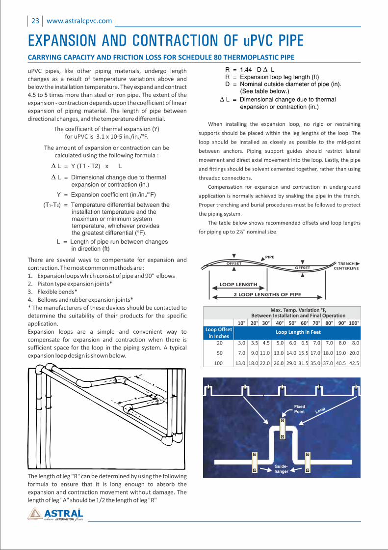
There are several ways to compensate for expansion and contraction. The most common methods are :1. Expansion loops which consist of pipe and 90° elbows2. Piston type expansion joints*3. Flexible bends*4. Bellows and rubber expansion joints** The manufacturers of these devices should be contacted to determine the suitability of their products for the specific application.Expansion loops are a simple and convenient way to compensate for expansion and contraction when there is sufficient space for the loop in the piping system. A typical expansion loop design is shown below.
The length of leg "R" can be determined by using the following formula to ensure that it is long enough to absorb the expansion and contraction movement without damage. The length of leg "A" should be 1/2 the length of leg "R"
LOOP LENGTH
2 LOOP LENGTHS OF PIPE
OFFSETOFFSET
PIPE
TRENCHCENTERLINE
3.0 3.5 4.5 5.0 6.0 6.5 7.0 7.0 8.0 8.0
7.0 9.0 11.0 13.0 14.0 15.5 17.0 18.0 19.0 20.0
13.0 18.0 22.0 26.0 29.0 31.5 35.0 37.0 40.5 42.5
20
50
100
Max. Temp. Variation °F,Between Installation and Final Operation
Loop Offsetin Inches
Loop Length in Feet
10° 20° 30° 40° 50° 60° 70° 80° 90° 100°
Guide-hanger
FixedPoint Loop
When installing the expansion loop, no rigid or restraining
supports should be placed within the leg lengths of the loop. The
loop should be installed as closely as possible to the mid‐point
between anchors. Piping support guides should restrict lateral
movement and direct axial movement into the loop. Lastly, the pipe
and fittings should be solvent cemented together, rather than using
threaded connections.
Compensation for expansion and contraction in underground
application is normally achieved by snaking the pipe in the trench.
Proper trenching and burial procedures must be followed to protect
the piping system.
The table below shows recommended offsets and loop lengths
for piping up to 2½" nominal size.
23 www.astralcpvc.com

UNDERGROUND INSTALLATION
uPVC pipes and fittings can be installed underground, Since these piping systems are flexible systems, proper attention should be given to burial conditions. The stiffness of the piping system is affected by sidewall support, soil compaction, and the condition of the trench, Trench bottoms should be smooth and regular in either undisturbed soil or a layer of compacted backfill. Pipe must lie evenly on this surface throughout the entire length of its barrel, Excavation, bedding and backfill should be in accordance with the provision of the local Plumbing Code having jurisdiction.
The following trenching and burial procedures should be used
to protect the piping system.
1. The trench should be excavated to ensure the sides will be
stable under all working conditions. The trench should be
wide enough to provide adequate room for the following:
A. Jointing the pipe in the trench.
B. Snaking the pipe from side or side to compensate for
expansion and contraction.
C. Filling and compacting the side fills.
The space between the pipe and trench wall must be
wider than the compaction equipment used in the
compaction of the backfill. Minimum width shall not be
less than the greater of either the pipe outside diameter
plus 16 inches of the pipe outside diameter times 1.25 plus
12 inches. Trench width may be different if approved by
the design engineer.
2. The trench bottom should be smooth, free of rocks and
debris, continuous, and provide uniform support. If ledge
rock, hardpan or large boulders are encountered, the
trench bottom should be padded with bedding of
TRENCHING compacted granular material to a thickness of at least 4
inches. Foundation bedding should be installed as
required by the engineer.
3. Trench depth is determined by the pipe’s service
requirements. Plastic pipe should always be installed at
least below the frost level. The minimum cover for lines
subject to heavy overhead traffic is 24 inches.
4. A smooth, trench bottom is necessary to support the pipe
over its entire length on firm stable material. Blocking
should be used charge pipe grade or to intermittently
support pipe over low sections in the trench.
1. Even though sub‐soil conditions vary widely from place to
place, the pipe backfill should be stable and provide
protection for the pipe.
2. The pipe should be surrounded with a granular material
which is easily worked around the sides of the pipe
Backfilling should be performed in layer of
6 inch with each layer being sufficiently compacted to
85% to 95% compaction.
3. A mechanical tamper is recommended for compacting
sand and gravel backfill which contain a significant
proportion of fine grained material, such as
silt and clay. If a tamper is not available, compacting
should be done by hand.
BEDDING AND BACKFILLING4. The trench should be completely filled. The back fill
should be placed and spread in fairly uniform layers to
prevent any unfilled spaces or voids. Large rocks, stones,
frozen clods, or other large debris should be removed.
Heavy tampers or rolling equipment should only be used
to consolidate only the final backfill.
24www.astralcpvc.com

HANDLING AND STORAGE
ASTRAL POLY TECHNIK LTD. DOES NOT RECOMMEND the
use of thermoplastic piping products for systems to transport
or store compressed air or gases, or the testing of
thermoplastic piping systems with compressed air or gases in
above as well as below ground locations, The use of ASTRAL
Aquarius product in compressed air or gas systems
automatically void any warranty for such products and its use
against our recommendation is entirely the responsibility and
liability of the installer.
The pipe should be handled with reasonable care. Because
thermoplastic pipe is much lighter in weight than metal pipe.
There is sometimes a tendency to throw it around. This
should be avoided.
The pipe should never be dragged or pushed from a truck
bed. Pallets for pipe should be removed with a fork lift. Loose
pipe can be rolled down timbers, as long as the pieces do not
fall on each other or on any hard or uneven surface. In all
cases, severe contact with any sharp objects (rocks, angle
irons, forks on forklifts, etc.) should be avoided.
HANDLING
STORAGE
If possible, pipe should be stored inside. When this is not
possible, the pipe should be stored on level ground which is
dry and free from sharp objects. If different schedules of pipes
are stacked together, the pipe with the thickest walls should
be at the bottom.
The pipe should be protected from the sun and be in an area
with proper ventilation. This will lessen the effects of
ultraviolet rays and help prevent heat built‐up.
If the pipe is stored in racks, it should be continuously
supported along its length. If this is not possible, the spacing
of the supports should not exceed three feet (3’).
When storage temperatures are below 0°C (32°F), extra care
should be taken when handling the pipe. This will help
prevent any problems which could be caused by the slightly
lower impact strength of uPVC pipe at temperature below
freezing.
NOT FOR USE WITH COMPRESSED AIR OR GASES
1mMaximum Centres
110 mm
160 mm with110 mm Inserted
75 mmMinimumWidth
1mMaximumCentres
WARNING : DO NOT USE COMPRESSED AIR OR GAS TO TEST
ANY PVC THERMOPLASTIC PIPING PRODUCT OR SYSTEM,
AND DO NOT USE DEVICES PROPELLED BY COMPRESSED
AIR OR GAS TO CLEAR SYSTEMS. THESE PRACTICES MAY
RESULT IN EXPLOSIVE FRAGMENTATION OF SYSTEM PIPING
COMPONENTS CAUSING SERIOUS OR FATAL BODILY INJURY.
25 www.astralcpvc.com

FREQUENTLY ASKED QUESTIONS ABOUT
ASTRAL AQUARIUS®1. Why Lead Free ?
Lead is a metal with no known biological benefit to
humans. Too much lead can damage
various systems of the body including the nervous
and reproductive systems and the kidneys, and it can cause
high blood pressure and anemia. Lead accumulates in the
bones and lead poisoning may be diagnosed from
a blue line around the gums. Lead is especially harmful to
the developing brains of fetuses and young children and
to pregnant women. L e a d i n t e r fe r e s w i t h t h e
metabolism of calcium and Vitamins D. High blood
lead levels in children can cause consequences which
maybe irreversible including l e a r n i n g
d i sab i l i t ies , behav iora l prob lems, and menta l
retardation. At very high levels, lead can cause
convulsions, coma and death. Lead can be dissolved in
water when lead pipes are used for transportation of
water. So use of such pipes may be harmful to human
being. Hence lead free plumbing system is most
favoured for potable water transportation.
2. What is the expected life of a ASTRAL Aquarius System?
ASTRAL Aquarius uPVC system design & standards
incorporate significant engineering safety
factors which should translate to a long service life
ASTRAL Aquarius System have a design service life span of 50
years. ASTRAL Aquarius System is not susceptible to
corrosion, scale build up or electrolysis in areas where
water, solid and / or atmospheric conditions are
aggressive. ASTRAL firmly believes that the system will
provide a service life as long or longer than alternative
materials in the market.
3. Will ASTRAL Aquarius System save me money ?
Yes, As a professional, you will quickly realize that uPVC
can be installed at least 25% more quickly than metal
systems. Financial savings are also realized with regard to
lower tool costs and insurance advantage. Even
considering the frequent rise and fall of the metal price
structure, uPVC offers a continuing materials cost
advantage, as much as a full 50‐60 %
material savings today.
4. Will ASTRAL Aquarius System offer a financial advantage
to owners in terms of utilities expense?
Yes, the thermal conductivity of a metal system is 2500
times that of a uPVC system. The improved insulating
characteristics associated with uPVC can generate long‐
term saving for energy conscious homeowner or tenant.
ASTRAL Aquarius will hold the temperature of water for a
much longer period of time than metal tubing.
5. Must I use plastic insulators wherever uPVC passes
through a stud ?
Technically, no such provision need be made when
passing through wood stud. When passing
through metal studs some form of protection must be
used to protect the pipe from abrasion and to prevent
noise. This protection may come from plastic
insulation rubber grommets, pipe insulation or
similar.
6. Should specific type of Primers and solvent cements be
used on uPVC system?
ASTRAL always recommends use of solvent cement which
is specifically manufactured to meet the requirements of
ASTM D 2564. All purpose cements should not be utilized.
Primers manufactured for uPVC pipe is acceptable. For
more details, efer installation procedure of this manual.
7. I have been told that uPVC tubing ends may split during
installation. Why should this occur? How can these
cracks be prevented?
Most cracks are initiated by rough handling. This handling
can occur during transportation, while being inventoried
at the wholesaler, or while at the job sight. Also, Fine
cracks can be caused by cutting the pipe with dull or
damaged ratchet cutters. The vast majority cracks occur
during colder weather months when temperatures are
below 10°C, uPVC like most other plastics such as PP, PEX,
CPVC, may become somewhat brittle and should be handled
more carefully.
To reduce problems resulting from cracked product,
several measures can be initiated : Educate your (A)
installers. Make them aware of the potential problems
and instruct them to handle uPVC in a appropriate way.
Use a saw or a circular tubing cutter with a plastic (B)
tubing blade to cut your pipe to length. Inspect pipe (C)
ends thoroughly prior to making a joint. Should a crack be
evident, cut off any split portion before proceeding. ( D )
During cold weather, gripping the tubing highly
around the area to be cut for about 10 seconds prior to
making the cut will warm the tubing and reduce possible
problems.
26www.astralcpvc.com

FREQUENTLY ASKED QUESTIONS ABOUTASTRAL AQUARIUS®
8. What about health, safety & fire toxicity issues?
Tests performed at respected universities and
independent laboratories confirm that uPVC is superior to
metal systems in terms of water quality effects and "no
more toxic than wood" in fire.
ASTRAL Aquarius uPVC system is manufactured from a
compound which is lead free and hence most favoured
system in terms of health and safety. LOI of uPVC is 45,
which means uPVC is not reality burnable in atmosphere.
Once the burning source is removed, It stops burning.
9. Is ASTRAL Aquarius System resistant to U.V. exposure ?
‐ Effect of U.V. On polymers “U.V. acts as a strong catalyst
for the oxidations process which breaks down the
polymer chains, leading weakness in the pipes & fittings
and to loss of hydrostatic strength. ”Above effect is
very much possible with materials like PP & PE. But
for uPVC main process is dehydrochlorination and not
oxidation. This dehydrochlorination does not break
down the polymer chains to any significant extent after
outdoor exposure, being mainly limited to a surface
discoloration effect only.
There is a loss of Impact resistance due to impact
modifiers losing efficiency.
This may even result in increased modulas.
There is no significant loss in stress bearing capacity
Impact resistance mainly an Installation issue (before any
U.V. exposure)
Still if a portion of the piping system will be left exposed to
U.V.light, a standard grade of exterior, latex paint (water
base) will protect the pipe adequately.
10. Is it possible to use ASTRAL Aquarius System at
temperature around 10‐15°C?
Practically, Yes. It is very much possible to use ASTRAL
Aquarius at a temperature around 10 ‐ 15 °C. Normal
temperature range of uPVC compound material is 23°C to
60 °C. As temperature decrease beyond 23°C, uPVC
becomes brittle like any other thermoplastic material. So
its impact properties decrease as temperature decrease
but there is no reduction in hydrostatic strength of
material at lower temperatures so it can be used at
lower temperatures but very sound engineering
design considerations required at a such low
temperatures to eliminate water hammers & impact issues.
11. What about the noise emissions compare to metallic
system? The tendency of sound is to travel in the
material with fastest possible velocity.
This means in metal system, the sound travels in metal
because the velocity of sound in metal is higher than that
of in water and create noise emissions. While in uPVC
system, noise will travel in water because the velocity of
sound in water is higher than that of in uPVC. So uPVC
systems are as quiet as physically possible.
12. What about scale build up?
Scale built up is a function of the roughness of the pipe, as
measured by the Hazen ‐ Williams “C” factor, used in the
Hazen Williams formula for calculating friction head losses in
piping system.
Higher value for C ‐ Less friction,
‐ Less head loss.
with metal systems, once corrosion starts “C” factor will
greatly reduce which result in head loss and scale built up.
With ASTRAL Aquarius uPVC, there is no corrosion and
hence scale built up is inhibited.
13. Is it possible to connect IPS system with CTS system?
IPS (Iron Pipe Size) & CTS (Copper Tube Size) are most
widely used systems in plumbing market. Therefore
changeability of one to another is very much important.
ASTRAL has understood this requirement of market and
hence developed special transition fittings. These fittings
will connect the IPS System (SCH 40 & SCH 80) to CTS
system (SDR 11 & SDR 13.5). These transition fittings are
joined with one step solvent cement, which gives
customer a very fast, efficient & simple solution to join
both systems. Available sizes are from 15 mm (½”) to 50
mm (2”).
27 www.astralcpvc.com


STRONG NAHIN, ASTRAL STRONG!! TM
AAQ/PC/005REV:09/11/14
desi
gn@
spec
trum
advt
.in
All information contained in this manual is given in good faith and believed to be accurate and reliable. But because of many factors which are outside our knowledge and control and affect use of product, no warranty is given or is to be implied with respect to such information, nor we offer any warranty of immunity against patent infringement. No responsibility can be accepted for any error, omissions or incorrect assumptions. Any specification can change without prior notice.
Authorised Distributor :
CIN : L25200GJ1996PLC029134
REGISTERED & CORPORATE OFFICE:
207/1, Astral House, B/h. Rajpath Club,
Off. S.G. Highway, Ahmedabad-380 059,
Gujarat, India.
Phone : +91 79 6621 2000
Fax : +91 79 6621 2121
E-mail : [email protected]
Website : www.astralcpvc.com
ASTRAL POLY TECHNIK LIMITED
ASTRAL IS ISO 9001:2008REGISTERED COMPANY
BRANCH OFFICES:Mumbai : Phone : (022) 2686 2227 E-mail : [email protected] Delhi : Phone : (011) 2616 8156 E-mail : [email protected] : Telefax : (080) 2661 7236 E-mail : [email protected] : Telefax : (040) 2790 0023 E-mail : [email protected] : Phone : (044) 4350 6384 E-mail : [email protected] : Phone : (0141) 2360 236 E-mail : [email protected] Lucknow : Phone : (0522) 2728 844 E-mail : [email protected] : Phone : (0484) 3328 156 E-mail : [email protected]
| uPVC DRAIN WASTE & VENT SYSTEM | LIGHT WEIGHT FOAMCORE UPVC PIPES |
| CPVC PIPING SYSTEM FOR INDUSTRIES | WIRE GUARD CONDUIT PIPES & FITINGS | ALCA PLAST SHOWER CHANNELS |
| CPVC PIPING SYSTEM FOR FIRE SPRINKLERS | CPVC-AL-CPVC MULTILAYER COMPOSITE PIPE |
| CPVC PLUMBING SYSTEM FOR HOT & COLD WATER | THE LEADING SOUNDPROOF SOIL & WASTE SYSTEM |
| uPVC PIPES FOR DRAINAGE & SEWERAGE APPLICATIONS | CLAMPS, HANGERS AND ELECTRICAL FLUSH BOXES |
| uPVC PIPE FOR AGRICULTURE & WATER TRANSPORT SYSTEM | uPVC CONVENTIONAL SYSTEM FOR SOIL WASTE & RAIN WATER |
| HEAVY METAL & LEAD FREE COLUMN PIPES FOR SUBMERSIBLE PUMPS |
OTHER PIPING SYSTEMS
Follow us on : App Available on :