latest heat pump technologies in japanhpc2017.org/wp-content/uploads/2017/06/k471.pdfsince r32 has...
TRANSCRIPT

Waseda UniversityKiyoshi Saito
LATEST HEAT PUMP TECHNOLOGIES IN JAPAN

IEA Heat Pump Conference 2017Waseda University
2
INTRODUCTION
In Japan, since great effort to improve performance of heat pump system has beenmade, still new technologies appears. For example,
• Improve annual performance of heat pump• widen utilization range for example increasing supply temp• Improve comfortableness of air-conditioning system• adopt lower GWP refrigerant• develop simulation technologies to predict and compare performances of various
refrigerants
Today, I would like to introduce some interesting and representative heat pumptechnologies.

IEA Heat Pump Conference 2017Waseda University
3
DOMESTIC HEAT PUMPIn Japan, sales of a CO2 heat-pump water heater began in 2001, and in the 15 years 5 million systems have already entered market in Japan.
Exceeded5millionunitsinMarch2016
Exceeded2millionunitsinOct.2009
Exceeded3millionunitsinAug.2011
Exceeded4millionunitsinOct.2013
(10-thousand units)
(Fiscal Year)
Feature of system is that system is combined with thermal storage tankis controlled optimally for life styleis very compact.

IEA Heat Pump Conference 2017Waseda University
4
DOMESTIC HEAT PUMP WATER HEATERSo many new technologies have been developed for compressors and heat exchangers
スイングブッシュ
ピストン クランクシャフト
ベーン
ローラ一体化
スイングブッシュ
ピストン クランクシャフト
ベーン
ローラ一体化
可動スクロール
固定スクロール
接触点
A CB
CO2-水
熱交換器 2003年
モデル~
メーカー
圧縮機
多くの
メーカーに
OEM
二段圧縮式
(中間圧
はケース内に)
スイング式
(シールは面接触)スクロール式
(+効率
向上に
エジェクタ)
初号機は
キャピラリーチューブ
の束を水チャンエル
が囲む方式
水配管に
冷媒配管
を埋込み
水配管に冷媒配管を巻き付け
D
冷媒配管
水配管(ツイスト管)
ロータリー式CO2圧縮機
ポキポキ
モータ
広げた鉄心にコイルを巻いてから丸める
(高密度で整列巻を容易に)

IEA Heat Pump Conference 2017Waseda University
5
DOMESTIC HEAT PUMP WATER HEATERFor this development, ejector was developed. Ejector is used to be used instead of
expansion valve to enhance COP. Recently, ejector was used to realize a double-stage evaporator. This decreases defrost time and consequently increases systemperformance.
Higher temp.Lower temp.
Fin
Frost
Tube

IEA Heat Pump Conference 2017Waseda University
6
AIR-CONDITIONER
Most manufacturers already adopted R32for room and package-type air-conditioners.Since R32 has flammability, a risk assessmentwas already performed by Japan Society ofRefrigeration and Air-conditioning Engineers(JSRAE), and a safety standard was established.
Manufacturers that use R32 as refrigerant
Room Type Package Type
1. Daikin
2. Hitachi
3. Mitsubishi
4. Panasonic
5. Sharp
6. Fujitsu General
7. Toshiba Carrier
8. Other【Corona】
1. Daikin
2. Mitsubishi
3. Toshiba Carrier
4. Panasonic
5. Other
IEA Heat Pump Conference 2017Waseda University
7
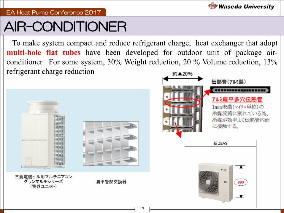
AIR-CONDITIONERTo make system compact and reduce refrigerant charge, heat exchanger that adopt
multi-hole flat tubes have been developed for outdoor unit of package air-conditioner. For some system, 30% Weight reduction, 20 % Volume reduction, 13%refrigerant charge reduction

IEA Heat Pump Conference 2017Waseda University
8
AIR-CONDITIONER4-stage compressor has been developed to further improve cycle performance
when using CO2 as refrigerant. About 20% COP improvement can be realized.

IEA Heat Pump Conference 2017Waseda University
9
AIR-CONDITIONEROccupant detector has been developed.Left system can supply air at two
different temperatures for two separateoccupants.
Right system can find out best way tosupply air from image sensor analysis.Using this, 24% energy saving can berealized.
"Air-Flow-Paths" OFF ON
Foot Temperature 24.1℃ 24.2℃
Setting Temperature 26.5℃ 23.0℃
Electric Energyper one hour 790Wh 597Wh
Effect of Power Saving 24.4%
-3.5℃
"Air-Flow-Paths" OFF "Air-Flow-Paths" ON
Air ConditioningArea
Air ConditioningArea

IEA Heat Pump Conference 2017Waseda University
10
GAS ENGINE HEAT PUMP
ExpansionValve
Condenser
Evaporator
Compressor
Gas Engine
Waste heat
City gas
0
2
4
6
8
10
12
14
110% 100% 90% 80% 70%
エンジン回転数:定格
エンジン回転数:最大
Sub-
cool
of re
frig
eran
t [℃
]
Refrigerant charge
Gas engine driven heat pump (GHP) is widely used in Japan. Latest system can supply electricity when electric supply stops. New refrigerant leak detect method is developed. This system can be driven only by stable waste heat of gas engine without any load. From this stable driving, refrigerant leak can be easily detected.

IEA Heat Pump Conference 2017Waseda University
11
HEAT PUMP STEAM GENERATOR
0 200 400 600 800 1000102
103
104
SpecificenthalpykJ/kg
PressurekPa
180
T=4
0o C
BUTANE
60 80 100
120
140
160
200
膨張弁開度 100 パルス 110 パルス 120 パルス 130 パルス 140 パルス 150 パルス
A very compact 120 oC steam generator heat pump system with a heat capacity ofapproximately 30 kW was developed. We are developing a 165 oC steamgenerating heat pump system For this system, we optimized cycle and componentsusing a theoretical analysis and experiment.
IEA Heat Pump Conference 2017Waseda University
12
CENTRIFUGAL CHILLER
12
冷却 除湿
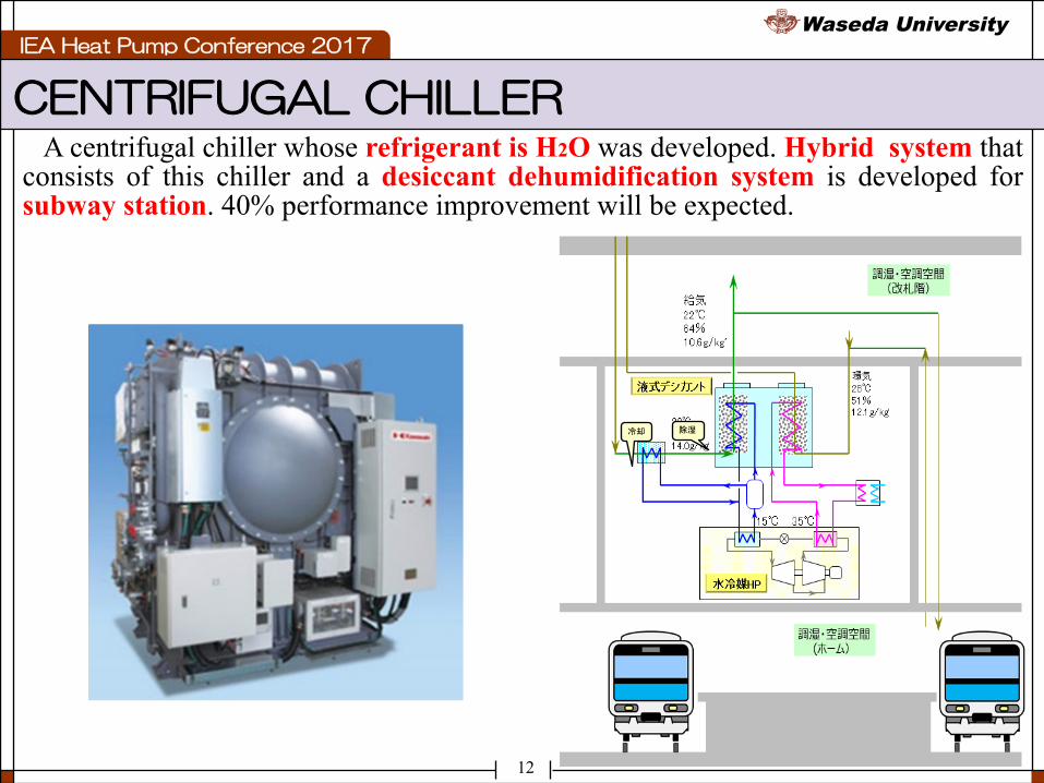
A centrifugal chiller whose refrigerant is H2O was developed. Hybrid system thatconsists of this chiller and a desiccant dehumidification system is developed forsubway station. 40% performance improvement will be expected.

IEA Heat Pump Conference 2017Waseda University
13
ABSORPTION TECHNOLOGIES
SE/DL cycle has been developed. This cycle can be driven by wider glide of heat sources. This system can use lower grade heat sources.

IEA Heat Pump Conference 2017Waseda University
14
ABSORPTION TECHNOLOGIES
0 20 40 60 80 100 120 140 160 180 2000
20
40
60
80
100
120
1400% 40% 50% 60%
70%
Solution temperature TS oC
Refri
gera
nt te
mpe
ratu
re T
R o C
Factories normally use an 8 kgf/cm2 steam pipingnetwork to supply steam at a temperature ofapproximately 180 oC.
To realize 180 oC steam generation, we developeddouble-lift and triple-stage absorption heattransformers. 180 oC steam generation from 88 oCwas realized with practical system.

IEA Heat Pump Conference 2017Waseda University
15
SIMULATION TECHNOLOGIES
Evaporator
Compressor
Accumulator
Condenser
ExpansionValve
ReversingValve
Indoor Fan
Outdoor Fan
Expansion valve
Compressor
Accumulator
Condenser
Evaporator
Expansionvalve
Heat exchanger Expansionvalve
04080120
Rot
atio
nal
spee
dn C
OM
01 rp
s
0200400600
Val
ve1
open
ing
puls
e0
200400600
Val
ve2
open
ing
puls
e
0200400600
Val
ve3
open
ing
puls
e
0200400600
Val
ve4
open
ing
puls
e
0
5
10
Coo
ling
capa
city
QEV
A1 k
W
0
5
10
Coo
ling
capa
city
QEV
A2 k
W
0
5
10
Coo
ling
capa
city
QEV
A3 k
W
0
5
10
Coo
ling
capa
city
QEV
A4 k
W
02468
Com
pres
sor
inpu
tkW
0102030
Coo
ling
capa
city
kW
-200 0 200 400 600 800 10000
5
10
CO
PTime t s
2000
2500
3000
Pres
sure
P CO
M O
kPa
-200 0 200 400 600 800 1000500
1000
1500
Time t s
Pres
sure
P CO
M I k
Pa
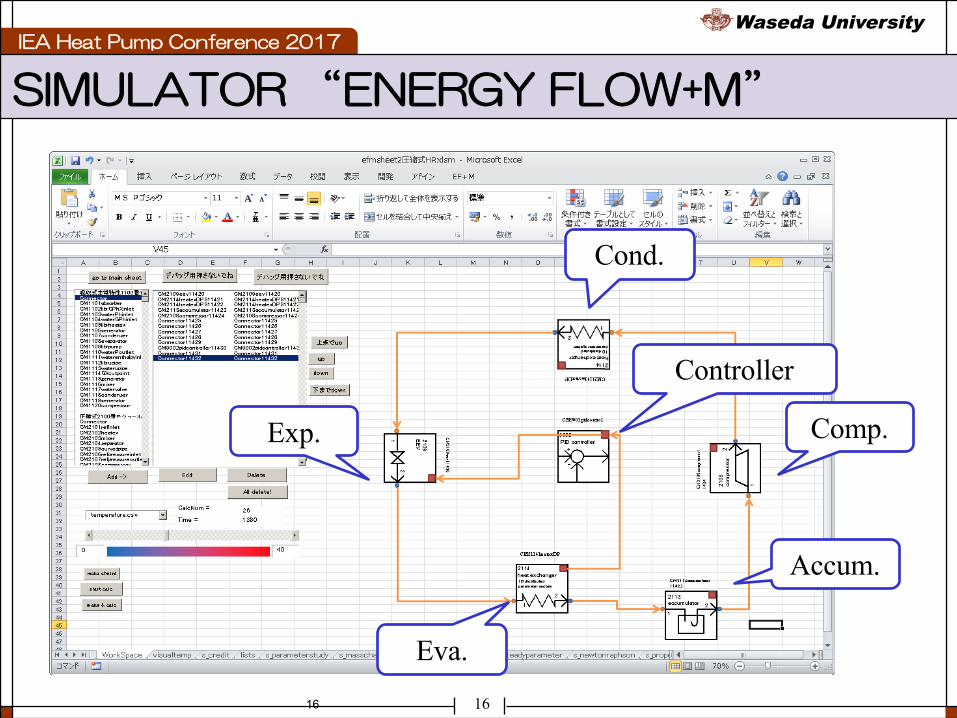
“Energy flow +M” is a general purpose energy system analysis simulator wedeveloped. Steady and unsteady calc. of almost every type of heat pump –compression, absorption, adsorption can be realized.
Japan refrigeration and air conditioning industrial association (JRAIA) adoptour simulator as common calculation tool to predict the cycle performance of heatpump with various refrigerants.
IEA Heat Pump Conference 2017Waseda University
1616
SIMULATOR “ENERGY FLOW+M”
Exp.
Cond.
Accum.
Comp.
Eva.
Controller

IEA Heat Pump Conference 2017Waseda University
17
DYNAMICS OF VRF
17
Expansion valve
Compressor
Accumulator
Condenser
Evaporator
Expansionvalve
Heat exchanger Expansionvalve
04080120
Rot
atio
nal
spee
dn C
OM
01 rp
s
0200400600
Val
ve1
open
ing
puls
e0
200400600
Val
ve2
open
ing
puls
e
0200400600
Val
ve3
open
ing
puls
e
0200400600
Val
ve4
open
ing
puls
e
0
5
10
Coo
ling
capa
city
QEV
A1 k
W
0
5
10
Coo
ling
capa
city
QEV
A2 k
W
0
5
10
Coo
ling
capa
city
QEV
A3 k
W
0
5
10
Coo
ling
capa
city
QEV
A4 k
W
02468
Com
pres
sor
inpu
tkW
0102030
Coo
ling
capa
city
kW
-200 0 200 400 600 800 10000
5
10
CO
P
Time t s
2000
2500
3000
Pres
sure
P CO
M O
kPa
-200 0 200 400 600 800 1000500
1000
1500
Time t s
Pres
sure
P CO
M I
kPa
Fig. Dynamics of VRF
Dynamic interaction of VRF system can be calculated

IEA Heat Pump Conference 2017Waseda University
18
GHP CALCULATION
18
0.4 0.6 0.8 1 1.20.20.40.60.81
1.21.4
Coolingcapacity-
Outdoorfanrotationalspeed-0.4 0.6 0.8 1 1.20.2
0.40.60.81
1.21.4
Pressure
P COMOkPa
0.4 0.6 0.8 1 1.20.20.40.60.81
1.21.4
Electricinpu
t-
Outdoorfanrotationalspeed%
0.4 0.6 0.8 1 1.20.20.40.60.81
1.21.4
Pressure
P COMIkPa
0.4 0.6 0.8 1 1.20.20.40.60.81
1.21.4
Gasinp
ut-
Outdoorfanrotationalspeed-
0.4 0.6 0.8 1 1.20.20.40.60.81
1.21.4
COP
0.4 0.6 0.8 1 1.20.20.40.60.81
1.21.4
COPg
Outdoorfanrotationalspeed%
0.4 0.6 0.8 1 1.20.20.40.60.81
1.21.4
COPp
Outdoorfanrotationalspeed%
0.4 0.6 0.8 1 1.20.20.40.60.81
1.21.4
Coolingcapacity-
Outdoorfanrotationalspeed-0.4 0.6 0.8 1 1.20.2
0.40.60.81
1.21.4
Pressure
P COMOkPa
0.4 0.6 0.8 1 1.20.20.40.60.81
1.21.4
Electricinpu
t-Outdoorfanrotationalspeed%
0.4 0.6 0.8 1 1.20.20.40.60.81
1.21.4
Pressure
P COMIkPa
0.4 0.6 0.8 1 1.20.20.40.60.81
1.21.4
Gasinpu
t-
Outdoorfanrotationalspeed-
0.4 0.6 0.8 1 1.20.20.40.60.81
1.21.4
COP
0.4 0.6 0.8 1 1.20.20.40.60.81
1.21.4
COPg
Outdoorfanrotationalspeed%
0.4 0.6 0.8 1 1.20.20.40.60.81
1.21.4
COPp
Outdoorfanrotationalspeed%
0.4 0.6 0.8 1 1.20.20.40.60.81
1.21.4
Coolingcapacity-
Outdoorfanrotationalspeed- 0.4 0.6 0.8 1 1.22000
2500
3000
3500
4000
Pressure
P COMOkPa
0.4 0.6 0.8 1 1.20.20.40.60.81
1.21.4
Electricinpu
t-
Outdoorfanrotationalspeed%
0.4 0.6 0.8 1 1.20
500
1000
1500
2000
Pressure
P COMIkPa
Outdoorfanrotationalspeed-0.4 0.6 0.8 1 1.20.20.40.60.81
1.21.4
Gasinpu
t-
Outdoorfanrotationalspeed-
0.4 0.6 0.8 1 1.20.20.40.60.81
1.21.4
COP
0.4 0.6 0.8 1 1.20.20.40.60.81
1.21.4
COPg
Outdoorfanrotationalspeed%
0.4 0.6 0.8 1 1.20.20.40.60.81
1.21.4
COPp
Outdoorfanrotationalspeed%
Fig. Performance calc. of Gas engine heat pump

IEA Heat Pump Conference 2017Waseda University
19
MULTI PHYISICS SIMULATION
19
0
10
20
30
40
50
60
22
23
24
25
26
27
28
-10 0 10 20 30 40 50 60 70 80 90 100 110 120
圧縮機回転数rps
室内温度℃
時 間 m in
室内温度
制御出力(圧縮機回転数)
室内温度設定値
室内温度平均
400
800
1600
3200
6400
150 200 250 300 350 400 450 500
圧力
kP
a
比エンタルピ kJ/k g
R410A
室内温度設定 26℃, 冷媒流量 0.109 k g/s
室内温度設定 24℃, 冷媒流量 0.073 k g/s
側面図(B-B’面)_温度分布
A A’
・27.4℃
・22.4℃
・24.6℃
Sensor : 26.1℃
・23.0℃・23.5℃
℃
26℃設定定常時上面図(A-A’面)_温度分布B B’
・26.7℃
・26.1℃
・24.4℃
・25.2℃
・24.5℃
・23.7℃
・24.2℃
・23.6℃
・22.4℃・22.7℃
側面図(B-B’面)_気流分布m/ s
・0.04m/s ・0.08m/s
・0.27m/s
・0.27m/s
・0.16m/s
・0.18m/s
・0.06m/s
・0.17m/s
・0.29m/s・0.11m/s
部屋室内機
室外機
Heat pump cycle Indoor temp. control Super-heat control
Temperature and humidity distribution
30
40
50
60
70
80
90
100
0
2
4
6
8
10
12
14
-10 0 10 20 30 40 50 60 70 80 90 100 110 120
膨張弁開度pulse
過熱度℃
時 間 m in
過熱度 制御出力(膨張弁開度)
過熱度設定値

IEA Heat Pump Conference 2017Waseda University
20
SIMULATION TECHNOLOGIES
0 1 2 30
0.3
0.6
0.9
1.2
1.5
Elec
tric
inpu
t E k
W
R 410A(Rated cooling) HC 600a(Rated cooling) R 410A HC 600a
0
20
40
60
80
100
PressureP* %
Distance-
COM
inlet
COM
out
let
CON
inlet
CON
out
let
EXP
inlet
EXP
outle
t
EVA
inlet
EVA
out
let
COM
inlet
R-410A(n=100%) R-410A(50%) HC-600a(100%) HC-600a(50%)
0 1 2 30
2
4
6
8
COP
-
0 1 2 30
50
100
150
200
Pres
sure
dro
p ΔP E
VA
kPa
Cooling capacity Q kW
R410A R600a
Theoretical analysis R410A R600a
Evaporation temperature,℃ 10.0
Condensation temperature,℃ 45.0
Sub cooled temperature,℃ 5.0
Super heat temperature,℃ 5.0
Adiabatic efficiency,- 1.0
Theoretical COP,- 6.40 7.13
Compressor inlet specific volume, m3/kg
0.0248 0.174
Evaporator specific enthalpy difference, kJ/kg
164 280
Refrigerant flow rate per unit of cooling capacity, kg/(s・kW)
0.00610 0.00357
R600a drop-in calc. and experiment are carried out. Result show that under ratedconditions, electricity consumption was greatly decreased, but cooling capacity wasalso decreased. Enery saving can’t be realized only by drop-in.
IEA Heat Pump Conference 2017Waseda University
21
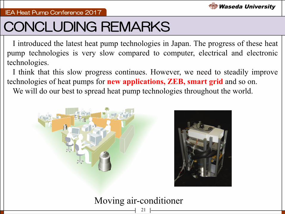
CONCLUDING REMARKSI introduced the latest heat pump technologies in Japan. The progress of these heat
pump technologies is very slow compared to computer, electrical and electronictechnologies.
I think that this slow progress continues. However, we need to steadily improvetechnologies of heat pumps for new applications, ZEB, smart grid and so on.
We will do our best to spread heat pump technologies throughout the world.
Moving air-conditioner